Embed Size (px)
Citation preview
ES5455.1 Load Carrier Board (4 -CH)
ES5450.3 Load Carrier Board for 4 RB CRI2x InjectorsES5451.4 Load Carrier Board for 4 RB HDEV5 InjectorsES5452.1 Load Carrier Board for 4 RB HDEV5 Injectors, CVOES5453.1 Load Carrier Board for 4 RB HDEV6 Injectors, CVOES5457.1 Load Carrier Board for 4 RB CRI2x Injectors, VCCES5458.1 Load Carrier Board for 4 RB PFI EV14 Injectors, CVO
User’s Guide

2
Copyright
The data in this document may not be altered or amended without special noti-fication from ETAS GmbH. ETAS GmbH undertakes no further obligation in rela-tion to this document. The software described in it can only be used if thecustomer is in possession of a general license agreement or single license. Usingand copying is only allowed in concurrence with the specifications stipulated inthe contract.
Under no circumstances may any part of this document be copied, reproduced,transmitted, stored in a retrieval system or translated into another languagewithout the express written permission of ETAS GmbH.
© Copyright 2019 ETAS GmbH, Stuttgart
The names and designations used in this document are trademarks or brandsbelonging to the respective owners.
V1.0.0 R02 EN - 09.2019

Contents
ETAS Contents
1 Introduction . . . . . . . . . . . . . . . . . . . . . . . . . . . . . . . . . . . . . . . . . . . . . . . . . . . . . . 51.1 Properties . . . . . . . . . . . . . . . . . . . . . . . . . . . . . . . . . . . . . . . . . . . . . . . . . . . 5
1.1.1 Properties of the ES5455.1 Load Carrier Board and it’s Variants ES5450.3, ES5451.4, ES5452.1, ES5453.1, ES5457.1 and ES5458.1 6
1.1.2 ES5455.1 Block Diagram. . . . . . . . . . . . . . . . . . . . . . . . . . . . . . . . . 81.2 Basic Safety Notices . . . . . . . . . . . . . . . . . . . . . . . . . . . . . . . . . . . . . . . . . . . 9
1.2.1 Identification of Safety Notices . . . . . . . . . . . . . . . . . . . . . . . . . . . . 91.2.2 General Safety Information . . . . . . . . . . . . . . . . . . . . . . . . . . . . . . . 91.2.3 Requirements for Users and Duties for Operators. . . . . . . . . . . . . . . 91.2.4 Intended Use . . . . . . . . . . . . . . . . . . . . . . . . . . . . . . . . . . . . . . . . . 10
1.3 Identifications on the Product . . . . . . . . . . . . . . . . . . . . . . . . . . . . . . . . . . . 151.3.1 CE Mark . . . . . . . . . . . . . . . . . . . . . . . . . . . . . . . . . . . . . . . . . . . . 161.3.2 KC Mark . . . . . . . . . . . . . . . . . . . . . . . . . . . . . . . . . . . . . . . . . . . . 161.3.3 RoHS Conformity. . . . . . . . . . . . . . . . . . . . . . . . . . . . . . . . . . . . . . 161.3.4 P007 Identification in Accordance with ISO 7010:2011 . . . . . . . . . 16
1.4 Product Return and Recycling . . . . . . . . . . . . . . . . . . . . . . . . . . . . . . . . . . 171.5 Materials Subject to Declaration . . . . . . . . . . . . . . . . . . . . . . . . . . . . . . . . . 171.6 About this Manual . . . . . . . . . . . . . . . . . . . . . . . . . . . . . . . . . . . . . . . . . . . 18
1.6.1 Working with this Manual . . . . . . . . . . . . . . . . . . . . . . . . . . . . . . . 18
2 Properties and Functions . . . . . . . . . . . . . . . . . . . . . . . . . . . . . . . . . . . . . . . . . . . . 212.1 Design of an Injector Simulation Environment . . . . . . . . . . . . . . . . . . . . . . . 212.2 Figures of all Variants . . . . . . . . . . . . . . . . . . . . . . . . . . . . . . . . . . . . . . . . . 23
2.2.1 ES5455.1 Load Carrier Board. . . . . . . . . . . . . . . . . . . . . . . . . . . . . 232.2.2 ES5450.3 Load Carrier Board for 4 RB CRI2x Injectors . . . . . . . . . . 252.2.3 ES5451.4 Load Carrier Board for 4 RB HDEV5 Injectors . . . . . . . . . 252.2.4 ES5452.1 Load Carrier Board for 4 RB HDEV5 Injectors, CVO. . . . . 252.2.5 ES5453.1 Load Carrier Board for 4 RB HDEV6 Injectors, CVO. . . . . 262.2.6 ES5457.1 Load Carrier Board for 4 RB CRI2x Injectors, VCC. . . . . . 26
ES5455.1 Load Carrier Board (4 -CH) - User’s Guide 3

4
Contents ETAS
2.2.7 ES5458.1 Load Carrier Board for 4 RB PFI EV14 Injectors, CVO . . . 262.3 Installation / Removal of the Plug-In Boards into / from the ES5300.1-A Housing
and ES5300.1-B Housing . . . . . . . . . . . . . . . . . . . . . . . . . . . . . . . . . . . . . . 272.4 Assembly of the Piggybacks on the ES5455.1 Load Carrier Board . . . . . . . . 302.5 Exchange of the Frontplate of the ES5455.1 Load Carrier Board . . . . . . . . . 302.6 Fuses . . . . . . . . . . . . . . . . . . . . . . . . . . . . . . . . . . . . . . . . . . . . . . . . . . . . . 312.7 Interface for Load Modules on the ES5455.1 Load Carrier Board . . . . . . . . . 322.8 Piezo Signal Generator . . . . . . . . . . . . . . . . . . . . . . . . . . . . . . . . . . . . . . . . 322.9 Equivalent Circuit . . . . . . . . . . . . . . . . . . . . . . . . . . . . . . . . . . . . . . . . . . . . 33
3 Connections and Plug Connections. . . . . . . . . . . . . . . . . . . . . . . . . . . . . . . . . . . . 353.1 Backplane Connector CO402 . . . . . . . . . . . . . . . . . . . . . . . . . . . . . . . . . . . 353.2 Plug Connector X1 . . . . . . . . . . . . . . . . . . . . . . . . . . . . . . . . . . . . . . . . . . . 38
3.2.1 Technical Details of Plug Connector X1 . . . . . . . . . . . . . . . . . . . . . 393.2.2 Connecting the NCC Analog Outputs to an ECU . . . . . . . . . . . . . . 41
3.3 Plug Connector CO1200 on ES5455.1, CO150 and CO100 on the Load Mod-ules . . . . . . . . . . . . . . . . . . . . . . . . . . . . . . . . . . . . . . . . . . . . . . . . . . . . . . 42
4 Technical Data and Standards . . . . . . . . . . . . . . . . . . . . . . . . . . . . . . . . . . . . . . . . 434.1 Technical Data . . . . . . . . . . . . . . . . . . . . . . . . . . . . . . . . . . . . . . . . . . . . . . 434.2 Standards Met . . . . . . . . . . . . . . . . . . . . . . . . . . . . . . . . . . . . . . . . . . . . . . 44
5 Ordering Data. . . . . . . . . . . . . . . . . . . . . . . . . . . . . . . . . . . . . . . . . . . . . . . . . . . . 45
6 ETAS Contact Addresses . . . . . . . . . . . . . . . . . . . . . . . . . . . . . . . . . . . . . . . . . . . . 47
Index . . . . . . . . . . . . . . . . . . . . . . . . . . . . . . . . . . . . . . . . . . . . . . . . . . . . . . . . . . 49
ES5455.1 Load Carrier Board (4 -CH) - User’s Guide

ETAS Introduction
1 Introduction
This User's Guide contains the description of the ES5455.1 Load Carrier Boardand its variants ES5450.3, ES5451.4, ES5452.1, ES5450.3, ES5457.1 andES5458.1 mounted with load modules.
This chapter contains information about the following topics:
• "Properties" on page 5
• "ES5455.1 Block Diagram." on page 8
• "Basic Safety Notices" on page 9
• "Identifications on the Product" on page 15
• "CE Mark" on page 16
• "KC Mark" on page 16
• "RoHS Conformity" on page 16
• "Product Return and Recycling" on page 17
• "Materials Subject to Declaration" on page 17
• "About this Manual" on page 18
1.1 Properties
The ES5455.1 Load Carrier Board is a carrier board for load simulations, e.g.injector loads, in a LABCAR HiL system.
Simulated Injector Loads
To simulate injector loads, the following variants mounted with load modulesbased on the ES5455.1 Load Carrier Board are available:
• ES5450.3 Load Carrier Board for 4 RB CRI2x Injectors
• ES5451.4 Load Carrier Board for 4 RB HDEV5 Injectors
• ES5452.1 Load Carrier Board for 4 RB HDEV5 Injectors, CVO
• ES5453.1 Load Carrier Board for 4 RB HDEV6 Injectors, CVO
• ES5457.1 Load Carrier Board for 4 RB CRI2x Injectors, VCC
• ES5458.1 Load Carrier Board for 4 RB PFI EV14 Injectors, CVO
ES5450.3 and ES5451.4 are the successors to ES4450.2 and ES4451.3. ES5450.3and ES5451.4 have the same functions as their respective predecessor models.
Supported Control Algorithms
The ES5452.1, ES5453.1, ES5457.1 and the ES5458.1 have an expanded scopeof functions. They enable an additional more precise simulation and modulationof the injection time through integrated functions for the control algorithms ofthe ECU.
These control algorithms are the following:
• CVO (Controlled Valve Operation) in the case of ES5452.1, ES5453.1 and ES5458.1
• VCC (Valve Close Control) for diesel common rail injection in the case of ES5457.1.
ES5455.1 Load Carrier Board (4 -CH) - User’s Guide 5

6
Introduction ETAS
• NCC (Needle Closing Control) for diesel common rail injection in the case of ES5457.1This control algorithm allows the detection of the following:
Needle opening time
Needle reversal time
Needle closing time
The expanded functions can be deactivated by the user in LABCAR OPERATOR.After deactivating the function for CVO, the ES5452.1 can be operated analo-gous to ES5451.4, ES4451.4 and ES4451.3. Also, the ES5457.1 can be used inthe same way as ES4450.3 and ES4450.2 after deactivating the functions forVCC and NCC.
Number of Simulated Injection Loads
In the ES5300.1-A Housing and the ES5300.1-B Housing, it is possible to install5 cards of width 14 HP. Fully mounted, it enables the simulation of 20 injectionloads per housing.
1.1.1 Properties of the ES5455.1 Load Carrier Board and it’s Variants ES5450.3, ES5451.4, ES5452.1, ES5453.1, ES5457.1 and ES5458.1
• 4 U/14 HP add-on card for a LABCAR HiL system.
• Compatibility with the ES5300.1-A Housing and the ES5300.1-B Housing.
• Slot for 4 loads.
• Four load inputs for connecting four simulated injection loads to an ECU.
• Current measurement for four loads via four galvanically isolated channels.
• Voltage measurement for four loads via four galvanically isolated channels
• Analog output Online_Probe for current or voltage measurement at one selectable load
• On-board analysis of load current and load voltage
• Four digital outputs I_Dig_Out_0...I_Dig_Out_3 for outputting the injec-tion time for each load. Based on the load response, the opening and closing time of the respective load is also being output
• Four analog outputs for NCC
The variants have the following additional properties:
ES5455.1 Load Carrier Board
• Slot for four loads
ES5450.3 Load Carrier Board for 4 RB CRI2x Injectors
• Simulation for four injectors of the Bosch Common Rail System
ES5451.4 Load Carrier Board for 4 RB HDEV5 Injectors
• Simulation for injectors of the Bosch HDEV5 gasoline direct injection
ES5455.1 Load Carrier Board (4 -CH) - User’s Guide
ETAS Introduction
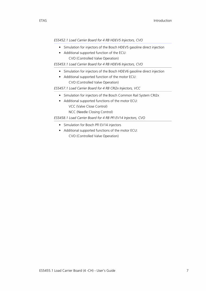
ES5452.1 Load Carrier Board for 4 RB HDEV5 Injectors, CVO
• Simulation for injectors of the Bosch HDEV5 gasoline direct injection
• Additional supported function of the ECU:
CVO (Controlled Valve Operation)
ES5453.1 Load Carrier Board for 4 RB HDEV6 Injectors, CVO
• Simulation for injectors of the Bosch HDEV6 gasoline direct injection
• Additional supported function of the motor ECU:
CVO (Controlled Valve Operation)
ES5457.1 Load Carrier Board for 4 RB CRI2x Injectors, VCC
• Simulation for injectors of the Bosch Common Rail System CRI2x
• Additional supported functions of the motor ECU:
VCC (Valve Close Control)
NCC (Needle Closing Control)
ES5458.1 Load Carrier Board for 4 RB PFI EV14 Injectors, CVO
• Simulation for Bosch PFI EV14 injectors
• Additional supported functions of the motor ECU:
CVO (Controlled Valve Operation)
ES5455.1 Load Carrier Board (4 -CH) - User’s Guide 7

ES5455.1 Load Carrier Board (4 -C
H)-
User’s G
uide8
ETAS
Introduction
1
ES5455.1
Control Interface
Control Interface
Ribbon cable
ontrol, Feedback
2
I
U
Load 3
Piggyback Load
.1.2 ES5455.1 Block Diagram.
Fig. 1-1 Block diagram for ES5455.1 Load Carrier Board
C
I
U
Load 0
I
U
Load 1
I
U
Load
Speaker
DAC
ADC ADC ADC ADC ADC ADC ADC ADC
Multiplexer 8:1
Control FPGAI_Dig_Out_0...3
Online Probe
NCC_0...3DAC

ETAS Introduction
1.2 Basic Safety Notices
Observe the following safety notices to avoid health issues or damage to thedevice.
1.2.1 Identification of Safety Notices
The safety notices contained in this manual are identified with the danger symbolshown below:
The safety notices shown below are used for this purpose. They provide notes toextremely important information. Read this information carefully.
1.2.2 General Safety Information
Observe the following safety notices to avoid health issues or damage to thedevice.
ETAS GmbH does not assume any liability for damages resulting from improperhandling, unintended use or non-observance of the safety precautions.
1.2.3 Requirements for Users and Duties for Operators
The product may be assembled, operated and maintained only if you have thenecessary qualification and experience for this product. Improper use or use by auser without sufficient qualification can lead to damages or injuries to one'shealth or damages to property.The system integrator is responsible for the safety of systems that use the prod-uct.
CAUTION!
identifies a hazard with low risk that could result in minor or medium physical injuries or property damages, if not avoided.
WARNING!
indicates a possible danger with moderate risk of death or (serious) injury, if not avoided.
DANGER!
indicates an immediate danger with a high risk of death or serious injury, if not avoided.
Note
The User's Guide and the Product Safety Advice must be read carefully prior to the startup of the product!
ES5455.1 Load Carrier Board (4 -CH) - User’s Guide 9

10
Introduction ETAS
General Safety at Work
Follow the existing regulations for work safety and accident prevention. All appli-cable regulations and laws regarding operation must be strictly adhered to whenusing this product.
1.2.4 Intended Use
The ES5455.1 Load Carrier Board and its populated variants ES5450.3,ES5451.4, ES5452.1, ES5453.1, ES5457.1 and ES5458.1 are plug-in cards forthe ES5300.1-A Housing and the ES5300.1-B Housing.
The ES5455.1 Load Carrier Board consists of the following:
• Slot for a load emulation for simulating injection valves with connections to ECU output stages
• Digital and analog output interfaces to an ES5300.1-A-based hardware-in-the-loop system or for connecting oscilloscopes or other measurement devices
• SPI Interface to the ES5300.1-A Housing or the ES5300.1-B Housing
The ES5450.3, ES5451.4, ES5452.1, ES5453.1, ES5457.1 and ES5458.1 plug-incards consist of the following:
• Load emulation for simulating injection valves with connections to ECU output stages
• Digital and analog output interfaces for the ES5300.1-A-based hardware-in-the-loop system or for connecting oscilloscopes or other measurement devices
• SPI Interface to the ES5300.1-A Housing and to the ES5300.1-B Housing
The ES5455.1 and its variants ES5450.3, ES5451.4, ES5453.1, ES5452.1,ES5457.1 and ES5458.1 mounted with load modules may be operated only inthe ES5300.1-A Housing and in the ES5300.1-B Housing.
The intended use of the ES5455.1 Load Carrier Board and its populated variantsES5450.3, ES5451.4, ES5452.1, ES5453.1, ES5457.1 and ES5458.1 in anES5300.1-A Housing or ES5300.1-B Housing is:
• Use as a component in industrial lab facilities or at industrial workplaces
• Use as hardware interface for ECUs in a hardware-in-the-loop test system
• Use in conjunction with ETAS software that supports the ES5300.1-A Housing and the ES5300.1-B Housing
• Use as interface in cooperation with software programs that operate the standardized, documented and open APIs of ETAS software products
The ES5455.1 Load Carrier Board and its populated variants ES5450.3,ES5451.4, ES5452.1, ES5453.1, ES5457.1 and ES5458.1 are not intended forthe following:
• Use within a vehicle on the road
• Use as part of a life support system
• Use as part of a medical application
• In applications where misuse can lead to injuries or damages
ES5455.1 Load Carrier Board (4 -CH) - User’s Guide

ETAS Introduction
• Use in environments in which conditions prevail that fall outside the spec-ified ranges (see "Ambient Conditions" on page 44)
• Use with signal conditioning that falls outside the specified ranges (see voltages, currents and power consumption in the chapter "Technical Data" on page 43)
Requirements for the Technical State of the Product
The product is designed in accordance with state-of-the-art technology and rec-ognized safety rules. The product may be operated only in a technically flawlesscondition and according to the intended purpose and with regard to safety anddangers as stated in the respective product documentation. If the product is notused according to its intended purpose, the protection of the product may beimpaired.
Requirements for Operation
The following requirements are necessary for safe operation:
• Use the product only according to the specifications in the corresponding User's Guide. With any deviating operation, the product safety is no lon-ger ensured.
• Do not use the product in a wet or damp environment.
• Do not use the product in potentially explosive atmospheres.
Electrical Safety and Power Supply
Observe the regulations applicable at the operating location concerning electricalsafety as well as the laws and regulations concerning work safety!
WARNING!
Danger from high voltages!The components, plug connectors and conductor paths of the ES5455.1 Load Carrier Board and its populated variants ES5450.3, ES5451.4, ES5452.1, ES5453.1, ES5457.1 and ES5458.1 may have dangerous voltages. These voltages can still be present even after the ES5455.1 Load Carrier Board and its populated variants ES5450.3, ES5451.4, ES5452.1, ES5453.1, ES5457.1 and ES5458.1 have been removed from the ES5300.1-A Housing or if the ES5300.1-A Housing or the ES5300.1-B Housing has been switched off. Make sure that the products are protected from external contact during operation. Switch off the ES5300.1-A Housing and the ES5300.1-B Housing and unplug from the mains. Wait at least three minutes before removing the products.Failure to do so poses a danger to life and health.
ES5455.1 Load Carrier Board (4 -CH) - User’s Guide 11

12
Introduction ETAS
Power Supply
The products are powered by the ES5300.1-A Housing or the ES5300.1-B Hous-ing via the PCIe Backplane Connector.
Insulation Requirements for Lab Power Supplies to Circuits Connected to the HIL System:
• The power supply to live circuitry must be safely isolated from the supply voltage. For example, use a car battery or a suitable lab power supply.
• Only use lab power supplies with dual protection for the supply network (with double/reinforced insulation (DI/RI)). This requirement is met by lab power supplies that comply with IEC/EN 60950 or IEC/EN 61010.
• The lab power supply must be approved for use at a height of 2000 m and in ambient temperatures of up to 40 °C.
De-energizing a Plug-in Board
Switch off the ES5300.1-A Housing or the ES5300.1-B Housing and externalpower supplies, and unplug the power plug and other connectors attached tothe plug-in board. Wait at least three minutes before removing the plug-inboard.
WARNING!
Danger - electromagnetic radiation!During operation, the ES5455.1 Load Carrier Board and its populated variants ES5450.3, ES5451.4, ES5452.1, ES5453.1, ES5457.1 and ES5458.1 and loads connected to them, can emit electromagnetic radiation, which can cause cardiac pacemakers or implanted defibril-lators to malfunction or become damaged. The products may only be operated in areas where persons with pacemakers are prohibited from entering. The entrances to these areas must bear sign P007 "No access for persons with cardiac pace-makers or implanted defibrillators" in a clearly visible position in accordance with ISO 7010:2011 "Registered Safety Signs".Failure to observe this rule can lead to health hazards and even death for persons with pacemakers and implanted defibrillators.
WARNING!
Fire hazard!Use only fuses that meet the specification in Tab. 2-1 on page 31! Never bridge defective fuses!Failure to observe the fuse specification can lead to excess currents, short circuits and fires.
ES5455.1 Load Carrier Board (4 -CH) - User’s Guide
ETAS Introduction
Approved Cables
The signal lines must not exceed a maximum length of 3 m.
Requirements for the Installation Location
Requirements for Ventilation
Transport and Installation
To avoid damages to the hardware from electrostatic discharge, please observethe following precautionary measures:
WARNING!
Fire hazard!Use only approved cables for creating cable assemblies (e.g. for con-necting the ECU and external loads). The cables used must, in partic-ular, be suitable for the currents, voltages and temperatures which occur and must be flameretardant in accordance with one of the fol-lowing standards IEC 60332-1-2, IEC 60332-2-2, UL 2556/UL1581VW-1!
WARNING!
This is class A equipment. This equipment can cause radio interfer-ence in residential areas. Should that be the case, the operator may be requested to institute reasonable measures.
CAUTION!
The air circulation inside the ES5300.1-A housing and the ES5300.1-B housing can be ensured only if all free slots are covered with front plates. Otherwise, it may lead to overtemperatures and trip the over-temperature protection of the ES5300.1-A or the ES5300.1-B. For this reason, install front plates in all free slots!
CAUTION!
Some components of the ES5455.1 Load Carrier Board and its popu-lated variants ES5450.3, ES5451.4, ES5452.1, ES5453.1, ES5457.1 and ES5458.1 to be installed can be damaged or destroyed by elec-trostatic discharges. Leave the plug-in cards in their transport packag-ing until their installation. Remove, configure and install the the ES5455.1 Load Carrier Board and its populated variants ES5450.3, ES5451.4, ES5452.1, ES5453.1, ES5457.1 and ES5458.1 only at a workplace secured against static discharges.
CAUTION!
In order to prevent damage to the plug-in boards and the LABCAR housing, and thereby also avoid damage to property or health, observe the installation instructions and information contained in the relevant User's Guides.
ES5455.1 Load Carrier Board (4 -CH) - User’s Guide 13

14
Introduction ETAS
Connecting/Disconnecting Devices
To avoid injuries and hardware damages, observe the following precautionarymeasures:
• Do not apply any voltages to the connections of the products that do not correspond to the specifications of the respective connection.
• Do not connect or disconnect any devices while the ES5300.1-A Housing or ES5300.1-B Housing or external devices are switched on. First, switch off the ES5300.1-A Housing or ES5300.1-B Housing by shutting down the real-time PC and by activating the On/Off switch at the rear and unplug the power cable.
• When plugging in connectors, ensure that they are inserted straight and no pins are bent.
• When crimping the plug contacts of Positronic, use only the crimping tool intended for this purpose.
Maintenance
The products do not require maintenance.
Repairs
If an ETAS hardware product needs to be repaired, return the product to ETAS.
Cleaning
The products are not expected to require cleaning.
CAUTION!
If cards (e.g. for startup or calibration) are unlocked but not com-pletely removed from the housing, they must be pulled out far enough that the distance between the respective card and the back-plane of the housing is at least 1 cm. Otherwise, contacts may be established between the cards and lead to their destruction.
ES5455.1 Load Carrier Board (4 -CH) - User’s Guide

ETAS Introduction
1.3 Identifications on the Product
The following Symbols are Used for Product Labeling:
Observe the information in the chapter "Technical Data and Standards"on page 43.
Symbol Description
The User's Guide must be read prior to the startup of the product
Marking for CE conformity(see "CE Mark" on page 16)
Marking for KCC conformity(see "KC Mark" on page 16)
Marking for China RoHS(see "RoHS Conformity" on page 16)
Marking for conformity with WEEE directive(see "Product Return and Recycling" on page 17)
P007 identification in accordance with ISO 7010:2011: "No access for persons with pacemakers and implanted defibrilla-tors"."Operational malfunction or damage to pacemakers and implanted defibrillators".
ES5455.1 Load Carrier Board (4 -CH) - User’s Guide 15

16
Introduction ETAS
1.3.1 CE Mark
With the CE mark attached to the product or its packaging, ETAS confirms thatthe product corresponds to the product-specific, applicable European Directives.The CE Declaration of Conformity for the product is available upon request.
1.3.2 KC Mark
With the KC mark attached to the product and its packaging, ETAS confirms thatthe product has been registered in accordance with the product-specific KCCguidelines of the Republic of Korea.
1.3.3 RoHS Conformity
European Union
The EU directive 2011/65/EU limits the use of certain dangerous materials forelectric and electronic devices (RoHS conformity).
ETAS confirms that the product meets this directive applicable in the EuropeanUnion.
China
With the China RoHS identification attached to the product or its packaging,ETAS confirms that the product meets the guidelines of the "China RoHS" (Man-agement Methods for Controlling Pollution Caused by Electronic InformationProducts Regulation) applicable in the People's Republic of China.
1.3.4 P007 Identification in Accordance with ISO 7010:2011
Under consideration of the standard ISO 7010:2011, the product is labeled withthe symbol "No access for persons with pacemakers or implanted defibrillators".
The products may be operated only in areas where persons with pacemakers areprohibited from entering. The user is obligated to attach a clearly legible P007identification, "No access for persons with pacemakers or implanted defibrilla-tors" in accordance with ISO 7010:2011 "Registered Safety Signs", at theentrances to these areas.
ES5455.1 Load Carrier Board (4 -CH) - User’s Guide
ETAS Introduction
1.4 Product Return and Recycling
The European Union (EU) released the Directive for Waste Electrical and Elec-tronic Equipment - WEEE to ensure the setup of systems for collecting, treatingand recycling electronic waste in all countries of the EU.
This ensures that the devices are recycled in a resource-friendly way that does notrepresent any risk to personal health and the environment.
Fig. 1-2 WEEE symbol
The WEEE symbol on the product or its packaging identifies that the product maynot be disposed of together with the remaining trash.
The user is obligated to separately collect old devices and provide them to theWEEE return system for recycling.
The WEEE Directive applies to all ETAS devices, but not to external cables or bat-teries.
Additional information about the recycling program of ETAS GmbH is availablefrom the ETAS sales and service locations (see "ETAS Contact Addresses"on page 47).
1.5 Materials Subject to Declaration
Some products from ETAS GmbH (e.g. modules, boards, cables) use componentswith materials that are subject to declaration in accordance with the REACH reg-ulation (EC) no.1907/2006. Detailed information is located in the ETAS download center in the customerinformation "REACH Declaration" < www.etas.com/Reach >. This information iscontinuously being updated.
ES5455.1 Load Carrier Board (4 -CH) - User’s Guide 17

18
Introduction ETAS
1.6 About this Manual
This manual consists of the following chapters:
• "Introduction" on page 5This chapter
• "Properties and Functions" on page 21This chapter features a description of the properties and functions of the components of the ES5455.1 Load Carrier Board and its variants ES5450.3, ES5451.4, ES5452.1, ES5453.1, ES5457.1 and ES5458.1 mounted with load modules.
• "Connections and Plug Connections" on page 35This section provides a description of the connections of the ES5455.1 Load Carrier Board and its variants ES5450.3, ES5451.4, ES5452.1, ES5453.1, ES5457.1 and ES5458.1.
• "Technical Data and Standards" on page 43This chapter contains the technical data of the ES5455.1 Load Carrier Board and its populated variants ES5450.3, ES5451.4, ES5452.1, ES5450.3, ES5457.1 and ES5458.1 and the applicable standards.
• "Ordering Data" on page 45
1.6.1 Working with this Manual
Presentation of Information
All activities to be performed by the user are presented in a "Use Case" format.That is, the goal to be accomplished is briefly defined in the heading, and therespective steps required for reaching this goal are then presented in a list. Thepresentation looks as follows:
Target Definition
Any advance information...
1. Step 1
Any explanation for step 1...
2. Step 2
Any explanation for step 2...
Any concluding comments...
Specific example:
Creating a New File
Before creating a new file, no other file may be open.
1. Select File → New.
The "Create File" dialog box appears.
2. Enter the name of the new file in the “File name” field.
The file name may not have more than 8 characters.
3. Click on OK.
ES5455.1 Load Carrier Board (4 -CH) - User’s Guide

ETAS Introduction
The new file is being created and saved under the name you specified. You cannow work with the file.
Typographical Conventions
The following typographical conventions are used:
Important notes for the user are presented as follows:
Select File → Open. Menu commands are displayed in bold/blue.
Click on OK. Buttons are displayed in bold/blue.
Press <ENTER>. Key commands are printed in small capi-tals enclosed in angle brackets.
The "Open file" dialog window appears.
Names of program windows, dialog win-dows, fields and similar are given in quota-tion marks.
Select the setup.exe file. Text in selection lists, program code, as well as path and file names are displayed using the Courier font.
A conversion between the logical and arithmetic data types is not possible.
Content-based highlights and newly intro-duced terms are placed in italics.
Note
Important note for the user.
ES5455.1 Load Carrier Board (4 -CH) - User’s Guide 19

20
Introduction ETAS
ES5455.1 Load Carrier Board (4 -CH) - User’s Guide

ETAS Properties and Functions
2 Properties and Functions
This chapter features a description of the properties and functions of the compo-nents of the ES5455.1 Load Carrier Board and its variants ES5450.3, ES5451.4,ES5452.1, ES5453.1, ES5457.1 and ES5458.1 mounted with load modules.
• "Design of an Injector Simulation Environment" on page 21
• "Installation / Removal of the Plug-In Boards into / from the ES5300.1-A Housing and ES5300.1-B Housing" on page 27
• "Fuses" on page 31
• "Interface for Load Modules on the ES5455.1 Load Carrier Board" on page 32
• "Piezo Signal Generator" on page 32
• "Equivalent Circuit" on page 33
2.1 Design of an Injector Simulation Environment
This chapter describes how the ES5455.1 Load Carrier Board and its populatedvariants ES5450.3, ES5451.4, ES5452.1, ES5453.1, ES5457.1 and ES5458.1mounted with load modules can be integrated in a LABCAR HiL system.
Fig. 2-1 on page 22 shows a block diagram for integrating the ES545x.y LoadCarrier Boards in a LABCAR HiL system.
ES5455.1 Load Carrier Board (4 -CH) - User’s Guide 21

22
Properties and Functions ETAS
Fig. 2-1 Example for the integration of an ES545x.y in a LABCAR HiL system.
ETAS HiL Simulation Software
HiL-System (ETAS LABCAR)
Real Time Envirionment ETAS ES5300
Injector LoadES545x.y
I Inj.
U Inj.
Angle Synchronous Measurement
Injection time
x
...
Plant Model
Oscilloscope
Onlineprobe
I/O Interface
Injection time,
Start/Stop Injection
(SW variable)
ECUVsupply
INCA
x
x
Loadx+
Loadx-
Example for 1 of x CylindersExample for y HW version (Diesel,
Gasoline,..)
Digital Signal I_Dig_Out_0,...30...15 VAngle sychronous to the other cylinders
External Load
NCC_0...3
ES5455.1 Load Carrier Board (4 -CH) - User’s Guide
ETAS Properties and Functions
2.2 Figures of all Variants
2.2.1 ES5455.1 Load Carrier Board
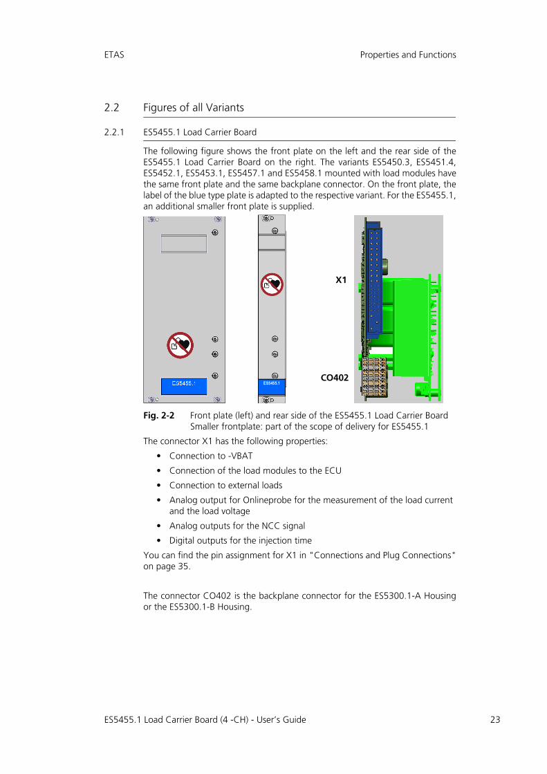
The following figure shows the front plate on the left and the rear side of theES5455.1 Load Carrier Board on the right. The variants ES5450.3, ES5451.4,ES5452.1, ES5453.1, ES5457.1 and ES5458.1 mounted with load modules havethe same front plate and the same backplane connector. On the front plate, thelabel of the blue type plate is adapted to the respective variant. For the ES5455.1,an additional smaller front plate is supplied.
Fig. 2-2 Front plate (left) and rear side of the ES5455.1 Load Carrier BoardSmaller frontplate: part of the scope of delivery for ES5455.1
The connector X1 has the following properties:
• Connection to -VBAT
• Connection of the load modules to the ECU
• Connection to external loads
• Analog output for Onlineprobe for the measurement of the load current and the load voltage
• Analog outputs for the NCC signal
• Digital outputs for the injection time
You can find the pin assignment for X1 in "Connections and Plug Connections"on page 35.
The connector CO402 is the backplane connector for the ES5300.1-A Housingor the ES5300.1-B Housing.
ES5455.1
X1
CO402
ES5455.1 Load Carrier Board (4 -CH) - User’s Guide 23

24
Properties and Functions ETAS
Fig. 2-3 ES5455.1 Load Carrier Board
Note
The load modules of the ES4455.2 Load Carrier Board can also be operated with the ES5455.1 Load Carrier Board. However, the new load modules for CVO / VCC, NCC, which are installed on the ES5452.1, ES5453.1, ES5457.1 and ES5458.1, cannot be operated with the ES4455.2 Load Carrier Board.
ES5455.1 Load Carrier Board (4 -CH) - User’s Guide

ETAS Properties and Functions
2.2.2 ES5450.3 Load Carrier Board for 4 RB CRI2x Injectors
The ES5450.3 (Fig. 2-4) consists of the ES5455.1 Load Carrier Board and twoload modules that each simulate two RB CRI2x injector loads. The load modulesare the same as the ES4450.2 predecessor board (see also ES4455.1 User'sGuide)
Fig. 2-4 ES5450.3 Load Carrier Board for 4 RB CRI2x Injectors
2.2.3 ES5451.4 Load Carrier Board for 4 RB HDEV5 Injectors
The ES5451.4 (Fig. 2-5) consists of the ES5455.1 Load Carrier Board and twoload modules that each simulate two RB HDEV5 GDI injector loads. The loadmodules are the same as the ES4451.3 predecessor board (see also ES4455.1User's Guide)
Fig. 2-5 ES5451.4 Load Carrier Board for 4 RB HDEV5 Injectors
2.2.4 ES5452.1 Load Carrier Board for 4 RB HDEV5 Injectors, CVO
The ES5452.1 (Fig. 2-6) consists of the ES5455.1 Load Carrier Board and a loadmodule installed on it for simulating four RB HDEV5 GDI injector loads. The loadboard is connected with the load module via a ribbon cable.
Fig. 2-6 ES5452.1 Load Carrier Board for 4 RB HDEV5 Injectors, CVO
ES5455.1 Load Carrier Board (4 -CH) - User’s Guide 25

26
Properties and Functions ETAS
2.2.5 ES5453.1 Load Carrier Board for 4 RB HDEV6 Injectors, CVO
The ES5453.1 (Fig. 2-7) consists of the ES5455.1 Load Carrier Board and a loadmodule installed on it for simulating four RB HDEV6 GDI injector loads. The loadboard is connected with the load module via a ribbon cable.
Fig. 2-7 ES5453.1 Load Carrier Board for 4 RB HDEV6 Injectors, CVO
2.2.6 ES5457.1 Load Carrier Board for 4 RB CRI2x Injectors, VCC
The ES5457.1 (Fig. 2-8) consists of the ES5455.1 Load Carrier Board and a loadmodule installed on it for simulating four RB CRI2x injector loads. The load boardis connected with the load module via a ribbon cable.
Fig. 2-8 ES5457.1 Load Carrier Board for 4 RB CRI2x Injectors, VCC
2.2.7 ES5458.1 Load Carrier Board for 4 RB PFI EV14 Injectors, CVO
The ES5458.1 (Fig. 2-9) consists of the ES5455.1 Load Carrier Board and a loadmodule installed on it for simulating four RB PFI EV14 injector loads. The loadboard is connected with the load module via a ribbon cable.
Fig. 2-9 ES5458.1 Load Carrier Board for 4 RB PFI EV14 Injectors, CVO
ES5455.1 Load Carrier Board (4 -CH) - User’s Guide

ETAS Properties and Functions
2.3 Installation / Removal of the Plug-In Boards into / from the ES5300.1-A Housing and ES5300.1-B Housing
This chapter describes how to install or remove the plug-in boards into or fromthe ES5300.1-A Housing or into or from the ES5300.1-B Housing.
WARNING!
Danger - electromagnetic radiation!During operation, the ES5455.1 Load Carrier Board and its populated variants ES5450.3, ES5451.4, ES5452.1, ES5453.1, ES5457.1 and ES5458.1 and loads connected to them, can emit electromagnetic radiation, which can cause cardiac pacemakers or implanted defibril-lators to malfunction or become damaged. The products may only be operated in areas where persons with pacemakers are prohibited from entering. The entrances to these areas must bear sign P007 "No access for persons with cardiac pace-makers or implanted defibrillators" in a clearly visible position in accordance with ISO 7010:2011 "Registered Safety Signs".Failure to observe this rule can lead to health hazards and even death for persons with pacemakers and implanted defibrillators.
CAUTION!
Do not install any plug-in cards while the ES5300.1-A Housing and/or the ES5300.1-B Housing is switched on. First, switch off the ES5300.1-A housing and/or the ES5300.1-B Housing by shutting down the real-time PC and by actuating the On/Off switch at the rear side.
WARNING!
Danger from high voltages!The components, plug connectors and conductor paths of the ES5455.1 Load Carrier Board and its populated variants ES5450.3, ES5451.4, ES5452.1, ES5453.1, ES5457.1 and ES5458.1 may have dangerous voltages. These voltages can still be present even after the ES5455.1 Load Carrier Board and its populated variants ES5450.3, ES5451.4, ES5452.1, ES5453.1, ES5457.1 and ES5458.1 have been removed from the ES5300.1-A Housing or if the ES5300.1-A Housing or the ES5300.1-B Housing has been switched off. Make sure that the products are protected from external contact during operation. Switch off the ES5300.1-A Housing and the ES5300.1-B Housing and unplug from the mains. Wait at least three minutes before removing the products.Failure to do so poses a danger to life and health.
ES5455.1 Load Carrier Board (4 -CH) - User’s Guide 27

28
Properties and Functions ETAS
Installing the plug-in boards in an ES5300.1-A Housing or ES5300.1-B Housing
1. Ensure that ESD-compliant conditions exist at your workplace.
2. Shut down the real-time PC and switch off the power supply of the ES5300.1-A or ES5300.1-B using the switch at the rear of the housing.
3. Wait at least three minutes for the components (capacitors, etc.) to be discharged.
4. Insert the plug-in board (handle at the front plate with small blue plate must point down!) into the upper and lower rail of the slot and push it in a little bit.
CAUTION!
Some components of the ES5455.1 Load Carrier Board and its popu-lated variants ES5450.3, ES5451.4, ES5452.1, ES5453.1, ES5457.1 and ES5458.1 to be installed can be damaged or destroyed by elec-trostatic discharges. Leave the plug-in cards in their transport packag-ing until their installation. Remove, configure and install the the ES5455.1 Load Carrier Board and its populated variants ES5450.3, ES5451.4, ES5452.1, ES5453.1, ES5457.1 and ES5458.1 only at a workplace secured against static discharges.
CAUTION!
While installing or removing the plug-in boards into or from the ES5300.1-A Housing and the ES5300.1-B Housing, observe the fol-lowing: Always guide the plug-in boards with both hands. The fitted boards are heavy and may fall if carried with one hand only.
CAUTION!
The air circulation inside the ES5300.1-A housing and the ES5300.1-B housing can be ensured only if all free slots are covered with front plates. Otherwise, it may lead to overtemperatures and trip the over-temperature protection of the ES5300.1-A or the ES5300.1-B. For this reason, install front plates in all free slots!
CAUTION!
If cards (e.g. for startup or calibration) are unlocked but not com-pletely removed from the housing, they must be pulled out far enough that the distance between the respective card and the back-plane of the housing is at least 1 cm. Otherwise, contacts may be established between the cards and lead to their destruction.
ES5455.1 Load Carrier Board (4 -CH) - User’s Guide

ETAS Properties and Functions
5. Carefully push in the carrier card until the back-plane connector of the plug-in board is completely inserted in the socket of the backplane.
6. Fix the carrier card by fastening the front plate with screws.
7. Install front plates at all open slots before putting the plug-in board into operation (see also the "Cau-tion" safety note on page 28).
Removing the ES545x plug-in boards from an ES5300.1-A Housing or ES5300.1-B Housing
1. Ensure that ESD-compliant conditions exist at your workplace.
2. Shut down the real-time PC and switch off the power supply of the ES5300.1-A or ES5300.1-B using the switch at the rear of the housing.
3. Wait at least three minutes for the components (capacitors, etc.) to be discharged.
4. Loosen the screws on the front plate. Carefully guide the card out of the housing using both hands.
Note
Watch for cables in the insert area while pushing the card in – pull the lines into the front door area if necessary.
WARNING!
Danger from high voltages!The components, plug connectors and conductor paths of the ES5455.1 Load Carrier Board and its populated variants ES5450.3, ES5451.4, ES5452.1, ES5453.1, ES5457.1 and ES5458.1 may have dangerous voltages. These voltages can still be present even after the ES5455.1 Load Carrier Board and its populated variants ES5450.3, ES5451.4, ES5452.1, ES5453.1, ES5457.1 and ES5458.1 have been removed from the ES5300.1-A Housing or if the ES5300.1-A Housing or the ES5300.1-B Housing has been switched off. Make sure that the products are protected from external contact during operation. Switch off the ES5300.1-A Housing and the ES5300.1-B Housing and unplug from the mains. Wait at least three minutes before removing the products.Failure to do so poses a danger to life and health.
ES5455.1 Load Carrier Board (4 -CH) - User’s Guide 29

30
Properties and Functions ETAS
2.4 Assembly of the Piggybacks on the ES5455.1 Load Carrier Board
2.5 Exchange of the Frontplate of the ES5455.1 Load Carrier Board
The ES5455.1 Load Carrier Board is delivered with an additional smaller frontplate, which covers only one slot of the ES5300.1-A Housing.
To exchange of the ES5455.1 front plate
1. Loosen the four screws highlighted in blue (Fig. 2-10).
2. Remove the front plate.
3. Fix the smaller front plate using the same screws.
4. Remove the name plate from the lower handle and attach it to the smaller front plate, which is now mounted on the ES5455.1.
Fig. 2-10 Screws to loosen for the exchange of the ES5455.1 front plate
CAUTION!
The assembly of load modules and the ES5455.1 Load Carrier Board may be performed only by ETAS personal. Failure to observe it can lead to poor electrical contacts as well as damage to the board and load modules.
ES5455.1 Load Carrier Board (4 -CH) - User’s Guide

ETAS Properties and Functions
2.6 Fuses
Fuses on the ES5455.1 Load Carrier Board
The positions of the fuses on the ES5455.1 Load Carrier Board are shown inFig. 2-11.
Fig. 2-11 Fuses on the ES5455.1 Load Carrier Board
Tab. 2-1 Fuses on the ES5455.1 Load Carrier Board
Replacing fuses on the ES5455.1 Load Carrier Board
The voltages listed in Tab. 2-1 on page 31 are protected with fuses. In case of afuse defect, we recommend to send the board to ETAS for further testing. Forthis purpose, the device should be sent to ETAS (see "ETAS Contact Addresses"on page 47).
Fuse Type Specification Fuse protection of Order no.
FU200 NANO2® Slo-Blo®Fuse452/454 Series
T 1.5 A +12VUF (+12 V) 154 01.5T
FU201 NANO2® Very fast acting®Fuse451/453 Series
T 1 A +5VUF (+5 V) 0451 001.MRL
FU202 NANO2® Slo-Blo®Fuse452/454 Series
T 1.5 A +3_3VUF (+3.3 V) 154 01.5T
Note
These fuses are relevant for the ES5455.1 and its variants ES5450.3, ES5451.4, ES5452.1, ES5453.1, ES5457.1 and ES5458.1 mounted with load modules.
ES5455.1 Load Carrier Board (4 -CH) - User’s Guide 31

32
Properties and Functions ETAS
If a fuse trips multiple times, the device must be sent to ETAS.
2.7 Interface for Load Modules on the ES5455.1 Load Carrier Board
The loads on the ES5455.1 Load Carrier Board are contacted via the spacer bolts.Access to the loads is implemented via the connector X1 by the spacer bolts.Fig. 2-12 shows the signal assignment of the contacts of the spacer bolts on theES5455.1 Load Carrier Board.
Fig. 2-12 ES5455.1 Load Carrier Board: Signal assignment for the loads.
2.8 Piezo Signal Generator
The ES5455.1 Load Carrier Board and its variants ES5450.3, ES5451.4,ES5452.1, ES5450.3, ES5457.1 and ES5458.1 are equipped with a piezo signalgenerator.
At the start of an injection cycle, an acoustic signal is sound.
The acoustic signal can be activated or deactivated via LABCAR-OPERATOR.
WARNING!
Fire hazard!Use only fuses that meet the specification in Tab. 2-1 on page 31! Never bridge defective fuses!Failure to observe the fuse specification can lead to excess currents, short circuits and fires.
ES5455.1 Load Carrier Board (4 -CH) - User’s Guide

ETAS Properties and Functions
2.9 Equivalent Circuit
An equivalent circuit for the loads is shown in Fig. 2-13.
Fig. 2-13 Equivalent circuit for the load modules
Values for resistance and inductance at 20 °C:
Tab. 2-2 Resistance and inductance for the loads at 20°CTolerance: 20%
Variant Function R1 | | R2 [Ω ] R3 [Ω ] L [μH ]
ES5450.3 CRS DieselCRI2-x
0,22 n. c.(infinite)
180
ES5451.4 GDI GasolineHDEV5
1,65 68 1100
ES5452.1 CVO GasolineHDEV5
1,80 1000 1600
ES5453.1 CVO GasolineHDEV6
1,80 250 1300
ES5457.1 VCC DieselCRI2-x
0,70 n. c.(infinite)
240
ES5458.1 CVO EV14 9,00 n. c.(infinite)
30000
R1
R2
L
R3
Load +
Load -
ES5455.1 Load Carrier Board (4 -CH) - User’s Guide 33

34
Properties and Functions ETAS
ES5455.1 Load Carrier Board (4 -CH) - User’s Guide
ETAS Connections and Plug Connections
3 Connections and Plug Connections
This section provides a description of the connections of the ES5455.1 Load Car-rier Board and its variants ES5450.3, ES5451.4, ES5452.1, ES5453.1, ES5457.1and ES5458.1.
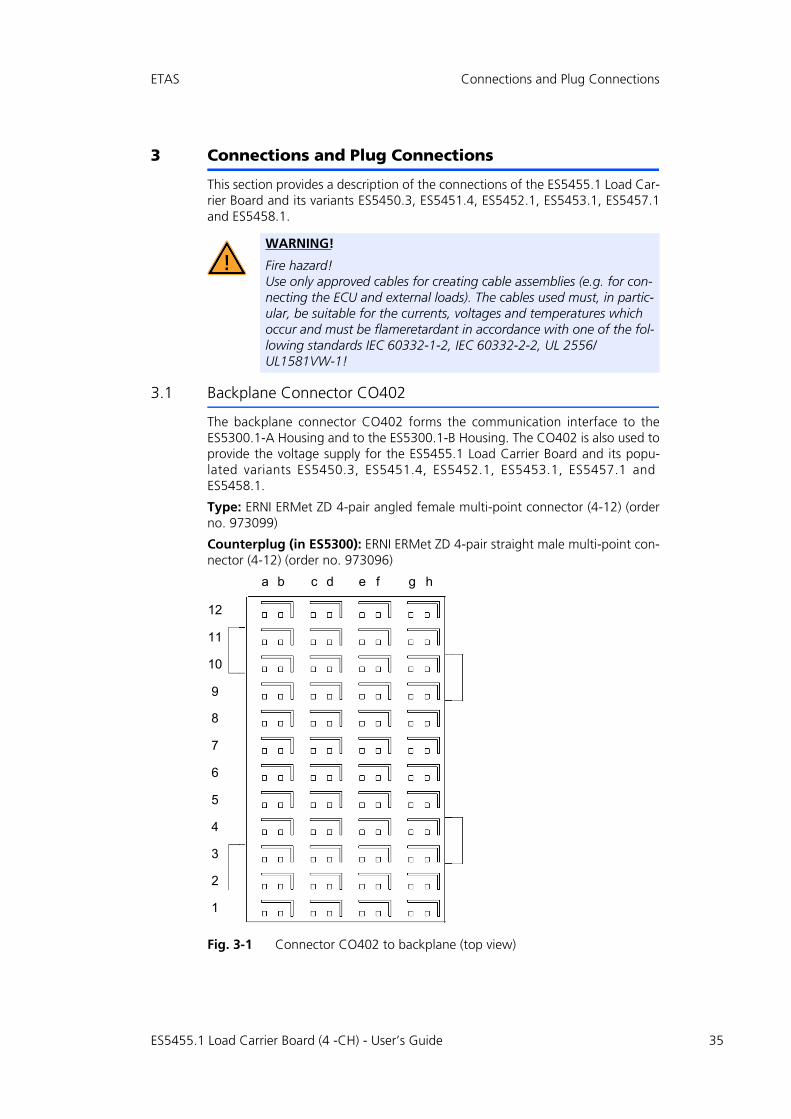
3.1 Backplane Connector CO402
The backplane connector CO402 forms the communication interface to theES5300.1-A Housing and to the ES5300.1-B Housing. The CO402 is also used toprovide the voltage supply for the ES5455.1 Load Carrier Board and its popu-lated variants ES5450.3, ES5451.4, ES5452.1, ES5453.1, ES5457.1 andES5458.1.
Type: ERNI ERMet ZD 4-pair angled female multi-point connector (4-12) (orderno. 973099)
Counterplug (in ES5300): ERNI ERMet ZD 4-pair straight male multi-point con-nector (4-12) (order no. 973096)
Fig. 3-1 Connector CO402 to backplane (top view)
WARNING!
Fire hazard!Use only approved cables for creating cable assemblies (e.g. for con-necting the ECU and external loads). The cables used must, in partic-ular, be suitable for the currents, voltages and temperatures which occur and must be flameretardant in accordance with one of the fol-lowing standards IEC 60332-1-2, IEC 60332-2-2, UL 2556/UL1581VW-1!
12
11
10
9
7
8
6
5
4
3
2
1
hged fba c
ES5455.1 Load Carrier Board (4 -CH) - User’s Guide 35

36
Connections and Plug Connections ETAS
The assignment of the pins is as follows (the maximum possible pin assignmentfor the ES5300.1-A Housing and the ES5300.1-B Housing is indicated here):
ES5455.1 Load Carrier Board (4 -CH) - User’s Guide

ES5455.1 Load Carrier Board (4 -C
H)-
User’s G
uide37
ETAS
Connections and Plug C
onnections
c e a
n_7 M_LVDS_p_7 BN_5 BN_4
GND GND
n_6 M_LVDS_p_6 SPI_CS_B_n SPI_CS_A_n
GND GND
n_5 M_LVDS_p_5 SPI_MOSI SPI_CLK
GND GND
n_4 M_LVDS_p_4 PCIE_WAKEn SPI_MISO
GND GND
n_3 M_LVDS_p_3 n.c. n.c.
GND GND
n_2 M_LVDS_p_2 n.c. n.c.
GND GND
n_1 M_LVDS_p_1 PCIE_JTAG_TCK PCIE_JTAG_TDI
GND GND
n_0 M_LVDS_p_0 PCIE_JTAG_TDO PCIE_JTAG_TMS
GND GND
R_1 GEO_ADDR_0 BN_3 BN_2
GND GND
DAT PCIE_SMBCLK BN_1 BN_0
VCC3_3 VCC3_3
STn PCIE_PRSNT1n PCIE_PRSNT2n_X1
PCIE_PRSNT2n_X4
VCC12 VCC12
2 VCC12 VCC12 VCC12
VCC12 VCC12
h g f e d
12 GBLI_TX_n_0 GBLI_TX_p_0 GBLI_RX_n_0 GBLI_RX_p_0 M_LVDS_
12-shield GND GND
11 GBLI_TX_n_1 GBLI_TX_p_1 GBLI_RX_n_1 GBLI_RX_p_1 M_LVDS_
11-shield GND GND
10 GBLI_TX_n_2 GBLI_TX_p_2 GBLI_RX_n_2 GBLI_RX_p_2 M_LVDS_
10-shield GND GND
9 GBLI_TX_n_3 GBLI_TX_p_3 GBLI_RX_n_3 GBLI_RX_p_3 M_LVDS_
9-shield GND GND
8 GBLI_PRESENT_n GEO_ADDR_4 PCIE_REFCLK_n PCIE_REFCLK_p M_LVDS_
8-shield GND GND
7 PCIE_RX_n_0 PCIE_RX_p_0 PCIE_TX_n_0 PCIE_TX_p_0 M_LVDS_
7-shield GND GND
6 Ass. internally Ass. internally Ass. internally Ass. internally M_LVDS_
6-shield GND GND
5 Ass. internally Ass. internally Ass. internally Ass. internally M_LVDS_
5-shield GND GND
4 Ass. internally Ass. internally IAss. internally Ass. internally GEO_ADD
4-shield GND GND
3 VCC24 VCC24 GEO_ADDR_3 GEO_ADDR_2 PCIE_SMB
3-shield VCC3_3 VCC3_3
2 VSS12 VSS12 VCC3_3 VCC5 PCIE_PER
2-shield VCC12 VCC12
1 VCC3_3 VCC3_3 VCC5 VCC5 VCC1
1-shield VCC12 VCC12

38
Connections and Plug Connections ETAS
3.2 Plug Connector X1
The plug connector X1 enables a connection of the ES5455.1 Load Carrier Boardand its populated variants ES5450.3, ES5451.4, ES5452.1, ES5450.3, ES5457.1and ES5458.1 to an ECU.
Fig. 3-2 Pin numbering of the plug connector X1
The pin assignment for the plug connector X1 is listed in Tab. 3-1 on page 40.
ES5455.1 Load Carrier Board (4 -CH) - User’s Guide

ETAS Connections and Plug Connections
3.2.1 Technical Details of Plug Connector X1
Below is the order information for connectors, counterplugs and crimp contacts.
Type: PCIH47M400A1, maleManufacturer: PositronicOrder number: PCIH47M400A1/AA
Counterplug:
Type: PCIH47F8000, femaleManufacturer: PositronicOrder number: PCIH47F8000/AA
Crimp contacts:
Type: FC422N8Count: 24Manufacturer: PositronicOrder number: FC422N8/AA
Type: FC114N2Count: 23Manufacturer: PositronicOrder number: FC114N2/AA-1565.0
The counterplug and the crimp contacts are part of the scope of supply.
The pin assignment of X1 is as follows:
Note
When crimping the plug contacts of Positronic, use only the crimping tool intended for this purpose.
ES5455.1 Load Carrier Board (4 -CH) - User’s Guide 39

40
Connections and Plug Connections ETAS
-
-
-
-
UT*
UT*
UT*
UT*
UT*
_Ref*
cted
Pin Assignment for X1
Tab. 3-1 Pin assignment for X1
Short name Type # PIN (signal)
PIN (ref.)
Short name
LOAD_0+ Connection for ECU 0 19 17 LOAD_0-
LOAD_1+ Connection for ECU 1 15 13 LOAD_1-
LOAD_2+ Connection for ECU 2 11 9 LOAD_2-
LOAD_3+ Connection for ECU 3 7 5 LOAD_3-
EXT_LOAD_0+ Connection for external load 0 18 20 EXT_LOAD_0
EXT_LOAD_1+ Connection for external load 1 14 16 EXT_LOAD_1
EXT_LOAD_2+ Connection for external load 2 1 3 EXT_LOAD_2
EXT_LOAD_3+ Connection for external load 3 2 4 EXT_LOAD_3
I_DIG_OUT_0 Digital output 0 23 22 GND_DIG_O
I_DIG_OUT_1 Digital output 1 21 22 GND_DIG_O
I_DIG_OUT_2 Digital output 2 26 25 GND_DIG_O
I_DIG_OUT_3 Digital output 3 24 25 GND_DIG_O
28, 31 GND_DIG_O
Online_Probe Analog output 35 34 Online_Probe
NCC_0 Analog output 0 38 37 -VBAT_REF
NCC_1 Analog output 1 39 40 -VBAT_REF
NCC_2 Analog output 2 41 40 -VBAT_REF
NCC_3 Analog output 3 36 37 -VBAT_REF
45, 46, 47
-VBAT
*) The pins 22, 25, 28, 31 GND_DIG_OUT and 34 Online_Probe_Ref are internally conneto each other.
ES5455.1 Load Carrier Board (4 -CH) - User’s Guide

ETAS Connections and Plug Connections
3.2.2 Connecting the NCC Analog Outputs to an ECU
Depending on the requirements of the ECU’s interface, there are different possi-bilities for connecting the NCC analog outputs to an ECU:
• In case each NCC signal shall be analyzed separately, connect each NCC analog output to a separate analog input of the ECU.
• In case the sum signal of two to four NCC/NCS signals shall be analyzed, connect only two or one NCC analog outputs to two or one analog inputs of the ECU.
• In any other case, ask your ETAS contact person for support.
Note
Unlike for the real injectors, the NCC analog output signals of the ES5457.1 can not be added up through parallel connection. Therefore, the sum of the signals is calculated within the FPGA of the ES5457.1 and the sum signal can be output through one single NCC analog output. In this case, ask your ETAS contact person for support.If connected parallel, the NCC analog outputs would interfere with each other.
ES5455.1 Load Carrier Board (4 -CH) - User’s Guide 41

42
Connections and Plug Connections ETAS
3.3 Plug Connector CO1200 on ES5455.1, CO150 and CO100 on the Load Modules
The ES5455.1 Load Carrier Board is connected with the load modules ofES5452.1, ES5453.1, ES5457.1 and ES5458.1 via connector CO1200 and a rib-bon cable. The connectors on the load modules ES5452.1, ES5453.1, ES5457.1and ES5458.1 feature the same type (ES5452.1, ES5453.1, ES5458.1: CO150,ES5457.1: CO100)
Type: SMC-Q 68 M (order no. 244839)
Fig. 3-3 Plug connector CO1200 on the ES5455.1 Load Carrier Board, CO150 on the load module of ES5452.1, ES5453.1, ES5458.1 and CO100 on the load module of ES5457.1
ES5455.1 Load Carrier Board (4 -CH) - User’s Guide

ETAS Technical Data and Standards
4 Technical Data and Standards
This chapter contains the technical data of the ES5455.1 Load Carrier Board andits populated variants ES5450.3, ES5451.4, ES5452.1, ES5450.3, ES5457.1 andES5458.1 and the applicable standards.
4.1 Technical Data
Plug Connector X1
Voltage Supply (Backplane Connector)
Pins 1-20, 45,46,47 (load channels)
Abs. max. load current ±20 A for max. 1 ms
Abs. max. load voltage per channel ±60 V DC for max. 1 ms
Abs. max. duty cycle 25%
Max. power 50 W rms (root meansquare)
Pins 21-44
Electric strength of outputs ±60 V DC
Current rating of connections ±1 A
Output voltage analog outputs -10 V bis +10 V
Output voltage digital outputs 0 V bis 15 V
Accuracy of current measurement - Level
±3%
Accuracy of current measurement - Timing
±2%
CAUTION!
The absolute maximum load current, absolute maximum load volt-age, absolute maximum duty cycle and maximum permissible power of 50 W rms must not be exceeded. If one or several of these values are exceeded, the ES5455.1 Load Carrier Board and its variants ES5450.3, ES5451.4, ES5452.1, ES5453.1, ES5457.1 and ES5458.1 can be damaged, or an undefined behavior can occur (e.g. emer-gency shutdown of injector load).
Max. permissible power consumption from backplane 25 W at 12 V DC4 W at 5 V DC8 W at 3,3 V DC
ES5455.1 Load Carrier Board (4 -CH) - User’s Guide 43
44
Technical Data and Standards ETAS
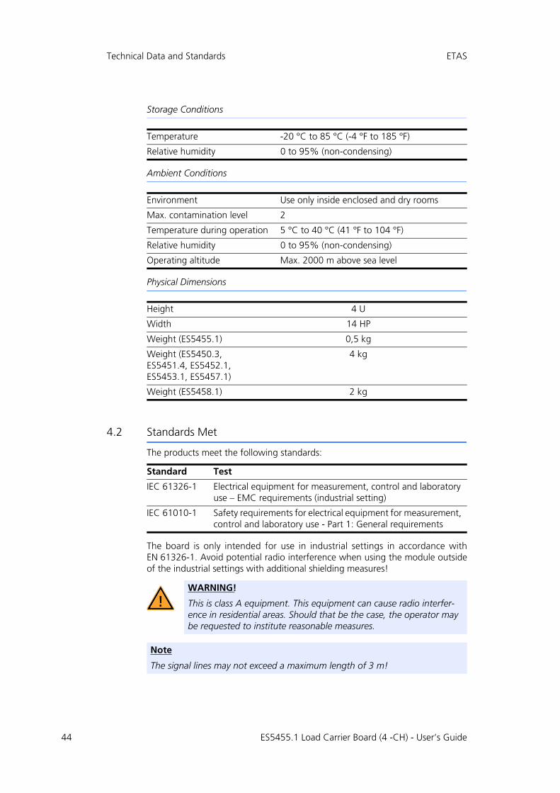
Storage Conditions
Ambient Conditions
Physical Dimensions
4.2 Standards Met
The products meet the following standards:
The board is only intended for use in industrial settings in accordance withEN 61326-1. Avoid potential radio interference when using the module outsideof the industrial settings with additional shielding measures!
Temperature -20 °C to 85 °C (-4 °F to 185 °F)
Relative humidity 0 to 95% (non-condensing)
Environment Use only inside enclosed and dry rooms
Max. contamination level 2
Temperature during operation 5 °C to 40 °C (41 °F to 104 °F)
Relative humidity 0 to 95% (non-condensing)
Operating altitude Max. 2000 m above sea level
Height 4 U
Width 14 HP
Weight (ES5455.1) 0,5 kg
Weight (ES5450.3, ES5451.4, ES5452.1, ES5453.1, ES5457.1)
4 kg
Weight (ES5458.1) 2 kg
Standard Test
IEC 61326-1 Electrical equipment for measurement, control and laboratory use – EMC requirements (industrial setting)
IEC 61010-1 Safety requirements for electrical equipment for measurement, control and laboratory use - Part 1: General requirements
WARNING!
This is class A equipment. This equipment can cause radio interfer-ence in residential areas. Should that be the case, the operator may be requested to institute reasonable measures.
Note
The signal lines may not exceed a maximum length of 3 m!
ES5455.1 Load Carrier Board (4 -CH) - User’s Guide

ETAS Ordering Data
5 Ordering Data
The ordering data for the are as follows:
Scope of delivery for the ES5455.1 Load Carrier Board and its variants ES5450.3,ES5451.4, ES5452.1, ES5453.1, ES5457.1 and ES5458.1:
Order name Short name Order number
ES5455.1 Load Carrier Board ES5455.1 F-00K-111-358
ES5450.3 Load Carrier Board for 4 RB CRI2x Injectors
ES5450.3 F-00K-111-359
ES5451.4 Load Carrier Board for 4 RB HDEV5 Injectors
ES5451.4 F-00K-111-362
ES5452.1 Load Carrier Board for 4 RB HDEV5 Injectors, CVO
ES5452.1 F-00K-111-363
ES5453.1 Load Carrier Board for 4 RB HDEV6 Injectors, CVO
ES5453.1 F-00K-111-364
ES5457.1 Load Carrier Board for 4 RB CRI2x Injectors, VCC
ES5457.1 F-00K-111-365
ES5458.1 Load Carrier Board for 4 RB PFI EV14 Injectors, CVO
ES5458.1 F-00K-111-366
Calibration Service for ES5450 K_ES5450 F-00K-111-673
Calibration Service for ES5451 K_ES5451 F-00K-111-674
Calibration Service for ES5452 K_ES5452 F-00K-111-675
Calibration Service for ES5453 K_ES5453 F-00K-111-676
Calibration Service for ES5455 K_ES5455 F-00K-111-672
Calibration Service for ES5457 K_ES5457 F-00K-111-677
Calibration Service for ES5458 K_ES5458 F-00K-111-678
Scope of delivery Number of pieces Order number
The respective board 1 see table above
Additional smaller front plate for ES5455.1
1
Counter plug:Type: PCIH47F8000, femaleManufacturer: Positronic
1 PCIH47F8000/AA
Crimp contacts Type: FC422N8Manufacturer: Positronic
24 FC422N8/AA
Crimp contactsType: FC114N2Manufacturer: Positronic
23 FC114N2/AA-1565.0
ES5455.1 Load Carrier Board (4 -CH) - User’s Guide 45

46
Ordering Data ETAS
ES5455.1 Load Carrier Board (4 -CH) - User’s Guide

ETAS ETAS Contact Addresses
6 ETAS Contact Addresses
ETAS HQ
ETAS GmbH
ETAS Subsidiaries and Technical Support
For details of your local sales office as well as your local technical support teamand product hotlines, take a look at the ETAS website:
Borsigstraße 24 Phone: +49 711 3423-0
70469 Stuttgart Fax: +49 711 3423-2106
Germany WWW: www.etas.com
ETAS subsidiaries WWW: www.etas.com/en/contact.php
ETAS technical support WWW: www.etas.com/en/hotlines.php
ES5455.1 Load Carrier Board (4-CH) - User’s Guide 47

48
ETAS Contact Addresses ETAS
ES5455.1 Load Carrier Board (4-CH) - User’s Guide

ETAS Index
Index
AAccident prevention 10BBasic safety notices 9Block diagram 21
CCE Declaration of Conformity 16Connecting devices 14Connections and Connectors 35
Backplane connector CO402 35X1 Measure 38X2 Load 38
DDefibrillators 15Devices
Connecting 14
EElectrical safety 11ETAS Contact Addresses 47
FFront plate 23
GGeneral safety information 9
IIdentification of safety notices 9Identifications on the product 15Improper use 9Injector simulation environment 21Intended 10Intended use 11Interface for load modules 32
LLABCAR HiL system 22
OOrdering data 45
PPacemaker 15Piezo signal generator 32Product return 17Properties 6, 7
QQualification, required 9
RRecycling 17Removal 29RoHS conformity
China 16European Union 16
ES5455.1 Load Carrier Board (4 -CH) - User’s Guide 49

50
Index ETAS
SSafety at work 10, 11Safety precautions 9Signal lines 44Simulation environment 21Standards 43, 44Storage conditions 44
TTechnical Data 43
WWaste Electrical and Electronic Equip-
ment 17WEEE return system 17
ES5455.1 Load Carrier Board (4 -CH) - User’s Guide