Embed Size (px)
Citation preview

ES313.1 A/D Module with Sensor Supply (4 CH)ES314.1 A/D Module with Sensor Supply (8 CH)User’s Guide

2
Copyright
The data in this document may not be altered or amended without special noti-fication from ETAS GmbH. ETAS GmbH undertakes no further obligation in rela-tion to this document. The software described in it can only be used if thecustomer is in possession of a general license agreement or single license. Usingand copying is only allowed in concurrence with the specifications stipulated inthe contract.
Under no circumstances may any part of this document be copied, reproduced,transmitted, stored in a retrieval system or translated into another languagewithout the express written permission of ETAS GmbH.
© Copyright 2018 ETAS GmbH, Stuttgart
The names and designations used in this document are trademarks or brandsbelonging to the respective owners.
ES31x.1 User’s Guide R03 EN - 04.2018
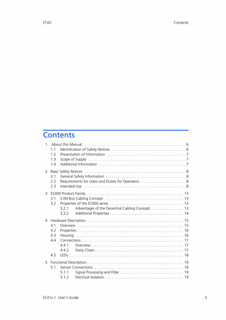
Contents
ETAS Contents
1 About this Manual . . . . . . . . . . . . . . . . . . . . . . . . . . . . . . . . . . . . . . . . . . . . . . . . . 61.1 Identification of Safety Notices . . . . . . . . . . . . . . . . . . . . . . . . . . . . . . . . . . . 61.2 Presentation of Information . . . . . . . . . . . . . . . . . . . . . . . . . . . . . . . . . . . . . 71.3 Scope of Supply . . . . . . . . . . . . . . . . . . . . . . . . . . . . . . . . . . . . . . . . . . . . . . 71.4 Additional Information . . . . . . . . . . . . . . . . . . . . . . . . . . . . . . . . . . . . . . . . . 7
2 Basic Safety Notices . . . . . . . . . . . . . . . . . . . . . . . . . . . . . . . . . . . . . . . . . . . . . . . . 82.1 General Safety Information . . . . . . . . . . . . . . . . . . . . . . . . . . . . . . . . . . . . . . 82.2 Requirements for Users and Duties for Operators . . . . . . . . . . . . . . . . . . . . . 82.3 Intended Use . . . . . . . . . . . . . . . . . . . . . . . . . . . . . . . . . . . . . . . . . . . . . . . . 8
3 ES300 Product Family . . . . . . . . . . . . . . . . . . . . . . . . . . . . . . . . . . . . . . . . . . . . . . 133.1 CAN Bus Cabling Concept . . . . . . . . . . . . . . . . . . . . . . . . . . . . . . . . . . . . . 133.2 Properties of the ES300 series . . . . . . . . . . . . . . . . . . . . . . . . . . . . . . . . . . . 13
3.2.1 Advantages of the Decentral Cabling Concept. . . . . . . . . . . . . . . . 133.2.2 Additional Properties . . . . . . . . . . . . . . . . . . . . . . . . . . . . . . . . . . . 14
4 Hardware Description . . . . . . . . . . . . . . . . . . . . . . . . . . . . . . . . . . . . . . . . . . . . . . 154.1 Overview . . . . . . . . . . . . . . . . . . . . . . . . . . . . . . . . . . . . . . . . . . . . . . . . . . 154.2 Properties . . . . . . . . . . . . . . . . . . . . . . . . . . . . . . . . . . . . . . . . . . . . . . . . . . 164.3 Housing . . . . . . . . . . . . . . . . . . . . . . . . . . . . . . . . . . . . . . . . . . . . . . . . . . . 164.4 Connections . . . . . . . . . . . . . . . . . . . . . . . . . . . . . . . . . . . . . . . . . . . . . . . . 17
4.4.1 Overview. . . . . . . . . . . . . . . . . . . . . . . . . . . . . . . . . . . . . . . . . . . . 174.4.2 Daisy Chain . . . . . . . . . . . . . . . . . . . . . . . . . . . . . . . . . . . . . . . . . . 17
4.5 LEDs . . . . . . . . . . . . . . . . . . . . . . . . . . . . . . . . . . . . . . . . . . . . . . . . . . . . . . 18
5 Functional Description. . . . . . . . . . . . . . . . . . . . . . . . . . . . . . . . . . . . . . . . . . . . . . 195.1 Sensor Connections . . . . . . . . . . . . . . . . . . . . . . . . . . . . . . . . . . . . . . . . . . 19
5.1.1 Signal Processing and Filter . . . . . . . . . . . . . . . . . . . . . . . . . . . . . . 195.1.2 Electrical Isolation . . . . . . . . . . . . . . . . . . . . . . . . . . . . . . . . . . . . . 19
ES31x.1 User’s Guide 3
4
Contents ETAS
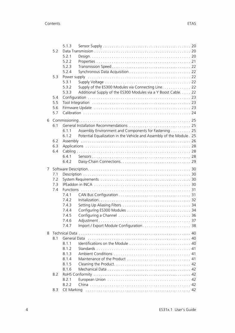
5.1.3 Sensor Supply . . . . . . . . . . . . . . . . . . . . . . . . . . . . . . . . . . . . . . . . 205.2 Data Transmission . . . . . . . . . . . . . . . . . . . . . . . . . . . . . . . . . . . . . . . . . . . . 20
5.2.1 Design. . . . . . . . . . . . . . . . . . . . . . . . . . . . . . . . . . . . . . . . . . . . . . 205.2.2 Properties . . . . . . . . . . . . . . . . . . . . . . . . . . . . . . . . . . . . . . . . . . . 215.2.3 Transmission Speed . . . . . . . . . . . . . . . . . . . . . . . . . . . . . . . . . . . . 225.2.4 Synchronous Data Acquisition . . . . . . . . . . . . . . . . . . . . . . . . . . . . 22
5.3 Power supply . . . . . . . . . . . . . . . . . . . . . . . . . . . . . . . . . . . . . . . . . . . . . . . 225.3.1 Supply Voltage . . . . . . . . . . . . . . . . . . . . . . . . . . . . . . . . . . . . . . . 225.3.2 Supply of the ES300 Modules via Connecting Line. . . . . . . . . . . . . 225.3.3 Additional Supply of the ES300 Modules via a Y Boost Cable. . . . . 22
5.4 Configuration . . . . . . . . . . . . . . . . . . . . . . . . . . . . . . . . . . . . . . . . . . . . . . . 235.5 Tool Integration . . . . . . . . . . . . . . . . . . . . . . . . . . . . . . . . . . . . . . . . . . . . . 235.6 Firmware Update . . . . . . . . . . . . . . . . . . . . . . . . . . . . . . . . . . . . . . . . . . . . 235.7 Calibration . . . . . . . . . . . . . . . . . . . . . . . . . . . . . . . . . . . . . . . . . . . . . . . . . 24
6 Commissioning . . . . . . . . . . . . . . . . . . . . . . . . . . . . . . . . . . . . . . . . . . . . . . . . . . . 256.1 General Installation Recommendations . . . . . . . . . . . . . . . . . . . . . . . . . . . . 25
6.1.1 Assembly Environment and Components for Fastening . . . . . . . . . 256.1.2 Potential Equalization in the Vehicle and Assembly of the Module . 25
6.2 Assembly . . . . . . . . . . . . . . . . . . . . . . . . . . . . . . . . . . . . . . . . . . . . . . . . . . 266.3 Applications . . . . . . . . . . . . . . . . . . . . . . . . . . . . . . . . . . . . . . . . . . . . . . . . 286.4 Cabling . . . . . . . . . . . . . . . . . . . . . . . . . . . . . . . . . . . . . . . . . . . . . . . . . . . . 28
6.4.1 Sensors . . . . . . . . . . . . . . . . . . . . . . . . . . . . . . . . . . . . . . . . . . . . . 286.4.2 Daisy-Chain Connections. . . . . . . . . . . . . . . . . . . . . . . . . . . . . . . . 29
7 Software Description. . . . . . . . . . . . . . . . . . . . . . . . . . . . . . . . . . . . . . . . . . . . . . . 307.1 Description . . . . . . . . . . . . . . . . . . . . . . . . . . . . . . . . . . . . . . . . . . . . . . . . . 307.2 System Requirements . . . . . . . . . . . . . . . . . . . . . . . . . . . . . . . . . . . . . . . . . 307.3 IPEaddon in INCA . . . . . . . . . . . . . . . . . . . . . . . . . . . . . . . . . . . . . . . . . . . . 307.4 Functions . . . . . . . . . . . . . . . . . . . . . . . . . . . . . . . . . . . . . . . . . . . . . . . . . . 31
7.4.1 CAN Bus Configuration . . . . . . . . . . . . . . . . . . . . . . . . . . . . . . . . . 317.4.2 Initialization. . . . . . . . . . . . . . . . . . . . . . . . . . . . . . . . . . . . . . . . . . 327.4.3 Setting Up Aliasing Filters . . . . . . . . . . . . . . . . . . . . . . . . . . . . . . . 347.4.4 Configuring ES300 Modules . . . . . . . . . . . . . . . . . . . . . . . . . . . . . 347.4.5 Configuring a Channel . . . . . . . . . . . . . . . . . . . . . . . . . . . . . . . . . 367.4.6 Adjustment . . . . . . . . . . . . . . . . . . . . . . . . . . . . . . . . . . . . . . . . . . 377.4.7 Import / Export Module Configuration . . . . . . . . . . . . . . . . . . . . . . 38
8 Technical Data . . . . . . . . . . . . . . . . . . . . . . . . . . . . . . . . . . . . . . . . . . . . . . . . . . . 408.1 General Data . . . . . . . . . . . . . . . . . . . . . . . . . . . . . . . . . . . . . . . . . . . . . . . 40
8.1.1 Identifications on the Module . . . . . . . . . . . . . . . . . . . . . . . . . . . . 408.1.2 Standards . . . . . . . . . . . . . . . . . . . . . . . . . . . . . . . . . . . . . . . . . . . 418.1.3 Ambient Conditions . . . . . . . . . . . . . . . . . . . . . . . . . . . . . . . . . . . 418.1.4 Maintenance of the Product . . . . . . . . . . . . . . . . . . . . . . . . . . . . . 418.1.5 Cleaning the Product. . . . . . . . . . . . . . . . . . . . . . . . . . . . . . . . . . . 428.1.6 Mechanical Data . . . . . . . . . . . . . . . . . . . . . . . . . . . . . . . . . . . . . . 42
8.2 RoHS Conformity . . . . . . . . . . . . . . . . . . . . . . . . . . . . . . . . . . . . . . . . . . . . 428.2.1 European Union . . . . . . . . . . . . . . . . . . . . . . . . . . . . . . . . . . . . . . 428.2.2 China . . . . . . . . . . . . . . . . . . . . . . . . . . . . . . . . . . . . . . . . . . . . . . 42
8.3 CE Marking . . . . . . . . . . . . . . . . . . . . . . . . . . . . . . . . . . . . . . . . . . . . . . . . 42
ES31x.1 User’s Guide

ETAS Contents
8.4 Product Return and Recycling . . . . . . . . . . . . . . . . . . . . . . . . . . . . . . . . . . . 428.5 Materials Subject to Declaration . . . . . . . . . . . . . . . . . . . . . . . . . . . . . . . . . 438.6 System Requirements . . . . . . . . . . . . . . . . . . . . . . . . . . . . . . . . . . . . . . . . . 43
8.6.1 Hardware . . . . . . . . . . . . . . . . . . . . . . . . . . . . . . . . . . . . . . . . . . . 438.6.2 Software . . . . . . . . . . . . . . . . . . . . . . . . . . . . . . . . . . . . . . . . . . . . 43
8.7 Electrical Data . . . . . . . . . . . . . . . . . . . . . . . . . . . . . . . . . . . . . . . . . . . . . . . 448.7.1 Voltage Supply . . . . . . . . . . . . . . . . . . . . . . . . . . . . . . . . . . . . . . . 448.7.2 Host Interface . . . . . . . . . . . . . . . . . . . . . . . . . . . . . . . . . . . . . . . . 448.7.3 Sensor Power Supply . . . . . . . . . . . . . . . . . . . . . . . . . . . . . . . . . . . 448.7.4 Sensor Inputs . . . . . . . . . . . . . . . . . . . . . . . . . . . . . . . . . . . . . . . . 458.7.5 Signal Processing . . . . . . . . . . . . . . . . . . . . . . . . . . . . . . . . . . . . . . 46
8.8 Terminal Assignment . . . . . . . . . . . . . . . . . . . . . . . . . . . . . . . . . . . . . . . . . 468.8.1 LEMO CAN Bus . . . . . . . . . . . . . . . . . . . . . . . . . . . . . . . . . . . . . . . 468.8.2 LEMO Sensor. . . . . . . . . . . . . . . . . . . . . . . . . . . . . . . . . . . . . . . . . 47
9 Cables and Accessories . . . . . . . . . . . . . . . . . . . . . . . . . . . . . . . . . . . . . . . . . . . . . 489.1 Measurement Cables . . . . . . . . . . . . . . . . . . . . . . . . . . . . . . . . . . . . . . . . . 489.2 Combined CAN Connection and Power Supply Cable . . . . . . . . . . . . . . . . . 49
9.2.1 CBCP300.1 . . . . . . . . . . . . . . . . . . . . . . . . . . . . . . . . . . . . . . . . . . 499.2.2 CBCP3005.1 . . . . . . . . . . . . . . . . . . . . . . . . . . . . . . . . . . . . . . . . . 499.2.3 CBCP301.1 . . . . . . . . . . . . . . . . . . . . . . . . . . . . . . . . . . . . . . . . . . 509.2.4 CBCP3015.1 . . . . . . . . . . . . . . . . . . . . . . . . . . . . . . . . . . . . . . . . . 50
9.3 CAN Chain Connection Cable . . . . . . . . . . . . . . . . . . . . . . . . . . . . . . . . . . . 519.4 CAN Termination Resistor Plug . . . . . . . . . . . . . . . . . . . . . . . . . . . . . . . . . . 519.5 Mounting Bracket . . . . . . . . . . . . . . . . . . . . . . . . . . . . . . . . . . . . . . . . . . . . 51
10 Ordering Information . . . . . . . . . . . . . . . . . . . . . . . . . . . . . . . . . . . . . . . . . . . . . . 5210.1 ES313.1 . . . . . . . . . . . . . . . . . . . . . . . . . . . . . . . . . . . . . . . . . . . . . . . . . . . 5210.2 ES314.1 . . . . . . . . . . . . . . . . . . . . . . . . . . . . . . . . . . . . . . . . . . . . . . . . . . . 5210.3 Accessories . . . . . . . . . . . . . . . . . . . . . . . . . . . . . . . . . . . . . . . . . . . . . . . . . 53
10.3.1 Cables . . . . . . . . . . . . . . . . . . . . . . . . . . . . . . . . . . . . . . . . . . . . . . 5310.3.2 Can Termination Resistor Plug . . . . . . . . . . . . . . . . . . . . . . . . . . . . 5410.3.3 Mounting Bracket . . . . . . . . . . . . . . . . . . . . . . . . . . . . . . . . . . . . . 5410.3.4 Calibration Service. . . . . . . . . . . . . . . . . . . . . . . . . . . . . . . . . . . . . 54
11 ETAS Contact Addresses . . . . . . . . . . . . . . . . . . . . . . . . . . . . . . . . . . . . . . . . . . . . 55
Figures . . . . . . . . . . . . . . . . . . . . . . . . . . . . . . . . . . . . . . . . . . . . . . . . . . . . . . . . . 56
Index . . . . . . . . . . . . . . . . . . . . . . . . . . . . . . . . . . . . . . . . . . . . . . . . . . . . . . . . . . 57
ES31x.1 User’s Guide 5

6
About this Manual ETAS
1 About this Manual
This chapter contains information about the following topics:
• "Identification of Safety Notices" on page 6
• "Presentation of Information" on page 7
• "Scope of Supply" on page 7
• "Additional Information" on page 7.
1.1 Identification of Safety Notices
The safety notices contained in this manual are identified with the danger symbolshown below:
The safety notices shown below are used for this purpose. They provide notes toextremely important information. Please read this information carefully.
DANGER!
indicates an immediate danger with a high risk of death or serious injury, if not avoided.
WARNING!
indicates a possible danger with moderate risk of death or (serious) injury, if not avoided.
CAUTION!
identifies a hazard with low risk that could result in minor or medium physical injuries or property damages if not avoided.
ES31x.1 User’s Guide

ETAS About this Manual
1.2 Presentation of Information
All activities to be performed by the user are presented in a "Use Case" format.That is, the goal to be accomplished is briefly defined in the heading, and therespective steps required for reaching this goal are then presented in a list. Thepresentation looks as follows:
Goal definition:
any advance information...
1. Step 1
Any explanation for step 1...
2. Step 2
Any explanation for step 2...
3. Step 3
Any explanation for step 3...
Any concluding comments...
Typographical conventions
The following typographical conventions are used:
Other conventions
• Select Database New means, "Select the ’New’ button menu item from the ’Database’ menu".
• Click on OK means, "Click on the ’OK’ button".
Important notes for the user are presented as follows:
1.3 Scope of Supply
Prior to the initial commissioning of the module, please check whether the mod-ule was delivered with all required components and cables (see chapter 10on page 52).
Additional cables and adapters can be obtained separately from ETAS. A list ofavailable accessories and their order designation is located in chapter 10on page 52 of this manual or in the ETAS product catalog.
1.4 Additional Information
The configuration instructions for the module under INCA can be found in thecorresponding software documentation.
Bold Labels of the device
Italic Particularly important text passages
Note
Important note for the user.
ES31x.1 User’s Guide 7

8
Basic Safety Notices ETAS
2 Basic Safety Notices
This chapter contains information about the following topics:
• "General Safety Information" on page 8
• "Requirements for Users and Duties for Operators" on page 8
• "Intended Use" on page 8.
2.1 General Safety Information
Please observe the Product Safety Notices ("ETAS Safety Notice") and the follow-ing safety notices to avoid health issues or damage to the device.
ETAS GmbH does not assume any liability for damages resulting from improperhandling, unintended use or non-observance of the safety precautions.
2.2 Requirements for Users and Duties for Operators
The product may be assembled, operated and maintained only if you have thenecessary qualification and experience for this product. Improper use or use by auser without sufficient qualification can lead to damages or injuries to one’shealth or damage to property.The system integrator is responsible for the safety of systems that use the prod-uct.
General safety at work
Existing specifications regarding health and safety and accident prevention mustbe observed. All applicable regulations and statutes regarding operation must bestrictly followed when using this product.
2.3 Intended Use
Application area of the product
This product was developed and approved for applications in the automotivesector. The module is suitable for use in the engine compartment of vehicles.
For use in other application areas, please contact your ETAS contact partner.
Requirements for the technical state of the product
The product is designed in accordance with state-of-the-art technology and rec-ognized safety rules. The product may be operated only in a technically flawlesscondition and according to the intended purpose and with regard to safety anddangers as stated in the respective product documentation. If the product is notused according to its intended purpose, the protection of the product may beimpaired.
Note
Carefully read the documentation (Product Safety Advice and this User's Guide) that belongs to the product prior to the startup.
ES31x.1 User’s Guide

ETAS Basic Safety Notices
Requirements for operation
• Use the product only according with the specifications in the relevant User's Guide. Any other usage could jeopardize product safety.
• Observe the requirements on the ambient conditions.
• Do not use the product in potentially explosive areas.
Electrical safety and power supply
• Please comply with all electrical safety regulations and all health and safety laws and specifications valid at the place of use!
• Connect only current circuits with safety extra-low voltage in accordance with EN 61140 (degree of protection III) to the connections of the module.
• Ensure the compliance with the connection and adjustment values (see the information in the chapter 8 on page 40).
• Do not apply any voltages to the connections of the module that do not correspond to the specifications of the respective connection.
Power supply
• The power supply for the product must be safely disconnected from the supply voltage. For example, use a car battery or a suitable lab power sup-ply.
• Use exclusively lab power supplies with double protection to the supply system (with double insulation / with reinforced insulation (DI / RI)).
• The lab power supply must be approved for an operating altitude of 3,000 m / 9,842 ft. and for an ambient temperature of up to 105 °C.
• The vehicle battery could be discharged when the modules are in opera-tion.
CAUTION!
Risk of burning on hot surfaces of the module!Do not touch the surfaces of the module during operation at high ambient temperatures.The surface temperature of the module can reach 90 °C when it is used in a vehicle and at an ambient temperature of 70 °C.
ES31x.1 User’s Guide 9

10
Basic Safety Notices ETAS
Connection to the power supply
• The power supply cable must not be directly connected to the vehicle bat-tery or lab power supply, but rather via a suitable protection mechanism.
• Make sure the connections to the lab power supply, the power supply on the module and on the vehicle battery are easily accessible!
• Route the power cord in such a way that it is protected against abrasion, damages, deformation and kinking!
• Do not place any objects on the power cord!
De-energizing the module
The module does not have a power switch. The module can be de-energized asfollows:
• Disconnecting the cables from the measurement inputs
and
• Disconnecting the module from the power supply
– Switching off the lab power supply
or
– Disconnecting the module from the lab power supply
Disconnect device is the lab connector on the power supply cable or the plug on the power supply cable at the module connection
or
Disconnect device is the lab connector on the power supply cable or the plug on the power supply cable at the module connection
or
– Disconnecting the vehicle battery.
DANGER!
Dangerous electrical voltage!Only connect the power supply cable to a suitable vehicle battery or a suitable lab power supply! Connecting to a mains socket is not allowed!To prevent the connector from accidentally being plugged into a mains socket, ETAS recommends using power supply cables with safety banana plugs in areas with mains sockets..
ES31x.1 User’s Guide

ETAS Basic Safety Notices
Cabling
Approved cables:
• Use exclusively ETAS cables at the connections of the module!
• Adhere to the maximum permissible cable lengths!
• Do not use any damaged cables! Cables may be repaired only by ETAS!
Requirements for the place of installation
• Place the module or the module block on a smooth, even and firm foun-dation.
• The module or module block must always be securely fixed.
Requirements on the ventilation
• Keep the module away from heat sources and protect it against direct exposure to the sun.
• The free space above and behind the module must be selected so that sufficient air circulation is ensured.
Fixing the module on a carrier system
When selecting the carrier system, note the static and dynamic forces whichcould occur as a result of the module or module block on the carrier system.
CAUTION!
Never apply force to insert a plug into a socket.Ensure that there is no contamination in and on the connection, that the plug fits the socket, and that you correctly aligned the plugs with the connection.
CAUTION!
Potential equalization in the vehicle is possible via the shield of the connecting cables of the modules!Install the modules only at locations with the same electrical potential or isolate the modules from the installation location.
CAUTION!
Damage or destruction of the module is possible.Risk of damage or destruction of the modules. Modules of the ES300 series are only approved for installation and operation on compo-nents or at places where compliance with the technical data of the module is guaranteed, e.g.:
• vibration resistance of modules (for example, modules only mounted on sprung masses, but not on wheel suspensions or directly on the engine) and
• temperature resistance of modules (for example, modules not mounted on the engine, turbocharger, exhaust manifold or their immediate surrounds).
ES31x.1 User’s Guide 11

12
Basic Safety Notices ETAS
Damage of the product and loss of properties in accordance with IP67
Transport
• Do not block and connect the modules until they are at their commission-ing location!
• Do not transport the modules at the cable of the module or any other cables.
Maintenance
The product is maintenance-free.
Repair
If an ETAS hardware product should require a repair, return the product to ETAS.
Cleaning the module housing
• Use a dry or lightly moistened, soft, lint-free cloth for cleaning the module housing.
• Do not use any sprays, solvents or abrasive cleaners which could damage the housing.
• Ensure that no moisture enters the housing. Never spray cleaning agents directly onto the module.
CAUTION!
During the installation of the modules, note the permissible tempera-ture range of the cable ties used!
CAUTION!
Loss of properties in accordance with IP67!Do not open or modify the product housing.Work on the product housing may be performed only by qualified technical personnel.
ES31x.1 User’s Guide

ETAS ES300 Product Family
3 ES300 Product Family
This chapter contains information about the following topics:
• "CAN Bus Cabling Concept" on page 13
• "Properties of the ES300 series" on page 13
3.1 CAN Bus Cabling Concept
In a test vehicle, several hundred sensors must be installed in many areas for thetesting phase, e.g. in the engine compartment and in the ground area. The sen-sors distributed over the entire vehicle must then be connected with the measur-ing devices of the test setup.
Today's standard solutions with a central setup of the measuring devices in thepassenger compartment require a complex cabling of the widely distributed sen-sors with the measuring devices. Numerous, mostly long connecting cablesbetween sensors and measuring devices, combined into several thick cable har-nesses, demand a heavily modified fire wall of the test vehicle. This causes longsetup times and high costs.
With the ES300 modules, ETAS offers a decentral solution that significantly sim-plifies the measuring set-up of the sensors.
The basic idea of this concept is to install the modules of the ES300 series spa-tially as close as possible to the sensors, to chain the modules with each otherand to connect only the first module of this chain with the laptop in the vehicle.
The ES300 modules from ETAS are independent measuring modules that passthe measuring signals over the CAN bus. They can be operated individually aswell as in combination with other modules from ETAS.
3.2 Properties of the ES300 series
3.2.1 Advantages of the Decentral Cabling Concept
• The compact ES300 modules can be installed close to the sensors with short connecting cables.
• The simple assembly and cabling principle (daisy-chain topology) of the modules
– requires only on common cable between the modules for the power supply and the transmission of data,
– significantly reduces the setup times for the tests, and
– simplifies the maintenance and expansion of the measuring setup.
• Only the laptop has to be accommodated in the vehicle, which is con-nected with the modules using a single cable.
• Test vehicles equipped with a ES300 measuring system can be used in a flexible way since the vehicles do not have to be modified for changed or new test assignments.
ES31x.1 User’s Guide 13

14
ES300 Product Family ETAS
3.2.2 Additional Properties
In addition to the advantages of the decentral cabling, additional properties ofthe ES300 series are provided here at a glance:
• The design of the ES300 modules is very compact.
• Each of the modules features an LED for localizing the module.
• Automotive-qualified modules that are suitable for use in the lab and in the vehicle on test tracks:
– Housing, connections and cables water-proof and dust-proof to IP67, designed for use in the engine compartment of the vehicle.
– Robust to accelerations and mechanical damages
– Robust to ambient conditions (temperature, humidity, EMC)
– Very low temperature coefficients contribute to a reduction in measur-ing errors.
• All channels fully electrically isolated
• Dovetailing for tool-free module connection of the ES300 modules
• Different channel sampling rates
• Part of the ETAS Tool Suite
The complete technical data is located in chapter 8 on page 40.
ES31x.1 User’s Guide

ETAS Hardware Description
4 Hardware Description
This chapter contains information about the following topics:
• "Overview" on page 15
• "Properties" on page 16
• "Housing" on page 16
• "Connections" on page 17
• "LEDs" on page 18
4.1 Overview
Fig. 4-1 Housing ES313.1 (above) and ES314.1 (below)
The A/D modules with sensor supply ES313.1 and ES314.1 are part of the seriesof ES300 modules. The ES31x can record analog voltages, currents and sensorsignals at 4 respectively 8 input channels. A sensor supply is available for eachchannel.
ES31x.1 User’s Guide 15

16
Hardware Description ETAS
4.2 Properties
• 4 respectively 8 electrically isolated A/D channels, separately configurable
• Measure range from 100 mV to 60 V
• Sample rate from 1 Hz to 2,000 kHz (measuring and calibrating)
• Adjustable short circuit-proof sensor supply voltage (2.5 V to 15 V)
The complete technical data of the ES313.1 and ES314.1 is located in chapter 8on page 40.
4.3 Housing
The ES31x utilizes a robust metal housing with connections at the front of theunit. The ES31x is designed for installation in the engine compartment.
The housings of the ES300 series can be connected with each other quickly andeasily to form a measuring system (see chapter 6 on page 25). In the vehicle or inthe lab, the modules can be screwed directly onto a carrier system without mucheffort or fastened with cable ties.
These simple and uncomplicated fastening options allow for a flexible assemblyof the modules. On top of that, a high degree of availability of the fasteningoptions is also given under rough harsh ambient conditions (salt mist, dirt).
CAUTION!
Loss of Properties after IP67!Do not open or change the module housing!Work on the module housing may only be performed by ETAS.
ES31x.1 User’s Guide

ETAS Hardware Description
4.4 Connections
4.4.1 Overview
All plug connections of the ES300 modules are located on the front (see Fig. 4-2).
Fig. 4-2 Connections ES313.1 (above) and ES314.1 (below)
The LEMO plug connectors used are installed in accordance with degree of pro-tection IP67.
4.4.2 Daisy Chain
The modules are connected using a daisy-chain topology. The input and outputsockets are freely selectable. The CAN data line and the voltage supply arelooped through the daisy-chain connections of the module.
One connection is connected to the bus interface module. The other connectionis connected with the following module of the ES300 series or the CAN terminat-ing resistor is connected to the connection at the last module of the chain.
No. in Fig. 4-2 Connection Meaning
1 LEMO Measurement input
2 LEMO CAN bus and power supply
ES31x.1 User’s Guide 17

18
Hardware Description ETAS
4.5 LEDs
The ES313.1 features a status LED for the display of the operating state.
LED code Display State
Off No power supply
Illuminated green Operational
Flashing green (0.9 s on / 0.1 s off)
Measurement in progress - operation in a system with a master device
Flashing green(0.1 s on / 0.9 s off)
Measurement in progress - operation in a system without a master device
Flashing green(0.25 s on / 0.25 s off)
ErrorRemedy:Switch the module off and on again.If the problem persists, restart the configuration software.
If the problem still persists, send the module to ETAS for repair.
Flashing green(0.5 s on / 0.5 s off)
Equipment ready for firm-ware download
Flashing green according to download activity
Firmware download in progress
ES31x.1 User’s Guide

ETAS Functional Description
5 Functional Description
This chapter contains information about the following topics:
• "Sensor Connections" on page 19
• "Data Transmission" on page 20
• "Power supply" on page 22
• "Configuration" on page 23
• "Tool Integration" on page 23
• "Firmware Update" on page 23
• "Calibration" on page 24
5.1 Sensor Connections
All sensor connections of ES31x feature identical designs. Each sensor connec-tion consists of the function groups signal processing and filter as well as sensorpower supply.
5.1.1 Signal Processing and Filter
In every sensor connection, a capacitively compensated voltage divider limits thelevel of the input signal after the overvoltage protection. An amplifier matchesthe input signal to the following analog anti-aliasing filter according to the selec-tion of the input voltage range.
An A/D converter digitizes the output signal of the analog filter. The separate A/D converter that is integrated in every sensor connection ensures the synchro-nous sampling of the measuring signals.
A digital filter then processes the digital signal. The digital filter can be config-ured in the application program. At the output of the digital filter, the data iswritten into a data buffer, where they are available for the query by the applica-tion program.
Scaling of the measuring ranges
Depending on the channel, different measuring ranges are available which canbe configured on an individual basis.
Adjustability of the filter
To avid aliasing effects, a hardware filter can be activated. The hardware filter isespecially recommended for measuring periodic signals.
Averaging (moving average) smoothes undesirable signal jumps or noise compo-nents.
The software filter enables an additional signal filtering. For this purpose, thefilter type and the cutoff frequency are selected.
5.1.2 Electrical Isolation
The sensor connections and the individually adjustable sensor supply voltages areelectrically isolated to each other, to the other channels, to the supply voltageand to the CAN bus.
ES31x.1 User’s Guide 19

20
Functional Description ETAS
5.1.3 Sensor Supply
Every sensor of ES31x that can be activated has its own separate, individuallyadjustable sensor supply voltage.
The sensor supply voltage can be changed. The user can switch off the sensorsupply voltage of every sensor connection in the application program or selectone of the default values between +2.5 V and +15 V.
In case of a short circuit of the sensor supply output to ground, the sensor powersupply automatically switches off this channel. Each sensor supply output is pro-tected against overvoltages. Exceeding the maximum value trips a fuse. In caseof short circuits and tripped fuse, the application program receives analyzablechannel-specific information.
5.2 Data Transmission
5.2.1 Design
The ES300 modules use the CAN bus standard CAN 2.0 B (29 bit identifier) forthe data transmission.
Fig. 5-1 Structure of a message according to CAN 2.0 B
Note
The supply voltages of the sensors are not electrically isolated towards the operating voltage of the module.
Signal Bits Meaning
SOF 1 Start of Frame
ID 11 Identifier
SRR 1
IDE 1 Identifier Extension (1)
ID 18 Identifier (extended)
RTR 1 Remote Transmission Request
r1 1
r0 1
DLC 4 Number of following data bytes
Data 64 Data bytes
RTR1
r11
r01
DLC4
CAN 2.0 B (29 Bit Identifier)
IDE1
SRR1
SOF1
ID11
ID18
DATA64
CRC15
ACK2
EOFS10
ES31x.1 User’s Guide

ETAS Functional Description
For each CAN message, a maximum of 4 measured values can be transmitted inword format or a maximum of 8 measured values in byte format.
5.2.2 Properties
In addition to the secure and effective data exchange, the CAN bus features thefollowing properties:
• Every node can send as well as receive.
• If a node is authorized to send data, then all other nodes automatically become recipients.
• Messages are addressed.
• Every message is uniquely identified by its identifier (name).
• The lower the identifier, the higher the priority of the message.
• The transmission rate is 500 kBd.
Given these characteristic properties, the following must be observed whencabling with the CAN bus:
• The lower the bus load, the lower the probability of a bus access conflict.
• In case of a high bus load, messages with a high identifier could be lost due to the delays.
• Unsent messaged are registered only because of missing measuring data. If no timeout was defined, the last valid value is generally present. This suggests a constant measured value.
CRC 15 Error Identification Code
ACK 2 Acknowledge
EOFS 10 End of Frame
Word Byte Bit (message layout in "Intel-Std" representation format)
0 0 7 6 5 4 3 2 1 0
1 15 14 13 12 11 10 9 8
1 2 23 22 21 20 19 18 17 16
3 31 30 29 28 27 26 25 24
2 4 39 38 37 36 35 34 33 32
5 47 46 45 44 43 42 41 40
3 6 55 54 53 52 51 50 49 48
7 63 62 61 60 59 58 57 56
Signal Bits Meaning
ES31x.1 User’s Guide 21

22
Functional Description ETAS
5.2.3 Transmission Speed
The CAN bus of the ES3xx modules supports a fixed baud rate of 500 kBd. In thepractical application, the transmission rate is limited by the following factors:
• Length of bus line
• Length of branch cables to the CAN stations
• Quality of bus lines and plug contacts
• Design of bus line
• Design of bus connection
• Type and strength of external interference effects
5.2.4 Synchronous Data Acquisition
Every module of the ES300 series features an internal clock for acquiring themeasuring signals. This clock synchronizes exclusively the A/D conversion of allchannels within a module. The clock pulses of the modules deviate among eachother with respect to clock frequency and phase shift due to component andmanufacturing tolerances.
For this reason, a master clock pulse is required for a comparable acquisition ofmeasuring signals of several ES300 modules. The master clock pulse is set via thesoftware (see also 8.6 on page 43). As a result, one module is designated as clockgenerator. The remaining modules accept this clock pulse.
5.3 Power supply
5.3.1 Supply Voltage
DC/DC converter in every module guarantee the operation as well as the start ofES31x for supply voltages between 10 and 33 VDC across the entire temperaturerange.
5.3.2 Supply of the ES300 Modules via Connecting Line
In the simplest application case, the modules are directly chained. In this sce-nario, they are connected with the supply voltage via the respective precedingmodule.
5.3.3 Additional Supply of the ES300 Modules via a Y Boost Cable
If the supply voltage at the feeding point (input) of a module should be too lowbecause of the current consumption of the preceding modules, a multiple feedof the supply voltage can ensure a sufficient supply voltage for this and the fol-lowing modules in longer module chains.
In this application scenario, you have to divide the module chain. Replace theexisting connecting cable between the two modules with a Y boost cable foradditional, direct feed of the supply voltage. The module chain is now closedagain and the power supply of the following modules is ensured.
The special design of the Y boost cable prevents a recovery into the front part ofthe module chain and, as a result, the potential differences it would create.
ES31x.1 User’s Guide

ETAS Functional Description
When is it required to use a Y boost cable?
An exact calculation of the current consumption of a module chain is possibleonly with the knowledge of numerous variables:
• Supply voltage of the first module at the feeding point
• Minimum supply voltage at the last module of the chain
• Number and type of modules
• Consumption of the sensor power supply of the connected sensors
• Cable length
• Cable type
• Ambient temperature
The required minimum voltage for the supply of the system must be determinedseparately for every experimental set-up.
For module chains that are fitted exclusively with ES31x modules, ETAS recom-mends the use of Y boost cables if the length of the module chain is greater than40 modules.
5.4 Configuration
The configuration of ES31x is done entirely via the graphical user interface ofyour INCA application software in conjunction with the addon IPEaddon.
The configuration of the individual channels is stored either in INCA or in theindividual ES300 modules. In the former case, you can prepare the settings forspecific measurement tasks, e.g. in the lab. The latter case is of interest to userswho share a common experimental prototype with a corresponding ES300 mea-suring set-up. This allows several users to call up the stored configuration directlyfrom within the modules.
5.5 Tool Integration
The ES300 modules can be selected and configured in the application program.Hence, an integration of the modules is also possible with ease in another mea-surement software.
5.6 Firmware Update
The firmware of the module can be updated by the user so that future versionsof the module can also be used. The firmware update is carried out with the“CANdownload” service software from the connected PC.
Note
During a firmware update, neither the voltage supply nor the CAN connection may be interrupted!
ES31x.1 User’s Guide 23

24
Functional Description ETAS
5.7 Calibration
A calibrating service is available for your ES31x. To ensure a reliable accuracy ofthe measured values, the ES31x should be calibrated every year.
Information about the last calibration is stored at the device.
Information about the process of the calibration service is available from yourclosest ETAS subsidiary. The contact information is located in chapter 11 onpage 55. The ordering information for the calibration service is located in chapter10 on page 52.
ES31x.1 User’s Guide

ETAS Commissioning
6 Commissioning
This chapter contains information about the following topics:
• "General Installation Recommendations" on page 25
• "Assembly" on page 26
• "Applications" on page 28
• "Cabling" on page 28
6.1 General Installation Recommendations
6.1.1 Assembly Environment and Components for Fastening
Observe the technical data of ES31x for operation, such as:
• Resistance to vibration of the modules (for example, install modules only on spring-loaded bodies, not on wheel suspensions or directly at the motor.)
• Temperature resistance of the modules (for example, do not install mod-ules on the motor, turbocharger, exhaust manifold or their environments.)
6.1.2 Potential Equalization in the Vehicle and Assembly of the Module
CAUTION!
Damage or destruction of module is possible.The ES31x is approved only for the assembly and operation on com-ponents or at locations that ensure that the technical data of the module is being maintained during operation (see chapter 8 on page 40).
CAUTION!
Potential equalization in the vehicle is possible via the shield of the CAN connecting cables of the modules!Install the modules only on components with the same electrical potential or isolate the modules from the components.
ES31x.1 User’s Guide 25
26
Commissioning ETAS
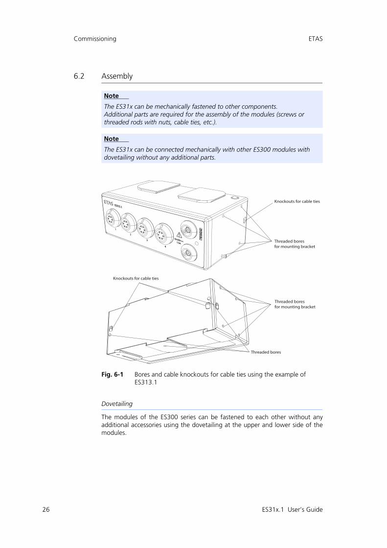
6.2 Assembly
Fig. 6-1 Bores and cable knockouts for cable ties using the example of ES313.1
Dovetailing
The modules of the ES300 series can be fastened to each other without anyadditional accessories using the dovetailing at the upper and lower side of themodules.
Note
The ES31x can be mechanically fastened to other components.Additional parts are required for the assembly of the modules (screws or threaded rods with nuts, cable ties, etc.).
Note
The ES31x can be connected mechanically with other ES300 modules with dovetailing without any additional parts.
Knockouts for cable ties
Threaded boresfor mounting bracket
Knockouts for cable ties
Threaded boresfor mounting bracket
Threaded bores
ES31x.1 User’s Guide

ETAS Commissioning
Assembly with mounting bracket
Fig. 6-2 Mounting bracket using the example of ES313.1
The ES313.1 features 4 bores each for fastening the mounting bracket withscrews on the side. It also features bores for fastening the module with screws onthe underside as well as on the rear side.
Knockouts for cable ties
Both sides of the ES313.1 feature 1 knockout each to the rear side of the modulefor fastening to other components using cable ties.
ES31x.1 User’s Guide 27

28
Commissioning ETAS
6.3 Applications
The modules of the ES300 series can be used individually or as part of a daisy-chain module chain for measuring and calibrating with INCA:
Fig. 6-3 ES300 modules and additional ETAS modules for MC applications
The daisy-chain concept enables a simple network architecture since only theES31x or the first module of the module chain must be connected with the businterface module.
6.4 Cabling
The order of the cabling of the connections is random. There are no special con-necting cables that can be ordered separately. An overview is located in the chap-ter 9 on page 48.
6.4.1 Sensors
A measuring cable is required to connect the sensors with the ES31x (see chapter9 on page 48)
Cabling the ES313.1 with the sensors
1. Connect the sensors and transducers with the con-nectors of the ES31x.
2. Record the assignment of the sensors to the inputs of the ES31x for your application program accord-ing to the cabling of the measuring setup.
ES313 ES321 ES322
4 8 16
Temperature TemperatureVoltage,Sensor Supply
ES59xES891
ES581.4
USBEthernet
CAN CANCAN
ES341
4
Counter and Frequency,Sensor Supply
CANCAN
ES314
8
Voltage,Sensor Supply
ES31x.1 User’s Guide

ETAS Commissioning
6.4.2 Daisy-Chain Connections
The cabling is carried out from the first module in the direction of the end of themodule chain.
Cabling the first module with the subsequent module
1. Connect a CAN connecting cable with one of the two connectors of the first module.
2. Connect the CAN connecting cable with the con-nector of the subsequent module.
3. Connect additional modules as described above.
Cabling the first module with the PC and the power supply
1. Connect the CAN connecting cable with the open second connector.
2. Connect the other end of the CAN connecting cable with the bus interface module.
3. Connect the voltage supply plug connectors of the CAN connecting cable with the desired power sup-ply.
Observe the color coding of the plug connectors.
Cabling the module chain with additional current feed
An additional current feed is required at the latest when a module is no longersupplied with sufficient current from the connected modules. This is indicated bythe fact that the status LEDs of the affected modules remain off despite a com-plete cabling.
1. Separate the module chain after the last module whose power supply is still ensured in the entire operating range.
2. Connect the CAN connecting cable with the con-nector of the ES31x of the last module of the chain in the direction of the PC.
3. Connect the CAN connecting cable with the con-nector of the module that is next in the direction of the cable end.
4. Connect the voltage supply plug connectors of the CAN connecting cable with the desired power sup-ply.
Observe the color coding of the plug connectors.
ES31x.1 User’s Guide 29

30
Software Description ETAS
7 Software Description
This chapter contains information about the following topics:
• „Description“ on page 30
• „System Requirements“ on page 30
• „IPEaddon in INCA“ on page 30
• „Functions“ on page 31
7.1 Description
The modules in the ES300 range can be configured using the IPEAddon for INCA.
7.2 System Requirements
You need software in the following versions to configure the ES3xx, as well as forcontrol and data acquisition:
• INCA 7.1 and higher
• IPEaddon INCA7.1.5 and higher
7.3 IPEaddon in INCA
To configure ES300 modules, they must either be added to a workspace inadvance or be able to be detected by the IPEaddon.
Note
The non-exclusive mode at the CAN bus is not supported.
Note
Operating the ES31x with older software versions is not possible.
Note
Please refer to the INCA User's Guide for information on how to add modules to a hardware environment.
ES31x.1 User’s Guide

ETAS Software Description
Opening IPEaddon
1. Select the node with the connected ES300 modules in the workspace.
or
Select one of the ES300 modules.
2. Click on Configure in the lower right-hand section of the screen.
Fig. 7-1 Opening IPEaddon
The IPETRONIK/ETAS window appears.
7.4 Functions
7.4.1 CAN Bus Configuration
In the hardware options, you can revise the synchronization mode and adjust thefilter settings.
Note
When the IPEaddon is open, other INCA windows cannot be used.
Note
The CAN bus of the ES3xx modules supports a fixed baud rate of 500 kBd. A module cannot be detected with a different baud rate. It is also not possible to change the baud rate.
ES31x.1 User’s Guide 31

32
Software Description ETAS
Synchronization mode
You can choose between the Free-running and synchronous modes.
In Free-running mode, only the channels of the respective modules are synchro-nized by an internal master clock.
In synchronous mode, the modules are synchronized with one another (seechapter 5.2.4 on page 22).
Configuring the synchronization mode
1. Select Hardware Options in the menu bar.
The IPETRONIK / ETAS: Options window appears.
2. Select the CAN interfaces tab.
3. In the CAN device synchronization mode section select one of the two Free-running or synchro-nous modes.
4. Click on OK.
Fig. 7-2 Synchronization mode of the CAN devices
7.4.2 Initialization
Detecting modules
INCA checks which modules are connected to your computer. The configurationon the PC is overwritten by the configuration of the modules.
Detecting modules
1. Select Hardware Detect in the menu bar.
Hardware detection starts.
Once the detection process is complete, all detected modules are displayed in the left-hand section of the window.
ES31x.1 User’s Guide

ETAS Software Description
Initializing modules
The configuration of the modules is overwritten by the current configuration onthe PC.
Initializing modules
1. Select Hardware Initialize in the menu bar.
The hardware initialization process starts.
Once the initialization process is complete, the respective status of the modules is displayed with a symbol.
Resetting modules
The configuration on the PC is reset to the last status.
Resetting modules
1. Select Hardware Reset in the menu bar.
The reset process starts.
Once the reset process has been completed, the last values detected by the modules are displayed.
Standard values for the initialization process
The configuration of the modules is overwritten with the respective standardconfiguration.
Initializing standard values
1. Select Hardware Default init in the menu bar.
The initialization of the standard values starts.
Once the initialization process is complete, the modules are reset to the default values.
Note
The symbol signalizes that the module could not be initialized. In this case, check whether the module has been correctly connected.
ES31x.1 User’s Guide 33

34
Software Description ETAS
7.4.3 Setting Up Aliasing Filters
You can find more information about the filters in chapter 5.1.1 on page 19
Setting up aliasing filters
1. Select Hardware Options in the menu bar.
The IPETRONIK / ETAS: Options window appears.
2. Select the Options tab.
3. Activate/deactivate the option Aliasing-free filter settings.
Fig. 7-3 Setting up aliasing filters
4. Click on OK.
7.4.4 Configuring ES300 Modules
On the left-hand side of the window, you can find the nodes and the modulesyou added to the workspace. In the standard view, you can see the name anddevice type of each module. You can also add further columns in this view, suchas the bus load.
Note
Avoid a bus load of more than 100%. If the bus load is above 100%, not all signals are displayed in the INCA experiment. The experiment cannot be per-formed and is aborted. To reduce the bus load- deactivate individual channels or - reduce the acquisition rate of individual modules.
Note
Deactivated signals are not displayed in the INCA experiment.
ES31x.1 User’s Guide

ETAS Software Description
The following columns are also recommended:
Adding columns
1. Right-click on the header.
A context menu appears.
Fig. 7-4 Module configuration context menu
2. Select the Column Chooser entry.
The Customization window appears with the selection of all available columns.
Fig. 7-5 Module configuration column selection
3. Select one or more columns by double-clicking on them.
Column Description
Bus load Utilization of the CAN bus
CAN send rate Send speed of the CAN bus
Date of last calibration Date on which the module was last calibrated
Device production date Manufacture date of the module
Download kernel version Download kernel version
Firmware version Firmware version
FPGA version FPGA version
Hardware Version Hardware Version
Configuration version Configuration version
License Info Information on the license
PIC firmware version PIC firmware version
Clock Synchronization mode
ES31x.1 User’s Guide 35

36
Software Description ETAS
7.4.5 Configuring a Channel
Adding columns
1. Right-click on the header.
A context menu appears.
Fig. 7-6 Channel configuration context menu
2. Select the Column Chooser entry.
The Customization window appears with the selection of all available columns.
Fig. 7-7 Module configuration column selection
3. Select one or more columns by double-clicking on them.
ES31x.1 User’s Guide

ETAS Software Description
Changing a value in a cell
1. Click in the cell containing the value you want to change.
You can change the value manually or select a value from a drop-down list depending on the cell type.
2. Select the value from the drop-down list.
or
Change the value manually.
You can adjust the following parameters:
7.4.6 Adjustment
Offset adjustment
You can use the offset adjustment to set up measuring devices to eliminateknown systematic deviations for the intended application. In contrast to calibra-tion, changes to the offset adjustment are permanent.
Adjusting the offset
3. Select Adjust Offset adjustment in the menu bar.
The Offset adjust window appears.
4. Group one or more channels by assigning groups to the respective channels in the Group column.
5. Adjust the reference value for the channel(s) by changing the value in the Reference value col-umn.
6. Adjust the offset value for the channel(s) by chang-ing the value in the Offset value column.
7. Under Selection, select the group you wish to adjust.
Column Description
Sensor mode Operating mode of the measurement input (volt-age/current including sensor supply)
Sensor max Upper limit of the specified measuring range
Sensor min Lower limit of the specified measuring range
Phys high Upper scaling point of the physical area (Y2)
Phys low Lower scaling point of the physical area (Y1)
Sensor supply Specified sensor supply voltage
Hardware filter Activation of the hardware filter test!
Averaging Moving average for smoothing unwanted signal jumps and noise components
ES31x.1 User’s Guide 37

38
Software Description ETAS
8. Click on Start.
The Adjust channels temporary window appears.
In the Result column, you can see whether the adjustment has been successful.
Fig. 7-8 Offset adjustment
7.4.7 Import / Export Module Configuration
Import
You can import the configurations from a CSV file.
Importing a configuration
1. Select Configure Import CSV import in the menu bar.
An Explorer window appears.
2. Select the CSV file you want to import.
3. Click on Open.
The Import - CSV import window appears.
If the window disappears without any further mes-sages, the CSV import was successful.
ES31x.1 User’s Guide

ETAS Software Description
Export
You can export the configuration in the following file formats:
• CANdb export
• XML CANdb export
• CSV export
Exporting a configuration
1. Select Configure Export CANdb export in the menu bar
or
XML CANdb export
or
CSV export.
An Explorer window appears.
2. Select the storage location for the file.
3. Enter a filename.
4. Click on Save.
The configuration was successfully exported.
ES31x.1 User’s Guide 39

40
Technical Data ETAS
8 Technical Data
This chapter contains information about the following topics:
• "General Data" on page 40
• "RoHS Conformity" on page 42
• "CE Marking" on page 42
• "Product Return and Recycling" on page 42
• "Materials Subject to Declaration" on page 43
• "System Requirements" on page 43
• "Electrical Data" on page 44
• "Terminal Assignment" on page 46
8.1 General Data
8.1.1 Identifications on the Module
The following symbols are used for module labeling:
Symbol Description
The User's Guide must be read prior to the startup of the product!
SN: 12345678 Serial number (eight digits)
Vx.yz Hardware version of the module
F 00K 123 456 Order number of the product (see chapter 10 on page 52)
10-33 V Operating voltage
1.5 A ES313.1 Current consumption
2 A ES314.1 Current consumption
Risk of burning on hot surfaces of the module!Do not touch the surfaces of the module during operation at high ambient temperatures.The surface temperature of the module can reach 90 °C / 194 °F when it is used in a vehicle and at an ambient temperature of 70 °C / 158 °F.
Marking for CE conformity (see chapter 8.3 on page 42)
Marking for China RoHS (see chapter 8.2 on page 42)
Marking for WEEE (see chapter 8.4 on page 42)
ES31x.1 User’s Guide

ETAS Technical Data
8.1.2 Standards
The ES31x meets the following norms and standards:
8.1.3 Ambient Conditions
8.1.4 Maintenance of the Product
The product is maintenance-free.
Standard Test
EN 61326-1:2013 Electrical equipment for measurement, control andlaboratory use - EMC requirements
IEC 61010-1:2010 Safety requirements for electrical equipment
IEC 61010-2-030:2010 Safety requirements for electrical equipment
WARNING!
This is class A equipment. This equipment can cause radio interfer-ence in residential areas. In this case, the user may be required to take appropriate measures.
CAUTION!
The module is not suitable for use in direct current systems.
Operating temperature range -40 °C to +105 °C-40 °F to +221 °F
Storage temperature range -55 °C to +150 °C-67 °F to +302 °F
Operating altitude max. 3,000 m / 9,842 ft
Degree of protection IP67
CAUTION!
Loss of Properties After IP67!Do not open or change the module housing!Work on the module housing may only be performed by qualified personnel.
ES31x.1 User’s Guide 41

42
Technical Data ETAS
8.1.5 Cleaning the Product
Use a dry or lightly moistened, soft, lint-free cloth for cleaning the product hous-ing. Sprays, solvents or abrasive cleaners, which could damage the housing,should be avoided. Do not spray any cleaning agent directly onto the product forcleaning. It must be ensured that no moisture enters the housing.
8.1.6 Mechanical Data
8.2 RoHS Conformity
8.2.1 European Union
The EU Directive 2011/65/EU limits the use of certain dangerous materials forelectric and electronic devices (RoHS conformity).
ETAS confirms that the product meets this directive applicable in the EuropeanUnion.
8.2.2 China
With the China RoHS identification attached to the product or its packaging,ETAS confirms that the product meets the guidelines of the "China RoHS" (Man-agement Methods for Controlling Pollution Caused by Electronic InformationProducts Regulation) applicable in the People's Republic of China.
8.3 CE Marking
With the CE mark attached to the product or its packaging, ETAS confirms thatthe product corresponds to the product-specific, applicable European Directives.The CE Declaration of Conformity for the product is available upon request.
8.4 Product Return and Recycling
The European Union (EU) released the Directive for Waste Electrical and Elec-tronic Equipment - WEEE to ensure the setup of systems for collecting, treatingand recycling electronic waste in all countries of the EU.
This ensures that the devices are recycled in a resource-friendly way that does notrepresent any risk to personal health and the environment.
Fig. 8-1 WEEE symbol
Dimensions (H x W x D) ES313.1 43 x 106 x 60 mm
1.69 x 4.17 x 2.36 in
ES314.1 41 x 204 x 55 mm
1.61 x 8.03 x 2.17 in
Weight ES313.1 420 g / 0.93 lb
ES314.1 695 g / 1.53 lb
ES31x.1 User’s Guide

ETAS Technical Data
The WEEE symbol (see Fig. 8-1) on the product or its packaging identifies that theproduct may not be disposed of together with the remaining trash.
The user is obligated to separately collect old devices and provide them to theWEEE return system for recycling.
The WEEE Directive applies to all ETAS devices, but not to external cables or bat-teries.
Additional information about the recycling program of ETAS GmbH is availablefrom the ETAS sales and service locations (see chapter 11 on page 55).
8.5 Materials Subject to Declaration
European Union
Some products from ETAS GmbH (e.g. modules, boards, cables) use componentswith materials that are subject to declaration in accordance with the REACH reg-ulation (EC) no.1907/2006. Detailed information is located in the ETAS down-load center in the customer information "REACH Declaration" (www.etas.com/Reach). This information is continuously being updated.
8.6 System Requirements
8.6.1 Hardware
Power supply
Operating the modules requires a DC voltage supply of 10 V to 33 V DC.
Bus interface module
Operating the modules requires a bus interface module with which a connectionto the PC is established. The following bus interface modules can be used:
• ES523.1
• ES581.4
• ES592.1
• ES595.1
• ES891.1
8.6.2 Software
For the configuration of the ES31x as well as the control and data acquisition,you need software in the following versions:
• INCA 7.1 and higher
• IPEaddon INCA7.1.5 and higher
Note
Operating the ES31x with older software versions is not possible.
ES31x.1 User’s Guide 43

44
Technical Data ETAS
8.7 Electrical Data
8.7.1 Voltage Supply
8.7.2 Host Interface
8.7.3 Sensor Power Supply
Operating voltage 10 V to 33 V DC
Power consumption ES313.1 max. 1.5 A
ES314.1 max. 2 A
Connection LEMO
Bus CAN 2.0B
Data transmission (baud rate) 500 kBd
Measuring data in the CAN messageResolution (format)Sign
8 bit (byte) and 16 bit (word), select-ablesigned, unsigned
Sensor power supply channels 4, separate for each input channel
Output voltage Each channel can be set separately:“Off”, in increments (2.5 / 5 / 7.5 / 10 / 12.5 / 15 V)
Output current max. 60 mA
Protection Short circuit-proof, overcurrent safety switch-off, Switch-off time = 400 msSwitch-on time = 2000 ms
Diagnostics In case of overcurrent, -FS is returned as measured value
ES31x.1 User’s Guide

ETAS Technical Data
8.7.4 Sensor Inputs
Properties
Characteristics
Input Channel ES313.1: 4
ES314.1: 8
A/D converter 16 bit SAR converter
Hardware input filter Butterworth 8th order, 250 Hz cutoff frequency, switchable
Sampling rate application tool 1 Hz to 2 kHz per channel, configurable
Input voltage ranges 0.1 V to 60 V
Maximum input voltage Input to input:max. 60 VDC / 30 VAC (dry environ-ment)max. 35 VDC / 16 VAC (wet environ-ment)
Input to ground supply voltage or to housing:max. 60 VDC / 30 VAC (dry environ-ment)max. 35 VDC / 16 VAC (wet environ-ment)
Maximum input voltage resolution (16 bit)
Unipolar: 1.5 VBipolar: 3.0 V
Maximum measuring error Unipolar: 25 °C (77 °F) ambient tem-perature ±0.13 %Bipolar: 25 °C (77 °F) ambient tem-perature ±0.05 %
Max. voltage drift (temperature),Temperatures -40 °C to +85 °C
-40 °C to +85 °C (-40 °F to +185 °F), ±40 ppm/K
Max. voltage drift (temperature),Temperatures +85 °C to +120 °C
+85 °C to +105 °C (+185 °F to +221 °F), ±80 ppm/K+105 °C to +125 °C (+221 °F to +257 °F), ±120 ppm/K
Input impedance 10 M
ES31x.1 User’s Guide 45

46
Technical Data ETAS
8.7.5 Signal Processing
Properties
8.8 Terminal Assignment
8.8.1 LEMO CAN Bus
Fig. 8-2 Terminal assignment
Resolution 16 bit
Sample rate 1 Hz to 2 kHz per channel, configurable
Hardware input filter Filter type Butterworth 8th order, 250 Hz cutoff frequency, switchable
Software filter (DSP) OptionalCutoff frequency and filter type select-able
Pin Signal Description
1 Power + Supply voltage, positive
2 Power + Supply voltage, positive
3 SYNC + Synchronization, plus
4 SYNC - Synchronization, minus
5 CAN GND CAN , ground
6 Power GND Supply voltage, negative
7 Power GND Supply voltage, negative
8 CAN + CAN signal, plus
9 CAN - CAN signal, minus
ES31x.1 User’s Guide

ETAS Technical Data
8.8.2 LEMO Sensor
Fig. 8-3 Terminal assignment
Pin Signal Description
1 VIN + Voltage measurement input, plus
2 VIN - / IIN -Voltage measurement input, ground /Current measurement input, minus
3 IIN + Current measurement input, plus
4 VOUT + Sensor supply, plus
5 GND Sensor supply, ground
6 VOUT - Sensor supply, minus
ES31x.1 User’s Guide 47

48
Cables and Accessories ETAS
9 Cables and Accessories
This chapter contains information on the following topics:
• "Measurement Cables" on page 48
• "Combined CAN Connection and Power Supply Cable" on page 49
• "CAN Chain Connection Cable" on page 51
• "CAN Termination Resistor Plug" on page 51
• "Mounting Bracket" on page 51
9.1 Measurement Cables
Fig. 9-1 Cable CBAV350.1
Measurement cable with open wires for measurement instruments ES31x
Note
Only use ETAS cables at the interfaces of the module. Adhere to the maximum cable lengths!
Product Length Order Number
CBAV350.1-3 3 m F-00K-110-542
ES31x.1 User’s Guide

ETAS Cables and Accessories
9.2 Combined CAN Connection and Power Supply Cable
9.2.1 CBCP300.1
Fig. 9-2 Cable CBCP300.1
CAN connection and power supply cable for ES3xx modules with integrated ter-mination and power supply
9.2.2 CBCP3005.1
Fig. 9-3 Cable CBCP3005.1
CAN connection and power supply cable for ES3xx modules with integrated ter-mination and power supply and safety banana connector
Product Length Order Number
CBCP300.1-3 3 m F-00K-110-544
Product Length Order Number
CBCP3005.1-3 3 m F-00K-110-755
------max.32V
+
-
------max.32V
+
-
ES31x.1 User’s Guide 49

50
Cables and Accessories ETAS
9.2.3 CBCP301.1
Fig. 9-4 Cable CBCP301.1
CAN connection and power supply cable for ES3xx modules with integrated ter-mination and power supply
9.2.4 CBCP3015.1
Fig. 9-5 Cable CBCP3015.1
CAN connection and power supply cable for ES3xx modules with integrated ter-mination and power supply and safety banana connector
Product Length Order Number
CBCP301.1-3 3 m F-00K-110-545
Product Length Order Number
CBCP3015.1-3 3 m F-00K-110-756
+
-
------max.32V
+
-
------max.32V
ES31x.1 User’s Guide

ETAS Cables and Accessories
9.3 CAN Chain Connection Cable
Fig. 9-6 Cable CBCX300.1
CAN chain connection cable for ES3xx modules
9.4 CAN Termination Resistor Plug
Fig. 9-7 CAN Termination Resistor Plug
CAN termination resistor plug for ES3xx modules
9.5 Mounting Bracket
Fig. 9-8 Mounting bracket for ES3xx
Mounting bracket for ES3xx modules
Product Length Order Number
CBCX300.1-0m15 0,15 m F-00K-110-546
CBCX300.1-0m5 0,5 m F-00K-110-547
Product Order Number
ES3xx_CAN_TERM F-00K-110-548
Product Order Number
ES3xx_BRACKET F-00K-110-549
ES31x.1 User’s Guide 51

52
Ordering Information ETAS
10 Ordering Information
10.1 ES313.1
10.2 ES314.1
Order Name Short Name Order Number
ES313.1 A/D Module with Sensor Supply (4 CH)
ES313.1 F-00K-110-531
Package Contents
- ES313.1 A/D Module with Sensor Supply (4 CH)- CDROM ES3xx_CD (software for ES3xx and documentation)- List “Content of this Package”- ES3xx_Safety Advice- China-RoHS-leaflet_ES3xx_orange_cn- Calibration-Certification
Note
Cables are not part of the scope of supplies of the module and must be ordered separately (see chapter 10.3 on page 53).
Order Name Short Name Order Number
ES314.1 A/D Module with Sensor Supply (8 CH)
ES314.1 F-00K-110-901
Package Contents
- ES314.1 A/D Module with Sensor Supply (8 CH)- CDROM ES3xx_CD (software for ES3xx and documentation)- List “Content of this Package”- ES3xx_Safety Advice- China-RoHS-leaflet_ES3xx_orange_cn- Calibration-Certification
Note
Cables are not part of the scope of supplies of the module and must be ordered separately (see chapter 10.3 on page 53).
ES31x.1 User’s Guide

ETAS Ordering Information
10.3 Accessories
10.3.1 Cables
Measurement Cables
Combined CAN Connection and Power Supply Cable
CAN Chain Connection Cables
Order Name Short Name Order Number
Measurement Cable for ES31x, Lemo 1B (6mc) - open wires (6c), 3m
CBAV350.1-3 F-00K-110-542
Note
If you require customized cables, please contact your ETAS contact partner.
Order Name Short Name Order Number
CAN Connection and Power Supply Cable for ES3xx with integrated termination resis-tor, Lemo 0B – DSUB – Banana (9mc-9fc+2mc), 3 m
CBCP300.1-3 F-00K-110-544
CAN Connection and Power Supply Cable for ES3xx with integrated termination resis-tor, Lemo 0B – DSUB – Safety Banana (9mc-9fc+2mc), 3 m
CBCP3005.1-3 F-00K-110-755
CAN Connection and Power Supply Cable for ES3xx with integrated termination resis-tor, Lemo 0B – Lemo 1B FGC – Banana (9mc-8mc+2mc), 3 m
CBCP301.1-3 F-00K-110-545
CAN Connection and Power Supply Cable for ES3xx with integrated termination resis-tor, Lemo 0B – Lemo 1B FGC – Safety Ban-ana (9mc-8mc+2mc), 3 m
CBCP3015.1-3 F-00K-110-756
Order Name Short Name Order Number
CAN chain connection cable for ES3xx, 0.15 m
CBCX300.1-0m15 F-00K-110-546
CAN chain connection cable for ES3xx, 0.50 m
CBCX300.1-0m5 F-00K-110-547
ES31x.1 User’s Guide 53

54
Ordering Information ETAS
10.3.2 Can Termination Resistor Plug
10.3.3 Mounting Bracket
10.3.4 Calibration Service
Order Name Short Name Order Number
CAN termination resistor plug for ES3xx ES3xx_CAN_TERM F-00K-110-548
Order Name Short Name Order Number
Mounting bracket for ES3xx modules (ES31x, ES341)
ES3xx_BRACKET F-00K-110-549
Bestellname Kurzname Bestellnummer
Calibration service for ES313 K_ES313 F-00K-110-539
Calibration service for ES314 K_ES314 F-00K-110-905
ES31x.1 User’s Guide

ES31x.1 User’s Guide 55
ETAS ETAS Contact Addresses
11 ETAS Contact Addresses
ETAS HQ
ETAS GmbH
ETAS Subsidiaries and Technical Support
For details of your local sales office as well as your local technical support teamand product hotlines, take a look at the ETAS website:
Borsigstraße 24 Phone: +49 711 3423-0
70469 Stuttgart Fax: +49 711 3423-2106
Germany WWW: www.etas.com
ETAS subsidiaries WWW: www.etas.com/en/contact.php
ETAS technical support WWW: www.etas.com/en/hotlines.php

ETAS Figures
Figures
Fig. 4-1 Housing ES313.1 (above) and ES314.1 (below) ........................................... 15Fig. 4-2 Connections ES313.1 (above) and ES314.1 (below)..................................... 17Fig. 5-1 Structure of a message according to CAN 2.0 B.......................................... 20Fig. 6-1 Bores and cable knockouts for cable ties using the example of ES313.1 ...... 26Fig. 6-2 Mounting bracket using the example of ES313.1 ........................................ 27Fig. 6-3 ES300 modules and additional ETAS modules for MC applications.............. 28Fig. 7-1 Opening IPEaddon ...................................................................................... 31Fig. 7-2 Synchronization mode of the CAN devices.................................................. 32Fig. 7-3 Setting up aliasing filters............................................................................. 34Fig. 7-4 Module configuration context menu........................................................... 35Fig. 7-5 Module configuration column selection ...................................................... 35Fig. 7-6 Channel configuration context menu.......................................................... 36Fig. 7-7 Module configuration column selection ...................................................... 36Fig. 7-8 Offset adjustment....................................................................................... 38Fig. 8-1 WEEE symbol.............................................................................................. 42Fig. 8-2 Terminal assignment................................................................................... 46Fig. 8-3 Terminal assignment................................................................................... 47Fig. 9-1 Cable CBAV350.1....................................................................................... 48Fig. 9-2 Cable CBCP300.1 ....................................................................................... 49Fig. 9-3 Cable CBCP3005.1 ..................................................................................... 49Fig. 9-4 Cable CBCP301.1 ....................................................................................... 50Fig. 9-5 Cable CBCP3015.1 ..................................................................................... 50Fig. 9-6 Cable CBCX300.1....................................................................................... 51Fig. 9-7 CAN Termination Resistor Plug ................................................................... 51Fig. 9-8 Mounting bracket for ES3xx........................................................................ 51ES31x.1 User’s Guide 56

ETAS Index
Index
AA/D converter 19Accident prevention 8Aliasing effects 19Aliasing filters 34Ambient conditions 41Applications 28BBores with thread 26Bores with thread for mounting bra-
cket 26
CCable ties 26Cabling 28
Daisy chain 29Sensors 28
Cabling concept 13Calibration 24CE Declaration of Conformity 42Channel configurations 36Cleaning the product 42Commissioning 25Configuration 23Configuring ES300 modules 34Connection
LEMO CAN bus 46LEMO sensor 47
Connections 17
DDaisy-chain connections 17Daisy-chain topology 13Data
electrical 44mechanical 42
Data transmission 20Decentral cabling concept 13Documentation 8
EElectrical data 44Electrical isolation 19Electrical safety 9ETAS Contact Addresses 55Export module configuration 38
FFilter 19, 45Firmware update 23
HHost interface 44Housing 16HSP 23
IIdentifications on the module 40Impedance 45Import module configuration 38
ES31x.1 User’s Guide 57
58
Index ETAS
Initialization 32Input filter 45Input impedance 45Input voltage ranges 45Input voltage resolution 45Input voltage, maximum 45IPEaddon 30
KKnockouts for cable ties 26
LLEDs 18
MMeasure-Error 45Mechanical data 42Mounting bracket 27
OOffset adjustment 37Operation
Conventions 7Use Case 7
Overvoltage protection 19
PPotential differences 22Power supply 44Presentation of information 7Product
Exclusion of liability 8Product return 42
QQualification, required 8
RREACH regulation 43Recycling 42Resolution 44, 46RoHS conformity
China 42European Union 42
SSafety at work 8Safety notices
basic 8Identification 6
Safety precautions 8Sample rate 46
Scope of supply 7Sensor power supply 44Sensor supply 20Signal processing 19Software description 30Standards 41Supply Voltage 44Synchronization 22Synchronization mode 32
Clock synchronized 32Free running 32
System requirements 43Hardware 43Software 43
TTechnical Data 40Terminal assignment 46Tool integration 23
UUse, intended 8
VVoltage drift 45Voltage supply 44
WWEEE return system 42
YY boost cable 22
ES31x.1 User’s Guide