Embed Size (px)
Citation preview
Paperless Recorderfor secure acquisition
of FDA-compliantmeasurement data
B 70.6560.4Installation Instructions
11.07/00415650
es
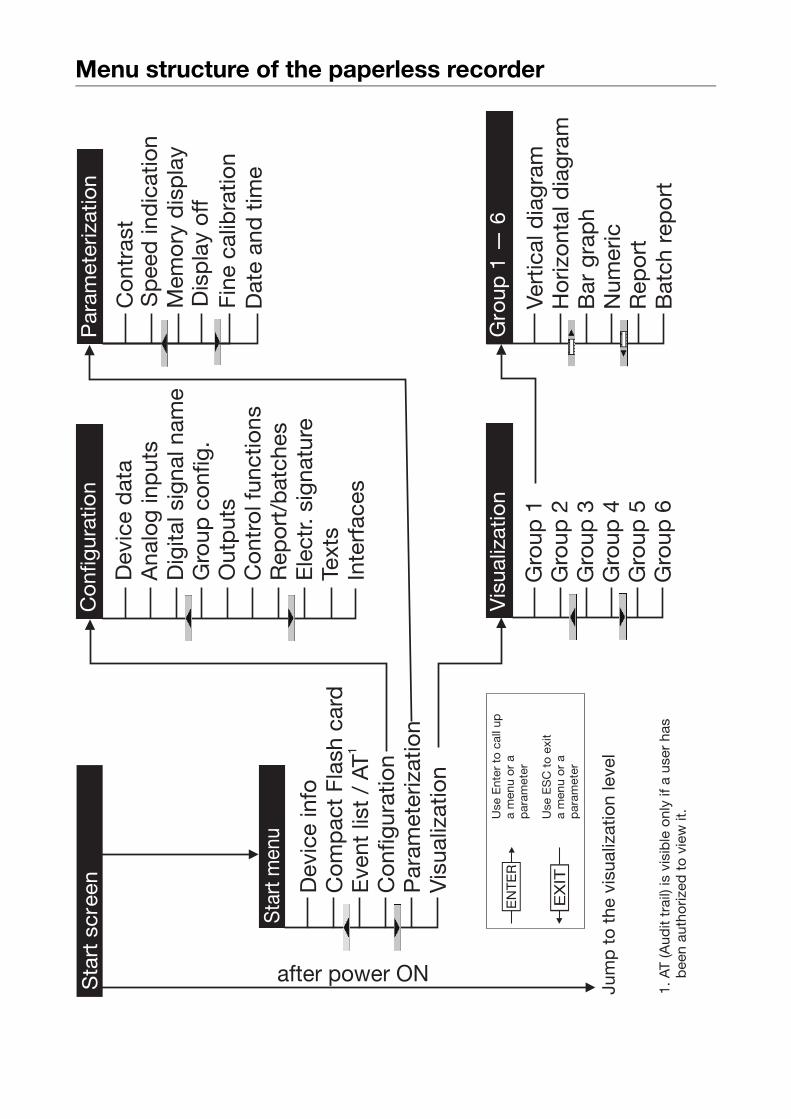
Menu structure of the paperless recorder
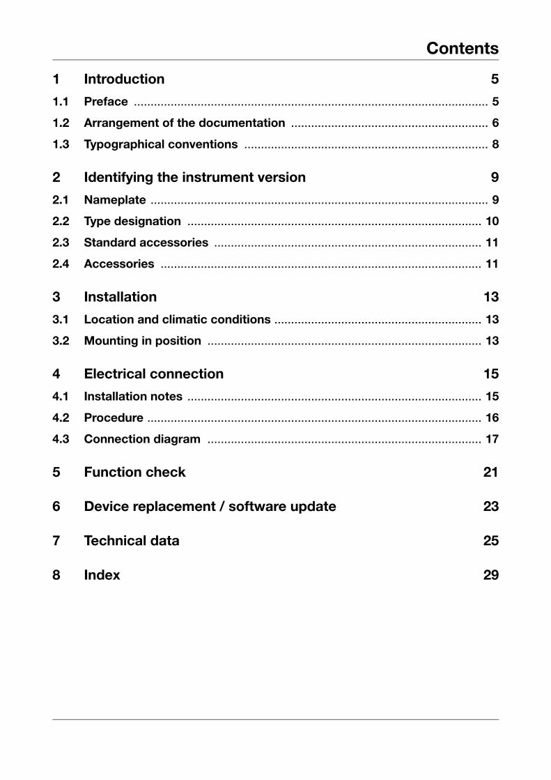
Contents
1 Introduction 5
1.1 Preface .......................................................................................................... 5
1.2 Arrangement of the documentation ........................................................... 6
1.3 Typographical conventions ......................................................................... 8
2 Identifying the instrument version 9
2.1 Nameplate ..................................................................................................... 9
2.2 Type designation ........................................................................................ 10
2.3 Standard accessories ................................................................................ 11
2.4 Accessories ................................................................................................ 11
3 Installation 13
3.1 Location and climatic conditions .............................................................. 13
3.2 Mounting in position .................................................................................. 13
4 Electrical connection 15
4.1 Installation notes ........................................................................................ 15
4.2 Procedure .................................................................................................... 16
4.3 Connection diagram .................................................................................. 17
5 Function check 21
6 Device replacement / software update 23
7 Technical data 25
8 Index 29

Contents
1 Introduction
1.1 PrefacePlease read these Installation Instructions before commissioning the instru-ment. Keep the instructions in a place that is accessible to all users at alltimes.
Please assist us to improve these installation instructions, where necessary.
Your suggestions will be appreciated.
HIf any problems should occur during commissioning, please do notcarry out any manipulations on the unit, as this could endangeryour rights under the instrument warranty!
Please contact the nearest subsidiary or the head office in such acase.
E
When returning modules, assemblies and components, the regula-tions of EN 61340-5-1 and EN 61340-5-2 “Protection of electronicdevices from electrostatic phenomena” must be observed. Useonly the appropriate ESD packaging for transport.
Please note that we cannot accept any liability for damage causedby ESD (electrostatic discharge).
B
5
1 Introduction
1.2 Arrangement of the documentationThe documentation for this instrument is addressed to the equipment manu-facturer (OEM) and users with appropriate technical expertise. It consists ofthe following parts:
Sales documentation in PDF file format
White Paper The White Paper presents the company’s position with regard to the legislation“21 CFR Part 11” of the American health authority FDA (Food and Drug Ad-ministration). With each section of the regulatory text, the user is given infor-mation on the fulfillment of the requirements.
Productdescription
The product description illustrates the safety and operating concepts behindthe system, and the results that can be achieved by JUMO in the course of thevalidation of an installation. It is intended to serve as an introduction to thesystem, and not as a formal technical documentation.
Instrument documentation in printed form
B 70.6560.1 Operating Instructions
The operating instructions are an extract from the operating manual. They co-ver the basic operation of the paperless recorder.
B 70.6560.4 Installation Instructions
The installation instructions describe the installation of the paperless recorderand the connection of the supply and signal cables. The instructions also con-tain a list of the technical data.
Instrument documentation in PDF file format
The “Instrument documentation in PDF file format” is on the CD that is inclu-ded in the delivery.
B 70.6560.0 Operating Manual
It contains information about commissioning, operation and parameter settingon the instrument as well as through the PC setup program (option).
B 70.6560.1 Operating Instructions
The operating instructions are an extract from the operating manual. They co-ver the basic operation of the paperless recorder.
6
1 Introduction
B 70.6560.2.0 Interface description (serial interfaces)
This provides information on the communication (RS232; RS422/RS485) withsupervisory systems.
Interface description (Ethernet interface)
This provides information on the connection of a paperless recorder to a com-pany-internal network. The description is incorporated in the B 70.6560.2.0
B 70.6560.2.1 Interface description (LON interface)
This provides information on the connection and use of modules of the “JUMOmTRON automation system”.
B 70.6560.2.3 Interface description (PROFIBUS-DP interface)
This provides information on the connection of a paperless recorder to aPROFIBUS-DP system.
B 70.6560.4 Installation instructions
The installation instructions describe the installation of the paperless recorderand the connection of the supply and signal cables. They also contain a list ofthe technical data.
T 70.6560 Data sheet
The data sheet contains general information, the order details and the techni-cal data.
H All documents are available on the Internet for downloading atwww.jumo.net
7
1 Introduction
1.3 Typographical conventions
Warning signs
The signs for Danger and Caution are used in this manual under the followingconditions:
V
Danger
This symbol is used where there may be danger to personnel if the instruc-tions are disregarded or not followed accurately!
A
Caution
This symbol is used where there may be damage to equipment or data if theinstructions are disregarded or not followed accurately!
E
Caution
This symbol is used where special precautions must be taken when handlingelectrostatically sensitive components.
Note signs
H
Note
This symbol is used to draw your special attention to a remark.
v
Reference
This sign refers to further information in other manuals, chapters or sections.
abc1Footnote
Footnotes are comments that refer to specific parts of the text. Footnotesconsist of two parts: a marking in the text and the footnote text.
The marking in the text is arranged as continuous superscript numbers.
h
Action
This sign marks the description of a required action.
The individual steps are indicated by this asterisk, e. g.
h Press the h key
h Confirm with E
8
2 Identifying the instrument version
2.1 Nameplate
Identification
Position The nameplate is affixed to the paperless recorder.
Contents It contains important information such as:
Typ Please compare the type that was supplied with your order details. You canidentify the type by referring to Chapter 2.2 “Type designation”.
VARTN The sales number unambiguously designates the article in the catalog. It isused for communication between the customer and the sales department.
F-Nr The production number indicates the production date (year/week). The figuresconcerned are in position 12, 13, 14, 15.
Example:
F-Nr 0022969000003130006
This shows that the paperless recorder was manufactured in 2003, week 13.
Repeat order for a recorder in the identical version
When placing a repeat order for a paperless recorder of the same type, it is ne-cessary to state “Typ”, “VARTN” and “F-Nr.” This is the only way an instrumentof the same type can be produced.
Description Designation onnameplate
Example
Instrument type Typ 706560/10-888,000-51-0032-0032-23,020
Sales number VARTN 70/00342163Production number F-Nr 0022969000003130006Supply voltage AC 110 … 240V
+10/-15%, 48…63Hz
9
2 Identifying the instrument version
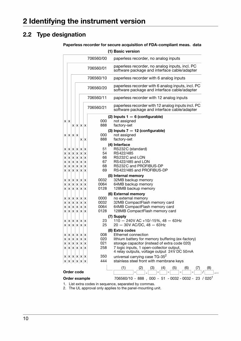
2.2 Type designation
Paperless recorder for secure acquisition of FDA-compliant meas. data
(1) Basic version
706560/00 paperless recorder, no analog inputs
706560/01 paperless recorder, no analog inputs, incl. PC software package and interface cable/adapter
706560/10 paperless recorder with 6 analog inputs
706560/20 paperless recorder with 6 analog inputs, incl. PC software package and interface cable/adapter
706560/11 paperless recorder with 12 analog inputs
706560/21 paperless recorder with 12 analog inputs incl. PC software package and interface cable/adapter
(2) Inputs 1 — 6 (configurable)x x 000 not assigned
x x x x 888 factory-set(3) Inputs 7 — 12 (configurable)
x x x x 000 not assignedx x 888 factory-set
(4) Interfacex x x x x x 51 RS232C (standard)x x x x x x 54 RS422/485x x x x x x 66 RS232C and LONx x x x x x 67 RS422/485 and LONx x x x x x 68 RS232C and PROFIBUS-DPx x x x x x 69 RS422/485 and PROFIBUS-DP
(5) Internal memoryx x x x x x 0032 32MB backup memoryx x x x x x 0064 64MB backup memoryx x x x x x 0128 128MB backup memory
(6) External memoryx x x x x x 0000 no external memoryx x x x x x 0032 32MB CompactFlash memory cardx x x x x x 0064 64MB CompactFlash memory cardx x x x x x 0128 128MB CompactFlash memory card
(7) Supplyx x x x x x 23 110 — 240V AC +10/-15%, 48 — 63Hzx x x x x x 25 20 — 30V AC/DC, 48 — 63Hz
(8) Extra codesx x x x x x 008 Ethernet connectionx x x x x x 020 lithium battery for memory buffering (ex-factory)x x x x x x 021 storage capacitor (instead of extra code 020)x x x x x x 258 7 logic inputs, 1 open-collector output,
4 relay outputs, voltage output 24V DC 50mAx x x x x x 350 universal carrying case TG-352
x x x x x x 444 stainless steel front with membrane keys
(1) (2) (3) (4) (5) (6) (7) (8)Order code - , - - - - / ,...
Order example 706560/10 - 888 , 000 - 51 - 0032 - 0032 - 23 / 0201
1. List extra codes in sequence, separated by commas.2. The UL approval only applies to the panel-mounting unit.
10
2 Identifying the instrument version
2.3 Standard accessories- 1 Installation Instructions B 70.6560.4
- 1 Operating Instructions B 70.6560.1
- 2 mounting brackets
- 4 cable-tie with foot (can be released) for strain relief of the sensor connection cables
- 1 CD with additional documentation(see Chapter 1.2 “Arrangement of the documentation”)
2.4 Accessories- PC software package consisting of:
setup program,
PC evaluation software (PCA3000),
PCA communications software (PCC),
PC Security Manager software (PCS) and
PC Audit Trail Manager software (PCAT).
- PC interface cable with TTL/RS232 converter and adapter, for setup program, Sales No. 70/00350260
- PC interface cable with USB/TTL converter, adapter (socket) and adapter (pins) for setup program, Sales No. 70/00456352
11
2 Identifying the instrument version
12
3 Installation
3.1 Location and climatic conditionsThe location should be as free as possible from shock and vibration. Strayelectromagnetic fields from motors, transformers etc. should be avoided.
The ambient temperature at the location can be 0 to +45°C, at a relative hu-midity of ≤75%, no condensation.
v Chapter 4.1 “Installation notes”
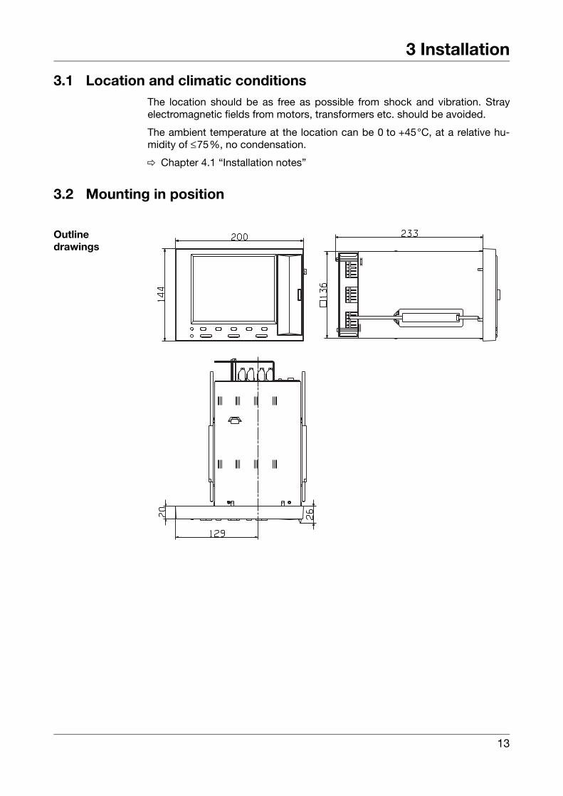
3.2 Mounting in position
Outlinedrawings
13
3 Installation
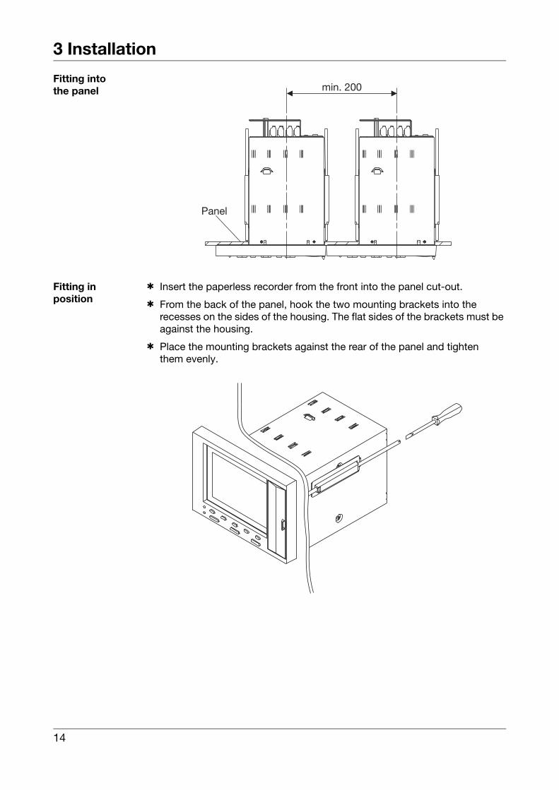
Fitting intothe panel
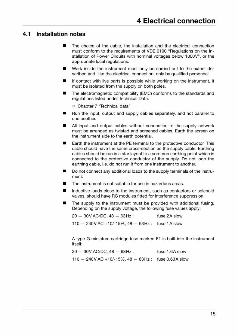
Fitting inposition
h Insert the paperless recorder from the front into the panel cut-out.
h From the back of the panel, hook the two mounting brackets into therecesses on the sides of the housing. The flat sides of the brackets must be against the housing.
h Place the mounting brackets against the rear of the panel and tightenthem evenly.
Panel
min. 200
14
4 Electrical connection
4.1 Installation notes
k The choice of the cable, the installation and the electrical connectionmust conform to the requirements of VDE 0100 “Regulations on the In-stallation of Power Circuits with nominal voltages below 1000V”, or theappropriate local regulations.
k Work inside the instrument must only be carried out to the extent de-scribed and, like the electrical connection, only by qualified personnel.
k If contact with live parts is possible while working on the instrument, itmust be isolated from the supply on both poles.
k The electromagnetic compatibility (EMC) conforms to the standards andregulations listed under Technical Data.
v Chapter 7 “Technical data”
k Run the input, output and supply cables separately, and not parallel toone another.
k All input and output cables without connection to the supply networkmust be arranged as twisted and screened cables. Earth the screen onthe instrument side to the earth potential.
k Earth the instrument at the PE terminal to the protective conductor. Thiscable should have the same cross-section as the supply cable. Earthingcables should be run in a star layout to a common earthing point which isconnected to the protective conductor of the supply. Do not loop theearthing cable, i.e. do not run it from one instrument to another.
k Do not connect any additional loads to the supply terminals of the instru-ment.
k The instrument is not suitable for use in hazardous areas.
k Inductive loads close to the instrument, such as contactors or solenoidvalves, should have RC modules fitted for interference suppression.
k The supply to the instrument must be provided with additional fusing.Depending on the supply voltage, the following fuse values apply:
20 — 30V AC/DC, 48 — 63Hz : fuse 2A slow
110 — 240V AC +10/-15%, 48 — 63Hz : fuse 1A slow
A type-G miniature cartridge fuse marked F1 is built into the instrumentitself:
20 — 30V AC/DC, 48 — 63Hz : fuse 1.6A slow
110 — 240V AC +10/-15%, 48 — 63Hz : fuse 0.63A slow
15
4 Electrical connection
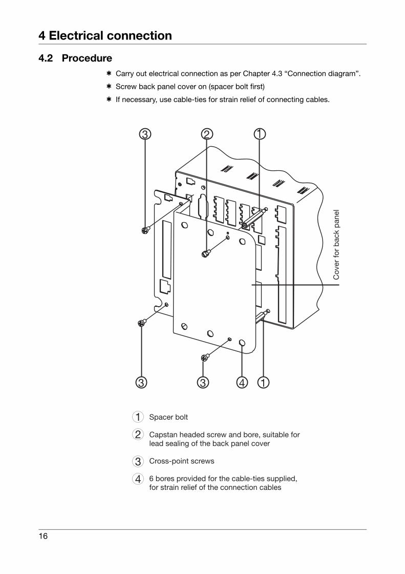
4.2 Procedureh Carry out electrical connection as per Chapter 4.3 “Connection diagram”.
h Screw back panel cover on (spacer bolt first)
h If necessary, use cable-ties for strain relief of connecting cables.
16
4 Electrical connection
4.3 Connection diagram
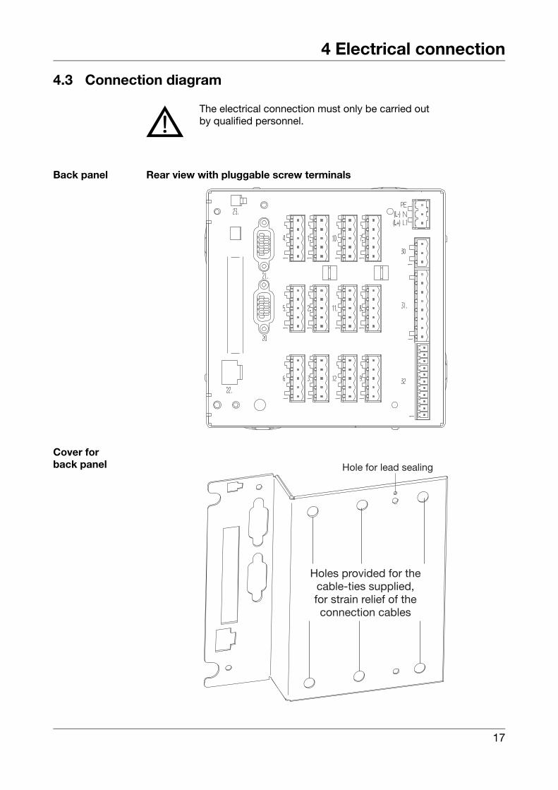
Back panel Rear view with pluggable screw terminals
Cover forback panel
V
The electrical connection must only be carried outby qualified personnel.
(L-)(L+)
Hole for lead sealing
Holes provided for thecable-ties supplied,for strain relief of theconnection cables
17
4 Electrical connection
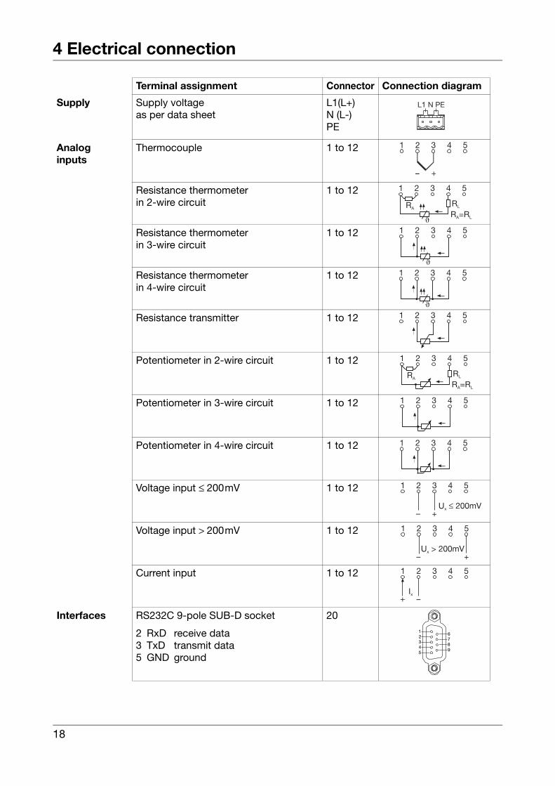
Terminal assignment Connector Connection diagram
Supply Supply voltageas per data sheet
L1(L+)N (L-)PE
Analoginputs
Thermocouple 1 to 12
Resistance thermometerin 2-wire circuit
1 to 12
Resistance thermometerin 3-wire circuit
1 to 12
Resistance thermometerin 4-wire circuit
1 to 12
Resistance transmitter 1 to 12
Potentiometer in 2-wire circuit 1 to 12
Potentiometer in 3-wire circuit 1 to 12
Potentiometer in 4-wire circuit 1 to 12
Voltage input ≤ 200mV 1 to 12
Voltage input > 200mV 1 to 12
Current input 1 to 12
Interfaces RS232C 9-pole SUB-D socket
2 RxD receive data3 TxD transmit data5 GND ground
20
RLRA
R =RA L
21 3 4 5
�
21 3 4 5
�
21 3 4 5
�
RLRA
R =RA L
21 3 4 5
21 3 4 5
21 3 4 5
21
345
6789
18
4 Electrical connection
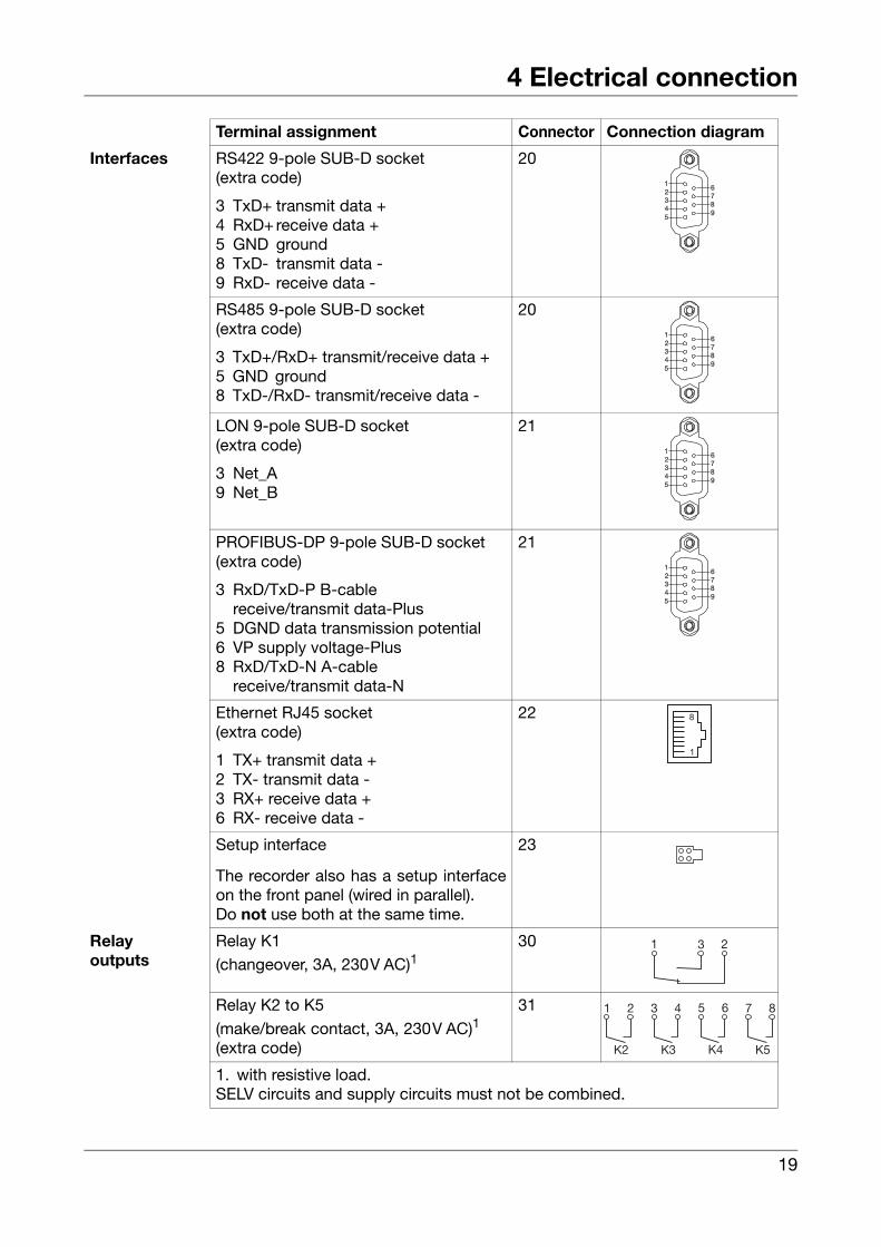
Interfaces RS422 9-pole SUB-D socket(extra code)
3 TxD+ transmit data +4 RxD+ receive data +5 GND ground8 TxD- transmit data -9 RxD- receive data -
20
RS485 9-pole SUB-D socket(extra code)
3 TxD+/RxD+ transmit/receive data +5 GND ground8 TxD-/RxD- transmit/receive data -
20
LON 9-pole SUB-D socket(extra code)
3 Net_A9 Net_B
21
PROFIBUS-DP 9-pole SUB-D socket(extra code)
3 RxD/TxD-P B-cablereceive/transmit data-Plus
5 DGND data transmission potential6 VP supply voltage-Plus8 RxD/TxD-N A-cable
receive/transmit data-N
21
Ethernet RJ45 socket(extra code)
1 TX+ transmit data +2 TX- transmit data -3 RX+ receive data +6 RX- receive data -
22
Setup interface
The recorder also has a setup interfaceon the front panel (wired in parallel).Do not use both at the same time.
23
Relayoutputs
Relay K1 (changeover, 3A, 230V AC)1
30
Relay K2 to K5 (make/break contact, 3A, 230V AC)1
(extra code)
31
1. with resistive load.SELV circuits and supply circuits must not be combined.
Terminal assignment Connector Connection diagram
21
345
6789
21
345
6789
21
345
6789
21
345
6789
8
1
21 3
21
K2
43
K3
65
K4
87
K5
19
4 Electrical connection
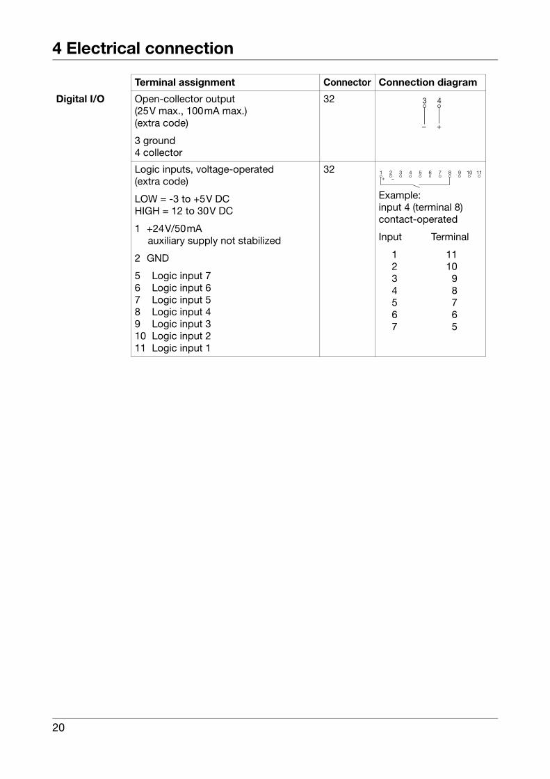
Digital I/O Open-collector output(25V max., 100mA max.)(extra code)
3 ground4 collector
32
Logic inputs, voltage-operated(extra code)
LOW = -3 to +5V DCHIGH = 12 to 30V DC
1 +24V/50mA auxiliary supply not stabilized
2 GND
5 Logic input 76 Logic input 67 Logic input 58 Logic input 49 Logic input 310 Logic input 211 Logic input 1
32
Example: input 4 (terminal 8)contact-operated
Input Terminal
1 112 103 94 85 76 67 5
Terminal assignment Connector Connection diagram
2 3 4 5 6 7 8 9 10 111+ –
20
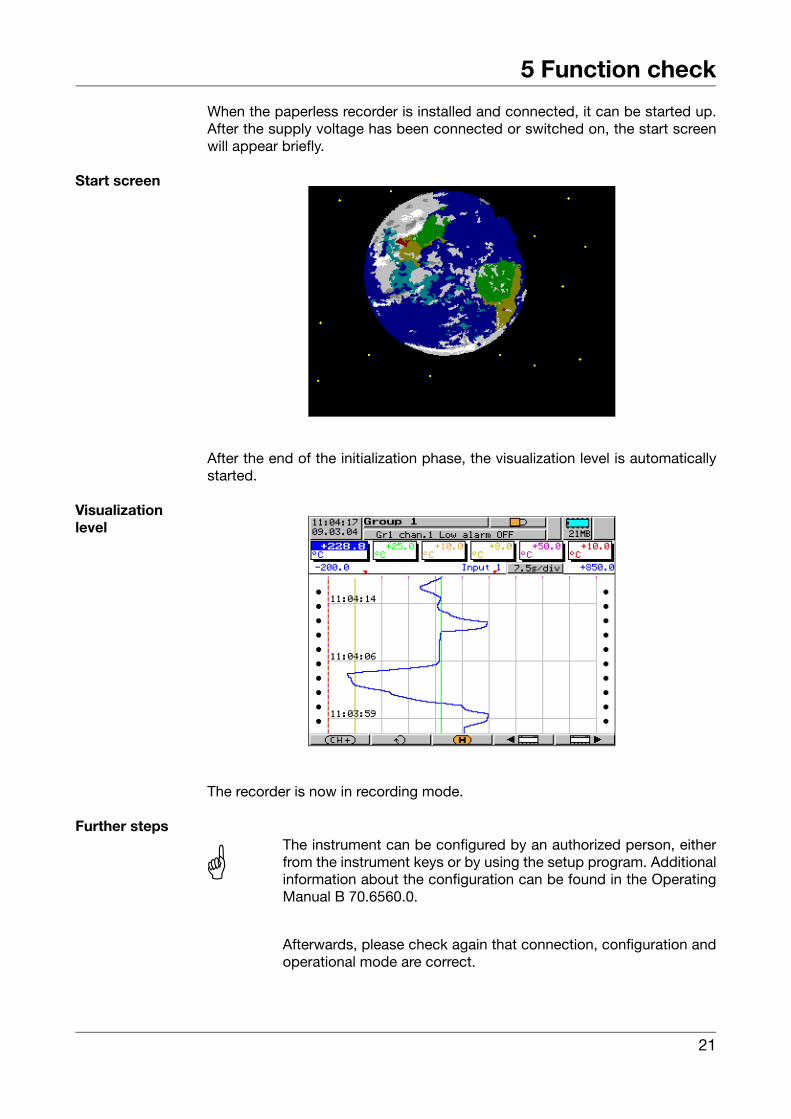
5 Function check
When the paperless recorder is installed and connected, it can be started up.After the supply voltage has been connected or switched on, the start screenwill appear briefly.
Start screen
After the end of the initialization phase, the visualization level is automaticallystarted.
Visualizationlevel
The recorder is now in recording mode.
Further steps
A
The instrument can be configured by an authorized person, eitherfrom the instrument keys or by using the setup program. Additionalinformation about the configuration can be found in the OperatingManual B 70.6560.0.
Afterwards, please check again that connection, configuration andoperational mode are correct.
21

5 Function check
22
6 Device replacement / software update
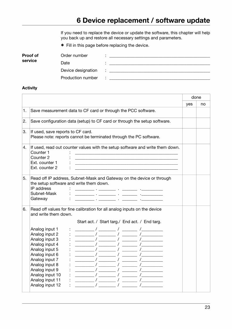
If you need to replace the device or update the software, this chapter will helpyou back up and restore all necessary settings and parameters.
h Fill in this page before replacing the device.
Proof ofservice
Order number : _______________________________________________
Date : _______________________________________________
Device designation : _______________________________________________
Production number : _______________________________________________
Activity
done
yes no
1. Save measurement data to CF card or through the PCC software.
2. Save configuration data (setup) to CF card or through the setup software.
3. If used, save reports to CF card. Please note: reports cannot be terminated through the PC software.
4. If used, read out counter values with the setup software and write them down.Counter 1 : ________________________________________________Counter 2 : ________________________________________________Ext. counter 1 : ________________________________________________Ext. counter 2 : ________________________________________________
5. Read off IP address, Subnet-Mask and Gateway on the device or throughthe setup software and write them down.IP address : _________ . ________ . _______ .__________Subnet-Mask : _________ . ________ . _______ .__________Gateway : _________ . ________ . _______ .__________
6. Read off values for fine calibration for all analog inputs on the device and write them down.
Start act. / Start targ./ End act. / End targ.
Analog input 1 : _________ / ________ / _______ /__________Analog input 2 : _________ / ________ / _______ /__________Analog input 3 : _________ / ________ / _______ /__________Analog input 4 : _________ / ________ / _______ /__________Analog input 5 : _________ / ________ / _______ /__________Analog input 6 : _________ / ________ / _______ /__________Analog input 7 : _________ / ________ / _______ /__________Analog input 8 : _________ / ________ / _______ /__________Analog input 9 : _________ / ________ / _______ /__________Analog input 10 : _________ / ________ / _______ /__________Analog input 11 : _________ / ________ / _______ /__________Analog input 12 : _________ / ________ / _______ /__________
23
6 Device replacement / software update
Info After uploading the user list, the users must log in with the password that wasinitially assigned by the administrator.If a user no longer knows the password, then the user status has to be set to“New” and a new password assigned through the PCS software.After altering the device software (update), the process data are stored in anew PCA3000 archive.
Notes
24
7 Technical data
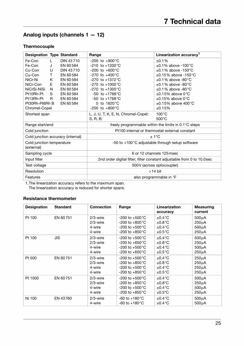
Analog inputs (channels 1 — 12)
Thermocouple
Resistance thermometer
Designation Type Standard Range Linearization accuracy1
Fe-Con L DIN 43 710Fe-Con J EN 60 584Cu-Con U DIN 43 710Cu-Con T EN 60 584NiCr-Ni K EN 60 584NiCr-Con E EN 60 584NiCrSi-NiSi N EN 60 584Pt10Rh-Pt S EN 60 584Pt13Rh-Pt R EN 60 584Pt30Rh-Pt6Rh B EN 60 584Chromel-Copel
-200 to +900°C-210 to +1200°C-200 to +600°C-270 to +400°C-270 to +1372°C-270 to +1000°C-270 to +1300°C
-50 to +1768°C-50 to +1768°C
0 to 1820°C-200 to +800°C
±0.1%±0.1% above -100°C±0.1% above -150°C±0.15% above -150°C±0.1% above -80°C±0.1% above -80°C±0.1% above -80°C±0.15% above 0°C±0.15% above 0°C±0.15% above 400°C±0.15%
Shortest span L, J, U, T, K, E, N, Chromel-Copel:S, R, B:
100°C500°C
Range start/end freely programmable within the limits in 0.1°C steps
Cold junction Pt100 internal or thermostat external constant
Cold junction accuracy (internal) ± 1°C
Cold junction temperature(external)
-50 to +100°C adjustable through setup software
Sampling cycle 6 or 12 channels 125msec
Input filter 2nd order digital filter; filter constant adjustable from 0 to 10.0sec
Test voltage 500V (across optocoupler)
Resolution >14 bit
Features also programmable in °F
1.The linearization accuracy refers to the maximum span.The linearization accuracy is reduced for shorter spans.
Designation Standard Connection Range Linearizationaccuracy
Measuringcurrent
Pt 100 EN 60 751 2/3-wire2/3-wire4-wire4-wire
-200 to +500°C-200 to +850°C-200 to +500°C-200 to +850°C
±0.4°C±0.8°C±0.4°C±0.5°C
500μA250μA500μA250μA
Pt 100 JIS 2/3-wire2/3-wire4-wire4-wire
-200 to +500°C-200 to +650°C-200 to +500°C-200 to +650°C
±0.4°C±0.8°C±0.4°C±0.5°C
500μA250μA500μA250μA
Pt 500 EN 60 751 2/3-wire2/3-wire4-wire4-wire
-200 to +500°C-200 to +850°C-200 to +500°C-200 to +850°C
±0.4°C±0.8°C±0.4°C±0.5°C
250μA250μA250μA250μA
Pt 1000 EN 60 751 2/3-wire2/3-wire4-wire4-wire
-200 to +500°C-200 to +850°C-200 to +500°C-200 to +850°C
±0.4°C±0.8°C±0.4°C±0.5°C
500μA250μA500μA250μA
Ni 100 EN 43760 2/3-wire4-wire
-60 to +180°C-60 to +180°C
±0.4°C±0.4°C
500μA500μA
25
7 Technical data
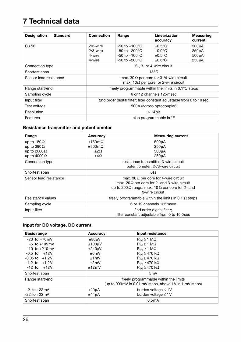
Resistance transmitter and potentiometer
Input for DC voltage, DC current
Designation Standard Connection Range Linearizationaccuracy
Measuringcurrent
Cu 50 2/3-wire2/3-wire4-wire4-wire
-50 to +100°C-50 to +200°C-50 to +100°C-50 to +200°C
±0.5°C±0.9°C±0.5°C±0.6°C
500μA250μA500μA250μA
Connection type 2-, 3- or 4-wire circuit
Shortest span 15°C
Sensor lead resistance max. 30 Ω per core for 3-/4-wire circuitmax. 10Ω per core for 2-wire circuit
Range start/end freely programmable within the limits in 0.1°C steps
Sampling cycle 6 or 12 channels 125msec
Input filter 2nd order digital filter; filter constant adjustable from 0 to 10sec
Test voltage 500V (across optocoupler)
Resolution > 14bit
Features also programmable in °F
Range Accuracy Measuring current
up to 180Ωup to 390Ωup to 2000Ωup to 4000Ω
±150mΩ±300mΩ
±2Ω±4Ω
500μA250μA500μA250μA
Connection type resistance transmitter: 3-wire circuitpotentiometer: 2-/3-wire circuit
Shortest span 6ΩSensor lead resistance max. 30Ω per core for 4-wire circuit
max. 20Ω per core for 2- and 3-wire circuitup to 200 Ω range: max. 10 Ω per core for 2- and
3-wire circuit
Resistance values freely programmable within the limits in 0.1 Ω steps
Sampling cycle 6 or 12 channels 125msec
Input filter 2nd order digital filter; filter constant adjustable from 0 to 10.0sec
Basic range Accuracy Input resistance
-20 to +70mV-5 to +105mV
-10 to +210mV-0.5 to +12V-0.05 to +1.2V-1.2 to +1.2V-12 to +12V
±80μV±100μV±240μV±6mV±1mV±2mV
±12mV
RIN ≥ 1 MΩRIN ≥ 1 MΩRIN ≥ 1 MΩRIN ≥ 470 kΩRIN ≥ 470 kΩRIN ≥ 470 kΩRIN ≥ 470 kΩ
Shortest span 5mV
Range start/end freely programmable within the limits(up to 999mV in 0.01 mV steps, above 1V in 1 mV steps)
-2 to +22mA-22 to +22mA
±20μA±44μA
burden voltage ≤ 1Vburden voltage ≤ 1V
Shortest span 0.5mA
26
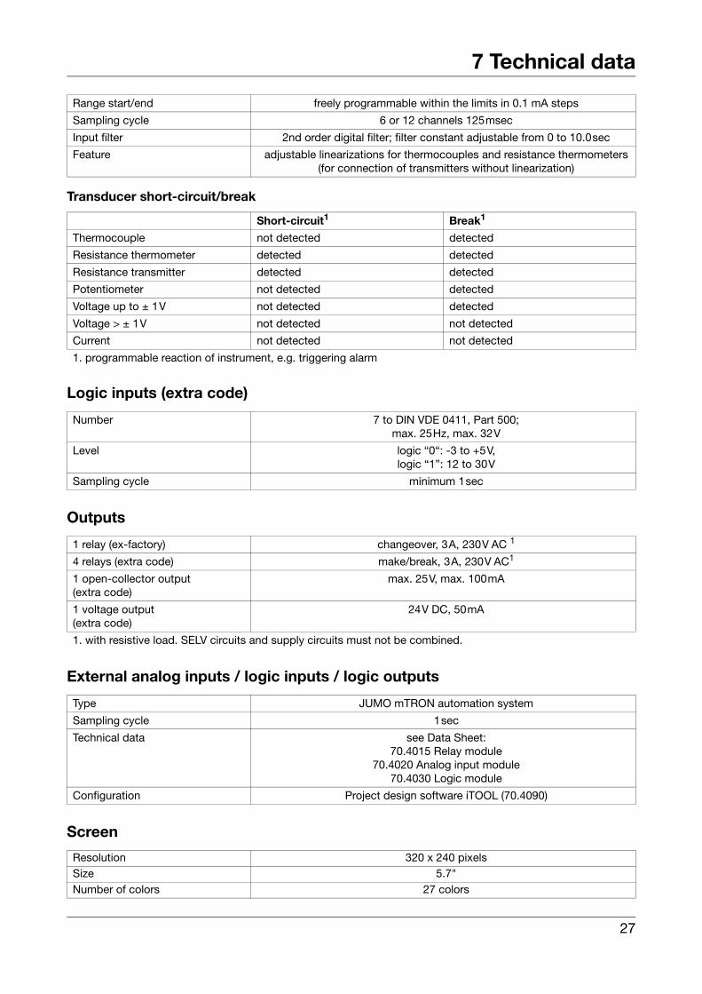
7 Technical data
Transducer short-circuit/break
Logic inputs (extra code)
Outputs
External analog inputs / logic inputs / logic outputs
Screen
Range start/end freely programmable within the limits in 0.1 mA steps
Sampling cycle 6 or 12 channels 125msec
Input filter 2nd order digital filter; filter constant adjustable from 0 to 10.0sec
Feature adjustable linearizations for thermocouples and resistance thermometers (for connection of transmitters without linearization)
Short-circuit1 Break1
Thermocouple not detected detected
Resistance thermometer detected detected
Resistance transmitter detected detected
Potentiometer not detected detected
Voltage up to ± 1V not detected detected
Voltage > ± 1V not detected not detected
Current not detected not detected
1. programmable reaction of instrument, e.g. triggering alarm
Number 7 to DIN VDE 0411, Part 500; max. 25Hz, max. 32V
Level logic “0“: -3 to +5V, logic “1”: 12 to 30V
Sampling cycle minimum 1sec
1 relay (ex-factory) changeover, 3A, 230V AC 1
4 relays (extra code) make/break, 3A, 230V AC1
1 open-collector output(extra code)
max. 25V, max. 100mA
1 voltage output(extra code)
24V DC, 50mA
1. with resistive load. SELV circuits and supply circuits must not be combined.
Type JUMO mTRON automation system
Sampling cycle 1sec
Technical data see Data Sheet: 70.4015 Relay module
70.4020 Analog input module70.4030 Logic module
Configuration Project design software iTOOL (70.4090)
Resolution 320 x 240 pixelsSize 5.7"Number of colors 27 colors
27
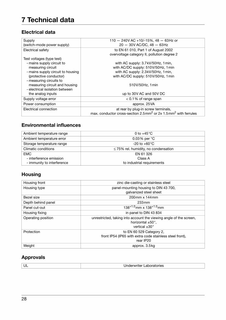
7 Technical data
Electrical data
Environmental influences
Housing
Approvals
Supply(switch-mode power supply)
110 — 240V AC +10/-15%, 48 — 63Hz or 20 — 30V AC/DC, 48 — 63Hz
Electrical safety
Test voltages (type test)- mains supply circuit to
measuring circuit- mains supply circuit to housing
(protective conductor)- measuring circuits to
measuring circuit and housing- electrical isolation between
the analog inputs
to EN 61 010, Part 1 of August 2002overvoltage category II, pollution degree 2
with AC supply: 3.7kV/50Hz, 1min,with AC/DC supply: 510V/50Hz, 1min
with AC supply: 2.3kV/50Hz, 1min,with AC/DC supply: 510V/50Hz, 1min
510V/50Hz, 1min
up to 30V AC and 50V DCSupply voltage error < 0.1% of range spanPower consumption approx. 25VAElectrical connection at rear by plug-in screw terminals,
max. conductor cross-section 2.5mm2 or 2x 1.5mm2 with ferrules
Ambient temperature range 0 to +45°CAmbient temperature error 0.03% per °CStorage temperature range -20 to +60°C Climatic conditions ≤ 75% rel. humidity, no condensationEMC
- interference emission- immunity to interference
EN 61 326Class A
to industrial requirements
Housing front zinc die-casting or stainless steelHousing type panel-mounting housing to DIN 43 700,
galvanized steel sheetBezel size 200mm x 144mmDepth behind panel 233mmPanel cut-out 138+1.0mm x 138+1.0mmHousing fixing in panel to DIN 43 834Operating position unrestricted, taking into account the viewing angle of the screen,
horizontal ±50°, vertical ±30°
Protection to EN 60 529 Category 2,front IP54 (IP65 with extra code stainless steel front),
rear IP20Weight approx. 3.5kg
UL Underwriter Laboratories
28
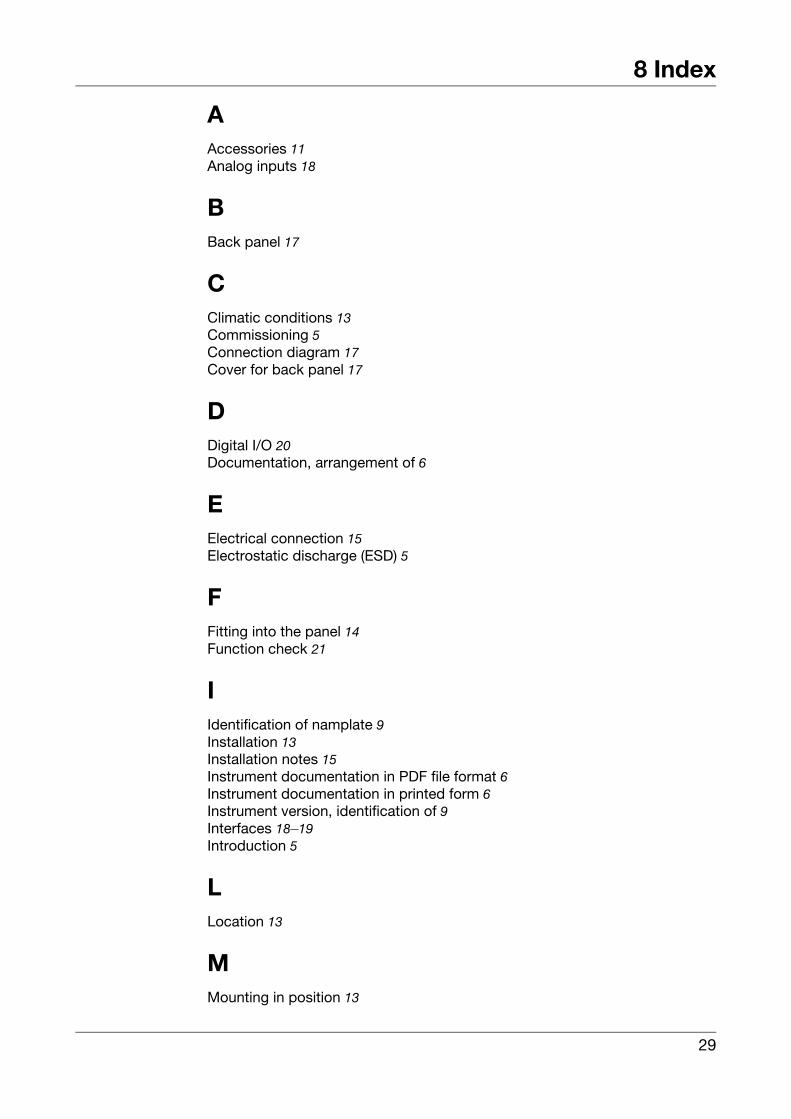
8 Index
AAccessories 11Analog inputs 18
BBack panel 17
CClimatic conditions 13Commissioning 5Connection diagram 17Cover for back panel 17
DDigital I/O 20Documentation, arrangement of 6
EElectrical connection 15Electrostatic discharge (ESD) 5
FFitting into the panel 14Function check 21
IIdentification of namplate 9Installation 13Installation notes 15Instrument documentation in PDF file format 6Instrument documentation in printed form 6Instrument version, identification of 9Interfaces 18–19Introduction 5
LLocation 13
MMounting in position 13
29
8 Index
NNameplate 9Note signs 8
OOutline drawings 13
PPROFIBUS-DP 10, 19
RRear view 17Relay outputs 19Repeat order for recorder in the identical version 9Returning 5
SSales documentation in printed form 6Standard accessories 11Start screen 21Supply 18
TTechnical data 25Type designation 10Typographical conventions 8
VVisualization level 21
WWarning signs 8Warranty 5
30


JUMO GmbH & Co. KGStreet address:Moltkestraße 13 - 3136039 Fulda, GermanyDelivery address:Mackenrodtstraße 1436039 Fulda, GermanyPostal address:36035 Fulda, GermanyPhone: +49 661 6003-0Fax: +49 661 6003-607e-mail: [email protected]: www.jumo.net
JUMO Instrument Co. Ltd.JUMO HouseTemple Bank, RiverwayHarlow, Essex CM20 2TT, UKPhone: +44 1279 635533Fax: +44 1279 635262e-mail: [email protected]: www.jumo.co.uk
JUMO Process Control, Inc.8 Technology BoulevardCanastota, NY 13032, USAPhone: 315-697-JUMO
1-800-554-JUMOFax: 315-697-5867e-mail: [email protected]: www.jumo.us


![Paperless Recorder GX10 - Yokogawa Paperless Recorder GX10 Unit: mm (approx. inch) SD 04L51B01-01EN [ Main Unit ] External Dimensions *1: with modules *2: without moduels Unless otherwise](https://img.pdfslide.us/doc/110x75/5b276dbd7f8b9a34208b6391/paperless-recorder-gx10-yokogawa-paperless-recorder-gx10-unit-mm-approx-inch.jpg)