Embed Size (px)
Citation preview

ERT 210/4Process Control & Dynamics
CHAPTER 10OVERVIEW OF CONTROL
SYSTEM DESIGN
Hairul Nazirah bt Abdul HalimEmail:
[email protected]: 04-9798840

Overview of Control System Design C
hap
ter
10
1. Safety - industrial plants operate safely so as to promote the well-being of people and equipment within the plant and in the nearby communities.
2. Environmental Regulations - Industrial plants must comply with environmental regulations concerning the discharge of gases, liquids, and solids beyond the plant boundaries.
3. Product Specifications and Production Rate. In order to be profitable, a plant must make products that meet specifications concerning product quality and production rate.
General Control Objectives

Ch
apte
r 10
4. Economic Plant Operation - the plant operation over long periods of time must be profitable. Thus, the control objectives must be consistent with the economic objectives.
5. Stable Plant Operation. The control system should facilitate smooth, stable plant operation without excessive oscillation in key process variables. Thus, it is desirable to have smooth, rapid set-point changes and rapid recovery from plant disturbances such as changes in feed composition.

Ch
apte
r 10
Steps in Control System Design
The design procedure consists of three main steps:
1. Select controlled, manipulated, and measured variables.
2. Choose the control strategy and the control structure
3. Specify controller settings & tuning

Control Strategies
• Multiloop Control:
- Each output variable is controlled using a single input variable.
- Consist of a set of PI or PID controllers, one for each controlled variable.
Ch
apte
r 10

Control Strategies• Multivariable Control:
Each manipulated variable is adjusted based on measurements of two or more controlled variables.
Eg. Adjust the feed flow rate to control product flow rate and product composition.
Ch
apte
r 10

10.2 THE INFLUENCE OF PROCESS DESIGN ON PROCESS CONTROL
• Traditionally, process design and control system design have been separate engineering activities.
• The control system design is initiated after the plant design is well underway
• This approach has serious limitations because the plant design determines the process dynamic characteristics, as well as the operability of the plant.
Ch
apte
r 10

• In extreme situations, the plant may be uncontrollable even though the process design appears satisfactory from a steady-state point of view.
• A more desirable approach is to consider process dynamics and control issues early in the plant design.
• This interaction between design and control has become especially important for modern processing plants.
(continued)
Ch
apte
r 10

As Hughart and Kominek (1977) have noted:
"The control system engineer can make a major contribution to a project by advising the project team on how
process design will influence the process dynamics and the control structure.”
Ch
apte
r 10

Heat Integration of Process Units
Ch
apte
r 10
Figure 10.1 Schematic for conventional distillation system.

• Heat integration - reduce the energy cost
• Thermal coupling of two or more column
• Heat integration reduces energy costs by allowing the overhead steam from Column 1 to be used as the heating medium in the reboiler for Column 2.C
hap
ter
10
Ch
apte
r 10
Figure 10.1 Two distillation column configurations.

• However, this column configuration is more difficult to control for two reasons:
a) process upsets in one column affect the other column
b) heat integration configuration has one less manipulated variable available for process control because the reboiler heat duty for Column 2 can no longer be independently manipulated.
• These disadvantages can be reduced by adding a trim reboiler. It has a separate supply of the heating medium that can be manipulated.
Ch
apte
r 10
Ch
apte
r 10
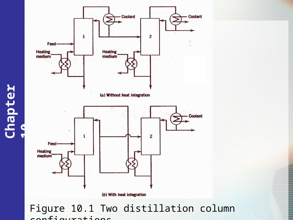
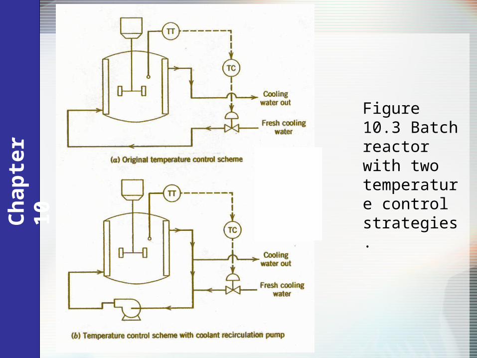
Figure 10.3 Batch reactor with two temperature control strategies.
• The configuration in Fig. 10.3a has a serious disadvantages that the coolant circulation rate varies.
• Thus the corresponding time delay for the coolant loop also varies.
• Results in nonlinear oscillation during process.• If the reactor temperature increases, the
controller increases the coolant flow rate, which reduces the time delay.
Ch
apte
r 10

• When the reactor temperature is too low, the controller reduces the coolant flow rate, which increase the time delay.
• This conditions results in a slow response.• This control problem can be solved as shown in
Fig. 10.3b. – add recirculation pump• The recirculation rate and process time are kept
constant and thus are independent of the flow rate of fresh cooling water.
Ch
apte
r 10
Ch
apte
r 10
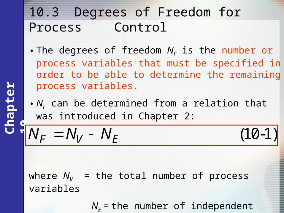
• The degrees of freedom NF is the number or process variables that must be specified in order to be able to determine the remaining process variables.
• NF can be determined from a relation that was introduced in Chapter 2:
(10-1)F V EN N N
where NV = the total number of process variables
NE = the number of independent equations.
10.3 Degrees of Freedom for Process Control

Ch
apte
r 10
Definition. The control degrees of freedom, NFC, is the number of process variables (e.g., temperatures, levels, flow rates, compositions) that can be independently controlled.

Ch
apte
r 10
• In order to make a clear distinction between NF and NFC, we will refer to:
• NF as the model degrees of freedom
• NFC as the control degrees of freedom.
• Note that NF and NFC are related by the following equation,
(10-2)F FC DN N N
where ND is the number of disturbance variables (i.e., input variables that cannot be manipulated.)
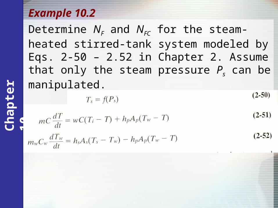
Determine NF and NFC for the steam-heated stirred-tank system modeled by Eqs. 2-50 – 2.52 in Chapter 2. Assume that only the steam pressure Ps can be manipulated.
Example 10.2C
hap
ter
10
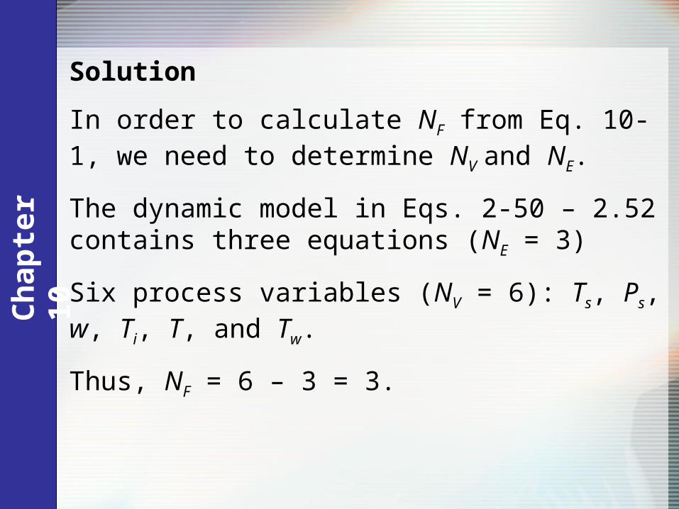
Solution
In order to calculate NF from Eq. 10-1, we need to determine NV and NE.
The dynamic model in Eqs. 2-50 – 2.52 contains three equations (NE = 3)
Six process variables (NV = 6): Ts, Ps, w, Ti, T, and Tw.
Thus, NF = 6 – 3 = 3.
Ch
apte
r 10
Ch
apte
r 10
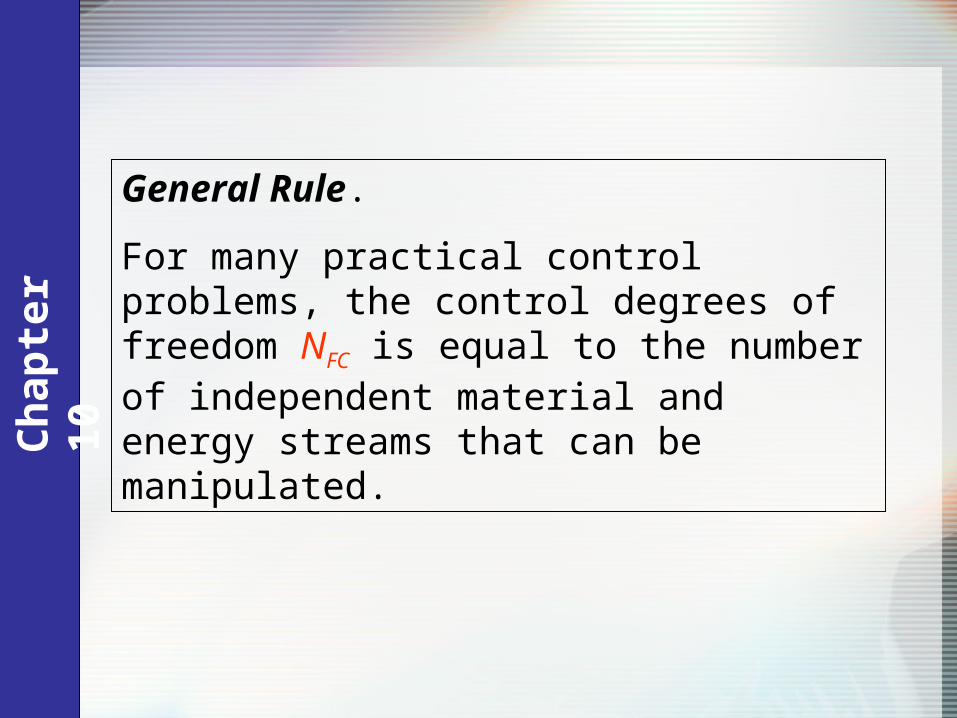
General Rule.
For many practical control problems, the control degrees of freedom NFC is equal to the number of independent material and energy streams that can be manipulated.

Stirred-Tank Heating Process
Figure 2.3 Stirred-tank heating process with constant holdup, V.
Ch
apte
r 10
Ch
apte
r 10
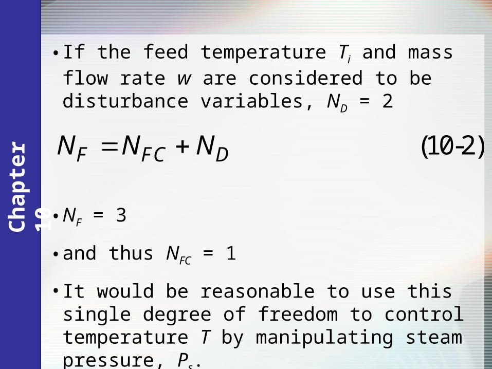
• If the feed temperature Ti and mass flow rate w are considered to be disturbance variables, ND = 2
• NF = 3
• and thus NFC = 1
• It would be reasonable to use this single degree of freedom to control temperature T by manipulating steam pressure, Ps.
(10-2)F FC DN N N

Ch
apte
r 10
Selection of Controlled, Manipulated & Measured Variables
• Process variables can be classified into input variables and output variables.
• Definition of input variables: physical variables that affect the output variables.
• Input variables can be divided into manipulated variables and disturbance variables.
• Manipulated variables are typically flow rates• Common disturbance variables include the feed
conditions to a process and the ambient temperature.• The output variables are process variables that typically
are associated with exit streams (e.g. compositions, temperatures, levels and flow rates).

Ch
apte
r 10
Selection of Controlled Variables
Guideline 1.
All variables that are not self-regulating must be controlled.
-Non self-regulating variable: an output variable that exhibits an unbounded response after a sustained disturbance.
-must be controlled in order for control process to be stable.
Guideline 2.
Choose output variables that must be kept within equipment and operating constraints (e.g., temperatures, pressures, and compositions).
Ch
apte
r 10
Guideline 3.
Select output variables that are a direct measure of product quality (e.g., composition, refractive index) or that strongly affect it (e.g., temperature or pressure).
Guideline 4.
Choose output variables that seriously interact with other controlled variables.
Guideline 5.
Choose output variables that have favorable dynamic and static characteristics.

Ch
apte
r 10
Guideline 6.
Select inputs that have large effects on controlled variables.
Guideline 7.
Choose inputs that rapidly affect the controlled variables.
Guideline 8.
The manipulated variables should affect the controlled variables directly rather than indirectly.
Guideline 9.
Avoid recycling of disturbances.
Selection of Manipulated Variables

Ch
apte
r 10
Guideline 10.
Reliable, accurate measurements are essential for good control.
Guideline 11.
Select measurement points that have an adequate degree of sensitivity.
Guideline 12.
Select measurement points that minimize time delays and time constants
Selection of Measured Variables