Embed Size (px)
Citation preview

©2006 ASHRAE. All Rights reserved.
ERRATA SHEET FOR ANSI/ASHRAE STANDARD 79-2002 (RA 2006)
Method of Testing for Rating Fan-Coil Conditioners
June 8, 2006
The corrections listed in this errata sheet apply to all copies of ANSI/ASHRAE Standard 79-2002 (RA 2006).
Page Erratum
10 Section 8.1.1. Revise the SI equation for “v΄n” from v1 101 273 + tan v΄n = ---------- x ---------- x ----------
( 1 + W1 Pb + Pv 273 + ta1
) to
v1 101 273 + tan v΄n = ---------- x -------------- x ----------
Pv Pb + -------
( 1 + W1
1000
273 + ta1
)
www.TeraStandard.com
--`,````,`,,````,,``,,``,`,`,,-`-`,,`,,`,`,,`---

ASHRAE STANDARDASHRAE STANDARD
American Society of Heating, Refrigeratingand Air-Conditioning Engineers, Inc.
1791 Tullie Circle NE, Atlanta, GA 30329www.ashrae.org
Method of Testing forRating Fan-CoilConditioners
ANSI/ASHRAE Standard 79-2002 (RA 2006)Reaffirmation of ANSI/ASHRAE Standard 79-2002
Approved by the ASHRAE Standards Committee on January 16, 2002, and reaffirmed on January 21, 2006; by theASHRAE Board of Directors on January 16, 2002, and reaffirmed on January 26, 2006; and by the AmericanNational Standards Institute on February 20, 2002, and reaffirmed on January 27, 2006.
ASHRAE Standards are scheduled to be updated on a five-year cycle; the date following the standard number isthe year of ASHRAE Board of Directors approval. The latest copies may be purchased from ASHRAE CustomerService, 1791 Tullie Circle, NE, Atlanta, GA 30329-2305. E-mail: [email protected]. Fax: 404-321-5478. Tele-phone: 404-636-8400 (worldwide) or toll free 1-800-527-4723 (for orders in US and Canada).
© Copyright 2006 ASHRAE, Inc.
ISSN 1041-2336
When addenda, interpretations, or errata to this standard have been approved, they can be downloaded free ofcharge from the ASHRAE Web site at http://www.ashrae.org.
www.TeraStandard.com
--`,````,`,,````,,``,,``,`,`,,-`-`,,`,,`,`,,`---

ASHRAE Standing Standard Project Committee 79Cognizant TC: TC 9.1, Large Building Air Conditioning Systems
SPLS Liaison: Steven D. Taylor
Charles E. Henck, Chair* Trenwith R. Ward*
Warren G. Hahn* Wayne L. White*
Boggam S. Setty* Harry M. WIll*
* Denotes members of voting status when the document was approved for publication.
ASHRAE STANDARDS COMMITTEE 2005-2006
Richard D. Hermans, ChairDavid E. Knebel, Vice-ChairDonald L. BrandtSteven T. BushbyPaul W. CabotHugh F. CrowtherSamuel D. Cummings, Jr.Robert G. DoerrHakim ElmahdyRoger L. HedrickJohn F. HoganFrank E. JakobStephen D. Kennedy
Jay A. KohlerJames D. Lutz
Merle F. McBrideMark P. Modera
Cyrus H. NasseriStephen V. SantoroStephen V. Skalko
David R. TreeJerry W. White, Jr.
James E. WoodsWilliam E. Murphy, BOD ExO
Ronald E. Jarnagin, CO
Claire B. Ramspeck, Assistant Director of Technology for Standards and Special Projects
SPECIAL NOTE
This American National Standard (ANS) is a national voluntary consensus standard developed under the auspices of the AmericanSociety of Heating, Refrigerating and Air-Conditioning Engineers (ASHRAE). Consensus is defined by the American National StandardsInstitute (ANSI), of which ASHRAE is a member and which has approved this standard as an ANS, as “substantial agreement reached bydirectly and materially affected interest categories. This signifies the concurrence of more than a simple majority, but not necessarily unanimity.Consensus requires that all views and objections be considered, and that an effort be made toward their resolution.” Compliance with thisstandard is voluntary until and unless a legal jurisdiction makes compliance mandatory through legislation.
ASHRAE obtains consensus through participation of its national and international members, associated societies, and public review.ASHRAE Standards are prepared by a Project Committee appointed specifically for the purpose of writing the Standard. The Project
Committee Chair and Vice-Chair must be members of ASHRAE; while other committee members may or may not be ASHRAE members, allmust be technically qualified in the subject area of the Standard. Every effort is made to balance the concerned interests on all ProjectCommittees.
The Manager of Standards of ASHRAE should be contacted for:a. interpretation of the contents of this Standard,b. participation in the next review of the Standard,c. offering constructive criticism for improving the Standard,d. permission to reprint portions of the Standard.
DISCLAIMER
ASHRAE uses its best efforts to promulgate Standards and Guidelines for the benefit of the public in light of available information and acceptedindustry practices. However, ASHRAE does not guarantee, certify, or assure the safety or performance of any products, components, orsystems tested, installed, or operated in accordance with ASHRAE’s Standards or Guidelines or that any tests conducted under its Standardsor Guidelines will be nonhazardous or free from risk.
ASHRAE INDUSTRIAL ADVERTISING POLICY ON STANDARDS
ASHRAE Standards and Guidelines are established to assist industry and the public by offering a uniform method of testing for ratingpurposes, by suggesting safe practices in designing and installing equipment, by providing proper definitions of this equipment, and by providingother information that may serve to guide the industry. The creation of ASHRAE Standards and Guidelines is determined by the need for them,and conformance to them is completely voluntary.
In referring to this Standard or Guideline and in marking of equipment and in advertising, no claim shall be made, either stated or implied,that the product has been approved by ASHRAE.
www.TeraStandard.com
--`,````,`,,````,,``,,``,`,`,,-`-`,,`,,`,`,,`---

CONTENTS
ANSI/ASHRAE Standard 79-2002 (RA 2006)Method of Testing for Rating Fan-Coil Conditioners
SECTION PAGE
Foreword................................................................................................................................................................... 2
1 Purpose and Scope ........................................................................................................................................ 2
2 Definitions....................................................................................................................................................... 2
3 Test Conditions............................................................................................................................................... 2
4 Test Instruments............................................................................................................................................. 2
5 Test Apparatus ............................................................................................................................................... 4
6 Installation of Fan Coil Under Test ................................................................................................................. 8
7 Test Methods and Procedures ....................................................................................................................... 9
8 Calculations .................................................................................................................................................. 10
9 Reference Properties and Data .................................................................................................................... 13
10 References ................................................................................................................................................... 14
NOTE
When addenda, interpretations, or errata to this standard have been approved, they can be downloaded free of charge from the ASHRAE Web site at http://www.ashrae.org.
© Copyright 2006 American Society of Heating,Refrigerating and Air-Conditioning Engineers, Inc.
1791 Tullie Circle NEAtlanta, GA 30329www.ashrae.org
All rights reserved.
www.TeraStandard.com
--`,````,`,,````,,``,,``,`,`,,-`-`,,`,,`,`,,`---
2 ANSI/ASHRAE Standard 79-2002 (RA 2006)
(This foreword is not part of this standard. It is merelyinformative and does not contain requirements necessaryfor conformance to the standard. It has not beenprocessed according to ANSI requirements for astandard and may contain material that has not beensubject to public review or a consensus process.)
FOREWORD
This is a reaffirmation of ASHRAE Standard 79-2002. Thisstandard falls under the Standards Committee classification ofStandard Method of Measurement. This standard was preparedunder the auspices of the American Society of Heating, Refrig-erating and Air-Conditioning Engineers (ASHRAE). It may beused, in whole or in part, by an association or governmentagency with due credit to ASHRAE. Adherence is strictly on avoluntary basis and merely in the interests of obtaining uniformstandards throughout the industry.
This standard prescribes testing methods for the capacityof fan-coil units.
The changes made for the 2006 reaffirmation wereupdates to the references.
1. PURPOSE AND SCOPE
1.1 PurposeThe purpose of this standard is to prescribe laboratory
methods of testing room fan-coil air conditioners to ensureuniform performance data for establishing ratings.
1.2 ScopeThis standard includes procedures that
1. describe and specify test instruments and apparatus,2. describe and specify laboratory test methods and proce-
dures,3. describe and specify test data to be recorded,4. describe and specify calculations to be made from test data,5. define terms used in testing, and6. specify standard thermodynamic properties.
2. DEFINITIONS
room fan-coil air conditioner (hereinafter referred to as fancoil): a factory-made assembly that provides the functions offorced circulation, cooling or cooling and heating, and filter-ing of air, but does not include the source of cooling or heating.This device is normally designed for free delivery of air intoa room but may be applied with minimal ductwork having astatic resistance generally not exceeding 0.25 in. of water(62 Pa). This device may be designed for furred-in applicationor with an enclosure for application within the conditionedspace. This device is generally designed in sizes of air deliverycapacity of 2,000 cfm (944 L/s) or less.
equilibrium: for the purposes of this standard, a steady-statecondition during which the fluctuations of variables beingmeasured remain within the test tolerances given in Table 1.
evaporative equilibrium: the condition attained on a wet-bulbinstrument when the wetted wick has reached a stable andconstant temperature.
test: the recorded group of readings of required test data takenwhile equilibrium is maintained and used in the computationof results:
1. those observed or recorded during a sufficient period toindicate that equilibrium was attained prior to the actual testand
2. those recorded during the period of the test.
test run: the complete group of readings of required test data,which include:
total cooling capacity: the rate, expressed in Btu/h (W), atwhich the fan coil under test reduces the enthalpy of the airpassing through it.
sensible capacity: the rate, expressed in Btu/h (W), at whichthe fan coil under test reduces or increases the dry-bulbtemperature of the air passing through it.
latent cooling capacity: the rate, expressed in Btu/h (W), atwhich the fan coil under test reduces the moisture content ofthe air passing through it.
standard air: air weighing 0.075 lb/ft3 (1.2 kg/m3), whichapproximates dry air at 70°F (21.1°C) and at standard baro-metric pressure.
standard barometric pressure: a barometric pressure of29.92 in. Hg (101 kPa).
forced circulation of air: air circulation caused by a differencein static pressure produced by an air-moving device.
3. TEST CONDITIONS
3.1 Variations. The methods provided in this standard maybe used to determine fan-coil performance at various test con-ditions that may be prescribed in other standards or specifica-tions.
3.2 Tolerances. In all cases, the test conditions shall bemaintained within the tolerances specified in Section 8.6 dur-ing the prescribed test period.
4. TEST INSTRUMENTS
4.1 Temperature-Measuring Instruments
4.1.1 Types of Instruments. Temperature measurementsshall be made with one or more of the following instruments:
1. Mercury-in-glass thermometers2. Thermocouples3. Electric resistance thermometers
4.1.2 Accuracy and Precision of the temperature-mea-suring instruments shall be within the following limits:
Instrument Accuracy
InstrumentPrecision
(1) Wet- and dry-bulb temperatures
±0.2°F ±0.1°C ±0.1°F ±0.05°C
(2) Water temperatures ±0.15°F ±0.08°C ±0.1°F ±0.05°C
(3) Nozzle air temperatures ±1.0°F ±0.5°C ±1.0°F ±0.5°C
(4) All other temperatures ±0.5°F ±0.3°C ±0.5°F ±0.3°C
www.TeraStandard.com
--`,````,`,,````,,``,,``,`,`,,-`-`,,`,,`,`,,`---
ANSI/ASHRAE Standard 79-2002 (RA 2006) 3
4.1.3 Scale Division. In no case shall the smallest scaledivision of the temperature-measuring instrument exceedtwice the specified precision.
4.1.4 Calibration Standards. Where an accuracy closerthan ±0.5°F (±0.3°C) is specified, the instrument shall be cal-ibrated by comparison with a certified (National Institute ofStandards and Technology) standard in the range of use orshall be certified as to accuracy.
4.1.5 Air Temperature4.1.5.1 Dry-bulb. Dry-bulb temperature shall be read
only under conditions that ensure an air velocity of not lessthan 700 fpm (3.5 m/s) and only after sufficient time has beenallowed for equilibrium.
4.1.5.2 Wet-bulb. Wet-bulb temperatures shall be readonly under conditions that ensure an air velocity of approxi-mately 1000 fpm (5 m/s), but not more than 2000 fpm(10 m/s) or less than 700 fpm (3.5 m/s), over the wet bulb andonly after sufficient time has been allowed for equilibrium tobe attained. The wick on the wet-bulb thermometer shall beclean, fit the thermometer tightly, and be moistened by dis-tilled water. Wet-bulb thermometers shall always be down-stream from dry-bulb thermometers; and, if thesethermometers are side by side, they shall be shielded fromeach other.
4.1.5.3 Water Temperature. Water temperature withinconduits may be measured by inserting the temperature-mea-suring instrument directly into the water parallel to andagainst the flow. Where mercury-in-glass thermometers areused for water-temperature measurements, pressure correc-tions shall be applied to the temperature readings. Typically,these corrections are in the order of 0.012°F per psi(0.001°C/kPa) and are to be subtracted from each of the aver-age readings taken during the test. An acceptable alternatemethod of water-temperature measurement is with a liquid-filled well inserted into the conduit.
4.1.5.4 Interchangeability of Instruments. Whereverpossible, temperature-measuring instruments used to measurethe change in temperature of water or air shall be arranged sothat they can readily be interchanged between inlet and outletpositions after every reading, so as to improve accuracy.
4.2 Pressure Measurement4.2.1 Air Velocity Pressure. Air measurements at the air-
measuring nozzle throat or the static pressure differenceacross the air-measuring nozzle and the plenum chamberstatic pressure shall be made with inclined manometers. Themanometers shall be calibrated against a micromanometer orhook gauge to within ±0.005 in. of water (1.25 Pa). In no caseshall the smallest scale division of a manometer exceed 0.01in. of water (2.5 Pa).
4.2.2 Air Static Pressure. Measurement in the dischargechamber shall be made with an inclined manometer or micro-manometer. An inclined manometer shall be calibratedagainst a micromanometer or hook gauge to within 0.005 in.of water (1.25 Pa). In no case shall the smallest scale divisionof the air-pressure-measuring instrument exceed 0.01 in. ofwater (2.5 Pa).
4.2.3 Water-Pressure Measurement
4.2.3.1 Pressure for Differential Reading. Except formeasurement made for water pressure effect on temperaturemeasurement, water-pressure differential measurement shallbe made with a manometer with suitable liquid fill to give theaccuracy required. The accuracy of the manometer shall per-mit measurement within ±5% of the reading, and in no caseshall the smallest scale division of the manometer exceed 10%of the reading.
4.2.3.2 Pressure for Effect on Thermometers. Water-pressure measurement that is made for the purpose of deter-mining the water pressure effect on water-temperature mea-surement as defined in Section 4.1.6 shall be made withBourdon tube gauge. The smallest scale division of the gaugeshall be 1% of gauge reading. The Bourdon tube gauge shallbe calibrated with respect to a deadweight tester or by com-parison with a mercury column.
4.3 Airflow Measurement
4.3.1 Type of Instruments. Airflow measurement shallbe made either by measuring static pressure drop across oneor more nozzles with a manometer or by measuring the veloc-ity pressure at each nozzle with a pitot tube and manometer.
4.3.2 Nozzles
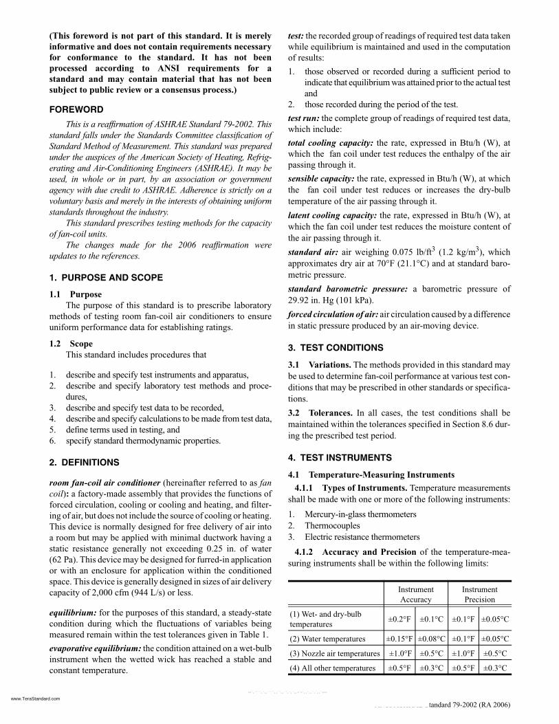
4.3.2.1 Construction. Construction of nozzles shall bein accordance with Figure 1. Nozzles shall be of a size suchthat the throat velocity is not less than 3000 fpm (15 m/s) ormore than 7000 fpm (36 m/s). When nozzles are constructedin accordance with Figure 1 and installed in accordance withSection 5.1.1, they may be used without calibration. If thethroat diameter is 5 in. (125 mm) or larger, the coefficient maybe assumed to be 0.99. For nozzles smaller than 5 in. (125mm) in diameter, or where a more precise coefficient isdesired, the value shown in Figure 1 or as determined usingthe nomograph of Figure 8 may be used.
Figure 1 Airflow-measuring nozzle.
www.TeraStandard.com
--`,````,`,,````,,``,,``,`,`,,-`-`,,`,,`,`,,`---

4 ANSI/ASHRAE Standard 79-2002 (RA 2006)
Reynolds Number is calculated as follows:
NRe = fVaD
whereVa = velocity of air at nozzle, fpm (m/s), and D = diameter, nozzle throat, in. (mm).
The temperature factor f is as follows:
4.3.2.2 Areas. Areas of a nozzle shall be computed fromthe average of diameter measurements made to an accuracy of±0.20% in four places approximately 45° apart around thenozzle in each of two planes through the nozzle throat, one atthe outlet and the other in the straight section near the radius.
4.3.3 Pitot Tubes. Pitot tubes shall be of the acceptedcommercial type.
4.4 Water-Flow Measurement. Water-flow measurementshall be made with one or more of the following instrumentshaving an accuracy of ±1.0% for the temperatures and quan-tities involved:
a. Liquid quantity meter measuring either weight or volume.b. Liquid flow meter.
4.5 Other Measurement
4.5.1 Time. Time shall be measured with an instrumentwhose accuracy is within ±0.5% of the value being observed.
4.5.2 Weight. Weight shall be measured with an instru-ment whose accuracy is within ±0.5% of the value beingobserved.
4.5.3 Electrical. Electrical measurements shall be madewith indicating instruments whose accuracy is within ±1.0%of the value being observed.
4.5.4 Fan speed. Fan speed measurements shall be madewith instruments whose accuracy is within ±2.0% of the valuebeing observed.
5. TEST APPARATUS
5.1 Airflow- and Temperature-Measuring Facilities5.1.1 Airflow- and Temperature-Measuring Appara-
tus5.1.2 General Description. Airflow rate, static pressure,
and wet- and dry-bulb temperatures leaving the fan coil undertest shall be measured with the apparatus illustrated inFigure 2. The airflow through this apparatus is described asfollows.
1. Air flows into a plenum chamber attached to output of thefan coil under test. A manometer shall be connected to theplenum chamber to indicate the static pressure within theplenum chamber.
2. The air then enters the mixing chamber. Upon leaving themixing chamber, the air passes through the mixing deviceand enters the receiving chamber.
3. The air then flows through the receiving chamber wherewet- and dry-bulb temperatures are measured with an air-sampling psychrometer.
4. Upon leaving the receiving chamber, the air enters theairflow-measuring nozzle. The air flows through the nozzleand into the discharge chamber. In the discharge chamber,the air passes through a diffusion baffle when required.
5. The air leaves the discharge chamber and enters the exhaustfan.
5.1.2.1 Plenum Chamber. Plenum chamber manome-ters shall have a minimum of four static pressure taps 90°apart and located flush with the inner walls of the plenumchamber. The individual reading of static pressure shall bechecked to ensure that the pressure difference between thepressure taps does not exceed 0.005 in. of water (1.25 Pa).
Reynolds Number, NRe Coefficient of Discharge, C
50,000 0.97
100,000 0.98
150,000 0.98
200,000 0.99
250,000 0.99
300,000 0.99
400,000 0.99
500,000 0.99
Temperature
Factor F°F °C
20 –6.7 10.1 (78.2)
40 4.4 9.3 (72.0)
60 15.6 8.7 (67.4)
80 26.7 8.1 (62.8)
100 37.8 7.5 (58.1)
120 48.9 7.1 (55.0)
140 60.0 6.7 (51.9)
160 71.1 6.3 (48.8)
Figure 2 Airflow- and temperature-measuringapparatus.
www.TeraStandard.com
--`,````,`,,````,,``,,``,`,`,,-`-`,,`,,`,`,,`---

ANSI/ASHRAE Standard 79-2002 (RA 2006) 5
5.1.2.2 Mixing Chamber. The mixing chamber shallcontain deflectors, vanes, or other means for mixing the air tothe extent that air temperatures measured across the cross sec-tion at the plane of measurement do not differ more than 1.0°F(0.5°C).
5.1.2.3 Receiving Chamber
1. Wet-bulb and dry-bulb temperatures shall be measured byone of the following methods:a. Temperatures shall be measured by the use of an air-
sampling psychrometer in the outlet opening of themixing chamber.
b. The temperatures shall be measured by temperature-measuring instruments inserted directly in an open-ing or openings, located at the outlet of the mixingchamber, so restricted that air velocities stipulated inSection 4.1.5 are met.
2. The receiving chamber shall provide uniform approachvelocity to the airflow-measuring nozzles or shall have suit-able diffusion baffles located at least 1.5 nozzle diameters(based on the largest nozzle diameter) upstream from thenozzle or nozzles to accomplish the purpose. The maxi-mum velocity shall not exceed 600 fpm (3 m/s), and themaximum average velocity shall not exceed 400 fpm(2 m/s). The cross-sectional area of the receiving chamberperpendicular to the axis of the nozzles shall be not less than12 times the area of the nozzles installed. The receivingchamber may be provided with a well-gasketed door orremovable side panel.
5.1.2.4 Nozzle Arrangement. Nozzles constructed inaccordance with Section 4.3.2 shall be fitted into one wall ofthe receiving chamber discharging into the discharge cham-ber. Center-to-center distances between nozzles in use shallbe not less than three throat diameters, and the distance fromthe center of any nozzles to any adjacent side wall shall be notless than 1.5 throat diameters. If the nozzles are of differentdiameters, the distance between axes shall be based upon thediameter of the largest nozzle.
5.1.2.5 Discharge Chamber Construction. Walls shallbe smooth and direct continuations of those of the receivingchamber, and the distance from any nozzle outlet to the near-est obstruction shall be not less than 5 throat diameters of thelargest nozzle unless suitable baffles are installed. If diffusionbaffles are used, they shall not be less than 2.5 throat diame-ters downstream from the exit of the largest nozzle.
5.1.2.6 Diffusion Baffles. Diffusion baffles, whereused, shall cover the entire cross section of the chamber inwhich they are installed. Perforated metal sheets are recom-mended with either one sheet having 40% free area or twoseparate sheets each having 65% free area. Where more thanone perforated sheet is used, they shall be separated by at leastfour times the center distance between holes.
5.1.2.7 Exhaust Fan. The exhaust fan connected to thedischarge chamber shall be capable of maintaining a maxi-mum of 0.005 in. of water (1.25 Pa) static pressure differencebetween the inlet and outlet of the test unit.
5.1.2.8 Airflow Measurements. Airflow measure-ments shall be made by one of the two following methods:
1. A set of four static pressure taps, located flush with the innerwalls of the receiving chamber 90° apart and upstream fromthe nozzle plate, shall be required. Similarly, a set of fourstatic pressure taps shall be located flush with the innerwalls of the discharge chamber, 90° apart and downstreamfrom the nozzle plate. The pressure drop across the nozzleor nozzles shall be measured with a manometer having oneside connected to a manifold of the four upstream staticpressure taps and the other side similarly connected to amanifold of the four downstream pressure taps. Individualstatic pressure readings shall be checked to ensure that nopressure difference greater than 2% exists across the crosssection at the plane of the pressure taps.
2. If the velocity pressure of the airstream leaving a nozzle ismeasured instead of the pressure drop across the nozzle, thevelocity pressure shall be measured at the center of the exitof the nozzle by a pitot tube, but when more than one nozzleis in use, the velocity pressure shall be determined for eachnozzle.
5.1.2.9 Air Density Determination. The dry-bulb tem-perature at the nozzle inlet shall be measured, and the staticpressure shall be measured with a manometer having one sideopen to the atmosphere and the other side connected to a man-ifold of the four static pressure taps located downstream fromthe nozzle plate.
5.1.2.10 Air Leakage of Test Apparatus. The plenumchamber, mixing chamber, and receiving chamber shall besealed so that air leakage at places that would influence capac-ity measurements does not exceed 1% of the test airflow rate.
5.1.2.11 Heat Leakage. The plenum, mixing, andreceiving chambers shall be insulated so that calculated heatleakage through the walls of the chambers does not exceed2% of the capacity of the test unit.
5.1.3 Air-Sampling Psychrometer. This device shallconsist of sampling tube(s) provided with sufficient samplingstations equally distributed across the area of the duct or testopening so as to obtain a representative sample of air to betested. The sampling tube(s) shall be so located as to have noadverse effect on the air entering or passing through the testopening or device. At the point in a sampling tube where thetemperature-measuring instruments are inserted, the insidediameter shall not be less than 3 in. (75 mm). The psychrom-eter fan motors shall be so located that their heat will not causestratification of air passing into the fan coil under test. Thefans shall draw the air over the temperature-measuring instru-ments and discharge the air in a manner that will not affect airtemperature measurement, static pressure, or circulation of airto the fan coil under test.
5.1.4 Test Room5.1.4.1 General. A single interior test room is required
for the test of a fan-coil unit. The test room shall be of suffi-cient volume and shall circulate air in a manner such that itdoes not change the normal return air circulating pattern of thetest unit. Dimensions shall be such that the distance from anyroom surface to equipment surface from which air is dis-
www.TeraStandard.com
--`,````,`,,````,,``,,``,`,`,,-`-`,,`,,`,`,,`---
6 ANSI/ASHRAE Standard 79-2002 (RA 2006)
charged is not less than 6 ft (1.83 m) and the distance from anyother room surface to any other room surface or any otherequipment surface is not less than 3 ft (0.91 m), except forfloor or wall relationships required for normal installation.
5.1.4.2 Test Room Reconditioning Equipment. Theroom reconditioning equipment shall be mounted eitherwithin or external to the conditioned space and must have thecapability to maintain the wet- and dry-bulb temperatureswithin the tolerances stipulated for the test. The room recon-ditioning equipment should handle air at a rate not less thanthe airflow rate of the fan coil under test, and the air distribu-tion system shall be so designed that the air velocity within3 ft (0.91 m) of the fan coil under test does not exceed 500 fpm(2.5 m/s).
5.2 Test Methods, Air Side5.2.1 Tunnel Air-Enthalpy Test Method Arrangement
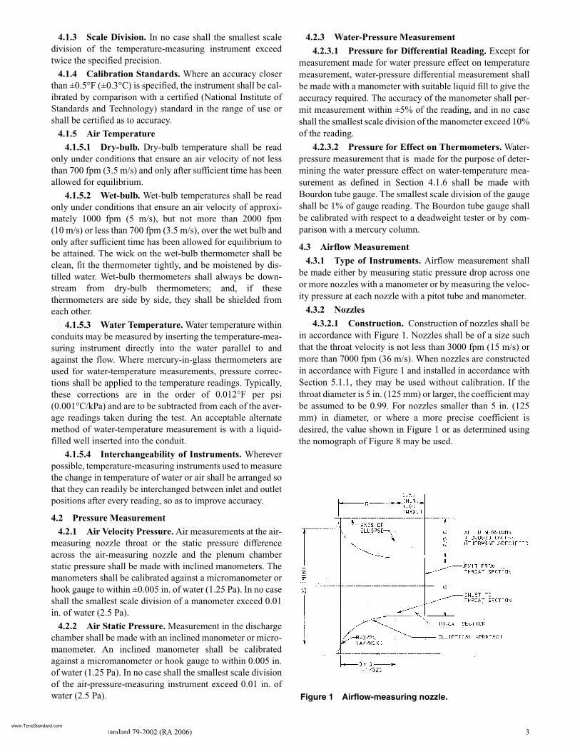
5.2.1.1 General. See Figure 3a. Install the fan coil undertest in the test room and the source of cooling and/or heatingconnected thereto.
5.2.1.2 Connect Airflow- and Temperature-Measur-ing Apparatus. Connect this apparatus to the discharge of thefan coil under test.
5.2.1.3 Install an Air-Sampling Psychrometer. Installan air-sampling psychrometer to sample air entering thereturn air inlet openings. Construct the air-sampling tube soas to provide not less than six air-sampling stations equallydistributed across the area of the air inlet openings of the fancoil under test and not more than 6 in. (150 mm) in front of theopening.
5.2.2 Loop Air-Enthalpy Test Method Arrangement5.2.2.1 General. See Figure 3b. Install the fan coil
under test in the appropriate test room, and connect the cool-ing and/or heating source thereto.
5.2.2.2 Connect Airflow- and Temperature-Measur-ing Apparatus. Connect this apparatus to the discharge of thefan coil under test.
5.2.2.3 Connect the Discharge of the ReconditioningEquipment. Connect the discharge of reconditioning equip-ment (Section 5.2.2.2) fan through ductwork to the intake ofthe fan coil under test. Make the inlet connection so as not tointerfere with the normal functioning of the fan coil undertest. The reconditioning equipment shall contain a means forextracting or adding heat to the air and adding moisture to theair, at the same rate as heat is added to and heat and moistureare extracted from the air when it passes through the test unit.The equipment fan shall be capable of moving air through theairflow- and temperature-measuring apparatus and recondi-tioning equipment at a rate that will maintain a maximum of0.005 in. of water (1.25 Pa) static pressure differentialbetween the inlet and outlet of the fan coil under test.
5.2.2.4 Install a Manometer. Install a manometer withpressure taps test at the inlet and outlet connections of the fancoil under test. It is recommended that the pressure taps con-sist of nominal 1/4 in. (6 mm) diameter pipe nipples solderedto the outer plenum surface and centered over 0.040 in.(1 mm) diameter holes through the plenum. The edges of theseholes shall be free of burrs and other surface irregularities.
5.2.2.5 Install an Air-Sampling Psychrometer. Installan air-sampling psychrometer in the duct as close as possibleto the inlet of the fan coil under test. Arrange the constructionof the sampling tube so as to provide the number and distri-bution of air-sampling stations sufficient to obtain an accuratetotal air sample.
Figure 3c Calorimeter air-enthalpy test methodarrangement.
Figure 3b Loop air-enthalpy test method arrangement.
Figure 3a Tunnel air-enthalpy test methodarrangement.
www.TeraStandard.com
--`,````,`,,````,,``,,``,`,`,,-`-`,,`,,`,`,,`---

ANSI/ASHRAE Standard 79-2002 (RA 2006) 7
5.2.2.6 Seal the Loop Ductwork and ReconditioningEquipment. Seal this equipment so that air leakage at placesthat would influence capacity measurements does not exceed1.0% of the test airflow rate.
5.2.2.7 Maintain the Dry-Bulb Temperature. Main-tain the dry-bulb temperature of the air surrounding the fancoil under test within 5°F (3°C) of the desired test inlet dry-bulb temperature.
5.2.3 Calorimeter Air-Enthalpy Test Method Arran-gement
5.2.3.1 General. See Figure 3c. Install the fan coilunder test in appropriate test room, and connect the source ofcooling and/or heating thereto.
5.2.3.2 Connect Airflow- and Temperature-Measur-ing Apparatus. Connect this apparatus to the discharge of thefan coil under test.
5.2.3.3 Install Air-Sampling Psychrometers. Installair-sampling psychrometers with sampling stations in front ofthe return air inlet opening of the fan coil under test and in frontof the air inlet opening of the calorimeter enclosure. Constructthe air-sampling tube so as to provide not less than six air-sam-pling stations equally distributed across the area of the air inletopenings of the fan coil under test and calorimeter enclosureand not more than 6 in. (150 mm) in front of opening.
5.2.3.4 Calorimeter Enclosure. Place an enclosure asdescribed herein over the fan coil under test. This enclosuremay be constructed of any suitable material, but it shall beessentially airtight. It shall be large enough to permit inlet airto circulate freely between the fan coil under test and theenclosure, and in no case shall the enclosure be closer than6 in. (150 mm) to any of the fan coil under test. Locate theinlet to the enclosure remotely from the inlet of the fan coilunder test so as to cause circulation throughout the entireenclosed space. The inlet opening size shall be of a size tokeep the air velocity through the opening at less than 500 fpm(2.5 m/s). Enclosure shall be insulated so as to limit heat trans-fer to 2% of the test unit capacity.
5.2.3.5 Install the Manometer. Install the manometerwith connections to the plenum of the fan coil under test andto the calorimeter enclosure. The airflow- and temperature-measuring apparatus fan shall maintain an airflow such thatzero static pressure differential will exist between the test unitoutlet and interior of calorimeter enclosure.
5.3 Reconditioning Equipment5.3.1 Air-Conditioning and Heating Equipment. This
equipment shall be provided for the test room to maintain thequality of the air entering the fan coil under test within the tol-erances prescribed in Section 8.6.
5.4 Water-Measuring Apparatus5.4.1 Liquid Quantity Measurement. Rate may be
determined by a liquid quantity meter measuring eitherweight or volume of the following types.
1. Calibrated Tank. Provide a calibrated tank having suffi-cient capacity to accumulate the flow for at least twominutes and so located that the water leaving the fan coilunder test can be diverted into it.
2. A liquid flowmeter may be used that will measure waterflow rate through the test unit coil.
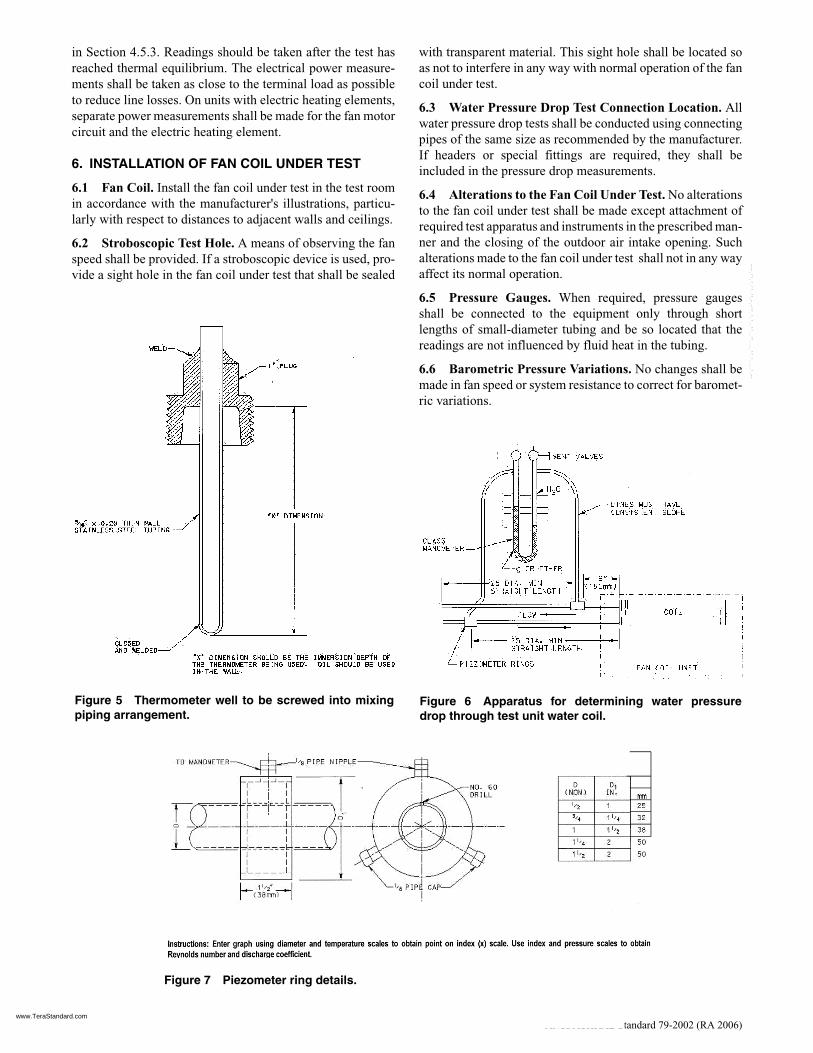
5.4.2 Temperature-Measuring Instruments. Theseinstruments shall be placed so as to measure accurately thetemperature of water entering and leaving the coil of the fancoil under test. The water lines shall be insulated at leastbetween the fan coil under test and the water temperature-measuring instruments and 6 in. (150 mm) beyond the watertemperature-measuring instruments. To minimize possibletemperature stratification, mixers shall be inserted in the inletand the outlet water lines upstream from the temperature-measuring instruments. Figure 4 shows suggested pipingarrangements to ensure thorough mixing. Figure 4 also showsa suggested configuration of the alternate temperature-mea-surement arrangement employing a liquid-filled well.Figure 5 shows the thermometer well to be screwed into mix-ing piping arrangement of Figure 4.
5.4.3 Water Pressure Drop. Water pressure drop throughthe coil of the fan coil under test from inlet to outlet shall bemeasured. Figure 6 shows the suggested test apparatus. Thepiezometer rings shall be located in accordance with thedimensions shown in Figure 6 and constructed as shown inFigure 7. Pressure taps may be used in lieu of piezometerrings.
5.5 Electrical Power-Measurement5.5.1 Test Procedure. Electrical measurements shall be
made with instruments conforming to the requirements listed
Figure 4 Suggested methods for ensuring thoroughmixing.
www.TeraStandard.com
--`,````,`,,````,,``,,``,`,`,,-`-`,,`,,`,`,,`---
8 ANSI/ASHRAE Standard 79-2002 (RA 2006)
in Section 4.5.3. Readings should be taken after the test hasreached thermal equilibrium. The electrical power measure-ments shall be taken as close to the terminal load as possibleto reduce line losses. On units with electric heating elements,separate power measurements shall be made for the fan motorcircuit and the electric heating element.
6. INSTALLATION OF FAN COIL UNDER TEST
6.1 Fan Coil. Install the fan coil under test in the test roomin accordance with the manufacturer's illustrations, particu-larly with respect to distances to adjacent walls and ceilings.
6.2 Stroboscopic Test Hole. A means of observing the fanspeed shall be provided. If a stroboscopic device is used, pro-vide a sight hole in the fan coil under test that shall be sealed
with transparent material. This sight hole shall be located soas not to interfere in any way with normal operation of the fancoil under test.
6.3 Water Pressure Drop Test Connection Location. Allwater pressure drop tests shall be conducted using connectingpipes of the same size as recommended by the manufacturer.If headers or special fittings are required, they shall beincluded in the pressure drop measurements.
6.4 Alterations to the Fan Coil Under Test. No alterationsto the fan coil under test shall be made except attachment ofrequired test apparatus and instruments in the prescribed man-ner and the closing of the outdoor air intake opening. Suchalterations made to the fan coil under test shall not in any wayaffect its normal operation.
6.5 Pressure Gauges. When required, pressure gaugesshall be connected to the equipment only through shortlengths of small-diameter tubing and be so located that thereadings are not influenced by fluid heat in the tubing.
6.6 Barometric Pressure Variations. No changes shall bemade in fan speed or system resistance to correct for baromet-ric variations.
Figure 5 Thermometer well to be screwed into mixingpiping arrangement.
Figure 6 Apparatus for determining water pressuredrop through test unit water coil.
Figure 7 Piezometer ring details.
www.TeraStandard.com
--`,````,`,,````,,``,,``,`,`,,-`-`,,`,,`,`,,`---
ANSI/ASHRAE Standard 79-2002 (RA 2006) 9
7. TEST METHODS AND PROCEDURES
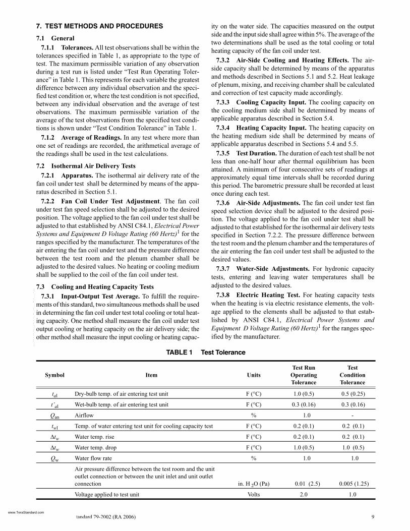
7.1 General7.1.1 Tolerances. All test observations shall be within the
tolerances specified in Table 1, as appropriate to the type oftest. The maximum permissible variation of any observationduring a test run is listed under “Test Run Operating Toler-ance” in Table 1. This represents for each variable the greatestdifference between any individual observation and the speci-fied test condition or, where the test condition is not specified,between any individual observation and the average of testobservations. The maximum permissible variation of theaverage of the test observations from the specified test condi-tions is shown under “Test Condition Tolerance” in Table 1.
7.1.2 Average of Readings. In any test where more thanone set of readings are recorded, the arithmetical average ofthe readings shall be used in the test calculations.
7.2 Isothermal Air Delivery Tests7.2.1 Apparatus. The isothermal air delivery rate of the
fan coil under test shall be determined by means of the appa-ratus described in Section 5.1.
7.2.2 Fan Coil Under Test Adjustment. The fan coilunder test fan speed selection shall be adjusted to the desiredposition. The voltage applied to the fan coil under test shall beadjusted to that established by ANSI C84.1, Electrical PowerSystems and Equipment Ð Voltage Rating (60 Hertz)1 for theranges specified by the manufacturer. The temperatures of theair entering the fan coil under test and the pressure differencebetween the test room and the plenum chamber shall beadjusted to the desired values. No heating or cooling mediumshall be supplied to the coil of the fan coil under test.
7.3 Cooling and Heating Capacity Tests7.3.1 Input-Output Test Average. To fulfill the require-
ments of this standard, two simultaneous methods shall be usedin determining the fan coil under test total cooling or total heat-ing capacity. One method shall measure the fan coil under testoutput cooling or heating capacity on the air delivery side; theother method shall measure the input cooling or heating capac-
ity on the water side. The capacities measured on the outputside and the input side shall agree within 5%. The average of thetwo determinations shall be used as the total cooling or totalheating capacity of the fan coil under test.
7.3.2 Air-Side Cooling and Heating Effects. The air-side capacity shall be determined by means of the apparatusand methods described in Sections 5.1 and 5.2. Heat leakageof plenum, mixing, and receiving chamber shall be calculatedand correction of test capacity made accordingly.
7.3.3 Cooling Capacity Input. The cooling capacity onthe cooling medium side shall be determined by means ofapplicable apparatus described in Section 5.4.
7.3.4 Heating Capacity Input. The heating capacity onthe heating medium side shall be determined by means ofapplicable apparatus described in Sections 5.4 and 5.5.
7.3.5 Test Duration. The duration of each test shall be notless than one-half hour after thermal equilibrium has beenattained. A minimum of four consecutive sets of readings atapproximately equal time intervals shall be recorded duringthis period. The barometric pressure shall be recorded at leastonce during each test.
7.3.6 Air-Side Adjustments. The fan coil under test fanspeed selection device shall be adjusted to the desired posi-tion. The voltage applied to the fan coil under test shall beadjusted to that established for the isothermal air delivery testsspecified in Section 7.2.2. The pressure difference betweenthe test room and the plenum chamber and the temperatures ofthe air entering the fan coil under test shall be adjusted to thedesired values.
7.3.7 Water-Side Adjustments. For hydronic capacitytests, entering and leaving water temperatures shall beadjusted to the desired values.
7.3.8 Electric Heating Test. For heating capacity testswhen the heating is via electric resistance elements, the volt-age applied to the elements shall be adjusted to that estab-lished by ANSI C84.1, Electrical Power Systems andEquipment Ð Voltage Rating (60 Hertz)1 for the ranges spec-ified by the manufacturer.
TABLE 1 Test Tolerance
Symbol Item UnitsTest Run
OperatingTolerance
Test ConditionTolerance
tal Dry-bulb temp. of air entering test unit F (°C) 1.0 (0.5) 0.5 (0.25)
t’al Wet-bulb temp. of air entering test unit F (°C) 0.3 (0.16) 0.3 (0.16)
Qan Airflow % 1.0 -
twl Temp. of water entering test unit for cooling capacity test F (°C) 0.2 (0.1) 0.2 (0.1)
∆tw Water temp. rise F (°C) 0.2 (0.1) 0.2 (0.1)
∆tw Water temp. drop F (°C) 1.0 (0.5) 1.0 (0.5)
Qw Water flow rate % 1.0 1.0
Air pressure difference between the test room and the unit outlet connection or between the unit inlet and unit outlet connection in. H 2O (Pa) 0.01 (2.5) 0.005 (1.25)
Voltage applied to test unit Volts 2.0 1.0
www.TeraStandard.com
--`,````,`,,````,,``,,``,`,`,,-`-`,,`,,`,`,,`---

10 ANSI/ASHRAE Standard 79-2002 (RA 2006)
8. CALCULATIONS
8.1 Isothermal Air Delivery TestsNote: See Section 8.5 for symbol designations.
8.1.1 The specific volume of the air-vapor mixture at thenozzle shall be calculated as follows:
8.1.1.1 The humidity ratio shall be calculated as follows:
8.1.1.2 The specific volume shall be calculated as follows:
8.1.2 The volume flow rate through a single nozzle shallbe calculated as follows:
8.1.3 The total airflow rate through multiple nozzles is thesum of the flow rates for each nozzle used.
8.1.4 The specific volume of the air-vapor mixture enter-ing the fan coil under test shall be calculated as follows:
8.1.5 The air delivery rate for the fan coil under test shallbe calculated as follows:
8.1.6 To correct the air delivery rate to standard airflow,the following equation shall be used:
8.2 Cooling and Heating Capacity Tests8.2.1 Airflow Calculations
8.2.1.1 The specific volume of the air-vapor mixture atthe nozzle shall be calculated as follows:
Note: See Sections 8.1.1.1 and 8.1.1.2 for equations for Wnand vn.
8.2.1.2 The mass flow rate of air in lb/h (kg/s) through asingle nozzle shall be calculated as follows:
8.2.1.3 The total mass flow rate of air through multiplenozzles is the sum of the flow rates for each nozzle used.
8.2.2 Heat Leakage Calculation8.2.2.1 The heat leakage for the plenum, receiving, and
mixing chambers is calculated as the product of square feet(square meters) of total exposed area of the chambers and theheat transmission coefficient corresponding to the construc-tion and the insulation used and the temperature difference.The coefficient of heat transmission may be determined bytesting or calculation. The value of ta3, the dry-bulb tempera-ture of the air surrounding the plenum, mixing, and receivingchambers, used in this calculation, shall be the average of themeasurements at not less than two locations.
8.2.2.2 Heat leakage shall be calculated as follows:Cooling Capacity Tests
Heating Capacity Tests
Figure 8 Determination of nozzle discharge coefficient.
vn′ v1
1 W1+---------------- 29.92
Pb pv 13.62⁄( )+----------------------------------------
460 tan+
460 ta1+----------------------××=
or29.92vn
Pn 1 Wn+( )----------------------------=
v1
1 W1+---------------- 101
Pb pv+-----------------×
273 tan+
273 ta1+----------------------×
⎝ ⎠⎛ ⎞=
or101vn
Pn 1 Wn+( )----------------------------⎝ ⎠⎛ ⎞=
W1
1093 0.556ta1–( )Ws1 0.240 ta1 ta1–( )–
1093 0.444ta1 ta1′–+
--------------------------------------------------------------------------------------------------=
2.5 106× 3155ta1
′–( )Ws1 1005 ta1 ta1′–( )–
2.5 106
1035ta1+× 4190ta1′–
---------------------------------------------------------------------------------------------------------⎝ ⎠⎜ ⎟⎛ ⎞
=
Wn
1093 0.556ta2′–( )Wsn 0.240 ta2 ta2
′–( )–
1093 0.444ta2 ta2′–+
--------------------------------------------------------------------------------------------------=
2.5 106× 3155ta2
′–( )Wsn 1005 ta2 ta2′–( )–
2.5 106
1035ta2+× 4190ta2′–
---------------------------------------------------------------------------------------------------------⎝ ⎠⎜ ⎟⎛ ⎞
=
v1
53.352 460 ta1+( )70.726Pb
-------------------------------------------- 1 1.6078 W1+( )=
0.287 273 ta1+( )Pb
----------------------------------------- 1 1.6078 W1+( )⎝ ⎠⎛ ⎞=
vn
53.352 460 tan+( )70.726Pn
-------------------------------------------- 1 1.6078 Wn+( )=
0.287 273 tan+( )Pn
----------------------------------------- 1 1.6078 Wn+( )⎝ ⎠⎛ ⎞=
Qan 1096AnCn pvvn′( )
0.5=
1414AnCn pvvn′( )
0.5( )=
v1′ v1
1 W1+----------------=
Qa Qan
v1′( )
vn′( )
----------=
Qs
Qa
0.075 v1′( )
-----------------------Qa
1.2 v1′( )
-----------------⎝ ⎠⎜ ⎟⎛ ⎞
= =
vn′ 29.92vn
Pn 1 Wn+( )----------------------------
101vn
Pn 1 Wn+( )----------------------------⎝ ⎠⎛ ⎞= =
wa 4.5 Qs 0.0012 Qs×( )= =
qk AkUk ta3 ta2–( )=
qk AkUk ta2 ta3–( )=
www.TeraStandard.com
--`,````,`,,````,,``,,``,`,`,,-`-`,,`,,`,`,,`---

ANSI/ASHRAE Standard 79-2002 (RA 2006) 11
8.2.3 Fan Motor Heat Calculation. The heat of the elec-tric power input to the fan motor shall be calculated as fol-lows:
8.2.4 Air-Side Cooling Capacity Calculation 8.2.4.1 The air-side total cooling capacity shall be cal-
culated as follows:
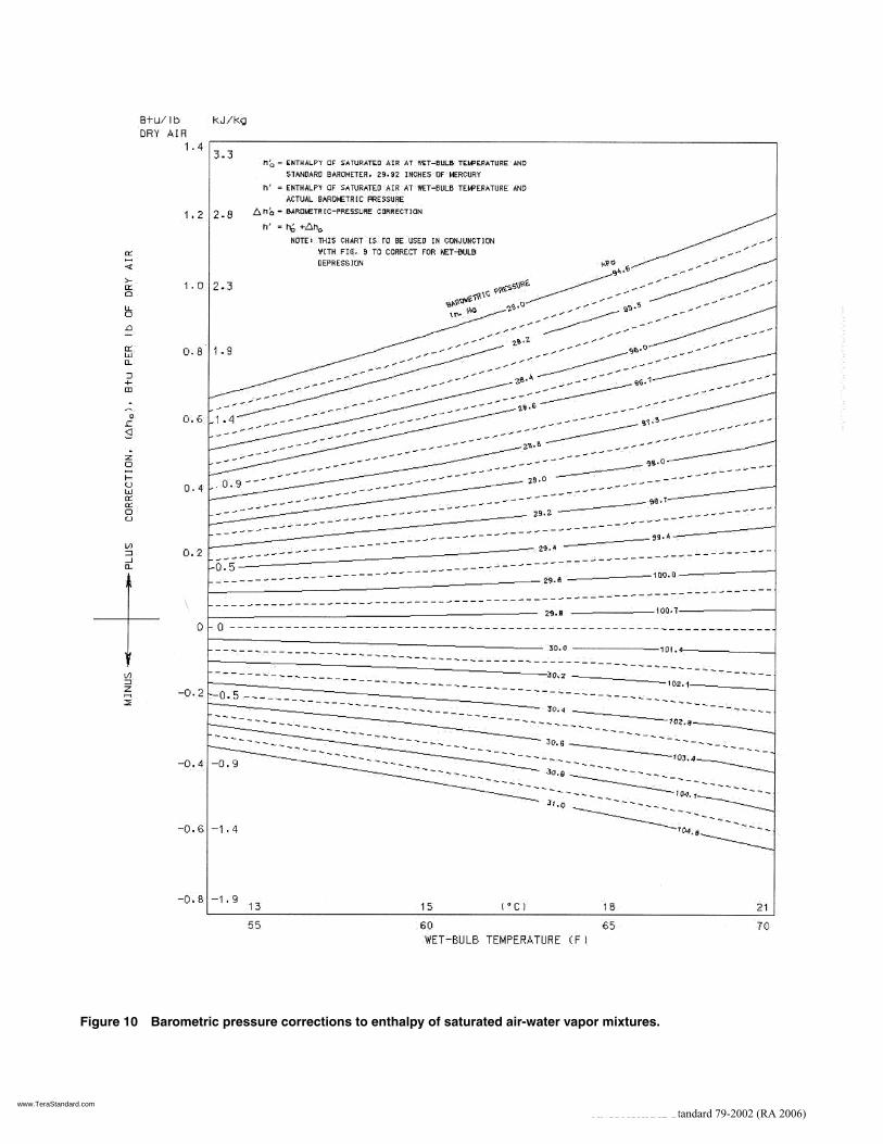
The enthalpy of the air-water vapor mixture shall becorrected for the barometric pressure and wet-bulb depression(see Figures 9 and 10 and reference Section 9.4).
8.2.4.2 The air-side sensible cooling capacity shall becalculated as follows:
8.2.5 Air-Side Heating Capacity Calculation. The air-side heating capacity shall be calculated as follows:
8.2.6 Water Flow Calculation. Where the water flow rateis measured in volume rather than mass, the calculation for theconversion to mass flow rate units of measure shall be as fol-lows:
8.2.7 Water-Side Cooling Capacity Calculation. Thetotal water-side cooling capacity shall be calculated as follows:
8.2.8 Water-Side Heating Capacity Calculation. Thetotal water-side heating capacity shall be calculated as follows:
8.2.9 Electric Element Heating Capacity Calculation.The element-side heating capacity shall be calculated as follows:
8.3 Average Capacities and Heat Balance Calculations8.3.1 The average cooling capacities of the air and water
side shall be calculated as follows:
The heat balance between the air- and water-side capac-ities shall be calculated as follows:
The heat balance shall fall within the limits specified inSection 7.3.1.
8.3.2 The average heating capacities shall be calculated asfollows:
8.3.2.1 Water Coils
The heat balance between the air- and water-side capac-ities shall be calculated as follows:
qe 3.41 Pe Pe( )= =
qtca
wa ha1 ha2–( ) W1 Wn–( ) ta2′ 32–( )–[ ]
1 Wn+( )----------------------------------------------------------------------------------------------- qk+=
qtca
1000wa ha1 ha2–( ) W1 Wn–( ) 4.2ta2′( )–[ ]
1 Wn+( )------------------------------------------------------------------------------------------------------- qk+=
⎝ ⎠⎜ ⎟⎛ ⎞
Figure 9 Wet-bulb depression corrections to enthalpy of air-water vapor mixture.
qs
wacpa ta1 ta2–( )1 Wn+( )
--------------------------------------- qk+=
cpa 0.24 0.444 Wn+ 1.0056 1.86 Wn+( )= =
qtha
wacpa ta2 ta1–( )1 Wn+( )
--------------------------------------- qk+=
ww 8.02ρwQw
ρwQw( )1000
-------------------⎝ ⎠⎛ ⎞= =
qtcw wwcpw tw2 tw1–( ) 1000wwcpw tw2 tw1–( )( )= =
qthw wwcpw tw1 tw2–( ) 1000wwcpw tw1 tw2–( )( )= =
qee 3.41 Pee× Pee( )= =
qc 0.5 qtca qtcw qe–+( )=
HB100 qtca qtcw qe+–( )
qc----------------------------------------------------=
qh 0.5 qtha qthw qe+ +( )=
HB100 qtha qthw– qe–( )
qh----------------------------------------------------=
www.TeraStandard.com
--`,````,`,,````,,``,,``,`,`,,-`-`,,`,,`,`,,`---
12 ANSI/ASHRAE Standard 79-2002 (RA 2006)
Figure 10 Barometric pressure corrections to enthalpy of saturated air-water vapor mixtures.
www.TeraStandard.com
--`,````,`,,````,,``,,``,`,`,,-`-`,,`,,`,`,,`---

ANSI/ASHRAE Standard 79-2002 (RA 2006) 13
8.3.2.2 Electric Coils
The heat balance between the air and electric coil capac-ities shall be calculated as follows:
8.4 Water Pressure Drop TestsThe test measurement of water pressure drop between
piezometer rings or pressure taps shall be reduced by the waterpressure drop of the total length of pipe between the piezom-eter rings or pressure taps and the test unit coil. This pipingloss shall be determined by calibration of the test apparatus.
8.5 SymbolsAk = area, exposed walls of plenum, mixing, and
receiving chambers, ft2 (m2)
An = area, nozzle throat, ft2 (m2)
Cn = coefficient of discharge, nozzle
cpa = specific heat of air, Btu/lb·°F (kJ/kg °C) of dry air
cpw = specific heat of water, Btu/lb·°F (kJ/kg °C)
ha1 = enthalpy, air entering unit, Btu/lb (kJ/kg)
ha2 = enthalpy, air leaving unit, Btu/lb (kJ/kg)
HB = heat balance tolerance, percent
Pb = pressure, barometric, in. Hg (kPa)
Pe = power input to fan motor, W
Pee = power input to electrical resistance element, W
Pn = pressure, at nozzle throat, in. Hg absolute (kPa)
pv = velocity pressure at nozzle throat or static pressuredifference across nozzle, in. H2O (Pa)
qc = average cooling capacity of air and water side, Btu/h (W)
qe = equivalent heat input due to fan motor, Btu/h (W)
qee = equivalent heat input to electrical resistance element,Btu/h (W)
qh = average heating capacity of air and water (or electricelement) sides, Btu/h (W)
qk = heat leakage of plenum and/or ductwork ahead oftemperature-measuring apparatus, Btu/h (W)
qs = sensible capacity Btu/h (W)
qtca = total cooling capacity, air side, Btu/h (W)
qtha = total heating capacity, air side, Btu/h (W)
qtcw = total cooling capacity, water side, Btu/h (W)
qthw = total heating capacity, water side, Btu/h (W)
Qan = airflow, measured, cfm (L/s)
Qa = airflow at test unit, cfm (L/s)
Qs = airflow, standard air, cfm (L/s)
Qw = water flow, gpm (L/s)
tal = temperature, air entering unit, dry-bulb, °F (°C)
t’a1 = temperature, air entering unit, wet-bulb, °F (°C)
ta2 = temperature, air leaving unit, dry-bulb, °F (°C)
t’a2 = temperature, air leaving unit, wet-bulb, °F (°C)
ta3 = temperature, ambient air surrounding plenum andmixing chamber, dry-bulb, °F (°C)
tw1 = temperature, water entering unit, °F (°C)tw2 = temperature, water leaving unit, °F (°C)Uk = coefficient, heat leakage, Btu/h⋅ft2⋅°F (W/m2⋅°C)v1 = specific volume of air, entering unit, ft3/lb (m3/kg)vn = specific volume of air at dry- and wet-bulb
temperature conditions existing at nozzle but atstandard barometric pressure, ft3/lb (m3/kg)
v’n = specific volume of air at nozzle, ft3/lb (m3/kg) of air-water vapor mixture
wa = mass flow rate of air, lb/h (kg/s)ww = mass flow rate of water, lb/h (kg/s)W1 = humidity ratio, at inlet, lbs water vapor per lb (kg/kg)
dry airWn = humidity ratio, at nozzle, lbs water vapor per lb
(kg/kg) dry airWs1 = humidity ratio at saturation at wet-bulb temperature
at inlet, lbs water vapor per lb dry air (kg/kg)Wsn = humidity ratio at saturation at wet-bulb temperature
at nozzle, lbs water vapor per lb dry air (kg/kg)ρw = density, of water, lb/ft3 (kg/m3)
8.6 Test Tolerances8.6.1 All test observations shall be within the tolerances
specified in Table 1, as appropriate to the test methods. SeeSection 7.1.1.
8.6.2 The maximum permissible variation of any observa-tion during the capacity test is listed under “Test OperatingTolerance” in the table. This represents the greatest permissi-ble difference between maximum and minimum instrumentobservations during the test. When expressed in percentage,the maximum allowable variation is the specified percentageof the arithmetical average of the observations.
8.6.3 The maximum permissible deviations of the aver-ages of the test observations from the standard or desired testconditions are shown in Table 1 under “Test Condition Toler-ance.”
8.6.4 Variations and/or deviations greater than those pre-scribed shall invalidate the test.
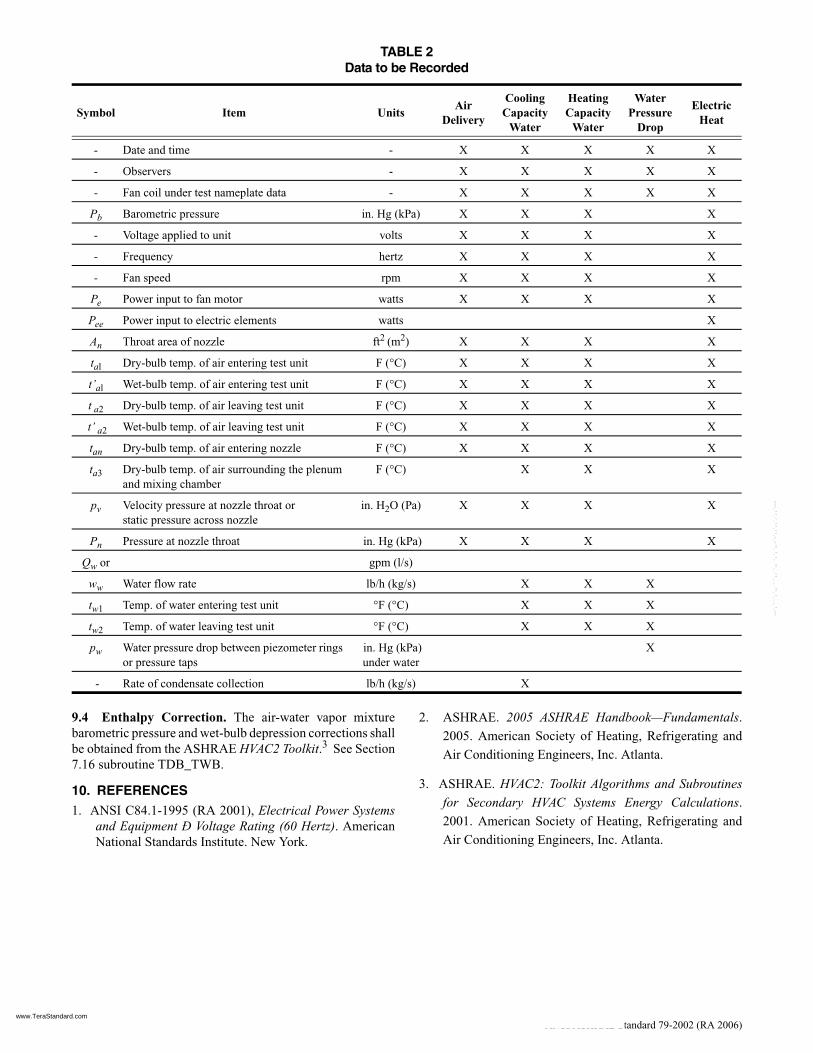
8.7 Data To Be Recorded. Table 2 shows, generally, thedata to be recorded during a test. Items indicated by an “X”are required for the test being conducted.
9. REFERENCE PROPERTIES AND DATA
9.1 Thermodynamic Properties of Air. The thermo-dynamic properties of air-water vapor mixture shall beobtained from the 2005 ASHRAE Handbook—Fundamen-tals.2
9.2 Thermodynamic Properties of Water. The thermody-namic properties of water shall be obtained from the 2005ASHRAE Handbook—Fundamentals.2
9.3 Heat Transmission Coefficients. The heat transmis-sion coefficients for various materials shall be obtained fromthe 2005 ASHRAE Handbook—Fundamentals.2
qh 0.5 qtha qee qe+ +( )=
HB100 qtha qee– qe–( )
qh-------------------------------------------------=
www.TeraStandard.com
--`,````,`,,````,,``,,``,`,`,,-`-`,,`,,`,`,,`---
14 ANSI/ASHRAE Standard 79-2002 (RA 2006)
9.4 Enthalpy Correction. The air-water vapor mixturebarometric pressure and wet-bulb depression corrections shallbe obtained from the ASHRAE HVAC2 Toolkit.3 See Section7.16 subroutine TDB_TWB.
10. REFERENCES1. ANSI C84.1-1995 (RA 2001), Electrical Power Systems
and Equipment Ð Voltage Rating (60 Hertz). AmericanNational Standards Institute. New York.
2. ASHRAE. 2005 ASHRAE Handbook—Fundamentals.2005. American Society of Heating, Refrigerating andAir Conditioning Engineers, Inc. Atlanta.
3. ASHRAE. HVAC2: Toolkit Algorithms and Subroutines
for Secondary HVAC Systems Energy Calculations.2001. American Society of Heating, Refrigerating andAir Conditioning Engineers, Inc. Atlanta.
TABLE 2 Data to be Recorded
Symbol Item UnitsAir
Delivery
Cooling Capacity
Water
HeatingCapacity
Water
Water Pressure
Drop
ElectricHeat
- Date and time - X X X X X
- Observers - X X X X X
- Fan coil under test nameplate data - X X X X X
Pb Barometric pressure in. Hg (kPa) X X X X
- Voltage applied to unit volts X X X X
- Frequency hertz X X X X
- Fan speed rpm X X X X
Pe Power input to fan motor watts X X X X
Pee Power input to electric elements watts X
An Throat area of nozzle ft2 (m2) X X X X
tal Dry-bulb temp. of air entering test unit F (°C) X X X X
t’al Wet-bulb temp. of air entering test unit F (°C) X X X X
t a2 Dry-bulb temp. of air leaving test unit F (°C) X X X X
t’ a2 Wet-bulb temp. of air leaving test unit F (°C) X X X X
tan Dry-bulb temp. of air entering nozzle F (°C) X X X X
ta3 Dry-bulb temp. of air surrounding the plenum and mixing chamber
F (°C) X X X
pv Velocity pressure at nozzle throat orstatic pressure across nozzle
in. H2O (Pa) X X X X
Pn Pressure at nozzle throat in. Hg (kPa) X X X X
Qw or gpm (l/s)
ww Water flow rate lb/h (kg/s) X X X
tw1 Temp. of water entering test unit °F (°C) X X X
tw2 Temp. of water leaving test unit °F (°C) X X X
pw Water pressure drop between piezometer rings or pressure taps
in. Hg (kPa)under water
X
- Rate of condensate collection lb/h (kg/s) X
www.TeraStandard.com
--`,````,`,,````,,``,,``,`,`,,-`-`,,`,,`,`,,`---

POLICY STATEMENT DEFINING ASHRAE’S CONCERNFOR THE ENVIRONMENTAL IMPACT OF ITS ACTIVITIES
ASHRAE is concerned with the impact of its members’ activities on both the indoor and outdoor environment. ASHRAE’smembers will strive to minimize any possible deleterious effect on the indoor and outdoor environment of the systems andcomponents in their responsibility while maximizing the beneficial effects these systems provide, consistent with acceptedstandards and the practical state of the art.
ASHRAE’s short-range goal is to ensure that the systems and components within its scope do not impact the indoor andoutdoor environment to a greater extent than specified by the standards and guidelines as established by itself and otherresponsible bodies.
As an ongoing goal, ASHRAE will, through its Standards Committee and extensive technical committee structure,continue to generate up-to-date standards and guidelines where appropriate and adopt, recommend, and promote those newand revised standards developed by other responsible organizations.
Through its Handbook, appropriate chapters will contain up-to-date standards and design considerations as the material issystematically revised.
ASHRAE will take the lead with respect to dissemination of environmental information of its primary interest and will seekout and disseminate information from other responsible organizations that is pertinent, as guides to updating standards andguidelines.
The effects of the design and selection of equipment and systems will be considered within the scope of the system’sintended use and expected misuse. The disposal of hazardous materials, if any, will also be considered.
ASHRAE’s primary concern for environmental impact will be at the site where equipment within ASHRAE’s scopeoperates. However, energy source selection and the possible environmental impact due to the energy source and energytransportation will be considered where possible. Recommendations concerning energy source selection should be made byits members.
www.TeraStandard.com
--`,````,`,,````,,``,,``,`,`,,-`-`,,`,,`,`,,`---

86210PC 2/06
www.TeraStandard.com
--`,````,`,,````,,``,,``,`,`,,-`-`,,`,,`,`,,`---