Embed Size (px)
Citation preview
183
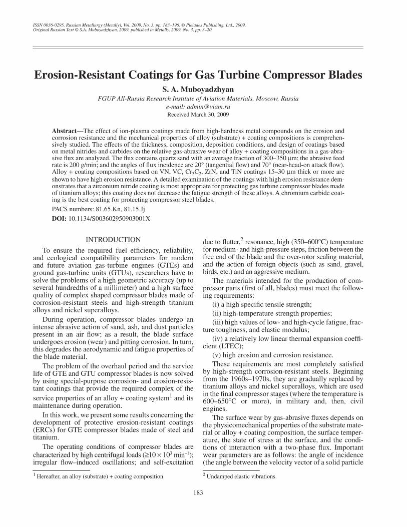
ISSN 0036-0295, Russian Metallurgy (Metally), Vol. 2009, No. 3, pp. 183–196. © Pleiades Publishing, Ltd., 2009.Original Russian Text © S.A. Muboyadzhyan, 2009, published in Metally, 2009, No. 3, pp. 3–20.
INTRODUCTION
To ensure the required fuel efficiency, reliability,and ecological compatibility parameters for modernand future aviation gas-turbine engines (GTEs) andground gas-turbine units (GTUs), researchers have tosolve the problems of a high geometric accuracy (up toseveral hundredths of a millimeter) and a high surfacequality of complex shaped compressor blades made ofcorrosion-resistant steels and high-strength titaniumalloys and nickel superalloys.
During operation, compressor blades undergo anintense abrasive action of sand, ash, and dust particlespresent in an air flow; as a result, the blade surfaceundergoes erosion (wear) and pitting corrosion. In turn,this degrades the aerodynamic and fatigue properties ofthe blade material.
The problem of the overhaul period and the servicelife of GTE and GTU compressor blades is now solvedby using special-purpose corrosion- and erosion-resis-tant coatings that provide the required complex of theservice properties of an alloy + coating system
1
and itsmaintenance during operation.
In this work, we present some results concerning thedevelopment of protective erosion-resistant coatings(ERCs) for GTE compressor blades made of steel andtitanium.
The operating conditions of compressor blades arecharacterized by high centrifugal loads (
≥
10
×
10
3
min
–1
);irregular flow–induced oscillations; and self-excitation
1
Hereafter, an alloy (substrate) + coating composition.
due to flutter,
2
resonance, high (350–600
°
C) temperaturefor medium- and high-pressure steps, friction between thefree end of the blade and the over-rotor sealing material,and the action of foreign objects (such as sand, gravel,birds, etc.) and an aggressive medium.
The materials intended for the production of com-pressor parts (first of all, blades) must meet the follow-ing requirements:
(i) a high specific tensile strength;(ii) high-temperature strength properties;(iii) high values of low- and high-cycle fatigue, frac-
ture toughness, and elastic modulus;(iv) a relatively low linear thermal expansion coeffi-
cient (LTEC);(v) high erosion and corrosion resistance.These requirements are most completely satisfied
by high-strength corrosion-resistant steels. Beginningfrom the 1960s–1970s, they are gradually replaced bytitanium alloys and nickel superalloys, which are usedin the final compressor stages (where the temperature is600–650
°
C or more), in military and, then, civilengines.
The surface wear by gas-abrasive fluxes depends onthe physicomechanical properties of the substrate mate-rial or alloy + coating composition, the surface temper-ature, the state of stress at the surface, and the condi-tions of interaction with a two-phase flux. Importantwear parameters are as follows: the angle of incidence(the angle between the velocity vector of a solid particle
2
Undamped elastic vibrations.
Erosion-Resistant Coatings for Gas Turbine Compressor Blades
S. A. Muboyadzhyan
FGUP All-Russia Research Institute of Aviation Materials, Moscow, Russiae-mail: [email protected]
Received March 30, 2009
Abstract
—The effect of ion-plasma coatings made from high-hardness metal compounds on the erosion andcorrosion resistance and the mechanical properties of alloy (substrate) + coating compositions is comprehen-sively studied. The effects of the thickness, composition, deposition conditions, and design of coatings basedon metal nitrides and carbides on the relative gas-abrasive wear of alloy + coating compositions in a gas-abra-sive flux are analyzed. The flux contains quartz sand with an average fraction of 300–350
µ
m; the abrasive feedrate is 200 g/min; and the angles of flux incidence are 20
°
(tangential flow) and 70
°
(near-head-on attack flow).Alloy + coating compositions based on VN, VC, Cr
3
C
2
, ZrN, and TiN coatings 15–30
µ
m thick or more areshown to have high erosion resistance. A detailed examination of the coatings with high erosion resistance dem-onstrates that a zirconium nitride coating is most appropriate for protecting gas turbine compressor blades madeof titanium alloys; this coating does not decrease the fatigue strength of these alloys. A chromium carbide coat-ing is the best coating for protecting compressor steel blades.
PACS numbers: 81.65.Kn, 81.15.Jj
DOI:
10.1134/S003602950903001X
184
RUSSIAN METALLURGY (METALLY)
Vol. 2009
No. 3
MUBOYADZHYAN
and the substrate surface); the particle velocity; the par-ticle shape and size; the physicomechanical propertiesof the abrasive material (hardness, impact toughness);the particle concentration in the flux; the flux tempera-ture, humidity, and pressure; the flux action time; andthe total number of abrasive particles per unit surface.The generalization of well-known results demonstratesthat GTE compressor blades undergo gas-abrasive wearpredominantly near the earth and that this wear ismainly caused by spherical (rounded) quartz sand par-ticles about 100
µ
m in size.
Gas-abrasive wear affects the characteristics of aGTE compressor. It is interesting that its intensitydepends on the number of GTE operation cycles andeventually causes a ~10% increase in the aerodynamiclosses and a multifold degradation of the compressoroperation efficiency because of both an increase in theradial gap and a change in the profile geometry and thesurface roughness of the compressor blade tip. Apartfrom a decrease in the mechanical properties of com-pressor blades, another challenging problem related togas-abrasive wear is a decrease in the gas-dynamic sta-bility margin of the compressor. Therefore, the devel-opment of allowed-wear standards is practically impor-tant for both the estimation of the service life and theformulation of requirements for protective coatings,flux cleaning devices, and wear diagnostics means.
Researchers at the All-Russia Research Institute ofAviation Materials have been studying and designingion-plasma coatings intended for the protection of steeland titanium GTE compressor blades against erosionfor years [1, 2].
As a result, they have designed and produced hard-ening coatings of zirconium nitride and chromium car-bide to protect titanium and steel GTE compressorblades, respectively, against erosion wear. These coat-ings are commercially deposited in ion-plasma MAPsetups, which are intended for the deposition of bothmetallic coatings and coatings based on metal nitridesand carbides by a high-energy plasmochemical methodwhen the corresponding reactive gas (N
2
, C
2
H
2
) isintroduced into a metallic plasma. In this work, westudy the properties of compressor steels and titaniumalloys covered with ion-plasma coatings.
EXPERIMENTAL
Ion-plasma ERCs were deposited by reactive iondeposition (high-energy plasmochemistry) in a labora-tory vacuum–plasma setup with an end-face Hallplasma accelerator (EHPA) and in vacuum–plasmaMAP-1M, MAP-2, and MAP-3 setups (MAP-2 is acomputer-assisted modification of MAP-1M, andMAP-3 differs from MAP-1M and MAP-2 in the pres-ence of an accelerator of gas ions to an energy of40 keV at an ion current of 40 mA.) Before deposition,the surfaces of the articles to be coated were degreasedin gasoline and acetone and, then, bombarded by either
argon ions and then coating-material ions or by onlycoating-material ions immediately before deposition ina working chamber.
The structures of the coatings were examined byVersamet-2 and GX-51 (Olympus) optical microscopesand DRON-3M and DRON-4 X-ray diffractometers.Phase analysis was performed using the PHAN X-raydiffraction pattern database. We recorded X-ray diffrac-tion patterns in both the angular range 20
°
–85
°
and inthe most important narrow range 10
°
–45
°
, where theexamined-layer depth was 5–17
µ
m. The elementalcomposition and microstructure of the coatings werestudied by electron-probe microanalysis and scanningelectron microscopy on a Superprobe JCMA-733device (JEOL, Japan). The elements to be detected byelectron-probe microanalysis ranged from B (
Z
= 5) toU (
Z
= 92). The analysis locality was 1
µ
m
2
, and theanalysis depth was ~1
µ
m.
The properties of the compositions with ion-plasmacoatings were studied on hot-strength test specimens(State Standard GOST 6130-71), long-term strengthtest specimens (GOST 10145), and endurance testspecimens (GOST 25.502). The corrosion resistance(salt corrosion) of samples was estimated using rapidcyclic tests according to OST 90212-77. The sampleswere held in a furnace in an air atmosphere at
T
= 500or 600
°
C for 1 h, cooled in air for 1–3 min, cooled in a3% NaCl solution, and stored in a damp exiccator for22 h. The protective properties of the samples with andwithout coatings were compared visually, with a binoc-ular MBS-2 microscope, and gravimetrically (byweighing them on a Sartorius analytical balance accu-rate to 10
–7
kg).
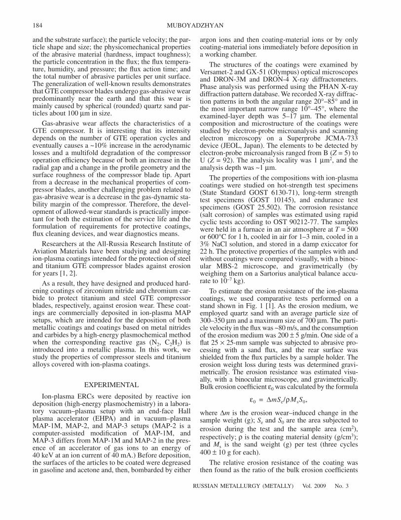
To estimate the erosion resistance of the ion-plasmacoatings, we used comparative tests performed on astand shown in Fig. 1 [1]. As the erosion medium, weemployed quartz sand with an average particle size of300–350
µ
m and a maximum size of 700
µ
m. The parti-cle velocity in the flux was ~80 m/s, and the consumptionof the erosion medium was 200
±
5 g/min. One side of aflat 25
×
25-mm sample was subjected to abrasive pro-cessing with a sand flux, and the rear surface wasshielded from the flux particles by a sample holder. Theerosion weight loss during tests was determined gravi-metrically. The erosion resistance was estimated visu-ally, with a binocular microscope, and gravimetrically.Bulk erosion coefficient
ε
0
was calculated by the formula
where
∆
m
is the erosion wear–induced change in thesample weight (g);
S
e
and
S
0
are the area subjected toerosion during the test and the sample area (cm
2
),respectively;
ρ
is the coating material density (g/cm
3
);and
M
s
is the sand weight (g) per test (three cycles400
±
10 g for each).
The relative erosion resistance of the coating wasthen found as the ratio of the bulk erosion coefficients
ε0 ∆mSe/ρMsS0,=
RUSSIAN METALLURGY (METALLY)
Vol. 2009
No. 3
EROSION-RESISTANT COATINGS FOR GAS TURBINE COMPRESSOR BLADES 185
of the base and coating materials (
ε
b.b
/
ε
b.c
), and the rel-ative erosion wear was calculated as
ε
b.c
/
ε
b.b
.
At fixed dust–air flux parameters, the erosion weardepended only on the type of alloy + coating composi-tion and the quantity of the consumed erosion medium.The tests were carried out at two angles of incidence
α
(i.e., the orientation of the sample plane with respect tothe axis of the incident flux), namely, 20
°
(tangentialflow) and 70
°
(near-head-on attack flow).
The basic diagram of the laboratory setup with anEHPA was considered in [3], and that of an MAP-1Msetup, in [4]. In MAP ion-plasma setups, the surface tobe coated is preliminarily cleaned in an argon-ion flowgenerated in an
E
×
H
accelerator with an anode layerat an argon ion energy of 1000–3000 eV, and the finalcleaning of the surface and its ion modification are per-formed in the plasma of the coating material. Theplasma of the coating material (pure metals, alloys) isgenerated in a high-current vacuum arc discharge (300–700 A) during the erosion of the material of the cylin-drical tube cathode in the setup by vacuum-arc cathodemicrospots, which were confined in a ring evaporationzone in the cathode by the magnetic field of an electro-magnetic microspot lock placed in the space of thecylindrical tube cathode. The energy of the particlesinteracting with the surface to be coated is controlledvia a negative potential (bias voltage) applied to the partto be coated from a controlled inverter power supply.The ion-current density from the plasma to the part tobe coated reaches 15–20 mA/cm
2
. MAP setups have adeposition zone height of up to 200 mm and 24 plane-tary rotation positions located at a diameter of 550 mmand provide the deposition of 100-
µ
m-thick coatingsonto 24–144 parts per working shift depending on thepart size. The cathode in these setups is made of anevaporated alloy and represents a tube with an outerdiameter of 180 mm, a wall thickness of 20 mm, and aheight of 340 mm. These dimensions ensure the volumeof the material to be evaporated (2300–2500 cm
3
) thatis sufficient for continuous setup operation for ~80 h ormore. The cathode is equipped with a reciprocatingmotion drive for its external surface to be evaporated.To deposit multilayer coatings, the tube cathode of aMAP setup was made of joined rings consisting of thereactive metals that form coating layers.
In contrast to MAP-1M and MAP-2 setups, aMAP-3 setup can also perform ion implantation modi-fication of a surface and ion-assisted deposition.
The high particle energies used for ion cleaning ofthe surface (up to 1400 eV) and the high ion-currentdensities in the plasma (15–20 mA/cm
2
) provide heat-ing and thermal activation of the surface of the treatedparts to the treatment temperature (200–1000
°
C) in 2–10 min depending on the part weight.
RESULTS AND DISCUSSION
To choose an ERC, we used a laboratory setup withan EHPA to deposit nitrides and carbides of various met-als (Ti, Zr, Cr, V, Mo, Nb, etc.) on flat 25
×
25
×
2-mmsamples made of compressor materials under the follow-ing conditions (which provide high-hardness coatings):the vacuum-arc current was 180–260 A, the arc voltagewas 26–31 V, the bias voltage was 250–300 V during ioncleaning and 150–160 V during ERC deposition, thedeposition rate was 0.4–0.8
µ
m/min for flat unmovablesamples placed at a distance of 230–240 mm from theend of the cathode, and the reactive gas (nitrogen, acety-lene) pressure in the vacuum chamber was 0.093–0.2 Pa.When a metal + metal compound multilayer coating wasdeposited, metal was deposited at a bias voltage of 10–15 V. The data on relative erosion wear
ε
b.c
/
ε
b.b
of alloy +coating compositions and on the thickness and micro-hardness
H
of the coatings are given in Table 1 [1].
3
According to these results, the relative erosion wearof the alloy + coating compositions during gas-abrasiveerosion wear depends on the angle of incidence of adust–air flux. For most coated samples, OT4-1 andEP718ID alloys, and EI961 steel, the gas-abrasive wear(GAW) for an erosion flux similar to head-on attack
3
The experimental studies were carried out in cooperation withYa.A. Pomelov.
Fig. 1.
Schematic diagram of the stand for relative erosionresistance tests: (
1
,
6
) sample holder, (
2
) working chamber,(
3
) bin with quartz sand, (
4
) weigher, (
5
) nozzle, and(
7
) cyclone (see text).
1
2
3
4
5
6
7
Compressive
To a ventilation
air
system
186
RUSSIAN METALLURGY (METALLY)
Vol. 2009
No. 3
MUBOYADZHYAN
(angle of incidence
α
= 70
°
) is more intense than thatfor a tangential flux (
α
= 20
°
). However, OT4-1 tita-nium alloy with coatings based on TiN, ZrN, VN, andVC exhibits the reverse dependence: GAW is moreintense at a low angle of incidence. The character oferosion damage of a sample depends on the type ofalloy + coating composition. In a composition with alow erosion resistance, an erosion spot or a spalled sur-face is observed at its canter; in a composition with a
high erosion resistance, no erosion traces are observedand the surface is smooth and has no spallation andother defects. The values of GAW are different for thesame coatings deposited onto steel and titanium sub-strates, which is related to different levels of residualstresses in these coatings mainly due to the differencein the lattice parameters of the base and coating, theLTECs of the coating and substrate, and growth defectsin the coatings. In some cases, the level of residual
Table 1.
Characteristics of the relative erosion resistance of alloy + coating compositions (the coatings are made of metal nitrides andcarbides)*
Coating
δ
c
,
µ
m
ε
b
.
c
/
ε
b.b at angle of incidence α, degH, MPa
20 70
Base material – OT4-1 titanium alloy
Without coating 0 1 1 –
VN 23–24 0.09 0.02–0.04 28420
ZrN 25–30 0.21–0.24 0.04–0.08 24500
TiN 27–32 0.22 0.07–0.08 35000
MoN 15–16 0.37 0.40–0.60 Not det.
CrN 16–23 0.14–0.23 0.21–1.25 6600
NbN 23–25 2.40 3.40–6.20 28420
TaN 21–23 4.50 8.30 28420
VC 26–31 0.17 0.03–0.06 18500
ZrC 50–55 0.48 0.23–0.42 26460
TiC 56–62 0.29 0.37 16000
MoC 23–24 0.20–0.23 0.50–0.80 25970
Cr3C2 62–65 0.16 0.02–0.07 32340
NbC 31–34 1.13 4.50–7.10 Not det.
TaC 25–28 0.42 1.80 26460
Cr 16–17 0.40 0.40 3430
V 18–19 0.63 0.36 1200
Ti/TiN (ml. c.)** 30–33 0.50 0.92 20580
Zr/ZrN (ml. c.) 30–32 2.10 7.90 11760
Cr/Cr3C2 (ml. c.) 35–37 0.17 1.24 16680
V/VC (ml. c.) 34–37 0.44 0.46 5300
Ti/TiC (ml. c.) 45–50 0.77 1.39 6400
Base material – EP718ID nickel alloy
Without coating 0 1 1 –
VN 23–24 0.27 0.21–0.46 28420
VC 29–30 0.78 3.10 19000
TiC 57 – 0.46 16500
MoC 24 0.74 5.44 25970
Cr3C2 60–63 0.27 0.10–0.17 32340
Ti/TiC (ml. c.) 47–51 0.87 1.24 6400
Cr/Cr3C2 (ml. c.) 37 0.19 0.30–0.90 16680
Notes: * δc and H are the thickness and microhardness of the ion-plasma coating, respectively.** ml. c. stands for a multilayer coating.
RUSSIAN METALLURGY (METALLY) Vol. 2009 No. 3
EROSION-RESISTANT COATINGS FOR GAS TURBINE COMPRESSOR BLADES 187
compressive stresses reaches 1000–1500 MPa orhigher, which can exceed the strength of the substrate–coating adhesion bonding or the coating strength and,thus, can lead to fracture or the spallation of a coatingor a strong distortion of a substrate. For example, astrong distortion of a base and the spallation of a coat-ing were observed in compositions with TaN, TaC,NbN, and NbC, which have significantly lower erosionresistance as compared to the base material.
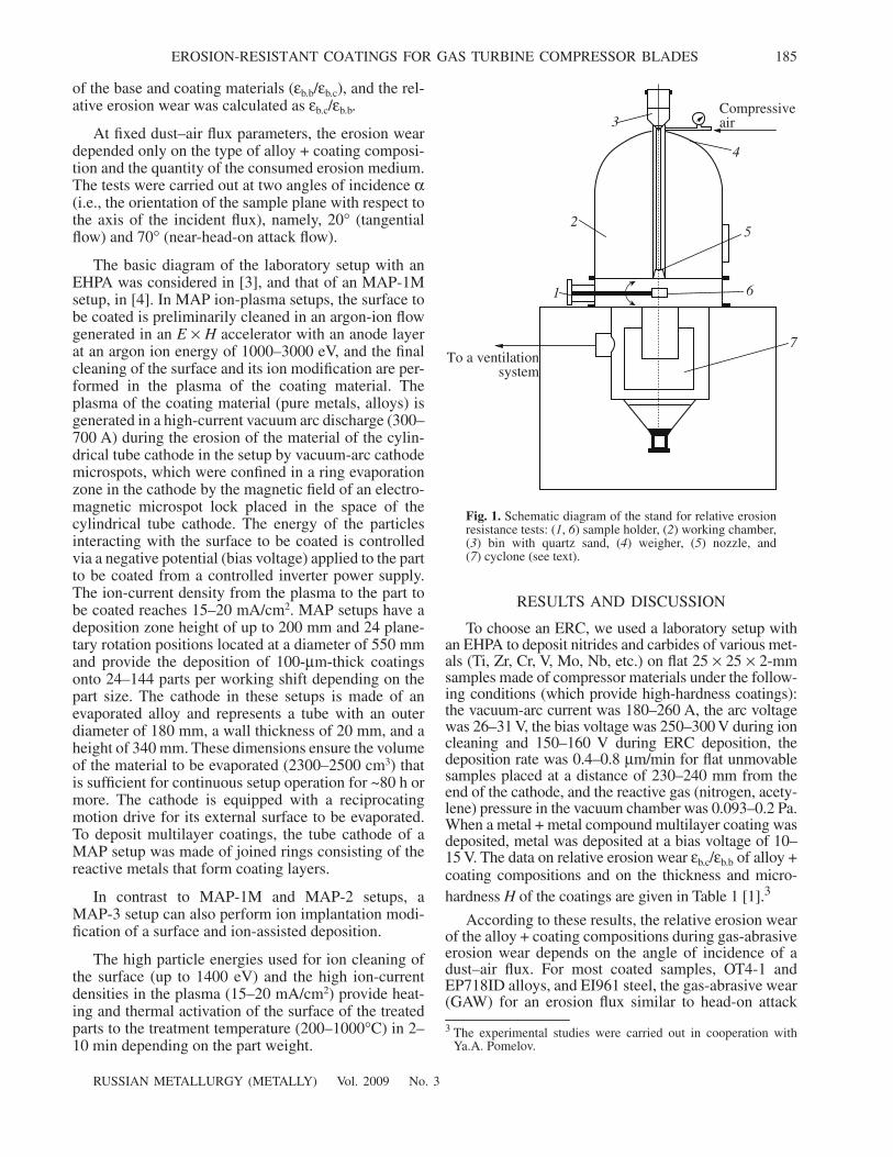
When studying the GAW of the samples with coat-ings based on low-stressed multilayer Ti + TiN, Ti + TiC,Zr + ZrN, Cr + Cr3C2, and V + VC compositions with athickness of ~1 µm of alternating layers (Fig. 2), we didnot reveal any advantages as compared to the corre-sponding single-layer coatings, which is likely to berelated to the low layer-by-layer fracture energy of amultilayer coating as compared to the corresponding sin-gle-layer coating with a thickness larger than the layerthickness in the multilayer compositions. ER-7 and
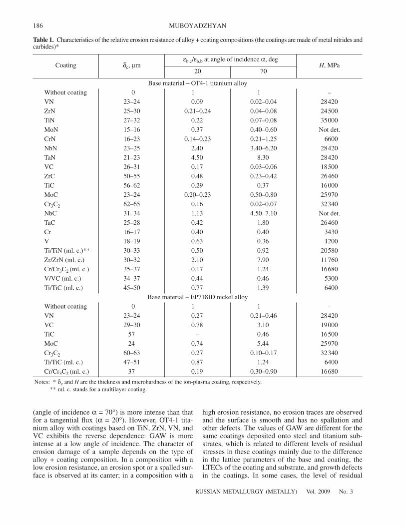
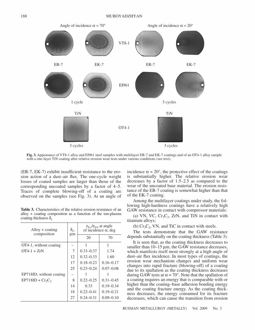
EK-7 multilayer coatings, which were designed at theUral Civil Aviation Plant and are intended for protectingcompressor blades upon the repair of TV2-117 andTV3-117 helicopter GTEs, also have low erosion resis-tance. We also studied VT8-1 titanium alloy and EI961steel with ER-7 and EK-7 coatings to find their relativeerosion wear in the aggressive medium of quartz sandwith fractions of 240 and 90 µm (Table 2). Figure 3shows the appearance of samples with multilayer ER-7and EK-7 coatings as compared to a sample with a mul-tilayer TiN coating subjected to relative erosion weartests in the aggressive medium of quartz sand with anaverage particle size of 240 and 300 µm, respectively.
The results obtained demonstrate that the erosionresistance of the ER-7 and EK-7 coatings depends sub-stantially on both the particle size of the erosionmedium and angle of incidence α. For example, in thecase of quartz sand with an average particle size of240 µm at an angle of incidence α = 70°, both coatings
(a) 20 µm 20 µm(b)
Fig. 2. Microstructures of (a) Zr + ZrN and (b) Cr + Cr3C2 multilayer coatings on an OT4-1 alloy deposited on an ion-plasma setupwith an EHPA.
Table 2. Relative erosion wear of a coating as a function of the fraction of quartz sand*
Steel (alloy) + coating compositionεb.c/εb.b at angle of incidence α, deg
20 70
EI961, without coating 1/1 1/1
EI961 + multilayer ER-7 (Ti–Zr–N) coating 0.5/0.038 5.9**/0.04
The same for EK-7 (Zr–Cr–N) 0.6/0.12 5.0**/0.14
VT8-1, without coating 1/1 1/1
VT8-1 + multilayer ER-7 (Ti–Zr–N) coating 0.3/0.036 3.7**/0.04
The same for EK-7 (Zr–Cr–N) 0.5/0.07 4.2**/0.07
Notes: * Numerator gives data for quartz sand with an average particle size of 240 µm, and the denominator gives data for an averageparticle size of 90 µm.
** Blowing-off of the coating (see Fig. 3).
188
RUSSIAN METALLURGY (METALLY) Vol. 2009 No. 3
MUBOYADZHYAN
(ER-7, EK-7) exhibit insufficient resistance to the ero-sion action of a dust–air flux. The one-cycle weightlosses of coated samples are larger than those of thecorresponding uncoated samples by a factor of 4–5.Traces of complete blowing-off of a coating areobserved on the samples (see Fig. 3). At an angle of
incidence α = 20°, the protective effect of the coatingsis substantially higher. The relative erosion weardecreases by a factor of 1.5–2.5 as compared to thewear of the uncoated base material. The erosion resis-tance of the ER-7 coating is somewhat higher than thatof the EK-7 coating.
Among the multilayer coatings under study, the fol-lowing high-hardness coatings have a relatively highGAW resistance in contact with compressor materials:
(a) VN, VC, Cr3C2, ZrN, and TiN in contact withtitanium alloys;
(b) Cr3C2, VN, and TiC in contact with steels.The tests demonstrate that the GAW resistance
depends substantially on the coating thickness (Table 3).It is seen that, as the coating thickness decreases to
smaller than 10–15 µm, the GAW resistance decreases,which manifests itself most strongly at a high angle ofdust–air flux incidence. In most types of coatings, theerosion wear mechanism changes and uniform wearchanges into rapid fracture (blowing-off) of a coatingdue to its spallation as the coating thickness decreasesduring GAW tests at α = 70°. Note that the spallation ofa coating requires an energy that is comparable with orhigher than the coating–base adhesion bonding energyand the coating fracture energy. As the coating thick-ness decreases, the energy consumed for its fracturedecreases, which can cause the transition from erosion
Angle of incidence α = 20°Angle of incidence α = 70°
VT8-1
ER-7 EK-7
EI961
1 cycle 3 cycles
OT4-1
ER-7 EK-7
TiNTiN
3 cycles3 cycles
Fig. 3. Appearance of VT8-1 alloy and EI961 steel samples with multilayer ER-7 and EK-7 coatings and of an OT4-1 alloy samplewith a one-layer TiN coating after relative erosion wear tests under various conditions (see text).
Table 3. Characteristics of the relative erosion resistance of analloy + coating composition as a function of the ion-plasmacoating thickness δc
Alloy + coatingcomposition
δc,µm
εb.c/εb.b at angleof incidence α, deg
20 70
OT4-1, without coating – 1 1
OT4-1 + ZrN 7 0.33–0.37 1.74
12 0.32–0.33 1.60
17 0.18–0.23 0.16–0.17
25 0.23–0.24 0.07–0.08
EP718ID, without coating – 1 1
EP718ID + Cr2C2 8 0.22–0.25 0.31–0.45
14 0.33 0.19–0.34
18 0.22–0.41 0.19–0.21
27 0.24–0.31 0.09–0.10
RUSSIAN METALLURGY (METALLY) Vol. 2009 No. 3
EROSION-RESISTANT COATINGS FOR GAS TURBINE COMPRESSOR BLADES 189
wear to coating spallation as the coating thicknessdecreases.
A similar effect is observed as the abrasive particlesize decreases, all other things being equal. In this case,the minimum coating thickness at which wear changesinto coating spallation decreases or the erosion resis-tance of a coating of a sufficient thickness increases.
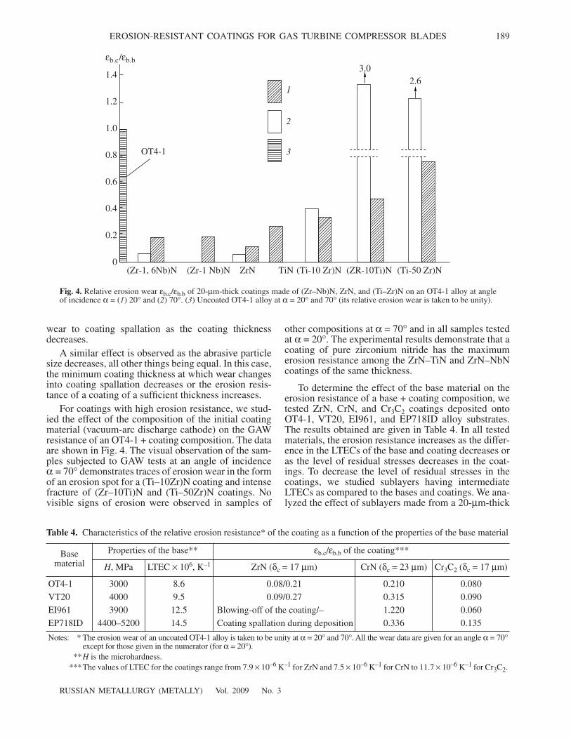
For coatings with high erosion resistance, we stud-ied the effect of the composition of the initial coatingmaterial (vacuum-arc discharge cathode) on the GAWresistance of an OT4-1 + coating composition. The dataare shown in Fig. 4. The visual observation of the sam-ples subjected to GAW tests at an angle of incidenceα = 70° demonstrates traces of erosion wear in the formof an erosion spot for a (Ti–10Zr)N coating and intensefracture of (Zr–10Ti)N and (Ti–50Zr)N coatings. Novisible signs of erosion were observed in samples of
other compositions at α = 70° and in all samples testedat α = 20°. The experimental results demonstrate that acoating of pure zirconium nitride has the maximumerosion resistance among the ZrN–TiN and ZrN–NbNcoatings of the same thickness.
To determine the effect of the base material on theerosion resistance of a base + coating composition, wetested ZrN, CrN, and Cr3C2 coatings deposited ontoOT4-1, VT20, EI961, and EP718ID alloy substrates.The results obtained are given in Table 4. In all testedmaterials, the erosion resistance increases as the differ-ence in the LTECs of the base and coating decreases oras the level of residual stresses decreases in the coat-ings. To decrease the level of residual stresses in thecoatings, we studied sublayers having intermediateLTECs as compared to the bases and coatings. We ana-lyzed the effect of sublayers made from a 20-µm-thick
Fig. 4. Relative erosion wear εb.c/εb.b of 20-µm-thick coatings made of (Zr–Nb)N, ZrN, and (Ti–Zr)N on an OT4-1 alloy at angleof incidence α = (1) 20° and (2) 70°. (3) Uncoated OT4-1 alloy at α = 20° and 70° (its relative erosion wear is taken to be unity).
Table 4. Characteristics of the relative erosion resistance* of the coating as a function of the properties of the base material
Basematerial
Properties of the base** εb.c/εb.b of the coating***
H, MPa LTEC × 106, K–1 ZrN (δc = 17 µm) CrN (δc = 23 µm) Cr3C2 (δc = 17 µm)
OT4-1 3000 8.6 0.08/0.21 0.210 0.080
VT20 4000 9.5 0.09/0.27 0.315 0.090
EI961 3900 12.5 Blowing-off of the coating/– 1.220 0.060
EP718ID 4400–5200 14.5 Coating spallation during deposition 0.336 0.135
Notes: * The erosion wear of an uncoated OT4-1 alloy is taken to be unity at α = 20° and 70°. All the wear data are given for an angle α = 70°except for those given in the numerator (for α = 20°).
**H is the microhardness. ***The values of LTEC for the coatings range from 7.9 × 10⁻⁶ K–1 for ZrN and 7.5 × 10⁻⁶ K–1 for CrN to 11.7 × 10⁻⁶ K–1 for Cr3C2.
εb.c/εb.b
1.4
1.2
1.0
0.8
0.6
0.4
0.2
0(Zr-1, 6Nb)N (Zr-1 Nb)N ZrN TiN (Ti-10 Zr)N (ZR-10Ti)N (Ti-50 Zr)N
1
2
3
3.02.6
OT4-1
190
RUSSIAN METALLURGY (METALLY) Vol. 2009 No. 3
MUBOYADZHYAN
VKNA alloy (Ni3Al system alloy), 20-µm-thickVZhL-2 alloy (nickel multicomponent alloy with car-bide hardening), 20-µm-thick zirconium, 17-µm-thicktitanium, 35-µm-thick nickel, and 9-µm-thick chro-mium. The results of the effect of these sublayers on therelative erosion wear are given in Table 5.
Our studies demonstrate that a VZhL-2 alloy sub-layer provides the highest protective properties amongthe alloy + sublayer + coating compositions. The effectof a sublayer on the erosion resistance of the coatingmainly manifests itself at a high angle of dust–air fluxincidence. The comparatively high erosion resistanceof the compositions with a VZhL-2 alloy sublayer canbe explained by the high hardness of the VZhL-2 alloycoating. On the whole, the application of the sublayers
made of the materials under study (zirconium, titanium,chromium, VZhL-2 alloy, VKNA alloy), which have ahigher LTEC than those of the nitrides and carbides ofmetals, does not increase the erosion resistance of thealloy + coating compositions. VZhL-2 alloy +ZrN,VZhL-2 alloy + Cr3C2, and Cr + Cr3C2 compositionscan be attributed to coatings with relatively high GAWerosion resistance.
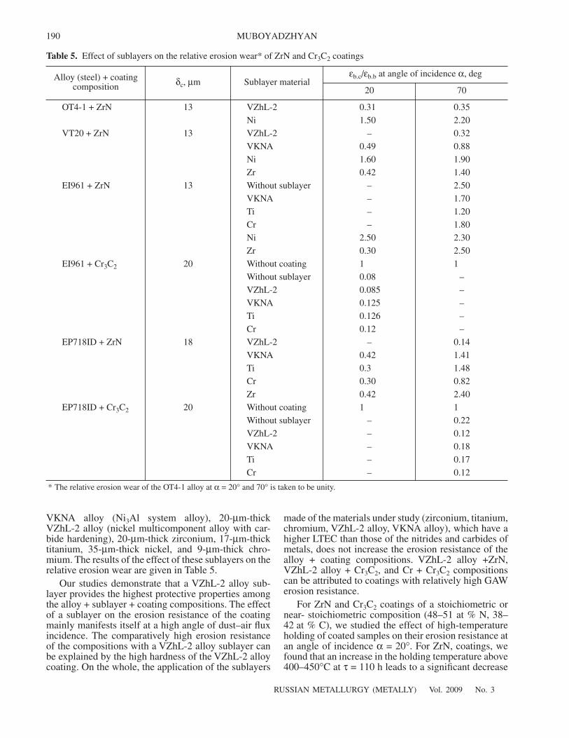
For ZrN and Cr3C2 coatings of a stoichiometric ornear- stoichiometric composition (48–51 at % N, 38–42 at % C), we studied the effect of high-temperatureholding of coated samples on their erosion resistance atan angle of incidence α = 20°. For ZrN, coatings, wefound that an increase in the holding temperature above400–450°C at τ = 110 h leads to a significant decrease
Table 5. Effect of sublayers on the relative erosion wear* of ZrN and Cr3C2 coatings
Alloy (steel) + coatingcomposition δc, µm Sublayer material
εb.c/εb.b at angle of incidence α, deg
20 70
OT4-1 + ZrN 13 VZhL-2 0.31 0.35
Ni 1.50 2.20
VT20 + ZrN 13 VZhL-2 – 0.32
VKNA 0.49 0.88
Ni 1.60 1.90
Zr 0.42 1.40
EI961 + ZrN 13 Without sublayer – 2.50
VKNA – 1.70
Ti – 1.20
Cr – 1.80
Ni 2.50 2.30
Zr 0.30 2.50
EI961 + Cr3C2 20 Without coating 1 1
Without sublayer 0.08 –
VZhL-2 0.085 –
VKNA 0.125 –
Ti 0.126 –
Cr 0.12 –
EP718ID + ZrN 18 VZhL-2 – 0.14
VKNA 0.42 1.41
Ti 0.3 1.48
Cr 0.30 0.82
Zr 0.42 2.40
EP718ID + Cr3C2 20 Without coating 1 1
Without sublayer – 0.22
VZhL-2 – 0.12
VKNA – 0.18
Ti – 0.17
Cr – 0.12
* The relative erosion wear of the OT4-1 alloy at α = 20° and 70° is taken to be unity.
RUSSIAN METALLURGY (METALLY) Vol. 2009 No. 3
EROSION-RESISTANT COATINGS FOR GAS TURBINE COMPRESSOR BLADES 191
in the erosion resistance (Fig. 5). For Cr3C2 coatings inthe temperature range 500–600°C, we detected anincrease in the erosion resistance (Fig. 5), which islikely to be related to a change in the surface-layer com-position and the formation of oxycarbidies on the sam-ple surface.
The GAW resistance of the alloy + coating compo-sition depends more strongly on the structure–phasestate of the coating, which is determined by the coatingdeposition parameters. The main parameters in thisprocess are the substrate temperature during deposi-tion, the reactive-gas pressure, the bias potential, andthe deposition rate. In turn, the substrate temperature iscontrolled by the bias potential and the ion-current den-sity at the substrate, which depends on the metallicplasma generation rate by cathode microspots and isproportional to the vacuum-arc discharge current [5].For example, the erosion resistance of ZrN coatingsbecomes high at a substrate temperature of 500–600°C(Fig. 6), and the substrate temperature is a stronger fac-tor than the substrate potential.
The increase in the erosion resistance of the compo-sitions with a ZrN coating is likely to be due to theimprovement of the coating crystal structure as the sub-strate temperature increases. Vacuum annealing of thecoated samples at 600°C for 3 h leads to the homogeni-zation of the coating structure and a noticeable increasein the ERC. For example, at an angle of incidence α =20° for a ZrN (or TiN) coating, the relative erosion weardecreases from 0.21 to 0.08 (from 0.22 to 0.13); at α =70°C, it decreases from 0.06 to 0.05 (from 0.08 to 0.07).
For alloy + coating compositions that have high ero-sion resistance and are deposited at various substrate
temperatures, compositions with Cr3C2 and VN coat-ings are less sensitive to the substrate temperature thancompositions with ZrN and VC coatings. A change inthe bias potential in the range 60–150 V during deposi-tion of these coatings does not affect their erosion resis-tance. However, for compositions with ZrN and VCcoatings, a decrease in the bias potential to 60–75 Vduring deposition results in a sharp decrease in the pro-tective properties of these coatings.
X-ray diffraction studies demonstrate that the ZrNcoatings deposited onto a fixed substrate at a substratetemperature ts = 500–1100°C and a bias voltage of 0–100 V have a crystal lattice with a main phase constituentof ZrN (B1) and a low content (CV ≈ 3–5%) of theα-Zr phase (drop phase). The content of the latter phasedecreases to zero as substrate temperature ts increases to1100°C. The lattice parameter of ZrN (a = 3.583 ±0.002 Å) is almost independent of the deposition param-eters. The half-width of the (313) line decreases sharplyfrom 3.3 ± 0.3 to 1.3 ± 0.2 deg as the temperatureincreases from 500 to 1100°C, which also indicates theimprovement of the crystal lattice of the compound [6].
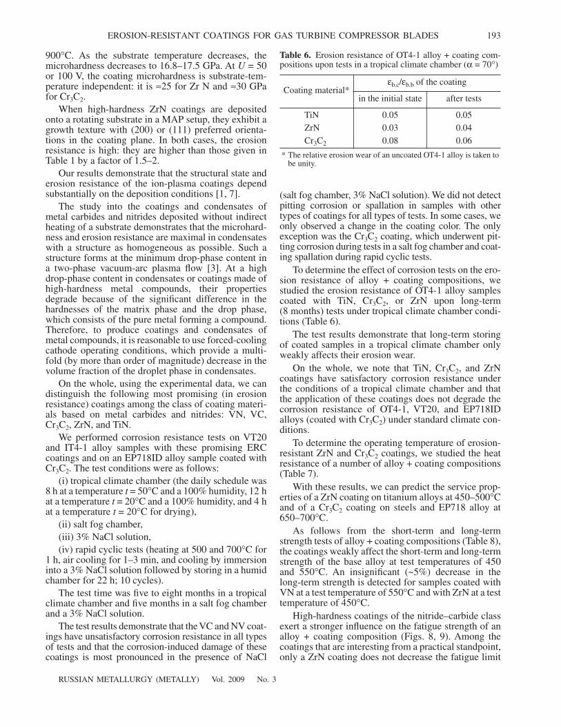
Cr–C coatings deposited under similar conditions atts > 700°C are crystalline and represented by the Cr3C2carbide (structure type D510) with lattice parametersa = 11.48, b = 5.53, and c = 5.53 Å. Figure 7a shows thetypical X-ray diffraction pattern of the Cr3C2 coatingdeposited at ts = 900°C that was taken using CrKα radi-ation. The X-ray diffraction pattern is seen to contain avery strong (002) line and a weak (410) line (as com-pared to a polycrystalline textureless standard) and tohave no other (HK0) lines. This indicates a strong (001)texture. As the temperature increases, the degree of tex-
εb.c/εb.b
1.2
0.8
0.6
0.4
0.2
0t, °Cτ, h
20 20100
400110
450110
50050
550110
500110
700110
20 500110
600110
700100
1
2
3
4
1.0
EP718ID
VT20 EP718ID
Fig. 5. Relative erosion wear of (1) VT20 alloy + ZrN amd (2) EP718ID alloy + Cr3C2 compositions at an angle of incidence α = 20°vs. temperature t and time τ of their exposition in air. (3) Uncoated EP718ID alloy and (4) uncoated VT20 and EP718ID alloy sam-ples at α = 20° and 70° (the relative erosion wear is taken to be unity).
192
RUSSIAN METALLURGY (METALLY) Vol. 2009 No. 3
MUBOYADZHYAN
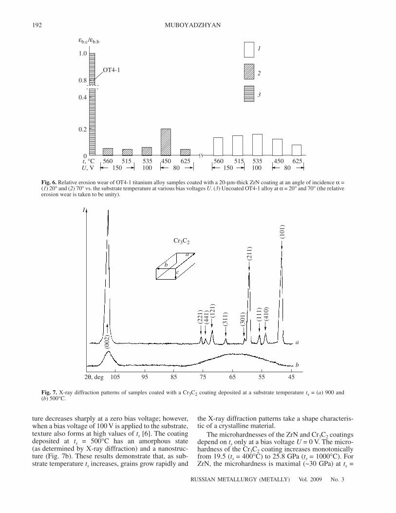
ture decreases sharply at a zero bias voltage; however,when a bias voltage of 100 V is applied to the substrate,texture also forms at high values of ts [6]. The coatingdeposited at ts = 500°C has an amorphous state(as determined by X-ray diffraction) and a nanostruc-ture (Fig. 7b). These results demonstrate that, as sub-strate temperature ts increases, grains grow rapidly and
the X-ray diffraction patterns take a shape characteris-tic of a crystalline material.
The microhardnesses of the ZrN and Cr3C2 coatingsdepend on ts only at a bias voltage U = 0 V. The micro-hardness of the Cr3C2 coating increases monotonicallyfrom 19.5 (ts = 400°C) to 25.8 GPa (ts = 1000°C). ForZrN, the microhardness is maximal (~30 GPa) at ts =
1.0
0.8
0.4
0.2
0t, °CU, V
560150
515 535100
45080
625 560150
515 535100
45080
625
1
2
3
εb.c/εb.b
OT4-1
Fig. 6. Relative erosion wear of OT4-1 titanium alloy samples coated with a 20-µm-thick ZrN coating at an angle of incidence α =(1) 20° and (2) 70° vs. the substrate temperature at various bias voltages U. (3) Uncoated OT4-1 alloy at α = 20° and 70° (the relativeerosion wear is taken to be unity).
105 95 85 75 65 55 45
a
bc
(221
)(4
41)
(121
)
(311
)
(301
)(2
11)
(111
)(4
10)
(101
)
a
b
Cr3C2
2θ, deg
I
Fig. 7. X-ray diffraction patterns of samples coated with a Cr3C2 coating deposited at a substrate temperature ts = (a) 900 and(b) 500°C.
(002
)
RUSSIAN METALLURGY (METALLY) Vol. 2009 No. 3
EROSION-RESISTANT COATINGS FOR GAS TURBINE COMPRESSOR BLADES 193
900°C. As the substrate temperature decreases, themicrohardness decreases to 16.8–17.5 GPa. At U = 50or 100 V, the coating microhardness is substrate-tem-perature independent: it is ≈25 for Zr N and ≈30 GPafor Cr3C2.
When high-hardness ZrN coatings are depositedonto a rotating substrate in a MAP setup, they exhibit agrowth texture with (200) or (111) preferred orienta-tions in the coating plane. In both cases, the erosionresistance is high: they are higher than those given inTable 1 by a factor of 1.5–2.
Our results demonstrate that the structural state anderosion resistance of the ion-plasma coatings dependsubstantially on the deposition conditions [1, 7].
The study into the coatings and condensates ofmetal carbides and nitrides deposited without indirectheating of a substrate demonstrates that the microhard-ness and erosion resistance are maximal in condensateswith a structure as homogeneous as possible. Such astructure forms at the minimum drop-phase content ina two-phase vacuum-arc plasma flow [3]. At a highdrop-phase content in condensates or coatings made ofhigh-hardness metal compounds, their propertiesdegrade because of the significant difference in thehardnesses of the matrix phase and the drop phase,which consists of the pure metal forming a compound.Therefore, to produce coatings and condensates ofmetal compounds, it is reasonable to use forced-coolingcathode operating conditions, which provide a multi-fold (by more than order of magnitude) decrease in thevolume fraction of the droplet phase in condensates.
On the whole, using the experimental data, we candistinguish the following most promising (in erosionresistance) coatings among the class of coating materi-als based on metal carbides and nitrides: VN, VC,Cr3C2, ZrN, and TiN.
We performed corrosion resistance tests on VT20and IT4-1 alloy samples with these promising ERCcoatings and on an EP718ID alloy sample coated withCr3C2. The test conditions were as follows:
(i) tropical climate chamber (the daily schedule was8 h at a temperature t = 50°C and a 100% humidity, 12 hat a temperature t = 20°C and a 100% humidity, and 4 hat a temperature t = 20°C for drying),
(ii) salt fog chamber,(iii) 3% NaCl solution,(iv) rapid cyclic tests (heating at 500 and 700°C for
1 h, air cooling for 1–3 min, and cooling by immersioninto a 3% NaCl solution followed by storing in a humidchamber for 22 h; 10 cycles).
The test time was five to eight months in a tropicalclimate chamber and five months in a salt fog chamberand a 3% NaCl solution.
The test results demonstrate that the VC and NV coat-ings have unsatisfactory corrosion resistance in all typesof tests and that the corrosion-induced damage of thesecoatings is most pronounced in the presence of NaCl
(salt fog chamber, 3% NaCl solution). We did not detectpitting corrosion or spallation in samples with othertypes of coatings for all types of tests. In some cases, weonly observed a change in the coating color. The onlyexception was the Cr3C2 coating, which underwent pit-ting corrosion during tests in a salt fog chamber and coat-ing spallation during rapid cyclic tests.
To determine the effect of corrosion tests on the ero-sion resistance of alloy + coating compositions, westudied the erosion resistance of OT4-1 alloy samplescoated with TiN, Cr3C2, or ZrN upon long-term(8 months) tests under tropical climate chamber condi-tions (Table 6).
The test results demonstrate that long-term storingof coated samples in a tropical climate chamber onlyweakly affects their erosion wear.
On the whole, we note that TiN, Cr3C2, and ZrNcoatings have satisfactory corrosion resistance underthe conditions of a tropical climate chamber and thatthe application of these coatings does not degrade thecorrosion resistance of OT4-1, VT20, and EP718IDalloys (coated with Cr3C2) under standard climate con-ditions.
To determine the operating temperature of erosion-resistant ZrN and Cr3C2 coatings, we studied the heatresistance of a number of alloy + coating compositions(Table 7).
With these results, we can predict the service prop-erties of a ZrN coating on titanium alloys at 450–500°Cand of a Cr3C2 coating on steels and EP718 alloy at650–700°C.
As follows from the short-term and long-termstrength tests of alloy + coating compositions (Table 8),the coatings weakly affect the short-term and long-termstrength of the base alloy at test temperatures of 450and 550°C. An insignificant (~5%) decrease in thelong-term strength is detected for samples coated withVN at a test temperature of 550°C and with ZrN at a testtemperature of 450°C.
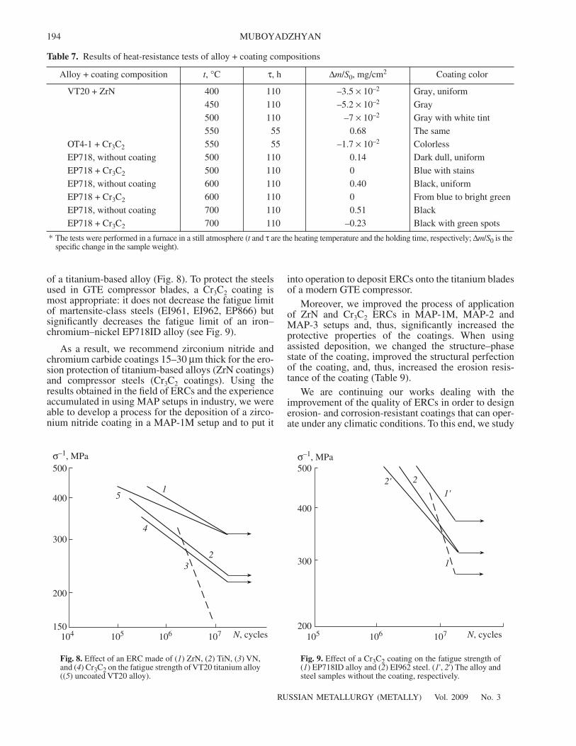
High-hardness coatings of the nitride–carbide classexert a stronger influence on the fatigue strength of analloy + coating composition (Figs. 8, 9). Among thecoatings that are interesting from a practical standpoint,only a ZrN coating does not decrease the fatigue limit
Table 6. Erosion resistance of OT4-1 alloy + coating com-positions upon tests in a tropical climate chamber (α = 70°)
Coating material*εb.c/εb.b of the coating
in the initial state after tests
TiN 0.05 0.05
ZrN 0.03 0.04
Cr3C2 0.08 0.06
* The relative erosion wear of an uncoated OT4-1 alloy is taken tobe unity.
194
RUSSIAN METALLURGY (METALLY) Vol. 2009 No. 3
MUBOYADZHYAN
of a titanium-based alloy (Fig. 8). To protect the steelsused in GTE compressor blades, a Cr3C2 coating ismost appropriate: it does not decrease the fatigue limitof martensite-class steels (EI961, EI962, EP866) butsignificantly decreases the fatigue limit of an iron–chromium–nickel EP718ID alloy (see Fig. 9).
As a result, we recommend zirconium nitride andchromium carbide coatings 15–30 µm thick for the ero-sion protection of titanium-based alloys (ZrN coatings)and compressor steels (Cr3C2 coatings). Using theresults obtained in the field of ERCs and the experienceaccumulated in using MAP setups in industry, we wereable to develop a process for the deposition of a zirco-nium nitride coating in a MAP-1M setup and to put it
into operation to deposit ERCs onto the titanium bladesof a modern GTE compressor.
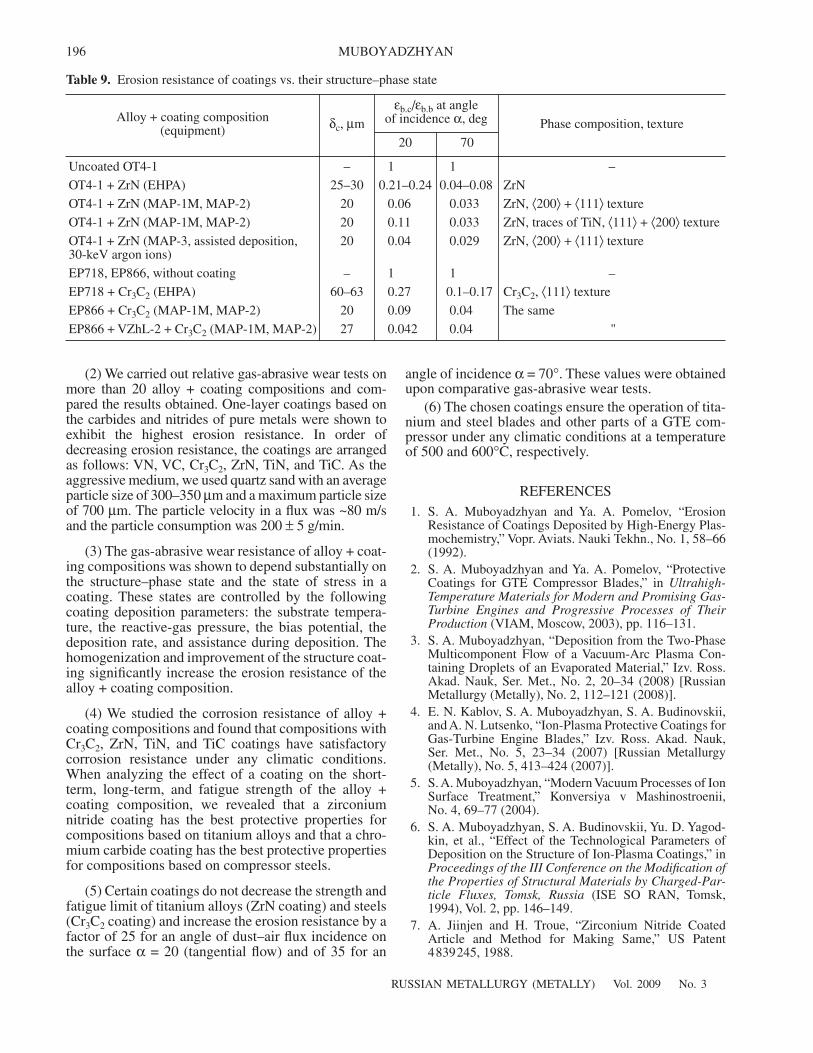
Moreover, we improved the process of applicationof ZrN and Cr3C2 ERCs in MAP-1M, MAP-2 andMAP-3 setups and, thus, significantly increased theprotective properties of the coatings. When usingassisted deposition, we changed the structure–phasestate of the coating, improved the structural perfectionof the coating, and, thus, increased the erosion resis-tance of the coating (Table 9).
We are continuing our works dealing with theimprovement of the quality of ERCs in order to designerosion- and corrosion-resistant coatings that can oper-ate under any climatic conditions. To this end, we study
Table 7. Results of heat-resistance tests of alloy + coating compositions
Alloy + coating composition t, °C τ, h ∆m/S0, mg/cm2 Coating color
VT20 + ZrN 400 110 –3.5 × 10⁻² Gray, uniform
450 110 –5.2 × 10⁻² Gray
500 110 –7 × 10⁻² Gray with white tint
550 55 0.68 The same
OT4-1 + Cr3C2 550 55 –1.7 × 10⁻² Colorless
EP718, without coating 500 110 0.14 Dark dull, uniform
EP718 + Cr3C2 500 110 0 Blue with stains
EP718, without coating 600 110 0.40 Black, uniform
EP718 + Cr3C2 600 110 0 From blue to bright green
EP718, without coating 700 110 0.51 Black
EP718 + Cr3C2 700 110 –0.23 Black with green spots
* The tests were performed in a furnace in a still atmosphere (t and τ are the heating temperature and the holding time, respectively; ∆m/S0 is thespecific change in the sample weight).
σ–1, MPa500
400
300
200
150104 105 106 107 N, cycles
1
23
4
5
Fig. 8. Effect of an ERC made of (1) ZrN, (2) TiN, (3) VN,and (4) Cr3C2 on the fatigue strength of VT20 titanium alloy((5) uncoated VT20 alloy).
500
400
300
200105 106 107
1'
2
1
2'
σ–1, MPa
N, cycles
Fig. 9. Effect of a Cr3C2 coating on the fatigue strength of(1) EP718ID alloy and (2) EI962 steel. (1', 2') The alloy andsteel samples without the coating, respectively.
RUSSIAN METALLURGY (METALLY) Vol. 2009 No. 3
EROSION-RESISTANT COATINGS FOR GAS TURBINE COMPRESSOR BLADES 195
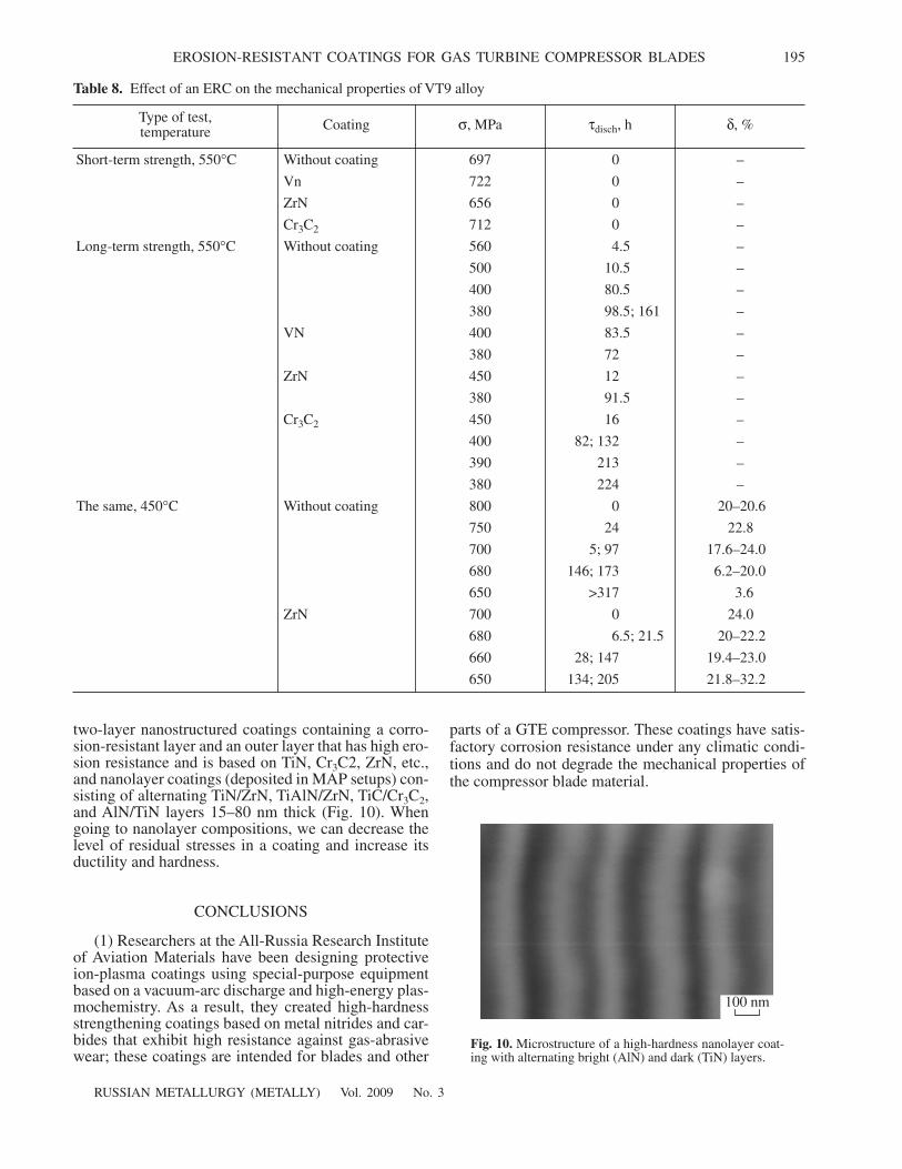
two-layer nanostructured coatings containing a corro-sion-resistant layer and an outer layer that has high ero-sion resistance and is based on TiN, Cr3C2, ZrN, etc.,and nanolayer coatings (deposited in MAP setups) con-sisting of alternating TiN/ZrN, TiAlN/ZrN, TiC/Cr3C2,and AlN/TiN layers 15–80 nm thick (Fig. 10). Whengoing to nanolayer compositions, we can decrease thelevel of residual stresses in a coating and increase itsductility and hardness.
CONCLUSIONS
(1) Researchers at the All-Russia Research Instituteof Aviation Materials have been designing protectiveion-plasma coatings using special-purpose equipmentbased on a vacuum-arc discharge and high-energy plas-mochemistry. As a result, they created high-hardnessstrengthening coatings based on metal nitrides and car-bides that exhibit high resistance against gas-abrasivewear; these coatings are intended for blades and other
parts of a GTE compressor. These coatings have satis-factory corrosion resistance under any climatic condi-tions and do not degrade the mechanical properties ofthe compressor blade material.
Table 8. Effect of an ERC on the mechanical properties of VT9 alloy
Type of test,temperature Coating σ, MPa τdisch, h δ, %
Short-term strength, 550°C Without coating 697 0 –
Vn 722 0 –
ZrN 656 0 –
Cr3C2 712 0 –
Long-term strength, 550°C Without coating 560 4.5 –
500 10.5 –
400 80.5 –
380 98.5; 161 –
VN 400 83.5 –
380 72 –
ZrN 450 12 –
380 91.5 –
Cr3C2 450 16 –
400 82; 132 –
390 213 –
380 224 –
The same, 450°C Without coating 800 0 20–20.6
750 24 22.8
700 5; 97 17.6–24.0
680 146; 173 6.2–20.0
650 >317 3.6
ZrN 700 0 24.0
680 6.5; 21.5 20–22.2
660 28; 147 19.4–23.0
650 134; 205 21.8–32.2
100 nm
Fig. 10. Microstructure of a high-hardness nanolayer coat-ing with alternating bright (AlN) and dark (TiN) layers.
196
RUSSIAN METALLURGY (METALLY) Vol. 2009 No. 3
MUBOYADZHYAN
(2) We carried out relative gas-abrasive wear tests onmore than 20 alloy + coating compositions and com-pared the results obtained. One-layer coatings based onthe carbides and nitrides of pure metals were shown toexhibit the highest erosion resistance. In order ofdecreasing erosion resistance, the coatings are arrangedas follows: VN, VC, Cr3C2, ZrN, TiN, and TiC. As theaggressive medium, we used quartz sand with an averageparticle size of 300–350 µm and a maximum particle sizeof 700 µm. The particle velocity in a flux was ~80 m/sand the particle consumption was 200 ± 5 g/min.
(3) The gas-abrasive wear resistance of alloy + coat-ing compositions was shown to depend substantially onthe structure–phase state and the state of stress in acoating. These states are controlled by the followingcoating deposition parameters: the substrate tempera-ture, the reactive-gas pressure, the bias potential, thedeposition rate, and assistance during deposition. Thehomogenization and improvement of the structure coat-ing significantly increase the erosion resistance of thealloy + coating composition.
(4) We studied the corrosion resistance of alloy +coating compositions and found that compositions withCr3C2, ZrN, TiN, and TiC coatings have satisfactorycorrosion resistance under any climatic conditions.When analyzing the effect of a coating on the short-term, long-term, and fatigue strength of the alloy +coating composition, we revealed that a zirconiumnitride coating has the best protective properties forcompositions based on titanium alloys and that a chro-mium carbide coating has the best protective propertiesfor compositions based on compressor steels.
(5) Certain coatings do not decrease the strength andfatigue limit of titanium alloys (ZrN coating) and steels(Cr3C2 coating) and increase the erosion resistance by afactor of 25 for an angle of dust–air flux incidence onthe surface α = 20 (tangential flow) and of 35 for an
angle of incidence α = 70°. These values were obtainedupon comparative gas-abrasive wear tests.
(6) The chosen coatings ensure the operation of tita-nium and steel blades and other parts of a GTE com-pressor under any climatic conditions at a temperatureof 500 and 600°C, respectively.
REFERENCES1. S. A. Muboyadzhyan and Ya. A. Pomelov, “Erosion
Resistance of Coatings Deposited by High-Energy Plas-mochemistry,” Vopr. Aviats. Nauki Tekhn., No. 1, 58–66(1992).
2. S. A. Muboyadzhyan and Ya. A. Pomelov, “ProtectiveCoatings for GTE Compressor Blades,” in Ultrahigh-Temperature Materials for Modern and Promising Gas-Turbine Engines and Progressive Processes of TheirProduction (VIAM, Moscow, 2003), pp. 116–131.
3. S. A. Muboyadzhyan, “Deposition from the Two-PhaseMulticomponent Flow of a Vacuum-Arc Plasma Con-taining Droplets of an Evaporated Material,” Izv. Ross.Akad. Nauk, Ser. Met., No. 2, 20–34 (2008) [RussianMetallurgy (Metally), No. 2, 112–121 (2008)].
4. E. N. Kablov, S. A. Muboyadzhyan, S. A. Budinovskii,and A. N. Lutsenko, “Ion-Plasma Protective Coatings forGas-Turbine Engine Blades,” Izv. Ross. Akad. Nauk,Ser. Met., No. 5, 23–34 (2007) [Russian Metallurgy(Metally), No. 5, 413–424 (2007)].
5. S. A. Muboyadzhyan, “Modern Vacuum Processes of IonSurface Treatment,” Konversiya v Mashinostroenii,No. 4, 69–77 (2004).
6. S. A. Muboyadzhyan, S. A. Budinovskii, Yu. D. Yagod-kin, et al., “Effect of the Technological Parameters ofDeposition on the Structure of Ion-Plasma Coatings,” inProceedings of the III Conference on the Modification ofthe Properties of Structural Materials by Charged-Par-ticle Fluxes, Tomsk, Russia (ISE SO RAN, Tomsk,1994), Vol. 2, pp. 146–149.
7. A. Jiinjen and H. Troue, “Zirconium Nitride CoatedArticle and Method for Making Same,” US Patent4839245, 1988.
Table 9. Erosion resistance of coatings vs. their structure–phase state
Alloy + coating composition(equipment) δc, µm
εb.c/εb.b at angleof incidence α, deg Phase composition, texture
20 70
Uncoated OT4-1 – 1 1 –
OT4-1 + ZrN (EHPA) 25–30 0.21–0.24 0.04–0.08 ZrN
OT4-1 + ZrN (MAP-1M, MAP-2) 20 0.06 0.033 ZrN, ⟨200⟩ + ⟨111⟩ texture
OT4-1 + ZrN (MAP-1M, MAP-2) 20 0.11 0.033 ZrN, traces of TiN, ⟨111⟩ + ⟨200⟩ texture
OT4-1 + ZrN (MAP-3, assisted deposition,30-keV argon ions)
20 0.04 0.029 ZrN, ⟨200⟩ + ⟨111⟩ texture
EP718, EP866, without coating – 1 1 –
EP718 + Cr3C2 (EHPA) 60–63 0.27 0.1–0.17 Cr3C2, ⟨111⟩ texture
EP866 + Cr3C2 (MAP-1M, MAP-2) 20 0.09 0.04 The same
EP866 + VZhL-2 + Cr3C2 (MAP-1M, MAP-2) 27 0.042 0.04 "