Embed Size (px)
Citation preview
Page 1
This guide is intended for volunteers or contractors performing erosion
control as a part of a trail maintenance program.
The methods in this guide require only the use of hand tools. Machinery
is not required but could be used if available.
The materials used are site-sourced when possible. When non-site
sourced materials are required, effort has being made to specify light
weight, low cost and widely available items.
There are many variations of the methods indicated and not all
variations are shown. Local conditions may dictate an alternate method.
General Guidelines
1. Trails should not have water running down the trail as a result of rain, seepage or snow melt
subject to the following:
a. It is permissible to allow water to flow on trails provided that the amount of water
flow will not cause erosion.
b. The water flow is controlled by suitable erosion control works or methods.
2. No trail should have standing water (puddles) on it subject to the following:
a. Standing water that forms an area less than 900 sq cm (1 sq ft) is permitted following
rain or snow melt provided that the water will drain or soak away within a reasonable
time period.
Erosion Control for Recreational Trails
Page 2
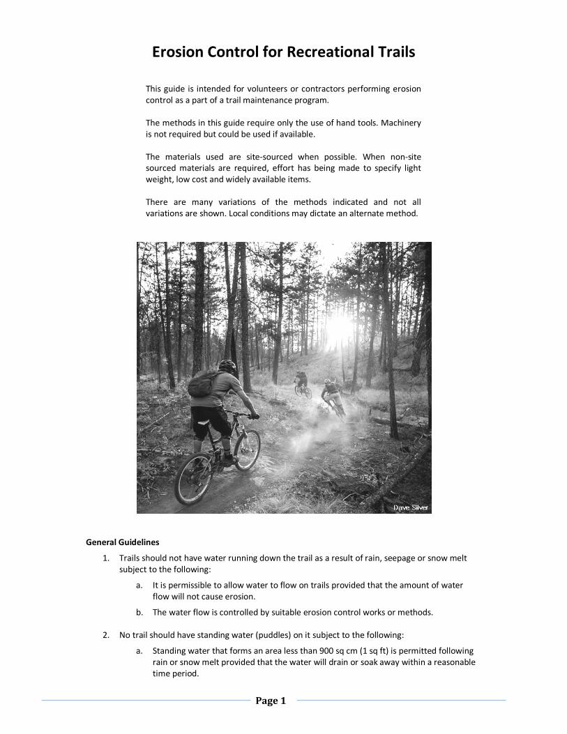
Sheet Water Flow
Slough Berm
Erosion Control Methods
Out-Slope
The trail bed should have a 5
percent slope so that sheet flow
water will travel across the trail and
continue down the slope.
Remove slough and berm and use
this material to create a sloping trail
tread.
Page 3
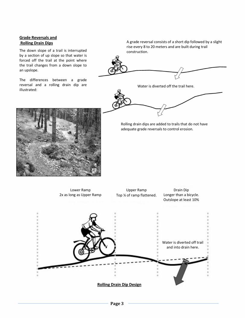
A grade reversal consists of a short dip followed by a slight
rise every 8 to 20 meters and are built during trail
construction.
Water is diverted off the trail here.
Rolling drain dips are added to trails that do not have
adequate grade reversals to control erosion.
Grade Reversals and
Rolling Drain Dips
The down slope of a trail is interrupted
by a section of up slope so that water is
forced off the trail at the point where
the trail changes from a down slope to
an upslope.
The differences between a grade
reversal and a rolling drain dip are
illustrated:
Lower Ramp
2x as long as Upper Ramp
Upper Ramp
Top ¼ of ramp flattened.
Drain Dip
Longer than a bicycle.
Outslope at least 10%
Water is diverted off trail
and into drain here.
Rolling Drain Dip Design
Page 4
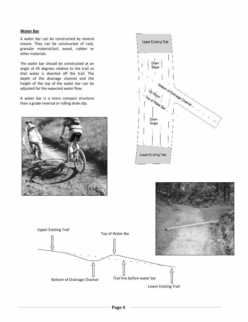
Water Bar Overhead
View
Upper Existing Trail
Lower Existing Trail
Top of Water Bar
Bottom of Drainage Channel Trail line before water bar
Water Bar
A water bar can be constructed by several
means. They can be constructed of rock,
granular material/soil, wood, rubber or
other materials.
The water bar should be constructed at an
angle of 45 degrees relative to the trail so
that water is diverted off the trail. The
depth of the drainage channel and the
height of the top of the water bar can be
adjusted for the expected water flow.
A water bar is a more compact structure
than a grade reversal or rolling drain dip.
Page 5
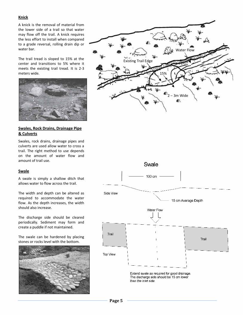
Knick
A knick is the removal of material from
the lower side of a trail so that water
may flow off the trail. A knick requires
the less effort to install when compared
to a grade reversal, rolling drain dip or
water bar.
The trail tread is sloped to 15% at the
center and transitions to 5% where it
meets the existing trail tread. It is 2-3
meters wide.
Swales, Rock Drains, Drainage Pipe
& Culverts
Swales, rock drains, drainage pipes and
culverts are used allow water to cross a
trail. The right method to use depends
on the amount of water flow and
amount of trail use.
Swale
A swale is simply a shallow ditch that
allows water to flow across the trail.
The width and depth can be altered as
required to accommodate the water
flow. As the depth increases, the width
should also increase.
The discharge side should be cleared
periodically. Sediment may form and
create a puddle if not maintained.
The swale can be hardened by placing
stones or rocks level with the bottom.
Water Flow
2 – 3m Wide
15%
Existing Trail Edge
Page 6
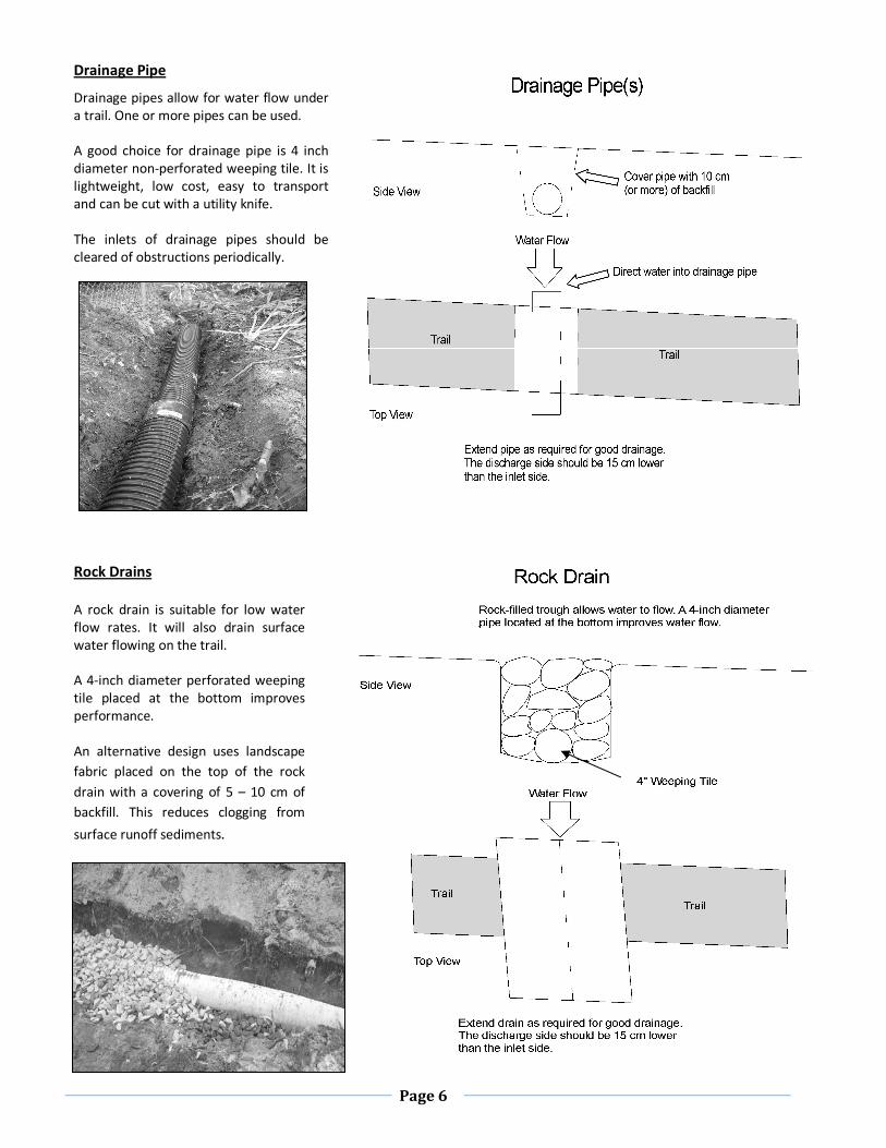
Drainage Pipe
Drainage pipes allow for water flow under
a trail. One or more pipes can be used.
A good choice for drainage pipe is 4 inch
diameter non-perforated weeping tile. It is
lightweight, low cost, easy to transport
and can be cut with a utility knife.
The inlets of drainage pipes should be
cleared of obstructions periodically.
Rock Drains
A rock drain is suitable for low water
flow rates. It will also drain surface
water flowing on the trail.
A 4-inch diameter perforated weeping
tile placed at the bottom improves
performance.
An alternative design uses landscape
fabric placed on the top of the rock
drain with a covering of 5 – 10 cm of
backfill. This reduces clogging from
surface runoff sediments.
Page 7
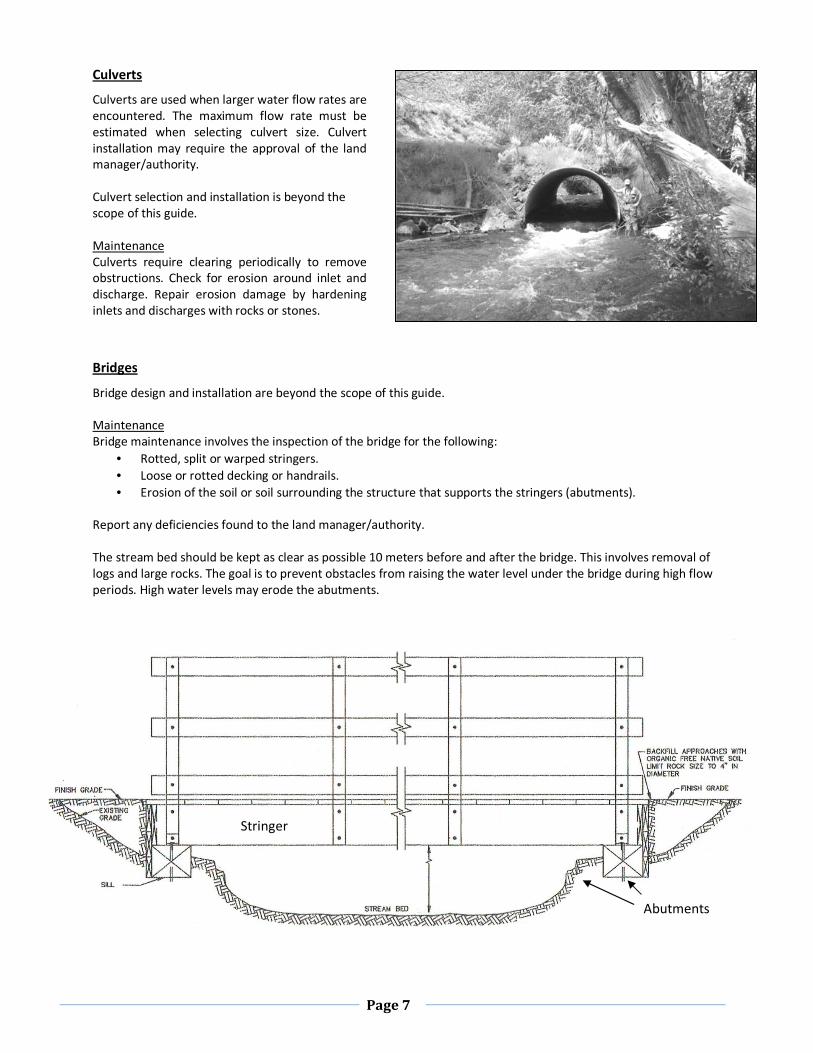
Culverts
Culverts are used when larger water flow rates are
encountered. The maximum flow rate must be
estimated when selecting culvert size. Culvert
installation may require the approval of the land
manager/authority.
Culvert selection and installation is beyond the
scope of this guide.
Maintenance
Culverts require clearing periodically to remove
obstructions. Check for erosion around inlet and
discharge. Repair erosion damage by hardening
inlets and discharges with rocks or stones.
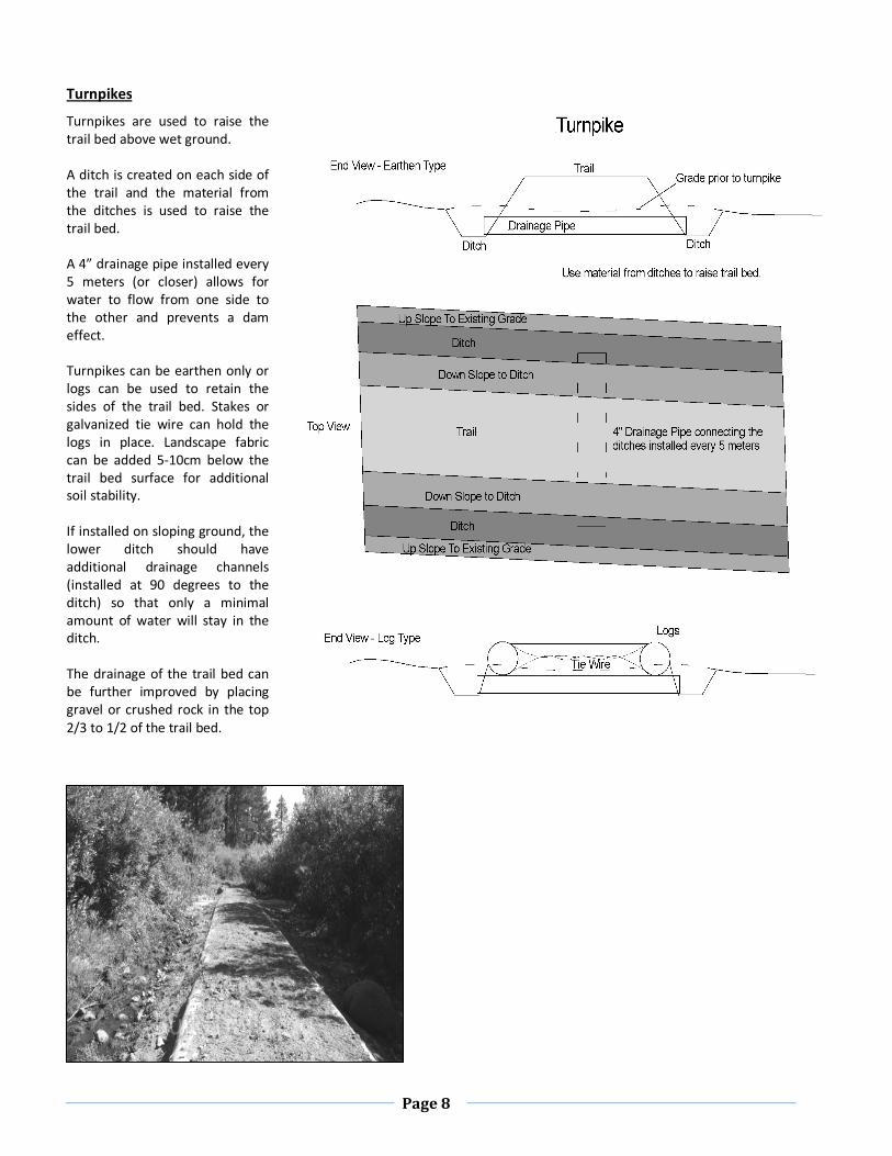
Stringer
Abutments
Bridges
Bridge design and installation are beyond the scope of this guide.
Maintenance
Bridge maintenance involves the inspection of the bridge for the following:
• Rotted, split or warped stringers.
• Loose or rotted decking or handrails.
• Erosion of the soil or soil surrounding the structure that supports the stringers (abutments).
Report any deficiencies found to the land manager/authority.
The stream bed should be kept as clear as possible 10 meters before and after the bridge. This involves removal of
logs and large rocks. The goal is to prevent obstacles from raising the water level under the bridge during high flow
periods. High water levels may erode the abutments.
Page 8
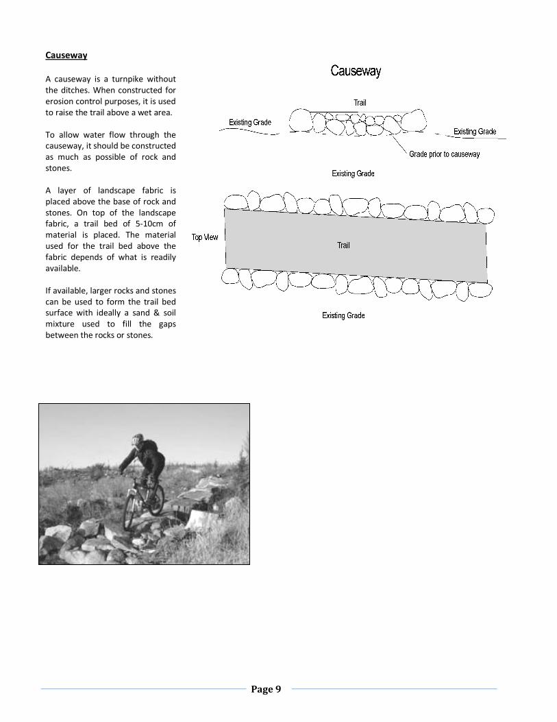
Turnpikes
Turnpikes are used to raise the
trail bed above wet ground.
A ditch is created on each side of
the trail and the material from
the ditches is used to raise the
trail bed.
A 4” drainage pipe installed every
5 meters (or closer) allows for
water to flow from one side to
the other and prevents a dam
effect.
Turnpikes can be earthen only or
logs can be used to retain the
sides of the trail bed. Stakes or
galvanized tie wire can hold the
logs in place. Landscape fabric
can be added 5-10cm below the
trail bed surface for additional
soil stability.
If installed on sloping ground, the
lower ditch should have
additional drainage channels
(installed at 90 degrees to the
ditch) so that only a minimal
amount of water will stay in the
ditch.
The drainage of the trail bed can
be further improved by placing
gravel or crushed rock in the top
2/3 to 1/2 of the trail bed.
Page 9
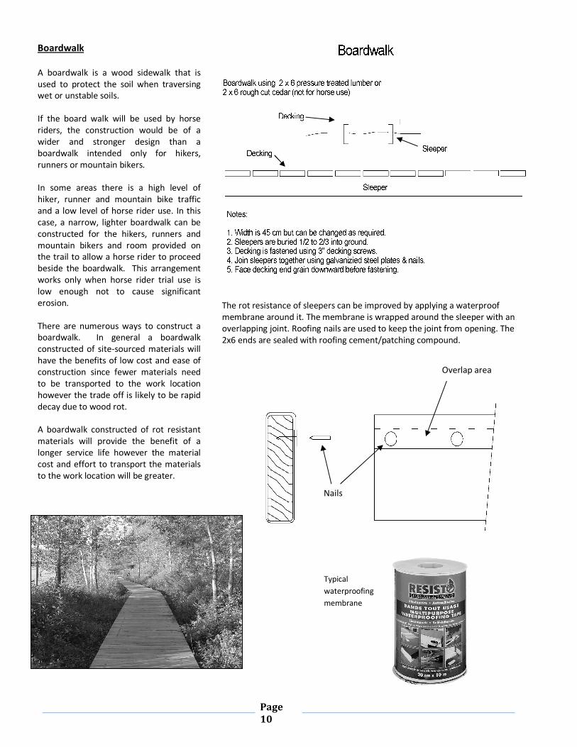
Causeway
A causeway is a turnpike without
the ditches. When constructed for
erosion control purposes, it is used
to raise the trail above a wet area.
To allow water flow through the
causeway, it should be constructed
as much as possible of rock and
stones.
A layer of landscape fabric is
placed above the base of rock and
stones. On top of the landscape
fabric, a trail bed of 5-10cm of
material is placed. The material
used for the trail bed above the
fabric depends of what is readily
available.
If available, larger rocks and stones
can be used to form the trail bed
surface with ideally a sand & soil
mixture used to fill the gaps
between the rocks or stones.
Page
10
Boardwalk
A boardwalk is a wood sidewalk that is
used to protect the soil when traversing
wet or unstable soils.
If the board walk will be used by horse
riders, the construction would be of a
wider and stronger design than a
boardwalk intended only for hikers,
runners or mountain bikers.
In some areas there is a high level of
hiker, runner and mountain bike traffic
and a low level of horse rider use. In this
case, a narrow, lighter boardwalk can be
constructed for the hikers, runners and
mountain bikers and room provided on
the trail to allow a horse rider to proceed
beside the boardwalk. This arrangement
works only when horse rider trial use is
low enough not to cause significant
erosion.
There are numerous ways to construct a
boardwalk. In general a boardwalk
constructed of site-sourced materials will
have the benefits of low cost and ease of
construction since fewer materials need
to be transported to the work location
however the trade off is likely to be rapid
decay due to wood rot.
A boardwalk constructed of rot resistant
materials will provide the benefit of a
longer service life however the material
cost and effort to transport the materials
to the work location will be greater.
The rot resistance of sleepers can be improved by applying a waterproof
membrane around it. The membrane is wrapped around the sleeper with an
overlapping joint. Roofing nails are used to keep the joint from opening. The
2x6 ends are sealed with roofing cement/patching compound.
Overlap area
Nails
Typical
waterproofing
membrane
Page
11
Selecting Wood for Boardwalks
Rough Cut or Milled Lumber
Rough cut lumber is un-milled lumber. It is slightly larger than milled lumber in both width
and thickness. As the name implies, rough cut lumber has a rougher finish. The larger size and
better traction provided by rough cut lumber is generally better for trail use. Lumber yards
and home improvement stores usually only stock milled lumber.
Pressure Treated Lumber
Pressure treated lumber is a good choice for trail use. It is usually only available as milled
lumber.
The amount of preservative in the wood after treatment is called the retention level. Wood
that will be exposed to the elements, but is not in contact with the ground should have a 0.25
(lb/ft3) retention. Wood in ground contact will require a minimum retention of 0.40 (lb/ft
3).
The preservative retention levels are printed on the quality mark tag that is stapled to the end
of the board.
Cedar
Cedar is also a good choice when in rough cut form. It is often available through lumber yards
that specialize in cedar. If rough cut cedar is not available in your area, use pressure treated
lumber instead.
Spruce & Pine
Untreated spruce and pine lumber when in contact with soil can be expected to have a high
rate of deterioration due to rot. These wood types are what most lumber yards and home
improvement stores have in stock for general purpose use.
Site Sourced Logs & Lumber
A common practise is to use site sourced logs as the purchase cost and difficulty in
transporting dimensional lumber to the work location can be a deterrent. A high rate of
deterioration can be expected as the wood is untreated and the species may not be ideal for
rot resistance. This is offset somewhat be using oversize logs as sleepers/mud sills. The larger
size of the logs will take longer to decay.
Sited sourced lumber is produced by cutting site sourced logs into planks. As with site sourced
logs, it often makes sense to cut logs into planks at the work location, however the skill and
equipment required is such that this guide does not include site produced lumber in the
design of boardwalks.