Embed Size (px)
Citation preview
Home A bout C opyright and Disc laimer C ontac t Us
Blog Entry
The LM324 Quad Op-Amp Line Follower Robot with Pulse WidthModulationJanuary 14, 2011 by rwb, under Robotics.
Designing a simple and yet functional Line Follower Robot (LFR) is always a fascinating and challenging subject
to be learned, the LFR actually could be implemented in many ways start from a simple two transistors to a
sophisticated PID (Proportional, Integrate and Differential) which take advantage of the programmable feature
of microcontroller to calculate the PID equation to successfully navigate the black track line on a white
background surface.
Designing a non microcontroller based LFR is quite challenging tasks as we need to limit the electronic
components numbers so the LFR will not too complicated to be built by most average robotics beginners or
electronic hobbyists, but at the same time we need to have a good speed control mechanism in order for the
LFR to navigate the black track line successfully. The microcontroller based design LFR in the other hand is a
popular choice because it reduces a number of electronic components significantly while still providing a flexible
programmable control to the LFR.
On this tutorial we are going to build yet another LFR using just the standard analog components easily found
on the market but use the same speed control method technique found in many good microcontroller based
Line Follower Robot design. As the result we could get a good precision analog line follower robot that
Custom Search
Search This Site
Search
Future Post
Pulse Width Modulation (PWM) is one ofthe important peripheral feature inmodern Microcontroller. PWM is used inmany embedded system application forcontrolling the power to the electricaldevice. On the next post we are goingto learn how to use this feature insimple and easy project.
Therefore don't miss it, stay tune on this
blog !
Recent Posts
Quick and Efficiently Wiring Your
ermicroblogMicrocontrollers and Electronics Project Blog
Ads by Google Circuit PWM Micro Robot PWM DC Motor Op Amp
Printed Circuit BoardC ompetitive pric ing with 24/7/365 Total C us tomer Satis fac tion.Q uotes
Fast - Cheap - PCBs$500 off PCBs.On-time shippingguaranteed!Expedites aSpecialty.www.4pcb.com
PADS PCB DesignSolutionIndustry LeadingPCB Design Tool,Download a PADS9.0 Demo Today!www.Mentor.com/PCB
Flex Circuits &RigidFlexFlex Circuits Designto AssemblyThinking Flex ThinkLenthorwww.Lenthor.com
Flex Circuit Mfg.Flex CircuitFabrication &Assembly RoHSTechnology, ISO9001:2000www.gcaero.com
Flexible CircuitsMfg.Competitive prices -quick deliveryPrototype thruProduction - ISOwww.FlexCircuitsInc.com
comparable to the microcontroller based Line Follower Robot design. On this tutorial you will also learn many
useful information of how to use the operational amplifier.
The Line Follower Robot
This Line Follower Robot basically use a Cadmium Sulphide (CdS) photocell sensor or known as Light Dependent
Resistor (LDR) and the high intensity blue Light Emitting Diode (LED) to illuminate the area under the photocell
sensor to sense the black track line and the DC motor speed control technique to navigate the black line track
as shown on this following picture:
The easy method to navigate the black track line is to turn ON and OFF the left or the right DC motor according
to the sensor reading (black turn OFF and white turn ON), but using this method will make the LFR to move in
zigzag way. By proportionally control both left and right DC motor speed according to the light intensity level
received by the photocell sensor (reflected back by the black track line) we could make the LFR easily navigate
this track. The common technique to control the motor speed efficiently is to use a pulse signal known as the
pulse width modulation or PWM for short.
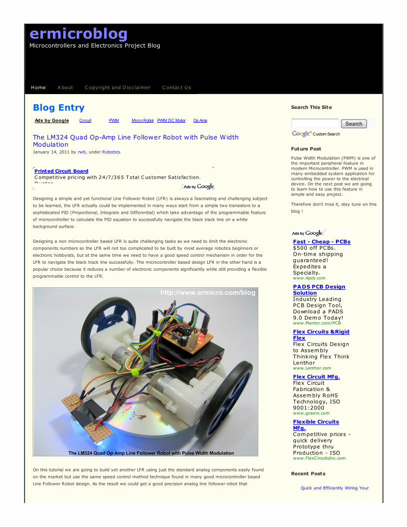
PWM basically is an ON and OFF pulse signal with a constant period or frequency. The proportion of pulse ON
time to the pulse period is called a “duty cycle” and it expressed in percentage. For example if the proportion of
pulse ON time is 50% to the total pulse period than we say that the PWM duty cycle is 50%. The PWM duty
cycle percentage is corresponding to the average power produced by the pulse signal; the lower percentage
produces less power than the higher percentage.
Prototype Circuit Board
The LM324 Quad Op-Amp Line
Follower Robot with Pulse Width
Modulation
The Year 2010 End Notes
Using Serial Peripheral Interface
(SPI) with Microchip PIC18 Families
Microcontroller
Integrating Wiznet W5100,
WIZ811MJ network module with
Atmel AVR Microcontroller
Stepping Into the 16-bit World with
the Microchip 16-bit
PIC24F16KA102 Family
Microcontroller
Building your own Simple Laser
Projector using the Microchip
PIC12F683 Microcontroller
Working with the Comparator
Circuit
Build Your Own Simple and Easy
PICAXE Microcontroller Based
Photovore Robot
Make your own Microcontroller
Printed Circuit Board (PCB) using
the Toner Transfer Method
The 2009 Year End Notes
PIC18 Pulse Width Modulation
(PWM) DC Motor Speed Controller
with the RPM Counter Project
PIC18 Microcontroller Analog to
Digital Converter with Microchip
C18 Compiler
Introduction to the Embedded
System with PICAXE Microcontroller
Transforming your AVR
Microcontroller to the I2C or TWI
Slave I/O Expander Project
Subscribe
Posts | Comments
Copyright
©

Therefore by changing the PWM duty cycles we could change the average voltage across the DC motor
terminals, this mean we could vary the DC motor speed just by changing the PWM duty cycle. Therefore to
make the LFR smoothly navigate the black track line, we have to adjust the PWM duty cycle according to the
photocell sensor reading. The brighter light intensity level received by sensor (sensor is on the white surface)
will result in higher PWM duty cycle percentage and the darker light intensity level (sensor is on the black line)
received by photocell sensor will result in lower PWM duty cycle percentage.
By converting each of the photocell sensor light intensity level reading to the corresponding voltage level we
could achieve this objective by using what is known as the Voltage Control Pulse Width Modulation principal.
Actually generating the PWM signal is easier with microcontroller instead of discrete components because all you
have to do is to program the microcontroller PWM peripheral to do the task. On this tutorial we will learn of how
to build this LFR with Voltage Control PWM using the same working principal found in many today’s modern
microcontroller but using just the analog electronic components.
Now let list down the necessary electronic and other supported components to build this awesome LFR:
1. Resistors: 220 (2), 1K (2), 15K (1), 33K (1), 47K (2), and 100K (1)
2. Trimports: 100K (2)
3. Light Dependent Resistor (2)
4. Capacitors: 47uF/16v (1) and 0.1uF (5)
5. Diodes: 1N4148 (2)
6. High Intensity 3 mm blue Light Emitting Diode (2)
7. Optional 5 mm auto flash RGB LED with 330 Ohm resistor for the power indicator
8. Transistors: BC639 (2)
9. IC: National Semiconductor LM324 Quad Operational Amplifier (1)
10. DC Motor: Solarbotics GM2 Geared DC motor with Wheel (2)
11. Prototype Board: 52 x 38 mm for main board and 50 x 15 mm for sensors
12. 3xAA Battery holder
13. CD/DVD ROM (2)
14. Plastic Beads and Paper Clip for the castor (the third wheel)
15. Bolt, Nuts, Double Tape and Standard Electrical Tape for the black line
The complete Line Follower Robot electronics schematic is shown on this following picture:
Recommended Books
Teach Yourself Electricityand Elect...
Stan Gibilisco
Best Price $14.80or Buy New $20.38
Privacy Information
Embedded CProgramming and the
Atmel...
Richard H. Barnett...
Best Price $78.11or Buy New $140.25
Privacy Information
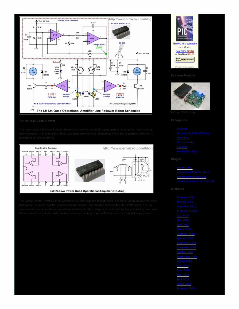
The Voltage Control PWM
The main brain of this Line Follower Robot is lay behind the LM324 quad operational amplifier from National
Semiconductor. The dual in line LM324 packages contains four identical op-amps and is specially designed to
operate as an analog device.
The voltage control PWM could be generated by first using the triangle signal generator which provide the basic
PWM pulse frequency and the necessary ramp voltage (rise and down) to produce the PWM signal. Next by
continuously comparing this ramp voltage according to the voltage level produced by the photocell sensor using
the comparator circuit we could produced the exact voltage control PWM as shown on this following picture.
The PIC Microcontrolle
John Morton
Best Price $26.56or Buy New $30.36
Privacy Information
Feature Product
PICJazz 20PIN Board
Categories
Blognote
Development Board News
Electronics
Microcontroller
Robotics
Yet Another Tips
Blogroll
ermicro shop
ermicroblog Amazon Store
ermicroblog on YouTube
ermicroblog video on Metacafe
Archives
February 2011
January 2011
December 2010
September 2010
July 2010
May 2010
April 2010
March 2010
February 2010
January 2010
December 2009
November 2009
October 2009
September 2009
August 2009
July 2009
June 2009
May 2009
April 2009
March 2009
February 2009
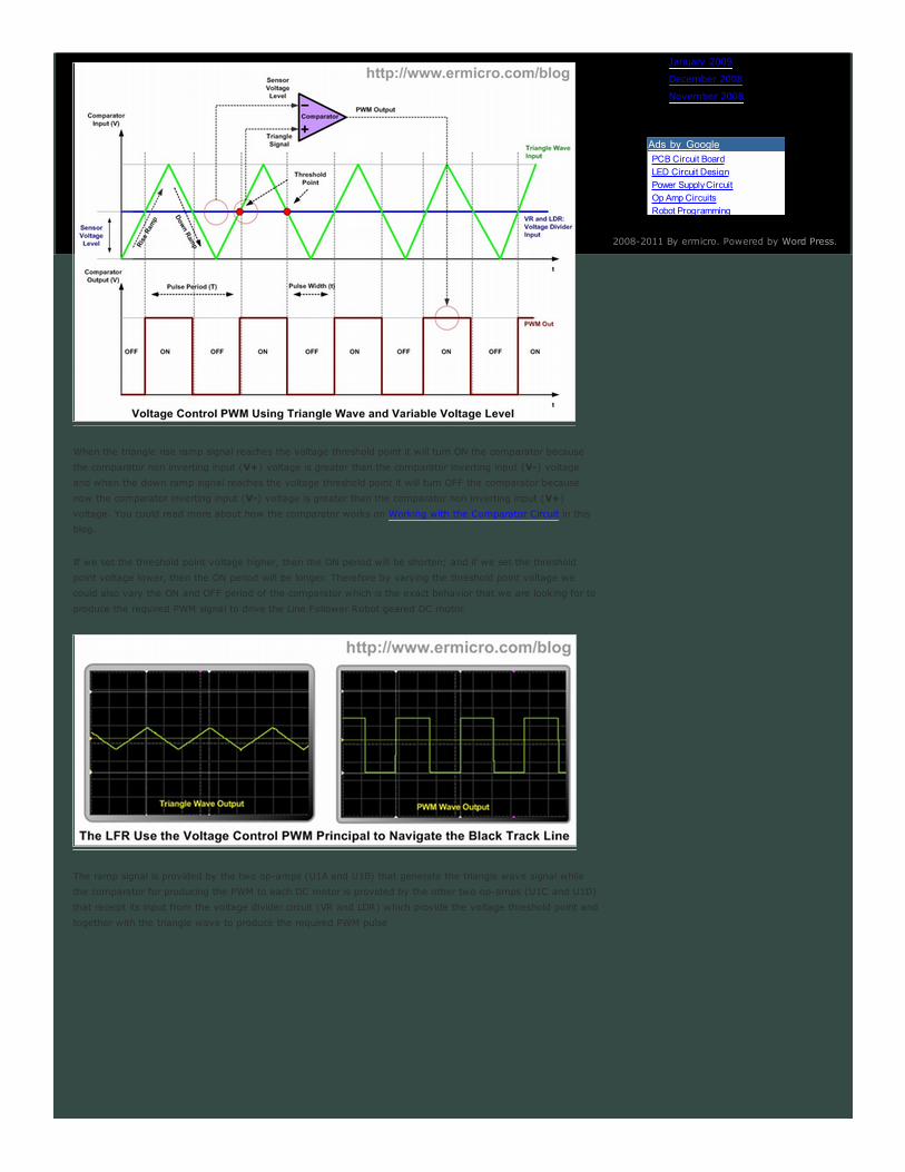
When the triangle rise ramp signal reaches the voltage threshold point it will turn ON the comparator because
the comparator non inverting input (V+) voltage is greater than the comparator inverting input (V-) voltage
and when the down ramp signal reaches the voltage threshold point it will turn OFF the comparator because
now the comparator inverting input (V-) voltage is greater than the comparator non inverting input (V+)
voltage. You could read more about how the comparator works on Working with the Comparator Circuit in this
blog.
If we set the threshold point voltage higher, then the ON period will be shorten; and if we set the threshold
point voltage lower, then the ON period will be longer. Therefore by varying the threshold point voltage we
could also vary the ON and OFF period of the comparator which is the exact behavior that we are looking for to
produce the required PWM signal to drive the Line Follower Robot geared DC motor.
The ramp signal is provided by the two op-amps (U1A and U1B) that generate the triangle wave signal while
the comparator for producing the PWM to each DC motor is provided by the other two op-amps (U1C and U1D)
that receipt its input from the voltage divider circuit (VR and LDR) which provide the voltage threshold point and
together with the triangle wave to produce the required PWM pulse
January 2009
December 2008
November 2008
2008-2011 By ermicro. Powered by Word Press.
Ads by Google PCB Circuit Board
LED Circuit Design
Power Supply Circuit
Op Amp Circuits
Robot Programming
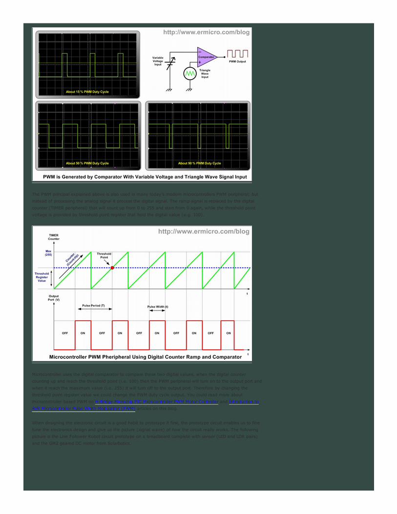
The PWM principal explained above is also used in many today’s modern microcontrollers PWM peripheral; but
instead of processing the analog signal it process the digital signal. The ramp signal is replaced by the digital
counter (TIMER peripheral) that will count up from 0 to 255 and start from 0 again, while the threshold point
voltage is provided by threshold point register that hold the digital value (e.g. 100).
Microcontroller uses the digital comparator to compare these two digital values, when the digital counter
counting up and reach the threshold point (i.e. 100) then the PWM peripheral will turn on to the output port and
when it reach the maximum value (i.e. 255) it will turn off to the output port. Therefore by changing the
threshold point register value we could change the PWM duty cycle output. You could read more about
microcontroller based PWM on H-Bridge Microchip PIC Microcontroller PWM Motor Controller and Introduction to
AVR Microcontroller Pulse Width Modulation (PWM) articles on this blog.
When designing the electronic circuit is a good habit to prototype it first, the prototype circuit enables us to fine
tune the electronics design and give us the picture (signal wave) of how the circuit really works. The following
picture is the Line Follower Robot circuit prototype on a breadboard complete with sensor (LED and LDR pairs)
and the GM2 geared DC motor from Solarbotics.
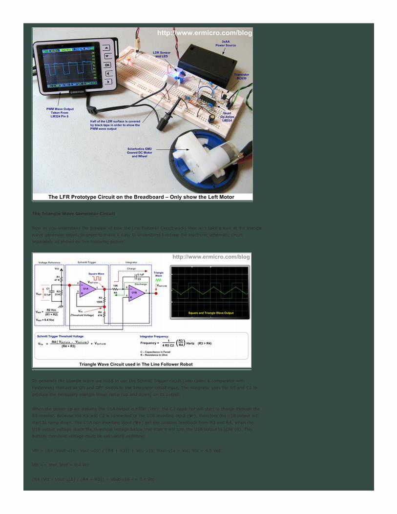
The Triangle Wave Generator Circuit
Now as you understand the principal of how the Line Follower Circuit works than let’s take a look at the triangle
wave generator circuit. In order to make it easy to understand I redraw the electronic schematic circuit
separately as shown on this following picture:
To generate the triangle wave we need to use the Schmitt Trigger circuit (also called a comparator with
hysteresis) that act as ON and OFF switch to the Integrator circuit input. The integrator uses the R5 and C2 to
produce the necessary triangle linear ramp (up and down) on its output.
When the power up we assume the U1A output is HIGH (Vcc); the C2 capacitor will start to charge through the
R5 resistor. Because the R5 and C2 is connected to the U1B inverting input (V-), therefore the U1B output will
start to ramp down. The U1A non inverting input (V+) get the positive feedback from R3 and R4, when the
U1B output voltage reach the threshold voltage below Vref than it will turn the U1A output to LOW (0). This
bottom threshold voltage could be calculated as follow:
Vth = (R4 (Vout-u1a - Vout-u1b) / (R4 + R3)) + Vou-u1b; Vout-u1a = Vcc; Vcc = 4.5 Volt
Vth <= Vref, Vref = 0.4 Vcc
(R4 (Vcc - Vout-u1b) / (R4 + R3)) + Vout-u1b <= 0.4 Vcc
Now putting all the resistors value then we will get this following result:
(47 (Vcc - Vout-u1b)/ 147) + Vout-u1b <= 0.4 Vcc
1.4 - 0.3 Vout-u1b + Vout-u1b <= 1.8
Vout-u1b <= 0.6 Volt
Therefore the U1B output will ramp down to about 0.6 volt than the U1A output will turn OFF. Next the C2
capacitor will discharge through R5 and the UA1B output will start to ramp up and it start to increase the voltage
across the R4 (Vth - threshold voltage) until the Vth voltage above the Vref voltage then the U1A output will
turn to HIGH and the whole cycle will repeat again. This upper threshold voltage could be calculated as follow:
Vth = (R4 (Vout-u1a - Vout-u1b) / (R4 + R3)) + Vou-u1b; Vout-u1a = 0; Vcc = 4.5 Volt
Vth >= Vref; Vref = 0.4 Vcc
(R4 (- Vout-u1b) / (R4 + R3)) + Vout-u1b >= 0.4 Vcc
Now putting all the resistors value then we will get this following result:
(47 (- Vout-u1b)/ 147) + Vout-u1b >= 0.4 Vcc
- 0.3 Vout-u1b + Vout-u1b >= 1.8
Vout-u1b >= 2.6 Volt
Therefore the triangle voltage will ramp up from 0.6 volt to 2.6 volt then ramp down to 0.6 volt repeatedly. The
frequency of the triangle wave could be calculated as follow:
Frequency = (1 / (4 x R5 x C2)) x (R3/R4) Hertz
Now putting all the resistors and capacitor value then we will get this following result:
Frequency = (1 / (4 x 15,000 x 0.0000001)) x (100,000/47,000) = 354.61 Hz
As you might guess the actual frequency measured on this Line Follower Robot prototype circuit above is about
292 Hz, this is due to the electronic components tolerance value (resistors and capacitors). Therefore if you
want to have the exact frequency you could put a 100K trimport in series with R5 resistors. The voltage divider
R1 and R2 provide the voltage reference (DC bias voltage) to both U1A and U1B op-amps.
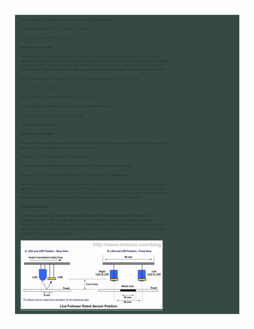
The Sensor Circuit
As mention above this Line Follower Robot take advantage of the photo-resistor (CdS) known as Light
Dependent Resistor (LDR). The LDR will decreases its resistance in the presence of light and increase its
resistance in the dark. The region under the LDR is illuminate with a high intensity blue LED, the white surface
will reflect most of the light to the LDR surface while the black track line will absorb most of the light, therefore
less light will reflect to the LDR surface.
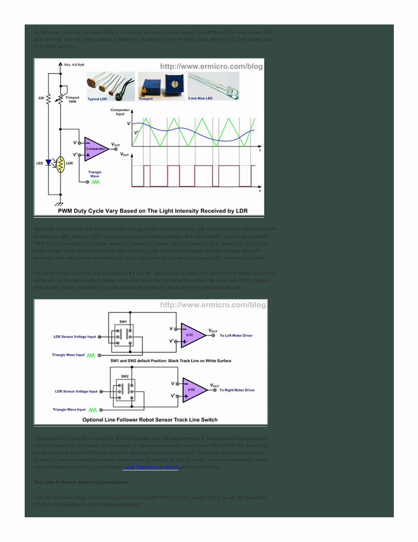
As the robot move on the black track line the LDR will continuously capture the reflected light and convert this
light intensity into the corresponding voltage and feeding it to the inverting input (V-) of U1C (left sensor) and
U1D (right sensor).
The 100K trimport and LDR basically is the voltage divider circuit when the LDR detect the black track line it will
receive less light intensity (LDR resistance increase) and the voltage (V-) will increase; this will decrease the
PWM duty cycle output and as the result the geared DC motor will turn slowly or stop. When the LDR on the
white surface it will receive maximum light intensity (LDR resistance decrease) and the voltage (V-) will
decrease; this will increase the PWM duty cycle output and as the result the geared DC motor will turn fast.
You could simply exchange the comparator V+ and V- input source to make the Line Follower Robot detect the
white line on the black surface instead of normal black line on the white surface. By using two DPDT (Double
Pole Double Throw) switches you could achieve this behavior as shown on this following picture:
The geared DC motor driver uses the BC639 transistor and the base terminal is connected to the comparator
output through the 1K resistor. The transistor is operated as a switch which turns ON and OFF the geared DC
motor according to the PWM pulse current it received from the comparator. The 0.1uF capacitor across the
geared DC motor’s terminal is used to reduce noise generated by the DC motor. For more information about
using transistor as switch you could read Using Transistor as Switch article on this blog.
The Line Follower Robot Construction
The Line Follower Robot construction could be constructed freely but the easiest one is to use the discarded
CD/DVD ROM as shown on this following pictures:
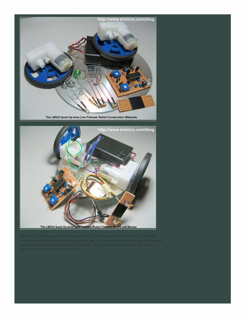
I glue the two CDROM together in order to make more room and attached the two DC motors, 3xAA battery
holder, main board and sensor board using the double tape. The sensor sensitivities and the Line Follower Robot
speed could be controlled by adjusting the 100K trimport. After putting all the parts together now is time to
watch how this nice Line Follower Robot in action:

30.01.11 #1
31.01.11 #2
The Final Thought
As you’ve seen from the demo video above this Line Follower Robot design is capable to handle and smoothly
navigate a quite complex black track line. This prove that a good analog Line Follower Robot design sometimes
could outperform many microcontrollers based Line Follower Robot.
Building the Line Follower Robot (LFR) is one of my favorite projects as I enjoy designing and making this kind
of robot, it also gives much joy and fun to my kids as well. I hope this project will give you as much joy as I
did; building, watching, and playing with this analog Line Follower Robot.
Bookmarks and Share
Related Posts
Build Your Own Transistor Based Mobile Line Follower Robot (LFR) – First Part
Behavior Based Artificial Intelligent Mobile Robot with Sharp GP2D120 Distance Measuring Sensor - BRAM
Part 2
Building BRAM your first Autonomous Mobile Robot using Microchip PIC Microcontroller – Part 1
Seven Segment Display Thermometer with PIC Microcontroller
Basic Servo Motor Controlling with Microchip PIC Microcontroller
28 Responses to “The LM324 Quad Op-Amp Line Follower Robot with Pulse Width Modulation”
Comment by UJ.
Very nice article. Just one question, how did you get the formula
for the integrator frequency?
Thank you for the good work.
Prototype PCB Assembly24hr Full-service, IPC C lass 2 & 3 New cus tomer discountwww.screamingcircuits.com

05.02.11 #3
05.02.11 #4
06.02.11 #5
06.02.11 #6
06.02.11 #7
06.02.11 #8
Comment by rwb.
Thanks, Actually you could find this formula in any good Op-Amps
textbook. Here is the simple explanation:
The half of triangle ramp slope time (t):
t = 2.R5.C2 . (R4/(R3 + R4))
Therefore for one period (T = 2t):
T = 4.R5.C2 . (R4/(R3 + R4))
f (Frequency) = 1/T, and assume R3 > R4, then we could get
this following equation:
f = 1 / (4.R5.C2) . (R3/R4)
Comment by ankur619.
thanks a lot for this tutorial sir…it helped me a lot…
Sir can we use any ordinary geared motor for this project
Comment by rwb.
Sure, you can use any low RPM geared DC motor.
Comment by jp1238.
sir,can v use an input power of 12 volt.
Comment by rwb.
This LFR circuit is designed to work within 4.5 to 5 volt.
Comment by jp1238.
sir then its movement will be very slow isnt it. how to increase
the speed.i bought a motor of 200 rpm dc 6volt, will that
work???..
Comment by rwb.
If you compare with “Build Your Own Microcontroller Based PID
Control Line Follower Robot (LFR) (Second Part)” project; yes it
slower but if you compare with “Build Your Own Transistor Based
Mobile Line Follower Robot (LFR) First Part” project; this LFR is
faster. Because in this project I used a simple sensor such as LDR
and control for tracking the black line, therefore you could not get
a “fast” LFR; I would say this LFR speed is moderate.
Anyway you should experiment with your motor and adjust the
geared DC motor speed with the trimport (i.e. VR1 and VR2). My
suggestion, don’t afraid to experiment with electronics, this is how
you gain your experiences and knowledge.

07.02.11 #9
08.02.11 #10
08.02.11 #11
08.02.11 #12
09.02.11 #13
09.02.11 #14
09.02.11 #15
14.02.11 #16
Comment by jp1238.
thank you sir..ur tutor is more helpfull to me..i need more of this
stuffs..if you have any new electronics projects please sent it to
me it will be more helpfull to me,as ur explanation is more
understandable to me than others.My email id is
[email protected]…these projects helps me a lot…
Comment by j-pal.
what was the cost to build this robot?
Comment by rwb.
The most expensive parts is the DC geared motor, it will cost
about USD 20 for two motors with wheels. The LDR, Resistors,
Trimports, LEDs, Transistors, LM324 Quad Op-Amp, Cables,
Prototype Boards and 3AA battery holder are less then USD 15.
Therefore the total cost to build this LFR should be less than USD
40.
Comment by jyothinath.
Can u please give a circuit having “obstacle sensor ” coupled
along with this line follower robot..
Comment by rwb.
Currently this circuit is mainly designed as LFR without the
obstacle sensor to keep it simple.
Comment by jyothinath.
ok..but when we place some aditional features like obstacle
sensor , will this be able to move smoothly ?
Comment by rwb.
Its depend on the robot design e.g. the priority level that you
assigned to the line sensor and the obstacle sensors. You could
read more regarding this matter on “Building BRAM your first
Autonomous Mobile Robot using Microchip PIC Microcontroller –
Part 1” and “Behavior Based Artificial Intelligent Mobile Robot with
Sharp GP2D120 Distance Measuring Sensor - BRAM Part 2”
articles.
Comment by ankur619.
sir..I Can’t find the BC639 transistor in the local market..
Please suggest any possibe substitutes for this transistor..
Thank u

14.02.11 #17
17.02.11 #18
17.02.11 #19
17.02.11 #20
17.02.11 #21
18.02.11 #22
18.02.11 #23
18.02.11 #24
Comment by rwb.
You could replace it with 2N2222A
Comment by Sangeeth.
Sir,we tried this circuit,but the sensor part did not work wit a
supply of 5v.sir,what’s d rpm of the dc geared motor using
here??pls reply…
Comment by ankur619.
sir..i have connected all the components as the circuit mentioned
above..but there is no deflection in the motor..
The motors,leds and the ldrs are allright..but still no deflection…
Please help me sir
i would be really grateful to u
Comment by rwb.
@Sangeeth, @ankur619: You need to recheck and recheck
again all of your electronic components connection, make sure
you follow the exact circuit diagram above. In this project I used
Solarbotics GM2 geared DC motor.
Comment by Sangeeth.
Thanks sir 4 d rply.i checkd d ckt again nd again.we got d motors
working(usd toy motors)bt d sensor part shows no o/p at al.d
led’s didnt glow..can we use ny other motor other than
solarbotics,as it s nt available in kerala..pls do rply sir
Comment by ankur619.
sir…my leds are glowing but the motor are nt showing any
deflection..i think there is some mistake in the..U1A and U1B part.
I guess the polarity should be interchanged which is shown in the
ckt diagram you mentioned above
Comment by ankur619.
I am using a trimpot which has 3 terminals..so which 2 terminals
should i use to connect in this circuit..plz help me sir
Comment by rwb.
@Sangeeth: As long as it has the same specification with
Solarbotics GM2 geared DC motor and you could always
experiment with other geared DC motor.
@ankur619: Follow the electronic schematic! For the trimport
you could use three terminals as shown on the schematic (an
arrow is for the center terminal) or just two terminals i.e. the

19.02.11 #25
19.02.11 #26
19.02.11 #27
19.02.11 #28
center terminal and one of the other two terminals.
Comment by Sangeeth.
Thanx 4 d rply sir.ny idea abt y d sensor part nt workng??should
we use dual supply or sumting??
Comment by rwb.
Make sure you connect all the electronic parts correctly i.e. LED
and LDR
Comment by ankur619.
i have one question…….for eg we have a straight black line over a
white surface and another black line which is intersecting the first
black line at 90 degree….will this robot be able to cros over the
crossed path…..or it will stop? please help me with the robot
which can perform this task…….
Comment by rwb.
Yes, you could watch the LFR crossing the black line on the video
link above.
Leave a Comment
You must be logged in to post a comment.

![A High-Speed 64-Bit Binary Comparator€¦ · A high-speed 64-bit binary comparator 39 | Page III. EXISTING 64-BIT BINARY COMPARATOR DESIGN 64-bit comparator in reference [8], [9],](https://img.pdfslide.us/doc/110x75/5eac1a458d19873e777698b4/a-high-speed-64-bit-binary-comparator-a-high-speed-64-bit-binary-comparator-39-.jpg)