Embed Size (px)
Citation preview
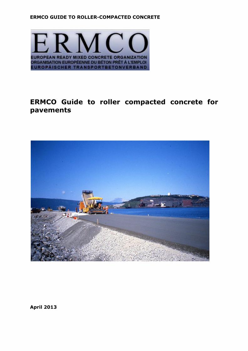
ERMCO GUIDE TO ROLLER-COMPACTED CONCRETE
ERMCO Guide to roller compacted concrete for
pavements
April 2013

ERMCO GUIDE TO ROLLER-COMPACTED CONCRETE
Photograph on cover page: Construction of a roller-compacted concrete road in Norway
The recommendations contained herein are intended only as a general guide and, before
being used in connection with any specific application, they should be reviewed with
regard to the full circumstances of such use. Although every care has been taken in the
preparation of this Guide, no liability for negligence or otherwise can be accepted by
ERMCO, its members, its servants or agents.
ERMCO publications are subject to revision from time to time and readers should ensure
that they are in possession of the latest version.
ERMCO GUIDE TO ROLLER-COMPACTED CONCRETE
1
Contents
Summary
1. Introduction
2. Brief history of use 3. Pavement design 4. Durability and surface characteristics
4.1 Freeze-thaw resistance 4.2 Abrasion resistance
4.3 Surface characteristics 5. Materials, mix proportioning, production and transporting RCC 5.1 Materials
5.2 Mix proportioning 5.3 Production
5.4 Transportation to site 6. Construction of RCC pavements
6.1 General procedures
6.2 Unrestrained edges 6.3 Contraction joints
6.4 Curing 6.5 Early opening strength 6.6 Trial section
7. Conformity of RCC by the concrete producer 8. In-situ testing of RCC
9. Conclusions 10. References
10.1 Standards 10.2 Other references
Annex A: Model specification for an RCC pavement A.1 General requirements
A.2 Normative references A.3 Roller-compacted concrete
A.3.1 Additional requirements for constituents
A.3.2 Initial testing of RCC A.3.3 Conformity of compressive strength
A.4 Construction requirements A.4.1 Preparation of the sub-grade/sub-base A.4.2 Trial section (where specified in the project specification)
A.4.3 Transport to site A.4.4 Placing, compaction and conformity of in-situ plastic density
A.4.5 Joints A.4.6 Curing and protection from early trafficking A.4.7 Tolerances for industrial pavements
.

ERMCO GUIDE TO ROLLER-COMPACTED CONCRETE
2
Summary
Roller-compacted concrete (RCC) is a cement or cement plus type II addition hydraulically-bound material used for pavements and other applications. RCC
pavements are a sustainable construction solution. The material is placed with asphalt paving equipment, but needs further compaction by rollers. The surface may be left exposed for low speed or heavy-duty applications, or a thin wearing
surface may be applied where improved high speed skid resistance is required. RCC provides a cost effective solution for pavements where rapid construction is
needed and reduced maintenance is required.
This Guide provides an introduction to RCC pavements and a model specification for use in Europe. It is not intended to be ‘chapter and verse’ on RCC, but an
introduction to the subject and sufficient information to get started.
RCC has other uses such as for dam construction, but these applications are not
covered in this Guide.
1. Introduction
Roller-compacted concretes (RCC) are concretes that are capable of being compacted immediately after placing by dead-weight or vibrating rollers. The constituents are the same as for conventional concretes but the mix proportions
differ in that the aggregate grading and content has to be such that the RCC can immediately take load. RCC may be used to provide the base and wearing layers
of a pavement.
RCC is a hydraulically-bound material with compressive and flexural strengths in the range associated with structural concrete (i.e. a compressive strength
C30/37). Conventional concrete pavements are designed as rigid pavements whilst asphalt pavements are designed as flexible pavements and therefore RCC
has the structural design approach of conventional concrete pavements and the construction approach of asphalt.
It is a zero-slump material that has to be compacted by roller to achieve the
required density. It differs from conventional hydraulically-bound materials in that it can provide the wearing surface to traffic, and it is a material that does
not fall within the current scope of the European Standard for Hydraulically bound mixtures, EN 14227-1:2004, or into the European Standard for Concrete, EN 206-1 without utilizing the specification of ‘Other technical requirements’.
RCC is a rapid form of construction, which is an advantage over the slower pavement-quality concrete construction. Trafficking at much earlier ages than
with conventional pavement concrete is possible due to its rapid gain of strength.
RCC’s durability comes from its low water/cement ratio, although this is not a
specification requirement, and its high density. Some of its earliest uses were for heavy-duty industrial pavements where strength and durability were the prime
consideration. As it is compacted by roller, the surface is smooth and dense and suitable for parking, storage and road pavements where the traffic speeds are
relatively low if it is to provide the running surface. For high speed road application, one solution is to overlay the RCC with an additional asphalt surface

ERMCO GUIDE TO ROLLER-COMPACTED CONCRETE
3
course. Overlaying with an asphalt surface course provides a means of achieving the necessary high speed skid resistance and surface regularity. Another solution
that is used in the USA is to diamond grind the areas that do not initially conform to the surface tolerance requirements and groove the surface to provide
high speed skid resistance.
RCC is a sustainable solution where the embodied carbon dioxide and the sustainability of the resources used may be lower than alternative pavement
solutions of equivalent performance. RCC may incorporate recycled concrete aggregates and this is particularly sustainable if they come from the pavement
being replaced.
As outlined in the following section, the use of RCC since 1970 has increased significantly during the last 20 years and much of the experience gained during
this period is available in various publications [1, 2 and 3]. In particular the ‘Guide to roller-compacted concrete pavements’ [1] is recommended as an
excellent source of information.
2. Brief history of use
While some early examples of RCC dating back to the 1930’s and 1940’s have been reported [1], the first widespread use of RCC was in the 1970’s by the Canadian logging industry when the new land-based log sorting methods
needed a strong, fast but economic paving system that could take the massive loads and handling equipment. RCC provided the solution. As appearance was
not in this case a primary concern, they did not even provide joints but let the concrete crack, and this made RCC an even more economic solution.
From the 1980’s onwards the use of RCC has increased for technical and economical reasons. In the USA, data from Pittman [4] showed that in 1998 about 2.5 million square metres of RCC was constructed and by 2008 this had
increased to 8 million m2, i.e. more than tripled in ten years.
Some major applications of RCC today are:
● commercial parking areas;
● industrial storage and parking pavements;
● waste transfer areas;
● container port and dock storage areas;
● truck and freight terminals;
● military applications where speed of construction is essential;
● low volume and urban and rural roads and hardshoulders;
● aircraft parking areas (with thin asphalt wearing layer to avoid any
potential risk of a loose particle entering a jet engine).
Two recent examples of RCC construction are shown in Figure 1 and Figure 2.

ERMCO GUIDE TO ROLLER-COMPACTED CONCRETE
4
Figure 1: Tattershall Quarry Haul road, UK
This is a private heavy duty access road where RCC was
preferred because of the speed of construction. Heavy duty machinery can traffic the road
almost immediately after construction.
(by courtesy of CEMEX UK Materials)
Figure 2: RCC being placed at Tilbury docks, London.
(by courtesy of Aggregate Industries)
RCC was selected for Tilbury docks as it provided a fast and cost-effective solution for creating heavy duty pavement capable of taking the wear and tear
associated with constant unloading and loading of ships.
3. Pavement design
As with conventional concrete pavements, RCC is designed as a rigid pavement. In common with other rigid pavements, the inputs to the design process are the bearing capacity of the sub-grade, the type and thickness of sub-base, the
flexural tensile strength of the RCC and the type and frequency of loading (expressed as millions of standard axles over the design life). The output is the
thickness of slab required.
Several methods of design are available and reference [1] gives further details. In some cases software programmes are available for downloading. For example
you can download Streetpave 12 from http://www.pavement.com/streetpave/

ERMCO GUIDE TO ROLLER-COMPACTED CONCRETE
5
for a 30 day free trial period. Concrete Society Report 66 [2] provides thickness design charts (in metric) for external paving with RCC.
An input to the design process is the flexural tensile strength of the concrete and this is usually derived from the compressive strength class and is specified in the
project specification. Table 1 gives the EN 1992-1-1 relationship between mean flexural tensile strength and compressive strength class.
The relationship given in Table 1 is based on the mean compressive strength
(fcm) being 8 N/mm2 cylinder strength or 10 N/mm2 cube strength higher than the specified characteristic strengths (fck,cy and fck, cube). Concrete Society
Technical Report 66 [2] uses a slightly lower (safer) margin of 7 N/mm2 cube strength.
There is variability in the relationship between flexural tensile strength and
compressive strength, but it is normal to use a standardized fixed relationship such as those described previously. It is also possible during the initial testing to
determine the actual relationship between flexural strength and compressive strength for the proposed mix.
Table 1: EN1992-1-1 relationship between compressive strength class and
mean flexural tensile strength
Compressive strength class Mean flexural tensile strength, N/mm2
C25/30 3,8
C30/37 4,3
C35/45 4,8
C40/50 5,3
C45/55 5,7
C50/60 6,1
C55/67 6,3
C60/75 6,5
Except where random cracking is acceptable, contraction joint locations should
be detailed on the drawings as for normal pavement design. The need for contraction joints in all circumstances, and their spacing, are still topics where there is no consensus.
Contraction joints in RCC do not contain dowel bars. See 6.3 for information on the way contraction joints are formed. If large areas are planned, it may also be
necessary to provide expansion joints, particularly if the concrete is to be placed during cold weather and this will be followed by high summer temperatures. The details of expansion joints are similar to those used in pavement quality
concrete.
4. Durability and surface characteristics
4.1 Freeze-thaw resistance
RCC is rarely air-entrained and experience has shown that air entrainment is not
normally needed, even in conditions where there is the potential for freeze-thaw damage. There are some exceptions to this generalisation. Firstly the aggregates

ERMCO GUIDE TO ROLLER-COMPACTED CONCRETE
6
have to be freeze-thaw resisting and this is why the model specification (Annex A) includes this requirement. Then there has to be sufficient fine material to give
a closed structure and the RCC has to be compacted as required by the specification so that the potential resistance is achieved in practice.
RCC, like concrete block paving, achieves much of its freeze-thaw resistance by the presence of entrapped air voids of similar size to entrained air voids. Reference [1] summarizes the North American experience with the freeze-thaw
resistance of RCC.
Where there is concern on whether the RCC will provide adequate freeze-thaw
resistance, freeze-thaw testing is recommended as part of the initial testing of the RCC mix. However the criteria applied to many freeze-thaw tests are harsh and may fail RCC (and other concretes) that have performed adequately in
practice.
4.2 Abrasion resistance
In some industrial uses, the RCC is required to have a high abrasion resistance.
The requirement for the coarse aggregate to have a Los Angeles category LA40 for aggregate interlock at the contraction joints also ensures that the aggregate will have a high abrasion resistance. It is rarely necessary to specify aggregate
with a higher crushing resistance.
To achieve a high abrasion resistance, a high compressive strength class is often
specified. The compressive strength class that is specified should be at least equal to that recommended in provisions valid in the place of use for abrasion resistance. If the compressive strength class needed for abrasion resistance is
higher than the compressive strength class used in the initial pavement design, it is recommended that the pavement design is reviewed as this may allow a
thinner RCC pavement and consequential cost savings.
4.3 Surface characteristics
Figure 3 show the typical surface finish that is achieved. The surface finish will depend upon the mix proportioning. With such dry concretes, brushed surface
finishes such as those obtained with pavement quality concrete are not possible. Consequently it is not possible to get the same skid resistance with high speed
traffic, therefore when RCC is to provide the finished surface, it should be limited to parking areas and roads with only low speed traffic, unless subsequent surface treatment, such as diamond grinding, is carried out.
The required surface regularity is governed by the end use, and the requirement and method of testing should be specified in the contract documents.

ERMCO GUIDE TO ROLLER-COMPACTED CONCRETE
7
Figure 3: Typical surface finish with 20mm (left) and 10 mm (right) maximum aggregate size
(by courtesy of CEMEX UK Materials)
5. Materials, mix proportioning, production and
transporting RCC
5.1 Materials
Because of the method of placing and compaction, RCC requires a similar aggregate grading to asphalt concrete mixtures and hydraulically-bound sub-bases. The importance of getting the right grading is emphasized in many
documents [1, 5, 6, 7]. Aggregates comprise a higher proportion in RCC when compared with normal concretes, typically up to 85% of the volume of RCC and
the correct selection and grading of aggregates is key to having a successful RCC mixture. The RCC must be compactable and capable of achieving the required density with the planned compaction procedure. Aggregate strength is
also important to ensure that it does not disintegrate during compaction and is capable of providing aggregate interlock at the contraction joints. Excessively
flaky aggregates are unsuitable for RCC and this is why the specification given in Annex A contains a limit on the flakiness index.
It is normal to produce RCC using cements conforming to EN 197-1. Sometimes
additions within the scope of EN 206 are used but not under the k-value concept, as there is no specified maximum w/c ratio or minimum cement
content for RCC.
The reactivity with respect to alkali-aggregate reaction should be known and some specifiers may set lower total alkali limits on RCC if additional alkalis may
enter the concrete during the service life, e.g. from de-icing salts. In many places in Europe, the aggregates will also have to be freeze-thaw resisting. The
requirements in the provisions valid in the place of use for aggregates in concrete exposed to the XF3 or XF4 environments (defined in EN206) apply to RCC mixtures.
ERMCO GUIDE TO ROLLER-COMPACTED CONCRETE
8
5.2 Mix proportioning
The cement and addition, if any, have to achieve the required compressive strength and there must be sufficient binder to coat the aggregate particles and
give a closed structure. Too much paste causes the RCC to form a wave in front of the roller wheel. Consequently there is a need to find the cement content that
is sufficient to give a closed structure, but is not excessive. North American experience [1] indicates that to meet this requirement the cement content of RCC is lower than with conventional pavement concrete.
There are several methods of mix proportioning [1] and the soil compaction method is the most commonly used at present. In the future, more use is likely
to be made of “particle packing” models [8, 9] to determine the maximum dry density as this saves on laboratory time and quickly allows a range of materials
to be assessed. The soil compaction model is similar in approach to the design of hydraulically bound materials and for soil stabilization; once the optimum grading and binder contents are determined, the mixture is tested at different
moisture contents to determine the moisture content that gives the maximum dry density. For practical reasons the plastic density is also recorded as this is
measured when checking if the RCC has been adequately compacted.
The required compressive characteristic strength (including the margin) needs to be achieved at the design plastic density. If it is not being achieved, it may be
necessary to do one or more of the following:
● use water-reducing admixtures to lower the w/c ratio;
● if an addition is being used, increase the proportion of cement in relation to the addition;
● increase the cement content.
Experience has indicated that batching at a slightly higher moisture content than that needed to achieve the maximum dry density gives a better finish. This
increase may be up to 0.5% but it will depend upon the travel time and weather conditions.
5.3 Production
RCC can be produced in any ready-mixed concrete plant. The ideal fixed plant
situation is mixing in a central mixer and discharging directly into non-agitating vehicles. As the volumes of RCC can be large, the plant should have sufficient
capacity to supply at the rate needed and it is good practice to have a back-up plant available in case of a plant breakdown. As with pavement quality concrete, on large sites it is often the practice for the ready-mixed company to set up a
plant on site and use the local plant as back-up.
5.4 Transportation to site
RCC is normally transported to site in non-agitating vehicles, e.g. tipper trucks
and the truck should be sheeted to prevent drying or water gain from rain. Each delivery vehicle should be checked to ensure that the concrete is fully

ERMCO GUIDE TO ROLLER-COMPACTED CONCRETE
9
discharged. If RCC is left in the truck, it may get discharged in a later delivery and cause a localised problem in the pavement.
A simple subjective test for each load of RCC is the ‘snowball test’. This is a useful way to identify loads that are too dry or too wet. Wearing waterproof
gloves, try making a ball of concrete. If you get a stable ball with no fine mortar on the gloves, the RCC is ‘about right’. If you cannot form a ball or just have dry material, the RCC is too dry. If you cannot form a ball and have an unstable
wet material, the RCC is too wet.
The supply rate should be determined to ensure a continual supply to the paving
machine.
6. Construction of RCC pavements
6.1 General procedures
RCC should not be placed on standing water or during heavy rainfall. To
minimise the risk of damage due to freezing at an early age, RCC should not be
placed when the ambient temperature is less than 5C.
RCC is usually placed with an asphalt paving machine. Conventional asphalt
paving machines compact the RCC by either tamping or vibration. Combination paving machines compact the RCC by a combination of tamping and vibration.
As conventional machines achieve about 80% to 85% of the design density and combination machines > 90% of the design density, further rolling is essential. Combination machines are needed to place thick layers of RCC but, when these
are not available, conventional paving machines are used to place the RCC in two 100mm to 150mm layers instead of one thick layer.
Prior to placing it is essential to develop a rolling pattern that leads to uniform compaction of the RCC so that the edges are compacted as fully as the centre of the lane. An example rolling procedure for a 100mm to 150mm layer of RCC
after it has left the asphalt paver is:
— light rolling with a 4 tonne roller;
— forming of contraction joints;
— rolling with a 10 tonne pneumatic tyre roller;
— rolling with a 10 tonne dead-weight roller.
Typically with thicker layers, the first two stages would be the same, but then the procedure is:
— compacting with a 10 tonne vibrating roller;
— rolling with a 10 tonne pneumatic-tyre roller;
— rolling with a 10 tonne dead-weight roller.
Preparing and applying the determined rolling pattern is the key to achieving the specified in-situ plastic density.
While asphalt paving machines are capable of placing a 20 tonne load of RCC within 4 minutes, the operation which controls the progress is not placing but the rolling. Deliveries of RCC to the laying site should be coordinated with the

ERMCO GUIDE TO ROLLER-COMPACTED CONCRETE
10
rate of laying to avoid interruption to the laying process. The cost of a paving gang and equipment hire is relatively high, so rapid placement makes economic
sense as well as less disruption to the public.
It is advisable that RCC is compacted within one hour of the contact between the
mix water and cement. However at joints it is accepted practice to permit up to one hour between the first RCC at the joint and the subsequent RCC. These times are approximate as they will depend upon the cement and admixture
types, concrete temperature at placing and the ambient conditions. When a second layer is placed on fresh RCC and compacted within an hour of placing the
first layer, the layers become fully bonded and structurally act as a single monolithic layer.
6.2 Unrestrained edges
Achieving the required density at unrestrained edges may prove difficult as the
RCC tends to move sideways when subjected to rolling. There are several options including:
● Design out unrestrained edges.
● Extend the pavement by 300mm to 450mm into the verge and leave or cut back to fully compacted RCC.
● Use a temporary edge restraint, usually an expensive solution.
● With longitudinal joints leave about 300mm to 450mm of RCC uncompacted
other than by the asphalt paver and use the height of this strip to control the placing level for the adjacent strip. Once the adjacent strip is placed, compact all the RCC, see Figure 4.
Step 1
The first strip is placed by the paving machine
Step 2
The first strip is rolled except for a 350 mm to 400 mm strip
alongside the longitudinal joint
Step 3
The second strip is laid alongside the first strip using
strip 1 as the height guide

ERMCO GUIDE TO ROLLER-COMPACTED CONCRETE
11
Step 4
The second strip and the
unrolled part of the first strip are rolled to achieve the
specified in-situ density
Figure 4: A method for constructing longitudinal joints
6.3 Contraction joints
The positions of contraction joints should be given on the project drawings. In some low cost industrial application, contraction joints have been omitted and it
is accepted that the RCC may crack. However in most areas open to the public, it is usual to induce cracks in a regular pattern using contraction joints. It is also normal to rely upon aggregate interlock across the contraction joints to prevent
differential settlement. Consequently dowel bars are not used, giving even greater cost savings. To achieve aggregate interlock, the aggregate should have
a Los Angeles value no more than 40.
Contraction joints may be formed by soft sawing immediately after final compaction using an early-entry concrete saw. Leaving the RCC pavement for
hours and then sawing is not recommended, as by then the RCC pavement may have built up sufficient stresses to determine the crack positions and sawing too
late will not change this, see Figure 5.
Figure 5: Example where the cracking occurred near a contraction joint that was sawn too late
The following procedure for forming contraction joints in RCC has proven to be effective. After the RCC has passed through the paving machine it is lightly

ERMCO GUIDE TO ROLLER-COMPACTED CONCRETE
12
rolled with a 4 tonne roller. A rope about the width of the hand-held saw blade is stretched into the position where the joint is required, rolled into place
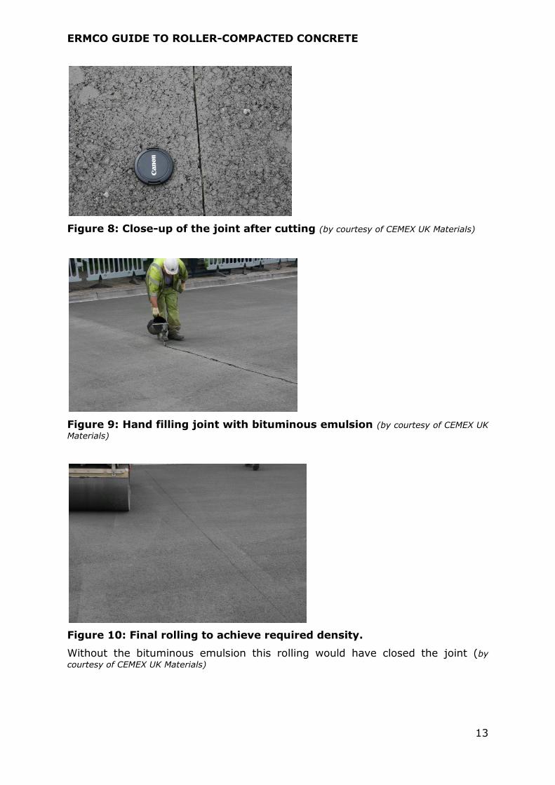
(Figure 6) and used to guide the operative who immediately uses a dry hand-held saw to cut a groove to about one third of the RCC depth, (Figure 7 and
Figure 8). The groove is then filled by hand with a C40B4 bituminous emulsion conforming to EN 13304, Figure 9 - this quality of bituminous emulsion is used because it is of a suitable viscosity for hand pouring. This is followed by the final
rolling to the required density, Figure 10. This final rolling tends to reduce the joint width and without the bituminous emulsion to act as a de-bonding agent,
the joint would have completely closed.
There is patented equipment to undertake a similar process automatically.
Figure 6: Rope being rolled into the position where a contraction joint is to be formed. (by courtesy of CEMEX UK Materials)
Figure 7: Hand cutting the contraction joint (by courtesy of CEMEX UK Materials)
ERMCO GUIDE TO ROLLER-COMPACTED CONCRETE
13
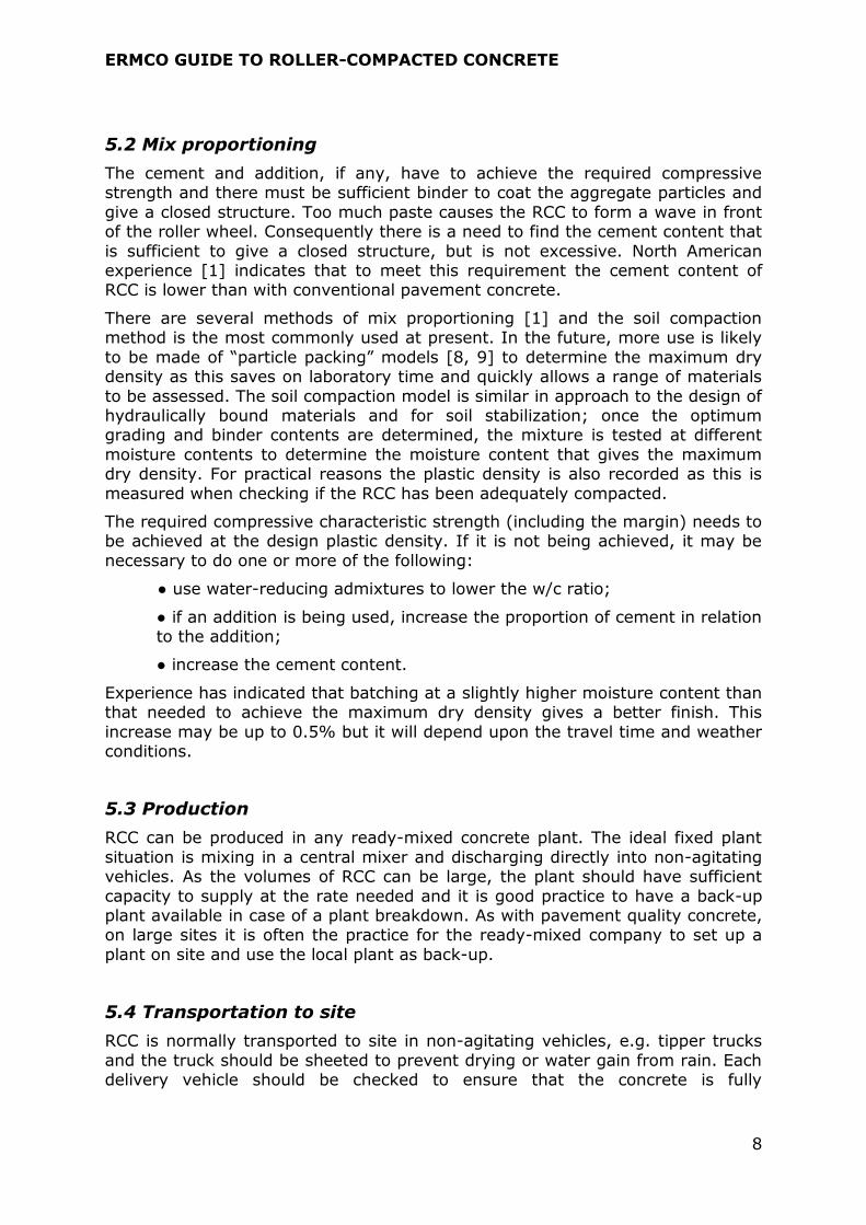
Figure 8: Close-up of the joint after cutting (by courtesy of CEMEX UK Materials)
Figure 9: Hand filling joint with bituminous emulsion (by courtesy of CEMEX UK
Materials)
Figure 10: Final rolling to achieve required density.
Without the bituminous emulsion this rolling would have closed the joint (by
courtesy of CEMEX UK Materials)

ERMCO GUIDE TO ROLLER-COMPACTED CONCRETE
14
It may also be necessary to provide isolation joints that accommodate differential settlement between an adjacent structure and the pavement and to
accommodate expansion of the pavement without harm to the structure or pavement. These are formed by tacking strips of fibreboard to the structure to
the full depth of the RCC. The RCC is then placed and rolled as with a normal restrained edge.
6.4 Curing
RCC has a low water content and consequently does not bleed but it is prone to
drying if not properly cured. Premature drying effectively stops hydration and reduces the strength and durability of the surface layer. The model specification
requires the use of a sprayed curing compound. In theory water-sprays and plastic sheeting for 7 days are also effective, but in practice the water spraying is often intermittent allowing drying between sprays, and plastic sheets are
difficult to keep in place when it is windy.
Curing is essential. If the contractor provides a practical alternative to sprayed
curing compounds in a proposed method statement, it should be accepted if it will achieve the prime objective of continuous curing of the surface layer. When
the air temperature is predicted to fall below 0C, water curing should not be
used as it increases the risk of freeze-thaw damage.
Depending on the degree of open surface texture and due to the absorptiveness
of the surface, the amount of curing compound may be as much as 1.5 to 2 times the application rate for conventional concrete [1].
6.5 Early opening strength
A major advantage of RCC over pavement quality concrete is the ability to open
it to traffic at a relatively early age. A “rule of thumb” used in the USA [1] is to open it to traffic when the compressive in-situ strength reaches about 20 N/mm2
cylinder strength. The rate of gain of strength is highly dependent upon a number of factors including cement type, RCC strength and the ambient conditions, all of which are site specific. In practice the requirement of 20
N/mm2 is achieved in about 2 days in warm weather and about 4 days in cooler weather. The model specification has the more onerous requirement of 7 days
after construction before trafficking. In most cases, a shorter period is not needed, but where it is an issue, the achievement of an in-situ strength of 20 N/mm2 is the fundamental criterion. These requirements relate to trafficking by
the public and not to trafficking by the contractor. The RCC will have been compacted by heavy machinery and therefore occasional site traffic is unlikely to
harm the RCC.
6.6 Trial area
If the concrete producer and placing contractor have not worked together using the same materials, the construction of a trial area is strongly advised as this
will demonstrate the suitability of the mix, method of placing, compaction and surface finish. The trial area should be at least two paver widths wide as this will
test the procedure for forming fresh joints in the longitudinal direction, see

ERMCO GUIDE TO ROLLER-COMPACTED CONCRETE
15
A.4.5.1. Where practical, the RCC should be placed over a base and sub-base that is similar to that intended for the main works and this will be a better
reflection of the placing conditions.
The trial area should be carefully planned with pre-determined acceptance
criteria. It should establish at least the following:
— the RCC can be delivered at an adequate rate;
— the RCC is uniformly mixed and has a moisture content at placing that can
be compacted to the required plastic density;
— the paver can place the RCC;
— the pattern of compaction and the number of passes achieves the required in-situ plastic density;
— the process can be completed at the limit of the time window;
— the surface tolerances are achieved;
— the surface finish is acceptable;
— the method for forming contraction joints works in practice;
— the method of forming longitudinal joints works in practice;
— the procedure for curing the surface works in practice.
Any issues or shortcomings identified during this trial should be discussed between the parties and solutions agreed before commencing the work.
The RCC trial area may be cored after placing to check the depth of construction, uniformity of compaction, bonding between layers and in-situ strength. However
any such requirements should be clearly identified in the project specification.
While providing a trial section may be expensive, the many benefits outweigh its cost and it has been often proven to be very cost effective in that problems are
identified and resolved before the main operations.
7. Assessment of conformity of RCC by the concrete producer
Conformity of the supplied RCC is usually based on conformity to the specified compressive strength class rather than on flexural strength.
The flexural tensile strength of concrete is dependent upon the test method.
Three and four-point tests on beams give different values with the four-point test on average giving lower values and the three-point test giving more
variability.
NOTE: These characteristics can be explained by the weakest-link theory. Once the weakest-link is broken, the crack spreads rapidly leading to complete failure. The larger the area under maximum stress, the more likely it will be that it contains a weaker-link. With the four-point test the surface opposite the two central loading points will have the maximum stress but in the three-point test
the maximum strength is just opposite the central loading point.
Compared with the compressive strength test, the flexural tensile tests have poor precision. Consequently it is almost universal practice to convert the design
flexural tensile strength into an equivalent compressive strength and use the

ERMCO GUIDE TO ROLLER-COMPACTED CONCRETE
16
compressive strength test to determine conformity. The relationship between compressive and flexural tensile strength given in EN1992-1-1 may be used for
this conversion or a specific relationship should be established by initial testing of the proposed mix.
When preparing compressive strength test specimens, the compaction method is not that used for normal concrete, but that used for hydraulically-bound materials, e.g. compaction with a vibrating hammer in accordance with
EN 13286-51. There is also a standard for testing the compressive strength of hydraulically-bound materials (EN 13286-41) but the model specification
requires the use of EN 12390-2 for curing and EN 12390-3 for testing as RCC has the strength of normal concretes.
As a minimum, the producer should show conformity to the compressive
strength at the sampling rate required by EN206.
8. In-situ testing of RCC
As the level of compaction on site is critical to achieving the required in-situ strength, routine measurements of plastic density according to BS 1924-2 or
equivalent are undertaken during construction using a nuclear density gauge. If the required plastic density is not achieved, further rolling is applied until it is achieved.
In a road the ideal place to take plastic density readings is in the wheel tracks. These can be taken as being approximately at one quarter and three quarters of
the lane width. The exact location is not critical and these positions can be assessed by eye. To keep things simple, this regime of testing is applied to all
pavement placing operations even when the concept of wheel tracks is not applicable, e.g. in parking areas.
The recommendations for the tolerances for industrial pavements are taken from
the Concrete Society Technical Report 66 [2].
9. References 9.1 Standards
EN 197-1 Cement — Part 1: Composition, specifications and conformity criteria
for common cements
EN 206 Concrete — Specification, performance, production and conformity
EN 1992-1-1 Eurocode 2. Design of concrete structures. General rules and rules for
buildings
EN 12390-2 Testing hardened concrete — Part 2: making and curing specimens for
strength tests
EN 12390-3 Testing hardened concrete — Part 3: Compressive strength of test
specimens
EN 13286-41 Unbound and hydraulically bound mixtures — Part 41: Test method for
the determination of the compressive strength of hydraulically bound
mixtures
EN 13286-51 Unbound and hydraulically bound mixtures — Part 51: Method for the
manufacture of test specimens of hydraulically bound materials by

ERMCO GUIDE TO ROLLER-COMPACTED CONCRETE
17
vibrating hammer compaction
EN 14227-1
Hydraulically bound mixtures – Specifications Part 1: Cement bound
granular mixtures
BS 1924-2 Stabilized materials for civil engineering purposes. Methods of test for
cement-stabilized and lime-stabilized materials (Obsolescent)
9.2 Other references
[1] NATIONAL CONCRETE PAVING TECHNOLOGY CENTER, Guide for roller-compacted
concrete pavements, August 2010.
[2] THE CONCRETE SOCIETY, External in-situ concrete paving, Technical report 66,
August 2007. ISBN 1-904482-37-6.
[3] URS Greiner Woodward Clyde, Roller-compacted concrete quality control manual,
Portland cement association, 2003.
[4] PITTMAN, D W and ANDERTON, G L, The use of roller-compacted concrete in the
United States, Sixth Int. Conf. on maintenance and rehabilitation of pavements and
technological control, Torino, Italy, 2009. http://www.mairepav6.it.uk/
[5] FEBELCEM, Les foundations routières liées au ciment, Febelcem Bulletin 33, Mai
2004.
[6] COMITÉ TECHNIQUE AIPCR DES ROUTES EN BÉTON EMPLOI DU BÉTON COMPACTÉ
DANS LES CHAUSSÉES (The use of roller compacted concrete for roads), 1993. (In
French and English).
[7] ADASKA, W, Mix design and construction of RCC, Portland Cement Association
(available on the Internet)
[5] DEWAR J D, Computer modelling of concrete mixtures, E & FN Spon, 1999. ISBN 0-
419-23020-3.
[6] DE LARRARD, Concrete mixture proportioning: a scientific approach, E & FN Spon,
1999.

ERMCO GUIDE TO ROLLER-COMPACTED CONCRETE
18
Annex A: Model specification for an RCC pavement
This model specification is intended to serve as a guide to the format and content for RCC pavement construction. There will always be some project
specific requirements, e.g. the compressive strength class of the RCC, and the following clauses should be checked for completeness and the project specific requirements added prior to adoption.
A.1 General requirements
Prior to manufacturing and placing roller-compacted concrete (RCC), a method statement shall be prepared and approved by the clients or their representative.
Where a trial placement is required by the project specification, a preliminary method statement shall be prepared and, after the trial placement, accepted or
modified and then approved by the clients or their representative.
The method statement shall include procedures to be followed if there is critical plant breakdown or sudden adverse weather conditions, e.g. a thunderstorm
with torrential rain.
The equipment and human resources listed in the method statement shall be
available on site during the placing, compaction and finishing of RCC.
The RCC shall conform to the quality, lines, levels and thickness given in the project specification.
A.2 Normative references
EN 206 Concrete — Specification, performance, production and conformity
EN 933-3 Tests for geometrical properties of aggregates — Part 3:
determination of particle shape — Flakiness index
EN 934-2 Admixtures for concrete, mortar and grout — Part 2: Concrete
admixtures — Definitions, requirements, conformity, marking and
labelling
EN 12620 Aggregates for concrete
EN 12390-2 Testing hardened concrete — Part 2: making and curing specimens
for strength tests
EN 12390-3 Testing hardened concrete — Part 3: Compressive strength of test
specimens
EN 12390-5 Testing hardened concrete — Part 5: Flexural strength of test
specimens
EN 12390-6 Testing hardened concrete — Part 6: Tensile splitting strength of test
specimens
EN 13286-51 Unbound and hydraulically bound mixtures — Part 51: Method for the
manufacture of test specimens of hydraulically bound materials by
vibrating hammer compaction
EN 13304 Bitumen and bituminous binders. Framework for specification of
oxidised bitumen
BS 1924-2 Stabilized materials for civil engineering purposes. Methods of test for
cement-stabilized and lime-stabilized materials (Obsolescent)

ERMCO GUIDE TO ROLLER-COMPACTED CONCRETE
19
A.3 Roller-compacted concrete
The constituents and production of concrete including batching tolerances shall conform to EN206 plus the requirements given in this specification.
Specimens of RCC shall be compacted in accordance with EN 13286-51 and cured in accordance with EN 12390-2. The EN 12390-3 procedure shall be used when determining the compressive strength of RCC specimens.
A.3.1 Additional requirements for constituents
The maximum aggregate size shall be not greater than 20mm.
All coarse aggregates when tested separately shall have an EN 12620, Los
Angeles category not greater than LA40.
All coarse aggregates when tested in accordance with EN 933-3 shall have an EN 12620 flakiness index category not greater than FI20.
Aggregates shall conform to the provisions valid in the place of use for the given exposure class, e.g. XF4.
Fine aggregate particles shall comprise hard durable materials such as siliceous sand.
A.3.2 Initial testing of RCC
The initial testing of RCC shall determine the relationships between moisture
content, dry density and plastic density. The moisture content to achieve the maximum dry density shall be determined. The initial testing shall prove that the
compressive strength at the maximum dry density or the intended density of
supply is 2σ above the specified compressive strength where σ is the estimated population standard deviation.
The initial testing shall also determine the plastic density at the maximum dry density or the intended plastic density of supply and this value shall be used for the 100% in-situ plastic density value.
Where the project specification requires the relationship between flexural strength and compressive strength to be established, the flexural strength shall
be measured in accordance with EN 12390-5. Testing shall be over the range used to determine the relationship between moisture content and dry density.
A.3.3 Conformity of compressive strength
The conformity of RCC to the specified compressive strength class shall be
undertaken in accordance with EN206 at the same minimum sampling rate as for the compressive strength of normal concretes. RCC shall be assessed as an
individual concrete or as part of a concrete family limited to RCC.
NOTE: Checking density prior to testing compressive strength is recommended.

ERMCO GUIDE TO ROLLER-COMPACTED CONCRETE
20
A.4 Construction requirements
A.4.1 Preparation of the sub-grade/sub-base
The sub-grade/sub-base shall be prepared to line and level as required by the
project drawings. The sub-grade shall be uniformly compacted to 95% of its maximum dry density. During this preparation of the sub-grade, any soft or
yielding material shall be removed and replaced with acceptable material or corrected, e.g. by soil stabilization. Where required by the project specification, the sub-base shall be uniformly compacted to 95% of its maximum dry density.
A.4.2 Trial section (where specified in the project specification)
At least 30 days prior to the paving operation, a trial section shall be constructed using the proposed mix. The location of the trial section shall be shown on the
project drawings or located by agreement. The trial section shall be at least 15 metres long and comprise at least two lane widths. The equipment, placing, compaction procedures and joint forming methods shall initially conform to the
preliminary method statement, but during the trial these may be varied if they do not achieve the specified requirements, e.g. the in-situ plastic density;
surface finish. Any variations of method shall be recorded and the preliminary method statement modified to reflect this experience. The trial shall include the formation of a longitudinal joint and if used, a contraction joint. This trial section
shall be constructed over an extended time period to demonstrate the constructability at the specified or agreed time limits for joint/second layer
construction.
On both diagonals of the trial area a series of nuclear density measurements shall be taken starting at 300mm from each corner to assess the uniformity of
compaction and the achievement of 98% of the plastic density at the maximum dry density or of the intended plastic density of supply.
The project specification may include a series of tests to be undertaken on this trial section. The type of test, number of tests and locations of the test samples shall be detailed in the project specification.
A.4.3 Transport to site
RCC may be transported to site in non-agitating vehicles fitted with sheeting to prevent premature drying of the RCC or water gain from rain or other sources.
Each delivery shall be fully discharged. The maximum time between batching and delivery shall not exceed 60 minutes except where another time has been agreed as being technically appropriate, e.g. when the RCC contains a retarder.
A.4.4 Placing, compaction and conformity of in-situ plastic density
RCC shall not be placed on standing water, snow or ice nor placed in heavy
rainfall. RCC shall not be placed when the ambient temperature is less than 5C.
If the air temperature is predicted to fall below 0C in the 24 hours after placing,
the RCC shall be protected from damage resulting from freezing.
Except where it is not practical, RCC shall be placed with an asphalt-type paving
machine followed by rolling to achieve on average 98% of the plastic density

ERMCO GUIDE TO ROLLER-COMPACTED CONCRETE
21
(see A.3.2). Small areas and RCC around obstructions may be placed by hand and rolled by machine. Walk-behind vibratory rollers or plate-vibrators shall be
used to compact areas inaccessible to larger rollers.
Conformity to the required in-situ density shall be measured every 20 lane
metres alternatively at one quarter and three quarters of the lane width.
NOTE: The width positions may be judged by eye.
The in-situ plastic density shall be measured with a calibrated nuclear density
gauge conforming to BS 1924-2 or equivalent. Each test shall comprise three readings taken at 120 degrees to each other using the same source rod hole and the density shall be taken as the average of the higher two readings. The
operation of the gauge shall be in accordance with the manufacturer’s instruction and the gauge shall be calibrated prior to use and at least at 28 day intervals
thereafter. The gauge shall be used in the direct transmission mode and lowered to within 25mm of the bottom surface of the layer. The plastic density shall be measured within two hours of compaction.
The average of 10 consecutive determinations of plastic density shall be 98% of the plastic density determined in the initial testing, in accordance with A.3.2
and no individual determination shall be less than 95% of the plastic density.
A.4.5 Joints
A.4.5.1 Fresh joints
Fresh joints shall be constructed within 60 minutes from placing the first surface.
The procedure for forming fresh joints shall be included in the method statement and applied.
A.4.5.2 Cold joints (construction joints)
When the ambient temperature is 5C to 25C and there is more than a 60 minute time difference (or some other agreed time) between placing a vertical surface and placing the adjacent RCC, the joint shall be treated as a cold joint.
The face of the pavement shall be cut so that it is vertical and the material outside of this cut surface and loose material removed. The cut back shall remove RCC that has not been fully compacted. Immediately prior to placing
fresh RCC against a vertical cold joint, the existing joint surface is wetted to make the surface moist.
Horizontal cold joints, i.e. between layers, shall be free of loose material and in a moist state immediately prior to placement of the next layer of RCC.
A.4.5.3 Contraction joints
Contraction joints shall be formed where shown on the project drawings.
Contraction joints shall be either formed or sawn. When sawn, the depth of sawing shall be at least 30% of the pavement thickness. Sawn contraction joints
shall be sealed with a suitable material.
The procedure and timing for forming contraction joints shall be included in the method statement and applied.

ERMCO GUIDE TO ROLLER-COMPACTED CONCRETE
22
A.4.5.4 Isolation joints
Isolation joints shall be formed by tacking 12mm fibreboard against the structure and then placing the RCC up to the fibreboard and compacting.
A.4.5.5 Expansion joints
If required on the project drawings, expansion joints shall be constructed as detailed in the project specification.
A.4.6 Curing and protection from early trafficking
Immediately after final rolling, the RCC pavement shall be protected from drying
by the application of a sprayed wax-based curing compound. Two coats shall be applied at right angles to each other with the first coat becoming tacky before
the second coat is applied. The whole surface shall be uniformly coated with curing compound.
Completed sections of RCC pavement may be opened to public traffic seven days
after construction.
NOTE: See guidance in 6.5.
A.4.7 Tolerances for industrial pavements
The thickness of the RCC shall be not more than 15mm less than the design
thickness.
The top surface of the RCC shall be within ± 15mm of the design level and in addition there shall be no ponding of water.
The surface regularity shall be as required by the contract documents This requirement does not apply when there is a change in gradient.
NOTE: These tolerances may not be applicable to RCC roads.