Embed Size (px)
Citation preview

http://www.iaeme.com/IJCIET/index.
International Journal of Civil Engineering and Technology (IJCIET)Volume 8, Issue 4, April 2017, pp.
Available online at http://www.iaeme.com/IJCIET/issues.
ISSN Print: 0976-6308 and ISSN Online: 0976
© IAEME Publication
ERECTION STAGE DYNAM
CABLE STAYED BRIDGE
CONSTRUCTION STAGE A
M. Tech. Structural Engg, SCALE,
VIT University,Vellore,Tamil Nadu, India
Professor, Department of Civil and Structural Engg, SCALE,
VIT University, Vellore, Tamil Nadu, India
Senior Technical Manager, Mida
ABSTRACT
There are various means and methods available in the construction industry for
the erection of bridges. The Cantilever Method is the most widely used erection
method for the construction of the cable stayed brid
analysis, the geometrical and boundary changes as well as the material properties
changes must be considered. However, considerable stresses are produced due to the
construction loads in the continuous structure. To determi
forces, the initial equilibrium state for dead load at the final stage must be determined
first. However, in order to obtain the desired cable force which satisfies the suitable
range of displacement and member forces, the enginee
numerous trial & error procedures. To find the cable pretension loads, the unit load
method is used in this study. For verification, the Finite Element software (Midas
Civil) is used to determine the cable forces using the functio
Also the construction stage analysis for the cable stayed bridge is explained using
software. Various parameters are influenced on the cable forces as well as pylon
forces. These are back span to main span ratio
Geometry, Cable system arrangements are varied, results are validated and all the
details are given in this paper.
Key words: Cable forces, Unknown Load Factor,
IJCIET/index.asp 252 [email protected]
International Journal of Civil Engineering and Technology (IJCIET) 2017, pp. 252–264 Article ID: IJCIET_08_04_032
http://www.iaeme.com/IJCIET/issues.asp?JType=IJCIET&VType=8&IType=3
6308 and ISSN Online: 0976-6316
Scopus Indexed
ERECTION STAGE DYNAMIC BEHAVIOR
CABLE STAYED BRIDGE USING
CONSTRUCTION STAGE ANALYSIS
Prataprao Jadhav
M. Tech. Structural Engg, SCALE,
VIT University,Vellore,Tamil Nadu, India.
Dr. G. Mohan Ganesh
Professor, Department of Civil and Structural Engg, SCALE,
VIT University, Vellore, Tamil Nadu, India.
Vinayagamoorthy M.
Senior Technical Manager, Midas IT, Mumbai, Maharashtra, India,
There are various means and methods available in the construction industry for
the erection of bridges. The Cantilever Method is the most widely used erection
method for the construction of the cable stayed bridges. For this type of structural
analysis, the geometrical and boundary changes as well as the material properties
changes must be considered. However, considerable stresses are produced due to the
construction loads in the continuous structure. To determine the cable installation
forces, the initial equilibrium state for dead load at the final stage must be determined
first. However, in order to obtain the desired cable force which satisfies the suitable
range of displacement and member forces, the engineers need to go through the
numerous trial & error procedures. To find the cable pretension loads, the unit load
method is used in this study. For verification, the Finite Element software (Midas
Civil) is used to determine the cable forces using the function Unknown Load Factor.
Also the construction stage analysis for the cable stayed bridge is explained using
software. Various parameters are influenced on the cable forces as well as pylon
back span to main span ratio, pylon height to deck span ratio,
Geometry, Cable system arrangements are varied, results are validated and all the
details are given in this paper.
Cable forces, Unknown Load Factor, Construction stage Analysis
asp?JType=IJCIET&VType=8&IType=3
BEHAVIOR OF
USING
NALYSIS
Professor, Department of Civil and Structural Engg, SCALE,
s IT, Mumbai, Maharashtra, India,
There are various means and methods available in the construction industry for
the erection of bridges. The Cantilever Method is the most widely used erection
ges. For this type of structural
analysis, the geometrical and boundary changes as well as the material properties
changes must be considered. However, considerable stresses are produced due to the
ne the cable installation
forces, the initial equilibrium state for dead load at the final stage must be determined
first. However, in order to obtain the desired cable force which satisfies the suitable
rs need to go through the
numerous trial & error procedures. To find the cable pretension loads, the unit load
method is used in this study. For verification, the Finite Element software (Midas
n Unknown Load Factor.
Also the construction stage analysis for the cable stayed bridge is explained using
software. Various parameters are influenced on the cable forces as well as pylon
span ratio, Pylon
Geometry, Cable system arrangements are varied, results are validated and all the
Construction stage Analysis

Prataprao Jadha V., G. Mohan Ganesh and Vinayagamoorthy M,
http://www.iaeme.com/IJCIET/index.asp 253 [email protected]
Cite this Article: Prataprao Jadha V., G. Mohan Ganesh and Vinayagamoorthy M,
Erection Stage Dynamic Behavior of Cable Stayed Bridge Using Construction Stage
Analysis, International Journal of Civil Engineering and Technology, 8(4), 2017, pp.
252–264.
http://www.iaeme.com/IJCIET/issues.asp?JType=IJCIET&VType=8&IType=3
INTRODUCTION
A cable stayed bridge is a type of bridge whose deck superstructure is supported by multiple
cables that run down to the main girder from one or more towers. The cable stayed bridges
are specially suited in the span range of 100 to 1000 m and thus provides a transition between
the continuous box girder bridges and the stiffened suspension bridges. It was developed in
Germany in the post war years in an effort to save steel which was then in short supply. Since
then many cable stayed bridges have been built all over the world. The cable stayed bridges
are economical over a wide range of span lengths and they are aesthetically attractive. The
wide application of the cable stayed bridge has been greatly facilitated in recent years by the
availability of high strength steels, the adoption of orthotropic decks using advanced welding
techniques and the use of electronic computers in conjunction with rigorous structural
analysis of highly indeterminate structures. The beauty and visibility of a cable stayed bridges
are mainly constructed using steel for stay cables, deck and towers. In some of the recent
constructions, the deck and towers has been constructed in structural concrete or a
combination of steel and concrete.
The cables are prestressed by introducing additional tensile force in the cables in order to
improve the stress in the main girder and tower at the completion stage, to prevent the
lowering of rigidity due to sagging of cable, and to optimize the cable condition for the
erection. The magnitude of the prestress is determined by taking into consideration the factors
such as the horizontal components of each cable tension is balanced such that there is no in-
plane bending of the tower due to unbalanced horizontal force due to dead load at the
completion stage, and the net force on the main girder at the connection of the cable at the
completion stage be assumed to be in certain limit.
The major issue of the design and erection of the cable-stayed bridges are to determine
and achieve the initial equilibrium configuration at the completed state. The initial
equilibrium configuration in case of cable-stayed bridges is the equilibrium condition due to
combined effect of dead load and tension forces in the stay cables.
There are various methods to determine the cable forces; these are classified as below;
1. Traditional "Zero Displacement" method
2. Force Equilibrium method
3. Force method
4. Unit Load method
In “Traditional Zero Displacement Method”, it is assumed as roller support at the cable
anchorage location of deck without cable and determines cable forces referring to the reaction
which is vertical component of cable force. Major concept of design is reducing bending
moment in tower and girders due to dead load.
In “Force Equilibrium Method”, it is assumed that all the cable support and tower
connection as fixed supports. The target bending moment distribution is obtained. The
condition is arrived as there would be zero moment in the pylon. In this case, nonlinearity due
to cable sag effect is ignored and pretension of cable at each end is assumed to be identical.
Force Equilibrium method considers the effect of this horizontal force.
Erection Stage Dynamic Behaviour of Cable Stayed Bridge Using Construction Stage Analysis
http://www.iaeme.com/IJCIET/index.asp 254 [email protected]
In “force method”, we can assume the member force by converting the structure as
determinate structure. Using the member forces due to live loads, member forces due to dead
loads can be obtained.
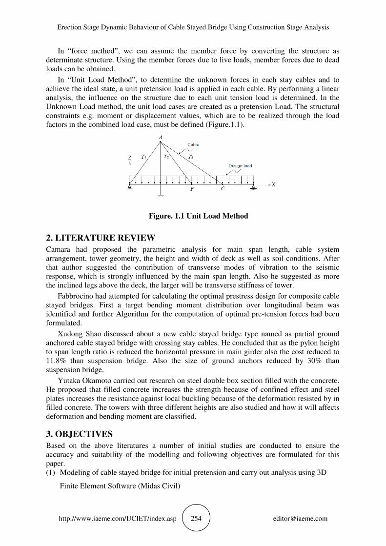
In “Unit Load Method”, to determine the unknown forces in each stay cables and to
achieve the ideal state, a unit pretension load is applied in each cable. By performing a linear
analysis, the influence on the structure due to each unit tension load is determined. In the
Unknown Load method, the unit load cases are created as a pretension Load. The structural
constraints e.g. moment or displacement values, which are to be realized through the load
factors in the combined load case, must be defined (Figure.1.1).
Figure. 1.1 Unit Load Method
2. LITERATURE REVIEW
Camara had proposed the parametric analysis for main span length, cable system
arrangement, tower geometry, the height and width of deck as well as soil conditions. After
that author suggested the contribution of transverse modes of vibration to the seismic
response, which is strongly influenced by the main span length. Also he suggested as more
the inclined legs above the deck, the larger will be transverse stiffness of tower.
Fabbrocino had attempted for calculating the optimal prestress design for composite cable
stayed bridges. First a target bending moment distribution over longitudinal beam was
identified and further Algorithm for the computation of optimal pre-tension forces had been
formulated.
Xudong Shao discussed about a new cable stayed bridge type named as partial ground
anchored cable stayed bridge with crossing stay cables. He concluded that as the pylon height
to span length ratio is reduced the horizontal pressure in main girder also the cost reduced to
11.8% than suspension bridge. Also the size of ground anchors reduced by 30% than
suspension bridge.
Yutaka Okamoto carried out research on steel double box section filled with the concrete.
He proposed that filled concrete increases the strength because of confined effect and steel
plates increases the resistance against local buckling because of the deformation resisted by in
filled concrete. The towers with three different heights are also studied and how it will affects
deformation and bending moment are classified.
3. OBJECTIVES
Based on the above literatures a number of initial studies are conducted to ensure the
accuracy and suitability of the modelling and following objectives are formulated for this
paper.
(1) Modeling of cable stayed bridge for initial pretension and carry out analysis using 3D
Finite Element Software (Midas Civil)

Prataprao Jadha V., G. Mohan Ganesh and Vinayagamoorthy M,
http://www.iaeme.com/IJCIET/index.asp 255 [email protected]
(2) Optimize the behavior of the cable stayed bridge under unit load method
(3) To arrive at maximum dynamic response of the bridge for the optimum pretension load
and determine cable forces
(4) Verification of results with analytical method.
(5) Carry out the construction stage analysis and determine the optimum cable forces in each
stage
4. WORK METHODOLOGY
To arrive the above objectives following stepwise methodology is adopted (Figure.4.1).
Figure. 4.1 Flow chart for work methodology
5. MODEL STUDY
The following modelling data is used for the calculations of example model. A simple 2D
Cable stayed model is chosen to clarify main considerations in modelling and to determine
the cable forces. Figure.5.1 shows a schematic representation of the cable stayed bridge. The
structure is modelled using the following data considerations (Refer Table 5.1 to Table5.3).
Table 5.1. Material data of the model
Classification Modulus of Elasticity (kN/m2) Poisson’s Ratio
Deck 2.7386e+007 0.2
Pylon 2.7386e+007 0.2
Cable 2.0500e+008 0.3
Defining Scope of work
Data consideration
Modelling using Midas Civil
Analysis
Numerical Analysis
Results & Discussion
Conclusion

Erection Stage Dynamic Behaviour of Cable Stayed Bridge Using Construction Stage Analysis
http://www.iaeme.com/IJCIET/index.
Classification Cross
Deck
Pylon Top
Pylon Bottom
Cable
Table 5.3
Classification
Dead load
Cable pretension 1
Cable pretension 2
Cable pretension 3
Cable pretension 4
A concrete deck having grade M40 consists of span of 10m is considered and is
with conventional beam element. A P
7.5m is also modelled as bea
modelling as they cannot take
(Figure.5.1).
Figure. 5.1 Example Bridg
The results shows that, the bending moment profile (
equilibrium condition, is unit pretension forces and the displacements are checked for
condition as shown in table 5.4.
The procedure adopted to get the final cable forces is formulated using Finite Element
software (Midas Civil). The steps required to get cable forces are explained using following
figures (Figure 5.3 to Figure 5.6)
5m
A B
Erection Stage Dynamic Behaviour of Cable Stayed Bridge Using Construction Stage Analysis
IJCIET/index.asp 256 [email protected]
Table 5.2. Section data of the model
Cross-section Area (m2) Moment of Inertia(m
0.0225 7.11 e-5
0.04 2.25 e-4
0.07 5.184 e-4
3.15 e-4
1.57 e-8
Table 5.3. Loading data of the model
Load Type Load
Self weight -1(Factor)
Cable pretension 1 Pretension Loads 1 kN
pretension 2 Pretension Loads 1 kN
Cable pretension 3 Pretension Loads 1 kN
Cable pretension 4 Pretension Loads 1 kN
A concrete deck having grade M40 consists of span of 10m is considered and is
ment. A Pylon having grade M40 consists of overall height of
am element. For cables, the truss type of element is used for
cannot take the effects such as sag effect and non linear effects
Example Bridge model Figure. 5.2 Bending moment envelope
, the bending moment profile (Figure. 5.2) will be arrived for i
unit pretension forces and the displacements are checked for
table 5.4.
The procedure adopted to get the final cable forces is formulated using Finite Element
software (Midas Civil). The steps required to get cable forces are explained using following
figures (Figure 5.3 to Figure 5.6)
4.5m
3m5m
C D
Erection Stage Dynamic Behaviour of Cable Stayed Bridge Using Construction Stage Analysis
Moment of Inertia(m4)
4
1(Factor)
A concrete deck having grade M40 consists of span of 10m is considered and is modelled
grade M40 consists of overall height of
the truss type of element is used for
the effects such as sag effect and non linear effects
Bending moment envelope
5.2) will be arrived for initial
unit pretension forces and the displacements are checked for these
The procedure adopted to get the final cable forces is formulated using Finite Element
software (Midas Civil). The steps required to get cable forces are explained using following

Prataprao Jadha V., G. Mohan Ganesh and Vinayagamoorthy M,
http://www.iaeme.com/IJCIET/index.
Table 5.4 Displacement resul
Node No Self
Dx
17 0.025
19 -0.001
22 0.001
2 -0.025
Node No Pretension 3
Dx
17 0.006
19 0.002
22 0
2 0
Figure 5.3 Unknown Load Factor
Figure 5.6
Prataprao Jadha V., G. Mohan Ganesh and Vinayagamoorthy M,
IJCIET/index.asp 257 [email protected]
Table 5.4 Displacement results for bridge model (m)
Self-Weight Pretension 1 Pretension 2
DZ Dx Dz Dx
-0.214 -0.005 -0.06 0.001
0.001 -0.201 0 0.049 0.001
-0.201 -0.001 0.033 0
0.025 -0.214 -0.001 0.069 0.005
(Continue)
Pretension 3 Pretension 4 Pretension 5
DZ Dx Dz Dx
0.164 0 -0.017 0.027
0.012 0 -0.008 0.002
-0.008 -0.002 0.0112 -0.002
-0.017 -0.006 0.164 -0.027
oad Factor Figure 5.4 Constraints in terms of displacements (m)
Figure 5.5 Unknown Load values
Figure 5.6 Optimized cable pretension loads
Prataprao Jadha V., G. Mohan Ganesh and Vinayagamoorthy M,
ts for bridge model (m)
Pretension 2
Dz
0.069
0.033
0.049
-0.06
Pretension 5
Dz
-0.059
-0.115
-0.115
-0.059
Constraints in terms of displacements (m)

Erection Stage Dynamic Behaviour of Cable Stayed Bridge Using Construction Stage Analysis
http://www.iaeme.com/IJCIET/index.asp 258 [email protected]
6. ANALYTICAL METHOD (STIFFNESS MATRIX METHOD)
The method used for optimization of tensions of cables at the initial equilibrium position of a
cable structure is unit load method. The initial cable forces are calculated by considering the
constraints such as displacement, moment, etc. and satisfy the constraints. If we use the
unknown load factor of FEM software, we can minimize the trials to determine the optimized
pretension forces. In this function, by defining the constraint condition of
displacement/reaction/member force in a certain range, we can determine the unknown cable
pretension forces.
The following procedure explains the analysis for finding the jack-up loads at Points A, B
as shown in Figure 1.1
• Apply a pretension load in the direction of the unknown jack-up loads as shown in Figure
1.1, one at a time. The number of unit load conditions created should be equal to the
number of the unknown loads.
• Carry out a static analysis for the given loadings. Loading condition is self weight load in
this case.
• Formulate Equality conditions using the Constraints imposed.
Using linear algebraic equations, these equality conditions can be solved. If the numbers
of the unknown loads and equations are exactly equal, the solution can be readily obtained
from the matrix method or the linear algebra method also. ����� + ����� + ����� + ����� + �� = �� Eq. (1) ����� + ����� + ����� + ����� + �� = �� Eq. (2) ��� = displacement at point A due to the unit load applied at P1 direction ��� = displacement at point B due to the unit load applied at P2 direction �� = displacement at point A due to the design loading condition �� = displacement at point B due to the design loading condition �� = displacement at point A due to the design loading condition and unknown loads �� = displacement a point B due to the design loading condition and unknown loads
For the current model, to find the initial cable tension loads T1, T2, T3 & T4 that limits the
lateral at point A which is less than δA and vertical displacements a displacement points B, C
and D which are greater than zero for the given loading condition (Figure 5.1).
Using the constraints the equality conditions are formulated. T1, T2, T3 & T4 are Unknown
Load factors or Optimized Cable Forces. Following equations are used to form the influence
matrix. ����� + ����� + ����� + ����� + �� = �� Eq. (3) ����� + ����� + ����� + ����� + �� = �� Eq. (4) ����� + ����� + ����� + ����� + �� = �� Eq. (5) ���� + ���� + ���� + ���� + � = � Eq. (6)
If the numbers of the unknown loads and equations are exactly equal, the solution can be
obtained from simultaneous equation method or the matrix method also.

Prataprao Jadha V., G. Mohan Ganesh and Vinayagamoorthy M,
http://www.iaeme.com/IJCIET/index.
���������After putting all the values, we get following simultaneous equations.��0.06��� + �0.069��� + �0.164�0.049��� + �0.033��� + �0.012�0.033��� + �0.049��� + ��0.008�0.069��� + ��0.06��� + ��0.017Solving the equations (7) to (10)��= 0.991985, ��= 1.018489,
7. CONSTRUCTION STAGE ANALYSIS
To determine the cable forces that are introduced at cable installation
equilibrium condition for dead load at the final stage must be determined first. Then,
construction stage analysis according to the sequence
general, with forward construction stage analysis, we cannot obtain cable pretension loads for
each stage which satisfy the initial equilibrium at the final stage.
The Bhim Gowda Bridge
span Steel composite cable-sta
deck is of 13.6 m wide. It consists
beams at spacing of 3 m and a
stayed section is supported by
of configuration on each side
Each reinforced concrete pylon co
supporting the deck. Figure. 7.1 shows
view. A model of the completed
in Figure. 7.1 considering the geometrical and material
Figure. 7.1 Bhim Gowda cable
Prataprao Jadha V., G. Mohan Ganesh and Vinayagamoorthy M,
IJCIET/index.asp 259 [email protected]
� = ��� ��� ��� ������ ��� ��� ������ ��� ��� ����� �� �� ��� � �� ����� ����� ���� ���
putting all the values, we get following simultaneous equations. � 164��� + ��0.017��� + ��0.214� = ��0.059� � 012��� + ��0.008��� + ��0.201� = ��0.115� � 008��� + �0.0112��� + ��0.201� = ��0.115� � 017��� + �0.164��� + ��0.214� = ��0.059� (7) to (10), the unknown cable forces are calculated
= 1.018489, �"= 0.983432, �#= 1.002321
STAGE ANALYSIS
cable forces that are introduced at cable installation
for dead load at the final stage must be determined first. Then,
construction stage analysis according to the sequence of construction
with forward construction stage analysis, we cannot obtain cable pretension loads for
each stage which satisfy the initial equilibrium at the final stage.
at Haridwar is used for modelling in this paper
ayed bridge with overall length of 130m (65m
consists two longitudinal steel girders 2.5 m
a reinforced concrete slab of 250 mm deep.
supported by a total of 14 cables. The cables are arranged
side of the pylon, in two planes on either side of
lon comprises one tower and two cross bea
7.1 shows a schematic representation of the bridge
leted Bhim Gowda cable-stayed bridge in FEM software
geometrical and material properties.
Bhim Gowda cable-stayed bridge at completed stage
Prataprao Jadha V., G. Mohan Ganesh and Vinayagamoorthy M,
�
Eq. (7)
Eq. (8)
Eq. (9)
Eq. (10)
the unknown cable forces are calculated,
cable forces that are introduced at cable installation time, the initial
for dead load at the final stage must be determined first. Then,
of construction is performed. In
with forward construction stage analysis, we cannot obtain cable pretension loads for
is used for modelling in this paper consists of 2-
m+ 65m each). The
m deep, transverse
The deck of cable-
arranged in semi-fan type
side of the bridge deck.
ams, the lower one
e bridge with elevation
bridge in FEM software is shown
at completed stage
Erection Stage Dynamic Behaviour of Cable Stayed Bridge Using Construction Stage Analysis
http://www.iaeme.com/IJCIET/index.asp 260 [email protected]
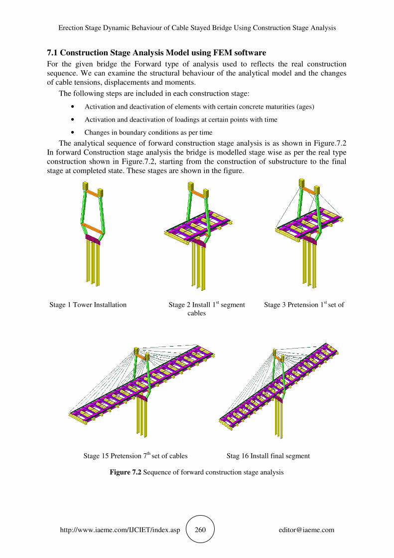
7.1 Construction Stage Analysis Model using FEM software
For the given bridge the Forward type of analysis used to reflects the real construction
sequence. We can examine the structural behaviour of the analytical model and the changes
of cable tensions, displacements and moments.
The following steps are included in each construction stage:
• Activation and deactivation of elements with certain concrete maturities (ages)
• Activation and deactivation of loadings at certain points with time
• Changes in boundary conditions as per time
The analytical sequence of forward construction stage analysis is as shown in Figure.7.2
In forward Construction stage analysis the bridge is modelled stage wise as per the real type
construction shown in Figure.7.2, starting from the construction of substructure to the final
stage at completed state. These stages are shown in the figure.
Stage 1 Tower Installation Stage 2 Install 1st segment Stage 3 Pretension 1
st set of
cables
Stage 15 Pretension 7th
set of cables Stag 16 Install final segment
Figure 7.2 Sequence of forward construction stage analysis

Prataprao Jadha V., G. Mohan Ganesh and Vinayagamoorthy M,
http://www.iaeme.com/IJCIET/index.asp 261 [email protected]
8. RESULTS INTERPRETATION
The parameters used for studying construction stage analysis are Displacement contour,
bending moment diagram, reactions at supports, unknown load factors.
8.1 Deformation Contour
Figure 7.3 Deformation at final construction stage
The maximum resultant displacement at deck portions are shown in the Figure. (7.3) which is
45.61 mm from legend.
8.2 Bending Moment Diagram
Figure. 7.4 Bending Moment Diagram final construction stage
The Bending moment diagram at completed stage (Figure.7.4) is same as the target
bending moment diagram which is assumed to be for initial conditions. The resultant bending
moment diagram is shown which are equally distributed and have permissible moments at
final stage.
8.3 Reaction Diagram
The reactions at all the supports are calculated as shown in Figure.7.5. The axial compression
resultant reactions are shown at pier bottom through pylon, as well as the outer reactions are
considered for design of abutments.

Erection Stage Dynamic Behaviour of Cable Stayed Bridge Using Construction Stage Analysis
http://www.iaeme.com/IJCIET/index.
Figure
8.4 Unknown Load Factors
Figure 7.6 Unknown Load Factors for final construction stage
The cable forces in terms of unknown load factors are found using the Finite Element
software (Midas Civil) for the initial pretension cable forces at
8.5. Parametric Analysis
Various parameters are influenced on the cable forces as well as pylon forces. These
parameters are back span to main span ratio
Geometry
Side span L
Main span L$%&'Ratio
Pylon Force (kN)
From Table 7.1 it is observed that
pylon compressive forces are increases considerably.
Table 7.2 shows that, for different types of tower geometry, the pylon axial compressive
forces are varying considerably.
properties the single pylon tower and two plane tower are effective in load transfer.
Erection Stage Dynamic Behaviour of Cable Stayed Bridge Using Construction Stage Analysis
IJCIET/index.asp 262 [email protected]
Figure. 7.5 Reactions at final construction stage
8.4 Unknown Load Factors
Unknown Load Factors for final construction stage
The cable forces in terms of unknown load factors are found using the Finite Element
software (Midas Civil) for the initial pretension cable forces at completed stage
Various parameters are influenced on the cable forces as well as pylon forces. These
span to main span ratio, pylon height to deck span ratio
Table 7.1 Result – Pylon Forces
Side span LS (m) 3.5 5 7.5
Main span LM (m) 15 15 15
0.25 0.33 0.5
Pylon Force (kN) 172.60 214.70 224.80
From Table 7.1 it is observed that, as the ratio of side span to main span increases, the
pylon compressive forces are increases considerably.
for different types of tower geometry, the pylon axial compressive
considerably. It is found that for the same geometrical and material
properties the single pylon tower and two plane tower are effective in load transfer.
Erection Stage Dynamic Behaviour of Cable Stayed Bridge Using Construction Stage Analysis
Unknown Load Factors for final construction stage
The cable forces in terms of unknown load factors are found using the Finite Element
completed stage (Figure.7.6).
Various parameters are influenced on the cable forces as well as pylon forces. These
ylon height to deck span ratio, tower / Pylon
as the ratio of side span to main span increases, the
for different types of tower geometry, the pylon axial compressive
It is found that for the same geometrical and material
properties the single pylon tower and two plane tower are effective in load transfer.

Prataprao Jadha V., G. Mohan Ganesh and Vinayagamoorthy M,
http://www.iaeme.com/IJCIET/index.asp 263 [email protected]
Table 7.2 Result – Pylon Forces
Geometry Type Pylon Forces (kN)
Single Plane Tower 382.5
Two Plane Tower 520.2
A-frame or inverted Y-shape 142.20
Diamond configuration 144.35
Table 7.3 Result – Cable Forces & Pylon Forces
Height of Pylon(m) 3 4 5 6 7 7.5
Main Span(m) 15 15 15 15 15 15
)*+,-./0123450-%65- Ratio 0.2 0.266 0.333 0.4 0.466 0.5
Cable Force (kN) 240.69 206.08 185.288 171.87 162.67 158.50
Pylon Force (kN) 216.87 215.93 214.98 214.01 213.29 206.66
From Table 7.3 it is observed that, as the ratio of height of pylon to main span increases,
the pylon compressive forces as well as cable forces are reduces apparently .But compared to
the pylon forces there is considerable decrease in cable forces for the same material and
geometrical properties.
8. CONCLUSION
After the examination of the construction stage analysis, the given model shows the
importance of the consideration of changing configuration at each stage. Here, the activation
to a deformed or undeformed deck and the cables will lead to a wrong estimation of cable
forces. The ideal cable forces are determined to achieve an optimal structural performance
due to its permanent loads. For the construction stage analysis, 17 various stages are modelled
using Finite Element Software so that they allow to include each erection stage.
Most of the calculated cable forces are equal to the final forces of the compared data with
the software. In the performed analysis, the initial stressing of the cables is applied in terms of
pretension load which is not a basic parameter. Therefore, the construction loads must be
accurately define to obtain the initial cable forces. The model does not include any geometric
as well as material non-linearity in the analysis of construction stage. A final calculation
should be done to consider these effects into account as they may optimize the cable forces.
Complete understanding of a structure is necessary to use the above optimization
techniques for finding design variables. The parameters like back span to main span ratio,
pylon height to deck span ratio, pylon geometry, cable system arrangements are compared
and results are drawn as bridge with back span to main span ratio lies between 0.25 and 0.5,
the height of pylon lies between L/8 to L/15, the inverted ‘Y’-shaped towers and diamond
configuration are less effective in load transfer than two plane tower.
Erection Stage Dynamic Behaviour of Cable Stayed Bridge Using Construction Stage Analysis
http://www.iaeme.com/IJCIET/index.asp 264 [email protected]
ACKNOWLEDGEMENT
The authors wish to thank the supports provided by the VIT University Vellore. Also they
would like to special thank to the entire team from Midas IT, R&D, Mumbai, Maharashtra for
their valuable support.
REFERENCES
[1] A.Camara, E. Efthymiou,Deck–tower interaction in the transverse seismic response of
cable-stayed bridges and optimum configurations, Engineering Structures, 124, (2016)
494–506
[2] F. Fabbrocino, M. Modano, I. Farina, G. Carpentieri, F. Fraternali, Optimal prestress
design of composite cable-stayed bridges, Journal of Composite Structures, (2016),1-6
[3] Xudong Shao,Jia Hu, Lu Deng,and Junhui, Conceptual Design of Superspan Partial
Ground-Anchored Cable-Stayed Bridge with Crossing Stay Cables, Journal of Bridge
Engineering, 1, (2014),11-15
[4] Yutaka Okamoto,Shunichi Nakamura, Static and seismic studies on steel/concrete hybrid
towers for multi-span cable-stayed bridges, Journal of Constructional Steel Research,67,
(2011), 203–210
[5] M.Vinayagamoorthy, Dr. G. Mohan Ganesh, Dr. A.S. Santhi, Secondary analysis for Pile
foundation by P-∆ Method, International Journal of Applied Engineering Research,11,
(2016),1579-1582
[6] D.Johnson Victor, Essentials of Bridge Engineering, Oxford and IBH Publications, Sixth
Edition, (2007)
[7] N. Krishna Raju, Design of Bridges, Third Edition, (2007)
[8] IRC: 6-2014, Code of Practice for Concrete Road Bridges, (2011)
[9] Midas Civil Help and Analysis Manual
[10] Suhas S Vokunnaya, Ravindranatha and Tanaji.Thite, Construction Stage Analysis of
Segmental Cantilever Bridge. International Journal of Civil Engineering and Technology,
8(2), 2017, pp. 373–382.
[11] G. M. Savaliya, Prof. (Dr.) A. K. Desai and Prof.(Dr.) S. A. Vasanwala. The Effect of
Lateral Configuration on Static and Dynamic Behaviour of Long Span Cable Supported
Bridges, International Journal of Civil Engineering and Technology, 6(11), 2015, pp. 156-
163. G. M. Savaliya, Prof. (Dr.) A. K. Desai and Prof.(Dr.) S. A. Vasanwala. The Effect
of Lateral Configuration on Static and Dynamic Behaviour of Long Span Cable
Supported Bridges, International Journal of Civil Engineering and Technology, 6(11),
2015, pp. 156-163.
[12] K.V. Ramana Reddy,(2014), Aerodynamic Stability of A Cable Stayed Bridge,
International Journal of Civil Engineering and Technology, 5(5), pp. 88-96.