Embed Size (px)
DESCRIPTION
Erection Procedure SCR
Citation preview
Page 1 of 23
ERECTION PROCEDURE/SEQUENCE
&
CRITICAL CHECKS
DURING
ERECTION AND PRE-COMMISSIONING
FOR
REV. STACKER/RECLAIMER
FOR
KOTHAGUDEM TPP, APGENCO
(A/C BSBK)
OUR ORDER NO.: CO/2242
M/C. NO.: HM/554
Page 2 of 23
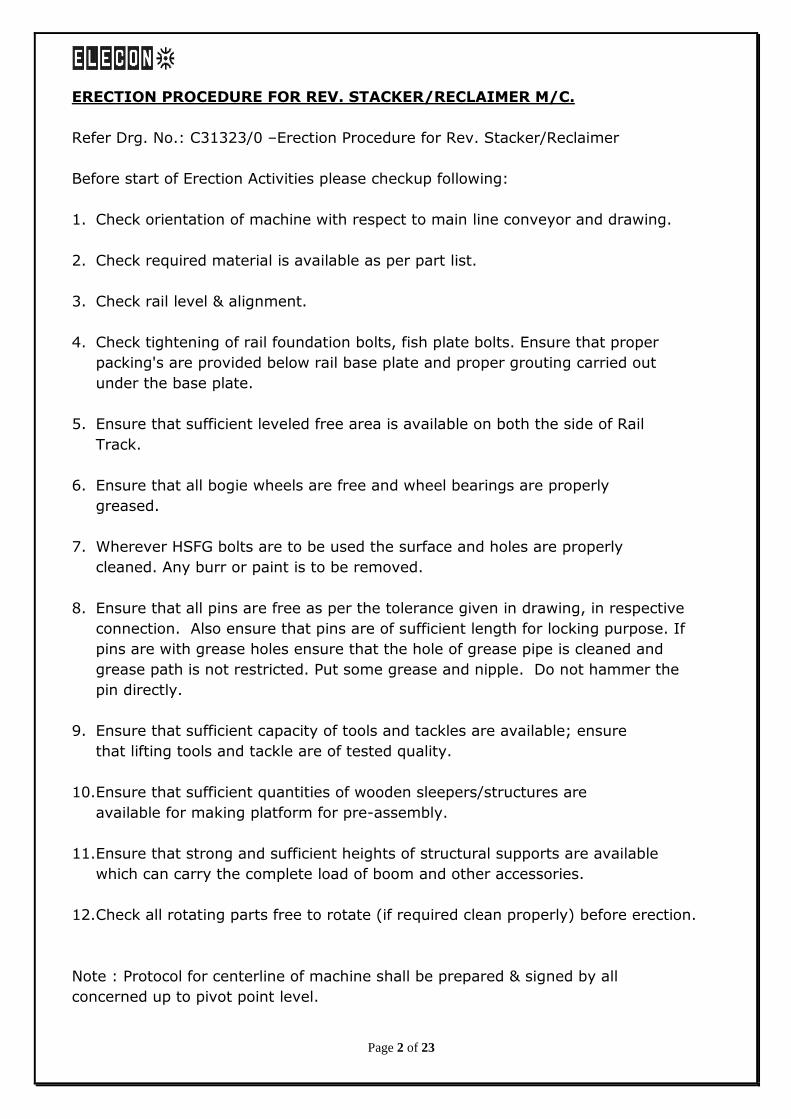
ERECTION PROCEDURE FOR REV. STACKER/RECLAIMER M/C.
Refer Drg. No.: C31323/0 –Erection Procedure for Rev. Stacker/Reclaimer
Before start of Erection Activities please checkup following:
1. Check orientation of machine with respect to main line conveyor and drawing.
2. Check required material is available as per part list.
3. Check rail level & alignment.
4. Check tightening of rail foundation bolts, fish plate bolts. Ensure that proper
packing's are provided below rail base plate and proper grouting carried out
under the base plate.
5. Ensure that sufficient leveled free area is available on both the side of Rail
Track.
6. Ensure that all bogie wheels are free and wheel bearings are properly
greased.
7. Wherever HSFG bolts are to be used the surface and holes are properly
cleaned. Any burr or paint is to be removed.
8. Ensure that all pins are free as per the tolerance given in drawing, in respective
connection. Also ensure that pins are of sufficient length for locking purpose. If
pins are with grease holes ensure that the hole of grease pipe is cleaned and
grease path is not restricted. Put some grease and nipple. Do not hammer the
pin directly.
9. Ensure that sufficient capacity of tools and tackles are available; ensure
that lifting tools and tackle are of tested quality.
10.Ensure that sufficient quantities of wooden sleepers/structures are
available for making platform for pre-assembly.
11.Ensure that strong and sufficient heights of structural supports are available
which can carry the complete load of boom and other accessories.
12.Check all rotating parts free to rotate (if required clean properly) before erection.
Note : Protocol for centerline of machine shall be prepared & signed by all
concerned up to pivot point level.
Page 3 of 23
STARTING OF ERECTION
(A) ERECTION OF WHEEL BOGIES :
1. Check centerline of machine and levels of rail track. It should be within the rail
laying tolerances (Refer drg. no.: C30815/4)
2. Mark wheel centers on the rail and mark parallel line at a distance of wheel center
on opposite side of rail. Measure diagonal dimensions and ensure that
corresponding diagonal dimensions are equal.
3. Place all 2 wheel drive/Non drive bogies, supporting arm 4 wheel bogies and
supporting arm 8 wheel bogies in position with reference to lines as mentioned in
above point no. 2 and lock the bogie wheels in position. While placing the bogies
on each other
4. Check alignment of bogies.
5. Now erect the compensating beam on 4 wheel bogies and check the dimensions
horizontally and vertically
6. Erect the rail clamps & storm clamps as per the orientation shown in drawing,.
7. Erect the rail scrapers with bogies as shown in the relevant drawing.
Now Check The Following Points:
a) Check level of platform and compensating beam.
b) Check centerline of compensating beam center holes and bogies..
c) Check verticality of compensating beam.
d) Check the torque of HSFG bolts as specified in drawing;
(B) ERECTION OF UNDER CARRIAGE:
1. Assemble the under carriage on leveled platform. Check the match marking. Lift
and place the under carriage. Complete the assembly of under carriage with
bogies and compensating beam.
2. Check the site weld joint (Ultrasonic welded joint) of under carriage.(protocol)
3. Check assembly of compensating beam pin and plain spherical bearing.
Page 4 of 23
4. Now move the complete assembly for about 3-4 meter in reverse and forward
direction. Before moving the assembly ensures that the lock provided for wheels
are removed.
(C) ERECTION OF SLEWING RING :
CAUTION: e.g. for burrs,solvent,radial impact, "S" mark etc.
1. Clean the surface of under carriage where slewing ring is to be fixed & ensure that
there is no welding beads, burrs, excessive paint residues and other irregularities
are observed.(Protocol)
2. Clean all holes and ensure that there should not be any burrs/ high spot.
3. A flat contact surface free from grease & oil is required for the slew bearing
installation.
4. The preservation has to be removed from the contact surfaces of the bearing.
Attention : Prevent any solvent from contacting the seals and from entering into
the raceways! Do not paint the seals!
5. Ensure that the support provided for lifting of slewing ring are proper.
6. Lift the slewing ring carefully in horizontal position with adequate lifting tools
and place it on under carriage. Radial impact must be absolutely avoided.
Check that bolt holes in the bearing line up with the holes in the under & upper
carriage. otherwise bearing may become distorted.
7. Ensure that the `S’ mark provided on the slewing ring is properly placed as per
Mark shown in the drawing. It should be always kept in minimum loading zone. If
the `S’ marks is not shown in drawing, please confirm the position of `S’ mark
with Design Deptt.
8. Insert all outer ring bearing fixing bolts of strength class 10.9 hand tight, turn the
non-bolted ring at least twice through 360 deg.
Pretension the bolts carefully crosswise with a suitable tool to the required
torque.(as per the torque value provided elsewhere)
9. Similarly, erect the toothed rim as per the marking on the under carriage and
align with bearing center.
10. After alignment of slew bearing and toothed rim please ensure locking with
providing lock plates as per drg.
Page 5 of 23
(D) ERECTION OF UPPER CARRIAGE:
CAUTION: "S" mark position, burrs, gap, free movement/jerk, backlash etc.
1. Assemble the Upper Carriage on leveled platform.
2. Check the level and site weld joint (Ultrasonic welded joint) of upper
carriage.(Protocol)
3. Clean the matching surface.
4. Clean the holes for slewing ring mounting and ensure that there should not be
any burrs/ high spot.
5. Any uneven surface should be matched properly.
6. If possible complete the lubrication system for slewing mechanism.
7. Lift the upper carriage and place carefully on the slewing ring.
8. Ensure that centre line of upper carriage and under carriage are matched without
disturbing the `S’ mark position.
9. Put connection bolt and tight the bolt in step and in sequence up to the specified
torque.
10. Ensure that there should not be any gap between upper carriage and slewing ring.
11. Slew the upper carriage manually in right and left direction and ensure free
movement. If any jerk or restriction observed rectify the same immediately and
check again the movement.
12. Now check the Pivot center distance. Ensure that there is sufficient clearance of
insertion of boom eye.
13. Check the assembly of Boom Pin with pivot and connecting part of boom.
14. Assemble both side slewing shaft and hydraulic drive and complete the alignment.
15. Check the backlash between pinion and toothed rim ring on three teeth. The
backlash to be readily adjusted to 0.03 to 0.04 x module. Ensure that the contact
surface between two teeth is minimum 75% to 80 %.
16. Erect the walkway, gratings & hand railings for the upper carriage.
Page 6 of 23
(E) ERECTION OF B.W. BOOM:
Before assembly of Boom Part ensure that sufficient capacity crane/tools are available to
lift the boom in one full length. While lifting the boom ensure that sling provided should
not damage the boom structure.
1. Assemble the boom on leveled platform.
2. Check the line and level of boom.(protocol)
3. Check centerline of conveyor.
4. Erect temporary supporting structure for boom in such a way that when boom is
placed on it, the boom should be in horizontal position.
5. Check the boom connection with pivot pins.
6. Ensure that ground is strong enough to take complete load of boom and other
accessories. If required provide guys to temporary structure.
7. If it is not possible to lift the boom in one piece, provide auxiliary supporting
structure near the joint on both ends.
8. Ensure that while joining two parts both sides should be kept in line and level.
(F) INSTALLATION OF HYDRAULIC CYLINDER:
CAUTION:-Cleaning, no emery paper, free movement etc.
Before erecting of hydraulic cylinders, please check the following:
1. Cleaning of cylinder, body and piston rod. Do not use emery paper/file for
cleaning of piston rod. Clean it with either pure petrol or paraffin.
2. If the cylinder is kept in storage for longer time (more than a year) remove oil
inside the cylinder by opening the drain plug and fill up new hydraulic oil.
3. Provide protective cover to cylinder valves.
4. Ensure that Pins for cylinder connection as per size & length is sufficient.
5. Check clearance between cylinder eye and connecting bracket.
While erecting of cylinders do not apply any excess pull or push force. For adjusting
cylinder position, loose vent screw so that cylinder can be moved freely. Cover the
exposed portion of piston rod with protective cover.
Page 7 of 23
(G) ERECTION OF MAST AND SUSPENSION:
1. Ensure that mast connection is having sufficient clearance with respective
connection part of boom.
2. Check the site weld joint (Ultrasonic welded joint) of mast.(Protocol)
3. Lift & put mast on bucket wheel boom & check level & verticality. Tie the mast
keeping it vertically with guys/ or any supports.. The guys should be provided in
such a way that it should not obstruct while erecting counter weight boom.
4. Ensure that all pins are of proper size & locked as per provision in the drg. (as per
the tolerance) in respective holes.
5. Ensure that all link plates are straight and length of link plates on either side
should be equal as per the drawing.
6. Connect the link plate with mast and tie the link plate with mast such that it
should not obstruct while doing erection.
7. Complete the erection of suspension with mast & B.W.Boom.
(H) ERECTION OF COUNTER WEIGHT BOOM :
1. Complete the counter weight boom assembly with the counter weight box on
ground.
2. Ensure that the pin connection is having sufficient clearance with respective
connection.
3. Erect the counter weight boom & hold it with suitable crane till erection
completion of suspension.
4. Ultrasonic test & its protocol.
(I) BUCKET WHEEL:
1. If Buckets of Bucket Wheel are received loose, assemble the buckets with Bucket
wheel body only after erection of bucket wheel chute and conveyor chute.
2. Check all connecting bolts and ensure locking of bolts and pins wherever required.
3. Check the line and level of Bucket wheel bearing stool as per drawing and mark
centerline on stool.
Page 8 of 23
4. Check locking of bearing of Bucket wheel shaft and center distance of bearing
block.
5. Fill up the grease in bearing block and ensure free movement.
6. Clean the bucket wheel shaft and provide suitable protection cover.
7. Erect the Bucket wheel body and ensure that centerline of bearing is matched
with marking on bearing stool. Provide locating stopper at end of bearing base on
stool and tight fixing bolts.
8. Align the hydraulic motor.
9. Check-up pipeline for lubrication system.
10. Clean inside surface of hollow shaft of hyd. Motor.
11. Erect the torque arm support.
12. Lift the hyd. motor and insert it on bucket wheel shaft.
13. Center the hollow shaft of hyd. motor with respect to bucket wheel shaft.
14. Insert shrink disc assembly and position it as per the dimension given in drawing.
15. Tight the Allen screw of shrink disc assembly with the help of torque wrench at
specified torque.
16. Align torque arm support such that there is free movement of drive.
BALANCING OF THE MACHINE:
- After complete erection of B.W. Boom along with the Bucket wheel assembly &
counter weight boom install the remaining auxiliaries like stringer & stands, idlers,
pulleys, belt, switches, etc. on the B.W. boom.
- ensure charging of hyd cylinder before loading of counter weight.
- Any support welded between mast and boom should be removed now.
- Tie the boom with guys near B.W.
- Start filling up of counter weight gradually.
- When about 70% of total required counterweight is filled up, loose (do not
remove) the guys provided at bucket wheel boom.
Page 9 of 23
- Try to lift the boom by gradually increasing the pressure setting at pressure relief
valve. The boom should lift about at ¾ of required pressure.
- If boom is not lifted add some more counterweight in counter weight box and
again try to lift the boom. If required slightly increase the pressure.
- Lift the boom about 400 to 500 mm above the support and lower it. Repeat the
operation 3-4 times and keep the boom about 400 to 500 mm above the support.
Check the height of boom with any fixed reference.
- Leave the boom at this position for about 24 hrs. and then check the leakage
again.
- After keeping the boom for 24 hrs. Check the height with same reference. If
there is any difference, check leakage in pipeline. Repeat the procedure 2 to 3
times and ensure that the boom position is not disturbed.
- After ensuring that the boom is not getting disturbed remove all guys, support
etc., remove the temporary structure or slew the boom away from structure and
now increase little counter weight, hoist and lower the boom to its maximum
position.( How to ensure that boom is not disturbed, indicate the
instrument/procedure)
- The boom should hoist and lower at same pressure setting from its
maximum position. Now keep the boom at horizontal position and check
the cylinders. This way we can achieve perfect balancing of machine.
After getting perfect balanced condition add 5% to 7% more counter
weight to compensate the operating load. Now adjust the speed of
cylinder by adjusting double throttle/check valve. Fine adjustment can
be done by adjusting throttle valve. After completing balancing work,
seal all valve setting and note down the pressure setting.
-- IF any doubt for balancing of machine feel free to contact Elecon.
ASSEMBLIES OF AUXILIARIES:
(J) ASSEMBLY OF PULLEYS:
1. Drive pulley: Clean the bearing surface on pulley shaft and check-up the
dimensions.
2. Clean the bearings and bearing blocks.
3. Insert bearing sleeve and bearing into the shaft. Ensure that locating and floating
bearings are fixed as per the drawing.
Page 10 of 23
4. Locate the bearings as per the dimensions shown in drawing with respect of
center of pulley and tight the lock nut slightly enough that bearings are not
shifted from their position while erection. Check clearance of bearing and lock it.
Before erection ensures that the grooving on pulley should be in the direction of
belt (in case of intermediate conveyor).
5. Fill up grease in bearing and close the cover.
6. Erect the pulley and fix up the bearing block by base bolts.
7. Check centerline of pulley with respect to centerline of chute and conveyor.
8. Level the pulley and check perpendicularity of pulley with respect to centerline of
conveyor.
9. Check free movement of pulley, and provide shims if required.
10. Similarly other pulleys shall be erected.
(K) ASSEMBLY OF DRIVES:
1. Since the output shaft of boom conv. gearbox is hollow type, it is better to
complete the alignment of gearbox with motor before erection provide locating
stopper.
2. Check fixing bolts of motor and gearbox with base frame.
3. Check direction of motor and mark it on motor especially for travel drive.
4. Clean the output hollow shaft and pulley/wheel shaft.
5. Provide torque arm support.
6. Lift the drive in level and insert the hollow shaft into pulley shaft (for Boom/Int.
conveyor) and into wheel shaft (for travel drive).
7. Check center distance between gearbox and pulley centerline (in case of
boom/Int. conveyor) and bogie in case of travel drive. Align torque arm support
ensuring free movement of drive.
8. Clean the output shaft surface of gearbox and insert the shrink disc carefully.
Check the position of shrink disc and then tight the shrink disc bolt diametrically
opposed with the help of torque wrench in sequence.
Page 11 of 23
(L) ERECTION OF STAND, STRINGER AND IDLERS:
1. Check straightness of stringer.
2. Check dimension of stringer and stands as per drawing and erection mark.
3. Erect the return roller frames as per the drawing.
4. Stretch the piano wire at centerline of conveyor. Ensure perpendicularity of pulley
with respect to centerline of conveyor.
5. Check the distance of first idler frame from both end of head pulley bearing, it
should be same from both end. Check center distance between other idler frames
as per the dimensions shown in drawing.
6. After checking centerline of idler frame and distance, tight the bolt of idler frame
ensuring the taper washer in correct position.
7. Check free rotation of rollers.
(M) ERECTION OF ELECTRICAL PLATFORM:
1. Mark wheel centers on the rail and mark parallel line at a distance of wheel center
on opposite side of rail.
2. Mark wheel centers on the rail and check the diagonals.
3. Erect bogies for Electrical Platform.
4. Assemble the electrical platform on ground and check diagonals and dimensions.
Complete tightening of bolts and welding joints (if any).Erect the electrical
platform along with the gratings and hand rails.
Following points to be checked:
a) Check level of platform at four corners.
b) Check diagonals of wheel and electrical platform.
c) Check the torque of HSFG bolts as specified in drawing, Lock the wheels by
providing proper wedges.
Page 12 of 23
(N) ERECTION OF CARRAIAGE STEEL STRUCTURE:
1. Mark wheel centers on the rail and mark parallel line at a distance of wheel center
on opposite side of rail.
2. Mark wheel centers on the rail and check the diagonals.
3. Erect bogies for Carriage structure.
4. Assemble the Carriage structure .Complete tightening of bolts and welding joints
(if any).
(O) ERECTION OF VIBRATING FEEDER:
Erect the vibrating feeder as per the marking on the Carriage structure.
(P) ELECTRICAL HOUSE:
Complete the erection of electric house keeping in view that the electrical
equipment/panel etc. can be placed inside without any problem. Before placing the
electrical equipments in electric house please ensure following:
1. Check Complete insulation system inside the electric house.
2. Paint the electric house with required coat of paint.
(Q) CABLE REELING DRUMS (Power & Control):
Before erection of cable reeling drum ensure following:
1. Orientation as per drawing.
2. Dimensions of fixing holes.
3. Sufficient clearance for movement of guide inside the structure.
4. Proper greasing of bearings.
5. Tightening of bearing base bolts and other connection bolts.
6. Condition of slip ring assembly.
After erection of cable reeling drums & cable guide check following:
1. Proper tensioning of chain and lubrication of chain and cable guide.
2. Check free movement of cable reeling drum by rotating it manually.
Page 13 of 23
3. Check assembly and position of slip ring and carbon brush holder.
4. IMPORTANT – Wind the cable only after ensuring satisfactory operation
of slip ring assembly.
5. Assemble the cable guide only after proper cleaning and lubrication of guide
rollers. Check also proper tightening of guide roller bolts.
ERECTION OF TRIPPER CAR:
1. Assemble Tripper boom structure part I ,II & III duly assembled on ground.
2. Lift the tripper in assembled condition and fix the same on Carriage structure with
connecting pin at one end and below electrical platform with fasteners at other
end.
3. Erection of staircase, walkways, handrails and gratings at tripper car
4. After complete erection of Tripper car install the remaining auxiliaries like idlers,
pulleys, switches, etc.
ERECTION OF INTERMEDIATE CONVEYOR:
1. Assly of Int. conv. structure shall be done in two parts. First, complete the
assembly of int. conveyor structure from head end to pin connection joint (Part I
& II) on the ground. Similarly complete the assly. of second portion i.e. from pin
joint to the tail end (Part III to V) on the ground.
2. Erect the Int. conveyor support 1 & 2 as per the drawing.
3. Now lift and place the first assembled int. conveyor structure (assembly of Part I
& II) on the int. conveyor supports and complete the pin joint. Similarly second
assembled int. conv. structure (assembly of Part III to V) shall be lifted and pin
connected to the first assembled int. conveyor structure at one end and other end
has to be supported (rested) on the carriage structure.
4. After complete erection of Int. conveyor, install the remaining auxiliaries like
idlers, pulleys, switches, etc.
CONVEYOR BELT:
When the complete B.W. boom structure, Int. conv boom structure, Tripper car (along
with idlers and pulleys) and feed table are erected, then only the belt laying process
shall be started.
Page 14 of 23
Before laying the belt ensure following:
1. All pulleys & rollers movement should be free.
2. Connecting bolts of idler frame/pulleys are tightened properly.
3. Keep Take-up pulley to its minimum/ zero position.
4. Ensure free movement of take-up mechanism.
5. Carrying and return side guide rollers are fixed.
6. Place the belt drum at convenient place and pull the belt ensuring that the
carrying side should come on topside.
7. Tension the belt by providing proper clamping, leave the length required for splice
joint and cut the belt.
8. The clamping of belt should be done in such a way that sufficient free area is
available for belt joining work.
INSTALLATION OF HYDRAULIC SYSTEM:
(A) Installation of Packages/units
Before installation is carried out, ensure that the packages/ units have not suffered
because of storage conditions. After ensuring that no damage has occurred to the
system, drain out the oil, which was filled since long storing time and plug the ports.
The draining should be only to take out the oil but not to loose the oil film.
Mount the packages/units in their respective locations.
(B) Pipes/Fittings/hose pipes:
For pipelines use seamless steel, cold drawn precision steel tubes. Bending (if
applicable) of pipes should be carried out on suitable bending equipment. Fittings of
cutting type/welding/ Ferrule type (or flanges, as applicable) are used. When installing,
all the pipes and fittings must be absolutely clean i.e. free from scale and all kind of
foreign matters etc.
Pipes, fittings/flanges, should be brushed from inside and edges should be deburred.
Also all pipes shall be pickled (after degreasing) neutralized, rinsed and dried before
assembly.
The pipes that are not taken up for immediate assembly should be plugged to prevent
entry of metal chips/dirt, because of drilling, tapping, welding or bracing being carried
Page 15 of 23
out near the installation area or any other foreign matter. The dangerous chemicals are
used in pickling operation and therefore the same should be stored in proper containers
and handled with extreme care.
Inter connect the pipes using suitable fittings i.e. tees, elbows, crosses etc. Between
various packages of power units, valve packages/gauge panels and actuators etc. As
per the installation diagram. The pipe fittings should be done in accordance with
manufacturer’s recommendation. The piping should be free of tension and clamped
properly for vibration free operation. Lay out the pipes in such a way that they do not
obstruct the passage. Also avoid overlapping of the pipes.
For longer distribution lines
Pipe size should be large enough so that the pressure drop between actuator and pump
does not exceed the allowable value.
(C) Loose supplies:
Install all loose supply components at respective positions after proper cleaning and
rinsing. Fix up the required fittings and inter connect them with suitable sized pipes as
per the circuit diagram.
(D) Hydraulic Medium:
The hydraulic oil having viscosity of 28 to 380 CST or 5 to 300 mm2 /sec. in the
temperature range of 10 to 70 degree Cel. is to be usually used or as per the
recommendation of supplier.
** Erect the remaining electrical/mechanical accessories i.e. cables, limit switches,
anemometer, cable guides on ground, etc.
When complete erection of all mechanical/electrical components is complete the
machine is ready for Testing & Commissioning.
- First the machine is tested for No load trial.
- Then the machine is tested for load trial.
CRITICAL CHECKS DURING ERECTION AND PRE-COMMISSIONING FOR
REV. STACKER/RECLAIMER
(A) TRAVEL MECHANISM :
1. Check proper tightening of Rail foundation bolt and fish plate bolts.
2. Surrounding area and track is free from any obstruction.
Page 16 of 23
3. Check proper tightening of wheel bogie connection bolts.
4. Check proper alignment of Drives.
5. Check proper tightening of torque arm bolt and its alignment with drive frame.
Check locking of torque arm pin.
6. Check fixing bolts of gearbox, motor and brake.
7. Check alignment and operation of Rail clamp and brake.
8. Check tightening of shrink disc bolts.
9. Check proper locking of compensating pin and other pin.
10. Check operation of cable reeling drums also ensure proper clamping of cable on
ground (feeding point).
11. Check free movement of cable guides.
12. Remove all stopper provided below wheel and remove all guys provided earlier.
13. Check greasing of bogie wheel bearings, cable reeling drum bearings and pins.
14. Check oil in travel gearboxes, boom & int. conv. gearboxes, CRD gearboxes, Rail
clamp thrustors and travel drive brake thrustors.
15. Check operation of all safety and emergency limit switches and emergency stop
push button.
16. Ensure that no unwanted loose material is lying on machine.
17. Before coupled the motors to gearbox ensure correct direction of all motors.
18. Ensure proper working of the pump/valves of the lubricating system for travel
mechanism.
(B) BOOM CONVEYOR/INTERMEDIATE CONVEYOR:
1. Check fixing bolts of:
a) Drive, non-drive and take-up pulleys
b) Gearbox base, motor base, and brake
c) Stands & stringers
d) Scraper mounting bolts
e) Skirt plate
Page 17 of 23
2. Check greasing of pulley bearings and take-up guide.
3. Check oil in gearbox and brake thruster.
4. Check that there is no obstruction on carrying and return side of belt.
5. Check alignment and operation of brake.
6. Check tensioning of belt.
7. Check that there is sufficient clearance between skirt plate and belt.
8. Check that oil in fluid coupling is filled up at required angle.
9. Check proper setting of scrapers and guide rollers.
10. Ensure that safety switches are in circuit and working properly.
11. Check proper fixing of decking plates wherever provided.
12. While training the belt ensure that setting of three roller frame nearer to belt
weigher is not disturbed.
13. Ensure that the Hydraulic system for boom luffing is commissioned and boom is
kept at horizontal level.
14. Check proper fixing of liner plates with discharge chute & baffle plate.
(C) BUCKET WHEEL :
1. Check fixing bolts of :-
a. Bucket wheel shaft bearing blocks
b. Motor flange
c. Torque arm
2. Check that all the buckets are properly bolted & pins are properly locked.
3. Check free movement of Bucket Wheel.
4. Check pipe connection of hydraulic motor.
Page 18 of 23
(D) SLEWING DRIVE:
1. Check fixing bolts of :-
a) Slewing shaft bearing housing.
b) Hydraulic motor
2. Check direction of synchronization of both hydraulic motors.
3. Ensure sufficient lubrication of :
a) Slewing Ring Bearing.
b) Slewing shaft bearing.
c) Slewing Pinion/Toothed rim teeth.
4. Ensure that there is no obstruction while slewing.
5. Before trial ensure that the boom is kept in horizontal level.
6. Ensure proper location & operation of safety and emergency limit switches.
7. If slewing lock is provided ensure that the lock is removed.
8. Ensure proper alignment of Techco Generator (if provided).
9. While taking trial on load ensure that the bucket is kept at desired height on pile
and boom should not dig in the pile.
10. Ensure proper working of the pump/valves of the lubricating system for slewing
mechanism.
11. Ensure proper installation of Belt Weigher (if provided).
(E) CABLE REELING DRUMS:
1. Check the fixing bolts of :
a) Cable reeling drum base frame
b) Motor base
c) Guards
2. Check proper tensioning of chains.
3. Check free movement of guide.
4. Check direction of motor, it should always be in winding direction.
5. Check proper clamping of cable on drum as well as at feeding point.
Page 19 of 23
6. Ensure proper setting of carbon brushes and slip ring.
7. Check setting of swing switch.
8. Ensure that the cable has certain sag.
9. While machine in operating condition winding and unwinding of cable, if required
adjust torque of drive system; cable guide.
(F) TRIPPER CAR:
1. Check fixing bolts of:
a) Bend/Discharge & holding down pulleys bearing blocks
b) Gearbox base, motor base, and brake base
c) Stands & stringers
d) Scraper mounting bolts
2. Check greasing of pulley bearings.
3. Check that there is no obstruction on carrying and return side of belt.
4. Check proper setting of scrapers and guide rollers.
5. Ensure that safety switches are in circuit and working properly.
6. Check proper fixing of liner plates with discharge chute & baffle plate.
7. Check proper pin connection of coupling rod with compensating beam and 8 wheel
bogie.
COMMISSIONING OF HYDRAULIC SYSTEM:
1. Before filling oil in the tank, please ensure the following :-
a) Power pack tank, filling filter, suction line filter, connection lines, return line
filter, are properly cleaned.
b) Clean the outside connection of pipelines with dilute acid and rinse with
water.
c) If the pump is mounted inside the tank check all connection and mark the
direction of pump on motor.
d) If float switch is provided check operation.
e) Drain plug is properly tightened.
f) Oil level indicator is properly cleaned.
g) Check the oil specification as per recommendation.
h) Top cover of tank is properly sealed.
Page 20 of 23
i) Any other places where there is a chance of water entering inside, the tank
should be sealed.
j) Oil should be filled up in clean atmosphere, so that there is no chance of
entering moisture/dust.
k) Check alignment of pump and electric motor and mark direction of pump on
motor.
l) Rotate the pump coupling manually and ensure that it is free.
2. Fill the oil through the filling filter little above the maximum oil level mark.
3. If shut off valve is provided between tank and pump suction line, the same must
be opened fully to prevent damage of pump.
4. Connect electric supply to the motor and also electrically operated solenoid valves
through proper isolators, limit switches, and relays as per electric circuit diagram.
5. Unscrew and adjust relief valve at lowest pressure setting also adjust various
pressure control valves/flow control valves/pressure switch/directional control
valve suitably for initial starting.
6. Inch the motor and check the direction of rotation, correct the direction of
rotation, if required.
7. Run the pump on NO LOAD for 50 to 100 Cycles and operate each direction
control valve manually or by hand emergency button so that oil reaches to every
part of circuit.
8. Record the oil temperature at suitable interval and ensure that it is within
recommended range.
9. Remove the connection at cylinder and operate the directional control valve and
pressure relief valve manually and flush off the line.
10. While re-connecting please ensure that the connection at cylinder end is as per
the hydraulic circuit diagram.
11. Loosen the bleeding screw on rod side (top side) and charge the cylinder with oil
till there is no air bubble coming out but when only oil is coming out with full
pressure, tight the bleeding screws.
12. Now loosen the bleeding screws on piston side (bottom side) and charge the
cylinder after ensuring that there is no air left out, tight the bleeding screws,
check oil level, if required, top up the oil.
13. Check leakages in pipeline, especially in equalizer line, eliminate the leakage, if
any
Page 21 of 23
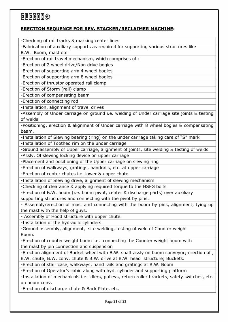
ERECTION SEQUENCE FOR REV. STACKER/RECLAIMER MACHINE:
-Checking of rail tracks & marking center lines
-Fabrication of auxiliary supports as required for supporting various structures like
B.W. Boom, mast etc.
-Erection of rail travel mechanism, which comprises of :
-Erection of 2 wheel drive/Non drive bogies
-Erection of supporting arm 4 wheel bogies
-Erection of supporting arm 8 wheel bogies
-Erection of thrustor operated rail clamp
-Erection of Storm (rail) clamp
-Erection of compensating beam
-Erection of connecting rod
-Installation, alignment of travel drives
-Assembly of Under carriage on ground i.e. welding of Under carriage site joints & testing
of welds
-Positioning, erection & alignment of Under carriage with 8 wheel bogies & compensating
beam.
-Installation of Slewing bearing (ring) on the under carriage taking care of “S” mark
-Installation of Toothed rim on the under carriage
-Ground assembly of Upper carriage, alignment of joints, site welding & testing of welds
-Assly. Of slewing locking device on upper carriage
-Placement and positioning of the Upper carriage on slewing ring
-Erection of walkways, gratings, handrails, etc. at upper carriage
-Erection of center chutes i.e. lower & upper chute
-Installation of Slewing drive, alignment of slewing mechanism
-Checking of clearance & applying required torque to the HSFG bolts
-Erection of B.W. boom (i.e. boom pivot, center & discharge parts) over auxiliary
supporting structures and connecting with the pivot by pins.
- Assembly/erection of mast and connecting with the boom by pins, alignment, tying up
the mast with the help of guys.
- Assembly of Hood structure with upper chute.
-Installation of the hydraulic cylinders.
-Ground assembly, alignment, site welding, testing of weld of Counter weight
Boom.
-Erection of counter weight boom i.e. connecting the Counter weight boom with
the mast by pin connection and suspension
-Erection alignment of Bucket wheel with B.W. shaft assly on boom conveyor; erection of ,
B.W. chute, B.W. conv. chute & B.W. drive at B.W. head structure; Buckets.
-Erection of stair case, walkways, hand rails and gratings at B.W. Boom
-Erection of Operator’s cabin along with hyd. cylinder and supporting platform
-Installation of mechanicals i.e. idlers, pulleys, return roller brackets, safety switches, etc.
on boom conv.
-Erection of discharge chute & Back Plate, etc.
Page 22 of 23
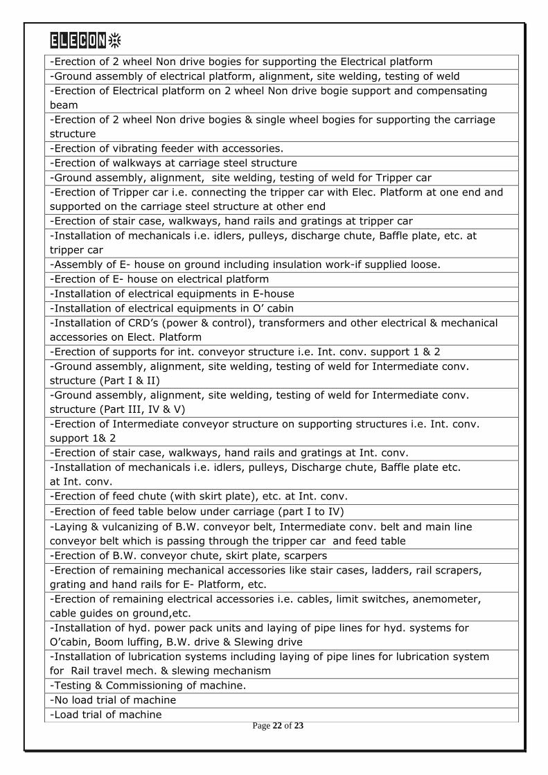
-Erection of 2 wheel Non drive bogies for supporting the Electrical platform
-Ground assembly of electrical platform, alignment, site welding, testing of weld
-Erection of Electrical platform on 2 wheel Non drive bogie support and compensating
beam
-Erection of 2 wheel Non drive bogies & single wheel bogies for supporting the carriage
structure
-Erection of vibrating feeder with accessories.
-Erection of walkways at carriage steel structure
-Ground assembly, alignment, site welding, testing of weld for Tripper car
-Erection of Tripper car i.e. connecting the tripper car with Elec. Platform at one end and
supported on the carriage steel structure at other end
-Erection of stair case, walkways, hand rails and gratings at tripper car
-Installation of mechanicals i.e. idlers, pulleys, discharge chute, Baffle plate, etc. at
tripper car
-Assembly of E- house on ground including insulation work-if supplied loose.
-Erection of E- house on electrical platform
-Installation of electrical equipments in E-house
-Installation of electrical equipments in O’ cabin
-Installation of CRD’s (power & control), transformers and other electrical & mechanical
accessories on Elect. Platform
-Erection of supports for int. conveyor structure i.e. Int. conv. support 1 & 2
-Ground assembly, alignment, site welding, testing of weld for Intermediate conv.
structure (Part I & II)
-Ground assembly, alignment, site welding, testing of weld for Intermediate conv.
structure (Part III, IV & V)
-Erection of Intermediate conveyor structure on supporting structures i.e. Int. conv.
support 1& 2
-Erection of stair case, walkways, hand rails and gratings at Int. conv.
-Installation of mechanicals i.e. idlers, pulleys, Discharge chute, Baffle plate etc.
at Int. conv.
-Erection of feed chute (with skirt plate), etc. at Int. conv.
-Erection of feed table below under carriage (part I to IV)
-Laying & vulcanizing of B.W. conveyor belt, Intermediate conv. belt and main line
conveyor belt which is passing through the tripper car and feed table
-Erection of B.W. conveyor chute, skirt plate, scarpers
-Erection of remaining mechanical accessories like stair cases, ladders, rail scrapers,
grating and hand rails for E- Platform, etc.
-Erection of remaining electrical accessories i.e. cables, limit switches, anemometer,
cable guides on ground,etc.
-Installation of hyd. power pack units and laying of pipe lines for hyd. systems for
O’cabin, Boom luffing, B.W. drive & Slewing drive
-Installation of lubrication systems including laying of pipe lines for lubrication system
for Rail travel mech. & slewing mechanism
-Testing & Commissioning of machine.
-No load trial of machine
-Load trial of machine
Page 23 of 23
** Above mentioned Erection sequence may be altered depending upon the availability of
Erection tools/tackles like cranes, lifting jacks, etc.
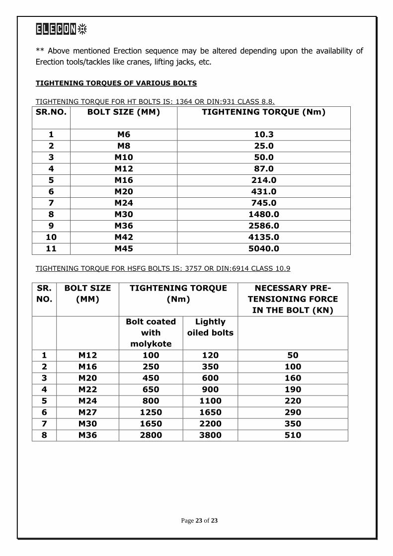
TIGHTENING TORQUES OF VARIOUS BOLTS
TIGHTENING TORQUE FOR HT BOLTS IS: 1364 OR DIN:931 CLASS 8.8.
SR.NO. BOLT SIZE (MM) TIGHTENING TORQUE (Nm)
1 M6 10.3
2 M8 25.0
3 M10 50.0
4 M12 87.0
5 M16 214.0
6 M20 431.0
7 M24 745.0
8 M30 1480.0
9 M36 2586.0
10 M42 4135.0
11 M45 5040.0
TIGHTENING TORQUE FOR HSFG BOLTS IS: 3757 OR DIN:6914 CLASS 10.9
SR.
NO.
BOLT SIZE
(MM)
TIGHTENING TORQUE
(Nm)
NECESSARY PRE-
TENSIONING FORCE
IN THE BOLT (KN)
Bolt coated
with
molykote
Lightly
oiled bolts
1 M12 100 120 50
2 M16 250 350 100
3 M20 450 600 160
4 M22 650 900 190
5 M24 800 1100 220
6 M27 1250 1650 290
7 M30 1650 2200 350
8 M36 2800 3800 510