Embed Size (px)
Citation preview

DISCLAIMER
ERCOT provides this “portable document format” (PDF) version of the Nodal Operating Guides for convenience only. This version of the document does not constitute and “official” version of the document. ERCOT is aware of certain formatting errors that occurred in tables and formulae when converting the document from MS Word format into PDF format and, therefore, you should not rely on that information. For more accurate references, please refer to the original versions of the document at 0Hhttp://www.ercot.com/mktrules/guides/noperating/cur.
PUBLIC
ERCOT Nodal Operating Guides
September 25, 2015

ERCOT Nodal Operating Guide Table of Contents
September 25, 2015

TABLE OF CONTENTS
ERCOT NODAL OPERATING GUIDES – SEPTEMBER 25, 2015 2
1 Overview .............................................................................................................................................................. 1 1.1 Document Purpose ............................................................................................................................ 1 1.2 Document Relationship ..................................................................................................................... 2 1.3 Process for Nodal Operating Guide Revision ................................................................................... 2
1.3.1 Introduction .............................................................................................................................. 2 1.3.2 Submission of a Nodal Operating Guide Revision Request ..................................................... 3 1.3.3 Operations Working Group ...................................................................................................... 3 1.3.4 Nodal Operating Guide Revision Procedure ............................................................................ 4 1.3.5 Urgent Requests ..................................................................................................................... 12 1.3.6 Nodal Operating Guide Revision Implementation ................................................................. 13
1.4 Definitions....................................................................................................................................... 14 A...................................................................................................................................................... 14 B ...................................................................................................................................................... 14 C ...................................................................................................................................................... 14 D...................................................................................................................................................... 15 E ...................................................................................................................................................... 15 F ...................................................................................................................................................... 15 G...................................................................................................................................................... 15 H...................................................................................................................................................... 15 I ....................................................................................................................................................... 16 J ....................................................................................................................................................... 16 K...................................................................................................................................................... 16 L ...................................................................................................................................................... 16 M ..................................................................................................................................................... 16 N...................................................................................................................................................... 16 O...................................................................................................................................................... 16 P ...................................................................................................................................................... 17 Q...................................................................................................................................................... 17 R ...................................................................................................................................................... 17 S ...................................................................................................................................................... 17 T ...................................................................................................................................................... 17 U...................................................................................................................................................... 18 V...................................................................................................................................................... 18 W ..................................................................................................................................................... 18 X...................................................................................................................................................... 18 Y...................................................................................................................................................... 18 Z ...................................................................................................................................................... 18
1.5 Operational Training ....................................................................................................................... 19 1.5.1 System Operator Training Objectives .................................................................................... 19 1.5.2 System Operator Training Requirements ............................................................................... 19 1.5.3 ERCOT Operations Training Seminar ................................................................................... 20 1.5.4 ERCOT Severe Weather Drill ................................................................................................ 20 1.5.5 Training Practices .................................................................................................................. 21 1.5.6 ERCOT Operator Certification Program ................................................................................ 21
2 System Operations and Control Requirements .................................................................................................. 1
2.1 Operational Duties ............................................................................................................................ 1 2.2 System Monitoring and Control ........................................................................................................ 3
2.2.1 Overview .................................................................................................................................. 3 2.2.2 Security Criteria ....................................................................................................................... 4 2.2.3 Response to Transient Voltage Disturbance ............................................................................ 5 2.2.4 Load Frequency Control .......................................................................................................... 5 2.2.5 Automatic Voltage Regulators ................................................................................................. 6 2.2.6 Power System Stabilizers ......................................................................................................... 6 2.2.7 Turbine Speed Governors ........................................................................................................ 8

TABLE OF CONTENTS
ERCOT NODAL OPERATING GUIDES – SEPTEMBER 25, 2015 3
2.2.8 Performance/Disturbance/Compliance Analysis ...................................................................... 9 2.2.9 Time Error and Time Synchronization ................................................................................... 10 2.2.10 Generation Resource Response Time Requirements ........................................................... 10
2.3 Ancillary Services ........................................................................................................................... 12 2.3.1 Responsive Reserve ............................................................................................................... 17 2.3.2 Non-Spinning Reserve Service .............................................................................................. 19
2.4 Outage Coordination ....................................................................................................................... 21 2.5 Reliability Unit Commitment .......................................................................................................... 21
2.5.1 Criteria for Removing Contingencies from the RUC Analyses ............................................. 21 2.6 Requirements for Under-Frequency Relaying ................................................................................ 22
2.6.1 Automatic Firm Load Shedding ............................................................................................. 22 2.6.2 Generators .............................................................................................................................. 23
2.7 System Voltage Profile ................................................................................................................... 24 2.7.1 Introduction ............................................................................................................................ 24 2.7.2 Maintaining Voltage Profile ................................................................................................... 24 2.7.3 Special Consideration for Nuclear Power Plants.................................................................... 26 2.7.4 Reactive Considerations for Generation Resources ............................................................... 26
2.8 Operation of Direct Current Ties .................................................................................................... 27 2.8.1 Inadvertent Energy Management ........................................................................................... 28
2.9 Voltage Ride-Through Requirements For Generation Resources ................................................... 28 2.9.1 Additional Voltage Ride-Through Requirements for Wind-Powered Generation Resources ........................................................................................................................................ 29
3 Resource Testing and Qualification Procedures ............................................................................................... 1 3.1 System Control Interfaces with ERCOT ........................................................................................... 1
3.1.1 Introduction .............................................................................................................................. 1 3.1.2 Compliance with Dispatch Instructions ................................................................................... 1
3.2 Qualified Scheduling Entities ........................................................................................................... 1 3.2.1 Operating Obligations .............................................................................................................. 1 3.2.2 Changes in Resource Status ..................................................................................................... 2 3.2.3 Regulatory Required Incident and Disturbance Reports .......................................................... 2 3.2.4 Ancillary Service Qualification and Testing Program ............................................................. 3
3.3 Resource Entities .............................................................................................................................. 4 3.3.1 Unit Capability Requirements .................................................................................................. 5 3.3.2 Unit Reactive Capability Requirements ................................................................................... 6 3.3.3 Resource Entity Responsibilities for Equipment Ratings....................................................... 10
3.4 Load Resource Testing Requirement .............................................................................................. 11 3.5 ERCOT Implementation ................................................................................................................. 11 3.6 Transmission Service Providers ...................................................................................................... 11 3.7 Transmission Operators .................................................................................................................. 12
3.7.1 Transmission Owner Responsibility for a Vegetation Management Program ....................... 13 3.7.2 Trasmission Service Provider Responsibilities for Equipment Ratings ................................. 13
3.8 Requirements for Reporting Sabotage Information ........................................................................ 14 4 Emergency Operation ......................................................................................................................................... 1
4.1 Introduction ....................................................................................................................................... 2 4.2 Communication Under Emergency Conditions ................................................................................ 2
4.2.1 Operating Condition Notice ..................................................................................................... 2 4.2.2 Advisory ................................................................................................................................... 3 4.2.3 Watch ....................................................................................................................................... 3 4.2.4 Emergency Notice .................................................................................................................... 4
4.3 Operation to Maintain Transmission System Security ...................................................................... 4 4.3.1 Real-Time and Short Term Planning ....................................................................................... 5
4.4 Block Load Transfers between ERCOT and Non-ERCOT System .................................................. 5 4.5 Energy Emergency Alert (EEA) ....................................................................................................... 5
4.5.1 General ..................................................................................................................................... 5

TABLE OF CONTENTS
ERCOT NODAL OPERATING GUIDES – SEPTEMBER 25, 2015 4
4.5.2 Operating Procedures ............................................................................................................... 6 4.5.3 Implementation ........................................................................................................................ 7
4.6 Black Start Service .......................................................................................................................... 14 4.6.1 Principles ................................................................................................................................ 15 4.6.2 Strategies ................................................................................................................................ 15 4.6.3 Priorities ................................................................................................................................. 16 4.6.4 Responsibilities ...................................................................................................................... 17 4.6.5 Black Start Emergency Back Up Communication Facilities Criteria .................................... 19
4.7 Geomagnetic Operational Preparedness for Geomagnetic Disturbances ........................................ 20 4.7.1 Monitoring and Dissemination of Space Weather Information .............................................. 20 4.7.2 Development and Submission of TO GMD Operating Procedures or Processes ................... 20 4.7.3 ERCOT’s Operating Plan and Review of TO GMD Operating Procedures or Processes ...... 21
4.8 Responsive Reserve Service During Scarcity Conditions…………………………………………23 4.8.1 Responsive Reserve Service Manual Deployment…………………………………………..23 4.8.2 Responsive Reserve Service Manual Recall…….……….………….………………………24 5 Network Operations Modeling Requirements .................................................................................................... 1
5.1 System Modeling Information .......................................................................................................... 1
6 Disturbance Monitoring and System Protection ................................................................................................ 1 6.1 Disturbance Monitoring Requirements ............................................................................................. 1
6.1.1 Introduction .............................................................................................................................. 1 6.1.2 Fault Recording Equipment ..................................................................................................... 1 6.1.3 Phasor Measurement Recording Equipment ............................................................................ 4 6.1.4 Equipment Reporting Requirements ........................................................................................ 6 6.1.5 Review Process ........................................................................................................................ 6
6.2 System Protective Relaying .............................................................................................................. 6 6.2.1 Introduction .............................................................................................................................. 6 6.2.2 Design and Operating Requirements for ERCOT System Facilities ........................................ 7 6.2.3 Performance Analysis Requirements for ERCOT System Facilities ....................................... 8 6.2.4 Protective Relay System Failure Response ............................................................................ 10 6.2.5 Maintenance and Testing Requirements for ERCOT System Facilities ................................ 11 6.2.6 Requirements and Recommendations for ERCOT System Facilities .................................... 12
7 Telemetry and Communication........................................................................................................................... 1 7.1 ERCOT Wide Area Network ............................................................................................................ 1
7.1.1 ERCOT Responsibilities .......................................................................................................... 1 7.1.2 QSE and TSP Responsibilities ................................................................................................. 2 7.1.3 Joint Responsibilities (Maintenance and Restoration) ............................................................. 5
7.2 ERCOT ICCP Interface .................................................................................................................... 5 7.2.1 Quality Codes ........................................................................................................................... 5 7.2.2 Metric of Availability ............................................................................................................... 5
7.3 Telemetry .......................................................................................................................................... 6 7.3.1 Data from ERCOT to QSEs ..................................................................................................... 6 7.3.2 Data from ERCOT to TSP ....................................................................................................... 6 7.3.3 Data from QSEs and TSPs to ERCOT ..................................................................................... 6 7.3.4 TSP and QSE Telemetry Restoration ....................................................................................... 7 7.3.5 General Telemetry Performance Criterion ............................................................................... 8
7.4 Calibration and Testing of Telemetry Responsibilities ..................................................................... 8 7.5 Competitive Renewable Energy Zone Circuits and Stations ............................................................ 8
8 Attachments 8A Black Start Info 8B Protection System Misoperation Report 8C Turbine Governor Speed Tests 8D Seasonal Unit Net Real Power Capability Verification 8E Black Start Plan Template 8F Seasonal Hydro Responsive Reserve Net Capability Verification

TABLE OF CONTENTS
ERCOT NODAL OPERATING GUIDES – SEPTEMBER 25, 2015 5
8G Load Resource Tests 8H Unit Alternative Fuel Capability
8I Black Start Resource Availabiity Test Form
9 Monitoring Programs ..................................................................................................................................... 1 9.1 QSE and Resource Monitoring Program ........................................................................................... 1
9.1.1 Testing ...................................................................................................................................... 1 9.1.2 Reactive Testing for Generation Resources ............................................................................. 1 9.1.3 Real-Time Data ........................................................................................................................ 2 9.1.4 Compliance with Valid Dispatch Instructions .......................................................................... 3 9.1.5 Resource Facilities Network Operations Model Update Implementation Monitor .................. 3 9.1.6 Resource Outage Reporting ..................................................................................................... 3 9.1.7 Backup Control for Resource Energy Deployment .................................................................. 4 9.1.8 Qualified Staffing Requirement ............................................................................................... 4 9.1.9 Automatic Voltage Regulator (AVR) ...................................................................................... 5 9.1.10 Current Operating Plan Metrics for QSEs .............................................................................. 6
9.2 TSP Monitoring Program .................................................................................................................. 6 9.2.1 Intentionally Left Blank ........................................................................................................... 6 9.2.2 Real-Time Data Monitor .......................................................................................................... 6 9.2.3 Transmission Outage Reporting ............................................................................................... 7 9.2.4 Transmission Service Provider (TSP) Network Operations Model Update Implementation Monitor ............................................................................................................................................. 8 9.2.5 Backup Control for TSPs ........................................................................................................ 8
9.3 ERCOT Monitoring Program ............................................................................................................ 9 9.3.1 Transmission Control ............................................................................................................... 9 9.3.2 System and Resource Control ................................................................................................ 12 9.3.3 Forecasting ............................................................................................................................. 13 9.3.4 System Operating Constraints ................................................................................................ 14 9.3.5 Network Operations Model Update Implementation Statistics .............................................. 14 9.3.6 Back-up Control Plan ............................................................................................................. 15 9.3.7 ERCOT Black Start Plan ........................................................................................................ 15 9.3.8 Computer and Communication Systems Real-Time Availability and Systems Security ....... 15 9.3.9 Voltage and Reactive Control Performance Monitoring ........................................................ 16
9.4 Ancillary Services Monitoring Program ......................................................................................... 17 9.4.1 Hydro Responsive Testing ..................................................................................................... 17 9.4.2 Black Start Service Requirements for TSPs, QSEs, and Generation Resources .................... 17 9.4.3 Resource-Specific Responsive Reserve Performance ............................................................ 17 9.4.4 Constant Frequency Control .................................................................................................. 18 9.4.5 Resource-specific Non-Spinning Reserve .............................................................................. 18
10 Market Data Transparency ........................................................................................................................ 1 10.1 Direct Current Tie Outage Information ............................................................................................. 1 10.2 Daily Grid Operations Report ........................................................................................................... 2
11 Constraint Management Plans and Special Protection Systems ........................................................ 1 11.1 Introduction ....................................................................................................................................... 1 11.2 Special Protection System ................................................................................................................. 1 11.2.1 Reporting of SPS Operations ................................................................................................. 4 11.3 Remedial Action Plan ....................................................................................................................... 5 11.3.1 Remedial Action Plan Process ............................................................................................... 6 11.4 Mitigation Plan .................................................................................................................................. 6 11.5 Pre-Contingency Action Plans .......................................................................................................... 7
11.5.1 Pre-Contingency Action Plan Process .................................................................................... 8 11.6 Temporary Outage Action Plan ........................................................................................................ 8

PUBLIC
ERCOT Nodal Operating Guides
Section 1: Overview
March 1, 2015


TABLE OF CONTENTS: SECTION 1
ERCOT NODAL OPERATING GUIDES – MARCH 1, 2015 PUBLIC
1 OVERVIEW ........................................................................................................................................................ 1-1 1.1 DOCUMENT PURPOSE ........................................................................................................................................ 1-1 1.2 DOCUMENT RELATIONSHIP ............................................................................................................................... 1-2 1.3 PROCESS FOR NODAL OPERATING GUIDE REVISION .......................................................................................... 1-2
1.3.1 Introduction ............................................................................................................................................. 1-2 1.3.2 Submission of a Nodal Operating Guide Revision Request ..................................................................... 1-3 1.3.3 Operations Working Group ..................................................................................................................... 1-3 1.3.4 Nodal Operating Guide Revision Procedure .......................................................................................... 1-4 1.3.5 Urgent Requests .................................................................................................................................... 1-12 1.3.6 Nodal Operating Guide Revision Implementation ................................................................................ 1-13
1.4 DEFINITIONS .................................................................................................................................................... 1-14 A .......................................................................................................................................................................... 1-14 B .......................................................................................................................................................................... 1-14 C .......................................................................................................................................................................... 1-14 D .......................................................................................................................................................................... 1-15 E .......................................................................................................................................................................... 1-15 F .......................................................................................................................................................................... 1-15 G .......................................................................................................................................................................... 1-15 H .......................................................................................................................................................................... 1-15 I............................................................................................................................................................................ 1-16 J ........................................................................................................................................................................... 1-16 K .......................................................................................................................................................................... 1-16 L ........................................................................................................................................................................... 1-16 M .......................................................................................................................................................................... 1-16 N .......................................................................................................................................................................... 1-17 O .......................................................................................................................................................................... 1-17 P .......................................................................................................................................................................... 1-17 Q .......................................................................................................................................................................... 1-17 R .......................................................................................................................................................................... 1-17 S ........................................................................................................................................................................... 1-17 T ........................................................................................................................................................................... 1-17 U .......................................................................................................................................................................... 1-18 V .......................................................................................................................................................................... 1-18 W .......................................................................................................................................................................... 1-18 X .......................................................................................................................................................................... 1-18 Y ........................................................................................................................................................................... 1-18 Z ........................................................................................................................................................................... 1-19
1.5 OPERATIONAL TRAINING ................................................................................................................................. 1-20 1.5.1 System Operator Training Objectives ................................................................................................... 1-20 1.5.2 System Operator Training Requirements .............................................................................................. 1-20 1.5.3 ERCOT Operations Training Seminar .................................................................................................. 1-21 1.5.4 ERCOT Severe Weather Drill ............................................................................................................... 1-21 1.5.5 Training Practices ................................................................................................................................. 1-22 1.5.6 ERCOT Operator Certification Program .............................................................................................. 1-22


SECTION 1: OVERVIEW
ERCOT NODAL OPERATING GUIDES – MARCH 1, 2015 1-1 PUBLIC
1 OVERVIEW
1.1 Document Purpose
(1) These ERCOT Operating Guides supplement the Protocols. The Operating Guides provide more detail and establish additional operating requirements for those organizations and Entities operating in, or potentially impacting the reliability of the ERCOT Transmission Grid in the ERCOT Region, as shown below in Figure 1, ERCOT Regional Map.
Figure 1 – ERCOT Regional Map
(2) The title “Operating Guide” is not to be construed as presenting merely a recommendation. Organizations and Entities are obligated to comply with the Operating Guides. Specific practices described in the Operating Guides for the ERCOT Region are consistent with North American Electric Reliability Corporation (NERC) Reliability Standards and the Protocols.

SECTION 1: OVERVIEW
ERCOT NODAL OPERATING GUIDES – MARCH 1, 2015 1-2 PUBLIC
1.2 Document Relationship
(1) These Operating Guides are written to be consistent with the Protocols and to implement the North American Electric Reliability Corporation (NERC) Reliability Standards. The Protocols supersede these Operating Guides. The Public Utility Commission of Texas (PUCT) rules contain additional requirements for ERCOT and connected Entities.
(2) For application in the ERCOT Region, some NERC Reliability Standards must be adapted to fit the unique characteristics of ERCOT. Defined terminology for NERC Regional Variances, if any, is detailed in the NERC Reliability Standards.
1.3 Process for Nodal Operating Guide Revision
1.3.1 Introduction
(1) A request to make additions, edits, deletions, revisions, or clarifications to these Operating Guides, including any attachments and exhibits to these Operating Guides, is called a Nodal Operating Guide Revision Request (NOGRR). Except as specifically provided in other sections of these Operating Guides, Section 1.3, Process for Nodal Operating Guide Revision, shall be followed for all NOGRRs. ERCOT Members, Market Participants, Public Utility Commission of Texas (PUCT) Staff, Texas Reliability Entity (Texas RE) Staff, ERCOT, and any other Entities are required to utilize the process described herein prior to requesting, through the PUCT or other Governmental Authority, that ERCOT make a change to these Operating Guides, except for good cause shown to the PUCT or other Governmental Authority.
(2) The “next regularly scheduled meeting” of the Operations Working Group (OWG), the Reliability and Operations Subcommittee (ROS), the Technical Advisory Committee (TAC), or ERCOT Board shall mean the next regularly scheduled meeting for which required Notice can be timely given regarding the item(s) to be addressed, as specified in the appropriate ERCOT Board or committee procedures.
(3) Throughout the Operating Guides, references are made to the ERCOT Protocols. ERCOT Protocols supersede the Operating Guides and any NOGRR must be compliant with the Protocols. The ERCOT Protocols are subject to the revision process outlined in Protocol Section 21, Revision Request Process.
(4) ERCOT may make non-substantive corrections at any time during the processing of a particular NOGRR. Under certain circumstances, however, the Operating Guides can also be revised by ERCOT rather than using the NOGRR process outlined in Section 1.3.
(a) This type of revision is referred to as an “Administrative NOGRR” or “Administrative Changes” and shall consist of non-substantive corrections, such as typos (excluding grammatical changes), internal references (including table of contents), improper use of acronyms, references to ERCOT Protocols, PUCT Substantive Rules, the Public Utility Regulatory Act (PURA), North American

SECTION 1: OVERVIEW
ERCOT NODAL OPERATING GUIDES – MARCH 1, 2015 1-3 PUBLIC
Electric Reliability Corporation (NERC) regulations, Federal Energy Regulatory Commission (FERC) rules, etc., and revisions for the purpose of maintaining consistency between Section 1.3, Process for Nodal Operating Guide Revision, and Protocol Section 21, Revision Request Process. Additionally, updates to the ERCOT Load Shed Table in Section 4.5.3.4, Load Shed Obligation, may also be processed as Administrative NOGRRs.
(b) ERCOT shall post such Administrative NOGRRs to the ERCOT website and distribute the NOGRR to the OWG at least ten Business Days before implementation. If no Entity submits comments to the Administrative NOGRR in accordance with paragraph (1) of Section 1.3.4.3, Operations Working Group Review and Action, ERCOT shall implement it according to paragraph (4) of Section 1.3.6, Nodal Operating Guide Revision Implementation. If any ERCOT Member, Market Participant, PUCT Staff, Texas RE Staff or ERCOT submits comments to the Administrative NOGRR, then it shall be processed in accordance with the NOGRR process outlined in Section 1.3.
1.3.2 Submission of a Nodal Operating Guide Revision Request
The following Entities may submit a NOGRR:
(a) Any Market Participant;
(b) Any ERCOT Member;
(c) PUCT Staff;
(d) Texas RE Staff;
(e) ERCOT; and
(f) Any other Entity that meets the following qualifications:
(i) Resides (or represent residents) in Texas or operates in the Texas electricity market; and
(ii) Demonstrates that Entity (or those it represents) is affected by the Customer Registration or Renewable Energy Credit (REC) Trading Program sections of the ERCOT Protocols.
1.3.3 Operations Working Group
(1) The OWG shall review and recommend action on formally submitted NOGRRs, provided that:
(a) OWG meetings are open to ERCOT, ERCOT Members, Market Participants, Texas RE Staff, and PUCT Staff; and

SECTION 1: OVERVIEW
ERCOT NODAL OPERATING GUIDES – MARCH 1, 2015 1-4 PUBLIC
(b) Each Market Segment is allowed to participate.
(2) Where additional expertise is needed, the OWG may request that ROS refer a NOGRR to existing TAC subcommittees, working groups or task forces for review and comment on the NOGRR. Suggested modifications or alternative modifications if a consensus recommendation is not achieved by a non-voting working group or task force, to the NOGRR should be submitted by the chair or the chair’s designee on behalf of the commenting subcommittee, working group or task force as comments on the NOGRR for consideration by OWG. However, the OWG shall retain ultimate responsibility for the processing of all NOGRRs.
(3) The OWG shall ensure that the Operating Guides are compliant with the ERCOT Protocols. As such, the OWG will monitor all changes to the ERCOT Protocols and initiate any NOGRRs necessary to bring the Operating Guides in conformance with the ERCOT Protocols. The OWG will also initiate a Nodal Protocol Revision Request (NPRR) if such a change is necessary to accommodate a proposed NOGRR prior to proceeding with that NOGRR.
(4) ERCOT shall consult with the OWG chair to coordinate and establish the meeting schedule for the OWG. The OWG shall meet at least once per month, unless no NOGRRs were submitted during the prior 24 days, and shall ensure that reasonable advance notice of each meeting, including the meeting agenda, is posted on the ERCOT website.
1.3.4 Nodal Operating Guide Revision Procedure
1.3.4.1 Review and Posting of Nodal Operating Guide Revision Requests
(1) NOGRRs shall be submitted electronically to ERCOT by completing the designated form provided on the ERCOT website. ERCOT shall provide an electronic return receipt response to the submitter upon receipt of the NOGRR.
(2) The NOGRR shall include the following information:
(a) Description of requested revision and reason for suggested change;
(b) Impacts and benefits of the suggested change on ERCOT market structure, ERCOT operations, and Market Participants, to the extent that the submitter may know this information;
(c) Impact Analysis (applicable only for a NOGRR submitted by ERCOT);
(d) List of affected Operating Guide sections and subsections;
(e) General administrative information (organization, contact name, etc.); and
SECTION 1: OVERVIEW
ERCOT NODAL OPERATING GUIDES – MARCH 1, 2015 1-5 PUBLIC
(f) Suggested language for requested revision.
(3) ERCOT shall evaluate the NOGRR for completeness and shall notify the submitter, within five Business Days of receipt, if the NOGRR is incomplete, including the reasons for such status. ERCOT may provide information to the submitter that will correct the NOGRR and render it complete. An incomplete NOGRR shall not receive further consideration until it is completed. In order to pursue the NOGRR, a submitter must submit a completed version of the NOGRR.
(4) If a submitted NOGRR is complete or once a NOGRR is completed, ERCOT shall post the NOGRR on the ERCOT website and distribute to the OWG within three Business Days.
1.3.4.2 Withdrawal of a Nodal Operating Guide Revision Request
(1) A submitter may withdraw or request to withdraw a NOGRR by submitting a completed Request for Withdrawal form provided on the ERCOT website. ERCOT shall post the submitter’s Request for Withdrawal on the ERCOT website within three Business Days of submittal.
(2) The submitter of a NOGRR may withdraw the NOGRR at any time before the OWG recommends approval of the NOGRR. If the OWG has recommended approval of the NOGRR, the Request for Withdrawal must be approved by ROS if the NOGRR has not yet been recommended for approval by ROS.
(3) If ROS has recommended approval of the NOGRR, the Request for Withdrawal must be approved by TAC if the NOGRR has not yet been approved or recommended for approval by TAC.
(4) If TAC has recommended approval of a NOGRR that requires an ERCOT project for implementation, the Request for Withdrawal must be approved by the ERCOT Board if the NOGRR has not yet been approved by the ERCOT Board.
(5) Once a NOGRR that requires an ERCOT project for implementation is approved by the ERCOT Board or a NOGRR that does not require an ERCOT project for implementation is approved by TAC, such NOGRR cannot be withdrawn.
1.3.4.3 Operations Working Group Review and Action
(1) Any ERCOT Member, Market Participant, PUCT Staff, Texas RE Staff or ERCOT may comment on the NOGRR.
(2) To receive consideration, comments must be delivered electronically to ERCOT in the designated format provided on the ERCOT website within 14 days from the posting date of the NOGRR. Comments submitted after the 14 day comment period may be considered at the discretion of OWG after these comments have been posted. Comments

SECTION 1: OVERVIEW
ERCOT NODAL OPERATING GUIDES – MARCH 1, 2015 1-6 PUBLIC
submitted in accordance with the instructions on the ERCOT website, regardless of date of submission, shall be posted to the ERCOT website and distributed electronically to the OWG within three Business Days of submittal.
(3) The OWG shall consider the NOGRR at its next regularly scheduled meeting after the end of the 14 day comment period. At such meeting, the OWG may take action on the NOGRR. In considering action on a NOGRR, the OWG may:
(a) Recommend approval of the NOGRR as submitted or as modified;
(b) Recommend rejection of the NOGRR;
(c) If no consensus can be reached on the NOGRR, present options for ROS consideration;
(d) Defer decision on the NOGRR; or
(e) Recommend that ROS refer the NOGRR to a subcommittee, working group or task force as provided in Section 1.3.3, Operations Working Group.
(4) Within three Business Days after OWG takes action, ERCOT shall issue an OWG Report reflecting the OWG action and post it to the ERCOT website. The OWG Report shall contain the following items:
(a) Identification of submitter;
(b) Operating Guide language recommended by the OWG, if applicable;
(c) Identification of authorship of comments, if applicable;
(d) Proposed effective date of the NOGRR;
(e) Recommended priority and rank for any NOGRRs requiring an ERCOT project for implementation; and
(f) OWG action.
1.3.4.4 Comments to the Operations Working Group Report
(1) Any ERCOT Member, Market Participant, PUCT Staff, Texas RE Staff, or ERCOT may comment on the OWG Report. Within three Business Days of receipt of comments related to the OWG Report, ERCOT shall post such comments to the ERCOT website. Comments submitted in accordance with the instructions on the ERCOT website, regardless of date of submission, shall be posted on the ERCOT website within three Business Days of submittal.
(2) The comments on the OWG Report will be considered at the next regularly scheduled OWG or ROS meeting where the NOGRR is being considered.

SECTION 1: OVERVIEW
ERCOT NODAL OPERATING GUIDES – MARCH 1, 2015 1-7 PUBLIC
1.3.4.5 Nodal Operating Guide Revision Request Impact Analysis
(1) ERCOT shall submit to OWG an initial Impact Analysis based on the original language in the NOGRR with any ERCOT-sponsored NOGRR. The initial Impact Analysis will provide OWG with guidance as to what ERCOT computer systems, operations, or business functions could be affected by the NOGRR as submitted.
(2) If OWG recommends approval of a NOGRR, ERCOT shall prepare an Impact Analysis based on the proposed language in the OWG Report. If ERCOT has already prepared an Impact Analysis, ERCOT shall update the existing Impact Analysis, if necessary, to accommodate the language recommended for approval in the OWG Report.
(3) The Impact Analysis shall assess the impact of the proposed NOGRR on ERCOT staffing, computer systems, operations, or business functions and shall contain the following information:
(a) An estimate of any cost and budgetary impacts to ERCOT for both implementation and ongoing operations;
(b) The estimated amount of time required to implement the NOGRR;
(c) The identification of alternatives to the NOGRR that may result in more efficient implementation; and
(d) The identification of any manual workarounds that may be used as an interim solution and estimated costs of the workaround.
(4) Unless a longer review period is warranted due to the complexity of the proposed OWG Report, ERCOT shall issue an Impact Analysis for a NOGRR for which OWG has recommended approval of prior to the next regularly scheduled OWG meeting. ERCOT shall post the results of the completed Impact Analysis on the ERCOT website. If a longer review period is required by ERCOT to complete an Impact Analysis, ERCOT shall submit comments with a schedule for completion of the Impact Analysis to the OWG.
1.3.4.6 Operations Working Group Review of Impact Analysis
(1) After ERCOT posts the results of the Impact Analysis, OWG shall review the Impact Analysis at its next regularly scheduled meeting. OWG may revise its OWG Report after considering the information included in the Impact Analysis or additional comments received on the OWG Report.
(2) After consideration of the Impact Analysis and the OWG Report, ERCOT shall issue a revised OWG Report and post it on the ERCOT website within three Business Days of the OWG consideration of the Impact Analysis and the OWG Report. If OWG revises the proposed NOGRR, ERCOT shall update the Impact Analysis, if necessary, and issue the updated Impact Analysis to ROS. If a longer review period is required for ERCOT to

SECTION 1: OVERVIEW
ERCOT NODAL OPERATING GUIDES – MARCH 1, 2015 1-8 PUBLIC
update the Impact Analysis, ERCOT shall submit comments with a schedule for completion of the Impact Analysis to ROS.
(3) If the NOGRR requires an ERCOT project for implementation, at the same meeting, OWG shall assign a recommended priority and rank for the associated project.
1.3.4.7 Reliability and Operations Subcommittee Vote
(1) ROS shall consider any NOGRRs that OWG has submitted to ROS for consideration for which both an OWG Report and an Impact Analysis (as updated if modified by OWG under Section 1.3.4.6, Operations Working Group Review of Impact Analysis) have been posted on the ERCOT website. The following information must be included for each NOGRR considered by ROS:
(a) The OWG Report and Impact Analysis; and
(b) Any comments timely received in response to the OWG Report.
(2) The quorum and voting requirements for ROS action are set forth in the Technical Advisory Committee Procedures. In considering action on an OWG Report, ROS shall:
(a) Recommend approval of the NOGRR as recommended in the OWG Report or as modified by ROS;
(b) Reject the NOGRR;
(c) Defer decision on the NOGRR;
(d) Remand the NOGRR to the OWG with instructions; or
(e) Refer the NOGRR to another ROS working group or task force or another TAC subcommittee with instructions.
(3) If a motion is made to recommend approval of a NOGRR and that motion fails, the NOGRR shall be deemed rejected by ROS unless at the same meeting ROS later votes to recommend approval of, defer, remand, or refer the NOGRR. If a motion to recommend approval of a NOGRR fails via email vote according to the Technical Advisory Committee Procedures, the NOGRR shall be deemed rejected by ROS unless at the next regularly scheduled ROS meeting or in a subsequent email vote prior to the meeting, ROS votes to recommend approval of, defer, remand, or refer the NOGRR. The rejected NOGRR shall be subject to appeal pursuant to Section 1.3.4.12, Appeal of Action.
(4) Within three Business Days after ROS takes action on the NOGRR, ERCOT shall issue a ROS Report reflecting the ROS action and post it on the ERCOT website. The ROS Report shall contain the following items:
(a) Identification of the submitter of the NOGRR;

SECTION 1: OVERVIEW
ERCOT NODAL OPERATING GUIDES – MARCH 1, 2015 1-9 PUBLIC
(b) Modified Operating Guide language proposed by ROS, if applicable;
(c) Identification of the authorship of comments, if applicable;
(d) Proposed effective date(s) of the NOGRR;
(e) Recommended priority and rank for any NOGRR requiring an ERCOT project for implementation;
(f) OWG action; and
(g) ROS action.
1.3.4.8 ERCOT Impact Analysis Based on Reliability and Operations Subcommittee Report
ERCOT shall review the ROS Report and, if necessary, update the Impact Analysis as soon as practicable. ERCOT shall issue the updated Impact Analysis, if applicable, to TAC and post it on the ERCOT website. If a longer review period is required for ERCOT to update the Impact Analysis, ERCOT shall submit comments with a schedule for completion of the Impact Analysis to TAC.
1.3.4.9 PRS Review of Project Prioritization
At the next regularly scheduled Protocol Revision Subcommittee (PRS) meeting after ROS recommends approval of a NOGRR that requires an ERCOT project for implementation, the PRS shall assign a recommended priority and rank for the associated project.
1.3.4.10 Technical Advisory Committee Vote
(1) TAC shall consider any NOGRR that ROS has submitted to TAC for consideration for which both a ROS Report and an Impact Analysis (as updated if modified by ROS under Section 1.3.4.8, ERCOT Impact Analysis Based on Reliability and Operations Subcommittee Report) have been posted on the ERCOT website. The following information must be included for each NOGRR considered by TAC:
(a) The ROS Report and Impact Analysis;
(b) The recommended priority and rank, if an ERCOT project is required; and
(c) Any comments timely received in response to the ROS Report.
(2) The quorum and voting requirements for TAC action are set forth in the Technical Advisory Committee Procedures. In considering action on a ROS Report, TAC shall:

SECTION 1: OVERVIEW
ERCOT NODAL OPERATING GUIDES – MARCH 1, 2015 1-10 PUBLIC
(a) Approve the NOGRR as recommended in the ROS Report or as modified by TAC, if the NOGRR does not require an ERCOT project for implementation;
(b) Recommend approval of the NOGRR as recommended in the ROS Report or as modified by TAC, including modification of the recommended priority and rank if the NOGRR requires an ERCOT project for implementation;
(c) Reject the NOGRR;
(d) Defer decision on the NOGRR;
(e) Remand the NOGRR to ROS with instructions; or
(f) Refer the NOGRR to another TAC subcommittee or a TAC working group or task force with instructions.
(3) If a motion is made to approve or recommend approval of a NOGRR and that motion fails, the NOGRR shall be deemed rejected by TAC unless at the same meeting TAC later votes to approve, recommend approval of, defer, remand, or refer the NOGRR. If a motion to approve or recommend approval of an NOGRR fails via email vote according to the Technical Advisory Committee Procedures, the NOGRR shall be deemed rejected by TAC unless at the next regularly scheduled TAC meeting or in a subsequent email vote prior to such meeting, TAC votes to approve, recommend approval of, defer, remand, or refer the NOGRR. The rejected NOGRR shall be subject to appeal pursuant to Section 1.3.4.12, Appeal of Action
(4) Within three Business Days after TAC takes action on a NOGRR, ERCOT shall issue a TAC Report reflecting the TAC action and post it on the ERCOT website. The TAC Report shall contain the following items:
(a) Identification of the submitter of the NOGRR;
(b) Modified Nodal Operating Guide language proposed by TAC, if applicable;
(c) Identification of the authorship of comments, if applicable;
(d) Proposed effective date(s) of the NOGRR;
(e) Priority and rank for any NOGRR requiring an ERCOT project for implementation;
(f) ROS action;
(g) TAC action; and
(h) ERCOT’s position for any NOGRR requiring an ERCOT project for implementation.

SECTION 1: OVERVIEW
ERCOT NODAL OPERATING GUIDES – MARCH 1, 2015 1-11 PUBLIC
(5) If TAC recommends approval of a NOGRR requiring an ERCOT project for implementation, ERCOT shall forward the TAC Report to the ERCOT Board for consideration pursuant to Section 1.3.4.11, ERCOT Board Vote.
(6) The TAC chair shall report the results of all votes by TAC related to NOGRRs to the ERCOT Board at its next regularly scheduled meeting.
1.3.4.11 ERCOT Board Vote
(1) For any NOGRR requiring an ERCOT project for implementation, upon issuance of a TAC Report and Impact Analysis to the ERCOT Board, the ERCOT Board shall review the TAC Report and the Impact Analysis at the following month’s regularly scheduled meeting. For Urgent NOGRRs, the ERCOT Board shall review the TAC Report and Impact Analysis at the next regularly scheduled meeting, unless a special meeting is required due to the urgency of the NOGRR.
(2) The quorum and voting requirements for ERCOT Board action are set forth in the ERCOT Bylaws. In considering action on a TAC Report, the ERCOT Board shall:
(a) Approve the NOGRR as recommended in the TAC Report or as modified by the ERCOT Board;
(b) Reject the NOGRR;
(c) Defer decision on the NOGRR; or
(d) Remand the NOGRR to TAC with instructions.
(3) If a motion is made to approve a NOGRR and that motion fails, the NOGRR shall be deemed rejected by the ERCOT Board unless at the same meeting the ERCOT Board later votes to approve, defer, or remand the NOGRR. The rejected NOGRR shall be subject to appeal pursuant to Section 1.3.4.12, Appeal of Action.
(4) Within three Business Days after the ERCOT Board takes action on a NOGRR, ERCOT shall issue a Board Report reflecting the ERCOT Board action and post it on the ERCOT website.
1.3.4.12 Appeal of Action
(1) Any ERCOT Member, Market Participant, PUCT Staff, Texas RE Staff or ERCOT may appeal an OWG action to recommend rejection of, defer, or recommend referral of a NOGRR directly to ROS. Such appeal to the ROS must be submitted electronically to ERCOT by completing the designated form provided on the ERCOT website within seven days after the date of the relevant OWG appealable event. ERCOT shall reject appeals made after that time. ERCOT shall post appeals on the ERCOT website within three Business Days of receiving the appeal. Appeals shall be heard at the next regularly

SECTION 1: OVERVIEW
ERCOT NODAL OPERATING GUIDES – MARCH 1, 2015 1-12 PUBLIC
scheduled ROS meeting that is at least seven days after the date of the requested appeal. An appeal of a NOGRR to ROS suspends consideration of the NOGRR until the appeal has been decided by ROS.
(2) Any ERCOT Member, Market Participant, PUCT Staff, Texas RE Staff, or ERCOT may appeal a ROS action to reject, defer, remand or refer a NOGRR directly to TAC. Such appeal to the TAC must be submitted electronically to ERCOT by completing the designated form provided on the ERCOT website within seven days after the date of the relevant ROS appealable event. ERCOT shall reject appeals made after that time. ERCOT shall post appeals on the ERCOT website within three Business Days of receiving the appeal. Appeals shall be heard at the next regularly scheduled TAC meeting that is at least seven days after the date of the requested appeal. An appeal of a NOGRR to TAC suspends consideration of the NOGRR until the appeal has been decided by TAC.
(3) Any ERCOT Member, Market Participant, PUCT Staff, Texas RE Staff or ERCOT may appeal a TAC action to approve, reject, defer, remand, or refer a NOGRR directly to the ERCOT Board. Appeals to the ERCOT Board shall be processed in accordance with the ERCOT Board Policies and Procedures. An appeal of a NOGRR to the ERCOT Board suspends consideration of the NOGRR until the appeal has been decided by the ERCOT Board.
(4) Any ERCOT Member, Market Participant, PUCT Staff or Texas RE Staff may appeal any decision of the ERCOT Board regarding a NOGRR to the PUCT or other Governmental Authority. Such appeal to the PUCT or other Governmental Authority must be made within any deadline prescribed by the PUCT or other Governmental Authority, but in any event no later than 35 days of the date of the relevant ERCOT Board appealable event. Notice of any appeal to the PUCT or other Governmental Authority must be provided, at the time of the appeal, to ERCOT’s General Counsel. If the PUCT or other Governmental Authority rules on the NOGRR, ERCOT shall post the ruling on the ERCOT website.
1.3.5 Urgent Requests
(1) The party submitting a NOGRR may request that the NOGRR be considered on an urgent timeline (“Urgent”) only when the submitter can reasonably show that an existing Nodal Operating Guide provision is impairing or could imminently impair ERCOT System reliability or wholesale or retail market operations, or is causing or could imminently cause a discrepancy between a Settlement formula and a provision of the ERCOT Protocols.
(2) ROS may designate the NOGRR for Urgent consideration if a submitter requests Urgent status or upon valid motion in a regularly scheduled meeting of the ROS. Criteria for designating a NOGRR as Urgent are that the NOGRR requires immediate attention due to:

SECTION 1: OVERVIEW
ERCOT NODAL OPERATING GUIDES – MARCH 1, 2015 1-13 PUBLIC
(a) Serious concerns about ERCOT System reliability or market operations under the unmodified language; or
(b) The crucial nature of a Settlement activity conducted pursuant to any Settlement formula.
(3) ERCOT shall prepare an Impact Analysis for Urgent NOGRRs as soon as practicable.
(4) ROS or the OWG shall consider the Urgent NOGRR and Impact Analysis, if available, at the next regularly scheduled ROS or OWG meeting, or at a special meeting called by the ROS or OWG chair to consider the Urgent NOGRR.
(5) If the submitter desires to further expedite processing of the NOGRR, a request for voting via email may be submitted to the ROS chair. The ROS chair may grant the request for voting via email. Such voting shall be conducted pursuant to the Technical Advisory Committee Procedures. If ROS recommends approval of an Urgent NOGRR, ERCOT shall issue a ROS Report reflecting the ROS action and post it on the ERCOT website within three Business Days after ROS takes action. The TAC chair may request action from TAC to accelerate or alter the procedures described herein, as needed, to address the urgency of the situation.
(6) Any NOGRRs that take effect pursuant to an Urgent request shall be subject to an Impact Analysis pursuant to Section 1.3.4.8, ERCOT Impact Analysis Based on Reliability and Operations Subcommittee Report, and TAC consideration pursuant to Section 1.3.4.10, Technical Advisory Committee Vote.
1.3.6 Nodal Operating Guide Revision Implementation
(1) For NOGRRs that do not require an ERCOT project for implementation, upon TAC approval, ERCOT shall implement NOGRRs on the first day of the month following TAC approval, unless otherwise provided in the TAC Report for the approved NOGRR.
(2) For NOGRRs that require an ERCOT project for implementation, upon ERCOT Board approval, ERCOT shall implement NOGRRs on the first day of the month following ERCOT Board approval, unless otherwise provided in the Board Report for the approved NOGRR.
(3) For NOGRRs for which an effective date other than the first day of the month following TAC or ERCOT Board approval, as applicable, is provided, the ERCOT Impact Analysis shall provide an estimated implementation date and ERCOT shall provide notice as soon as practicable, but no later than ten days prior to the actual implementation, unless a different notice period is required in the TAC or Board Report, as applicable, for the approved NOGRR.
(4) ERCOT shall implement an Administrative NOGRR on the first day of the month following the end of the ten Business Day posting requirement outlined in Section 1.3.1, Introduction.

SECTION 1: OVERVIEW
ERCOT NODAL OPERATING GUIDES – MARCH 1, 2015 1-14 PUBLIC
1.4 Definitions
A primary list of definitions is contained within Protocol Section 2, Definitions and Acronyms. Additional definitions that apply specifically to these Operating Guides are listed below. It is essential to the reliability of the ERCOT Transmission Grid that all appropriate personnel use and understand the same terms in their daily operations. The definitions in this Section are intended to enable ERCOT, Qualified Scheduling Entities (QSEs), and Transmission Operators (TOs) to effectively communicate on an ongoing basis.
LINKS TO DEFINITIONS:
A, B, C, D, E, F, G, H, I, J, K, L, M, N, O, P, Q, R, S, T, U, V, W, X, Y, Z;
A [Back to Top]
Automatic Generation Control (AGC)
Application that receives signals from ERCOT for Regulation deployment and Responsive Reserve (RRS) deployment and causes Generation Resources providing these Ancillary Services to respond in accordance with their participation factor and ramp rate to meet the received deployments.
B [Back to Top]
C [Back to Top]
Capacitor
Static device which produces reactive power (VAr source) for voltage control when energized (tends to raise voltage).
Cranking Path
A set of elements in the ERCOT System that establishes an electrical path from a contracted Black Start Resource to a designated next start Resource.

SECTION 1: OVERVIEW
ERCOT NODAL OPERATING GUIDES – MARCH 1, 2015 1-15 PUBLIC
D [Back to Top]
Designated Agent
Any Entity that is authorized to perform actions or functions on behalf of another Entity.
E [Back to Top]
F [Back to Top]
G [Back to Top]
Generator Reactive Power Sign/Direction Terminology
(1) Lagging power factor operating condition is when MVAr flow is out of the Generation Resource (overexcited generator) and is considered to be positive (+) flow, i.e., in the same direction as MW power flow. The generator is producing MVArs.
(2) Leading power factor operating condition is when MVAr flow is into the Generation Resource (underexcited generator) and is considered to be negative (-) flow, i.e., in the opposite direction as MW power flow. The generator is absorbing MVArs.
Geomagnetic Disturbance (GMD)
A disturbance of the earth’s magnetic field caused by the interaction of that field with the effects of solar storms. These GMDs may result in induced currents that may negatively affect power system equipment.
H [Back to Top]

SECTION 1: OVERVIEW
ERCOT NODAL OPERATING GUIDES – MARCH 1, 2015 1-16 PUBLIC
I [Back to Top]
Inadvertent Energy
The difference between the ERCOT System actual metered value and the ERCOT System scheduled energy.
Intercompany Connections
The connection between two or more independent transmission companies.
Intra-Company
Occurring within or between the branches of a single company.
Island
An electrically separated portion of the ERCOT System with independent frequency, generation and Load.
J [Back to Top]
K [Back to Top]
L [Back to Top]
M [Back to Top]

SECTION 1: OVERVIEW
ERCOT NODAL OPERATING GUIDES – MARCH 1, 2015 1-17 PUBLIC
N [Back to Top]
O [Back to Top]
P [Back to Top]
Q [Back to Top]
R [Back to Top]
S [Back to Top]
Synchronization Corridors
A predetermined section of the ERCOT Transmission Grid that may be utilized to synchronize Islands after a Partial Blackout or Blackout.
T [Back to Top]
Telemetry
The measured quantity or quality (e.g., open/closed, amps, volts, MW, MVAr, MVA) and transmitting the result to a remote location for indication or recording.

SECTION 1: OVERVIEW
ERCOT NODAL OPERATING GUIDES – MARCH 1, 2015 1-18 PUBLIC
Time Error
An accumulated time difference between ERCOT System time and the time standard. Time error is caused by a deviation in ERCOT average frequency from 60.0 Hz.
Transmission Line Terminal Sign/Direction Terminology
(1) MW or MVAr flow out of the bus is considered to be positive (+) flow.
(2) MW or MVAr flow into the bus is considered to be negative (-) flow.
Transmission Operator (TO)
Entity responsible for the safe and reliable operation of its own portion or designated portion of the ERCOT Transmission System. Every Transmission Service Provider (TSP) or Distribution Service Provider (DSP) in the ERCOT Region shall either register as a TO, or designate a TO as its representative and with the authority to act on its behalf.
U [Back to Top]
V [Back to Top]
W [Back to Top]
X [Back to Top]
Y [Back to Top]

SECTION 1: OVERVIEW
ERCOT NODAL OPERATING GUIDES – MARCH 1, 2015 1-19 PUBLIC
Z [Back to Top]

SECTION 1: OVERVIEW
ERCOT NODAL OPERATING GUIDES – MARCH 1, 2015 1-20 PUBLIC
1.5 Operational Training
1.5.1 System Operator Training Objectives
(1) Each operating Entity within the ERCOT System shall train its operators such that they will possess the necessary knowledge, skills and abilities to perform their assigned tasks in directing the operation of the bulk power system. Instruction provided shall be in accordance with North American Electric Reliability Corporation (NERC) Reliability Standards, the Protocols, these Operating Guides, and ERCOT Procedures, as well as individual Entity operating goals, plans and procedures.
(2) Training will prepare operators to:
(a) Maintain the safety of personnel, even during emergency situations involving complex switching and manipulation of control elements;
(b) Protect system components, particularly major power system elements from serious life degradation or harm;
(c) Operate the system in a secure manner to minimize violations of operating limits, avoiding customer Outages where reasonably possible, and avoiding unstable situations that might result in widespread Outages, Partial Blackouts or Blackouts;
(d) Operate the system using Good Utility Practices whenever possible within continually changing operating environment; and
(e) Restore the system to its normal operating state as rapidly as practical after a disturbance.
1.5.2 System Operator Training Requirements
(1) The System Operator Training Program applies to all operators who are responsible for the Day-Ahead and Real-Time operation of the ERCOT Transmission Grid. Transmission Operators (TOs) and Qualified Scheduling Entity (QSE) operators who represent Generation and Load Resources shall participate in 32 hours per year of training and drills on system emergencies. QSE operators who do not represent Generation or Load Resources must participate in at least eight hours per year of training and drills in system emergencies.
(2) For those operators required to obtain 32 hours annually at least eight hours must be from simulations or realistic drills.
(3) Training should use simulations appropriate to each class of operator and all such training shall meet or exceed established NERC Reliability Standards. Participation in emergency

SECTION 1: OVERVIEW
ERCOT NODAL OPERATING GUIDES – MARCH 1, 2015 1-21 PUBLIC
simulations, severe weather drills, ERCOT Black Start training, and portions of the ERCOT Operations Training Seminar that relate to NERC recommended topics may be used to satisfy this requirement. Task specific training carried out internally within an Entity will be considered in full compliance with this requirement. Training documentation, including curriculum, training methods, and individual training records, shall be immediately available during any audit.
1.5.3 ERCOT Operations Training Seminar
(1) ERCOT will, at a minimum, annually host a training seminar. The purpose of the training seminar is to provide a forum for system wide problems to be effectively addressed. The training seminar should present information to maintain the consistency of operators across all of the ERCOT Region.
(2) The seminar provides a forum for QSE, TO, Transmission Service Provider (TSP) or Distribution Service Provider (DSP) and other ERCOT System Operators to meet and analyze common topics and issues as well as participate in formal training sessions.
1.5.4 ERCOT Severe Weather Drill
(1) An annual severe weather drill will be held to test the scheduling and communication functions of the primary and/or backup control centers and to train operators in emergency procedures. On an annual basis, ERCOT shall:
(a) Develop and coordinate, with assistance from the Operations Working Group (OWG), the severe weather drill;
(b) Conduct a severe weather drill; and
(c) Verify and report Entity participation in the severe weather drill to the OWG and the Texas Reliability Entity (Texas RE).
(2) TOs and QSEs that represent Generation Resources are required to participate in the severe weather drill.
(3) On an annual basis, OWG shall:
(a) Review and critique the results of completed severe weather drills to ensure effectiveness and recommend changes as necessary to ERCOT; and
(b) Report results of the severe weather drill to the Reliability and Operations Subcommittee (ROS).

SECTION 1: OVERVIEW
ERCOT NODAL OPERATING GUIDES – MARCH 1, 2015 1-22 PUBLIC
1.5.5 Training Practices
Each operating Entity should establish a clear requirement, define and develop a systematic approach in administering the training, and provide the necessary feedback as a measurement of curriculum suitability and trainee progress. Each operating Entity should recognize the importance of training and provide sufficient operator participation through adequate staffing and work-hour scheduling.
1.5.6 ERCOT Operator Certification Program
ERCOT shall maintain and administer the ERCOT operator certification program, which includes the ERCOT Fundamentals Training Manual and certification exam. The purpose of the program is to prepare operators within the ERCOT Region to reliably operate the ERCOT System. ERCOT shall maintain the ERCOT Fundamentals Training Manual to serve as a reference for persons preparing for the ERCOT operator certification exam. ERCOT shall post the ERCOT Fundamentals Training Manual to the Market Information System (MIS) Public Area.

PUBLIC
ERCOT Nodal Operating Guides
Section 2: System Operations and Control Requirements
April 1, 2015

TABLE OF CONTENTS: SECTION 2
ERCOT NODAL OPERATING GUIDES – APRIL 1, 2015 PUBLIC
2 SYSTEM OPERATIONS AND CONTROL REQUIREMENTS .................................................................... 2-1
2.1 OPERATIONAL DUTIES ............................................................................................................ 2-1
2.2 SYSTEM MONITORING AND CONTROL .................................................................................... 2-3 2.2.1 Overview ...................................................................................................................................................... 2-3 2.2.2 Security Criteria .......................................................................................................................................... 2-4 2.2.3 Response to Transient Voltage Disturbance ................................................................................................ 2-5 2.2.4 Load Frequency Control ............................................................................................................................. 2-5 2.2.5 Automatic Voltage Regulators ..................................................................................................................... 2-6 2.2.6 Power System Stabilizers ............................................................................................................................. 2-6 2.2.7 Turbine Speed Governors ............................................................................................................................ 2-8 2.2.8 Performance/Disturbance/Compliance Analysis ......................................................................................... 2-9 2.2.9 Time Error and Time Synchronization ...................................................................................................... 2-10 2.2.10 Generation Resource Response Time Requirements ................................................................................. 2-10
2.3 ANCILLARY SERVICES ........................................................................................................... 2-12 2.3.1 Responsive Reserve.................................................................................................................................... 2-14 2.3.2 Non-Spinning Reserve Service ................................................................................................................... 2-16
2.4 OUTAGE COORDINATION ...................................................................................................... 2-17
2.5 RELIABILITY UNIT COMMITMENT........................................................................................ 2-17 2.5.1 Criteria for Removing Contingencies from the Reliability Unit Commitment Analyses ............................ 2-17
2.6 REQUIREMENTS FOR UNDER-FREQUENCY AND OVER-FREQUENCY RELAYING ................ 2-18 2.6.1 Automatic Firm Load Shedding ................................................................................................................. 2-18 2.6.2 Generators ................................................................................................................................................. 2-19
2.7 SYSTEM VOLTAGE PROFILE ................................................................................................. 2-20 2.7.1 Introduction ............................................................................................................................................... 2-20 2.7.2 Maintaining Voltage Profile ...................................................................................................................... 2-20 2.7.3 Special Consideration for Nuclear Power Plants ...................................................................................... 2-22 2.7.4 Reactive Considerations for Generation Resources .................................................................................. 2-22
2.8 OPERATION OF DIRECT CURRENT TIES ............................................................................... 2-24 2.8.1 Inadvertent Energy Management .............................................................................................................. 2-24
2.9 VOLTAGE RIDE-THROUGH REQUIREMENTS FOR GENERATION RESOURCES ..................... 2-24 2.9.1 Additional Voltage Ride-Through Requirements for Intermittent Renewable Resources .......................... 2-26

SECTION 2: SYSTEM OPERATIONS AND CONTROL REQUIREMENTS
ERCOT NODAL OPERATING GUIDES – APRIL 1, 2015 2-1 PUBLIC
2 SYSTEM OPERATIONS AND CONTROL REQUIREMENTS
2.1 Operational Duties
The duties of ERCOT are described in relevant sections of the Protocols and North American Electric Reliability Corporation (NERC) Reliability Standards. These Operating Guides assume that all actions taken will be on components of, or related to, the ERCOT System unless otherwise specified. The primary operational duties of ERCOT are to ensure the reliability of the ERCOT System. In doing this ERCOT shall:
(1) Perform operational planning:
(a) Perform the Reliability Unit Commitment (RUC) processes in order to commit additional resources as needed to maintain reliability;
(b) Perform operational ERCOT Transmission Grid reliability studies, including those related to generation and load interconnection responsibilities;
(c) Review all Outages of Generation Resources and major transmission lines or components to identify and correct possible failure to meet credible N-1 criteria. This shall include possible failure to meet N-1 criteria not resolved through the Day-Ahead process;
(d) Perform load flows and security analyses of Outages submitted by Qualified Scheduling Entities (QSEs) or Transmission Service Providers (TSPs) as a basis for approval or rejection as described in Protocol Section 3.1, Outage Coordination;
(e) Withdraw approval of a scheduled Outage if unable to meet credible N-1 criteria after all other reasonable options are exercised as described in Protocol Section 3.1;
(f) Serve as the point of contact for initiation of generation interconnection to the ERCOT Transmission Grid;
(g) Forecast Load and Resources for the next seven days for reliability planning; and
(h) Ensure that sufficient Resources in the proper location and required Ancillary Services have been committed for all expected Load on a Day-Ahead and Real-Time basis.
(2) Operate energy and Ancillary Service markets:
(a) Administer a Congestion Revenue Rights (CRR) market;
(b) Administer a Day-Ahead Market (DAM) including both energy and Ancillary Service;

SECTION 2: SYSTEM OPERATIONS AND CONTROL REQUIREMENTS
ERCOT NODAL OPERATING GUIDES – APRIL 1, 2015 2-2 PUBLIC
(c) Administer the RUC processes;
(d) If necessary, administer a Supplemental Ancillary Service Market (SASM); and
(e) Administer a Real-Time energy market using Security-Constrained Economic Dispatch (SCED).
(3) Supervise the ERCOT System to meet NERC Reliability Standards:
(a) Monitor and evaluate ERCOT System conditions on a continuous basis;
(b) Coordinate with Transmission Operators (TOs), ERCOT System events to maintain or restore reliability;
(c) Dispatch generation via the SCED process and deployment of Ancillary Services to control frequency and congestion;
(d) Provide access to the ERCOT System on a nondiscriminatory basis;
(e) Approve schedules of interchange transactions across the Direct Current Ties (DC Ties); and
(f) Direct emergency operations.
(4) Collect and Disseminate Information:
(a) Collect, process, and disseminate market, operational and settlement information;
(b) Provide relevant operational information to Market Participants over the Market Information System (MIS);
(c) Collect and maintain operational data required by the Public Utility Commission of Texas (PUCT), NERC and Protocols;
(d) Receive reports from TOs and QSEs and forward them to the Department of Energy (DOE), NERC, and/or other Governmental Authority as required;
(e) Submit reports to DOE, NERC, and/or other Governmental Authority as required; and
(f) Record and report accumulated time error.

SECTION 2: SYSTEM OPERATIONS AND CONTROL REQUIREMENTS
ERCOT NODAL OPERATING GUIDES – APRIL 1, 2015 2-3 PUBLIC
2.2 System Monitoring and Control
2.2.1 Overview
(1) ERCOT will maintain continuous surveillance of the status of operating conditions within ERCOT and act as a central information collection and dissemination point for Market Participants.
(2) ERCOT is designated to receive information required to continually monitor the operating conditions of the ERCOT System and to order individual Qualified Scheduling Entities (QSEs) and/or Transmission Operators (TOs) to make changes to ensure ongoing security and reliability of ERCOT.
(3) ERCOT shall maintain, monitor, and/or direct the following in accordance with the Protocols. This includes but is not limited to:
(a) Resources - Monitor, deploy, commit and gather data for settlement of Resources in order to maintain reliability and accurately settle energy capacity and Ancillary Service markets as described in the following Protocol Sections:
(i) Protocol Section 3, Management Activities for the ERCOT System;
(ii) Protocol Section 4, Day-Ahead Operations;
(iii) Protocol Section 5, Transmission Security Analysis and Reliability Unit Commitment; and
(iv) Protocol Section 6, Adjustment Period and Real-Time Operations.
(b) ERCOT Transmission Grid:
(i) Monitor line loading and power transfers;
(ii) Coordinate Planned Outages;
(iii) Monitor and detect Forced Outages;
(iv) Perform contingency analyses and direct re-dispatch to maintain reliable operations;
(v) Monitor and coordinate maintenance and construction schedules;
(vi) Monitor and control voltage levels; and
(vii) Monitor Reactive Power flows.
(c) System Operation:

SECTION 2: SYSTEM OPERATIONS AND CONTROL REQUIREMENTS
ERCOT NODAL OPERATING GUIDES – APRIL 1, 2015 2-4 PUBLIC
(i) Monitor power flows with non-ERCOT systems;
(ii) Maintain and monitor Ancillary Services plans and delivery;
(iii) Maintain and document compliance with transmission security criteria;
(iv) Monitor performance of providers of Ancillary Services;
(v) Manage inadvertent energy account balances with non-ERCOT systems;
(vi) Direct Time Error correction;
(vii) Issue and direct Operating Condition Notices (OCNs), Advisories, Watches, and Emergency Notices; and
(viii) Direct emergency and short supply operations.
(d) Information Management:
(i) Monitor and coordinate information for daily planning, hourly reporting and minute-by-minute operation;
(ii) Validate the accuracy of the Real-Time data; and
(iii) Operate the Market Information System (MIS), Energy Management System (EMS) and Market Management System (MMS) to disseminate Real-Time, hourly accounting, and operations plan data between ERCOT and each QSE and TO.
2.2.2 Security Criteria
(1) Technical limits established for the operation of transmission equipment shall be applied consistently in planning and engineering studies, Congestion Revenue Rights (CRRs), Day-Ahead studies, Real-Time security analyses, and operator actions.
(2) ERCOT shall operate the system such that pre-contingency flows are within applicable Transmission Facility Ratings.
(3) ERCOT shall operate the system such that, unless an Emergency Condition has been declared by ERCOT, the occurrence of a Credible Single Contingency will not cause any of the following conditions:
(a) Uncontrolled breakup of the ERCOT Transmission Grid;
(b) Loading of Transmission Facilities above defined Emergency Ratings that cannot be eliminated in time to prevent damage or failure following the loss through execution of a Constraint Management Plan (CMP);

SECTION 2: SYSTEM OPERATIONS AND CONTROL REQUIREMENTS
ERCOT NODAL OPERATING GUIDES – APRIL 1, 2015 2-5 PUBLIC
(c) Transmission voltage levels outside system design limits that cannot be corrected through execution of a CMP before voltage instability or collapse occurs; or
(d) Customer Outages, except for Load that is included in a CMP, high set interruptible and radially served Loads.
2.2.3 Response to Transient Voltage Disturbance
Generation Resources should be designed in accordance with Section 6.2, System Protective Relaying, in order to properly respond to transient voltage disturbances.
2.2.4 Load Frequency Control
(1) ERCOT shall operate the Load Frequency Control (LFC) system to maintain the scheduled frequency at 60 Hz (correcting periodically for time error) and to minimize the use of energy from Resources providing Regulation Service.
(2) The ERCOT LFC system shall deploy Regulation Service and Responsive Reserve (RRS) energy as necessary in accordance with Protocol Section 6.5.7.6, Load Frequency Control, to meet North American Electric Reliability Corporation (NERC) Reliability Standards. ERCOT shall purchase Regulation Service to provide satisfactory frequency control performance for the ERCOT Region. ERCOT shall determine the satisfactory amount of Regulation Service, required by statistical analysis of possible Resource Outages and Load forecast error, to expect operation of 95% of hours without deploying RRS.
(3) QSEs shall use Automatic Generation Control (AGC) to direct the output of generation facilities providing Regulation and RRS.
2.2.4.1 Maintenance and Verification
Each provider of Regulation and/or Responsive Reserve Services will properly maintain AGC equipment. Performance of AGC will be verified by the results of performance metrics for Ancillary Service providers described in the Protocols. ERCOT will initiate a regulation survey to evaluate the performance of all AGC equipment in the ERCOT Region.
2.2.4.2 Regulation Provider Loss of AGC
If a QSE providing Regulation Services or Responsive Reserve Services loses its AGC for any reason, it will notify ERCOT as soon as practicable of the reason for and estimated duration of the loss. ERCOT will assess whether additional action should be taken to maintain system frequency. Possible ERCOT actions include opening a Supplemental Ancillary Service Market (SASM) per Protocol Section 6.4.8.2, Supplemental Ancillary Service Market, for the period of anticipated loss.

SECTION 2: SYSTEM OPERATIONS AND CONTROL REQUIREMENTS
ERCOT NODAL OPERATING GUIDES – APRIL 1, 2015 2-6 PUBLIC
2.2.4.3 ERCOT Loss of AGC
(1) ERCOT has back-up facilities in place for loss of control systems. In the event that these backup facilities also fail to perform, ERCOT shall direct a QSE providing regulation to implement Constant Frequency Control (CFC) for the duration of the control loss. ERCOT will direct the QSE providing CFC to enter the appropriate bias into their control system. If a QSE on CFC develops a problem with regulating room, ERCOT will order additional regulation energy from another QSE to create regulation room.
(2) ERCOT shall conduct unannounced testing to verify a QSE’s capability to operate in CFC mode. Only QSEs with at least 350 MW of spinning reserve room will be tested. QSEs shall be tested at least once every three years. At a time determined solely by ERCOT, ERCOT will direct the QSE to operate under CFC mode. Once instructed by ERCOT, the QSE will have five minutes to switch to CFC mode. The duration of this test shall be no more than 15 minutes. ERCOT shall maintain the list of QSEs that have successfully demonstrated their capability to operate in CFC mode.
2.2.5 Automatic Voltage Regulators
(1) Generation Entities shall notify their QSEs of any change in Automatic Voltage Regulator (AVR) status (e.g. AVR unavailability due to maintenance or failure and when the AVR returns to normal operation). QSEs shall notify ERCOT and the TO at the Point of Interconnection (POI) of any change in AVR status and shall supply AVR status logs to ERCOT upon request per Protocol Section 6.5.5.1, Changes in Resource Status.
(2) Generation Entities shall conduct performance tests on AVRs or verify AVR performance through comparison with operational data a minimum of every five years as prescribed in item (5) of Protocol Section 8.1.1.2.1.4, Voltage Support Service (VSS) Qualification, or if equipment characteristics are knowingly modified, within 30 days of the modification. The test reports should include the minimum and maximum excitation limiters, volts/hertz settings, gain and time constants, type of voltage regulator control function, date tested, and voltage regulator control setting.
(3) Generation Resources shall verify excitation systems model data upon initial installation, within 30 days of performance modifications, and a minimum of five years thereafter.
(4) Generation Resource AVR modeling information required in the ERCOT Planning Criteria shall be determined from actual Generation Resource testing described in these Operating Guides. Within 30 days of ERCOT’s request, the results of the latest test performed shall be supplied to ERCOT and the Transmission Service Provider (TSP).
2.2.6 Power System Stabilizers
(1) Generation Resources with Power System Stabilizers (PSSs) shall keep their PSSs in-service (“On” or energized and performing as designed by the manufacturer) unless the PSS is installed but not in service as described in paragraph (4)(a)(ii) below. When

SECTION 2: SYSTEM OPERATIONS AND CONTROL REQUIREMENTS
ERCOT NODAL OPERATING GUIDES – APRIL 1, 2015 2-7 PUBLIC
available, the PSS shall be active and responsive at all times the generator is synchronized to the ERCOT Transmission Grid and operating at or above its Low Sustained Limit (LSL). However, if the PSS of a Generation Resource is set to be active and responsive at a point above the LSL for technical reasons, the Generation Resource may request ERCOT to allow an exception to the requirement that the PSS be active anytime the Generation Resource is at or above its LSL. In order to obtain the exception, the Generation Resource shall notify ERCOT and provide the necessary technical information to ERCOT to justify a higher activation point for the PSS.
(2) Generation Entities shall notify their QSEs of any change in PSS status (e.g. PSS unavailability due to maintenance or failure and when the PSS returns to normal operation). QSEs shall notify ERCOT and the TO at the POI of any change in PSS status and shall supply PSS status logs to ERCOT upon request per Protocol Section 6.5.5.1, Changes in Resource Status.
(3) Synchronous Generation Resources greater than 10 MW installed after January 1, 2008 and on or before December 1, 2010 shall install a PSS and place the PSS in service by June 1, 2011. Synchronous Generation Resources greater than 10 MW installed after December 1, 2010 shall install a PSS and place the PSS in-service prior to the commercial operation start date of the Generation Resource. The Generation Resource shall establish PSS settings to dampen modes with oscillations within the range of 0.2 Hz to 2 Hz. The PSS settings shall be tested and tuned to ensure the PSS has appropriate damping characteristics. Final PSS settings shall be provided to ERCOT and the TSP within 30 days of the PSS in-service date.
(4) Synchronous Generation Resources greater than 10 MW installed before January 1, 2008 are subject to the following requirements:
(a) All Generation Resources that are in this category shall notify ERCOT and the TSP:
(i) Whether or not a PSS has been installed; and
(ii) Whether or not PSS settings have been determined and the PSS has been or will be placed in-service.
(b) If a PSS was in-service prior to January 1, 2008, the PSS shall remain in-service with the established PSS settings, provided that ERCOT may direct the Generation Resource to modify the settings. The PSS settings shall be tested and tuned to ensure the PSS has appropriate damping characteristics.
(c) If a PSS is newly installed and/or placed in-service the Generation Resource shall establish PSS settings to dampen modes with oscillations within the range of 0.2 Hz to 2 Hz. The PSS settings shall be tested and tuned to ensure the PSS has appropriate damping characteristics. Final PSS settings shall be provided to ERCOT and the TSP within 30 days of the PSS in-service date.

SECTION 2: SYSTEM OPERATIONS AND CONTROL REQUIREMENTS
ERCOT NODAL OPERATING GUIDES – APRIL 1, 2015 2-8 PUBLIC
(5) If an excitation system on a synchronous Generation Resource greater than 10 MW is modified or replaced after January 1, 2008, the Generation Resource shall install a PSS, establish PSS settings to dampen modes with oscillations within the range of 0.2 Hz to 2 Hz, and place the PSS in-service. The settings shall be tested and tuned to ensure the excitation system has appropriate damping characteristics. Final PSS settings shall be provided to ERCOT and the TSP within 30 days of the PSS in-service date.
(6) If it is determined that a change in PSS settings or the addition of a PSS to a synchronous Generation Resource would improve overall system performance, ERCOT shall coordinate with the Generation Resource owner to determine appropriate settings. Within 180 days of determining appropriate settings, the Generation Resource owner shall revise the PSS setting and/or install the PSS. Any PSS setting established pursuant to this section shall be established to dampen modes with oscillations as directed by ERCOT and place the PSS in-service. Final PSS settings shall be provided to ERCOT and the TSP within 30 days of the PSS in-service date.
(7) At least every five years, Generation Entities shall conduct performance tests on PSS settings or verify PSS performance based on operational data. If PSS equipment characteristics are modified, the Generation Entity shall conduct a performance test within 30 days of the modification. Final PSS settings shall be provided to ERCOT and the TSP within 30 days of the PSS in-service date.
(8) The results of PSS tests or PSS performance verification shall be supplied to ERCOT and the TSP within 30 days of a request from ERCOT.
2.2.7 Turbine Speed Governors
(1) A Governor shall be in-service whenever the Generation Resource is providing energy to the ERCOT Transmission Grid.
(2) Resource Entities shall conduct Governor performance tests for each Generation Resource or Wind-powered Generation Resource (WGR) at least every two years using one of the test methods or historical methods specified in Section 8, Attachment C, Turbine Governor Speed Tests. The Resource Entity shall then provide test results to ERCOT.
(3) Every effort should be made to maintain Primary Frequency Response. Maintenance tests on Governors shall demonstrate calibration for operation consistent with a generator droop characteristic of no greater than 5% but no less than 2% and Governor Dead-Band no greater than +/- 0.036 Hz.
(4) There are elements that can contribute to poor Primary Frequency Response. These include:
(a) Governor Dead-Band in excess of +/- 0.036 Hz (measured from 60 Hz);
(b) Valve position limits;
SECTION 2: SYSTEM OPERATIONS AND CONTROL REQUIREMENTS
ERCOT NODAL OPERATING GUIDES – APRIL 1, 2015 2-9 PUBLIC
(c) Blocked Governor operation;
(d) Control mode;
(e) Adjustable rates or limits;
(f) Boiler/turbine coordinated control or set point control action; and
(g) Automated “reset” or similar control action of the turbine’s MW set point.
(5) Every attempt should be made to minimize the effects of the elements listed in item (4) above on the Governor operation for the duration of all frequency deviations. Each Resource Entity should monitor its Generation Resources to verify these elements do not contribute to a Governor droop characteristic of no greater than 5% but no less than 2%.
(6) If ERCOT determines that ERCOT System reliability would be enhanced, for a defined period of time, ERCOT may direct WGRs under the control of a Special Protection System (SPS) to limit power increases due to frequency if there is risk of an SPS operation due to a low frequency event.
2.2.8 Performance/Disturbance/Compliance Analysis
(1) Performance/Disturbance/Compliance analysis shall be performed by ERCOT for the purpose of ensuring conformance with the Protocols. All Generation Resources and Controllable Load Resources, except nuclear-powered Resources or WGRs with a permanent exemption approved by ERCOT, must respond to frequency disturbances with a Governor droop of 5% or less. When assessing conformance with the Protocols, ERCOT shall exclude from the performance analysis the following instances of a Generation Resource or Controllable Load Resource:
(a) Operating within the larger of five MW or 2% of the High Sustained Limit (HSL) for low frequency disturbances;
(b) Operating within the larger of five MW or 2% of the LSL for high frequency disturbances;
(c) Carrying spinning capability only comprised of non-frequency responsive power augmentation equipment, for low frequency disturbances; or
(d) Having a technical or physical limitation filed with the ERCOT client representative and approved by ERCOT.
(2) ERCOT will, on an as needed basis, utilize the Performance, Disturbance, Compliance Working Group (PDCWG) as a technical resource in providing input for types of technical or physical limitations that may be approved by ERCOT.
(3) ERCOT shall make a regular report on selected system disturbances, documenting the response of individual Generation Resources and Controllable Load Resources. In

SECTION 2: SYSTEM OPERATIONS AND CONTROL REQUIREMENTS
ERCOT NODAL OPERATING GUIDES – APRIL 1, 2015 2-10 PUBLIC
addition, Resource Entities, QSEs, and individual members of the PDCWG are encouraged to work within their respective companies to enhance the performance of individual Generation Resource’s or Controllable Load Resource’s control systems through application of the results of the PDCWG studies.
2.2.9 Time Error and Time Synchronization
2.2.9.1 Time Error
Sustained frequency deviations from scheduled frequency result in Time Error. Time Error will be monitored and controlled in ERCOT as follows:
(a) Time Error Monitoring - ERCOT will monitor accumulated Time Error and initiate time corrections. The instantaneous Time Error is available to all QSEs on the MIS Public Area.
(b) Time Error Correction - ERCOT may conduct Time Error correction at any time. However, ERCOT must promptly initiate Time Error correction if the Time Error exceeds +/- 30 seconds, unless operational circumstances require otherwise. ERCOT will initiate and terminate Time Error correction via hotline call to all QSEs. The call initiating Time Error correction will include the frequency offset (- 0.02 Hz for fast and + 0.02 Hz for slow) and the start time. The Time Error correction may end when:
(i) The Time Error is within +/- 0.5 seconds of the target reference;
(ii) System events mandate termination;
(iii) The period of correction reaches five hours; or
(iv) After any hour without at least a 0.5 second error reduction.
2.2.9.2 Time Synchronization
To promote accurate data reporting during an Energy Emergency Alert (EEA) and other system events, and to ensure transaction schedules are simultaneous, all QSEs and TOs, and ERCOT will maintain their control system time within ±3 seconds of the National Bureau of Standards (NBS) time signal. The NBS time signal shall set the time standard for ERCOT. ERCOT, QSEs and TOs are required to employ clocks, voice and data recording systems that synchronize automatically with the NBS on at least a weekly basis.
2.2.10 Generation Resource Response Time Requirements
(1) All Generation Resources providing VSS as described in Protocol Section 3.15, Voltage Support, shall maintain the necessary procedures and processes plus communications, telemetry, remote control, automation, and staffing in order to normally comply with the response times listed below when a VSS Dispatch Instruction as described in Protocol Section 6.5.7.7, Voltage Support Service, is given to the Generation Resource or the QSE

SECTION 2: SYSTEM OPERATIONS AND CONTROL REQUIREMENTS
ERCOT NODAL OPERATING GUIDES – APRIL 1, 2015 2-11 PUBLIC
representing a Generation Resource. Compliance is based upon normal operating conditions where VSS Dispatch Instructions respect all equipment operating limits and other restrictions that are periodically placed on equipment. The response time to a Dispatch Instruction shall commence with the successful receipt by the appropriate Entity.
(2) In a Force Majeure Event, compliance with VSS Dispatch Instructions shall not be required. TSPs and QSEs shall follow Dispatch Instructions for VSS except under those exemptions described in paragraphs (1) and (2) of Protocol Section 6.5.7.9, Compliance with Dispatch Instructions.
(3) The required VSS response times for Generation Resources are:
(a) For automatically switchable static VAR capable devices, when voltage or reactive measurements at the point of interconnection are outside of the limits as specified in paragraph (d) of Protocol Section 3.15.2, TSP and DSP Responsibilities Related to Voltage Support; then the response (within the operating Reactive Power capability of the Generation Resource) must be sufficient to initiate response in no more than one minute and return the measurement within the required range in no more than five minutes.
(b) Response to a VSS Dispatch Instructions from ERCOT or authorized VSS Dispatch Instructions from a TSP, within the Reactive Power capability of the Generation Resource shall be completed in no more than five minutes of the receipt of a Dispatch Instruction.
(4) Shutting down and disconnecting Generation Resources from the ERCOT Transmission Grid:
(a) On-Line Generation Resources must be able to commence their shutdown sequence within five minutes of receipt of a Dispatch Instruction from ERCOT. Nuclear-fueled Generation Resources shall comply with the procedural requirements of the Nuclear Regulatory Commission (NRC) when receiving Dispatch Instructions from ERCOT to disconnect the Generation Resource from the ERCOT Transmission Grid.
(b) If the ERCOT Transmission Grid condition requires breaker or switch operations needed to disconnect a non-MW producing generator from the system shall be completed as soon as practical, but no longer than 15 minutes of the receipt of a Dispatch Instruction from ERCOT. Once disconnected from the ERCOT Transmission Grid, a Generation Resource shall complete as soon as practical, but no longer than 15 minutes, the required switching to return the system to a normal configuration except for nuclear-fueled Generation Resources which shall comply with the procedural requirements of the NRC when receiving Dispatch Instructions from ERCOT to disconnect the Generation Resource from the ERCOT Transmission Grid.

SECTION 2: SYSTEM OPERATIONS AND CONTROL REQUIREMENTS
ERCOT NODAL OPERATING GUIDES – APRIL 1, 2015 2-12 PUBLIC
2.3 Ancillary Services
The types of Ancillary Services required by ERCOT are described below:
ANCILLARY SERVICE TYPE DESCRIPTION ERCOT AUTHORITY ACTION
Regulation Down Service (Reg-Down) and Regulation Up Service (Reg-Up) (for Generation Resources)
Reference: Protocol Section 2, Definitions
and Acronyms
Resource capacity provided by a Qualified Scheduling Entity (QSE) from a specific Generation Resource to control frequency within the system which is controlled second by second, normally by an Automatic Generation Control (AGC) system.
a. Reg-Down energy is a deployment to increase or decrease generation at a level below the Generation Resource’s Base Point in response to a change in system frequency.
b. Reg-Up energy is a deployment to increase or decrease generation at a level above the Generation Resource’s Base Point in response to a change in system frequency.
Reg-Down and Reg-Up (for Load Resource) Reference: Protocol Section 2, Definitions and Acronyms
Load Resource capacity provided by a QSE from a specific Load Resource to control frequency within the system.
a. Reg-Down is a deployment to increase or decrease Load as deployed within its Ancillary Service Schedule for Reg-Down below the Load Resource’s Maximum Power Consumption (MPC) limit in response to a change in system frequency.
b. Reg-Up is a deployment to increase or decrease Load as deployed within its Ancillary Service Schedule for Reg-Up above the Load Resource’s Low Power Consumption (LPC) limit in response to a change in system frequency.

SECTION 2: SYSTEM OPERATIONS AND CONTROL REQUIREMENTS
ERCOT NODAL OPERATING GUIDES – APRIL 1, 2015 2-13 PUBLIC
ANCILLARY SERVICE TYPE DESCRIPTION ERCOT AUTHORITY ACTION
Responsive Reserve (RRS) Service Reference: Protocol Section 2, Definitions and Acronyms
Operating reserves on Generation Resources and Load Resources maintained by ERCOT to help control the frequency of the system. RRS on Generation Resources and Controllable Load Resources that are qualified to provide Regulation Service can also be used as a backup Regulation Service and energy during an Energy Emergency Alert (EEA) event.
RRS may only be deployed as follows: a. Through automatic governor
action or under-frequency relay in response to frequency deviations;
b. By electronic signal from ERCOT in response to the need; and
c. As ordered by an ERCOT Operator during EEA or other emergencies.
Non-Spinning Reserve (Non-Spin) Service Reference: Protocol Section 2, Definitions and Acronyms
a. Off-Line Generation Resource capacity, or reserved capacity from On-Line Generation Resources, capable of being ramped to a specified output level within 30 minutes, and operating at a specified output for at least one hour
b. Controllable Load Resources that are capable of ramping to an ERCOT-instructed consumption level within 30 minutes consuming at the ERCOT-instructed level for at least one hour.
Deployed in response to loss-of-Resource contingencies, Load forecasting error, or other contingency events on the system. See Protocol Section 6.5.7.6.2.3, Non-Spinning Reserve Service Deployment.
Voltage Support Service (VSS) Reference: Protocol Section 3.15, Voltage Support
Reactive capability of a Generation Resource that is required to maintain transmission and distribution voltages on the ERCOT Transmission Grid within acceptable limits. All Generation Resources with a gross rating greater than 20 MVA shall provide VSS.
Direct the scheduling of VSS by providing Voltage Profiles at the point of interconnection. The Generation Resource is obligated to maintain the published voltage profile within its Corrected Unit Reactive Limit (CURL).

SECTION 2: SYSTEM OPERATIONS AND CONTROL REQUIREMENTS
ERCOT NODAL OPERATING GUIDES – APRIL 1, 2015 2-14 PUBLIC
ANCILLARY SERVICE TYPE DESCRIPTION ERCOT AUTHORITY ACTION
Black Start Service (BSS) Reference: Protocol Section 3.14.2, Black Start
The provision of Generation Resources under a Black Start Agreement, which are capable of self-starting without support from within ERCOT in the event of a Partial Blackout or Blackout.
Provide emergency Dispatch Instructions to begin restoration to a secure operating state after a Partial Blackout or Blackout.
Reliability Must-Run (RMR) Service Reference: Protocol Section 3.14.1, Reliability Must Run
The provision of Generation Resource capacity and energy under an RMR Agreement.
Enter into contractual agreements to retain units required for reliable operations. Direct the operation of those units that otherwise would not operate and that are necessary to provide reliable operations.
2.3.1 Responsive Reserve
2.3.1.1 Obligation
ERCOT operating reserve requirements are more restrictive than North American Electric Reliability Corporation (NERC) Reliability Standards. The RRS obligation is a minimum of 2300 MW. The amount of RRS procured may be adjusted as described in ERCOT Methodologies for Determining Ancillary Service Requirements or if ERCOT determines a reliability need for additional Ancillary Service Resources.
2.3.1.2 Additional Operational Details for Responsive Reserve Providers
(1) ERCOT shall specify the minimum amount of RRS provided by Generation Resources. QSE’s Generation Resources providing RRS must be On-Line and capable of ramping to the awarded output level within ten minutes of the notice to deploy energy, must be immediately responsive to system frequency, and must be able to maintain the scheduled level for the period of service commitment.
(2) RRS provided by a QSE shall meet the requirements as defined in item (3) of Protocol Section 3.18, Resource Limits in Providing Ancillary Service.
(3) ERCOT shall issue a Verbal Dispatch Instruction (VDI) to QSEs of hydro Generation Resources operating in synchronous condenser fast-response mode who provide MWs to the ERCOT System in response to a frequency event occurring at or below the frequency set point specified in paragraph (3)(b) of Protocol Section 3.18 when the energy is provided without an RRS deployment. The VDI shall be in the quantity of MWs (energy) supplied by the hydro Generation Resource responding in synchronous

SECTION 2: SYSTEM OPERATIONS AND CONTROL REQUIREMENTS
ERCOT NODAL OPERATING GUIDES – APRIL 1, 2015 2-15 PUBLIC
condenser fast-response mode and shall relieve the QSE of its obligation for the equivalent RRS obligation quantity. If ERCOT issues an RRS deployment to the QSE responding with hydro Generation Resources operating in synchronous condenser fast-response mode, ERCOT shall count the responding hydro Generation Resource(s) MWs (energy) as part of its response to the RRS deployment.
(4) Unless ERCOT issues a recall instruction for the RRS deployed via Inter-Control Center Communications Protocol (ICCP), the hydro Generation Resource(s) QSE may contact ERCOT to determine if it is allowed to recall and reset the individual unit(s) to the synchronous condenser fast-response mode.
(5) ERCOT, at its sole discretion, may request that the hydro Generation Resource(s) remain On-Line and generating after an initial deployment. The request to remain On-Line and generating after an initial deployment may not exceed 30 minutes per deployment for each frequency deviation or event nor shall such request exceed two hours per a consecutive 12-hour period in aggregate unless ERCOT has declared an EEA.
(6) Load Resources providing RRS must be either a Controllable Load Resource qualified for Security-Constrained Economic Dispatch (SCED) and capable of providing Primary Frequency Response or a Load Resource controlled by high-set under-frequency relays for automatic interruption. For eligibility to participate as a RRS provider, reference Protocol Section 8.1.1.2.1.2, Responsive Reserve Service Qualification. Load Resources controlled by high-set under-frequency relays shall also complete the following requirements:
(a) The under-frequency relay must have a delay of no more than 20 cycles (or 0.33 seconds for relays that do not count cycles). Total time from the time frequency first decays to a value low enough to initiate action of the under frequency relay(s) to the time Load is interrupted should be no more than 30 cycles, including all relay and breaker operating times;
(b) The initiation setting of the under-frequency relay shall not be any lower than 59.7 Hz; and
(c) The Load Resource must be able to remain interrupted during actual event until replaced by other net dependable capability. In no case may interrupted Load be restored to service without the approval of an ERCOT operator.
(7) To become and remain fully qualified as a provider of RRS, the Load Resource shall complete the requirements above and the following:
(a) Pass simulated or actual testing according to ERCOT procedures; and
(b) Perform verification testing as described in Section 8, Attachment G, Load Resource Tests.
(8) A Direct Current Tie (DC Tie) may be used as RRS up to 30 MW subject to the following constraints:

SECTION 2: SYSTEM OPERATIONS AND CONTROL REQUIREMENTS
ERCOT NODAL OPERATING GUIDES – APRIL 1, 2015 2-16 PUBLIC
(a) The tie shall respond with increased deliveries to ERCOT or decreased deliveries from ERCOT at a frequency of 59.9 Hz;
(b) The response rate will not be less than 30 MW per minute;
(c) The response delay will not exceed four seconds;
(d) The response will be retained until frequency has recovered to a level at or above 60.00 Hz or as directed by ERCOT;
(e) A QSE claiming DC Tie RRS must demonstrate the existence of contracts agreeing to provide the required response with the DC Tie operator; and
(f) A QSE claiming DC Tie RRS must have an agreement with the balancing authority on the opposite side of the DC Tie involved approving the amount and conditions.
(9) Hydro Unit(s) – Modes of RRS that will be counted:
(a) Synchronous condenser fast response mode - described in item (3) of Protocol Section 3.18;
(b) Generation MW mode - For any hydro Generation Resource with a 5% droop setting operating as a generator, the amount of RRS provided may never be more than 24% of the High Sustained Limit (HSL);
(c) Synchronous Condenser Mode in “Manual” Dispatch Mode - Units will supply MWs based on operator action within the ten-minute Protocol requirement for supplying RRS. Once deployed these units are frequency responsive; and
(d) A Real-Time signal of the MW capacity of hydro units being operated in any of the synchronous condenser modes is telemetered to ERCOT.
2.3.2 Non-Spinning Reserve Service
2.3.2.1 Additional Operational Details for Non-Spinning Reserve Service Providers
(1) Non-Spin Service Generation Resource providers must be capable of being synchronized and ramped to a specified output level within 30 minutes of notification of deployment and run at a specified output level for at least one hour, as specified in item (1)(a) of Protocol Section 3.17.3, Non-Spinning Reserve Service.
(2) Non-Spin Controllable Load Resource providers must be capable of ramping to an ERCOT-instructed consumption level within 30 minutes and consuming at the ERCOT-instructed level for at least one hour, as specified in item (1)(b) of Protocol Section 3.17.3.

SECTION 2: SYSTEM OPERATIONS AND CONTROL REQUIREMENTS
ERCOT NODAL OPERATING GUIDES – APRIL 1, 2015 2-17 PUBLIC
(3) To become provisionally qualified as a provider of Non-Spin, a Controllable Load Resource shall complete the following requirements:
(a) Register as a Controllable Load Resource with ERCOT;
(b) Complete asset registration of the Controllable Load Resource;
(c) Provide ERCOT the appropriate Non-Spinning Load affidavit;
(d) Test to verify appropriate voice communications are in place for VDIs by ERCOT;
(e) Provide telemetry through the QSE to ERCOT in accordance with all applicable requirements set forth in paragraph (5) of Protocol Section 6.5.5.2, Operational Data Requirements; and
(f) Be able to consume at an ERCOT-instructed level during an ERCOT deployment for a minimum of one hour up to a maximum of the hours of service responsibility.
(4) To become and remain fully qualified as a provider of Non-Spin, the Controllable Load Resource shall complete all the requirements for provisional qualification identified above and the following:
(a) Respond successfully to an actual ERCOT deployment or pass simulated or actual testing according to ERCOT’s Procedure; and
(b) Perform verification testing as described in Section 8, Attachment G, Load Resource Tests.
2.4 Outage Coordination
For Outage coordination details, reference Protocol Section 3.1, Outage Coordination and the ERCOT Market Information System (MIS) Secure Area.
2.5 Reliability Unit Commitment
2.5.1 Criteria for Removing Contingencies from the Reliability Unit Commitment Analyses
ERCOT shall remove contingencies from the Reliability Unit Commitment (RUC) analysis when:
(a) The contingency is known to produce post-contingency results that are incorrect; or
(b) The contingency is known to produce a non-convergent contingency result which may cause the RUC process to fail.

SECTION 2: SYSTEM OPERATIONS AND CONTROL REQUIREMENTS
ERCOT NODAL OPERATING GUIDES – APRIL 1, 2015 2-18 PUBLIC
2.6 Requirements for Under-Frequency and Over-Frequency Relaying
2.6.1 Automatic Firm Load Shedding
(1) At least 25% of the ERCOT System Load that is not equipped with high-set under-frequency relays shall be equipped at all times with provisions for automatic under-frequency load shedding. The under-frequency relays shall be set to provide Load relief as follows:
Frequency Threshold Load Relief
59.3 Hz 5% of the ERCOT System Load (Total 5%)
58.9 Hz An additional 10% of the ERCOT System Load (Total 15%)
58.5 Hz An additional 10% of the ERCOT System Load (Total 25%)
(2) With the assistance of applicable Transmission Service Providers (TSPs), ERCOT will,
prior to the peak each year, survey each Distribution Service Provider’s (DSP’s) compliance with the automatic Load shedding steps above, and report its findings to the Technical Advisory Committee (TAC). For minimum compliance, DSPs are obligated to meet the prescribed percent values at all times. It is not permitted to use rounding to meet the minimum. ERCOT will direct a review of the automatic firm Load shedding program whenever warranted by conditions. At a minimum, this review will follow the Reliability and Operations Subcommittee (ROS) directed dynamic simulations of automatic firm Load shedding conducted at five-year intervals beginning in the Summer of 2001.
(3) Additional under-frequency relays may be installed on Transmission Facilities with the approval of ERCOT provided the relays are set at 58.0 cycles or below, are not directional, and have at least 2.0 seconds time delay. A DSP may by mutual agreement arrange to have all or part of its automatic Load shedding requirement performed by another entity. ERCOT will be notified and provided with the details of any such arrangement prior to implementation.
(4) DSPs shall ensure, to the extent possible, and under the direction of ERCOT, that Loads equipped with under-frequency relays are dispersed geographically throughout the ERCOT Region to minimize the impact of Load shedding within a given geographical area. Customers equipped with under-frequency relays shall be dispersed without regard to which Load Serving Entity (LSE) serves the customer. DSPs shall ensure that the under-frequency relays connected to each Load will operate with a fixed time delay of no more than 30 cycles. Total time from the time when frequency first reaches one of the values specified above to the time Load is interrupted should be no more than 40 cycles,

SECTION 2: SYSTEM OPERATIONS AND CONTROL REQUIREMENTS
ERCOT NODAL OPERATING GUIDES – APRIL 1, 2015 2-19 PUBLIC
including all relay and breaker operating times. If the frequency drops below 58.5 Hz, ERCOT shall determine additional steps to continue operation.
(5) If a loss of Load occurs due to the operation of under-frequency relays, a Transmission Operator (TO) designated by a DSP to shed Load may rotate the physical Load interrupted to minimize the duration of interruption experienced by individual Customers or to restore the availability of under-frequency Load-shedding capability. In no event shall the initial total amount of Load without service be decreased by a TO without the approval of ERCOT. TOs, in coordination with DSPs, shall make every reasonable attempt to restore Load, either by automatic or manual means, to preserve system integrity. Restoration of any Load shed by Under-Frequency Load Shedding (UFLS) systems shall be coordinated with ERCOT.
(6) Whenever possible, TOs and DSPs shall not manually drop Load connected to under-frequency relays during the implementation of Level 3 of an Energy Emergency Alert (EEA).
2.6.2 Generators
(1) If under-frequency relays are installed and activated to trip the unit, these relays shall be set such that the automatic removal of individual Generation Resources from the ERCOT System meets the following requirements:
Frequency Range Delay to Trip Above 59.4 Hz No automatic tripping
(Continuous operation) Above 58.4 Hz up to
And including 59.4 Hz Not less than 9 minutes
Above 58.0 Hz up to And including 58.4 Hz
Not less than 30 seconds
Above 57.5 Hz up to And including 58.0 Hz
Not less than 2 seconds
57.5 Hz or below No time delay required (2) If over-frequency relays are installed and activated to trip the unit, they shall be set such
that the automatic removal of individual Generation Resources from the ERCOT System meets the following requirements:
This Operating Guide is not intended to conflict with the plant operator’s responsibility to protect Generation Resources from potentially damaging operating conditions.
Frequency Range Delay to Trip Below 60.6 Hz down to and
including 60 Hz No automatic tripping (Continuous
operation) Below 61.6 Hz down to and
including 60.6 Hz Not less than 9 minutes

SECTION 2: SYSTEM OPERATIONS AND CONTROL REQUIREMENTS
ERCOT NODAL OPERATING GUIDES – APRIL 1, 2015 2-20 PUBLIC
Below 61.8 Hz down to and including 61.6 Hz Not less than 30 seconds 61.8 Hz or above No time delay required
(3) The Resource Entity that owns Generation Resources that are unable to comply shall
provide to ERCOT an explanation of the limitations including, but not limited to, study results or manufacturer’s advice.
2.7 System Voltage Profile
2.7.1 Introduction
(1) The system Voltage Profile is a predetermined distribution of desired voltage set points across the ERCOT Region.
(2) ERCOT shall coordinate and conduct studies with the Transmission Service Providers (TSPs) to determine the normally desired Voltage Profile for all Generation Resource busses in the ERCOT Region as specified in item (1) of Protocol Section 3.15, Voltage Support, as published on the Market Information System (MIS) Secure Area.
(3) ERCOT shall establish and update Voltage Profiles at points of interconnection of Generation Resources to maintain system voltages within established limits.
2.7.2 Maintaining Voltage Profile
ERCOT has the responsibility for monitoring and controlling the Voltage Profile and should use the following:
(a) Operations Engineering
(i) All voltage limits must be based on sound engineering studies that use the appropriate Network Operations Model. TSP study results should be made available to ERCOT; and
(ii) Transfer limits shall reflect voltage and/or reactive restrictions.
(b) Coordination
(i) Entities must coordinate high voltage limits in order to guarantee that the maximum continuous over-voltage of equipment is not exceeded. Transmission Operators (TOs) shall notify ERCOT of normal operating voltage limits and post-contingency voltage limits for each bus;
(ii) Low voltage limits must be coordinated in order to prevent one Entity from being a burden to another;

SECTION 2: SYSTEM OPERATIONS AND CONTROL REQUIREMENTS
ERCOT NODAL OPERATING GUIDES – APRIL 1, 2015 2-21 PUBLIC
(iii) Voltage limits shall not be violated during all normal and Credible Single Contingency conditions; and
(iv) The operation of all Reactive Power devices under the control of a TO or a Qualified Scheduling Entity (QSE) will be coordinated under the direction of ERCOT to maintain transmission voltage levels within normal limits and post-contingency voltages within post contingency limits. Static reactive devices will be managed to ensure that adequate dynamic reactive reserves are maintained at all times.
(c) Notification
(i) Generation Resources with voltage problems shall notify the TO to whom they are directly connected. TOs shall notify other affected TOs and ERCOT; and
(ii) ERCOT will monitor events and may direct actions to solve the problem.
(d) Response
(i) When the voltage levels deviate from established limits, ERCOT or the TO shall take immediate steps to relieve the condition using all available reactive resources.
(e) Monitoring
(i) TOs shall provide telemetry to ERCOT on all major transmission bus voltages.
(f) Controls
(i) ERCOT must be aware of the location of and availability of reactive capability;
(ii) ERCOT shall maintain displays to monitor Voltage Profiles and reactive flows; and
(iii) Controls to maintain Voltage Profiles may include but are not limited to capacitor switching, reactor switching, auto-transformer tap changing, generator reactive dispatch, transmission line switching, and Load shedding.
(g) Documentation
(i) Each TO must maintain a voltage/reactive plan for normal and Emergency Conditions and will provide this plan to adjacent TOs as well as ERCOT upon request.

SECTION 2: SYSTEM OPERATIONS AND CONTROL REQUIREMENTS
ERCOT NODAL OPERATING GUIDES – APRIL 1, 2015 2-22 PUBLIC
(h) Emergency or Abnormal Conditions
(i) Transmission systems shall be designed so that effective reactive reserves shall be available without de-energizing other Facilities or shedding Load under normal conditions;
(ii) Major transmission lines shall be kept in service during light Load as much as possible. Lines should only be removed after all applicable reactive controls are implemented and studies show that reliability will not be degraded; and
(iii) Voltage reduction should not be done on the transmission system unless coordinated with adjacent TOs.
2.7.3 Special Consideration for Nuclear Power Plants
In all planning studies and Real-Time operations, ERCOT and TOs shall maintain the switchyard voltage at each nuclear power plant at a value that does not violate its licensing basis with the Nuclear Regulatory Commission (NRC). ERCOT shall notify the QSE representing a nuclear power plant of the result of any studies where the voltage at the plant switchyard cannot be adequately maintained. ERCOT and the TO shall monitor the voltage in Real-Time. ERCOT shall provide notice to the QSE representing the nuclear power plant of any voltage inadequacy at the plant switchyard that cannot be corrected within 30 minutes. High and low limits on switchyard voltage at each nuclear power plant necessary to meet these requirements shall be specified in ERCOT Procedures.
2.7.4 Reactive Considerations for Generation Resources
2.7.4.1 Maintaining System Voltage
(1) ERCOT will maintain a performance log of QSEs acknowledgements of Voltage Support Service (VSS) Dispatch Instructions concerning scheduled voltage or scheduled Reactive output requests. A QSE's response that is completed in no more than five minutes from the time of issuance of such requests shall be deemed satisfactory.
(2) ERCOT shall monitor the Automatic Voltage Regulator (AVR), as required in Protocol Section 6.5.5.1, Changes in Resource Status, to assure that it is on and operating automatically at least 98% of the time in which the QSE is providing the Reactive Power supply from Generation Resources required to provide VSS. The percentage is calculated as: Time (AVR is on while providing Service) / (Total Time Providing Services) (100%).
(3) Except under Force Majeure conditions or ERCOT-permitted operation of the Generation Resource, failure of a Generation Resource required to provide VSS to provide either leading or lagging reactive up to the required capability of the unit upon request from a TO or ERCOT may, at the discretion of ERCOT, be reported to the Texas Reliability Entity (Texas RE).

SECTION 2: SYSTEM OPERATIONS AND CONTROL REQUIREMENTS
ERCOT NODAL OPERATING GUIDES – APRIL 1, 2015 2-23 PUBLIC
(4) Except under Force Majeure conditions or ERCOT-permitted operation of the Generation Resource, if a Generation Resource required to provide VSS fails to maintain transmission system voltage at the point of interconnection with the TSP within 2% of the voltage profile while operating at less than the maximum reactive capability of the Generation Resource, ERCOT may, at its discretion, report this to the Texas RE.
(5) The Texas RE will investigate claims of alleged non-compliance and Force Majeure conditions, and address confirmed non-compliance situations. The Texas RE will advise the Generation Resource, its QSE, ERCOT, and the TSP planning and operating staffs of the results of such investigations.
2.7.4.2 Parameters for Standard Reactor and Capacitor Switching Plan
TOs shall provide switching plans for automatically controlled reactors, capacitors, and other reactive controlled sources to ERCOT. For manually switched reactive devices, the TO shall provide its guidelines for the operation of these devices. These plans and guidelines shall be posted on the MIS Secure Area and must be provided in accordance with the Network Operations Model Change Request (NOMCR) or other ERCOT prescribed process. The parameters to be provided in the standard reactor and capacitor switching plan as required by Protocol Section 3.10.7.1.5, Reactors, Capacitors, and other Reactive Controlled Sources are as follows:
Device Attributes
(a) Transmission Element name per Protocol Section 3.10.7.1, Modeling of Transmission Elements and Parameters;
(b) Substation name; and
(c) Schedules of device:
(i) Time-based;
(ii) Voltage-based;
(iii) Load-based;
(iv) Contingency-based;
(v) Normal Operation;
(vi) Emergency Operation;
(vii) Seasonal; and
(viii) Others as required by technology.

SECTION 2: SYSTEM OPERATIONS AND CONTROL REQUIREMENTS
ERCOT NODAL OPERATING GUIDES – APRIL 1, 2015 2-24 PUBLIC
2.7.4.3 Unit Dispatch Beyond the Corrected Unit Reactive Limit or Unit Reactive Limit
Each Generation Resource shall respond to ERCOT instructed voltage control, including exceeding its Corrected Unit Reactive Limit (CURL) or Unit Reactive Limit (URL). For multi-generator busses, ERCOT shall not instruct any single Generation Resource to operate beyond its CURL or URL until all Generation Resources On-Line and interconnected at the same transmission bus, have been instructed to their respective CURLs or URLs.
2.8 Operation of Direct Current Ties
(1) ERCOT will confirm interconnected non-ERCOT balancing authority schedule profiles with the Direct Current Tie (DC Tie) operator, who will control the tie to the schedules agreed to by both the designated security coordinator for the interconnected non-ERCOT balancing authority and ERCOT.
(2) Any changes in the DC Tie schedules due to a de-rating of the DC Tie or transmission/generation capabilities in the non-ERCOT balancing authority will be communicated to ERCOT by the DC Tie Operator or designated security coordinator for the interconnected non-ERCOT balancing authority.
(3) ERCOT will coordinate operation of the DC Tie(s) with the DC Tie operator such that the Inadvertent Energy Account as defined in Protocol Section 6.5.4, Inadvertent Energy Account, is maintained as close to zero as practicable.
2.8.1 Inadvertent Energy Management
The only inadvertent energy will be between ERCOT and the Southwest Power Pool (SPP) and/or Comision Federal de Electricidad (CFE). ERCOT shall track any differences between the net of scheduled energy across each DC Tie and the actual metered value at that DC Tie in an Inadvertent Energy Account between ERCOT and each interconnected non-ERCOT balancing authority as per Protocol Section 6.5.4, Inadvertent Energy Account. All inadvertent energy is placed in an inadvertent payback account to be paid back in kind.
2.9 Voltage Ride-Through Requirements for Generation Resources
(1) The facility’s generation machine characteristics and plant design shall incorporate the firm Load shedding philosophy and criteria defined in this Section. Inherent in this philosophy is the idea that all generators remain On-Line until all steps of firm Load shedding have been executed.
(2) Generation Resources must be designed and generation voltage relays must be set to remain connected to the transmission system during the following operating conditions:
(a) Generator terminal voltages are within 5% of the rated design voltage and volts per hertz are less than 105% of generator rated design voltage and frequency;

SECTION 2: SYSTEM OPERATIONS AND CONTROL REQUIREMENTS
ERCOT NODAL OPERATING GUIDES – APRIL 1, 2015 2-25 PUBLIC
(b) Generator terminal voltage deviations exceed 5% but are within 10% of the rated design voltage and persist for less than ten seconds;
(c) Generator volts per hertz conditions are less than 116% of generator rated design voltage and frequency and last for less than 1.5 seconds;
(d) A transmission system fault (three-phase, single-phase or phase-to-phase), but not a generator bus fault, is cleared by the protection scheme coordinated between the Generation Entity and the Transmission Service Provider (TSP) on any line connected to the generator’s transmission interconnect bus, provided such lines are not connected to induction generators described in paragraph (9) of Protocol Section 3.15, Voltage Support; and
(e) In the case of a generator bus fault or a primary transmission system relay failure, the generator protective relaying may clear the generator independent of the operation of any transmission protective relaying.
(3) Generating Resources required to provide Voltage Support Service (VSS) shall have and maintain the following capability:
(a) Over-excitation limiters shall be provided and coordinated with the thermal capability of the generator field winding and protective relays in order to permit short-term reactive capability that allows at least 80% of the unit design standard (ANSI C50.13-1989), as follows:
Time (seconds) 10 30 60 120
Field Voltage % 208 146 125 112
After allowing temporary field current overload, the limiter shall operate through the automatic AC voltage regulator to reduce field current to the continuous rating. Return to normal AC voltage regulation after current reduction shall be automatic. The over-excitation limiter shall be coordinated with the over-excitation protection so that over-excitation protection only operates for failure of the voltage regulator/limiter.
(b) Under-excitation limiters shall be provided and coordinated with loss-of-field protection to eliminate unnecessary generating unit disconnection as a result of operator error or equipment malfunction.
(4) Generation Resources shall have protective relaying necessary to protect its equipment from abnormal conditions as well as to be consistent with protective relaying criteria described in Section 6.2.6.3.4, Generator Protection and Relay Requirements.
(5) The Voltage Ride-Through (VRT) requirements do not apply to faults that occur between the generator terminals and the transmission voltage side of the Generator Step-Up (GSU) transformer, or when clearing the fault effectively disconnects the Generation Resources from the ERCOT System.

SECTION 2: SYSTEM OPERATIONS AND CONTROL REQUIREMENTS
ERCOT NODAL OPERATING GUIDES – APRIL 1, 2015 2-26 PUBLIC
2.9.1 Additional Voltage Ride-Through Requirements for Intermittent Renewable Resources
(1) All Intermittent Renewable Resources (IRRs) shall also comply with the requirements of this Section, except as follows:
(a) An IRR that interconnects to the ERCOT System pursuant to a Standard Generation Interconnection Agreement (SGIA) (i) executed on or before January 16, 2014 and (ii) under which the IRR provided all required financial security to the TSP on or before January 16, 2014, is not required to meet any high VRT requirement greater than 1.1 per unit voltage unless the interconnected IRR includes one or more turbines that differ from the turbine model(s) described in the SGIA (including any attachment thereto), as that agreement existed on January 16, 2014. Notwithstanding the foregoing, if the Resource Entity that owns or operates an IRR that was interconnected pursuant to an SGIA executed before January 16, 2014, under which the IRR provided all required financial security to the TSP on or before January 16, 2014, demonstrates to ERCOT’s satisfaction that the high VRT capability of the IRR is not lower than the capability of the turbine model(s) described in the SGIA (including any attachment thereto), as that agreement existed on January 16, 2014 that IRR is not required to meet the high VRT requirement in this Section.
(b) An IRR that interconnects to the ERCOT System pursuant to an SGIA executed prior to November 1, 2008 is not required to meet VRT requirements presented in this Section. However, any WGR that is installed on or after November 1, 2008 and that initially synchronizes with the ERCOT System, pursuant to a Standard Generation Interconnection Agreement (SGIA) (i) executed on or before January 16, 2014, and (ii) under which the IRR provided all required financial security to the TSP on or before January 16, 2014 (except for an IRR installed pursuant to an SGIA executed before November 1, 2008) shall be VRT-capable in accordance with the low VRT requirements in this Section and high-voltage requirements in this Section up to 1.1 per unit voltage unless the interconnected IRR includes one or more turbines that differ from the turbine model(s) described in the SGIA (including any attachment thereto), as that agreement existed on January 16, 2014 in which case the IRR shall also be required to comply with the high VRT requirements of this section, subject to the exemption described in paragraph (a), above.
(c) An IRR that is not technically capable of complying with a 1.2 per unit voltage high VRT requirement and that is not subject to either of the exemptions described in paragraphs (a) or (b), above, is not required to meet any high Voltage Ride-Through (VRT) requirement greater than 1.1 per unit voltage until January 16, 2016
(d) Notwithstanding any of the foregoing provisions, an IRR’s VRT capability shall not be reduced over time.

SECTION 2: SYSTEM OPERATIONS AND CONTROL REQUIREMENTS
ERCOT NODAL OPERATING GUIDES – APRIL 1, 2015 2-27 PUBLIC
(2) Each IRR shall provide technical documentation of VRT capability to ERCOT upon request.
(3) Each IRR is required to set generator voltage relays to remain in service for at least 0.15 seconds during all transmission faults and to allow the system to recover as illustrated in Figure 1, Default Voltage Ride-Through Boundaries for IRRs, below. Recovery time to 90% of per unit voltage should be within 1.75 seconds. Faults on individual phases with delayed clearing (zone 2) may result in phase voltages outside this boundary but if the phase voltages remain inside this boundary, then generator voltage relays are required to be set to remain connected and recover as illustrated in Figure 1.
(4) Each IRR shall remain interconnected during three-phase faults on the ERCOT System for a voltage level as low as zero volts with a duration of 0.15 seconds as measured at the Point of Interconnection (POI) unless a shorter clearing time requirement for a three-phase fault specific to the generating plant POI is determined by and documented by the TSP in conjunction with the SGIA. The clearing time requirement shall not exceed nine cycles.
(5) Each IRR shall set generator voltage relays to remain interconnected to the ERCOT System during the following high-voltage conditions, as illustrated in Figure 1: any per-unit voltage equal to or greater than 1.175 but less than 1.2 for up to 0.2 seconds, any per-unit voltage equal to or greater than 1.15 but less than 1.175 per unit voltage for up to 0.5 seconds, and any per-unit voltage equal to or greater than 1.1 but less than 1.15 for up to 1.0 seconds. The indicated voltages are measured at the POI.
(6) An IRR may be tripped Off-Line after the fault clearing period if this action is part of an approved Special Protection Systems (SPSs).
(7) VRT requirements may be met by the performance of the generators; by installing additional reactive equipment behind the POI; or by a combination of generator performance and additional equipment behind the POI. VRT requirements may be met by equipment outside the POI if documented in the SGIA.
(8) If an IRR fails to comply with the clearing time or recovery VRT requirement, then the IRR and the interconnecting TSP shall be required to investigate and report to ERCOT on the cause of the IRR trip, identifying a reasonable mitigation plan and timeline.

SECTION 2: SYSTEM OPERATIONS AND CONTROL REQUIREMENTS
ERCOT NODAL OPERATING GUIDES – APRIL 1, 2015 2-28 PUBLIC
No Tripping
00.10.20.30.40.50.60.70.80.91.01.11.2
-1 0 1 2
Volta
ge (p
er u
nit)
@ P
OI
0.15(9 cycles)
Pre-fault Period Voltage Recovery Period
Fault Clearing Period
Time (Seconds)
Figure 1: Default Voltage Ride-Through Boundaries for IRRs.

PUBLIC
ERCOT Nodal Operating Guides
Section 3: Resource Testing and Qualification Procedures
June 1, 2014

TABLE OF CONTENTS: SECTION 3
ERCOT NODAL OPERATING GUIDES – JUNE 1, 2014 PUBLIC
3 RESOURCE TESTING AND QUALIFICATION PROCEDURES ............................................................... 3-1 3.1 SYSTEM CONTROL INTERFACES WITH ERCOT .................................................................................................. 3-1
3.1.1 Introduction ............................................................................................................................................. 3-1 3.1.2 Compliance with Dispatch Instructions ................................................................................................... 3-1
3.2 QUALIFIED SCHEDULING ENTITIES .................................................................................................................... 3-1 3.2.1 Operating Obligations ............................................................................................................................. 3-1 3.2.2 Changes in Resource Status .................................................................................................................... 3-2 3.2.3 Regulatory Required Incident and Disturbance Reports ......................................................................... 3-2 3.2.4 Ancillary Service Qualification and Testing Program ............................................................................ 3-3
3.3 RESOURCE ENTITIES .......................................................................................................................................... 3-4 3.3.1 Unit Capability Requirements ................................................................................................................. 3-5 3.3.2 Unit Reactive Capability Requirements ................................................................................................... 3-6 3.3.3 Resource Entity Responsibilities for Equipment Ratings ....................................................................... 3-10
3.4 LOAD RESOURCE TESTING REQUIREMENT ....................................................................................................... 3-11 3.5 ERCOT IMPLEMENTATION .............................................................................................................................. 3-11 3.6 TRANSMISSION SERVICE PROVIDERS ............................................................................................................... 3-11 3.7 TRANSMISSION OPERATORS ........................................................................................................................ 3-12
3.7.1 Transmission Owner Responsibility for a Vegetation Management Program ...................................... 3-13 3.7.2 Transmission Service Provider Responsibilities for Equipment Ratings ............................................... 3-13
3.8 REQUIREMENTS FOR REPORTING SABOTAGE INFORMATION ............................................................................ 3-14

SECTION 3: RESOURCE TESTING AND QUALIFICATION PROCEDURES
ERCOT NODAL OPERATING GUIDES – JUNE 1, 2014 3-1 PUBLIC
3 RESOURCE TESTING AND QUALIFICATION PROCEDURES
3.1 System Control Interfaces with ERCOT
3.1.1 Introduction
This section defines the specific responsibilities between Qualified Scheduling Entities (QSEs) and Transmission Service Providers (TSPs) to support ERCOT in the security and reliability of the ERCOT System. Resource Entities may communicate directly with ERCOT under emergency and specific scheduling activities. All other Entities operating in ERCOT shall communicate with their appropriate QSE or TSP.
3.1.2 Compliance with Dispatch Instructions
Each QSE and Transmission Operator (TO) within the ERCOT System shall comply fully and promptly with valid Dispatch Instructions as specified in Protocol Section 6.5.7.9, Compliance with Dispatch Instructions.
3.2 Qualified Scheduling Entities
3.2.1 Operating Obligations
(1) A Qualified Scheduling Entity (QSE) shall maintain a 24x7 scheduling center with qualified personnel with the authority to commit and bind the QSE. QSEs shall communicate with ERCOT for the purpose of meeting their obligations specified in the Protocols and these Operating Guides. Each QSE shall designate an Authorized Representative as defined in Protocol Section 2.1, Definitions.
(2) Each QSE shall submit to ERCOT, by March 15 of each year, a written back-up control plan to continue operation in the event the QSE’s scheduling center becomes inoperable. Back-up control plans shall be submitted to ERCOT via secured webmail or encrypted data transfer. QSEs shall request that a secure email account be created with ERCOT by sending an email to [email protected].
(3) Each back-up control plan shall be reviewed and updated annually and shall include as a minimum, the following:
(a) Description of actions to be taken by QSE personnel to avoid placing a prolonged burden on ERCOT and other Market Participants, while operating in back-up control mode;
(b) Description of specific functions and responsibilities to be performed to continue operations from an alternate location;

SECTION 3: RESOURCE TESTING AND QUALIFICATION PROCEDURES
ERCOT NODAL OPERATING GUIDES – JUNE 1, 2014 3-2 PUBLIC
(c) Procedures and responsibilities for maintaining basic voice communications capabilities with ERCOT; and
(d) Procedures for back-up control function testing and the training of personnel.
(4) As an option, the back-up control plan may include arrangements made with another Entity to provide the minimum back-up control functions in the event the QSE’s primary functions are interrupted.
(5) For connectivity requirements for back-up sites, refer to Section 7, Telemetry and Communication.
3.2.2 Changes in Resource Status
(1) QSEs shall verbally notify ERCOT of unplanned changes in Load and Generation Resource status as soon as practicable following the event as referenced in Protocol Section 6.5.5.1, Changes in Resource Status.
(2) QSEs shall verbally notify ERCOT and/or Transmission Service Provider (TSP) of equipment changes that affect the reactive capability of an operating Generation Resource.
(3) QSEs shall submit a Current Operating Plan (COP) in accordance with Protocol Section 3.9, Current Operating Plan (COP).
3.2.3 Regulatory Required Incident and Disturbance Reports
(1) In the event of a system incident or disturbance, as described by North American Electric Reliability Corporation (NERC) and the Department of Energy (DOE), QSEs, and TSPs or their Designated Agents shall provide required reports to ERCOT, the DOE and/or NERC. Types of incidents or disturbances which may trigger these reporting requirements are:
(a) Uncontrolled loss of Load;
(b) Load shed events;
(c) Public appeal for reduced use of electricity;
(d) Actual or suspected attacks on the transmission system;
(e) Vandalism;
(f) Actual or suspected cyber attacks;
(g) Fuel supply emergencies;

SECTION 3: RESOURCE TESTING AND QUALIFICATION PROCEDURES
ERCOT NODAL OPERATING GUIDES – JUNE 1, 2014 3-3 PUBLIC
(h) Loss of electric service to large customers;
(i) Loss of bulk transmission component that significantly reduces integrity of the transmission system;
(j) Islanding of transmission system;
(k) Sustained voltage excursions;
(l) Major damage to power system components; and
(m) Failure, degradation or misoperation of Special Protection Systems (SPS), Remedial Action Plans (RAPs) or other operating systems.
(2) Full descriptions of the DOE and NERC reports are available on their respective websites.
3.2.4 Ancillary Service Qualification and Testing Program
(1) Resources designated to provide Ancillary Services must qualify with ERCOT prior to participation in the Ancillary Service market.
(2) ERCOT shall reject offers to provide Ancillary Services received from an unqualified Resource and shall notify the appropriate QSE that the Resource is not qualified.
(3) ERCOT, at its sole discretion, may provisionally qualify Load Resources to provide Ancillary Services, without completion of a qualification test, for 90 days.
(4) ERCOT shall evaluate the actual performance of all Resources providing Ancillary Services in accordance with Protocol Section 8, Performance Monitoring. ERCOT shall notify the QSE of a Resource failing to meet the performance requirements as specified in Protocol Section 8. A Resource failing to meet the performance requirements for two consecutive months shall be required to develop and implement a corrective action plan to address its failure as specified in Protocol Section 8.4, ERCOT Response to Market Non-Performance.
(5) ERCOT shall, in accordance with Protocol Section 8.4, revoke the qualification to provide Ancillary Services for any Resource failing an Ancillary Service performance standard for four consecutive months.
(6) Any Resource with a revoked Ancillary Service qualification may be re-tested at the sole discretion of ERCOT only after demonstrating and implementing a corrective action plan as described in Protocol Section 8.4.

SECTION 3: RESOURCE TESTING AND QUALIFICATION PROCEDURES
ERCOT NODAL OPERATING GUIDES – JUNE 1, 2014 3-4 PUBLIC
3.3 Resource Entities
(1) The operation of a Generation Resource shall conform to the requirements of the Protocols, North American Electric Reliability Corporation (NERC) Reliability Standards and these Operating Guides. As prescribed in Protocol Sections, 3.7.1.1, Generation Resource Parameters, 3.7.1.2, Load Resource Parameters, and 3.10.7.2, Modeling of Resources and Transmission Loads, the Qualified Scheduling Entities (QSEs) and Resource Entities shall provide ERCOT and the Transmission Service Provider (TSP) with modeling information describing each Generation and Load Resource.
(2) As prescribed in Protocol Section 3.10.7.1.4, Transmission and Generation Resource Step-Up Transformers, Resource Entities will provide information on Generator Step-Up (GSU) transformers to TSPs.
(3) As prescribed in Protocol Sections 3.10.7.5, Telemetry Criteria, 6.5.5.2, Operational Data Requirements, and 8, Performance Monitoring, the QSE reporting for a Resource Entity shall provide operational information for generation facilities greater than 10 MW.
(4) At a minimum, a Resource Entity shall notify ERCOT and the QSE of the following:
(a) 60 days prior to implementation of any planned equipment changes that affect the reactive capability of an operating Generation Resource.
(b) Any such changes that decrease the reactive capability of the Generation Resource below the required level and changes that decrease the Voltage Ride-Through (VRT) capability of the plant must be approved by ERCOT prior to implementation;
(c) As soon as practicable when high reactive loading or reactive oscillations on Generation Resources are observed; and
(d) As soon as practicable when a Generation Resource trips Off-Line due to voltage or reactive problems.
(5) When scheduled to ERCOT, Resource Entities shall be staffed or monitored 24x7, by personnel capable of making operating decisions. Each Resource Entity shall designate an Authorized Representative as defined in Protocol Section 2.1, Definitions. This applies to all:
(a) Generation Resources greater than 10 MW; and
(b) Load Resources.
(6) The Resource Entity shall implement the following in a reliable and safe manner and in accordance with the switching procedure of the directly connected TSP:
(a) Synchronizing of the generation to the ERCOT System; and

SECTION 3: RESOURCE TESTING AND QUALIFICATION PROCEDURES
ERCOT NODAL OPERATING GUIDES – JUNE 1, 2014 3-5 PUBLIC
(b) Transmission switchyard switching or clearances.
(7) Any Resource or Customer-owned switching device that can interrupt flow through network transmission equipment, 60 kV or greater in nominal voltage, must have an agreement with the Transmission Operator (TO) to schedule Outages on, and perform emergency switching of, the device.
(8) The Generation Resource specifically licensed by a federal regulatory agency shall, through its QSE representative, provide any applicable grid interconnection and performance licensing requirements to ERCOT and the TSP to which the licensee is connected.
(9) The TSP is obligated to incorporate any such licensing requirements into its planning and operations, and ERCOT shall support such requirements. Both ERCOT and the TSP will create necessary procedures for satisfying these requirements. Such procedures will include provisions to notify the facility licensee through its QSE of any requirements that cannot be satisfied.
(10) Any proposal for revision of this Operating Guide and the procedures incorporating the licensee requirements that would diminish the obligation or ability of ERCOT or the TSP to support these requirements shall be provided to the licensee through its QSE to afford it an opportunity for review and response. Any such proposal that is approved, as a result of which the licensee is required to implement changes to meet its license requirements or to seek amendment to its license, shall become effective no sooner than six months following the approval.
(11) Resource Entities must provide Resource-owned Transmission Elements data requirements as prescribed in Protocol Section 3.10.7, ERCOT System Modeling Requirements. Additional distribution voltage level devices and connectivity may be required as well to adequately represent the modeling of the Resource within ERCOT computer systems.
3.3.1 Unit Capability Requirements
(1) In the event that a QSE fails to meet Protocol Section 8.1.1.2, General Capacity Testing Requirements, which requires Seasonal unit capability reporting and testing, ERCOT shall provide this QSE with Notice of its failure to meet the Protocols. This Notice shall be sent to the primary contact of the QSE representing the Generation Resource via email. In addition to this written Notice, ERCOT shall make a reasonable effort to notify the QSE via telephone.
(2) ERCOT shall allow the QSE three days to correct the omission by submitting ERCOT approved test results. If the generating resource in question is operated during these three days, and no test results are provided to ERCOT, then the QSE shall be disqualified from provision of Ancillary Services.

SECTION 3: RESOURCE TESTING AND QUALIFICATION PROCEDURES
ERCOT NODAL OPERATING GUIDES – JUNE 1, 2014 3-6 PUBLIC
(3) If the generating Resource is not operated and included in a QSE Current Operating Plan (COP) after the notification of the Protocol violation, then ERCOT shall not disqualify the Ancillary Service provider unless or until the Generation Resource is operated and included in the COP that might be depended upon for Ancillary Services.
3.3.2 Unit Reactive Capability Requirements
3.3.2.1 Corrected Unit Reactive Limits (CURL)
The reactive capability curve for each unit on the ERCOT System shall be submitted to ERCOT through the Market Information System (MIS) Certified Area and must contain the most limiting elements for the leading and lagging reactive output. The limiting factors such as under-excitation limiters, over-excitation limiters, ambient temperature limitations across the MW range of the unit at the unit terminals or any other factor that limits the reactive output of the unit and is verifiable through engineering calculations or testing may be produced on the corrected reactive capability curve. The corrected reactive capability curve establishes the Corrected Unit Reactive Limits (CURL) at the unit terminals that ERCOT Planning and ERCOT Operations will use for their studies. ERCOT Operations, after reviewing the updated curves and checking them for reasonableness, will forward copies to the Steady State Working Group (SSWG). The SSWG members shall have ten Business Days to provide ERCOT Operations any comments regarding updated curves. If appropriate, the SSWG shall use the updated curves in modeling such capability in the ERCOT transmission planning cases. If ERCOT finds the submitted CURL unreasonable, ERCOT will follow Section 3.5, ERCOT Implementation.
3.3.2.2 Non-Coordinated Reactive Testing
(1) The QSE representing the Generation Resource shall give ERCOT at least two hours advance Notice prior to the start of the test. ERCOT shall Notify the host TO prior to the test. ERCOT retains the right to cancel the reactive test if ERCOT believes, in its sole judgment, that conducting the test at the requested time could jeopardize the reliability of the ERCOT System. For example, ERCOT can cancel a requested leading capability test during a time when system voltages are low or expected to be low due to factors such as high import power levels, transmission line Outages, capacitor bank Outages, or Generation Resource Outages or exciter limitations.
(2) It is recommended, but not required, that tests to verify maximum lagging reactive capability shall be conducted during times when ERCOT System Loads are typically high, such as during the months of May through September, but not necessarily at the time of system peak. ERCOT has the authority to not allow a reactive capability test to be conducted if it believes system conditions at the requested time of the test are unfavorable. Generation Resources being tested shall be operating at or above 95% of net dependable real power (MW) output. Generation Resources that are classified as Intermittent Renewable Resources (IRRs) shall be tested when generating at or above 60% of their seasonal High Sustained Limit (HSL). If the Generation Resource being tested is unable to achieve adequate lagging reactive capability per the CURL, the Generation Resource, at its discretion, may utilize the capability of another Generation

SECTION 3: RESOURCE TESTING AND QUALIFICATION PROCEDURES
ERCOT NODAL OPERATING GUIDES – JUNE 1, 2014 3-7 PUBLIC
Resource in the same plant to offset (take in VArs) the lagging test that is under way. This circulation of VArs must leave the high side of the GSU of the unit being tested and flow through the GSU of the Generation Resource taking in the VArs. Under no circumstances shall VArs be circulated between Generation Resources on the same low side bus.
(3) It is recommended, but not required, that tests to verify maximum leading reactive capability be conducted during times when ERCOT System Loads are typically low, during the months of October through April. Generation Resources being tested shall be operating at a real power (MW) output representative of its usual loading during such light Load periods. Generation Resources that are classified as IRRs shall be tested when generating below 60% of their seasonal HSL. ERCOT has the authority to not allow a reactive capability test to be conducted if it believes system conditions at the requested time of the test are unfavorable.
(4) The Resource Entity shall measure the tested reactive capability on the Generation Resource output terminals. The value recorded shall represent the gross MVAr output of the Generation Resource. This value shall have the Generation Resource’s auxiliary reactive consumption deducted from the Generation Resource’s gross reactive output. Additionally, the net reactive capability shall be measured at the high side of the GSU transformer if metering is available. If metering is not available at the high side, the Resource Entity shall calculate the reactive capability at the high side. Both high side of the GSU transformer and Generation Resource output terminal values are required and must be submitted through the MIS Certified Area. CURLs shall be attached to the test results submitted, and shall be clearly defined. All fields shown on the form in the MIS Certified Area shall be completed in order for a submittal to be considered complete by ERCOT.
(5) The QSE representing a Generation Resource shall be responsible for scheduling reactive verification tests in accordance with the conditions outlined above. If ERCOT does not issue an alternative reactive testing interval, the Generation Resource shall complete a reactive qualification test at least every two years.
(6) ERCOT shall have the option to waive the requirement to test and verify the maximum leading reactive capability of any Generation Resource that seldom runs during such light Load periods. The granting of such a waiver shall be effective for two years. Initial test results and the two-year reactive test results beginning December 1, 2008, as provided to ERCOT, shall be posted to the MIS Certified Area. Initial test results and two-year reactive test results conducted prior to December 1, 2008 do not need to be resubmitted to the MIS Certified Area and will remain on file with ERCOT in the original hard copy format.
(7) The minimum duration for any reactive verification test, leading or lagging, is 15 minutes. The CURL should be posted in the Resource Entities control room, where the tests are conducted, at the QSE’s Real-Time/generation dispatch desk, and copies should be provided to ERCOT Operations. During any test, the Generation Resource must maintain its generator cooling system at normal operating level. Tests will be conducted

SECTION 3: RESOURCE TESTING AND QUALIFICATION PROCEDURES
ERCOT NODAL OPERATING GUIDES – JUNE 1, 2014 3-8 PUBLIC
to produce MVArs at a level not less than 90% of the amount indicated by the existing reactive capability curve (original manufacturer’s unit reactive capability curve, or the most recent CURL).
(8) The QSE representing a Generation Resource shall be responsible for the timely and accurate reporting of test results to ERCOT. The QSE representing a Generation Resource shall be responsible for the timely submittal to ERCOT of an updated CURL reflecting any known changes in the reactive output of the Generation Resource. A QSE must properly complete all required data fields on the MIS Certified Area for a test to be considered valid.
3.3.2.3 Coordinated Reactive Testing
(1) “Coordinated Testing” is the testing of a Generation Resource’s reactive capability to verify the Generation Resource’s most current CURL. The verification test will be a coordinated effort between the Resource Entity, the Resource Entity’s QSE, the TO which the Resource Entity is connected, and ERCOT Operations. Coordinated Testing is at the option of the Resource Entity. Coordinated Testing can be ordered by ERCOT if a retest is required.
(2) The Resource Entity requesting to perform a Coordinated Test will provide ERCOT Operations and the TO with notice of the proposed test date before 1500 on the day prior to the day of the test. Requests shall be made between 0800 and 1700 on Business Days. Upon receipt of a request for test, ERCOT Operations and the TO will evaluate the expected conditions and determine whether ERCOT System conditions conducive to a valid test can be created through coordinated network switching, modification of the generation reactive dispatch of nearby Generation Resources, or by some other means. Having established that suitable ERCOT System conditions exist or can be created, ERCOT Operations, and the TO shall confirm with the Resource Entity and the QSE the agreed upon test time and date or a rejection of the test time and date before 1700 on the day prior to the day of the test.
(3) The Coordinated Test shall begin and end within the standard work day (nominally 0800 to 1700). Since leading tests will often occur in off-peak periods, the coordinated leading test shall begin and end at times agreed to by ERCOT, the TO, QSE and Resource Entity. The minimum duration for any reactive verification test, leading or lagging, is 15 minutes. The CURL should be provided to ERCOT Operations and posted in the Resource Entity’s control room and at the QSE’s Real-Time/generation dispatch desk. The testing period shall be scheduled such that sufficient time is given for any transmission switching. During the test, the QSE shall be in communication with the TO in order to coordinate the reactive output of adjacent Generation Resources, capacitor switching, reactor switching, and any other activity needed to perform the scheduled reactive test accurately.
(4) Lagging Reactive Tests - Generation Resources shall be tested to verify lagging reactive capability at or above 95% of net dependable real power output as indicated on the

SECTION 3: RESOURCE TESTING AND QUALIFICATION PROCEDURES
ERCOT NODAL OPERATING GUIDES – JUNE 1, 2014 3-9 PUBLIC
CURL. Generation Resources that are classified as IRRs shall be tested when generating at or above 60% of their seasonal HSL. Maximum lagging capability is most likely to be needed during times when ERCOT System Loads are typically high, and transmission system voltages are relatively low, such as during the months of May through September. ERCOT has the authority to not allow a reactive capability test to be conducted if it believes ERCOT System conditions at the requested time of the test are unfavorable. The transmission voltage at the switchyard to which the Generation Resource is connected should be at or below the ERCOT currently scheduled voltage prior to starting the test. If the Generation Resource being tested is unable to achieve adequate lagging reactive capability per the CURL, the Generation Resource, at its discretion, may utilize the capability of another Generation Resource in the same plant to offset (take in VArs) the lagging test that is under way. This circulation of VArs must leave the high side of the GSU of the Generation Resource being tested and flow through the GSU of the Generation Resource taking in the VArs. Under no circumstances shall VArs be circulated between Generation Resources on the same low side bus.
(5) Leading Reactive Tests - Generation Resources shall be tested to verify leading reactive capability at a MW loading level representative of expected Generation Resource MW loading during minimum Load conditions as indicated on the CURL. Generation Resources that are classified as IRRs shall be tested when generating below 60% of their seasonal HSL. Maximum leading capability is most likely to be needed when ERCOT System Loads are typically light and transmission system voltages are relatively high, such as during the months of October through April. ERCOT has the authority to not allow a reactive capability test to be conducted if it believes the system conditions at the requested time of the test are unfavorable. The transmission voltage at the switchyard to which the Generation Resource is connected should be at or above the ERCOT currently scheduled voltage prior to starting the test. At ERCOT’s sole discretion, the requirement to test leading capability may be waived for peaking Generation Resources which seldom, if ever, run during light Load conditions.
(6) The Resource Entity shall measure the tested reactive capability at the Generation Resource terminals. The reading recorded shall represent the net MVAr output of the generator and shall have the Generation Resource’s auxiliary reactive consumption deducted from the Generation Resource’s gross reactive output at the machine’s terminals. Additionally, the tested reactive capability shall be measured at the high side of the GSU transformer if metering is available. If metering is not available at the high side, the Resource Entity shall calculate the reactive capability at the high side. Both high side and generator terminal values are required for proper submittal of the test results.
(7) The QSE representing a Generation Resource shall be responsible for scheduling reactive tests in accordance with the conditions outlined above, and for the timely and accurate reporting of test results to ERCOT. All test documents (the CURL and the CURL with the test point indicated) shall be submitted by the Resource Entity’s QSE. The Resource Entity must properly complete all required data fields on the MIS Certified Area for a test to be considered complete.

SECTION 3: RESOURCE TESTING AND QUALIFICATION PROCEDURES
ERCOT NODAL OPERATING GUIDES – JUNE 1, 2014 3-10 PUBLIC
(8) The minimum duration for any reactive verification test, leading or lagging, is 15 minutes. The CURL should be posted in the Resource Entities control room, where the tests are conducted, at the QSE’s Real-Time/generation dispatch desk, and copies should be provided to ERCOT Operations. During any test, the Generation Resource must maintain its generator cooling system at normal operating level. Tests will be conducted to produce MVArs at a level not less than 90% of the amount indicated by the existing reactive capability curve (original manufacturer’s unit reactive capability curve, or the most recent CURL).
(9) The QSE representing a Generation Resource shall be responsible for the timely and accurate reporting of test results to ERCOT. The QSE representing a Generation Resource shall be responsible for the timely submittal to ERCOT of an updated CURL reflecting any known changes in the reactive output of the Generation Resource. A QSE must properly complete all required data fields on the MIS Certified Area for a test to be considered valid.
3.3.3 Resource Entity Responsibilities for Equipment Ratings
(1) Resource Entities that own Transmission Facilities are responsible for determining the Ratings of its Transmission Facilities and shall send the methodology used to ERCOT in accordance with the Protocols. Technical limits established for the operation of Transmission Facilities and associated equipment shall be applied consistently in engineering and planning studies, Real-Time security analyses, and operator actions.
(2) Resource Entity owners of Transmission Facilities shall provide to ERCOT all nominal Transmission Facility Ratings.
(3) In operating the ERCOT Transmission Grid, ERCOT shall use these Ratings as follows:
(a) ERCOT shall limit pre-contingency flows to enforce the Normal Rating.
(b) If an approved Remedial Action Plan (RAP) is unavailable to unload the Transmission Facility post-contingency, ERCOT shall control the post-contingency loading of the Transmission Facility to levels below the Emergency Rating. The enforcement shall be implemented in a manner such that the post-contingency loading will be at, or below, Normal Rating within two hours.
(c) If an approved RAP is available, ERCOT shall control the post-contingency loading of the Transmission Facility to levels below the 15-Minute Rating. The RAP shall be implemented in a manner such that the RAP post-implementation loading will be at, or below, the Emergency Rating within 15 minutes and subsequently, at or below, Normal Rating within two hours.
(d) ERCOT shall use best efforts to restore all Transmission Facilities to within Normal Ratings as soon as practicable, based on Good Utility Practice.

SECTION 3: RESOURCE TESTING AND QUALIFICATION PROCEDURES
ERCOT NODAL OPERATING GUIDES – JUNE 1, 2014 3-11 PUBLIC
3.4 Load Resource Testing Requirement
After initial qualification, a Load Resource’s telemetry shall be evaluated annually and applicable relay functionality will be tested and validated by ERCOT every 24 months as required by these Operating Guides. In addition, ERCOT shall annually verify the telemetry attributes of each Load Resource providing Responsive Reserve (RRS) Service using high-set under-frequency relay. If a Load Resource fails to provide the appropriate documents as required in the annual and biennial verification test for two consecutive years, ERCOT shall notify the associated Qualified Scheduling Entity (QSE) of non-compliance. After a 30-day allowance for the deficiency to be corrected, ERCOT shall reduce the Resource’s ability to provide Ancillary Services in the ERCOT market to zero.
3.5 ERCOT Implementation
(1) Reactive test results shall be reviewed by ERCOT to determine the accuracy and consistency of the test data provided, and to determine the appropriateness of unit loading and system conditions during the test. ERCOT shall have the right to order a re-test of the unit, if it determines there are significant discrepancies with the test data.
(2) Reactive test results shall be reviewed by ERCOT to determine if test results fall within 90% of Corrected Unit Reactive Limit (CURL) expectation. If test results are less than 90% of CURL expectation, ERCOT shall have the right to either order the Resource Entity to produce a new CURL, or to order a re-test of the unit.
(3) Reactive test results shall be reviewed by ERCOT against the most recent CURL for the unit. If unit reactive capability appears to be limited to less than 90% of CURL by unit controls or relays, ERCOT shall contact the Resource Entity and attempt to resolve the limitation. ERCOT shall have the right to order the Resource Entity to produce a new CURL that reflects current operating limits.
(4) CURL data validated by test, or any new CURL produced by a Resource Entity in response to new operating limits, shall be implemented by ERCOT in its operational model within two weeks of receipt and resolution of the data. ERCOT will provide such data to the Steady State Working Group (SSWG) after validation by ERCOT.
3.6 Transmission Service Providers
(1) ERCOT and Transmission Service Providers (TSPs) shall operate the ERCOT Transmission Grid in compliance with Good Utility Practice, North American Electric Reliability Corporation (NERC) Reliability Standards, Protocols and Operating Guides.
(2) TSPs shall designate an Authorized Representative as defined in Protocol Section 2.1, Definitions.
(3) Each TSP, at its own expense, may obtain Operating Period data from ERCOT.

SECTION 3: RESOURCE TESTING AND QUALIFICATION PROCEDURES
ERCOT NODAL OPERATING GUIDES – JUNE 1, 2014 3-12 PUBLIC
3.7 Transmission Operators
(1) Transmission Operators (TOs) shall follow ERCOT instructions related to ERCOT responsibilities:
(a) Performing the physical operation of the ERCOT Transmission Grid, including circuit breakers, switches, voltage control equipment, protective relays, metering and Load shedding equipment;
(b) Directing changes in the operation of transmission voltage control equipment;
(c) Managing Voltage Profiles established by ERCOT. TOs, under the direction of ERCOT, will coordinate Transmission Service Provider (TSP) static device switching with Qualified Scheduling Entity (QSE) dynamic reactive device operation. Static reactive devices will be brought On-Line before predicted daily maximum Load growth or dynamic reactive Resources reach operating limits. Static reactive devices will be taken Off-Line during daily Load decline and before dynamic reactive Resources reach operating limits. ERCOT will coordinate Automatic Voltage Regulator (AVR), dynamic and static reactive device Outages to ensure adequate reactive reserves are maintained; and
(d) Taking those additional actions required to prevent an imminent Emergency Condition or to restore the ERCOT Transmission Grid to a secure state in the event of a system emergency.
(2) TOs must meet all requirements identified in the Protocols for TOs in addition to those requirements stated below for all Transmission Facilities represented:
(a) Monitor system conditions and notify ERCOT when Transmission Facility
elements reach maximum safe operating limits as soon as practicable;
(b) Notify ERCOT of any changes in its Transmission Facility status within ten seconds of the change of status as specified in Protocol Section 3.10.7.5, Telemetry Criteria;
(c) Operate and manage Transmission Facilities between energy sources and the point of delivery;
(d) Coordinate emergency communications between a represented TSP system and ERCOT;
(e) Monitor the loading of the transmission system(s);
(f) Notify ERCOT of all changes to the status of all Transmission Elements and Transmission Facilities;
(g) Act as Single Point of Contact for transmission Outages;

SECTION 3: RESOURCE TESTING AND QUALIFICATION PROCEDURES
ERCOT NODAL OPERATING GUIDES – JUNE 1, 2014 3-13 PUBLIC
(h) Maintain continuous communication (24x7) with ERCOT;
(i) Ensure Dispatch Instructions, received for their system or on behalf of represented TSPs or Distribution Service Providers (DSPs), are carried out as issued;
(j) Maintain operational metering; and
(k) Implement Black Start.
(3) TOs shall submit to ERCOT, by March 15 of each year, a written back-up control plan to continue operation in the event the TOs control center becomes inoperable. Back-up control plans shall be submitted to ERCOT via secured webmail or encrypted data transfer. TOs shall request that a secure email account be created with ERCOT by sending an email to [email protected].
(4) Each back-up control plan shall be reviewed and updated annually and shall meet the following minimum requirements:
(a) Include descriptions of actions to be taken by TO personnel to avoid placing a prolonged burden on ERCOT and other Market Participants;
(b) Include descriptions of specific functions and responsibilities to be performed to continue operations from an alternate location;
(c) Include procedures and responsibilities for maintaining basic voice communications capabilities with ERCOT; and
(d) Include procedures for back-up control function testing and the training of personnel.
(5) As an option, the back-up control plan may include arrangements made with another Entity to provide the minimum back-up control functions in the event the TO’s primary functions are interrupted.
3.7.1 Transmission Owner Responsibility for a Vegetation Management Program
Each transmission owner shall have a vegetation management program outlining procedures to prevent transmission line contact with vegetation. The transmission owner shall maintain documentation to verify the performance of the vegetation management program and shall provide that documentation to their respective TO and ERCOT upon request.
3.7.2 Transmission Service Provider Responsibilities for Equipment Ratings
(1) TSPs that own Transmission Facilities are responsible for determining the Ratings of their Transmission Facilities and shall send the methodology used to ERCOT in accordance with the Protocols. Technical limits established for the operation of

SECTION 3: RESOURCE TESTING AND QUALIFICATION PROCEDURES
ERCOT NODAL OPERATING GUIDES – JUNE 1, 2014 3-14 PUBLIC
Transmission Facilities and associated equipment shall be applied consistently in engineering and planning studies, Real-Time security analyses, and operator actions.
(2) TSPs owners of Transmission Facilities shall provide to ERCOT all nominal Transmission Facility Ratings.
(3) In operating the ERCOT Transmission Grid, ERCOT shall use these Ratings as follows:
(a) ERCOT shall limit pre-contingency flows to enforce the Normal Rating.
(b) If an approved Remedial Action Plan (RAP) is unavailable to unload the Transmission Facility post-contingency, ERCOT shall control the post-contingency loading of the Transmission Facility to levels below the Emergency Rating.
(c) If an approved RAP is available, ERCOT shall control the post-contingency loading of the Transmission Facility to levels below the 15-Minute Rating. The RAP shall be implemented in a manner such that the RAP post-implementation loading will be at, or below, the Emergency Rating within 15 minutes and subsequently at or below Normal Rating within two hours.
(d) ERCOT shall use best efforts to restore all Transmission Facilities to within Normal Ratings as soon as practicable, based on Good Utility Practice.
3.8 Requirements for Reporting Sabotage Information
(1) ERCOT Entities shall notify their designated Transmission Operator (TO) or Qualified Scheduling Entity (QSE) when experiencing disturbances or unusual occurrences suspected or determined to be caused by sabotage. Disturbances and unusual occurrences related to bulk electric system Facilities within the ERCOT Region are the only Facilities subject to reporting. ERCOT Entities shall have procedures for the recognition of sabotage events on its Facilities and multi-site sabotage.
(2) TOs or QSEs shall inform ERCOT of disturbances or unusual occurrences suspected or determined to be caused by sabotage. TOs or QSEs may notify ERCOT by telephone or by email at [email protected].
(3) TOs and QSEs may inform other ERCOT Entities of the event(s), if, in the opinion of the TO or QSE, the situation impacts other Entities.
(4) ERCOT may inform TOs and QSEs of the event(s), if, in the opinion of ERCOT, the situation impacts ERCOT System reliability.
(5) ERCOT shall inform North American Electric Reliability Corporation (NERC) and governmental agencies of disturbances or unusual occurrences suspected or determined to be caused by sabotage in accordance with current laws and regulations. This is in addition to the report submitted by the NERC registered Entity.

SECTION 3: RESOURCE TESTING AND QUALIFICATION PROCEDURES
ERCOT NODAL OPERATING GUIDES – JUNE 1, 2014 3-15 PUBLIC

PUBLIC
ERCOT Nodal Operating Guides
Section 4: Emergency Operation
August 1, 2015

TABLE OF CONTENTS: SECTION 4
ERCOT NODAL OPERATING GUIDES – AUGUST 1, 2015 4-1 PUBLIC
4 EMERGENCY OPERATIONS .................................................................................................................... 4-2 4.1 INTRODUCTION .......................................................................................................................................... 4-2 4.2 COMMUNICATION UNDER EMERGENCY CONDITIONS ................................................................................ 4-2
4.2.1 Operating Condition Notice ............................................................................................................. 4-2 4.2.2 Advisory ........................................................................................................................................... 4-3 4.2.3 Watch ............................................................................................................................................... 4-4 4.2.4 Emergency Notice ............................................................................................................................ 4-5
4.3 OPERATION TO MAINTAIN TRANSMISSION SYSTEM SECURITY.................................................................. 4-5 4.3.1 Real-Time and Short Term Planning ............................................................................................... 4-6
4.4 BLOCK LOAD TRANSFERS BETWEEN ERCOT AND NON-ERCOT SYSTEM................................................ 4-6 4.5 ENERGY EMERGENCY ALERT (EEA) ......................................................................................................... 4-6
4.5.1 General ............................................................................................................................................ 4-6 4.5.2 Operating Procedures ...................................................................................................................... 4-7 4.5.3 Implementation ................................................................................................................................ 4-8
4.6 BLACK START SERVICE ........................................................................................................................... 4-16 4.6.1 Principles ....................................................................................................................................... 4-16 4.6.2 Strategies ....................................................................................................................................... 4-17 4.6.3 Priorities ........................................................................................................................................ 4-17 4.6.4 Responsibilities .............................................................................................................................. 4-18 4.6.5 Black Start Emergency Back Up Communication Facilities Criteria ............................................ 4-21
4.7 GEOMAGNETIC DISTURBANCE OPERATING PLAN ...................................................................................... 4-21 4.7.1 Monitoring and Dissemination of Space Weather Information ..................................................... 4-21 4.7.2 Development and Submission of TO GMD Operating Procedures or Processes .......................... 4-22 4.7.3 ERCOT’s GMD Operating Plan and ERCOT Review of TO GMD Operating Procedures or Processes 4-22
4.8 RESPONSIVE RESERVE SERVICE DURING SCARCITY CONDITIONS ........................................................... 4-23 4.8.1 Responsive Reserve Service Manual Deployment .......................................................................... 4-23 4.8.2 Responsive Reserve Service Manual Recall ................................................................................... 4-24

SECTION 4: EMERGENCY OPERATION
ERCOT NODAL OPERATING GUIDES – AUGUST 1, 2015 4-2 PUBLIC
4 EMERGENCY OPERATIONS
4.1 Introduction
(1) Emergency operation is intended to address operating conditions under which the reliability of the ERCOT System is inadequate and there is no solution readily apparent. During a declared system emergency, ERCOT can instruct Transmission Operators (TOs) and Qualified Scheduling Entities (QSEs) to take specific operating actions that would otherwise be discretionary. Upon receiving a Verbal Dispatch Instruction (VDI) from ERCOT, and in compliance with these Operating Guides, the QSEs shall direct relevant Resources or groups of Resources to respond to the instruction. ERCOT shall coordinate with QSEs and TOs to assure that necessary actions are taken to maintain reliability.
(2) It is essential that good, timely, and accurate communication routinely occur between ERCOT, TOs, and QSEs. QSE and TO personnel shall report unplanned equipment status changes as outlined in this Section. ERCOT System Operators may ask for status updates as required in order to gather information to make decisions on system conditions to determine what type of emergency communication may be appropriate.
(3) ERCOT may issue communications in the form of Operating Condition Notices (OCNs), Advisories, Watches and Emergency Notices. These communications may relate to but are not limited to, weather, transmission, computer failure, or generation information. ERCOT shall specify the severity of the situation, the area affected, the areas potentially affected, and the anticipated duration of the Emergency Condition. These communications will be issued by ERCOT to inform all TOs and QSEs of the current operating situation. TOs will notify their represented Transmission Service Providers (TSPs) and Load Serving Entities (LSEs). QSEs will in turn notify the appropriate Resources, Retail Electric Providers (REPs) and LSEs. QSEs and TOs shall establish and maintain internal procedures for contingency preparedness or to expedite the resolution of the conditions communicated by ERCOT that threaten system reliability.
(4) Before deciding which emergency communication to issue, ERCOT must consider the possible severity of the operating situation before an Emergency Condition occurs. If practicable, the market shall be allowed to attempt to mitigate or eliminate any possible Emergency Condition. ERCOT has the responsibility to issue the appropriate communications to facilitate a solution by Market Participants.
4.2 Communication Under Emergency Conditions
4.2.1 Operating Condition Notice
(1) An Operating Condition Notice (OCN) shall be issued by ERCOT in accordance with Protocol Section 6.5.9.3.1, Operating Condition Notice. OCNs are for communication purposes only.

SECTION 4: EMERGENCY OPERATION
ERCOT NODAL OPERATING GUIDES – AUGUST 1, 2015 4-3 PUBLIC
(2) ERCOT may require information from Qualified Scheduling Entities (QSEs) and Transmission Operators (TOs). Typical information requested may include, but is not limited to:
(a) Resource fuel capabilities;
(b) Resource condition details; and
(c) Actual weather conditions.
(3) ERCOT will provide verbal notice of an OCN to all TOs and QSEs and post the message electronically to the Market Information System (MIS) Public Area. When an OCN is issued, it does not place ERCOT in an Emergency Condition. QSEs should notify appropriate Resources, Retail Electric Providers (REPs) and Load Serving Entities (LSEs). TOs should notify their represented Transmission Service Providers (TSPs) as appropriate.
4.2.2 Advisory
(1) An Advisory will be issued by ERCOT in accordance with Protocol Section 6.5.9.3.2, Advisory, when it recognizes that conditions are developing or have changed such that QSE and/or TO actions may be prudent in response to impending Emergency Conditions.
(2) ERCOT may require information from QSEs and TOs. Typical information requested may include, but is not limited to:
(a) Resource fuel capabilities;
(b) Resource condition details; and
(c) Actual weather conditions.
(3) When an Advisory is issued for Physical Responsive Capability (PRC) below 3,000 MW and ERCOT expects system conditions to deteriorate to the extent that an Energy Emergency Alert (EEA) Level 2 or 3 may be experienced, ERCOT shall evaluate constraints active in Security-Constrained Economic Dispatch (SCED) and determine which constraints have the potential to limit generation output.
(a) Upon identification of such constraints, ERCOT shall coordinate with the TSPs that own or operate the overloaded Transmission Facilities associated with those constraints, as well as the Resource Entities whose generation output may be limited, to determine whether:
(i) A 15-Minute Rating is available that allows for additional transmission capacity for use in congestion management, if an EEA Level 2 or 3 is declared, and post-contingency actions can be taken within 15 minutes to return the flow to within the Emergency Rating. Such actions may include, but are not limited to, reducing the generation that increased

SECTION 4: EMERGENCY OPERATION
ERCOT NODAL OPERATING GUIDES – AUGUST 1, 2015 4-4 PUBLIC
output as a result of enforcing the 15-Minute Rating rather than the Emergency Rating;
(ii) Post-contingency loading of the Transmission Facilities is expected to be at or below Normal Rating within two hours; or
(iii) Additional transmission capacity could allow for additional output from a limited Generation Resource by taking one of the following actions:
(A) Restoring Transmission Elements that are out of service:
(B) Reconfiguring the transmission system; or
(C) Making adjustments to phase angle regulator tap positions.
If ERCOT determines that one of the above-mentioned actions allows for additional output from a limited Generation Resource, ERCOT may instruct the TSPs to take the action(s) during the Advisory to allow for additional output from the limited Generation Resource.
(b) ERCOT shall also coordinate with TSPs who own and operate the Transmission Facilities associated with the double-circuit contingencies for the constraints identified above to determine whether the double-circuit failures are at a high risk of occurring due to system conditions, which may include: severe weather conditions forecasted by ERCOT in the vicinity of the double-circuit, weather conditions that indicate a high risk of insulator flashover on the double-circuit, repeated Forced Outages of the individual circuits that are part of the double-circuit in the preceding 48 hours, or fire in progress in the right of way of the double-circuit.
(c) The actions detailed in this Section shall be supplemental to the development and maintenance of Constraint Management Plans (CMPs) as otherwise directed by the Protocols or Operating Guides.
(4) ERCOT shall provide verbal notice of an Advisory to all TOs and QSEs and shall post the message electronically to the MIS Public Area. When an Advisory is issued, it does not place ERCOT in an Emergency Condition. QSEs shall notify appropriate Resources, REPs and LSEs of Advisories. TOs should notify their represented TSPs as appropriate of Advisories.
4.2.3 Watch
(1) A Watch may be issued by ERCOT in accordance with Protocol Section 6.5.9.3.3, Watch, when it recognizes that conditions have developed such that an Emergency Condition exists or is imminent.
(2) ERCOT may require information from QSEs and TOs. Typical information requested may include, but is not limited to:

SECTION 4: EMERGENCY OPERATION
ERCOT NODAL OPERATING GUIDES – AUGUST 1, 2015 4-5 PUBLIC
(a) Resource fuel capabilities;
(b) Resource condition details; and
(c) Actual weather conditions.
(3) When a post-contingency overload of an element cannot be rectified, including through the use of CMPs, ERCOT shall issue a Watch.
(4) ERCOT shall provide verbal notice of the Watch to all TOs and QSEs and shall post the message electronically to the MIS Public Area. QSEs shall notify appropriate Resources, REPs and LSEs. TOs shall notify their represented TSPs.
4.2.4 Emergency Notice
(1) An Emergency Notice will be issued by ERCOT in accordance with Protocol Section 6.5.9.3.4, Emergency Notice, when ERCOT is operating in an Emergency Condition. This includes when ERCOT is considered to be in an insecure state when ERCOT Transmission Grid status is such that a Credible Single Contingency event presents the threat of uncontrolled separation of cascading Outages and/or large-scale service disruption to Load (other than Load being served from a single-feed transmission service) and/or overload of a Transmission Facility, and no timely solution is obtainable from the market.
(2) ERCOT shall provide verbal notice of an Emergency Notice to all TOs and QSEs and shall post the message electronically to the MIS Public Area.
(3) When an Emergency Notice is issued, ERCOT is operating in an Emergency Condition. QSEs shall notify appropriate resources, REPs and LSEs. TOs shall notify their represented TSPs and LSEs.
4.3 Operation to Maintain Transmission System Security
(1) ERCOT shall continue to operate according to Security Criteria outlined in Section 2.2.2, Security Criteria, unless an Emergency Condition has been declared by ERCOT.
(2) Transmission Overload – ERCOT can:
(a) Order adjustment to unit generation schedules, switching of Transmission Elements or Load interruption to relieve the overloaded Transmission Element;
(b) Order a Transmission Element whose loss would not have a significant impact on the reliability of transmission system switched out to increase interconnected system transfers.
(3) Violation of security criteria – ERCOT can order changes to unit dispatch or commitment to eliminate or avoid a security criteria violation. Normally these changes should be performed through market control mechanisms including Security-Constrained Economic

SECTION 4: EMERGENCY OPERATION
ERCOT NODAL OPERATING GUIDES – AUGUST 1, 2015 4-6 PUBLIC
Dispatch (SCED) or Reliability Unit Commitment (RUC) as described in the Protocols, but if an ERCOT Operator finds these mechanisms insufficient to resolve the violation, the ERCOT Operator may require any other action necessary to address the violation.
(4) Partial Blackout or Blackout – ERCOT shall implement Black Start procedures.
4.3.1 Real-Time and Short Term Planning
ERCOT will conduct Real-Time and short term planning based on the security criteria established in these Operating Guides. Operations during Forced and Planned Outages will also follow these criteria. Line Ratings are provided to ERCOT in accordance with Protocols and these Operating Guides. ERCOT will employ Constraint Management Plans (CMPs) and use of Special Protection Systems (SPSs) to facilitate the use of the ERCOT Transmission Grid while maintaining system security and reliability in accordance with the Protocols, these Operating Guides, and applicable North American Electric Reliability Corporation (NERC) Reliability Standards. ERCOT will address operating conditions under which the reliability of the ERCOT System is inadequate and no solution is readily apparent in accordance with the Protocols and these Operating Guides.
4.4 Block Load Transfers between ERCOT and Non-ERCOT System
Under Watch, Energy Emergency Alert (EEA) conditions, or for local transmission constraints, it may become necessary to implement Block Load Transfer (BLT) schemes which will transfer Loads normally located in ERCOT to a non-ERCOT System. Similarly, when a non-ERCOT System experiences certain transmission contingency or short supply conditions, ERCOT may be requested to transfer Loads normally located in the non-ERCOT System to ERCOT. All BLTs must comply with Protocol Section 6.5.9.5, Block Load Transfers between ERCOT and Non-ERCOT Control Areas.
4.5 Energy Emergency Alert (EEA)
4.5.1 General
(1) At times it may be necessary to reduce ERCOT System demand because of a temporary decrease in available electricity supply. The reduction in supply could be caused by emergency Outages of generators, transmission equipment, or other critical facilities; by short-term unavailability of fuel or generation; or by requirements or orders of government agencies. To provide an orderly, predetermined procedures for curtailing Demand during such emergencies, ERCOT shall initiate and coordinate the implementation of the Energy Emergency Alert (EEA) in accordance with Protocol Section 6.5.9.4, Energy Emergency Alert.
(2) The goal of the EEA is to provide for maximum possible continuity of service while maintaining the integrity of the ERCOT System to reduce the chance of cascading outages.

SECTION 4: EMERGENCY OPERATION
ERCOT NODAL OPERATING GUIDES – AUGUST 1, 2015 4-7 PUBLIC
4.5.2 Operating Procedures
(1) The ERCOT System Operators have the authority to make and carry through decisions that are required to operate the ERCOT System during emergency or adverse conditions. ERCOT will have sufficiently detailed operating procedures for emergency or short supply situations and for restoration of service in the event of a Partial Blackout or Blackout. These procedures will be distributed to the personnel responsible for performing specified tasks to handle emergencies, remedy short supply situations, or restore service. Transmission Service Providers (TSPs) will develop procedures to be filed with ERCOT describing implementation of ERCOT requests in emergency and short supply situations, including interrupting Load, notifying others and restoration of service.
(2) ERCOT and each TSP will endeavor to maintain transmission ties intact if at all possible. This will:
(a) Permit rendering the maximum assistance to an area experiencing a deficiency in generation;
(b) Minimize the possibility of cascading loss to other parts of the system; and
(c) Assist in restoring operation to normal.
(3) ERCOT's operating procedures will meet the following goals while continuing to respect the confidentiality of market sensitive data. If all goals cannot be respected simultaneously then the priority order listed below shall be respected:
(a) Maintain station service for nuclear generating facilities;
(b) Securing startup power for power generating plants;
(c) Operating generating plants isolated from ERCOT without communication;
(d) Restoration of service to critical Loads such as:
(i) Military facilities;
(ii) Facilities necessary to restore the electric utility system;
(iii) Law enforcement organizations and facilities affecting public health; and
(iv) Communication facilities.
(e) Maximum utilization of ERCOT System capability;
(f) Utilization of Responsive Reserve (RRS) services and other Ancillary Services to the extent permitted by ERCOT System conditions;

SECTION 4: EMERGENCY OPERATION
ERCOT NODAL OPERATING GUIDES – AUGUST 1, 2015 4-8 PUBLIC
(g) Utilization of the market to the fullest extent practicable without jeopardizing the reliability of the ERCOT System;
(h) Restoration of service to all Customers following major system disturbances, giving priority to the larger group of Customers; and
(i) Management of Interconnection Reliability Operating Limits (IROLs) shall not change.
4.5.3 Implementation
(1) ERCOT shall be responsible for monitoring system conditions, initiating the EEA levels below, notifying all Qualified Scheduling Entities (QSEs) and Transmission Operators (TOs), and coordinating the implementation of the EEA conditions while maintaining transmission security limits. QSEs and TOs will notify all the Market Participants they represent of each declared EEA level.
(2) During the EEA, ERCOT has the authority to obtain energy from non-ERCOT Control Areas using Direct Current Tie(s) (DC Tie(s)) or by using Block Load Transfers (BLTs) to move load to non-ERCOT Control Areas. ERCOT maintains the authority to curtail energy schedules flowing into or out of the ERCOT System across the DC Ties in accordance with North American Electric Reliability Corporation (NERC) scheduling guidelines.
(3) ERCOT, at management’s discretion, may at any time issue an ERCOT-wide appeal through the public news media for voluntary energy conservation.
(4) There may be insufficient time to implement all levels in sequence. ERCOT may immediately implement Level 3 of the EEA any time the steady-state system frequency is below 59.8 Hz and shall immediately implement Level 3 any time the steady-state frequency is below 59.5 Hz.
(5) Percentages for Level 3 Load shedding will be based on the previous year’s TSP peak Loads, as reported to ERCOT, and will be reviewed by ERCOT and modified annually.
(6) The ERCOT System Operator shall declare the EEA levels to be taken by QSEs and TSPs. QSEs and TSPs shall implement actions under that level (and all above if not previously accomplished) and if ordered by the ERCOT shift supervisor or his designate, shall report back to the ERCOT System Operator when the requested level has been completed.
(7) During EEA Level 3, ERCOT must be capable of shedding sufficient firm Load to arrest frequency decay and to prevent generator tripping. The amount of firm Load to be shed may vary depending on ERCOT Transmission Grid conditions during the event. Each TSP will be capable of shedding its allocation of firm Load, without delay. The maximum time for the TSP to interrupt firm Load will depend on how much Load is to be shed and whether the Load is to be interrupted by Supervisory Control and Data Acquisition (SCADA) or by the dispatch of personnel to substations. Since the need for

SECTION 4: EMERGENCY OPERATION
ERCOT NODAL OPERATING GUIDES – AUGUST 1, 2015 4-9 PUBLIC
firm Load shed is immediate, interruption by SCADA is preferred. The following requirements apply for an ERCOT instruction to shed firm Load:
(a) Load interrupted by SCADA will be shed without delay and in a time period not to exceed 30 minutes;
(b) Load interrupted by dispatch of personnel to substations to manually shed Load will be implemented within a time period not to exceed one hour;
(c) The initial clock on the firm Load shed shall apply only to Load shed amounts up to 1000 MW total. Load shed amount requests exceeding 1000 MW on the initial clock may take longer to implement; and
(d) If, after the first Load shed instruction, ERCOT determines that an additional amount of firm Load should be shed, another clock will begin anew. The time frames mentioned above will apply.
(8) Each TSP, or its designated agent, will provide ERCOT a status report of Load shed progress within 30 minutes of the time of ERCOT’s instruction or upon ERCOT’s request.
(9) During EEA Level 2 or 3, for those constraints that meet the criteria identified in paragraph (3)(a) of Section 4.2.2, Advisory, ERCOT may control the post-contingency flow to within the 15-Minute Rating in SCED. After Physical Responsive Capability (PRC) is restored to at least 3,000 MW or the Emergency Condition has ended, whichever is later, and ERCOT has determined that system conditions have improved such that the chance of re-entering into an EEA Level 2 or 3 is low, ERCOT shall restore control to the post-contingency flow to within the Emergency Rating for these constraints that utilized the 15-Minute Rating in Security Constrained Economic Dispatch (SCED).
(10) During EEA Level 2 or 3, for those constraints that meet the criteria identified in paragraph (3)(b) of Section 4.2.2, ERCOT shall continue to enforce constraints associated with double-circuit contingencies throughout an EEA if the double-circuit failures are determined to be at high risk of occurring, due to system conditions. For all other double-circuit contingencies identified in paragraph (3)(b) of Section 4.2.2, ERCOT will enforce only the associated single-circuit contingencies during EEA Level 2 or 3. ERCOT shall resume enforcing such constraints as a double-circuit contingency after PRC is restored to at least 3,000 MW or the Emergency Condition has ended, whichever is later, and ERCOT has determined that system conditions have improved such that the chance of re-entering into an EEA Level 2 or 3 is low. For constraints related to stability limits that are not IROLs, ERCOT may elect not to enforce double-circuit contingencies during EEA Level 3 only.
4.5.3.1 General Procedures Prior to EEA Operations
Prior to declaring EEA Level 1 detailed in Section 4.5.3.3, EEA Levels, ERCOT may perform the following operations consistent with Good Utility Practice:
SECTION 4: EMERGENCY OPERATION
ERCOT NODAL OPERATING GUIDES – AUGUST 1, 2015 4-10 PUBLIC
(a) Provide Dispatch Instructions to QSEs for specific Resources to operate at an Emergency Base Point to maximize Resource deployment so as to increase Responsive Reserve levels on other Resources;
(b) Commit specific available Resources as necessary that can respond in the timeframe of the emergency. Such commitments will be settled using the Hourly Reliability Unit Commitment (HRUC) process;
(c) Start Reliability Must-Run (RMR) Units available in the time frame of the emergency. RMR Units should be loaded to full capability;
(d) Utilize available Resources providing Non-Spinning Reserve (Non-Spin) services as required; and
(e) ERCOT shall use the PRC to determine the appropriate Emergency Notice and EEA levels.
4.5.3.2 General Procedures During EEA Operations
ERCOT Control Area authority will re-emphasize the following operational practices during EEA operations to minimize non-performance issues that may result from the pressures of the emergency situation.
(a) ERCOT shall suspend Ancillary Service obligations that it deems to be contrary to reliability needs;
(b) ERCOT shall notify each QSE and TO via Hotline of declared EEA level;
(c) QSEs and TOs shall notify each represented Market Participant of declared EEA level;
(d) ERCOT, QSEs and TSPs shall continue to respect confidential market sensitive data;
(e) QSEs shall update Current Operating Plans (COPs) to limit or remove capacity when unexpected start-up delays occur or when ramp limitations are encountered;
(f) QSEs shall report when On-Line or available capacity is at risk due to adverse circumstances;
(g) QSEs, TSPs, and all other Entities must not suspend efforts toward expeditious compliance with the applicable EEA level declared by ERCOT nor initiate any reversals of required actions without ERCOT authorization;
(h) ERCOT shall define procedures for determining the proper redistribution of reserves during EEA operations; and

SECTION 4: EMERGENCY OPERATION
ERCOT NODAL OPERATING GUIDES – AUGUST 1, 2015 4-11 PUBLIC
(i) QSEs shall not remove an On-Line Generation Resource without prior ERCOT authorization unless such actions would violate safety, equipment, or regulatory or statutory requirements. Under these circumstances, QSEs shall immediately inform ERCOT of the need and reason for removing the On-Line Generation Resource from service.
4.5.3.3 EEA Levels
(1) EEA Level 1 – Maintain a total of 2,300 MW of PRC MW (Protocol Section 6.5.7.5, Ancillary Services Capacity Monitor).
(a) ERCOT shall:
(i) Notify the Southwest Power Pool Reliability Coordinator;
(ii) Request available Generation Resources, that can perform within the expected timeframe of the emergency, to come On-Line by initiating manual HRUC or through Dispatch Instructions;
(iii) Use available DC Tie import capacity that is not already being used;
(iv) Issue a Dispatch Instruction for Resources to remain On-Line which, before start of emergency, were scheduled to come Off-Line; and
(v) At ERCOT’s discretion, deploy available contracted Emergency Response Service (ERS)-30 via an Extensible Markup Language (XML) message followed by a Verbal Dispatch Instruction (VDI) to the all-QSE Hotline. The ERS-30 ramp period shall begin at the completion of the VDI.
(A) If less than 500 MW of ERS-30 is available for deployment, ERCOT shall deploy it as a single block.
(B) If the amount of ERS-30 available for deployment equals or exceeds 500 MW, ERCOT, at its discretion, may deploy ERS-30 as a single block or by group designation. ERCOT shall develop a random selection methodology for determining how to place ERS Resources in ERS-30 into groups, and shall describe the methodology in a document posted to the Market Information System (MIS) Public Area. Prior to the start of an ERS Contract Period for ERS-30, ERCOT shall notify QSEs representing ERS Resources in ERS-30 of their ERS Resources’ group assignments.
(C) ERS-30 may be deployed at any time in a Settlement Interval.
(D) Upon deployment, QSEs shall instruct their ERS Resources in ERS-30 to perform at contracted levels consistent with the criteria described in Section 8.1.3.1.4, Event Performance Criteria for Emergency Response Service Resources, until either ERCOT

SECTION 4: EMERGENCY OPERATION
ERCOT NODAL OPERATING GUIDES – AUGUST 1, 2015 4-12 PUBLIC
releases the ERS-30 deployment or the ERS-30 Resources have reached their maximum deployment time.
(E) ERCOT shall notify QSEs of the release of ERS-30 via an XML message followed by VDI to the all-QSE Hotline. The VDI shall represent the official notice of ERS-30 release. ERCOT may release ERS-30 as a block or by group designation.
(F) Upon release, an ERS Resource in ERS-30 shall return to a condition such that it is capable of meeting its ERS performance requirements as soon as practical, but no later than ten hours following the release.
(b) QSEs shall:
(i) Ensure COPs and telemetered High Sustained Limits (HSLs) are updated and reflect all Resource delays and limitation; and
(ii) Suspend any ongoing ERCOT-required Resource performing testing.
(2) EEA Level 2 – Maintain system frequency at 60 Hz or maintain a total of 1,750 MW of PRC MW (Protocol Section 6.5.7.5).
(a) In addition to measures associated with Level 1, ERCOT shall take the following steps:
(i) Instruct TSPs and Distribution Service Providers (DSPs) or their agents to reduce Customers’ Load by using distribution voltage reduction measures, if deemed beneficial by the TSP, DSP or their agents;
(ii) Instruct QSEs to deploy available contracted ERS-10 Resources, undeployed ERS-30 and/or deploy RRS supplied from Load Resources (controlled by high-set under-frequency relays) ERCOT may deploy ERS-10, ERS-30 or RRS simultaneously or separately, and in any order. ERCOT shall issue such Dispatch Instructions in accordance with the deployment methodologies described in paragraphs (iii) and (iv) below and, if deploying ERS-30, the methodologies described in paragraph (1)(a)(v) above.
(iii) ERCOT shall deploy ERS via an XML message followed by a VDI to the all-QSE Hotline. The ERS-10 ramp period shall begin at the completion of the VDI.
(A) If less than 500 MW of ERS-10 is available for deployment, ERCOT shall deploy all ERS-10 Resources as a single block.
(B) If the amount of ERS-10 available for deployment equals or exceeds 500 MW, ERCOT, at its discretion, may deploy ERS-10 Resources as a single block or by group designation. ERCOT shall

SECTION 4: EMERGENCY OPERATION
ERCOT NODAL OPERATING GUIDES – AUGUST 1, 2015 4-13 PUBLIC
develop a random selection methodology for determining how to place ERS-10 Resources into groups, and shall describe the methodology in a document posted to the MIS Public Area. Prior to the start of an ERS-10 Contract Period, ERCOT shall notify QSEs representing ERS-10 Resources of their ERS-10 Resources’ group assignments.
(C) ERS-10 may be deployed at any time in a Settlement Interval.
(D) Upon deployment, QSEs shall instruct ERS-10 Resources to perform at contracted levels consistent with the criteria described in Protocol Section 8.1.3.1.4 until ERCOT releases the ERS-10 deployment or the ERS-10 Resources have reached their maximum deployment times.
(E) ERCOT shall notify QSEs of the release of ERS-10 via an XML message followed by VDI to the all-QSE Hotline. The VDI shall represent the official notice of ERS-10 release. ERCOT may release ERS-10 as a block or by group designation.
(F) Upon release, an ERS-10 Resource shall return to a condition such that it is capable of meeting its ERS performance requirements as soon as practical, but no later than ten hours following the release.
(iv) ERCOT shall deploy RRS capacity supplied by Load Resources (controlled by high-set under-frequency relays) in accordance with the following:
(A) Instruct QSEs to deploy half of the RRS that is supplied from Load Resources (controlled by high-set under-frequency relays) by instructing the QSE representing the specific Load Resource to interrupt Group 1 Load Resources providing RRS. QSEs shall deploy Load Resources according to the group designation and will be given some discretion to deploy additional Load Resources from Group 2 if Load Resource operational considerations require such. ERCOT shall issue notification of the deployment via XML message. ERCOT shall follow this XML notification with a Hotline VDI, which shall initiate the ten-minute deployment period;
(B) At the discretion of the ERCOT Operator, instruct QSEs to deploy the remaining RRS that is supplied from Load Resources (controlled by high-set under-frequency relays) by instructing the QSE representing the specific Load Resource to interrupt Group 2 Load Resources providing RRS. ERCOT shall issue notification of the deployment via XML message. ERCOT shall follow this

SECTION 4: EMERGENCY OPERATION
ERCOT NODAL OPERATING GUIDES – AUGUST 1, 2015 4-14 PUBLIC
XML notification with a Hotline VDI, which shall initiate the ten-minute deployment period;
(C) The ERCOT Operator may deploy both of the groups of Load Resources providing RRS at the same time. ERCOT shall issue notification of the deployment via XML message. ERCOT shall follow this XML notification with a Hotline VDI, which shall initiate the ten-minute deployment period; and
(D) ERCOT shall post a list of Load Resources on the MIS Certified Area immediately following the Day-Ahead Reliability Unit Commitment (DRUC) for each QSE with a Load Resource obligation which may be deployed to interrupt under paragraph (A), Group 1 and paragraph (B), Group 2. ERCOT shall develop a process for determining which individual Load Resource to place in Group 1 and which to place in Group 2. ERCOT procedures shall select Group 1 and Group 2 based on a random sampling of individual Load Resources. At ERCOT’s discretion, ERCOT may deploy all Load Resources at any given time during EEA Level 2.
(v) Unless a media appeal is already in effect, ERCOT shall issue an appeal through the public news media for voluntary energy conservation.
(vi) With the approval of the affected non-ERCOT Control Area, TSPs, DSPs, or their agents may implement BLTs, which transfer Load from the ERCOT Control Area to non-ERCOT Control Areas in accordance with BLTs as defined in the Operating Guides.
(b) Confidentiality requirements regarding transmission operations and system capacity information will be lifted, as needed to restore reliability.
3) EEA Level 3 - Maintain System frequency at 59.8 Hz or greater.
(a) In addition to measures associated with EEA Levels 1 and 2, ERCOT shall direct all TSPs and DSPs or their agents to shed firm Load, in 100 MW blocks, distributed as documented in these Operating Guides in order to maintain a steady state system frequency of 59.8 Hz.
(b) In addition to measures under EEA Levels 1 and 2, TSPs and DSPs or their agents will keep in mind the need to protect the safety and health of the community and the essential human needs of the citizens. Whenever possible, TSPs and DSPs or their agents shall not manually drop Load connected to under-frequency relays during the implementation of the EEA.
4.5.3.4 Load Shed Obligation
Obligation for Load shed is by DSP. Load shedding obligations need to be represented by an Entity with 24x7 operations and Hotline communications with ERCOT and control over

SECTION 4: EMERGENCY OPERATION
ERCOT NODAL OPERATING GUIDES – AUGUST 1, 2015 4-15 PUBLIC
breakers. Percentages for Level 3 Load shedding will be based on the previous year’s TSP peak Loads, as reported to ERCOT, and will be reviewed by ERCOT and modified annually. (Use TOs as list of Entities)
ERCOT Load Shed Table
Transmission Operator 2014 Total Transmission Operator Load (%MW)
American Electric Power Service Corp. 8.96 Brazos Electric Power Cooperative Inc. 4.70 Brownsville Public Utilities Board 0.42 Bryan Texas Utilities 0.51 CenterPoint Energy Houston Electric LLC 25.12 City of Austin DBA Austin Energy 3.89 City of College Station 0.30 City of Garland 0.83 CPS Energy (San Antonio) 7.07 Denton Municipal Electric 0.50 GEUS (Greenville) 0.16 LCRA Transmission Services Corporation 5.64 Oncor Electric Delivery Company LLC 35.79 Rayburn Country Electric Cooperative Inc. DBA Rayburn Electric 1.10 Sharyland Utilities 0.58 South Texas Electric Cooperative Inc. 2.02 Texas-New Mexico Power Company 2.41
ERCOT Total 100.00
4.5.3.5 EEA Termination
(1) ERCOT shall:
(a) Continue EEA until sufficient Resources are available to ERCOT to eliminate the shortfall and restore adequate reserves;
(b) Restore full reserve requirements (normally 2300 MW);
(c) Terminate the levels in reverse order, where practical;
(d) Notify each QSE and TO of EEA level termination; and
(e) Maintain a stable ERCOT System frequency when restoring Load.

SECTION 4: EMERGENCY OPERATION
ERCOT NODAL OPERATING GUIDES – AUGUST 1, 2015 4-16 PUBLIC
(2) QSEs and TOs shall:
(a) Implement actions to terminate previous actions as EEA levels are released in accordance with these Operating Guides;
(b) Notify represented Market Participants of EEA levels changes;
(c) Report back to the ERCOT System Operator when each level is accomplished; and
(d) Loads will be restored when specifically authorized by the ERCOT.
4.6 Black Start Service
(1) This section provides general guidelines to be followed in the event of a Partial Blackout or Blackout of the ERCOT System. Timely implementation of a Black Start plan compiled in accordance with Section 8, Attachment E, Black Start Plan Template, should facilitate coordination between ERCOT, Qualified Scheduling Entities (QSEs) who represent Black Start Resources, Black Start Resources, and Transmission Operators (TOs) and ensure restoration of service to the ERCOT System at the earliest possible time. The Authorized Representative for Resource Entities that own contracted Black Start Resources will provide their QSE and ERCOT with a copy of the individual plant start-up procedures for coordination of their activities with those of the appropriate TO.
(2) Pre-established plans and procedures cannot foresee all the possible combinations of system problems that may occur after a major failure. It is the responsibility of ERCOT to restore the system to normal, applying the principles, strategies, and priorities outlined in the ERCOT Black Start Plan.
4.6.1 Principles
(1) In order to minimize the time required, ERCOT will develop the Black Start Plan to utilize the principles, strategies, and priorities outlined in this Guide. The ERCOT Black Start Plan shall be coordinated with local TO Black Start plans to provide a coordinated Black Start reference.
(2) Each contracted Black Start Resource and each QSE with contracted Black Start Resource(s) will have readily accessible and sufficiently detailed current operating procedures to assist in an orderly recovery.
(3) Mutual assistance and cooperation will be essential during the restoration. Deliberate, careful action by each QSE, TO, and Resource Entity is necessary to minimize the length of time required for restoration and to avoid the reoccurrence of a Partial Blackout or Blackout of the ERCOT System.
(4) Throughout the restoration, recovery will depend on ERCOT receiving an accurate assessment of system conditions and status from each QSE, TO, and Resource Entity throughout the restoration. Adequate and reliable communications must be available

SECTION 4: EMERGENCY OPERATION
ERCOT NODAL OPERATING GUIDES – AUGUST 1, 2015 4-17 PUBLIC
within the ERCOT System. During Black Start recovery, communication restrictions may enable the sharing of market sensitive information that pertains to the restoration of the ERCOT System. This includes but is not limited to availability status and recovery activities.
4.6.2 Strategies
In the event of a Partial Blackout or Blackout of the ERCOT System, immediate steps must be taken to return the interconnected network to normal as quickly as possible. For detailed Black Start information, refer to Section 8, Attachment A, Detailed Black Start Information. (1) Each TO shall immediately initiate its portion of the ERCOT Black Start Plan and
attempt to establish contact with ERCOT. If communications with ERCOT are unavailable the TO shall immediately establish communications with its interconnected Black Start Resource(s) and the Black Start Resource’s QSE.
(2) Each QSE representing Black Start Resources shall initiate communications with its Black Start Resources and immediately notify ERCOT and the appropriate TO of their condition and status.
(3) Available Black Start Resources shall immediately start their isolation and startup procedures and attempt to establish communications with the local TO.
(4) As generating and transmission capabilities become available, systematic restoration of ERCOT Load with respect to priorities shall begin in accordance with the local TO Black Start plans, taking care to balance Load and generating capability while maintaining an acceptable frequency.
(5) Appropriate voltage levels and reactive control must be maintained during the restoration. Consideration should be given to connecting Islands at locations having communications, frequency control, voltage control, synchronization facilities, and adequate transmission capacity. ERCOT will coordinate the return to full Automatic Generation Control (AGC) in the interconnection.
4.6.3 Priorities
Priorities for an ERCOT System Black Start recovery are listed below:
(1) Secure and/or stabilize generating units where necessary.
(2) Prepare Cranking Paths and Synchronization Corridors as necessary to support restoration.
(3) Assess ERCOT System condition, and available communication facilities.
(4) Restore and maintain communication facilities to the extent possible.
(5) Bring units with contracted Black Start capability On-Line.

SECTION 4: EMERGENCY OPERATION
ERCOT NODAL OPERATING GUIDES – AUGUST 1, 2015 4-18 PUBLIC
(6) Provide service to critical facilities:
(a) Provide station service for nuclear generating facilities;
(b) Provide critical power to as many Generation Resources as possible to prevent equipment damage;
(c) Secure or provide startup power for Generation Resources that do not have Black Start capability; and
(d) Supply station service to critical substations where necessary.
(7) Connect Islands at designated synchronization points taking care to avoid recurrence of a Partial Blackout or Blackout of the ERCOT System.
(8) Restore service to critical Loads such as:
(a) Military facilities;
(b) Facilities necessary to restore the electric utility system, including fuel sources;
(c) Law enforcement organizations and facilities affecting public health; and
(d) Public communication facilities.
(9) Restore service to the remaining Customers. Attention should be given to restoring feeders with under-frequency relay protection.
4.6.4 Responsibilities
(1) ERCOT’s responsibilities are as follows:
(a) Shall maintain a Black Start plan in accordance with North American Electric Reliability Corporation (NERC) Reliability Standards and no more than 30 days after revising the Black Start plan, shall notify the TOs of the revised Black Start plan and post the plan with an effective date on the Market Information System (MIS) Certified Area for TOs;
(b) Shall, no more than 30 days after receiving a TO’s new or revised Black Start plan, notify the TO of ERCOT’s approval or disapproval of the TO’s new or revised Black Start plan and post the approved TO’s new or revised Black Start plan with an effective date on the MIS Certified Area to specified Market Participants requested by the TO.
(c) Coordinate and approve Planned Outage schedules for contracted Black Start Resources;
(d) Train QSE, TO, Resource Entity, and Market Participant personnel in the restoration of the ERCOT System. This training will cover the theory of
SECTION 4: EMERGENCY OPERATION
ERCOT NODAL OPERATING GUIDES – AUGUST 1, 2015 4-19 PUBLIC
restoration and the processes that will need to be implemented during a Partial Blackout or Blackout;
(e) Will review the plans and procedures for consistency and conformance with these Operating Guides and ensure that they are updated at least annually;
(f) ERCOT shall report to the Reliability and Operations Subcommittee (ROS) by April 1 of each year a plan for review and any testing activities of Black Start Resources;
(g) Shall verify that the number, size, and location of Black Start Resources are sufficient to meet the ERCOT Black Start Plan; and
(h) In the event of a Partial Blackout or Blackout of the ERCOT System, ERCOT shall:
(i) Maintain continuous surveillance of the status of the ERCOT System;
(ii) Act as a central information collection and dissemination point for the ERCOT Region;
(iii) Coordinate reconnection of transmission;
(iv) Direct assistance for QSEs who represent Black Start Resources, TOs, Resource Entities, and Market Participants;
(v) Direct the distribution of reserves; and
(vi) Coordinate the return of the ERCOT System to Automatic Generation Control (AGC).
(2) TOs’ responsibilities are as follows:
(a) Shall review and submit their Black Start plans to ERCOT by November 1 of each year, or when the Black Start plan has changed, via secured webmail or encrypted data transfer. The TO may request that ERCOT post the TO’s new or revised Black Start plan on the MIS Certified Area for specified Market Participants. The TO will have the responsibility to notify specified Market Participants that the new or revised Black Start plan has been posted on the MIS Certified Area; and
(b) In event of a Partial Blackout or Blackout of the ERCOT System:
(i) Shall communicate with local Black Start Resources and the Black Start Resource’s QSE;
(ii) Coordinate switching to next start Resources and local Load;
(iii) Shall implement its local Black Start plan;

SECTION 4: EMERGENCY OPERATION
ERCOT NODAL OPERATING GUIDES – AUGUST 1, 2015 4-20 PUBLIC
(iv) Shall follow the direction of ERCOT on behalf of represented Transmission Service Providers (TSPs) and Distribution Service Providers (DSPs);
(v) Shall act as the regional ERCOT representative in coordinating interconnection of Resources; and
(vi) Shall follow the direction of ERCOT for reconnection of Islands.
(3) QSEs’ representing Black Start Resources responsibilities are as follows:
(a) Verify that associated QSE personnel are proficient in implementation and use of the appropriate procedures for use in the event of a Partial Blackout or Blackout; and
(b) In the event of a Partial Blackout or Blackout of the ERCOT System, QSEs representing Black Start Resources shall:
(i) Take immediate steps to initiate and maintain communications with its Black Start Resources;
(ii) Supply ERCOT and/or the local TO with information on the status of generation, fuel, transmission, and communication facilities;
(iii) Follow the direction of the local TO or ERCOT in regards to output of its Generation Resources; and
(iv) Provide available assistance as directed by ERCOT or the local TO.
(4) Black Start Resources’ responsibilities are as follows:
(a) Verify that associated Resource personnel are proficient in the implementation and use of appropriate individual plant start-up procedures for use in the event of a Partial Blackout or Blackout; and
(b) In the event of a Partial Blackout or Blackout of the ERCOT System, Black Start Resources shall:
(i) Isolate the Black Start Resource from the ERCOT Transmission Grid;
(ii) Establish communications with the local TO who is the primary contact for the Black Start Resource;
(iii) Supply the local TO and QSE with information on the status of generation, fuel, transmission isolation, and communication facilities;
(iv) Follow the appropriate plant start-up procedures and request synchronization and auxiliary Load pickup from the TO; and

SECTION 4: EMERGENCY OPERATION
ERCOT NODAL OPERATING GUIDES – AUGUST 1, 2015 4-21 PUBLIC
(v) Follow the direction of the local TO or ERCOT until such time as normal system operations resume. The Black Start Resource should follow the direction of the QSE instructed by the TO or ERCOT when necessary.
(5) Generation Resources that are not Black Start Resources have the following responsibilities in the event of a Partial Blackout or Blackout of the ERCOT System:
(a) Take immediate steps to initiate and maintain communications with its QSE; and
(b) Follow the direction of the local TO or ERCOT until such time as normal system operations resume. The Generation Resource should follow the direction of the QSE as instructed by the TO or ERCOT when necessary.
(6) Section 8, Attachment A, Detailed Black Start Information, and Section 8, Attachment E, Black Start Plan Template, provide a detailed and specific Black Start information guide. Interested parties should use this information for technical reference material, Black Start testing, development of Black Start plans, and training of personnel.
4.6.5 Black Start Emergency Back Up Communication Facilities Criteria
(1) All back-up communications systems shall meet the following minimum requirements:
(a) Be operational for 72 hours immediately following the start of a Blackout without external power from the ERCOT System;
(b) Provide direct voice communications between Black Start Resource and TO, TO and other appropriate TOs, and TO and ERCOT; and
(c) Maintain written procedures that address operator training and the testing of the communication system;
(2) TOs shall have a satellite phone that meets the minimum back up communication requirements as a back-up communication system and that is compatible with ERCOT’s satellite phone.
4.7 Geomagnetic Disturbance Operating Plan
4.7.1 Monitoring and Dissemination of Space Weather Information
(1) ERCOT shall maintain procedures to receive Geomagnetic Disturbance (GMD) alerts and warnings issued by the National Oceanic and Atmospheric Administration (NOAA).
(2) ERCOT shall implement and maintain procedures to provide GMD alerts and warnings to Transmission Operators (TOs).
(3) Other forecasted and current space weather information is publicly available directly through the NOAA website.

SECTION 4: EMERGENCY OPERATION
ERCOT NODAL OPERATING GUIDES – AUGUST 1, 2015 4-22 PUBLIC
4.7.2 Development and Submission of TO GMD Operating Procedures or Processes
(1) Each TO that operates transmission equipment that includes a power transformer with a high side wye-grounded winding with terminal voltage greater than 200 kV shall develop a GMD operating procedure or process to mitigate the effects of GMD events on the reliable operation of its system.
(2) Each TO GMD operating procedure or process shall be provided to ERCOT as soon as practicable but no later than November 25, 2014. Updates to the plan shall be provided to ERCOT by March 15 of each subsequent year.
(3) Each TO GMD operating procedure or process shall include:
(a) A procedure to receive GMD alerts and warnings from ERCOT;
(b) A description of operational actions the TO intends to take to mitigate the effects of a GMD event. This description shall include:
(i) The triggering event for each action;
(ii) A detailed explanation of each operational action;
(iii) A list of Entities with which the TO must coordinate, if any, including any actions requested of other Entities in the ERCOT Region in order to implement the TO’s GMD operating procedure or process; and
(iv) The conditions under which each action would be terminated.
(c) A procedure for reporting to ERCOT any unusual operational information that could be the result of GMD, such as high reactive loading, MVAr or voltage swings, high geomagnetically induced current on monitored transformers or equipment malfunctions.
4.7.3 ERCOT’s GMD Operating Plan and ERCOT Review of TO GMD Operating Procedures or Processes
(1) ERCOT shall develop a GMD operating plan and post it on the Market Information System (MIS) Certified Area for TOs.
(2) The ERCOT GMD operating plan shall coordinate the TO GMD operating procedures or processes. This coordination is intended to ensure the TO GMD operating procedures or processes are not in conflict with one another and is not intended to be a review of the technical aspects of the TO GMD operating procedures or processes.
(3) In preparing the ERCOT GMD operating plan, ERCOT shall identify and notify the relevant TOs of any conflicts between the different TO GMD operating procedures or processes and any unacceptable actions requested of ERCOT in the TO operating procedures or processes.

SECTION 4: EMERGENCY OPERATION
ERCOT NODAL OPERATING GUIDES – AUGUST 1, 2015 4-23 PUBLIC
(a) ERCOT and the TOs shall coordinate development of any required modifications to the TO GMD operating procedures or processes necessary to resolve these conflicts or unacceptable actions.
(b) A TO shall make the resulting modifications to its GMD operating procedures or processes.
(4) The ERCOT GMD operating plan shall include:
(a) A description of activities designed to mitigate the effects of GMD events on the reliable operation of the interconnected transmission system; and
(b) Any operating actions required of ERCOT by the TO GMD operating procedures or processes and approved by ERCOT for inclusion in the ERCOT GMD operating plan.
4.8 Responsive Reserve Service During Scarcity Conditions
(1) This Section details how Responsive Reserve (RRS) service may be manually deployed, also referred to as release of High Ancillary Service Limit (HASL), during scarcity conditions, pursuant to Protocol Section 6.5.7.6.2.2, Deployment of Responsive Reserve Service. The existing measure of scarcity is Physical Responsive Capability (PRC) and spinning reserves. If PRC and spinning reserves drop below 3,000 MW, this process may be used. Scarcity conditions may occur during the Peak Load Season when ERCOT System Load is above 60,000 MW. For all other months, they could occur when ERCOT System Load is above 50,000 MW.
4.8.1 Responsive Reserve Service Manual Deployment
(1) RRS for capacity may be manually deployed (HASL released) when the system approaches scarcity conditions so that the capacity reserved behind HASL will be released to Security-Constrained Economic Dispatch (SCED). The capacity may be released under any of the following conditions:
(a) When HASL – (Gen + 5 minute load ramp) <= 200 MW, deploy 500 MW of the available RRS capacity from Generation Resources and Controllable Load Resources after all the available Non-Spinning Reserve (Non-Spin) service has been deployed;
(b) Additional RRS capacity from Generation Resources and Controllable Load Resources may be deployed in 500 MW increments, as available, when HASL – (Gen + 5 minute load ramp) <= 200 MW and Resources have responded to any earlier deployments; or

SECTION 4: EMERGENCY OPERATION
ERCOT NODAL OPERATING GUIDES – AUGUST 1, 2015 4-24 PUBLIC
(c) When PRC <= 2,000 MW, release all remaining RRS capacity from Generation Resources and Controllable Load Resources after all the available Non-Spin has been deployed.
4.8.2 Responsive Reserve Service Manual Recall
(1) The manual deployment of RRS for capacity from Generation Resources and Controllable Load Resources may be recalled when HASL – (Gen + 5 minute load ramp) > 1,600 MW and/or PRC >= 3,300 MW.
(2) The operator will consider system conditions and Ancillary Services in releasing or recalling RRS. System frequency, load ramp, and factors such as Regulation Up Service (Reg-Up) versus Regulation Down Service (Reg-Down) deployment status will be considered.

PUBLIC
ERCOT Nodal Operating Guides
Section 5: Network Operations Modeling Requirements
January 1, 2014


TABLE OF CONTENTS: SECTION 5
ERCOT NODAL OPERATING GUIDES – JANUARY 1, 2014 PUBLIC
5 NETWORK OPERATIONS MODELING REQUIREMENTS ..................................................................... 5-1 5.1 SYSTEM MODELING INFORMATION .............................................................................................................. 5-1


SECTION 5: NETWORK OPERATIONS MODELING REQUIREMENTS
ERCOT NODAL OPERATING GUIDES – JANUARY 1, 2014 5-1 PUBLIC
5 NETWORK OPERATIONS MODELING REQUIREMENTS
5.1 System Modeling Information
Information on existing and future ERCOT System components and topology is necessary for ERCOT to create databases and perform tests as outlined in these criteria. To ensure that such information is made available to ERCOT, the following actions by Market Participants are required:
(a) Each Transmission Service Provider (TSP), or its Designated Agent, shall provide accurate modeling information for all Transmission Facilities owned or planned by the TSP. The information provided shall include, but not be limited to, the following:
(i) Information necessary to represent the TSP’s Transmission Facilities in any model of the ERCOT Transmission Grid whose creation has been approved by ERCOT, including modeling information detailed in procedures of the Steady State Working Group (SSWG), Dynamics Working Group (DWG), and System Protection Working Group (SPWG);
(ii) Identification of a designated contact person, generally regarded as the working group TSP representative, responsible for providing answers to questions ERCOT may have regarding the information provided; and
(iii) TSP owned or operated Transmission Facility data provided and used to accurately represent a Transmission Facility in a model shall be consistent to the extent practicable with data provided and used to represent that same Transmission Facility in any other model created to represent a time period during which the Transmission Facility is expected to be physically identical. All existing transmission lines’ and transformers’ impedances, or equivalent branch circuit impedance, and Ratings shall be identical, to the extent practicable. If all normally closed breakers and switches are closed and normally open breakers and switches are open in the Network Operations Model, the calculated line flows between substations in the Annual Planning Model shall be consistent, when all models use the same load magnitude and distribution, generation commitment and dispatch, and Voltage Profile.
(b) Each TSP, or its Designated Agent, owning or planning Transmission Facilities shall attend the scheduled meetings and otherwise participate in the activities of the SSWG, DWG, and the SPWG, unless specifically exempted from these activities by ERCOT.
(c) Each Generation Resource, or its Designated Agent, shall provide accurate modeling information for each existing or proposed Generation Resource meeting the criteria for inclusion in the SSWG, DWG, and SPWG base cases for which it is the majority owner. The information provided shall include, but not be limited to, the following:

SECTION 5: NETWORK OPERATIONS MODELING REQUIREMENTS
ERCOT NODAL OPERATING GUIDES – JANUARY 1, 2014 5-2 PUBLIC
(i) Information necessary to represent the Generation Resource’s generation and interconnection facilities in any model of the ERCOT System whose creation has been approved by ERCOT, including modeling information detailed in procedures of the SSWG, DWG, and SPWG; and
(ii) Identification of a designated contact person responsible for providing answers to questions ERCOT may have regarding the information provided.
(d) Typical or representative information may be provided for planned facility additions or modifications for use in the SSWG, DWG, and SPWG base cases, but such information shall be revised using actual design or construction information in accordance with the time line for Network Operations Model changes outlined in Protocol Section 3.10.1, Time Line for Network Operations Model Changes.
(e) Congestion Revenue Right (CRR) Network Model Outage determination uses network topology of the CRR Network Model identified by ERCOT. This must include Outages of Transmission Elements with a status of approved or accepted by ERCOT at the time the CRR Network Model is being built and that demonstrate significant impact to the transfer capability during the effective period. ERCOT will consider including Outages in the CRR Network Model that are scheduled to occur in the relevant time period and meet one or more of the following criteria:
(i) Consecutive or continuous approved or accepted Outages greater than or equal to five days;
(ii) Approved or accepted Outages which include Transmission Elements included in the definition of a Hub;
(iii) Approved or accepted Outages which include Transmission Elements in a 345 kV Transmission Facility;
(iv) Approved or accepted Outages that require the use of a Block Load Transfer (BLT); and
(v) Any other approved or accepted Outage that has been determined by ERCOT to carry a substantial risk of causing significant congestion.
(f) As set forth in Protocol Section 7.5.1, Nature and Timing, all Outages included in the CRR Network Model shall be posted on the Market Information System (MIS) Secure Area consistent with the model posting requirements and with accompanying cause and duration information, as indicated in the Outage Scheduler.

PUBLIC
ERCOT Nodal Operating Guides
Section 6: Disturbance Monitoring and System Protection
June 1, 2015


TABLE OF CONTENTS: SECTION 6
ERCOT NODAL OPERATING GUIDES – JUNE 1, 2015 PUBLIC
6 DISTURBANCE MONITORING AND SYSTEM PROTECTION ............................................................................... 1 6.1 DISTURBANCE MONITORING REQUIREMENTS ................................................................................................................... 1
6.1.1 Introduction ............................................................................................................................................................ 1 6.1.2 Fault Recording Equipment .................................................................................................................................... 1 6.1.3 Phasor Measurement Recording Equipment........................................................................................................... 4 6.1.4 Equipment Reporting Requirements ....................................................................................................................... 6 6.1.5 Review Process ....................................................................................................................................................... 6
6.2 SYSTEM PROTECTIVE RELAYING ....................................................................................................................................... 6 6.2.1 Introduction ............................................................................................................................................................ 6 6.2.2 Design and Operating Requirements for ERCOT System Facilities ....................................................................... 7 6.2.3 Performance Analysis Requirements for ERCOT System Facilities ....................................................................... 8 6.2.4 Protective Relay System Failure Response ........................................................................................................... 11 6.2.5 Maintenance and Testing Requirements for ERCOT System Facilities ................................................................ 11 6.2.6 Requirements and Recommendations for ERCOT System Facilities .................................................................... 12

SECTION 6: DISTURBANCE MONITORING AND SYSTEM PROTECTION
ERCOT NODAL OPERATING GUIDES – JUNE 1, 2015 6-1 PUBLIC
6 DISTURBANCE MONITORING AND SYSTEM PROTECTION
6.1 Disturbance Monitoring Requirements
6.1.1 Introduction
(1) Disturbance monitoring is necessary to:
(a) Determine performance of the ERCOT System;
(b) Determine effectiveness of protective relaying systems;
(c) Verify ERCOT System models; and
(d) Determine causes of ERCOT System disturbances (unwanted trips, faults, and protective relay system actions).
(2) To ensure that adequate data is available for these activities, the disturbance monitoring requirements and procedures discussed in these Operating Guides have been established by ERCOT for fault recorder equipment owners in the ERCOT System.
(3) Disturbance monitoring equipment includes digital fault recorders, certain protective relays and/or meters with fault recording capability, and dynamic disturbance recorders. Sequence-of-event recorders, although considered equipment to monitor disturbances, are not preferred devices, as they provide limited information. Sequence-of-event recorders have been replaced by digital fault recorders and microprocessor-based protective relays.
6.1.2 Fault Recording Equipment
(1) Fault recording equipment includes digital fault recorders, certain protective relays and/or meters with fault recording capability, and dynamic disturbance recorders that meet the triggering requirements in Section 6.1.2.3, Data Recording Requirements. Fault recording equipment required by these Operating Guides shall be time synchronized with a Global Positioning System-based clock, or ERCOT-approved alternative, with sub-cycle (2 millisecond) timing accuracy and performance.
6.1.2.1 Triggering Requirements
(1) Fault recording equipment triggering must occur for system voltage magnitude and current magnitude disturbances (delta V and delta I) without requiring any circuit breaker operations or trip outputs from protective relay systems. Triggering shall be adjusted to operate for faults in the area to be monitored, which should overlap into the area of coverage of adjacent fault recorders.

SECTION 6: DISTURBANCE MONITORING AND SYSTEM PROTECTION
ERCOT NODAL OPERATING GUIDES – JUNE 1, 2015 6-2 PUBLIC
6.1.2.2 Location Requirements
(1) The location criteria listed below shall apply to Facilities operated at or above 100 kV. The Facility owner(s), whether a Transmission Service Provider (TSP) or Generation Entity, shall install fault recording equipment at the following Facilities, at a minimum:
(a) Interconnections with non-ERCOT Control Areas (i.e., outside ERCOT Region);
(b) Substations where electrical transfers of equipment can be made between the ERCOT Control Area and non-ERCOT Control Area;
(c) Substations having three or more non-radial 345 kV line terminals. If a switching station is one bus removed from a station with a larger number of line terminals, then the fault recorder shall be located at the larger station and not required at the smaller station;
(d) Substations that are more than one circuit breaker-controlled bus away from a fault recorder and have five or more non-radial line terminals at or above 100 kV;
(e) For the purpose of evaluating items (c) and (d) above, an individual autotransformer rated 150 MVA or greater (based upon minimum nameplate rating upon which transformer impedance is stated (i.e., base rating)) shall constitute a non-radial line terminal at the highest voltage level to which it is directly connected; and
(f) At all generating station switchyards connected to the ERCOT System with an aggregated generating capacity above 100 MVA or at the remote line terminals of each generating station switchyard.
6.1.2.3 Data Recording Requirements
(1) For Facilities operating at 100 kV or above where fault recording equipment is required, recorded electrical quantities shall be sufficient to determine the following:
(a) Two sets of substation voltage measurements for breaker-and-a-half and ring bus substation configurations. One set of substation voltage measurements for each bus in other substation configurations. A set of voltage measurements shall consist of each phase voltage waveform;
(b) For all lines, neutral (residual) current waveform;
(c) Circuit breaker status;
(d) Circuit breaker trip circuit status; and
(e) Date and time stamp in a consistent manner; either Universal Coordinated Time (UTC) or Central Prevailing Time (CPT).

SECTION 6: DISTURBANCE MONITORING AND SYSTEM PROTECTION
ERCOT NODAL OPERATING GUIDES – JUNE 1, 2015 6-3 PUBLIC
(2) For all new or upgraded fault recorder installations, recorded electrical quantities shall be sufficient to determine the following additional items:
(a) For all autotransformers, high or low voltage terminal current waveform for three phases and either neutral/residual current waveform or current waveform in delta windings;
(b) For all lines, two phase current waveforms;
(c) Status – carrier transmitter control (i.e. start, stop, keying); and
(d) Status – carrier received.
6.1.2.4 Data Retention and Reporting Requirements
(1) The disturbance monitoring equipment owner storing the recorded data shall store all recorded fault data for at least a three year period. This data shall be stored in the form of a computer file or files.
(2) Disturbance monitoring equipment owners shall provide fault recordings to ERCOT or the North American Electric Reliability Corporation (NERC) upon their request, within five Business Days, along with channel identification and scaling information to allow analysis of the recordings. Fault recordings shall be shared between Facility owners, upon their request, for the analysis of ERCOT System disturbances.
(3) When multiple recordings exist for a single event, only provide data to ERCOT and NERC from the best available recording, usually the closest recorder is preferred.
(4) Data submissions shall be COMTRADE fault recordings, .cfg and .dat files, and one or more identification files that associate the COMTRADE recordings with ERCOT System disturbances and ERCOT short circuit database bus numbers. The identification file shall be a Microsoft Excel© spreadsheet or comma delimited ASCII text that can be read into a Microsoft Excel© spreadsheet. For this file, the data fields to be reported for each record, in the following order, are:
REPORTING ENTITY
Faulted Circuit Circuit or Bus (1, 2, A, B, N, S, etc.) From Bus (ERCOT short circuit database bus number) To Bus (ERCOT short circuit database bus number) Nominal Voltage of Faulted Branch or Bus (kV)
Physical Fault Location in Percent from “From Bus” (if physical location found, i.e. not calculated location. If physical location not found, leave blank) Date (MM/DD/YYYY) Time (HH:MM:SS, 24 hour format)

SECTION 6: DISTURBANCE MONITORING AND SYSTEM PROTECTION
ERCOT NODAL OPERATING GUIDES – JUNE 1, 2015 6-4 PUBLIC
Cause Code
Fault Recorder Data
Circuit (1, 2, A, B, N, S, etc.)
From Bus – Monitored branch (ERCOT short circuit database bus number) To Bus – Monitored branch (ERCOT short circuit database bus number) Nominal Voltage of Monitored Branch (kV) Measured Current Magnitude (primary value in RMS amperes) Recorded Fault Duration (cycles) Fault Type (using reporting entity’s phase designations – AB, CG, etc.) Optional Comments (40 char. max.)
6.1.2.5 Maintenance and Testing Requirements
(1) Facility/equipment owners shall maintain and test their fault recording equipment as follows:
(a) In accordance with the manufacturer’s recommendations;
(b) Calibration of the analog (waveform) channels shall be performed at installation and when records from the equipment indicate a calibration problem. Calibration can be monitored through the analysis and correlation of fault records with system models and the records of other fault recorders in the area; and
(c) Fault recording equipment must be operationally tested at least annually to ensure that the equipment is functional. Acceptable tests are the production of a manually triggered record either remotely or at the device, or automatic record production due to a power system disturbance.
6.1.3 Phasor Measurement Recording Equipment
(1) Phasor measurement recording equipment includes digital fault recorders, certain protective relays and/or meters with phasor measurement recording capability that meet the requirements in Sections 6.1.3.1, Recording Requirements and 6.1.3.3, Data Recording and Redundancy Requirements. Phasor measurement recording equipment required by these Operating Guides shall be time synchronized with a Global Positioning System-based clock, or ERCOT-approved alternative, with sub-cycle (<1 microsecond) timing accuracy and performance.
6.1.3.1 Recording Requirements
(1) Recorded electrical quantities shall be:

SECTION 6: DISTURBANCE MONITORING AND SYSTEM PROTECTION
ERCOT NODAL OPERATING GUIDES – JUNE 1, 2015 6-5 PUBLIC
(a) Provided in Institute of Electrical and Electronic Engineers (IEEE) C37.118.1-2011, IEEE Standard for Synchrophasor format;
(b) A minimum output recording rate of 30 times per second;
(c) A minimum input sampling rate of 960 samples per second; and
(d) Transmitted to an ERCOT phasor data concentrator via a communication link or stored locally per retention requirements in Section 6.1.3.4, Data Retention and Reporting Requirements.
6.1.3.2 Location Requirements
(1) The Facility owner(s), whether a TSP or new Generation Entity, shall install phasor measurement recording equipment at the following Facilities. The installation shall occur not later than 18 months after a written notification from ERCOT to the Facility owner.
(a) Flexible AC transmission system devices configured to actively control steady-state voltage or power transfer capability, operated at or above 100kV, and energized after July 1, 2015;
(b) One Transmission Facility identified by ERCOT associated with each published generic transmission constraint as deemed necessary by ERCOT; and
(c) New generating Facilities over 20 MVA aggregated at a single site placed into service after January 1, 2017;
6.1.3.3 Data Recording and Redundancy Requirements
(1) Recorded electrical quantities shall be sufficient to determine the following:
(a) For locations meeting paragraphs (1)(a) or (1)(b) of Section 6.1.3.2, Location Requirements:
(i) Phase-to-neutral voltage magnitude/angle data for each phase from at least two distinct transmission level element measurements;
(ii) Single phase current magnitude/angle data for each phase from at least two distinct transmission level lines; and
(iii) Frequency and df/dt data for at least two transmission level element measurements.
(b) For locations meeting paragraph (1)(c) of Section 6.1.3.2:
(i) Phase-to-neutral voltage magnitude/angle data for each phase from at least one generator-interconnected bus measurement;

SECTION 6: DISTURBANCE MONITORING AND SYSTEM PROTECTION
ERCOT NODAL OPERATING GUIDES – JUNE 1, 2015 6-6 PUBLIC
(ii) Single phase current magnitude/angle data for each phase from each interconnected generator over 20 MVA; and
(iii) Frequency and df/dt data for at least one generator-interconnected bus measurement.
6.1.3.4 Data Retention and Reporting Requirements
(1) The minimum recorded electrical quantities shall be retained per the following guidelines:
(a) Rolling ten calendar day window for all data stored locally and not transmitted to an ERCOT phasor data concentrator;
(b) Minimum three year data retention by the generating Facility owner for event data utilized for model validation in accordance with NERC Reliability Standards; and
(c) Minimum three year data retention by the generating or Transmission Facility owner for event data provided to ERCOT via written request that is recorded in the context of an ERCOT-initiated disturbance analysis or event review.
6.1.4 Equipment Reporting Requirements
(1) Disturbance monitoring equipment owners shall maintain a current database summarizing their disturbance monitoring equipment installations.
(2) The database shall include installation location, type of equipment, make and model of equipment, operational status, a listing of the major equipment being monitored and the date the equipment was last tested. This database shall be submitted to ERCOT annually, by October 31. Additionally, a complete list of all monitored points at each installation shall be maintained by disturbance monitoring equipment owners and provided, when requested specifically by ERCOT or NERC, within 30 days.
(3) ERCOT shall maintain and update annually, a comprehensive database of all disturbance monitoring equipment owners’ disturbance monitoring equipment submittals.
6.1.5 Review Process
(1) ERCOT shall review fault recorder and disturbance recorder locations for compliance and adequacy when significant changes are made to the ERCOT System or at least every five years.
6.2 System Protective Relaying
6.2.1 Introduction
(1) The satisfactory operation of the ERCOT System, especially under abnormal conditions, is greatly influenced by protective relay systems. Protective relay systems are defined as the total combination of:

SECTION 6: DISTURBANCE MONITORING AND SYSTEM PROTECTION
ERCOT NODAL OPERATING GUIDES – JUNE 1, 2015 6-7 PUBLIC
(a) Protective relays which respond to electrical quantities;
(b) Communications systems necessary for correct operation of protective functions;
(c) Voltage and current sensing devices providing inputs to protective relays;
(d) Station DC supply associated with protective functions (including batteries, battery chargers, and non-battery-based dc supply); and
(e) Control circuitry associated with protective functions through the trip coil of the circuit breakers or other interrupting devices.
(2) Although relaying of tie points between Facility owners is of primary concern to the ERCOT System, internal protective relay systems often directly, or indirectly, affects the adjacent area also. Facility owners are those Entities owning Facilities in the ERCOT System. Facility owners have an obligation to implement relay application, operation, and preventive maintenance criteria that assure the highest practicable reliability and availability of service to the ultimate power consumers of the concerned area and neighboring areas. Protective relay systems of individual Facility owners shall not adversely affect the stability of the ERCOT System. Additional minimum protective relay system requirements are outlined in the North American Electric Reliability Corporation (NERC) Reliability Standards.
6.2.1.1 Applicability
(1) These objectives and design practices shall apply to all new protective relay systems applied at 60 kV and above unless otherwise specified. It is recognized that there may be portions of the existing ERCOT System that do not meet these objectives. It is the responsibility of individual facility owners to assess the protective relay systems at these locations and to make any modifications that they deem necessary. Similar assessment and judgment should be used with respect to protective relay systems existing at the time of revisions to this guide. Special local conditions or considerations may necessitate the use of more stringent design criteria and practices.
6.2.2 Design and Operating Requirements for ERCOT System Facilities
(1) Protective relay systems shall be designed to provide reliability, a combination of dependability and security, so that protective relay systems will perform correctly to remove faulted equipment from the ERCOT System.
(2) For planned ERCOT System conditions, protective relay systems shall be designed not to trip for swings which do not exceed the steady-state stability limit (note that when out-of-step blocking is used in one location, a method of out-of-step tripping should also be considered). Protective relay systems shall not interfere with the operation of the ERCOT System under the procedures identified in the other sections of these Operating Guides.

SECTION 6: DISTURBANCE MONITORING AND SYSTEM PROTECTION
ERCOT NODAL OPERATING GUIDES – JUNE 1, 2015 6-8 PUBLIC
(3) Any loading limits imposed by the protective relay system shall be documented and followed as an ERCOT System operating constraint.
(4) The thermal capability of all protection system components shall be adequate to withstand the maximum short time and continuous loading conditions to which the associated protected Transmission elements may be subjected, even as a result of Credible Single Contingency conditions.
(5) Applicable Institute of Electrical and Electronic Engineers (IEEE)/American National Standards Institute (ANSI) guidelines shall be considered when applying protective relay systems on the ERCOT System.
(6) The planning and design of generation, transmission and substation configurations shall take into account the protective relay system requirements of dependability, security and simplicity. If configurations are proposed that require protective relay systems that do not conform to these Operating Guides or to accepted IEEE/ANSI practice, then the Facility owners affected shall negotiate a solution.
(7) The design, coordination, and maintainability of all existing protective relay systems shall be reviewed periodically by the Facility owner to ensure that protective relay systems continue to meet ERCOT System requirements. This review shall include the need for redundancy. Documentation of the review shall be maintained and supplied by the Facility owner to ERCOT or NERC on their request within 30 days. This documentation shall be reviewed by ERCOT for verification of implementation.
(8) Upon ERCOT’s request, within 30 days, Generation Entities shall provide ERCOT with the operating characteristics of any generating equipment protective relay systems or controls that may respond to temporary excursions in voltage, frequency, or loading with actions that could lead to tripping of the generator.
(9) Upon ERCOT’s request, within 30 days, Generation Entities shall provide ERCOT with information that describes how generator controls coordinate with the generator’s short-term capabilities and protective relay systems.
(10) Over-excitation limiters, when used, shall be coordinated with the thermal capability of the generator field winding. After allowing temporary field current overload, the limiter shall operate through the automatic AC voltage regulator to reduce field current to the continuous rating. Return to normal AC voltage regulation after current reduction shall be automatic. The over-excitation limiter shall be coordinated with the over-excitation protection so that over-excitation protection only operates for failure of the voltage regulator/limiter. Upon ERCOT’s request, within 30 days, Generation Entities shall provide documentation of coordination.
6.2.3 Performance Analysis Requirements for ERCOT System Facilities
(1) All ERCOT System disturbances (unwanted trips, faults, and protective relay system operations) shall be analyzed by the affected facility owner(s) promptly and any deficiencies shall be investigated and corrected.

SECTION 6: DISTURBANCE MONITORING AND SYSTEM PROTECTION
ERCOT NODAL OPERATING GUIDES – JUNE 1, 2015 6-9 PUBLIC
(2) All protective relay system misoperations and all associated corrective actions in Generation Resource systems or Transmission Facility systems 100 kV and above shall be documented, and documentation shall be supplied by the affected Facility owner(s) to ERCOT or the Texas Reliability Entity (Texas RE) upon request. Any of the following events constitute a reportable protective relay system misoperation:
(a) Failure to Trip – Any failure of a protective relay system to initiate a trip to the appropriate terminal when a fault is within the intended zone of protection of the device (zone of protection includes both the reach and time characteristics). Lack of targeting, such as when a high-speed pilot system is beat out of high-speed zone is not a reportable misoperation. Furthermore, if the fault clearing is consistent with the time normally expected with proper functioning of at least one protection system, then a primary or backup protection system failure to operate is not required to be reported;
(b) Slow Trip – An operation of a protective relay system for a fault in the intended zone of protection where the relay system initiates tripping slower than the system design intent;
(c) Unnecessary Trip During a Fault – Any unnecessary protective relay system operation for a fault not within the zone of protection. Operation as backup protection for a fault in an adjacent zone that is not cleared within the specified time for the protection for that adjacent zone is not a reportable operation; and
(d) Unnecessary Trip Other Than Fault – Any unnecessary protective relay system operation when no fault or other abnormal condition has occurred. Note that an operation that occurs during on-site maintenance, testing, construction and/or commissioning activities is not a reportable misoperation.
(3) Any of the following events do not constitute a reportable protective relay system misoperation:
(a) Trip Initiated by a Control System – Operations which are initiated by control systems (not by protective relay system), such as those associated with generator controls, or turbine/boiler controls, Static VAr Compensators, Flexible AC Transmission devices, HVDC terminal equipment, circuit breaker mechanism, or other facility control systems, are not considered protective relay system misoperations;
(b) Facility owner authorized personnel action that directly initiates a trip is not considered a misoperation. It is the intent of this reporting process to identify misoperations of the protective relay system as it interrelates with the electrical system, not as it interrelates to personnel involved with the protective relay system. If an individual directly initiates an operation, it is not counted as a misoperation (i.e., unintentional operation during tests); however, if a technician leaves trip test switches or cut-off switches in an inappropriate position and a

SECTION 6: DISTURBANCE MONITORING AND SYSTEM PROTECTION
ERCOT NODAL OPERATING GUIDES – JUNE 1, 2015 6-10 PUBLIC
system fault or condition causes a misoperation, this would be counted as a protective relay system misoperation; and
(c) Failure of Relay Communications – A communication failure in and of itself is not a misoperation if it does not result in misoperation of the associated protective relay system.
(4) All Special Protection System (SPS) misoperations shall be documented, including corrective actions and the documentation supplied to ERCOT and Texas RE upon request. Any of the following events constitute a reportable SPS misoperation:
(a) Failure to Operate – Any failure of a SPS to perform its intended function within the designed time when system conditions intended to trigger the SPS occurs;
(b) Failure to Arm – Any failure of a SPS to automatically arm itself for system conditions that are intended to result in the SPS being automatically armed;
(c) Unnecessary Operation – Any operation of a SPS that occurs without the occurrence of the intended system trigger condition(s);
(d) Unnecessary Arming – Any automatic arming of a SPS that occurs without the occurrence of the intended arming system condition(s); and
(e) Failure to Reset – Any failure of a SPS to automatically reset following a return of normal system conditions if that is the system design intent.
(5) Transmission Facility owners shall document the performance of their protective relay systems. The performance data reported shall include the total number of protective relay system misoperations and the total number of events.
(6) Protective relay system misoperations shall be reported to the Texas RE per Texas RE procedure, and to ERCOT using either the Relay Misoperations Report form on the ERCOT website or any other form that contains the same information and that is provided in a similar format as the ERCOT Relay Misoperations Report. Relay Misoperation Reports and SPS misoperations reports shall be submitted to ERCOT on a quarterly basis per the following schedule:
Data submission Date* Submission of the 1st Quarter data May 31 Submission of the 2nd Quarter data August 31 Submission of the 3rd Quarter data November 30
Submission of 4th Quarter data February 28 *Next Business Day if date specified is a non-Business Day
(7) All Facility owners shall install, maintain, and operate disturbance monitoring equipment in accordance with the requirements in Section 6.1.2.3, Data Recording Requirements.

SECTION 6: DISTURBANCE MONITORING AND SYSTEM PROTECTION
ERCOT NODAL OPERATING GUIDES – JUNE 1, 2015 6-11 PUBLIC
6.2.4 Protective Relay System Failure Response
(1) A bulk electric system element can no longer perform as designed if there is a failure of its protective relay systems such as the inability to maintain a critical clearing time or the inability to maintain selectivity. The inability to maintain a critical clearing time is a failure to trip or a slow trip. The inability to maintain selectivity is an unnecessary trip during a fault or an unnecessary trip other than a fault. It is not considered a protection failure if additional protection systems are available to operate as previously stated above.
(2) Protective relay systems include: relays, associated communication systems, voltage and current sensing devices, station batteries, and DC control circuitry.
(3) The owner of protective relay systems will immediately notify the appropriate Qualified Scheduling Entity (QSE) and Transmission Operator (TO) via phone call, when the owner has determined that the protective relay system has failed.
(4) The affected QSE or TO shall immediately notify the ERCOT Shift Supervisor via phone call and initiate prompt corrective action. These corrective actions are to address reliability issues for the systems that the QSE and TO monitor and/or operate.
(5) Corrective action in this context means limiting exposure to the bulk electric system and does not include the maintenance or repair of relays. These actions shall be taken as prescribed by the Outage Coordination process in Section 2.4, Outage Coordination, and Protocol Section 3, Management Activities for the ERCOT System. Examples of corrective actions include:
(a) Removing the affected facility from service, and
(b) Entering the status change into Outage Scheduler.
(6) ERCOT shall determine the impact on the ERCOT System and direct the necessary corrective actions (typically reconfiguration and/or re-dispatch) to address any reliability issues. Examples of corrective actions include:
(a) Re-dispatching or requesting of re-dispatching as studies dictate;
(b) Possible reconfiguration of the ERCOT System; or
(c) Firm Load shed.
(7) The affected QSE and TO shall promptly notify the ERCOT Shift Supervisor via phone call of the return to service of the previously identified protective relay systems.
6.2.5 Maintenance and Testing Requirements for ERCOT System Facilities
(1) The facility owner shall test and verify the proper operation of each new or modified protective relay system and associated communications channels prior to placing the

SECTION 6: DISTURBANCE MONITORING AND SYSTEM PROTECTION
ERCOT NODAL OPERATING GUIDES – JUNE 1, 2015 6-12 PUBLIC
equipment in its zone(s) of protection in service. For protective relay systems that utilize a propagation-delay-sensitive operating principle and a communication channel with potentially significant propagation delay, time-synchronized “end-to-end” testing of the protective relay system shall be performed to verify that communication channel performance (including alternate routes) is adequate for proper operation.
(2) Facility owners shall have documented protective relay system maintenance and testing programs in place. Documentation shall include identification of protective relay system, a summary of testing procedures including requirements for frequency of tests, and the date last tested.
(3) The facility owner shall periodically test and inspect all components of the protective relay system to assure continued reliability. Identified deficiencies shall be corrected. Documentation demonstrating compliance with the facility owner’s maintenance and testing programs shall be supplied to ERCOT or NERC upon their request within 30 days.
6.2.6 Requirements and Recommendations for ERCOT System Facilities
6.2.6.1 General Protection Criteria
6.2.6.1.1 Dependability
(1) Except as noted in paragraphs (4) and (5) below, all elements of the ERCOT System operated at 100 kV and above (i.e., lines, buses, transformers, generators, breakers, capacitor banks, etc.) shall be protected by two protective relay systems. Each protective relay system shall be independently capable of detecting and isolating all faults thereon.
(2) The protective relay system design should avoid the use of components common to the two protective relay systems. Areas of common exposure should be kept to a minimum to reduce the possibility of both protective relay systems being disabled by a single contingency.
(3) The use of two identical protective relay systems is not generally recommended, due to the risk of simultaneous failure of both protective relay systems because of design deficiencies or equipment problems.
(4) Breaker failure protection should be provided to trip all necessary local and remote breakers in the event that a breaker fails to clear a fault. This protection need not be duplicated.
(5) On installations where freestanding or column-type current transformers are provided on one side of the breaker only, the protective relay systems should be provided to detect a fault on the primaries of such current transformers. This protection need not be duplicated. Application of freestanding current transformers requires extra care to ensure that the relaying is proper and that the schemes overlap.

SECTION 6: DISTURBANCE MONITORING AND SYSTEM PROTECTION
ERCOT NODAL OPERATING GUIDES – JUNE 1, 2015 6-13 PUBLIC
6.2.6.1.2 Security
(1) The protective relay systems should be designed to isolate only the faulted element, except in those circumstances where additional elements should be tripped intentionally to preserve system integrity. For faults external to the protected zone, each protective relay systems should be designed to either not operate, or to operate selectively with other systems, including breaker failure. In this context, the limits of the protected zone are defined by the circuit breakers.
6.2.6.1.3 Dependability and Security
(1) The protective relay systems should be no more complex than required for any given application.
(2) To the maximum degree practicable, the components used in the protective relay systems should be of proven quality, as demonstrated either by actual experience or by stringent tests under simulated operating conditions, to ensure that the reliability of the protective relay system(s) is not degraded by the components.
(3) The protective relay system shall be designed to minimize the possibility of component failure or malfunction due to electrical transients and electromagnetic interference or external effects such as vibration, shock and temperature.
(4) Critical features associated with protective relay systems and circuit breaker operation shall be annunciated or monitored.
(5) The protective relay system circuitry and physical arrangements shall be carefully designed so as to minimize the possibility of incorrect operations due to personnel error.
(6) Computerized fault studies shall be used during the planning or design stages to analyze the effects of an addition or modification to the ERCOT System and to determine proper protective relay system coordination.
(7) To the extent dynamic or transient analysis shows that a protection system, designed within the guidelines contained in these Operating Guides, is unable to operate in a manner that maintains continuity of service and/or system stability in accordance with NERC Reliability Standards and the Operating Guides, additional measures shall be considered for improvement to the operation of the protection system. Additional measures may include redundant current transformers, voltage transformers, power supplies and communication paths.
6.2.6.1.4 Operating Time
(1) The objective of the protective relay systems is to take corrective action in the shortest practical time with due regard to selectivity, dependability and security. In cases where clearing times are deliberately extended, consideration should be given to the following:
(a) Effect on ERCOT System stability or reduction of stability margins.

SECTION 6: DISTURBANCE MONITORING AND SYSTEM PROTECTION
ERCOT NODAL OPERATING GUIDES – JUNE 1, 2015 6-14 PUBLIC
(b) Possibility of causing or increasing damage to equipment and subsequent extended repair and/or outage time.
(c) Effect of disturbances on service to customers and neighboring facility owners.
6.2.6.1.5 Testing and Maintenance
(1) The design of protective relay systems both in terms of circuitry and physical arrangement shall facilitate periodic testing and maintenance. Test devices or switches should be provided to eliminate the necessity for removing or disconnecting wires during periodic testing. Protective relays for transmission lines shall be designed to support periodic testing and maintenance while the transmission line remains in service.
(2) Commissioning of new equipment should consist of the following steps:
(a) Relay installation wiring diagrams cross-checked against schematics;
(b) After completion of construction, physical check of wiring and relay installation;
(c) Check and testing before energizing of all equipment in the zone of protection, including relay testing. It is desirable to test the relays at the setting the relay will have in service;
(d) Check of supporting paperwork, such as relay test reports;
(e) Check that relays physically agree with the relay settings;
(f) Check that proper settings have been made;
(g) Written record of trip check and energize procedure;
(h) In-service measurement of voltage and current magnitudes and phase angles, and comparison to expected values and to other instrumentation; and
(i) Release to facility owner’s operating personnel for service.
6.2.6.1.6 Analysis of System Performance and Associated Protection Systems
(1) Relay operation and settings shall be reviewed periodically and whenever significant changes in generating sources, transmission facilities, or operating conditions are anticipated.
(2) Naturally occurring faults and other system disturbances should be analyzed as a source of information as to the health of relay schemes in the facility owner’s system and the ERCOT System. Sources of information usually available are:
(a) Short circuit study for the exact conditions of the fault;
(b) Fault recorder traces;

SECTION 6: DISTURBANCE MONITORING AND SYSTEM PROTECTION
ERCOT NODAL OPERATING GUIDES – JUNE 1, 2015 6-15 PUBLIC
(c) Sequence of events data recording the opening and closing of contacts in the protective relay scheme and associated communication equipment;
(d) Fault locator data;
(e) SCADA logger output of breaker operation and alarms;
(f) Interviews with operating personnel and/or other witnesses;
(g) Field report of relay flags and breaker counter changes;
(h) Field report of the fault location, if found;
(i) Records of relay setting, relay testing, trip check and energize procedures as carried out, in-service measurements, relay wiring diagrams and schematics, manufacturers' information;
(j) Other utility personnel and System Protection Working Group (SPWG) members; and
(k) Manufacturers' application and design engineers.
(3) Steps that may be followed in analyzing a disturbance include:
(a) Gather data;
(b) Create a time line consisting of events and periods between events;
(c) Compare actual and calculated values of current and voltage during the periods between events;
(d) Compare actual and expected breaker operations and flags;
(e) Choose the least complicated explanation for contradictory information and to fill in missing information;
(f) Gather additional information as indicated to prove or disprove explanations;
(g) Iterate;
(h) Document by issuing a report of all findings, changes, and recommendations; and
(i) After a reasonable time, check back to see if the recommendations have been carried out.

SECTION 6: DISTURBANCE MONITORING AND SYSTEM PROTECTION
ERCOT NODAL OPERATING GUIDES – JUNE 1, 2015 6-16 PUBLIC
6.2.6.2 Equipment and Design Considerations
6.2.6.2.1 Current Transformers
(1) Current transformers associated with protective relay systems shall have adequate steady state and transient characteristics for their intended function.
(2) The output of each current transformer shall remain within acceptable limits for the connected burdens under all anticipated fault currents to ensure correct operation of the protective relay system.
(3) Current transformers or their secondary windings shall be located so that adjacent protection zones overlap.
(4) Current transformer secondary wiring shall be grounded at only one point. When multiple current transformers are interconnected, the combination shall have only one ground.
(5) For all newly installed protective relay systems, the two protective relay systems protecting a zone shall utilize isolated and separate current transformers, or isolated and separate secondary windings in the case of free-standing current transformers.
(6) Other considerations include:
(a) Internal bushing current transformers are preferred over external slip-over current transformers;
(b) 10L800 (C800) class current transformers are preferred for relaying;
(c) Breakers and free-standing current transformers with four or more sets of current transformers are preferred;
(d) Over-the-bushing external current transformers can sometimes solve problems when there aren't enough current transformers. Note that there may be an unprotected region between the external current transformer and the bushing current transformer; and
(e) Shorting type terminal blocks should be provided for all current transformers.
6.2.6.2.2 Voltage Transformers and Potential Devices
(1) Voltage transformers and potential devices associated with protective relay systems shall have adequate steady state and transient characteristics for their intended functions.
(2) Voltage transformers and potential devices shall have adequate volt-ampere capacity to supply the connected burden while maintaining their relay accuracy over their specified primary voltage range.

SECTION 6: DISTURBANCE MONITORING AND SYSTEM PROTECTION
ERCOT NODAL OPERATING GUIDES – JUNE 1, 2015 6-17 PUBLIC
(3) Usually one set of voltage transformers and /or potential devices with two separate secondary windings per voltage transformer per bus (i.e., single bus substation configuration) or per power system element (i.e., ring bus and breaker-and-a-half substation configurations) is sufficient. For existing systems, the two protective relay systems may use separate secondary windings or one of the secondary windings may be dedicated to supplying the polarizing potential and the other winding used to supply other protection and monitoring functions. For all new installations, if the two protective relay systems protecting a zone each require a voltage transformer or potential device input for protection functions, they shall utilize isolated and separate secondary windings unless ERCOT determines that one of the secondary windings must be dedicated to metering applications.
(4) Voltage transformer and potential device secondary wiring shall be grounded at only one point. ANSI/IEEE C57 recommends grounding at the panel.
(5) Voltage transformer installations shall be designed with due regard to ferroresonance due to capacitance across the interrupter at 138 kV and above.
(6) Other considerations include:
(a) Special attention should be given to the physical properties of secondary circuit fuses;
(b) Voltage transformers and potential devices should be suitable for relaying and SCADA telemetry; and
(c) Loss of protective system voltage such as a fuse failure should be provided as SCADA alarm input.
6.2.6.2.3 Batteries and Direct Current Supply
(1) DC batteries associated with protective relay systems shall have a high degree of reliability.
(2) Two batteries each with its own charger should be provided at each location. An acceptable alternative is one battery with two separately protected branches. The two protective relay systems protecting a zone shall be supplied from the separate batteries or branches. For transmission facilities at 100 kV and above, two batteries shall be required in locations that remote backup clearing of lines and substation faults is not achieved. For new upgraded transmission facilities at 200 kV and above with two or more transmission voltage breakers, two batteries each with its own charger, are required.
(3) Each battery shall have sufficient capacity to permit operation of the station, in the event of a loss of its battery charger or the AC supply source, for the period of time necessary to transfer the load to the other battery or to re-establish the supply source. Each battery and its associated charger shall have sufficient capacity to supply its share of the DC Load of the station.

SECTION 6: DISTURBANCE MONITORING AND SYSTEM PROTECTION
ERCOT NODAL OPERATING GUIDES – JUNE 1, 2015 6-18 PUBLIC
(4) A fault at the battery terminals can only be interrupted by a mid-bank protective device. If a mid-bank protective device is not used, then the connections between the battery terminals and the main protective devices shall possess the highest possible degree of reliability.
(5) Battery chargers and all associated circuits shall be protected against short circuits. All protective devices shall be coordinated to minimize the number of DC circuits interrupted.
(6) The regulation of DC voltage shall be designed such that, under all possible loading conditions, voltage within acceptable limits will be supplied to all devices.
(7) DC systems shall be monitored to detect abnormal voltage levels, both high and low, DC grounds, and loss of AC to the battery chargers. Loss of DC to relay schemes shall be alarmed. Also, where possible the loss of AC to the battery chargers and loss of DC should be provided as SCADA alarm inputs.
(8) DC systems shall be designed to minimize AC ripple and voltage transients.
(9) The DC circuit protective devices used shall have published DC interrupting ratings suitable for the required circuit duty.
6.2.6.2.4 AC Auxiliary Power
(1) There should be two sources of station service AC supply, each capable of carrying all the critical loads associated with protective relay systems.
(2) Failure of station service AC supply should be alarmed over SCADA.
6.2.6.2.5 Circuit Breakers
(1) Two trip coils, one associated with each protection system, shall be provided for each operating mechanism. The failure of one coil shall not damage or impair the operation of the other coil.
(2) The design shall be such that the breaker will operate if either both trip coils are energized simultaneously, or either trip coil alone, and verified by tests.
(3) Circuit breaker auxiliary switches used in protection systems should be highly reliable with a positive make-break action and good contact wipe. Multiplier contacts simulating breaker auxiliary switches should be used with caution in protection systems.
(4) A three-phase and line-to-ground interrupting study to validate or indicate breaker interrupting rating shall be performed.
SECTION 6: DISTURBANCE MONITORING AND SYSTEM PROTECTION
ERCOT NODAL OPERATING GUIDES – JUNE 1, 2015 6-19 PUBLIC
6.2.6.2.6 Communications Channels
(1) Where communication channels are required for the protective relay system purposes, the communication facilities shall have a degree of reliability no less than that of the other protective relay system components. For extra security, the output contacts from two independent channels may be wired in series.
(2) Where communication channels are required in each of the two protective relay systems, the channels shall be separated physically and designed to minimize the risk of both channels being disabled simultaneously by a single contingency.
(3) Communication channels shall be provided with means to verify signal performance.
(4) Other considerations include:
(a) Report loss of channel over SCADA;
(b) Automatic testing of power line carrier (PLC) is desirable to reduce false trips from failure to block; and
(c) Split up PLC Loads between DC sources so that loss of one fuse does not disable all the carrier sets. If all the carrier sets were to be disabled, then multiple false trips during a fault could result.
(e) See also Section 8.3.4, TDSP and QSE Supplied Communications.
6.2.6.2.7 Control Cables and Wiring
(1) Control cables, wiring and auxiliary control devices should be such as to assure high reliability with due consideration to published codes and standards, fire hazards, current-carrying capacity, voltage drop, insulation level, mechanical strength, routing, shielding, grounding and environment.
(2) Other considerations include:
(a) AC or DC go-and-return functions should be implemented in the same cable to avoid induction loops;
(b) Individual wires in cables should have colored jackets, not black jackets with a "color" printed on the jacket;
(c) Standardization of the relationship between wire colors and functions is desirable;
(d) No splice in any wire or cable;
(e) All cables terminated on terminal blocks; and

SECTION 6: DISTURBANCE MONITORING AND SYSTEM PROTECTION
ERCOT NODAL OPERATING GUIDES – JUNE 1, 2015 6-20 PUBLIC
(f) Shielded cable should be installed in locations where electric fields, magnetic fields, or electromagnetic interference is sufficient to disrupt the reliable operation of the control cable and it cannot be mitigated by other means.
6.2.6.2.8 Environment
(1) Means shall be employed to maintain environmental conditions that are favorable to the correct performance of protective relay systems. Particular attention should be given to solid-state equipment installations.
(2) Other potential hazards detrimental to installations include:
(a) Fire ants;
(b) Snakes;
(c) Trash and leftover hardware;
(d) Gunfire;
(e) Hand-held radio keyed near solid-state relays;
(f) Severe cold weather conditions possibly impacting operation of circuit breakers, DC battery;
(g) Rats;
(h) Dust, dirt, grime;
(i) Water;
(j) Theft of substation and transmission grounds; and
(k) Batteries located in same room as relays.
6.2.6.3 Specific Application Considerations
6.2.6.3.1 Transmission Line Protection
(1) Each of the two independent protective relay systems shall detect and initiate action to clear any line fault without undue system disturbance. Protective relay systems shall operate for line faults so that, if ultimate clearing should be accomplished by a breaker failure scheme, a widespread disturbance will not result. A protective relay system, which can operate for faults beyond the zone it is designed to protect, shall be selective in time with other protective relay systems, including breaker failure.
(2) For newly installed transmission line protective relay systems:
(a) Fuses shall not be used in the 3Vo polarizing supply for ground relays.

SECTION 6: DISTURBANCE MONITORING AND SYSTEM PROTECTION
ERCOT NODAL OPERATING GUIDES – JUNE 1, 2015 6-21 PUBLIC
(b) Loss-of-potential function shall be used for schemes dependent on voltage for correct operations. SCADA alarms shall be provided for loss-of-potential conditions.
(c) Dual communication-aided protection over dual communications channels shall be used where dynamic and/or voltage stability studies indicate non-pilot protection operating times are inadequate.
(3) Transmission line protection should include:
(a) One independent protective relay system of phase and ground protection over a communications channel;
(b) A secondary independent protective relay system of at least two zones of phase protection and at least two zones of ground protection, or ground directional overcurrent relaying (time delay and instantaneous);
(c) “Ground chain protection” or switch-to-on-fault to recognize and trip for a three-phase fault right at the terminals, in service for a short period of time just as the line is energized, for lines with line side voltage transformers and protection elements dependent on distance measurement;
(d) Recognition and trip for open conductor is desirable but not required;
(e) Overload protection is provided by SCADA analog alarms and dispatcher discretion;
(f) Fault detector relays to supervise phase distance relaying to prevent inadvertent trip due to voltage transformer failure;
(g) Short lines may require special attention, such as dual primary schemes, etc;
(h) For transmission facilities with series compensation, dual communication-aided protection should be used. At least one of the two protective relay systems should be differential type; and
(i) For any transmission line that has dual communication-aided protection systems, at least one of the two protective relay schemes should be of a differential type in any location where an adequate communications infrastructure exists or is planned and there are no mitigating circumstances (e.g. tapped loads).
6.2.6.3.2 Transmission Station Protection
(1) Each zone in a station shall be protected by two independent protective relay systems. For zones not protected by line protection, at least one of the two protective relay systems shall be a differential type.

SECTION 6: DISTURBANCE MONITORING AND SYSTEM PROTECTION
ERCOT NODAL OPERATING GUIDES – JUNE 1, 2015 6-22 PUBLIC
(2) Protective relay systems shall be designed to operate for station faults so that, if ultimate clearing is accomplished by a breaker failure scheme, a widespread disturbance will not result. Protective relay systems shall be designed to operate properly for the anticipated range of currents.
(3) Station protection should consist of:
(a) Bus differential or bus overcurrent protection of all buses;
(b) All transformers protected by transformer differential, transformer overcurrent, or fuses (for small transformers). Note that ferroresonance is possible for fused transformers above 69 kV; and
(c) Sudden pressure relay protection for transformer main tanks and transformer tap changer compartments.
(d) For transformers with conservator tanks, gas accumulator relay (also known as a Buchholz relay) protection for the transformer main tanks and transformer tap changer compartments are preferred in addition to sudden pressure relay protection.
6.2.6.3.3 Breaker Failure Protection
(1) Breaker failure protection should be provided to trip all necessary local and remote breakers in the event that a breaker fails to clear a fault.
(2) The breaker failure protection should be initiated by each of the protection systems that trip that breaker. It is not necessary to duplicate the breaker failure protection itself.
(3) Induction cup, solid state, or microprocessor based current detectors shall be used to determine if a breaker has failed to interrupt.
(4) Plunger or clapper type overcurrent relays are not recommended as breaker failure fault detectors.
(5) For all newly installed or upgraded relay systems, a cross-tripping means such that each protective relay system can operate both circuit breaker trip coils without compromising the separation of the DC supplies is recommended.
(6) Breaker failure schemes shall be designed such that if fault clearing should be accomplished through operation of the breaker failure scheme, an uncontrolled separation and collapse of the ERCOT System will not result. Breaker failure schemes shall be designed to be selective in time with other protective relay systems and/or particular system requirements.

SECTION 6: DISTURBANCE MONITORING AND SYSTEM PROTECTION
ERCOT NODAL OPERATING GUIDES – JUNE 1, 2015 6-23 PUBLIC
6.2.6.3.4 Generator Protection and Relay Requirements
(1) Generator faults shall be detected by more than one protective relay system. These may include faults in the generator or generator leads, unit transformer, and unit-connected station service transformer.
(2) Generators shall be protected to keep damage to the equipment and subsequent outage time to a minimum. In view of the special consideration of generator unit protection, the following are some of the conditions that should be detected by the protection systems:
(a) Unbalanced phase currents;
(b) Loss of excitation;
(c) Over-excitation;
(d) Field ground;
(e) Inadvertent energization or reverse power;
(f) Uncleared system faults; and
(g) Off-frequency.
It is recognized that the overall protection of a generator will also involve non-electrical considerations. These have not been included as part of this criteria.
(3) The apparatus shall be protected when the generator is starting up or shutting down as well as running at normal speed; this may require additional relays, as the normal relays may not function satisfactorily at low frequencies.
(4) A generator shall not be tripped for a system swing condition except when that particular generator is out of step with the remainder of the system. This does not apply to protective relay systems designed to trip the generator as part of an overall plan to maintain stability of the ERCOT System.
(5) The loss of excitation relay shall be set with due regard to the performance of the excitation system.
(6) In the case of a generator bus fault or a primary transmission system relay failure, the generator protective relaying may clear the generator independent of the operation of any transmission protective relaying.
(7) If requested by ERCOT, within 30 days of ERCOT’s request, Generation Resources shall provide ERCOT with the operating characteristics of any generating unit’s equipment protective relay systems or controls that may respond to temporary excursions in voltage with actions that could lead to tripping of the generating unit.

SECTION 6: DISTURBANCE MONITORING AND SYSTEM PROTECTION
ERCOT NODAL OPERATING GUIDES – JUNE 1, 2015 6-24 PUBLIC
6.2.6.3.5 Automatic Under-Frequency Load Shedding Protection Systems
(1) Automatic Under-Frequency Load Shedding (UFLS) systems are classified as protective relay systems. The maintenance requirements, discussed in Section 6.2.5, Maintenance and Testing Requirements for ERCOT System Facilities, apply to UFLS protection systems as well.
(2) Automatic UFLS systems are generally located on equipment operated below 60 kV; however, they have a direct effect on the operation of the ERCOT System during major emergencies.
(3) The criteria for the operation of these protection systems are detailed in Section 2.6, Requirements for Under-Frequency and Over-Frequency Relaying.
(4) Automatic UFLS protection systems need not be duplicated.
(5) Generator and turbine under-frequency protection systems shall be coordinated with Section 2.6.
(6) On pressurized water reactor steam supply units where under-frequency related protection systems are installed to detect loss of coolant flow condition, these protection systems shall be coordinated with the automatic UFLS program.
(7) Automatic Load restoration for an under-frequency Load shedding operation is not currently utilized in ERCOT.
6.2.6.3.6 Automatic Under-Voltage Load Shedding Protection Systems
(1) Automatic Under-Voltage Load Shedding (UVLS) systems are classified as protective relay systems. The maintenance requirements, discussed in Section 6.2.5, Maintenance and Testing Requirements for ERCOT System Facilities, apply to UVLS protection systems as well.
(2) The requirement for under-voltage relaying shall be determined by system studies performed/administered by ERCOT designated working groups or equipment owners. The system studies should indicate the following:
(a) Amount of Load to be shed to restore voltage to minimum acceptable level or higher;
(b) The minimum and maximum time delay allowed before automatically shedding Load;
(c) The voltage level(s) at which to initiate automatic relay operation; and
(d) The location(s) for effectively applying UVLS protection systems.
(3) Automatic UVLS protection systems need not be duplicated.

SECTION 6: DISTURBANCE MONITORING AND SYSTEM PROTECTION
ERCOT NODAL OPERATING GUIDES – JUNE 1, 2015 6-25 PUBLIC
(4) Analyses shall be performed on UVLS schemes by working groups and/or equipment owners as assigned by ERCOT to demonstrate that they are expected to act before generators trip Off-Line due to the protective relay requirements, as specified in paragraph (3)(a) of Section 2.9, Voltage Ride-Through Requirements for Generation Resources. A specific exemption from this analysis requirement may be provided by the ROS.
(5) Under-voltage protection systems shall be designed to coordinate with other protective devices and control schemes during momentary voltage dips, sustained faults, low voltages caused by stalled motors, motor starting, etc.
(6) Automatic Load restoration for an UVLS operation is not currently utilized in ERCOT.
(7) The UVLS scheme shall be designed to ensure reliable operation and to prevent false tripping.
(8) In addition, protective relaying for Generation Resources must be designed to meet Voltage Ride-Through (VRT) criteria as detailed in Section 2.9.
(9) Restoration of any Load shed by UVLS shall be coordinated with ERCOT.
PUBLIC
ERCOT Nodal Operating Guides
Section 7: Telemetry and Communication
December 1, 2014


TABLE OF CONTENTS: SECTION 7
ERCOT NODAL OPERATING GUIDES – DECEMBER 1, 2014 PUBLIC
7 TELEMETRY AND COMMUNICATION ......................................................................................................... 1 7.1 ERCOT WIDE AREA NETWORK ...................................................................................................................... 1
7.1.1 ERCOT Responsibilities ............................................................................................................................. 1 7.1.2 QSE and TSP Responsibilities .................................................................................................................... 2 7.1.3 Joint Responsibilities (Maintenance and Restoration) ............................................................................... 5
7.2 ERCOT ICCP INTERFACE .................................................................................................................................... 5 7.2.1 Quality Codes ............................................................................................................................................. 5 7.2.2 Metric of Availability .................................................................................................................................. 5
7.3 TELEMETRY .......................................................................................................................................................... 6 7.3.1 Data from ERCOT to QSEs ........................................................................................................................ 6 7.3.2 Data from ERCOT to TSP .......................................................................................................................... 6 7.3.3 Data from QSEs and TSPs to ERCOT ........................................................................................................ 6 7.3.4 TSP and QSE Telemetry Restoration.......................................................................................................... 7 7.3.5 General Telemetry Performance Criterion ................................................................................................ 7
7.4 CALIBRATION AND TESTING OF TELEMETRY RESPONSIBILITIES ........................................................................... 7


SECTION 7: TELEMETRY AND COMMUNICATION
ERCOT NODAL OPERATING GUIDES – DECEMBER 1, 2014 7-1 PUBLIC
7 Telemetry and Communication
7.1 ERCOT Wide Area Network (1) ERCOT interfaces with each Qualified Scheduling Entity (QSE) and Transmission Service
Provider (TSP) over a Wide Area Network (WAN). ERCOT is responsible for the configuration, maintenance, and management of the communications hardware required to support WAN connectivity. This includes, but is not limited to, ERCOT issued routers, switches, Channel Service Units/Data Service Units (CSUs/DSUs), and out-of-band management equipment. The ERCOT WAN is a fully redundant, highly available network designed for Real-Time data transport and is split in to two separate private networks: a Multiprotocol Label Switching (MPLS) network and a point-to-point network. See Figure 1, ERCOT Wide Area Network, in Section 7.1.2, QSE and TSP Responsibilities.
(2) The MPLS network is provisioned with connectivity to each WAN participant. The primary purpose of the MPLS network is to facilitate Transmission Control Protocol/Internet Protocol (TCP/IP) connectivity between ERCOT and the market for critical market data, most notably Inter-Control Center Communications Protocol (ICCP) and Applications Programming Interface (API) data.
(3) The point-to-point network is provisioned with adequate Digital Signal “zero” (DS0) channels to support specific Market Participant requirements. The point-to-point network’s main function is to provide voice communication to the Market Participant. Each Market Participant will be allocated the appropriate number of DS0s to support their particular configuration. ERCOT will monitor utilization and will make final determination of system requirements. The point-to-point network is also configured to provide redundancy to the MPLS network. In the event of an MPLS network failure, the point-to-point network is designed to route IP data traffic.
(4) The ERCOT WAN provides communication for the following:
(a) Real-Time telemetry data exchange for wholesale operations, frequency control, and transmission security;
(b) Operational voice communications for both normal and emergency use. The ERCOT WAN supports off-premise exchanges (OPX) with ERCOT’s control facilities and the ERCOT Hotlines; and
(c) Data exchange to support API routines such as power scheduling, Current Operating Plans (COPs), Outage requests, Dispatch Instructions, posting of information and other applications.
7.1.1 ERCOT Responsibilities ERCOT’s responsibilities include the following:
(a) Supply Customer Premises equipment (i.e. equipment at Market Participant facilities for the WAN) including routers, CSU/DSUs, Local Area Network (LAN) switch/hub and all support equipment for management purposes;
SECTION 7: TELEMETRY AND COMMUNICATION
ERCOT NODAL OPERATING GUIDES – DECEMBER 1, 2014 7-2 PUBLIC
(b) Order and provision of local loop, network access point and transport;
(c) Provide 24-hour network monitoring and management;
(d) Provide 24x7 maintenance, with 4-hour response, for all ERCOT equipment located at Market Participant site; and
(e) The ERCOT Helpdesk will be the single point of contact for all network issues, and the ERCOT Helpdesk will provide periodic updates to the Market Participant until the issue is resolved.
7.1.2 QSE and TSP Responsibilities QSE and TSP Responsibilities include the following:
(a) TSPs and QSEs whose facilities connect to the ERCOT WAN are required to sign the ERCOT Private Wide Area Network (WAN) Agreement which governs installation, operation, and maintenance of the WAN hardware. Appropriate WAN documents can be obtained by contacting the ERCOT Account Manager.
(b) ERCOT WAN participants shall provide physical security systems compliant with the applicable Critical Infrastructure Protection (CIP) requirement of the North American Electric Reliability Corporation (NERC) Reliability Standards.
(c) Any TSP or QSE facility, whether primary or backup, will be required to connect directly to the ERCOT WAN including connectivity to both the MPLS and point-to-point networks. ERCOT will work with each Market Participant to determine the most appropriate WAN demarcation point. Criteria for determining demarcation points include:
(i) Reliability;
(ii) Location of data centers;
(iii) Control centers;
(iv) Disaster recovery facilities;
(v) Energy and Market Management System (EMMS) equipment;
(vi) ICCP equipment; and
(vii) Private branch exchange (PBX) equipment installation.
(d) ERCOT is responsible for the reliable transport of critical market communications and will make the ultimate determination of the demarcation point location.
(e) Market Participants that serve both TSP and QSE functions at one location will only require one ERCOT WAN connection as defined in Section 7.1, ERCOT Wide Area Network, at that location.

SECTION 7: TELEMETRY AND COMMUNICATION
ERCOT NODAL OPERATING GUIDES – DECEMBER 1, 2014 7-3 PUBLIC
(f) If a TSP and QSE share a centralized PBX, separate OPX circuits will be terminated for each participant.
(g) Each Market Participant is required to extend the ERCOT OPX and Hotline voice circuits into its 24x7 operations desk. ERCOT will deliver the OPX and Hotline to a channel bank provided by the Market Participant. The OPX and Hotline voice circuits are transported on separate DS0 channels. In the event a Market Participant designated to represent other Entities through an agency agreement approved by ERCOT, each Entity represented must have dedicated OPX circuits. In these cases, a single Hotline button will be used for the Market Participant and all of the represented Entities. It is the Market Participant’s responsibility to deliver the Hotline and the OPX to the Market Participant’s 24x7 operations desk in a manner that reasonably assures continuous communication with ERCOT and is not affected by PBX features such as automatic transfer or roll to voice mail. Also, a touchtone keypad is required for the Hotline to be able to provide an acknowledged receipt. The demarcation point for all voice circuits is the Market Participant’s channel bank.
(h) Each TSP and QSE must provide internal facilities and communications to collect and furnish data and voice signals to the ERCOT WAN as required by the Protocols. For TSPs these include, but may not be limited to, voice communications, ICCP, and Supervisory Control and Data Acquisition (SCADA) for substations and other Transmission Facilities. For QSEs these include, but may not be limited to, voice communications, ICCP, and SCADA for Resources.
(i) ERCOT WAN participants shall provide adequate physical facilities to support the ERCOT WAN communications equipment. The physical facilities and communications equipment requirements include the following:
(i) Provide an analog business phone line or PBX analog extension for troubleshooting and maintenance of equipment;
(ii) Provide a height of 24” of rack space in a 19” wide rack;
(iii) Provide two separate uninterruptible power supply single-phase 115 VAC 20 amp circuits, each with four receptacles in the 19” rack listed above;
(iv) Provide building wiring from circuit termination to equipment rack;
(v) Within 24-hours notice, provide ERCOT employees or contractors access to the communication facility;
(vi) Within one-hour notice, provide emergency access to the facility to ERCOT employees or contractors;
(vii) Provide onsite personnel to escort ERCOT employees or contractors;
(viii) Provide a firewall or router, located at the Market Participant site, for the network address translation of internal Market Participant addresses to external addresses on the ERCOT LAN;

SECTION 7: TELEMETRY AND COMMUNICATION
ERCOT NODAL OPERATING GUIDES – DECEMBER 1, 2014 7-4 PUBLIC
(ix) Provide connectivity from Market Participant firewall or router to ERCOT LAN located at Market Participant site. Market Participants are responsible for their own security through this connection;
(x) Provide a channel bank with at least one T1 interface and four Foreign Exchange Station (FXS) ports. Connect FXS (e.g. PBX, key system) to the appropriate equipment. On the digital T1 stream, levels for voice are zero dpm for transmit and receive;
(xi) Dual cable entrances to Market Participant, connecting to different Telco Central Offices is highly recommended; and
(xii) Provide ERCOT with internal IP addressing scheme as needed for network design. This will be kept confidential.
(j) QSEs and TSPs shall supply, implement, and maintain all data and voice communication facilities required to fulfill the obligations set forth in these Operating Guides.
Figure 1 ERCOT Wide Area Network Overview

SECTION 7: TELEMETRY AND COMMUNICATION
ERCOT NODAL OPERATING GUIDES – DECEMBER 1, 2014 7-5 PUBLIC
7.1.3 Joint Responsibilities (Maintenance and Restoration) Joint responsibility of ERCOT WAN-connected Market Participants and ERCOT include the following:
(a) Coordinate maintenance and restoration activities so its reliability is not compromised;
(b) All primary and back-up circuits shall be tested annually or as otherwise requested by ERCOT for end-to-end performance;
(c) ERCOT will specify test procedures for hotline and any back-up or alternate path voice circuits;
(d) A Market Participant must be able to transmit and receive test voice signals. The test equipment must be capable of transmitting, receiving, and measuring frequency and decibel level. This will allow ERCOT and the Market Participant to isolate circuit and equipment problems for quick resolution and restoration of voice communication; and
(e) Scheduled maintenance of any WAN hardware/software shall be coordinated between ERCOT and the affected Market Participant. The Market Participant shall provide reasonable outage windows for ERCOT support personnel to upgrade and repair equipment.
7.2 ERCOT ICCP Interface The Inter-Control Center Communication Protocol (ICCP) over the ERCOT Wide Area Network (WAN) provides the Real-Time telemetry data from Market Participant computers, computer networks, or other devices. Market Participants providing the data using an ICCP link must format their data and coordinate installation according to the ERCOT WAN Agreement found in the ERCOT Nodal ICCP Communication Handbook. The ERCOT Nodal ICCP Communication Handbook provides additional details and shall be used in conjunction with the Protocols and Operating Guides to facilitate the communication needs of ERCOT and Market Participants to effectively manage system and market requirements. Updates to the ERCOT Nodal ICCP Communication Handbook shall be approved by the Technical Advisory Committee (TAC).
7.2.1 Quality Codes Status and analog telemetry data provided to ERCOT shall have the associated quality codes and associated attributes found in the ERCOT Nodal ICCP Communication Handbook. ICCP quality codes to be provided to ERCOT by the Market Participant and to the Market Participants by ERCOT shall follow the standards set in the ERCOT Nodal ICCP Communication Handbook.
7.2.2 Metric of Availability
(1) ICCP links must achieve availability as prescribed by the Telemetry Standards posted on the Market Information System (MIS) Public Area. Availability metrics shall establish a process to coordinate downtime for ICCP links and database maintenance.

SECTION 7: TELEMETRY AND COMMUNICATION
ERCOT NODAL OPERATING GUIDES – DECEMBER 1, 2014 7-6 PUBLIC
(2) ICCP links shall use fully redundant data communication from the Qualified Scheduling Entity (QSE) and Transmission Service Provider (TSP) control systems to the ERCOT System as required by the Protocols.
7.3 Telemetry (1) Qualified Scheduling Entities (QSEs) and Transmission Service Providers (TSPs) required
to supply Real-Time telemetry data to ERCOT shall use an Inter-Control Center Communications Protocol (ICCP) interface through the ERCOT Wide Area Network (WAN). TSPs and QSEs shall also receive signals from ERCOT over the ICCP interface.
(2) Each QSE and/or TSP shall continuously provide to ERCOT the telemetry data quantities that they are responsible for in the format described in the ERCOT Nodal ICCP Communications Handbook. The frequency of updates, means of communication to ERCOT, and data format for each point provided by each Entity shall follow the specifications in the ERCOT ICCP Nodal Communications Handbook. At the frequency specified, each update cycle shall provide current operating data for all points being monitored. Design accuracy and availability of data points delivered to ERCOT shall satisfy the requirements of the Protocols and the Telemetry Standards.
(3) QSEs, Resources and TSPs are required to provide power operation data to ERCOT according to the Protocols and the ERCOT ICCP Nodal Communications Handbook.
(4) The nomenclature format of data (i.e. structure of the ICCP Object Name) shall follow the standards in the ERCOT Nodal ICCP Communication Handbook.
7.3.1 Data from ERCOT to QSEs (1) ERCOT shall provide all required data and issue instructions to QSEs in accordance with
the Protocols and the ERCOT Nodal ICCP Communications Handbook.
(2) ERCOT shall follow data requirements and standards described in the ERCOT Nodal ICCP Communication Handbook.
7.3.2 Data from ERCOT to TSP (1) ERCOT shall provide operational data to the TSP in accordance with the Protocols and the
ERCOT Nodal ICCP Communications Handbook.
(2) ERCOT is required to provide operational data to TSPs for the purpose of providing reliability information on current conditions. TSPs may request QSE supplied data as allowed by the Protocols.
(3) ERCOT will post notice to Market Participants of all available data.
7.3.3 Data from QSEs and TSPs to ERCOT (1) Each TSP and QSE shall provide telemetered measurements on modeled Transmission
Elements as required by the Protocols and the ERCOT Nodal ICCP Communications Handbook.

SECTION 7: TELEMETRY AND COMMUNICATION
ERCOT NODAL OPERATING GUIDES – DECEMBER 1, 2014 7-7 PUBLIC
(2) QSEs and TSPs shall provide Real-Time monitoring of power system quantities to ERCOT as defined in the Protocols and the ERCOT Nodal ICCP Communications Handbook. ERCOT shall work with TSPs and QSEs to determine the required data using the methodology presented in the Protocols. Transmission Element status and analog measurements that the TSPs and QSEs define in the Network Operations Model shall, at a minimum, be provided to ERCOT. Ultimately, it is the responsibility of the TSPs and QSEs to provide all data requested by ERCOT.
(3) Real-Time telemetry data from QSEs used to supply power or Ancillary Services shall be integrated by ERCOT and checked against settlement meter values on a monthly basis.
(4) Each QSE and TSP shall notify ERCOT as soon as practicable when telemetry will not be available or is unreliable for operational purposes. The report, as outlined in Section 9.2.2, Real-Time Data Monitor, will contain unavailability data associated with Planned Outages of RTUs.
(5) Each QSE and TSP shall notify ERCOT as soon as practicable when telemetry is returned to normal state.
7.3.3.1 Weather Zone Data (1) A TSP that is responsible for providing Weather Zone tie-line measurement data to ERCOT
is required to establish a backup to the primary source.
(2) TSPs having an Energy Management System (EMS) with a native ICCP application capable of four second periodic data set transfers with minimum 300 points per data set, and hot standby backup ICCP servers with automatic fail-over capability, shall provide an additional ICCP association across the ERCOT WAN for the transfer of Weather Zone tie line measurements. ICCP nodes should exist at primary and backup facilities.
7.3.4 TSP and QSE Telemetry Restoration Real-Time telemetry data shall be restored using criteria and procedures as established by the Telemetry Standards.
7.3.5 General Telemetry Performance Criterion All Real-Time telemetry as required by the Protocols shall meet the State Estimator Standards and the Telemetry Standards.
7.4 Calibration and Testing of Telemetry Responsibilities It is the responsibility of the owner of telemetry equipment to ensure that calibration, testing and other routine maintenance of equipment is performed consistently with the provisions of the Protocols, Telemetry Standards, and Good Utility Practice.
7.5 Competitive Renewable Energy Zone Circuits and Stations For each new Competitive Renewable Energy Zone transmission line, listed below, an associated communications path should be established to provide a high degree of dependability, security, and immunity from interference. Additionally this communications path should support high bandwidth (155 mb/s or greater), low latency (unidirectional delay no greater that one millisecond per 100

SECTION 7: TELEMETRY AND COMMUNICATION
ERCOT NODAL OPERATING GUIDES – DECEMBER 1, 2014 7-8 PUBLIC
miles), and be engineered to meet 99.999% availability with capacity reserved for regulated utility protection, monitoring and control. Redundant communication paths are required unless this necessitates retrofitting existing facilities. Competitive Renewable Energy Zone consists of the following 345 kV circuits and associated stations:
(a) Bluff Creek to Brown double circuit;
(b) Brown to Killeen double circuit;
(c) Clear Crossing to Willow Creek double circuit;
(d) Killeen to Salado add second circuit;
(e) Scurry County South Switching Station to West Shackelford double circuit;
(f) Scurry County South Switching Station to Tonkawas double circuit;
(g) Scurry County South Switching Station to Long Draw Station double circuit;
(h) Dermott Switching Station to Scurry County South Switching Station double circuit;
(i) Dermott Switching Station to Willow Creek double circuit;
(j) Central Bluff to Bluff Creek double circuit;
(k) West Shackelford to Navarro/Sam Switch double circuit;
(l) Sand Bluff Station to Divide double circuit capable;
(m) Bearkat Station to Sand Bluff station double circuit capable;
(n) Riley to Tesla double circuit;
(o) Tesla to Edith Clarke double circuit;
(p) North McCamey to Odessa double circuit capable;
(q) Bakersfield to North McCamey double circuit capable;
(r) Bakersfield to Big Hill double circuit capable;
(s) Big Hill to Kendall double circuit capable;
(t) Big Hill to Twin Butte double circuit capable;
(u) Riley to Edith Clarke double circuit;
(v) Ogallala to Windmill double circuit capable;
(w) Ogallala to Tule Canyon double circuit capable;

SECTION 7: TELEMETRY AND COMMUNICATION
ERCOT NODAL OPERATING GUIDES – DECEMBER 1, 2014 7-9 PUBLIC
(x) Windmill to Alibates double circuit capable;
(y) Tule Canyon to Cottonwood Station double circuit;
(z) Tule Canyon to Cross to Tesla double circuit;
(aa) Cottonwood Station to Dermott Switching Station double circuit;
(bb) Cottonwood Station to Edith Clarke double circuit;
(cc) Alibates to Tule Canyon double circuit;
(dd) Gray to Tesla double circuit;
(ee) Gray to Alibates double circuit;
(ff) Edith Clarke to Clear Crossing double circuit;
(gg) Sweetwater East to Central Bluff double circuit;
(hh) Tonkawa to Sweetwater East double circuit;
(ii) Long Draw Station to Sand Bluff Station double circuit capable;
(jj) Long Draw Station to Grelton Station double circuit capable;
(kk) Grelton Station to Odessa double circuit capable;
(ll) Riley to Bowman double circuit;
(mm) Riley to West Krum double circuit;
(nn) West Krum to Anna double circuit;
(oo) Willow Creek to Hicks double circuit;
(pp) Bowman to Jacksboro double circuit capable;
(qq) Jacksboro to Willow Creek double circuit;
(rr) Willow Creek to Parker double circuit; and
(ss) Clear Crossing to West Shackelford double circuit.

PUBLIC
ERCOT Nodal Operating Guides Section 8
Attachment A
Detailed Black Start Information
October 7, 2011

SECTION 8(A): DETAILED BLACK START INFORMATION
ERCOT NODAL OPERATING GUIDES – OCTOBER 7, 2011 8A-1 PUBLIC
This attachment and Section 8, Attachment E, Black Start Plan Template, provide the minimum information necessary to be used in conjunction with the ERCOT Black Start Plan. Each Transmission Operator (TO), Qualified Scheduling Entity (QSE) representing Black Start Resources, and Black Start Generation Resource should use this information for technical reference, development of Black Start plans, and training of personnel.
CONSIDERATIONS FOR SYSTEM RESTORATION
Determining System Status
(1) If a Generation Resource or Transmission Operator (TO) loses voltage on all busses and incoming transmission lines, then operators should assume there is a Partial Blackout or Blackout. If possible, the TO shall also immediately notify ERCOT. Contracted Black Start Resources shall implement Black Start procedures and establish contact with their TOs. Other Generation Resources shall contact their QSEs and then wait for instructions from the TOs. If possible, ERCOT will update TOs and QSEs concerning the status of the ERCOT System by use of the ERCOT Hotline or other available backup communications.
(2) It is expected that if communication with ERCOT is not possible, TOs will evaluate system conditions and proceed independently with their Black Start plans.
(3) Priority should be given to determining the status of nuclear Generation Resources and switchyards in order to re-establish offsite power supply.
(4) System status conditions to be surveyed include but are not limited to:
(a) Areas of the system that are de-energized;
(b) Areas of the system that are functioning;
(c) Amount of generating reserve available in functioning areas;
(d) Generation Resource availability and time required to restart;
(e) Status of transmission breakers and sectionalizing equipment along Cranking Paths and Synchronization Corridors, and at Generation Resources;
(f) Status of transmission breakers and sectionalizing equipment at Direct Current Ties (DC Ties);
(g) Status of fuel supply from external suppliers;
(h) Under-frequency relay operation; and
(i) Relay flags associated with circuits tripped by protective relays.

SECTION 8(A): DETAILED BLACK START INFORMATION
ERCOT NODAL OPERATING GUIDES – OCTOBER 7, 2011 8A-2 PUBLIC
Verifying Communications
(1) Reliable communications will be the key to a safe and timely restoration following a Partial Blackout or Blackout. As part of the initial assessment after a Partial Blackout or Blackout, communication facilities shall be tested and verified. It is possible, especially in case of a Blackout, that communications with out-of-state QSEs representing Generation Resources may not be possible. It is therefore critical that TOs and Generation Resources located within their transmission system be able to communicate directly during these times.
(a) The ERCOT System Operators shall:
(i) Verify or establish communication paths with TOs;
(ii) Verify or establish communications paths with QSEs representing Generation Resources;
(iii) Verify integrity of ERCOT Hotline;
(iv) Periodically disseminate information to TOs and QSEs; and
(v) Direct implementation of Black Start plan in areas of a Partial Blackout or Blackout.
(b) The TO operators shall:
(i) Contact ERCOT in order to report status;
(ii) Establish contact with contracted Black Start Resources and their QSE(s);
(iii) Initiate Black Start plan; and
(iv) Establish communication paths with other Generation Resources necessary to the restoration of the ERCOT System.
(c) The QSE representing Generation Resources shall:
(i) Contact ERCOT to report status of Generation Resources within the ERCOT Region;
(ii) Assist TOs as required; and
(iii) Ensure Generation Resources are prepared to receive and follow instructions directly from the TO to which they are connected.
(d) The Black Start Resources shall:
(i) Isolate their Black Start Resource from the ERCOT Transmission Grid;

SECTION 8(A): DETAILED BLACK START INFORMATION
ERCOT NODAL OPERATING GUIDES – OCTOBER 7, 2011 8A-3 PUBLIC
(ii) Establish communications with their TOs;
(iii) If no communications with the TOs are available, establish communications with ERCOT; and
(iv) Start Black Start Resource and request load interconnection from TO. The Black Start Resource shall not connect to the ERCOT Transmission Grid without specific instructions to do so from either ERCOT or the designated TO responsible for the Black Start Resource.
(2) Should problems be encountered with any of the primary communication facilities, back-up facilities shall be deployed and appropriate personnel notified.
(3) Communications will be vital to an orderly recovery. To keep communication facilities available, operating personnel shall ensure that three-part communication is used at all times.
Preparing for System Restoration
(1) Orderly restoration will usually require sectionalizing the de-energized parts of the ERCOT System into smaller, manageable blocks before they are energized.
(2) The sectionalizing process should usually address but is not limited to the following objectives:
(a) Priority shall be given to restoring offsite power to nuclear Generation Resources;
(b) Ensure that blocks of load to be energized are sized to minimize the problems of cold load pickup; and
(c) Operators shall verify that their switching orders as well as any standing emergency switching orders have been completed.
Bringing Up Generation Resources
(1) First priority shall be given to preventing damage to Generation Resource equipment and to restoring offsite power to nuclear Generation Resources. Secondly, attention shall be given to preparing generators that can come On-Line most rapidly. All operators should remember that large steam Generation Resources will need an outlet for the minimum generation requirement soon after coming On-Line.
(2) A Black Start Resource has procedures to begin the process of bringing its generators back up when the switchyard and all incoming transmission lines are de-energized. The Generation Resource shall not synchronize or pick up load without communicating with the TO to which it is connected.
(3) A Generation Resource without Black Start capability shall have a written procedure in place to begin preparing the Generation Resource to be energized from an external line.

SECTION 8(A): DETAILED BLACK START INFORMATION
ERCOT NODAL OPERATING GUIDES – OCTOBER 7, 2011 8A-4 PUBLIC
When the TO has energized the Generation Resource switchyard it will contact the Generation Resource directly and the QSE as soon as practical. The TO will coordinate starting of large motors, bringing Generation Resources On-Line, and synchronizing Generation Resources with the rest of the ERCOT Transmission Grid.
(4) Generation Resource operators will be controlling system frequency during the recovery period and must keep it between trip points for generators’ under-frequency and over-frequency relays. It is preferable to use the generators with lowest under-speed trip for initial restoration.
(5) Automatic Voltage Regulators (AVRs) should be placed in service as soon as practical after bringing Generators On-Line and should remain in-service to improve machine stability.
(6) As soon as possible, after bringing a Generator On-Line, automatic Governor controls should be placed in the "automatic" position to ensure instantaneous Governor response to changes in frequency.
Picking Up Lines
(1) Ties between nearby Generation Resources shall be established as soon as possible. Priority shall be given to restoring at least one circuit to nuclear Generation Resources to provide offsite power for safe shutdown.
(2) A line should be energized from the strongest electrical source. Switching devices on all substation or transmission capacitor banks along the line should be open unless needed for voltage control.
(3) Energizing transmission auto-transformers (345/138 kV, 138/69 kV) and shunt reactors at Generation Resource will allow plant operators to increase field current on the generator to increase stability. Also, this reactive current will help keep transmission voltages from becoming excessive.
(4) Caution should be exercised in the use of 345 kV transmission system. Because of high values of line charging, energizing one of these circuits with little or no load can produce excessive voltage and can damage substation equipment (Note: 345kV lines supply approximately 1 MVAr/mile of line charging while 138kV lines supply approximately 0.1 MVAr/mile).
(5) Operators in TO control rooms should exercise care when energizing transmission lines, so that they do not close a breaker into a fault. Operators in TO control rooms should be aware of any transmission lines that tripped while the system was going down and have field personnel check the relay flags before energizing the line.
(6) Ferroresonance may occur while energizing a line or while picking up a transformer from an unloaded line. Operators in TO control rooms should be on guard for unusually high and sustained voltages during such switching. 345 kV lines may be highly susceptible to this phenomenon and their use should be minimized in the early stages of restoration.

SECTION 8(A): DETAILED BLACK START INFORMATION
ERCOT NODAL OPERATING GUIDES – OCTOBER 7, 2011 8A-5 PUBLIC
(7) Impedance relays that do not have out of step blocking may trip lines due to power swings during restoration (a good indication that the line tripped due to excessive power swings rather than a fault is the existence of impedance relay flags and no ground flags).
Picking Up Load
(1) In general, 69 kV and 138 kV lines along with radial 345 kV lines to autotransformers may be used to energize load. When energizing a 345 kV circuit and autotransformer combination, both the line and transformer should be energized at the same time to avoid the problem of excessive voltage. The more lightly loaded a generator is, the less load increment it can safely pick up.
(2) Cold load pick up can involve inrush currents of ten or more times than the normal load current depending on the nature of the load being picked up. This will generally decay to about two times the normal load current in two to four seconds and remain at a level of 150% to 200% of pre-shutdown levels for as long as 30 minutes.
(3) Priority shall be given to restoring offsite power to nuclear Generation Resources. As critical and priority loads are restored, consideration should be given to restoration of loads controlled by under-frequency relays.
(4) When energizing load, the operators in TO control rooms must be in close contact with the Generation Resource in order that excessive load is not picked up on a generator in one operation. Generally, the operators in TO control rooms should pick up no more than 5% of the total generating capability in an Island in a single step. If load is picked up in blocks that are too large, then the inrush current may operate over current relays that trip the loads off the ERCOT System again. There should be sufficient time between switching operations to allow the generator to recover from the sudden increase in load.
(5) The operators in TO control rooms should exercise caution when loading a single generator to more than 50% of its control range until additional generators have been brought back On-Line in that Island. Generally, no generator should be loaded to more than 80% of its available capability until ERCOT System conditions return to normal.
(6) Since each Generation Resource may be operating independently, Generation Resource operators will have to monitor and adjust their generators voltage and frequency. Frequency should be kept above 59.8 Hz and as close as possible to 60 Hz. Voltage should be kept as close as possible to normal schedules. As more generators are brought up and more load is added, the voltage and frequency will tend to stabilize.
(7) Residential and commercial load will most likely be easier to pick up and maintain than industrial loads. This is due to the large fluctuation possible with industrial loads.
(8) The operators in TO control rooms should exercise caution when re-energizing capacitor banks after load has been picked up. The change in system voltage that occurs will be much larger than normal because of the reduced system fault duty.

SECTION 8(A): DETAILED BLACK START INFORMATION
ERCOT NODAL OPERATING GUIDES – OCTOBER 7, 2011 8A-6 PUBLIC
Synchronizing Between Islands
(1) TOs shall have field personnel in area Islands to check breakers at each end of a line being used to synchronize between Islands to ensure they are open regardless of supervisory indication. The area with the largest amount of generation On-Line shall energize the line first.
(2) Where available, field personnel shall synchronize and close the tie breakers at the synchronization point. If there is a sufficient frequency difference that the Islands cannot be synchronized, the Island with the least generation On-Line shall adjust its frequency to achieve synchronization.
(3) When synchronizing, both the phase angle across the breaker, and the voltage on each side of the breaker shall be measured. If possible, the phase rotation should be stopped and the phase angle reduced to 10° or less before closing the breakers.
(4) In general, lines should not be loaded to more than 50% of thermal rating until multiple tie paths have been established. Additional ties should be closed as soon as possible.
ERCOT COORDINATION
(1) During the initial stages of the restoration ERCOT will coordinate the Black Start restoration effort by monitoring the implementation of each TO’s Black Start plan, providing ERCOT System status information, and facilitating communication between the Market Participants. ERCOT will also monitor the changes in Resource conditions, restoration of transmission lines, and any load that is re-energized. The ERCOT Hotline or available backup communications will periodically be used to communicate simultaneously with the Market Participants on a periodic basis assuming communication is possible.
(2) System status conditions that should be surveyed include, but are not limited to:
(a) Communication facilities;
(b) Transmission system;
(c) Generating system;
(d) Fuel supplies; and
(e) Any other significant conditions which might affect restoration.
(3) ERCOT System Operators should be sure that each TO is successfully implementing their Black Start plan and each Generation Resource is successfully implementing their written procedures for preparing their Generation Resources to be energized during Black Start restoration. ERCOT System Operators will direct mutual assistance by utilizing the Black Start map and contacting the Market Participants most able to provide the assistance.

SECTION 8(A): DETAILED BLACK START INFORMATION
ERCOT NODAL OPERATING GUIDES – OCTOBER 7, 2011 8A-7 PUBLIC
(4) Before synchronization of intercompany Islands ERCOT will designate the entity responsible for frequency control in the combined Islands. Initially this may be a single Generation Resource. As the restoration effort progresses, ERCOT will work to combine Islands in such a way as to restore frequency control of one of the QSEs representing Generation Resources. As Inter-company Islands are synchronized ERCOT will approve the addition of generation and load to the ERCOT System. No additions shall be made without that approval.
CONSIDERATIONS FOR BLACK START TESTING
(1) ERCOT shall maintain a record of contracted Black Start Resources and update such records on an annual basis. The record shall include the name, location, MW capability, type of unit, date of test, and starting method of each Black Start Resource per the North American Electric Reliability Corporation (NERC) Reliability Standards.
(2) The owner or operator of each Black Start Resource shall demonstrate through the testing procedures outlined in Protocol Section 8.1.1.2.1.5, System Black Start Capability Qualification and Testing, that the Black Start Resource can perform its intended functions as required in the ERCOT Black Start Plan. ERCOT may also order random simulation or testing of Black Start capabilities. Documentation of the analysis shall be provided to NERC or the Texas Reliability Entity (Texas RE) upon request as required by the NERC Reliability Standards.
CRITERIA FOR ERCOT AND TRANSMISSION OPERATOR BLACK START PLANS
(1) ERCOT will maintain a Black Start Plan that is consistent with this Operating Guide. The ERCOT Black Start Plan shall be provided to the QSEs representing Black Start Resources and TOs.
(2) ERCOT System Operators shall review these documents on a regular basis. It is suggested that all Black Start plans include at a minimum the following elements:
(a) Strategies and guidelines for restoration of the ERCOT System;
(b) Identification of the relationships and responsibilities of the QSEs representing Black Start Resources and TO personnel necessary for the restoration;
(c) Identification of Black Start Resources including:
(i) Generation Resources;
(ii) Transmission Facilities;
(iii) Communication resources; and
(iv) Fuel resources.
(d) Mutual assistance arrangements;

SECTION 8(A): DETAILED BLACK START INFORMATION
ERCOT NODAL OPERATING GUIDES – OCTOBER 7, 2011 8A-8 PUBLIC
(e) Contingency plans for failed Generation Resources;
(f) Identification of critical load requirements;
(g) Identification of special equipment requirements;
(h) General instructions and guidelines for ERCOT System Operators, Resource Entities, QSEs representing Generation Resources, and TO operators and their respective communications personnel;
(i) Procedures for Notification; and
(j) Procedures for return to Market Operations.
(3) TO’s Black Start plans shall include sections on the Black Start Purpose, Scope, Roles and Responsibilities, Strategies, Priorities, Operations, Communication, and Contingency plans and shall follow the format outlined in Appendix 8E.

PUBLIC
ERCOT Nodal Operating Guides Section 8
Attachment B:
Intentionally Left Blank
April 1, 2014

ERCOT NODAL OPERATING GUIDES – APRIL 1, 2014 8B-1
PUBLIC
Attachment B
Intentionally Left Blank

ERCOT Nodal Operating Guides Section 8
Attachment C
Turbine Governor Speed Tests
February 11, 2014

TABLE OF CONTENTS: SECTION 8(C)
PUBLIC
TURBINE GOVERNOR SPEED REGULATION TEST FOR MECHANICAL-HYDRAULIC GOVERNOR ............. 1 EXAMPLE OF A TURBINE GOVERNOR SPEED REGULATION TEST FOR MECHANICAL-HYDRAULIC GOVERNOR .................................................................................................................................................................... 4 TURBINE GOVERNOR SPEED REGULATION TEST FOR ELECTRO-HYDRAULIC GOVERNOR ..................... 6 DEFINITIONS ................................................................................................................................................................. 8 GENERATION RESOURCE FREQUENCY RESPONSE TEST PROCEDURE ........................................................... 9 GENERATION RESOURCE FREQUENCY RESPONSE TEST FORM ..................................................................... 11 HISTORICAL GENERATION RESOURCE OR CONTROLLALBE LOAD RESOURCE FREQUENCY RESPONSE TEST FORM .................................................................................................................................................................. 14 INTERMITTENT RENEWABLE RESOURCE (IRR) FREQUENCY RESPONSE TEST PROCEDURE .................. 16 INTERMITTENT RENEWABLE RESOURCE (IRR) FREQUENCY RESPONSE TEST FORM .............................. 18 CONTROLLABLE LOAD RESOURCE FREQUENCY RESPONSE TEST PROCEDURE ....................................... 19 CONTROLLABLE LOAD RESOURCE FREQUENCY RESPONSE TEST FORM .. Error! Bookmark not defined.1

SECTION 8(C): TURBINE GOVERNOR SPEED TESTS
ERCOT NODAL OPERATING GUIDES – FEBRUARY 11, 2014 8C-1 PUBLIC
TURBINE GOVERNOR SPEED REGULATION TEST FOR MECHANICAL-HYDRAULIC GOVERNOR
GENERAL INFORMATION Unit Code (16 characters): Location (County):
Unit Name: Date of test:
QSE: Resource Entity:
Steady State Speed Regulation at High-Speed Stop
( )3600
100×−=
BARs
Where: A = Speed with speed changer set at high-speed stop and with throttle (or stop) valves
open and machine running idle on the Governor. B = Speed with speed changer set at high-speed stop and when governing valves just
reach wide-open position.
Steady State Speed Regulation at Synchronous Speed 1
( )3600
100×−=
DCRs
Where: C = Speed with speed changer set for synchronous speed and with throttle (or stop)
valves open and machine running idle on the Governor. D = Speed with speed changer set at the same position as in C above and when
governing valves just reach wide open position.
Steady State Speed Regulation at Low-Speed Stop
( )3600
100×−=
FERs
Where: 1 Westinghouse recommends using only this test.

SECTION 8(C): TURBINE GOVERNOR SPEED TESTS
ERCOT NODAL OPERATING GUIDES – FEBRUARY 11, 2014 8C-2 PUBLIC
E = Speed with speed changer set at low-speed stop and with throttle (or stop) valves
open and machine running idle on the Governor. F = Speed with speed changer set at low-speed stop and when governing valves just
reach wide-open position.

SECTION 8(C): TURBINE GOVERNOR SPEED TESTS
ERCOT NODAL OPERATING GUIDES – FEBRUARY 11, 2014 8C-3 PUBLIC
0
20
40
60
80
1003000 3200 3400 3600 3800 4000
TURBINE SPEED (RPM)
SPEE
D C
HA
NG
ER
POSI
TIO
N (%
)
E, F @ Low Speed Stop C, D @ Sync. Speed
A, B @ High Speed Stop
Test Data Point A B C D E F
Speed, RPM Frequency Hz
Speed Changer Travel Time:
(a) From Low-Speed Stop to High-Speed Stop in _________seconds. (b) From High-Speed Stop to Low-Speed Stop in _________seconds.
Over-speed Trip Test Speed at _________rpm. Comments: SUBMITTAL Resource Entity Representative:
QSE Representative:
Date submitted to ERCOT Representative:

SECTION 8(C): TURBINE GOVERNOR SPEED TESTS
ERCOT NODAL OPERATING GUIDES – FEBRUARY 11, 2014 8C-4 PUBLIC
EXAMPLE OF A TURBINE GOVERNOR SPEED REGULATION TEST FOR MECHANICAL-HYDRAULIC GOVERNOR
Steady State Speed Regulation at High-Speed Stop
( ) ( ) %78.73600
100357038503600
100=
×−=
×−=
BARs
Where: A = Speed with speed changer set at high-speed stop and with throttle (or stop) valves
open and machine running idle on the Governor. B = Speed with speed changer set at high-speed stop and when governing valves just
reach wide-open position.
Steady State Speed Regulation at Synchronous Speed 2
( ) ( ) %06.83600
100331036003600
100=
×−=
×−=
DCRs
Where: C = Speed with speed changer set for synchronous speed and with throttle (or stop)
valves open and machine running idle on the Governor. D = Speed with speed changer set at the same position as in C above and when
governing valves just reach wide open position.
Steady State Speed Regulation at Low-Speed Stop
( ) ( ) %06.83600
100321035003600
100=
×−=
×−=
FERs
Where: E = Speed with speed changer set at low-speed stop and with throttle (or stop) valves
open and machine running idle on the Governor. F = Speed with speed changer set at low-speed stop and when governing valves just
reach wide-open position.
2 Westinghouse recommends using only this test.

SECTION 8(C): TURBINE GOVERNOR SPEED TESTS
ERCOT NODAL OPERATING GUIDES – FEBRUARY 11, 2014 8C-5 PUBLIC
0
20
40
60
80
1003000 3200 3400 3600 3800 4000
TURBINE SPEED (RPM)
SPEE
D C
HA
NG
ER
POSI
TIO
N (%
) ABCDEF
E, F @ Low Speed Stop C, D @ Sync. Speed
A, B @ High Speed Stop
Test Data Point A B C D E F
Speed, RPM 3850 3570 3600 3310 3500 3210 Frequency Hz 64.2 59.5 60.0 55.0 58.3 53.5
Speed Changer Travel Time:
(a) From low-speed stop to high-speed stop in 73 seconds.
(b) From high-speed stop to low-speed stop in 74 seconds.
Over-speed trip test speed at 3965 rpm.
Comments:
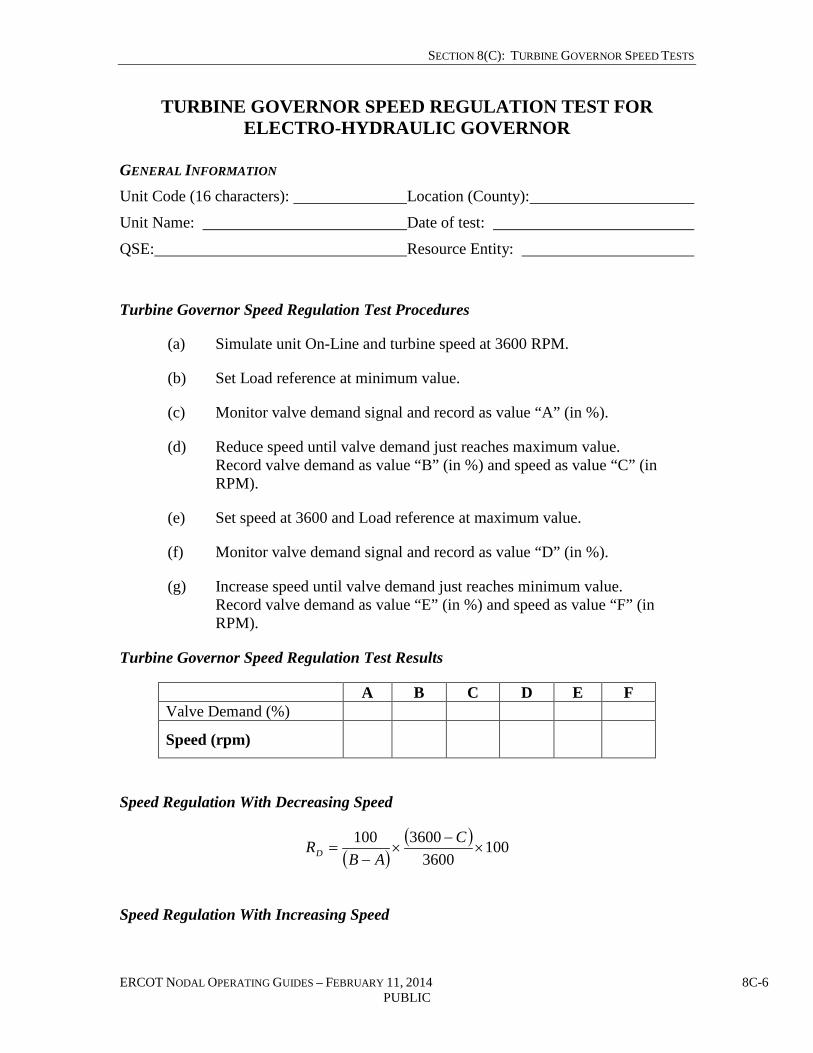
SECTION 8(C): TURBINE GOVERNOR SPEED TESTS
ERCOT NODAL OPERATING GUIDES – FEBRUARY 11, 2014 8C-6 PUBLIC
TURBINE GOVERNOR SPEED REGULATION TEST FOR ELECTRO-HYDRAULIC GOVERNOR
GENERAL INFORMATION Unit Code (16 characters): Location (County):
Unit Name: Date of test:
QSE: Resource Entity:
Turbine Governor Speed Regulation Test Procedures
(a) Simulate unit On-Line and turbine speed at 3600 RPM.
(b) Set Load reference at minimum value.
(c) Monitor valve demand signal and record as value “A” (in %).
(d) Reduce speed until valve demand just reaches maximum value. Record valve demand as value “B” (in %) and speed as value “C” (in RPM).
(e) Set speed at 3600 and Load reference at maximum value.
(f) Monitor valve demand signal and record as value “D” (in %).
(g) Increase speed until valve demand just reaches minimum value. Record valve demand as value “E” (in %) and speed as value “F” (in RPM).
Turbine Governor Speed Regulation Test Results
A B C D E F Valve Demand (%)
Speed (rpm)
Speed Regulation With Decreasing Speed
( )( ) 100
36003600100
×−
×−
=C
ABRD
Speed Regulation With Increasing Speed

SECTION 8(C): TURBINE GOVERNOR SPEED TESTS
ERCOT NODAL OPERATING GUIDES – FEBRUARY 11, 2014 8C-7 PUBLIC
( )( ) 100
36003600100
×−
×−
=F
EDRI
Comments:
SUBMITTAL Resource Entity Representative:
QSE Representative:
Date submitted to ERCOT Representative:

SECTION 8(C): TURBINE GOVERNOR SPEED TESTS
ERCOT NODAL OPERATING GUIDES – FEBRUARY 11, 2014 8C-8 PUBLIC
DEFINITIONS System Frequency Response
This response is a function of two key variables: the Primary Frequency Response from Governors and Load dampening of the connected Load.
Percent Droop Settings
Also known as Frequency Regulation, Speed Regulation, Speed Sensitivity, Speed Error and others. Percent droop is the percent change in nominal frequency that will cause generator output to change from no Load to full Load. It is the change in steady state rotor speed, expressed in percent of rated speed, when power output is gradually reduced from rated to zero power. A common percent droop setting is 5% for both high and low frequency excursions.
Dead-Band The range of deviations of system frequency (+/-) that produces no turbine Governor response, and therefore, no frequency (speed) regulation. It is expressed in percent of rated speed, Hz, or RPM.
Valve Position Limiter
A device that acts on the speed and Load governing system to prevent the Governor-controlled valves from opening beyond a pre-set limit.
Blocked Governor Operation
Operating the generating unit with the control system adjusted to prevent the turbine governor from responding to system frequency (speed) variations. In an effort to reduce speed Governor operation in some generating units, turbine control systems can be adjusted to block the operation of the Governor after the unit is in parallel with the system and is running at its desired output. Selection of a high percent droop characteristic or a large Governor Dead-Band constitutes a form of blocked Governor action.
Variable Pressure Operation
Varying the boiler pressure to improve turbine efficiency at lower Loads. Two methods are normally used. The first method, the turbine control (G.E.) or Governor (Westinghouse) valves are positioned in the wide-open position and the generator is changed by changing the boiler pressure. With this method, there is very little, if any response to frequency excursions. The second method, the valves are positioned at approximately 50% open. The valves are still able to respond to system disturbances. Normal changes in generation requirements are made by varying the boiler pressure until the unit is at rated pressure. After full pressure is reached, the turbine valves are used to make the required generation changes.

SECTION 8(C): TURBINE GOVERNOR SPEED TESTS
ERCOT NODAL OPERATING GUIDES – FEBRUARY 11, 2014 8C-9 PUBLIC
GENERATION RESOURCE FREQUENCY RESPONSE TEST PROCEDURE
DESCRIPTION OF THE TEST 1. The frequency response function of the Generation Resource is tested On-Line at
a Load level that allows the Generation Resource to increase or decrease Load without reaching low operating limits or high operating limits. If the Generation Resource cannot be tested On-Line then it will notify ERCOT that it will be conducting an Off-Line test. The recommended level is 92% Base Load or below.
2. The test is performed by adding a frequency offset signal that exceeds the Governor Dead-Band value to the measured frequency signal. This should create immediate step change in the measured frequency signal.
3. The test starts at time t0 when the frequency Dead-Band is exceeded and signal “Generation Resource Frequency Response On” becomes active.
4. The following signals should be recorded at least two seconds: Unit MW Output, “Generation Resource Frequency Response On.”
5. The duration of the test is 100 seconds. After 100 seconds, the offset signal should be removed and the Generation Resource should return to pretest power output.
6. The test should be conducted both with positive and negative frequency offsets.
7. The test is considered successful after the signal becomes active if at least 70% of the calculated MW contribution is delivered within 16 seconds and the response is maintained for an additional 30 seconds.
8. Droop shall be set not to exceed 5% with a maximum frequency Dead-Band of +/- 0.036Hz.
DEFINITIONS Generation Resource Base Load = maximum Load capability for the season when frequency response test is performed
Gain MW for 0.1Hz = 10*)60*( BandadGovernorDeDroop
P−−
Where:
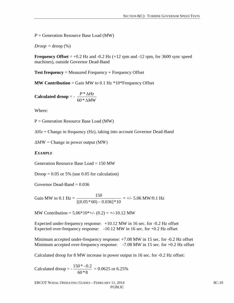
SECTION 8(C): TURBINE GOVERNOR SPEED TESTS
ERCOT NODAL OPERATING GUIDES – FEBRUARY 11, 2014 8C-10 PUBLIC
P = Generation Resource Base Load (MW) Droop = droop (%) Frequency Offset = +0.2 Hz and -0.2 Hz (+12 rpm and -12 rpm, for 3600 sync speed machines), outside Governor Dead-Band Test frequency = Measured Frequency + Frequency Offset MW Contribution = Gain MW to 0.1 Hz *10*Frequency Offset
Calculated droop = - MWHzP
∆∆
*60*
Where: P = Generation Resource Base Load (MW) ΔHz = Change in frequency (Hz), taking into account Governor Dead-Band ΔMW = Change in power output (MW) EXAMPLE Generation Resource Base Load = 150 MW Droop = 0.05 or 5% (use 0.05 for calculation) Governor Dead-Band = 0.036
Gain MW to 0.1 Hz = 10*]036.0)60*05.0[(
150−
= +/- 5.06 MW/0.1 Hz
MW Contribution = 5.06*10*+/- (0.2) = +/-10.12 MW Expected under-frequency response: +10.12 MW in 16 sec. for -0.2 Hz offset Expected over-frequency response: -10.12 MW in 16 sec. for +0.2 Hz offset Minimum accepted under-frequency response: +7.08 MW in 15 sec. for -0.2 Hz offset Minimum accepted over-frequency response: -7.08 MW in 15 sec. for +0.2 Hz offset Calculated droop for 8 MW increase in power output in 16 sec. for -0.2 Hz offset:
Calculated droop = -8*60
2.0*150 − = 0.0625 or 6.25%

SECTION 8(C): TURBINE GOVERNOR SPEED TESTS
ERCOT NODAL OPERATING GUIDES – FEBRUARY 11, 2014 8C-11 PUBLIC
GENERATION RESOURCE FREQUENCY RESPONSE TEST FORM
GENERAL INFORMATION Unit Code (16 characters): Location (County):
Unit Name: Date of Test:
QSE: Resource Entity:
TEST RESULTS
Test with +0.2 Hz Test with -0.2 Hz
1 Generation Resource Base Load
2 GAIN MW to 0.1Hz
3 Calculated MW Contribution
4 MW at test start (t0)
5 MW at t0 + 16 sec
6 MW Contribution at t0 + 16 sec
7 MW at t0 + 46 sec
8 Calculated droop 9 CONCLUSION
(PASSED/FAILED)
Comments:
________________________________________________________________________
________________________________________________________________________
________________________________________________________________________
SUBMITTAL Resource Entity Representative: ____________________________________________
QSE Representative: ______________________________________________________
Date submitted to ERCOT Representative: __________________________ ______

SECTION 8(C): TURBINE GOVERNOR SPEED TESTS
ERCOT NODAL OPERATING GUIDES – FEBRUARY 11, 2014 8C-12 PUBLIC
GENERATION RESOURCE AND CONTROLLABLE LOAD RESOURCE PRIMARY FREQUENCY RESPONSE TEST
PROCEDURES BASED ON HISTORICAL DATA
DESCRIPTION OF HISTORICAL VERIFICATION The purpose of this template is to allow the Entity that operates a Generation Resource or a Controllable Load Resource to demonstrate acceptable frequency response of its Generation Resource(s) or Controllable Load Resource(s) based on historical data in order to minimize testing costs, scheduling conflicts and the risk of damage to equipment or Forced Outage. 1. All verifications will be based on at least one of the Performance, Disturbance,
Compliance Working Group’s (PDCWG’s) list of Measurable Events as defined in the Protocols. Different turbines can be tested using different events.
2. For clarification purposes, the A, B, B+30 and C points are defined in Protocol Section 8.5.2, Primary Frequency Response Measurements. Point A will be considered the start of the verification process. The exact time of each Point is identified in the PDCWG Disturbance Report on the event.
3. The following signals should be recorded at EMS scan rate: Unit MW Output and ERCOT Actual Frequency from the PDCWG Disturbance Report on the event.
4. The verification is considered successful if 70% of the calculated MW contribution is delivered at B point and maintained for an additional 30 seconds.
5. Droop should be set not to exceed 5% and a maximum frequency Dead-Band of +/- 0.036Hz.
6. On request, ERCOT Operations will supply frequency data and time of each evaluation point (A, C, B & B+30) for the event data chosen for the test.
7. Intermittent Renewable Resources (IRRs) located behind one point of interconnection, metered by one ERCOT-Polled Settlement (EPS) Meter, and operated as an integrated Facility may combine IRRs for the purposes of this test.
DEFINITIONS Generation Resource or Controllable Load Resource Base Load = maximum rated capability (this value is not reduced for temporary output limitations of the Generation Resource or Controllable Load Resource due to auxiliary equipment outages, weather conditions, or fuel limitations, it is the “nameplate” rating of the Generation Resource or Controllable Load Resource). For the IRR, the Base Load for purposes of this test shall be the Real-Time telemetered High Sustained Limit (HSL) (MW) of the IRR at the time of the Measurable Event. The IRR shall use only a Measurable Event in which the IRR’s HSL is greater than 50% of the IRR’s total design output capability.

SECTION 8(C): TURBINE GOVERNOR SPEED TESTS
ERCOT NODAL OPERATING GUIDES – FEBRUARY 11, 2014 8C-13 PUBLIC
Gain MW for 0.1Hz = 10*)60*( BandadGovernorDeDroop
P−−
Where: P = Generation Resource or Controllable Load Resource Base Load (MW) Droop = droop (%)
Calculated droop = - 30,,
30,,
*60*
+
+
∆
∆
BBC
BBC
MWHzP
Where: P = Generation Resource or Controllable Load Resource Base Load (MW) ΔHz = Change in frequency (Hz) between Point A and Point C, B, B+30, taking into account Governor Dead-Band ΔMW = Change in power output (MW) between Point A and Point C, B, B+30 EXAMPLE Generation Resource Base Load = 150 MW Governor Dead-Band = 0.036 Hz Droop = 0.05 or 5% (use of 0.05 for calculation) Frequency is 0.1 Hz outside of Governor Dead-Band at Point C, B, or B + 30
Gain MW = 10*]036.0)60*05.0[(
150−
= +/-5.06 MW/0.1 Hz
Expected under-frequency ∆MW: +5.06 MW in 15 sec. for -0.1 Hz offset Expected over-frequency ∆MW: -5.06 MW in 15 sec. for +0.1 Hz offset Minimum accepted under-frequency ∆MW: +3.54 MW in 16 sec. for -0.1 Hz offset Minimum accepted over-frequency ∆MW: -3.54 MW in 16 sec. for +0.1 Hz offset Calculated droop for 5 MW increase in power output in 16 sec. for -0.1 Hz offset:
Calculated droop = -5*60
1.0*150 − = 0.05 or 5.00%

SECTION 8(C): TURBINE GOVERNOR SPEED TESTS
ERCOT NODAL OPERATING GUIDES – FEBRUARY 11, 2014 8C-14 PUBLIC
HISTORICAL GENERATION RESOURCE OR CONTROLLALBE LOAD RESOURCE FREQUENCY RESPONSE TEST FORM
GENERAL INFORMATION Unit Code (16 characters): Location (County):
Unit Name: Date of Event:
QSE: Resource Entity:
HISTORICAL RESULTS
EVALUATION POINT TIME FREQUENCY
POINT A
POINT C
POINT B
POINT B+30
1 Generation Resource or Controllable
Load Resource Base Load
2 MW at A Point
3 MW at B Point
4 MW at B + 30 Point
5 MW at C Point
6 Rated MW at B Point
7 Rated MW at B+30 Point
8 Response at B Point (MW)
9 Response at B+30 Point (MW)
10 Per Unit (PU) Response at B point
11 Per Unit (PU) Response at B+30 Point 12 (PASSED/FAILED)
Pass if #10 & #11 ≥ 0.70 , else Fail

SECTION 8(C): TURBINE GOVERNOR SPEED TESTS
ERCOT NODAL OPERATING GUIDES – FEBRUARY 11, 2014 8C-15 PUBLIC
Comments:
________________________________________________________________________
________________________________________________________________________
________________________________________________________________________
SUBMITTAL Resource Entity Representative: _______________________________________
QSE Representative: ________________________________________________
Date submitted to ERCOT Representative:

SECTION 8(C): TURBINE GOVERNOR SPEED TESTS
ERCOT NODAL OPERATING GUIDES – FEBRUARY 11, 2014 8C-16 PUBLIC
INTERMITTENT RENEWABLE RESOURCE (IRR) FREQUENCY RESPONSE TEST PROCEDURE
DESCRIPTION OF THE TEST 1. The frequency response function of the Intermittent Renewable Resource (IRR) is
tested On-Line at a Load level that allows the IRRs to increase or decrease Load without reaching low operating limits or high operating limits.
2. The test is performed by adding a frequency offset signal that exceeds the Governor Dead-Band value to the measured frequency signal. This should create immediate step change in the measured frequency signal.
3. The test starts at time t0 when the frequency Dead-Band is exceeded.
4. The MW output signal should be recorded at least every two seconds.
5. The duration of the test is 100 seconds. After 100 seconds, the offset signal should be removed and the IRR should return to pretest power output.
6. The test should be conducted both with positive and negative frequency offsets.
7. The test is considered successful after the signal becomes active if at least 70% of the calculated MW contribution is delivered within 16 seconds and the response is maintained for an additional 30 seconds.
8. Droop shall be set not to exceed 5% with a maximum frequency Dead-Band of +/- 0.036Hz.
9. IRRs located behind one Point of Interconnection (POI), metered by one ERCOT-Polled Settlement (EPS) Meter, and operated as an integrated Facility may combine IRRs for the purposes of this test.
DEFINITIONS IRR Base Load = IRR telemetered High Sustained Limit (HSL) at the time of the test. The test shall be performed at an output level which is greater than 50% of IRR’s total design output capability. Gain MW for 0.1Hz consistent with a selected droop percentage =
BandadGovernorDeDroopP
−−60*10*
Where: P = IRR telemetered HSL (MW)

SECTION 8(C): TURBINE GOVERNOR SPEED TESTS
ERCOT NODAL OPERATING GUIDES – FEBRUARY 11, 2014 8C-17 PUBLIC
Droop = droop (%) Frequency Offset = +0.2 Hz and -0.2 Hz, outside Governor Dead-Band Test frequency = Measured Frequency + Frequency Offset MW Contribution = Gain MW to 0.1 Hz * 10 * Frequency Offset
Calculated droop = - MWHzP
∆∆
*60*
Where: P = IRR telemetered HSL (MW) ΔHz = Change in frequency (Hz), taking into account Governor Dead-Band ΔMW = Change in power output (MW) EXAMPLE IRR telemetered HSL = 150 MW Droop = 0.05 or 5% (use 0.05 for calculation) Governor Dead-Band = 0.036 Hz
Gain MW for 0.1 Hz = 10*]036.0)60*05.0[(
150−
= +/- 5.06 MW/0.1 Hz
∆MW Contribution = 5.06 * 10* +/-0.2 = +/-10.12 MW Expected under-frequency response: +10.12 MW in 16 sec. for -0.2 Hz offset Expected over-frequency response: -10.12 MW in 16 sec. for +0.2 Hz offset Minimum accepted under-frequency response: +7.08 MW in 16 sec. for -0.2 Hz offset Minimum accepted over-frequency response: -7.08 MW in 16 sec. for +0.2 Hz offset Calculated droop for 8MW increase in power output in 16 sec. for -0.2 Hz offset:
Calculated percent droop = -8*60
2.0*150 − *100 = 6.25%

SECTION 8(C): TURBINE GOVERNOR SPEED TESTS
ERCOT NODAL OPERATING GUIDES – FEBRUARY 11, 2014 8C-18 PUBLIC
INTERMITTENT RENEWABLE RESOURCE (IRR) FREQUENCY RESPONSE TEST FORM
GENERAL INFORMATION Unit Code (16 characters): Location (County):
Unit Name: Date of Test:
QSE: Resource Entity:
TEST RESULTS
Test with +0.2 Hz Test with -0.2 Hz
1 IRR Base Load
2 GAIN MW to 0.1Hz
3 Calculated Minimum MW Contribution
4 MW at test start (t0)
5 MW at t0 + 16 sec
6 MW Contribution at t0 + 16 sec
7 MW at t0 + 46 sec
8 Calculated droop 9 CONCLUSION
(PASSED/FAILED)
Comments:
________________________________________________________________________
________________________________________________________________________
________________________________________________________________________
SUBMITTAL Resource Entity Representative: _____________________________________________
QSE Representative: ______________________________________________________
Date submitted to ERCOT Control Area Authority Rep.: __________________________

SECTION 8(C): TURBINE GOVERNOR SPEED TESTS
ERCOT NODAL OPERATING GUIDES – FEBRUARY 11, 2014 8C-19 PUBLIC
CONTROLLABLE LOAD RESOURCE FREQUENCY RESPONSE TEST PROCEDURE
DESCRIPTION OF THE TEST 1. The frequency response function of the Controllable Load Resource is tested On-
Line at a Load level that allows Controllable Load Resources to increase or decrease Load without reaching Low Power Consumption (LPC) or Maximum Power Consumption (MPC).
2. The test is performed by adding a frequency offset signal that exceeds the Governor Dead-Band value to the measured frequency signal. This should create an immediate step change in the measured frequency signal.
3. The test starts at time t0 when the frequency Dead-Band is exceeded.
4. The MW output signal should be recorded at least every two seconds.
5. The duration of the test is 100 seconds. After 100 seconds, the offset signal should be removed and the Controllable Load Resource should return to pretest power output.
6. The test should be conducted both with positive and negative frequency offsets.
7. The test is considered successful after the signal becomes active if at least 70% of the calculated MW contribution is delivered within 16 seconds and the response is maintained for an additional 30 seconds.
8. Droop shall be set not to exceed 5% with a maximum frequency Dead-Band of +/- 0.036Hz.
DEFINITIONS Controllable Load Resource Base Load = Controllable Load Resource telemetered MPC at the time of the test. The test shall be performed at an output level that allows the Controllable Load Resource to increase or decrease Load without reaching LPC or MPC. Gain MW for 0.1Hz consistent with a selected droop percentage =
10*)60*( BandadGovernorDeDroopP
−−
Where: P = Controllable Load Resource telemetered MPC (MW) Droop = droop (%)

SECTION 8(C): TURBINE GOVERNOR SPEED TESTS
ERCOT NODAL OPERATING GUIDES – FEBRUARY 11, 2014 8C-20 PUBLIC
Frequency Offset = +0.2 Hz and -0.2 Hz, outside Governor Dead-Band Test frequency = Measured Frequency + Frequency Offset MW Contribution = Gain MW to 0.1 Hz * 10 * Frequency Offset
Calculated droop = - MWHzP
∆∆
*60*
Where: P = Controllable Load Resource telemetered MPC ΔHz = Change in frequency (Hz), taking into account Governor Dead-Band ΔMW = Change in power output (MW) EXAMPLE Controllable Load Resource telemetered MPC = 150 MW Droop = 5% Governor Dead-Band = 0.036 Hz
Gain MW to 0.1 Hz = 10*]036.0)60*05.0[(
150−
= +/- 5.06 MW/0.1 Hz
∆MW Contribution = 5 * 10* +/-0.2 = +/-10.12 MW Expected under-frequency response: -10.12 MW in 16 sec. for -0.2 Hz offset Expected over-frequency response: +10.12 MW in 16 sec. for +0.2 Hz offset Minimum accepted under-frequency response: -7.08 MW in 16 sec. for -0.2 Hz offset Minimum accepted over-frequency response: +7.08 MW in 16 sec. for +0.2 Hz offset Note: The negative sign in expected under-frequency response and minimum accepted under-frequency response denotes the required reduction in power consumption. Similarly the positive sign in expected over-frequency response and minimum accepted over-frequency response denotes the required increase in power consumption. Calculated droop for 8 MW increase in power output in 16 sec. for -0.2 Hz offset:
Calculated percent droop = -8*60
2.0*150 − = 6.25%

SECTION 8(C): TURBINE GOVERNOR SPEED TESTS
ERCOT NODAL OPERATING GUIDES – FEBRUARY 11, 2014 8C-21 PUBLIC
CONTROLLABLE LOAD RESOURCE FREQUENCY RESPONSE TEST FORM
GENERAL INFORMATION Unit Code (16 characters): Location (County):
Unit Name: Date of Test:
QSE: Resource Entity:
TEST RESULTS
Test with +0.2 Hz Test with -0.2 Hz
1 Controllable Load Resource Base Load
2 GAIN MW to 0.1 Hz
3 Calculated Minimum MW Contribution
4 MW at test start (t0)
5 MW at t0 + 16 sec
6 MW Contribution at t0 + 16 sec
7 MW at t0 + 46 sec
8 Calculated droop 9 CONCLUSION
(PASSED/FAILED)
Comments:
________________________________________________________________________
________________________________________________________________________
________________________________________________________________________
SUBMITTAL Resource Entity Representative: _____________________________________________
QSE Representative: ______________________________________________________
Date submitted to ERCOT Control Area Authority Rep.:__________________________

PUBLIC
ERCOT Operating Guides Section 8
Attachment D
Seasonal Unit Net Real Power Capability Verification
December 1, 2010

SECTION 8(D): SEASONAL UNIT NET REAL POWER CAPABILITY VERIFICATION
ERCOT NODAL OPERATING GUIDES – DECEMBER 1, 2010 8D-1 PUBLIC
SEASONAL UNIT NET REAL POWER CAPABILITY VERIFICATION
GENERAL INFORMATION Unit Code (16 character): Location (County):
Unit Name: Date of test:
Generator’s QSE: Resource Entity:
TEST RESULTS Start Time:
Start MW (Gross)*:
Start MW (Net)**:
MW 10 Minutes after Start Time (Gross)*:
MW 10 Minutes after Start Time (Net)**:
Time to Reach Maximum Generation:
Temperature at Plant (°F):
MW at Maximum Generation (Gross)*:
MW at Maximum Generation (Net)**:
MWH Net during the First Full Clock Hour after Maximum Generation is reached:
Limiting Factors:
* Value measured at generator terminals ** Value measured at the point of interconnection SUBMITTAL Resource Entity Representative:
QSE Representative:
Date submitted to ERCOT Rep.:

PUBLIC
ERCOT Nodal Operating Guides Section 8
Attachment E
Black Start Plan Template
October 4, 2013

SECTION 8(E): BLACK START PLAN TEMPLATE
ERCOT NODAL OPERATING GUIDES – OCTOBER 4, 2013 8E-1 PUBLIC
This attachment provides a template to be used by each Transmission Operator (TO) for the development of their Black Start plans. As required by paragraph (2)(a) of Section 4.6.4, Responsibilities, all TOs are required to submit their Black Start plan to ERCOT.
BLACK START PLAN TEMPLATE
I. PURPOSE – The purpose statement will address the intended outcome of the TOs Black Start plan.
II. SCOPE – The scope statement shall provide, in a brief summary, the boundaries of the Black Start plan and to whom the Black Start plan applies.
III. DEFINITIONS – Definitions of terms that are used in the TO Black Start plan that are not common to the ERCOT Region.
IV. KEY PERSONNEL ROLES AND RESPONSIBILITIES – Identify roles and responsibilities of key personnel in case of a Partial Blackout or Blackout.
A. System Operations – Personnel responsible for coordinating in emergency and system restoration.
B. Generation Resources – Personnel responsible for the operation of Black Start Resource(s).
C. Resource Control (Qualified Scheduling Entities (QSEs)) – Personnel responsible for acting as the QSE for Generation Resources.
V. CONTACT INFORMATION – (Identify key personnel and contact information)
A. ERCOT
B. ERCOT contracted Black Start Resources
C. Non-contracted Generation Resources – include Available Generation Resources, Next Start Resources and Co-Generation/Private Use Networks, as applicable.
D. Interconnecting TOs
E. Resource Control (QSEs) System Operations
F. Internal contacts (i.e., chief system operator, directors, managers)
VI. STRATEGIES – Strategies for restoration that are coordinated with ERCOT’s high level strategy for restoring the ERCOT System.

SECTION 8(E): BLACK START PLAN TEMPLATE
ERCOT NODAL OPERATING GUIDES – OCTOBER 4, 2013 8E-2 PUBLIC
A. Cranking Paths – Primary and, if applicable, secondary Cranking Paths from a Black Start Resource to the designated next start Resource.
B. Primary Synchronization Corridors – Primary Synchronization Corridor to the synchronization point(s).
C. Secondary Synchronization Corridors – Secondary Synchronization Corridor to the synchronization point(s).
D. Synchronization procedures – Operating processes to reestablish connections within the TO’s system for areas that have been restored and are prepared for reconnection and procedures for restoring interconnections with other TOs under the direction of ERCOT including location, ownership, and special requirements of each synchronization point.
E. Operating processes for transferring authority back to ERCOT in accordance with ERCOT’s criteria.
VII. PRIORITIES
A. Identifying the Partial Blackout or Blackout event – Clearly state how a Partial Blackout or Blackout event will be recognized.
B. Transferring control away from ERCOT – Acknowledge that, in the event of a partial Blackout or Blackout, the TO will have ERCOT’s authority to bring Generation Resources On-Line and serve Load. The TO should note that it may not be possible for ERCOT to communicate this transfer of authority and that the transfer can be assumed once a Partial Blackout or Blackout condition has been identified.
C. Verification of condition of Black Start Resources – Communications in place to contact Black Start Resources.
D. Maintain acceptable operating voltage and frequency limits during restoration – List acceptable operating voltage and frequency limits during restoration.
E. Verification of tie line status – List of tie lines and owners.
F. Procedures for off-site power requirements of nuclear power plants, including priority of restoration.
G. Provide off-site power to additional Generation Resources.
H. Provide service to key facilities – List key facilities identified by the TO such as essential public services, fuel sources, and military facilities.

SECTION 8(E): BLACK START PLAN TEMPLATE
ERCOT NODAL OPERATING GUIDES – OCTOBER 4, 2013 8E-3 PUBLIC
I. Building stable Island(s) – Primarily focus on building stable Islands with the ultimate goal of reaching synchronization points. TO Black Start plans should also consider that while larger Islands are more stable, they might be more difficult to synchronize with neighboring Islands. The TO’s Black Start plan should contain instructions for adding Load and Generation Resources within the Island.
J. Reaching synchronization points – Focus on restoring the ERCOT System and not restoring service to Customers. The primary focus of the TO Black Start plan should be on building a stable Island that reaches a designated synchronization point.
K. Synchronizing Islands – TOs shall contact ERCOT when Islands are ready to be synchronized. Actual synchronization will occur with TOs communicating directly with each other. ERCOT will coordinate frequency control.
L. Restoring Load after synchronization – Note that after synchronization occurs between Islands, ERCOT will direct the further addition of Load and Generation Resources. The TO will continue to add Load and Generation Resources at the direction of ERCOT as specified in Section VI, Strategies, of this plan.
VIII. OPERATIONS – The TO Black Start plan should address at least the following items and include a subsection for operations of each Island.
A. Generation:
i. System Status Verification – The process a Black Start Resource operator would use to determine status of the transmission system.
ii. ERCOT contracted Black Start Resources:
1. Name/Location
2. Characteristics including, but not limited to the following: MW and MVAr capacity, and type of unit.
3. Fuel source and alternate fuel source
4. Fuel switching
5. Startup characteristics
6. Load Pick-up procedures
iii. Non-contracted Generation Resources

SECTION 8(E): BLACK START PLAN TEMPLATE
ERCOT NODAL OPERATING GUIDES – OCTOBER 4, 2013 8E-4 PUBLIC
1. Available Generation Resources
a. Name/location
b. Characteristics
c. Restoration of station service
d. Fuel source(s)
e. Fuel switching
f. Startup characteristics
g. Load pick-up procedures
2. Next Start Resources
a. Name/location
b. Characteristics
c. Fuel source(s)
d. Fuel switching
e. Startup characteristics
f. Load pick-up procedures
3. Co-generation / Private Use Networks
a. Name/location
b. Characteristics
c. Restoration of station service
d. Fuel source(s)
e. Fuel switching
f. Startup characteristics
g. Load pick-up procedures
B. Transmission

SECTION 8(E): BLACK START PLAN TEMPLATE
ERCOT NODAL OPERATING GUIDES – OCTOBER 4, 2013 8E-5 PUBLIC
i. System Status Verification – The process a TO would use to determine system status.
1. Verification of condition of Black Start Resources
2. Verification of tie line status
ii. Black Start Corridors
1. Switching Guidelines – Operating processes to restore Loads required to restore the ERCOT System, such as station service for substations, Resources to be restarted or stabilized, the Load needed to stabilize generation and frequency, and provide voltage control.
a. Cranking Paths – Switching guidelines for Cranking Paths from a Black Start Resource to the designated next start Resource including a one-line diagram.
b. Primary Synchronization Corridors – Switching guidelines for primary Synchronization Corridor include a one-line diagram.
c. Secondary Synchronization Corridors – Switching guidelines for secondary Synchronization Corridor including a one-line diagram.
iii. Breakers with Synchronization Capability
1. Location and ownership of each synchronization point.
2. Synchronization procedures and special requirements for each location.
iv. Transmission Line Considerations – Special considerations given for system equipment that falls outside the normal mode of operation.
v. Relay Action Considerations
vi. Load Restoration
1. Priorities (key Loads)
2. Loads requiring system voltage and frequency consideration
C. Local Control Center

SECTION 8(E): BLACK START PLAN TEMPLATE
ERCOT NODAL OPERATING GUIDES – OCTOBER 4, 2013 8E-6 PUBLIC
i. Telecommunications system
1. Overview
2. Failure of critical communications
ii. Power Supply
1. Overview
2. Failure of power supply
D. Contingency Plan
i. Failure of contracted Black Start Resources to start
ii. Loss of primary and secondary Synchronization Corridors
1. Coordinate with ERCOT
2. Coordinate with neighboring local control center
3. Identify alternative synchronization points
4. Use the best available transmission corridors

PUBLIC
ERCOT Nodal Operating Guides Section 8
Attachment F
Seasonal Hydro Responsive Reserve Net Capability Verification
December 1, 2010

SECTION 8(F): SEASONAL HYDRO RESPONSIVE RESERVE NET CAPABILITY VERIFICATION
ERCOT NODAL OPERATING GUIDES – DECEMBER 1, 2010 8F-1 PUBLIC
Seasonal Hydro Responsive Reserve Net Capability Verification GENERAL INFORMATION Unit Code (16 character): Location (County):
Unit Name: Date of test:
Generator’s QSE: Resource Entity:
TEST DETAILS Start Time Start MW MW at 20 seconds Max MW SUBMITTAL Resource Entity Representative:
QSE Representative:
Date submitted to ERCOT Rep.:

PUBLIC
ERCOT Nodal Operating Guides Section 8
Attachment G
Load Resource Tests
December 1, 2010

SECTION 8(G): LOAD RESOURCE TESTS
ERCOT NODAL OPERATING GUIDES – DECEMBER 1, 2010 8G-1 PUBLIC
Annual Load Resource Telemetry Test
GENERAL INFORMATION
Date: Location (County):
ERCOT Asset Code: Load Resource’s QSE:
Load Resource Name: Load Point Name: (multiple points only)
FOR TEST DETAILS REFERENCE SECTION 3.4, LOAD RESOURCE TESTING REQUIREMENT. TELEMETRY TEST RESULTS
Start Time Interval:
Load Resource Breaker Status: Response MW:
UFR Status*: MW at Maximum Load**:
Note: * Only applicable to Load Resource’s providing Responsive Reserve Service ** Maximum available capacity for each Load Resources will be capped to the
Maximum Load test level
By signature below, the Load Resource Representative certifies that the telemetry and high set under frequency relays, where applicable, are in place and fully functional.
SUBMITTAL Load Resource Representative Name:
Signature:
QSE Representative: Date submitted to ERCOT:
ERCOT Validation By: Date:

SECTION 8(G): LOAD RESOURCE TESTS
ERCOT NODAL OPERATING GUIDES – DECEMBER 1, 2010 8G-2 PUBLIC
Biennial Test for Load Resource’s Providing Responsive Reserve Service
GENERAL INFORMATION
Date: Location (County):
ERCOT Asset Code: Load Resource’s QSE:
Load Resource Name: Load Point Name: (multiple points only)
INSTRUCTIONS As specified in Protocol Section 8.1.1.2, General Capacity Testing Requirements, a Load Resource providing Responsive Reserve Service shall test each under frequency relay or solid state controller, whichever applies, for correct operation. A separate certified relay test results sheet is to be attached for each relay tested. Please provide sufficient notation on each test sheet to assist ERCOT in matching up the sheet to individual relays. This test of the under frequency relay does not require the Load to be interrupted. If, within the biennial testing period, the Load’s performance has been verified through the correct response to an actual event, the data from that event can be supplied to meet this requirement and the required annual telemetry test. The date, interval, and other information associated with the event are to be noted below. ERCOT will return a copy of the validated test form to the QSE.
VERIFICATION OF TELEMTERED RESPONSE TO AN ACTUAL EVENT
Date of event: Interval of event:
Load Resource Breaker Status: MW Load Prior to Event:
UFR Status: Instantaneous Response MW: Frequency deviation Hz:
Time Load restored: ERCOT Operator:
SUBMITTAL By signature below the Load Resource representative certifies the high set under frequency relay(s) are in place and fully functional.
Load Resource Representative Name:
Signature:
Name of Company Performing Relay Test:
QSE Representative: Date submitted to ERCOT:
ERCOT Validation By: Date:
Note: Please attach certified relay test results sheet(s) to this form when submitting to ERCOT.

PUBLIC
ERCOT Nodal Operating Guides Section 8
Attachment H
Unit Alternative Fuel Capability
December 1, 2010


SECTION 8(H): UNIT ALTERNATIVE FUEL CAPABILITY MARKET PARTICIPANT - PROTECTED INFORMATION
THIS INFORMATION IS PROTECTED INFORMATION PURSUANT TO PROTOCOL SECTION 1.3.1.1(y), ITEMS CONSIDERED PROTECTED INFORMATION AND CONTAINS CONFIDENTIAL/PROPRIETARY INFORMATION OF THE MARKET PARTICIPANT.
THIS INFORMATION MUST BE KEPT STRICTLY CONFIDENTIAL AND IS PROVIDED TO ERCOT EMPLOYEES ONLY ON A"NEED TO KNOW" BASIS AND WILL NOT BE SHARED WITH ANYONE OUTSIDE ERCOT.
ERCOT NODAL OPERATING GUIDES – DECEMBER 1, 2010 8G-1 PUBLIC
General Information
Unit Code Primary Fuel1 Alternative
Fuel1
Alt Source - Pipeline,
Truck, etc…
Date of Last MW
Curtailmenton Primary
Fuel MW
Curtailed Reason for Curtailment/Comments
1Indicate one of the following Fuel Types: BITUMINOUS COAL BUTANE COAL PROCESSES COKE-EVEN COAL DIESEL JET FUEL LANDFILL GAS LIGNITE METHANOL NATURAL GAS NO 1 FUEL OIL NO 2 FUEL OIL NO 4 FUEL OIL NO 5 FUEL OIL NO 6 FUEL OIL NUCLEAR PETROLEUM COKE PROPANE PURCHASED STEAM WATER-CONVENTIONAL PURCHASED STEAM WATER-PUMPED STORAGE REFINERY GAS SUB-BITUMINOUS COAL WIND

SECTION 8(H): UNIT ALTERNATIVE FUEL CAPABILITY MARKET PARTICIPANT - PROTECTED INFORMATION
THIS INFORMATION IS PROTECTED INFORMATION PURSUANT TO PROTOCOL SECTION 1.3.1.1(x), ITEMS CONSIDERED PROTECTED INFORMATION AND CONTAINS CONFIDENTIAL/PROPRIETARY INFORMATION OF THE MARKET PARTICIPANT.
THIS INFORMATION MUST BE KEPT STRICTLY CONFIDENTIAL AND IS PROVIDED TO ERCOT EMPLOYEES ONLY ON A"NEED TO KNOW" BASIS AND WILL NOT BE SHARED WITH ANYONE OUTSIDE ERCOT.
ERCOT NODAL OPERATING GUIDES – DECEMBER 1, 2010 8G-2 PUBLIC
Alternative Fuel
Unit Code
Capable of using 100%
Alternative Fuel –
(Yes/No)
Maximum % Alternative
Blend
No. Hours to Transition to Alternative
Fuel
No. Hours @ HSL using
Alternative Fuel Comments

SECTION 8(H): UNIT ALTERNATIVE FUEL CAPABILITY MARKET PARTICIPANT - PROTECTED INFORMATION
THIS INFORMATION IS PROTECTED INFORMATION PURSUANT TO PROTOCOL SECTION 1.3.1.1(x), ITEMS CONSIDERED PROTECTED INFORMATION AND CONTAINS CONFIDENTIAL/PROPRIETARY INFORMATION OF THE MARKET PARTICIPANT.
THIS INFORMATION MUST BE KEPT STRICTLY CONFIDENTIAL AND IS PROVIDED TO ERCOT EMPLOYEES ONLY ON A"NEED TO KNOW" BASIS AND WILL NOT BE SHARED WITH ANYONE OUTSIDE ERCOT.
ERCOT NODAL OPERATING GUIDES – DECEMBER 1, 2010 8G-3 PUBLIC
Natural Gas Fuel Column 1 Column 2 Column 3 Column 4 Column 5 Column 6 Col 7 Col 8 Column 9
Unit Code
Planned Average MWh/day
(firm+ nonfirm gas)
Average MWh/day firm gas
only
Maximum MW
instantaneous firm +
non-firm gas
Maximum MW
instantaneous firm gas
only
Date Range - (e.g. Nov. 07 -
14)
Delivery (Excluding
Force Majeure) Comments
Firm% Non
Firm%
Note: See example on the following page. In column 2 enter the sum of MWh projected to run over the day, divided by 24 In column 3, enter the sum of MWh projected to run over the day supported by FIRM GAS only, divided by 24 In column 4, enter the maximum MW projected to run instantaneously In column 5, enter the maximum MW projected to run instantaneously that can be supported by FIRM gas and firm delivery In column 6, enter the date range this data covers. If it changes, provide multiple date range entries for each unique occurrence. In column 7, enter the column 3 entry divided by the column 2 entry. In column 8, enter the column 2 entry, minus the column 3 entry, divided by the column 2 entry (2-3)/2

SECTION 8(H): UNIT ALTERNATIVE FUEL CAPABILITY MARKET PARTICIPANT - PROTECTED INFORMATION
THIS INFORMATION IS PROTECTED INFORMATION PURSUANT TO PROTOCOL SECTION 1.3.1.1(x), ITEMS CONSIDERED PROTECTED INFORMATION AND CONTAINS CONFIDENTIAL/PROPRIETARY INFORMATION OF THE MARKET PARTICIPANT.
THIS INFORMATION MUST BE KEPT STRICTLY CONFIDENTIAL AND IS PROVIDED TO ERCOT EMPLOYEES ONLY ON A"NEED TO KNOW" BASIS AND WILL NOT BE SHARED WITH ANYONE OUTSIDE ERCOT.
ERCOT NODAL OPERATING GUIDES – DECEMBER 1, 2010 8G-4 PUBLIC
Natural Gas Fuel Column 1 Column 2 Column 3 Column 4 Column 5 Column 6 Col 7 Col 8 Column 9
Unit Code
Planned Average MWh/day
(firm+ nonfirm gas)
Average MWh/day firm gas
only
Maximum MW
instantaneous firm +
non-firm gas
Maximum MW
instantaneous firm gas
only
Date Range - (e.g. Nov. 07 -
14)
Delivery (Excluding
Force Majeure) Comments
Firm% Non
Firm% Unit A 2 0 100 0 December 7-9 0% 100% Unit B 290 0 600 0 December 7-9 100% Unit C 0 0 0 0 December 7-9 0 0 Available but not planned on Unit D 79 40 650 100 December 7-9 51% 49% Unit E December 7-9 Forced off until December 15 Unit F 33 33 190 0 December 7-9 100% 0% Unit G 0 0 0 0 December 7-9
Note: The form is filled out with examples to help clarify. In column 2 enter the sum of MWh projected to run over the day, divided by 24 In column 3, enter the sum of MWh projected to run over the day supported by FIRM GAS only, divided by 24 In column 4, enter the maximum MW projected to run instantaneously In column 5, enter the maximum MW projected to run instantaneously that can be supported by FIRM gas and firm delivery In column 6, enter the date range this data covers. If it changes, provide multiple date range entries for each unique occurrence. In column 7, enter the column 3 entry divided by the column 2 entry. In column 8, enter the column 2 entry, minus the column 3 entry, divided by the column 2 entry (2-3)/2

PUBLIC
ERCOT Nodal Operating Guides Section 8
Attachment I
Black Start Resource Availability Test Form
October 1, 2012

SECTION 8(I): BLACK START RESOURCE AVAILABILITY TEST FORM
ERCOT NODAL OPERATING GUIDES – OCTOBER 1, 2012 8I-1 PUBLIC
BLACK START RESOURCE AVAILABILITY TEST FORM
As required by Protocol Section 8.1.1.2.1.5, System Black Start Capability and Testing, Black Start Resources shall complete and provide this form to ERCOT on a quarterly basis.
Name of Black Start Resource: _____________________________________________________
Check method to satisfy quarterly Black Start Resource Availability Test:
Black Start Test – Complete Part A
Successful Start and Normal Operation – Complete Part B
PART A – Black Start Test
Date of Test: __________________________
Time ERCOT Notified the Qualified Scheduling Entity (QSE) of testing: ___________________
Actual Start Time: ________________________
Time Black Start Resource reached the Low Sustained Limit (LSL): ______________________
Black Start Resource LSL per the Current Operating Plan (COP): _________________________
Did the Black Start Resource operate at or above its LSL for at least four consecutive Settlement Intervals? ________
Time and Date test was completed (breaker open): _____________________________________
PART B – Successful Start and Normal Operation
Date of Successful Start: _______________________________________
Time Black Start Resource reached the LSL: ________________________________________________
Black Start Resource LSL per the current COP: ___________________________
Did the Black Start Resource operate at or above its LSL for at least four consecutive Settlement Intervals? ________
Was this run time due to an Energy Emergency Alert (EEA) or Normal Operation? ___________
REQUIRED SIGNATURES
QSE Representative Name / Signature: _____________________ / ________________________
Date ___________________________

SECTION 8(I): BLACK START RESOURCE AVAILABILITY TEST FORM
ERCOT NODAL OPERATING GUIDES – OCTOBER 1, 2012 8I-2 PUBLIC
If a Black Start Availability Test was performed:
ERCOT Operator Name / Signature: ________________________ / _______________________
Date ___________________________

PUBLIC
ERCOT Nodal Operating Guides
Section 9: Monitoring Programs
September 25, 2015

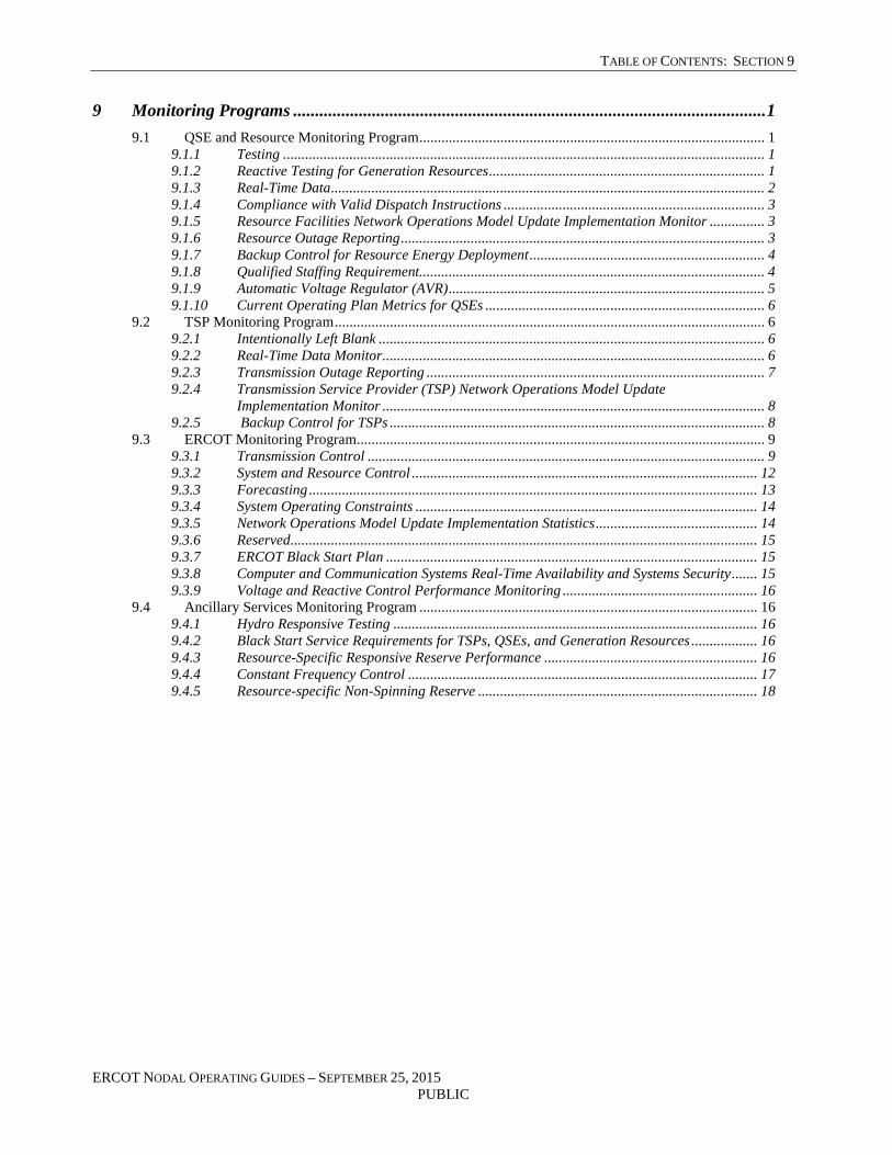
TABLE OF CONTENTS: SECTION 9
ERCOT NODAL OPERATING GUIDES – SEPTEMBER 25, 2015 PUBLIC
9 Monitoring Programs ............................................................................................................ 1
9.1 QSE and Resource Monitoring Program .............................................................................................. 1 9.1.1 Testing ................................................................................................................................... 1 9.1.2 Reactive Testing for Generation Resources ........................................................................... 1 9.1.3 Real-Time Data ...................................................................................................................... 2 9.1.4 Compliance with Valid Dispatch Instructions ....................................................................... 3 9.1.5 Resource Facilities Network Operations Model Update Implementation Monitor ............... 3 9.1.6 Resource Outage Reporting ................................................................................................... 3 9.1.7 Backup Control for Resource Energy Deployment ................................................................ 4 9.1.8 Qualified Staffing Requirement.............................................................................................. 4 9.1.9 Automatic Voltage Regulator (AVR) ...................................................................................... 5 9.1.10 Current Operating Plan Metrics for QSEs ............................................................................ 6
9.2 TSP Monitoring Program ..................................................................................................................... 6 9.2.1 Intentionally Left Blank ......................................................................................................... 6 9.2.2 Real-Time Data Monitor ........................................................................................................ 6 9.2.3 Transmission Outage Reporting ............................................................................................ 7 9.2.4 Transmission Service Provider (TSP) Network Operations Model Update
Implementation Monitor ........................................................................................................ 8 9.2.5 Backup Control for TSPs ...................................................................................................... 8
9.3 ERCOT Monitoring Program ............................................................................................................... 9 9.3.1 Transmission Control ............................................................................................................ 9 9.3.2 System and Resource Control .............................................................................................. 12 9.3.3 Forecasting .......................................................................................................................... 13 9.3.4 System Operating Constraints ............................................................................................. 14 9.3.5 Network Operations Model Update Implementation Statistics ............................................ 14 9.3.6 Reserved ............................................................................................................................... 15 9.3.7 ERCOT Black Start Plan ..................................................................................................... 15 9.3.8 Computer and Communication Systems Real-Time Availability and Systems Security ....... 15 9.3.9 Voltage and Reactive Control Performance Monitoring ..................................................... 16
9.4 Ancillary Services Monitoring Program ............................................................................................ 16 9.4.1 Hydro Responsive Testing ................................................................................................... 16 9.4.2 Black Start Service Requirements for TSPs, QSEs, and Generation Resources .................. 16 9.4.3 Resource-Specific Responsive Reserve Performance .......................................................... 16 9.4.4 Constant Frequency Control ............................................................................................... 17 9.4.5 Resource-specific Non-Spinning Reserve ............................................................................ 18


SECTION 9: MONITORING PROGRAMS
ERCOT NODAL OPERATING GUIDES – SEPTEMBER 25, 2015 9-1 PUBLIC
9 MONITORING PROGRAMS
9.1 QSE and Resource Monitoring Program
This Section sets forth formats and data needed for reporting to comply with Protocol Section 8, Performance Monitoring. These performance monitoring and compliance requirements apply as set forth below to Qualified Scheduling Entities (QSEs), Resources, Transmission Service Providers (TSPs) and ERCOT. Reports defined in this Section will be posted on the Market Information System (MIS) Secure Area unless otherwise stated.
9.1.1 Testing
[Placeholder]
[NOGRR025: Replace or insert applicable paragraph(s) of Section 9.1.1, Testing, above, with the following upon system implementation:]
9.1.1 Testing
ERCOT shall produce reports annually which summarize:
(1) Capability test results for the applicable Resources. These results must be provided to ERCOT by the QSE for the Resource. The QSE shall provide these results to ERCOT upon completion of capability testing of the Resource.
(2) Test results of Emergency Response Service (ERS) Resources by Resource and QSE; and
(3) Test results for Load Resources.
9.1.2 Reactive Testing for Generation Resources
[Placeholder]
[NOGRR025: Replace or insert applicable paragraph(s) of Section 9.1.2, Reactive Testing for Generation Resources, above, with the following upon system implementation:]
9.1.2 Reactive Testing for Generation Resources
(1) The QSE shall provide the following information:
(a) Unit name;
(b) QSE;

SECTION 9: MONITORING PROGRAMS
ERCOT NODAL OPERATING GUIDES – SEPTEMBER 25, 2015 9-2 PUBLIC
(c) Date;
(d) Time;
(e) Tested generation real power capability;
(f) Reported time; and
(g) Corrected Unit Reactive Limit (CURL) and Unit Reactive Limit (URL).
(2) ERCOT shall produce reports annually which describe when the last lagging reactive capability test took place, what the MW and Mega Volt-Ampere Reactive (MVAr) outputs were during the test period, how long the output was held, and a minimum of four MW/MVAr pairs describing the CURL of the unit and any limiting conditions that created the need for a CURL. This data shall be provided by the QSE to ERCOT when reactive testing indicates a change in unit reactive capability and at a minimum of once every two years.
9.1.3 Real-Time Data
ERCOT shall produce reports describing Real-Time data performance of QSEs in the following areas. ERCOT shall post the summary report on the MIS Secure Area.
(a) Telemetry performance:
(i) ERCOT shall produce quarterly reports describing telemetry performance as defined in the Protocols and the Telemetry Standards.
[NOGRR025: Replace or insert applicable paragraph(s) of Section 9.1.3, Real-Time Data, above, upon system implementation:]
9.1.3 Real-Time Data
ERCOT shall produce reports describing Real-Time data performance of QSEs in the following areas. ERCOT shall post the summary report on the MIS Secure Area. Individual point performance shall be posted to the MIS Certified Area.
(a) Telemetry performance:
(i) ERCOT shall produce quarterly reports describing telemetry performance as defined in the Protocols and the Telemetry Standards.
(b) Communication system performance:
(i) ERCOT shall produce monthly reports describing the reliability of each participants Inter-Control Center Communications Protocol (ICCP) data

SECTION 9: MONITORING PROGRAMS
ERCOT NODAL OPERATING GUIDES – SEPTEMBER 25, 2015 9-3 PUBLIC
link to ERCOT as defined in the Protocols and the Telemetry Standards.
(ii) ERCOT shall produce monthly reports describing ICCP link up/down statistics.
9.1.4 Compliance with Valid Dispatch Instructions
(1) ERCOT shall produce monthly reports detailing Resource-specific Regulation Service and energy deployment performance, including Load Resources, based on the criteria described in Protocol Section 8.1.1.4.1, Regulation Service and Generation Resource/Controllable Load Resource Energy Deployment Performance.
(2) ERCOT shall produce a report for any system-wide deployment of Load Resources and/or ERS, on an event basis, within 90 days after the event occurs and shall post it to the MIS Secure Area.
9.1.5 Resource Facilities Network Operations Model Update Implementation Monitor
[Placeholder]
[NOGRR025: Replace or insert applicable paragraph(s) of Section 9.1.5, Resource Facilities Network Operations Model Update Implementation Monitor, above with the following upon system implementation:]
9.1.5 Resource Facilities Network Operations Model Update Implementation Monitor
(1) ERCOT shall prepare monthly reports summarizing the Network Operations Model updates by Resource Facilities. These reports shall include the number of Notices of interim updates submitted to the Public Utility Commission of Texas (PUCT) and the Independent Market Monitor (IMM) as accumulated by QSE due to the actions or inactions of the associated QSE for Network Operations Model Change Requests (NOMCRs) not meeting the timeline pursuant to Protocol Section 3.10.1, Time Line for Network Operations Model Change Requests. These reports shall be delineated by category and owner including reasons for the interim updates. Interim updates caused by ERCOT (i.e. server unavailability, Network Model Management System (NMMS) component failure, site failover, loss of data, staff overload, weather, etc.) shall be reported and attributed to ERCOT.
(2) ERCOT shall post reports on the MIS Secure Area.
9.1.6 Resource Outage Reporting
This Section describes the reporting of data for Resource Outage scheduling by individual Resource for informational purposes. There are no performance metrics for this data.

SECTION 9: MONITORING PROGRAMS
ERCOT NODAL OPERATING GUIDES – SEPTEMBER 25, 2015 9-4 PUBLIC
(1) ERCOT shall post to the MIS Certified Area, a confidential report of total number of Outages reported including Monthly Resource Outage reporting by Resource:
(a) Number of Outage requests submitted in the ERCOT Outage Scheduler greater than 335 days (11 months) in advance;
(b) Number of Outage requests submitted in the ERCOT Outage Scheduler between 90 and 334 days in advance of the desired Outage date;
(c) Number of Outage requests submitted in the ERCOT Outage Scheduler between 45 and 89 days in advance of the desired Outage date;
(d) Number of Outage requests submitted in the ERCOT Outage Scheduler between three and 44 days in advance of the desired Outage date;
(e) Number of Outage requests submitted less than three days in advance;
(f) Number of Outages by Outage type; and
(g) Total number of Outages that were requested, accepted, approved, cancelled, and withdrawn.
9.1.7 Backup Control for Resource Energy Deployment
[Placeholder]
[NOGRR025: Replace Section 9.1.7, Backup Control for Resource Energy Deployment, above, with the following upon system implementation:]
9.1.7 Backup Control for Resource Energy Deployment
ERCOT shall produce a report identifying the date of backup control plan testing and the success or failure of that test for ERCOT and QSEs. Backup control plan tests shall be conducted at least annually.
9.1.8 Qualified Staffing Requirement
[Placeholder]
[NOGRR025: Replace Section 9.1.8, Qualified Staffing Requirement, above, with the following upon system implementation:]
9.1.8 Qualified Staffing Requirement
A QSE shall maintain a continuously operating scheduling center staffed with qualified

SECTION 9: MONITORING PROGRAMS
ERCOT NODAL OPERATING GUIDES – SEPTEMBER 25, 2015 9-5 PUBLIC
personnel with the authority to commit and bind the QSE. ERCOT shall report to the Texas Reliability Entity (Texas RE), instances of suspected non-performance.
9.1.9 Automatic Voltage Regulator (AVR)
[Placeholder]
[NOGRR025: Replace or insert applicable paragraph(s) of Section 9.1.9, Automatic Voltage Regulator (AVR), above with the following upon system implementation:]
9.1.9 Automatic Voltage Regulator (AVR)
(1) ERCOT shall record QSE provided Automatic Voltage Regulator (AVR) test reports for Resources which must include:
(a) The minimum and maximum excitation limiters settings and associated time limits;
(b) Volts/hertz settings;
(c) Gain and time constants;
(d) Date tested; and
(e) Voltage regulator control mode;
(2) ERCOT shall produce a monthly report that will identify Resources for which test reports have not been submitted within the last 60 months.
(3) ERCOT shall produce a monthly report listing the Generation Resources that are not meeting AVR availability for periods in which they are required to provide Voltage Support Service (VSS) as described in paragraph (4) of Protocol Section 3.15.3, QSE Responsibilities Related to Voltage Support. The AVR criteria are described in paragraph (2) of Section 2.7.4.1, Maintaining System Voltage.
9.1.10 Current Operating Plan Metrics for QSEs
ERCOT shall report in the Day-Ahead when the reserved capacity of a QSE’s Resources in the Operating Day Current Operating Plan (COP) at 1430 is not sufficient to supply Ancillary Service requirements for the upcoming Operating Day. ERCOT shall provide a monthly summary of the total days failed and total hours analyzed when the Resource’s reserves are insufficient for any hours during an Operating Day pursuant to paragraph (2) of Protocol Section 8.1.2, Current Operating Plan (COP) Performance Requirements, and not excused due to exemptions contained in the Protocols.
[NOGRR025: Replace or insert applicable paragraph(s) of Section 9.1.10, Current Operating
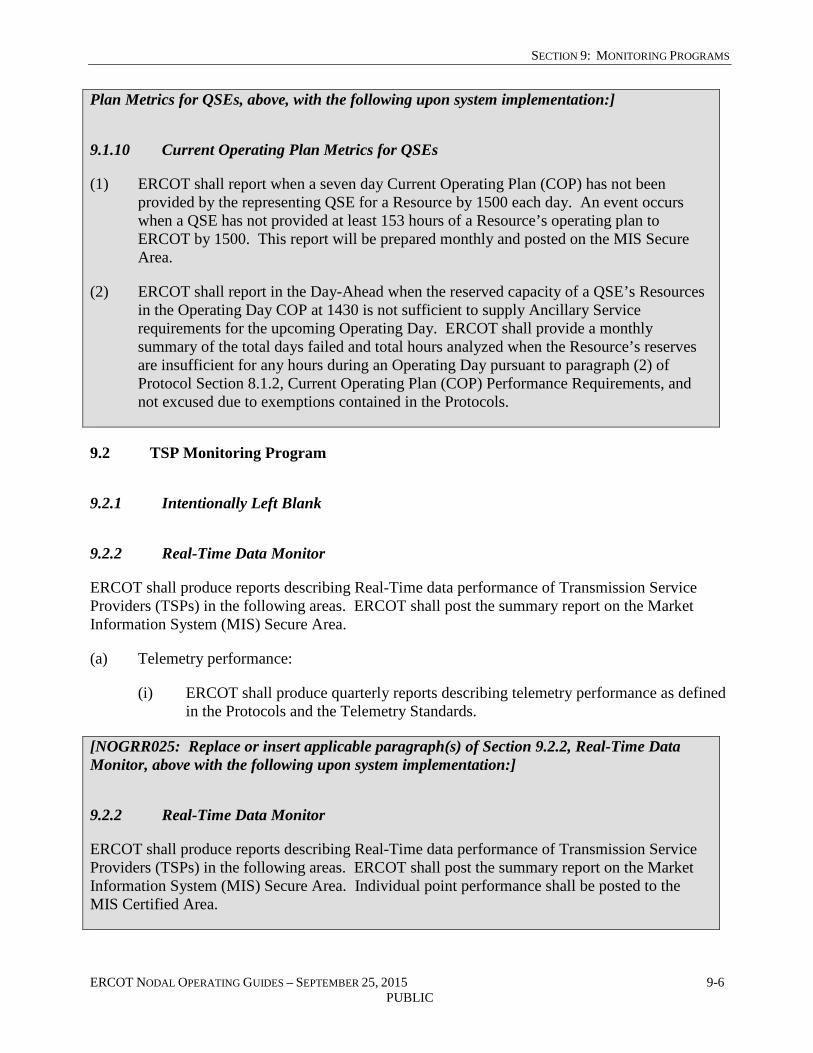
SECTION 9: MONITORING PROGRAMS
ERCOT NODAL OPERATING GUIDES – SEPTEMBER 25, 2015 9-6 PUBLIC
Plan Metrics for QSEs, above, with the following upon system implementation:]
9.1.10 Current Operating Plan Metrics for QSEs
(1) ERCOT shall report when a seven day Current Operating Plan (COP) has not been provided by the representing QSE for a Resource by 1500 each day. An event occurs when a QSE has not provided at least 153 hours of a Resource’s operating plan to ERCOT by 1500. This report will be prepared monthly and posted on the MIS Secure Area.
(2) ERCOT shall report in the Day-Ahead when the reserved capacity of a QSE’s Resources in the Operating Day COP at 1430 is not sufficient to supply Ancillary Service requirements for the upcoming Operating Day. ERCOT shall provide a monthly summary of the total days failed and total hours analyzed when the Resource’s reserves are insufficient for any hours during an Operating Day pursuant to paragraph (2) of Protocol Section 8.1.2, Current Operating Plan (COP) Performance Requirements, and not excused due to exemptions contained in the Protocols.
9.2 TSP Monitoring Program
9.2.1 Intentionally Left Blank
9.2.2 Real-Time Data Monitor
ERCOT shall produce reports describing Real-Time data performance of Transmission Service Providers (TSPs) in the following areas. ERCOT shall post the summary report on the Market Information System (MIS) Secure Area.
(a) Telemetry performance:
(i) ERCOT shall produce quarterly reports describing telemetry performance as defined in the Protocols and the Telemetry Standards.
[NOGRR025: Replace or insert applicable paragraph(s) of Section 9.2.2, Real-Time Data Monitor, above with the following upon system implementation:]
9.2.2 Real-Time Data Monitor
ERCOT shall produce reports describing Real-Time data performance of Transmission Service Providers (TSPs) in the following areas. ERCOT shall post the summary report on the Market Information System (MIS) Secure Area. Individual point performance shall be posted to the MIS Certified Area.

SECTION 9: MONITORING PROGRAMS
ERCOT NODAL OPERATING GUIDES – SEPTEMBER 25, 2015 9-7 PUBLIC
(a) Telemetry performance:
(i) ERCOT shall produce quarterly reports describing telemetry performance as defined in the Protocols and the Telemetry Standards.
(b) Communication system performance:
(i) ERCOT shall produce monthly reports describing the reliability of each participant’s Inter-Control Center Communications Protocol (ICCP) data link to ERCOT as defined in the Protocols and the Telemetry Standards.
(ii) ERCOT shall produce monthly reports describing ICCP link up/down statistics.
9.2.3 Transmission Outage Reporting
[Placeholder]
[NOGRR025 and NOGRR050: Replace or insert applicable paragraph(s) of Section 9.2.3, Transmission Outage Reporting, above, upon system implementation:]
9.2.3 Transmission Outage Reporting
This Section describes the reporting data for the transmission Outage scheduling and is provided for informational purposes. There are no performance metrics for this data.
(1) ERCOT shall post a monthly report of Outages considered on the MIS Secure Area including:
(a) Number of Outage requests submitted in the ERCOT Outage Scheduler greater than 335 days (11 months) in advance;
(b) Number of Outage requests submitted in the ERCOT Outage Scheduler between 90 and 334 days in advance of the desired Outage date;
(c) Number of Outage requests submitted in the ERCOT Outage Scheduler between eight and 89 days in advance of the desired Outage date;
(d) Number of Outage requests submitted in the ERCOT Outage Scheduler between three and seven days in advance of the desired Outage date;
(e) Number of Outage requests submitted less than three days in advance;
(f) Number of Outages by Outage type; and
(g) Total Number of Outages that were requested, accepted, approved, cancelled, and

SECTION 9: MONITORING PROGRAMS
ERCOT NODAL OPERATING GUIDES – SEPTEMBER 25, 2015 9-8 PUBLIC
withdrawn.
(2) ERCOT shall post reports for each transmission owner showing the percentage of the total number of Outages, by type, described in paragraph (1) above.
9.2.4 Transmission Service Provider (TSP) Network Operations Model Update Implementation Monitor
[Placeholder]
[NOGRR025: Replace or insert applicable paragraph(s) of Section 9.2.4, Transmission Service Provider (TSP) Network Operations Model Update Implementation Monitor, above, with the following upon system implementation:]
9.2.4 Transmission Service Provider (TSP) Network Operations Model Update Implementation Monitor
(1) ERCOT shall prepare monthly reports summarizing the Network Operations Model updates by TSPs. The report shall include the number of Notices of interim reports submitted to the Public Utility Commission of Texas (PUCT) and the Independent Market Monitor (IMM) as accumulated by TSP due to the actions or inactions of the associated TSP for Network Operations Model Change Requests (NOMCRs) not meeting the timeline pursuant to Protocol Section 3.10.1, Time Line for Network Operations Model Change Requests. These reports shall be delineated by category and owner including reasons for the interim updates. Interim updates caused by ERCOT (i.e. server unavailability, Network Model Management System (NMMS) component failure, site failover, loss of data, staff overload, weather, etc.) shall be reported and attributed to ERCOT.
(2) ERCOT shall post reports on the MIS Secure Area.
9.2.5 Backup Control for TSPs
[Placeholder]
[NOGRR025: Replace Section 9.2.5, Backup Control for TSPs, above, with the following upon system implementation:]
9.2.5 Backup Control for TSPs
ERCOT shall produce a report identifying the date of backup control plan testing and the success or failure of that test for TSPs. Backup control plan tests shall be conducted at least annually.

SECTION 9: MONITORING PROGRAMS
ERCOT NODAL OPERATING GUIDES – SEPTEMBER 25, 2015 9-9 PUBLIC
9.3 ERCOT Monitoring Program
9.3.1 Transmission Control
ERCOT shall report State Estimator (SE) performance in accordance with the Protocols and the Technical Advisory Committee (TAC)-approved State Estimator Standards and post such report on the Market Information System (MIS) Secure Area.
(a) ERCOT shall produce monthly reports describing SE convergence and valid SE solution rates as described in Protocol Section 3.10.9.2, Telemetry and State Estimator Performance Monitoring.
(b) ERCOT shall produce monthly reports describing the MW differences between SE results and power flow results for identified congested Transmission Elements as approved by TAC.
(c) ERCOT shall produce monthly reports describing the MW differences between the SE results and telemetry for identified congested Transmission Elements as approved by TAC.
(d) ERCOT shall produce monthly reports describing the voltage differences between the SE results and telemetry for the voltage critical buses identified in accordance with the State Estimator Standards.
(e) ERCOT shall produce monthly reports describing the MW differences as defined in the State Estimator Standards.
(f) ERCOT shall produce monthly reports identifying the sum of MW flows around telemetered SE Buses as described in paragraph (5) of Protocol Section 3.10.7.5.2, Continuous Telemetry of the Real-Time Measurements of Bus Load, Voltages, Tap Position, and Flows.
[NOGRR025: Replace or insert applicable paragraph(s) of Section 9.3.1, Transmission Control, above, with the following upon system implementation:]
9.3.1 Transmission Control
(1) ERCOT shall prepare a report describing the operating violations on every transmission line and auto-transformer operated at voltages greater than 60 kV. These reports shall be provided to the Texas Reliability Entity (Texas RE) and the appropriate Technical Advisory Committee (TAC) subcommittee.
(a) ERCOT shall prepare monthly reports on the following:
(i) Exceedance of system operating limits or power transfer limitations set by ERCOT to guard against post-contingency stability exceedance for over

SECTION 9: MONITORING PROGRAMS
ERCOT NODAL OPERATING GUIDES – SEPTEMBER 25, 2015 9-10 PUBLIC
ten minutes;
(ii) N-1 exceedance of the applicable equipment ratings provided by Transmission Service Providers (TSPs), Qualified Scheduling Entities (QSEs), and Resources for over 30 minutes; and
(iii) N-0 exceedance detected during the month, the time duration of the loading above the applicable operating rating and the maximum exceedence level that occurred.
(2) Other transmission monitoring and control metrics:
(a) ERCOT shall prepare reports describing the number of Forced Outages by transmission owner by month.
(b) ERCOT shall post on the Market Information System (MIS) Secure Area its performance in processing Outage requests in accordance with the following table including justification for rolling Outages from one timeline to another:
Amount of time between the request for approval of the proposed Outage and the scheduled start date of the proposed Outage:
ERCOT shall approve or reject no later than:
Three days 1800 hours, two days before the start of the proposed Outage
Between three and eight days 1800 hours, three days before the start of the proposed Outage
Between nine days and 45 days Four days before the start of the proposed Outage
Between 46 and 90 days 40 days before the start of the proposed Outage
Greater than 90 days 75 days before the start of the proposed Outage
(c) ERCOT shall post on the MIS Secure Area, by transmission owner, the number of rejection Notices. The report will include specific concerns that caused the rejection.
(d) ERCOT shall post on the MIS Secure Area, by transmission owner, the number of withdrawals of approved Outages.
(e) ERCOT shall post on the MIS Secure Area, by transmission owner, the number of

SECTION 9: MONITORING PROGRAMS
ERCOT NODAL OPERATING GUIDES – SEPTEMBER 25, 2015 9-11 PUBLIC
approved Outages that were rescheduled by ERCOT.
(3) State Estimator (SE) Performance:
(a) ERCOT shall report SE performance in accordance with the Protocols and the TAC-approved State Estimator Standards and post such report on the MIS Secure Area.
(i) ERCOT shall produce monthly reports describing SE convergence and valid SE solution rates as described in Protocol Section 3.10.9.2, Telemetry and State Estimator Performance Monitoring.
(ii) ERCOT shall produce monthly reports describing the MW differences between SE results and power flow results for identified congested Transmission Elements as approved by TAC.
(iii) ERCOT shall produce monthly reports describing the MW differences between the SE results and telemetry for identified congested Transmission Elements as approved by TAC.
(iv) ERCOT shall produce monthly reports describing the voltage differences between the SE results and telemetry for the voltage critical buses identified in accordance with the State Estimator Standards.
(v) ERCOT shall produce monthly reports describing the MW differences as defined in the State Estimator Standards.
(vi) ERCOT shall produce monthly reports identifying the sum of MW flows around telemetered SE Buses as described in paragraph (5) of Protocol Section 3.10.7.5.2, Continuous Telemetry of the Real-Time Measurements of Bus Load, Voltages, Tap Position, and Flows.
9.3.2 System and Resource Control
The following reports shall be posted on the MIS Secure Area:
(1) Resource control metrics:
(a) Total Regulation Up Service (Reg-Up) and Regulation Down Service (Reg-Down) per interval - ERCOT shall develop a monthly report detailing the total amount of Reg-Up energy deployed in the Settlement Interval and by hour and the total amount of Reg-Down energy deployed for each Settlement Interval and by hour of the Operating Day.
(2) Reliability Unit Commitments (RUCs) and deployments:
SECTION 9: MONITORING PROGRAMS
ERCOT NODAL OPERATING GUIDES – SEPTEMBER 25, 2015 9-12 PUBLIC
(a) For each month, ERCOT shall report, Generation Resources committed in each RUC process, the reason for the commitment, Resource name and intervals deployed, and the hours committed for Voltage Support Service (VSS).
(3) Reversal of Base Point instructions to Generation Resources from interval to interval:
(a) ERCOT shall record and report, on a monthly basis, instances of Dispatch Instructions to Resources not providing Regulation Service in which there is a directional change in Base Point instructions for four consecutive Security-Constrained Economic Dispatch (SCED) intervals for validation and review.
[NOGRR025: Replace or insert applicable paragraph(s) of Section 9.3.2, System and Resource Control, above, with the following upon system implementation:]
9.3.2 System and Resource Control
The following reports shall be posted on the MIS Secure Area:
(1) Resource control metrics:
(a) Total Regulation Up Service (Reg-Up) and Regulation Down Service (Reg-Down) per interval - ERCOT shall develop a monthly report detailing the total amount of Reg-Up energy deployed in the Settlement Interval and by hour and the total amount of Reg-Down energy deployed for each Settlement Interval and by hour of the Operating Day.
(2) Reserve monitoring:
(a) ERCOT shall prepare monthly reports describing the dates and associated duration that ERCOT operated without sufficient operating reserves as defined in the Protocols.
(3) Reliability Unit Commitments (RUCs) and deployments:
(a) For each month, ERCOT shall report, Generation Resources committed in each RUC process, the reason for the commitment, Resource name and intervals deployed, and the hours committed for Voltage Support Service (VSS).
(4) Dynamically Scheduled Resource (DSR) performance and Resource with output schedule:
(a) ERCOT shall produce monthly reports for DSR Load signal failures of more than five minutes.
(b) ERCOT shall produce monthly reports noting the number of Resources on Output Schedule, by QSE.

SECTION 9: MONITORING PROGRAMS
ERCOT NODAL OPERATING GUIDES – SEPTEMBER 25, 2015 9-13 PUBLIC
(5) Reversal of Base Point instructions to Generation Resources from interval to interval:
(a) ERCOT shall record and report, on a monthly basis, instances of Dispatch Instructions to Resources not providing Regulation Service in which there is a directional change in Base Point instructions for four consecutive Security-Constrained Economic Dispatch (SCED) intervals for validation and review.
(6) ERCOT-wide Governor Response to Measurable Events:
(a) ERCOT shall develop monthly reports detailing ERCOT’s System-wide governor response to each Measureable Event. ERCOT shall meet at all times the governor response criteria as described in Protocol Section 8.5.2, Primary Frequency Control Measurements.
9.3.3 Forecasting
[Placeholder]
[NOGRR025: Replace or insert applicable paragraph(s) of Section 9.3.3, Forecasting, above, with the following upon system implementation:]
9.3.3 Forecasting
(1) ERCOT shall report the Mean Absolute Percent Error (MAPE) each month for the following:
(a) The accuracy of each day’s hourly system Load forecast posted at 0600 in the Day-Ahead of the Operating Day as compared with the actual average ERCOT Load for each hour of the Operating Day;
(b) Accuracy of the system hourly Load forecast used for Day-Ahead Reliability Unit Commitment (DRUC) compared to the actual average ERCOT Load for each hour of the Operating Day; and
(c) The accuracy of the hourly Load forecast for the following items compared to the average of the State Estimated Load at each Electrical Bus with a modeled Load for each hour:
(i) Hourly Load forecast used in the DRUC by Weather Zone;
(ii) Hourly Load forecast used in the Hourly Reliability Unit Commitment (HRUC) by Weather Zone; and
(iii) The accuracy of the Load forecast used in the DRUC for the largest MW and Megavolt Ampere (MVA) differences between the hourly Bus Load Forecast and the Real-Time Load at each Electrical Bus, by Weather

SECTION 9: MONITORING PROGRAMS
ERCOT NODAL OPERATING GUIDES – SEPTEMBER 25, 2015 9-14 PUBLIC
Zone.
(2) ERCOT shall prepare monthly reports detailing:
(a) Day-Ahead forecast wind output, by Load Zone, by hour for the Operating Day, used in DRUC and at 0600 at the Day-Ahead.
(b) Actual wind output, aggregated by Load Zone, by hour of the corresponding Operating Day by Load Zone.
9.3.4 System Operating Constraints
[Placeholder]
[NOGRR025: Replace Section 9.3.4, System Operating Constraints, above, with the following upon system implementation:]
9.3.4 System Operating Constraints
ERCOT shall report the following comparisons with respect to Real-Time operations as they occur:
(a) Three consecutive days of a particular congestion constraint (constraints passed to SCED from Network Security Analysis (NSA)) in Real-Time not identified in the Day-Ahead Market (DAM);
(b) Two consecutive hours of a particular congestion constraint in Real-Time not identified in the HRUC process; and
(c) Two consecutive days of a particular congestion constraint in Real-Time not identified in the DRUC process.
9.3.5 Network Operations Model Update Implementation Statistics
[Placeholder]
[NOGRR025: Replace Section 9.3.5, Network Operations Model Update Implementation Statistics, above, with the following upon system implementation:]
9.3.5 Network Operations Model Update Implementation Statistics
ERCOT shall report monthly on the Network Operations Model update implementation statistics. The report shall include the total number of Network Operations Model Change Requests (NOMCRs) submitted, approved, rejected, withdrawn and any other status contained in the

SECTION 9: MONITORING PROGRAMS
ERCOT NODAL OPERATING GUIDES – SEPTEMBER 25, 2015 9-15 PUBLIC
Protocols or defined by ERCOT.
9.3.6 Reserved
9.3.7 ERCOT Black Start Plan
[Placeholder]
[NOGRR025: Replace Section 9.3.7, ERCOT Black Start Plan, above, with the following upon system implementation:]
9.3.7 ERCOT Black Start Plan
ERCOT shall develop an annual Black Start Plan and post it on the MIS Certified Area.
9.3.8 Computer and Communication Systems Real-Time Availability and Systems Security
ERCOT shall report each month the number of times a SCED run was requested but failed to provide a valid result in less time than normal SCED interval.
[NOGRR025: Replace or insert applicable paragraph(s) of Section 9.3.8, Computer and Communication Systems Real-Time Availability and Systems Security, above, with the following upon system implementation:]
9.3.8 Computer and Communication Systems Real-Time Availability and Systems Security
(1) ERCOT shall report each month the availability of its computer and communications systems to the appropriate TAC subcommittee. This report shall include availability statistics for ERCOT’s Inter-Control Center Communications Protocol (ICCP) data links.
(2) ERCOT shall report each month the number of times a SCED run was requested but failed to provide a valid result in less time than normal SCED interval.
(3) ERCOT shall also report each month the number of times the execution of SCED is terminated, by either manual action of the operator or program failure. The number of times of each event will be posted on the MIS Certified Area.

SECTION 9: MONITORING PROGRAMS
ERCOT NODAL OPERATING GUIDES – SEPTEMBER 25, 2015 9-16 PUBLIC
9.3.9 Voltage and Reactive Control Performance Monitoring
ERCOT in coordination with the TSPs shall conduct studies to determine the nominal voltage set points across the ERCOT System for all Electrical Buses used for voltage support and shall post all Voltage Profiles annually on the MIS Secure Area.
[NOGRR025: Replace Section 9.3.9, Voltage and Reactive Control Performance Monitoring, above, with the following upon system implementation:]
9.3.9 Voltage and Reactive Control Performance Monitoring
(1) ERCOT in coordination with the TSPs shall conduct studies to determine the nominal voltage set points across the ERCOT System for all Electrical Buses used for voltage support and shall post all Voltage Profiles annually on the MIS Secure Area.
(2) Transmission owners shall provide switching plans for automatically controlled reactors, capacitors, and other reactive controlled sources to ERCOT. For manually switched reactive devices, the transmission owner shall provide its guidelines for the operation of these devices. These plans and guidelines shall be posted annually to the MIS Secure Area and must be provided in accordance with the NOMCR or other prescribed process.
9.4 Ancillary Services Monitoring Program
ERCOT shall monitor Ancillary Service energy deployment according to the criteria outlined in Protocol Section 8, Performance Monitoring. Reports required by Protocol Section 8.1.1.4, QSE Ancillary Service and Energy Deployment Compliance Criteria, will be posted on the Market Information System (MIS) Certified Area.
9.4.1 Hydro Responsive Testing
ERCOT shall produce quarterly reports of hydro responsive tests and verify results submitted.
9.4.2 Annual Black Start Plan Receipt Confirmation Report
[Placeholder]
[NOGRR025: Replace Section 9.4.2, Annual Black Start Plan Receipt Confirmation Report, above, with the following upon system implementation:]
9.4.2 Annual Black Start Plan Receipt Confirmation Report
ERCOT shall produce annual reports containing record(s) showing if and when a Black Start plan was last received at ERCOT. The report should include the name of Resources participating in Black Start Service (BSS) and the Transmission Operator (TO) name, as well as the date the

SECTION 9: MONITORING PROGRAMS
ERCOT NODAL OPERATING GUIDES – SEPTEMBER 25, 2015 9-17 PUBLIC
Black Start plan was received. TOs shall provide an updated Black Start plan to ERCOT as required by paragraph (2)(a) of Section 4.6.4, Responsibilities, and when the Black Start plan changed.
9.4.3 Resource-Specific Responsive Reserve Performance
(1) ERCOT shall develop monthly reports detailing Resource-specific Responsive Reserve (RRS) performance during deployments, including Load Resources, based on criteria described in Protocol Section 8.1.1.4.2, Responsive Reserve Service Energy Deployment Criteria.
(2) ERCOT shall publish a daily report by 0930 or as soon as practicable on the MIS Public Area for the sudden loss of generation greater than 450MW and shall include:
(a) ERCOT Load at the time of each event;
(b) Time of each event;
(c) Amount of generation and Load lost contributing to the event;
(d) Approximate lowest frequency; and
(e) If there is no loss of generation, the report shall state “No Loss of generation greater than 450MW or greater.”
[NOGRR084: Replace Section 9.4.3, Resource-Specific Responsive Reserve Performance, above, with the following upon system implementation:]
9.4.3 Resource-Specific Responsive Reserve Performance
ERCOT shall develop monthly reports detailing Resource-specific Responsive Reserve (RRS) performance during deployments, including Load Resources, based on criteria described in Protocol Section 8.1.1.4.2, Responsive Reserve Service Energy Deployment Criteria.
9.4.4 Constant Frequency Control
[Placeholder]
[NOGRR025: Replace Section 9.4.4, Constant Frequency Control, above, with the following upon system implementation:]
9.4.4 Constant Frequency Control
ERCOT shall survey Qualified Scheduling Entities (QSEs) qualified to provide Regulation Services to attest that the QSEs have the capability to operate in constant frequency control

SECTION 9: MONITORING PROGRAMS
ERCOT NODAL OPERATING GUIDES – SEPTEMBER 25, 2015 9-18 PUBLIC
mode. ERCOT shall post to the MIS Secure Area annual summaries of QSEs surveyed.
9.4.5 Resource-specific Non-Spinning Reserve
ERCOT shall develop monthly reports detailing Resource-specific Non-Spinning Reserve (Non-Spin) performance during deployments, including Load Resources, based on the criteria described in Protocol Section 8.1.1.4.3, Non-Spinning Reserve Service Energy Deployment Criteria.

PUBLIC
ERCOT Nodal Operating Guides
Section 10: Market Data Transparency
October 7, 2013

TABLE OF CONTENTS: SECTION 10
ERCOT NODAL OPERATING GUIDES – OCTOBER 7, 2013 PUBLIC
10 MARKET DATA TRANSPARENCY ......................................................................................................... 1 10.1 DIRECT CURRENT TIE OUTAGE INFORMATION ..................................................................................................... 1 10.2 DAILY GRID OPERATIONS REPORT ....................................................................................................................... 2

SECTION 10: MARKET DATA TRANSPARENCY
ERCOT NODAL OPERATING GUIDES – OCTOBER 7, 2013 10-1 PUBLIC
10 Market Data Transparency
Information in this section provides reporting transparency for operational level data. The information in this section is provided in addition to those required in the other sections of the Protocols or these Operating Guides. Pursuant to Protocol Section 12.2, ERCOT Responsibilities, ERCOT shall post information to the Market Information System (MIS) as directed throughout these Operating Guides.
10.1 Direct Current Tie Outage Information
(1) In addition to requirements in Protocol Sections 3.1.4.4, Management of Resource or Transmission Forced Outages or Maintenance Outages, and 3.1.5.1, ERCOT Evaluation of Planned Outage and Maintenance Outage of Transmission Facilities, Transmission Service Providers (TSPs) shall also enter the following information into the Outage Scheduler:
(a) Specific work being performed; and
(b) If the Outage is due to work being performed on the Direct Current Tie (DC Tie) or if there is another Outage in the ERCOT Control Area which also requires an Outage on the DC Tie.
(2) As soon as practicable, ERCOT shall post the DC Tie name, start date/time, and end date/time for Forced Outages and Derates on the Market Information System (MIS) Public Area.
(3) One Business Day following the approval or cancellation of a Transmission Facility’s Outage which requires a DC Tie Outage or DC Tie derate, ERCOT shall post the following information on the MIS Public Area:
(a) Equipment name of impacted Transmission Facilities;
(b) Start date and time of impacted Transmission Facilities;
(c) End date and time of impacted Transmission Facilities;
(d) General description of work being performed on impacted Transmission Facilities; and
(e) If the Outage is due to work being performed on the DC Tie or if there is a transmission Outage in the ERCOT Control Area which also requires an Outage on the DC Tie.
(4) One Business Day following the approval or cancellation of a Resource Outage, which requires a DC Tie Outage or DC Tie derate, ERCOT shall post the following information on the MIS Public Area:
(a) Name of impacted DC Tie;
(b) Start date and time of impacted DC Tie;

SECTION 10: MARKET DATA TRANSPARENCY
ERCOT NODAL OPERATING GUIDES – OCTOBER 7, 2013 PUBLIC
(c) End date and time of expected DC Tie Outage or DC Tie; and
(d) Explanation that the DC Tie Outage or DC Tie derate is due to a Resource Outage.
[NOGRR084: Insert Section 10.2, Daily Grid Operations Report, below upon system implementation:]
10.2 Daily Grid Operations Report
For each Operating Day, ERCOT shall post to the MIS Public Area on the following Business Day, a summary level report of the prior day’s operational information that shall include the following data elements:
(a) Peak Load;
(b) Peak hour;
(c) Planned peak Load from the Day Ahead Load Forecast;
(d) Planned peak hour from the Day Ahead Load Forecast;
(e) Amount, duration, time deployed and time recalled for each deployment of Responsive Reserve (RRS) from Generation Resources and Controllable Load Resources;
(f) Each instance of Verbal Dispatch Instruction (VDI) deployment of Load Resources providing RRS;
(g) Amount, duration, time deployed, and time recalled for each Non-Spinning Reserve (Non-Spin) deployment with designation as Off-Line if available;
(h) Security-Constrained Economic Dispatch (SCED) offset (including SCED timestamp, offset timestamp and amount);
(i) Summary of Reliability Unit Commitment (RUC) intervals for which a RUC commitment or decommitment occurred;
(j) Summary of intervals for which Reliability Must-Run (RMR) Resources are committed;
(k) List of SCED intervals which reached the Shadow Price cap and constraint associated with each;
(l) Number of Resources with manual High Dispatch Limits (HDLs) and Low Dispatch Limits (LDLs) manual overrides and a list of the constraints which were the cause of the override;
(m) List of Emergency Condition Notifications; and

SECTION 10: MARKET DATA TRANSPARENCY
ERCOT NODAL OPERATING GUIDES – OCTOBER 7, 2013 PUBLIC
(n) A frequency deviation event equal to or greater than .10 Hz which shall include:
(i) ERCOT Load at the time of each event;
(ii) Time of each event;
(iii) Amount of generation and Load lost contributing to the event; and
(iv) Approximate lowest frequency.

ERCOT NODAL OPERATING GUIDES – APRIL 1, 2014 PUBLIC
ERCOT Nodal Operating Guides
Section 11: Constraint Management Plans and Special Protection Systems
April 1, 2014

TABLE OF CONTENTS: SECTION 11
ERCOT NODAL OPERATING GUIDES – APRIL 1, 2014 PUBLIC
11. CONSTRAINT MANAGEMENT PLANS AND SPECIAL PROTECTION SYSTEMS 11-1
11.1 INTRODUCTION ...........................................................................................................................................11-1 11.2 SPECIAL PROTECTION SYSTEM ....................................................................................................................11-1 11.2.1 Reporting of SPS Operations ............................................................................................................. 11-4 11.3 REMEDIAL ACTION PLAN ............................................................................................................................11-5 11.3.1 Remedial Action Plan Process ........................................................................................................... 11-6 11.4 MITIGATION PLAN ......................................................................................................................................11-6 11.5 PRE-CONTINGENCY ACTION PLANS ............................................................................................................11-7 11.5.1 Pre-Contingency Action Plan Process ............................................................................................... 11-8 11.6 TEMPORARY OUTAGE ACTION PLAN ..........................................................................................................11-8
SECTION 11: CONSTRAINT MANAGEMENT PLANS AND SPECIAL PROTECTION SYSTEMS
ERCOT NODAL OPERATING GUIDES – APRIL 1, 2014 11-1
PUBLIC
11. CONSTRAINT MANAGEMENT PLANS AND SPECIAL PROTECTION SYSTEMS
11.1 Introduction
(1) Constraint Management Plans (CMPs) are a set of pre-defined actions executed in response to system conditions to prevent or resolve one or more thermal or non-thermal transmission security violations or to optimize transmission. CMPs are developed in accordance to the guidelines set forth in the sections below, and are defined in Protocol Section 2.1, Definitions. CMPs include, but are not limited to the following:
(a) Remedial Action Plans (RAPs) which may or may not be modeled in Network Security Analysis (NSA);
(b) Pre-Contingency Action Plans (PCAPs);
(c) Temporary Outage Action Plans (TOAPs); and
(d) Mitigation Plans.
(2) When developing CMPs, ERCOT shall first attempt to utilize the 15-Minute Rating of the impacted Transmission Facilities, where available, to develop RAPs such that the ERCOT Transmission Grid is utilized to the fullest extent.
(3) Special Protection Systems (SPSs) may also be implemented in order to allow Generation Resources or Transmission Facilities that would otherwise be subject to restrictions to operate to their full Rating.
(4) ERCOT shall provide notification to the market of any approved, amended, or removed CMP or SPS. ERCOT shall post to the Market Information System (MIS) Secure Area all CMPs and SPSs.
(5) ERCOT shall provide notification to the market of any proposed SPSs or PCAPs on the MIS Secure Area.
(6) ERCOT is not required to provide notification to the market of any proposed TOAPs.
11.2 Special Protection System
(1) Special Protection Systems (SPSs) are protective relay systems designed to detect abnormal ERCOT System conditions and take pre-planned corrective actions to maintain a secure system.
(2) In addition to the requirements in the Protocols and applicable North American Electric Reliability Corporation (NERC) Reliability Standards, SPSs shall also meet the following requirements:
(a) The SPS owner shall coordinate the design and implementation of the SPS with the owners and operators of Facilities included in the SPS, including but not

SECTION 11: CONSTRAINT MANAGEMENT PLANS AND SPECIAL PROTECTION SYSTEMS
ERCOT NODAL OPERATING GUIDES – APRIL 1, 2014 11-2
PUBLIC
limited to Generation Resources, Transmission Service Providers (TSPs) and Direct Current Ties (DC Ties);
(b) The SPS shall be automatically armed when appropriate;
(c) The SPS shall not operate unnecessarily. To avoid unnecessary SPS operation, the SPS owner may provide a Real-Time status indication to the owner of any Generation Resource controlled by the SPS to show when the flow on one or more of the SPS monitored Facilities exceeds 90% of the flow necessary to arm the SPS. The cost necessary to provide such status indication shall be the responsibility of the SPS owner;
(d) The status indication of any automatic or manual arming/activation or operation of the SPS shall be provided as Supervisory Control and Data Acquisition (SCADA) alarm inputs to the owners of any Facility controlled by the SPS;
(e) When an SPS is removed from service, the SPS owner or its Designated Agent shall immediately notify ERCOT;
(f) When an SPS is returned to service, the SPS owner or its Designated Agent shall immediately notify ERCOT. ERCOT shall modify its reliability constraints to recognize the availability of the SPS;
(g) The SPS owner shall telemeter the status indication of the following items by SCADA to ERCOT for incorporation into ERCOT systems:
(i) Any automatic or manual arming/activation or operation of the SPS;
(ii) The in-service/out-of-service status of the SPS; and
(iii) Any additional related telemetry that already exists pertinent to the monitoring of the SPS (e.g. status indication of communications links between associated SPS equipment and the owner’s control center, arming limits of associated SPS equipment).
(h) The TSP may receive telemetry for a Resource Entity owned SPS through ERCOT or through the SPS owner, at the option of the TSP. The SPS owner, at its own cost, must provide telemetry for Resource Entity owned SPSs to the TSP upon request.
(4) The owners of an existing, modified, or proposed SPS shall submit documentation of the SPS to ERCOT for review and compilation into an ERCOT SPS database. The documentation shall detail the design, operation, functional testing, and coordination of the SPS with other protection and control systems.
(a) ERCOT shall conduct a review of each proposed SPS and each proposed modification to an existing SPS. Additionally, it shall conduct a review of each existing SPS at least every five years as required by changes in system conditions.

SECTION 11: CONSTRAINT MANAGEMENT PLANS AND SPECIAL PROTECTION SYSTEMS
ERCOT NODAL OPERATING GUIDES – APRIL 1, 2014 11-3
PUBLIC
Each review shall proceed according to a process and timetable documented in ERCOT Procedures and shall be posted on the Market Information System (MIS) Secure Area.
(b) The review of a proposed SPS shall be completed before the SPS is placed in service, unless ERCOT specifically determines that exemption of the proposed SPS from the review completion requirement is warranted. The timing of placing the SPS into service must be coordinated with and approved by ERCOT. The implementation schedule must be confirmed through submission of a Network Operations Model Change Request (NOMCR) to ERCOT.
(c) Existing SPSs that have already undergone at least one review shall remain in service during any subsequent review. Modifications to existing SPSs may be implemented upon approval by ERCOT.
(d) The process and schedule for placing an SPS into service must be consistent with documented ERCOT Procedures. The schedule must be coordinated among ERCOT and the owners of the Facility controlled by the SPS, and shall provide sufficient time to perform any necessary testing prior to its being placed in service.
(e) ERCOT review of an SPS shall:
(i) Identify any conflicts with the Protocols, NERC Reliability Standards, and these Operating Guides;
(ii) Evaluate and document the consequences of failure of a single component of the SPS, which would result in failure of the SPS to operate when required; and
(iii) Evaluate and document the consequences of misoperation, incorrect operation, or unintended operation of an SPS, when considered by itself and without any other system contingency.
(iv) Upon completion of ERCOT’s SPS review, ERCOT shall provide all results and underlying studies to the SPS owner.
(f) If deficiencies are identified by ERCOT or other parties’ comments, the SPS owner shall either submit an amended SPS proposal or withdraw the SPS proposal. The amended SPS proposal shall undergo the review process specified in item (e) above until the identified deficiencies have been resolved to the satisfaction of ERCOT.
(g) As part of the ERCOT review, ERCOT shall notify the Steady State Working Group (SSWG), the Dynamics Working Group (DWG), and the System Protection Working Group (SPWG) of the SPS proposal, and each working group or any member of each working group may provide any comments, questions, or

SECTION 11: CONSTRAINT MANAGEMENT PLANS AND SPECIAL PROTECTION SYSTEMS
ERCOT NODAL OPERATING GUIDES – APRIL 1, 2014 11-4
PUBLIC
issues to ERCOT. ERCOT may work with the owner(s) of Facilities controlled by the SPS as necessary to address all issues.
(h) ERCOT shall develop a method to include the SPS in Security-Constrained Economic Dispatch (SCED), Outage coordination, and Reliability Unit Commitment (RUC).
(i) ERCOT’s review shall provide an opportunity for and include consideration of comments submitted by Market Participants affected by the SPS.
11.2.1 Reporting of SPS Operations
(1) SPS owners shall notify ERCOT of all SPS operations. Documentation of SPS failures or misoperations shall be provided to ERCOT using the Relay Misoperation Report form on the ERCOT website. The SPS owner shall conduct an analysis of all SPS operations, misoperations, and failures. If deficiencies are identified, a plan to correct the deficiencies shall be developed by the SPS owner subject to the approval of ERCOT and implemented by the SPS owner. (2) ERCOT shall report all SPS operations and misoperations to the Texas Reliability Entity (Texas RE) for review. SPS arming or activation that ramps generation back is not considered an operation or misoperation with respect to reporting requirements to the Texas RE. An operation and misoperation of an SPS with respect to reporting requirements to the Texas RE occurs when changes to the transmission system occur, including, but not limited to circuit breaker operation. Owners of SPSs will provide a monthly report to ERCOT by the 15th of each month describing each instance an SPS armed/activated and reset during the previous month. The report will include the date and time of arming/activation and reset. ERCOT shall consolidate the monthly reports and forward to the Texas RE.
(3) If an SPS which removes generation from service operates more than two times within a six month period and the operations are not a direct result of an ERCOT System disturbance or a contingency operation, ERCOT may require the Generation Resource owner(s) to decrease the available capability on the affected Generation Resource(s). The amount of available capacity to be decreased shall be determined by ERCOT. The decreased available capacity on the Generation Resource(s) shall remain until the Generation Resource owner(s) provides documentation that demonstrates the Generation Resource(s) can properly control output in a pre-contingency or normal ERCOT System condition.
(4) For each SPS, the owner shall either identify a preferred exit strategy or explain why no exit strategy is needed to ERCOT. This shall take place according to a timetable documented in ERCOT Procedures and posted on the MIS Secure Area. Once an exit strategy is complete and a SPS is no longer needed, the owner of an existing SPS shall notify ERCOT, whenever the SPS is to be permanently disabled, and shall do so according to a timetable coordinated with and approved by ERCOT and the owners of all Facilities controlled by the SPS.

SECTION 11: CONSTRAINT MANAGEMENT PLANS AND SPECIAL PROTECTION SYSTEMS
ERCOT NODAL OPERATING GUIDES – APRIL 1, 2014 11-5
PUBLIC
11.3 Remedial Action Plan
(1) Remedial Action Plans (RAPs) are defined in Protocol Section 2.1, Definitions and may be relied upon in allowing additional use of the transmission system in SCED. Normally, it is desirable that a Transmission Service Provider (TSP) constructs Transmission Facilities adequate to eliminate the need for any RAP; however, in some circumstances, such construction may be unachievable in the available time frame.
(2) RAPs must:
(a) Be coordinated by ERCOT with all Transmission Operators (TOs) and Resource Entities included in the RAP, and approved by ERCOT;
(b) Be llimited to the time required to construct replacement Transmission Facilities; however, the RAP will remain in effect if ERCOT has determined the replacement Transmission Facilities to be impractical;
(c) Comply with all applicable requirements in the Protocols and applicable North American Electric Reliability Corporation (NERC) Reliability Standards;
(d) Clearly define and document TOs and Resource Entities included in the RAP actions;
(e) Must be able to resolve the issue for which it was designed over the range of conditions that might reasonably be experienced;
(f) Be executed by the TOs and/or Resource Entities;
(g) Have a 15-minute Rating greater than the Normal and Emergency Ratings for the Transmission Facilities it intends to resolve;
(h) Be defined in the Network Operations Model and considered in the Security-Constrained Economic Dispatch (SCED) and Reliability Unit Commitment (RUC). RAPs that cannot be modeled using ERCOT’s existing infrastructure shall be rejected unless the Technical Advisory Committee (TAC) approves a plan to work around the infrastructure problem; and
(i) Not include Load shed.
(3) An approved RAP may be executed immediately after a contingency by the TOs and Resource Entities included in the RAP without instruction by ERCOT or shall be executed upon direction by ERCOT.
(4) ERCOT shall conduct a review of each existing RAP annually or as required by changes in system conditions to ensure its continued effectiveness. Each review shall proceed according to a process and timetable documented in ERCOT Procedures.

SECTION 11: CONSTRAINT MANAGEMENT PLANS AND SPECIAL PROTECTION SYSTEMS
ERCOT NODAL OPERATING GUIDES – APRIL 1, 2014 11-6
PUBLIC
(5) ERCOT may approve the expiration of a RAP after consultation with the TOs and Resource Entities included in the RAP. ERCOT shall modify its reliability constraints to recognize the unavailability of the RAP.
11.3.1 Remedial Action Plan Process
RAPs may be proposed by any Market Participant or may be developed by ERCOT. For RAPs submitted by Market Participants not registered as a TSP:
(a) ERCOT shall post RAPs submitted by a Market Participant not registered as a TSP on the Market Information System (MIS) Secure Area as soon as practicable, but no later than five Business Days of receipt.
(b) ERCOT shall provide a five Business Day comment period from the date when the proposed RAP under review is posted by ERCOT unless notice of a shorter comment period is provided.
(c) ERCOT shall consider all comments received within the five Business Day comment period on the proposed RAP, along with its own evaluation and those of the Transmission Facility owners, and either approve, modify or reject that proposed RAP.
(d) If a proposed RAP is modified or rejected, ERCOT shall post an explanation for the rejection or a description of the modification.
11.4 Mitigation Plan
(1) Mitigation Plans are defined in Protocol Section 2.1, Definitions, and shall not be used to manage constraints in Security-Constrained Economic Dispatch (SCED) by either activating them or deactivating them. Normally, it is desirable that a Transmission Service Provider (TSP) constructs Transmission Facilities adequate to eliminate the need for a Mitigation Plan; however, in some circumstances, such construction may be unachievable in the available time frame.
(2) A Mitigation Plan may be proposed by any TSP, but must be approved by ERCOT and the impacted Transmission Operator (TO) prior to implementation. Mitigation Plans must:
(a) Be coordinated with the TOs included in the Mitigation Plan;
(b) Limited in use to the time required to construct replacement Transmission Facilities; however, the Mitigation Plan will remain in effect if ERCOT has determined the replacement Transmission Facilities to be impractical;
(c) Comply with all requirements of the Protocols and applicable North American Electric Reliability Corporation (NERC) Reliability Standards;
(d) Clearly define and document TO actions;

SECTION 11: CONSTRAINT MANAGEMENT PLANS AND SPECIAL PROTECTION SYSTEMS
ERCOT NODAL OPERATING GUIDES – APRIL 1, 2014 11-7
PUBLIC
(e) Be executed by TOs;
(f) Be able to be implemented in a timeframe that will not result in loss of the overloaded Transmission Facility;
(g) Identify the most limiting protective relay setting beyond the 15-Minute Rating when developing the Mitigation Plan in advance or as soon as practicable when developing the Mitigation Plan in Real-Time; and
(h) Not subject ERCOT to unacceptable risk of widespread cascading Outages.
(3) An approved Mitigation Plan may be executed immediately, post-contingency, by the TO without instruction by ERCOT or shall be executed upon direction by ERCOT.
(4) Restoration of any Load shed by executing the Mitigation Plan shall be coordinated with ERCOT.
11.5 Pre-Contingency Action Plans
(1) Pre-Contingency Action Plans (PCAPs) are defined in Protocol Section 2.1, Definitions, and are implemented in anticipation of a contingency. Normally, it is desirable that a Transmission Service Provider (TSP) construct Transmission Facilities adequate to eliminate the need for any PCAP; however, in some circumstances, such construction may be unachievable in the available time frame.
(2) A PCAP may be proposed by any Market Participant, but must be approved by ERCOT and the impacted Transmission Operator (TO) prior to implementation. PCAPs must:
(a) Be coordinated with the TOs included in the PCAP;
(b) Be limited in use to the time required to construct replacement Transmission Facilities and until such Facilities are placed in-service, or the PCAP is no longer needed; however, the PCAP will remain in effect if ERCOT has determined the replacement Transmission Facilities to be impractical;
(c) Comply with all requirements of the Protocols and applicable North American Electric Reliability Corporation (NERC) Reliability Standards;
(d) Clearly define and document TO actions;
(e) Be executed by TOs; and
(f) Not include Load shed.
(3) An approved PCAP may be executed immediately prior to a contingency by the TO without instruction by ERCOT, or shall be executed upon direction by ERCOT.

SECTION 11: CONSTRAINT MANAGEMENT PLANS AND SPECIAL PROTECTION SYSTEMS
ERCOT NODAL OPERATING GUIDES – APRIL 1, 2014 11-8
PUBLIC
(4) All proposed, approved, amended, and removed PCAPs shall be managed in accordance with paragraph (4) of Section 11.1, Introduction.
(5) ERCOT may limit the quantity of PCAPs that are used.
11.5.1 Pre-Contingency Action Plan Process
PCAPs may be proposed by any Market Participant or may be developed by ERCOT. For PCAPs submitted by Market Participants not registered as a TSP:
(a) ERCOT shall post PCAPs submitted by a Market Participant not registered as a TSP on the Market Information System (MIS) Secure Area as soon as practicable, but no later than five Business Days of receipt.
(b) ERCOT shall provide a five Business Day comment period from the date when the proposed PCAP under review is posted by ERCOT unless notice of a shorter comment period is provided.
(c) ERCOT shall consider all comments received within the five Business Day comment period on the proposed PCAP, along with its own evaluation and those of the Transmission Facility owners, and either approve, modify or reject that proposed PCAP.
(d) If a proposed PCAP is modified or rejected, ERCOT shall post an explanation for the rejection or a description of the modification
11.6 Temporary Outage Action Plan
(1) Temporary Outage Action Plans (TOAPs) are defined in Protocol Section 2.1, Definitions, and shall not be used to manage constraints in Security-Constrained Economic Dispatch (SCED) by either activating them or deactivating them.
(2) A TOAP may be proposed by any Market Participant. TOAPs shall be approved by ERCOT prior to implementation. TOAPs must:
(a) Be coordinated with the Transmission Operators (TOs) included in the TOAP;
(b) Limit use to the duration of a specific Transmission Facility or Resource Outage;
(c) Comply with all requirements of the Protocols and applicable North American Electric Reliability Corporation (NERC) Reliability Standards;
(d) Clearly define and document TO actions;
(e) Be executed by TOs;
(f) Be implemented in a timeframe that will not result in loss of the overloaded Transmission Facility;

SECTION 11: CONSTRAINT MANAGEMENT PLANS AND SPECIAL PROTECTION SYSTEMS
ERCOT NODAL OPERATING GUIDES – APRIL 1, 2014 11-9
PUBLIC
(g) Identify the most limiting protective relay setting beyond the 15-Minute Rating when developing the TOAP in advance or as soon as practicable when developing the TOAP in Real-Time; and
(h) Not subject ERCOT to unacceptable risk of widespread cascading Outages.
(3) An approved TOAP may be executed immediately, post-contingency, by the TO without instruction by ERCOT or shall be executed upon direction by ERCOT.
(4) ERCOT may limit the quantity of TOAPs that are used.
(5) Restoration of any Load shed by executing the TOAP shall be coordinated with ERCOT.