Embed Size (px)
Citation preview

ER41 Variable Speed Drives for Asynchronous and Synchronous Motors
EthernetIP Modbus TCP Manual
09/2017
BLEMO Frequenzumrichter
Siemensstraße 4 D-63110 Rodgau – Dudenhofen
Tel.: +49 / 6106 / 82 95-0 Fax: +49 / 6106 / 82 95-20 Internet: www.blemo.com E-Mail: [email protected]

2
The information provided in this documentation contains general descriptions and/or technical character-
istics of the performance of the products contained herein. This documentation is not intended as a
substitute for and is not to be used for determining suitability or reliability of these products for specific user
applications. It is the duty of any such user or integrator to perform the appropriate and complete risk
analysis, evaluation and testing of the products with respect to the relevant specific application or use
thereof. Neither BLEMO nor any of its affiliates or subsidiaries shall be responsible or liable for misuse of
the information contained herein. If you have any suggestions for improvements or amendments or have
found errors in this publication, please notify us.
No part of this document may be reproduced in any form or by any means, electronic or mechanical,
including photocopying, without express written permission of BLEMO.
All pertinent state, regional, and local safety regulations must be observed when installing and using this
product. For reasons of safety and to help ensure compliance with documented system data, only the
manufacturer should perform repairs to components.
When devices are used for applications with technical safety requirements, the relevant instructions must
be followed.
Failure to use BLEMO software or approved software with our hardware products may result in injury,
harm, or improper operating results.
Failure to observe this information can result in injury or equipment damage.
© 2017 BLEMO. All Rights Reserved.

3
Table of Contents
Safety Information. . . . . . . . . . . . . . . . . . . . . . . . . . . . . . . . . . . . . . . . . . . . 7
About the Book . . . . . . . . . . . . . . . . . . . . . . . . . . . . . . . . . . . . . . . . . . . . . . 11 Chapter 1 Presentation . . . . . . . . . . . . . . . . . . . . . . . . . . . . . . . . . . . . . . . . . . . . . . . . 13
Hardware Overview . . . . . . . . . . . . . . . . . . . . . . . . . . . . . . . . . . . . . . . . . . . . . . . . . . . . . . . . 14
Software Overview . . . . . . . . . . . . . . . . . . . . . . . . . . . . . . . . . . . . . . . . . . . . . . . . . . . . . . . . 15 Chapter 2 Basics . . . . . . . . . . . . . . . . . . . . . . . . . . . . . . . . . . . . . . . . . . . . . . . . . . . . . 17
2.1 Introduction . . . . . . . . . . . . . . . . . . . . . . . . . . . . . . . . . . . . . . . . . . . . . . . . . . . . . . . . . . . . . . 18
Introduction . . . . . . . . . . . . . . . . . . . . . . . . . . . . . . . . . . . . . . . . . . . . . . . . . . . . . . . . . . . . . . 19
Network Layer Supported Functions/Protocols . . . . . . . . . . . . . . . . . . . . . . . . . . . . . . . . . . . 20
TCP and UDP Protocol . . . . . . . . . . . . . . . . . . . . . . . . . . . . . . . . . . . . . . . . . . . . . . . . . . . . . 21 2.2 Modbus TCP Features . . . . . . . . . . . . . . . . . . . . . . . . . . . . . . . . . . . . . . . . . . . . . . . . . . . . . 23
Modbus TCP Frames . . . . . . . . . . . . . . . . . . . . . . . . . . . . . . . . . . . . . . . . . . . . . . . . . . . . . . 24
Modbus TCP Servers . . . . . . . . . . . . . . . . . . . . . . . . . . . . . . . . . . . . . . . . . . . . . . . . . . . . . . 25
Supported Modbus TCP Functions . . . . . . . . . . . . . . . . . . . . . . . . . . . . . . . . . . . . . . . . . . . . 26
Application Profile with Modbus TCP . . . . . . . . . . . . . . . . . . . . . . . . . . . . . . . . . . . . . . . . . . 27 2.3 Ethernet IP Features . . . . . . . . . . . . . . . . . . . . . . . . . . . . . . . . . . . . . . . . . . . . . . . . . . . . . . . 28
EtherNet/IP . . . . . . . . . . . . . . . . . . . . . . . . . . . . . . . . . . . . . . . . . . . . . . . . . . . . . . . . . . . . . . 29
Cyclical Exchanges (Implicit Exchanges) . . . . . . . . . . . . . . . . . . . . . . . . . . . . . . . . . . . . . . . 30
Messaging (Explicit Exchanges) . . . . . . . . . . . . . . . . . . . . . . . . . . . . . . . . . . . . . . . . . . . . . . 33
Timeout Monitoring . . . . . . . . . . . . . . . . . . . . . . . . . . . . . . . . . . . . . . . . . . . . . . . . . . . . . . . . 33 2.4 CIP Object . . . . . . . . . . . . . . . . . . . . . . . . . . . . . . . . . . . . . . . . . . . . . . . . . . . . . . . . . . . . . . . 34
Supported Object Classes . . . . . . . . . . . . . . . . . . . . . . . . . . . . . . . . . . . . . . . . . . . . . . . . . . . 35
Identity Object (01 hex) . . . . . . . . . . . . . . . . . . . . . . . . . . . . . . . . . . . . . . . . . . . . . . . . . . . . . 36
Message Router Object (02 hex). . . . . . . . . . . . . . . . . . . . . . . . . . . . . . . . . . . . . . . . . . . . . . 39
TCP/IP Interface Object (F5 hex) . . . . . . . . . . . . . . . . . . . . . . . . . . . . . . . . . . . . . . . . . . . . . 40
Ethernet Link Object (F6 hex) . . . . . . . . . . . . . . . . . . . . . . . . . . . . . . . . . . . . . . . . . . . . . . . . 43
Assembly Object (04 hex) . . . . . . . . . . . . . . . . . . . . . . . . . . . . . . . . . . . . . . . . . . . . . . . . . . . 45
Connection Manager Object (06 hex) . . . . . . . . . . . . . . . . . . . . . . . . . . . . . . . . . . . . . . . . . . 47
Motor Data Object (28 hex) . . . . . . . . . . . . . . . . . . . . . . . . . . . . . . . . . . . . . . . . . . . . . . . . . . 49
Control Supervisor Object (29 hex) . . . . . . . . . . . . . . . . . . . . . . . . . . . . . . . . . . . . . . . . . . . . 50
AC/DC Drive Object (2A hex) . . . . . . . . . . . . . . . . . . . . . . . . . . . . . . . . . . . . . . . . . . . . . . . . 52
Application Object (70 hex to C7 hex) / Explicit Messaging . . . . . . . . . . . . . . . . . . . . . . . . . 55
Base Energy Object (4E hex) . . . . . . . . . . . . . . . . . . . . . . . . . . . . . . . . . . . . . . . . . . . . . . . . 56
Electrical Energy Object (4F hex) . . . . . . . . . . . . . . . . . . . . . . . . . . . . . . . . . . . . . . . . . . . . . 58 Chapter 3 Hardware Setup . . . . . . . . . . . . . . . . . . . . . . . . . . . . . . . . . . . . . . . . . . . . . 61
Hardware Presentation . . . . . . . . . . . . . . . . . . . . . . . . . . . . . . . . . . . . . . . . . . . . . . . . . . . . . 62
Firmware Version . . . . . . . . . . . . . . . . . . . . . . . . . . . . . . . . . . . . . . . . . . . . . . . . . . . . . . . . . 62
Installation of the Module. . . . . . . . . . . . . . . . . . . . . . . . . . . . . . . . . . . . . . . . . . . . . . . . . . . . 63
Electrical Installation . . . . . . . . . . . . . . . . . . . . . . . . . . . . . . . . . . . . . . . . . . . . . . . . . . . . . . . 64
Cable Routing Practice . . . . . . . . . . . . . . . . . . . . . . . . . . . . . . . . . . . . . . . . . . . . . . . . . . . . . 65 Chapter 4 Software Setup . . . . . . . . . . . . . . . . . . . . . . . . . . . . . . . . . . . . . . . . . . . . . . 67
4.1 Basic Settings . . . . . . . . . . . . . . . . . . . . . . . . . . . . . . . . . . . . . . . . . . . . . . . . . . . . . . . . . . . . 68
IP Parameter Settings . . . . . . . . . . . . . . . . . . . . . . . . . . . . . . . . . . . . . . . . . . . . . . . . . . . . . . 69
[Device Name] PAn . . . . . . . . . . . . . . . . . . . . . . . . . . . . . . . . . . . . . . . . . . . . . . . . . . . . . . 70
[ETH Option IP Mode ]IM10 . . . . . . . . . . . . . . . . . . . . . . . . . . . . . . . . . . . . . . . . . . . . . . . 71
[Eth Option IP]IC11IC12IC13IC14 . . . . . . . . . . . . . . . . . . . . . . . . . . . . . . . . . . 71
[Eth Option Subnet Mask]IM11IM12IM13IM14. . . . . . . . . . . . . . . . . . . . . . . . . . . 72
[Eth Option Gate Add]IG11IG12IG13IG14 . . . . . . . . . . . . . . . . . . . . . . . . . . . . 72
[Enable FDR] FdV1 . . . . . . . . . . . . . . . . . . . . . . . . . . . . . . . . . . . . . . . . . . . . . . . . . . . . . . 73
[FDR Action] FdA1 . . . . . . . . . . . . . . . . . . . . . . . . . . . . . . . . . . . . . . . . . . . . . . . . . . . . . . 73
[FDR Operating State] FdS1. . . . . . . . . . . . . . . . . . . . . . . . . . . . . . . . . . . . . . . . . . . . . . . 74
4
[FDR Error Status] Fdr1 . . . . . . . . . . . . . . . . . . . . . . . . . . . . . . . . . . . . . . . . . . . . . . . . . . 74
[MAC @] MACO. . . . . . . . . . . . . . . . . . . . . . . . . . . . . . . . . . . . . . . . . . . . . . . . . . . . . . . . . . 75
[ETH opt Rx frames]ErXO . . . . . . . . . . . . . . . . . . . . . . . . . . . . . . . . . . . . . . . . . . . . . . . . . 75
[ETH opt Tx frames]EtXO . . . . . . . . . . . . . . . . . . . . . . . . . . . . . . . . . . . . . . . . . . . . . . . . . 75
[ETH opt error frames]EErO. . . . . . . . . . . . . . . . . . . . . . . . . . . . . . . . . . . . . . . . . . . . . . . . 75
[Actual rate]Ard . . . . . . . . . . . . . . . . . . . . . . . . . . . . . . . . . . . . . . . . . . . . . . . . . . . . . . . . . 76
[Enable Webserver] EWE . . . . . . . . . . . . . . . . . . . . . . . . . . . . . . . . . . . . . . . . . . . . . . . . . . 76
[Reset OptWeb Passwd]rWP0 . . . . . . . . . . . . . . . . . . . . . . . . . . . . . . . . . . . . . . . . . . . . . . 77
[Com. Module cmd.] CMd3 . . . . . . . . . . . . . . . . . . . . . . . . . . . . . . . . . . . . . . . . . . . . . . . . . 77
[Com. Module Ref Freq] LFr3 . . . . . . . . . . . . . . . . . . . . . . . . . . . . . . . . . . . . . . . . . . . . . . 77
[Ethernet Timeout] ttOb . . . . . . . . . . . . . . . . . . . . . . . . . . . . . . . . . . . . . . . . . . . . . . . . . . 78 4.2 Additional Settings . . . . . . . . . . . . . . . . . . . . . . . . . . . . . . . . . . . . . . . . . . . . . . . . . . . . . . . . . 79
FDR Settings . . . . . . . . . . . . . . . . . . . . . . . . . . . . . . . . . . . . . . . . . . . . . . . . . . . . . . . . . . . . . 80
RSTP Settings . . . . . . . . . . . . . . . . . . . . . . . . . . . . . . . . . . . . . . . . . . . . . . . . . . . . . . . . . . . . 81
Configuring I/O Scanning . . . . . . . . . . . . . . . . . . . . . . . . . . . . . . . . . . . . . . . . . . . . . . . . . . . . 83
DNS Settings . . . . . . . . . . . . . . . . . . . . . . . . . . . . . . . . . . . . . . . . . . . . . . . . . . . . . . . . . . . . . 84
SNTP Settings . . . . . . . . . . . . . . . . . . . . . . . . . . . . . . . . . . . . . . . . . . . . . . . . . . . . . . . . . . . . 85
SNMP Settings. . . . . . . . . . . . . . . . . . . . . . . . . . . . . . . . . . . . . . . . . . . . . . . . . . . . . . . . . . . . 86 4.3 Fast Device Replacement . . . . . . . . . . . . . . . . . . . . . . . . . . . . . . . . . . . . . . . . . . . . . . . . . . . 88
Presentation . . . . . . . . . . . . . . . . . . . . . . . . . . . . . . . . . . . . . . . . . . . . . . . . . . . . . . . . . . . . . . 89
Startup Detailed Behavior . . . . . . . . . . . . . . . . . . . . . . . . . . . . . . . . . . . . . . . . . . . . . . . . . . . 90
FDR Operation Behavior . . . . . . . . . . . . . . . . . . . . . . . . . . . . . . . . . . . . . . . . . . . . . . . . . . . . 91
Local Configuration . . . . . . . . . . . . . . . . . . . . . . . . . . . . . . . . . . . . . . . . . . . . . . . . . . . . . . . . 92
Downloaded Configuration. . . . . . . . . . . . . . . . . . . . . . . . . . . . . . . . . . . . . . . . . . . . . . . . . . . 93 4.4 Communication Profile . . . . . . . . . . . . . . . . . . . . . . . . . . . . . . . . . . . . . . . . . . . . . . . . . . . . . . 95
Definition of a Profile . . . . . . . . . . . . . . . . . . . . . . . . . . . . . . . . . . . . . . . . . . . . . . . . . . . . . . . 96
Functional Profiles Supported by the Drive . . . . . . . . . . . . . . . . . . . . . . . . . . . . . . . . . . . . . . 97
Functional Description . . . . . . . . . . . . . . . . . . . . . . . . . . . . . . . . . . . . . . . . . . . . . . . . . . . . . . 98
CIA402 Operating State Diagram . . . . . . . . . . . . . . . . . . . . . . . . . . . . . . . . . . . . . . . . . . . . . 99
Description of Operating States . . . . . . . . . . . . . . . . . . . . . . . . . . . . . . . . . . . . . . . . . . . . . . . 100
Summary . . . . . . . . . . . . . . . . . . . . . . . . . . . . . . . . . . . . . . . . . . . . . . . . . . . . . . . . . . . . . . . . 102
Cmd Register CMd. . . . . . . . . . . . . . . . . . . . . . . . . . . . . . . . . . . . . . . . . . . . . . . . . . . . . . . . 103
Stop Commands . . . . . . . . . . . . . . . . . . . . . . . . . . . . . . . . . . . . . . . . . . . . . . . . . . . . . . . . . . 104
Assigning Control Word Bits . . . . . . . . . . . . . . . . . . . . . . . . . . . . . . . . . . . . . . . . . . . . . . . . . 104
[CIA402 State Reg] EtA . . . . . . . . . . . . . . . . . . . . . . . . . . . . . . . . . . . . . . . . . . . . . . . . . . . 105
Starting Sequence . . . . . . . . . . . . . . . . . . . . . . . . . . . . . . . . . . . . . . . . . . . . . . . . . . . . . . . . . 106
Sequence for a Drive Powered by the Power Stage Supply . . . . . . . . . . . . . . . . . . . . . . . . . 107
Sequence for a Drive with Separate Control Stage . . . . . . . . . . . . . . . . . . . . . . . . . . . . . . . . 108
Sequence for a Drive with Mains Contactor Control . . . . . . . . . . . . . . . . . . . . . . . . . . . . . . . 111 4.5 Embedded Webserver . . . . . . . . . . . . . . . . . . . . . . . . . . . . . . . . . . . . . . . . . . . . . . . . . . . . . . 112
Overview . . . . . . . . . . . . . . . . . . . . . . . . . . . . . . . . . . . . . . . . . . . . . . . . . . . . . . . . . . . . . . . . 113
Connection to the Webserver. . . . . . . . . . . . . . . . . . . . . . . . . . . . . . . . . . . . . . . . . . . . . . . . . 114
My Dashboard . . . . . . . . . . . . . . . . . . . . . . . . . . . . . . . . . . . . . . . . . . . . . . . . . . . . . . . . . . . . 116
Display - Drive . . . . . . . . . . . . . . . . . . . . . . . . . . . . . . . . . . . . . . . . . . . . . . . . . . . . . . . . . . . . 117
Setup - My Preference . . . . . . . . . . . . . . . . . . . . . . . . . . . . . . . . . . . . . . . . . . . . . . . . . . . . . . 118 4.6 Fieldbus Integration Using Unity Pro (M580) . . . . . . . . . . . . . . . . . . . . . . . . . . . . . . . . . . . . . 119
Introduction . . . . . . . . . . . . . . . . . . . . . . . . . . . . . . . . . . . . . . . . . . . . . . . . . . . . . . . . . . . . . . 120
EtherNet/IP Configuration . . . . . . . . . . . . . . . . . . . . . . . . . . . . . . . . . . . . . . . . . . . . . . . . . . . 120
Configuration of the Master . . . . . . . . . . . . . . . . . . . . . . . . . . . . . . . . . . . . . . . . . . . . . . . . . . 121
DTM Library . . . . . . . . . . . . . . . . . . . . . . . . . . . . . . . . . . . . . . . . . . . . . . . . . . . . . . . . . . . . . . 121
DTM Browser . . . . . . . . . . . . . . . . . . . . . . . . . . . . . . . . . . . . . . . . . . . . . . . . . . . . . . . . . . . . . 122 Chapter 5 Operations . . . . . . . . . . . . . . . . . . . . . . . . . . . . . . . . . . . . . . . . . . . . . . . . . . 123
5.1 Operating States . . . . . . . . . . . . . . . . . . . . . . . . . . . . . . . . . . . . . . . . . . . . . . . . . . . . . . . . . . 124
Configuring Communication Error Response. . . . . . . . . . . . . . . . . . . . . . . . . . . . . . . . . . . . . 124

5
5.2 Operating Modes . . . . . . . . . . . . . . . . . . . . . . . . . . . . . . . . . . . . . . . . . . . . . . . . . . . . . . . . . . 126
Configuring the Control Channel . . . . . . . . . . . . . . . . . . . . . . . . . . . . . . . . . . . . . . . . . . . . . . 127
Configuration of the Drive for Operation in I/O Profile . . . . . . . . . . . . . . . . . . . . . . . . . . . . . . 128
Configuration of the Drive for Operation with CiA 402 Profile in Combined Mode . . . . . . . . 129
Configuration of the Drive for Operation with CiA 402 Profile in Separate Mode . . . . . . . . . 130 Chapter 6 Diagnostic and Troubleshooting . . . . . . . . . . . . . . . . . . . . . . . . . . . . . . . . . 131
Fieldbus Status LEDs . . . . . . . . . . . . . . . . . . . . . . . . . . . . . . . . . . . . . . . . . . . . . . . . . . . . . . 132
Connection for Fieldbus Mode. . . . . . . . . . . . . . . . . . . . . . . . . . . . . . . . . . . . . . . . . . . . . . . . 134
Fieldbus Functions Test . . . . . . . . . . . . . . . . . . . . . . . . . . . . . . . . . . . . . . . . . . . . . . . . . . . . 135
Control-Signal Diagnostics . . . . . . . . . . . . . . . . . . . . . . . . . . . . . . . . . . . . . . . . . . . . . . . . . . 137
Glossary . . . . . . . . . . . . . . . . . . . . . . . . . . . . . . . . . . . . . . . . . . . . . . . . . . . . . 139

6

7
Safety Information
Important Information
NOTICE
PLEASE NOTE
Read these instructions carefully, and look at the equipment to become familiar with the device before
trying to install, operate, service, or maintain it. The following special messages may appear throughout
this documentation or on the equipment to warn of potential hazards or to call attention to information that
clarifies or simplifies a procedure.
Electrical equipment should be installed, operated, serviced, and maintained only by qualified personnel.
No responsibility is assumed by BLEMO for any consequences arising out of the use of this material.
A qualified person is one who has skills and knowledge related to the construction and operation of
electrical equipment and its installation, and has received safety training to recognize and avoid the
hazards involved.
Qualification Of Personnel
Only appropriately trained persons who are familiar with and understand the contents of this manual and
all other pertinent product documentation are authorized to work on and with this product. In addition, these
persons must have received safety training to recognize and avoid hazards involved. These persons must
have sufficient technical training, knowledge and experience and be able to foresee and detect potential
hazards that may be caused by using the product, by changing the settings and by the mechanical,
electrical and electronic equipment of the entire system in which the product is used. All persons working
on and with the product must be fully familiar with all applicable standards, directives, and accident
prevention regulations when performing such work.
8
Intended Use
This product is a drive for three-phase synchronous and asynchronous motors and intended for industrial
use according to this manual.The product may only be used in compliance with all applicable safety
standard and local regulations and directives, the specified requirements and the technical data. The
product must be installed outside the hazardous ATEX zone. Prior to using the product, you must perform
a risk assessment in view of the planned application. Based on the results, the appropriate safety
measures must be implemented.Since the product is used as a component in an entire system, you must
ensure the safety of persons by means of the design of this entire system (for example, machine design).
Any use other than the use explicitly permitted is prohibited and can result in hazards. Electrical equipment
should be installed, operated, serviced, and maintained only by qualified personnel.
Product Related Information
Read and understand these instructions before performing any procedure with this drive.
Drive systems may perform unexpected movements because of incorrect wiring, incorrect settings,
incorrect data or other errors.
Damaged products or accessories may cause electric shock or unanticipated equipment operation.
DANGER HAZARD OF ELECTRIC SHOCK, EXPLOSION OR ARC FLASH
Only appropriately trained persons who are familiar with and understand the contents of this manual
and all other pertinent product documentation and who have received safety training to recognize and
avoid hazards involved are authorized to work on and with this drive system. Installation, adjustment,
repair and maintenance must be performed by qualified personnel.
The system integrator is responsible for compliance with all local and national electrical code
requirements as well as all other applicable regulations with respect to grounding of all equipment.
Many components of the product, including the printed circuit boards, operate with mains voltage. Do
not touch. Use only electrically insulated tools.
Do not touch unshielded components or terminals with voltage present.
Motors can generate voltage when the shaft is rotated. Prior to performing any type of work on the
drive system, block the motor shaft to prevent rotation.
AC voltage can couple voltage to unused conductors in the motor cable. Insulate both ends of unused
conductors of the motor cable.
Do not short across the DC bus terminals or the DC bus capacitors or the braking resistor terminals.
Before performing work on the drive system:
Disconnect all power, including external control power that may be present.
Place a Do Not Turn On label on all power switches.
Lock all power switches in the open position.
Wait 15 minutes to allow the DC bus capacitors to discharge. The DC bus LED is not an indicator
of the absence of DC bus voltage that can exceed 800 Vdc.
Measure the voltage on the DC bus between the DC bus terminals (PA/+, PC/-) using a properly
rated voltmeter to verify that the voltage is < 42 Vdc.
If the DC bus capacitors do not discharge properly, contact your local BLEMO representative. Do
not repair or operate the product.
Install and close all covers before applying voltage.
WARNING UNANTICIPATED EQUIPMENT OPERATION
Carefully install the wiring in accordance with the EMC requirements.
Do not operate the product with unknown or unsuitable settings or data.
Perform a comprehensive commissioning test.

9
Contact your local BLEMO sales office if you detect any damage whatsoever.
(1) For USA: Additional information, refer to NEMA ICS 1.1 (latest edition), Safety Guidelines for the
Application, Installation, and Maintenance of Solid State Control and to NEMA ICS 7.1 (latest edition),
Safety Standards for Construction and Guide for Selection, Installation and Operation of Adjustable-Speed
Drive Systems.
The temperature of the products described in this manual may exceed 80 °C (176 °F) during operation.
This equipment has been designed to operate outside of any hazardous location. Only install this
equipment in zones known to be free of a hazardous atmosphere.
DANGER ELECTRIC SHOCK OR UNANTICIPATED EQUIPMENT OPERATION
Do not use damaged products or accessories.
Failure to follow these instructions will result in death or serious injury.
WARNING LOSS OF CONTROL
The designer of any control scheme must consider the potential failure modes of control paths and,
for critical control functions, provide a means to achieve a safe state during and after a path failure.
Examples of critical control functions are emergency stop, overtravel stop, power outage and restart.
Separate or redundant control paths must be provided for critical control functions.
System control paths may include communication links. Consideration must be given to the
implications of unanticipated transmission delays or failures of the link.
Observe all accident prevention regulations and local safety guidelines (1).
Each implementation of the product must be individually and thoroughly tested for proper operation
before being placed into service.
NOTICE DESTRUCTION DUE TO INCORRECT MAINS VOLTAGE
Before switching on and configuring the product, verify that it is approved for the mains voltage
WARNING HOT SURFACES
Ensure that any contact with hot surfaces is avoided.
Do not allow flammable or heat-sensitive parts in the immediate vicinity of hot surfaces.
Verify that the product has sufficiently cooled down before handling it.
Verify that the heat dissipation is sufficient by performing a test run under maximum load conditions.
DANGER POTENTIAL FOR EXPLOSION
Install and use this equipment in non-hazardous locations only.

10
Machines, controllers, and related equipment are usually integrated into networks. Unauthorized persons
and malware may gain access to the machine as well as to other devices on the network/fieldbus of the
machine and connected networks via insufficiently secure access to software and networks.
WARNING UNAUTHORIZED ACCESS TO THE MACHINE VIA SOFTWARE AND NETWORKS
In your hazard and risk analysis, consider all hazards that result from access to and operation on the
network/fieldbus and develop an appropriate cyber security concept.
Verify that the hardware infrastructure and the software infrastructure into which the machine is
integrated as well as all organizational measures and rules covering access to this infrastructure
consider the results of the hazard and risk analysis and are implemented according to best practices
and standards covering IT security and cyber security (such as: ISO/IEC 27000 series, Common
Criteria for Information Technology Security Evaluation, ISO/ IEC 15408, IEC 62351, ISA/IEC 62443,
NIST Cybersecurity Framework, Information Security Forum - Standard of Good Practice for
Information Security).
Verify the effectiveness of your IT security and cyber security systems using appropriate, proven
methods.

11
About the Book
At a Glance
Document Scope
The purpose of this document is to:
� Show you how to install the Ethernet fieldbus on your drive.
� Show you how to configure drive to use Ethernet for monitoring and control.
� Provide examples of setup using Unity
NOTE: Read and understand this document and all related documents (see below) before
installing,operating, or maintaining your drive.
Validity Note
This documentation is valid for the ER41 drives.
The technical characteristics of the devices described in this document also appear online. To access this
information online:
The characteristics that are presented in this manual should be the same as those characteristics that
appear online. In line with our policy of constant improvement, we may revise content over time to improve
clarity and accuracy. If you see a difference between the manual and online information, use the online
information as your reference.
Step Action
1 Go to the BLEMO home page www.blemo.com.
2 In the Search box type the reference of a product or the name of a product range.
� Do not include blank spaces in the reference or product range.
� To get information on grouping similar modules, use asterisks (*).
3 If you entered a reference, go to the Product Datasheets search results and click on the reference that
interests you.
If you entered the name of a product range, go to the Product Ranges search results and click on the
product range that interests you.
4 If more than one reference appears in the Products search results, click on the reference that interests you.
5 Depending on the size of your screen, you may need to scroll down to see the data sheet.
6 To save or print a data sheet as a .pdf file, click Download XXX product datasheet.

12
Related Documents
Terminology
Use your tablet or your PC to quickly access detailed and comprehensive information on all our products
on www.blemo.com.
The technical terms, terminology, and the corresponding descriptions in this manual normally use the
terms or definitions in the relevant standards.
The technical terms, terminology, and the corresponding descriptions in this manual normally use the
terms or definitions in the relevant standards.
Among others, these standards include:
� IEC 61800 series: Adjustable speed electrical power drive systems
� IEC 61508 Ed.2 series: Functional safety of electrical/electronic/programmable electronic safety-related
� EN 954-1 Safety of machinery - Safety related parts of control systems
� EN ISO 13849-1 & 2 Safety of machinery - Safety related parts of control systems.
� IEC 61158 series: Industrial communication networks - Fieldbus specifications
� IEC 61784 series: Industrial communication networks - Profiles
� IEC 60204-1: Safety of machinery - Electrical equipment of machines – Part 1: General requirements
In addition, the term zone of operation is used in conjunction with the description of specific hazards, and
is defined as it is for a hazard zone or danger zone in the EC Machinery Directive (2006/42/EC) and in ISO
12100-1.
Also see the glossary at the end of this manual.

13
Chapter 1 Presentation
What Is in This Chapter?
This chapter contains the following topics:
Topic Page
Hardware Overview 14
Software Overview 15
14
Presentation
Hardware Overview
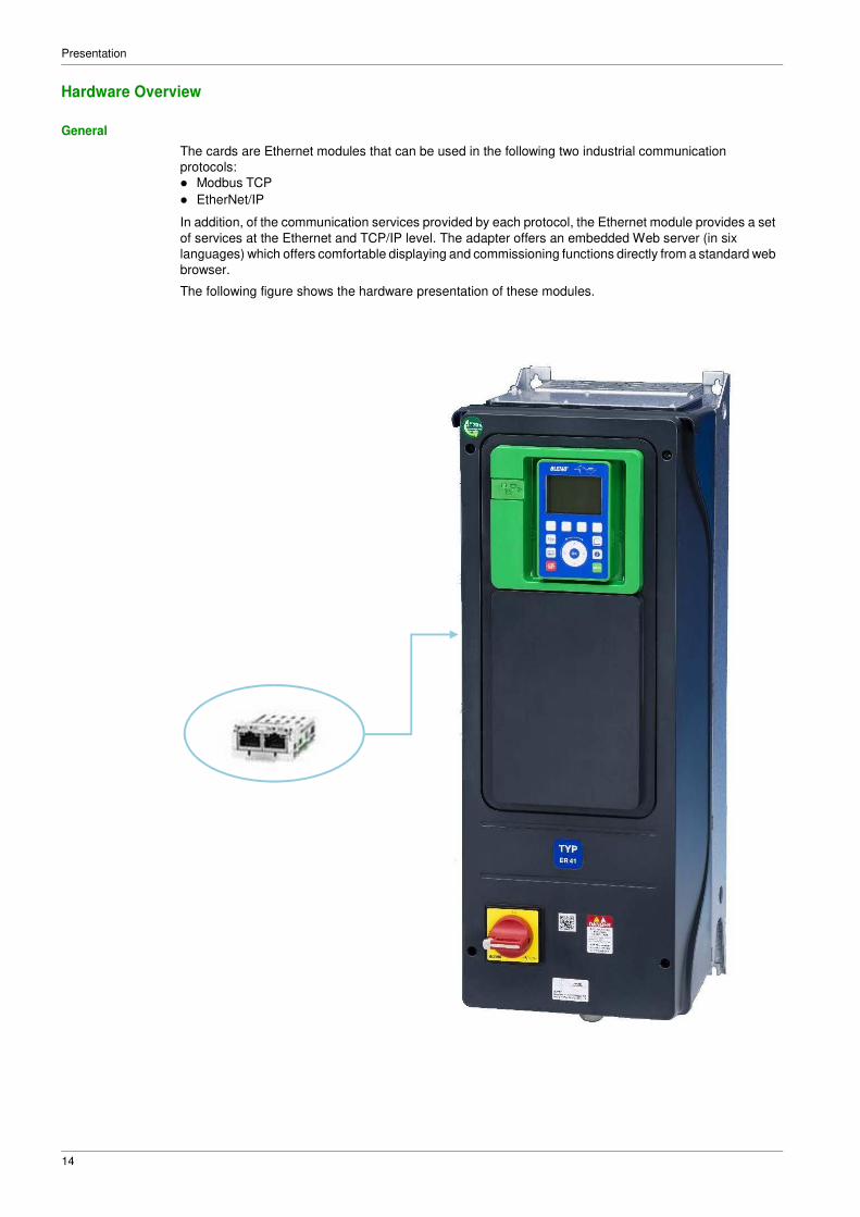
General
The cards are Ethernet modules that can be used in the following two industrial communication
protocols:
� Modbus TCP
� EtherNet/IP
In addition, of the communication services provided by each protocol, the Ethernet module provides a set
of services at the Ethernet and TCP/IP level. The adapter offers an embedded Web server (in six
languages) which offers comfortable displaying and commissioning functions directly from a standard web
browser.
The following figure shows the hardware presentation of these modules.
15
Presentation
Software Overview
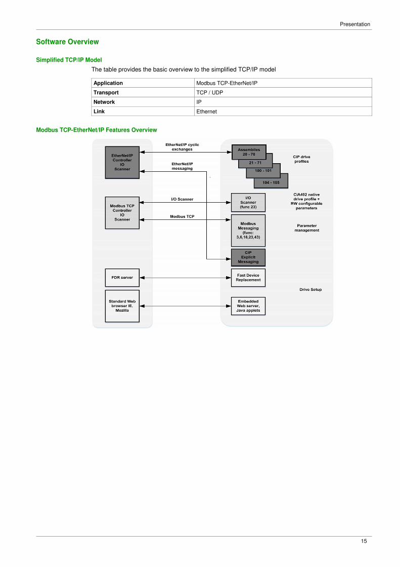
Simplified TCP/IP Model
The table provides the basic overview to the simplified TCP/IP model
Application Modbus TCP-EtherNet/IP
Transport TCP / UDP
Network IP
Link Ethernet
Modbus TCP-EtherNet/IP Features Overview

Presentation
16

17
Chapter 2 Basics
What Is in This Chapter?
This chapter contains the following sections:
Section Topic Page
2.1 Introduction 18
2.2 Modbus TCP Features 23
2.3 Ethernet IP Features 28
2.4 CIP Object 34

Basics
18
Section 2.1 Introduction
What Is in This Section?
This section contains the following topics:
Topic Page
Introduction 19
Network Layer Supported Functions/Protocols 20
TCP and UDP Protocol 21
Basics
19
Introduction
Modbus TCP
The Modbus application layer is standard. Many of the manufacturers are already implementing this
protocol. Many have already developed a Modbus TCP/IP connection and numerous products are
currently available. With the simplicity of its protocol and the fast Ethernet throughput data rate of
100 Mbit/s, Modbus TCP/IP achieves excellent performance.
EtherNet/IP
EtherNet/IP is a fieldbus based on TCP and UDP. EtherNet/IP extends Ethernet by an advanced industrial
protocol (CIP, Common Industrial Protocol) as an application layer for automation applications in this way,
Ethernet suites for industrial control. Products from different manufacturers can be networked without the
need for special interface adaptation.
TCP/IP and Ethernet Features
The product supports the following functions via:
� Manual IP address assignment
� Automatic IP address assignment via BOOTP or DHCP
� Automatic configuration data via FDR
� Commissioning via DTM-based commissioning software
� Diagnostics and configuration via integrated Web server
� Support of LLDP (Link Layer Discovery Protocol)
� Support of RSTP (Rapid Spanning Tree Protocol)
� Support of SNMP (Simple Network Management Protocol)
� Support of DNS (Domain Name System)
� Support of IPV6 for DPWS (Devices Profile for Web Services)
� Handling of QoS (Quality of Service)
Web Server
The standard webserver (in six languages) provides access to pages such as:
� My dashboard
� Display
� Diagnostics
� Drive
� Setup
MultiDrive Link Feature
The FK41 embeds, in addition of the features described above, the MultiDrive Link feature. This allow to use and give access to Multiple Pumps functions of ER41 range.
For more informations about commissioning of MultiDrive Link feature and Multiple Pumps functions, refer
to ER41 Programming Manual.

Basics
20
Network Layer Supported Functions/Protocols
ARP Protocol
The ARP (Address resolution protocol) is a protocol used to map network addresses (IP) to hardware
addresses (MAC).
The protocol operates below the network layer as a part of the OSI link layer, and is used when IP is used
over Ethernet. A host, wishing to obtain a physical address, broadcasts an ARP request onto the TCP/IP
network. A unique IP address is assigned to the host, and is sent to its hardware address.
ICMP Protocol
The FK41 Ethernet modules manage the ICMP protocol.
� ICMP client: not supported
� ICMP server: the managed requests are the following:
Type Description
0 Echo reply (ping)
3 Destination unreachable
4 Sources quench
5 Redirect
6 Alternate host address
8 Echo request (ping)
9 Router advertisement
10 Router solicitation
11 Time exceeded
12 Parameter problem
13 Time stamp request
14 Time stamp reply
15 Information request
16 Information reply
17 Address mask request
18 Address mask reply
IP Protocol
The Ethernet adapter implements the IPV4 and IPV6 (for DPWS) protocols.
SNMP Services
The Ethernet adapter accepts the community name “private” for writing and the community name “public”
for Reading.
MIB
Objects Description Access Default Value
SysDescr Text description of the product Read only BLEMO ER41 Ethernet TCP/IP
SysObjectID Points in the private MIB on the
product part number
Read only 1.3.6.1.4.1.3833.1.100.4.1
SysUpTime Time elapsed since the last power-
up
Read only Managed by the option
SysContact Information allowing to contact the
node manager
Read/write '' ''
SysName Node administrative name Read/write “” or FDR device name if configured
SysLocation Physical location of the product Read/write '' ''
SysService Indicates the service type offered by
the product.
Read only 72
Basics
21
TCP and UDP Protocol
Connections
The Ethernet adapter supports up to 32 concurrent TCP/IP and/or TCP/UDP connection.
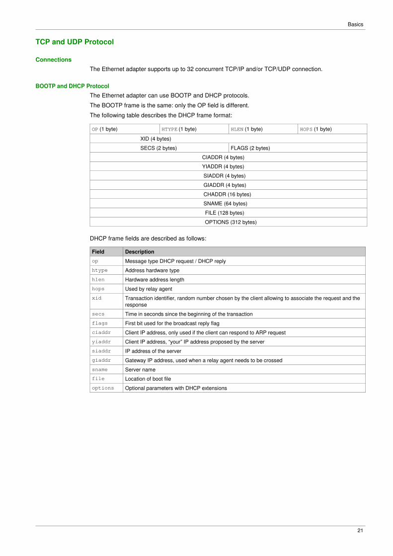
BOOTP and DHCP Protocol
The Ethernet adapter can use BOOTP and DHCP protocols.
The BOOTP frame is the same: only the OP field is different.
The following table describes the DHCP frame format:
OP (1 byte) HTYPE (1 byte) HLEN (1 byte) HOPS (1 byte)
XID (4 bytes)
SECS (2 bytes) FLAGS (2 bytes)
CIADDR (4 bytes)
YIADDR (4 bytes)
SIADDR (4 bytes)
GIADDR (4 bytes)
CHADDR (16 bytes)
SNAME (64 bytes)
FILE (128 bytes)
OPTIONS (312 bytes)
DHCP frame fields are described as follows:
Field Description
op Message type DHCP request / DHCP reply
htype Address hardware type
hlen Hardware address length
hops Used by relay agent
xid Transaction identifier, random number chosen by the client allowing to associate the request and the
response
secs Time in seconds since the beginning of the transaction
flags First bit used for the broadcast reply flag
ciaddr Client IP address, only used if the client can respond to ARP request
yiaddr Client IP address, “your” IP address proposed by the server
siaddr IP address of the server
giaddr Gateway IP address, used when a relay agent needs to be crossed
sname Server name
file Location of boot file
options Optional parameters with DHCP extensions

Basics
22
DHCP Message
The DHCP protocol uses 8 different types of message during the IP assigning process.
The following table describes the 8 messages:
Message Description
DISCOVER The client tries to discover the DHCP server using a broadcast
OFFER The server proposes a configuration
REQUEST The client chooses a DHCP server and declines other offers
ACK The chosen server assigns the IP configuration
NAK The server rejects the client request
DECLINE The client declines the assigned IP configuration
RELEASE The client releases Its IP address before the end of the lease
INFORM The client asks for network information (it already has an IP address)
Operating Modes
The choice between DHCP, BOOTP, and fixed configuration is made through one parameter:
� Fixed: the Ethernet adapter uses the address stored in parameter.
� BOOTP: the Ethernet adapter receives the addresses from BOOTP server.
� DHCP: if the device name [XXX] is valid, the Ethernet adapter receives the addresses from the DHCP
server.

Basics
23
Section 2.2 Modbus TCP Features
What Is in This Section?
This section contains the following topics:
Topic Page
Modbus TCP Frames 24
Modbus TCP Servers 25
Supported Modbus TCP Functions 26
Application Profile with Modbus TCP 27
Basics
24
Modbus TCP Frames
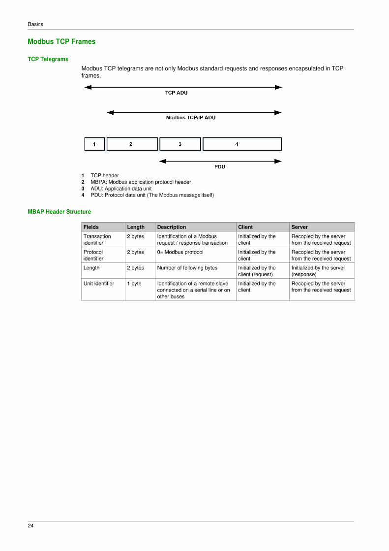
TCP Telegrams
Modbus TCP telegrams are not only Modbus standard requests and responses encapsulated in TCP
frames.
1 TCP header
2 MBPA: Modbus application protocol header
3 ADU: Application data unit
4 PDU: Protocol data unit (The Modbus message itself)
MBAP Header Structure
Fields Length Description Client Server
Transaction
identifier
2 bytes Identification of a Modbus
request / response transaction
Initialized by the
client
Recopied by the server
from the received request
Protocol
identifier
2 bytes 0= Modbus protocol Initialized by the
client
Recopied by the server
from the received request
Length 2 bytes Number of following bytes Initialized by the
client (request)
Initialized by the server
(response)
Unit identifier 1 byte Identification of a remote slave
connected on a serial line or on
other buses
Initialized by the
client
Recopied by the server
from the received request

Basics
25
Modbus TCP Servers
Overview
Unit ID Modbus TCP server Accessible parameters
0/248 Variable speed drive See the file related to drive communication parameters.
255 Drive I/O scanner See I/O scanner setting (see page 26)
Basics
26
Supported Modbus TCP Functions
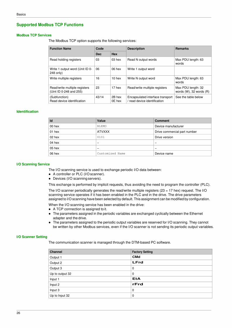
Modbus TCP Services
The Modbus TCP option supports the following services:
Function Name Code Description Remarks
Dec Hex
Read holding registers 03 03 hex Read N output words Max PDU length: 63
words
Write 1 output word (Unit ID 0-
248 only)
06 06 hex Write 1 output word
Write multiple registers 16 10 hex Write N output word Max PDU length: 63
words
Read/write multiple registers
(Uint ID 0-248 and 255)
23 17 hex Read/write multiple registers Max PDU length: 32
words (W), 32 words (R)
(Subfunction)
Read device identification
43/14 2B hex
0E hex
Encapsulated interface transport
/ read device identification
See the table below
Identification
Id Value Comment
00 hex BLEMO Device manufacturer
01 hex ATVXXX Drive commercial part number
02 hex 0101 Drive version
04 hex − −
05 hex − −
06 hex Customized Name Device name
I/O Scanning Service
The I/O scanning service is used to exchange periodic I/O data between:
� A controller or PLC (I/O scanner).
� Devices (I/O scanning servers).
This exchange is performed by implicit requests, thus avoiding the need to program the controller (PLC).
The I/O scanner periodically generates the read/write multiple registers (23 = 17 hex) request. The I/O
scanning service operates if it has been enabled in the PLC and in the drive. The drive parameters
assigned to I/O scanning have been selected by default. This assignment can be modified by configuration.
When the I/O scanning service has been enabled in the drive:
� A TCP connection is assigned to it.
� The parameters assigned in the periodic variables are exchanged cyclically between the Ethernet
adapter and the drive.
� The parameters assigned to the periodic output variables are reserved for I/O scanning. They cannot
be written by other Modbus services, even if the I/O scanner is not sending its periodic output variables.
I/O Scanner Setting
The communication scanner is managed through the DTM-based PC software.
Channel Factory Setting
Output 1 CMd
Output 2 LFrd
Output 3 0
Up to output 32 0
Input 1 EtA
Input 2 rFrd
Input 3 0
Up to Input 32 0

Basics
27
Application Profile with Modbus TCP
Description
The profiles managed with the drive when it is controlled through Modbus TCP are:
� Native profile (CiA402 - IEC 61800-7),
� I/O profile.
For details, refer to CiA®402 - IEC61800-7 functional profile

Basics
28
Section 2.3 Ethernet IP Features
What Is in This Section?
This section contains the following topics:
Topic Page
EtherNet/IP 29
Cyclical Exchanges (Implicit Exchanges) 30
Messaging (Explicit Exchanges) 33
Timeout Monitoring 33

Basics
29
EtherNet/IP
EtherNet/IP Fieldbus Module Features Overview
The Ethernet adapter, is compliant with the ODVA drive profile. It supports the following profiles:
� CIP basic speed control
� CIP extended speed control
� Drive native profile (IEC 61800-7 CiA402) and I/O profile only for assembly 100, 101, 104 and 105. In
addition to these cyclic exchanges, the adapter also supports explicit messaging.
� CIP energy objects

Basics
30
Cyclical Exchanges (Implicit Exchanges)
Overview
This part gives a description of the assembly sets and how to configure them.
Principle of Control Configuration
By the configuration of the control, it is possible to decide from which channel the drive receives its
commands and reference frequency, either permanently or depending on a switching command.
Numerous configurations are possible. For more information, refer to the programming manual and
communication parameters manual.The following configurations are some of the available possibilities.
The selection of the assembly set is made with the DTM.
Control with Communication Scanner
If the assemblies selected are 100 and 101, the drive is controlled according to its native profile CiA402.-
IEC-61800-7.
By configuring the communication scanner, it is possible to assign any relevant parameter of the drive to
the 32 input and 32 output variables of the assemblies. This is available through the DTM interface.
Control According to ODVA AC Drive Profile
The ODVA AC drive profile is activated when one of the following assemblies is selected:
� 20: Basic speed control output, size 2 words / 4 bytes
� 21: Extended speed control output, size 2 words / 4 bytes
� 70: Basic speed control input, size 2 words / 4 bytes
� 71: Extended speed control input, size 2 words / 4 bytes
The Ethernet adapter translates the commands, behavior, and display information from of ODVA profile
(on the network) to the CiA402 profile (in the drive).
CIP Basic Speed Control (Assemblies 20 and 70)
� Assembly 20: CIP basic speed control output
The following table describes the assembly mapping:
Word Number Definition
0 CIP basic command word
1 Speed reference (rpm)
The following table describes the CIP basic command word:
Bit 7 Bit 6 Bit 5 Bit 4 Bit 3 Bit 2 Bit 1 Bit 0
Not used Not used Not used Not used Not used Fault reset (1)
0: No command
1: Fault reset
Not used Run forward (2)
0: Stop
1: Run
(1) Active on rising edge (2) Active on level
Bit 15 Bit 14 Bit 13 Bit 12 Bit 11 Bit 10 Bit 9 Bit 8
Not used Not used Not used Not used Not used Not used Not used Not used

Basics
31
� Assembly 70: CIP basic speed control input
The following table describes the assembly mapping:
Word Number Definition
0 CIP basic status word
1 Actual speed (rpm)
The following table describes the CIP basic command word:
Bit 7 Bit 6 Bit 5 Bit 4 Bit 3 Bit 2 Bit 1 Bit 0
Not used Not used Not used Not used Not used Running
0: Stopped
1: Running
Not used Operating
state fault
0: Inactive
1: Active
Bit 15 Bit 14 Bit 13 Bit 12 Bit 11 Bit 10 Bit 9 Bit 8
Not used Not used Not used Not used Not used Not used Not used Not used
CIP Extended Speed Control (Assemblies 21 and 71)
� Assembly 21: CIP extended speed control output
The following table describes the assembly mapping:
Word Number Definition
0 CIP extended command word
1 Speed reference (rpm)
The following table describes the CIP extended command word:
Bit 7 Bit 6 Bit 5 Bit 4 Bit 3 Bit 2 Bit 1 Bit 0
Not used Network Network Not used Not used Fault reset (1) Run forward / reverse
setpoint command 0: No command 00: Quick stop
0: 0: 1: Fault reset 01: Run forward
Setpoint Setpoint 10: Run reverse
by by 11: No action
terminal terminal 1: 1: Setpoint Setpoint by by network network (1) Active on rising edge
Bit 15 Bit 14 Bit 13 Bit 12 Bit 11 Bit 10 Bit 9 Bit 8
Not used Not used Not used Not used Not used Not used Not used Not used

Basics
32
Network Setpoint and Network Address Management
The assembly 21 uses the command and reference frequency switching functions of the drive. The
Ethernet adapter, when configured with the assembly 21, links the bit 5 and the bit 6 to C312 and C313
respectively.
To operate correctly, command settings of the drive must be as follows or an [Fieldbus Error] EPF2 is
triggered.
Menu Parameter Settings
[Complete settings] CSt- [Control Mode] CHCF [Separate] SEP
/[Command and Reference] [Ref Freq 1 Config] Fr1 [Ref. Freq-Com. Module] nEt CrP- [Ref Freq 2 Config] Fr2 [Al1] AI1 or [Al2] AI2
[Cmd Channel 1] Cd1 [Com.Module] nEt
[Cmd Channel 2] Cd2 [Terminals] tEr
[Command Switching] CCS [C312] C312
[Ref Freq 2 switching] rFC [C313] C313
� Assembly 71: CIP extended speed control input
The following table describes the assembly mapping:
Word Number Definition
0 CIP extended status word
1 Actual speed (rpm)
The following table describes the CIP extended status word:
Bit 7 Bit 6 Bit 5 Bit 4 Bit 3 Bit 2 Bit 1 Bit 0
At reference Setpoint Comman Ready Run forward / reverse Warning Operating state
0: Reference from d from 0: Not 00: Stopped 0: No Warning fault
not reached network network ready 01: Running forward 1: Warning 0: Inactive
1: Reference 0: 0: 1: Ready 10: Running reverse 1: Active
reached Setpoint Setpoint 11: Not used from from terminal terminal 1: 1: Setpoint Setpoint from from network network
Bit 15 Bit 14 Bit 13 Bit 12 Bit 11 Bit 10 Bit 9 Bit 8
Not used Not used Not used Not used Not used Bit 8 to 10 are used for the drive state
000: Not used
001: Startup
010: Not ready
011: Ready
100: Enabled
101: Stopping
110: Fault stop
111: Operating state fault

Basics
33
Messaging (Explicit Exchanges)
Introduction
Parameters of the drive can be accessed by R/W as CIP objects.
ER41 Parameters Path
The drive parameters are grouped in classes:
� Each application class has only one instance.
� Each instance groups 200 parameter.
� Each attribute in an instance relates to a parameter.
The first parameter registered in the first application class (class code: 70 hex = 112) has the logical
address 3000.
Example
The following table describes the examples of logical addresses:
Logical Address Hexadecimal Decimal
3000 70 hex / 01 hex / 01 hex 112/1/1
3100 70 hex / 01 hex / 65 hex 112/1/101
3200 71 hex / 01 hex / 01 hex 113/1/1
64318 A2 hex / 01 hex / 77 hex 418/1/119
For details, refer to the communication parameters manual.
Timeout Monitoring
Description
An EtherNet/IP time-out is triggered if the adapter does not receive any cyclic messages within a
predefined time period. This period is managed by the EtherNet/IP controller (not by the drive) and is
configured in its module properties box. The duration of the time-out is defined by the RPI (Request packet
intervals) and a multiplier.

Basics
34
Section 2.4 CIP Object
What Is in This Section?
This section contains the following topics:
Topic Page
Supported Object Classes 35
Identity Object (01 hex) 36
Message Router Object (02 hex) 39
TCP/IP Interface Object (F5 hex) 40
Ethernet Link Object (F6 hex) 43
Assembly Object (04 hex) 45
Connection Manager Object (06 hex) 47
Motor Data Object (28 hex) 49
Control Supervisor Object (29 hex) 50
AC/DC Drive Object (2A hex) 52
Application Object (70 hex to C7 hex) / Explicit Messaging 55
Base Energy Object (4E hex) 56
Electrical Energy Object (4F hex) 58
Basics
35
Supported Object Classes
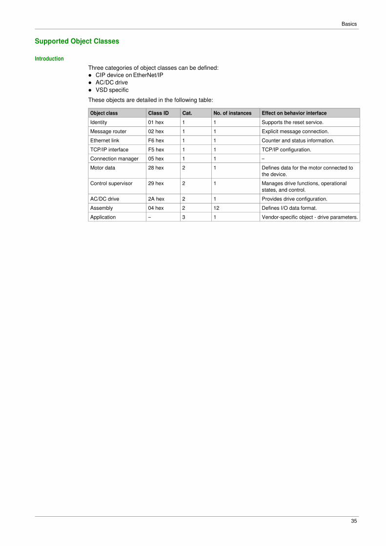
Introduction
Three categories of object classes can be defined:
� CIP device on EtherNet/IP
� AC/DC drive
� VSD specific
These objects are detailed in the following table:
Object class Class ID Cat. No. of instances Effect on behavior interface
Identity 01 hex 1 1 Supports the reset service.
Message router 02 hex 1 1 Explicit message connection.
Ethernet link F6 hex 1 1 Counter and status information.
TCP/IP interface F5 hex 1 1 TCP/IP configuration.
Connection manager 05 hex 1 1 –
Motor data 28 hex 2 1 Defines data for the motor connected to
the device.
Control supervisor 29 hex 2 1 Manages drive functions, operational
states, and control.
AC/DC drive 2A hex 2 1 Provides drive configuration.
Assembly 04 hex 2 12 Defines I/O data format.
Application – 3 1 Vendor-specific object - drive parameters.

Basics
36
Identity Object (01 hex)
Overview
The identity object provides identification and status information about the drive.
Class Code
Hexadecimal Decimal
01 hex 1
Class Attributes
Attribute ID Access Name Data type Value Details
1 Get Revision UNIT X Revision index of the class
2 Get Max instances UNIT 1 1 defined instance
3 Get Number of instances UNIT 1 –
4 Get Optional attribute
list
UNIT 1 –
6 Get Max ID of
class attributes
UNIT 7 –
7 Get Max ID of
instance attribute
UNIT 7 –
Instance Attributes
Attribute ID Access Name Data type Value Details
1 Get Vendor ID UNIT 243 –
2 Get Device type UNIT 00 h
02 h
AC/DC drive profile (02h)
3 Get Product code UNIT 6152 1830 hex
4 Get Revision Struct of:
USINT
USINT
x Major = high byte of (C1SU)
Minor = low byte of (C1SU)
5 Get Status WORD – See definition in the following table
6 Get Serial number UDINT – First byte: 18 hex
Second…Fourth byte: last 3 bytes of
MAC-ID
7 Get Product name Struct of:
USINT
STRING
– ATVxxx
Attribute 5–Status
Bit Definition How
0 Owned by master (predefined
master/slave connection)
No interface
2 Configured If any of the product (option + drive) NVS attributes has changed
from their default (out of box values).
4 - 7 Extended device status: See
below
–
8 Minor recoverable Fault No minor recoverable fault.
9 Minor unrecoverable Fault No minor unrecoverable fault.
10 Major recoverable Fault [Fieldbus Com Interrupt] CnF detected error or CIP connection
timeout or Ethernet network overload.
11 Major unrecoverable Fault ILF detected error, EEPROM failed, OB hardware detected error.
Others Reserved 0 –
Basics
37
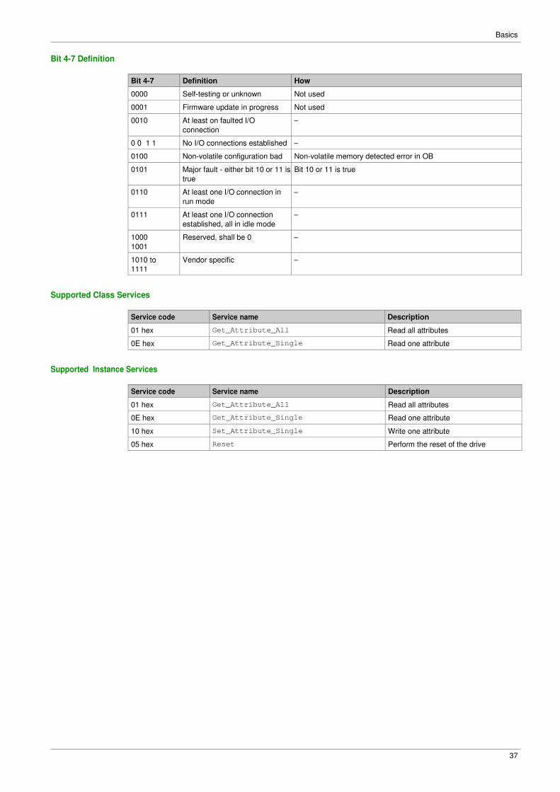
Bit 4-7 Definition
Bit 4-7 Definition How
0000 Self-testing or unknown Not used
0001 Firmware update in progress Not used
0010 At least on faulted I/O
connection
–
0 0 1 1 No I/O connections established –
0100 Non-volatile configuration bad Non-volatile memory detected error in OB
0101 Major fault - either bit 10 or 11 is
true
Bit 10 or 11 is true
0110 At least one I/O connection in
run mode
–
0111 At least one I/O connection
established, all in idle mode
–
1000
1001
Reserved, shall be 0 –
1010 to
1111
Vendor specific –
Supported Class Services
Service code Service name Description
01 hex Get_Attribute_All Read all attributes
0E hex Get_Attribute_Single Read one attribute
Supported Instance Services
Service code Service name Description
01 hex Get_Attribute_All Read all attributes
0E hex Get_Attribute_Single Read one attribute
10 hex Set_Attribute_Single Write one attribute
05 hex Reset Perform the reset of the drive

Basics
38
State Diagram for the Identity Object
Basics
39
Message Router Object (02 hex)
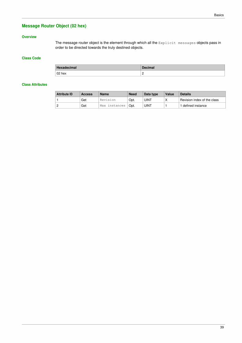
Overview
The message router object is the element through which all the Explicit messages objects pass in
order to be directed towards the truly destined objects.
Class Code
Hexadecimal Decimal
02 hex 2
Class Attributes
Attribute ID Access Name Need Data type Value Details
1 Get Revision Opt. UINT X Revision index of the class
2 Get Max instances Opt. UINT 1 1 defined instance

Basics
40
TCP/IP Interface Object (F5 hex)
Supported Class Attributes
Attribute ID Access Name Data type Value Detail
1 Get Revision UINT X Revision index of the class
2 Get Max instances UINT 1 1 defined instance
3 Get Number of instances UINT 1 –
4 Get Optional attribute list UINT 1 –
5 Get Optional service list UINT 1 –
6 Get Max ID of class
attributes
UINT 7 –
7 Get Max ID of
instance attribute
UINT 6 –
Supported Instance Attributes
Attribute ID Access Name Data type Detail
1 Get Status DWORD 0 = The interface configuration attribute has not
been configured
1 = The interface configuration attribute
contains valid configuration
2 Get Configuration cap
ability
DWORD Bit 0 = 1 (TRUE) shall indicate that the device
is capable of obtaining its network
configuration via BOOTP
Bit 1 = 1 (TRUE) shall indicate that the device
is capable of resolving host names by querying
a DNS server
Bit 2 = 1 (TRUE) shall indicate that the device
is capable of obtaining its network
configuration via DHCP
Bit 3 = 1 (TRUE) shall indicate that the device
is capable of sending its host name in the
DHCP request
Bit 4 = 1 (TRUE) shall indicate that the
Interface Configuration attribute is settable.
Bit 5-31: reserved
3 Get/Set Configuration con
trol
DWORD Bits 0-3 start-up configuration
0 = The device shall use the interface
configuration values previously stored
1 = The device shall obtain its interface
configuration values via BOOTP
2 = The device shall obtain its interface
configuration values via DHCP upon start-up (1)
3-15 = Reserved for future use
Bit 4 = 1 (TRUE), the device shall resolve host
names by querying a DNS server
Bit 5-31: reserved
4 Get Physical link
object
STRUCT of
UINT
EPATH
Path size
Path: Logical segments identifying the physical
link object
Example [20][F6][24][01]: [20] = 8-bit class
segment type;
[F6] = Ethernet link object class; [24] = 8-bit
instance segment type; [01] = instance 1
(1) If set option board parameter OBP:FDRU=0 is also set to implicitly disable the FDR mechanism on the DHCP
protocol. This to be compatible with CIP tools that has configured the device to operate in a non-FDR specific
environment. You have to manually enable the feature if you wish to use it.
Basics
41
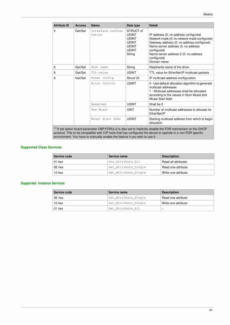
Attribute ID Access Name Data type Detail
5 Get/Set Interface configu
ration
STRUCT of
UDINT
UDINT
UDINT
UDINT
UDINT
String
IP address (0: no address configured)
Network mask (0: no network mask configured)
Gateway address (0: no address configured)
Name server address (0: no address
configured)
Name server address 2 (0: no address
configured)
Domain name
6 Get/Set Host name String Read/write name of the drive
8 Get/Set TTL value USINT TTL value for EtherNet/IP multicast packets
9 Get/Set Mcast config Struct Of. IP multicast address configuration
Alloc control USINT 0 - Use default allocation algorithm to generate
multicast addresses
1 - Multicast addresses shall be allocated
according to the values in Num Mcast and
Mcast Start Addr
Reserved USINT Shall be 0
Num Mcast UINT Number of multicast addresses to allocate for
EtherNet/IP
Mcast Start Addr UDINT Starting multicast address from which to begin
allocation
(1) If set option board parameter OBP:FDRU=0 is also set to implicitly disable the FDR mechanism on the DHCP
protocol. This to be compatible with CIP tools that has configured the device to operate in a non-FDR specific
environment. You have to manually enable the feature if you wish to use it.
Supported Class Services
Service code Service name Description
01 hex Get_Attribute_All Read all attributes
0E hex Get_Attribute_Single Read one attribute
10 hex Set_Attribute_Single Write one attribute
Supported Instance Services
Service code Service name Description
0E hex Get_Attribute_Single Read one attribute
10 hex Set_Attribute_Single Write one attribute
01 hex Get_Attribute_All –
Basics
42
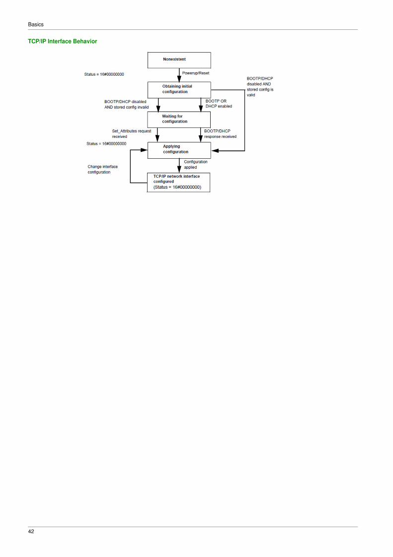
TCP/IP Interface Behavior
Basics
43
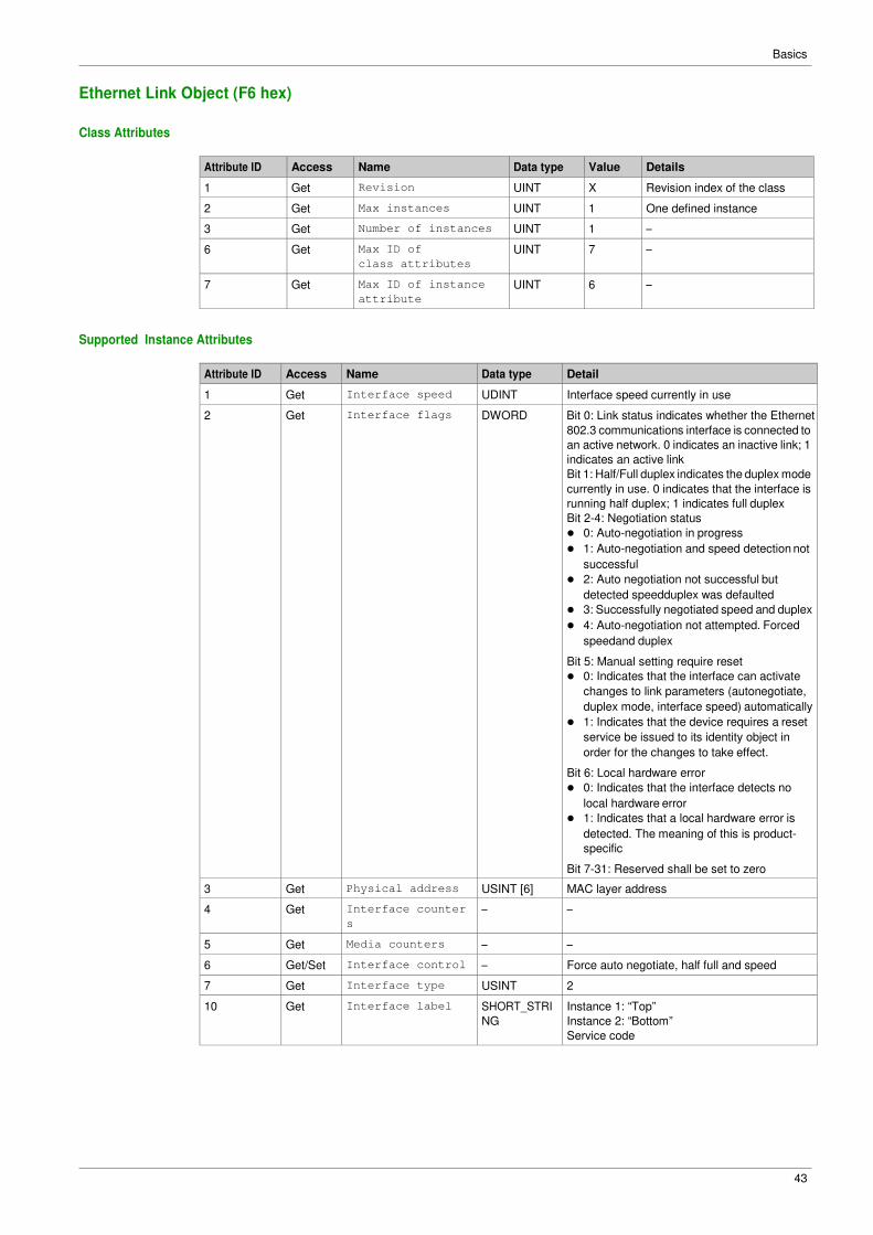
Ethernet Link Object (F6 hex)
Class Attributes
Attribute ID Access Name Data type Value Details
1 Get Revision UINT X Revision index of the class
2 Get Max instances UINT 1 One defined instance
3 Get Number of instances UINT 1 –
6 Get Max ID of
class attributes
UINT 7 –
7 Get Max ID of instance
attribute
UINT 6 –
Supported Instance Attributes
Attribute ID Access Name Data type Detail
1 Get Interface speed UDINT Interface speed currently in use
2 Get Interface flags DWORD Bit 0: Link status indicates whether the Ethernet
802.3 communications interface is connected to
an active network. 0 indicates an inactive link; 1
indicates an active link
Bit 1: Half/Full duplex indicates the duplex mode
currently in use. 0 indicates that the interface is
running half duplex; 1 indicates full duplex
Bit 2-4: Negotiation status
� 0: Auto-negotiation in progress
� 1: Auto-negotiation and speed detection not
successful
� 2: Auto negotiation not successful but
detected speedduplex was defaulted
� 3: Successfully negotiated speed and duplex
� 4: Auto-negotiation not attempted. Forced
speedand duplex
Bit 5: Manual setting require reset
� 0: Indicates that the interface can activate
changes to link parameters (autonegotiate,
duplex mode, interface speed) automatically
� 1: Indicates that the device requires a reset
service be issued to its identity object in
order for the changes to take effect.
Bit 6: Local hardware error
� 0: Indicates that the interface detects no
local hardware error
� 1: Indicates that a local hardware error is
detected. The meaning of this is product-
specific
Bit 7-31: Reserved shall be set to zero
3 Get Physical address USINT [6] MAC layer address
4 Get Interface counter
s
– –
5 Get Media counters – –
6 Get/Set Interface control – Force auto negotiate, half full and speed
7 Get Interface type USINT 2
10 Get Interface label SHORT_STRI
NG
Instance 1: “Top”
Instance 2: “Bottom”
Service code

Basics
44
Supported Class Services
Service code Service name Description
0E hex Get_Attribute_Single Read one attribute
01 hex Get_Attribute_All –
Supported Instance Services
Service code Service name Description
0E hex Get_Attribute_Single Read one attribute
10 hex Set_Attribute_Single Write one attribute
01 hex Get_Attribute_All –
4C hex Get_And_Clear Same than Get_Attribute_Single

Basics
45
Assembly Object (04 hex)
Supported Class Attributes
Attribute ID Access Name Data type Value Detail
1 Get Revision UINT X Revision index of the class
2 Get Max instances UINT 1 One defined instance
3 Get Number of instances UINT 1 –
6 Get Max ID of
class attributes
UINT 7 –
7 Get Max ID of
instance attribute
UINT 3 –
Supported Instances
Attribute ID Access Name Data type Value Details
3 Get/Set Data ARRAY OF BYTE
4 Get Size UINT
Supported Instances for ER41
Instance Type Name
20 AC drive output CIP Basic Speed Control Output
21 AC drive output CIP Extended Speed Control Output
70 AC drive input CIP Basic Speed Control Input
71 AC drive input CIP Extended Speed Control Input
100 AC drive output Native Drive Output
101 AC drive input Native Drive Input
Supported Class Services
Service code Service Name Description
0E hex Get_Attribute_Single Read one attribute
Supported Instance Services
Service Code Service Name Description
0E hex Get_Attribute_Single Read one attribute
10 hex Set_Attribute_Single Write one attribute
Output Instance Data Description
Instance Byte Bit 7 Bit 6 Bit 5 Bit 4 Bit 3 Bit 2 Bit 1 Bit 0
20 0 X X X X X Fault Reset
0 = No
command
1= Fault Reset
X Run Forward
0 = Stop
1 = Run
1 X X X X X X X X
2-3 Speed Actual (rpm)
21 0 X Net
Reference
0 = Local, by
terminal
1= Network
NetComman
d
0 = Local
1 = Network
X X Fault Reset
0 = No
command
1= Fault Reset
Run Fwd / Reverse:
00: Quick stop
01: Run forward
10: Run reverse
11: No action
1 X X X X X X X X
2-3 Speed Actual (rpm)

Basics
46
Instance Byte Bit 7 Bit 6 Bit 5 Bit 4 Bit 3 Bit 2 Bit 1 Bit 0
100 0-1 I/O Scanning word 1
2-3 I/O Scanning word 2
4-5 I/O Scanning word 3
6-7 I/O Scanning word 4
8-9 I/O Scanning word 5
10-11 I/O Scanning word 6
70 0 X X X X X 0 = Stopped
1 = Running
X 0 = No error
1 = Error
1 X X X X X X X X
2-3 Speed Actual (rpm)
71 0 At reference
0 = Not
reached
1 = Reached
Ref From Net
0 = From
terminal
1 = From
network
Cmd From
Net
0 = From
terminal
1 = From
network
Ready
0 = Not
ready
1 =Ready
Running Fwd / reverse
00: Stopped
01: Running Forward
10: Running reverse
11: Not used
Warning
0 = No
warning
1 = Warning
Not used
1 X X X X X 000: Not used
001: Startup
010: Not ready
011: Ready
100: Enabled
101: Stopping
110: Fault stop
111: Operating state fault
2-3 Speed Actual (rpm)
101 0-1 Scanner Read word 1
2-3 Scanner Read word 2
4-5 Scanner Read word 3
6-7 Scanner Read word 4
8-9 Scanner Read word 5
10-11 Scanner Read word 6

Basics
47
Connection Manager Object (06 hex)
Class Code
Hexadecimal Decimal
06 hex 6
Class Attributes
Attribute ID Access Name Need Data type Value Details
1 Get Revision Opt. UINT X Revision index of the class
2 Get Max instances Opt. UINT 4 3 defined instance
Attributes of Instance 1 - Explicit Message Instance
Attribute Access Name Need Data type Value Details
1 Get State Req. USINT – 0: Non-existent
3: Established
5: Deferred Delete
2 Get Instance_type Req. USINT 0 Explicit Message
3 Get TransportClass_trigge
r
Req. BYTE 83 hex Class 3 server
4 Get Produced_connection_i
d
Req. UINT 10xxxxxx01
1
xxxxxx = Node address
5 Get Consumed_connection_i
d
Req. UINT 10xxxxxx10
0
xxxxxx = Node address
6 Get Initial_comm_characte
ristics
Req. BYTE 21 hex Explicit messaging via
Group 2
7 Get Produced_connection_s
ize
Req. UINT 36 Produced data
maximum size (in
bytes)
8 Get Consumed_connection_s
ize
Req. UINT 36 Consumed data
maximum size (in
bytes)
9 Get/Set Expected_packet_rate Req. UINT 2500 2.5 sec. (TimeOut)
12 Get/Set Watchdog_timeout_acti
on
Req. USINT 1 or 3 1: Auto-Delete
3: Deferred Delete
(Default)
13 Get Produced connection
path length
Req. UINT 0 Length of attribute 14
data
14 Get Produced connection
path
Req. Array of
UINT
Null Not used
15 Get Consumed connection
path length
Req. UINT 0 Length of attribute 16
data
16 Get Consumed connection
path
Req. Array of
UINT
Null Not used
For details, refer to Ethernet/ specification for more information.
Basics
48
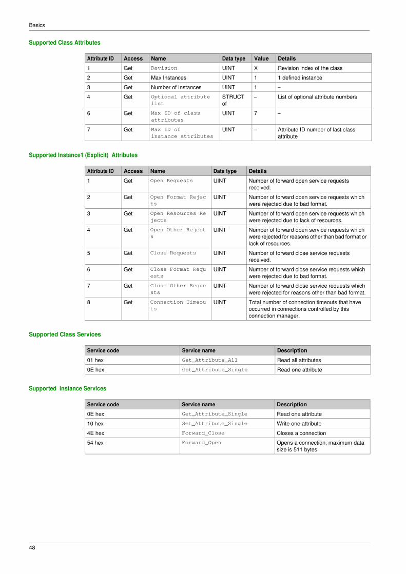
Supported Class Attributes
Attribute ID Access Name Data type Value Details
1 Get Revision UINT X Revision index of the class
2 Get Max Instances UINT 1 1 defined instance
3 Get Number of Instances UINT 1 –
4 Get Optional attribute
list
STRUCT
of
– List of optional attribute numbers
6 Get Max ID of class
attributes
UINT 7 –
7 Get Max ID of
instance attributes
UINT – Attribute ID number of last class
attribute
Supported Instance1 (Explicit) Attributes
Attribute ID Access Name Data type Details
1 Get Open Requests UINT Number of forward open service requests
received.
2 Get Open Format Rejec
ts
UINT Number of forward open service requests which
were rejected due to bad format.
3 Get Open Resources Re
jects
UINT Number of forward open service requests which
were rejected due to lack of resources.
4 Get Open Other Reject
s
UINT Number of forward open service requests which
were rejected for reasons other than bad format or
lack of resources.
5 Get Close Requests UINT Number of forward close service requests
received.
6 Get Close Format Requ
ests
UINT Number of forward close service requests which
were rejected due to bad format.
7 Get Close Other Reque
sts
UINT Number of forward close service requests which
were rejected for reasons other than bad format.
8 Get Connection Timeou
ts
UINT Total number of connection timeouts that have
occurred in connections controlled by this
connection manager.
Supported Class Services
Service code Service name Description
01 hex Get_Attribute_All Read all attributes
0E hex Get_Attribute_Single Read one attribute
Supported Instance Services
Service code Service name Description
0E hex Get_Attribute_Single Read one attribute
10 hex Set_Attribute_Single Write one attribute
4E hex Forward_Close Closes a connection
54 hex Forward_Open Opens a connection, maximum data
size is 511 bytes

Basics
49
Motor Data Object (28 hex)
Supported Class Attributes
Attribute ID Access Name Data type Value Details
1 Get Revision UINT X Revision index of the class
2 Get Max Instances UINT 1 One defined instance
3 Get Number of Instances UINT 1 –
6 Get Max ID of class attribu
tes
UINT 7 –
7 Get Max ID of
instance attribute
UINT 15 –
Supported Instance Attributes
Attribute ID Access Name Need Data type ATV Details
1 Get NumAttr Opt. USINT No –
2 Get Attributes List Opt. USINT
(ARRAY)
No –
3 Get MotorType Req. USINT Yes 7
6 Get/Set RatedCurrent Req. UINT Yes Motor nominal current
Linked to NCR drive
parameter.
NCR unit is 0,1 A as
attribute 6
7 Get/Set RatedVoltage Req. UINT Yes Motor nominal voltage
Linked to UNS drive
parameter
UNS unit is 1 V as attribute
7
8 Get/Set RatedPower Opt. UINT No –
9 Get/Set RatedFreq Opt. UINT Yes Motor nominal frequency
linked to FRS drive
parameter FRS unit is
0,1 Hz.
The parameter value has to
be divided by 10 to be in the
unit of attribute 9
12 Get/Set PoleCount Opt. UINT No –
15 Get/Set BaseSpeed Opt. UINT Yes Motor nominal speed
Linked to NSP drive
parameter
NSP unit is 1 rpm as
attribute 15
Supported Class Services
Service code Service name Description
0E hex Get_Attribute_Single Read one attribute
Supported Instance Services
Service code Service name Description
0E hex Get_Attribute_Single Read one attribute
10 hex Set_Attribute_Single Write one attribute

Basics
50
Control Supervisor Object (29 hex)
Supported Class Attributes
Attribute ID Access Name Data type Value Details
1 Get Revision UINT X Revision index of the class
2 Get Max Instances UINT 1 One defined instance
3 Get Number of Instances UINT 1 –
6 Get Max ID of class attrib
utes
UINT 7 –
7 Get Max ID of
instance attribute
UINT 17 –
Supported Instance Attributes for Schneider Electric
Attribute ID Access Name Data type Details
3 Get/Set Run Fwd BOOL On edge (0 --> 1)
4 Get/Set Run Rev BOOL On edge (0 --> 1)
5 Get/Set Net Ctrl BOOL 0: Local control
1: Network control (default)
6 Get State USINT See machine status:
0:
1: Startup
2: Not_Ready
3: Ready
4: Enabled
5: Stopping
6: Fault_stop
7: Operating state fault
7 Get Running Fwd BOOL ETA.15 = 0
8 Get Running Rev BOOL ETA.15 = 1
9 Get Ready BOOL ETA.1 = 1
10 Get Error detected BOOL ETA.3 = 1
12 Get/Set Fault Reset BOOL CMD.7 = 1.
13 Get Error Code USINT Parameter Errd
15 Get Ctrl From Net BOOL 0: Local Control
1: Network Control
16 Get/Set DN Error Mode USINT Action on loss of CIP network.
0: Stop + [Fieldbus Com Interrupt] CnF
detected error
1: Ignored
17 Get/Set Force error BOOL Force [Fieldbus Com Interrupt] CnF detected
error (On edge)
Supported Class Services
Service code Service name Description
0E hex Get_Attribute_Single Read one attribute
Supported Instance Services
Service code Service name Description
0E hex Get_Attribute_Single Read one attribute
10 hex Set_Attribute_Single Write one attribute
05 hex Reset Reset drive
Basics
51
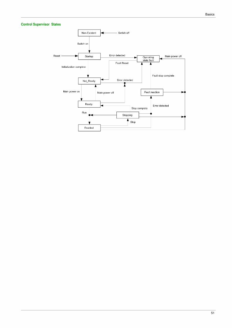
Control Supervisor States

Basics
52
AC/DC Drive Object (2A hex)
Supported Class Attributes
Attribute ID Access Name Data type Value Details
1 Get Revision UINT X Revision index of the class
2 Get Max Instances UINT 1 1 defined instance
3 Get Number of Instances UINT 1 –
6 Get Max ID of
class attributes
UINT 7 –
7 Get Max ID of
instance attribute
UINT 21 –
Supported Instance
Attribute ID Access Name Need Data type ATV Comments
1 Get NumAttr Opt. USINT No –
2 Get Attributes List Opt. USINT
(ARRAY)
No –
3 Get At Reference Opt. BOOL Yes Use the result of the “reference reached”
function of the device.
No more, no less specific adjustment than
what is in the drive function.
4 Get/Set NetRef Req. BOOL Yes Image of the NetRef signal received from
the network.
'Get' order returns the value written by 'Set'
order.
Used to manage the reference channel.
6 Get Drive mode Req. USINT Yes Used to get the drive mode.
In the standard, the attribute can also be
used to set the drive mode, but it is not
possible on our products.
Value is fixed at 1.
NOTE: On other drives this value main
depends on the Motor control law set in the
device.
7 Get Speed Actual Req. INT Yes Used to get the value of the motor Speed.
Unit: rpm
8 Get/Set SpeedRef Req. INT Yes Image of the speed reference signal
received from the network.
Unit: rpm
'Get' order returns the value written by 'Set'
order Used to set the speed reference in
the drive.
9 Get Current Actual Opt. INT Yes Used to get the value of the current in the
motor.
Unit: 0.1 Amps
10 Get/Set Current Limit Opt. INT Yes Used to set or get the current value used for
the motor thermal protection.
Unit: 0,1 Amps.
11 Get Torque Actual Opt. INT Yes Used to get the value of the motor torque.
Unit: 1 N.m
15 Get Power Actual Opt. INT No Used to get the value of the output power.
Unit 1 <--> 1/2PowerScale.
(1) For the standard, the acceleration, and deceleration time are given to go from 0 to [HighSpdLimit] (attribute 21 of AC/DC drive object). For
the drive, the acceleration and deceleration time are given to go from 0 to the motor nominal frequency (FrS parameter).
(2) In the drive, the unit of acceleration and deceleration time depends on INR parameter.
Inr = 0: acceleration and deceleration time are in 0,01 s
Inr = 1 (factory setting): acceleration and deceleration time are in 0,1 s
Inr = 2: acceleration and deceleration time are in 1 s

Basics
53
Attribute ID Access Name Need Data type ATV Comments
18 Get/Set AccelTime Opt. UINT Yes Used to get and set the acceleration
time(1)(2)
19 Get/Set DecelTime Opt. UINT Yes Used to get and set the deceleration
time(1)(2)
20 Get/Set LowSpdLimit Opt. UINT Yes Used to get and set the low speed limit.
Units: rpm
21 Get/Set HighSpdLimit Opt. UINT Yes Used to get and set the high speed limit.
Units: rpm
26 Get/Set PowerScale Opt. SINT No –
28 Get/Set TimeScale Opt. SINT No Default value = 0
29 Get RefFromNet Opt. BOOL No Used to know if the drive is processing the
reference sent by the network that asks the
attribute 29 value
46 Get Cumulative Run
Time
Brand UINT No Cumulative run time
(1) For the standard, the acceleration, and deceleration time are given to go from 0 to [HighSpdLimit] (attribute 21 of AC/DC drive object). For
the drive, the acceleration and deceleration time are given to go from 0 to the motor nominal frequency (FrS parameter).
(2) In the drive, the unit of acceleration and deceleration time depends on INR parameter.
Inr = 0: acceleration and deceleration time are in 0,01 s
Inr = 1 (factory setting): acceleration and deceleration time are in 0,1 s
Inr = 2: acceleration and deceleration time are in 1 s
Attribute ID Details
3 Attribute value = value of bit 10 of ETA drive parameter
7 Motor speed.
Linked to rFrd drive parameter.
(rFrd is in 1 rpm as attribute 7
8 Speed reference.
Linked to LFrd drive parameter.
LFrd is in 1 rpm as attribute 8
9 Actual current in the motor.
Linked to LCr drive parameter.LCr is in 0,1 A as attribute 9
10 Current value used for the motor thermal protection.
Linked to ItH drive parameter.
ItH is in 0,1 A as attribute 10
11 Actual torque in the motor.
Linked to Otrn drive parameter.
Otrn is in 0,1 N.m.
The value has to be multiplied by 10 to be in the unit of attribute 11
18 Acceleration time.
Linked to ACC drive parameter.
See note (2) of the specification above
19 Deceleration time.
Linked to DEC drive parameter.
See note (2) of the specification above
20 Low speed.
Linked to SMIL drive parameter.
SMIL is in 1 rpm as attribute 20
21 High speed.
Linked to SMAL drive parameter.
SMAL is in 1 rpm as attribute 21
Supported Class Services
Service code Service name Description
0E hex Get_Attribute_Single Read one attribute

Basics
54
Supported Instance Services
Service code Service name Description
0E hex Get_Attribute_Single Read one attribute
10 hex Set_Attribute_Single Write one attribute

Basics
55
Application Object (70 hex to C7 hex) / Explicit Messaging
Application Object Behavior
Class = ((AdL - 3000) / 200) + 70 hex
Instance = 1
Attribute = (AdL % 200) + 1
AdL = (class - 70 h) * 200 + attribute - 1 + 3000
This rule allows the access to address under 20599. The other addresses are not accessible.
The drive parameters are grouped into classes.
� Each application class has only one instance.
� Each instance groups 200 parameters.
� Each attribute in an instance relates to a parameter.
Supported Class Attributes
Attribute ID Access Name Data type Value Details
1 Get Revision UINT X Revision index of the class
2 Get Max Instances UINT 1 One defined instance
3 Get Number of Instances UINT 1 –
6 Get Max ID of class
attributes
UINT 7 –
7 Get Max ID of instance
attribute
UINT X –
Supported Instance Attributes
Attribute ID Access Name Data type Details
1 Get/Set 1st parameter of
the block
UINT Value returned by the drive at address xx
– – – – Value returned by the drive at address xx
X Get/Set Last parameter of the
block
UINT Value returned by the drive at address xx
Supported Class Services
Service code Service name Description
0E hex Get_Attribute_Single Read one attribute
Supported Instance Services
Service code Service name Description
0E hex Get_Attribute_Single Read one attribute
10 hex Set_Attribute_Single Write one attribute

Basics
56
Base Energy Object (4E hex)
Overview
The base energy object acts as an Energy Supervisor for CIP Energy implementations. It is responsible
for providing a time base for energy values, provides energy mode services, and can provide aggregation
services for aggregating energy values up through the various levels of an industrial facility. It also provides
a standard format for reporting energy metering results.
Class Code
Hexadecimal Decimal
4E hex 78
Class Attributes
Attribute ID Access Name Data type Value Details
1 Get Revision UINT X Revision index of the class
2 Get Max instances UINT 1 1 defined instance
3 Get Number of instances UINT 1 –
Instance Attributes
Attribute ID Access Name Data type Value Details
1 Get Energy/Resource
Type
UINT 1 1 = Electrical
2 Get Base Energy
Object
Capabilities
UINT – See definition in the following table
3 Get Energy Accuracy UINT – See definition in the following table
4 Get Energy Accuracy
Basis
UINT – See definition in the following table
7 Get Consumed Energy
Odometer
ODOMETE
R
– The consumed energy value in kWh
8 Get Generated Energy
Odometer
ODOMETE
R
– The generated energy value in kWh
9 Get Net Energy Odometer SIGNED_O
DOMETER
– The generated energy value in kWh
The following table provides the Odometer and Signed_Odometer structure principle:
Data Type Structure Description of Data Type
Element
Semantics of Value
ODOMETER STRUCT of: SIGNED_ODOMETER
STRUCT of:
– –
UINT INT x10n ±Unit1 x 10n
UINT INT x10n+3 ±Unit1 x 10n+3
UINT INT x10n+6 ±Unit1 x 10n+6
UINT INT x10n+9 ±Unit1 x 10n+9
UINT INT x10n+12 ±Unit1 x 10n+12
The valid range of n shall be a SINT between 0 and -15.
The following table provides the Odometer type in Kilowatt-hours units and n = -3:
x10n+12 x10n+9 x10n+6 x10n+3 x10n
Terawatt-hours
(kWh x 109)
Gigawatt-hours
(kWh x 106)
Megawatt-hours
(kWh x 103)
Kilowatt-hours (kWh) Watt-hours
(kWh x 10-3)

Basics
57
Attribute 1-Energy/Resource Type
This attribute specifies the type of energy managed by this Base Energy Object instance. If this attribute
value = 1 Electrical, then this instance of the Base Energy Object is associated with a corresponding
instance of the Electrical Energy Object pointed to by attribute 12.
Attribute 2-Base Energy Object Capabilities
The value indicates how Energy Odometer values are generated and/or how Energy Transfer Rates are
generated or specified.
Value Name Definition
0 Energy Measured Indicates that the instance reports energy values that are directly measured by
the device
Attribute 3-Energy Accuracy
This attribute specifies the accuracy of metering energy results. By default, it specifies the accuracy of
energy metering results as 100 times the percentage of reading. A value of 500 indicates a device accuracy
of 5% of reading.
Attribute 4-Energy Accuracy Basis
This optional attribute defines the basis of the Energy Accuracy attribute.
Value Name Definition
0 Per cent of reading Error = (Energy Accuracy value / 100) * Delta Energy
Attribute 7-Consumed Energy Odometer
The Consumed Energy Odometer represents a range of 0 kWh to 999,999,999,999.999 kWh.
Section Description
Consumed energy value in kWh Odometer structure: 5x16 bits parameters give a value of consumed energy
value in kWh.
Attribute 8-Generated Energy Odometer
The generated energy odometer represents a range of 0 kWh to 999,999,999,999.999 kWh.
Section Description
Generated energy value in kWh Odometer structure: 5x16 bits parameters give a value of generated energy
value in kWh.
Attribute 9-Net Energy Odometer
The net energy odometer represents a range of -999,999,999,999.999 kWh to 999,999,999,999.999 kWh.
Section Description
Total energy value in kWh Signed odometer structure: 5x16 bits parameters give a value of total energy
value in kWh.

Basics
58
Electrical Energy Object (4F hex)
Overview
This object is used to provide unified electrical energy reporting capability for CIP enabled devices and
processes. Energy reporting is typically related to the measurement of various metering results. This object
provides for the consistent reporting of electrical energy data. Electrical energy is assigned a separate
object to accommodate its alternating and polyphase characteristics, which result in a collection of
attributes that are unique among energy sources.
Each instance of the Electrical Energy Object shall be associated with an instance of the Base Energy Object (class code 0x4E). Instance attribute 41, Associated Base Energy Object Path is used to define this
association.
Class Code
Hexadecimal Decimal
4F hex 79
Class Attributes
Attribute ID Access Name Data type Value Details
1 Get Revision UINT X Revision index of the class
2 Get Max instances UINT 1 1 defined instance
3 Get Number of instances UINT 1 –
Instance Attributes
Attribute ID Access Name Data type Value Details
1 Get Real Energy
Consumed Odometer
ODOMETER – The total real energy consumed in
kWh
2 Get Real Energy
Generated Odometer
ODOMETER – The total real energy generated in
kWh
3 Get Real Energy
Net Odometer
SIGNED_
ODOMETE R
– The running total of Real Energy
Consumed minus Real Energy
Generated in kWh
9 Get Line Frequency REAL – Line Frequency (0.1 Hertz)
Available on Low harmonic drives
13 Get Average Current REAL – RMS line current of three-phase
average (0.1 Amps)
Available on Low harmonic drives
19 Get L1-L2 Voltage REAL – RMS L1 to L2 voltage (0.1 Volts)
20 Get L2-L3 Voltage REAL – RMS L2 to L3 voltage (0.1 Volts)
21 Get L3-L1 Voltage REAL – RMS L3 to L1 voltage (0.1 Volts)
22 Get Average L-L Voltage REAL – RMS line to line voltage three-
phase average (0.1 Volts)
27 Get Total Real Power REAL – Total real power, signed to show
direction (Watts)
41 Get Associated Base
Energy Object Path
SRUCT of: – Path to associated Base Energy
Object instance
Path Size UNIT – Size of path (in words)
Path Padded
EPATH
– This is an array of bytes whose
contents convey the application
path and other information of the
request for this transaction

Basics
59
Attribute 1-Real Energy Consumed Odometer
The Real Energy Consumed Odometer represents a range of 0 kWh to 999,999,999,999.999 kWh.
Section Description
Total real energy consumed value in kWh Odometer structure: 5x16 bits parameters give a value of consumed
energy value in kWh.
Attribute 2-Real Energy Generated Odometer
The Real Energy Generated Odometer represents a range of 0 kWh to 999,999,999,999.999 kWh.
Section Description
Total real energy generated value in kWh Odometer structure: parameters give a value of generated energy
value in kWh.
Attribute 3-Real Energy Net Odometer
The Real Energy Net Odometer represents a range of -999,999,999,999.999 kWh to
999,999,999,999.999 kWh.
Section Description
Total real energy net value in kWh Signed odometer structure: 5x16 bits parameters give a value of total real
energy net value in kWh.
Attribute 27- Total Real Power
This attribute expresses the time rate of energy transfer as a REAL value, expressed in engineering units
of kilowatts (kW). A positive value indicates consumption of energy, while a negative value indicates
generation of energy.
Attribute 41- Associated Base Energy Object Path
The Base Energy Object (class code 0x4E) acts as an energy supervisor for CIP Energy implementations.

Basics
60

61
Chapter 3 Hardware Setup
What Is in This Chapter?
This chapter contains the following topics:
Topic Page
Hardware Presentation 62
Firmware Version 62
Installation of the Module 63
Electrical Installation 64
Cable Routing Practice 65

62
Hardware Setup
Hardware Presentation
Ethernet Dual Port
The figure shows FK41 Ethernet Module equipped with 2 RJ45 connectors:
Item Description Comment
A Port A RJ45 connector
B Port B RJ45 connector
Firmware Version
Compatibility
The FK41x Ethernet module is compatible with ER41 drives with, at least, V1.5 software version.
Compatibility
The FK41y Ethernet module is compatible with ER41 drives with, at least, V1.6 software version.
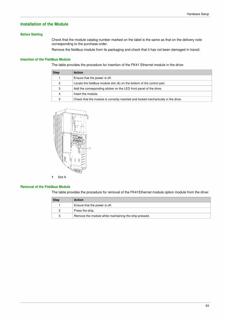
63
Hardware Setup
Installation of the Module
Before Starting
Check that the module catalog number marked on the label is the same as that on the delivery note
corresponding to the purchase order.
Remove the fieldbus module from its packaging and check that it has not been damaged in transit.
Insertion of the Fieldbus Module
The table provides the procedure for insertion of the FK41 Ethernet module in the drive:
Step Action
1 Ensure that the power is off.
2 Locate the fieldbus module slot (A) on the bottom of the control part.
3 Add the corresponding sticker on the LED front panel of the drive.
4 Insert the module.
5 Check that the module is correctly inserted and locked mechanically in the drive.
1 Slot A
Removal of the Fieldbus Module
The table provides the procedure for removal of the FK41Ethernet module option module from the drive:
Step Action
1 Ensure that the power is off.
2 Press the strip.
3 Remove the module while maintaining the strip pressed,
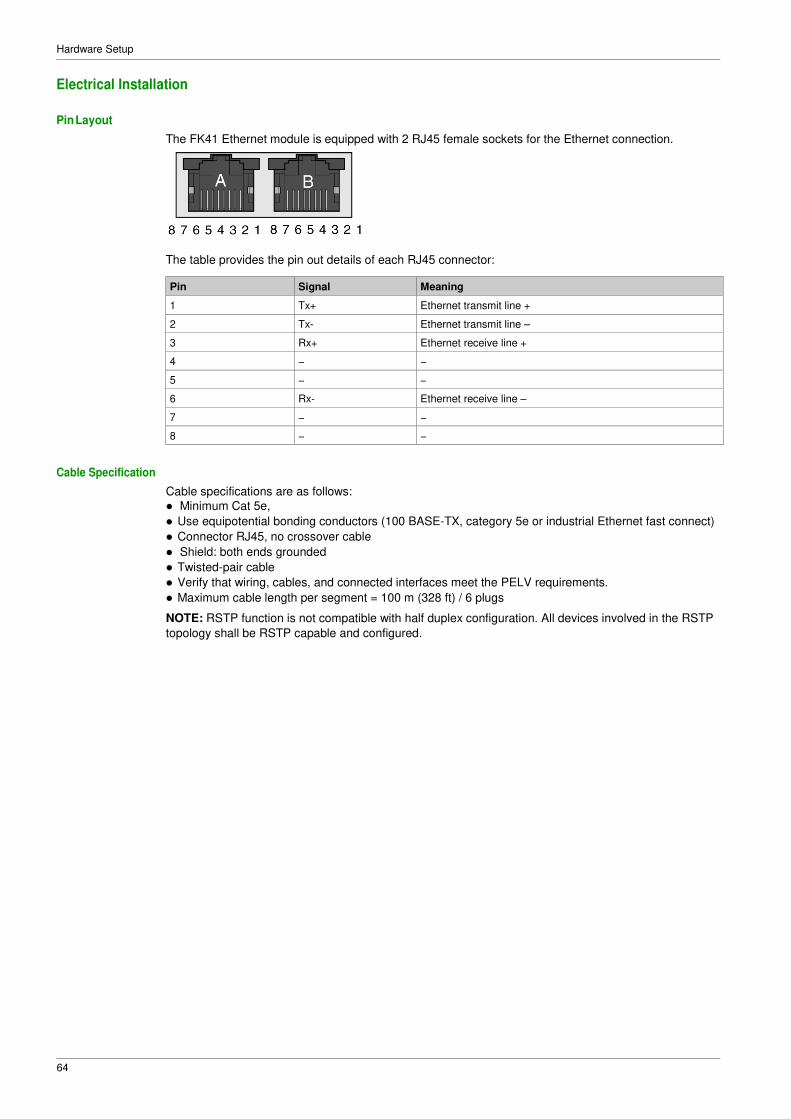
64
Hardware Setup
Electrical Installation
Pin Layout
The FK41 Ethernet module is equipped with 2 RJ45 female sockets for the Ethernet connection.
The table provides the pin out details of each RJ45 connector:
Pin Signal Meaning
1 Tx+ Ethernet transmit line +
2 Tx- Ethernet transmit line –
3 Rx+ Ethernet receive line +
4 − −
5 − −
6 Rx- Ethernet receive line –
7 − −
8 − −
Cable Specification
Cable specifications are as follows:
� Minimum Cat 5e,
� Use equipotential bonding conductors (100 BASE-TX, category 5e or industrial Ethernet fast connect)
� Connector RJ45, no crossover cable
� Shield: both ends grounded
� Twisted-pair cable
� Verify that wiring, cables, and connected interfaces meet the PELV requirements.
� Maximum cable length per segment = 100 m (328 ft) / 6 plugs
NOTE: RSTP function is not compatible with half duplex configuration. All devices involved in the RSTP
topology shall be RSTP capable and configured.

65
Hardware Setup
Cable Routing Practice
Installation Topology
The Ethernet adapter enables several wiring solutions:
� Daisy chain and/or Star topology
NOTE: In daisy chain topology, if one drive is turned off, an [Fieldbus Com Interrupt] CnF error is
trigged in the other drives connected to the same topology. To keep the integrity of Ethernet daisy chain
network when one or more drives are powered off, add an external permanent 24VDc supply to the
control block of the drive.
� Redundant ring topology with RSTP (with an RSTP switch)

66
Hardware Setup
� Redundant ring topology with RSTP (with a RSTP PLC)
� Redundant star topology with RSTP
The following figure shows the direct connection between the drive and PC.
67
Chapter 4 Software Setup
What Is in This Chapter?
This chapter contains the following sections:
Section Topic Page
4.1 Basic Settings 68
4.2 Additional Settings 79
4.3 Fast Device Replacement 88
4.4 Communication Profile 95
4.5 Embedded Webserver 112
4.6 Fieldbus Integration Using Unity Pro (M580) 119
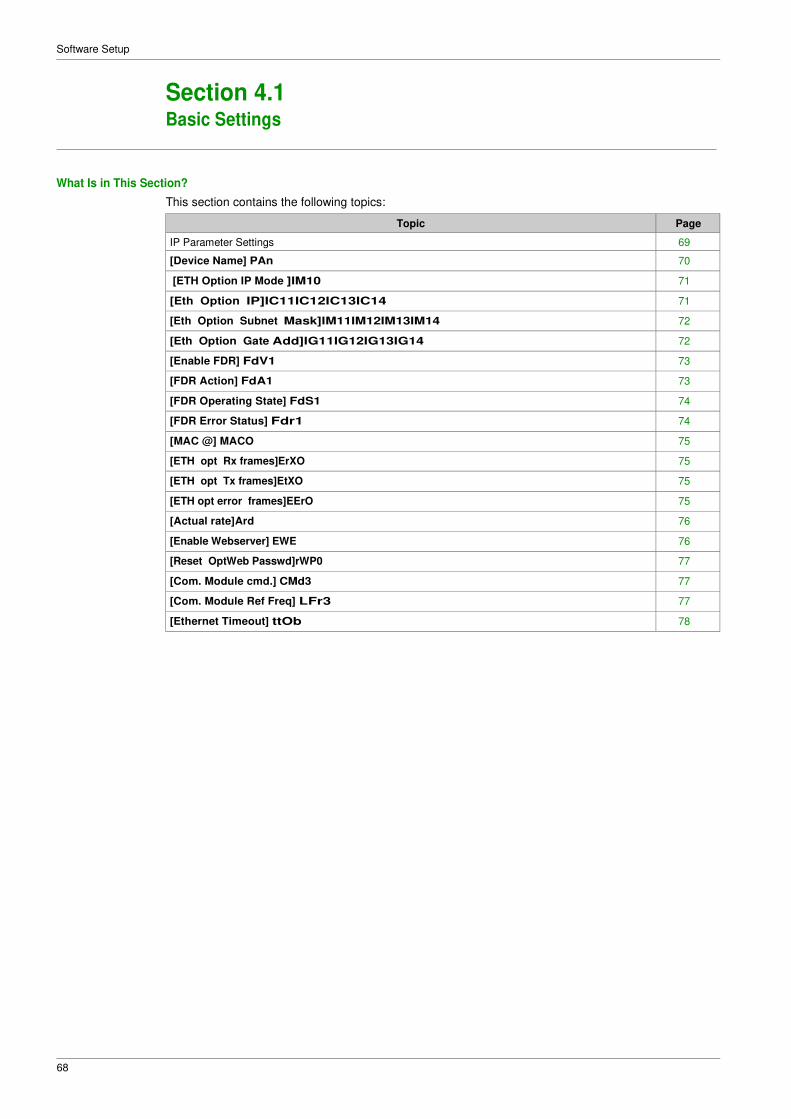
68
Software Setup
Section 4.1 Basic Settings
What Is in This Section?
This section contains the following topics:
Topic Page
IP Parameter Settings 69
[Device Name] PAn 70
[ETH Option IP Mode ]IM10 71
[Eth Option IP]IC11IC12IC13IC14 71
[Eth Option Subnet Mask]IM11IM12IM13IM14 72
[Eth Option Gate Add]IG11IG12IG13IG14 72
[Enable FDR] FdV1 73
[FDR Action] FdA1 73
[FDR Operating State] FdS1 74
[FDR Error Status] Fdr1 74
[MAC @] MACO 75
[ETH opt Rx frames]ErXO 75
[ETH opt Tx frames]EtXO 75
[ETH opt error frames]EErO 75
[Actual rate]Ard 76
[Enable Webserver] EWE 76
[Reset OptWeb Passwd]rWP0 77
[Com. Module cmd.] CMd3 77
[Com. Module Ref Freq] LFr3 77
[Ethernet Timeout] ttOb 78
69
Software Setup
IP Parameter Settings
Assigning IP Parameters
If not using IPV6 functionalities for DWPS, following parameters shall be configured:
� The drive IP address.
� The subnet mask.
� The gateway IP address.
These IP addresses can be entered using the display terminal, the embedded webserver, or the DTM-
based PC software.
They can be also provided by:
� A BOOTP server (correspondence between the MAC address and the IP addresses).
� Or a DHCP server (correspondence between device name [DEVICE NAME] PAn and the IP
addresses).
If an IP address other than 0.0.0.0 has been entered manually, assignment using a server is disabled.
Regardless of the type of IP address assignment, if the address is modified, then the IP address is effective
the next time the drive is turned on (control voltage if a separate power supply is being used).
Entering IP Parameters in the Display Terminal
In the [Communication] COM- , [Comm parameters] CMP- menu and [Eth Module Config]EtO-
submenu, enter the following IP addresses:
� [Eth Option IP] IC11 IC12 IC13 IC14
� [ETH Option Subnet Mask] IM11 IM12 IM13 IM14,
� [Eth Option Gate Add] IG11 IG12 IG13 IG14.
If this address is modified, the new IP address entered is displayed.
Configuring BOOTP
The BOOTP service is used to assign IP addresses based on the MAC address. The MAC address
consisting of 6 hexadecimal digits (MM-MM-MM-XX-XX-XX) must be entered in the BOOTP server. The
MAC address appears on the fieldbus adapter dedicated menu on the display terminal.
In the [Communication] COM- , [Comm parameters] CMP- menu and [Eth Module Config]EtO-
submenu:
� Leave the IP address [Eth Option IP]IC11IC12IC13IC14 at the value [0.0.0.0] 0000.
� Do not enable the FDR service.
Configuring DHCP
The DHCP service is used to assign IP addresses and FDR configuration file path based on the device name [DEVICE NAME] PAn.
The device name consisting of an alphanumeric string must be entered in both the DHCP server and the
drive.
In the [Communication] COM- , [Comm parameters] CMP- menu and [Eth Module Config]EtO-
submenu, enter the [DEVICE NAME] PAn

70
Software Setup
[Device Name] PAn
About This Parameter
This parameter is used set the device name.
Access
This parameter is accessible via [Communication] COM- , [Comm parameters] CMP- menu and [Eth
Module Config] EtO- submenu.
This is a read/write parameter
Possible Settings
The FDR (Fast Device Replacement) service is based on identification of the device by a Device Name. In
the case of the ER41 drive, this is represented by the [Device Name] PAn parameter. Verify that all the
network devices have different Device Name.
NOTE: The [Device Name] PAN is common for both Ethernet interfaces.

71
Software Setup
[ETH Option IP Mode ]IM10
About This Parameter
This parameter is used to select the IP address assignment method.
Access
This parameter is accessible via [Communication] COM- , [Comm parameters] CMP- menu and [Eth
Module Config] EtO- submenu.
This is a read/write parameter
The parameter number is 64450.
Possible Settings
The table presents the parameter settings:
Settings Code Value Description
[Fixed]
[BOOTP]
[DHCP]
MAnU 0
bOOt 1
dHCP 2
Manually set the IP address.
Automatically gets the IP address from the Bootp or DHCP server using the MAC
address.
Automatically gets the IP address from the DHCP server using the device name.
Factory setting: DHCP
[Eth Option IP]IC11IC12IC13IC14
About This Parameter
This parameter is used to set the IP address and can be edited only when the IP mode is set to fixed
address.
Access
This parameter is accessible via [Communication] COM- , [Comm parameters] CMP- menu and [Eth
Module Config]EtO-submenu.
This is a read/write parameter
The parameter number for IC11 is 64451
The parameter number for IC12 is 64452
The parameter number for IC13 is 64453
The parameter number for IC14 is 64454
Possible Settings
The table presents the parameter settings:
Settings Code Value Description
[139.160.069.241] 139 0...255 First byte of IP address.
1 0 0...255 Second byte of IP address.
0 9 0...255 Third byte of IP address.
241 0...255 Fourth byte of IP address.

72
Software Setup
[Eth Option Subnet Mask]IM11IM12IM13IM14
About This Parameter
This parameter is used to set the IP subnet mask and can be edited only when IP mode is set to fixed
address.
Access
This parameter is accessible via [Communication] COM- , [Comm parameters] CMP- menu and [Eth
Module Config] EtO- submenu.
This is a read/write parameter
The parameter number for IM11 is 64455
The parameter number for IM12 is 64456
The parameter number for IM13 is 64457
The parameter number for IM14 is 64458
Possible Settings
The table presents the parameter settings:
Settings Code Value Description
[255.255.254.0] 255 0...255 First byte of IP Mask.
255 0...255 Second byte of IP Mask.
254 0...255 Third byte of IP Mask.
0 0...255 Fourth byte of IP Mask.
[Eth Option Gate Add]IG11IG12IG13IG14
About This Parameter
This parameter is used to set the default gateway address and can be edited only IP mode is set to fixed
address.
Access
This parameter is accessible via [Communication] COM- , [Comm parameters] CMP- menu and [Eth
Module Config] EtO- submenu.
This is a read/write parameter
The parameter number for IG11 is 64459
The parameter number for IG12 is 64460
The parameter number for is IG13 64461
The parameter number for is IG14 64462
Possible Settings
The table presents the parameter settings:
Settings Code Value Description
[0.0.0.0] 0 0...255 First byte of IP gateway.
0 0...255 Second byte of IP gateway
0 0...255 Third byte of IP gateway
0 0...255 Fourth byte of IP gateway

73
Software Setup
[Enable FDR] FdV1
About This Parameter
This parameter is used to enable or disable the FDR service.
Access
This parameter is accessible via [Communication] CoM-, [Comm parameters] CMP- menu, [Eth
Module Config] EtO- submenu and [Fast Device Replacement] Fdr- submenu.
This is a read/write parameter.
The parameter number is 64445
This parameter can be accessed if [ETH Option IP Mode] IM10 is set to [DHCP] dHCP
Possible Settings
The table presents the parameter settings:
Settings Code Value Description
[No]
[Yes]
nO 0
YES 1
No: FDR service disabled
Yes: FDR service enabled
Factory setting: No
[FDR Action] FdA1
About This Parameter
This parameter is used to select the FDR action that needs to be performed.
Access
This parameter is accessible via [Communication] CoM-, [Comm parameters] CMP- menu, [Eth
Module Config] EtO- submenu and [Fast Device Replacement] Fdr- submenu.
This is a read/write parameter.
The parameter number is 64444
This parameter can be accessed if [ETH Option IP Mode] IM10 is set to [DHCP] dHCP
Possible Settings
The table presents the parameter settings:
Settings Code Value Description
[NOT ACTIVE]
[SAVE]
[REST]
IdLE 0
SAVE 1
rESt 2
Not active: No FDR action
Save: FDR save command
Restore: FDR restore command

74
Software Setup
[FDR Operating State] FdS1
About This Parameter
This parameter is used to display the FDR operating state.
Access
This parameter is accessible via [Communication] CoM-, [Comm parameters] CMP- menu, [Eth
Module Config] EtO- submenu and [Fast Device Replacement] Fdr- submenu.
This is a read-only parameter.
The parameter number is 64443
This parameter can be accessed if [ETH Option IP Mode] IM10 is set to [DHCP] dHCP
Possible Settings
The table presents the parameter settings:
Settings Code Value Description
[Initialization] InIt 0 INIT: Initialization
[Not Active] IdLE 1 IDLE: Function not active
[Operational] OPE 2 OPE: Operational
[Ready] rdY 4 RDY: Ready
[IP Configuration] IPC 5 IPC: IP configuration
[Not Configured] UnCF 7 UNCF: Function not configured
[Reading Configuration] GEt 8 GET: Download the current configuration
[Writing Configuration] SEt 9 SET: Save the current configuration
[Applying Configuration] APP 10 APP: Applying the configuration to the drive
[FDR Error Status] Fdr1
About This Parameter
This parameter is used to display the FDR error status.
Access
This parameter is accessible via [Communication] CoM-, [Comm parameters] CMP- menu, [Eth
Module Config] EtO- submenu and [Fast Device Replacement] Fdr- submenu.
This is a read-only parameter.
The parameter number is 64442
This parameter can be accessed if [ETH Option IP Mode] IM10 is set to [DHCP] dHCP
Possible Settings
The table presents the parameter settings:
Settings Code Value Description
[No Error] nO 0 NO: No error
[Service Timeout] tOUt 1 TOUT: Server timeout
[Server No File] SnF 2 SNF: No file on server
[Server Corrupt File] CrPt 3 CRPT: Corrupted file on server
[Server Empty File] EPtY 4 EPTY: Empty file on server
[Drive Invalid File] HInV 5 HINV: Invalid file on drive
[CRC Error] CrC 6 CRC: CRC error
[Version Incompatibility] VrM 7 VRM: Version incompatibility between drive and file
[Drive No File] HnF 9 HNF: No file on drive
[Server Reading Size] SIZE 10 SIZE: File size reading error on server
[Drive Opening File] OPEn 11 OPEN: Drive cannot open the file
[Drive Reading File] rEAD 12 READ: Drive cannot read the file
[Incompatibility] SCnt 13 SCNT: File incompatibility
[Drive Invalid Name] nInV 14 NINV: Drive name is invalid
[Server Incorrect File Size] FSIZ 15 FSIZ: Incorrect file size on server
[Drive Writing File] HWF 16 HWF: Drive cannot write the file
[Server Writing File] SWF 17 SWF: Server cannot write the file
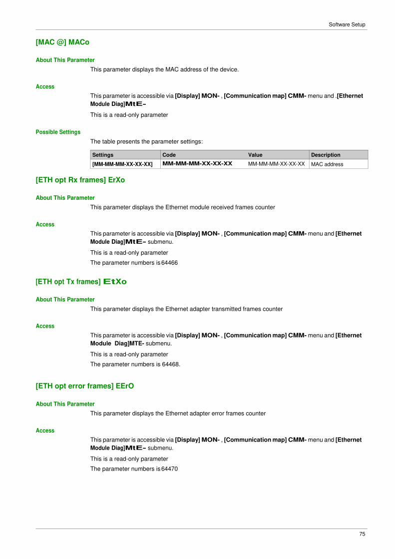
75
Software Setup
[MAC @] MACo
About This Parameter
This parameter displays the MAC address of the device.
Access
This parameter is accessible via [Display] MON- , [Communication map] CMM- menu and .[Ethernet
Module Diag]MtE-
This is a read-only parameter
Possible Settings
The table presents the parameter settings:
Settings Code Value Description
[MM-MM-MM-XX-XX-XX] MM-MM-MM-XX-XX-XX MM-MM-MM-XX-XX-XX MAC address
[ETH opt Rx frames] ErXo
About This Parameter
This parameter displays the Ethernet module received frames counter
Access
This parameter is accessible via [Display] MON- , [Communication map] CMM- menu and [Ethernet
Module Diag]MtE- submenu.
This is a read-only parameter
The parameter numbers is 64466
[ETH opt Tx frames] EtXo
About This Parameter
This parameter displays the Ethernet adapter transmitted frames counter
Access
This parameter is accessible via [Display] MON- , [Communication map] CMM- menu and [Ethernet
Module Diag]MTE- submenu.
This is a read-only parameter
The parameter numbers is 64468.
[ETH opt error frames] EErO
About This Parameter
This parameter displays the Ethernet adapter error frames counter
Access
This parameter is accessible via [Display] MON- , [Communication map] CMM- menu and [Ethernet
Module Diag]MtE- submenu.
This is a read-only parameter
The parameter numbers is 64470
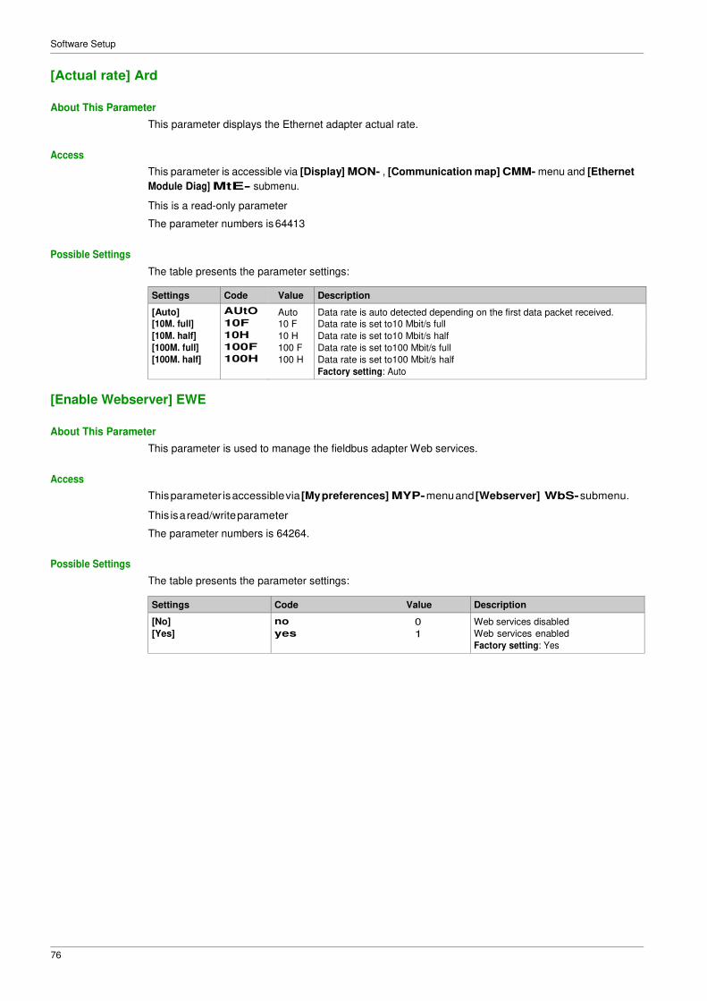
76
Software Setup
[Actual rate] Ard
About This Parameter
This parameter displays the Ethernet adapter actual rate.
Access
This parameter is accessible via [Display] MON- , [Communication map] CMM- menu and [Ethernet
Module Diag] MtE- submenu.
This is a read-only parameter
The parameter numbers is 64413
Possible Settings
The table presents the parameter settings:
Settings Code Value Description
[Auto] AUtO Auto Data rate is auto detected depending on the first data packet received. [10M. full] 10F 10 F Data rate is set to10 Mbit/s full
[10M. half] 10H 10 H Data rate is set to10 Mbit/s half
[100M. full] 100F 100 F Data rate is set to100 Mbit/s full
[100M. half] 100H 100 H Data rate is set to100 Mbit/s half
Factory setting: Auto
[Enable Webserver] EWE
About This Parameter
This parameter is used to manage the fieldbus adapter Web services.
Access
This parameter is accessible via [My preferences] MYP- menu and [Webserver] WbS- submenu.
This is a read/write parameter
The parameter numbers is 64264.
Possible Settings
The table presents the parameter settings:
Settings Code Value Description
[No]
[Yes]
no 0
yes 1
Web services disabled
Web services enabled
Factory setting: Yes

77
Software Setup
[Reset OptWeb Passwd] rWP0
About This Parameter
This parameter is used to manage the set to factory value the Ethernet webserver settings, including the
password.
Access
This parameter is accessible via [My preferences] MYP- menu and [Webserver] WbS- submenu.
This is a read/write parameter
Possible Settings
The table presents the parameter settings:
Settings Code Value Description
[No]
[Yes]
no 0
yes 1
Reset of the adapter webserver password not requested
Reset of the adapter webserver password requested
NOTE: � The parameter is set to [No] when the operation is done
� The webserver must be refreshed in browser to take into account the
new password.
[Com. Module cmd.] CMd3
About This Parameter
This parameter displays the command word built with Ethernet module source (same as CMD).
Access
This parameter is accessible via [Display] MON- , [Communication map] CMM- menu and [Command
word image] CW|- submenu.
This is a read-only parameter
The parameter numbers is 8513
[Com. Module Ref Freq] LFr3
About This Parameter
This parameter displays the reference frequency built with Ethernet module source (same as LFr).
Access
This parameter is accessible via [Display] MON- , [Communication map] CMM- menu and [Command
word image] CW| - submenu.
This is a read-only parameter
The parameter numbers is 8523

78
Software Setup
[Ethernet Timeout] ttOb
About This Parameter
This parameter is used to set the Ethernet timeout.
Access
This parameter is accessible via fieldbus using the Modbus address.
This is a read/write parameter
The parameter number is 64415.
Possible Settings
The table presents the parameter settings:
Settings Description
0.1...30 sec Factory setting: 10 sec

79
Software Setup
Section 4.2 Additional Settings
What Is in This Section?
This section contains the following topics:
Topic Page
FDR Settings 80
RSTP Settings 81
Configuring I/O Scanning 83
DNS Settings 84
SNTP Settings 85
SNMP Settings 86

80
Software Setup
FDR Settings
Access
The parameters are accessible via the webserver or the DTM-based PC software
FDR Configuration
The following figure shows FDR settings via webserver:
The table presents the FDR Configuration settings:
Parameter Description Settings
FDR Activation This parameter is used to enable or
disable the FDR service
NOTE: You can enable FDR only if the
IP assignment mode selected is
DHCP.
Enabled: FDR service enabled
Disabled: FDR service disabled.
Factory setting: Enabled
Control Configuration This parameter is used to select the
server or local configuration.
Served: Transfers the configuration file
from server to drive at power-up.
Stored: uses the configuration stored in
the drive at power-up.
Factory setting: served
Automatic Syncho Cycle (x 10 Sec) Allows you to select the interval for
periodic synchronization of the drive
with the FDR server.
NOTE: You can configure automatic
Synchro cycle only if Synchronization
mode check box is selected.
10...655350 sec
Factory setting: 2560 sec

81
Software Setup
RSTP Settings
Access
The parameters are accessible via the DTM-based PC software.
Bridge Settings
The following figure shows the bridge settings using the DTM:
The table presents the Bridge configuration
Parameters Description Settings
Enable RSTP Allows you to enable or disable the RSTP To enable RSTP, select the Enable
RSTP check box.
Status Allows you to enable or disable the RSTP
bridge.
Enabled: Enables the use of Rapid
Spanning-Tree Protocol (RSTP).
Disabled:Disables the use of Rapid
Spanning-Tree Protocol (RSTP)
Bridge Priority The bridge priority is used to control which
bridge is elected as the root bridge.
Bridge with the smallest (lowest) bridge ID is
elected as the root bridge. Bridge ID consists of
the configurable priority and the MAC address
of the bridge.
To compare 2 bridge ids, bridge priorities are
compared first. If the bridge priorities are equal,
then the MAC addresses are compared.
The bridge priority can be set only in
increments of 4096
0
4096
8192
12288
16384
20480
24576
28672
32768
36864
40960
45056
49152
53248
57344
61440
0 hex
1000 hex
2000 hex
3000 hex
4000 hex
5000 hex
6000 hex
7000 hex
8000 hex
9000 hex
A000 hex
B000 hex
C000 hex
D000 hex
E000 hex
F000 hex
Hello Time(S) The hello time parameter corresponds to the
time interval at which the root bridge transmits
configuration Bridge Protocol Data Units
(BPDU)s.
1...10 sec
Max age time (6-40 s The maximum age time correspond to the
maximum expected arrival time of hello
BPDUs. If the timer expires, the bridge detects
acommunication interruption to the root bridge
and initiates a topology convergence.The
maximum age timer should be longer than the
configured hello time.
6...40 sec
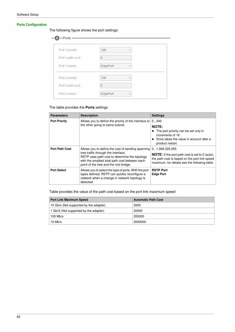
82
Software Setup
Ports Configuration
The following figure shows the port settings:
The table provides the Ports settings
Parameters Description Settings
Port Priority Allows you to define the priority of the interface to
the other going to same subnet.
0...240
NOTE: � The port priority can be set only in
increments of 16
� Drive takes the value in account after a
product restart.
Port Path Cost Allows you to define the cost of sending spanning
tree traffic through the interface.
RSTP uses path cost to determine the topology
with the smallest total path cost between each
point of the tree and the root bridge.
0...1,569,325,055
NOTE: If the port path cost is set to 0 (auto),
the path cost is based on the port link speed
maximum, for details see the following table.
Port Select Allows you to select the type of ports. With the port
types defined, RSTP can quickly reconfigure a
network when a change in network topology is
detected.
RSTP Port
Edge Port
Table provides the value of the path cost based on the port link maximum speed
Port Link Maximum Speed Automatic Path Cost
10 Gb/s (Not supported by the adapter) 2000
1 Gb/S (Not supported by the adapter) 20000
100 Mb/s 200000
10 Mb/s 2000000

83
Software Setup
Configuring I/O Scanning
Description
The drive I/O scanning service can be enabled or disabled with the DTM-based PC software.
It is not possible to modify the assignment of the I/O scanning periodic variables using the display terminal.
To configure I/O scanning, use the DTM-based PC software.

84
Software Setup
DNS Settings
Description
The Domain Name System (DNS) is a distributed naming system for devices connected to the network.
It translates domain names to IP addresses for locating the devices easily on the network.
DNS Configuration
The DNS configuration can be done using the DTM-based PC software.
The following figure shows the DNS configuration window:
The table presents the DNS Configuration settings:
Item Description
1 Obtain DNS Server address automatically: When checked, the function is enabled and allows getting
automatically the IP address from the DNS server.
2 Preferred DNS server: Enter the IP address of the preferred DNS server.
3 Alternate DNS server: Enter the IP address of the alternate DNS server.
NOTE: The alternate IP address is used only if the first server is unavailable.
NOTE: The changes must be applied to the module configuration by clicking the button.
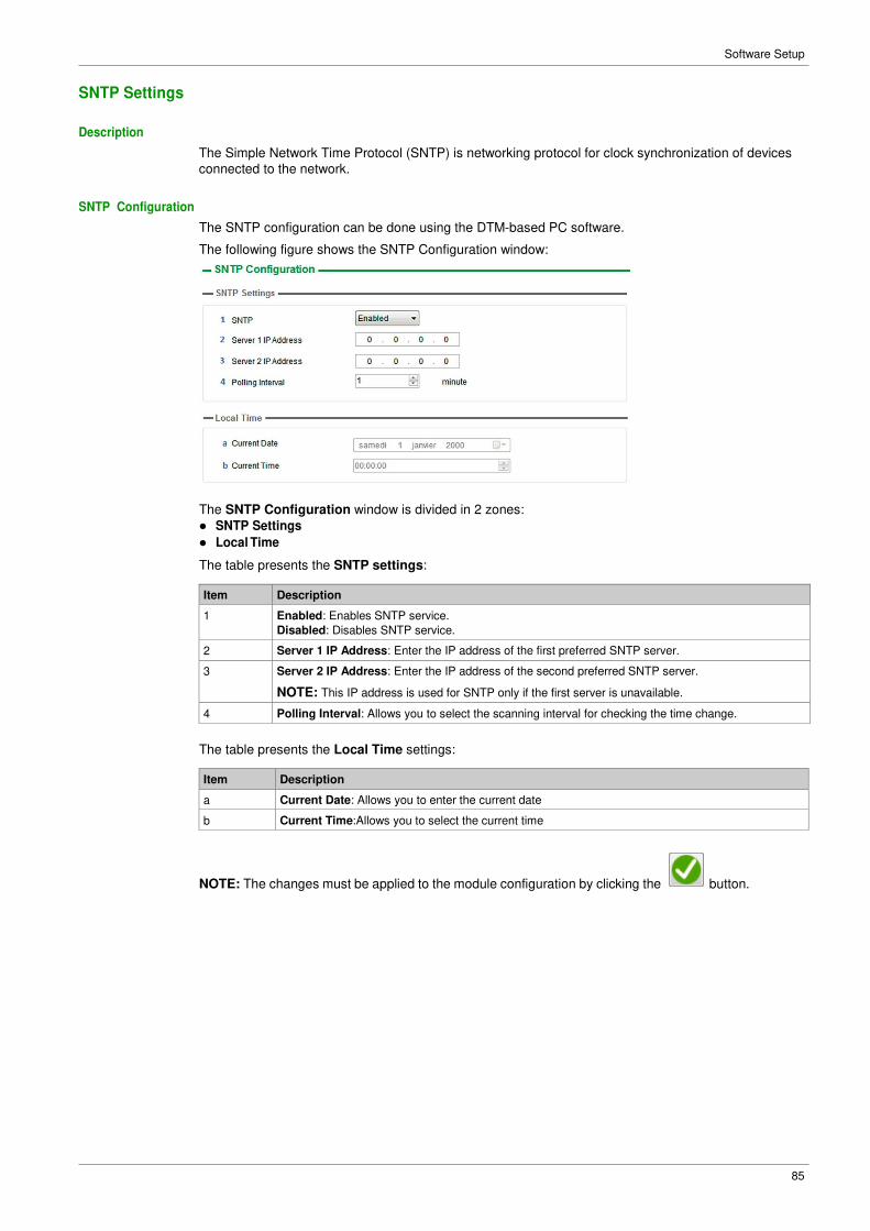
85
Software Setup
SNTP Settings
Description
The Simple Network Time Protocol (SNTP) is networking protocol for clock synchronization of devices
connected to the network.
SNTP Configuration
The SNTP configuration can be done using the DTM-based PC software.
The following figure shows the SNTP Configuration window:
The SNTP Configuration window is divided in 2 zones:
� SNTP Settings
� Local Time
The table presents the SNTP settings:
Item Description
1 Enabled: Enables SNTP service.
Disabled: Disables SNTP service.
2 Server 1 IP Address: Enter the IP address of the first preferred SNTP server.
3 Server 2 IP Address: Enter the IP address of the second preferred SNTP server.
NOTE: This IP address is used for SNTP only if the first server is unavailable.
4 Polling Interval: Allows you to select the scanning interval for checking the time change.
The table presents the Local Time settings:
Item Description
a Current Date: Allows you to enter the current date
b Current Time:Allows you to select the current time
NOTE: The changes must be applied to the module configuration by clicking the button.

86
Software Setup
SNMP Settings
Description
Simple Network Management Protocol (SNMP) is an internet-standard protocol used to manage devices
on IP networks.
It is used for collecting and organizing information about the devices on the network.
SNMP Configuration
The SNMP configuration can be done using the DTM-based PC software.
The following figure shows the SNTP Configuration window:
The SNMP Configuration window is divided in 4 zones:
� Manager’s IP Address
� Agent
� Community Names
� Enabled Traps
Manager's IP Address
SNMP manager is a central system used for monitoring and controlling the SNMP agents.
The table presents Manager’s IP Address settings:
Item Description
1a Manager 1: SNMP manager is a central system, which is used for monitoring and controlling the
SNMP agents.
2a Manager 2: Enter the IP address of SNMP manager 2.
Agents
Agents are the devices which are connected to the network. The SNMP manager monitors these devices.
The table presents the Agents settings:
Item Description
1b System Name: Enter the system name used by the drive.
2b System Location: Enter the system location of the drive.
3b System Contact:Contact point to get the information about the system.
Enter the system contact of the drive.
BLEMO

87
Software Setup
Community Names
Community names are used to identify the commands that can be performed by an SNMP manager on a
device.
The table presents the Community Names settings:
Item Description
1c Get: Requests send from manager to agent to retrieve data.
2c Set: Requests send from manager to agent to change data.
3c Trap: Requests send from manager to agent to find the available data.
Enabled Traps
Traps are used to inform the SNMP manager of specific events occurring on device.
The table presents the Enabled Traps settings:
Item Description
1d Cold Start: The agent reinitialized its configuration tables.
2d Link Down Trap: A network interface card (NIC) on agent reinitializes.
3d Link Up Trap: A network interface card (NIC) on agent stops responding.
4d Authentication Failure Trap: SNMP agent gets a request from an unrecognized community name.

88
Software Setup
Section 4.3 Fast Device Replacement
What Is in This Section?
This section contains the following topics:
Topic Page
Presentation 89
Startup Detailed Behavior 90
FDR Operation Behavior 91
Local Configuration 92
Downloaded Configuration 93

89
Software Setup
Presentation
FDR Service
The FDR (Fast Device Replacement) service is used to simplify the maintenance of drives connected to
an Ethernet network. In the event of a drive not working correctly, this service automatically reconfigures
its replacement.
The new drive (FDR client) retrieves:
� Its IP addresses and the FDR file path from a DHCP server
� The FDR file from an FTP server if the drive is not configured in local configuration
In practice, the DHCP server and the FTP server are the same device (PAC M580, M340 PLC, or
dedicated PCs).
The FDR file contains:
� The Ethernet parameters (configuration of I/O scanning, FDR, and so on)
� The drive parameters (drive, functions, application, and so on)
The FDR service is based on identification of the device by a Device Name. In the case of the drive, this
is represented by the [DEVICE NAME] PAn parameter.
The configuration of the FDR service is accessible via embedded webserver or DTM-based software or
Graphic Display Terminal.
NOTE: Check that all the network devices have different Device Name.
The FDR server controls duplication of Device Name (it does not assign an IP address that has already
been assigned and is active).
If the same IP address is supplied on 2 devices, the second should trigger an IP address duplication (network management detected error which triggers an [Fieldbus Error] EPF2 by default).
If the FDR service has been enabled, the Ethernet adapter attempts to restore its IP addresses on each
power-up. Each time the procedure has detected error, the Ethernet adapter reiterates its FDR requests
(DHCP).
After assigning the Ethernet adapter IP addresses, if the configuration is not downloaded successfully, the Ethernet adapter triggers a [FDR2 Error] FDR2.

90
Software Setup
Startup Detailed Behavior
Presentation

91
Software Setup
FDR Operation Behavior
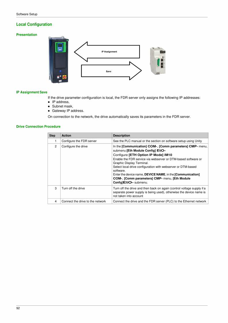
92
Software Setup
Local Configuration
Presentation
IP Assignment Save
If the drive parameter configuration is local, the FDR server only assigns the following IP addresses:
� IP address,
� Subnet mask,
� Gateway IP address.
On connection to the network, the drive automatically saves its parameters in the FDR server.
Drive Connection Procedure
Step Action Description
1 Configure the FDR server See the PLC manual or the section on software setup using Unity
2 Configure the drive In the [Communication] COM-, [Comm parameters] CMP- menu,
submenu:[Eth Module Config] EtO-
Configure [ETH Option IP Mode] iM10
Enable the FDR service via webserver or DTM-based software or
Graphic Display Terminal.
Select local drive configuration with webserver or DTM-based
software.
Enter the device name, DEVICE NAME, in the [Communication]
COM-, [Comm parameters] CMP- menu, [Eth Module
Config]EtO- submenu.
3 Turn off the drive Turn off the drive and then back on again (control voltage supply if a
separate power supply is being used), otherwise the device name is
not taken into account
4 Connect the drive to the network Connect the drive and the FDR server (PLC) to the Ethernet network

93
Software Setup
Downloaded Configuration
Presentation
IP Assignment Save
If the drive parameter configuration has been downloaded, the FDR server assigns the following
addresses:
� IP address,
� Subnet mask,
� Gateway IP address,
� FDR server IP address.
Periodic Saving
Periodic saving of the drive configuration can be configured on the FDR server in either local configuration
or downloaded configuration mode
Using the embedded webserver or the DTM-based software:
� Set FDR synchronization to automatic mode
� Set the synchronization cycle time
NOTE: Saving too often overburden the fieldbus and adversely affects its performance (factory setting:
2.560 s.).
Limitations
The FDR service is able to store the current configuration of the drive, but does not provide the possibility
to store multi-parameters configurations.

94
Software Setup
Drive Parameters (Configuration)
In the procedure described below, the configuration file is transferred to the FDR server, via the Ethernet
network, using a manual save command.
Step Action Description
1 Configure the drive In the [Communication] COM-, [Comm parameters] CMP-
menu, [Eth Module Config]EtO- submenu:
� Leave the IP address [ETH Option
IP]IC11IC12IC13IC14 at the value [0.0.0.0] 0000
Using the embedded webserver or the DTM-based software:
� Set FDR synchronization to manual mode.
� Before the first connection, select local drive configuration. The
drive needs first to push the configuration to the server.
Enter the device name, DEVICE NAME, in the [Communication]
COM-, [Comm parameters] CMP- menu, [Eth Module
Config]EtO- submenu.
2 Turn off the drive Turn off the drive and then back on again (control voltage if a
separate power supply is being used), otherwise the device name is
not taken into account
3 Connect the drive to the fieldbus Connect the drive and the FDR server (PLC) to the Ethernet
fieldbus.
4 Configure the FDR server (see the
PLC manual)
The server downloads the IP addresses to the Ethernet adapter.
Check that the operation has proceeded correctly: you can also
check, in the [Communication] COM-, [Comm parameters]
CMP- menu, [Eth Module Config]EtO- submenu. Whether the
[Eth Option IP]IC11IC12IC13IC14 [ETH Option Subnet
Msk] iM11iM12iM13iM14 and [ETH Option Gate Add]
iG11iG12iG13iG14 parameters have values other than
[0.0.0.0] 0000
5 Supply the FDR server with the
configuration file
Using the embedded webserver or the DTM-based software
� Specify that the drive configuration is downloaded from the FDR
server on each power-up
� Send a save command to the FDR server.
6 Check that the system is operational If the save operation has not been successful, the adapter detects a
communication error which, in factory settings mode, triggers a
[FDR2 Error]Fdr2
Replacing a Drive
For replacing a drive, it is necessary to follow the procedure below:
Step Action Action
1 Configure the drive In the [Communication] COM-, [Comm parameters] CMP- menu,
[Eth Module Config]EtO- submenu:
� Leave the IP address [Eth Option
IP]IC11IC12IC13IC14 at the value [0.0.0.0] 0000
Using the embedded webserver or the DTM-based software:
� Set FDR synchronization to manual mode.
� Before the first connection, select served drive configuration. The
drive needs first to transfer the configuration from the server.
Enter the device name, DEVICE NAME, in the [Communication]
COM-, [Comm parameters] CMP- menu, [Eth Module
Config]EtO- submenu.
2 Turn off the drive Turn off the drive and then back on again (control voltage if a
separate power supply is being used), otherwise the device name is
not taken into account
3 Connect the drive to the fieldbus Connect the drive and the FDR server (PLC) to the Ethernet fieldbus
4 Check that the drive is operational Check that the operation has proceeded correctly.
If downloading has not been possible after a period of 2 min following
assignment of the IP addresses, the adapter detects a
communication error which, in factory settings mode, triggers an
[FDR2 Error]Fdr2

95
Software Setup
Section 4.4 Communication Profile
What Is in This Section?
This section contains the following topics:
Topic Page
Definition of a Profile 96
Functional Profiles Supported by the Drive 97
Functional Description 98
CIA402 Operating State Diagram 99
Description of Operating States 100
Summary 102
Cmd Register CMd 103
Stop Commands 104
Assigning Control Word Bits 104
[CIA402 State Reg] EtA 105
Starting Sequence 106
Sequence for a Drive Powered by the Power Stage Supply 107
Sequence for a Drive with Separate Control Stage 108
Sequence for a Drive with Mains Contactor Control 111
96
Software Setup
Definition of a Profile
Types of Profiles
There are 3 types of profile:
� Communication profiles
� Functional profiles
� Application profiles
Communication Profile
A communication profile describes the characteristics of a bus or network:
� Cables
� Connectors
� Electrical characteristics
� Access protocol
� Addressing system
� Periodic exchange service
� Messaging service
� ...
A communication profile is unique to a type of fieldbus (such as Modbus, PROFIBUS DP, and so on) and
is used by different types of devices.
Functional Profile
A functional profile describes the behavior of a type of device:
� Functions
� Parameters (such as name, format, unit, type, and so on.)
� Periodic I/O variables
� State chart
� ...
A functional profile is common to all members of a device family (such as variable speed drives, encoders,
I/O modules, displays, and so on).
They can feature common or similar parts. The standardized (IEC 61800-7) functional profiles of variable
speed drives are: � CiA402
� PROFIDRIVE
� CIP AC Drive
CiA402 device profile for drives and motion control represents the next stage of this standard development
and is now part of the IEC 61800-7 standard.
Application Profile
Application profile defines the services to be provided by the devices on a machine. For example, CiA DSP
417-2 V 1.01 part 2: CANopen application profile for lift control systems - virtual device definitions.
Interchangeability
The aim of communication and functional profiles is to achieve interchangeability of the devices connected
via the fieldbus.

97
Software Setup
Functional Profiles Supported by the Drive
I/O Profile
Using the I/O profile simplifies PLC programming.
The I/O profile mirrors the use of the terminal strip for control by utilizing 1 bit to control a function.
The I/O profile for the drive can also be used when controlling via a fieldbus.The drive starts up as soon as
the run command is sent.15 bits of the control word (bits 1...15) can be assigned to a specific function.
This profile can be developed for simultaneous control of the drive via:
� The terminals
� The Modbus control word
� The CANopen control word
� Ethernet Modbus TCP embedded
� The fieldbus module control word
The I/O profile is supported by the drive itself and therefore in turn by all the communication ports
(integrated Modbus, and fieldbus modules).
CiA402 Profile
The drive only starts up following a command sequence.
The control word is standardized.
5 bits of the control word (bits 11...15) can be assigned to a function.
The CiA402 profile is supported by the drive itself and therefore by all the communication ports (integrated
Modbus, CANopen, and fieldbus modules).
The drive supports the velocity mode of CiA402 profile.
In the CiA402 profile, there are two modes that are specific to the drive and characterize commands and
references value management:
� Separate [Separate] SEP
� Not separate [Not separ.] SIM,

98
Software Setup
Functional Description
Introduction
Drive operation involves two main functions, which are illustrated in the diagrams below.
CiA402
ER41 Drive
The main parameters are shown with their CiA402 name and their CiA402/Drivecom index (the values in
brackets are the CANopen addresses of the parameter).
The following figure shows the control diagram for drive operation:
Simplified diagram for speed control in Velocity mode:
These diagrams translate as follows for the ER41 drive.
The following figure shows the control diagram for drive operation:
Simplified diagram for speed control in Velocity mode:

99
Software Setup
CIA402 Operating State Diagram
State Diagram
After switching on and when an operating mode is started, the product goes through a number of operating
states.
The state diagram (state machine) shows the relationships between the operating states and the state
transitions. The operating states are internally monitored and influenced by monitoring functions.
The following figure shows the CIA402 state diagram:
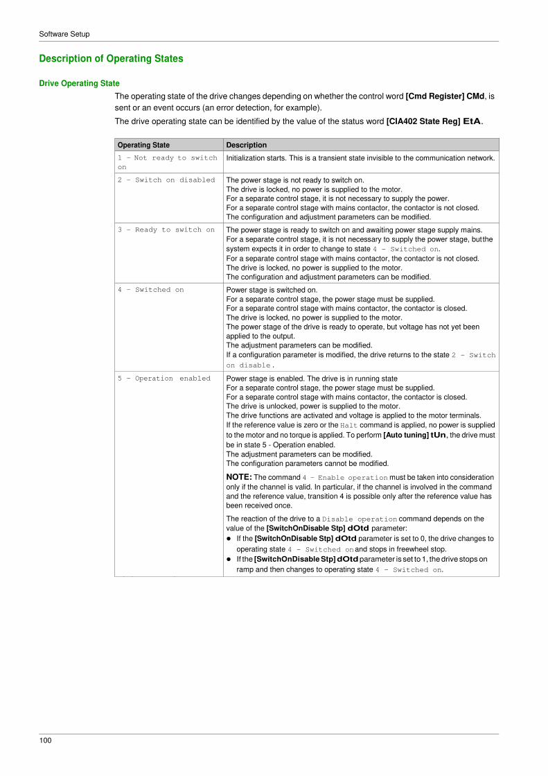
Software Setup
100
Description of Operating States
Drive Operating State
The operating state of the drive changes depending on whether the control word [Cmd Register] CMd, is
sent or an event occurs (an error detection, for example).
The drive operating state can be identified by the value of the status word [CIA402 State Reg] EtA.
Operating State Description
1 -
on
Not ready to switch Initialization starts. This is a transient state invisible to the communication network.
2 - Switch on disabled The power stage is not ready to switch on.
The drive is locked, no power is supplied to the motor.
For a separate control stage, it is not necessary to supply the power.
For a separate control stage with mains contactor, the contactor is not closed.
The configuration and adjustment parameters can be modified.
3 - Ready to switch on The power stage is ready to switch on and awaiting power stage supply mains.
For a separate control stage, it is not necessary to supply the power stage, but the
system expects it in order to change to state 4 - Switched on.
For a separate control stage with mains contactor, the contactor is not closed.
The drive is locked, no power is supplied to the motor.
The configuration and adjustment parameters can be modified.
4 - Switched on Power stage is switched on.
For a separate control stage, the power stage must be supplied.
For a separate control stage with mains contactor, the contactor is closed.
The drive is locked, no power is supplied to the motor.
The power stage of the drive is ready to operate, but voltage has not yet been
applied to the output.
The adjustment parameters can be modified.
If a configuration parameter is modified, the drive returns to the state 2 - Switch
on disable .
5 - Operation enabled Power stage is enabled. The drive is in running state
For a separate control stage, the power stage must be supplied.
For a separate control stage with mains contactor, the contactor is closed.
The drive is unlocked, power is supplied to the motor.
The drive functions are activated and voltage is applied to the motor terminals.
If the reference value is zero or the Halt command is applied, no power is supplied
to the motor and no torque is applied. To perform [Auto tuning] tUn, the drive must
be in state 5 - Operation enabled.
The adjustment parameters can be modified.
The configuration parameters cannot be modified.
NOTE: The command 4 - Enable operation must be taken into consideration
only if the channel is valid. In particular, if the channel is involved in the command
and the reference value, transition 4 is possible only after the reference value has
been received once.
The reaction of the drive to a Disable operation command depends on the
value of the [SwitchOnDisable Stp] dOtd parameter:
� If the [SwitchOnDisable Stp] dOtd parameter is set to 0, the drive changes to
operating state 4 - Switched on and stops in freewheel stop.
� If the [SwitchOnDisable Stp] dOtd parameter is set to 1, the drive stops on
ramp and then changes to operating state 4 - Switched on.
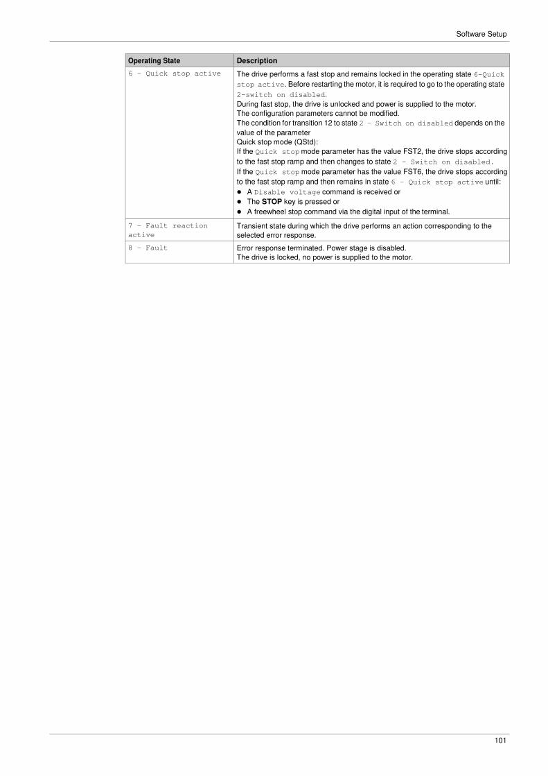
Software Setup
101
Operating State Description
6 - Quick stop active The drive performs a fast stop and remains locked in the operating state 6-Quick
stop active. Before restarting the motor, it is required to go to the operating state
2-switch on disabled.
During fast stop, the drive is unlocked and power is supplied to the motor.
The configuration parameters cannot be modified.
The condition for transition 12 to state 2 - Switch on disabled depends on the
value of the parameter
Quick stop mode (QStd):
If the Quick stop mode parameter has the value FST2, the drive stops according
to the fast stop ramp and then changes to state 2 - Switch on disabled .
If the Quick stop mode parameter has the value FST6, the drive stops according
to the fast stop ramp and then remains in state 6 - Quick stop active until:
� A Disable voltage command is received or
� The STOP key is pressed or
� A freewheel stop command via the digital input of the terminal.
7 - Fault reaction
active
Transient state during which the drive performs an action corresponding to the
selected error response.
8 - Fault Error response terminated. Power stage is disabled.
The drive is locked, no power is supplied to the motor.
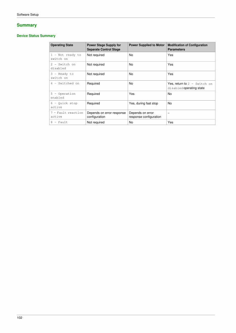
Software Setup
102
Summary
Device Status Summary
Operating State Power Stage Supply for
Separate Control Stage
Power Supplied to Motor Modification of Configuration
Parameters
1 - Not ready to
switch on
Not required No Yes
2 - Switch on
disabled
Not required No Yes
3 - Ready to
switch on
Not required No Yes
4 - Switched on Required No Yes, return to 2 - Switch on
disabled operating state
5 - Operation
enabled
Required Yes No
6 - Quick stop
active
Required Yes, during fast stop No
7 - Fault reaction
active
Depends on error response
configuration
Depends on error
response configuration
−
8 - Fault Not required No Yes

Software Setup
103
Cmd Register CMd
Bit Mapping of the Control Word
Bit 7 Bit 6 Bit 5 Bit 4 Bit 3 Bit 2 Bit 1 Bit 0
Fault reset Reserved
(=0)
Reserved
(=0)
Reserved
(=0)
Enable
operation
Quick stop Enable
voltage
Switch on
0 to 1
transition =
Error is
reset (after
cause of
error is no
longer
active)
1 = Run
command
0 = Quick
stop active
Authorization
to supply AC
power
Mains
contactor
control
Bit 15 Bit 14 Bit 13 Bit 12 Bit 11 Bit 10 Bit 9 Bit 8
Manufacturer
specific
assignable
Manufacturer
specific
assignable
Manufacturer
specific
assignable
Manufacturer
specific
assignable
Manufacturer
specific
Reserved
(=0)
Reserved
(=0)
Halt
0 = Forward
direction
asked
1= Reverse
direction
asked
Halt
Command State
Transition
Final
Operating
State
Bit 7 Bit 3 Bit 2 Bit 1 Bit 0 Example
Value Fault
Reset
Enable
Operation
Quick
Stop
Enable
Voltage
Switch
On
Shutdown 2, 6, 8 3 - Ready
to switch
on
X X 1 1 0 0006 hex
Switch on 3 4 -
Switched
on
X X 1 1 1 0007 hex
Enable
operation
4 5 -
Operation
enabled
X 1 1 1 1 000F hex
Disable
operation
5 4 -
Switched
on
X 0 1 1 1 0007 hex
Disable
voltage
7, 9, 10, 12 2 - Switch
on
disabled
X X X 0 X 0000 hex
Quick stop 11 6 - Quick
stop
active
X X 0 1 X 0002 hex
7, 10 2 - Switch
on
disabled
Fault
reset
15 2 - Switch
on
disabled
0 → 1 X X X X 0080 hex
X: Value is of no significance for this command.
0→1: Command on rising edge.

Software Setup
104
Stop Commands
Halt Command
The Halt command enables movement to be interrupted without having to leave the 5 - Operation
enabled state. The stop is performed in accordance with the [Type of stop] Stt parameter.
If the Halt command is active, no power is supplied to the motor and no torque is applied.
Regardless of the assignment of the [Type of stop] Stt parameter [Fast stop Assign] FSt, [Ramp stop]
rMP, [Freewheel Stop] nSt, or [DC Injection Assign] dCI, the drive remains in the 5 - Operation
enabled state.
Fast Stop Command
A Fast Stop command at the terminals or using a bit of the control word assigned to Fast Stop causes
a change to the 4 - Switched on
Freewheel Command
A Freewheel Stop command using a digital input of the terminal or a bit of the control word assigned
to Freewheel Stop causes a change to operating state 2 - Switch on disabled.
Assigning Control Word Bits
Function Codes
In the CiA402 profile, fixed assignment of a function input is possible using the following codes:
Bit Ethernet Module
Bit 11 C311
Bit 12 C312
Bit 13 C313
Bit 14 C314
Bit 15 C315
For example, to assign the DC injection braking to bit13 of the fieldbus module, simply configure the [DC
Injection Assign] dCI parameter with the [C313] C313 value.
Bit 11 is assigned by default to the operating direction command [Reverse Assign] rrS.

Software Setup
105
[CIA402 State Reg] EtA
Bit Mapping of the Status Word
Bit 7 Bit 6 Bit 5 Bit 4 Bit 3 Bit 2 Bit 1 Bit 0
Warning Switch on
disabled
Quick stop Voltage
enabled
Fault Operation
enabled
Switched on Ready to
switch on
A warning is
active
Power stage
supply
disabled
0 = Quick
stop is active
Power stage
supply
present
Error
detected
Running Ready 1 = Awaiting
power
Stage
supply
Bit 15 Bit 14 Bit 13 Bit 12 Bit 11 Bit 10 Bit 9 Bit 8
Manufacturer Manufacturer- Reserved Reserved Internal limit Target Remote Reserved (=0)
-specific specific Stop (=0) (=0) active reached Direction of rotation via STOP key
Reference
value outside
Reference
value
Command
or reference
limits reached value via fieldbus
Operating
State
Bit 6 Bit 5 Bit 4 Bit 3 Bit 2 Bit 1 Bit 0 ETA Masked
by 006F H (1) Switch On
Disabled
Quick
Stop
Voltage
Enabled
Fault Operation
Enabled
Switched
On
Ready to
Switch On
1 -Not
ready to
switch on
0 X X 0 0 0 0 −
2 -Switch
on
disabled
1 X X 0 0 0 0 0040 hex
3 -Ready
to switch
on
0 1 X 0 0 0 1 0021 hex
4 -
Switched
on
0 1 1 0 0 1 1 0023 hex
5 -
Operation
enabled
0 1 11 0 1 1 1 0027 hex
6 -Quick
stop
active
0 0 0 1 1 1 0007 hex
7 -Fault
reaction
active
0 X X 1 1 1 1 −
8 -Fault 0 X X 1 0 0 0 0008 hex(2)..
.0028 hex
(1) This mask can be used by the PLC program to test the diagram state. (2) detected error following operating state 6 - Quick stop active.
X: In this state, the value of the bit can be 0 or 1.

Software Setup
106
Starting Sequence
Description
The command sequence in the state diagram depends on how power is being supplied to the drive.
There are 3 possible scenarios:
Power stage
supply
Direct Direct Mains contactor controlled by the
drive
Control stage
supply Not separate (1)
Separate Separate
(1) The power stage supplies the control stage.
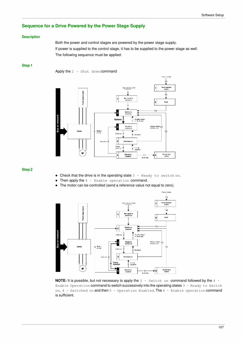
Software Setup
107
Sequence for a Drive Powered by the Power Stage Supply
Description
Both the power and control stages are powered by the power stage supply.
If power is supplied to the control stage, it has to be supplied to the power stage as well.
The following sequence must be applied:
Step 1
Step 2
Apply the 2 - Shut down command
� Check that the drive is in the operating state 3 - Ready to switch on.
� Then apply the 4 - Enable operation command.
� The motor can be controlled (send a reference value not equal to zero).
NOTE: It is possible, but not necessary to apply the 3 - Switch on command followed by the 4 -
Enable Operation command to switch successively into the operating states 3 - Ready to Switch
on, 4 - Switched on and then 5 - Operation Enabled. The 4 - Enable operation command
is sufficient.

Software Setup
108
Sequence for a Drive with Separate Control Stage
Description
Power is supplied separately to the power and control stages.
If power is supplied to the control stage, it does not have to be supplied to the power stage as well.
The following sequence must be applied:
Step 1
� The power stage supply is not necessarily present.
� Apply the 2 - Shut down command

Software Setup
109
Step 2
� Check that the drive is in the operating state 3 - Ready to switch on.
� Check that the power stage supply is present (Voltage enabled of the status word).
Power Stage Supply Terminal Display Status Word
Absent nLP 21 hex
Present rdY 31 hex
� Apply the 3 - Switch on command

Software Setup
110
Step 3
� Check that the drive is in the operating state 4 - Switched on.
� Then apply the 4 - Enable operation command.
� The motor can be controlled (send a reference value not equal to zero).
� If the power stage supply is still not present in the operating state 4 - Switched on after a time delay
[Mains V. time out] LCt, the drive triggers an error [Input Contactor] LCF.
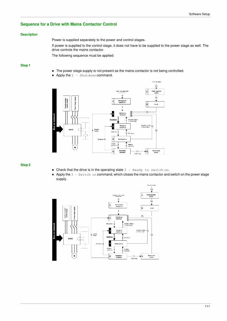
Software Setup
111
Sequence for a Drive with Mains Contactor Control
Description
Power is supplied separately to the power and control stages.
If power is supplied to the control stage, it does not have to be supplied to the power stage as well. The
drive controls the mains contactor.
The following sequence must be applied:
Step 1
Step 2
� The power stage supply is not present as the mains contactor is not being controlled.
� Apply the 2 - Shutdown command.
� Check that the drive is in the operating state 3 - Ready to switch on.
� Apply the 3 - Switch on command, which closes the mains contactor and switch on the power stage
supply.

Software Setup
112
Section 4.5 Embedded Webserver
What Is in This Section?
This section contains the following topics:
Topic Page
Overview 113
Connection to the Webserver 114
My Dashboard 116
Display - Drive 117
Setup - My Preference 118

Software Setup
113
Overview
Webserver
The Ethernet adapter provides an integrated Web server (in six languages) which allows several functions
like: display, parameter settings, and diagnostics. This chapter describes the services provided by this
webserver.
The webserver can be accessed from standard browsers like Internet Explorer, chrome, safari, or Firefox.

Software Setup
114
Connection to the Webserver
Access
The webserver can be accessed from standard browsers.
In the following example, the drive has received the IP address 10.0.0.5:
First connect the computer to the drive by typing http:// followed by the drive IP address.
You are asked to first enter a User Name and a Password.
By default the user name is ADMIN. If you are connecting to the webserver for the first time, the password
is available from the Graphic Display Terminal of the drive in the [Main Menu] / [My preference]
MYP/[Webserver] WbS-/[Webserver default password] WDP menu. Once logged in you are asked to
change the default connection ID (User Name and Password), according to the default security access
rule. Access rules can be modified in the Setup/Access Management web page.
Once connected, the webserver home page is displayed.
Using IPV6 network discovery service, there is no need to set IP parameters. The drive appears
automatically in the network explorer of the PC while physically connected.
The drive is identified as ATV6•••••••-MMMM where MMMM is the two last bytes of the MAC address.
Right-click and select Display device web page to open the webserver.
User Rights - Password and User Names
A new password is required if you are connecting to the webserver for the first time. Default security access
rule requires minimum eight characters for the new password.
The user names and the password of both level can be modified from the administration section.

Software Setup
115
Web Server Site Map
The descriptions of the Web server pages are shown in the following table
Page Menu Description
My Dashboard This page can be customized, adding or removing Widgets that
are designed for a quick overview of the drive data.
Display Drive Drive parameters are displayed in data tables. Customized tables
can be created.
Energy Dashboard Trends show information about the energy consumption of the
drive.
Chart Viewer Drive parameters are displayed in charts. Customized charts can
be created.
Diagnostics Drive Drive diagnostics are displayed.
Fieldbus Communication diagnostics are displayed.
Drive Drive Parameter Drives settings can be modified.
Drive Communication Communication settings can be modified.
Setup Fieldbus Drive Ethernet settings can be modified.
File Transfer Drive configuration and reports can be downloaded or loaded
between a computer and the drive.
My Preferences Webserver access and appearance can be handled.

Software Setup
116
My Dashboard
Overview
The following table provides the procedure to add the widget to this page:
Step Action
1 Click the add a widget button.
2 Drag a widget to the desired location.
The following figure shows the widgets that can be added. Various widgets of a same category are
available.

Software Setup
117
Display - Drive
Data Table
The following table provides the procedure to create data tables of drive parameters.
Step Action
1 Type the name of the table. Spaces are not allowed in this field.
2 Select a parameter by clicking the top of the parameter or typing the code and clicking the
button. To delete a parameter while creating the table click the parameter.
3
Click the Add Table button.To remove a table click the button, only visible when the table is
selected.
Chart Viewer
The following table provides the procedure to create a chart viewer.
Step Action
1 Type the name of the chart. Spaces are not allowed in this field.
2 Select the plot frequency.
3 Select the plot frequency unit.
4 Select the number of plot points.
5 Select a parameter by clicking the top of the parameter or typing the code and clicking the
button. To delete a parameter while creating the chart click the parameter. Maximum of five
parameters can be selected.
6
Click the Create Chart button, To remove a chart click the button, only visible when chart is
selected.

Software Setup
118
Setup - My Preference
User Access
In this menu, the access to the Web server can be managed by users with administrator rights. These
users can add, remove, block, unblock, and modify the access rights of other users.
The following table shows the description of the buttons located in this menu:
Button Description
Add a new user, typing the name of the user; the password and the access rights.
Block and unblock the access of a user to the webserver
Change the password. The administrator can change the password of other users.
Themes
In this menu, the aspect of the Web server can be changed. Predefined themes are available, which can
be customized.
The following table provides the procedure for creating new themes
Step Action
1
Click the button.
2 Type the name of the theme. Spaces are not allowed in this field.
3 Type the description of the theme.
4
Upload a logo by clicking the button.
5 Type name of the website.
6 Click the Save button.
Access Management
Select if login credentials are required or not to access to the web server. The password policy can be
changed.
The following table describes the different actions that can be set to enforce the password policy.
Action Description
Enforce Password Policy Enable or disable the password enforcement
Password History Limits the number of failed attempts to access before locking the user account, it
can be set to disable or three and even five attempts.
Special Character Required If enabled, a special character is mandatory when creating a password for a user
account.
Numeric Character If enabled, a numeric character is mandatory when creating a password for a
user account.
Alphabetic Character If enabled, an alphabetical character is mandatory when creating a password for
a user account.
Minimum Password Length If enabled, a preset number of characters is mandatory when creating a
password for a user account.

Software Setup
119
Section 4.6 Fieldbus Integration Using Unity Pro (M580)
What Is in This Section?
This section contains the following topics:
Topic Page
Introduction 120
EtherNet/IP Configuration 120
Configuration of the Master 121
DTM Library 121
DTM Browser 122

Software Setup
120
Introduction
Overview
The following figure shows the basic configuration to control the drive with a M580 PLC. The version of
Unity used here is Unity Pro XL.
EtherNet/IP Configuration
Ethernet Port Configuration
From the project browser, open the EtherNet/IP port configuration by double-clicking the Ethernet port.
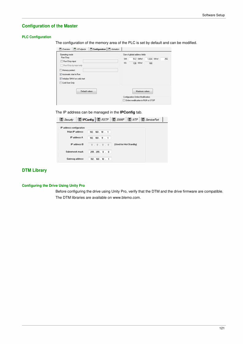
Software Setup
121
Configuration of the Master
PLC Configuration
DTM Library
The configuration of the memory area of the PLC is set by default and can be modified.
The IP address can be managed in the IPConfig tab.
Configuring the Drive Using Unity Pro
Before configuring the drive using Unity Pro, verify that the DTM and the drive firmware are compatible.
The DTM libraries are available on www.blemo.com.

Software Setup
122
DTM Browser
Launch the DTM Using Unity Pro
After installing the DTM library on your PC, restart the Unity Pro to add the DTM to the Unity Pro libraries.
Open the DTM browser to add the drive to the configuration, as shown in the following figure:
Select the drive from the list and click the Add DTM button to add the DTM.
You can select even Modbus or EtherNet/IP communication with this configuration.
Finally the drive used in the configuration can be named with an alias in order to differentiate it in the case
of using other drives. The alias name is used by default as device name for FDR service. The DTM online
help is available in this window.

123
Chapter 5 Operations
What Is in This Chapter?
This chapter contains the following sections:
Section Topic Page
5.1 Operating States 124
5.2 Operating Modes 126

124
Operations
Section 5.1 Operating States
Configuring Communication Error Response
Description
The response of the drive in the event of Ethernet communication interruption can be configured.
Configuration can be performed using the display terminal from the [Complete settings] CSt-,
[Error/Warning handling] CSWM- menu, [Communication Module] COMO- submenu, via the [Fieldbus
Interrupt Resp] CLL parameter.
The values of the [Fieldbus Interrupt Resp] CLL parameter, which triggers a transition to the operating
state fault [Fieldbus Com Interrupt] CnF are:
Value Meaning
[Freewheel Stop] YES Freewheel stop (factory setting)
[Ramp stop] rMP Stop on ramp
[Fast stop] FSt Fast stop
[DC injection] dCI DC injection stop
The values of the [Fieldbus Interrupt Resp] CLL parameter, which does not trigger a transition to the
operating state fault are:
Value Meaning
[Ignore] nO Detected error ignored
[Per STT] Stt Stop according to configuration of [Type of stop] Stt
[Fallback Speed] LFF Change to fallback speed, maintained as long as the detected error
persists and the run command has not been removed
[Speed maintained] rLS The drive maintains the speed at the time the detected error occurred, as
long as the detected error persists, and the run command has not been
removed
The fallback speed can be configured in the [Complete settings] CSt-, [Error/Warning handling]
CSWM- menu, [Fallback speed] LFF- submenu, using the [FallbackSpeed] LFF parameter.
WARNING LOSS OF CONTROL
If this parameter is set to nO, fieldbus communication monitoring is disabled.
Only use this setting after a thorough risk assessment in compliance with all regulations and standards
that apply to the device and to the application.
Only use this setting for tests during commissioning.
Verify that communication monitoring has been re-enabled before completing the commissioning
procedure and performing the final commissioning test.
Failure to follow these instructions can result in death, serious injury, or equipment damage.
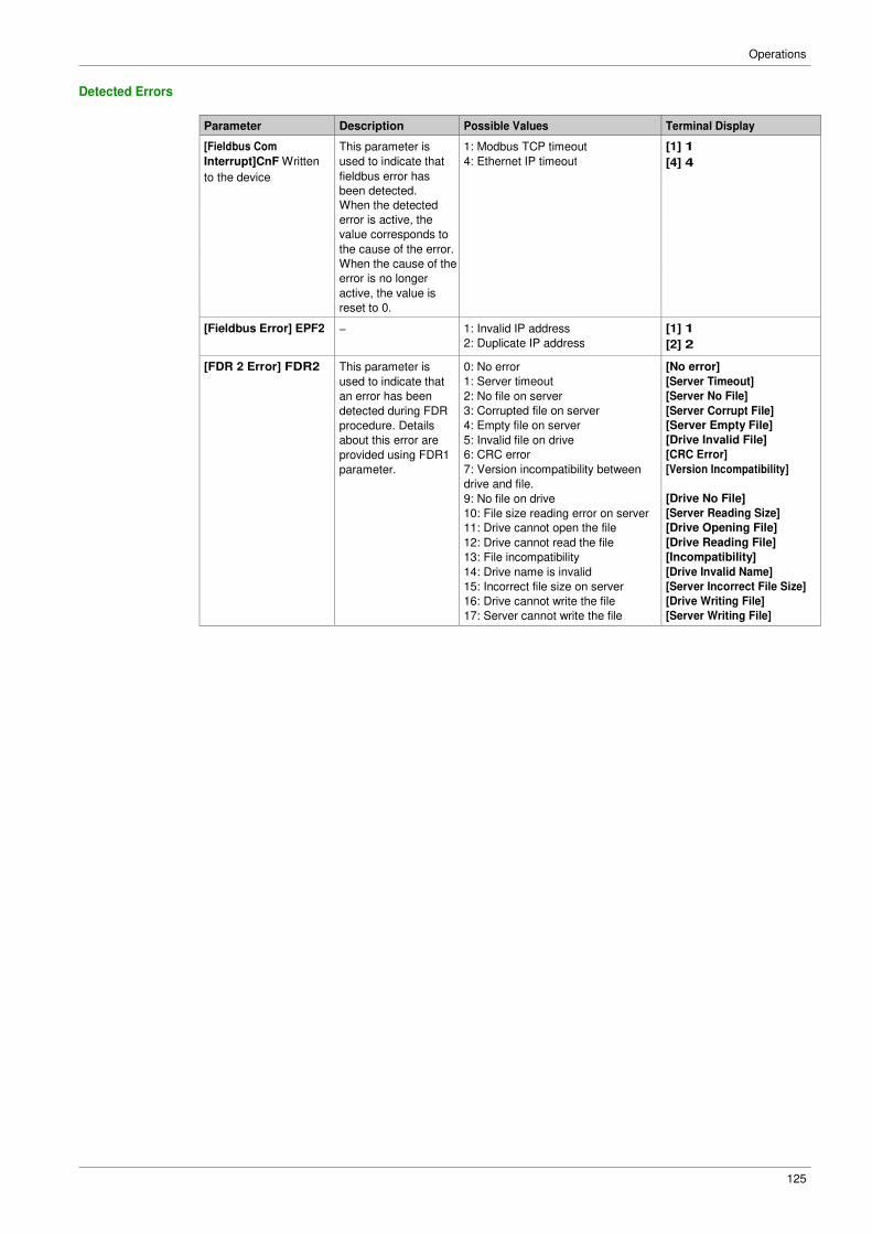
125
Operations
Detected Errors
Parameter Description Possible Values Terminal Display
[Fieldbus Com This parameter is 1: Modbus TCP timeout [1] 1
Interrupt]CnF Written used to indicate that 4: Ethernet IP timeout [4] 4
to the device fieldbus error has been detected. When the detected error is active, the value corresponds to the cause of the error. When the cause of the error is no longer active, the value is reset to 0. [Fieldbus Error] EPF2 − 1: Invalid IP address [1] 1
2: Duplicate IP address [2] 2
[FDR 2 Error] FDR2 This parameter is
used to indicate that
an error has been
detected during FDR
procedure. Details
about this error are
provided using FDR1
parameter.
0: No error
1: Server timeout
2: No file on server
3: Corrupted file on server
4: Empty file on server
5: Invalid file on drive
6: CRC error
7: Version incompatibility between
drive and file.
9: No file on drive
10: File size reading error on server
11: Drive cannot open the file
12: Drive cannot read the file
13: File incompatibility
14: Drive name is invalid
15: Incorrect file size on server
16: Drive cannot write the file
17: Server cannot write the file
[No error]
[Server Timeout]
[Server No File]
[Server Corrupt File]
[Server Empty File]
[Drive Invalid File]
[CRC Error]
[Version Incompatibility]
[Drive No File]
[Server Reading Size]
[Drive Opening File]
[Drive Reading File]
[Incompatibility]
[Drive Invalid Name]
[Server Incorrect File Size]
[Drive Writing File]
[Server Writing File]

126
Operations
Section 5.2 Operating Modes
What Is in This Section?
This section contains the following topics:
Topic Page
Configuring the Control Channel 127
Configuration of the Drive for Operation in I/O Profile 128
Configuration of the Drive for Operation with CiA 402 Profile in Combined Mode 129
Configuration of the Drive for Operation with CiA 402 Profile in Separate Mode 130

127
Operations
Configuring the Control Channel
Overview
This chapter explains how to configure the drive for operation from communication network through three
following examples.
� I/O mode - a simple command word (based on forward, reverse, and reset binary commands).
� Combined mode (with native profile CiA 402) - Both reference value and command word come from the
communication network.
� Separate (with native profile CiA 402) - reference value and command come from separate sources: for
example, the command (in CiA 402) comes from the communication network and the reference value
from the HMI.

128
Operations
Configuration of the Drive for Operation in I/O Profile
Description
For the I/O profile, here is a simple example, which can be extended with additional features. The
command word is made of run forward (bit 0 of CMd), run reverse (bit 1 of CMd), and the function fault
reset (bit 7 of CMd). The reference frequency is given by Graphic Display Terminal.
The settings are the following:
[Ref Freq 1 Config] Fr1 [HMI] HMI
[Control Mode] CHCF [I/O profile] IO
[Command switching] CCS [Cmd Channel 1]CD1
[Cmd channel 1] Cd1 [Com. Module] nEt
The bits of the command word can now be configured.
In the [Command and Reference] CrP- menu configure:
In the [Error/Warning handling] CSWM- menu, [Fault reset] rSt-?submenu, configure:
[Fault Reset Assign] rSF [CD07] Cd07

129
Operations
Configuration of the Drive for Operation with CiA 402 Profile in Combined Mode
Description
This section describes how to configure the settings of the drive if it is controlled in CiA 402 mode. The
example focuses on the not separate mode. Additional modes are detailed in the drive programming
manual.
In the [Complete settings] CSt- menu, [Command and reference] CrP- submenu:
� [Ref Freq Channel 1] Fr1: is set on according to the communication source you can choose in the
following table:
Origin of the Control Ref1 Channel Setting
Ethernet module [Com. Module] nEt
� [Freq Switch Assign] rFC is set to default value ([Ref Freq 1 Config] Fr1).
� [Control Mode] CHCF: defines if the drive operates in combined mode (reference and command from
the same channel).
For the current example, [Control Mode] CHCF is adjusted to [Not separ.] SIM as reference and control
are originated from the communication network:
Profile Ref1 Channel setting
CiA 402 combined mode [Not separ.] SIM
CiA 402 separate mode [Separate] SEp
I/O profile [I/O profile] IO

Operations
130
Configuration of the Drive for Operation with CiA 402 Profile in Separate Mode
Description
Alternate combinations are possible, see the drive programming manual for the list of possible settings.
For example:
The drive is controlled from the communication but the reference value is adjusted on the display terminal.
The control word comes from the controller and is written according to CiA 402 profile.
The settings are as shown in the table:
[Ref Freq 1 Config] Fr1 [HMI] HMI
[Control Mode] CHCF [Separate] SEp
[Cmd channel 1] Cd1 [Com. Module] nEt

131
Chapter 6 Diagnostic and Troubleshooting
What Is in This Chapter?
This chapter contains the following topics:
Topic Page
Fieldbus Status LEDs 132
Connection for Fieldbus Mode 134
Fieldbus Functions Test 135
Control-Signal Diagnostics 137

Diagnostic and Troubleshooting
132
Fieldbus Status LEDs
LED Indicators
LED Description
LNK1 and LNK2
The following figure describes the LEDs status for fieldbus monitoring:
Item LED Description
1 LNK1 Indicates port A activity.
2 MS Indicates module status.
3 NS Indicates network status.
4 LNK2 Indicates port B activity.
These LEDs indicate the status of the Ethernet adapter ports:
Color & status Description
OFF No link
Blinking
Green/Yellow
Power on testing
Green ON Link established at 100 Mbit/s
Yellow ON Link established at 10 Mbit/s
Blinking Green Fieldbus activity at 100 Mbit/s
Blinking Yellow Fieldbus activity at 10 Mbit/s
NS: Network Status
This LED indicates the status of the fieldbus.
Color & status Description
OFF The device does not have an IP address or powered off
Blinking Green/Red Power on testing
Green ON A connection is established to control the command word.
Blinking Green Device has a valid IP, but no command word connection.
Red ON Duplicated IP
Blinking Red An established connection to control the command word is closed or timed out

Diagnostic and Troubleshooting
133
MS: Module Status
This LED indicates the status of the adapter
Color & status Description
OFF No power is supplied to the device
Blinking Green/Red Power on testing
Green ON The device is operating correctly.
Blinking Green Device has not been configured.
Blinking red The device has detected a recoverable minor detected error.
Red ON The device has detected a non-recoverable major detected error.

Diagnostic and Troubleshooting
134
Connection for Fieldbus Mode
Description
If the product cannot be addressed via the fieldbus, first check the connections. The product manuals
contains the technical data of the device and information on fieldbus and device installation.
Verify the following:
� Power connections to the device
� Fieldbus cable and fieldbus wiring
� Fieldbus connection to the device
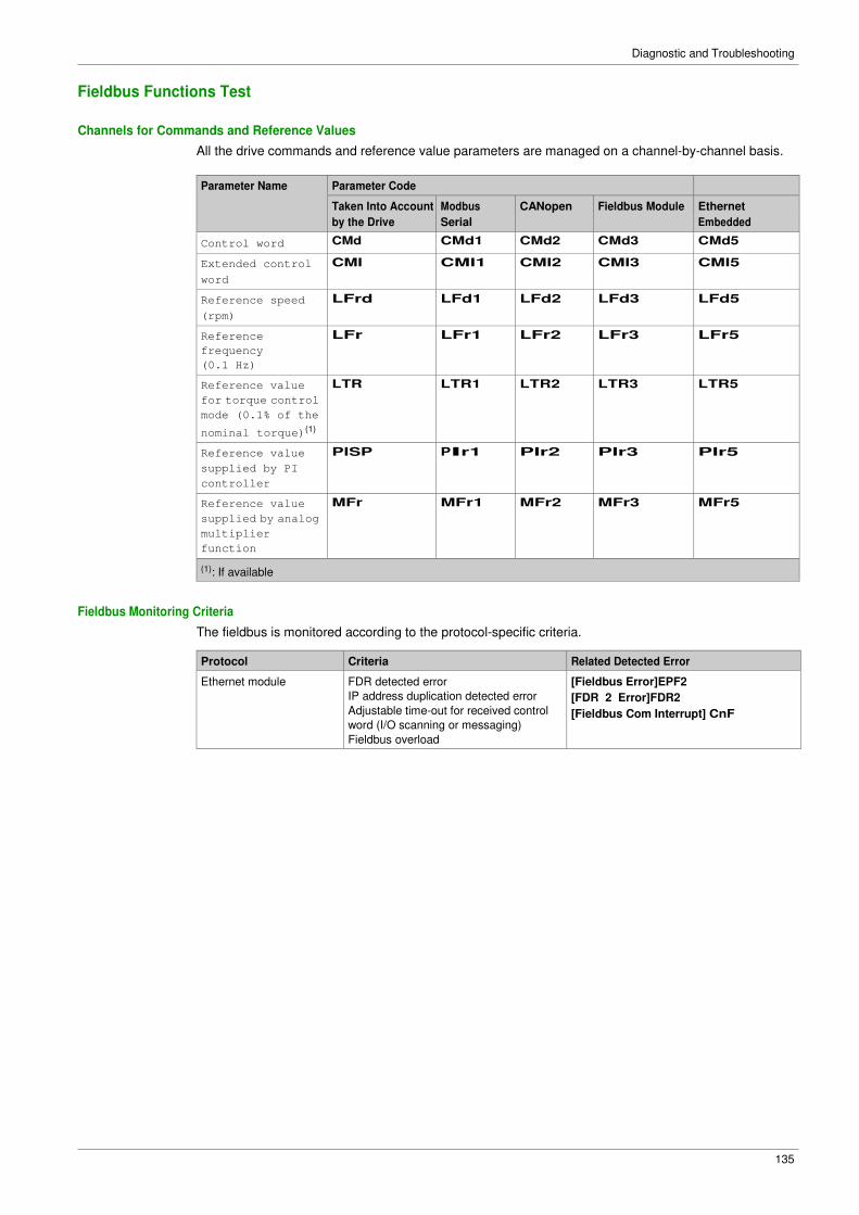
Diagnostic and Troubleshooting
135
Fieldbus Functions Test
Channels for Commands and Reference Values
All the drive commands and reference value parameters are managed on a channel-by-channel basis.
Parameter Name Parameter Code
Taken Into Account
by the Drive
Modbus
Serial
CANopen Fieldbus Module Ethernet
Embedded
Control word CMd CMd1 CMd2 CMd3 CMd5
Extended control
word
CMI CMI1 CMI2 CMI3 CMI5
Reference speed
(rpm)
LFrd LFd1 LFd2 LFd3 LFd5
Reference
frequency
(0.1 Hz)
LFr LFr1 LFr2 LFr3 LFr5
Reference value
for torque control
mode (0.1% of the
nominal torque)(1)
LTR LTR1 LTR2 LTR3 LTR5
Reference value
supplied by PI
controller
PISP PIr1 PIr2 PIr3 PIr5
Reference value
supplied by analog
multiplier
function
MFr MFr1 MFr2 MFr3 MFr5
(1): If available
Fieldbus Monitoring Criteria
The fieldbus is monitored according to the protocol-specific criteria.
Protocol Criteria Related Detected Error
Ethernet module FDR detected error
IP address duplication detected error
Adjustable time-out for received control
word (I/O scanning or messaging)
Fieldbus overload
[Fieldbus Error]EPF2
[FDR 2 Error]FDR2
[Fieldbus Com Interrupt] CnF

Diagnostic and Troubleshooting
136
Monitoring of Communication Channels
Communication channels are monitored if they are involved in one of the following parameters: � The control word ([Cmd Register] CMd) from the active command channel
� The control word containing the command switch (bit configured on [Cmd switching] CCS)
� The control word containing the switch for reference value 1'1B (bit configured on [Ref 1B switching]
rCb)
� The control word containing the switch for reference value 1'2 (bit configured on [Freq Switch Assign]
rFC)
� The reference frequency or reference speed ([Ref Frequency] LFr or LFRD: Nominal speed value)
from the active channel for reference value
� Summing reference frequency or reference speed ([Ref Frequency] LFr or LFRD: Nominal speed
value) 2 (assigned to [Summing Input 2] SA2)
� Summing reference frequency or reference speed ([Ref Frequency] LFr or LFRD: Nominal speed
value) 3 (assigned to [Summing Input 3] SA3)
� Subtracting reference frequency or reference speed ([Ref Frequency] LFr or LFRD: Nominal speed
value) 2 (assigned to [Subtract Ref Freq 2] dA2)
� Subtracting reference frequency or reference speed ([Ref Frequency] LFr or LFRD: Nominal speed
value) 3 (assigned to [Subtract Ref Freq 3] dA3)
� The reference value given by the PID controller (PISP)
� The PID controller feedback ([AI Virtual 1] AIU1)
� The multiplication coefficient of the reference values ([Multiplying coeff.] MFr) 2 (assigned to [Ref Freq
2 Multiply] MA2)
� The multiplication coefficient of the reference values ([Multiplying coeff.] MFr) 3 (assigned to [Ref Freq
3 Multiply] MA3)
As soon as one of these parameters has been written once to a communication channel, it activates
monitoring for that channel.
If a communication warning is sent (in accordance with the protocol criteria) by a monitored port or fieldbus
module, the drive triggers a communication interruption.
The drive reacts according to the communication interruption configuration (operating state Fault,
maintenance, fallback, and so on)
If a communication warning occurs on a channel that is not being monitored, the drive does not trigger a
communication interruption.
Enabling of Communication Channels
A communication channel is enabled once all the parameters involved have been written at least one
time.The drive is only able to start if all channels involved in command and reference value are enabled.
For example:
A drive in DSP402 profile is connected to an active communication channel.
It is mandatory to write at least 1 time the reference value and the command in order to switch from 4-
Switched on to 5-Operation enabled state.
A communication channel is disabled:
� In the event of a communication warning.
� In forced local mode.
NOTE: On exiting forced local mode:
� The drive copies the run commands, the direction, and the forced local reference value to the active
channel (maintained).
� Monitoring of the active channels for the command and reference value resumes following a time delay
[Time-out forc. local] FLOt.
� Drive control only takes effect once the d rive has received the reference and the command from the
active channels.

Diagnostic and Troubleshooting
137
Control-Signal Diagnostics
Introduction
On the display terminal, the [Display] MON-, [Communication map] CMM- submenu can be used to
display control-signal diagnostic information between the drive and the controller:
� Active command channel [Command Channel] CMdC
� Value of the control word [Cmd Register] CMd from the active command channel [Command Channel]
CMdC
� Active reference frequency channel [Ref Freq Channel] rFCC
� Value of the reference frequency [Pre-Ramp Ref Freq] FrH from the active target channel [Ref Freq
Channel] rFCC
� Value of the operating state word [CIA402 State Reg] EtA
� Specific data for all available fieldbusses are in dedicated submenus.
� In the [Command word image] CWI- submenu: control words from all channels
� In the [Freq. ref. word map] rWI- submenu: reference frequency values produced by all channels
Control Word Display
The [Command Channel] CMdC parameter indicates the active command channel.
The [Cmd Register] CMd parameter indicates the hexadecimal value of the control word (CMD) used to
control the drive.
The [Command word image] CWI- submenu ([COM. Module cmd.] CMd3) parameter is used to
display the hexadecimal value of the control word from the fieldbus module.
Reference Frequency Display
The [Ref Freq Channel] rFCC parameter indicates the active channel for reference frequency.
The [Ref Frequency] LFr parameter indicates the value (in 0.1 Hz units) of the reference frequency used
to control the drive.
The [Freq. ref. word map] rWI- submenu ([COM Module Ref Freq] LFr3) parameter is used to
display the value (in 0.1 Hz units) of the reference frequency from the fieldbus.
Operating State Word Display
The [CIA402 State Reg] EtA parameter gives the value of the operating state word (ETA).
The table provides the bit details of ETA parameter:
Bit Description
DRIVECOM Status word
Bit0 = 1 Ready to switch on
Bit1 = 1 Switched on
Bit2 = 1 Operation enabled
Bit3 = 1 Operating state fault
Bit4 = 1 Power stage is switched on
Bit5 = 0 Quick stop
Bit6 = 1 Switch on disabled
Bit7 = 1 Warning
Bit8 = 1 Drivecom reserved
Bit9 = 0 Forced local mode in progress
Bit10 = 1 Reference value reached (steady state)
Bit11 = 1 Reference value exceeded (< LSP or > HSP)
Bit12 Reserved
Bit13 Reserved
Bit14 = 1 Stop imposed via STOP key
Bit15 = 0 Motor rotation in forward direction (or stopped)

Diagnostic and Troubleshooting
138
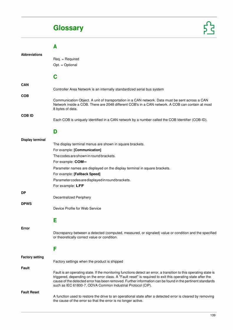
139
Glossary
A
Abbreviations
CAN
COB
COB ID
Req. = Required
Opt. = Optional
C
Controller Area Network is an internally standardized serial bus system
Communication Object. A unit of transportation in a CAN network. Data must be sent across a CAN
Network inside a COB. There are 2048 different COB's in a CAN network. A COB can contain at most
8 bytes of data.
Each COB is uniquely identified in a CAN network by a number called the COB Identifier (COB-ID).
D
Display terminal
DP
DPWS
Error
The display terminal menus are shown in square brackets.
For example: [Communication]
The codes are shown in round brackets.
For example: COM-
Parameter names are displayed on the display terminal in square brackets.
For example: [Fallback Speed]
Parameter codes are displayed in round brackets.
For example: LFF
Decentralized Periphery
Device Profile for Web Service
E
Discrepancy between a detected (computed, measured, or signaled) value or condition and the specified
or theoretically correct value or condition.
F
Factory setting
Fault
Fault Reset
Factory settings when the product is shipped
Fault is an operating state. If the monitoring functions detect an error, a transition to this operating state is
triggered, depending on the error class. A "Fault reset" is required to exit this operating state after the
cause of the detected error has been removed. Further information can be found in the pertinent standards
such as IEC 61800-7, ODVA Common Industrial Protocol (CIP).
A function used to restore the drive to an operational state after a detected error is cleared by removing
the cause of the error so that the error is no longer active.

140
Glossary
L
LSB
Least Significant Byte
M
Monitoring function
MS0, MS1
MSB
NMT
Monitoring functions acquire a value continuously or cyclically (for example, by measuring) in order to
check whether it is within permissible limits. Monitoring functions are used for error detection.
Number of a master in the network.
Most Significant Byte
N
Network Management. One of the service elements of the application layer in the CAN Reference Model.
The NMT serves to configure, initialize, and handle detected errors in a CAN network.
P
Parameter
PDO
PELV
PLC
PNO
Power stage
QoS
Quick Stop
RPDO
SNMP
SNTP
Device data and values that can be read and set (to a certain extent) by the user.
Process Data Object
Protective Extra Low Voltage, low voltage with isolation. For more information: IEC 60364-4-41
Programmable logic controller
PROFIBUS Nutzerorganisation e.V. (PROFIBUS User organization).
The power stage controls the motor. The power stage generates current for controlling the motor.
Q
Quality of Service
The quick Stop function can be used for fast deceleration of a movement as a response to a detected error
or via a command.
R
Receive PDO
S
Simple Network Management Protocol
Simple Network Time Protocol

141
Glossary
SYNC Synchronization Object
T
TPDO
Transmit PDO
W
Warning
If the term is used outside the context of safety instructions, a warning alerts to a potential problem that
was detected by a monitoring function. A warning does not cause a transition of the operating state.
Z
Zone of operation
This term is used in conjunction with the description of specific hazards, and is defined as it is for a hazard
zone or danger zone in the EC Machinery Directive (2006/42/EC) and in ISO 12100-1.

Glossary
142


ER41_EthernetIP_Modbus/TCP_Manual
09/2017
BLEMO Frequenzumrichter
Siemensstraße 4 D-63110 Rodgau – Dudenhofen
Tel.: +49 / 6106 / 82 95-0 Fax: +49 / 6106 / 82 95-20 Internet: www.blemo.com E-Mail: [email protected]