Embed Size (px)
Citation preview

05

2
IntroductionThis electric hoist ER2 is designed and manufactured for the purpose to lift and lower a load within a normal work environment. The motorized trolley MR2 and the manual trolley are designed and manufactured for the purpose to move the lifted load laterally with the combination with the electric hoist. Movement of a load in a 3D direction such as up/down, forward/backward and right/left is also enabled by combining with a crane.
This Owner's Manual is intended for those operating the KITO electric hoist ER2 and maintenance engineers (* pesonnel with expertise). Other than this manual, Disassembly/Reassembly Manual and Parts List are also available for the maintenance engineers. Assign the maintenance engineers and use these materials for inspection and repair. Please contact the nearest distributor or KITO for these materials.
Table of Contents
Disclaimer ■ KITO shall not be liable for any damage incurred thereof due to natural disaster such as fire, earth quake and ●
thunderbolt, conduct by third party, accident, willful conduct or negligence by customer, erroneous use and other use exceeding the operational condition. KITO shall not be liable for any incidental damage due to the use or non-use of the product such as the loss of ●
business profit, suspension of business and damage of the lifted load. KITO shall not be liable for any damage arising from negligence of the contents in the Owner's Manual and the ●
use of the product exceeding the scope of its specification. KITO shall not be liable for any damage arising from the malfunction due to the combination of the product with ●
other devices in which KITO is not concerned. KITO shall be indemnified from any loss of life, bodily injury and property damage due to the use of our product ●
for which it has passed 10 years since its delivery. KITO shall not be liable to supply the spare parts for the product for which it has passed for 15 years since the ●
discontinue of the product.
Introduction ............................................................................................2
Safety Precautions ................................................................................4
Chapter 1 Handling the Product ..........................................................7
Chapter 2 Inspection ..........................................................................63
Chapter 3 Troubleshooting ................................................................93
Appendix ............................................................................................119
Warranty .............................................................................................160
3
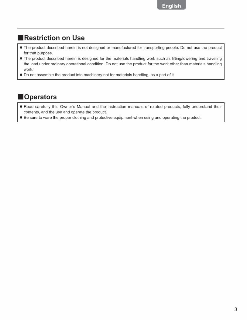
Restriction on Use ■ The product described herein is not designed or manufactured for transporting people. Do not use the product ●
for that purpose. The product described herein is designed for the materials handling work such as lifting/lowering and traveling ●
the load under ordinary operational condition. Do not use the product for the work other than materials handling work. Do not assemble the product into machinery not for materials handling, as a part of it. ●
Operators ■ Read carefully this Owner’s Manual and the instruction manuals of related products, fully understand their ●
contents, and the use and operate the product. Be sure to ware the proper clothing and protective equipment when using and operating the product. ●
4
General Matters on Handling and Control ■
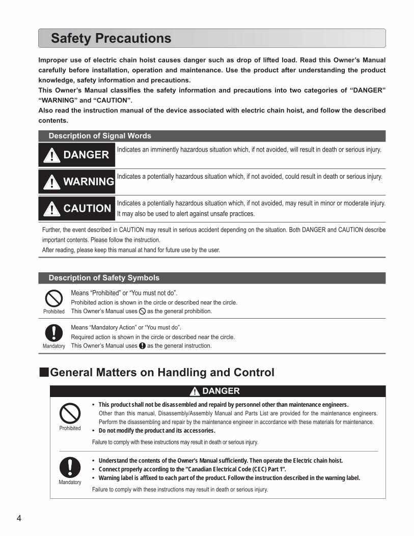
This product shall not be disassembled and repaird by personnel other than maintenance engineers. •Other than this manual, Disassembly/Assembly Manual and Parts List are provided for the maintenance engineers. Perform the disassembling and repair by the maintenance engineer in accordance with these materials for maintenance.Do not modify the product and its accessories. •
Failure to comply with these instructions may result in death or serious injury.
Prohibited
Mandatory
Understand the contents of the Owner’s Manual sufficiently. Then operate the Electric chain hoist. •Connect properly according to the “Canadian Electrical Code (CEC) Part 1”. •Warning label is affixed to each part of the product. Follow the instruction described in the warning label. •
Failure to comply with these instructions may result in death or serious injury.
Safety PrecautionsImproper use of electric chain hoist causes danger such as drop of lifted load. Read this Owner’s Manual carefully before installation, operation and maintenance. Use the product after understanding the product knowledge, safety information and precautions. This Owner’s Manual classifies the safety information and precautions into two categories of “DANGER” “WARNING” and “CAUTION”.Also read the instruction manual of the device associated with electric chain hoist, and follow the described contents.
Description of Safety Symbols
Means “Prohibited” or “You must not do”.Prohibited action is shown in the circle or described near the circle.This Owner’s Manual uses as the general prohibition.
Means “Mandatory Action” or “You must do”.Required action is shown in the circle or described near the circle.This Owner’s Manual uses as the general instruction.
Further, the event described in CAUTION may result in serious accident depending on the situation. Both DANGER and CAUTION describe important contents. Please follow the instruction.After reading, please keep this manual at hand for future use by the user.
Indicates an imminently hazardous situation which, if not avoided, will result in death or serious injury.
Description of Signal Words
WARNING
DANGER
CAUTION
Indicates a potentially hazardous situation which, if not avoided, could result in death or serious injury.
Indicates a potentially hazardous situation which, if not avoided, may result in minor or moderate injury. It may also be used to alert against unsafe practices.
Prohibited
Mandatory
DANGER
5
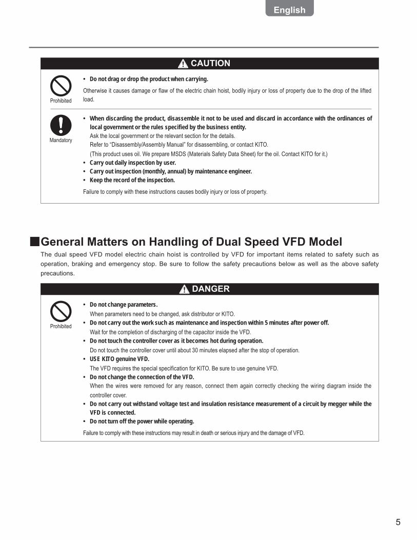
CAUTIONDo not drag or drop the product when carrying. •
Otherwise it causes damage or flaw of the electric chain hoist, bodily injury or loss of property due to the drop of the lifted load.Prohibited
Mandatory
When discarding the product, disassemble it not to be used and discard in accordance with the ordinances of •local government or the rules specified by the business entity.Ask the local government or the relevant section for the details.Refer to “Disassembly/Assembly Manual” for disassembling, or contact KITO.(This product uses oil. We prepare MSDS (Materials Safety Data Sheet) for the oil. Contact KITO for it.)Carry out daily inspection by user. •Carry out inspection (monthly, annual) by maintenance engineer. •Keep the record of the inspection. •
Failure to comply with these instructions causes bodily injury or loss of property.
General Matters on Handling of Dual Speed VFD Model ■The dual speed VFD model electric chain hoist is controlled by VFD for important items related to safety such as operation, braking and emergency stop. Be sure to follow the safety precautions below as well as the above safety precautions.
Do not change parameters. •When parameters need to be changed, ask distributor or KITO.Do not carry out the work such as maintenance and inspection within 5 minutes after power off. •Wait for the completion of discharging of the capacitor inside the VFD.Do not touch the controller cover as it becomes hot during operation. •Do not touch the controller cover until about 30 minutes elapsed after the stop of operation.USE KITO genuine VFD. •The VFD requires the special specification for KITO. Be sure to use genuine VFD.Do not change the connection of the VFD. •When the wires were removed for any reason, connect them again correctly checking the wiring diagram inside the controller cover.Do not carry out withstand voltage test and insulation resistance measurement of a circuit by megger while the •VFD is connected.Do not turn off the power while operating. •
Failure to comply with these instructions may result in death or serious injury and the damage of VFD.
Prohibited
DANGER

6
7
Chapter 1Handling the Product
This chapter describes mainly how to use, assemble and install, and the check after installation. It also describes the daily inspection items before use.
● For Operators and Maintenance Engineers
Type and Names of Each Part ..........................................................8Opening the Package ......................................................................11Product Specifi cation and Operational Environment ..................16How to Use ......................................................................................19
Daily Inspection of Electric Chain Hoist (Hook Suspended Type) ● 20Daily Inspection of Motorized Trolley (MR2) ● .............................25Daily Inspection of Manual Trolley (TSG/TSP) ● ..........................26How to Operate the Push Button Switches ● ...............................28Operation ● ......................................................................................31Speed Change of Dual Speed VFD Model ● .................................34How to Sling the Load Properly ● .................................................34How to Suppress the Swinging of a Load ● .................................34Precautions After Work ● ...............................................................35
● For Maintenance Engineers and Installars
Work Flow of Assembling and Installation....................................36Assembling ......................................................................................37
Assembling Parts to Electric Chain Hoist ● .................................37Combination with the Trolley ● ......................................................41Checking Power and Power Cable ● .............................................52Connecting Cables ● ......................................................................54
Installation ........................................................................................57Connecting Power and Power cable ● ..........................................57Installing the Hook suspended Type (hoist only) ● .........................57Installing the Trolley Combined Model ● .......................................58
Check after Installation ...................................................................61

8
1
Chapter 1 Handling the Product
Type and Names of Each Part
Mandatory
Warning labels are affixed to each part other than above. Be sure to follow the instructions in the label. •Failure to comply with the contents of the label may result in death or serious injury.
Hook Suspended Type (ER2) ■Electric chain hoist dedicated for elevation ●
Chain Container
Electric Chain hoist name plate
Top Hook
Push Button Switch Cord
Warning Tag
Load Chain
Cushion Rubber(Chain spring and end plate for the model of rated load 2 t or more)
Body
Bottom YokeHook LatchBottom Hook
Push Button Switch
Type
and
Nam
es o
f Eac
h Pa
rtH
ook
Susp
ende
d Ty
pe (E
R2)
DANGER
9
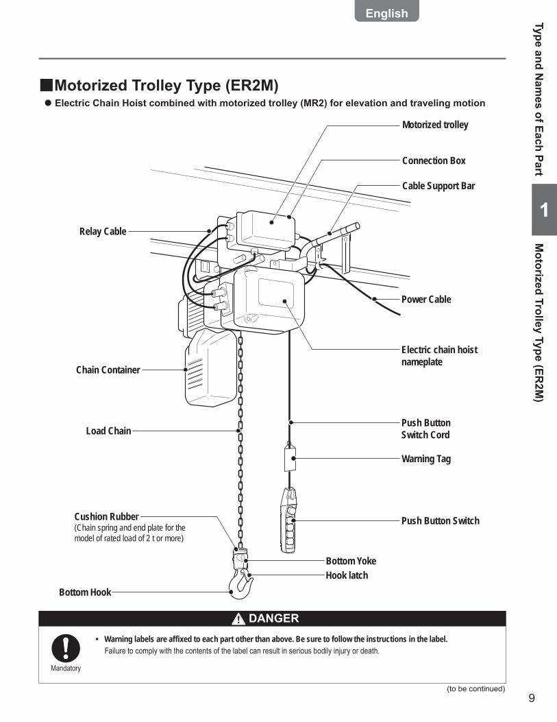
11Relay Cable
Chain Container
Cushion Rubber(Chain spring and end plate for the model of rated load of 2 t or more)
Bottom Hook
Load Chain
Electric chain hoist nameplate
Connection Box
Motorized trolley
Cable Support Bar
Push Button Switch Cord
Hook latch
Power Cable
Push Button Switch
Warning Tag
Bottom Yoke
Motorized Trolley Type (ER2M) ■Electric Chain Hoist combined with motorized trolley (MR2) for elevation and traveling motion ●
Type and Nam
es of Each PartM
otorized Trolley Type (ER2M
)
(to be continued)
Mandatory
Warning labels are affixed to each part other than above. Be sure to follow the instructions in the label. •Failure to comply with the contents of the label can result in serious bodily injury or death.
DANGER
10
1
Chapter 1 Handling the Product
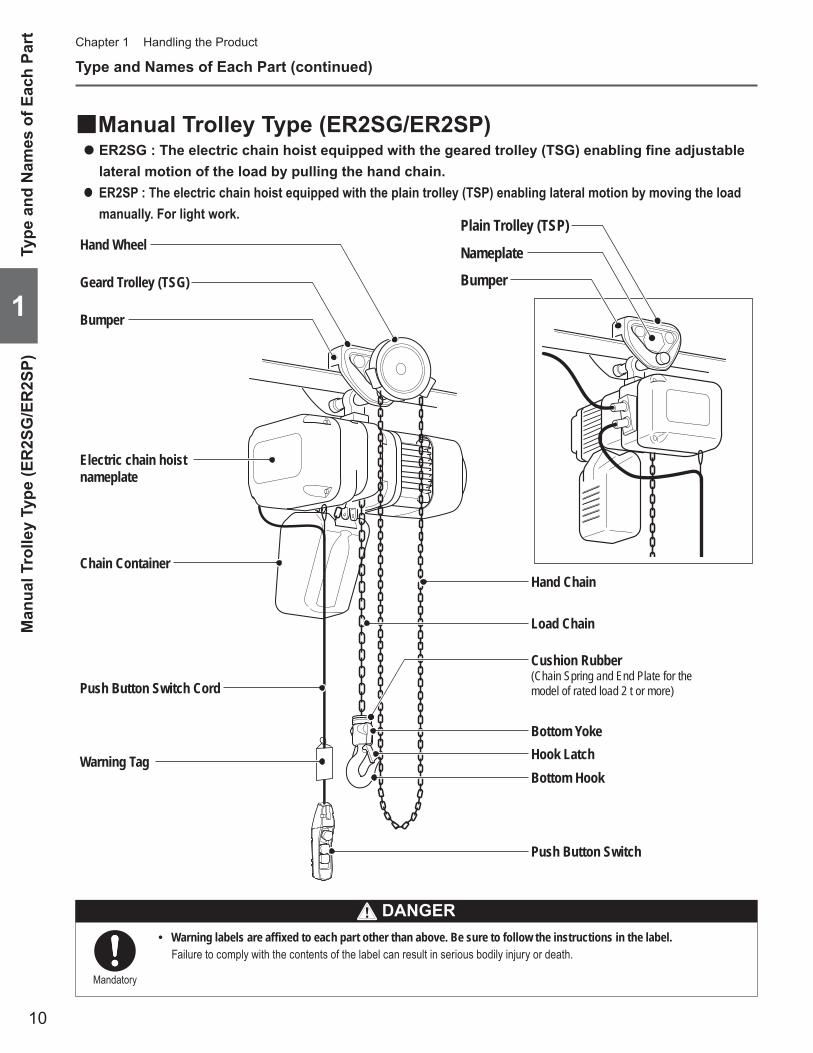
Manual Trolley Type (ER2SG/ER2SP) ■ER2SG : The electric chain hoist equipped with the geared trolley (TSG) enabling fine adjustable ●
lateral motion of the load by pulling the hand chain.ER2SP : The electric chain hoist equipped with the plain trolley (TSP) enabling lateral motion by moving the load ●
manually. For light work.
Type and Names of Each Part (continued)
Chain Container
Electric chain hoist nameplate
Push Button Switch Cord
Warning Tag
Load Chain
Cushion Rubber(Chain Spring and End Plate for the model of rated load 2 t or more)
Hand Chain
Bottom YokeHook LatchBottom Hook
Push Button Switch
Geard Trolley (TSG)
Bumper
Hand Wheel Nameplate
Plain Trolley (TSP)
Bumper
Type
and
Nam
es o
f Eac
h Pa
rtM
anua
l Tro
lley
Type
(ER
2SG
/ER
2SP)
Mandatory
Warning labels are affixed to each part other than above. Be sure to follow the instructions in the label. •Failure to comply with the contents of the label can result in serious bodily injury or death.
DANGER

11
11
Opening the Package
Checking the Product ■Make sure that the indication on the package and the product coincide with your order. ●
Make sure that the product is not deformed and damaged due to the accident during transportation. ●
Packaging ■Packaging ■For the customer's convenience, the main parts of our product are packaged individually and delivered.
Trolley packaging
TSP Plain Trolley
TSG Geared Trolley
Model MR2 Motorized Trolley
5-PushButtonSwitch set
PowerCable
PowerCable
* Power Cable longer than 10 m is available as an optional part.
Control Box7-PushButtonSwitch set
3-PushButtonSwitch set
Equipped with Top Hook
Equipped with Connection Yoke
Equipped with Suspender
Hook Suspended Model
Plain Trolley Combined Model
Geared Trolley Combined Model
Motorized Trolley Type
Crane
PowerCable set
Accessory setElectric chain hoist main
unit packaging
Option
Applicable model
ER2
ER2SP, ER2SG
ER2M
Parts packaged with the Electric Chain Hoist ■
Plastic or canvas Chain Container (Option) Owner's Manual Load Chain
Grease Tube
Opening the Package
Checking the Product / Packaging
(to be continued)
12
1
Chapter 1 Handling the Product
Opening the Package (continued)
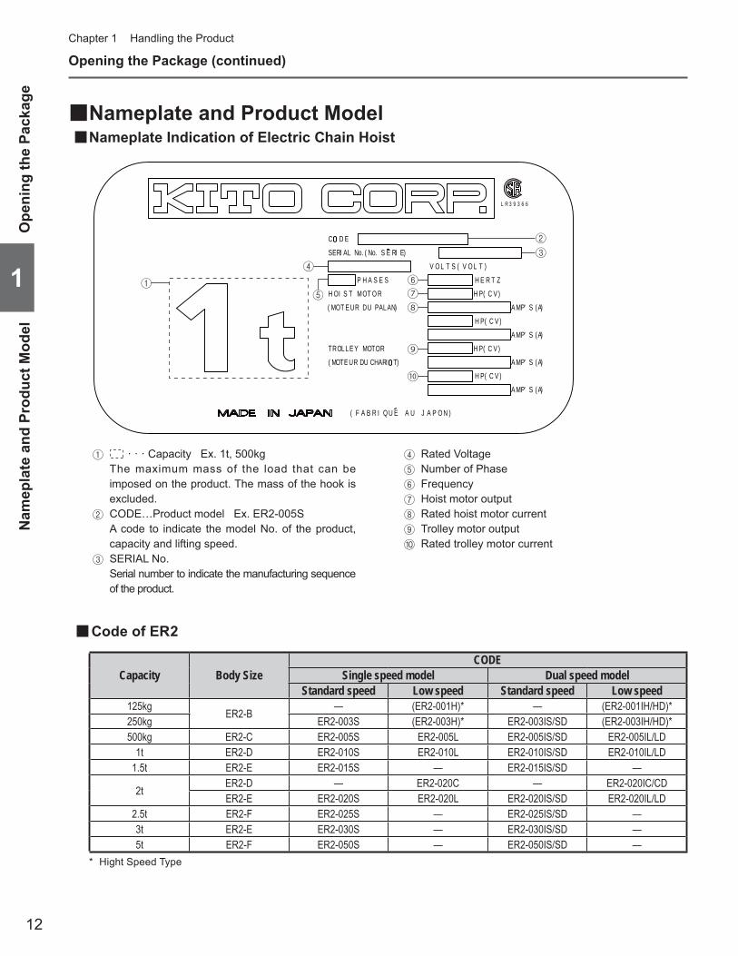
Nameplate and Product Model ■Nameplate Indication of Electric Chain Hoist ■
Capacity Body SizeCODE
Single speed model Dual speed modelStandard speed Low speed Standard speed Low speed
125kg ER2-B — (ER2-001H)* — (ER2-001IH/HD)*250kg ER2-003S (ER2-003H)* ER2-003IS/SD (ER2-003IH/HD)*500kg ER2-C ER2-005S ER2-005L ER2-005IS/SD ER2-005IL/LD
1t ER2-D ER2-010S ER2-010L ER2-010IS/SD ER2-010IL/LD1.5t ER2-E ER2-015S — ER2-015IS/SD —
2t ER2-D — ER2-020C — ER2-020IC/CDER2-E ER2-020S ER2-020L ER2-020IS/SD ER2-020IL/LD
2.5t ER2-F ER2-025S — ER2-025IS/SD —3t ER2-E ER2-030S — ER2-030IS/SD —5t ER2-F ER2-050S — ER2-050IS/SD —
Hight Speed Type*
2
34
5
6
⑦⑧
⑨
⑩
1
C D E
STL ( V O L T )OV
H E R T ZP H SA E S
TT MO O RSOH I
M( OT E UR UD PA AN)L
PH )VC(
A PM ' S (A)
)PH ( C V
A MP S' (A)
E Y MO OT RL PH )VC(
UR DU CHARI T) A PM (' S A)ETMO(
TROL
( C V )
A MP' S (A)
PH
SERI AL No. ( No. S E RI E)
NOPAJUARBAF( )I Q U E
R 3 9 3 6 6L
1 · · · Capacity Ex. 1t, 500kg The maximum mass of the load that can be
imposed on the product. The mass of the hook is excluded.
2 CODE…Product model Ex. ER2-005S A code to indicate the model No. of the product,
capacity and lifting speed.3 SERIAL No. Serial number to indicate the manufacturing sequence
of the product.
4 Rated Voltage5 Number of Phase6 Frequency7 Hoist motor output8 Rated hoist motor current9 Trolley motor output0 Rated trolley motor current
Code of ER2 ■
Ope
ning
the
Pack
age
Nam
epla
te a
nd P
rodu
ct M
odel
13
11
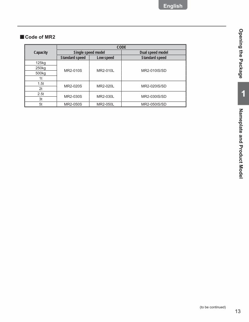
CapacityCODE
Single speed model Dual speed modelStandard speed Low speed Standard speed
125kg
MR2-010S MR2-010L MR2-010IS/SD250kg500kg
1t1.5t
MR2-020S MR2-020L MR2-020IS/SD2t
2.5tMR2-030S MR2-030L MR2-030IS/SD
3t5t MR2-050S MR2-050L MR2-050IS/SD
Opening the Package
Nam
eplate and Product Model
(to be continued)
Code of MR2 ■
14
1
Chapter 1 Handling the Product
Opening the Package (continued)
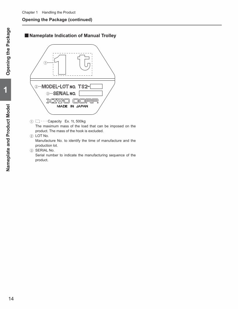
Nameplate Indication of Manual Trolley ■
1 · · · Capacity Ex. 1t, 500kg The maximum mass of the load that can be imposed on the
product. The mass of the hook is excluded.2 LOT No. Manufacture No. to identify the time of manufacture and the
production lot.3 SERIAL No. Serial number to indicate the manufacturing sequence of the
product.
1
2
3
Ope
ning
the
Pack
age
Nam
epla
te a
nd P
rodu
ct M
odel
15
11
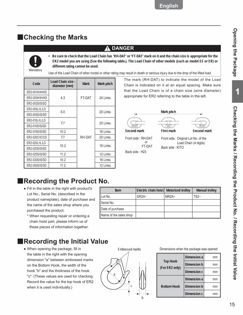
Checking the Marks ■
Code Load Chain size : diameter (mm) Mark Mark pitch
ER2-001H/IH/HD4.3 FT-DAT 24 LinksER2-003H/IH/HD
ER2-003S/IS/SDER2-005L/IL/LD
6.0
RH-DAT
20 LinksER2-005S/IS/SDER2-010L/IL/LD
7.7 20 LinksER2-010S/IS/SDER2-015S/IS/SD 10.2 16 LinksER2-020C/IC/CD 7.7 20 LinksER2-020L/IL/LD
10.2 16 LinksER2-020S/IS/SDER2-025S/IS/SD 11.2 12 LinksER2-030S/IS/SD 10.2 16 LinksER2-050S/IS/SD 11.2 12 Links
RH-DAT 0000 RH-DAT
Mark pitch
First markSecond mark Second mark
Front side : RH-DAT
Back side : H23
Front side : Original Lot No. of the Load Chain (4 digits)Back side : KITO FT-DAT
or
Be sure to check that the Load Chain has 'RH-DAT' or 'FT-DAT' mark on it and the chain size is appropriate for the •ER2 model you are using (See the following table.). The Load Chain of other models (such as model ES or ER) or different rating cannot be used.
Use of the Load Chain of other model or other rating may result in death or serious injury due to the drop of the lifted load.Mandatory
The mark (RH-DAT) to indicate the model of the Load Chain is indicated on it at an equal spacing. Make sure that the Load Chain is of a chain size (wire diameter) appropriate for ER2 referring to the table in the left.
Recording the Initial Value ■When opening the package, fill in ●the table in the right with the opening dimension "a" between embossed marks on the Bottom Hook, the width of the hook "b" and the thickness of the hook "c". (These values are used for checking. Record the value for the top hook of ER2 when it is used individually.)
Dimensions when the package was opened
b
c
a
Embossed marks
Top Hook(For ER2 only)
Dimension a mm
Dimension b mm
Dimension c mm
Bottom Hook
Dimension a mm
Dimension b mm
Dimension c mm
Recording the Product No. ■Fill in the table in the right with product's ●Lot No., Serial No. (described in the product nameplate), date of purchase and the name of the sales shop where you purchased the product.* When requesting repair or ordering a
chain hoist part, please inform us of these pieces of information together.
Opening the Package
Checking the M
arks / Recording the Product N
o. / Recording the Initial Value
DANGER
Item Electric chain hoist Motorized trolley Manual trolleyLot No. ER2A− MR2A− TS2−Serial No.Date of purchaseName of the sales shop
16
1
Chapter 1 Handling the Product
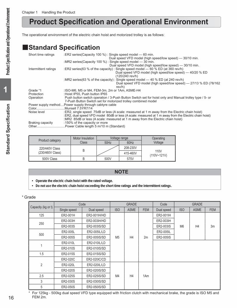
Product Specification and Operational Environment
Standard Specification ■Short time ratings : ER2 series(Capacity 100 %) : Single speed model — 60 min.
Dual speed VFD model (high speed/low speed) — 30/10 min. : MR2 series(Capacity 100 %) : Single speed model — 30 min.
Dual speed VFD model (high speed/low speed) — 30/10 min.Intermittent ratings : ER2 series(63 % of the capacity) : Single speed model — 60 % ED (at 360 rev/h)
Dual speed VFD model (high speed/low speed) — 40/20 % ED (120/240 rev/h)
: MR2 series(63 % of the capacity) : Single speed model — 40 % ED (at 240 rev/h)Dual speed VFD model (high speed/low speed) — 27/13 % ED (78/162 rev/h)
Grade *1 : ISO-M6, M5 or M4, FEM-3m, 2m or 1Am, ASME-H4Protection : Hoist IP55, Push button IP65Operation Push button switch operation / 3-Push Button Switch set for hoist only and Manual trolley type / 5- or
7-Push Button Switch set for motorized trolley combined modelPower supply method....Power supply through cabtyre cableColor...............................Munsell 7.5YR7/14Noise level : ER2, single speed 75dB or less (A scale: measured at 1 m away from the Electric chain hoist) : ER2, dual speed VFD model 80dB or less (A scale: measured at 1 m away from the Electric chain hoist) : MR2 85dB or less (A scale: measured at 1 m away from the Electric chain hoist)Braking capacity : 150% of the capacity or moreOther...............................Power Cable length 5 m/10 m (Standard)
NOTEOperate the electric chain hoist with the rated voltage. •Do not use the electric chain hoist exceeding the short time ratings and the intermittent ratings. •
The operational environment of the electric chain hoist and motorized trolley is as follows:
Produ
ct Spec
ifi catio
n and
Opera
tional
Envir
onme
ntSt
anda
rd S
pecifi c
atio
n
Product category Motor Insulation Class
Voltage range OperatingVoltage50Hz 60Hz
220/440V Class(230/460V Class) B
208-230V110V
(110V~121V)415-460V500V Class B 500V 575V
Capacity (kg or t)Code GRADE Code GRADE
Single speed Dual speed ISO ASME FEM Dual speed ISO ASME FEM125 ER2-001H ER2-001IH/HD
M5 H4 2m
ER2-001IH
M6 H4 3m250
ER2-003H ER2-003IH/HD ER2-003IHER2-003S ER2-003IS/SD ER2-003IS
500ER2-005L ER2-005IL/LD ER2-005ILER2-005S ER2-005IS/SD ER2-005IS
1ER2-010L ER2-010IL/LDER2-010S ER2-010IS/SD
1.5 ER2-015S ER2-015IS/SD
2ER2-020C ER2-020IC/CDER2-020L ER2-020IL/LD
M4 H4 1AmER2-020S ER2-020IS/SD
2.5 ER2-025S ER2-025IS/SD3 ER2-030S ER2-030IS/SD5 ER2-050S ER2-050IS/SD
* Grade
For 125kg - 500kg dual speed VFD type equipped with friction clutch with mechanical brake, the grade is ISO M5 and * FEM 2m.
17
11
Product Specifi cation and Operational EnvironmentStandard Specifi cation
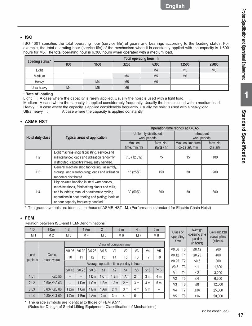
ISO ●
ISO 4301 specifies the total operating hour (service life) of gears and bearings according to the loading status. For example, the total operating hour (service life) of the mechanism when it is constantly applied with the capacity is 1,600 hours for M5. The total operating hour is 6,300 hours when operated with a medium load.
Loading status*Total operating hour h
800 1600 3200 6300 12500 25000Light M4 M5 M6
Medium M4 M5 M6Heavy M4 M5 M6
Ultra heavy M4 M5 M6* Rate of loadingLight : A case where the capacity is rarely applied. Usually the hoist is used with a light load.Medium : A case where the capacity is applied considerably frequently. Usually the hoist is used with a medium load.Heavy : A case where the capacity is applied considerably frequently. Usually the hoist is used with a heavy load.Ultra heavy : A case where the capacity is applied constantly.
ASME HST ●
Hoist duty class Typical areas of application
Operation time ratings at K=0.65Unlformly distributed
work periodsInfrequent
work periodsMax. on
time, min / hrMax. No. starts / hr
Max. on time from cold start, min
Max. No. of starts
H2Light machine shop fabricating, service,and maintenance; loads and utilization randomly distributed; capacitys infrequently handled.
7.6 (12.5%) 75 15 100
H3General machine shop fabricating, assembly, storage, and warehousing; loads and utilization randomly distributed.
15 (25%) 150 30 200
H4
High volume handing in steel warehouses, machine shops, fabricationg plants and mills, and foundries; manual or automatic cycling operations in heat treating and plating; loads at or near capacity frequently handled.
30 (50%) 300 30 300
The grade symbols are identical to those of ASME HST-1M. (Performance standard for Electric Chain Hoist)*
Relation between ISO-and FEM-Denominations1 Dm 1 Cm 1 Bm 1 Am 2 m 3 m 4 m 5 mM 1 M 2 M 3 M 4 M 5 M 6 M 7 M 8
Loadspectrum
Cubicmean value
Class of operation timeV0.06 V0.02 V0.25 V0.5 V1 V2 V3 V4 V5
T0 T1 T2 T3 T4 T5 T6 T7 T8Average operation time per day in hours
0.12 0.25 0.5 1 2 4 8 16 >161 L1 K 0.50 – – 1 Dm 1 Cm 1 Bm 1 Am 2 m 3 m 4 m2 L2 0.50<K 0.63 – 1 Dm 1 Cm 1 Bm 1 Am 2 m 3 m 4 m 5 m3 L3 0.63<K 0.80 1 Dm 1 Cm 1 Bm 1 Am 2 m 3 m 4 m 5 m –4 L4 0.80<K 1.00 1 Cm 1 Bm 1 Am 2 m 3 m 4 m 5 m – –
Class of operating
time
Average operating time
per day (in hours)
Calculated total operating time
(in hours)
V0.06 T0 0.12 200V0.12 T1 0.25 400V0.25 T2 0.5 800V0.5 T3 1 1,600V1 T4 2 3,200V2 T5 4 6,300V3 T6 8 12,500V4 T7 16 25,000V5 T8 >16 50,000
FEM ●
The grade symbols are identical to those of FEM 9.511.* (Rules for Design of Serial Lifting Equipment: Classification of Mechanisms)
(to be continued)
18
1
Chapter 1 Handling the Product
Operational Environment ■Ambient temperature : -20°C — +40°CGradient of rail : No gradient in travel rail (for the hoist with trolley)Ambient humidity : 85 % or less (no condensation)Explosion-proof construction : Not applicable to the work environment with explosive gases or explosive vaporNon-conforming environment : A place with organic solvent or volatile powder, and a place with a plenty of powder and
dust of general substances : A place with considerable amount of acids and salts
NOTEWhen installing the electric chain hoist outdoors or to the place where the hoist is exposed to direct rain, wind and snow, shade the hoist with roof to protect it from rain, wind and snow.
Produ
ct Spec
ifi catio
n and
Opera
tional
Envir
onme
ntO
pera
tiona
l Env
ironm
ent
Product Specification and Operational Environment (continued)
19
11
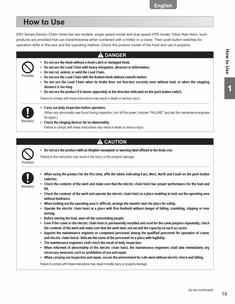
How to Use
Do not use the Hook without a Hook Latch or damaged Hook. •Do not use the Load Chain with heavy elongation, abrasion or deformation. •Do not cut, extend, or weld the Load Chain. •Do not use the Load Chain with the Bottom Hook without smooth motion. •Do not use the Load Chain when its brake does not function securely even without load, or when the stopping •distance is too long.Do not use the product if it moves oppositely to the direction indicated on the push button switch. •
Failure to comply with these instructions may result in death or serious injury.
Carry out daily inspection before operation. •(When any abnormality was found during inspection, turn off the power, indicate “FAILURE" and ask the maintenance engineer for repair.)Check the slinging devices for no abnormality. •Failure to comply with these instructions may result in death or serious injury.
Mandatory
CAUTION
ER2 Series Electric Chain Hoist has two models: single speed model and dual speed VFD model. Other than them, such products are provided that can travel/traverse when combined with a trolley or a crane. Their push button switches for operation differ in the size and the operating method. Check the product model of the hoist and use it properly.
Prohibited
Do not use the product with an illegible nameplate or warning label affixed to the body size. •
Failure to this instruction may result in the injury or the property damage.
When using the product for the first time, affix the labels indicating East, West, North and South on the push button •switches.Check the contents of the work and make sure that the electric chain hoist has proper performance for the load and •lift.Check the contents of the work and operate the electric chain hoist at a place enabling to look out the operating area •without hindrance. When looking out the operating area is difficult, arrange the monitor near the place for safety. •Operate the electric chain hoist at a place with firm foothold without danger of falling, stumbling, slipping or over •turning.Before moving the load, warn all the surrounding people. •Even if the crane or the electric chain hoist is permanently installed and used for the same purpose repeatedly, check •the contents of the work and make sure that the work does not exceed the capacity on each occasion.Appoint the maintenance engineer or competent personnel among the qualified personnel for operation of cranes •and electric chain hoists. Indicate the name of the personnel on a place with legibility.The maintenance engineers shall check the result of daily inspection. •When informed of abnormality of the electric chain hoist, the maintenance engineers shall take immediately any •necessary measures such as prohibition of use and repair. When carrying out inspection and repair, secure the environment for safe work without electric shock and falling. •
Failure to comply with these instructions may result in bodily injury or property damage.
Mandatory
Prohibited
How
to Use
(to be continued)
DANGER
20
1
Chapter 1 Handling the Product
How to use (continued)
Daily Inspection of Electric Chain Hoist (Hook Suspended Type) ■
Carry out daily inspection before use. •(When any abnormality was found during inspection, turn off the power, indicate “FAILURE" and ask the maintenance engineer for repair.)
Neglecting to carry out daily inspection may result in death or serious injury.Mandatory
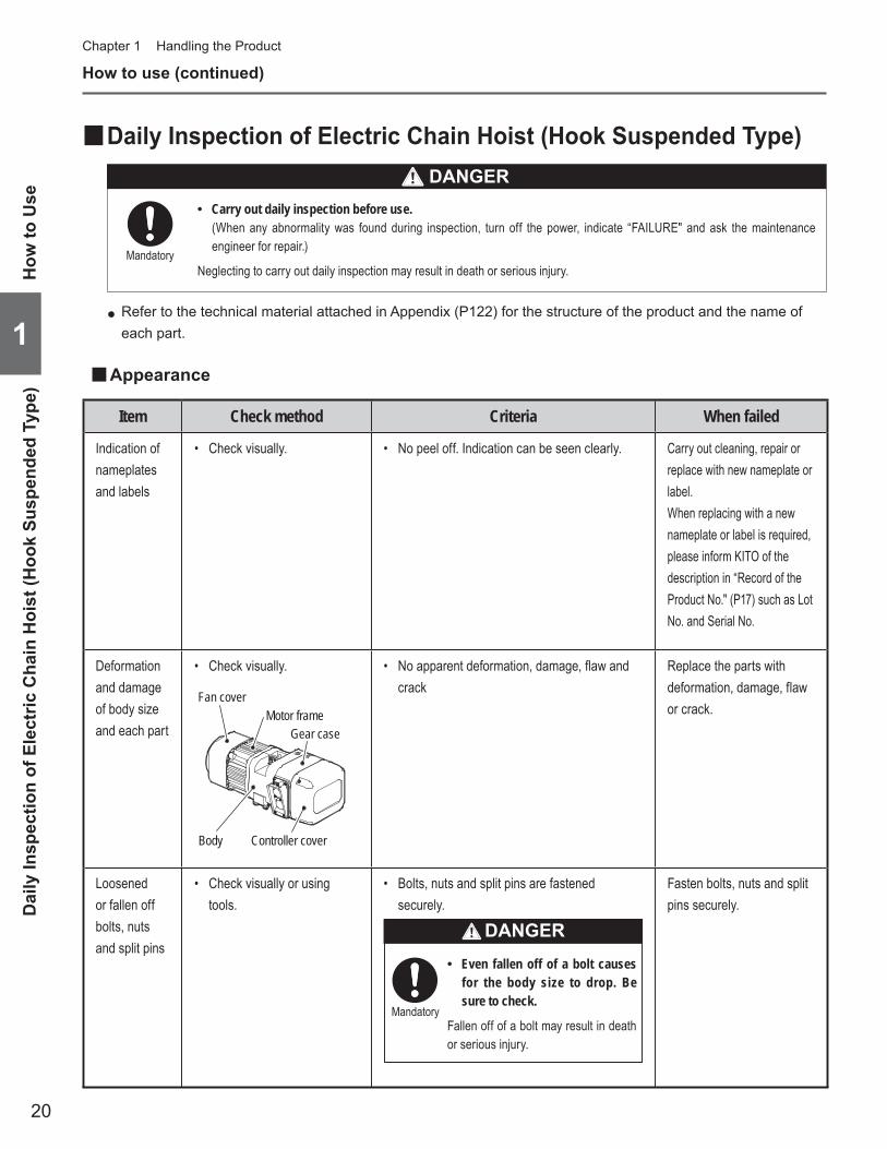
Appearance ■
Item Check method Criteria When failed
Indication of nameplates and labels
Check visually.• No peel off. Indication can be seen clearly.• Carry out cleaning, repair or replace with new nameplate or label.When replacing with a new nameplate or label is required, please inform KITO of the description in “Record of the Product No." (P17) such as Lot No. and Serial No.
Deformation and damage of body size and each part
Check visually.• No apparent deformation, damage, fl aw and • crack
Replace the parts with deformation, damage, flaw or crack.
Loosened or fallen off bolts, nuts and split pins
Check visually or using • tools.
Bolts, nuts and split pins are fastened • securely.
Even fallen off of a bolt causes •for the body size to drop. Be sure to check.
Fallen off of a bolt may result in death or serious injury.
Mandatory
DANGER
Fasten bolts, nuts and split pins securely.
Body
Fan coverMotor frame
Gear case
Controller cover
Refer to the technical material attached in Appendix (P122) for the structure of the product and the name of ●each part.
How
to U
seD
aily
Insp
ectio
n of
Ele
ctric
Cha
in H
oist
(Hoo
k Su
spen
ded
Type
)
DANGER
21
11
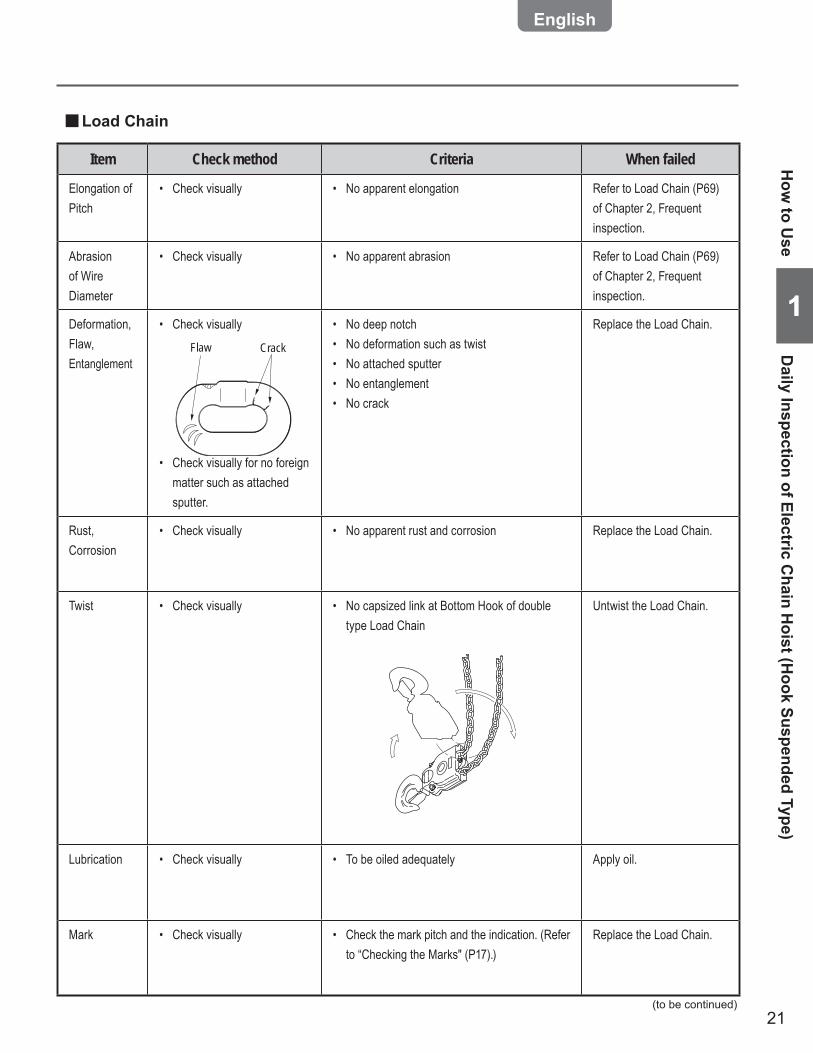
Load Chain ■
Item Check method Criteria When failed
Elongation of Pitch
Check visually• No apparent elongation• Refer to Load Chain (P69) of Chapter 2, Frequent inspection.
Abrasion of Wire Diameter
Check visually• No apparent abrasion• Refer to Load Chain (P69) of Chapter 2, Frequent inspection.
Deformation, Flaw, Entanglement
Check visually•
Flaw Crack
Check visually for no foreign • matter such as attached sputter.
No deep notch • No deformation such as twist• No attached sputter• No entanglement• No crack•
Replace the Load Chain.
Rust, Corrosion
Check visually• No apparent rust and corrosion• Replace the Load Chain.
Twist Check visually• No capsized link at Bottom Hook of double • type Load Chain
Untwist the Load Chain.
Lubrication Check visually• To be oiled adequately• Apply oil.
Mark Check visually• Check the mark pitch and the indication. (Refer • to “Checking the Marks" (P17).)
Replace the Load Chain.
How
to Use
Daily Inspection of Electric C
hain Hoist (H
ook Suspended Type)
(to be continued)
22
1
Chapter 1 Handling the Product
How to use (continued)
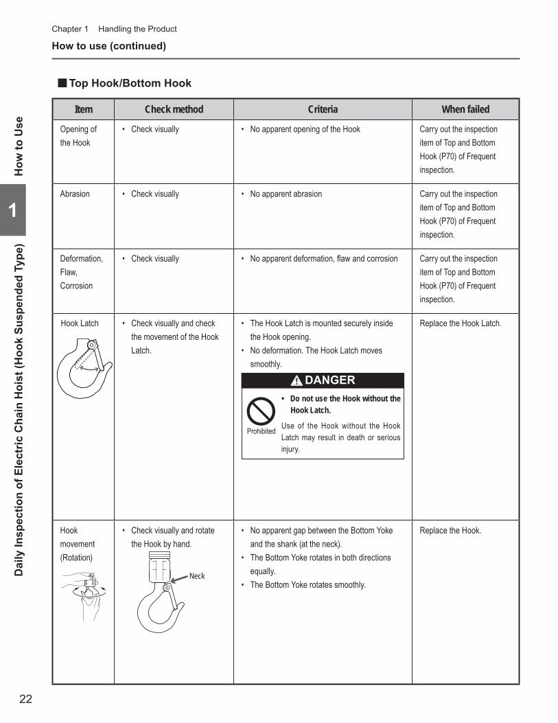
Top Hook/Bottom Hook ■
Item Check method Criteria When failed
Opening of the Hook
Check visually• No apparent opening of the Hook• Carry out the inspection item of Top and Bottom Hook (P70) of Frequent inspection.
Abrasion Check visually• No apparent abrasion• Carry out the inspection item of Top and Bottom Hook (P70) of Frequent inspection.
Deformation, Flaw, Corrosion
Check visually• No apparent deformation, fl aw and corrosion• Carry out the inspection item of Top and Bottom Hook (P70) of Frequent inspection.
Hook Latch Check visually and check • the movement of the Hook Latch.
The Hook Latch is mounted securely inside • the Hook opening. No deformation. The Hook Latch moves • smoothly.
Do not use the Hook without the •Hook Latch.
Use of the Hook without the Hook Latch may result in death or serious injury.
Prohibited
DANGER
Replace the Hook Latch.
Hook movement (Rotation)
Check visually and rotate • the Hook by hand.
Neck
No apparent gap between the Bottom Yoke • and the shank (at the neck). The Bottom Yoke rotates in both directions • equally.The Bottom Yoke rotates smoothly.•
Replace the Hook.
How
to U
seD
aily
Insp
ectio
n of
Ele
ctric
Cha
in H
oist
(Hoo
k Su
spen
ded
Type
)
23
11
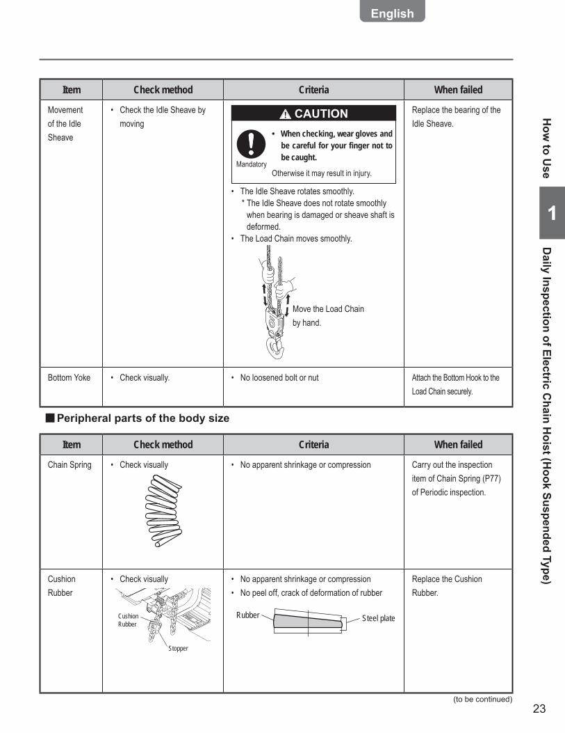
Item Check method Criteria When failed
Movement of the Idle Sheave
Check the Idle Sheave by • moving
When checking, wear gloves and •be careful for your finger not to be caught.
Otherwise it may result in injury.Mandatory
CAUTION
The Idle Sheave rotates smoothly.• * The Idle Sheave does not rotate smoothly
when bearing is damaged or sheave shaft is deformed.
The Load Chain moves smoothly.•
Move the Load Chain by hand.
Replace the bearing of the Idle Sheave.
Bottom Yoke Check visually.• No loosened bolt or nut• Attach the Bottom Hook to the Load Chain securely.
Peripheral parts of the body size ■
Item Check method Criteria When failed
Chain Spring Check visually• No apparent shrinkage or compression• Carry out the inspection item of Chain Spring (P77) of Periodic inspection.
Cushion Rubber
Check visually•
Stopper
Cushion Rubber
No apparent shrinkage or compression• No peel off, crack of deformation of rubber•
Rubber Steel plate
Replace the Cushion Rubber.
(to be continued)
How
to Use
Daily Inspection of Electric C
hain Hoist (H
ook Suspended Type)
24
1
Chapter 1 Handling the Product
How to use (continued)
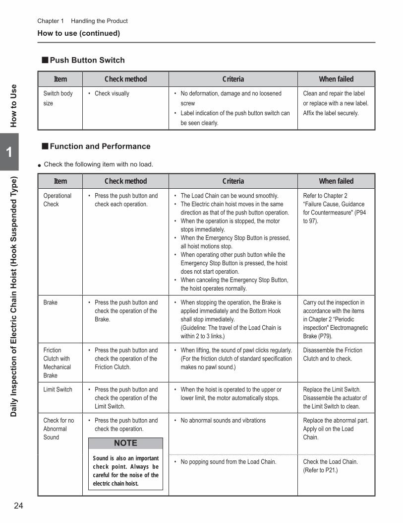
Push Button Switch ■
Item Check method Criteria When failed
Switch body size
Check visually• No deformation, damage and no loosened • screw Label indication of the push button switch can • be seen clearly.
Clean and repair the label or replace with a new label. Affix the label securely.
Function and Performance ■
Item Check method Criteria When failed
Operational Check
Press the push button and • check each operation.
The Load Chain can be wound smoothly.• The Electric chain hoist moves in the same • direction as that of the push button operation. When the operation is stopped, the motor • stops immediately. When the Emergency Stop Button is pressed, • all hoist motions stop. When operating other push button while the • Emergency Stop Button is pressed, the hoist does not start operation. When canceling the Emergency Stop Button, • the hoist operates normally.
Refer to Chapter 2 “Failure Cause, Guidance for Countermeasure" (P94 to 97).
Brake Press the push button and • check the operation of the Brake.
When stopping the operation, the Brake is • applied immediately and the Bottom Hook shall stop immediately. (Guideline: The travel of the Load Chain is within 2 to 3 links.)
Carry out the inspection in accordance with the items in Chapter 2 “Periodic inspection" Electromagnetic Brake (P79).
Friction Clutch with Mechanical Brake
Press the push button and • check the operation of the Friction Clutch.
When lifting, the sound of pawl clicks regularly.• (For the friction clutch of standard specifi cation makes no pawl sound.)
Disassemble the Friction Clutch and to check.
Limit Switch Press the push button and • check the operation of the Limit Switch.
When the hoist is operated to the upper or • lower limit, the motor automatically stops.
Replace the Limit Switch.Disassemble the actuator of the Limit Switch to clean.
Check for no Abnormal Sound
Press the push button and • check the operation.
Sound is also an important check point . Always be careful for the noise of the electric chain hoist.
NOTE
No abnormal sounds and vibrations• Replace the abnormal part.Apply oil on the Load Chain.
No popping sound from the Load Chain.• Check the Load Chain. (Refer to P21.)
Check the following item with no load. ●
How
to U
seD
aily
Insp
ectio
n of
Ele
ctric
Cha
in H
oist
(Hoo
k Su
spen
ded
Type
)
25
11
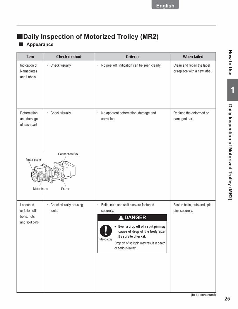
Daily Inspection of Motorized Trolley (MR2) ■Appearance ■
Item Check method Criteria When failed
Indication of Nameplates and Labels
Check visually• No peel off. Indication can be seen clearly.• Clean and repair the label or replace with a new label.
Deformation and damage of each part
Check visually• No apparent deformation, damage and • corrosion
Replace the deformed or damaged part.
Loosened or fallen off bolts, nuts and split pins
Check visually or using • tools.
Bolts, nuts and split pins are fastened • securely.
Even a drop off of a split pin may •cause of drop of the body size. Be sure to check it.
Drop off of split pin may result in death or serious injury.
Mandatory
DANGER
Fasten bolts, nuts and split pins securely.
Connection Box
FrameMotor frame
Motor cover
How
to Use
Daily Inspection of M
otorized Trolley (MR
2)
(to be continued)

26
1
Chapter 1 Handling the Product
How to use (continued)
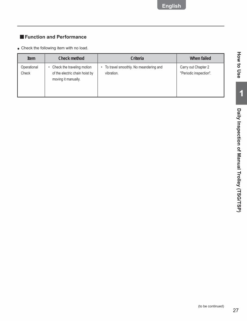
Function and Performance ■
Item Check method Criteria When failed
Operational Check
Press the push button to • check the operation.
To travel smoothly. No meandering and • vibration. The electric chain hoist moves in the same • direction as that of the push button operation. When the operation is stopped, the motor • stops immediately. When the Emergency Stop Button is pressed, • all hoist motions stop. When operating other push button while the • Emergency Stop Button is pressed, the hoist does not start operation. When canceling the Emergency Stop Button, • the hoist operates normally.
Refer to Chapter 2 “Failure Cause, Guidance for Countermeasure" (P94 to 97).
Brake Press the push button to • check the operation of the Brake.
When the operation is stopped, the Brake is • applied and the motor stops immediately.
Carry out the inspection in accordance with the items in Chapter 2 “Periodic inspection" Electromagnetic Brake (P79).
Daily Inspection of Manual Trolley (TSG/TSP) ■Appearance ■
Item Check method Criteria When failed
Indication of Nameplates and Labels
Check visually• No peel off. Indication can be seen clearly.• Clean and repair the label or replace with a new label.
Deformation and damage of each part
Check visually• No apparent deformation and corrosion• No apparent deformation on the Frame•
Replace the deformed or damaged part.
Loosened or fallen off bolts, nuts and split pins
Check visually or using • tools.
Bolts, nuts and split pins are fastened • securely.
Even a drop off of a split pin may •cause of drop of the body size. Be sure to check it.
Drop off of split pin may result in death or serious injury.
Mandatory
DANGER
Fasten bolts, nuts and split pins securely.
Check the following item with no load. ●
How
to U
seDa
ily In
spec
tion
of M
otor
ized
Tro
lley
(MR2
) / D
aily
Insp
ectio
n of
Man
ual T
rolle
y (T
SG/T
SP)
27
11
Function and Performance ■
Item Check method Criteria When failed
Operational Check
Check the traveling motion • of the electric chain hoist by moving it manually.
To travel smoothly. No meandering and • vibration.
Carry out Chapter 2 "Periodic inspection".
Check the following item with no load. ● How
to Use
Daily Inspection of M
anual Trolley (TSG/TSP)
(to be continued)

28
1
Chapter 1 Handling the Product
How to Operate the Push Button Switches ■
Lift/Lower Button ●
Emergency Stop Button (VFD Reset Button) ●
Operation Button ●
1) Press the Emergency Stop Button deeply when carrying out an emergency stop or VFD reset.
The button is locked at the pressed end. •2) Turn the Emergency Stop Button clockwise to cancel the lock.
Press-locked button returns to the original position. •* When the electric chain hoist is not used, press the Emergency Stop Button deeply to the end.
Single Speed Model Dual Speed VFD Model
1) Press button to lift the load.
The electric chain hoist stops •when the button is released.
1) Press button to lift the load.2) When lifting the load at high speed, press the
button further to the end.The electric chain hoist stops when the button is •released.
1) Press button to lower the load.
The electric chain hoist stops •when the button is released.
1) Press button to lower the load.2) When lowering the load at high speed, press the
button further to the end.The electric chain hoist stops when the button is •released.
Do not hang the Push Button Switch Cord on other object, or pull the cord strongly. •Do not use the Push Button Switch if its button does not operate smoothly. •Do not bundle or tie the cord for the adjustment of its length. •
Failure to comply with this instruction causes bodily injury or loss of property.
CAUTION
When taking hand off the Push Button Switch after operation, do not throw it. Be careful not to hit other worker •with the Push Button Switch.
Failure to comply with this instruction causes bodily injury or loss of property.Mandatory
Prohibited
3-Push Button Switch Set ■3-Push Button Switch Set is equipped with a lock type emergency stop button (VFD reset button) and lift/lower push buttons. One-step push button switch or two-step push button switch is mounted as Lift/lower push button switches in accordance with the specification of single speed or dual speed VFD specification. Refer to the operation method of the corresponding specification.
How to use (continued)
NOTEIf the Electric chain hoist is tripped due to overheat of the VFD, the VFD cannot be reset soon after the trip. Reset the VFD after a while.
How
to U
seH
ow to
Ope
rate
the
Push
But
ton
Switc
hes
29
11
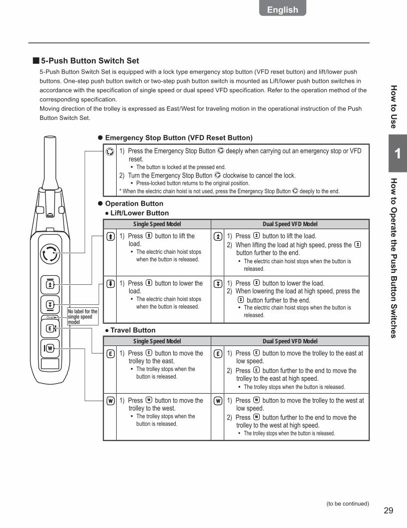
5-Push Button Switch Set ■5-Push Button Switch Set is equipped with a lock type emergency stop button (VFD reset button) and lift/lower push buttons. One-step push button switch or two-step push button switch is mounted as Lift/lower push button switches in accordance with the specification of single speed or dual speed VFD specification. Refer to the operation method of the corresponding specification. Moving direction of the trolley is expressed as East/West for traveling motion in the operational instruction of the Push Button Switch Set.
Lift/Lower Button ●
Travel Button ●
Emergency Stop Button (VFD Reset Button) ●
Operation Button ●
DualNo label for the single speed model
1) Press the Emergency Stop Button deeply when carrying out an emergency stop or VFD reset.
The button is locked at the pressed end. •2) Turn the Emergency Stop Button clockwise to cancel the lock.
Press-locked button returns to the original position. •* When the electric chain hoist is not used, press the Emergency Stop Button deeply to the end.
Single Speed Model Dual Speed VFD Model
1) Press button to move the trolley to the east.
The trolley stops when the •button is released.
1) Press button to move the trolley to the east at low speed.
2) Press button further to the end to move the trolley to the east at high speed.
The trolley stops when the button is released. •
1) Press button to move the trolley to the west.
The trolley stops when the •button is released.
1) Press button to move the trolley to the west at low speed.
2) Press button further to the end to move the trolley to the west at high speed.
The trolley stops when the button is released. •
Single Speed Model Dual Speed VFD Model
1) Press button to lift the load.
The electric chain hoist stops •when the button is released.
1) Press button to lift the load.2) When lifting the load at high speed, press the
button further to the end.The electric chain hoist stops when the button is •released.
1) Press button to lower the load.
The electric chain hoist stops •when the button is released.
1) Press button to lower the load.2) When lowering the load at high speed, press the
button further to the end.The electric chain hoist stops when the button is •released.
How
to Use
How
to Operate the Push B
utton Switches
(to be continued)
30
1
Chapter 1 Handling the Product
Dual
Dual
No label for the single speed model
No label for the single speed model
How to use (continued)
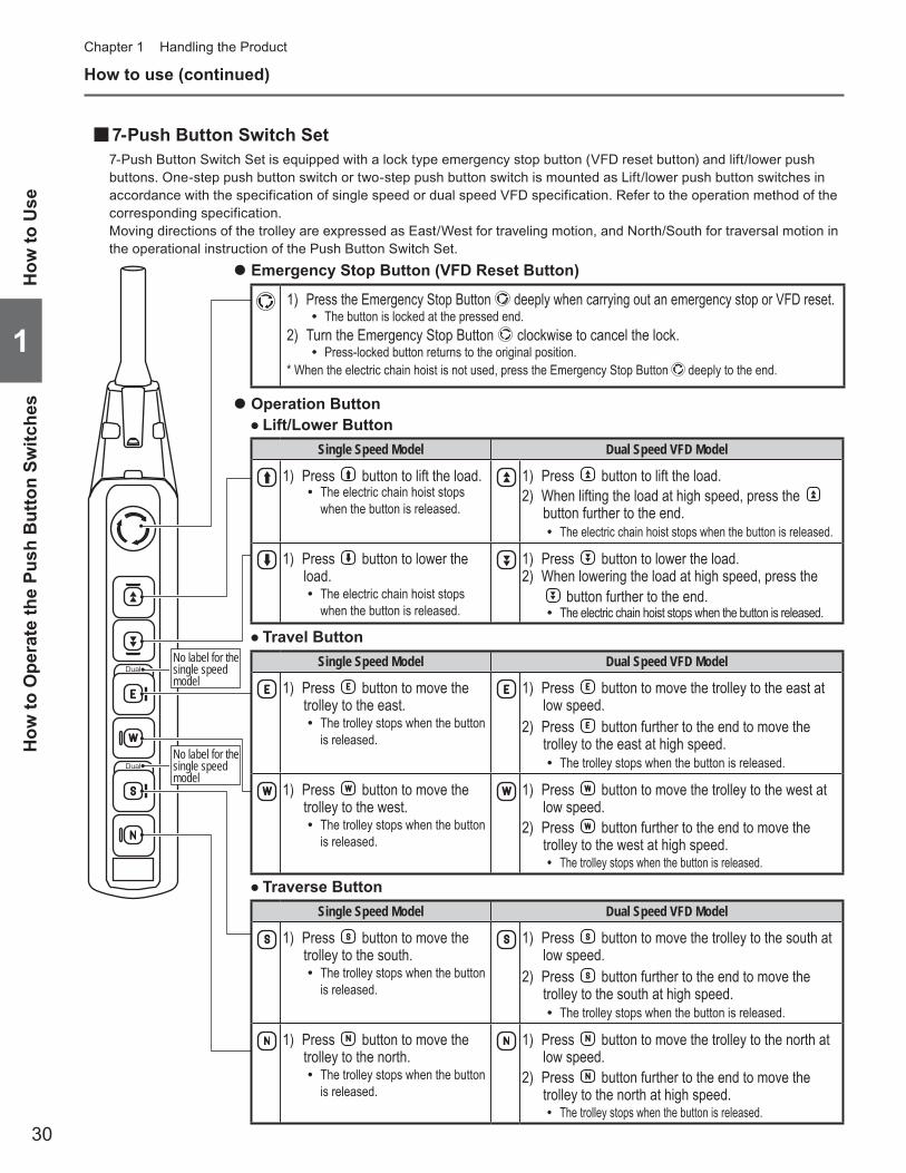
7-Push Button Switch Set ■7-Push Button Switch Set is equipped with a lock type emergency stop button (VFD reset button) and lift/lower push buttons. One-step push button switch or two-step push button switch is mounted as Lift/lower push button switches in accordance with the specification of single speed or dual speed VFD specification. Refer to the operation method of the corresponding specification. Moving directions of the trolley are expressed as East/West for traveling motion, and North/South for traversal motion in the operational instruction of the Push Button Switch Set.
Traverse Button ●
Lift/Lower Button ●
Travel Button ●
Emergency Stop Button (VFD Reset Button) ●
Operation Button ●
Single Speed Model Dual Speed VFD Model
1) Press button to move the trolley to the south.
The trolley stops when the button •is released.
1) Press button to move the trolley to the south at low speed.
2) Press button further to the end to move the trolley to the south at high speed.
The trolley stops when the button is released. •
1) Press button to move the trolley to the north.
The trolley stops when the button •is released.
1) Press button to move the trolley to the north at low speed.
2) Press button further to the end to move the trolley to the north at high speed.
The trolley stops when the button is released. •
Single Speed Model Dual Speed VFD Model
1) Press button to move the trolley to the east.
The trolley stops when the button •is released.
1) Press button to move the trolley to the east at low speed.
2) Press button further to the end to move the trolley to the east at high speed.
The trolley stops when the button is released. •
1) Press button to move the trolley to the west.
The trolley stops when the button •is released.
1) Press button to move the trolley to the west at low speed.
2) Press button further to the end to move the trolley to the west at high speed.
The trolley stops when the button is released. •
1) Press the Emergency Stop Button deeply when carrying out an emergency stop or VFD reset.The button is locked at the pressed end. •
2) Turn the Emergency Stop Button clockwise to cancel the lock.Press-locked button returns to the original position. •
* When the electric chain hoist is not used, press the Emergency Stop Button deeply to the end.
Single Speed Model Dual Speed VFD Model
1) Press button to lift the load.The electric chain hoist stops •when the button is released.
1) Press button to lift the load.2) When lifting the load at high speed, press the
button further to the end.The electric chain hoist stops when the button is released. •
1) Press button to lower the load.
The electric chain hoist stops •when the button is released.
1) Press button to lower the load.2) When lowering the load at high speed, press the
button further to the end.The electric chain hoist stops when the button is released. •
How
to U
seH
ow to
Ope
rate
the
Push
But
ton
Switc
hes
31
11
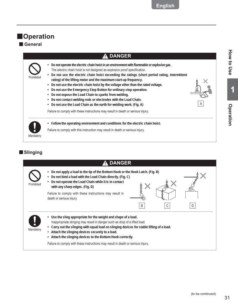
Operation ■General ■
Do not operate the electric chain hoist in an environment with flammable or explosive gas. •The electric chain hoist is not designed as explosion proof specification.Do not use the electric chain hoist exceeding the ratings (short period rating, intermittent •rating) of the lifting motor and the maximum start-up frequency.Do not use the electric chain hoist by the voltage other than the rated voltage. •Do not use the Emergency Stop Button for ordinary stop operation. •Do not expose the Load Chain to sparks from welding. •Do not contact welding rods or electrodes with the Load Chain. •Do not use the Load Chain as the earth for welding work. (Fig. A) •
Failure to comply with these instructions may result in death or serious injury.
Prohibited
A
Follow the operating environment and conditions for the electric chain hoist. •
Failure to comply with this instruction may result in death or serious injury.Mandatory
Slinging ■
Do not apply a load to the tip of the Bottom Hook or the Hook Latch. (Fig. B) •Do not bind a load with the Load Chain directly. (Fig. C) •Do not operate the Load Chain while it is in contact •with any sharp edges. (Fig. D)
Failure to comply with these instructions may result in death or serious injury.
Prohibited
Use the sling appropriate for the weight and shape of a load. •Inappropriate slinging may result in danger such as drop of a lifted load.Carry out the slinging with equal load on slinging devices for stable lifting of a load. •Attach the slinging devices securely to a load. •Attach the slinging devices to the Bottom Hook correctly. •
Failure to comply with these instructions may result in death or serious injury.
Mandatory
CB D
How
to Use
Operation
(to be continued)
DANGER
DANGER
32
1
Chapter 1 Handling the Product
How to use (continued)
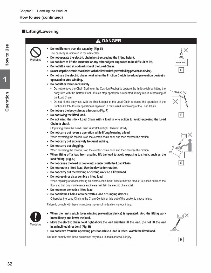
Lifting/Lowering ■
Do not lift more than the capacity. (Fig. E) •The capacity is indicated in the nameplate.Do not operate the electric chain hoist exceeding the lifting height. •Do not dare to lift the structure or any other object supposed to be difficult to lift. •Do not lift a load at no-load side of the Load Chain. •Do not stop the electric chain hoist with the limit switch (over winding prevention device). •Do not use the electric chain hoist when the Friction Clutch (overload prevention device) is •operated to stop winding.Do not lift or lower excessively. •
Do not remove the Chain Spring or the Cushion Rubber to operate the limit switch by hitting the •body size with the Bottom Hook. If such stop operation is repeated, it may result in breaking of the Load Chain. Do not hit the body size with the End Stopper of the Load Chain to cause the operation of the •Friction Clutch. If such operation is repeated, it may result in breaking of the Load Chain.
Do not use the body size as a fulcrum. (Fig. F) •Do not swing the lifted load. •Do not wind the slack Load Chain with a load in one action to avoid exposing the Load •Chain to shock.Stop lifting when the Load Chain is stretched tight. Then lift slowly.Do not carry out reverse operation while lifting/lowering a load. •When reversing the motion, stop the electric chain hoist and then reverse the motion.Do not carry out excessively frequent inching. •Do not carry out plugging. •When reversing the motion, stop the electric chain hoist and then reverse the motion.When lifting off a load from a pallet, lift the load to avoid exposing to shock, such as the •load falling. (Fig. G)Do not cause the load to come into contact with the Load Chain. •Do not rotate a lifted load. Use the device for rotation. •Do not carry out the welding or cutting work on a lifted load. •Do not repair or disassemble a lifted load. •When repairing or disassembling an electric chain hoist, ensure that the product is placed down on the floor and that only maintenance engineers maintain the electric chain hoist.Do not enter beneath a lifted load. •Do not hit the Chain Container with a load or slinging devices. •Otherwise the Load Chain in the Chain Container falls out of the bucket to cause injury.
Failure to comply with these instructions may result in death or serious injury.
Prohibited
When the limit switch (over winding prevention device) is operated, stop the lifting work •immediately and lower the load.Move the electric chain hoist right above the load and then lift the load. (Do not lift the load •in an inclined direction.) (Fig. H)Do not leave from the operating position while a load is lifted. Watch the lifted load. •
Failure to comply with these instructions may result in death or serious injury.
Mandatory
over load
E
F
G
H
How
to U
seO
pera
tion
DANGER
33
11
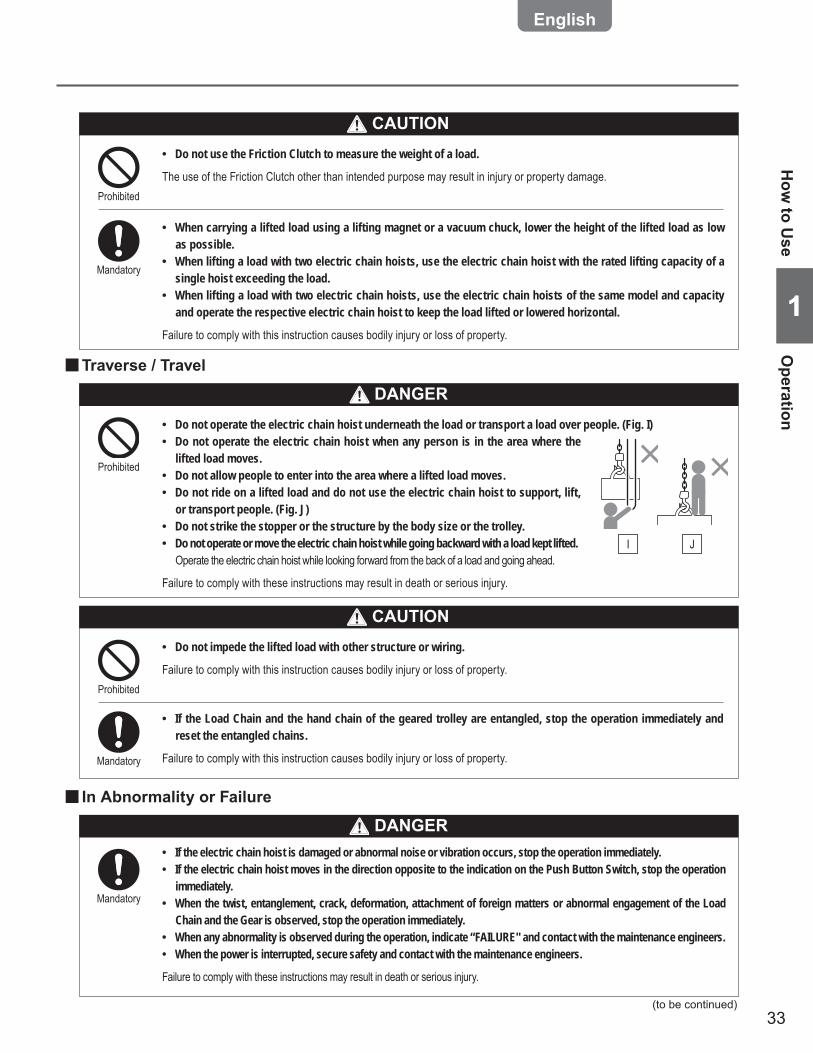
Do not use the Friction Clutch to measure the weight of a load. •
The use of the Friction Clutch other than intended purpose may result in injury or property damage.Prohibited
When carrying a lifted load using a lifting magnet or a vacuum chuck, lower the height of the lifted load as low •as possible.When lifting a load with two electric chain hoists, use the electric chain hoist with the rated lifting capacity of a •single hoist exceeding the load.When lifting a load with two electric chain hoists, use the electric chain hoists of the same model and capacity •and operate the respective electric chain hoist to keep the load lifted or lowered horizontal.
Failure to comply with this instruction causes bodily injury or loss of property.
Mandatory
CAUTION
In Abnormality or Failure ■
If the electric chain hoist is damaged or abnormal noise or vibration occurs, stop the operation immediately. •If the electric chain hoist moves in the direction opposite to the indication on the Push Button Switch, stop the operation •immediately.When the twist, entanglement, crack, deformation, attachment of foreign matters or abnormal engagement of the Load •Chain and the Gear is observed, stop the operation immediately.When any abnormality is observed during the operation, indicate “FAILURE" and contact with the maintenance engineers. •When the power is interrupted, secure safety and contact with the maintenance engineers. •
Failure to comply with these instructions may result in death or serious injury.
Mandatory
Do not impede the lifted load with other structure or wiring. •
Failure to comply with this instruction causes bodily injury or loss of property.Prohibited
If the Load Chain and the hand chain of the geared trolley are entangled, stop the operation immediately and •reset the entangled chains.
Failure to comply with this instruction causes bodily injury or loss of property.Mandatory
CAUTION
Traverse / Travel ■
Do not operate the electric chain hoist underneath the load or transport a load over people. (Fig. I) •Do not operate the electric chain hoist when any person is in the area where the •lifted load moves.Do not allow people to enter into the area where a lifted load moves. •Do not ride on a lifted load and do not use the electric chain hoist to support, lift, •or transport people. (Fig. J)Do not strike the stopper or the structure by the body size or the trolley. •Do not operate or move the electric chain hoist while going backward with a load kept lifted. •Operate the electric chain hoist while looking forward from the back of a load and going ahead.
Failure to comply with these instructions may result in death or serious injury.
Prohibited
I J
How
to Use
Operation
(to be continued)
DANGER
DANGER
34
1
Chapter 1 Handling the Product
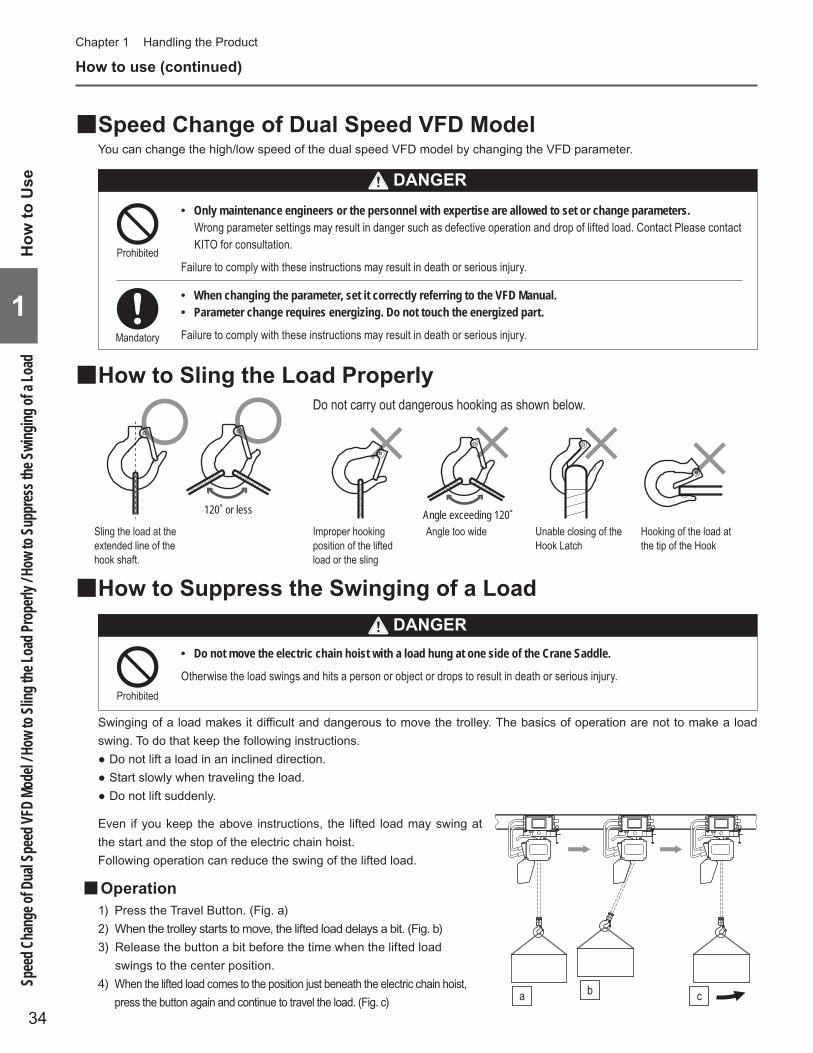
Angle exceeding 120˚120˚ or less
Do not carry out dangerous hooking as shown below.
Sling the load at the extended line of the hook shaft.
Improper hooking position of the lifted load or the sling
Angle too wide Unable closing of the Hook Latch
Hooking of the load at the tip of the Hook
How to Sling the Load Properly ■
How to Suppress the Swinging of a Load ■
Do not move the electric chain hoist with a load hung at one side of the Crane Saddle. •
Otherwise the load swings and hits a person or object or drops to result in death or serious injury.Prohibited
Swinging of a load makes it difficult and dangerous to move the trolley. The basics of operation are not to make a load swing. To do that keep the following instructions.
Do not lift a load in an inclined direction. ●Start slowly when traveling the load. ●Do not lift suddenly. ●
Even if you keep the above instructions, the lifted load may swing at the start and the stop of the electric chain hoist.Following operation can reduce the swing of the lifted load.
Operation ■1) Press the Travel Button. (Fig. a)2) When the trolley starts to move, the lifted load delays a bit. (Fig. b)3) Release the button a bit before the time when the lifted load
swings to the center position.4) When the lifted load comes to the position just beneath the electric chain hoist,
press the button again and continue to travel the load. (Fig. c)ba c
How to use (continued)
Speed Change of Dual Speed VFD Model ■You can change the high/low speed of the dual speed VFD model by changing the VFD parameter.
Only maintenance engineers or the personnel with expertise are allowed to set or change parameters. •Wrong parameter settings may result in danger such as defective operation and drop of lifted load. Contact Please contact KITO for consultation.
Failure to comply with these instructions may result in death or serious injury.
Mandatory
Prohibited
When changing the parameter, set it correctly referring to the VFD Manual. •Parameter change requires energizing. Do not touch the energized part. •
Failure to comply with these instructions may result in death or serious injury.
How
to U
seSp
eed C
hang
e of D
ual S
peed
VFD
Mode
l / Ho
w to
Sling
the L
oad P
rope
rly / H
ow to
Supp
ress t
he Sw
inging
of a
Load
DANGER
DANGER
35
11
Prohibited
CAUTIONDo not store the electric chain hoist at a state of over lifting or over lowering. •
Failure to comply with these instructions causes bodily injury or loss of property.
NOTEClean the push buttons always not to allow the dust and sands attach. •When storing the electric chain hoist for a long period, it is effective to prevent rusting to operate it at a certain period without •load.When putting the electric chain hoist on a floor, remove the Chain Container. •Otherwise the Chain Container may deform or be damaged.When not using the electric chain hoist, wind up the Bottom Hook to the height not to hinder persons passing by or other work. •Decide the place to store the electric chain hoist in advance. It is recommended to hang the push button set on the pillar. •
Precautions After Work ■
Store the electric chain hoist with power off. •Indicate “FAILURE" on the electric chain hoist that needs repair not to be used. •Wipe off dust and waterdrop, apply oil at the neck of the Hook and the Load Chain and store the hoist. •Remove the stain, attached foreign matter and waterdrop from the parts such as the Limit Switch and the Chain •Container that is scratched by the Load Chain or stored it.When the electric chain hoist is installed outdoor, cover it with rain cover or roof after application of rust proof •process.
Failure to comply with these instructions causes bodily injury or loss of property.
Mandatory
How
to Use
Precautions After W
ork
36
1
Chapter 1 Handling the Product
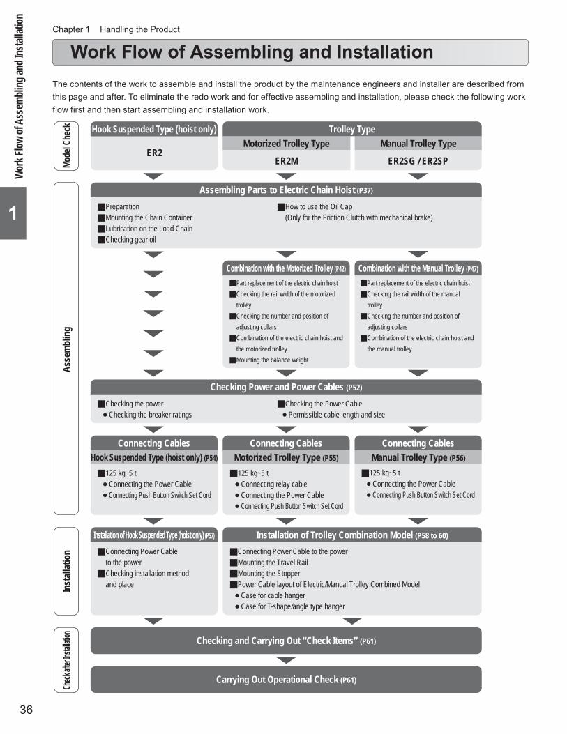
Work Flow of Assembling and InstallationThe contents of the work to assemble and install the product by the maintenance engineers and installer are described from this page and after. To eliminate the redo work and for effective assembling and installation, please check the following work flow first and then start assembling and installation work.
Mode
l Che
ckAs
sem
blin
gIn
stall
atio
nCh
eck aft
er Inst
allation
Hook Suspended Type (hoist only) Trolley Type
Installation of Hook Suspended Type (hoist only) (P57) Installation of Trolley Combination Model (P58 to 60)
Assembling Parts to Electric Chain Hoist (P37)
Checking Power and Power Cables (P52)
Combination with the Motorized Trolley (P42) Combination with the Manual Trolley (P47)
Motorized Trolley Type Manual Trolley Type
Connecting Cables Connecting Cables Connecting Cables
PreparationMounting the Chain ContainerLubrication on the Load ChainChecking gear oil
Connecting Power Cable to the powerMounting the Travel RailMounting the StopperPower Cable layout of Electric/Manual Trolley Combined Model Case for cable hanger Case for T-shape/angle type hanger
Connecting Power Cable to the power
Checking installation method and place
125 kg~5 t Connecting relay cable Connecting the Power Cable Connecting Push Button Switch Set Cord
125 kg~5 t Connecting the Power Cable Connecting Push Button Switch Set Cord
How to use the Oil Cap(Only for the Friction Clutch with mechanical brake)
Checking the power Checking the breaker ratings
Checking the Power Cable Permissible cable length and size
Checking and Carrying Out “Check Items” (P61)
ER2MER2
ER2SG / ER2SP
Carrying Out Operational Check (P61)
Motorized Trolley Type (P55)
125 kg~5 t Connecting the Power Cable Connecting Push Button Switch Set Cord
Hook Suspended Type (hoist only) (P54) Manual Trolley Type (P56)
Part replacement of the electric chain hoistChecking the rail width of the motorized
trolleyChecking the number and position of
adjusting collarsCombination of the electric chain hoist and
the motorized trolleyMounting the balance weight
Part replacement of the electric chain hoistChecking the rail width of the manual
trolleyChecking the number and position of
adjusting collarsCombination of the electric chain hoist and
the manual trolley
Work
Flow
of As
semb
ling a
nd In
stalla
tion

37
11
The each type of Chain Container has the capacity to store the specific amount of the Load Chain. Use correct •capacity of the Chain Container.When storing the Load Chain of which amount exceeds the capacity of the Chain Container, it may result in death or serious injury due to the flow over of the Load Chain from the Chain Container or defective operation of the electric chain hoist.Improper combination of the Chain Container and the electric chain hoist is very dangerous because of the possibility of drop of the Chain Container.The seal to indicate the capacity and lifting height is attached on the Chain Container. Check it before use.If the Chain Container is not assembled correctly, it may result in death or serious injury due to a drop of the •Chain Container or Load Chain, and malfunction of the Electric Chain Hoist. Refer to the assembling instruction on the page 38 and assemble the Chain Container correctly.
Failure to comply with these instructions causes bodily injury or loss of property.
Mandatory
Assembling
Only maintenance engineers or the personnel with expertise are allowed to assemble and disassemble the electric •chain hoist.
Assembling or disassembling of the electric chain hoist may result in death or serious injury.Prohibited
Assembling Parts to Electric Chain Hoist ■Preparation for Assembling ■
Hang the electric chain hoist body size to facilitate the mounting of the Chain Container.* Check that the stopper and the cushion rubber are mounted at the link third from the no load side of the Load Chain * (the end without the Bottom Hook).
Mounting the Chain Container ■The three types of the Chain Container are provided: bucket made of plastic, canvas and steelThis manual describes the method to combine the plastic or canvas Chain Container with the body size of the electric chain hoist. Refer to the separate “Mounting Manual of the Steel Chain Container" for the steel Chain Container.
When storing the Load Chain into the Chain Container, put the chain end with no-load side first and then store •the rest of the Load Chain.
Failure to comply with these instructions causes bodily injury or loss of property.Mandatory
CAUTION
Assem
blingA
ssembling Parts to Electric C
hain Hoist
(to be continued)
DANGER
DANGER
38
1
Chapter 1 Handling the Product
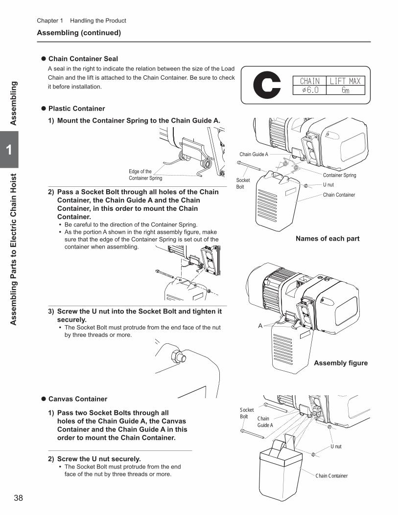
Chain Container Seal ●
A seal in the right to indicate the relation between the size of the Load Chain and the lift is attached to the Chain Container. Be sure to check it before installation.
Plastic Container ●
1) Mount the Container Spring to the Chain Guide A.
2) Pass a Socket Bolt through all holes of the Chain Container, the Chain Guide A and the Chain Container, in this order to mount the Chain Container.
Be careful to the direction of the Container Spring. •As the portion A shown in the right assembly figure, make •sure that the edge of the Container Spring is set out of the container when assembling.
3) Screw the U nut into the Socket Bolt and tighten it securely.
The Socket Bolt must protrude from the end face of the nut •by three threads or more.
Socket Bolt
Container Spring
Chain Guide A
U nut
Chain Container
Assembling (continued)
Canvas Container ●
1) Pass two Socket Bolts through all holes of the Chain Guide A, the Canvas Container and the Chain Guide A in this order to mount the Chain Container.
2) Screw the U nut securely.The Socket Bolt must protrude from the end •face of the nut by three threads or more.
SocketBolt
U nut
Chain Container
ChainGuide A
Ass
embl
ing
Ass
embl
ing
Part
s to
Ele
ctric
Cha
in H
oist
A
Edge of the Container Spring
Names of each part
Assembly figure
39
11
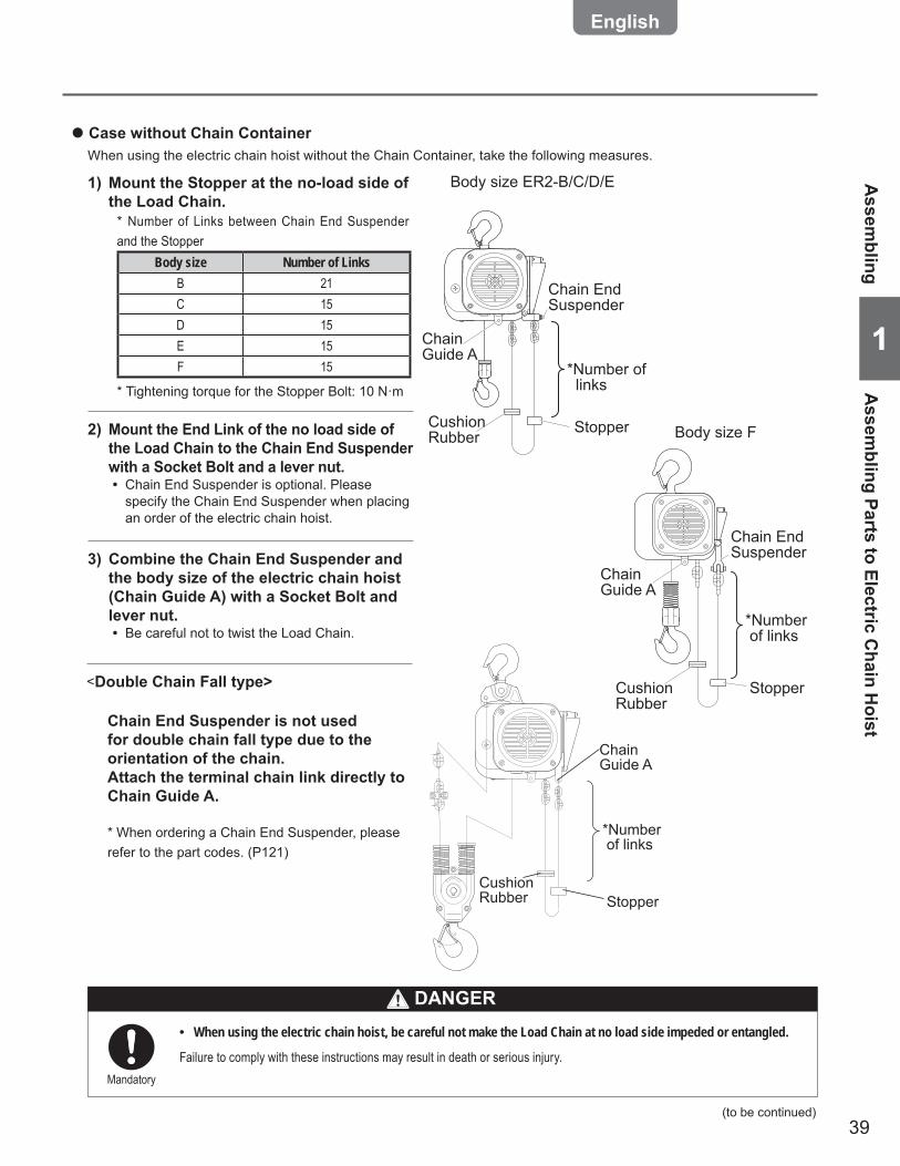
Case without Chain Container ●
When using the electric chain hoist without the Chain Container, take the following measures.
2) Mount the End Link of the no load side of the Load Chain to the Chain End Suspender with a Socket Bolt and a lever nut.
Chain End Suspender is optional. Please •specify the Chain End Suspender when placing an order of the electric chain hoist.
3) Combine the Chain End Suspender and the body size of the electric chain hoist (Chain Guide A) with a Socket Bolt and lever nut.
Be careful not to twist the Load Chain. •
1) Mount the Stopper at the no-load side of the Load Chain.
* Number of Links between Chain End Suspender and the Stopper
Body size Number of LinksB 21C 15D 15E 15F 15
* Tightening torque for the Stopper Bolt: 10 N·m
When using the electric chain hoist, be careful not make the Load Chain at no load side impeded or entangled. •
Failure to comply with these instructions may result in death or serious injury.Mandatory
(to be continued)
Assem
blingA
ssembling Parts to Electric C
hain Hoist
DANGER
<Double Chain Fall type>
Chain End Suspender is not used for double chain fall type due to the orientation of the chain.Attach the terminal chain link directly to Chain Guide A.
* When ordering a Chain End Suspender, please refer to the part codes. (P121)
Body size ER2-B/C/D/E
Body size F
Chain End Suspender
Chain Guide A
Cushion Rubber
*Number of links
Stopper
Chain Guide A
Chain End Suspender
Stopper
*Number of links
Cushion Rubber
*Number of links
StopperCushion Rubber
Chain Guide A

40
1
Chapter 1 Handling the Product
Assembling (continued)
Oiling the Load Chain ■
Gear Oil ■Inside of the Gear Case is filled with gear oil at the shipping. The level of the oil filled with specified amount comes to the height of the inspection hole. Check the oil level visually.
Cheking the Gear Oil Amount ●
1) ER2 Body size B/C/D: Remove the Oil Plug on the Main Body at the opposite side of the Chain Container.
ER2 Body size E/F: Remove the Oil Plug on the Main Body at the same side of the Chain Container.
2) If the oil level can be seen close to the inspection hole, the oil amount is normal.
Be sure to apply lubricant on the Load Chain. Do not carry out oiling work in the place near the fire or arc. •
Otherwise it will result in fire.Mandatory
Set the body size to a level and then check the level of gear oil. •
When removing the oil plug without leveling the electric chain hoist, the gear oil flows out. It will result in death or serious injury due to fall by slippery floor.Mandatory
Use genuine gear oil. •
Use of the gear oil other than the genuine oil (including mixed use) will result in death or serious injury due to the drop of the lifted load.Mandatory
Load
Applied position
Remove dust and waterdrops attached on the Load Chain and then apply lubricant. Application of lubricant influences on the life of the Load Chain considerably. Apply the lubricant sufficiently.Use the following genuine lubricant.
Epinoc Grease AP (N)0 (Nippon Oil Corporation) •Consistency No.0 (Industrial general lithium grease) •
Release all loads from the Load Chain. Apply the lubricant to the linking portion of the Load Chain that engages the Load Sheave and the Idle Sheave (hatched area).After application of the lubricant lift/lower the electric chain hoist without load to spread the lubricant on the Load Chain.
Oil Plug
Inspection Hole
Inspection Hole
Oil Plug
Inspection Hole
Body size ER2-E/FBody size ER2-B/C/D
Ass
embl
ing
Ass
embl
ing
Part
s to
Ele
ctric
Cha
in H
oist
DANGER
DANGER
41
11
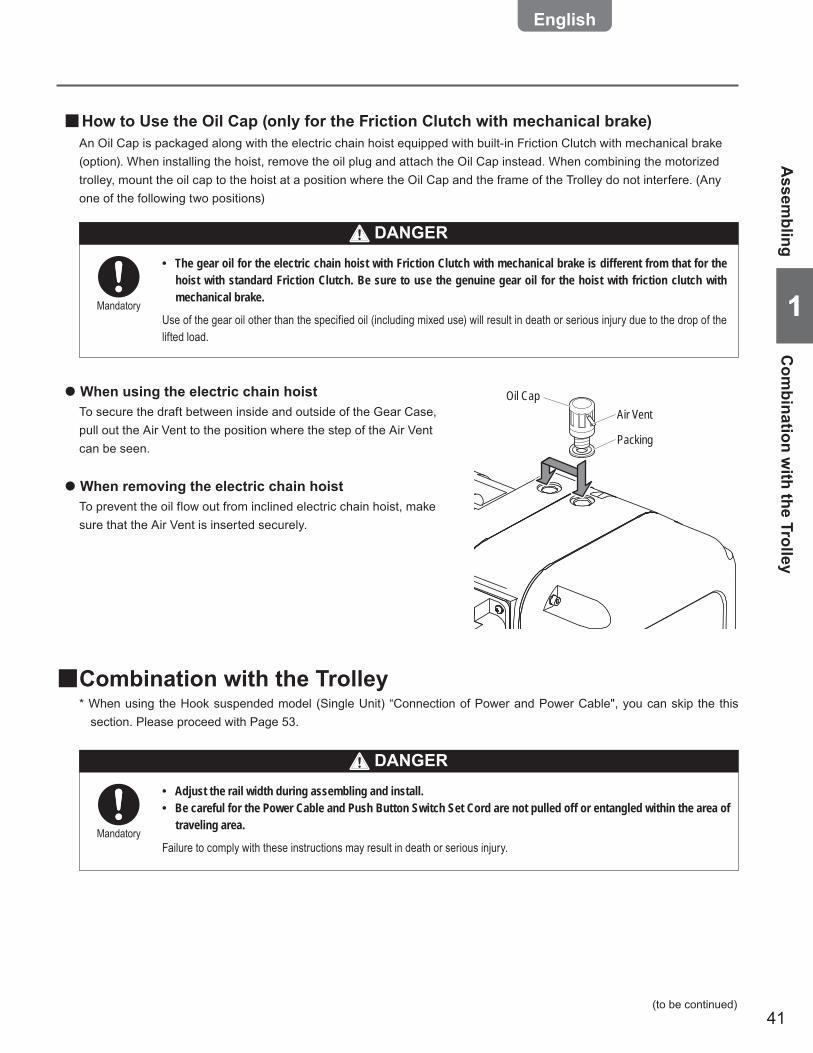
How to Use the Oil Cap (only for the Friction Clutch with mechanical brake) ■An Oil Cap is packaged along with the electric chain hoist equipped with built-in Friction Clutch with mechanical brake (option). When installing the hoist, remove the oil plug and attach the Oil Cap instead. When combining the motorized trolley, mount the oil cap to the hoist at a position where the Oil Cap and the frame of the Trolley do not interfere. (Any one of the following two positions)
Air VentOil Cap
Packing
The gear oil for the electric chain hoist with Friction Clutch with mechanical brake is different from that for the •hoist with standard Friction Clutch. Be sure to use the genuine gear oil for the hoist with friction clutch with mechanical brake.
Use of the gear oil other than the specified oil (including mixed use) will result in death or serious injury due to the drop of the lifted load.
Mandatory
When using the electric chain hoist ●
To secure the draft between inside and outside of the Gear Case, pull out the Air Vent to the position where the step of the Air Vent can be seen.
When removing the electric chain hoist ●
To prevent the oil flow out from inclined electric chain hoist, make sure that the Air Vent is inserted securely.
Combination with the Trolley ■* When using the Hook suspended model (Single Unit) “Connection of Power and Power Cable", you can skip the this
section. Please proceed with Page 53.
Adjust the rail width during assembling and install. •Be careful for the Power Cable and Push Button Switch Set Cord are not pulled off or entangled within the area of •traveling area.
Failure to comply with these instructions may result in death or serious injury.Mandatory
(to be continued)
Assem
blingC
ombination w
ith the Trolley
DANGER
DANGER

42
1
Chapter 1 Handling the Product
Assembling (continued)
Combining with the Motorized Trolley ■
Replacing the Top Hook of Body size ER2-B/C/D/E ●
1) Remove the Shaft Retainer Clip using plier.
6) Mount the Shaft Retainer with Socket Bolt.
5) Insert two Connection Shafts into the hole of the Body size.
4) Remove the Top Hook and replace it with the Suspender T.
3) Remove two Connection Shafts.
2) Remove the Socket Bolt from the Shaft Retainer, and remove the Shaft Retainer.
Replacing the Top Hook of Body size ER2-F ●
1) Remove four Socket Bolts and remove the Controller Cover.
2) Remove pan head screws of the Connection Shaft and the Fixing Shaft (two screws each), and remove the Shaft Retainer.
3) Pinch the respective upper ends of the Connection Shaft and the Fixing Shaft and pull out them.
4) Remove the Top Hook and replace it with the Suspender T.
5) Insert the Connection Shaft and Fixing Shaft into the mounting hole.
6) Fix the Shaft Retainer of the Connection Shaft and the Fixing Shaft with pan head screws (two screws each).
7) Mount the Controller Cover with four pan head screws.
Connection ShaftShaft Retainer
Shaft Retainer Clip
Suspender T
Suspender T
Connection Shaft
Bracing Shaft
Controller Cover
Socket Bolt
O ring
O ringShaft Retainer
Shaft Retainer
Pan Head Screw
Pan Head Screw
Panel
Top Hook
Socket Bolt
Top Hook
For Double Chain Type
For Double Chain Type
CAUTIONWhen using ER2 series electric chain hoist combined with our old type product, specification needs to be •changed. Contact your nearest dealer or KITO.
Parts replacement of the electric chain hoist ■The Suspender is attached to the electric chain hoist at shipping.Refer to the following figure to remove the Top Hook and replace the Suspender with the Suspender T.
Prohibited
Ass
embl
ing
Com
bini
ng w
ith th
e m
otor
ized
trol
ley
43
11
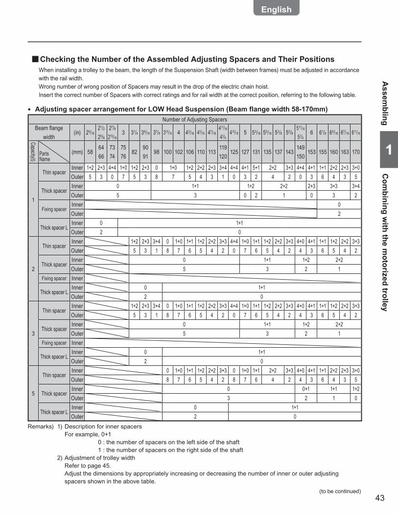
Checking the Number of the Assembled Adjusting Spacers and Their Positions ■When installing a trolley to the beam, the length of the Suspension Shaft (width between frames) must be adjusted in accordance with the rail width.Wrong number of wrong position of Spacers may result in the drop of the electric chain hoist.Insert the correct number of Spacers with correct ratings and for rail width at the correct position, referring to the following table.
(to be continued)
Assem
blingC
ombining w
ith the motorized trolley
Number of Adjusting SpacersBeam flange
width(in) 25/16
21/225/8
27/8215/16
3 31/4 39/16 37/8 315/16 4 43/16 45/16 47/16411/16
43/4415/16 5 53/16 55/16 53/8 55/8
511/16
53/46 61/8 65/16 67/16 611/16
Capacity(t)
PartsName
(mm) 586466
7374
7576
829091
98 100 102 106 110 113119120
125 127 131 135 137 143149150
153 155 160 163 170
1
Thin spacerInner 1+2 2+3 4+4 1+0 1+2 2+3 0 1+0 1+2 2+2 2+3 3+4 4+4 4+1 5+1 2+2 3+3 4+4 4+1 1+1 2+2 2+3 3+0Outer 5 3 0 7 5 3 8 7 5 4 3 1 0 3 2 4 2 0 3 6 4 3 5
Thick spacerInner 0 1+1 1+2 2+2 2+3 3+3 3+4Outer 5 3 0 2 1 0 3 2
Fixing spacerInner 0Outer 2
Thick spacer LInner 0 1+1Outer 2 0
2
Thin spacerInner 1+2 2+3 3+4 0 1+0 1+1 1+2 2+2 3+3 4+4 1+0 1+1 1+2 2+2 3+3 4+0 4+1 1+1 1+2 2+2 3+3Outer 5 3 1 8 7 6 5 4 2 0 7 6 5 4 2 4 3 6 5 4 2
Thick spacerInner 0 1+1 1+2 2+2Outer 5 3 2 1
Fixing spacer Inner
Thick spacer LInner 0 1+1Outer 2 0
3
Thin spacerInner 1+2 2+3 3+4 0 1+0 1+1 1+2 2+2 3+3 4+4 1+0 1+1 1+2 2+2 3+3 4+0 4+1 1+1 1+2 2+2 3+3Outer 5 3 1 8 7 6 5 4 2 0 7 6 5 4 2 4 3 6 5 4 2
Thick spacerInner 0 1+1 1+2 2+2Outer 5 3 2 1
Fixing spacer Inner
Thick spacer LInner 0 1+1Outer 2 0
5
Thin spacerInner 0 1+0 1+1 1+2 2+2 3+3 0 1+0 1+1 2+2 3+3 4+0 4+1 1+1 2+2 2+3 3+0Outer 8 7 6 5 4 2 8 7 6 4 2 4 3 6 4 3 5
Thick spacerInner 0 0+1 1+1 1+2Outer 3 2 1 0
Thick spacer LInner 0 1+1Outer 2 0
Adjusting spacer arrangement for LOW Head Suspension (Beam flange width 58-170mm) ●
Remarks) 1) Description for inner spacers For example, 0+1 0 : the number of spacers on the left side of the shaft 1 : the number of spacers on the right side of the shaft 2) Adjustment of trolley width Refer to page 45. Adjust the dimensions by appropriately increasing or decreasing the number of inner or outer adjusting
spacers shown in the above table.

44
1
Chapter 1 Handling the Product
Number of Adjusting SpacersBeam flange
width(in) 67/8 7
71/16
71/871/475/16
77/8 8 87/16 811/16 9 91/8 97/8 10 101/8 101/4 103/8 101/2 11 111/8 111/4 113/8 115/8 113/4 1113/16 117/8 12
Capacity(t)
PartsName
(mm) 175 178180181
184185
200 203 215 220 229 232 250 254 257 260 264 267 279 283 286 289 295 298 300 302 305
1
Thin spacerInner 4+4 4+1 1+1 1+2 4+4 5+0 2+3 3+4 1+1 1+2 4+0 1+1 1+2 2+2 2+3 3+3 1+1 1+2 2+2 2+3 3+0 4+0 4+1 4+2Outer 0 3 6 5 0 3 3 1 6 5 4 6 5 4 3 2 6 5 4 3 5 4 3 2
Thick spacerInner 3+3 3+4 0 0+1 1+1 2+2 2+3 3+3 4+4 4+5Outer 3 2 9 8 7 5 4 3 1 0
Fixing spacerInner 0 1+1Outer 2 0
Thick spacer LInner 1+1Outer 0
2
Thin spacerInner 4+4 1+4 1+1 1+2 4+4 1+0 2+3 3+3 4+1 1+1 4+4 4+1 5+1 4+3 2+3 3+3 4+1 1+2 2+2 2+3 3+3 3+4 4+4 4+1 5+1Outer 0 3 6 5 0 7 3 2 3 6 0 3 2 1 3 2 3 5 4 3 2 1 0 3 2
Thick spacerInner 2+2 3+2 0 1+1 1+2 2+2 2+3 3+3 3+4 4+4 4+5Outer 1 0 9 7 6 5 4 3 2 1 0
Fixing spacer Inner 1+1
Thick spacer LInner 1+1Outer 0
3
Thin spacerInner 4+4 1+4 1+1 1+2 4+4 1+0 2+3 3+3 4+1 1+1 4+4 4+1 5+1 4+3 2+3 3+3 4+1 1+2 2+2 2+3 3+3 3+4 4+4 4+1 5+1Outer 0 3 6 5 0 7 3 2 3 6 0 3 2 1 3 2 3 5 4 3 2 1 0 3 2
Thick spacerInner 2+2 3+2 0 1+1 1+2 2+2 2+3 3+3 3+4 4+4 4+5Outer 1 0 9 7 6 5 4 3 2 1 0
Fixing spacer Inner 1+1
Thick spacer LInner 1+1Outer 0
5
Thin spacerInner 4+4 4+1 5+1 4+3 4+4 1+0 2+3 3+4 1+1 1+2 4+4 1+1 1+2 2+2 2+3 3+3 5+1 1+2 2+2 2+3 4+3 4+4 4+0 4+1 5+1Outer 0 3 2 1 0 7 3 1 6 5 0 6 5 4 3 2 5 4 3 1 0 4 3 2
Thick spacerInner 1+1 1+2 2+2 3+3 4+4 5+5 5+6 6+6 6+7Outer 1 0 10 9 7 5 3 2 1 0
Thick spacer LInner 1+1Outer 0
Assembling (continued)
Ass
embl
ing
Com
bini
ng w
ith th
e m
otor
ized
trol
ley
Remarks) 3) Thin Spacer arrangement example
Inner
Side plate S
Suspension shaft
Outer
Suspender T
Thick spacer L
Fixing spacer
Side plate G
Thin spacer
Thick spacer
Left side Right side
Adjusting spacer arrangement for LOW Head Suspension (Beam flange width 175-305mm) ●
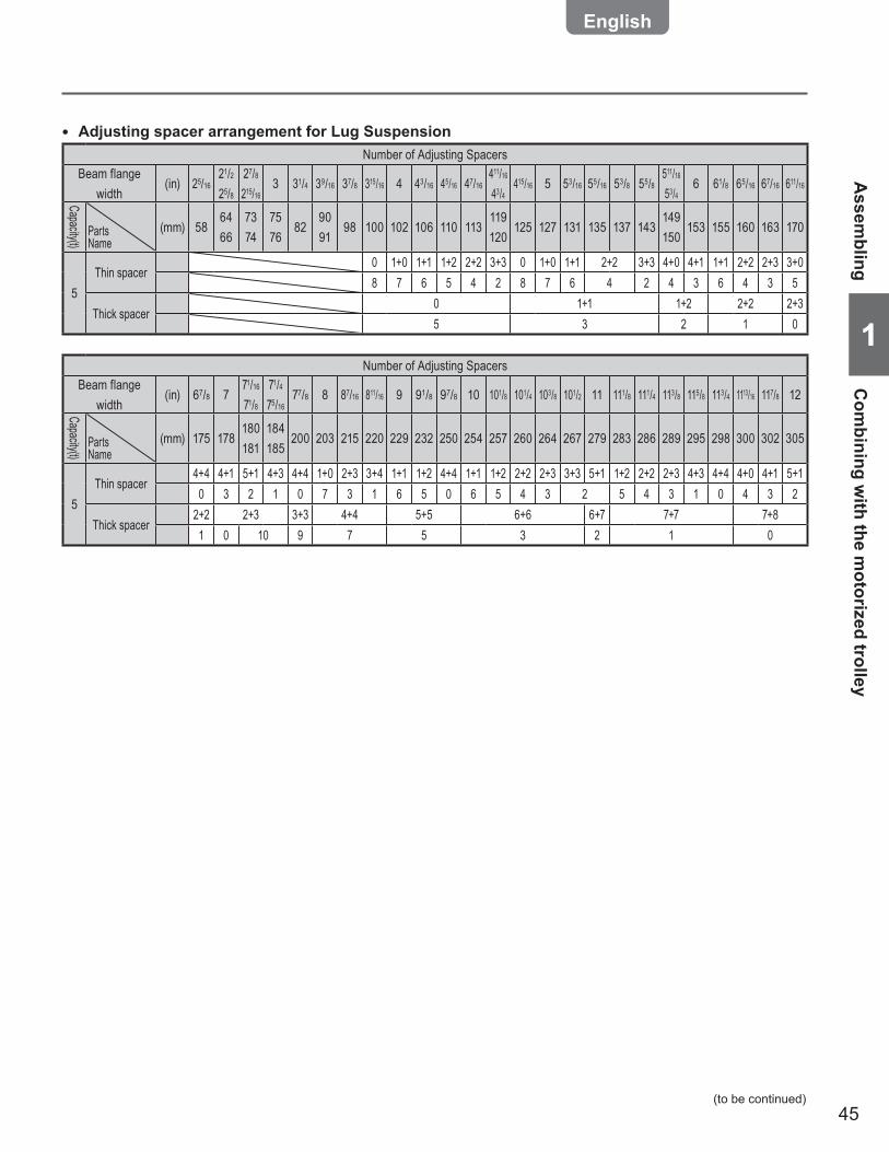
45
11Number of Adjusting Spacers
Beam flange width
(in) 67/8 771/16
71/871/475/16
77/8 8 87/16 811/16 9 91/8 97/8 10 101/8 101/4 103/8 101/2 11 111/8 111/4 113/8 115/8 113/4 1113/16 117/8 12
Capacity(t)
PartsName
(mm) 175 178180181
184185
200 203 215 220 229 232 250 254 257 260 264 267 279 283 286 289 295 298 300 302 305
5Thin spacer
4+4 4+1 5+1 4+3 4+4 1+0 2+3 3+4 1+1 1+2 4+4 1+1 1+2 2+2 2+3 3+3 5+1 1+2 2+2 2+3 4+3 4+4 4+0 4+1 5+10 3 2 1 0 7 3 1 6 5 0 6 5 4 3 2 5 4 3 1 0 4 3 2
Thick spacer2+2 2+3 3+3 4+4 5+5 6+6 6+7 7+7 7+81 0 10 9 7 5 3 2 1 0
Number of Adjusting SpacersBeam flange
width(in) 25/16
21/225/8
27/8215/16
3 31/4 39/16 37/8 315/16 4 43/16 45/16 47/16411/16
43/4415/16 5 53/16 55/16 53/8 55/8
511/16
53/46 61/8 65/16 67/16 611/16
Capacity(t)
PartsName
(mm) 586466
7374
7576
829091
98 100 102 106 110 113119120
125 127 131 135 137 143149150
153 155 160 163 170
5Thin spacer
0 1+0 1+1 1+2 2+2 3+3 0 1+0 1+1 2+2 3+3 4+0 4+1 1+1 2+2 2+3 3+08 7 6 5 4 2 8 7 6 4 2 4 3 6 4 3 5
Thick spacer0 1+1 1+2 2+2 2+35 3 2 1 0
Adjusting spacer arrangement for Lug Suspension ●
Assem
blingC
ombining w
ith the motorized trolley
(to be continued)
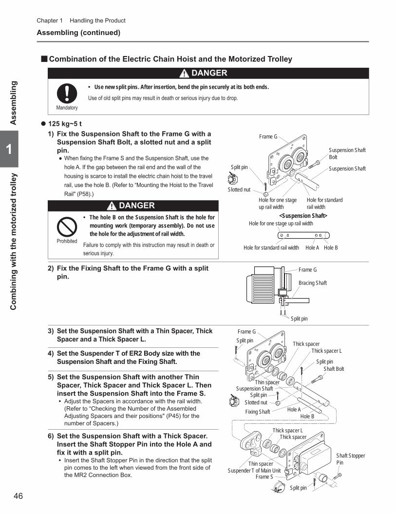
46
1
Chapter 1 Handling the Product
Assembling (continued)
Ass
embl
ing
Com
bini
ng w
ith th
e m
otor
ized
trol
ley
Combination of the Electric Chain Hoist and the Motorized Trolley ■
125 kg~5 t ●
1) Fix the Suspension Shaft to the Frame G with a Suspension Shaft Bolt, a slotted nut and a split pin.
When fixing the Frame S and the Suspension Shaft, use the ●hole A. If the gap between the rail end and the wall of the housing is scarce to install the electric chain hoist to the travel rail, use the hole B. (Refer to “Mounting the Hoist to the Travel Rail" (P58).)
3) Set the Suspension Shaft with a Thin Spacer, Thick Spacer and a Thick Spacer L.
4) Set the Suspender T of ER2 Body size with the Suspension Shaft and the Fixing Shaft.
5) Set the Suspension Shaft with another Thin Spacer, Thick Spacer and Thick Spacer L. Then insert the Suspension Shaft into the Frame S.
Adjust the Spacers in accordance with the rail width. •(Refer to “Checking the Number of the Assembled Adjusting Spacers and their positions" (P45) for the number of Spacers.)
6) Set the Suspension Shaft with a Thick Spacer. Insert the Shaft Stopper Pin into the Hole A and fix it with a split pin.
Insert the Shaft Stopper Pin in the direction that the split •pin comes to the left when viewed from the front side of the MR2 Connection Box.
Use new split pins. After insertion, bend the pin securely at its both ends. •
Use of old split pins may result in death or serious injury due to drop.Mandatory
Frame G
Suspension Shaft Bolt
Suspension ShaftSplit pin
Slotted nut
Hole for standard rail width
Hole for one stage up rail width
<Suspension Shaft>
Hole for standard rail width Hole A Hole B
Hole for one stage up rail width
2) Fix the Fixing Shaft to the Frame G with a split pin.
Split pin
Bracing Shaft
Frame G
Split pinFrame G
Thin spacer
Thin spacer
Thick spacerThick spacer L
Split pinShaft Bolt
Suspension ShaftSplit pin
Thick spacer LThick spacer
Hole AHole B
Fixing Shaft
Suspender T of Main UnitFrame S
Split pin
Shaft Stopper Pin
Slotted nut
The hole B on the Suspension Shaft is the hole for •mounting work (temporary assembly). Do not use the hole for the adjustment of rail width.
Failure to comply with this instruction may result in death or serious injury.
Prohibited
DANGER
DANGER

47
11
Combination with the Manual Ttrolley ■Parts replacement of the Electric Chain Hoist ■Remove the Top Hook and replace it with a Connection Yoke.
Replacing the Top Hook of Body size ER2-B/C/D/ ● E
1) Remove the Shaft Retainer Clip using plier.
2) Remove Socket Bolt from the Shaft Retainer, and remove the Shaft Retainer.
3) Remove two Connection Shafts.
4) Remove the Top Hook and replace it with the Connection Yoke.
5) Insert two Connection Shafts into the hole of the Body size.
6) Mount the Shaft Retainer with Socket Bolt.
Replacing the Top Hook of Body size ER2-F ●
1) Remove four Socket Bolts and remove the Controller Cover.
2) Remove pan head screws of the Connection Shaft and the Fixing Shaft (two screws each), and remove the Shaft Retainer.
3) Pinch the respective upper ends of the Connection Shaft and the Fixing Shaft and pull out them.
4) Remove the Top Hook and replace it with the Suspender T.
5) Insert the Connection Shaft and Fixing Shaft into the mounting hole.
6) Fix the Shaft Retainer of the Connection Shaft and the Fixing Shaft with pan head screws (two screws each).
7) Mount the Controller Cover with four pan head screws.
Connection ShaftShaft Retainer
Shaft Retainer Clip
Connection Shaft
Bracing Shaft
Controller Cover
Socket Bolt
O ring
O ringShaft Retainer
Shaft Retainer
Pan head screw
Pan head screw
Panel
Top Hook
Socket Bolt
Top Hook
Connection Yok
Geard Trolley Plain Trolley
Connection Yoke
For Double Chain Type
Geard Trolley Plain Trolley For Double Chain Type
(to be continued)
Assem
blingC
ombination w
ith the Manual Ttrolley

48
1
Chapter 1 Handling the Product
Assembling (continued)
Checking the Number of the Assembled Adjusting Spacers and Their Positions ■When installing a trolley to the beam, the length of the Suspension Shaft (width between frames) must be adjusted in accordance with the rail width. Wrong number of wrong position of Spacers may result in the drop of the electric chain hoist. Insert the correct number of Spacers with correct ratings and for rail width at the correct position, referring to the following table.
Ass
embl
ing
Com
bina
tion
with
the
Man
ual T
trol
ley
Number of Adjusting SpacersBeam flange
width(in) 2 25/16
21/225/8
27/8215/16
3 31/4 39/16 37/8 315/16 4 43/16 415/16 47/16411/16
43/4415/16 5 53/16 55/16 53/8 55/8
57/8515/16
6 61/8 65/16 67/16
Capacity Parts(mm) 50 58
6466
7374
7576
829091
98 100 102 106 110 113119120
125 127 131 135 137 143149150
153 155 160 163
0.5
Thin spacerInner 2+3 3+4 0+1 1+2 2+2 3+3 0+1 1+2 2+2 2+3 1+1 1+2 2+2 3+3 0+0 0+1 1+1 1+2 2+2 3+3 0+0 0+1 1+1 1+2 2+2Outer 4 2 8 6 5 3 8 6 5 4 7 6 5 3 9 8 7 6 5 3 9 8 7 6 5
Thick spacerInner 0+0 0+0 1+1 1+1 1+1 1+1 2+2 2+2 2+2 2+2 0+0 0+0 0+0 0+0 1+1 1+1 1+1 1+1 1+1 1+1 2+2 2+2 2+2 2+2 2+2Outer 4 4 2 2 2 2 0 0 0 0 7 7 7 7 5 5 5 5 5 5 3 3 3 3 3
Fixing spacer Inner – – – – – – – – – – 1+1 1+1 1+1 1+1 1+1 1+1 1+1 1+1 1+1 1+1 1+1 1+1 1+1 1+1 1+1
1
Thin spacerInner 3+3 0+0 1+1 1+2 2+3 0+0 1+1 1+2 2+2 2+3 3+3 3+4 0+1 1+2 2+2 1+1 1+2 2+2 3+3 0+0 0+1 1+1 1+2 2+2Outer 2 8 6 5 3 8 6 5 4 3 2 1 7 5 4 7 6 5 3 9 8 7 6 5
Thick spacerInner 0+0 1+1 1+1 1+1 1+1 2+2 2+2 2+2 2+2 2+2 2+2 2+2 3+3 3+3 3+3 0+0 0+0 0+0 0+0 1+1 1+1 1+1 1+1 1+1Outer 6 4 4 4 4 2 2 2 2 2 2 2 0 0 0 5 5 5 5 3 3 3 3 3
Fixing spacer Inner – – – – – – – – – – – – – – – 1+1 1+1 1+1 1+1 1+1 1+1 1+1 1+1 1+1
2
Thin spacerInner 2+2 3+4 0+1 1+1 1+2 2+2 2+3 3+3 0+0 1+1 1+2 2+2 2+3 3+3 0+0 1+1 1+2 1+1 1+2 2+2Outer 3 0 6 5 4 3 2 1 7 5 4 3 2 1 7 5 4 7 6 5
Thick spacerInner 0+0 0+0 1+1 1+1 1+1 1+1 1+1 1+1 2+2 2+2 2+2 2+2 2+2 2+2 3+3 3+3 3+3 0+0 0+0 0+0Outer 6 6 4 4 4 4 4 4 2 2 2 2 2 2 0 0 0 11 11 11
Fixing spacer Inner – – – – – – – – – – – – – – – – – 1+1 1+1 1+1
3
Thin spacerInner 1+2 3+3 0+0 0+1 1+1 1+2 2+2 2+3 3+4 0+1 1+1 1+2 2+2 2+3 3+4 1+4 1+5 1+1 1+2 2+2Outer 7 4 10 9 8 7 6 5 3 9 8 7 6 5 3 5 4 7 6 5
Thick spacerInner 2+2 2+2 3+3 3+3 3+3 3+3 3+3 3+3 3+3 4+4 4+4 4+4 4+4 4+4 4+4 5+4 5+4 0+0 0+0 0+0Outer 5 5 3 3 3 3 3 3 3 1 1 1 1 1 1 0 0 11 11 11
Fixing spacer Inner – – – – – – – – – – – – – – – – – 1+1 1+1 1+1
5
Thin spacerInner 0+0 0+1 1+1 1+2 2+2 3+3 0+0 0+1 1+1 1+2 2+2 3+3 0+0 0+1 1+2 1+2 2+2Outer 8 7 6 5 4 2 8 7 6 5 4 2 8 7 6 5 4
Thick spacerInner 0+0 0+0 0+0 0+0 0+0 0+0 1+1 1+1 1+1 1+1 1+1 1+1 2+2 2+2 2+2 2+2 2+2Outer 5 5 5 5 5 5 3 3 3 3 3 3 1 1 1 1 1
Fixing spacer Inner – – – – – – – – – – – – – – – – –
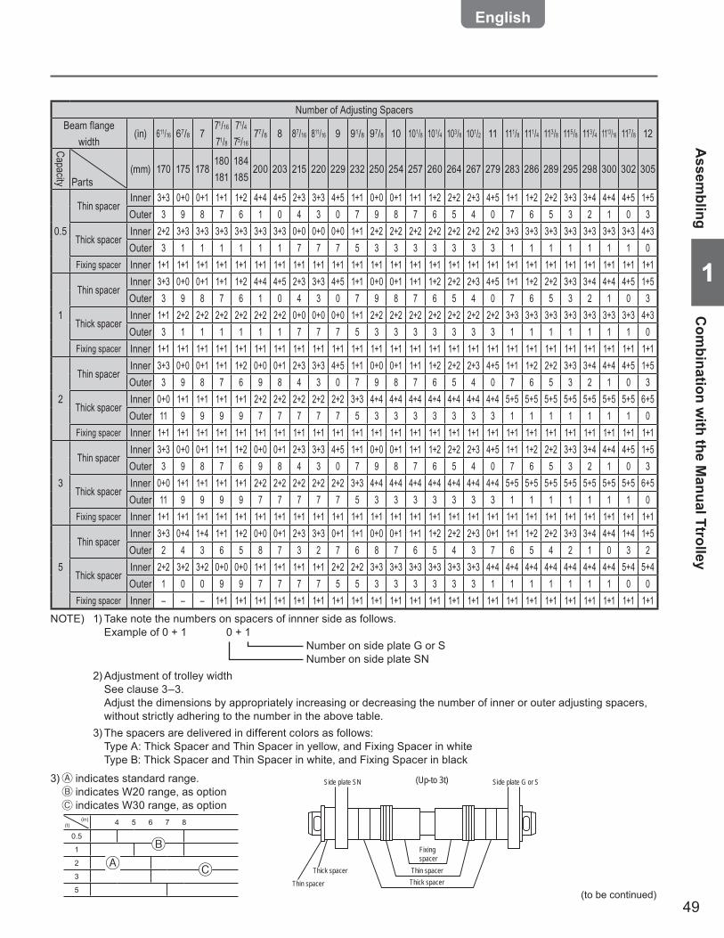
49
11
(to be continued)
Assem
blingC
ombination w
ith the Manual Ttrolley
Number of Adjusting SpacersBeam flange
width(in) 611/16 67/8 7
71/16
71/871/475/16
77/8 8 87/16 811/16 9 91/8 97/8 10 101/8 101/4 103/8 101/2 11 111/8 111/4 113/8 115/8 113/4 1113/16 117/8 12
Capacity Parts(mm) 170 175 178
180181
184185
200 203 215 220 229 232 250 254 257 260 264 267 279 283 286 289 295 298 300 302 305
0.5
Thin spacerInner 3+3 0+0 0+1 1+1 1+2 4+4 4+5 2+3 3+3 4+5 1+1 0+0 0+1 1+1 1+2 2+2 2+3 4+5 1+1 1+2 2+2 3+3 3+4 4+4 4+5 1+5Outer 3 9 8 7 6 1 0 4 3 0 7 9 8 7 6 5 4 0 7 6 5 3 2 1 0 3
Thick spacerInner 2+2 3+3 3+3 3+3 3+3 3+3 3+3 0+0 0+0 0+0 1+1 2+2 2+2 2+2 2+2 2+2 2+2 2+2 3+3 3+3 3+3 3+3 3+3 3+3 3+3 4+3Outer 3 1 1 1 1 1 1 7 7 7 5 3 3 3 3 3 3 3 1 1 1 1 1 1 1 0
Fixing spacer Inner 1+1 1+1 1+1 1+1 1+1 1+1 1+1 1+1 1+1 1+1 1+1 1+1 1+1 1+1 1+1 1+1 1+1 1+1 1+1 1+1 1+1 1+1 1+1 1+1 1+1 1+1
1
Thin spacerInner 3+3 0+0 0+1 1+1 1+2 4+4 4+5 2+3 3+3 4+5 1+1 0+0 0+1 1+1 1+2 2+2 2+3 4+5 1+1 1+2 2+2 3+3 3+4 4+4 4+5 1+5Outer 3 9 8 7 6 1 0 4 3 0 7 9 8 7 6 5 4 0 7 6 5 3 2 1 0 3
Thick spacerInner 1+1 2+2 2+2 2+2 2+2 2+2 2+2 0+0 0+0 0+0 1+1 2+2 2+2 2+2 2+2 2+2 2+2 2+2 3+3 3+3 3+3 3+3 3+3 3+3 3+3 4+3Outer 3 1 1 1 1 1 1 7 7 7 5 3 3 3 3 3 3 3 1 1 1 1 1 1 1 0
Fixing spacer Inner 1+1 1+1 1+1 1+1 1+1 1+1 1+1 1+1 1+1 1+1 1+1 1+1 1+1 1+1 1+1 1+1 1+1 1+1 1+1 1+1 1+1 1+1 1+1 1+1 1+1 1+1
2
Thin spacerInner 3+3 0+0 0+1 1+1 1+2 0+0 0+1 2+3 3+3 4+5 1+1 0+0 0+1 1+1 1+2 2+2 2+3 4+5 1+1 1+2 2+2 3+3 3+4 4+4 4+5 1+5Outer 3 9 8 7 6 9 8 4 3 0 7 9 8 7 6 5 4 0 7 6 5 3 2 1 0 3
Thick spacerInner 0+0 1+1 1+1 1+1 1+1 2+2 2+2 2+2 2+2 2+2 3+3 4+4 4+4 4+4 4+4 4+4 4+4 4+4 5+5 5+5 5+5 5+5 5+5 5+5 5+5 6+5Outer 11 9 9 9 9 7 7 7 7 7 5 3 3 3 3 3 3 3 1 1 1 1 1 1 1 0
Fixing spacer Inner 1+1 1+1 1+1 1+1 1+1 1+1 1+1 1+1 1+1 1+1 1+1 1+1 1+1 1+1 1+1 1+1 1+1 1+1 1+1 1+1 1+1 1+1 1+1 1+1 1+1 1+1
3
Thin spacerInner 3+3 0+0 0+1 1+1 1+2 0+0 0+1 2+3 3+3 4+5 1+1 0+0 0+1 1+1 1+2 2+2 2+3 4+5 1+1 1+2 2+2 3+3 3+4 4+4 4+5 1+5Outer 3 9 8 7 6 9 8 4 3 0 7 9 8 7 6 5 4 0 7 6 5 3 2 1 0 3
Thick spacerInner 0+0 1+1 1+1 1+1 1+1 2+2 2+2 2+2 2+2 2+2 3+3 4+4 4+4 4+4 4+4 4+4 4+4 4+4 5+5 5+5 5+5 5+5 5+5 5+5 5+5 6+5Outer 11 9 9 9 9 7 7 7 7 7 5 3 3 3 3 3 3 3 1 1 1 1 1 1 1 0
Fixing spacer Inner 1+1 1+1 1+1 1+1 1+1 1+1 1+1 1+1 1+1 1+1 1+1 1+1 1+1 1+1 1+1 1+1 1+1 1+1 1+1 1+1 1+1 1+1 1+1 1+1 1+1 1+1
5
Thin spacerInner 3+3 0+4 1+4 1+1 1+2 0+0 0+1 2+3 3+3 0+1 1+1 0+0 0+1 1+1 1+2 2+2 2+3 0+1 1+1 1+2 2+2 3+3 3+4 4+4 1+4 1+5Outer 2 4 3 6 5 8 7 3 2 7 6 8 7 6 5 4 3 7 6 5 4 2 1 0 3 2
Thick spacerInner 2+2 3+2 3+2 0+0 0+0 1+1 1+1 1+1 1+1 2+2 2+2 3+3 3+3 3+3 3+3 3+3 3+3 4+4 4+4 4+4 4+4 4+4 4+4 4+4 5+4 5+4Outer 1 0 0 9 9 7 7 7 7 5 5 3 3 3 3 3 3 1 1 1 1 1 1 1 0 0
Fixing spacer Inner – – – 1+1 1+1 1+1 1+1 1+1 1+1 1+1 1+1 1+1 1+1 1+1 1+1 1+1 1+1 1+1 1+1 1+1 1+1 1+1 1+1 1+1 1+1 1+1NOTE) 1) Take note the numbers on spacers of innner side as follows. Example of 0 + 1 0 + 1 Number on side plate G or S Number on side plate SN 2) Adjustment of trolley width See clause 3–3. Adjust the dimensions by appropriately increasing or decreasing the number of inner or outer adjusting spacers,
without strictly adhering to the number in the above table. 3) The spacers are delivered in different colors as follows: Type A: Thick Spacer and Thin Spacer in yellow, and Fixing Spacer in white Type B: Thick Spacer and Thin Spacer in white, and Fixing Spacer in black
3) indicates standard range. indicates W20 range, as option indicates W30 range, as option
(in)(t) 4 5 6 7 8
0.5
1
2
3
5Thin spacer
Thin spacerThick spacerThick spacer
Side plate SN Side plate G or S(Up-to 3t)
Fixing spacer

50
1
Chapter 1 Handling the Product
Assembling (continued)
Ass
embl
ing
Com
bina
tion
with
the
Man
ual T
trol
ley
Combination of the Electric Chain Hoist and the Manual Trolley ■
125 kg~3 t ●
1) After setting the Suspension Shaft with Spacers, insert it into Frame G or Frame S and fix it with a Shaft Stopper Pin and a Split Pin.
Insert the Shaft Stopper Pin in the direction that the •split pin comes to the right when viewed from the side of the Frame G or Frame S.Open the both ends of the Split Pin by 70˚ or more. •
2) Set the Suspension Shaft with a Thin Spacer, Thick Spacer and Fixing Spacer.
3) Set the Suspender with the Suspension Shaft.
4) Set the Suspension Shaft with another Thin Spacer, Thick Spacer and Fixing Spacer. Then insert the Suspension Shaft into the Frame SN.
Adjust the Spacers in accordance with the rail width. •(Refer to “Checking the Number of the Assembled Adjusting Spacers and Their Positions" (P50) for the number of Spacers.)
5) Set the Suspension Shaft with a Thick Spacer. Fix it with a Shaft Stopper Pin and a split pin.
Insert the Shaft Stopper Pin in the direction that the •split pin comes to the right when viewed from the front side of the Frame SN.Open the both ends of the Split Pin by 70˚ or more. •
Use new split pins. After insertion, bend the pin securely at its both ends. •
Use of old split pins may result in death or serious injury due to drop.Mandatory
70° or more
Split pin
Split pin
Split pin
Shaft Stopper Pin
Frame SN
Shaft Stopper Pin
Suspension Shaft
Hand Chain
Thin spacer (t=3.2)
Thin spacer (t=3.2)
Frame G
Frame S
Shaft Stopper Pin
Fixing spacer
Fixing spacer
Thick spacerThin spacer
Thick spacer
Yoke Bolt
Thick spacer
Thin spacer
Orientation of Shaft Stopper PinBending the split pin
Split pin
Slotted nut
Suspender of the Main Unit
Suspender
6) Mount the Suspender to the Connection Yoke with a Yoke Bolt, a slotted nut and a split pin.
The orientation of the Geared Trolley with the •rating of 2.5 t or less combined with the electric chain hoist differs from that of the Plain Trolley combined with the electric chain hoist by 90 degrees. Combine the trolley and the electric chain hoist correctly referring to the figure in “Models and Names of Each Part" (P12).
Failure to comply with this instruction causes bodily injury or loss of property.
CAUTION
Mandatory
DANGER
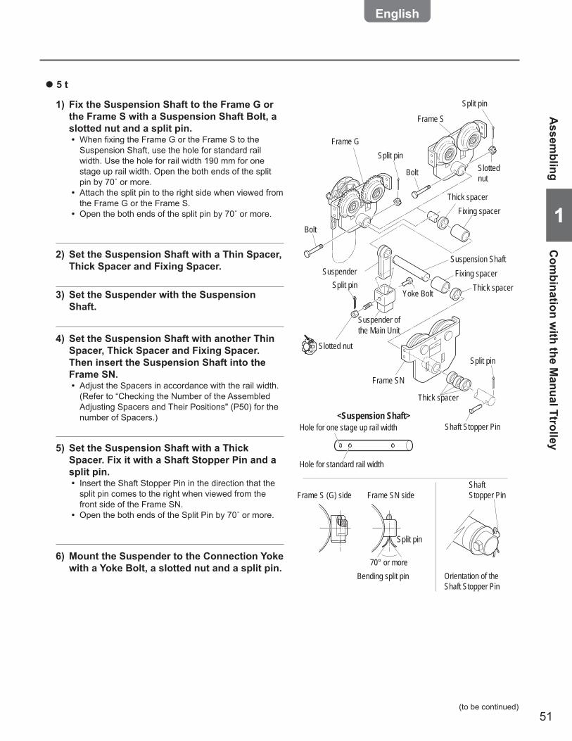
51
11
5 t ●
1) Fix the Suspension Shaft to the Frame G or the Frame S with a Suspension Shaft Bolt, a slotted nut and a split pin.
When fixing the Frame G or the Frame S to the •Suspension Shaft, use the hole for standard rail width. Use the hole for rail width 190 mm for one stage up rail width. Open the both ends of the split pin by 70˚ or more.Attach the split pin to the right side when viewed from •the Frame G or the Frame S.Open the both ends of the split pin by 70˚ or more. •
2) Set the Suspension Shaft with a Thin Spacer, Thick Spacer and Fixing Spacer.
3) Set the Suspender with the Suspension Shaft.
4) Set the Suspension Shaft with another Thin Spacer, Thick Spacer and Fixing Spacer. Then insert the Suspension Shaft into the Frame SN.
Adjust the Spacers in accordance with the rail width. •(Refer to “Checking the Number of the Assembled Adjusting Spacers and Their Positions" (P50) for the number of Spacers.)
5) Set the Suspension Shaft with a Thick Spacer. Fix it with a Shaft Stopper Pin and a split pin.
Insert the Shaft Stopper Pin in the direction that the •split pin comes to the right when viewed from the front side of the Frame SN.Open the both ends of the Split Pin by 70˚ or more. •
Suspender
Frame SN
Suspension Shaft
Frame G
Frame S
Frame S (G) side Frame SN sideShaft Stopper Pin
Fixing spacer
Fixing spacerThick spacer
Slotted nut
Yoke BoltSplit pin
Split pin
Shaft Stopper Pin
Thick spacer
Thick spacer
Orientation of the Shaft Stopper Pin
70° or more
Split pin
Split pin
Split pinSlotted nut
Bolt
Bolt
Bending split pin
<Suspension Shaft>
Hole for standard rail width
Hole for one stage up rail width
Suspender of the Main Unit
6) Mount the Suspender to the Connection Yoke with a Yoke Bolt, a slotted nut and a split pin.
(to be continued)
Assem
blingC
ombination w
ith the Manual Ttrolley

52
1
Chapter 1 Handling the Product
Do not use the cable other than the cable attached to the Body size or optional Power Cable. •
Failure to comply with this instruction causes bodily injury or loss of property.Prohibited
Satisfy the maximum permissible length and core cross section of the Power Cable. •
Failure to comply with this instruction causes bodily injury or loss of property.Mandatory
CAUTION
Assembling (continued)
Ass
embl
ing
Che
ckin
g Po
wer
and
Pow
er C
able
Checking Power and Power Cable ■
Check that the rating of the breaker satisfies the specification required by the electric chain hoist. •Check that the source voltage satisfies the rated voltage of the electric chain hoist. •Use a breaker with a capacity in conformance with the product specifications. •
Failure to comply with this instruction may result in death or serious injury.Mandatory
DANGER
Checking the Power Cable ■
Hook suspendeed Type:ER2 ●Manual trolly type:ER2SP/ER2SG
Motorized trolly type:ER2M ●
CodeCapacity of fuse and circuit breaker (A)
Wire size(mm2)
220/440V ClassSingle speed Dual speed
ER2-001H/IH
AWG16
5/5 5/5ER2-003S/ISER2-005L/ILER2-003H/IH
10/5 10/5ER2-005S/ISER2-010L/ILER2-010S/IS
15/10 15/10ER2-015S/ISER2-020C/ICER2-020L/ILER2-020S/IS
AWG14 30/10 30/15ER2-025S/ISER2-030S/ISER2-050S/IS
Code
Capacity of fuse and circuit breaker (A)
Wire size(mm2)
220/440V ClassER SingleMR Single
ER DualMR Dual
ER2-001H/IH
AWG14
10/5 10/5ER2-003S/ISER2-005L/ILER2-003H/IH
15/10
15/10ER2-005S/ISER2-010L/ILER2-010S/IS
20/10ER2-015S/ISER2-020C/ICER2-020L/ILER2-020S/IS
AWG12 30/15 30/15ER2-025S/ISER2-030S/ISER2-050S/IS
Code Wire size(mm2)
Capacity of fuse and circuit breaker (A)500V Class
Single speed Dual speedER2-001H/HD
1.25 5 5
ER2-003S/SDER2-005L/LDER2-003H/HDER2-005S/SDER2-010L/LDER2-010S/SDER2-015S/SDER2-020C/CDER2-020L/LDER2-020S/SD
2 10 10ER2-025S/SDER2-030S/SDER2-050S/SD
Code Wire size(mm2)
Capacity of fuse and circuit breaker (A)500V Class
ER SingleMR Single
ER DualMR Dual
ER2-001H/HD
2 5 5
ER2-003S/SDER2-005L/LDER2-003H/HDER2-005S/SDER2-010L/LDER2-010S/SDER2-015S/SDER2-020C/CDER2-020L/LDER2-020S/SD
3.5 10 10ER2-025S/SDER2-030S/SDER2-050S/SD 20 20
Checking the Power ■
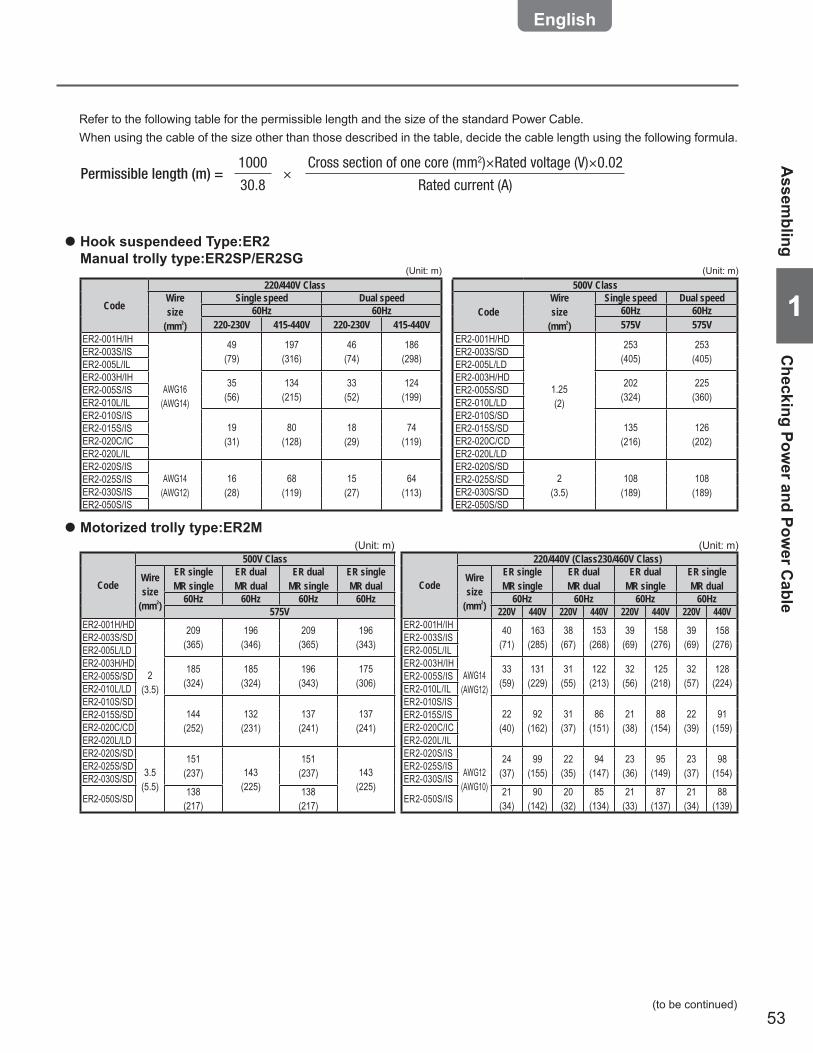
53
11
Hook suspendeed Type:ER2 ●Manual trolly type:ER2SP/ER2SG
Motorized trolly type:ER2M ●
Permissible length (m) = ×1000
30.8
Cross section of one core (mm2)×Rated voltage (V)×0.02
Rated current (A)
Refer to the following table for the permissible length and the size of the standard Power Cable.When using the cable of the size other than those described in the table, decide the cable length using the following formula.
(to be continued)
Assem
blingC
hecking Power and Pow
er Cable
Code
220/440V ClassWiresize
(mm2)
Single speed Dual speed60Hz 60Hz
220-230V 415-440V 220-230V 415-440VER2-001H/IH
AWG16(AWG14)
49(79)
197(316)
46(74)
186(298)ER2-003S/IS
ER2-005L/ILER2-003H/IH 35
(56)134
(215)33
(52)124
(199)ER2-005S/ISER2-010L/ILER2-010S/IS
19(31)
80(128)
18(29)
74(119)
ER2-015S/ISER2-020C/ICER2-020L/ILER2-020S/IS
AWG14(AWG12)
16(28)
68(119)
15(27)
64(113)
ER2-025S/ISER2-030S/ISER2-050S/IS
500V Class
CodeWiresize
(mm2)
Single speed Dual speed60Hz 60Hz575V 575V
ER2-001H/HD
1.25(2)
253(405)
253(405)ER2-003S/SD
ER2-005L/LDER2-003H/HD 202
(324)225
(360)ER2-005S/SDER2-010L/LDER2-010S/SD
135(216)
126(202)
ER2-015S/SDER2-020C/CDER2-020L/LDER2-020S/SD
2(3.5)
108(189)
108(189)
ER2-025S/SDER2-030S/SDER2-050S/SD
Code
500V Class
Wiresize
(mm2)
ER singleMR single
ER dualMR dual
ER dualMR single
ER singleMR dual
60Hz 60Hz 60Hz 60Hz575V
ER2-001H/HD
2(3.5)
209(365)
196(346)
209(365)
196(343)ER2-003S/SD
ER2-005L/LDER2-003H/HD 185
(324)185
(324)196
(343)175
(306)ER2-005S/SDER2-010L/LDER2-010S/SD
144(252)
132(231)
137(241)
137(241)
ER2-015S/SDER2-020C/CDER2-020L/LDER2-020S/SD
3.5(5.5)
151(237) 143
(225)
151(237) 143
(225)
ER2-025S/SDER2-030S/SD
ER2-050S/SD 138(217)
138(217)
Code
220/440V (Class230/460V Class)
Wiresize
(mm2)
ER singleMR single
ER dualMR dual
ER dualMR single
ER singleMR dual
60Hz 60Hz 60Hz 60Hz220V 440V 220V 440V 220V 440V 220V 440V
ER2-001H/IH
AWG14(AWG12)
40(71)
163(285)
38(67)
153(268)
39(69)
158(276)
39(69)
158(276)ER2-003S/IS
ER2-005L/ILER2-003H/IH 33
(59)131
(229)31
(55)122
(213)32
(56)125
(218)32
(57)128
(224)ER2-005S/ISER2-010L/ILER2-010S/IS
22(40)
92(162)
31(37)
86(151)
21(38)
88(154)
22(39)
91(159)
ER2-015S/ISER2-020C/ICER2-020L/ILER2-020S/IS
AWG12(AWG10)
24(37)
99(155)
22(35)
94(147)
23(36)
95(149)
23(37)
98(154)ER2-025S/IS
ER2-030S/IS
ER2-050S/IS 21(34)
90(142)
20(32)
85(134)
21(33)
87(137)
21(34)
88(139)
(Unit: m)
(Unit: m)(Unit: m)
(Unit: m)

54
1
Chapter 1 Handling the Product
Assembling (continued)
Ass
embl
ing
Con
nect
ing
Cab
les
2) Fix the Power Cable using cable support with a slack.
1) Insert the 4-pin plug of the Power Cable to the socket (4P) and tighten the Lock Ring securely.
Connecting the Power Cable ●
Connecting the Push Button Switch Cord ●
1) Insert the 8-pin connector plug of the Push Button Cord to the connector socket (8P) and tighten the Lock Ring securely.
2) Pass the Cable Support L into the ring at the end of the Protection Wire. Put the Protection Wire or Chain in the notch of the Cable Support L.
Then fix the Cable Support L to the body size (at the bottom face of the Gear Case).
NOTEWhen clamping a connector, do not use tools. Be sure to clamp it by hand. •Excessive tightening of a connector may result in the damage or breakage f plastic thread part.To prevent wire breakage and unintentional removal of a connector, tie the protection wire attached to the Push Button Switch •Cord to the body size of the electric chain hoist or the trolley.Be sure to tie the cord with the body size or the trolley to prevent the wire breakage and removal of connector when the cord is pulled strongly.Be sure to turn off the power when carrying out the repair work of wire breakage or removal of the connector. •
1
Lock Ring2
Cable holder Cable holder arm
Connector Socket holder
Connector Plug (8P)
Connector Socket (8P)
Cable Support L
Pan head screw
Protection wire orChain
Lock Ring
Connector Plug (4P)
Pan head screw
Connector Socket (4P)
Cable Support L
Connecting Cables ■
Hook suspended model (hoist only) ■125 kg~5 t ■

55
11
Lock Ring
Connector socket (4P)
Connector plug (4P)
Connector plug (8P)
Connector socket (8P)
Electric chain hoist
Chain retainerPan head screw
Protection wireor Chain
Connector plug (8P)Connector socket (8P)
Connection Box
Pan head screw
Relay cable for power
Relay cable for operation
Cable packing
Holder AHolder B
Power Cable(to Power or Crain Control Box)
Chain retainer
Split pinSlotted nutCable holder
Power Cable
Chain hanging pin BCable holder arm
2) Insert the connector plug (8P) of relay cable for operation in the connector socket (8P) of ER2. Tighten the Lock Ring securely.
1) Insert the connector plug (4P) of relay cable for power supply in the connector socket (4P) of ER2. Tighten the Lock Ring securely.
Connecting the relay cable ●
2) Pass the Power Cable through the Holder A supported by the cable holder and the cable packing.
1) Remove the Holder A mounted to the Connection Box.
Connecting the Power Cable ●
2) Pass the Chain retainer into the hoop at the end of the Protection Wire or Chain and fix it to the bar holder with a pan head screw.
1) Insert the connector plug (8P) of Push Button Switch Cord in the connector socket (8P). Tighten the Lock Ring securely.
Direct-mount ●1) Mount the Holder B, which the Push Button Switch
Cord is passed, to the plate D using the holder nut.2) Connect the Push Button Switch Cord to the
terminal panel of the Connection Box.
Connecting the Push Button Switch Cord ●
Holder nut Plate DHolder B
Holder A
<Trolley Power Cable Connection>
<Direct-mount Push Button Switch Cord Connection>
3) Insert the Power Cable to the Holder B of the Connection Box and tighten the Holder A securely.
Trolley Type ●1) Mount the cable holder, which the Power Cable
is passed, to the cable holder arm using a chain hanging pin B, a slotted nut and a split pin.
4) Connect the Power Cable to the terminal panel of the Connection Box.
Connect wires correctly according to the wiring •diagram affixed on the Connection Box.
Motorized Trolley Type ■125 kg~5 t ■ A
ssembling
Connecting C
ables
(to be continued)
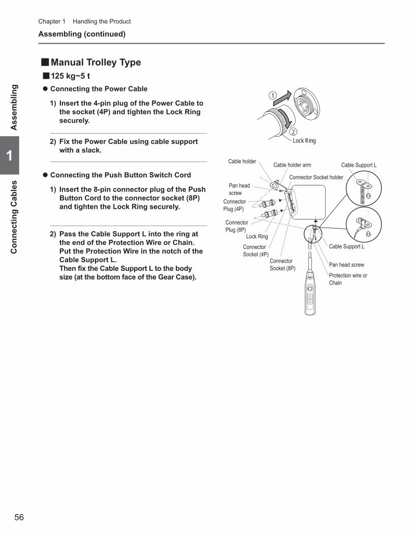
56
1
Chapter 1 Handling the ProductA
ssem
blin
gC
onne
ctin
g C
able
s
Manual Trolley Type ■125 kg~5 t ■
2) Fix the Power Cable using cable support with a slack.
1) Insert the 4-pin plug of the Power Cable to the socket (4P) and tighten the Lock Ring securely.
Connecting the Power Cable ●
Connecting the Push Button Switch Cord ●
1) Insert the 8-pin connector plug of the Push Button Cord to the connector socket (8P) and tighten the Lock Ring securely.
2) Pass the Cable Support L into the ring at the end of the Protection Wire or Chain. Put the Protection Wire in the notch of the Cable Support L.
Then fix the Cable Support L to the body size (at the bottom face of the Gear Case).
1
Lock Ring2
Cable holder Cable holder arm
Connector Socket holder
Connector Plug (8P)
Connector Socket (8P)
Cable Support L
Pan head screw
Protection wire orChain
Lock Ring
Connector Plug (4P)
Pan head screw
Connector Socket (4P)
Cable Support L
Assembling (continued)

57
11
Installation
Installing the Hook Suspended Type (hoist only) ■Checking Installation Method and Place ■
CAUTIONConnect the Power Cable to the power of rated voltage. •
Failure to comply with this instruction causes bodily injury or loss of property.Mandatory
Installation (removal) of the electric chain hoist must be carried out by special installer or by personnel with expertise. •Consult with the sales shop or KITO for installation, or consign the installation work to special installer or personnel with expertise.Do not install the electric chain hoist at a place exposed to rain or water always or the place different from the •Operational Environment (P18).Do not install the electric chain hoist in the motion space of other trolley or any other moving equipment (facility). •Do not use the electric chain hoist contacting with other object, or being fixed. •
Failure to comply with these instructions may result in death or serious injury.
When installing or removing the electric chain hoist, follow the instructions in Owner's Manual. •Carry out the work for grounding (earthing) and installation of earth leakage breaker. •When the installation is completed, carry out “Check after Installation". (See P61) •Connect the power after all installation works have been completed and just before the •oparation check.Mount the stopper at the both ends of the travel rail for trolley. <Fig. A> •Make sure that the strength of the structure is sufficient to install the electric chain hoist. •Carry out the installation work after securing the stable hoothold. •When not using the KITO Standard Trolley and use the Electric Chain Hoist •incorporated as part of your travel device, make sure to contact KITO for precautions.
Failure to comply with these instructions may result in death or serious injury.
Mandatory
Prohibited
Stopper
Travel rail
Trolley
A
When using an electric chain hoist suspended (as a single unit) without combination with a trolley, make •sure that the Hook Latch of the Top Hook closes securely.Make sure that the Top Hook and body can swing freely. Do not restrain the Top Hook and body during use. •Do not install and use the electric chain hoist upside down. •
Failure to comply with these instructions may result in death or serious injury.
Mandatory
Connecting Power and Power Cable ■When connecting the Power Cable to the power, connect the cable in accordance with the following instructions.
Connect the electric chain hoist to the power through a breaker. ●Connect the electric chain hoist in the correct phase. ●(When 'Check after Installation (P61)' is completed, carry out the operation check for the correct phase.)Earth wire is a green colored covered cable with yellow line. Carry out Class D ●earthing work.Use correct breaker and Power Cable referring to Checking the Power and the Power ●Cable (P53) for the breaker capacity, Power Cable length and its size.
L1R-
phase
Red
White
Black
Red
White
Black
Green/Yellow
L2S-
phase
L3T-
phaseBreaker
InstallationC
onnecting Power and Pow
er Cable / Installing the H
ook suspended Type (hoist only)
(to be continued)
DANGER
DANGER
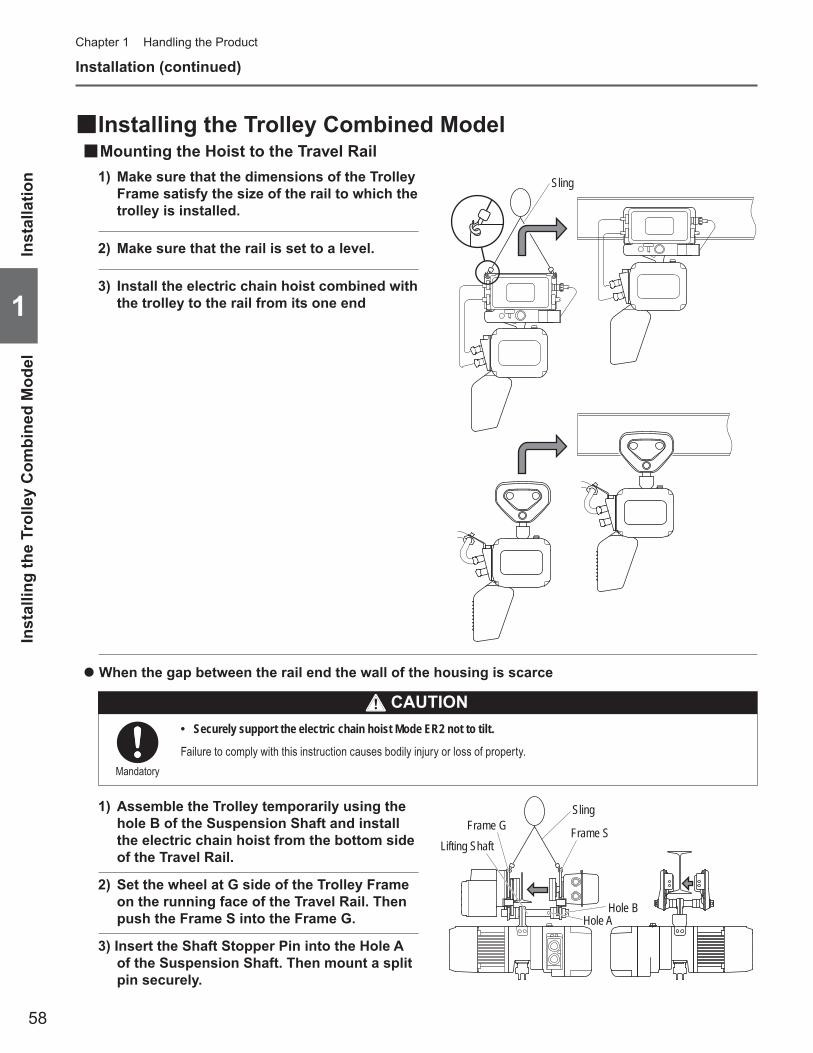
58
1
Chapter 1 Handling the Product
Installation (continued)
Inst
alla
tion
Inst
allin
g th
e Tr
olle
y C
ombi
ned
Mod
el
Installing the Trolley Combined Model ■Mounting the Hoist to the Travel Rail ■
Sling
Hole B
Frame G Frame S
Sling
Hole A
Lifting Shaft
3) Install the electric chain hoist combined with the trolley to the rail from its one end
2) Set the wheel at G side of the Trolley Frame on the running face of the Travel Rail. Then push the Frame S into the Frame G.
1) Assemble the Trolley temporarily using the hole B of the Suspension Shaft and install the electric chain hoist from the bottom side of the Travel Rail.
When the gap between the rail end the wall of the housing is scarce ●
3) Insert the Shaft Stopper Pin into the Hole A of the Suspension Shaft. Then mount a split pin securely.
Securely support the electric chain hoist Mode ER2 not to tilt. •
Failure to comply with this instruction causes bodily injury or loss of property.Mandatory
CAUTION
1) Make sure that the dimensions of the Trolley Frame satisfy the size of the rail to which the trolley is installed.
2) Make sure that the rail is set to a level.
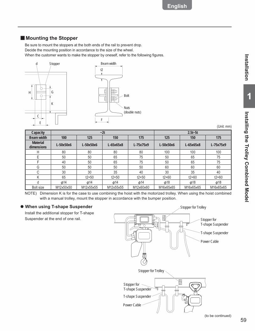
59
11
Capacity ~2t 2.5t~5tBeam width 100 125 150 175 125 150 175
Material dimensions L-50x50x6 L-50x50x6 L-65x65x8 L-75x75x9 L-50x50x6 L-65x65x8 L-75x75x9
H 80 80 80 80 100 100 100E 50 50 65 75 50 65 75F 40 50 65 75 50 65 75G 50 50 50 50 60 60 60C 30 30 35 40 30 35 40K 65 t2+50 t2+50 t2+50 t2+60 t2+60 t2+60d 14 14 14 14 18 18 18
Bolt size M12x50x50 M12x55x55 M12x55x55 M12x60x60 M16x65x65 M16x65x65 M16x65x65NOTE) Dimension K is for the case to use combining the hoist with the motorized trolley. When using the hoist combined
with a manual trolley, mount the stopper in accordance with the bumper position.
F
H
Beam widtht2
BoltG
K
C
E
Stopper
Nuts (double nuts)
d
When using T-shape Suspender ●
Install the additional stopper for T-shape Suspender at the end of one rail.
Power Cable
T-shape Suspender
Stopper for T-shape Suspender
Stopper for Trolley
(Unit: mm)
Power Cable
T-shape Suspender
Stopper for T-shape Suspender
Stopper for Trolley
(to be continued)
InstallationInstalling the Trolley C
ombined M
odel
Mounting the Stopper ■Be sure to mount the stoppers at the both ends of the rail to prevent drop.Decide the mounting position in accordance to the size of the wheel.When the customer wants to make the stopper by oneself, refer to the following figures.

60
1
Chapter 1 Handling the Product
Messenger WireConnection Box
Cable hanger
Power Cable
Wire Guide
Pan head screw
Messenger Wire
Wire support bar
Rail
Wire support bar
Beam Connection Box
Cable support arm
MotorA
A
Cable Hanger
Wire bolt
Power Cable Layout for Motorized/Manual trolley type ■In the standard specification the Suspender is provided. T-shape Suspender and angle type Suspender are also •available as optional parts. T-shape Suspender can be applicable to curved rail, however, the application method differs depending on the condition such as radius of curvature. In such case, contact KITO.
2) Tie the Messenger Wire passed through the Cable Hanger to the Wire Support Bar with two Wire Bolts.
The recommended mounting interval of the Cable •Hangers is 1.5 m to 2 m.Use steel wire of 3 to 6 mm in diameter for the •Messenger Wire.
1) Mount the wire support bar at the both ends of the rail.
3) Loosen two pan head screws and remove the end clip of the wire guide.
4) Pass the Messenger Wire through the groove of the messenger guide. Mount the end clip with two pan head screws.
The dimension A between the side face of the rail •and the groove of the wire guide must be same as that of mounting hole of the Wire support bar for the Messenger Wire and the side face of the rail.
5) Fix the Power Cable to the Cable Hanger.
6) Mount the Cable Support to the Cable Support Arm.
7) Insert the Power Cable into the Connection Box of MR2 and connect it to the terminal panel.
Connect wires correctly according to the wiring •diagram affixed on the Connection Box.
Inst
alla
tion
Inst
allin
g th
e Tr
olle
y C
ombi
ned
Mod
el
Installation (continued)

61
11
Check after InstallationWrong assembling or installation causes death or serious injury. To prevent such danger check the following.
Check items ■Make sure that the following are satisfied:
No bolt, nut nor split pin is lost. Tightening and assembling are completed. •Protection Wire for Push Button Switch Cord is securely tied to accept and endure the force instead of Push Button •Switch Cord when the Push Button Switch Set is drawn.The Power Cable is fixed to the Cable Support. •Source voltage is the rated voltage •Grounding Wire (earth wire) is connected securely. •
When using with a Trolley ●Check the following:
The electric chain hoist and the trolley are combined correctly. •The stoppers for trolley are securely mounted to Travel Rail where the Trolley travels. •The surface of Travel Rail is not attached with paint or oil. (The surface of the Travel Rail must be basis metal. Do not •paint.) There is no obstacle for the trolley to travel. The Travel Rail is set to a level.)
Operational Check ■Carry out the operational check in accordance with Daily inspection (P20).
Check after Installation
62
Chapter 1 Handling the Product
63
Chapter 2Inspection
This chapter describes frequent inspection items and periodic inspection items. Refer to Chapter 1 for the “Handling the Product”. Inspection is the first step of safety. Carry out daily inspection, frequent inspection and periodic check.
Table of Contents ................................................................................64Safety Precautions ..............................................................................66Frequent Inspection ............................................................................68Periodic Inspection .............................................................................75Guidelines for Parts Replacement based on Indication of CH Meter ....90Check of Operating Hours and Number of Start (CH Meter) ...........92

64
Chapter 2 Inspection
2
Periodic Inspection ■(Carry out the periodic inspection after check of no abnormality in daily inspection and frequent inspection items.)
Electric Chain Hoist (ER2) Periodic Inspection ■Top Hook, Bottom Hook
Number of start …………………………………… 76
Peripheral parts of the Body sizeChain Guide A …………………………………… 76Chain Spring ……………………………………… 77Stopper …………………………………………… 77Limit Lever ………………………………………… 77Chain Pin (double type only) …………………… 78Connection Yoke D (double type only) ………… 78Shaft Retainer Clip ……………………………… 78
OilOil Leakage ……………………………………… 78Oil amount and stain …………………………… 78
Electromagnetic BrakeAppearance ……………………………………… 79Gap ………………………………………………… 79Hub Joint ………………………………………… 79Number of start …………………………………… 79
Driving MechanismBearing …………………………………………… 80Load Gear, Gear B, Pinion ……………………… 80Friction Clutch …………………………………… 80Friction Clutch with Mechanical Brake ………… 81Abrasion and flaw of the Load Sheave ………… 81Abrasion and flaw of the Idle Sheave ………… 81V ring ……………………………………………… 81
Electrical EquipmentElectrical Parts …………………………………… 82Wiring ……………………………………………… 82Contamination and attachment of foreign matter … 82VFD ………………………………………………… 82
Electric Characteristics MeasurementSource Voltage …………………………………… 82Insulation Resistance …………………………… 82Grounding Resistance …………………………… 83
Function and PerformanceOperational Check ……………………………… 83Brake ……………………………………………… 83
Safety Precautions ■ ………………………………… 66
Frequent Inspection ■(Carry out the frequent inspection after check of no abnormality in daily inspection items.)
Electric Chain Hoist (ER2) Frequent Inspection ■Load Chain
Elongation of Pitch ……………………………… 69Abrasion of wire diameter ……………………… 69
Top Hook, Bottom HookOpening and Abrasion of the Hook …………… 70Deformation, Flaw, Corrosion ………………… 70
Peripheral parts of the Body sizeChain Container ………………………………… 71
Electromagnetic BrakeNumber of start …………………………………… 71
Push Button SwitchPush Button Switch Body size ………………… 72Push Button Switch Cord ……………………… 72
Power SupplyPower Cable ……………………………………… 73Cable Hanger …………………………………… 73Messenger Wire ………………………………… 73
Function and PerformanceAbnormal Noise ………………………………… 73
Motorized Trolley (MR2) Frequent Inspection ■Appearance
Travel Rail ………………………………………… 74Oiling (to the gears of wheel) …………………… 74
Push Button Switch, Power Supply …………… 74(Refer to Electric Chain Hoist (ER2) Frequent Inspection)
Manual Trolley (TS2) Frequent Inspection ■Appearance
Combination ……………………………………… 74Travel Rail ………………………………………… 74Oiling (to the gears of wheel) …………………… 74
Table of Contents
Tabl
e of
Con
tent
s

65
2
Table of Contents
Motorized Trolley (MR2) Periodic Inspection ■Brake
Appearance ……………………………………… 84Abrasion of Brake Pad …………………………… 84
Body size ComponentsWheel ……………………………………………… 84Side Roller ………………………………………… 84Lifting Shaft ……………………………………… 85Suspender ………………………………………… 85Gear Frame Packing …………………………… 85Gears and Motor Shaft ………………………… 85
Travel RailRail Surface ……………………………………… 86Deformation and Abrasion ……………………… 86Rail Mounting Bolt ……………………………… 86Stopper …………………………………………… 86
Relay CableAppearance ……………………………………… 86
Electrical Equipment and Electric Characteristics … 86(Refer to Electric Chain Hoist (ER2) Periodic Inspection)
Function and PerformanceOperational Check ……………………………… 87Brake ……………………………………………… 87Abnormal Noise ………………………………… 87
Manual Trolley (TSG/TSP) Periodic Inspection ■Body size Components
Wheel ……………………………………………… 88Lifting Shaft ……………………………………… 88Suspender ………………………………………… 88
Travel RailRail Surface ……………………………………… 88Deformation and Abrasion ……………………… 89Rail Mounting Bolt ……………………………… 89Stopper …………………………………………… 89
Function and PerformanceOperational Check ……………………………… 89Abnormal Noise ………………………………… 89
Guidelines for Parts Replacement based on ■Indication of CH MeterGuidelines and Precautions on Gear Oil Change Cycle … 90Guidelines on the service life of contactor and its replacement … 91Guidelines on Brake Inspection …………………… 91Guidelines on Gear Parts Replacement ………… 91Guidelines on Motor Shaft Replacement ………… 91Guidelines on Bearing Replacement …………… 92Guidelines on Hook and Yoke Replacement …… 92Guidelines on V ring Inspection ………………… 92
Reference ●Daily inspection is described in Chapter 1 “How to Use the Product”. Refer to the following daily inspection items and their relevant pages.
Daily Inspection of Electric Chain Hoist (Hook Suspended Type) ■Appearance
Indication of nameplates and labels ………… 20Deformation and damage of body size and each part … 20Loosened or fallen off bolts, nuts and split pins … 20
Load ChainElongation of Pitch ……………………………… 21Abrasion of Wire Diameter …………………… 21Deformation, Flaw, Entanglement …………… 21Rust, Corrosion ………………………………… 21Twist ……………………………………………… 21Lubrication ……………………………………… 21Mark ……………………………………………… 21
Top Hook / Bottom HookOpening of the Hook …………………………… 22Abrasion ………………………………………… 22Deformation, Flaw, Corrosion ………………… 22Hook Latch ……………………………………… 22Hook movement (Rotation) …………………… 22Movement of the Idle Sheave ………………… 23Bottom Yoke ……………………………………… 23
Peripheral parts of the body sizeChain Spring …………………………………… 23Cushion Rubber ………………………………… 23
Push Button SwitchSwitch body size ………………………………… 24
Function and PerformanceOperational Check ……………………………… 24Brake ……………………………………………… 24Friction Clutch with Mechanical Brake ………… 24Limit Switch ……………………………………… 24Check for no Abnormal Sound ………………… 24
Daily Inspection of Motorized Trolley (MR2)Appearance
Indication of Nameplates and Labels ………… 25Deformation and damage of each part ……… 25Loosened or fallen off bolts, nuts and split pins … 25
Function and PerformanceOperational Check ……………………………… 26Brake ……………………………………………… 26
Daily Inspection of Manual Trolley (TSG/TSP) ■Appearance
Indication of Nameplates and Labels ………… 26Deformation and damage of each part ……… 26Loosened or fallen off bolts, nuts and split pins … 26
Function and PerformanceOperational Check ……………………………… 27
Check of Operating Hours and Number of Start ■(CH Meter)CH Meter: Start Times/Operating Hour Display Device … 92
66
Chapter 2 Inspection
2
Safety Precautions
Disassembly and assembly of the electric chain block must be performed by maintenance engineer. •Do not use the part exceeding the service limit or criteria and the parts other than genuine part for KITO electric •chain hoist.Even if the part is genuine KITO part, it cannot be used for other model. Refer to Disassembly/Assembly Manual (Annex) for the correct use of the part.Do not adjust or disassemble the Electromagnetic Brake, the Friction Clutch and the Friction Clutch with •Mechanical Brake.Do not adjust the set nut. •When oiling the Friction Clutch and the Friction Clutch with Mechanical Brake, use KITO genuine oil •(manufacturer specified oil).Do not carry out the inspection of electric chain hoist with a lifted load. •Do not use the electric chain hoist removing the cushion rubber, the chain spring and the stopper. •Turn off the main power when carrying out the inspection. •When using oils such as gear oil and grease, avoid places with fire or sparks. •
Failure to comply with these instructions may result in death or serious injury.
Prohibited
Mandatory
Put the electric chain hoist on the floor or work bench when performing the repair and disassembling of the •electric chain hoist. Even if each component of the electric chain hoist does not exceed the service limit, replace the part exceeding •the total operating hours derived from the grade indicated on the electric chain hoist and the load factor.Do not use the electric chain hoist when any abnormality was observed during the inspection. Indicate •“FAILURE” on the hoist and contact with maintenance engineer or KITO for repair.After completion of the inspection (frequent, periodic), perform the functional check and make sure that the •electric chain hoist operates correctly.When performing the functional check, be sure to perform the capacity test after no load test. •
Failure to comply with these instructions may result in death or serious injury.
CAUTIONIndicate “CHECKING” when performing the inspection. •When a crane is operated erroneously during the inspection, it may result in the accident such as fall-off of parts and tools and downfall.Wear protection equipment such as protection goggles and gloves depending on the work contents. •Otherwise it may result in the injury due to scattered oil or sharp edge of a part.Pay attention to work method, work procedure and work posture. •If the product or the part is heavy, your hand is caught or your waist is hurt.Especially be careful for the work on an unstable scaffold such as the work at high lifted place using stepladder.Wear helmet and safety belt when carrying the high lift work. •Otherwise it may result in injury or downfall accident.Remove the oil attached to the product or spilt on the floor. •Otherwise it may result in injury due to drop of the product or overturning.Keep the work area clean when disassembling the product. •Assembling or mixing the part other than genuine part may result in the damage of the product or the accident due to defective operation.
Mandatory
General Matters related to Inspection ■
Gen
eral
Mat
ters
rela
ted
to In
spec
tion
Safe
ty P
reca
utio
ns
DANGER

67
2
Safety PrecautionsG
eneral Matters related to Inspection
NOTEWhen performing the frequent inspection, carry out the daily inspection at the same time. •When performing the periodic inspection, carry out the frequent inspection at the same time. •When detecting any abnormality during inspection due to erroneous use, instruct the operator and user for correct use of the •electric chain hoist.
Ex. (1) The flaw on the Chain Guide A hit with the Chain (Cause: lifting incline)(2) The deformation of the Cushion Rubber and the Chain Spring (Cause: excessive use of the limit switch)
68
Chapter 2 Inspection
2
Check the electric chain hoist as installed, standing on the floor. ●Refer to Appendix “Technical Material” (P122) for the structure of the product and the name of each part. ●
Frequent Inspection
After completion of the frequent inspection, perform the functional check and make sure that the electric •chain hoist operates correctly.
Neglecting to perform the functional check may result in death or serious injury.Mandatory
NOTEWhen performing the frequent inspection, carry out the daily inspection at the same time.
General Matters on Frequent Inspection ■
General Matters on Handling the Dual Speed VFD Model ■
Do not change the VFD parameter. •When parameters need to be changed, ask our distributors nearest to the customer or KITO.Do not carry out the work such as maintenance and inspection within 5 minutes after power off. •Wait for the completion of discharging of the capacitor inside the VFD.Do not touch the controller cover as it becomes hot during operation. •Do not touch the controller cover until about 30 minutes elapsed after the stop of operation. •USE KITO genuine VFD. •The VFD requires the special specification for KITO. Be sure to use genuine VFD.Do not change the connection of the VFD. •When the wires were removed for any reason, connect them again correctly checking the wiring diagram inside the controller cover.Do not carry out withstand voltage test of a circuit while the VFD is connected. •Do not turn off the power while operating. •
Failure to comply with these instructions may result in death or serious injury and the damage of VFD.
Prohibited
Gene
ral M
atter
s on F
requ
ent In
spec
tion /
Gen
eral
Matte
rs on
Han
dling
the D
ual S
peed
VFD
Mod
elFr
eque
nt In
spec
tion
DANGER
DANGER
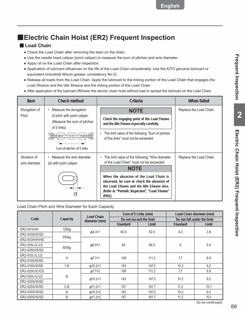
69
2
Item Check method Criteria When failed
Elongation of Pitch
Measure the elongation • of pitch with point caliper. (Measure the sum of pitches of 5 links)
Check the engaging point of the Load Sheave and the Idle Sheave especially carefully.
NOTE
The limit value of the following “Sum of pitches • of fi ve links” must not be exceeded.
Replace the Load Chain.
Abrasion of wire diameter
Measure the wire diameter • (d) with point caliper.
d
The limit value of the following “Wire diameter • of the Load Chain” must not be exceeded.
When the abrasion of the Load Chain is observed, be sure to check the abrasion of the Load Sheave and the Idle Sheave also. (Refer to “Periodic Inspection”, “Load Sheave” (P81).)
NOTE
Replace the Load Chain.
Sum of pitches of 5 links
Electric Chain Hoist (ER2) Frequent Inspection ■Load Chain ■
Check the Load Chain after removing the stain on the chain. ●Use the needle head caliper (point caliper) to measure the sum of pitches and wire diameter. ●Apply oil on the Load Chain after inspection. ●Application of lubricant influences on the life of the Load Chain considerably. Use the KITO genuine lubricant or ●equivalent (industrial lithium grease: consistency No.0)Release all loads from the Load Chain. Apply the lubricant to the linking portion of the Load Chain that engages the ●Load Sheave and the Idle Sheave and the linking portion of the Load Chain.After application of the lubricant lift/lower the electric chain hoist without load to spread the lubricant on the Load Chain. ●
Load Chain Pitch and Wire Diameter for Each Capacity
Code Capacity Load Chain diameter (mm)
Sum of 5 Links (mm) Load Chain diameter (mm)Do not exceed the limit Do not fall under the limit
Standard Limit Standard LimitER2-001H/IH 125kg
4.3×1 60.5 62.5 4.3 3.9ER2-003S/IS/SD
250kgER2-003H/IH/HD
6.0×1 84 86.5 6 5.4ER2-005L/IL/LD500kg
ER2-005S/IS/SDER2-010L/IL/LD
1t 7.7×1 108 111.2 7.7 6.9ER2-010S/IS/SDER2-015S/IS/SD 1.5t 10.2×1 143 147.2 10.2 9.2ER2-020C/IC/CD
2t7.7×2 108 111.2 7.7 6.9
ER2-020L/IL/LD10.2×1 143 147.2 10.2 9.2
ER2-020S/IS/SDER2-025S/IS/SD 2.5t 11.2×1 157 161.7 11.2 10.1ER2-030S/IS/SD 3t 10.2×2 143 147.2 10.2 9.2ER2-050S/IS/SD 5t 11.2×2 157 161.7 11.2 10.1
Frequent InspectionElectric C
hain Hoist (ER
2) Frequent Inspection
(to be continued)

70
Chapter 2 Inspection
2
Item Check method Criteria When failed
Opening and Abrasion of the Hook
Check visually and measure • with vernier caliper.
b
c
a
Embossed markCompare the dimensions of a, b •and c with those at purchasing. Check that they are within the criteria.
The use of the Hooks with these dimensions exceeding the criteria may result in bodily injury or property damage.
Mandatory
CAUTION
Measured value (mm) Limit valueDimension a Not to exceed the dimension at purchasingDimension b
Abrasion not to exceed 5%Dimension c
• Following tables shows the nominal standard values. Please be aware that these values include tolerance because of forging.
ER2 Hook Service Limit (P92) or Criteria
Replace the Hook.
Deformation, Flaw, Corrosion
Check visually.• No deformation such as bend or twist• No deep cut• No loosened bolt or not, or their fall off• No considerable corrosion• No attachment of foreign matter such as • sputter
Replace the Hook.
Frequent Inspection (continued)
Code Capacity
Dimension a (mm) Dimension b (mm) Dimension c (mm)
Standard Standard Limit value Standard Limit
valueER2-001H/IH/HD 125kg
45.0 17.5 16.6 23.5 22.3ER2-003S/IS/H/IH/HD 250kgER2-005L/IL/LD 500kgER2-005S/IS/SDER2-010L/IL/LD 1t 50.0 22.5 21.4 31.0 29.5ER2-010S/IS/SDER2-015S/IS/SD 1.5t 60.0 26.5 25.2 36.5 34.7ER2-020L/IL/LD 2t 69.0 31.5 29.9 43.5 41.3ER2-020S/IS/SDER2-025S/IS/SD 2.5tER2-030S/IS/SD 3t 73.0 34.5 32.8 47.5 45.1ER2-050S/IS/SD 5t 83.0 42.5 40.4 56.0 53.2
Top Hook, Bottom Hook ■
Elec
tric
Cha
in H
oist
(ER
2) F
requ
ent I
nspe
ctio
nFr
eque
nt In
spec
tion
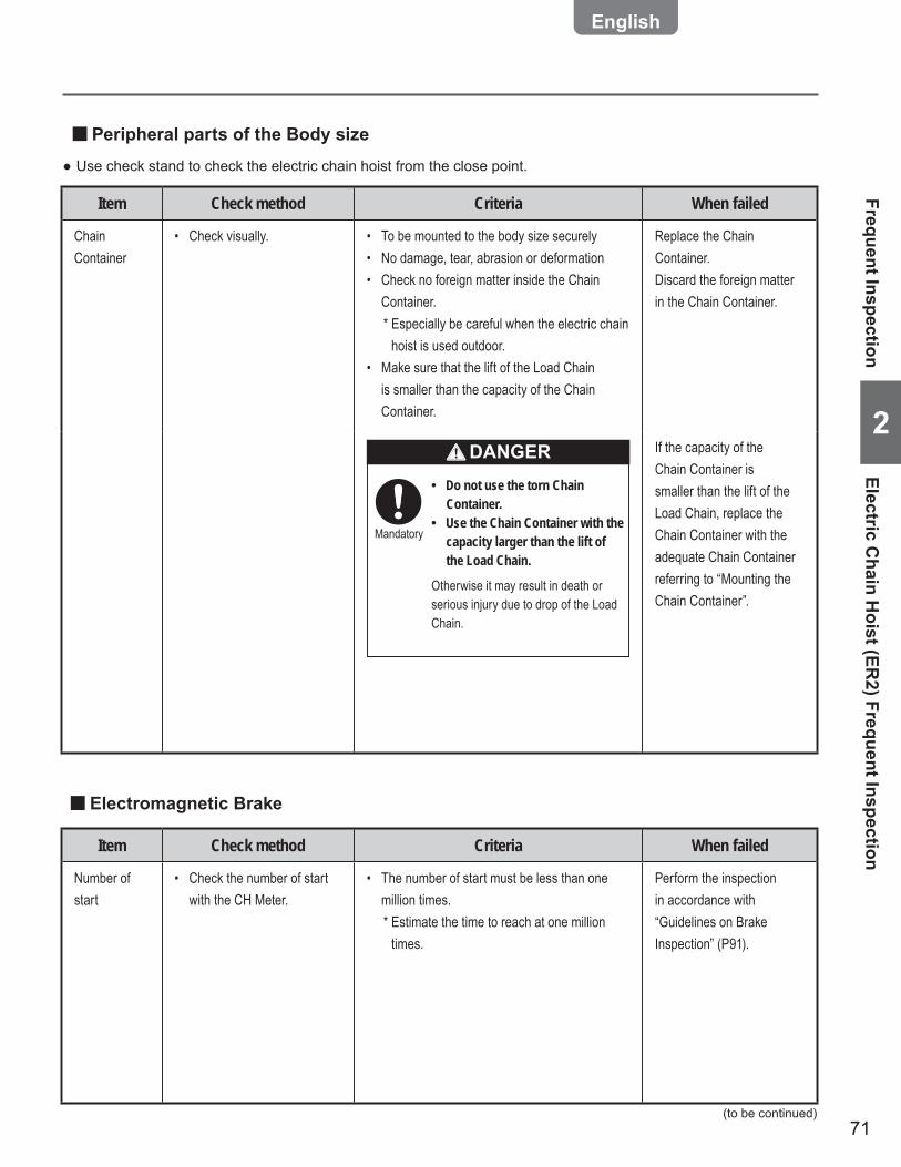
71
2
Use check stand to check the electric chain hoist from the close point. ●
Item Check method Criteria When failed
Chain Container
Check visually.• To be mounted to the body size securely• No damage, tear, abrasion or deformation• Check no foreign matter inside the Chain • Container.* Especially be careful when the electric chain
hoist is used outdoor. Make sure that the lift of the Load Chain • is smaller than the capacity of the Chain Container.
Replace the Chain Container.Discard the foreign matter in the Chain Container.
Do not use the torn Chain •Container.Use the Chain Container with the •capacity larger than the lift of the Load Chain.
Otherwise it may result in death or serious injury due to drop of the Load Chain.
Mandatory
DANGER If the capacity of the Chain Container is smaller than the lift of the Load Chain, replace the Chain Container with the adequate Chain Container referring to “Mounting the Chain Container”.
Peripheral parts of the Body size ■
Item Check method Criteria When failed
Number of start
Check the number of start • with the CH Meter.
The number of start must be less than one • million times.* Estimate the time to reach at one million
times.
Perform the inspection in accordance with “Guidelines on Brake Inspection” (P91).
Electromagnetic Brake ■
Frequent InspectionElectric C
hain Hoist (ER
2) Frequent Inspection
(to be continued)
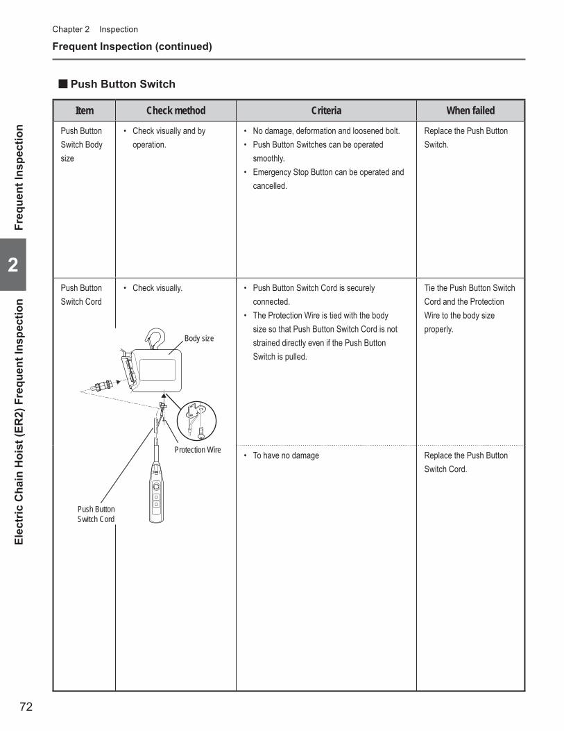
72
Chapter 2 Inspection
2
Frequent Inspection (continued)
Item Check method Criteria When failed
Push Button Switch Body size
Check visually and by • operation.
No damage, deformation and loosened bolt.• Push Button Switches can be operated • smoothly. Emergency Stop Button can be operated and • cancelled.
Replace the Push Button Switch.
Push Button Switch Cord
Check visually.• Push Button Switch Cord is securely • connected. The Protection Wire is tied with the body • size so that Push Button Switch Cord is not strained directly even if the Push Button Switch is pulled.
Tie the Push Button Switch Cord and the Protection Wire to the body size properly.
To have no damage• Replace the Push Button Switch Cord.
Push Button Switch Cord
Body size
Protection Wire
Push Button Switch ■
Elec
tric
Cha
in H
oist
(ER
2) F
requ
ent I
nspe
ctio
nFr
eque
nt In
spec
tion
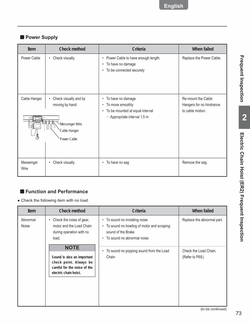
73
2
Item Check method Criteria When failed
Power Cable Check visually.• Power Cable to have enough length.• To have no damage• To be connected securely•
Replace the Power Cable.
Cable Hanger Check visually and by • moving by hand.
To have no damage• To move smoothly• To be mounted at equal interval • ··· Appropriate interval 1.5 m
Re-mount the Cable Hangers for no hindrance to cable motion.
Messenger Wire
Check visually.• To have no sag• Remove the sag.
Messenger Wire
Power Cable
Cable Hanger
Power Supply ■
Item Check method Criteria When failed
Abnormal Noise
Check the noise of gear, • motor and the Load Chain during operation with no load.
Sound is also an important check point . Always be careful for the noise of the electric chain hoist.
NOTE
To sound no irrotating noise• To sound no howling of motor and scraping • sound of the BrakeTo sound no abnormal noise•
Replace the abnormal part.
To sound no popping sound from the Load • Chain
Check the Load Chain. (Refer to P69.)
Check the following item with no load. ●
Function and Performance ■
(to be continued)
Frequent InspectionElectric C
hain Hoist (ER
2) Frequent Inspection
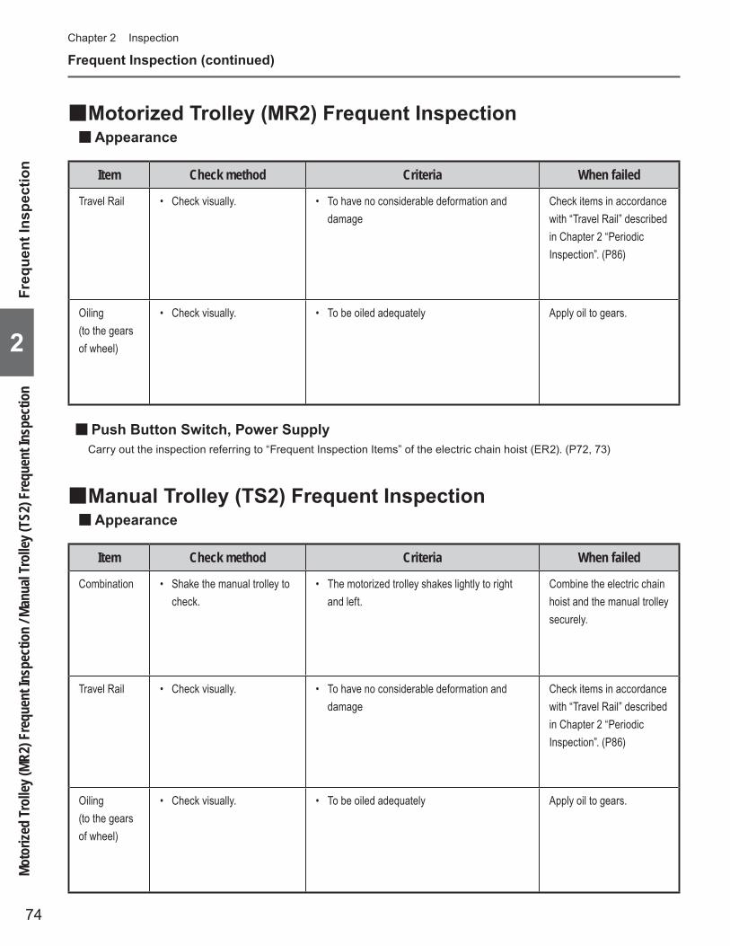
74
Chapter 2 Inspection
2
Frequent Inspection (continued)
Manual Trolley (TS2) Frequent Inspection ■Appearance ■
Item Check method Criteria When failed
Travel Rail Check visually.• To have no considerable deformation and • damage
Check items in accordance with “Travel Rail” described in Chapter 2 “Periodic Inspection”. (P86)
Oiling (to the gears of wheel)
Check visually.• To be oiled adequately• Apply oil to gears.
Motorized Trolley (MR2) Frequent Inspection ■Appearance ■
Item Check method Criteria When failed
Combination Shake the manual trolley to • check.
The motorized trolley shakes lightly to right • and left.
Combine the electric chain hoist and the manual trolley securely.
Travel Rail Check visually.• To have no considerable deformation and • damage
Check items in accordance with “Travel Rail” described in Chapter 2 “Periodic Inspection”. (P86)
Oiling (to the gears of wheel)
Check visually.• To be oiled adequately• Apply oil to gears.
Push Button Switch, Power Supply ■Carry out the inspection referring to “Frequent Inspection Items” of the electric chain hoist (ER2). (P72, 73)
Moto
rized
Trol
ley (M
R2) F
requ
ent I
nspe
ctio
n / M
anua
l Tro
lley (
TS2)
Fre
quen
t Ins
pect
ion
Freq
uent
Insp
ectio
n

75
2
Disassemble the electric chain hoist and check that it is assembled correctly without abnormal parts. ●Refer to Appendix “Technical Material” (P122) for the structure of the product and the name of each part. ●
Put the electric chain hoist on the floor or work bench when inspecting the electric chain hoist. •After completion of the periodic inspection, perform the functional check and make sure that the electric chain •hoist operates correctly.· Wear insulating gloves when measuring voltage.· When measuring the electric characteristics (insulation resistance, but except voltage measurement), turn off the power.
Failure to comply above instructions may result in death or serious injury.
Mandatory
NOTEWhen performing the periodic inspection, carry out the daily inspection at the same time.
General Matters on Handling the Dual Speed VFD Model ■
Do not change the VFD parameters. •When parameters need to be changed, ask our distributors nearest to the customer or KITO.Do not carry out the work such as maintenance and inspection within 5 minutes after power off. •Wait for the completion of discharging of the capacitor inside the VFD.Do not touch the controller cover as it becomes hot during operation. •Do not touch the controller cover until about 30 minutes elapsed after the stop of operation. •USE KITO genuine VFD. •The VFD requires the special specification for KITO. Be sure to use genuine VFD.Do not change the connection of the VFD. •When the wires were removed for any reason, connect them again correctly checking the wiring diagram inside the controller cover.Do not carry out withstand voltage test of a circuit while the VFD is connected. •Do not turn off the power while operating. •
Failure to comply with these instructions may result in death or serious injury and the damage of VFD.
Prohibited
General Matters on Periodic Inspection ■
Periodic Inspection
Periodic InspectionGeneral Matters on Periodic Inspection / General Matters on Handling the Dual Speed VFD Model
(to be continued)
DANGER
DANGER

76
Chapter 2 Inspection
2
Periodic Inspection (continued)
Peripheral parts of the Body size ■
Item Check method Criteria When failed
Number of start
Check the number of start • with the CH Meter.
Number of start must not exceed the • guidelines for replacement.
Replace the Top Hook and Bottom Hook.
Item Check method Criteria When failed
Chain Guide A
Check visually.•
Chain Guide A
To have no apparent abrasion, deformation • and damage To have no fl aw due to hitting by the Load • Chain
The flaw due to hitting is caused •by wrong use such as lifting a load in an inclined direction. If the abrasion is observed on the Chain Guide, the Load Chain may be worn also. Refer to the item of Load Chain Abrasion and check the abrasion.
Neglecting the check of the Load Chain abrasion may result in bodily injury or property damage.
CAUTION
Mandatory
Replace the Chain Guide A.
Electric Chain Hoist (ER2) Periodic Inspection ■Top Hook, Bottom Hook ■
Elec
tric
Cha
in H
oist
(ER
2) P
erio
dic
Insp
ectio
nPe
riodi
c In
spec
tion
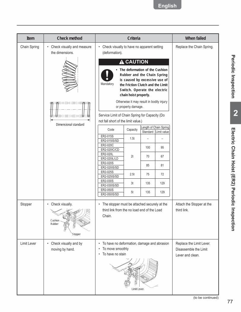
77
2
Item Check method Criteria When failed
Chain Spring Check visually and measure • the dimensions.
Dimensional standard
Check visually to have no apparent setting • (deformation).
The deformation of the Cushion •Rubber and the Chain Spring is caused by excessive use of the Friction Clutch and the Limit Switch. Operate the electric chain hoist properly.
Otherwise it may result in bodily injury or property damage.
CAUTION
Mandatory
Service Limit of Chain Spring for Capacity (Do not fall short of the limit value.)
Code Capacity Length of Chain SpringStandard Limit value
ER2-015S 1.5t – –ER2-015IS/SDER2-020C
2t
100 95ER2-020IC/CDER2-020L 70 67ER2-020IL/LDER2-020S 85 81ER2-020IS/SDER2-025S 2.5t 75 72ER2-025IS/SDER2-030S 3t 135 129ER2-030IS/SDER2-050S 5t 135 129ER2-050IS/SD
Replace the Chain Spring.
Stopper Check visually.•
Stopper
Cushion Rubber
The stopper must be attached securely at the • third link from the no load end of the Load Chain.
Attach the Stopper at the third link.
Limit Lever Check visually and by • moving by hand.
To have no deformation, damage and abrasion• To move smoothly• To have no stain•
Limit Lever.
Replace the Limit Lever.Disassemble the Limit Lever and clean.
Periodic InspectionElectric C
hain Hoist (ER
2) Periodic Inspection
(to be continued)
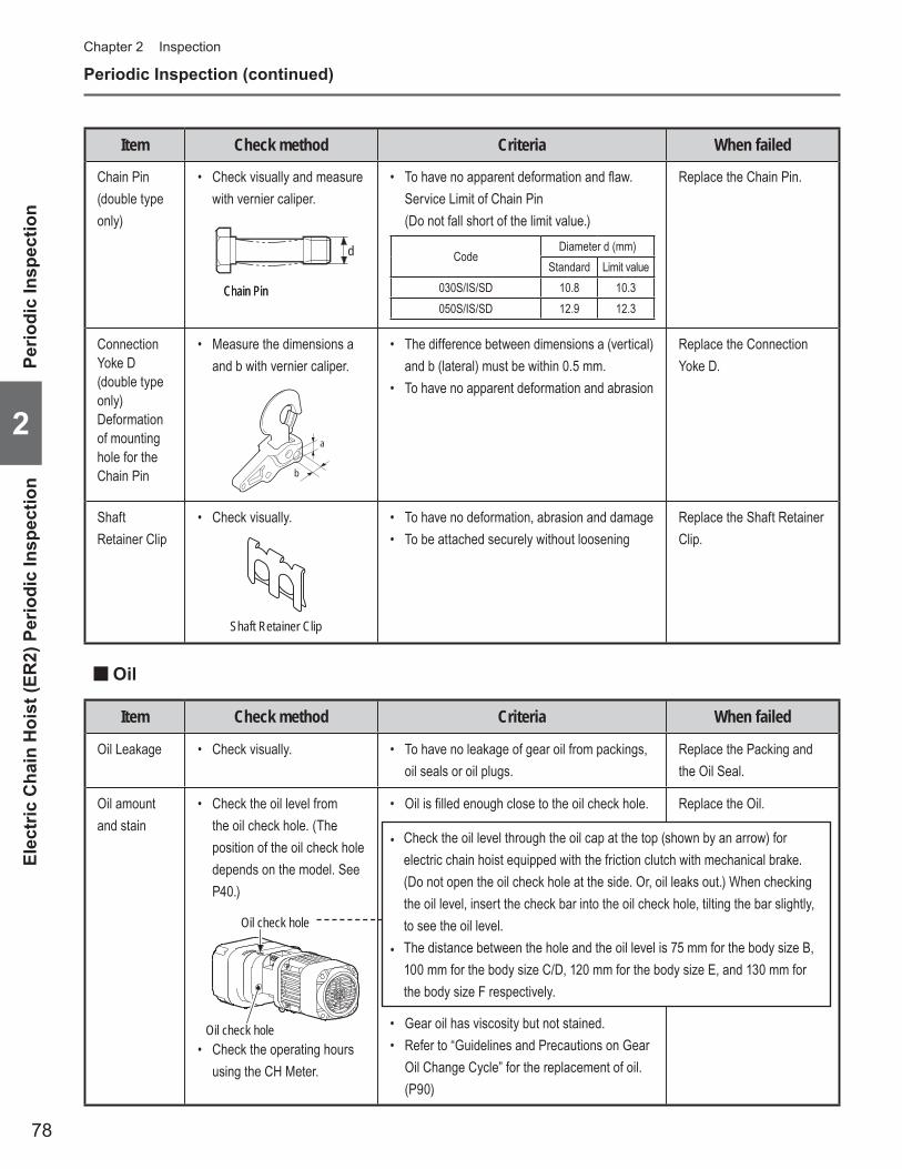
78
Chapter 2 Inspection
2
Periodic Inspection (continued)
Item Check method Criteria When failed
Chain Pin (double type only)
Check visually and measure • with vernier caliper.
d
Chain PinChain Pin
To have no apparent deformation and fl aw.• Service Limit of Chain Pin (Do not fall short of the limit value.)
CodeDiameter d (mm)
Standard Limit value030S/IS/SD 10.8 10.3050S/IS/SD 12.9 12.3
Replace the Chain Pin.
Connection Yoke D (double type only)Deformation of mounting hole for the Chain Pin
Measure the dimensions a • and b with vernier caliper.
b
a
The difference between dimensions a (vertical) • and b (lateral) must be within 0.5 mm. To have no apparent deformation and abrasion•
Replace the Connection Yoke D.
Shaft Retainer Clip
Check visually.•
Shaft Retainer Clip
To have no deformation, abrasion and damage• To be attached securely without loosening•
Replace the Shaft Retainer Clip.
Item Check method Criteria When failed
Oil Leakage Check visually.• To have no leakage of gear oil from packings, • oil seals or oil plugs.
Replace the Packing and the Oil Seal.
Oil amount and stain
Check the oil level from • the oil check hole. (The position of the oil check hole depends on the model. See P40.)
Oil check hole
Oil check hole
Check the operating hours • using the CH Meter.
Oil is fi lled enough close to the oil check hole.•
Gear oil has viscosity but not stained.• Refer to “Guidelines and Precautions on Gear • Oil Change Cycle” for the replacement of oil. (P90)
Replace the Oil.
Oil ■
Check the oil level through the oil cap at the top (shown by an arrow) for • electric chain hoist equipped with the friction clutch with mechanical brake. (Do not open the oil check hole at the side. Or, oil leaks out.) When checking the oil level, insert the check bar into the oil check hole, tilting the bar slightly, to see the oil level.The distance between the hole and the oil level is 75 mm for the body size B, • 100 mm for the body size C/D, 120 mm for the body size E, and 130 mm for the body size F respectively.
Elec
tric
Cha
in H
oist
(ER
2) P
erio
dic
Insp
ectio
nPe
riodi
c In
spec
tion
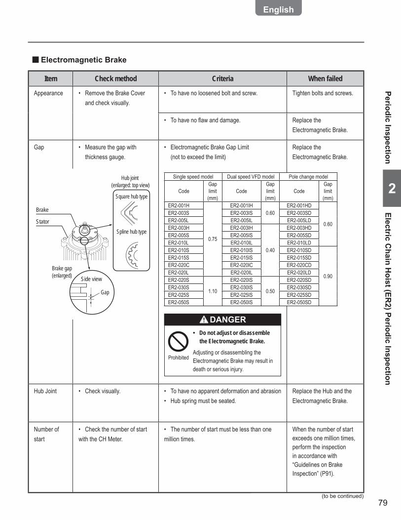
79
2
Item Check method Criteria When failed
Appearance Remove the Brake Cover • and check visually.
To have no loosened bolt and screw.• Tighten bolts and screws.
To have no fl aw and damage.• Replace the Electromagnetic Brake.
Gap Measure the gap with • thickness gauge.
Electromagnetic Brake Gap Limit • (not to exceed the limit)
Single speed model Dual speed VFD model Pole change model
CodeGap limit (mm)
CodeGap limit (mm)
CodeGap limit (mm)
ER2-001H
0.75
ER2-001IH0.60
ER2-001HD
0.60
ER2-003S ER2-003IS ER2-003SDER2-005L ER2-005IL ER2-005LDER2-003H ER2-003IH
0.40
ER2-003HDER2-005S ER2-005IS ER2-005SDER2-010L ER2-010IL ER2-010LDER2-010S ER2-010IS ER2-010SD
0.90
ER2-015S ER2-015IS ER2-015SDER2-020C ER2-020IC ER2-020CDER2-020L ER2-020IL ER2-020LDER2-020S
1.10
ER2-020IS
0.50
ER2-020SDER2-030S ER2-030IS ER2-030SDER2-025S ER2-025IS ER2-025SDER2-050S ER2-050IS ER2-050SD
Do not adjust or disassemble •the Electromagnetic Brake.
Adjusting or disassembling the Electromagnetic Brake may result in death or serious injury.
Prohibited
DANGER
Replace the Electromagnetic Brake.
Hub Joint Check visually.• To have no apparent deformation and abrasion• Hub spring must be seated.•
Replace the Hub and the Electromagnetic Brake.
Number of start
Check the number of start • with the CH Meter.
The number of start must be less than one • million times.
When the number of start exceeds one million times, perform the inspection in accordance with “Guidelines on Brake Inspection” (P91).
Brake
Stator
Side view
Gap
Brake gap (enlarged)
Square hub type
Hub joint (enlarged: top view)
Spline hub type
Electromagnetic Brake ■
Periodic InspectionElectric C
hain Hoist (ER
2) Periodic Inspection
(to be continued)

80
Chapter 2 Inspection
2
Periodic Inspection (continued)
Item Check method Criteria When failed
Bearing Check visually and rotate • the Bearing by hand. Check the operating hours • with the CH Meter.
To have no harmful defi ciency such as • apparent abrasion, fl aw and damage. To rotate smoothly. The operating hours must not exceed • the guidelines for replacement. (Refer to Guidelines on Bearing Replacement (P92).)
Replace the Bearing.
Load Gear, Gear B, Pinion
Disassemble the electric • chain hoist and check the arrowed portion. Check the operating hours • using the CH Meter.
Spline
Motor shaft
Rotor
To have no apparent abrasion• To have no damage• Operating hours not to exceed the guidelines • for replacement (Refer to “Guidelines on Gear Parts Replacement” (P91).)
Replace the Gear.• Replace the Pinion.• Replace the oil at the • same time.
Friction Clutch
Check visually• Check the operating hours • using the CH Meter.
To have no apparent abrasion, deformation, • fl aw and damage. Pawl must have no apparent deformation and • abrasion.
Do not adjust or disassemble the •Friction Clutch.
Adjusting and disassembling the Friction Clutch may result in death or serious injury.
Prohibited
DANGER
Operating hours not to exceed the guidelines • for replacement (Refer to “Guidelines on Gear Parts Replacement” (P91).)
Replace the Friction Clutch.
Driving Mechanism ■
Elec
tric
Cha
in H
oist
(ER
2) P
erio
dic
Insp
ectio
nPe
riodi
c In
spec
tion
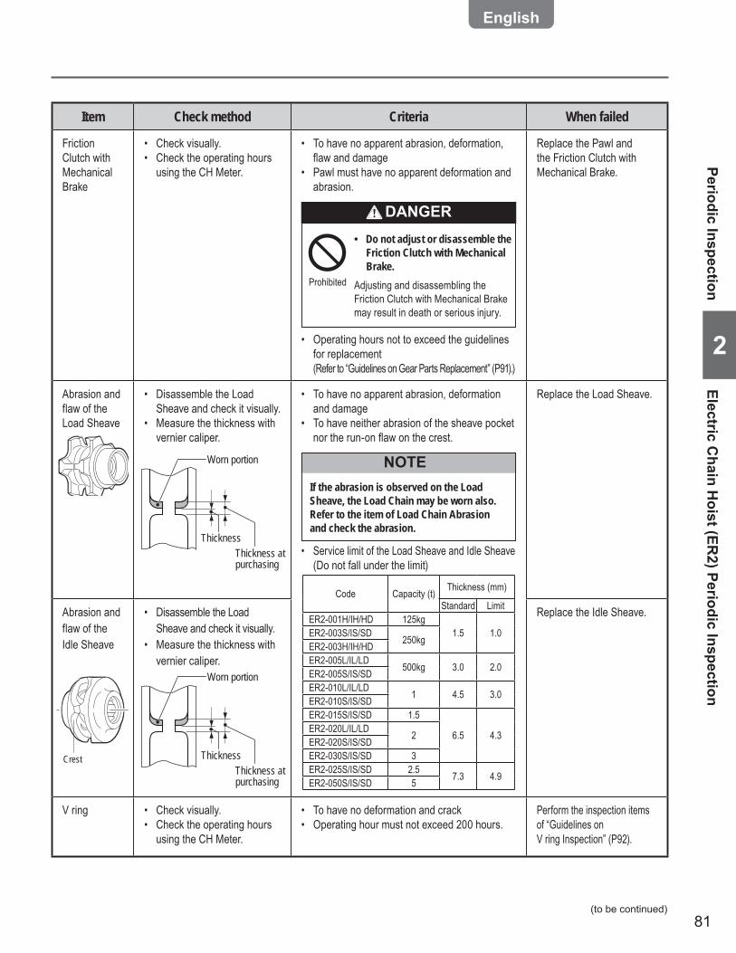
81
2
Item Check method Criteria When failed
Friction Clutch with Mechanical Brake
Check visually.• Check the operating hours • using the CH Meter.
To have no apparent abrasion, deformation, • fl aw and damage Pawl must have no apparent deformation and • abrasion.
Do not adjust or disassemble the •Friction Clutch with Mechanical Brake.
Adjusting and disassembling the Friction Clutch with Mechanical Brake may result in death or serious injury.
Prohibited
DANGER
Operating hours not to exceed the guidelines • for replacement (Refer to “Guidelines on Gear Parts Replacement” (P91).)
Replace the Pawl and the Friction Clutch with Mechanical Brake.
Abrasion and flaw of the Load Sheave
Disassemble the Load • Sheave and check it visually. Measure the thickness with • vernier caliper.
Worn portion
Thickness at purchasing
Thickness
To have no apparent abrasion, deformation • and damage To have neither abrasion of the sheave pocket • nor the run-on fl aw on the crest.
If the abrasion is observed on the Load Sheave, the Load Chain may be worn also. Refer to the item of Load Chain Abrasion and check the abrasion.
NOTE
Service limit of the Load Sheave and Idle Sheave • (Do not fall under the limit)
Code Capacity (t) Thickness (mm)
Standard LimitER2-001H/IH/HD 125kg
1.5 1.0ER2-003S/IS/SD 250kgER2-003H/IH/HDER2-005L/IL/LD 500kg 3.0 2.0ER2-005S/IS/SDER2-010L/IL/LD 1 4.5 3.0ER2-010S/IS/SDER2-015S/IS/SD 1.5
6.5 4.3ER2-020L/IL/LD 2ER2-020S/IS/SDER2-030S/IS/SD 3ER2-025S/IS/SD 2.5 7.3 4.9ER2-050S/IS/SD 5
Replace the Load Sheave.
Abrasion and flaw of the Idle Sheave
Crest
Disassemble the Load • Sheave and check it visually. Measure the thickness with • vernier caliper.
Worn portion
Thickness at purchasing
Thickness
Replace the Idle Sheave.
V ring Check visually.• Check the operating hours • using the CH Meter.
To have no deformation and crack• Operating hour must not exceed 200 hours.•
Perform the inspection items of “Guidelines on V ring Inspection” (P92).
Periodic InspectionElectric C
hain Hoist (ER
2) Periodic Inspection
(to be continued)
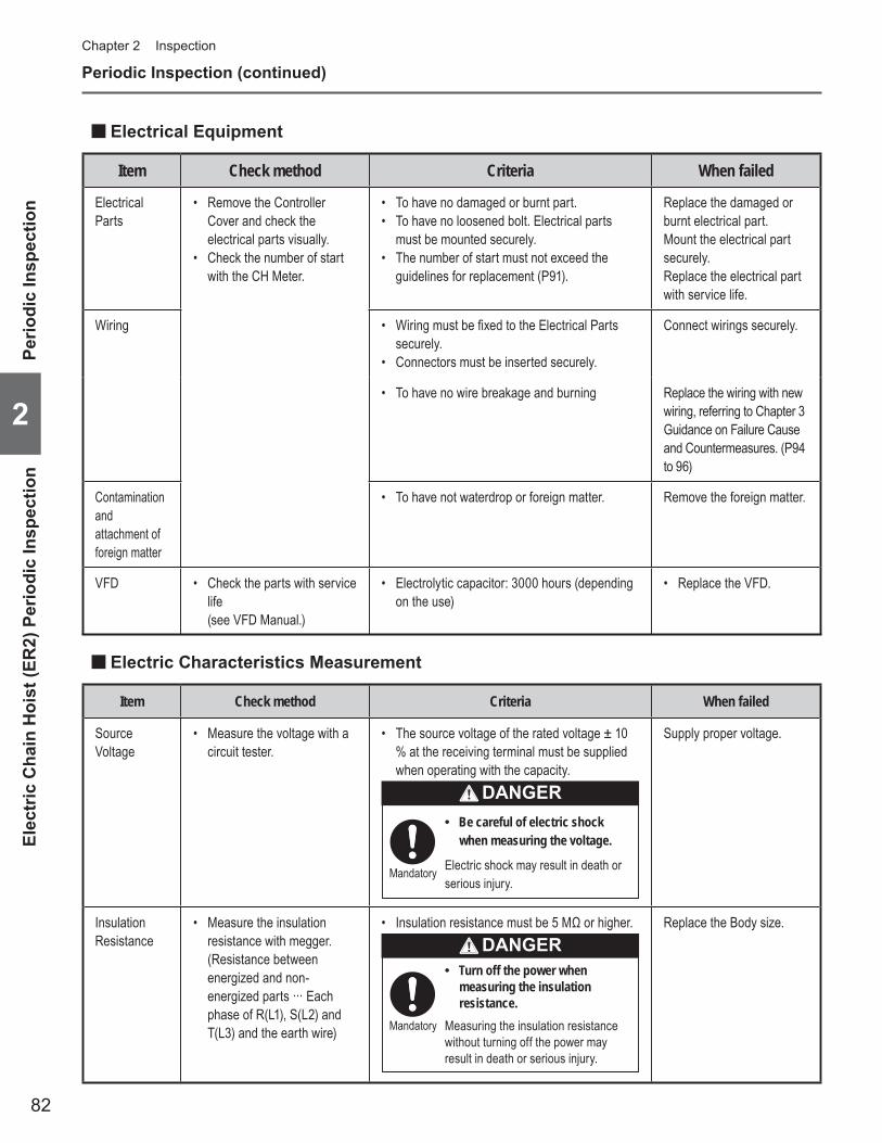
82
Chapter 2 Inspection
2
Periodic Inspection (continued)
Item Check method Criteria When failed
Electrical Parts
Remove the Controller • Cover and check the electrical parts visually. Check the number of start • with the CH Meter.
To have no damaged or burnt part.• To have no loosened bolt. Electrical parts • must be mounted securely. The number of start must not exceed the • guidelines for replacement (P91).
Replace the damaged or burnt electrical part.Mount the electrical part securely.Replace the electrical part with service life.
Wiring Wiring must be fi xed to the Electrical Parts • securely.Connectors must be inserted securely.•
Connect wirings securely.
To have no wire breakage and burning• Replace the wiring with new wiring, referring to Chapter 3 Guidance on Failure Cause and Countermeasures. (P94 to 96)
Contamination and attachment of foreign matter
To have not waterdrop or foreign matter.• Remove the foreign matter.
VFD Check the parts with service • life (see VFD Manual.)
Electrolytic capacitor: 3000 hours (depending • on the use)
Replace the VFD.•
Electrical Equipment ■
Item Check method Criteria When failed
Source Voltage
Measure the voltage with a • circuit tester.
The source voltage of the rated voltage ± 10 • % at the receiving terminal must be supplied when operating with the capacity.
Be careful of electric shock •when measuring the voltage.
Electric shock may result in death or serious injury.
Mandatory
DANGER
Supply proper voltage.
Insulation Resistance
Measure the insulation • resistance with megger. (Resistance between energized and non-energized parts ··· Each phase of R(L1), S(L2) and T(L3) and the earth wire)
Insulation resistance must be 5 MΩ or higher.•
Turn off the power when •measuring the insulation resistance.
Measuring the insulation resistance without turning off the power may result in death or serious injury.
Mandatory
DANGERReplace the Body size.
Electric Characteristics Measurement ■
Elec
tric
Cha
in H
oist
(ER
2) P
erio
dic
Insp
ectio
nPe
riodi
c In
spec
tion
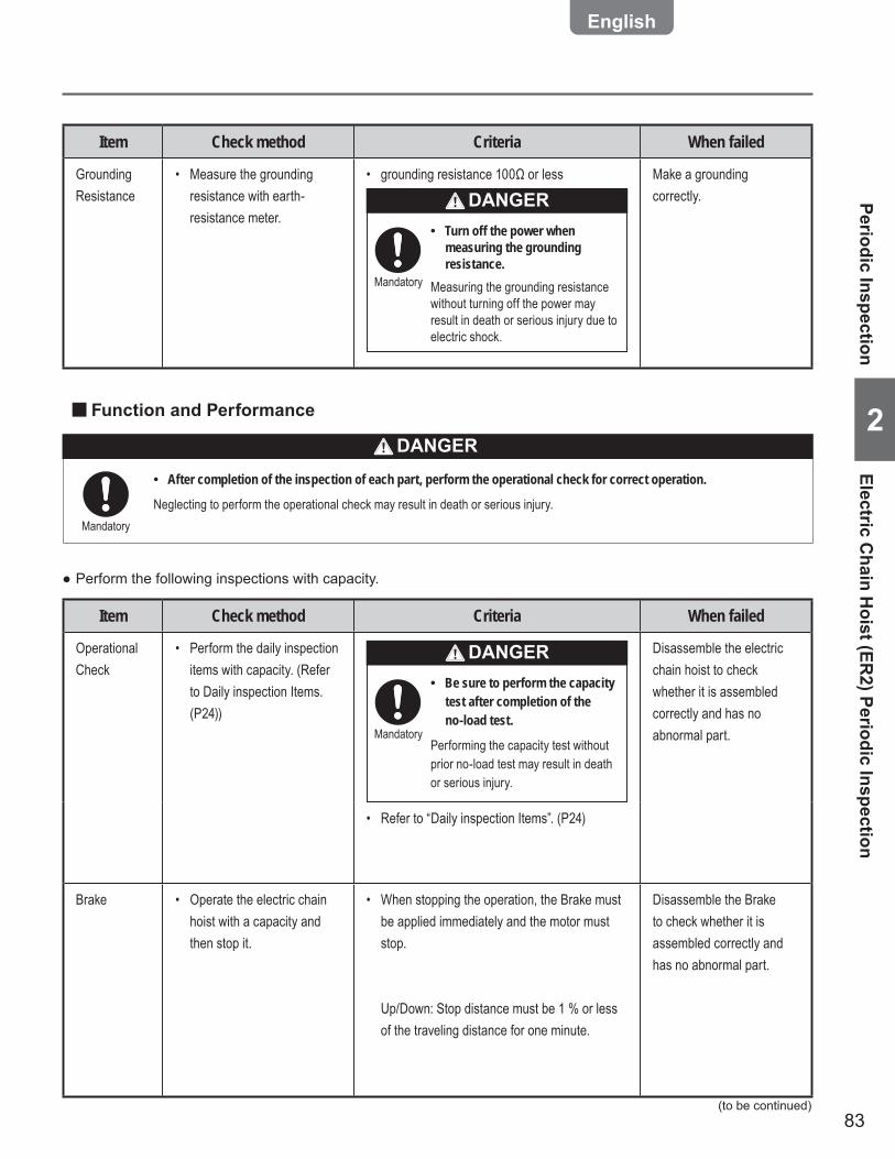
83
2
Item Check method Criteria When failed
Operational Check
Perform the daily inspection • items with capacity. (Refer to Daily inspection Items. (P24))
Be sure to perform the capacity •test after completion of the no-load test.
Performing the capacity test without prior no-load test may result in death or serious injury.
Mandatory
DANGER Disassemble the electric chain hoist to check whether it is assembled correctly and has no abnormal part.
Refer to “Daily inspection Items”. (P24)•
Brake Operate the electric chain • hoist with a capacity and then stop it.
When stopping the operation, the Brake must • be applied immediately and the motor must stop.
Up/Down: Stop distance must be 1 % or less of the traveling distance for one minute.
Disassemble the Brake to check whether it is assembled correctly and has no abnormal part.
After completion of the inspection of each part, perform the operational check for correct operation. •
Neglecting to perform the operational check may result in death or serious injury.
Item Check method Criteria When failed
Grounding Resistance
Measure the grounding • resistance with earth-resistance meter.
grounding resistance 100Ω or less•
Turn off the power when •measuring the grounding resistance.
Measuring the grounding resistance without turning off the power may result in death or serious injury due to electric shock.
Mandatory
DANGERMake a grounding correctly.
Function and Performance ■
Mandatory
Perform the following inspections with capacity. ●
Periodic InspectionElectric C
hain Hoist (ER
2) Periodic Inspection
(to be continued)
DANGER

84
Chapter 2 Inspection
2
Periodic Inspection (continued)
Item Check method Criteria When failed
Wheel Check visually.• Measure dimensions D and • d with vernier caliper.
d D
Wheel for I · H beam (0.5 to 5 t)Wheel for I · H beam (0.5 to 5 t)
Measure the outer diameter with vernier caliper.
To have no considerable deformation • and damageAbrasion Limit of Wheel • (Do not fall under the limit.)
Capacity (t) Beam type D (mm) d (mm)Standard Limit Standard Limit
125, 250, 500kg I · H 95 91 91.5 87.51 I · H 95 91 91.5 87.5
1.5, 2 I · H 110 105 106 1012.5, 3 I · H 125 118 121 114
5 I · H 140 132 135 127
Replace the Wheel.
Side Roller Check visually.• Measure outer diameter of the • worn part with vernier caliper.
Outer diameter
• To have no considerable deformation and damage Abrasion Limit of Side Roller • (Do not fall under the limit.)
Capacity (t) Outer diameter (mm)Standard Limit
125, 250, 500kg 38 371 38 37
1.5, 2 43 422.5, 3 43 42
5 55 54
Replace the Side Roller.
Motorized Trolley (MR2) Periodic Inspection ■Brake ■
Item Check method Criteria When failed
Appearance Disassemble the Brake and • check it visually.
To have no deformation, fl aw and damage on • the Brake Drum and the Motor Cover.
Replace the Part.
To have no deformation and damage on the • Brake Spring.
Replace the Brake Spring.
Abrasion of Brake Pad
Disassemble the Brake and • measure the abrasion.
Trolley Brake Service Limit (Do not fall under the limit.)
Speed Dimension Standard LimitSingle Speed B 32.5 31.0Dual Speed (VFD)Dual Speed (500V Class) B' 36.8 36.3
Replace the Motor Cover.
Brake Pad
Motor Cover
Brake Drum
B’
B
Body size Components ■
Mot
oriz
ed T
rolle
y (M
R2)
Per
iodi
c In
spec
tion
Perio
dic
Insp
ectio
n

85
2
Item Check method Criteria When failed
Lifting Shaft Check visually.• Measure the shaft diameter • with vernier caliper.
Shaft diameter
To have no considerable deformation and • abrasion The shaft with obvious deformation reaches at • the service limit. Abrasion limit of the shaft is 5% of its diameter • respectively.
Replace the Lifting Shaft.
Suspender Check visually.• Measure the diameter of the • hole with vernier caliper.
Hole diameter
The Suspender must be combined securely • with the top pin and the Yoke bolt. Abrasion limit of the hole is 5 % of its diameter.•
Replace the Suspender.
Gear Frame Packing
Check visually.•
Gear Frame Packing
To have no damage and breakage.• Replace the Gear Frame Packing.
Gears and Motor Shaft
Check visually.•
Motor shaft
Rotor
To have no apparent abrasion, deformation • and damage
Replace the Part.
Periodic InspectionM
otorized Trolley (MR
2) Periodic Inspection
(to be continued)
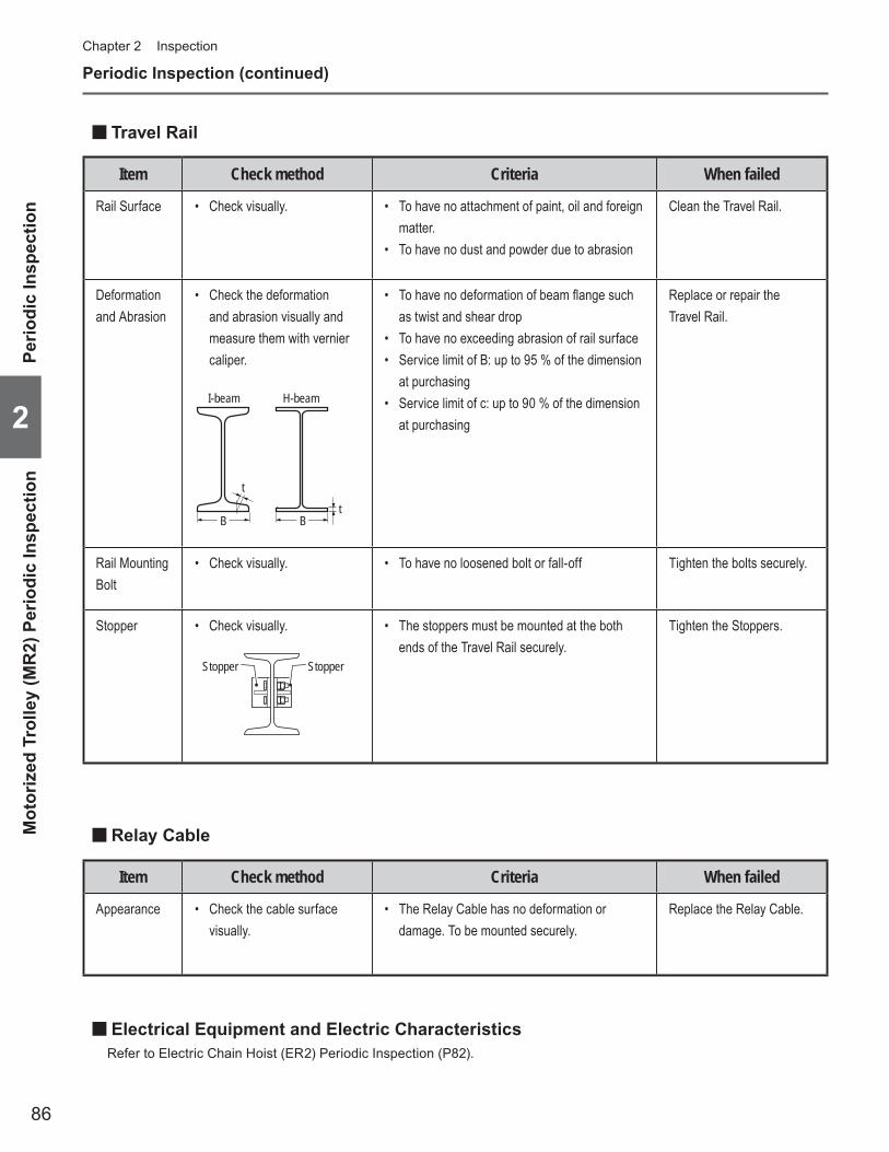
86
Chapter 2 Inspection
2
Periodic Inspection (continued)
Item Check method Criteria When failed
Rail Surface Check visually.• To have no attachment of paint, oil and foreign • matter.To have no dust and powder due to abrasion•
Clean the Travel Rail.
Deformation and Abrasion
Check the deformation • and abrasion visually and measure them with vernier caliper.
I-beam H-beam
B B
tt
To have no deformation of beam fl ange such • as twist and shear drop To have no exceeding abrasion of rail surface• Service limit of B: up to 95 % of the dimension • at purchasing Service limit of c: up to 90 % of the dimension • at purchasing
Replace or repair the Travel Rail.
Rail Mounting Bolt
Check visually.• To have no loosened bolt or fall-off• Tighten the bolts securely.
Stopper Check visually.•
Stopper Stopper
The stoppers must be mounted at the both • ends of the Travel Rail securely.
Tighten the Stoppers.
Travel Rail ■
Item Check method Criteria When failed
Appearance Check the cable surface • visually.
The Relay Cable has no deformation or • damage. To be mounted securely.
Replace the Relay Cable.
Relay Cable ■
Electrical Equipment and Electric Characteristics ■Refer to Electric Chain Hoist (ER2) Periodic Inspection (P82).
Mot
oriz
ed T
rolle
y (M
R2)
Per
iodi
c In
spec
tion
Perio
dic
Insp
ectio
n
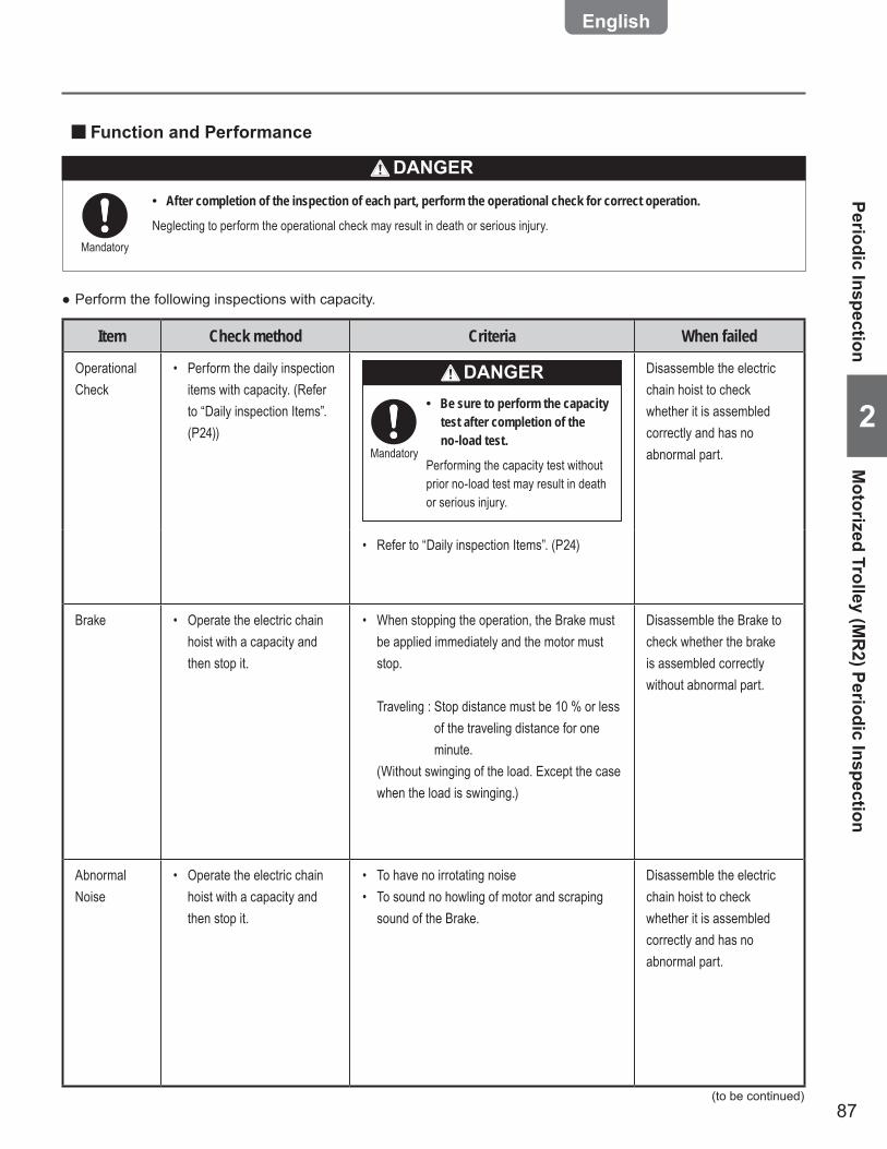
87
2
Item Check method Criteria When failed
Operational Check
Perform the daily inspection • items with capacity. (Refer to “Daily inspection Items”. (P24))
Be sure to perform the capacity •test after completion of the no-load test.
Performing the capacity test without prior no-load test may result in death or serious injury.
Mandatory
DANGER Disassemble the electric chain hoist to check whether it is assembled correctly and has no abnormal part.
Refer to “Daily inspection Items”. (P24)•
Brake Operate the electric chain • hoist with a capacity and then stop it.
When stopping the operation, the Brake must • be applied immediately and the motor must stop.
Traveling : Stop distance must be 10 % or less of the traveling distance for one minute.
(Without swinging of the load. Except the case when the load is swinging.)
Disassemble the Brake to check whether the brake is assembled correctly without abnormal part.
Abnormal Noise
Operate the electric chain • hoist with a capacity and then stop it.
To have no irrotating noise• To sound no howling of motor and scraping • sound of the Brake.
Disassemble the electric chain hoist to check whether it is assembled correctly and has no abnormal part.
After completion of the inspection of each part, perform the operational check for correct operation. •
Neglecting to perform the operational check may result in death or serious injury.
Function and Performance ■
Mandatory
Perform the following inspections with capacity. ●
Periodic InspectionM
otorized Trolley (MR
2) Periodic Inspection
(to be continued)
DANGER

88
Chapter 2 Inspection
2
Periodic Inspection (continued)
Manual Trolley (TSG/TSP) Periodic Inspection ■Body size Components ■
Item Check method Criteria When failed
Wheel Check visually.• Measure dimensions D and • t with vernier caliper.
t
d
0.5~3t0.5~3t 5t5t
D D
Measure the outer diameter • with vernier caliper.
To have no considerable deformation • and damageAbrasion Limit of Wheel • (Do not fall under the limit.)
Capacity D (mm) Flange thickness t (mm)TSP TSG Standard Limit Standard Limit
125, 250, 500kg – 60 58.5 3.2 2.5
1t 125, 250, 500kg, 1t 71 68.5 4 3.3
1.5t, 2t 85 83.5 4.5 3.82.5t, 3t 100 98.5 5 4.3
5t 118 112 9.6 6.7
Replace the Wheel.
Lifting Shaft Check visually.• Measure the shaft diameter • with vernier caliper.
Shaft diameter
To have no considerable deformation and • abrasion The shaft with obvious deformation reaches at • the service limit.
Abrasion limit of the shaft and the hole is 5 % • of its diameter respectively.
Replace the Lifting Shaft.
Suspender Check visually.• Measure the diameter of the • hole with vernier caliper.
Hole diameter
The Suspender must be combined securely • with the top pin and the Yoke bolt. Abrasion limit of the hole is 5 % of its diameter.•
Replace the Suspender.
Item Check method Criteria When failed
Rail Surface Check visually.• To have no attachment of paint, oil and foreign • matter.To have no dust and powder due to abrasion•
Clean the Travel Rail.
Travel Rail ■
Man
ual T
rolle
y (T
SG/T
SP) P
erio
dic
Insp
ectio
nPe
riodi
c In
spec
tion
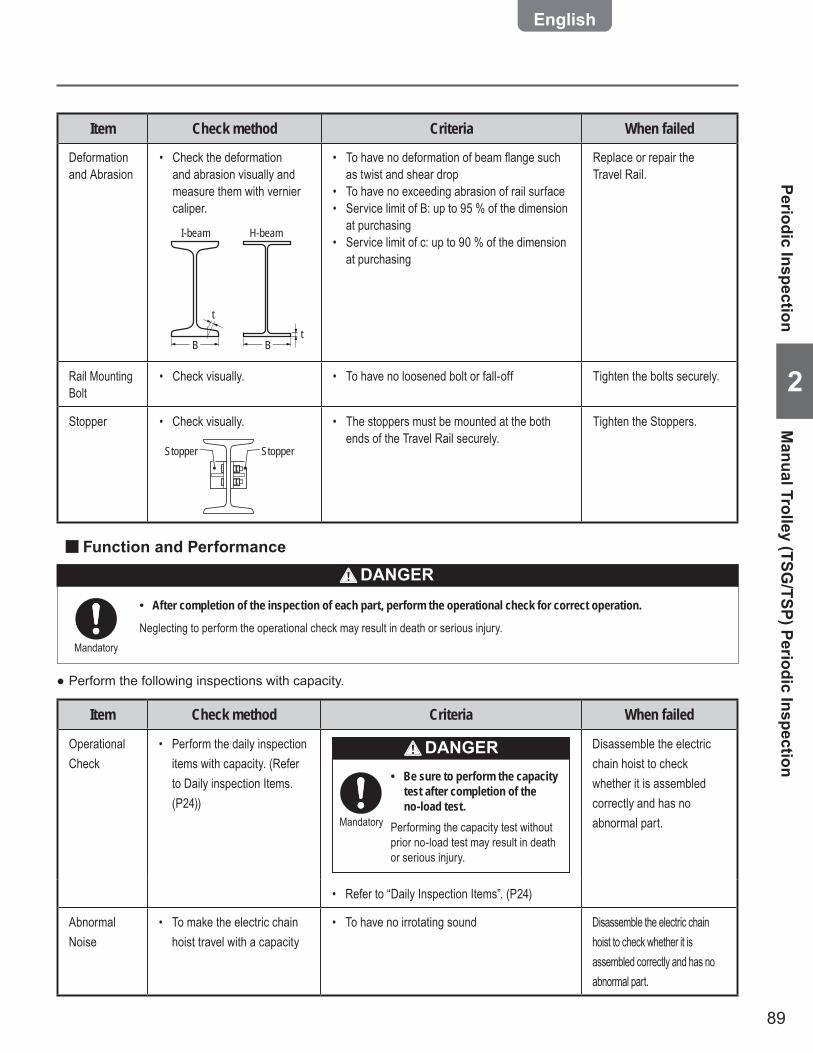
89
2
Item Check method Criteria When failed
Deformation and Abrasion
Check the deformation • and abrasion visually and measure them with vernier caliper.
I-beam H-beam
B B
tt
To have no deformation of beam fl ange such • as twist and shear drop To have no exceeding abrasion of rail surface• Service limit of B: up to 95 % of the dimension • at purchasing Service limit of c: up to 90 % of the dimension • at purchasing
Replace or repair the Travel Rail.
Rail Mounting Bolt
Check visually.• To have no loosened bolt or fall-off• Tighten the bolts securely.
Stopper Check visually.•
Stopper Stopper
The stoppers must be mounted at the both • ends of the Travel Rail securely.
Tighten the Stoppers.
Item Check method Criteria When failed
Operational Check
Perform the daily inspection • items with capacity. (Refer to Daily inspection Items. (P24))
Be sure to perform the capacity •test after completion of the no-load test.
Performing the capacity test without prior no-load test may result in death or serious injury.
Mandatory
DANGER Disassemble the electric chain hoist to check whether it is assembled correctly and has no abnormal part.
Refer to “Daily Inspection Items”. (P24) •
Abnormal Noise
To make the electric chain • hoist travel with a capacity
To have no irrotating sound• Disassemble the electric chain hoist to check whether it is assembled correctly and has no abnormal part.
Function and Performance ■
Perform the following inspections with capacity. ●
Periodic InspectionM
anual Trolley (TSG/TSP) Periodic Inspection
After completion of the inspection of each part, perform the operational check for correct operation. •
Neglecting to perform the operational check may result in death or serious injury.Mandatory
DANGER
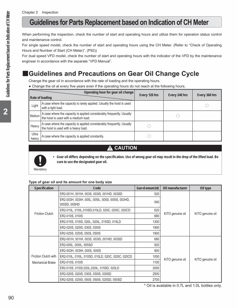
90
Chapter 2 Inspection
2
When performing the inspection, check the number of start and operating hours and utilize them for operation status control and maintenance control.For single speed model, check the number of start and operating hours using the CH Meter. (Refer to “Check of Operating Hours and Number of Start (CH Meter)”. (P92))For dual speed VFD model, check the number of start and operating hours with the indicator of the VFD by the maintenance engineer in accordance with the separate “VFD Manual”.
Guidelines and Precautions on Gear Oil Change Cycle ■Change the gear oil in accordance with the rate of loading and the operating hours.
Change the oil at every five years even if the operating hours do not reach at the following hours. ●Operating hour for gear oil change
Rate of loadingEvery 120 hrs Every 240 hrs Every 360 hrs
Light A case where the capacity is rarely applied. Usually the hoist is used with a light load. ○
Medium A case where the capacity is applied considerably frequently. Usually the hoist is used with a medium load. ○
Heavy A case where the capacity is applied considerably frequently. Usually the hoist is used with a heavy load. ○
Ultra heavy A case where the capacity is applied constantly. ○
Type of gear oil and its amount for one body sizeSpecification Code Gear oil amount (ml) Oil manufacturer Oil type
Friction Clutch
ER2-001H, 001IH, 003S, 003IS, 001HD, 003SD 520
KITO genuine oil KITO genuine oil
ER2-003H, 003IH, 005L, 005IL, 005S, 005IS, 003HD, 005SD, 005HD 540
ER2-010L, 010IL,010SD,010LD, 020C, 020IC, 020CD 620ER2-010S, 010IS 680ER2-015S, 015IS, 020L, 020IL, 015SD, 015LD 1300ER2-020S, 020IS, 030S, 030IS 1900ER2-025S, 025IS, 050S, 050IS 1900
Friction Clutch with
Mechanical Brake
ER2-001H, 001IH, 003S, 003IS, 001HD, 003SD 680
KITO genuine oil KITO genuine oil
ER2-005L, 005IL, 005SD 820ER2-003H, 003IH, 005S, 005IS 900ER2-010L, 010IL, 010SD, 010LD, 020C, 020IC, 020CD 1050ER2-010S, 010IS 1100ER2-015S, 015IS,020L,020IL, 015SD, 020LD 2000ER2-020S, 020IS, 030S, 030IS, 030SD 2500ER2-025S, 025IS, 050S, 050IS, 025SD, 050SD 2700
Guidelines for Parts Replacement based on Indication of CH Meter
Guide
lines fo
r Part
s Repl
aceme
nt bas
ed on
Indica
tion o
f CH M
eter
CAUTIONGear oil differs depending on the specification. Use of wrong gear oil may result in the drop of the lifted load. Be •sure to use the designated gear oil.
Mandatory
* Oil is available in 0.7L and 1.0L bottles only.
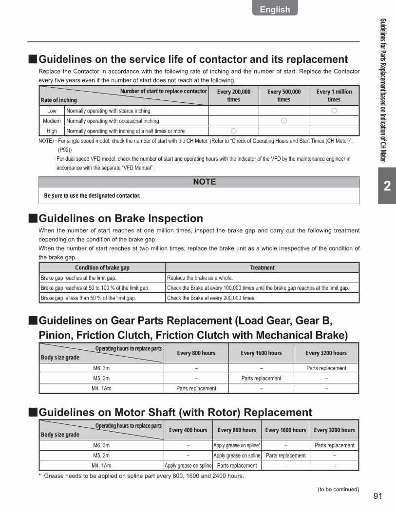
91
2
Guidelines on the service life of contactor and its replacement ■Replace the Contactor in accordance with the following rate of inching and the number of start. Replace the Contactor every five years even if the number of start does not reach at the following.
Number of start to replace contactorRate of inching
Every 200,000 times
Every 500,000 times
Every 1 million times
Low Normally operating with scarce inching ○Medium Normally operating with occasional inching ○
High Normally operating with inching at a half times or more ○NOTE) · For single speed model, check the number of start with the CH Meter. (Refer to “Check of Operating Hours and Start Times (CH Meter)”.
(P92)) · For dual speed VFD model, check the number of start and operating hours with the indicator of the VFD by the maintenance engineer in
accordance with the separate “VFD Manual”.
NOTEBe sure to use the designated contactor.
Guidelines on Brake Inspection ■When the number of start reaches at one million times, inspect the brake gap and carry out the following treatment depending on the condition of the brake gap.When the number of start reaches at two million times, replace the brake unit as a whole irrespective of the condition of the brake gap.
Condition of brake gap TreatmentBrake gap reaches at the limit gap. Replace the brake as a whole.Brake gap reaches at 50 to 100 % of the limit gap. Check the Brake at every 100,000 times until the brake gap reaches at the limit gap.Brake gap is less than 50 % of the limit gap. Check the Brake at every 200,000 times.
Guidelines on Gear Parts Replacement (Load Gear, Gear B, ■Pinion, Friction Clutch, Friction Clutch with Mechanical Brake)
Operating hours to replace partsBody size grade
Every 800 hours Every 1600 hours Every 3200 hours
M6, 3m – – Parts replacementM5, 2m – Parts replacement –
M4, 1Am Parts replacement – –
Guidelines on Motor Shaft (with Rotor) Replacement ■Operating hours to replace parts
Body size gradeEvery 400 hours Every 800 hours Every 1600 hours Every 3200 hours
M6, 3m – Apply grease on spline* – Parts replacementM5, 2m – Apply grease on spline Parts replacement –
M4, 1Am Apply grease on spline Parts replacement – –* Grease needs to be applied on spline part every 800, 1600 and 2400 hours.
Guidelines for Parts Replacement based on Indication of CH Meter
(to be continued)
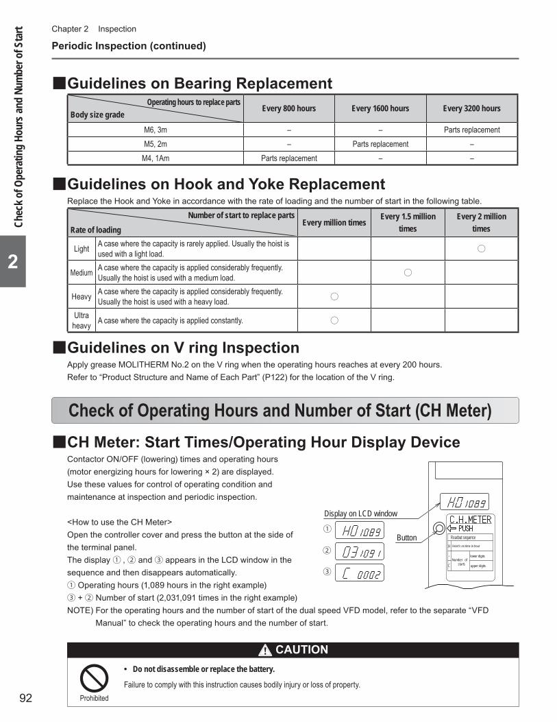
92
Chapter 2 Inspection
2
CH Meter: Start Times/Operating Hour Display Device ■Contactor ON/OFF (lowering) times and operating hours (motor energizing hours for lowering × 2) are displayed.Use these values for control of operating condition and maintenance at inspection and periodic inspection.
<How to use the CH Meter>Open the controller cover and press the button at the side of the terminal panel.The display ① , ② and ③ appears in the LCD window in the sequence and then disappears automatically.① Operating hours (1,089 hours in the right example)③ +② Number of start (2,031,091 times in the right example)NOTE) For the operating hours and the number of start of the dual speed VFD model, refer to the separate “VFD
Manual” to check the operating hours and the number of start.
Check of Operating Hours and Number of Start (CH Meter)
①
②
③
H
lower digits
upper digitsCNumber of
starts
-
Readout sequenceHoist's on time in hour
Display on LCD window
Button
Periodic Inspection (continued)
Guidelines on Bearing Replacement ■Operating hours to replace parts
Body size gradeEvery 800 hours Every 1600 hours Every 3200 hours
M6, 3m – – Parts replacementM5, 2m – Parts replacement –
M4, 1Am Parts replacement – –
Guidelines on Hook and Yoke Replacement ■Replace the Hook and Yoke in accordance with the rate of loading and the number of start in the following table.
Number of start to replace partsRate of loading
Every million timesEvery 1.5 million
timesEvery 2 million
times
Light A case where the capacity is rarely applied. Usually the hoist is used with a light load. ○
Medium A case where the capacity is applied considerably frequently. Usually the hoist is used with a medium load. ○
Heavy A case where the capacity is applied considerably frequently. Usually the hoist is used with a heavy load. ○
Ultra heavy A case where the capacity is applied constantly. ○
Guidelines on V ring Inspection ■Apply grease MOLITHERM No.2 on the V ring when the operating hours reaches at every 200 hours.Refer to “Product Structure and Name of Each Part” (P122) for the location of the V ring.
Chec
k of O
pera
ting
Hour
s and
Num
ber o
f Sta
rt
CAUTIONDo not disassemble or replace the battery. •
Failure to comply with this instruction causes bodily injury or loss of property.Prohibited
93
Chapter 3Troubleshooting
Guidance on Troubleshooting ■ ........................................................94Safety Precautions ■ ..........................................................................98Troubleshooting ■ ...............................................................................99
Power• .............................................................................................99Circuit breaker• ..............................................................................99Power Cable• ................................................................................100Motor• ............................................................................................101Brake• ............................................................................................102Internal wiring• .............................................................................104Transformer• .................................................................................104Electromagnetic Contactor, Relay• ............................................105Fuse• .............................................................................................105Upper/Lower Limit Switch• ..........................................................106Push Button Switch• ....................................................................107VFD• ...............................................................................................108Interface Board• ...........................................................................108Braking Resistor• .........................................................................108Electric shock• .............................................................................109Friction Clutch• ............................................................................109Friction Clutch with Mechanical Brake• .....................................110Hook• ............................................................................................. 111Load Chain• ..................................................................................113Load Sheave, Idle Sheave• ..........................................................115Chain Guide A• .............................................................................115Gears and Joints• .........................................................................115Bearing• ........................................................................................116Traveling motion of the Trolley• ..................................................116
This chapter describes the main failure cause and inspection items based on the fault conditions. The repair work (and maintenance work as well) of the electric chain hoist is accompanied with disassembling/assembling work. Refer to the separate “Disassembling/Assembling Manual” for the correct work.
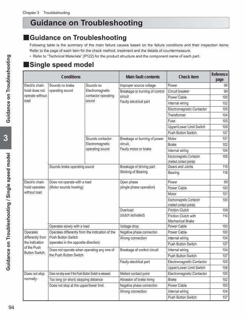
94
Chapter 3 Troubleshooting
3
Guidance on Troubleshooting
Conditions Main fault contents Check item Reference page
Electric chain hoist does not operate without load
Sounds no brake operating sound
Sounds no Electromagnetic contactor operating sound
Improper source voltage Power 99Breakage or burning of control circuitFaulty electrical part
Circuit breaker 99Power Cable 100Internal wiring 102Electromagnetic Contactor 105Transformer 104Fuse 105Upper/Lower Limit Switch 106Push Button Switch 107
Sounds contactor Electromagnetic operating sound
Breakage or burning of power circuit,Faulty motor or brake
Motor 101Brake 102Internal wiring 104Electromagnetic Contactor (melted contact points)
105
Sounds brake operating sound Breakage of driving partSticking of Bearing
Gears and Joints 115Bearing 116
Electric chain hoist operates without load
Does not operate with a load (Motor sounds howling)
Open phase (single phase operation)
Power 99Power Cable 100Motor 101Electromagnetic Contactor (melted contact points)
105
Overload (clutch activated)
Friction Clutch 109Friction Clutch with Mechanical Brake
110
Operates slowly with a load Voltage drop Power Cable 100Operates differently from the indication of the Push Button Switch.
Operates differently from the indication of the Push Button Switch (operates in the opposite direction)
Negative phase connection Power Cable 100Wrong connection Internal wiring 104
Push Button Switch 107Does not operate when operating any one of the Push Button Switch
Breakage of control circuit Internal wiring 104Push Button Switch 107
Faulty electrical part Electromagnetic Contactor 105Upper/Lower Limit Switch 106
Does not stop normally.
Does not stop even if the Push Button Switch is released. Melted contact point Electromagnetic Contactor 105Too long (or short) stopping distance Abrasion of brake lining Brake 102Does not stop at the upper/lower limit. Negative phase connection Power Cable 100
Wrong connection Internal wiring 104Push Button Switch 107
Single speed model ■
Guidance on Troubleshooting ■Following table is the summary of the main failure causes based on the failure conditions and their inspection items. Refer to the page of each item for the check method, treatment and the details of countermeasure.
Refer to “Technical Materials” (P122) for the product structure and the component name of each part.•
Gui
danc
e on
Tro
uble
shoo
ting
/ Sin
gle
spee
d m
odel
Gui
danc
e on
Tro
uble
shoo
ting
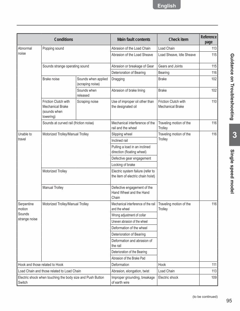
95
3
Conditions Main fault contents Check item Reference page
Abnormal noise
Popping sound Abrasion of the Load Chain Load Chain 113Abrasion of the Load Sheave Load Sheave, Idle Sheave 115
Sounds strange operating sound Abrasion or breakage of Gear Gears and Joints 115Deterioration of Bearing Bearing 116
Brake noise Sounds when applied (scraping noise)
Dragging Brake 102
Sounds when released
Abrasion of brake lining Brake 102
Friction Clutch with Mechanical Brake (sounds when lowering)
Scraping noise Use of improper oil other than the designated oil
Friction Clutch with Mechanical Brake
110
Sounds at curved rail (friction noise) Mechanical interference of the rail and the wheel
Traveling motion of the Trolley
116
Unable to travel
Motorized Trolley/Manual Trolley Slipping wheel Traveling motion of the Trolley
116Inclined railPulling a load in an inclined direction (floating wheel)Defective gear engagementLocking of brake
Motorized Trolley Electric system failure (refer to the item of electric chain hoist)
Manual Trolley Defective engagement of the Hand Wheel and the Hand Chain
Serpentine motionSounds strange noise
Motorized Trolley/Manual Trolley Mechanical interference of the rail and the wheel
Traveling motion of the Trolley
116
Wrong adjustment of collarUneven abrasion of the wheelDeformation of the wheelDeterioration of BearingDeformation and abrasion of the railDeterioration of the BearingAbrasion of the Brake Pad
Hook and those related to Hook Deformation Hook 111Load Chain and those related to Load Chain Abrasion, elongation, twist Load Chain 113Electric shock when touching the body size and Push Button Switch
Improper grounding, breakage of earth wire
Electric shock 109
Guidance on Troubleshooting
Single speed model
(to be continued)

96
Chapter 3 Troubleshooting
3
Conditions Main fault contents Check item Reference page
Unable to restart the VFD by resetting with emergency stop (the case when the VFD cannot be reset even after cool down)
Those related to VFD Check the error code of VFD referring to “VFD Manual”.
“VFD Manual” (annex)
Electric chain hoist does not operate without load
Sounds no brake operating sound Improper source voltage Power 99Breakage and burning of control circuitFaulty electrical part
Circuit breaker 99Power Cable 100Internal wiring 104Transformer 104Fuse 105Relay 105Interface Board 108VFD 108Upper/Lower Limit Switch 106Push Button Switch 107
Breakage and burning of power circuitFailure of motor or brake
Motor 101Brake 102Internal wiring 104Relay (melted contact point) 105
VFD trip due to motor overheat (electronic thermal relay)
VFD 108
VFD overheat VFD 108Sounds brake operating sound Breakage of driving part
Sticking of BearingGears and Joints 115Bearing 116
Electric chain hoist operates without load
Does not operate with a load (Motor sounds howling)
Overload (Clutch activated)
Friction Clutch 109Friction Clutch with Mechanical Brake
110
Operates slowly with a load Voltage drop Power Cable 100Electric chain hoist operates in low speed mode, but does not operate in high speed mode or operates slowly.
Low source voltage Power 99Voltage drop Power Cable 100
Does not operate in lowering or in low speed mode. Faulty Braking Resistor Braking Resistor 108Operates differently from the indication of the Push Button Switch.
Operates differently from the indication of the Push Button Switch (operates in the opposite direction)
Negative phase connection of motor lead wires
Motor 100
Wrong connection Internal wiring 104Push Button Switch 107
Does not operate when operating any one of the Push Button Switch
Breakage of control circuit Internal wiring 104Push Button Switch 107
Faulty electrical part VFD 108Interface Board 108Upper/Lower Limit Switch 106
Guidance on Troubleshooting (continued)
Dual Speed VFD Model ■
Dua
l Spe
ed V
FD M
odel
Gui
danc
e on
Tro
uble
shoo
ting
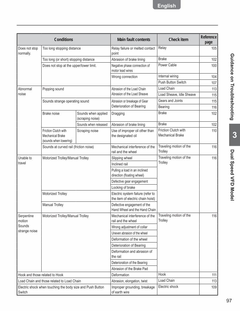
97
3
Conditions Main fault contents Check item Reference page
Does not stop normally.
Too long stopping distance Relay failure or melted contact point
Relay 105
Too long (or short) stopping distance Abrasion of brake lining Brake 102Does not stop at the upper/lower limit. Negative phase connection of
motor lead wiresPower Cable 100
Wrong connection Internal wiring 104Push Button Switch 107
Abnormal noise
Popping sound Abrasion of the Load ChainAbrasion of the Load Sheave
Load Chain 113Load Sheave, Idle Sheave 115
Sounds strange operating sound Abrasion or breakage of GearDeterioration of Bearing
Gears and Joints 115Bearing 116
Brake noise Sounds when applied (scraping noise)
Dragging Brake 102
Sounds when released Abrasion of brake lining Brake 102Friction Clutch with Mechanical Brake (sounds when lowering)
Scraping noise Use of improper oil other than the designated oil
Friction Clutch with Mechanical Brake
110
Sounds at curved rail (friction noise) Mechanical interference of the rail and the wheel
Traveling motion of the Trolley
116
Unable to travel
Motorized Trolley/Manual Trolley Slipping wheel Traveling motion of the Trolley
116Inclined railPulling a load in an inclined direction (floating wheel)Defective gear engagementLocking of brake
Motorized Trolley Electric system failure (refer to the item of electric chain hoist)
Manual Trolley Defective engagement of the Hand Wheel and the Hand Chain
Serpentine motionSounds strange noise
Motorized Trolley/Manual Trolley Mechanical interference of the rail and the wheel
Traveling motion of the Trolley
116
Wrong adjustment of collarUneven abrasion of the wheelDeformation of the wheelDeterioration of BearingDeformation and abrasion of the railDeterioration of the BearingAbrasion of the Brake Pad
Hook and those related to Hook Deformation Hook 111Load Chain and those related to Load Chain Abrasion, elongation, twist Load Chain 113Electric shock when touching the body size and Push Button Switch
Improper grounding, breakage of earth wire
Electric shock 109
Guidance on Troubleshooting
Dual Speed VFD
Model
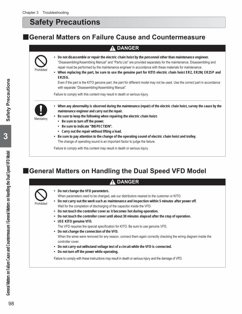
98
Chapter 3 Troubleshooting
3
Safety Precautions
Do not disassemble or repair the electric chain hoist by the personnel other than maintenance engineer. •“Disassembling/Assembling Manual” and “Parts List” are provided separately for the maintenance. Disassembling and repair must be performed by the maintenance engineer in accordance with these materials for maintenance.When replacing the part, be sure to use the genuine part for KITO electric chain hoist ER2, ER2M, ER2SP and •ER2SG.Even if the part is the KITO genuine part, the part for different model may not be used. Use the correct part in accordance with separate “Disassembling/Assembling Manual”.
Failure to comply with this content may result in death or serious injury.
Prohibited
Mandatory
When any abnormality is observed during the maintenance (repair) of the electric chain hoist, survey the cause by the •maintenance engineer and carry out the repair.Be sure to keep the following when repairing the electric chain hoist: •
Be sure to turn off the power. •Be sure to indicate “INSPECTION”. •Carry out the repair without lifting a load. •
Be sure to pay attention to the change of the operating sound of electric chain hoist and trolley. •The change of operating sound is an important factor to judge the failure.
Failure to comply with this content may result in death or serious injury.
General Matters on Failure Cause and Countermeasure ■
General Matters on Handling the Dual Speed VFD Model ■
Do not change the VFD parameters. •When parameters need to be changed, ask our distributors nearest to the customer or KITO.Do not carry out the work such as maintenance and inspection within 5 minutes after power off. •Wait for the completion of discharging of the capacitor inside the VFD.Do not touch the controller cover as it becomes hot during operation. •Do not touch the controller cover until about 30 minutes elapsed after the stop of operation. •USE KITO genuine VFD. •The VFD requires the special specification for KITO. Be sure to use genuine VFD.Do not change the connection of the VFD. •When the wires were removed for any reason, connect them again correctly checking the wiring diagram inside the controller cover.Do not carry out withstand voltage test of a circuit while the VFD is connected. •Do not turn off the power while operating. •
Failure to comply with these instructions may result in death or serious injury and the damage of VFD.
Prohibited
Gener
al Matte
rs on F
ailure C
ause a
nd Co
unterm
easure
/ Gene
ral Ma
tters o
n Hand
ling the
Dual S
peed V
FD Mo
delSa
fety
Pre
caut
ions
DANGER
DANGER

99
3
Power
Symptom Cause Remedy Main factor CountermeasureElectric chain hoist does not operate.
Improper source voltage
Measure the voltage of each phase at power receiving terminal.If the source voltage is improper, check the power receiving facility.
Faulty power receiving facility
Check the power receiving facility regularly.
Circuit breaker (Distribution panel)
Symptom Cause Remedy Main factor CountermeasureElectric chain hoist does not operate.
Breaker was tripped due to short circuit.
Replace or repair the short-circuited part. Cable breakage, burning of electrical parts
Refer to each item of Power Cable, Motor, Brake, Internal Wiring, Transformer and Electromagnetic Contactor.
Breaker was tripped due to insufficient breaker capacity.
Check the breaker capacity. Replace it if the capacity is insufficient.
Wrong selection of breaker capacity
Use the breaker with proper capacity. (See P54.)
Breaker was tripped due to over current.
Check the cause of over current and take the necessary countermeasure. (Refer to each item of Power Cable, Motor, Brake, Internal Wiring, Transformer and Contactor.)
Over voltage, low voltage, over load
Refer to each item of Power Cable, Motor, Brake, Internal Wiring, Transformer and Electromagnetic Contactor.
Troubleshooting
Be careful about electric shock when •checking the power.
Careless power check may result in death or serious injury due to electric shock.
TroubleshootingPow
er / Circuit breaker (D
istribution panel)
(to be continued)
Mandatory
DANGER

100
Chapter 3 Troubleshooting
3
Troubleshooting (continued)
Power Cable
Symptom Cause Remedy Main factor CountermeasureElectric chain hoist does not operate.
Wire breakage (more than two wires)
Check the conduction, flaw, crimping of terminals and soldering of plug.When any deficiency was observed, repair or replace the cable.
Excessive force applied on the cable
Support the cable with Cable Support Arm securely.
Non use of shake proof cable
Use shake proof cable to the moving part.
Twist of wire Layout the wires without twisting.
Cable was impeded by other facility.
Fix the cable not to be impeded by other facility.
Wire burning (more than two wires)
Check the cable. Replace it if burnt. Temperature rise due to insufficient cable capacity
Use the cable with proper capacity. (See P54.)
Cables are bundled. Do not bundle wires.
Insufficient insertion of plug
Insert the connector plug to the end of the receptacle. Tighten the coupling ring securely.
Insufficient insertion at the installation
Fix the connector plug to the receptacle securely.
Loosening of the fixing thread due to impact or vibration
Use the electric chain hoist avoiding the large impact.
Slow start or unable to start
Insufficient cable capacity
Check the cable size for adequacy. Replace with the proper cable if the cable capacity is insufficient.
Voltage drop due to insufficient cable capacity
Use the cable with proper capacity. (See P54.)
Electric chain hoist operates but unable to lift a load. (single phase status)
Breakage or burning of one phase only Refer to the breakage and burning of above items.
For single speed model, the electric chain hoist operates in the direction different to the push button operation (negative phase).* For dual speed
VFD model, refer to the item of VFD.
Wrong connection of power line when wiring
Change two wires of power line. Wrong connection when assembling
Refer to the connection diagram and connect wires correctly.
Do not change the connection at the Push •Button Switch circuit.
The change of circuit at the Push Button Switch circuit is very dangerous as the limit switch becomes not to function.
Prohibited
Pow
er C
able
Trou
bles
hoot
ing
DANGER
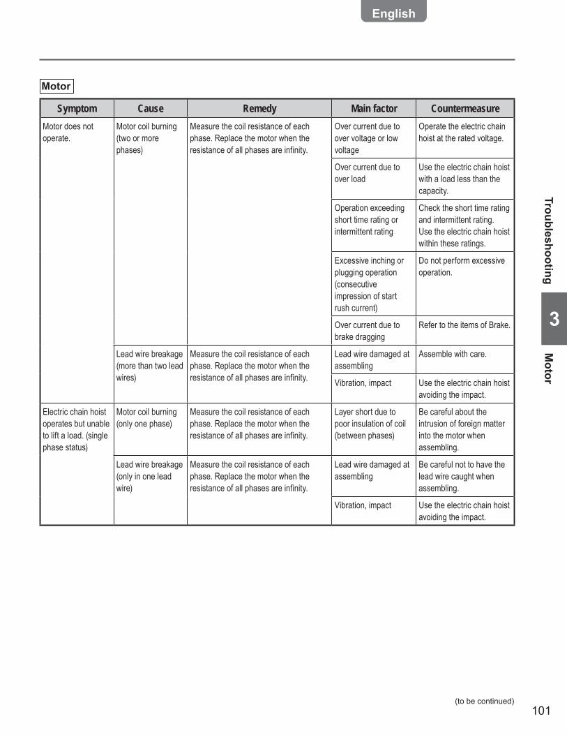
101
3
Motor
Symptom Cause Remedy Main factor CountermeasureMotor does not operate.
Motor coil burning (two or more phases)
Measure the coil resistance of each phase. Replace the motor when the resistance of all phases are infinity.
Over current due to over voltage or low voltage
Operate the electric chain hoist at the rated voltage.
Over current due to over load
Use the electric chain hoist with a load less than the capacity.
Operation exceeding short time rating or intermittent rating
Check the short time rating and intermittent rating. Use the electric chain hoist within these ratings.
Excessive inching or plugging operation (consecutive impression of start rush current)
Do not perform excessive operation.
Over current due to brake dragging
Refer to the items of Brake.
Lead wire breakage (more than two lead wires)
Measure the coil resistance of each phase. Replace the motor when the resistance of all phases are infinity.
Lead wire damaged at assembling
Assemble with care.
Vibration, impact Use the electric chain hoist avoiding the impact.
Electric chain hoist operates but unable to lift a load. (single phase status)
Motor coil burning (only one phase)
Measure the coil resistance of each phase. Replace the motor when the resistance of all phases are infinity.
Layer short due to poor insulation of coil (between phases)
Be careful about the intrusion of foreign matter into the motor when assembling.
Lead wire breakage (only in one lead wire)
Measure the coil resistance of each phase. Replace the motor when the resistance of all phases are infinity.
Lead wire damaged at assembling
Be careful not to have the lead wire caught when assembling.
Vibration, impact Use the electric chain hoist avoiding the impact.
TroubleshootingM
otor
(to be continued)
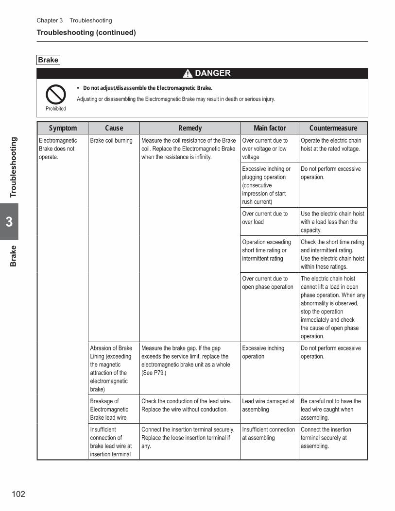
102
Chapter 3 Troubleshooting
3
Troubleshooting (continued)
Brake
Do not adjust/disassemble the Electromagnetic Brake. •
Adjusting or disassembling the Electromagnetic Brake may result in death or serious injury.Prohibited
DANGER
Symptom Cause Remedy Main factor CountermeasureElectromagnetic Brake does not operate.
Brake coil burning Measure the coil resistance of the Brake coil. Replace the Electromagnetic Brake when the resistance is infinity.
Over current due to over voltage or low voltage
Operate the electric chain hoist at the rated voltage.
Excessive inching or plugging operation (consecutive impression of start rush current)
Do not perform excessive operation.
Over current due to over load
Use the electric chain hoist with a load less than the capacity.
Operation exceeding short time rating or intermittent rating
Check the short time rating and intermittent rating. Use the electric chain hoist within these ratings.
Over current due to open phase operation
The electric chain hoist cannot lift a load in open phase operation. When any abnormality is observed, stop the operation immediately and check the cause of open phase operation.
Abrasion of Brake Lining (exceeding the magnetic attraction of the electromagnetic brake)
Measure the brake gap. If the gap exceeds the service limit, replace the electromagnetic brake unit as a whole (See P79.)
Excessive inching operation
Do not perform excessive operation.
Breakage of Electromagnetic Brake lead wire
Check the conduction of the lead wire. Replace the wire without conduction.
Lead wire damaged at assembling
Be careful not to have the lead wire caught when assembling.
Insufficient connection of brake lead wire at insertion terminal
Connect the insertion terminal securely.Replace the loose insertion terminal if any.
Insufficient connection at assembling
Connect the insertion terminal securely at assembling.
Bra
keTr
oubl
esho
otin
g

103
3
Symptom Cause Remedy Main factor CountermeasureElectromagnetic Brake does not operate.
Rusting When the Brake is rusted shut, replace the brake unit as a whole.
Wrong assembling of packings
Assemble the brake cover packings and V ring securely.Replace the packing if deteriorated.
Leaving the electric chain hoist in an environment with rich moisture
Operate the electric chain hoist regularly.
Dew condensation Pay attention to the use in an environment where the ambient temperature changes rapidly.
Breakage of rectifier Measure the resistance of the rectifier with circuit tester.Anode terminal : Negative probe of the
circuit testerCathode terminal : Positive probe of the
circuit tester (measure the resistance in kΩ range)
When the resistance is almost zero, the rectifier is normal.In other cases, replace the rectifier.
Over current due to over voltage or low voltage
Operate the electric chain hoist at the rated voltage.
Excessive inching or plugging operation (consecutive impression of start rush current)
Do not perform excessive operation.
Over current due to over load
Use the electric chain hoist with a load less than the capacity.
Operation exceeding short time rating or intermittent rating
Check the short time rating and intermittent rating. Use the electric chain hoist within these ratings.
Over current due to open phase operation
The electric chain hoist cannot lift a load in open phase operation. When any abnormality is observed, stop the operation immediately and check the cause of open phase operation.
Too long (or short) stopping distance (stopping distance may change slightly depending on the temperature.)
Abrasion of brake lining
Measure the brake gap. If the gap exceeds the service limit, replace the electromagnetic brake unit as a whole (See P79.)
Excessive inching operation
Do not perform excessive operation.
Louder operating sounds
Abrasion of brake lining
Measure the brake gap. If the gap exceeds the service limit, replace the electromagnetic brake unit as a whole (See P79.)
Excessive inching operation
Do not perform excessive operation.
TroubleshootingB
rake
(to be continued)
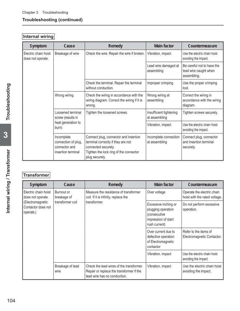
104
Chapter 3 Troubleshooting
3
Troubleshooting (continued)
Internal wiring
Symptom Cause Remedy Main factor CountermeasureElectric chain hoist does not operate.
Breakage of wire Check the wire. Repair the wire if broken. Vibration, impact Use the electric chain hoist avoiding the impact.
Lead wire damaged at assembling
Be careful not to have the lead wire caught when assembling.
Check the terminal. Repair the terminal without conduction.
Improper crimping Use the proper crimping tool.
Wrong wiring Check the wiring in accordance with the wiring diagram. Correct the wiring if it is wrong.
Wrong wiring at assembling
Correct the wiring in accordance with the wiring diagram.
Loosened terminal screw (results in heat generation to burn)
Tighten the loosened screws. Insufficient tightening at assembling
Tighten screws securely.
Vibration, impact Use the electric chain hoist avoiding the impact.
Incomplete connection of plug, connector and insertion terminal
Connect plug, connector and insertion terminal correctly if they are not connected securely.Tighten the lock ring of the connector plug securely.
Incomplete connection at assembling
Connect plug, connector and insertion terminal securely.
Transformer
Symptom Cause Remedy Main factor CountermeasureElectric chain hoist does not operate. (Electromagnetic Contactor does not operate.)
Burnout or breakage of transformer coil
Measure the resistance of transformer coil. If it is infinity, replace the transformer.
Over voltage Operate the electric chain hoist with the rated voltage.
Excessive inching or plugging operation (consecutive impression of start rush current)
Do not perform excessive operation.
Over current due to defective operation of Electromagnetic contactor
Refer to the items of Electromagnetic Contactor.
Vibration, impact Use the electric chain hoist avoiding the impact.
Breakage of lead wire
Check the lead wires of the transformer. Repair or replace the transformer if the lead wire has no conduction.
Vibration, impact Use the electric chain hoist avoiding the impact.
Inte
rnal
wiri
ng /
Tran
sfor
mer
Trou
bles
hoot
ing
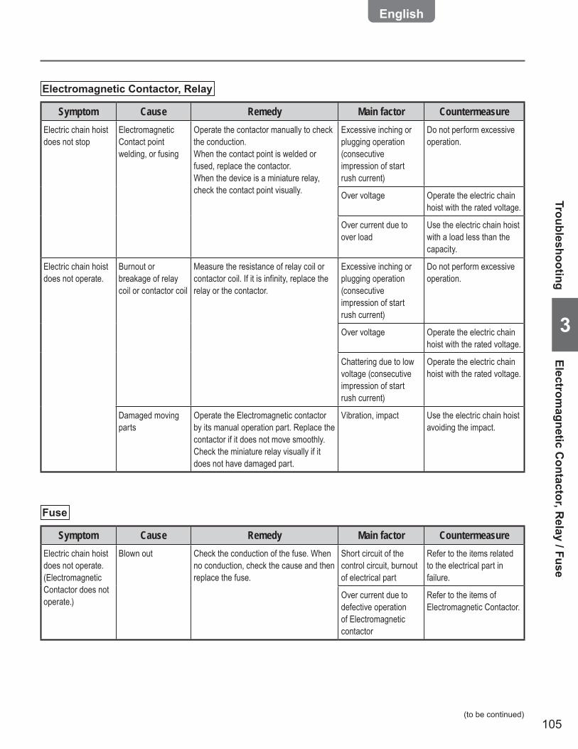
105
3
Electromagnetic Contactor, Relay
Symptom Cause Remedy Main factor CountermeasureElectric chain hoist does not stop
Electromagnetic Contact point welding, or fusing
Operate the contactor manually to check the conduction.When the contact point is welded or fused, replace the contactor.When the device is a miniature relay, check the contact point visually.
Excessive inching or plugging operation (consecutive impression of start rush current)
Do not perform excessive operation.
Over voltage Operate the electric chain hoist with the rated voltage.
Over current due to over load
Use the electric chain hoist with a load less than the capacity.
Electric chain hoist does not operate.
Burnout or breakage of relay coil or contactor coil
Measure the resistance of relay coil or contactor coil. If it is infinity, replace the relay or the contactor.
Excessive inching or plugging operation (consecutive impression of start rush current)
Do not perform excessive operation.
Over voltage Operate the electric chain hoist with the rated voltage.
Chattering due to low voltage (consecutive impression of start rush current)
Operate the electric chain hoist with the rated voltage.
Damaged moving parts
Operate the Electromagnetic contactor by its manual operation part. Replace the contactor if it does not move smoothly.Check the miniature relay visually if it does not have damaged part.
Vibration, impact Use the electric chain hoist avoiding the impact.
Fuse
Symptom Cause Remedy Main factor CountermeasureElectric chain hoist does not operate. (Electromagnetic Contactor does not operate.)
Blown out Check the conduction of the fuse. When no conduction, check the cause and then replace the fuse.
Short circuit of the control circuit, burnout of electrical part
Refer to the items related to the electrical part in failure.
Over current due to defective operation of Electromagnetic contactor
Refer to the items of Electromagnetic Contactor.
TroubleshootingElectrom
agnetic Contactor, R
elay / Fuse
(to be continued)
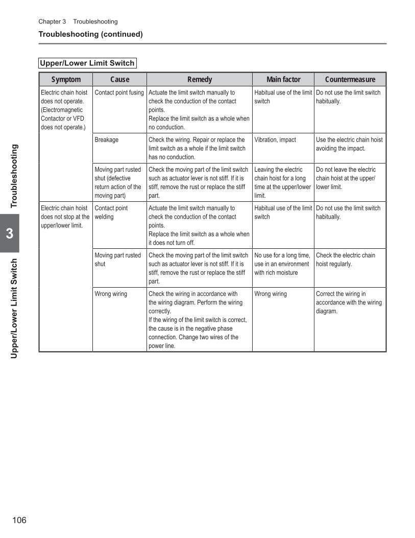
106
Chapter 3 Troubleshooting
3
Troubleshooting (continued)
Upper/Lower Limit Switch
Symptom Cause Remedy Main factor CountermeasureElectric chain hoist does not operate. (Electromagnetic Contactor or VFD does not operate.)
Contact point fusing Actuate the limit switch manually to check the conduction of the contact points.Replace the limit switch as a whole when no conduction.
Habitual use of the limit switch
Do not use the limit switch habitually.
Breakage Check the wiring. Repair or replace the limit switch as a whole if the limit switch has no conduction.
Vibration, impact Use the electric chain hoist avoiding the impact.
Moving part rusted shut (defective return action of the moving part)
Check the moving part of the limit switch such as actuator lever is not stiff. If it is stiff, remove the rust or replace the stiff part.
Leaving the electric chain hoist for a long time at the upper/lower limit.
Do not leave the electric chain hoist at the upper/lower limit.
Electric chain hoist does not stop at the upper/lower limit.
Contact point welding
Actuate the limit switch manually to check the conduction of the contact points.Replace the limit switch as a whole when it does not turn off.
Habitual use of the limit switch
Do not use the limit switch habitually.
Moving part rusted shut
Check the moving part of the limit switch such as actuator lever is not stiff. If it is stiff, remove the rust or replace the stiff part.
No use for a long time, use in an environment with rich moisture
Check the electric chain hoist regularly.
Wrong wiring Check the wiring in accordance with the wiring diagram. Perform the wiring correctly.If the wiring of the limit switch is correct, the cause is in the negative phase connection. Change two wires of the power line.
Wrong wiring Correct the wiring in accordance with the wiring diagram.
Upp
er/L
ower
Lim
it Sw
itch
Trou
bles
hoot
ing
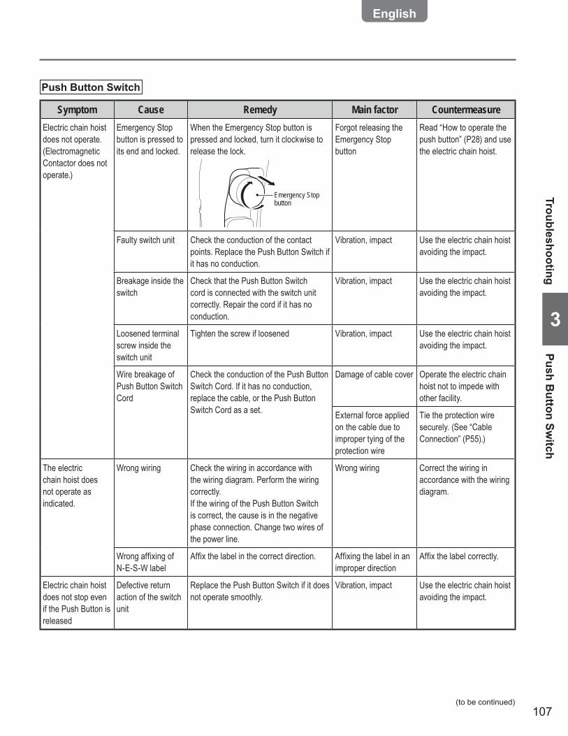
107
3
Push Button Switch
Symptom Cause Remedy Main factor CountermeasureElectric chain hoist does not operate. (Electromagnetic Contactor does not operate.)
Emergency Stop button is pressed to its end and locked.
When the Emergency Stop button is pressed and locked, turn it clockwise to release the lock.
Emergency Stop button
Forgot releasing the Emergency Stop button
Read “How to operate the push button” (P28) and use the electric chain hoist.
Faulty switch unit Check the conduction of the contact points. Replace the Push Button Switch if it has no conduction.
Vibration, impact Use the electric chain hoist avoiding the impact.
Breakage inside the switch
Check that the Push Button Switch cord is connected with the switch unit correctly. Repair the cord if it has no conduction.
Vibration, impact Use the electric chain hoist avoiding the impact.
Loosened terminal screw inside the switch unit
Tighten the screw if loosened Vibration, impact Use the electric chain hoist avoiding the impact.
Wire breakage of Push Button Switch Cord
Check the conduction of the Push Button Switch Cord. If it has no conduction, replace the cable, or the Push Button Switch Cord as a set.
Damage of cable cover Operate the electric chain hoist not to impede with other facility.
External force applied on the cable due to improper tying of the protection wire
Tie the protection wire securely. (See “Cable Connection” (P55).)
The electric chain hoist does not operate as indicated.
Wrong wiring Check the wiring in accordance with the wiring diagram. Perform the wiring correctly.If the wiring of the Push Button Switch is correct, the cause is in the negative phase connection. Change two wires of the power line.
Wrong wiring Correct the wiring in accordance with the wiring diagram.
Wrong affixing of N-E-S-W label
Affix the label in the correct direction. Affixing the label in an improper direction
Affix the label correctly.
Electric chain hoist does not stop even if the Push Button is released
Defective return action of the switch unit
Replace the Push Button Switch if it does not operate smoothly.
Vibration, impact Use the electric chain hoist avoiding the impact.
TroubleshootingPush B
utton Switch
(to be continued)

108
Chapter 3 Troubleshooting
3
Troubleshooting (continued)
VFD
Symptom Cause Remedy Main factor CountermeasureElectric chain hoist does not operate.
VFD failure Reset the VFD by pressing Emergency Stop button. It the VFD still does not operate, check it.
VFD failure Check the error code indicated by VFD referring to the “VFD Manual”.
Motor overheat Stop by motor thermal relay function of the VFDMotor resumes operation when the VFD is reset by pressing the Emergency Stop after cool down.
Operation exceeding short time rating or intermittent rating
Check the short time rating and intermittent rating. Use the electric chain hoist within these ratings.
VFD overheat Stop by overheat preventive function of the VFDMotor resumes operation when the VFD is reset by pressing the Emergency Stop after cool down.
Operation exceeding short time rating or intermittent rating
Check the short time rating and intermittent rating. Use the electric chain hoist within these ratings.
Expired service life of the VFD (capacitor)
Refer to the “VFD Manual”. Operation exceeding short time rating or intermittent rating
Check the short time rating and intermittent rating. Use the electric chain hoist within these ratings.
Interface Board
Symptom Cause Remedy Main factor CountermeasureElectric chain hoist does not operate.
Damaged circuit component
Press the Push Button to check whether LED on the board lights or not. If LED does not light, replace the board. ✽ This test is carried out with energizing the VFD. Be careful about electric shock.
Over current, over voltage, service life expiry
Operate the electric chain hoist at the rated voltage.Replace the Interface Board.
Contact failure of connector
Check the conduction of the connector. Replace the connector if it has no conduction.
Defective assembling of the connector
Crimp and insert the connector pins securely.
Braking Resistor
Symptom Cause Remedy Main factor CountermeasureElectric chain hoist does not operate.
Resistor breakage Measure the resistance of the resistor. Replace the resistor if the resistance is infinity.
Operation exceeding short time rating or intermittent rating, over load
Use the electric chain hoist within the ratings.
VFD
/ In
terf
ace
Boa
rd /
Bra
king
Res
isto
rTr
oubl
esho
otin
g
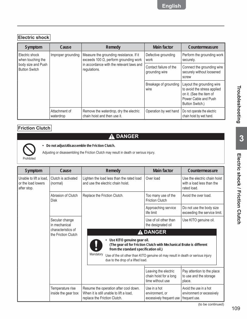
109
3Friction Clutch
Do not adjust/disassemble the Friction Clutch. •
Adjusting or disassembling the Friction Clutch may result in death or serious injury.Prohibited
DANGER
Symptom Cause Remedy Main factor CountermeasureUnable to lift a load, or the load lowers after stop.
Clutch is activated (normal)
Lighten the load less than the rated load and use the electric chain hoist.
Over load Use the electric chain hoist with a load less than the rated load.
Abrasion of Clutch Disk
Replace the Friction Clutch. Too many use of the Friction Clutch
Avoid the over load.
Approaching service life limit
Do not use the body size exceeding the service limit.
Secular change in mechanical characteristics of the Friction Clutch
Use of oil other than the designated oil
Use KITO genuine oil.
Leaving the electric chain hoist for a long time without use
Pay attention to the place to use and the storage place.
Temperature rise inside the gear box
Resume the operation after cool down.When it is still unable to lift a load, replace the Friction Clutch.
Use in a hot environment, or excessively frequent use
Avoid the use in a hot environment or excessively frequent use.
Use KITO genuine gear oil. •(The gear oil for Friction Clutch with Mechanical Brake is different from the standard specification oil.)
Use of the oil other than KITO genuine oil may result in death or serious injury due to the drop of a lifted load.
DANGER
Mandatory
Electric shock
Symptom Cause Remedy Main factor CountermeasureElectric shock when touching the body size and Push Button Switch
Improper grounding Measure the grounding resistance. If it exceeds 100 Ω, perform grounding work in accordance with the relevant laws and regulations.
Defective grounding work
Perform the grounding work securely.
Contact failure of the grounding wire
Connect the grounding wire securely without loosened screw
Breakage of grounding wire
Layout the grounding wire to avoid the stress applied on it. (See the item of Power Cable and Push Button Switch.)
Attachment of waterdrop
Remove the waterdrop, dry the electric chain hoist and then use it.
Operation by wet hand Do not operate the electric chain hoist by wet hand.
TroubleshootingElectric shock / Friction C
lutch
(to be continued)

110
Chapter 3 Troubleshooting
3
Friction Clutch with Mechanical Brake
Do not adjust/disassemble the Friction Clutch with Mechanical Brake. •
Adjusting or disassembling the Friction Clutch with Mechanical Brake may result in death or serious injury.Prohibited
DANGER
Symptom Cause Remedy Main factor CountermeasureUnable to lift a load. Clutch is activated
(normal)Lighten the load less than the rated load and use the electric chain hoist.
Over load Use the electric chain hoist with a load less than the rated load.
Abrasion of Clutch Disk
Replace the Friction Clutch with Mechanical Brake.
Too many use of the Friction Clutch
Avoid the over load.
Use of oil other than the designated oil
Use KITO genuine oil.
Secular change in mechanical characteristics of the Friction Clutch with Mechanical Brake
Leaving the electric chain hoist for a long time without use
Do not use the body size exceeding the service limit.
Temperature rise inside the gear box
Resume the operation after cool down.When it is still unable to lift a load, replace the Friction Clutch with Mechanical Brake.
Use in a hot environment, or excessively frequent use
Avoid the use in a hot environment or excessively frequent use.
Unable to lift a load, or the load lowers after stop.
Deteriorated braking performance
Replace the Friction Clutch with Mechanical Brake.
Use of oil other than the designated oil
Use KITO genuine oil.
Abrasion of the Brake Pad
Approaching service life limit
Do not use the body size exceeding the service limit.
Electric chain hoist of VFD specification became tripped frequently at lowering a load.
Abrasion of the Brake Pad
When the electric chain hoist trips frequently, replace the Friction Brake with Mechanical Brake with a new one.
Approaching service life limit
Check the Mechanical Brake if the tripping time increased. (See P81)
Troubleshooting (continued)
Use KITO genuine gear oil. (The •gear oil for Friction Clutch with Mechanical Brake is different from the standard specification oil.)
Use of the oil other than KITO genuine oil may result in death or serious injury due to the drop of a lifted load.
DANGER
Mandatory
Fric
tion
Clu
tch
with
Mec
hani
cal B
rake
Trou
bles
hoot
ing

111
3
Hook
Symptom Cause Remedy Main factor CountermeasureWidened Hook opening
Deformation of the Hook
Replace the Hook if the deformation exceeds the criteria. (See P70.)
Over load Use the electric chain hoist with a load less than the capacity.
Earth lifting Do not carry out earth lifting.Be careful not to impede the Hook with protruding object during lifting.
Slinging a load at the tip of the Hook.
Lateral pulling of the Hook
Sling a load at the center of the Hook
Improper slinging Angle formed by two slings must be 120 degrees or less.
120 degrees or less
Use of the sling with a size improper to the Hook
Use the proper sling.
Twisted hanging of the Hook
Use of the Hook with the Load Chain wound on a load
Do not wind the Load Chain directly on a load.
Hook unable to swivel smoothly at the neck
Rusting shut or corrosion of Bearing
Swivel the Hook at the neck by hand. If it is difficult to swivel smoothly, overhaul or replace the Bearing.
Insufficient grease application, corrosion due to environment of use
Apply grease regularly.Use the sling to avoid the dipping of the Hook into chemicals.
Damaged Bearing Intrusion of dust Be careful about the intrusion of foreign matter into the neck.
TroubleshootingH
ook
(to be continued)
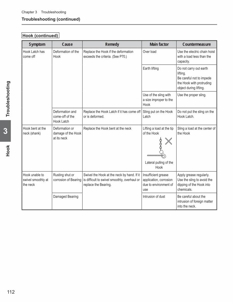
112
Chapter 3 Troubleshooting
3
Troubleshooting (continued)
Hook (continued)
Symptom Cause Remedy Main factor CountermeasureHook Latch has come off
Deformation of the Hook
Replace the Hook if the deformation exceeds the criteria. (See P70.)
Over load Use the electric chain hoist with a load less than the capacity.
Earth lifting Do not carry out earth lifting.Be careful not to impede the Hook with protruding object during lifting.
Use of the sling with a size improper to the Hook
Use the proper sling.
Deformation and come-off of the Hook Latch
Replace the Hook Latch if it has come off or is deformed.
Sling put on the Hook Latch
Do not put the sling on the Hook Latch.
Hook bent at the neck (shank)
Deformation or damage of the Hook at its neck
Replace the Hook bent at the neck Lifting a load at the tip of the Hook
Lateral pulling of the Hook
Sling a load at the center of the Hook
Hook unable to swivel smoothly at the neck
Rusting shut or corrosion of Bearing
Swivel the Hook at the neck by hand. If it is difficult to swivel smoothly, overhaul or replace the Bearing.
Insufficient grease application, corrosion due to environment of use
Apply grease regularly.Use the sling to avoid the dipping of the Hook into chemicals.
Damaged Bearing Intrusion of dust Be careful about the intrusion of foreign matter into the neck.
Hoo
kTr
oubl
esho
otin
g

113
3
Load Chain
Symptom Cause Remedy Main factor CountermeasureTwisted Load Chain Capsized Bottom
HookTurn over the Bottom Hook to the original position to cancel the capsizing.
Bottom Hook was turned over by one turn during working.
When using multi fall model hoist, check that the Hook is not capsized before use.
Load Chain is twisted inside the main body of the electric chain hoist.
Remove the Chain Guide A and the Load Chain, and then reassemble them.
Improper assembling Assemble the electric chain hoist correctly. (See Disassembling/Assembling Manual)
Sudden activation of the Friction Clutch when lowering
Knot of the Load Chain due to entanglement in the Chain Container
Check the capacity of the Chain Container (with the nameplate on the Chain Container). If insufficient, replace the Chain Container with a larger capacity.
Insufficient capacity of the Chain Container
When installing the electric chain hoist, check the lift and the capacity of the Chain Container, and assemble them correctly.
Sounds the popping sound
Abrasion of the Load Chain links
Measure the abrasion of wire diameter. Replace the Load Chain if it reaches at the abrasion limit. (See P69)
Long hour operation without grease
Apply lubricant regularly. (See P40)
Grease application portion
Load
Excessive inching operation
Do not perform excessive operation.
Over load Use the electric chain hoist with a load less than the capacity.
Pulling a load in an inclined direction
Do not pull a load in an inclined direction.
Abrasion of Load Sheave, Idle Sheave
Refer to the item of Load Sheave, Idle Sheave.
Elongation of pitch Measure the sum of pitches of 5 links. Replace the Load Chain if this value exceeds the limit value. (See P69)
Over load Use the electric chain hoist with a load less than the capacity.
TroubleshootingLoad C
hain
(to be continued)
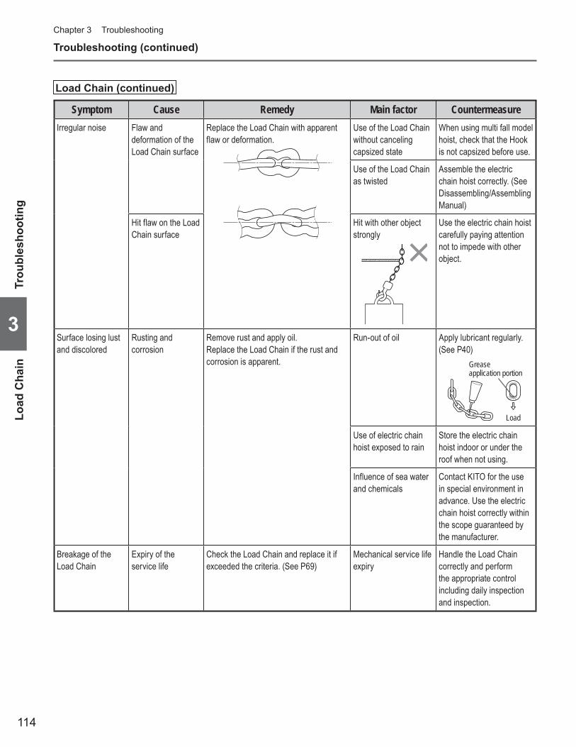
114
Chapter 3 Troubleshooting
3
Troubleshooting (continued)
Load Chain (continued)
Symptom Cause Remedy Main factor CountermeasureIrregular noise Flaw and
deformation of the Load Chain surface
Replace the Load Chain with apparent flaw or deformation.
Use of the Load Chain without canceling capsized state
When using multi fall model hoist, check that the Hook is not capsized before use.
Use of the Load Chain as twisted
Assemble the electric chain hoist correctly. (See Disassembling/Assembling Manual)
Hit flaw on the Load Chain surface
Hit with other object strongly
Use the electric chain hoist carefully paying attention not to impede with other object.
Surface losing lust and discolored
Rusting and corrosion
Remove rust and apply oil.Replace the Load Chain if the rust and corrosion is apparent.
Run-out of oil Apply lubricant regularly. (See P40)
Grease application portion
Load
Use of electric chain hoist exposed to rain
Store the electric chain hoist indoor or under the roof when not using.
Influence of sea water and chemicals
Contact KITO for the use in special environment in advance. Use the electric chain hoist correctly within the scope guaranteed by the manufacturer.
Breakage of the Load Chain
Expiry of the service life
Check the Load Chain and replace it if exceeded the criteria. (See P69)
Mechanical service life expiry
Handle the Load Chain correctly and perform the appropriate control including daily inspection and inspection.
Load
Cha
inTr
oubl
esho
otin
g
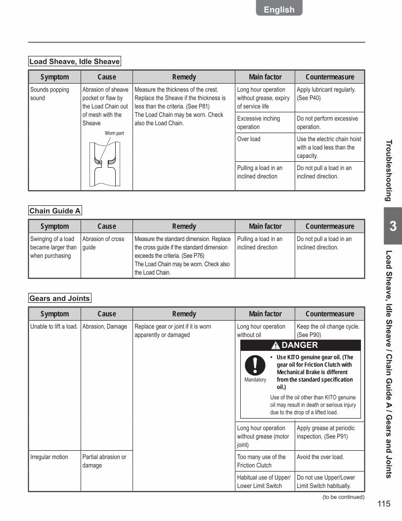
115
3
Load Sheave, Idle Sheave
Symptom Cause Remedy Main factor CountermeasureSounds popping sound
Abrasion of sheave pocket or flaw by the Load Chain out of mesh with the Sheave
Worn part
Measure the thickness of the crest. Replace the Sheave if the thickness is less than the criteria. (See P81)The Load Chain may be worn. Check also the Load Chain.
Long hour operation without grease, expiry of service life
Apply lubricant regularly. (See P40)
Excessive inching operation
Do not perform excessive operation.
Over load Use the electric chain hoist with a load less than the capacity.
Pulling a load in an inclined direction
Do not pull a load in an inclined direction.
Chain Guide A
Symptom Cause Remedy Main factor CountermeasureSwinging of a load became larger than when purchasing
Abrasion of cross guide
Measure the standard dimension. Replace the cross guide if the standard dimension exceeds the criteria. (See P76)The Load Chain may be worn. Check also the Load Chain.
Pulling a load in an inclined direction
Do not pull a load in an inclined direction.
Gears and Joints
Symptom Cause Remedy Main factor CountermeasureUnable to lift a load. Abrasion, Damage Replace gear or joint if it is worn
apparently or damagedLong hour operation without oil
Keep the oil change cycle. (See P90)
Long hour operation without grease (motor joint)
Apply grease at periodic inspection. (See P91)
Irregular motion Partial abrasion or damage
Too many use of the Friction Clutch
Avoid the over load.
Habitual use of Upper/Lower Limit Switch
Do not use Upper/Lower Limit Switch habitually.
TroubleshootingLoad Sheave, Idle Sheave / C
hain Guide A / G
ears and Joints
(to be continued)
DANGERUse KITO genuine gear oil. (The •gear oil for Friction Clutch with Mechanical Brake is different from the standard specification oil.)
Use of the oil other than KITO genuine oil may result in death or serious injury due to the drop of a lifted load.
Mandatory
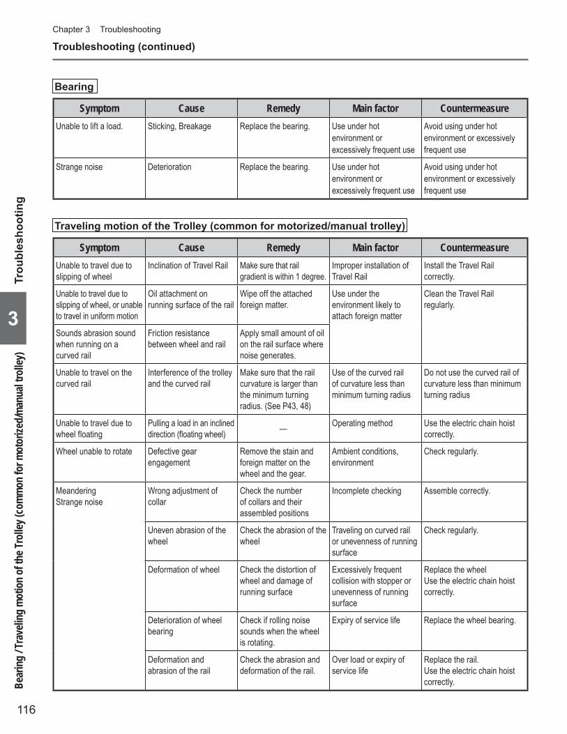
116
Chapter 3 Troubleshooting
3
Troubleshooting (continued)
Bearing
Symptom Cause Remedy Main factor CountermeasureUnable to lift a load. Sticking, Breakage Replace the bearing. Use under hot
environment or excessively frequent use
Avoid using under hot environment or excessively frequent use
Strange noise Deterioration Replace the bearing. Use under hot environment or excessively frequent use
Avoid using under hot environment or excessively frequent use
Traveling motion of the Trolley (common for motorized/manual trolley)
Symptom Cause Remedy Main factor CountermeasureUnable to travel due to slipping of wheel
Inclination of Travel Rail Make sure that rail gradient is within 1 degree.
Improper installation of Travel Rail
Install the Travel Rail correctly.
Unable to travel due to slipping of wheel, or unable to travel in uniform motion
Oil attachment on running surface of the rail
Wipe off the attached foreign matter.
Use under the environment likely to attach foreign matter
Clean the Travel Rail regularly.
Sounds abrasion sound when running on a curved rail
Friction resistance between wheel and rail
Apply small amount of oil on the rail surface where noise generates.
Unable to travel on the curved rail
Interference of the trolley and the curved rail
Make sure that the rail curvature is larger than the minimum turning radius. (See P43, 48)
Use of the curved rail of curvature less than minimum turning radius
Do not use the curved rail of curvature less than minimum turning radius
Unable to travel due to wheel floating
Pulling a load in an inclined direction (floating wheel) — Operating method Use the electric chain hoist
correctly.
Wheel unable to rotate Defective gear engagement
Remove the stain and foreign matter on the wheel and the gear.
Ambient conditions, environment
Check regularly.
MeanderingStrange noise
Wrong adjustment of collar
Check the number of collars and their assembled positions
Incomplete checking Assemble correctly.
Uneven abrasion of the wheel
Check the abrasion of the wheel
Traveling on curved rail or unevenness of running surface
Check regularly.
Deformation of wheel Check the distortion of wheel and damage of running surface
Excessively frequent collision with stopper or unevenness of running surface
Replace the wheelUse the electric chain hoist correctly.
Deterioration of wheel bearing
Check if rolling noise sounds when the wheel is rotating.
Expiry of service life Replace the wheel bearing.
Deformation and abrasion of the rail
Check the abrasion and deformation of the rail.
Over load or expiry of service life
Replace the rail.Use the electric chain hoist correctly.Be
aring
/ Tra
velin
g mot
ion of
the T
rolle
y (co
mmon
for m
otor
ized/m
anua
l troll
ey)
Trou
bles
hoot
ing

117
3
Traveling motion of the Trolley (only for motorized trolley)
Symptom Cause Remedy Main factor CountermeasureWheel unable to rotate Locking of brake Disassemble the motor
cover. Remove rust and stains.
Ambient conditions, environment
Check regularly.
Electric system failure (Refer to the items of Electric chain hoist)
(Refer to the items of Electric chain hoist)
Serpentine motionStrange noise
Abrasion of the side roller Check the abrasion Traveling on curved rail or expiry of service life
Check regularly.
Abrasion of the Brake Pad
Check the abrasion of the Brake Pad
Expiry of service life Check regularly.
Traveling motion of the Trolley (only for manual trolley)
Symptom Cause Remedy Main factor CountermeasureUnable to pull the Hand Chain
Defective engagement of the Hand Wheel and the Hand Chain
Engage the Hand Chain with the Hand Wheel correctly.
Rapid operation Replace the Hand Chain with abrasion or deformation.
TroubleshootingTraveling motion of the Trolley (only for motorized trolley) / Traveling motion of the Trolley (only for manual trolley)

118
Chapter 3 Troubleshooting

119
AppendixThis Appendix summarizes the information helpful for the use of KITO electric chain hoist, such as optional parts, technical materials and service network.
Optional Parts ■ ................................................................................120Product Structure and Names of Each Part ■ ...............................122Technical Material ■ .........................................................................124
Hook Dimensions (for ER2)• .......................................................124Table of Lifting Load• ...................................................................124Rated Motor Current• ...................................................................124Specifi cation and Dimensions of Single Speed ER2• .......................126Specifi cation and Dimensions of Single Speed ER2M• .....................127Specifi cation and Dimensions of Single Speed ER2SP• ...................128Specifi cation and Dimensions of Single Speed ER2SG• ...................129Specifi cation and Dimensions of Dual Speed VFD ER2• ...................130Specifi cation and Dimensions of Dual Speed• ER2 (500V class) ...... 132Specifi cation and Dimensions of Dual Speed VFD ER2M• ................134Specifi cation and Dimensions of Dual Speed ER2M • (500V class) ....136Conversion Table between Lift/Travel/Speed• ...........................138Clearance between Trolley and Applicable Rail• .......................139Wiring Diagram of Single Speed ER2/ER2SP/ER2SG• .............140Wiring Diagram of Dual Speed ER2/ER2SP/ER2SG• ................143Wiring Diagram of Single Speed ER2M• ....................................146Wiring Diagram of • Dual Speed ER2M .......................................149
Check Sheet for ER2 Series Electric Chain Hoist Daily inspection ■ ........152Check Sheet for ER2 Series Electric Chain Hoist Frequent Inspection ■ ........ 154Check Sheet for ER2 Series Electric Chain Hoist Periodic Inspection ■ ........156
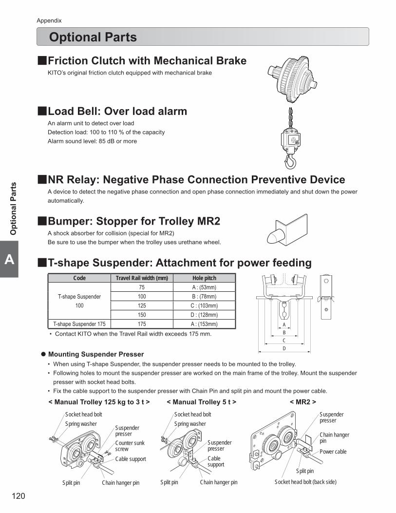
120
Appendix
A
Optional Parts
Friction Clutch with Mechanical Brake ■KITO’s original friction clutch equipped with mechanical brake
Load Bell: Over load alarm ■An alarm unit to detect over loadDetection load: 100 to 110 % of the capacityAlarm sound level: 85 dB or more
NR Relay: Negative Phase Connection Preventive Device ■A device to detect the negative phase connection and open phase connection immediately and shut down the power automatically.
Bumper: Stopper for Trolley MR2 ■A shock absorber for collision (special for MR2)Be sure to use the bumper when the trolley uses urethane wheel.
T-shape Suspender: Attachment for power feeding ■Code Travel Rail width (mm) Hole pitch
T-shape Suspender100
75 A : (53mm)100 B : (78mm)125 C : (103mm)150 D : (128mm)
T-shape Suspender 175 175 A : (153mm)Contact KITO when the Travel Rail width exceeds 175 mm.•
ABCD
< Manual Trolley 125 kg to 3 t > < Manual Trolley 5 t > < MR2 >
Mounting Suspender Presser ●
When using T-shape Suspender, the suspender presser needs to be mounted to the trolley.• Following holes to mount the suspender presser are worked on the main frame of the trolley. Mount the suspender • presser with socket head bolts.Fix the cable support to the suspender presser with Chain Pin and split pin and mount the power cable.•
Chain hanger pin
Power cable
Split pin
Socket head bolt (back side)
Suspender presser
Socket head boltSpring washer
Split pin Chain hanger pin
Cable support
Suspender presserCounter sunk screw
Socket head boltSpring washer
Suspender presserCable support
Split pin Chain hanger pin
Opt
iona
l Par
ts

121
A
Angle Suspender: Accessory for power feeding ■
< THLT (for intermediate support > < THLP (for Push Button Switch cord >
Code Angle Hole pitch
THLT and THLP50×50 53 mm65×65 66 mm75×75 79 mm
Cable guard Cable guard
536679
Optional Parts
Capac-ity
CodePart
number Part name Part code NoteSingle speed Dual speedStandard
speed Low speed High speed Standard speed Low speed High speed
125kg250kg
ER2-001H ER2-001IH/HD 408 Chain End Suspender ER2BS9408
ER2-003S ER2-003H ER2-003IS/SD ER2-003IH/HD 417 Socket Bolt J1BE1-0806528418 Lever Nut C2BA100-9074396 Socket Bolt J1BE1-0503012397 U Nut E2DBX10S9853399 Plain Washer J1WD011-00050
500kg
ER2-005S ER2-005L ER2-005IS/SD ER2-005IL/LD 408 Chain End Suspender ER2CS9408
417 Socket Bolt J1BE1-0807528418 Lever Nut C2BA100-9074396 Socket Bolt J1BE1-0604018397 U Nut E5SE003S9855399 Plain Washer J1WD011-00060
980kg1t
(2t)
ER2-009S ER2-009L ER2-009IS ER2-009IL 408 Chain End Suspender ER2CS9408
ER2-010S ER2-010L ER2-010IS/SD ER2-010IL/LD 417 Socket Bolt J1BE1-0809012ER2-020C ER2-020IC/CD 418 Lever Nut C2BA100-9074
396 Socket Bolt J1BE1-0804013397 U Nut C2BA100-9074
1.5t1.6t2t
ER2-015S ER2-015IS/SD 408 Chain End Suspender ER2ES9408
ER2-016S ER2-020L ER2-016IS ER2-020IL/LD 417 Socket Bolt J1BE1-1010532ER2-020S ER2-020IS/SD 418 Lever Nut C2BA200-9074
396 Socket Bolt J1BE1-0804013397 U Nut C2BA100-9074
2.5t
ER2-025S ER2-025IS/SD 408 Chain End Suspender ER1ES9408
417 Socket Bolt J1BE1-1008532418 Lever Nut C2BA200-9074396 Socket Bolt J1BE1-1006032397 U Nut C2BA200-9074
2.8t3t
3.2t
ER2-028S ER2-028IS 417 Socket Bolt J1BE1-1010032*ER2-030S ER2-030IS/SD 418 Lever Nut C2BA200-9074
ER2-032S ER2-032IS
5t ER2-050S ER2-050IS/SD 417 Socket Bolt J1BE1-1008532 *418 Lever Nut C2BA200-9074* Chain End Suspender is not used for double chain fall type due to the orientation of the chain. For double chain fall type, attach the terminal chain directly to Chain Guide A.
Chain End Suspender ■
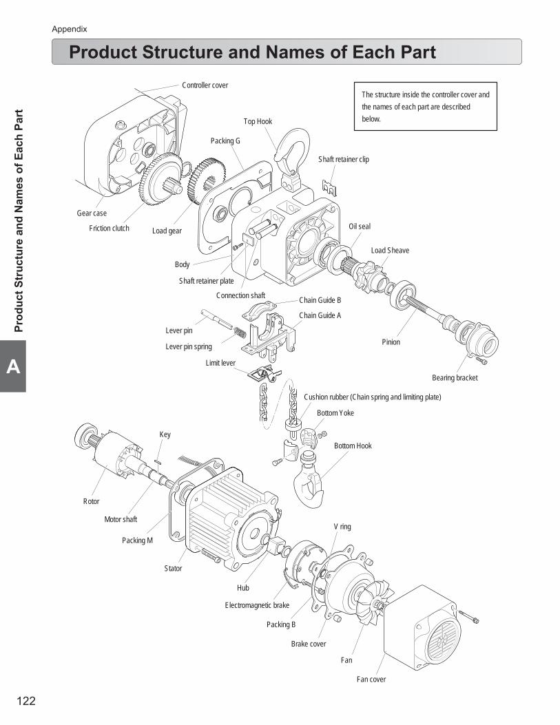
122
Appendix
A
Product Structure and Names of Each Part
Load Sheave
Pinion
Rotor
Stator
Key
Body
Gear case
Friction clutch Load gear
Top Hook
Electromagnetic brake
Brake cover
Fan
Fan cover
Chain Guide A
Chain Guide B
Hub
Packing M
Packing B
V ring
Shaft retainer clip
Cushion rubber (Chain spring and limiting plate)
Bottom Yoke
Bottom Hook
Motor shaft
Shaft retainer plate
Oil seal
Controller cover
Packing G
Bearing bracket
Connection shaft
Lever pin
Lever pin spring
Limit lever
The structure inside the controller cover and the names of each part are described below.
Prod
uct S
truc
ture
and
Nam
es o
f Eac
h Pa
rt
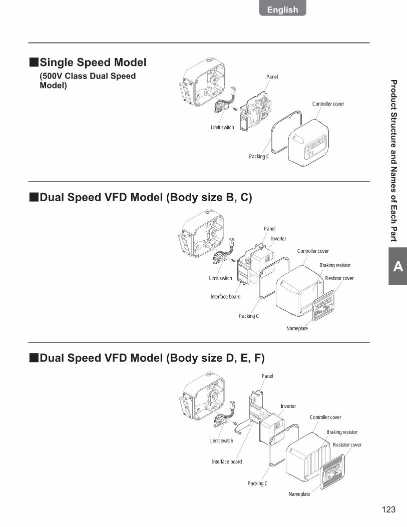
123
A
Single Speed Model ■(500V Class Dual Speed Model)
Dual Speed VFD Model (Body size B, C) ■
Dual Speed VFD Model (Body size D, E, F) ■
Inverter
Controller cover
Panel
Limit switch
Packing C
Braking resistor
Nameplate
Resistor cover
Interface board
Inverter
Controller cover
Braking resistor
Nameplate
Panel
Limit switch Resistor cover
Interface board
Packing C
Product Structure and Nam
es of Each Part
Controller cover
Panel
Limit switch
Packing C
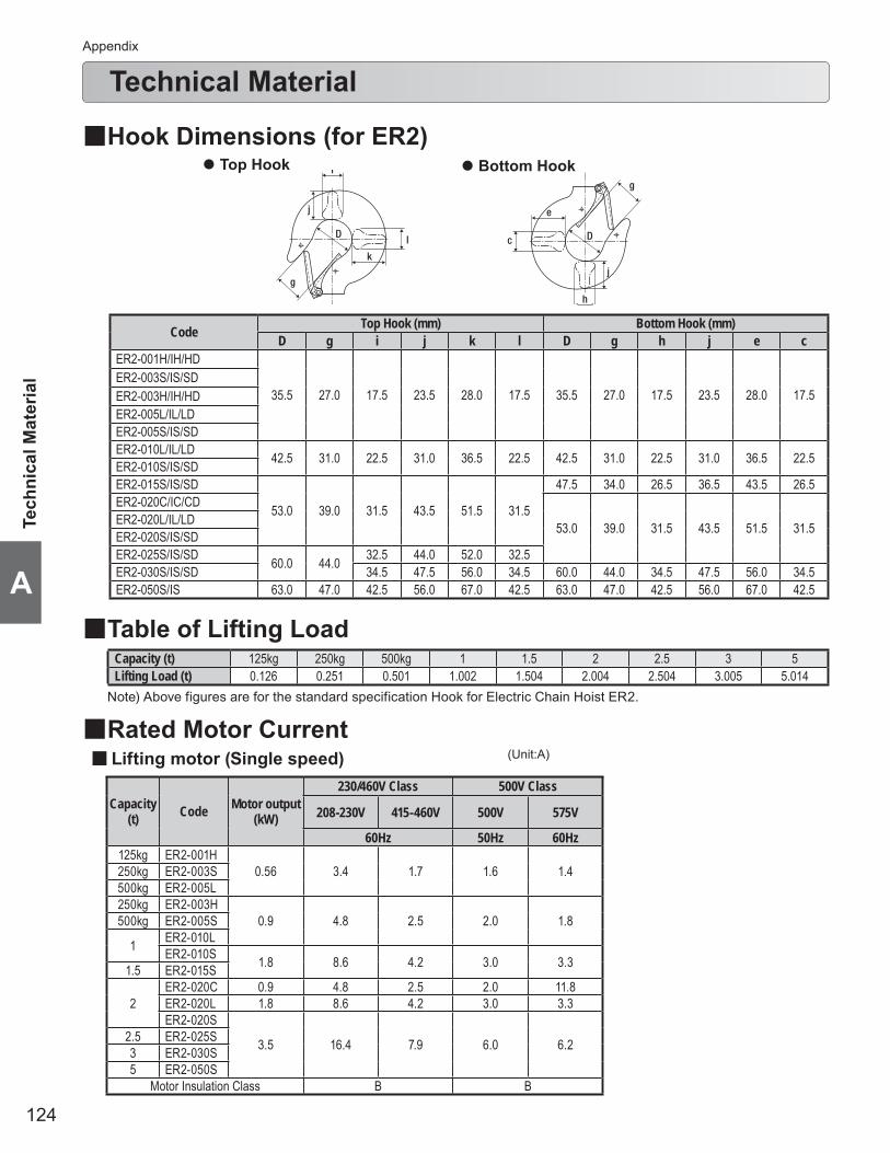
124
Appendix
A
Technical Material
k
i
l
j
D
g
e
h
c
j
D
g
Table of Lifting Load ■
Top Hook ● Bottom Hook ●
Capacity (t) 125kg 250kg 500kg 1 1.5 2 2.5 3 5Lifting Load (t) 0.126 0.251 0.501 1.002 1.504 2.004 2.504 3.005 5.014
Note) Above figures are for the standard specification Hook for Electric Chain Hoist ER2.
Hook Dimensions (for ER2) ■
Rated Motor Current ■Lifting motor (Single speed) ■
Tech
nica
l Mat
eria
l
Capacity(t) Code Motor output
(kW)
230/460V Class 500V Class
208-230V 415-460V 500V 575V
60Hz 50Hz 60Hz125kg ER2-001H
0.56 3.4 1.7 1.6 1.4250kg ER2-003S500kg ER2-005L250kg ER2-003H
0.9 4.8 2.5 2.0 1.8500kg ER2-005S
1 ER2-010LER2-010S 1.8 8.6 4.2 3.0 3.31.5 ER2-015S
2ER2-020C 0.9 4.8 2.5 2.0 11.8ER2-020L 1.8 8.6 4.2 3.0 3.3ER2-020S
3.5 16.4 7.9 6.0 6.22.5 ER2-025S3 ER2-030S5 ER2-050S
Motor Insulation Class B B
(Unit:A)
Code Top Hook (mm) Bottom Hook (mm)D g i j k l D g h j e c
ER2-001H/IH/HD
35.5 27.0 17.5 23.5 28.0 17.5 35.5 27.0 17.5 23.5 28.0 17.5 ER2-003S/IS/SDER2-003H/IH/HDER2-005L/IL/LDER2-005S/IS/SDER2-010L/IL/LD 42.5 31.0 22.5 31.0 36.5 22.5 42.5 31.0 22.5 31.0 36.5 22.5 ER2-010S/IS/SDER2-015S/IS/SD
53.0 39.0 31.5 43.5 51.5 31.5
47.5 34.0 26.5 36.5 43.5 26.5 ER2-020C/IC/CD
53.0 39.0 31.5 43.5 51.5 31.5 ER2-020L/IL/LDER2-020S/IS/SDER2-025S/IS/SD 60.0 44.0 32.5 44.0 52.0 32.5 ER2-030S/IS/SD 34.5 47.5 56.0 34.5 60.0 44.0 34.5 47.5 56.0 34.5 ER2-050S/IS 63.0 47.0 42.5 56.0 67.0 42.5 63.0 47.0 42.5 56.0 67.0 42.5

125
A
Lifting motor (Dual speed) ■
Capacity(t) Code
Motor output (kW)
230/460V Class 500V Class
208-230V 415-460V 500V 575V
60Hz 50Hz 60Hz125kg
MR2-010S/L
0.4 3.2 1.6 1.5 1.1
250kg500kg
11.5 MR2-020S/L22.5 MR2-030S/L35 MR2-050S/L 0.75 5.1 2.5 2.2 1.8
Motor Insulation Class B B
Traveling motor (Single speed) ■
Traveling motor (Dual speed) ■
(to be continued)
Technical Material
Capacity(t) Code
Motor output (kW)
230/460V Class 500V Class
208-230V 415-460V Motoroutput
(kw)
500V 575V
60Hz 50Hz 60Hz125kg
MR2-010IS
0.4 3.4 1.7
0.32/0.08 1.7/1.0 1.1/0.8
250kg500kg
11.5 MR2-020IS22.5 MR2-030IS 0.64/
0.16 1.9/1.5 1.3/1.135 MR2-050IS 0.75 5.4 2.7
Motor Insulation Class B B
Capacity(t) Code
Motor output (kW)
230/460V Class 500V Class
208-230V 415-460V Motor output (kW)
500V 575V
60Hz 50Hz 60Hz125kg ER2-001IH
0.56 3.6 1.8 0.5 1.6/0.9 1.4/0.9250kg ER2-003IS500kg ER2-005IL250kg ER2-003IH
0.9 5.1 2.7 0.9 1.8/1.4 1.7/1.4500kg ER2-005IS
1 ER2-010ILER2-010IS 1.8 9.1 4.5 1.8 3.2/2.2 3.2/2.01.5 ER2-015IS
2ER2-020IC 0.9 5.1 2.7 0.9 1.8/1.4 1.7/1.4ER2-020IL 1.8 9.1 4.5 1.8 3.2/2.2 3.2/2.0ER2-020IS
3.5 17.3 8.3 3.5 6.0/3.7 6.0/3.42.5 ER2-025IS3 ER2-030IS5 ER2-050IS
Motor Insulation Class B B
(Unit:A)
(Unit:A)
(Unit:A)
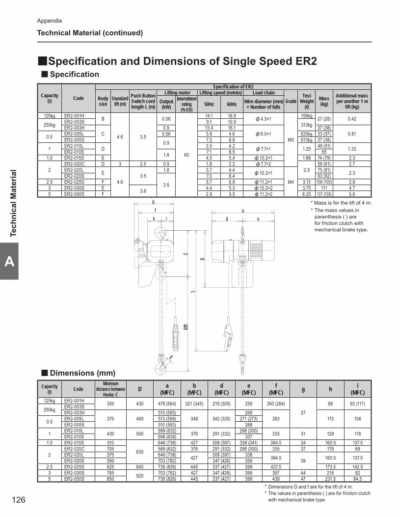
126
Appendix
A
Technical Material (continued)
Specification and Dimensions of Single Speed ER2 ■Specification ■
Dimensions (mm) ■
Capacity (t) Code
Specifi cation of ER2
Body size
Standard lift (m)
Push Button Switch cord length L (m)
Lifting motor Lifting speed (m/min) Load chainGrade
Test Weight
(t)Mass (kg)
Additional mass per another 1 m
lift (kg)Output (kW)
Intermittent rating (% ED)
50Hz 60Hz Wire diameter (mm) × Number of falls
125kg ER2-001H B
4·6 3.5
0.56
60
14.1 16.9 4.3×1
M5
156kg 27 (28) 0.42250kg ER2-003S 9.1 10.9 313kgER2-003H
C0.9 13.4 16.1
6.0×137 (38)
0.810.5 ER2-005L 0.56 3.8 4.6 625kg 33 (37)ER2-005S 0.9 7.3 8.8 613kg 37 (38)
1 ER2-010L D 3.5 4.2 7.7×1 1.25 48 (51) 1.33ER2-010S 1.8 7.1 8.5 551.5 ER2-015S E 4.5 5.4 10.2×1 1.88 74 (79) 2.3
2ER2-020C D 3 2.5 0.9 1.8 2.2 7.7×2
2.559 (61) 2.7
ER2-020L E
4.63.5
1.8 3.7 4.4 10.2×1
M4
75 (81) 2.3ER2-020S
3.5
7.0 8.4 93 (92)2.5 ER2-025S F 5.7 6.8 11.2×1 3.13 106 (105) 2.83 ER2-030S E 3.8 4.4 5.3 10.2×2 3.75 111 4.75 ER2-050S F 2.9 3.5 11.2×2 6.25 137 (135) 5.6
* Mass is for the lift of 4 m.* The mass values in
parenthesis ( ) are for friction clutch with mechanical brake type.
Capacity (t) Code
Minimum distance between
Hooks: CD a
(MFC)b
(MFC)d
(MFC)e
(MFC)f
(MFC) g h i(MFC)
125kg ER2-001H 350 430 478 (564) 321 (345) 219 (305) 259 260 (284)
27
99 93 (117)250kg ER2-003S
ER2-003H370 490
510 (593)348 242 (325)
268283 113 1060.5 ER2-005L 513 (599) 271 (273)
ER2-005S 510 (593) 268
1 ER2-010L 430 550 589 (632) 376 291 (332) 298 (300) 335 31 129 118ER2-010S 598 (639) 3071.5 ER2-015S 510
630
646 (738) 427 308 (397) 338 (341) 384.5 34 160.5 137.5
2ER2-020C 705 589 (632) 376 291 (332) 298 (300) 335 37 178 69ER2-020L 575 646 (738) 427 308 (397) 338 384.5 39 160.5 137.5ER2-020S 590 703 (782) 347 (426) 356
2.5 ER2-025S 625 840 736 (826) 445 337 (427) 399 437.5 173.5 142.53 ER2-030S 785 920 703 (782) 427 347 (426) 356 397 44 216 825 ER2-050S 850 736 (826) 445 337 (427) 399 439 47 231.5 84.5
* Dimensions D and f are for the lift of 4 m.* The values in parenthesis ( ) are for friction clutch
with mechanical brake type.
Tech
nica
l Mat
eria
l
g
lift
CL
Da
edih
f
b

127
A
(to be continued)
Technical Material
r
g
k
lift
C
i
j
t
m
e'
dBe
L
D
u
n
b
Specification and Dimensions of Single Speed ER2M ■Specification ■
Dimensions (mm) ■
Capacity (t) Code
Specification of ER2 Specification of MR2 Other specification
ER2 series
Body size
Standard lift (m)
Push Button Switch cord length L (m)
Lifting motor Lifting speed (m/min) Load chainGrade MR2
series
Traveling motor Traveling speed (m/min) Rail Width: B (mm)
MIinimum Turning Radius (mm)
Mass (kg)
Additional mass per
another 1 m lift (kg)
Output (kW)
Intermittent rating (% ED)
50Hz 60HzWire diameter
(mm) × Number of falls
Output (kW)
Intermittent rating (% ED)
50Hz 60Hz
125kg ER2M001H-S/L ER2-001H B
4·6 3.5
0.56
60
14.1 16.9 4.3×1
M5
MR2-010S(L)
0.440 20
(10)24
(12)
58to
153
800 [3500]
58 (59) 0.42250kg ER2M003S-S/L ER2-003S 9.1 10.9
ER2M003H-S/L ER2-003HC
0.9 13.4 16.1 6.0×1
68 (69)0.810.5 ER2M005L-S/L ER2-005L 0.56 3.8 4.6 64 (67)
0.49 ER2M005S-S/L ER2-005S 0.9 7.3 8.8 68 (69)
1 ER2M010L-S/L ER2-010L D 3.5 4.2 7.7×1 78 (81) 1.33ER2M010S-S/L ER2-010S 1.8 7.1 8.5 851.5 ER2M015S-S/L ER2-015S E 4.5 5.4 10.2×1
MR2-020S(L)
82to
178
800 [1000]
112 (117) 2.3
2ER2M020C-S/L ER2-020C D 3 2.5 0.9 1.8 2.2 7.7×2 97 (99) 2.7ER2M020L-S/L ER2-020L E
4.6
3.51.8 3.7 4.4 10.2×1
M4
113 (118) 2.3ER2M020S-S/L ER2-020S
3.5
7.0 8.4 131 (130)2.5 ER2M025S-S/L ER2-025S F 5.7 6.8 11.2×1 MR2-
030S(L) 100to
178
1000 154 (153) 2.83 ER2M030S-S/L ER2-030S E
3.84.4 5.3 10.2×2 159 4.7
5 ER2M050S-S/L ER2-050S F 2.9 3.5 11.2×2 MR2-050S(L) 0.75 1800 207 (205) 5.6
Capacity (t) Code
Minimum distance between
Hooks: CD b d e e' g i j k m n r t u
125kg ER2M001H-S/L 375 450
315 220 515 17927
95 22 130 205 109 51 31 83
250kg ER2M003S-S/LER2M003H-S/L
395 5100.5 ER2M005L-S/LER2M005S-S/L
1 ER2M010L-S/L 435 550 31ER2M010S-S/L1.5 ER2M015S-S/L 505 630
325 225 520 184
34
110 27 125 212 118 60 36 762ER2M020C-S/L 690 620 37ER2M020L-S/L 570 630 39ER2M020S-S/L 585
2.5 ER2M025S-S/L 620 830 340 226 521 186 125 29 131 215 132 68 43 703 ER2M030S-S/L 765 900 445 ER2M050S-S/L 840 910 400 281 528 192 47 140 44 145 233 150 86 54 56
* Dimensions D is for the lift of 4 m.
* Mass is for the lift of 4 m.* The traveling speed values in
parenthesis ( ) are for the low speed.* The values in brackets [ ] are for the
minimum turning radius of the value in the brackets.
* The mass values in parenthesis ( ) are for friction clutch with mechanical brake type.

128
Appendix
A
Technical Material (continued)
Tech
nica
l Mat
eria
l
nb
k
ae B
CLift
LD
qp
tr
g
om
hij
Specification and Dimensions of Single Speed ER2SP ■Specification ■
Dimensions (mm) ■
Capacity (t) Code
Specification of ER2 Specification of TSP (plain trolley) Specification of ER2SP
ER2 series
Body size
Standard lift (m)
Push Button Switch cord length L (m)
Lifting motor Lifting speed (m/min) Load chainGrade TSP
seriesHand Chain length:
E (m)Rail Width:
B (mm)
MIinimum Turning Radius (mm)
Mass (kg)
Additional mass per
another 1 m lift (kg)
Output (kW)
Intermittent rating (% ED)
50Hz 60HzWire diameter
(mm) × Number of falls
125kg ER2SP001H ER2-001H B
4·6 3.5
0.56
60
14.1 16.9 4.3×1
M5
TSP005 50 to 102 1100
32 (33) 0.42250kg ER2SP003S ER2-003S 9.1 10.9
ER2SP003H ER2-003HC
0.9 13.4 16.1 6.0×1
42 (43)0.810.5 ER2SP005L ER2-005L 0.56 3.8 4.6 38 (42)
ER2SP005S ER2-005S 0.9 7.3 8.8 42 (43)
1 ER2SP010L ER2-010L D 3.5 4.2 7.7×1 TSP010 58 to 127 1300 56 (59) 1.33ER2SP010S ER2-010S 1.8 7.1 8.5 631.5 ER2SP015S ER2-015S E 4.5 5.4 10.2×1
TSP02082 to 153
1500
87 (93) 2.3
2ER2SP020C ER2-020C D 3 2.5 0.9 1.8 2.2 7.7×2 73 (75) 2.7ER2SP020L ER2-020L E
4·63.5
1.8 3.7 4.4 10.2×1
M4
88 (94) 2.3ER2SP020S ER2-020S
3.5
7.0 8.4 107 (106)2.5 ER2SP025S ER2-025S F 5.7 6.8 11.2×1 TSP030 1700 130 (129) 2.83 ER2SP030S ER2-030S E 3.8 4.4 5.3 10.2×2 134 (133) 4.75 ER2SP050S ER2-050S F 2.9 3.5 11.2×2 TSP050 100 to 178 2300 187 (185) 5.6
* Mass is for the lift of 4 m.* The mass values in
parenthesis ( ) are for friction clutch with mechanical brake type.
Capacity (t) Code
Minimum distance between
Hooks: CD a b e g h i j k m n o p q r t
125kg ER2SP001H 395 470
204 182 46 27 82 60 21 76 47.5 84 42
10
54 38 22250kg ER2SP003SER2SP003H
415 5300.5 ER2SP005LER2SP005S
1 ER2SP010L 470 590 249 236 56 31 106 71 28 95 56 112 50 69 50 25ER2SP010S1.5 ER2SP015S 570 690
300 280 69
34
127 85 34 112 71 131 63 83 62 322ER2SP020C 695 620 37ER2SP020L 635 690 39ER2SP020S 650
2.5 ER2SP025S 680 890 320 324 79 148 100 36 134 80 152 74 102 68 363 ER2SP030S 780 910 445 ER2SP050S 840 297 400 53 47 169 118 46 144 81 178 70 104 88 54
* Dimensions D is for the lift of 4 m.

129
A
Technical Material
Capacity (t) Code
Specification of ER2 Specification of TSG (geared trolley) Specification of ER2SG
ER2 series
Body size
Standard lift (m)
Push Button Switch cord length L (m)
Lifting motor Lifting speed (m/min) Load chainGrade TSG
seriesHand Chain length:
E (m)Rail Width: B
(mm)
MIinimum Turning Radius (mm)
Mass (kg)
Additional mass per another 1 m lift (kg)
Output (kW)
Intermittent rating (% ED)
50Hz 60HzWire diameter
(mm) × Number of falls
125kg ER2SG001H ER2-001H B
4·6 3.5
0.56
60
14.1 16.9 4.3×1
M5TSG010
3.7 · 5.7
58 to 127 1300
41 (42) 1.4250kg ER2SG003S ER2-003S 9.1 10.9
ER2SG003H ER2-003HC
0.9 13.4 16.1 6.0×1
51 (52)1.70.5 ER2SG005L ER2-005L 0.56 3.8 4.6 47 (50)ER2SG005S ER2-005S 0.9 7.3 8.8
1 ER2SG010L ER2-010L D 3.5 4.2 7.7×1 61 (64) 2.3ER2SG010S ER2-010S 1.8 7.1 8.5 681.5 ER2SG015S ER2-015S E 4.5 5.4 10.2×1
TSG02082 to 153
1500
92 (98) 3.2
2ER2SG020C ER2-020C D 3 2.5 0.9 1.8 2.2 7.7×2 78 (80) 3.6ER2SG020L ER2-020L E
4·63.5
1.8 3.7 4.4 10.2×1
M4
93 (99) 3.2ER2SG020S ER2-020S
3.5
7.0 8.4 112 (111)2.5 ER2SG025S ER2-025S F 5.7 6.8 11.2×1 TSG030 1700 135 (134) 3.73 ER2SG030S ER2-030S E 3.8 4.6 5.5 10.2×2 139 (138) 5.65 ER2SG050S ER2-050S F 2.9 3.5 11.2×2 TSG050 4.2 · 6.2 100 to 178 2300 194 (192) 6.5
* Mass is for the lift of 4 m.* The mass values in
parenthesis ( ) are for friction clutch with mechanical brake type.
B ea
u
LE
D
bn
kk'
CLift
qp
tr
g
om
hij
Specification and Dimensions of Single Speed ER2SG ■Specification ■
Dimensions (mm) ■Capacity
(t) CodeMinimum
distance between Hooks: C
D a b e g h i j k k' m n o p q r t u
125kg ER2SG001H 415 490
345 236 15227
106 71 28 95 107 56 112 50
10
69 50 25
183
250kg ER2SG003SER2SG003H
435 5500.5 ER2SG005LER2SG005S
1 ER2SG010L 470 590 31ER2SG010S1.5 ER2SG015S 570 690
385 280 154
34
127 85 34 112 109 71 131 63 83 62 322ER2SG020C 695 620 37ER2SG020L 635 690 39ER2SG020S 650
2.5 ER2SG025S 680 890 398 324 157 148 100 36 134 115 80 152 74 102 68 363 ER2SG030S 780 910 445 ER2SG050S 840 401 400 156 47 169 118 46 144 131 81 178 70 104 88 54
* Dimensions D is for the lift of 4 m.(to be continued)
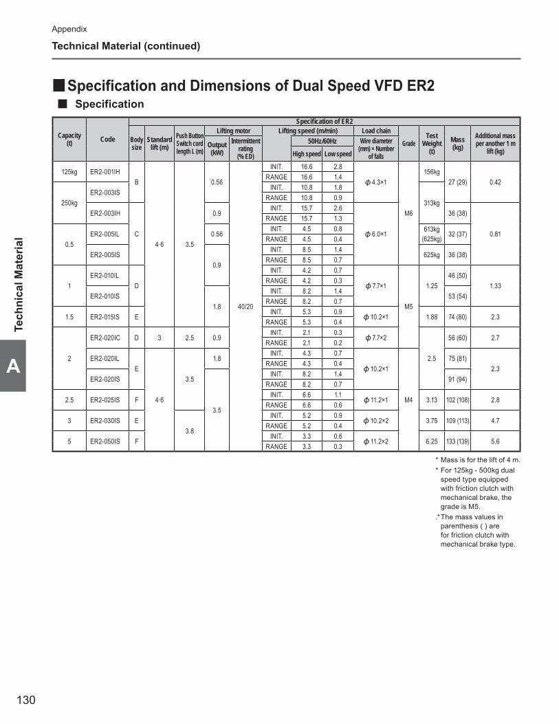
130
Appendix
A
Technical Material (continued)
Tech
nica
l Mat
eria
l
Specification and Dimensions of Dual Speed VFD ER2 ■Specification ■
Capacity (t) Code
Specifi cation of ER2
Body size
Standard lift (m)
Push Button Switch cord length L (m)
Lifting motor Lifting speed (m/min) Load chain
GradeTest
Weight(t)
Mass (kg)
Additional mass per another 1 m
lift (kg)Output (kW)
Intermittent rating (% ED)
50Hz/60Hz Wire diameter (mm) × Number
of fallsHigh speed Low speed
125kg ER2-001IHB
4·6 3.5
0.56
40/20
INIT. 16.6 2.8
4.3×1
M6
156kg27 (29) 0.42
RANGE 16.6 1.4
250kgER2-003IS
INIT. 10.8 1.8
313kgRANGE 10.8 0.9
ER2-003IH
C
0.9INIT. 15.7 2.6
6.0×1
36 (38)
0.81
RANGE 15.7 1.3
0.5ER2-005IL 0.56
INIT. 4.5 0.8 613kg (625kg) 32 (37)
RANGE 4.5 0.4
ER2-005IS0.9
INIT. 8.5 1.4 625kg 36 (38)
RANGE 8.5 0.7
1ER2-010IL
D
INIT. 4.2 0.7
7.7×1
M5
1.2546 (50)
1.33RANGE 4.2 0.3
ER2-010IS1.8
INIT. 8.2 1.4 53 (54)
RANGE 8.2 0.7
1.5 ER2-015IS EINIT. 5.3 0.9
10.2×1 1.88 74 (80) 2.3RANGE 5.3 0.4
2
ER2-020IC D 3 2.5 0.9INIT. 2.1 0.3
7.7×2
2.5
56 (60) 2.7RANGE 2.1 0.2
ER2-020ILE
4·6
3.5
1.8INIT. 4.3 0.7
10.2×1
M4
75 (81)2.3
RANGE 4.3 0.4
ER2-020IS
3.5
INIT. 8.2 1.4 91 (94)
RANGE 8.2 0.7
2.5 ER2-025IS FINIT. 6.6 1.1
11.2×1 3.13 102 (108) 2.8RANGE 6.6 0.6
3 ER2-030IS E3.8
INIT. 5.2 0.9 10.2×2 3.75 109 (113) 4.7
RANGE 5.2 0.4
5 ER2-050IS FINIT. 3.3 0.6
11.2×2 6.25 133 (139) 5.6RANGE 3.3 0.3
* Mass is for the lift of 4 m.* For 125kg - 500kg dual
speed type equipped with friction clutch with mechanical brake, the grade is M5.
.* The mass values in parenthesis ( ) are for friction clutch with mechanical brake type.

131
A
(to be continued)
Technical Material
Dimensions (mm) ■Capacity
(t) CodeMinimum
distance between Hooks: C
D a(MFC) b d
(MFC)e
(MFC) f g h i
125kg ER2-001IH 350 430 535 (564) 345 276 (305) 259 284
27
99 117250kg ER2-003IS
ER2-003IH370 490
568 (593)348 300 (325)
268283 113 1060.5 ER2-005IL 571 (598) 271 (273)
ER2-005IS 568 (593) 268
1 ER2-010IL 430 550 614 (632) 376 316 (332) 298 (300) 335 31 129 118ER2-010IS 623 (639) 3071.5 ER2-015IS 510
630
710 (737) 427 372 (397) 338 (340) 384.5 34 160.5 137.5
2ER2-020IC 705 614 (632) 376 316 (332) 298 (300) 335 37 178 69ER2-020IL 575 710 (737) 427 372 (397) 338 (340) 384.5 39 160.5 137.5ER2-020IS 590 767 (782) 411 (426) 356
2.5 ER2-025IS 625 840 800 (826) 445 401 (427) 399 437.5 173.5 142.53 ER2-030IS 785 920 767 (782) 427 411 (426) 356 397 44 216 825 ER2-050IS 850 800 (826) 445 401 (427) 399 439 47 231.5 84.5
* Dimensions D and f are for the lift of 4 m.* The values in parenthesis ( ) are for friction clutch
with mechanical brake type.
h
g
lift
C
L
ed
a
D
i
f
b
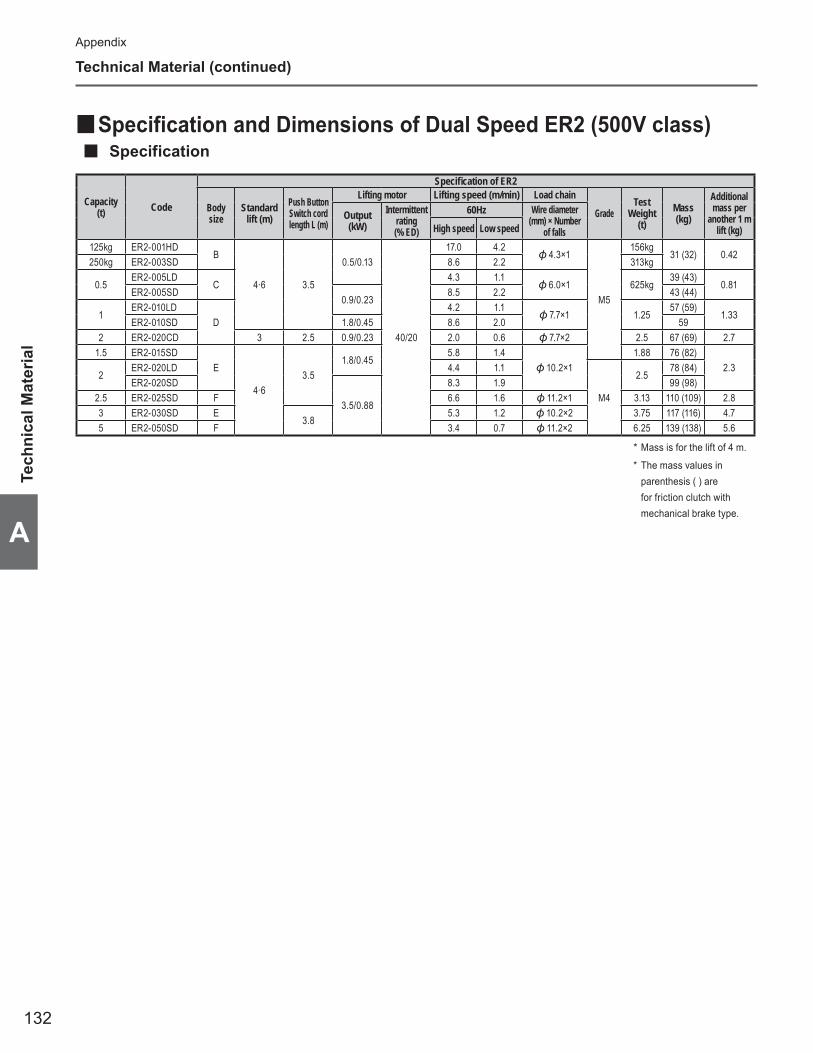
132
Appendix
A
Specification and Dimensions of Dual Speed ER2 (500V class) ■Specification ■
Capacity (t) Code
Specifi cation of ER2
Body size
Standard lift (m)
Push Button Switch cord length L (m)
Lifting motor Lifting speed (m/min) Load chain
GradeTest
Weight(t)
Mass (kg)
Additional mass per
another 1 m lift (kg)
Output (kW)
Intermittent rating (% ED)
60Hz Wire diameter (mm) × Number
of fallsHigh speed Low speed
125kg ER2-001HDB
4·6 3.5
0.5/0.13
40/20
17.0 4.2 4.3×1
M5
156kg31 (32) 0.42
250kg ER2-003SD 8.6 2.2 313kg
0.5ER2-005LD
C4.3 1.1
6.0×1 625kg39 (43)
0.81ER2-005SD
0.9/0.238.5 2.2 43 (44)
1ER2-010LD
D4.2 1.1
7.7×1 1.2557 (59)
1.33ER2-010SD 1.8/0.45 8.6 2.0 59
2 ER2-020CD 3 2.5 0.9/0.23 2.0 0.6 7.7×2 2.5 67 (69) 2.71.5 ER2-015SD
E
4·63.5
1.8/0.455.8 1.4
10.2×11.88 76 (82)
2.32
ER2-020LD 4.4 1.1
M4
2.578 (84)
ER2-020SD
3.5/0.88
8.3 1.9 99 (98)2.5 ER2-025SD F 6.6 1.6 11.2×1 3.13 110 (109) 2.83 ER2-030SD E
3.85.3 1.2 10.2×2 3.75 117 (116) 4.7
5 ER2-050SD F 3.4 0.7 11.2×2 6.25 139 (138) 5.6
* Mass is for the lift of 4 m.
* The mass values in parenthesis ( ) are for friction clutch with mechanical brake type.
Technical Material (continued)
Tech
nica
l Mat
eria
l
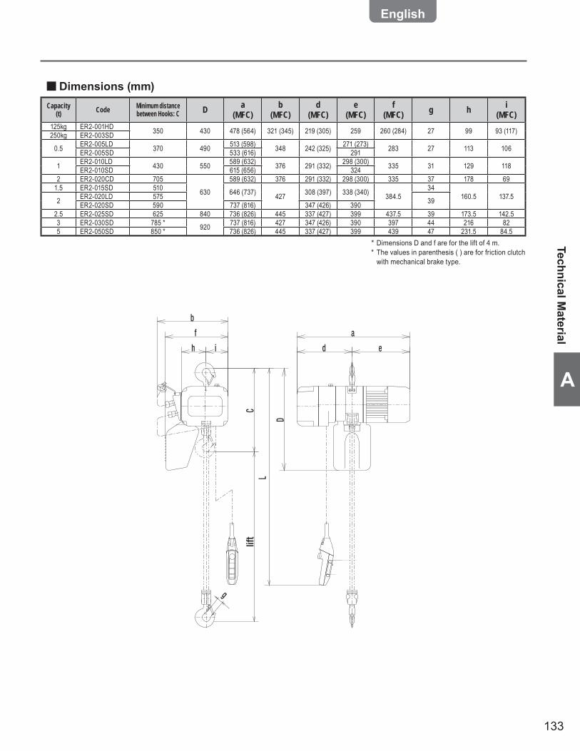
133
A
Dimensions (mm) ■Capacity
(t) Code Minimum distance between Hooks: C D a
(MFC)b
(MFC)d
(MFC)e
(MFC)f
(MFC) g h i(MFC)
125kg ER2-001HD 350 430 478 (564) 321 (345) 219 (305) 259 260 (284) 27 99 93 (117)250kg ER2-003SD
0.5 ER2-005LD 370 490 513 (598) 348 242 (325) 271 (273) 283 27 113 106ER2-005SD 533 (616) 291
1 ER2-010LD 430 550 589 (632) 376 291 (332) 298 (300) 335 31 129 118ER2-010SD 615 (656) 3242 ER2-020CD 705
630
589 (632) 376 291 (332) 298 (300) 335 37 178 691.5 ER2-015SD 510 646 (737) 427 308 (397) 338 (340) 384.5
34160.5 137.52 ER2-020LD 575 39ER2-020SD 590 737 (816) 347 (426) 390
2.5 ER2-025SD 625 840 736 (826) 445 337 (427) 399 437.5 39 173.5 142.53 ER2-030SD 785 * 920 737 (816) 427 347 (426) 390 397 44 216 825 ER2-050SD 850 * 736 (826) 445 337 (427) 399 439 47 231.5 84.5
* Dimensions D and f are for the lift of 4 m.* The values in parenthesis ( ) are for friction clutch
with mechanical brake type.
g
lift
CL
D
a
edih
f
b
Technical Material

134
Appendix
A
Specification and Dimensions of Dual Speed VFD ER2M ■Specification ■
Capacity (t) Code
Specification of MR2 Specification of ER2M
MR2 seriesTraveling motor Traveling speed (m/min)
Rail Width: B (mm)
MIinimum Turning Radius
(mm)Mass (kg)
Additional mass per another 1 m lift (kg)Output
(kW)Intermittent
rating (% ED)
50Hz/60HzHigh speed Low speed
125kg ER2M-001IH-IS
MR2-010IS
0.427/13
INIT.
24
4
58 to 153 800 [3500]
59 (61) 0.42250kg
ER2M-003IS-ISER2M-003IH-IS 69 (71)
0.810.5
ER2M005IL-IS 65 (69)ER2M005IS-IS 69 (71)
1ER2M010IL-IS 78 (82)
1.33ER2M010IS-IS 85 (86)
1.5 ER2M015IS-IS
MR2-020IS82 to 178
800 [1000]
113 (120) 2.3
2ER2M020IC-IS 97 (101) 2.7ER2M020IL-IS 114 (121)
2.3
RANGE 2.4
ER2M020IS-IS 131 (134)2.5 ER2M025IS-IS
MR2-030IS 1000153 (159) 2.8
3 ER2M030IS-IS 159 (164) 4.75 ER2M050IS-IS MR2-050IS 0.75 100 to 178 1800 205 (211) 5.6
* Mass is for the lift of 4 m.* Be careful that the values in brackets [ ] are for the minimum turning radius of the value in the brackets.* For 125kg - 500kg dual speed type equipped with friction clutch with mechanical brake, the grade is M5.* The mass values in parenthesis ( ) are for friction clutch with mechanical brake type.
Technical Material (continued)
Tech
nica
l Mat
eria
l
Capacity (t) Code
Specification of ER2
ER2 series Body size
Standard lift (m)
Push Button Switch cord length L (m)
Lifting motor Lifting speed (m/min) Load chain
GradeOutput (kW)
Intermittent rating (% ED)
50Hz/60Hz Wire diameter (mm) × Number of fallsHigh speed Low speed
125kg ER2M-001IH-IS/IL ER2-001IHB
4·6 3.5
0.56
40/20
INIT. 16.6 2.8
4.3×1
M6
RANGE 16.6 1.4
250kgER2M-003IS-IS/IL ER2-003IS
INIT. 10.8 1.8 RANGE 10.8 0.9
ER2M-003IH-IS/IL ER2-003IH
C
0.9INIT. 15.7 2.6
6.0×1
RANGE 15.7 1.3
0.5ER2M005IL-IS/IL ER2-005IL 0.56
INIT. 4.5 0.8 RANGE 4.5 0.4
ER2M005IS-IS/IL ER2-005IS0.9
INIT. 8.5 1.4 RANGE 8.5 0.7
1ER2M010IL-IS/IL ER2-010IL
D
INIT. 4.2 0.7
0.77×1
M5
RANGE 4.2 0.3
ER2M010IS-IS/IL ER2-010IS1.8
INIT. 8.2 1.4 RANGE 8.2 0.7
1.5 ER2M015IS-IS/IL ER2-015IS EINIT. 5.3 0.9
10.2×1RANGE 5.3 0.4
2
ER2M020IC-IS/IL ER2-020IC D 3 2.5 0.9INIT. 2.1 0.3
0.77×2RANGE 2.1 0.2
ER2M020IL-IS/IL ER2-020ILE
4·6
3.5
1.8INIT. 4.3 0.7
10.2×1
M4
RANGE 4.3 0.4
ER2M020IS-IS/IL ER2-020IS
3.5
INIT. 8.2 1.4 RANGE 8.2 0.7
2.5 ER2M025IS-IS/IL ER2-025IS FINIT. 6.6 1.1
11.2×1RANGE 6.6 0.6
3 ER2M030IS-IS/IL ER2-030IS E3.8
INIT. 5.2 0.9 10.2×2
RANGE 5.2 0.4
5 ER2M050IS-IS/IL ER2-050IS FINIT. 3.4 0.6
11.2×2RANGE 3.4 0.3

135
A
r
g
k
C
i
j
t
m
e'
dBe
L
D
u
n
b
lift
Dimensions (mm) ■Other dimensions are the same with those of Single Speed ER2M.
(to be continued)
Technical Material

136
Appendix
A
Specification and Dimensions of Dual Speed ER2M (500V class) ■Specification ■
Capacity (t) Code
Specification of ER2
ER2 series Body size Standard lift (m)
Push Button Switch cord length L (m)
Lifting motor Traveling speed (m/min) Load chain
GradeOutput (kW)
Intermittent rating (% ED)
60Hz Wire diameter (mm) × Number of fallsHigh speed Low speed
125kg ER2M001HD-SD ER2-001HDB
4·6 3.5
0.5/0.13
40/20
17.0 4.2 4.3×1
M5
250kg ER2M003SD-SD ER2-003SD 8.6 2.2
0.5ER2M005LD-SD ER2-005LD
C4.3 1.1
6.0×1ER2M005SD-SD ER2-005SD
0.9/0.238.5 2.2
1ER2M010LD-SD ER2-010LD
D4.2 1.1
7.7×1ER2M010SD-SD ER2-010SD 1.8/0.45 8.6 2.0
2 ER2M020CD-SD ER2-020CD 3 2.5 0.9/0.23 2.0 0.5 7.7×21.5 ER2M015SD-SD ER2-015SD
E
4·63.5
1.8/0.455.8 1.4
10.2×12
ER2M020LD-SD ER2-020LD 4.4 1.1
M4ER2M020SD-SD ER2-020SD
3.5/0.88
8.3 1.92.5 ER2M025SD-SD ER2-025SD F 6.6 1.6 11.2×13 ER2M030SD-SD ER2-030SD E
3.85.3 1.2 10.2×2
5 ER2M050SD-SD ER2-050SD F 3.4 0.7 11.2×2
Capacity (t) Code
Specification of MR2 Specification of ER2M
MR2 series
Traveling motor Traveling speed (m/min)Rail Width:
B (mm)MIinimum
Turning Radius (mm)
Mass (kg) Additional mass per another 1 m lift (kg)Output (kW)
Intermittent rating (% ED) 50Hz 60Hz
125kg ER2M001HD-SD
MR2-010SD
0.32/0.08
27/13 20/5 24/6
58 to 153 800 [3500]
66 (67) 0.42250kg ER2M003SD-SD
0.5ER2M005LD-SD 74 (77)
0.81ER2M005SD-SD 77 (78)
1ER2M010LD-SD 90 (93)
1.33ER2M010SD-SD 93
2 ER2M020CD-SD
MR2-020SD 82 to 178 800[1000]
109 (112) 2.7
1.5 ER2M015SD-SD 118 (124)
2.32
ER2M020LD-SD 119 (125)
ER2M020SD-SD 140
2.5 ER2M025SD-SDMR2-030SD
0.64/0.1682 to 178 1000
161 2.8
3 ER2M030SD-SD 168 (167) 4.7
5 ER2M050SD-SD MR2-050SD 100 to 178 1800 213 (212) 5.6
* Mass is for the lift of 4 m.* Be careful that the values in brackets [ ] are for the minimum turning radius of the value in the brackets.* The mass values in parenthesis ( ) are for friction clutch with mechanical brake type.
Tech
nica
l Mat
eria
l
Technical Material (continued)

137
A
r
g
k
lift
C
i
j
t
m
e'
dBe
L
D
u
n
b
Dimensions (mm) ■
Capacity (t) Code Minimum distance
between Hooks: C D b d e e' g i j k m n r t u
125kg ER2M001HD-SD 375 450
315 268 515 17927
95 22 130 205 109 51 31 83
250kg ER2M003SD-SD
0.5 ER2M005LD-SD 395 510ER2M005SD-SD
1 ER2M010LD-SD 435 550 31ER2M010SD-SD2 ER2M020CD-SD 690 620
325 273 520 184
37
110 27 125 212 118 60 36 761.5 ER2M015SD-SD 505630 34
2 ER2M020LD-SD 570ER2M020SD-SD 585 392.5 ER2M025SD-SD 620 830 340 274 521 186 125 29 131 215 132 68 43 703 ER2M030SD-SD 765 * 900 44
5 ER2M050SD-SD 840 * 910 400 281 528 192 47 140 44 145 233 150 86 54 56
* Dimensions D is for the lift of 4 m.
Technical Material

138
Appendix
A
Technical Material (continued)
Conversion Table between Lift/Travel/Speed (m/s ■ m/min)Converted value (m/s)
Conventional value (m/min)
Converted value (m/s)
Conventional value (m/min)
Converted value (m/s)
Conventional value (m/min)
Converted value (m/s)
Conventional value (m/min)
Converted value (m/s)
Conventional value (m/min)
Converted value (m/s)
Conventional value (m/min)
0.067 4.0 0.133 8.0 0.200 12.0 0.267 16.0 0.333 20.0 0.002 0.1 0.068 4.1 0.135 8.1 0.202 12.1 0.268 16.1 0.335 20.1 0.003 0.2 0.070 4.2 0.137 8.2 0.203 12.2 0.270 16.2 0.337 20.2 0.005 0.3 0.072 4.3 0.138 8.3 0.205 12.3 0.272 16.3 0.338 20.3 0.007 0.4 0.073 4.4 0.140 8.4 0.207 12.4 0.273 16.4 0.340 20.4 0.008 0.5 0.075 4.5 0.142 8.5 0.208 12.5 0.275 16.5 0.342 20.5 0.010 0.6 0.077 4.6 0.143 8.6 0.210 12.6 0.277 16.6 0.343 20.6 0.012 0.7 0.078 4.7 0.145 8.7 0.212 12.7 0.278 16.7 0.345 20.7 0.013 0.8 0.080 4.8 0.147 8.8 0.213 12.8 0.280 16.8 0.347 20.8 0.015 0.9 0.082 4.9 0.148 8.9 0.215 12.9 0.282 16.9 0.348 20.9 0.017 1.0 0.083 5.0 0.150 9.0 0.217 13.0 0.283 17.0 0.350 21.0 0.018 1.1 0.085 5.1 0.152 9.1 0.218 13.1 0.285 17.1 0.352 21.1 0.020 1.2 0.087 5.2 0.153 9.2 0.220 13.2 0.287 17.2 0.353 21.2 0.022 1.3 0.088 5.3 0.155 9.3 0.222 13.3 0.288 17.3 0.355 21.3 0.023 1.4 0.090 5.4 0.157 9.4 0.223 13.4 0.290 17.4 0.357 21.4 0.025 1.5 0.092 5.5 0.158 9.5 0.225 13.5 0.292 17.5 0.358 21.5 0.027 1.6 0.093 5.6 0.160 9.6 0.227 13.6 0.293 17.6 0.360 21.6 0.028 1.7 0.095 5.7 0.162 9.7 0.228 13.7 0.295 17.7 0.362 21.7 0.030 1.8 0.097 5.8 0.163 9.8 0.230 13.8 0.297 17.8 0.363 21.8 0.032 1.9 0.098 5.9 0.165 9.9 0.232 13.9 0.298 17.9 0.365 21.9 0.033 2.0 0.100 6.0 0.167 10.0 0.233 14.0 0.300 18.0 0.367 22.0 0.035 2.1 0.102 6.1 0.168 10.1 0.235 14.1 0.302 18.1 0.368 22.1 0.037 2.2 0.103 6.2 0.170 10.2 0.237 14.2 0.303 18.2 0.370 22.2 0.038 2.3 0.105 6.3 0.172 10.3 0.238 14.3 0.305 18.3 0.372 22.3 0.040 2.4 0.107 6.4 0.173 10.4 0.240 14.4 0.307 18.4 0.373 22.4 0.042 2.5 0.108 6.5 0.175 10.5 0.242 14.5 0.308 18.5 0.375 22.5 0.043 2.6 0.110 6.6 0.177 10.6 0.243 14.6 0.310 18.6 0.377 22.6 0.045 2.7 0.112 6.7 0.178 10.7 0.245 14.7 0.312 18.7 0.378 22.7 0.047 2.8 0.113 6.8 0.180 10.8 0.247 14.8 0.313 18.8 0.380 22.8 0.048 2.9 0.115 6.9 0.182 10.9 0.248 14.9 0.315 18.9 0.382 22.9 0.050 3.0 0.117 7.0 0.183 11.0 0.250 15.0 0.317 19.0 0.383 23.0 0.052 3.1 0.118 7.1 0.185 11.1 0.252 15.1 0.318 19.1 0.385 23.1 0.053 3.2 0.120 7.2 0.187 11.2 0.253 15.2 0.320 19.2 0.387 23.2 0.055 3.3 0.122 7.3 0.188 11.3 0.255 15.3 0.322 19.3 0.388 23.3 0.057 3.4 0.123 7.4 0.190 11.4 0.257 15.4 0.323 19.4 0.390 23.4 0.058 3.5 0.125 7.5 0.192 11.5 0.258 15.5 0.325 19.5 0.392 23.5 0.060 3.6 0.127 7.6 0.193 11.6 0.260 15.6 0.327 19.6 0.393 23.6 0.062 3.7 0.128 7.7 0.195 11.7 0.262 15.7 0.328 19.7 0.395 23.7 0.063 3.8 0.130 7.8 0.197 11.8 0.263 15.8 0.330 19.8 0.397 23.8 0.065 3.9 0.132 7.9 0.198 11.9 0.265 15.9 0.332 19.9 0.398 23.9
0.400 24.0 0.500 30.0 0.600 36.0
Tech
nica
l Mat
eria
l

139
A
Clearance between Trolley and Applicable Rail ■Motorized Trolley ■
Manual Trolley ■
B
A
A
B
I-beam sizeClearance between trolley and rail
TSP TSP/TSG~500kg ~1t ~2t ~3t ~5t
H B t A B A B A B A B A B100 75 5 13.3 12.5 21.1 11.0 × × × × × ×125 75 5.5 10.8 12.25 19.5 10.75 × × × × × ×150 75 5.5 10.8 12.25 19.5 10.75 × × × × × ×180 100 6 11.2 24.5 19.9 23 25.6 18.5 × × × ×200 100 7 11.1 24 19.9 22.5 25.6 18 × × × ×150 125 8.5 7.9 35.75 16.7 34.25 22.4 29.75 24.1 27.25 × ×250 125 7.5 9.4 36.25 18.2 34.75 23.9 30.25 25.6 27.75 35.2 20.25250 125 10 2.9 35 11.6 33.5 17.3 29 19 26.5 28.6 19200 150 9 6.8 48 15.6 46.5 21.2 42 22.9 39.5 32.5 32300 150 8 9.8 48.5 18.6 47 24.3 42.5 26 40 35.6 32.5300 150 10 4.2 47.5 13 46 18.7 41.5 20.4 39 30.5 31.5300 150 11.5 0.7 46.75 9.5 45.25 15.2 40.75 16.9 38.25 26.4 30.75350 150 9 7.8 48 16.6 46.5 22.2 42 23.9 39.5 33.5 32350 150 12 × × 7.5 45 13.1 40.5 14.8 38 24.4 30.5400 150 10 4.7 47.5 13.5 46 19.2 41.5 20.9 39 30.5 31.5400 150 12.5 × × 6.4 44.75 12.1 40.25 13.8 37.75 23.4 30.25450 175 11 3.6 59.5 12.4 58 18.1 53.5 19.7 51 29.3 43.5450 175 13 × × 5.3 57 11 52.5 12.7 50 22.3 42.5600 190 13 × × 7.8 64.5 13.5 60 15.2 57.5 24.8 50600 190 16 × × × × 3.4 58.5 5.1 56 14.7 48.5
I-beam sizeClearance between trolley and rail
~1t ~2t ~3t ~5tSingle DoubleH B t A B A B A A B A B
100 75 5 × × × × × × × × ×125 75 5.5 13.8 9.75 × × × × × × ×150 75 5.5 13.8 9.75 × × × × × × ×180 100 6 14.2 22 18.6 19.5 × × × × ×200 100 7 14.1 21.5 18.6 19 × × × × ×150 125 8.5 11 33.25 15.4 30.75 × × × × ×250 125 7.5 12.5 33.75 16.9 31.25 10.6 11.8 28.75 32.4 18.25250 125 10 5.9 32.5 10.3 30 17.2 18.4 27.5 25.8 17200 150 9 9.8 45.5 14.3 43 14.5 15.7 40.5 29.7 30300 150 8 12.9 46 17.3 43.5 17.6 18.8 41 32.8 30.5300 150 10 7.3 45 11.7 42.5 12.0 13.2 40 27.2 29.5300 150 11.5 3.7 44.25 8.2 41.75 8.5 9.7 39.25 23.7 28.75350 150 9 10.8 45.5 15.4 43 15.5 16.7 40.5 30.7 30350 150 12 1.7 44 6.2 41.5 6.4 7.6 39 21.6 28.5400 150 10 7.8 45 12.2 42.5 12.5 13.7 40 27.7 29.5400 150 12.5 0.7 43.75 5.1 41.25 5.4 6.6 38.75 20.6 28.25450 175 11 × × 11.1 54.5 11.4 12.6 52 19.5 41.5450 175 13 × × 4.5 53.5 4.3 5.5 51 26.6 40.5600 190 13 × × 6.5 61 6.8 8 58.5 22.0 48600 190 16 × × × × × × × 11.9 46.5
(to be continued)
Technical Material
(Unit:mm)
(Unit:mm)
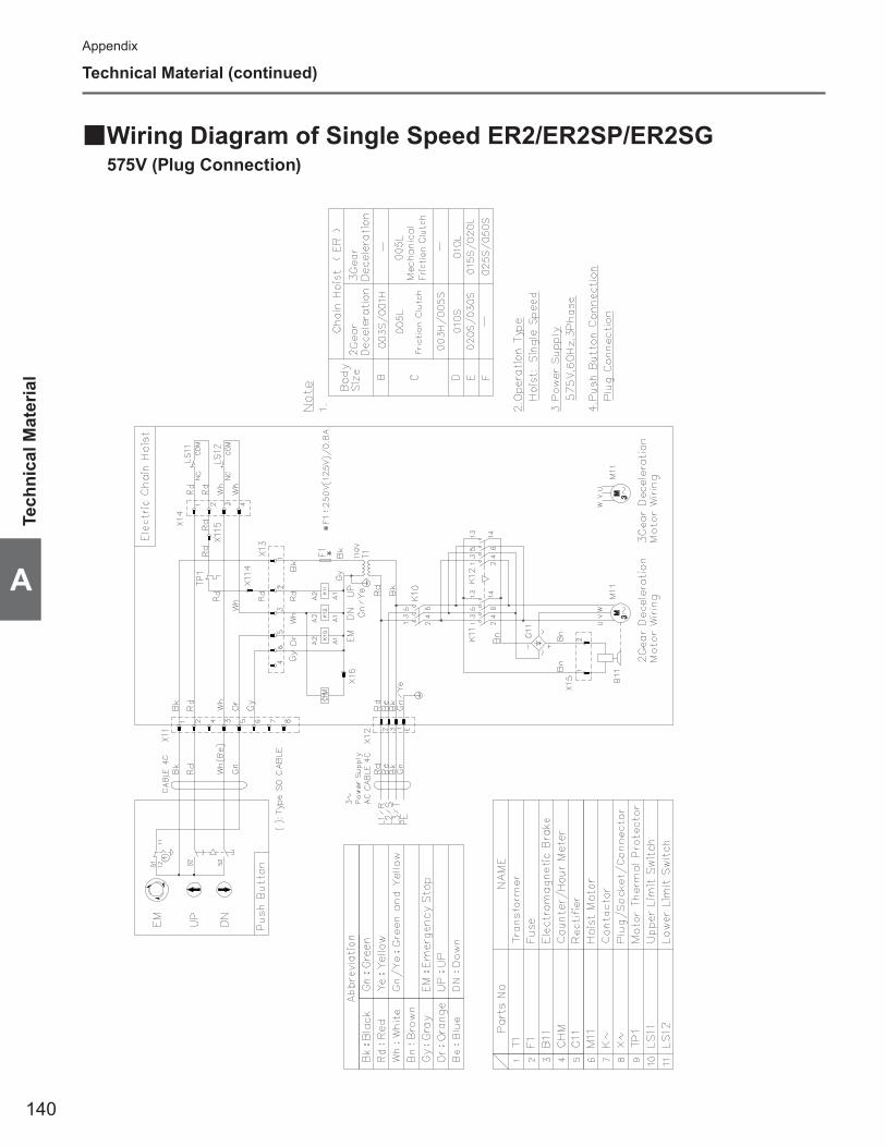
140
Appendix
A
Technical Material (continued)
Wiring Diagram of Single Speed ER2/ER2SP/ER2SG ■575V (Plug Connection)
Tech
nica
l Mat
eria
l
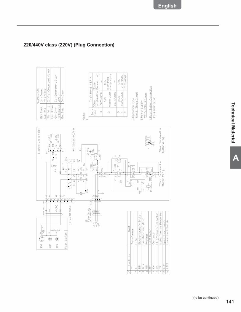
141
A
(to be continued)
Technical Material
220/440V class (220V) (Plug Connection)
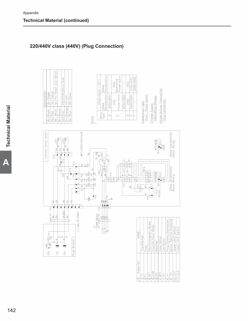
142
Appendix
A
Technical Material (continued)
Tech
nica
l Mat
eria
l
220/440V class (440V) (Plug Connection)
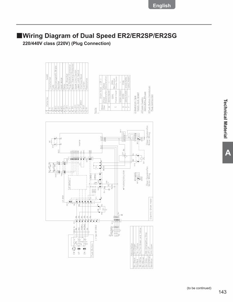
143
A
(to be continued)
Technical Material
Wiring Diagram of Dual Speed ER2/ER2SP/ER2SG ■220/440V class (220V) (Plug Connection)

144
Appendix
A
Technical Material (continued)
Tech
nica
l Mat
eria
l
220/440V class (440V) (Plug Connection)

145
A
(to be continued)
Technical Material
575V class (Plug Connection)
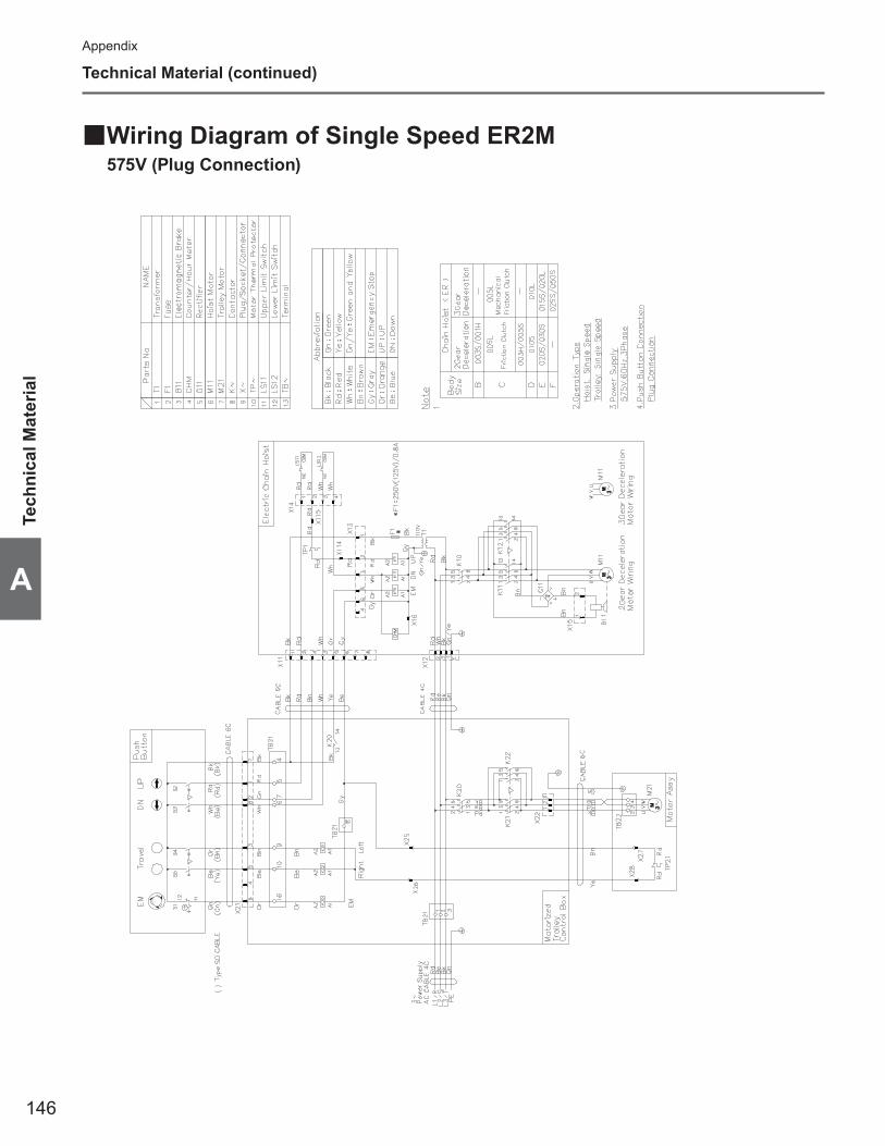
146
Appendix
A
Technical Material (continued)
Tech
nica
l Mat
eria
l
Wiring Diagram of Single Speed ER2M ■575V (Plug Connection)
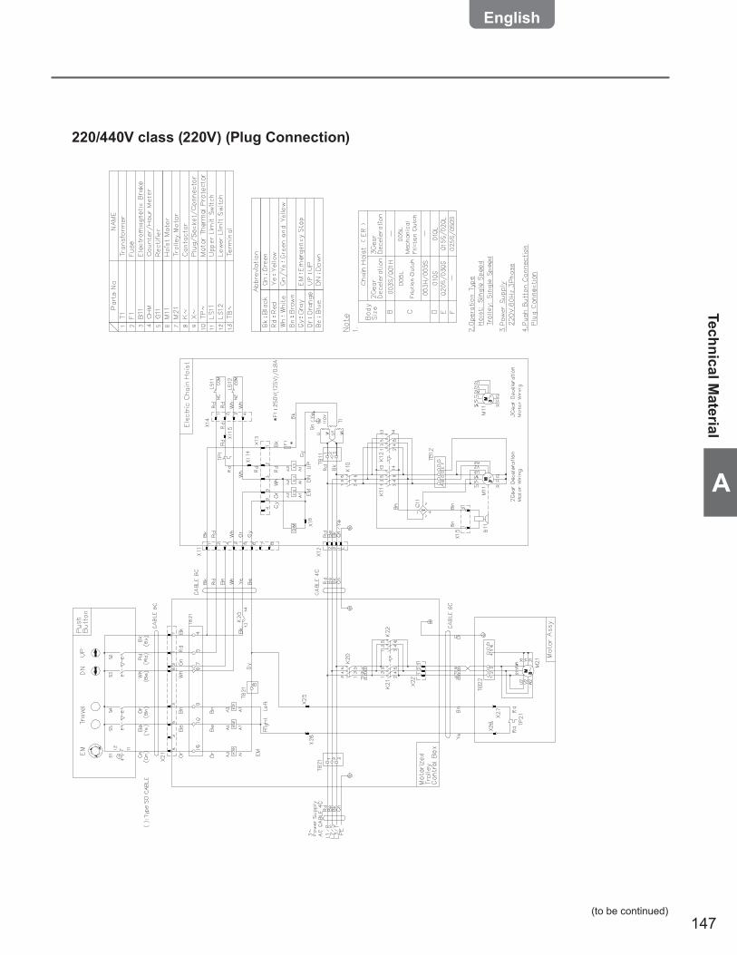
147
A
(to be continued)
Technical Material
220/440V class (220V) (Plug Connection)
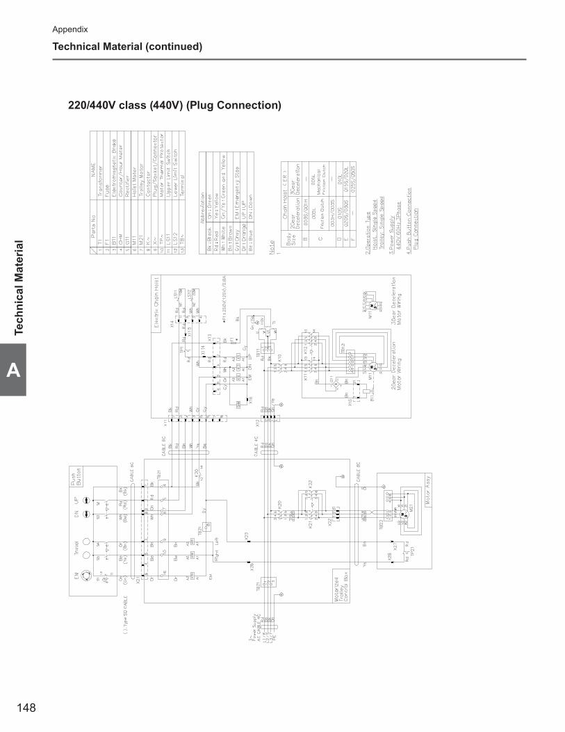
148
Appendix
A
Technical Material (continued)
Tech
nica
l Mat
eria
l
220/440V class (440V) (Plug Connection)
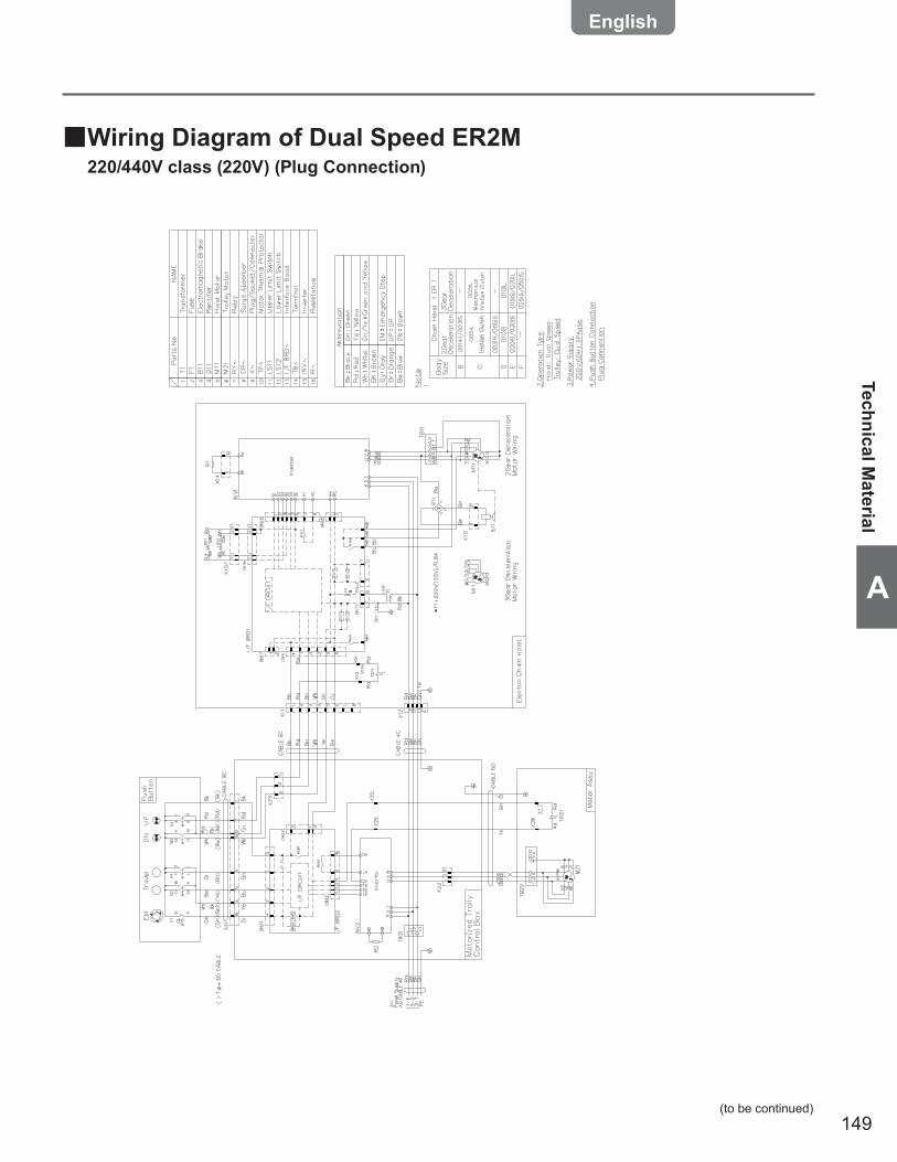
149
A
(to be continued)
Technical Material
Wiring Diagram of Dual Speed ER2M ■220/440V class (220V) (Plug Connection)
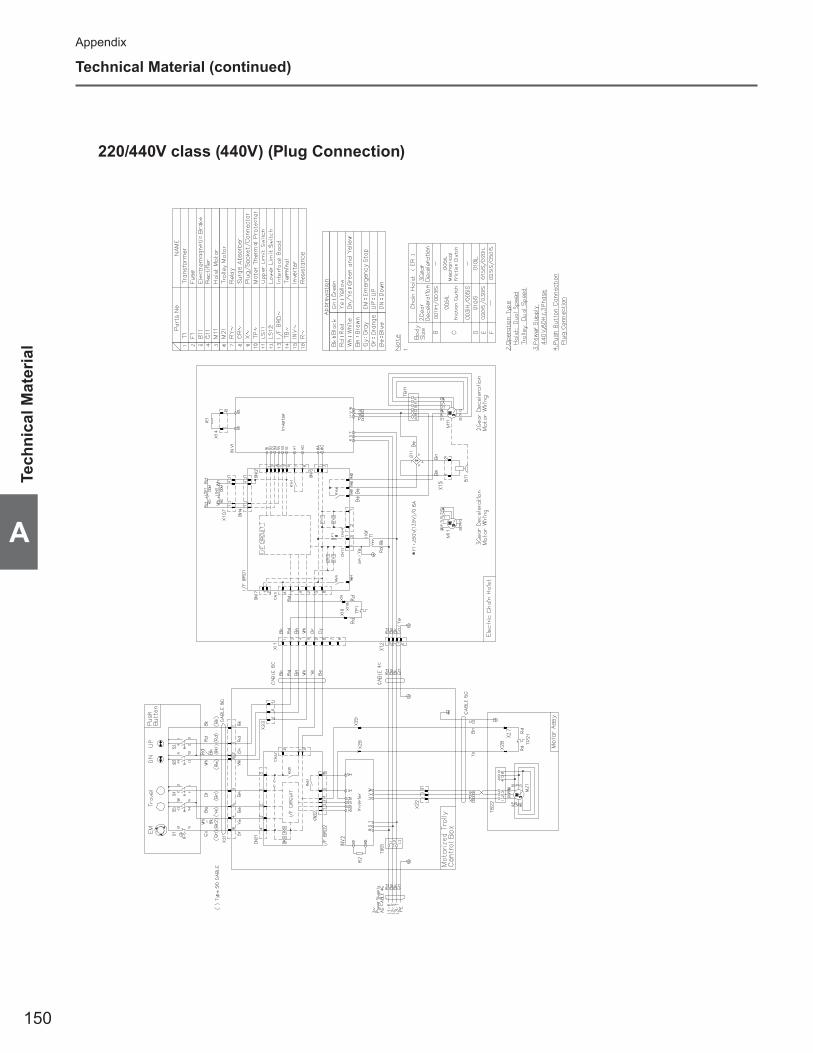
150
Appendix
A
Technical Material (continued)
Tech
nica
l Mat
eria
l
220/440V class (440V) (Plug Connection)

151
A
Technical Material
575V class (Plug Connection)

152
Appendix
A
Check Sheet for ER2 Series Electric Chain Hoist Daily Inspection
Electric Chain Hoist ER2 Daily Inspection ■Check result : ■ ○ Good, △To be replaced (adjusted) next inspection, ×Bad, Needs replacement (adjustment)
Category Check item Check method Criteria Inspection date/result/ / / / / /
Appe
aran
ce
Indication of nameplates and labels Visual inspection To have no peeled off. To be legible clearly.Deformation and damage of each part of body size Visual inspection To have no apparent deformation or corrosion
Bolts, nut, split pins Visual inspection To have no loosened bolts, nuts, and split pins that can be seen from exterior. To have no come-off.
Load
Cha
in
Elongation of pitch Visual inspection To have no apparent elongationAbrasion of wire diameter Visual inspection To have no apparent abrasionDeformation, fl aw, entanglement Visual inspection To have no apparent deformation, harmful fl aw and
entanglementRust, corrosion Visual inspection To have no apparent rust and corrosionTwist Visual inspection To have no twisting due to capsized Bottom Hook of
double typeOiling Visual inspection To be oiled adequatelyCheck of mark Visual inspection To have no error in indication and marked pitch
Top H
ook,
Botto
m Ho
ok
Stretched opening Visual inspection To have no stretched openingAbrasion Visual inspection To have no apparent abrasionDeformation, fl aw, corrosion Visual inspection To have no apparent deformation, harmful fl aw and
corrosionHook Latch motion Visual inspection/inspection
by operation To open/close smoothly
Hook motion (swivel) Visual inspection/inspection by operation
To have no apparent gap between Hook and Bottom Yoke
Idle Sheave motion Visual inspection/inspection by operation Load Chain to move smoothly
Bottom Yoke Visual inspection To have no loosened bolt and nut
Body
size
pe
riphe
ral
part Chain spring Visual inspection To have no apparent permanent set
Cushion rubber Visual inspection To have no apparent permanent set• To have no crack and peel off of rubber and steel plate•
Push
Bu
tton
Switc
h
Switch body size Visual inspection To have no deformation, damage and loosened screw• Indication to be legible clearly•
Func
tion/p
erfor
manc
e
Operational checkPress the push buttons to check the operation
Load Chain to be wound smoothly• Electric Chain Hoist operates in the same direction as that • of the push button operation Motor to stop immediately when stopping the operation• All operations to stop when Emergency Stop is pressed• Electric Chain Hoist not to operate when pressing the push • button while Emergency Stop is pressed Electric Chain Hoist to operate normally when canceling • Emergency Stop
Brake Lifting/lowering operation with no load
Brake to operate securely and Bottom Hook to stop immediately (Guideline: Travel of the load chain is within 2 to 3 links.)
Friction Clutch with Mechanical Brake
Lifting/lowering operation with no load To sound clicking noise of pawl when lifting
Limit switch Lifting/lowering operation with no load
Motor to stop automatically when operating the electric chain hoist to upper/lower limit
Strange noise Lifting/lowering operation with no load To have no strange sound or vibration
Executed by InspectorChecked by Maintenance Engineer
Code Capacity Lot No. Your CTRL No. Installation date Location Inspection Certification valid thruElectric Chain Hoist ER2Motorized Trolley MR2Geared Trolley TS2 (TSG)Plain Trolley TS2 (TSP)
Chec
k Sh
eet f
or E
R2 S
erie
s El
ectri
c Ch
ain
Hois
t Dai
ly in
spec
tion
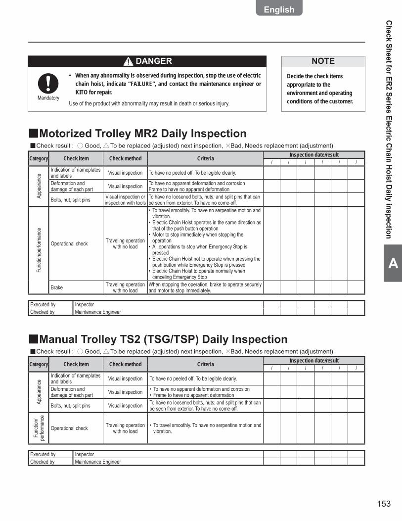
153
A
When any abnormality is observed during inspection, stop the use of electric •chain hoist, indicate “FAILURE”, and contact the maintenance engineer or KITO for repair.
Use of the product with abnormality may result in death or serious injury.Mandatory
Decide the check items appropriate to the environment and operating conditions of the customer.
NOTE
Check Sheet for ER2 Series Electric Chain Hoist Daily inspection
Motorized Trolley MR2 Daily Inspection ■Check result : ■ ○ Good, △To be replaced (adjusted) next inspection, ×Bad, Needs replacement (adjustment)
Category Check item Check method Criteria Inspection date/result/ / / / / /
Appe
aran
ce
Indication of nameplates and labels Visual inspection To have no peeled off. To be legible clearly.
Deformation and damage of each part Visual inspection To have no apparent deformation and corrosion
Frame to have no apparent deformation
Bolts, nut, split pins Visual inspection or inspection with tools
To have no loosened bolts, nuts, and split pins that can be seen from exterior. To have no come-off.
Func
tion/p
erfor
manc
e
Operational check Traveling operation with no load
To travel smoothly. To have no serpentine motion and • vibration. Electric Chain Hoist operates in the same direction as • that of the push button operation Motor to stop immediately when stopping the • operation All operations to stop when Emergency Stop is • pressed Electric Chain Hoist not to operate when pressing the • push button while Emergency Stop is pressed Electric Chain Hoist to operate normally when • canceling Emergency Stop
Brake Traveling operation with no load
When stopping the operation, brake to operate securely and motor to stop immediately.
Executed by InspectorChecked by Maintenance Engineer
Manual Trolley TS2 (TSG/TSP) Daily Inspection ■Check result : ■ ○ Good, △To be replaced (adjusted) next inspection, ×Bad, Needs replacement (adjustment)
Category Check item Check method Criteria Inspection date/result/ / / / / /
Appe
aran
ce
Indication of nameplates and labels Visual inspection To have no peeled off. To be legible clearly.
Deformation and damage of each part Visual inspection To have no apparent deformation and corrosion•
Frame to have no apparent deformation•
Bolts, nut, split pins Visual inspection To have no loosened bolts, nuts, and split pins that can be seen from exterior. To have no come-off.
Func
tion/
perfo
rman
ce
Operational check Traveling operation with no load
To travel smoothly. To have no serpentine motion and • vibration.
Executed by InspectorChecked by Maintenance Engineer
DANGER

154
Appendix
A
Check Sheet for ER2 Series Electric Chain Hoist Frequent Inspection
Electric Chain Hoist ER2 Frequent Inspection ■Check result : ■ ○ Good, △To be replaced (adjusted) next inspection, ×Bad, Needs replacement (adjustment)
Category Check item Check method Criteria Inspection date/result/ / / / / /
Prec
eding
ins
pecti
on
Daily inspection Check the execution When performing frequent inspection, also perform the daily inspection.
Load
Cha
in Elongation of pitch Pitch measurement Sum of pitches for 5 links must not exceed the limit value.
Abrasion of wire diameter
Diameter measurement Not to exceed the limit value
Top H
ook,
Botto
m Ho
ok Stretched opening Measurement Interval between embossed marks not to exceed the limit value
Abrasion Measurement To have no abrasion exceeding the limit value (5 %)Deformation, fl aw, corrosion Visual inspection To have no bending and twist•
To have no attached foreign matter such as sputter•
Body
size
pe
riphe
ral
part Chain container Visual inspection
To be mounted securely• To have no breakage, deformation and foreign matter• Lift must be shorter than the length of the permissible • capacity of the chain container
Elec
troma
gneti
c br
ake
Number of start Check CH Meter Gap not to exceed the limit value (estimate the time to arrive at one million times)
Push
Butt
on S
witch Switch body size
Visual inspection/inspection by
operation
Operation buttons to move smoothly• Emergency Stop button to be enabled to operate and • cancel
Push Button Switch cord Visual inspectionTo be tied securely• Protection wire to prevent external force to be applied • on the cord when being pulledTo have no damage•
Powe
r fee
ding Power cable Visual inspection
To have slack• To have no damage• To be connected securely•
Cable hanger Visual inspectionTo have no damage• To move with a small force• To be mounted at equal spacing•
Messenger wire Visual inspection To have no slack•
Func
tion/
perfo
rman
ce
Strange noiseLifting/lowering
operation with no load
To have no humming noise from motor and scraping • sound of the brake To have no popping sound of load chain from the • chain guide
Executed by InspectorChecked by Maintenance Engineer
Chec
k Sh
eet f
or E
R2 S
erie
s El
ectri
c Ch
ain
Hois
t Fre
quen
t Ins
pect
ion
Code Capacity Lot No. Your CTRL No. Installation date Location Inspection Certification valid thruElectric Chain Hoist ER2Motorized Trolley MR2Geared Trolley TS2 (TSG)Plain Trolley TS2 (TSP)

155
A
Check Sheet for ER2 Series Electric Chain Hoist Frequent Inspection
Motorized Trolley MR2 Frequent Inspection ■Check result : ■ ○ Good, △To be replaced (adjusted) next inspection, ×Bad, Needs replacement (adjustment)
Category Check item Check method Criteria Inspection date/result/ / / / / /
Prec
eding
ins
pecti
on
Daily inspection Check the execution
When performing frequent inspection, also perform the daily inspection.
Appe
aran
ce Combination Shake the hoist Electric chain hoist to swing right and left swiftlyTravel rail (guider) Visual inspection To have apparent deformation and damageOiling Visual inspection To be oiled adequately
Refer to check table of electric chain hoist ER2 for electrical parts, push button switch, power feeding and electrical characteristics.
Executed by InspectorChecked by Maintenance Engineer
Manual Trolley TS2 (TSG/TSP) Frequent Inspection ■Check result : ■ ○ Good, △To be replaced (adjusted) next inspection, ×Bad, Needs replacement (adjustment)
Category Check item Check method Criteria Inspection date/result/ / / / / /
Appe
aran
ce Combination Shake the hoist Electric chain hoist to swing right and left swiftlyTravel rail (guider) Visual inspection To have apparent deformation and damageOiling Visual inspection To be oiled adequately
Executed by InspectorChecked by Maintenance Engineer
When any abnormality is observed during inspection, stop the use of electric •chain hoist, indicate “FAILURE”, and contact the maintenance engineer or KITO for repair.
Use of the product with abnormality may result in death or serious injury.
DANGER
Mandatory
Decide the check items appropriate to the environment and operating conditions of the customer.
NOTE

156
Appendix
A
Check Sheet for ER2 Series Electric Chain Hoist Periodic Inspection
Electric Chain Hoist ER2 Periodic Inspection (1/2) ■Check result : ■ ○ Good, △To be replaced (adjusted) next inspection, ×Bad, Needs replacement (adjustment)
Category Check item Check method Criteria Inspection date/result/ / / / / /
Prec
eding
ins
pecti
on Daily inspection Check the execution When performing periodic inspection, also perform the daily inspection.
Frequent inspection Check the execution When performing periodic inspection, also perform the frequent inspection.
Top H
ook,
Botto
m Ho
ok Number of start Check CH Meter Number of start not to exceed the guidelines for replacement
Body
size
perip
hera
l par
t
Chain guide A Visual inspection To have no apparent abrasion and damage• To have no fl aw due to hitting by Load Chain•
Chain springVisual inspection/
inspection by measurement
To have no apparent permanent setting (deformation)• Length of the chain spring to be longer than the • criteria
Stopper Visual inspection Stopper must be mounted securely at the third link from the load chain end at no load side
Limit leverVisual inspection/
inspection by operation
To have no deformation, damage and abrasion• To move smoothly• To be clean•
Chain pinVisual inspection/
inspection by measurement
To have no apparent deformation and fl aw• Not to lower the criteria•
Connection YokeVisual inspection/
inspection by measurement
To have no apparent deformation, abrasion and • damage The difference between the hole diameter in vertical • and lateral to be within 0.5 mm
Shaft retainer clip Visual inspection To have no deformation, damage and abrasion• To be mounted securely without looseness•
Oil
Oil leakage Visual inspection To have no oil leakage at packing, oil seal and oil plug
Oil amount and stain Visual inspectionOil is fi lled enough close to the oil check hole.• Gear oil has viscosity but not stained.• Check the operating hours with CH Meter. Operating • hours not to exceed the guidelines for oil change.
Elec
troma
gneti
c bra
ke
Appearance Visual inspection To have no loosened bolts and screws• To have no fl aw and damage•
Gap Measurement The gap not to exceed the limit value
Hub and joint Visual inspection To have no deformation and abrasion• Hub spring not to come off•
Number of start Check the CH Meter
Check the gap at the number of start arrives at one million times. Check the gap regularly after that and replace the electromagnetic brake when the gap arrives at the limit gap or the number of start arrives at two million times.
Chec
k Sh
eet f
or E
R2 S
erie
s El
ectri
c Ch
ain
Hois
t Per
iodi
c In
spec
tion
Code Capacity Lot No. Your CTRL No. Installation date Location Inspection Certification valid thruElectric Chain Hoist ER2Motorized Trolley MR2Geared Trolley TS2 (TSG)Plain Trolley TS2 (TSP)
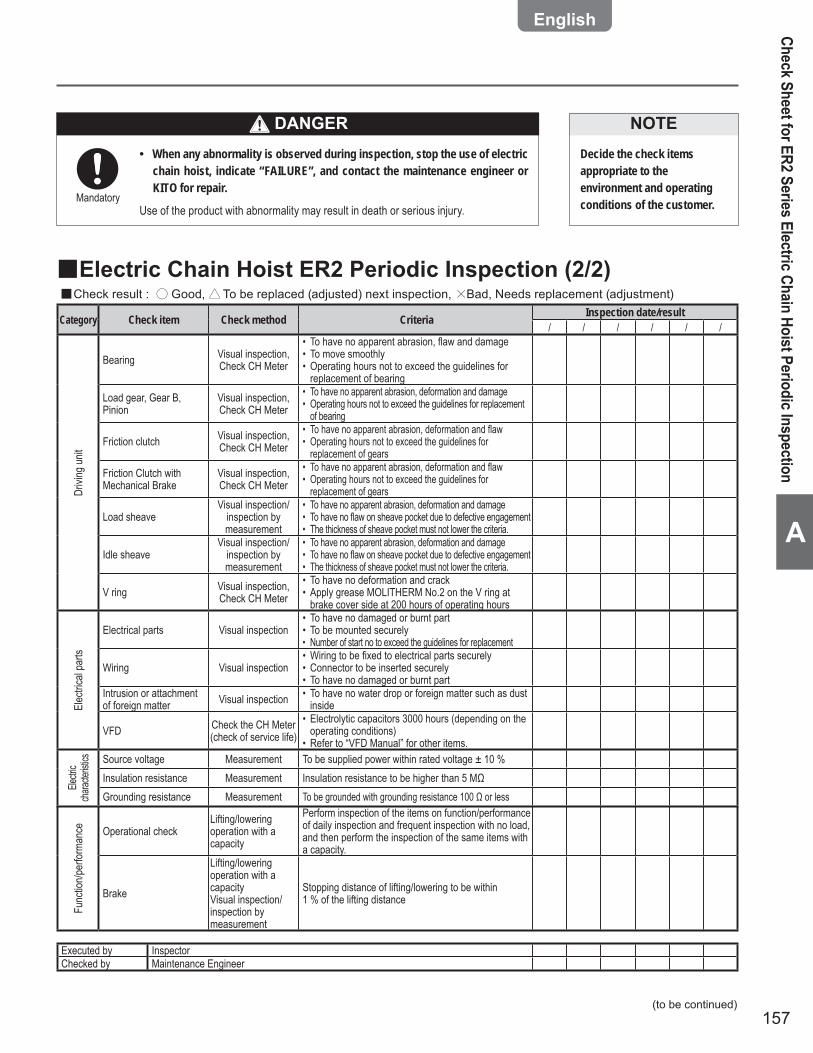
157
A
Electric Chain Hoist ER2 Periodic Inspection (2/2) ■Check result : ■ ○ Good, △To be replaced (adjusted) next inspection, ×Bad, Needs replacement (adjustment)
Category Check item Check method Criteria Inspection date/result/ / / / / /
Drivi
ng un
it
Bearing Visual inspection, Check CH Meter
To have no apparent abrasion, fl aw and damage• To move smoothly• Operating hours not to exceed the guidelines for • replacement of bearing
Load gear, Gear B, Pinion
Visual inspection, Check CH Meter
To have no apparent abrasion, deformation and damage• Operating hours not to exceed the guidelines for replacement • of bearing
Friction clutch Visual inspection, Check CH Meter
To have no apparent abrasion, deformation and fl aw• Operating hours not to exceed the guidelines for • replacement of gears
Friction Clutch with Mechanical Brake
Visual inspection, Check CH Meter
To have no apparent abrasion, deformation and fl aw• Operating hours not to exceed the guidelines for • replacement of gears
Load sheaveVisual inspection/
inspection by measurement
To have no apparent abrasion, deformation and damage• To have no fl aw on sheave pocket due to defective engagement• The thickness of sheave pocket must not lower the criteria.•
Idle sheaveVisual inspection/
inspection by measurement
To have no apparent abrasion, deformation and damage• To have no fl aw on sheave pocket due to defective engagement• • The thickness of sheave pocket must not lower the criteria.
V ring Visual inspection, Check CH Meter
To have no deformation and crack• Apply grease MOLITHERM No.2 on the V ring at • brake cover side at 200 hours of operating hours
Elec
trical
parts
Electrical parts Visual inspectionTo have no damaged or burnt part• To be mounted securely• Number of start no to exceed the guidelines for replacement•
Wiring Visual inspectionWiring to be fi xed to electrical parts securely• Connector to be inserted securely• To have no damaged or burnt part•
Intrusion or attachment of foreign matter Visual inspection To have no water drop or foreign matter such as dust •
inside
VFD Check the CH Meter (check of service life)
Electrolytic capacitors 3000 hours (depending on the • operating conditions)Refer to “VFD Manual” for other items.•
Electr
ic ch
aracte
ristics Source voltage Measurement To be supplied power within rated voltage ± 10 %
Insulation resistance Measurement Insulation resistance to be higher than 5 MΩGrounding resistance Measurement To be grounded with grounding resistance 100 Ω or less
Func
tion/p
erfor
manc
e Operational checkLifting/lowering operation with a capacity
Perform inspection of the items on function/performance of daily inspection and frequent inspection with no load, and then perform the inspection of the same items with a capacity.
Brake
Lifting/lowering operation with a capacityVisual inspection/inspection by measurement
Stopping distance of lifting/lowering to be within 1 % of the lifting distance
Executed by InspectorChecked by Maintenance Engineer
(to be continued)
Check Sheet for ER2 Series Electric Chain Hoist Periodic Inspection
When any abnormality is observed during inspection, stop the use of electric •chain hoist, indicate “FAILURE”, and contact the maintenance engineer or KITO for repair.
Use of the product with abnormality may result in death or serious injury.Mandatory
Decide the check items appropriate to the environment and operating conditions of the customer.
NOTEDANGER

158
Appendix
A
Check Sheet for ER2 Series Electric Chain Hoist Periodic Inspection (continued)
Motorized Trolley MR2 Periodic Inspection ■Check result : ■ ○ Good, △To be replaced (adjusted) next inspection, ×Bad, Needs replacement (adjustment)
Category Check item Check method Criteria Inspection date/result/ / / / / /
Prec
eding
ins
pecti
on Daily inspection Check the execution When performing periodic inspection, also perform the daily inspection.
Frequent inspection Check the execution When performing periodic inspection, also perform the frequent inspection.
Brak
e Appearance Visual inspection To have no deformation, fl aw and damage on the • brake drum and motor cover To have no deformation, fl aw and damage on • brake spring
Brake Pad Measurement Abrasion to be less than limit value
Body
size
comp
onen
t
WheelVisual inspection/
inspection by measurement
To have apparent deformation and damage• Abrasion of outer diameter to be less than limit • value
Side rollerVisual inspection/
inspection by measurement
To have no apparent deformation and damage• Abrasion of outer diameter to be less than limit • value
Lifting shaftVisual inspection/
inspection by measurement
To have no apparent deformation and damage• Abrasion of outer diameter to be less than limit • value
SuspenderVisual inspection/
inspection by measurement
To have no apparent deformation and damage• Abrasion of outer diameter to be less than limit • value
Gear frame packing Visual inspection To have no damage, breakage and grease leakage.• Gears, motor shaft Visual inspection To have no apparent abrasion, deformation and damage•
Trav
el Ra
il
Rail surface Visual inspection To have no attachment of paint, oil and foreign matter• To have no dust and powder due to abrasion•
Deformation, abrasion Visual inspection/
inspection by measurement
To have no deformation of beam fl ange such as • twist and shear dropTo have no exceeding abrasion of rail surface•
Rail fi xing bolt Visual inspection To be mounted securely without looseness and come-off
Stopper Visual inspection To be mounted securely without looseness and come-off at the rail end
Relay
ca
ble Appearance Visual inspection To be connected securely without deformation and damage
Refer to check table of electric chain hoist ER2 for electrical parts, push button switch, power feeding and electrical characteristics.
Func
tion/p
erfor
manc
e Operational checkTraveling operation with a capacityVisual inspection/inspection by measurement
Perform inspection of the items on function/performance of daily inspection with no load, and then perform the inspection of the same items with a capacity.
To travel smoothly without serpentine motion and • vibration
BrakeTraveling operation with a capacityVisual inspection/inspection by measurement
Stopping distance of traveling to be within 10 % • of the traveling distance, when no swinging of a load
Strange noiseTraveling operation with a capacityVisual inspection/inspection by measurement
To have no irregular rotating noise• To have no motor hamming or scraping noise of a • brake
Executed by InspectorChecked by Maintenance Engineer
Chec
k She
et fo
r ER2
Ser
ies E
lectri
c Cha
in H
oist
Per
iodi
c Ins
pect
ion
Code Capacity Lot No. Your CTRL No. Installation date Location Inspection Certification valid thruElectric Chain Hoist ER2Motorized Trolley MR2Geared Trolley TS2 (TSG)Plain Trolley TS2 (TSP)

159
A
Manual Trolley TS2 (TSG/TSP) Periodic Inspection ■Check result : ■ ○ Good, △To be replaced (adjusted) next inspection, ×Bad, Needs replacement (adjustment)
Category Check item Check method Criteria Inspection date/result/ / / / / /
Body
size
comp
onen
t WheelVisual inspection/
inspection by measurement
To have no apparent deformation and damage• Abrasion of outer diameter to be less than limit • value
Lifting shaftVisual inspection/
inspection by measurement
To have no apparent deformation and damage• Abrasion of outer diameter to be less than limit • value
SuspenderVisual inspection/
inspection by measurement
To have no apparent deformation and damage• Abrasion of outer diameter to be less than limit • value
Trav
el ra
il
Rail surface Visual inspection To have no attachment of paint, oil and foreign • matterTo have no dust and powder due to abrasion•
Deformation, abrasionVisual inspection/
inspection by measurement
To have no deformation of beam fl ange such as • twist and shear dropTo have no exceeding abrasion of rail surface•
Rail fi xing bolt Visual inspection To be mounted securely without looseness and come-off
Stopper Visual inspection To be mounted securely without looseness and come-off at the rail end
Func
tion/p
erfor
manc
e
Operational check
Traveling operation with a capacityVisual inspection/inspection by measurement
Perform inspection of the items on function/performance of daily inspection with no load, and then perform the inspection of the same items with a capacity.
Strange noise
Traveling operation with a capacityVisual inspection/inspection by measurement
Perform inspection of the items on function/performance of daily inspection with no load, and then perform the inspection of the same items with a capacity.
Executed by InspectorChecked by Maintenance Engineer
When any abnormality is observed during inspection, stop the use of electric •chain hoist, indicate “FAILURE”, and contact the maintenance engineer or KITO for repair.
Use of the product with abnormality may result in death or serious injury.Mandatory
Decide the check items appropriate to the environment and operating conditions of the customer.
NOTE
Check Sheet for ER2 Series Electric Chain Hoist Periodic Inspection
DANGER
160
W
WA
RR
AN
TY
WARRANTYKITO Corporation (“KITO”) extends the following warranty to the original purchaser (“Purchaser”) of new products manufactured by KITO (KITO’s Products).
1) KITO warrants that KITO's Products, when shipped, shall be free from defects in workmanship and/or materials under normal use and service and KITO shall, at the election of KITO, repair or replace free of charge any parts or items which are proven to have said defects, provided that all claims for defects under this warranty shall be made in writing immediately upon discovery and, if there is anything within a warranty period stated by your dealer from whom you purchased the products from the date of purchase of KITO's Products by Purchaser and provided, further, that defective parts or items shall be kept for examination by KITO or its authorized agents or returned to KITO's factory or authorized service center upon request by KITO.
2) KITO does not warrant components of products provided by other manufacturers. However to the extent possible, KITO will assign to Purchaser applicable warranties of such other manufacturers.
3) Except for the repair or replacement mentioned in (1) above which is KITO's sole liability and purchaser’s exclusive remedy under this warranty, KITO shall not be responsible for any other claims arising out of the purchase and use of KITO’s Products, regardless of whether Purchaser’s claims are based on breach of contract, tort or other theories, including claims for any damages whether direct, incidental or consequential.
4) This warranty is conditional upon the installation, maintenance and use of KITO’s Products pursuant to the product manuals prepared in accordance with content instructions by KITO. This warranty shall not apply to KITO’s Products which have been subject to negligence, misuse, abuse, misapplication or any improper use or combination or improper fittings, alignment or maintenance.
5) KITO shall not be responsible for any loss or damage caused by transportation, prolonged or improper storage or normal wear and tear of KITO’s Products for loss of operating time.
6) This warranty shall not apply to KITO’s Products which have been fitted with or repaired with parts, components or items not supplied or approved by KITO or which have been modified or altered.
THIS WARRANTY IS IN LIEU OF ALL OTHER WARRANTIES. EXPRESS OR IMPLIED, INCLUDING BUT NOT LIMITED TO ANY WARRANTY OF MERCHANTABILITY OR OF FITNESS FOR A PARTICULAR PURPOSE.