Embed Size (px)
Citation preview
EQJW 135: Heating controller for boiler control systems,equitherm
How energy efficiency is improvedWeather-dependent control of the boiler temperature and integrated automatic cut-off for the heatingto save energy
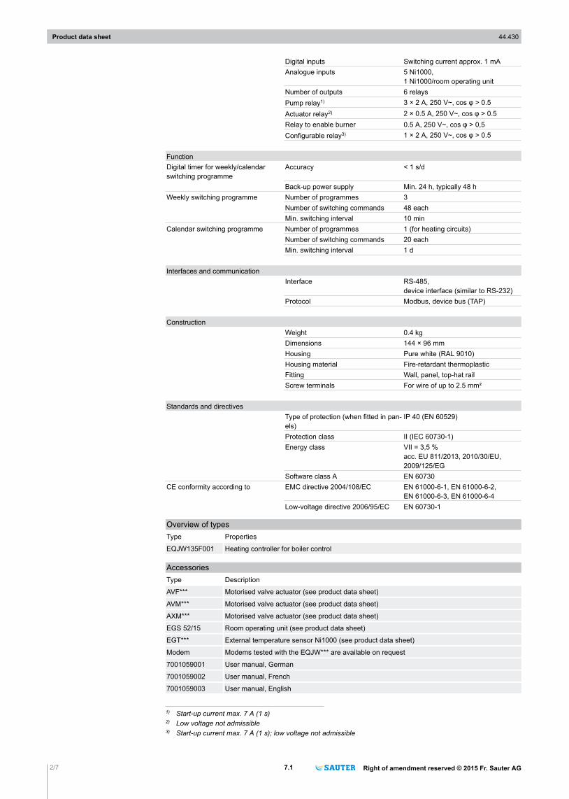
Features• Weather-dependent boiler- and/or supply-temperature control, and drinking water circuit in buildings
of all kinds• Convenient to use with modern operating concept (turn and press) and large LCD• Communication via Modbus RTU or proprietary device bus• Convenient weekly and calendar switching programmes with optimisation of switching times• Automatic summertime/wintertime changeover• Limitation of boiler temperature and function for boiler start-up relief• Min./max. limitation of supply temperature and maintenance of return temperature• Frost-protection facility and anti-jamming function for valve• Screed curing (floor-drying functions)• Function for protecting against legionellae• Connection of room temperature via room-temperature sensor or room operating unit• Ni1000 inputs for the outside, supply, boiler, DHW, return and room temperatures or for room oper-
ating unit• Relay output for activating control units and pumps and for enabling burner levels, additional multi-
functional relay output• Manual mode• Logbook• Notification by text message• Electrical connection in baseplate
Technical data
Power supplyPower supply 230 V~, ±15%, 50...60 HzPower consumption Approx. 1 VA
ParametersControl characteristic Boiler temperature 2-point
Supply temperature PI controlDomestic-hot-water temperature 2-point
Control parameters Proportional band 2...100 KIntegral action time 15...1000 sSwitching difference, boiler 1...9 KSwitching difference, domestic hotwater
1...19 K
Frost-protection temperature 3 °CTemperature ranges Normal temperature 0...40 °C
Reduced temperature 0...40 °CSupply temperature 0...130 °CReturn temperature 0...130 °CBoiler temperature 0...130 °COutside temperature –50...50 °CDomestic-hot-water temperature 20...90 °CRunning time of valve 30...300 sCycle time Running time of the valve ÷ 15
Ambient conditionsAdmissible ambient temperature 0...50 °CAdmissible humidity 5...95% rh, no condensationStorage and transport temperature –25...65 °C
Inputs/OutputsNumber of inputs 1 digital, 6 analogue
Product data sheet 44.430
Right of amendment reserved © 2015 Fr. Sauter AG 7.1 1/7
EQJW135F001
Digital inputs Switching current approx. 1 mAAnalogue inputs 5 Ni1000,
1 Ni1000/room operating unitNumber of outputs 6 relaysPump relay1) 3 × 2 A, 250 V~, cos φ > 0.5Actuator relay2) 2 × 0.5 A, 250 V~, cos φ > 0.5Relay to enable burner 0.5 A, 250 V~, cos φ > 0,5Configurable relay3) 1 × 2 A, 250 V~, cos φ > 0.5
FunctionDigital timer for weekly/calendarswitching programme
Accuracy < 1 s/d
Back-up power supply Min. 24 h, typically 48 hWeekly switching programme Number of programmes 3
Number of switching commands 48 eachMin. switching interval 10 min
Calendar switching programme Number of programmes 1 (for heating circuits)Number of switching commands 20 eachMin. switching interval 1 d
Interfaces and communicationInterface RS-485,
device interface (similar to RS-232)Protocol Modbus, device bus (TAP)
ConstructionWeight 0.4 kgDimensions 144 × 96 mmHousing Pure white (RAL 9010)Housing material Fire-retardant thermoplasticFitting Wall, panel, top-hat railScrew terminals For wire of up to 2.5 mm²
Standards and directivesType of protection (when fitted in pan-els)
IP 40 (EN 60529)
Protection class II (IEC 60730-1)Energy class VII = 3,5 %
acc. EU 811/2013, 2010/30/EU,2009/125/EG
Software class A EN 60730CE conformity according to EMC directive 2004/108/EC EN 61000-6-1, EN 61000-6-2,
EN 61000-6-3, EN 61000-6-4Low-voltage directive 2006/95/EC EN 60730-1
Overview of typesType Properties
EQJW135F001 Heating controller for boiler control
AccessoriesType Description
AVF*** Motorised valve actuator (see product data sheet)
AVM*** Motorised valve actuator (see product data sheet)
AXM*** Motorised valve actuator (see product data sheet)
EGS 52/15 Room operating unit (see product data sheet)
EGT*** External temperature sensor Ni1000 (see product data sheet)
Modem Modems tested with the EQJW*** are available on request
7001059001 User manual, German
7001059002 User manual, French
7001059003 User manual, English
1) Start-up current max. 7 A (1 s)2) Low voltage not admissible3) Start-up current max. 7 A (1 s); low voltage not admissible
Product data sheet 44.430
2/7 7.1 Right of amendment reserved © 2015 Fr. Sauter AG
General description of operationThe EQJW 135 heating controller performs weather-dependent supplier-temperature control and, de-pending on the application, also domestic-hot-water control and boiler temperature control. Variouscontrol models are stored in the EQJW 135 for the different applications.The temperatures (outside and supply temperatures and, depending on the application, the boiler, re-turn, domestic hot water and room temperatures) are determined with precision sensors and digital-ised in the controller. The microprocessor in the controller uses these values to calculate the signalsfor the outputs. Using the stored control model, the calculation of the output signals is based on thespecified setpoints, along with the current actual values. Additionally, the current control offset, the setcontrol parameters and the operating mode are considered. These signals are processed further viaswitching amplifiers. The results are the ON/OFF commands of the relay outputs for the control unit,the pumps and the burner.The room is supplied with the heat required to keep the room temperature constantly at the currentsetpoint. If a room-temperature sensor is connected to the EQJW 135 and parameterised, the currentroom temperature is considered in the calculation of the setpoint for the supply temperature. For thedomestic-hot-water preparation, the charge pump is activated based on the measured domestic-hot-water temperature. The output relay for enabling the burner is activated based on the heat require-ment and the current boiler temperature.The switching programmes, which the user can adapt individually, provide an optimal comfort level atthe lowest energy consumption. The temperature setpoint for the room and the domestic hot watercan be adjusted. The operating mode can be selected easily using the rotary switch. These can beused, for example, to switch off the heating or the domestic hot water for a longer period. The frost-protection facility prevents the system from freezing.The “temporary temperature change” function can be used to activate the party function or switcheasily to another operating mode for a specific period, thus saving energy. The current operating sta-tus of the system is indicated in the LCD display, where the user can see it very easily at all times.A Modbus interface is used to communicate with the controller. It is also possible to connect multiplecontrollers with each other and connect a room remote-control unit with a digital user interface. A sep-arate modem sends alarms via SMS if required.
Intended useThis product is only suitable for the purpose intended by the manufacturer, as described in the “De-scription of operation” section.All related product regulations must also be adhered to. Changing or converting the product is not ad-missible.
Engineering noteThe equitherm EQJW 135 controller must be connected to the mains power supply all year round.
AbbreviationsTA Outside temperature TI Initial point (foot point)
TF Supply temperature TR Room temperature
TRF Return temperature TB Boiler temperature
TW Domestic-hot-water temperature Xp Proportional band
Tn Integral action time SP SERVice parameters
Ty Running time of valve V Valve
UP Heating pump LP Charge pump for domestic hot waterTS/W Heating limit S Slope of heating characteristic
KW Cold water BW Domestic hot waterSymbol Factory setting q Normal mode (nominal mode based on EN 12098)
w Reduced mode a Off or back-up mode (with/without frost-protection facility)
Indexes ExampleXs Setpoint TRs Room-temperature setpoint
Xi Actual value TFi Actual value of the supply temperature
Xged Damped value TAged Damped outside temperature
max Maximum TFsmax Maximum supply setpoint
min Minimum TRsmin Minimum room setpoint
Product data sheet 44.430
Right of amendment reserved © 2015 Fr. Sauter AG 7.1 3/7
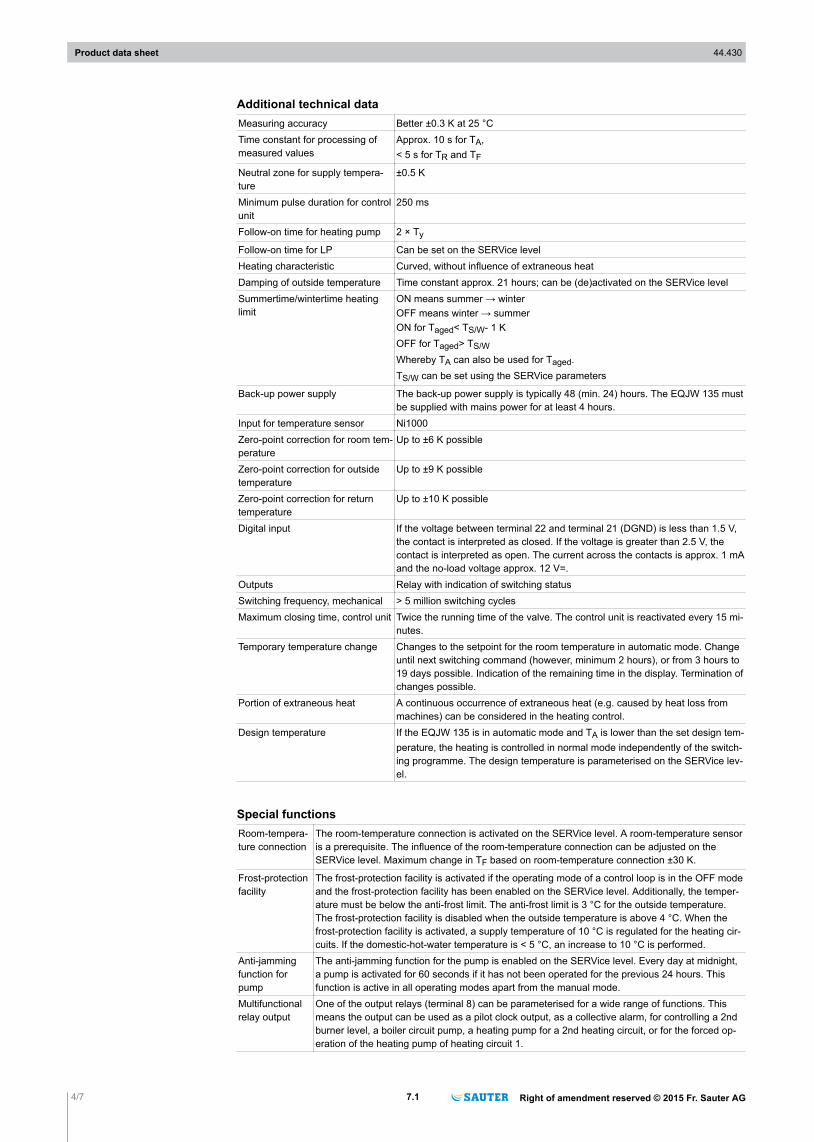
Additional technical dataMeasuring accuracy Better ±0.3 K at 25 °CTime constant for processing ofmeasured values
Approx. 10 s for TA,< 5 s for TR and TF
Neutral zone for supply tempera-ture
±0.5 K
Minimum pulse duration for controlunit
250 ms
Follow-on time for heating pump 2 × Ty
Follow-on time for LP Can be set on the SERVice levelHeating characteristic Curved, without influence of extraneous heatDamping of outside temperature Time constant approx. 21 hours; can be (de)activated on the SERVice levelSummertime/wintertime heatinglimit
ON means summer → winterOFF means winter → summerON for Taged< TS/W- 1 KOFF for Taged> TS/WWhereby TA can also be used for Taged.TS/W can be set using the SERVice parameters
Back-up power supply The back-up power supply is typically 48 (min. 24) hours. The EQJW 135 mustbe supplied with mains power for at least 4 hours.
Input for temperature sensor Ni1000Zero-point correction for room tem-perature
Up to ±6 K possible
Zero-point correction for outsidetemperature
Up to ±9 K possible
Zero-point correction for returntemperature
Up to ±10 K possible
Digital input If the voltage between terminal 22 and terminal 21 (DGND) is less than 1.5 V,the contact is interpreted as closed. If the voltage is greater than 2.5 V, thecontact is interpreted as open. The current across the contacts is approx. 1 mAand the no-load voltage approx. 12 V=.
Outputs Relay with indication of switching statusSwitching frequency, mechanical > 5 million switching cyclesMaximum closing time, control unit Twice the running time of the valve. The control unit is reactivated every 15 mi-
nutes.Temporary temperature change Changes to the setpoint for the room temperature in automatic mode. Change
until next switching command (however, minimum 2 hours), or from 3 hours to19 days possible. Indication of the remaining time in the display. Termination ofchanges possible.
Portion of extraneous heat A continuous occurrence of extraneous heat (e.g. caused by heat loss frommachines) can be considered in the heating control.
Design temperature If the EQJW 135 is in automatic mode and TA is lower than the set design tem-perature, the heating is controlled in normal mode independently of the switch-ing programme. The design temperature is parameterised on the SERVice lev-el.
Special functionsRoom-tempera-ture connection
The room-temperature connection is activated on the SERVice level. A room-temperature sensoris a prerequisite. The influence of the room-temperature connection can be adjusted on theSERVice level. Maximum change in TF based on room-temperature connection ±30 K.
Frost-protectionfacility
The frost-protection facility is activated if the operating mode of a control loop is in the OFF modeand the frost-protection facility has been enabled on the SERVice level. Additionally, the temper-ature must be below the anti-frost limit. The anti-frost limit is 3 °C for the outside temperature.The frost-protection facility is disabled when the outside temperature is above 4 °C. When thefrost-protection facility is activated, a supply temperature of 10 °C is regulated for the heating cir-cuits. If the domestic-hot-water temperature is < 5 °C, an increase to 10 °C is performed.
Anti-jammingfunction forpump
The anti-jamming function for the pump is enabled on the SERVice level. Every day at midnight,a pump is activated for 60 seconds if it has not been operated for the previous 24 hours. Thisfunction is active in all operating modes apart from the manual mode.
Multifunctionalrelay output
One of the output relays (terminal 8) can be parameterised for a wide range of functions. Thismeans the output can be used as a pilot clock output, as a collective alarm, for controlling a 2ndburner level, a boiler circuit pump, a heating pump for a 2nd heating circuit, or for the forced op-eration of the heating pump of heating circuit 1.
Product data sheet 44.430
4/7 7.1 Right of amendment reserved © 2015 Fr. Sauter AG
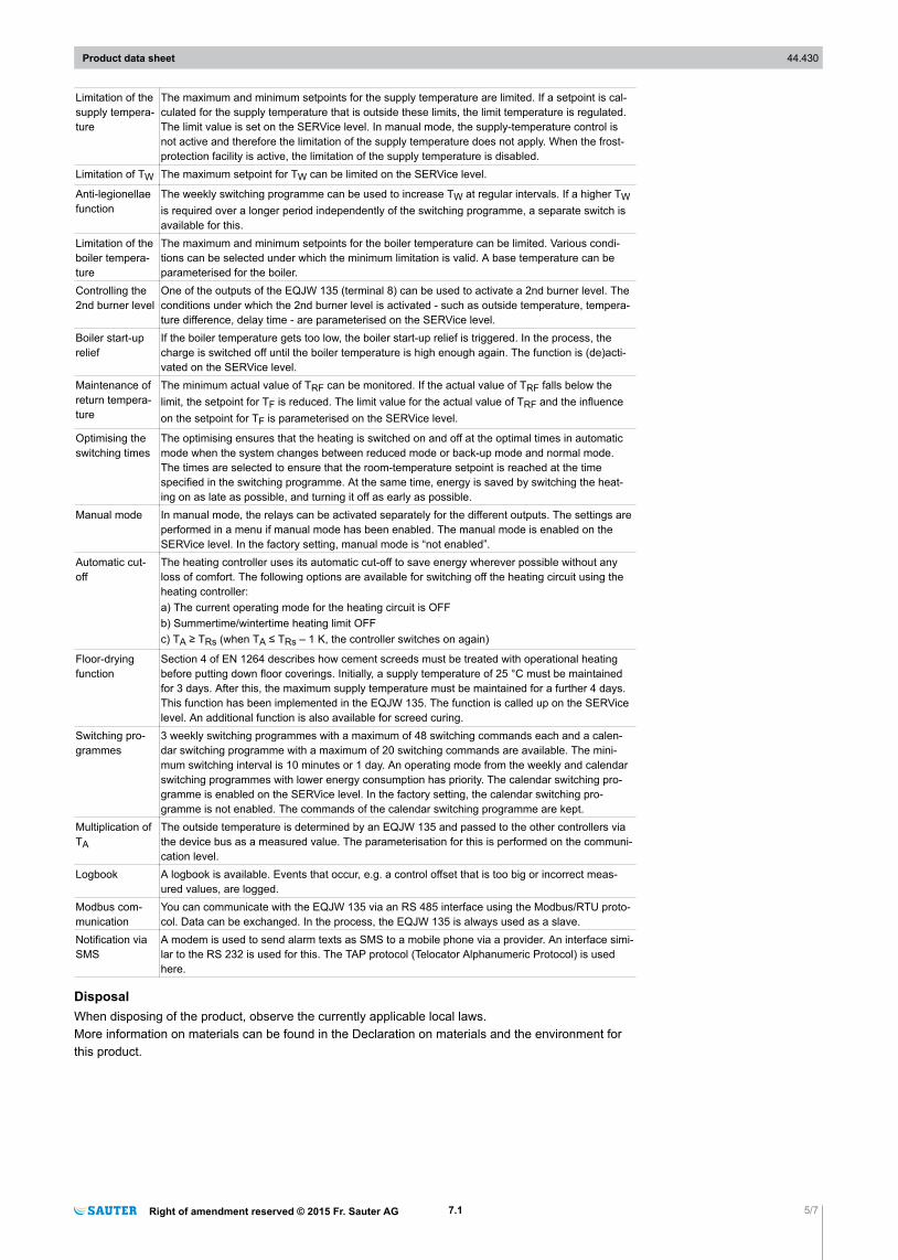
Limitation of thesupply tempera-ture
The maximum and minimum setpoints for the supply temperature are limited. If a setpoint is cal-culated for the supply temperature that is outside these limits, the limit temperature is regulated.The limit value is set on the SERVice level. In manual mode, the supply-temperature control isnot active and therefore the limitation of the supply temperature does not apply. When the frost-protection facility is active, the limitation of the supply temperature is disabled.
Limitation of TW The maximum setpoint for TW can be limited on the SERVice level.
Anti-legionellaefunction
The weekly switching programme can be used to increase TW at regular intervals. If a higher TWis required over a longer period independently of the switching programme, a separate switch isavailable for this.
Limitation of theboiler tempera-ture
The maximum and minimum setpoints for the boiler temperature can be limited. Various condi-tions can be selected under which the minimum limitation is valid. A base temperature can beparameterised for the boiler.
Controlling the2nd burner level
One of the outputs of the EQJW 135 (terminal 8) can be used to activate a 2nd burner level. Theconditions under which the 2nd burner level is activated - such as outside temperature, tempera-ture difference, delay time - are parameterised on the SERVice level.
Boiler start-uprelief
If the boiler temperature gets too low, the boiler start-up relief is triggered. In the process, thecharge is switched off until the boiler temperature is high enough again. The function is (de)acti-vated on the SERVice level.
Maintenance ofreturn tempera-ture
The minimum actual value of TRF can be monitored. If the actual value of TRF falls below thelimit, the setpoint for TF is reduced. The limit value for the actual value of TRF and the influenceon the setpoint for TF is parameterised on the SERVice level.
Optimising theswitching times
The optimising ensures that the heating is switched on and off at the optimal times in automaticmode when the system changes between reduced mode or back-up mode and normal mode.The times are selected to ensure that the room-temperature setpoint is reached at the timespecified in the switching programme. At the same time, energy is saved by switching the heat-ing on as late as possible, and turning it off as early as possible.
Manual mode In manual mode, the relays can be activated separately for the different outputs. The settings areperformed in a menu if manual mode has been enabled. The manual mode is enabled on theSERVice level. In the factory setting, manual mode is “not enabled”.
Automatic cut-off
The heating controller uses its automatic cut-off to save energy wherever possible without anyloss of comfort. The following options are available for switching off the heating circuit using theheating controller:a) The current operating mode for the heating circuit is OFFb) Summertime/wintertime heating limit OFFc) TA ≥ TRs (when TA ≤ TRs – 1 K, the controller switches on again)
Floor-dryingfunction
Section 4 of EN 1264 describes how cement screeds must be treated with operational heatingbefore putting down floor coverings. Initially, a supply temperature of 25 °C must be maintainedfor 3 days. After this, the maximum supply temperature must be maintained for a further 4 days.This function has been implemented in the EQJW 135. The function is called up on the SERVicelevel. An additional function is also available for screed curing.
Switching pro-grammes
3 weekly switching programmes with a maximum of 48 switching commands each and a calen-dar switching programme with a maximum of 20 switching commands are available. The mini-mum switching interval is 10 minutes or 1 day. An operating mode from the weekly and calendarswitching programmes with lower energy consumption has priority. The calendar switching pro-gramme is enabled on the SERVice level. In the factory setting, the calendar switching pro-gramme is not enabled. The commands of the calendar switching programme are kept.
Multiplication ofTA
The outside temperature is determined by an EQJW 135 and passed to the other controllers viathe device bus as a measured value. The parameterisation for this is performed on the communi-cation level.
Logbook A logbook is available. Events that occur, e.g. a control offset that is too big or incorrect meas-ured values, are logged.
Modbus com-munication
You can communicate with the EQJW 135 via an RS 485 interface using the Modbus/RTU proto-col. Data can be exchanged. In the process, the EQJW 135 is always used as a slave.
Notification viaSMS
A modem is used to send alarm texts as SMS to a mobile phone via a provider. An interface simi-lar to the RS 232 is used for this. The TAP protocol (Telocator Alphanumeric Protocol) is usedhere.
DisposalWhen disposing of the product, observe the currently applicable local laws.More information on materials can be found in the Declaration on materials and the environment forthis product.
Product data sheet 44.430
Right of amendment reserved © 2015 Fr. Sauter AG 7.1 5/7
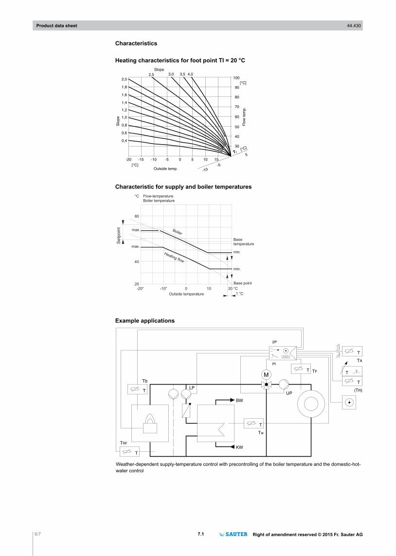
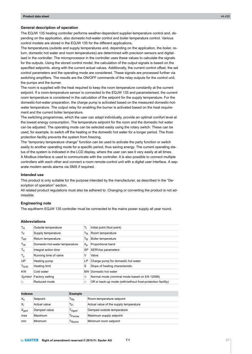
Characteristics
Heating characteristics for foot point TI = 20 °C
2,0
1,8
1,6
1,4
1,2
1,0
0,8
0,6
0,4
2,5 3,0 3,5 4,0
-20 -15 -10 -5 0 5 10 15
[°C]
100
90
80
70
60
50
40
30
-10-5
5
[°C]
T I
[°C]
Slope
Slo
pe
Outside temp.
Flo
w t
em
p.
Characteristic for supply and boiler temperatures
Basetemperature
min.
min.
Base point
-20° -10° 0 10
Heating flow
20
40
80
max.
max.
Outside temperature
20 °C
1 °C
°C Flow-temperature Boiler temperature
Boiler
Se
tpoin
t
Example applications
T
T
T
TA
(T )RUP
T TF
T
TB
T
Tw
2P
PI
M
T
LP
BW
KWTRF
Weather-dependent supply-temperature control with precontrolling of the boiler temperature and the domestic-hot-water control
Product data sheet 44.430
6/7 7.1 Right of amendment reserved © 2015 Fr. Sauter AG
2P
T
T
T
T
TA
(T )RUP
TBT
T
T
TA
(T )RUP
MT TF
T TB
T TRF
2P
PI
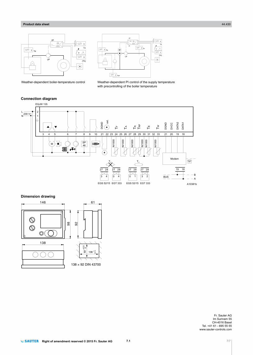
Weather-dependent boiler-temperature control Weather-dependent PI control of the supply temperaturewith precontrolling of the boiler temperature
Connection diagram
3 4 5 6 7 8
M
2
1230 V~
L
N
EQJW 135
A10381b
9 10
ext.
22 23 24 25 26 27 28 29 30 31 32 33
TF
TA
TR
TR
F
TB
TW
Ni1
00
0
Ni1
00
0
Ni1
00
0
Ni1
00
0
Ni1
00
0
Ni1
00
0
27 28
3 4
27 28
0 4
EGT 333EGS 52/15
27 28
0 1
27 28
3 2
EGT 333EGS 52/15
TR
TR
21 21
Modem
DG
ND
DV
CC
DA
TA
2
DA
TA
1
20 19 18
BUSB
A
1819
DG
ND
SP
46
Dimension drawing146
98
61
92
138
92
138+1
0
+0,5
0
138 × 92 DIN 43700
Product data sheet 44.430
Right of amendment reserved © 2015 Fr. Sauter AG 7.1 7/7
Fr. Sauter AGIm Surinam 55
CH-4016 BaselTel. +41 61 - 695 55 55
www.sauter-controls.com