Embed Size (px)
Citation preview
AAPM REPORT NO. 29
EQUIPMENT REQUIREMENTSAND QUALITY CONTROL
FOR MAMMOGRAPHYI
Published for theAmerican Association of Physicists in Medicine
by the American Institute of Physics
AAPM REPORT NO. 29
EQUIPMENT REQUIREMENTSAND QUALITY CONTROL
FOR MAMMOGRAPHY
REPORT OFTASK GROUP NO. 7
DIAGNOSTIC X-RAY IMAGING
Members
Marlin J. Yaffe (Chairman)Gary T. Barnes
Burton J. ConwayArthur G. Haus
Andrew KarellasCarolyn Kimme-Smith
Pei-Jan Paul LinGordon Mawdsley
Phillip RauchLawrence N. Rothenberg
August 1990
Published for theAmerican Association of Physicists in Medicine
by the American Institute of Physics
DISCLAIMER: This publication is based on sources andinformation believed to be reliable, but the AAPM and theeditors disclaim any warranty or liability based on or relat-ing to the contents of this publication.
The AAPM does not endorse any products, manufac-turers, or suppliers. Nothing in this publication should beinterpreted as implying such endorsement.
Further copies of this report ($10 prepaid) may be obtained from:
American Institute of Physicsc/o AIDC
64 Depot RoadColchester, Vermont 05446
(l-800-445-6638)
Library of Congress Catalog Number: 90-55637International Standard Book Number: 0-88318-807-4International Standard Serial Number: 0271-7344
© 1990 by the American Associationof Physicists in Medicine
All rights reserved. No part of this publication may be re-produced, stored in a retrieval system, or transmitted inany form or by any means (electronic, mechanical, photo-copying, recording, or otherwise) without the prior writ-ten permission of the publisher.
Published by the American Institute of Physics, Inc.335 East 45 Street, New York, NY 10017
Printed in the United States of America
EQUIPMENT REQUIREMENTS AND QUALITYCONTROL FOR MAMMOGRAPHY
1. INTRODUCTION
2. METHODS OF IMAGING
2.1 Film-Screen vs. Xeroradiography
2.1.1 Choice of X-Ray Equipment2.1.2 Differences in Patient Positioning2.1.3 Differences in Diagnostic Image Quality2.1.4 Considerations of Convenience-and Personal
Preference2.1.5 Differences in Radiation Dose
2.2 Magnification Mammography
3. FILM-SCREEN IMAGING
3.1 Selection of Equipment for Film-Screen Mammography
3.1.1 X-Ray Source Assembly3.1.2 X-ray Generator3.1.3 Geometry3.1.4 Compression Device3.1.5 Grid3.1.6 Automatic Exposure Control3.1.7 Choice of Film-Screen Combination
3.1.7.1 Film Gradient3.1.7.2 Film Speed3.1.7.3 Film-Screen Blurring3.1.7.4 Noise3.1.7.5 Higher Speed Film-Screen Combinations
3.2 Technique Selection
3 . 2 . 1 kVp3.2.2 Exposure Time
3.3 Film Processing
3.3.1 Extended Process Cycle3.3.2 Storage of Film Processing Chemicals3.3.3 Preparation of Replenishment Chemicals3.3.4 Storage of Unprocessed X-Ray Films
3.4 Viewing Conditions
- i -
3.5 Duality Control
3.5.1 Processing3.5.2 Film Density3.5.3 Image Contrast3.5.4 Entrance Skin Exposure3.5.5 Radiation Output3.5.6 Focal Spot Size3.5.7 Beam Duality - HVL3.5.8 Screens
4.1 Selection of Equipment for Xeroradiography
4.1.1 X-ray Source AssemblyTargetCapacityFocal Spot Size(s) - Contact MagnificationTube PortF i l t ra t ion
4.1.2 X-ray Generator4.1.3 Geometry4.1.4 Compression Device4.1.5 Grid4.1.6 Automatic Exposure Control
4.2 Technique Selection
4 . 2 . 1 kVp4 . 2 . 2 F i l t e r4.2.3 Beam Quality4.2.4 Exposure Time
4.3 Processing
4.4 Viewing Conditions
4.5 Duality Control
4.5.1 Exposure
5. Dosimetry
5.1 Estimation of Dose
5.2 Maximum ESE and Dose
6. Testing of Mammography Units for Acceptanceand Quality Control
6.1 Mechanical System
6.1.1 General Installation6.1.2 Compression Device6.1.3 X-Ray Shield
6.2
6.3
6.4
6.5
6.6
6.7
6.8
6.9
6.10
6.11
6.12
6.13
Generator
6.2.1 kV, mA, mAs - Invasive Testing6.2.1.1 Kilovoltage and mA6.2.1.2 Exposure Time
6.2.2 Non Invasive Acceptance Testing of Generator
Beam Quality
6.3.1 Filters6.3.2 Half Value Layer
Tube Output - mR/mAs
Entrance Skin Exposure
6.5.1 Measurement - Standard Dosimetry Phantom6.5.2 Troubleshooting High Exposures
Automatic Exposure Control
Collimation
Focal Spot
6.8.1 Tolerance of Focal
Leakage of Source Assembly
Phantoms and Test Objects
6.10.1 Resolution Tests
Spot Measurement
6.10.2 Uniform Phantom Images6.10.3 Film-screen Contact and Uniformity of Speed6.10.4 Contrast Measurements
Photographic Quality Control (Film-Screen Mammography)
6.11.1 Sensitometry and Densitometry
Reproducibility and Uniformity
Xeroradiographic Testing
6.13.1 Processor Adjustments6.13.2 Resolution and Contrast6.13.3 Processing6.13.4 Phantoms
7. References
- iii -
Members of Task Force:
Dr. Gary T. BarnesMr. Burton J. ConwayDr. Arthur G. HausDr. Andrew KarellasDr. Carolyn Kimme-SmithDr. Pei-Jan Paul LinMr. Gordon MawdsleyMr. Phillip Rauch
Acknowledgements
The Task Group is grateful for the assistance and suggestions ofthe following people: Dr. Manfred Kratzat, Dr. Bob Speiser, Ms. EllenProctor, Mr. Morgan Neilds. We also thank Dr. Joel Gray, Dr. RaymondRossi, and Dr. Penny Butler for reviewing the final draft.
The editor wishes to thank Mrs Evelyn Chaterpaul for her patiencein handling the many revisions and changes which have been made to thedocument. The cooperation and support of the Ontario Cancer Instituteduring the preparation of the document is greatly appreciated.
- iv -
1. INTRODUCTION
An increased awareness of the benefits of early detection of
breast cancer has caused a resurgence of the use of mammography. This
has resulted in a large increase in the number of installed units and
also in the number of manufacturers marketing equipment.
Mammography is one of the most technically exacting radiographic
procedures. A small change in technique or processing factors can
have a significant effect on image quality and radiation dose
delivered to the breast. In order to produce mammograms at the lowest
doses consistent with high diagnostic sensitivity and specificity, it
is necessary that careful consideration be given to the selection of
equipment, patient positioning and imaging techniques and the
establishment of an effective quality control program. This document
is intended to assist the medical physicist in providing the required
expertise to make such decisions.
It is assumed in this report that the reader is familiar with the
basic principles of radiological imaging and we have concentrated here
on their specific application to mammography. For those interested in
reviewing these principles several excellent texts on radiological
physics are available.
2 . M E T H O D S O F I M A G I N G
2.1 Film-Screen vs. Xeroradiography
Two types of image receptors are in widespread use: high
resolution film-screen systems and xeroradiography. Typically, the
former consists of a single, thin, highly-absorbing intensifying
screen and a single-emulsion film. Recently, a dual-screen image
receptor using double-emulsion anti-crossover film has been
introduced. Antiscatter grids for mammography are now widely used for
film-screen mammography. The xeroradiographic technique has been
described in detail elsewhere1,2,3 and is discussed in Section 4. The
xeroradiographic system is used with a more penetrating x-ray beam
than in film-screen mammography and images display significant edge
enhancement, providing very high spatial resolution (where edge
- 1 -
structure exists) while imaging a wide dynamic range of tissue
attenuation. This is especially useful near the chest wall. Images
are produced through an electrostatic process in which charged toner
particles are attracted to charged areas on a selenium plate and
transferred to a background of white reflective paper. The edge
enhancement effect is caused by toner particles following distorted
trajectories due to fringe fields above the selenium image plate. Thisresults in enhanced response at high spatial frequency. On the other
hand, the modulation transfer function of xeroradiography systems at
low spatial frequency (broad-area contrast) is inferior to that of
f i lm . By adjustment of polarity in the processing unit, either
positive or negative images can be produced. Some facilities use the
negative mode because images can be produced at a lower radiation dose
than in positive mode.
The choice between the use of film-screen and xeroradiographic
imaging systems may be dependent upon several factors which are
discussed below.
2.1.1 Choice of X-ray Equipment
Xeroradiography may be performed with a conventional small focus
tungsten target tube with aluminum filter and a conventional generator
operating in the 42-52 kVp range. Film-screen systems require a
special thin window x-ray tube, usually incorporating a molybdenum
target and molybdenum filter, and a generator designed to operate at
low kilovoltage (22-35 kVp). Both systems require dedicated
angulation, compression and positioning apparatus.
2.1.2 Differences in Patient Positioning
Craniocaudal and medio-lateral oblique views are recommended for
film-screen mammography. Craniocaudal and medio-lateral views are
generally used for xeroradiography. A grid is frequently used to
improve contrast when film-screen mammography is employed. Since
xeroradiography is relatively insensitive to low spatial frequency
(broad area) information and the scatter radiation field exiting the
breast is of low spatial frequency, a grid is generally not used.
Firm compression of the breast is essential in film-screen mammography
- 2 -
for reasons discussed in Section 3.1.4. Less firm compression can be
tolerated with xeroradiography due to its wide recording latitude.
2.1.3 Differences in Diagnostic Image Quality
Film-screen imaging tends to provide better images of subtle,
soft tissue density tumors, while the edge-enhanced contrast of
xeroradiography is useful for visualization of miicrocalcifications and
masses with well-defined borders and/or fine, radiating fibers.
"Differences in diagnostic image quality between the two techniques
are subtle . . . . rarely will one technique permit the detection of a
breast cancer and the other show nothing suspicious" (NCRP 85, Page
37)2.
2.1.4 Considerations of Convenience and Personal Preference
Viewing ease - xeroradiographs are viewed by reflected light
under normal room illumination conditions. This is convenient for
referring clinicians. Film images require low ambient light on a
masked viewbox to display subtle contrasts. Localized
"bright-lighting" is also often required to view information in the
darkest regions of the film. Use of a magnifying lens to aid in
visualizing fine structures is valuable with both techniques.
Reliability - Equipment reliability and downtime may vary for the
two techniques. The xeroradiographic processor is more mechanically
complex than the film development unit and proper routine maintenance
is essential. Quality of service may vary locally and advice in this
matter should be sought from colleagues.
Availability of backup processors - Many facilities are equipped
with more than one automatic film processor, and although a dedicated
processor is highly recommended for mammography, a second unit can be
used in an emergency. An alternate xeroradiographic processor is much
less likely to be available in a given facility, and this may affect
system downtime when the xeroradiographic processor is out of service.
- 3 -
2.1.5 Differences in Radiation Dose
The average glandular dose for non-grid film-screen imaging* is
normally two to three times lower than for the original
xeroradiography system (Xerox 125), although the increasing use of
grids for film-screen imaging may bring the dose from the two
techniques closer together when each system is used optimally. Faster
film-screen systems have been introduced recently which can compensate
for the dose increase when grids are used. Imaging systems are
constantly evolving and dose comparisons will change with time.
Typical skin entrance exposures and mean glandular doses (at the time
of writing) are given in Table 5-2.
In summary, studies to date have shown that the two mammography
methods produce images of similar diagnostic utility with only subtle
differences in diagnostic information content. When performed
optimally, each excels in different aspects of breast imaging. Major
differences are in the choice of x-ray source, image processing, and
viewing equipment. There may also be a significant difference in
radiation dose for various film-screen vs. xeroradiographic
techniques. The reader is referred to NCRP Report No. 85 (Pages
34-39) 2 for a more complete comparison between the two techniques,
keeping in mind that improvements and changes have occurred in
both techniques since that report was published.
2.2. Magnification Mammography
Magnification radiography is often required if a mass or small
calcifications are discovered on a mammogram. A coned-down magnified
view with strong compression is often performed, using a special small
compression paddle with the breast supported on an elevated table.
While some units are equipped to provide 2x magnification geometry,
most focal spots perform better at 1.5x magnification. Images at the
lower magnification are usually sharper due to the reduced focal spot
unsharpness (penumbra).
* e.g. Single Kodak Min-R screen with Kodak OM-1 or Dupont Microvisionfilm or equivalent with standard 90-second processing.
- 4 -
For film, an optical density of 1.0-1.3 above base + fog for the
main parenchymal area of the breast should be achieved. Grids are not
recommended for use with magnification since both the air gap between
the breast and image receptor and the small field size reduce
scattered radiation. In addition, the use of a grid would increase
the patient exposure, tube loading, and motion artifacts due to
prolonged exposure time. When magnification is used, all structures
in the breast are projected on to the image receptor at reduced
spatial frequency. The signal-to-noise ratio of the receptor improves
as spatial frequency is decreased (since the MTF is higher and film
granularity noise is less important1 8) and less scattered radiation
reaches the receptor. Under these conditions, it may be acceptable to
use a higher kVp to allow decreased exposure time. Increase in kVp
may also be necessitated to avoid excessive exposure times on some
tubes with very low mA rating for the small focal spot. Typically,
magnification views are obtained at 30 or 32 kVp with film-screen,
depending on breast thickness.
- 5 -
3. FILM-SCREEN IMAGING
3.1 Selection of Equipment for Film-Screen Mammography
3.1.1 X-Ray Source Assembly
It has been found that excellent contrast for typical breast
thicknesses (i.e.. 3-5 cm compressed) is obtained with a molybdenum
target, beryllium window x-ray tube with » 0.03 mm of molybdenum
f i l t r a t i o n 4 , 5 , 6. The half-value layer of such a source assembly is
required to be no less than 0.3 mm of aluminum2 9 , 3 3 (tested at 30
kVp). At 28 kVp, which is more typical for imaging the average
breast, the HVL should not exceed 0.37 mm Al, although some commercial
units cannot meet this recommendation. More penetrating beams result
in an obvious loss of contrast and compromise imaging of
microcalcifications. Excessive filtration can be caused by x-ray
tubes with thick glass windows, which, under no circumstance, should
be used for film-screen mammography. Such windows typically have a
filtration equivalent to » 0.7 mm of aluminum and remove a significant
Percentage of the quanta below 20 keV from the x-ray beam. Even when
the tube is equipped with molybdenum filtration, HVLs of » 0.4-0.5 mm
of aluminum at 28 kVp may result. Glass mirrors and permanently
installed Al filters in non-dedicated units can also raise the HVL.
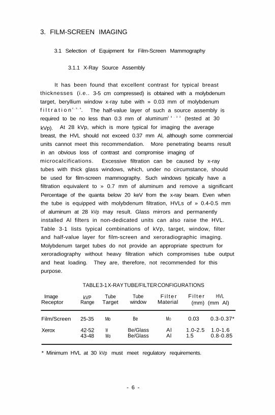
Table 3-1 lists typical combinations of kVp, target, window, filter
and half-value layer for film-screen and xeroradiographic imaging.
Molybdenum target tubes do not provide an appropriate spectrum for
xeroradiography without heavy filtration which compromises tube output
and heat loading. They are, therefore, not recommended for this
purpose.
TABLE 3-1 X-RAY TUBE/FILTER CONFIGURATIONS
Image kVP Tube Tube F i l t e r F i l t e r HVLReceptor Range Target window Material (mm) (mm Al)
Film/Screen 25-35 Mo Be MO 0.03 0.3-0.37*
Xerox 42-52 W Be/Glass Al 1.0-2.5 1.0-1.643-48 Mo Be/Glass Al 1.5 0.8-0.85
* Minimum HVL at 30 kVp must meet regulatory requirements.
- 6 -
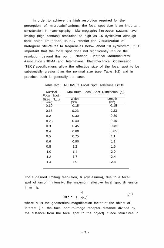
In order to achieve the high resolution required for the
perception of microcalcifications, the focal spot size is an important
consideration in mammography. Mammographic film-screen systems have
limiting (high contrast) resolution as high as 16 cycles/mm although
their noise limitations usually restrict the visualization of
biological structures 7 to frequencies below about 10 cycles/mm. It is
important that the focal spot does not significantly reduce the
resolution beyond this point. National Electrical Manufacturers
Association (NEMA)8 and International Electrotechnical Commission
( IEC)9 specifications allow the effective size of the focal spot to be
substantially greater than the nominal size (see Table 3-2) and in
practice, such is generally the case.
Table 3-2 NEHA/IEC Focal Spot Tolerance Limits
Nominal Maximum Focal Spot Dimension (feff)Focal SpotS ize ( fn o m) Width Length
(mm) (mm) (mm)0.10 0.15 0.15
0.15 0.23 0.23
0.2 0.30 0.30
0.25 0.40 0.40
0.3 0.45 0.45
0.4 0.60 0.85
0.5 0.75 1.1
0.6 0.90 1.3
0.8 1.2 1.6
1.0 1.4 2.0
1.2 1.7 2.4
1.4 1.9 2.8
For a desired limiting resolution, R (cycles/mm), due to a focal
spot of uniform intensity, the maximum effective focal spot dimension
in mm is:
( 1 )
where M is the geometrical magnification factor of the object of
interest [i.e. the focal spot-to-image receptor distance divided by
the distance from the focal spot to the object]. Since structures in
- 7 -
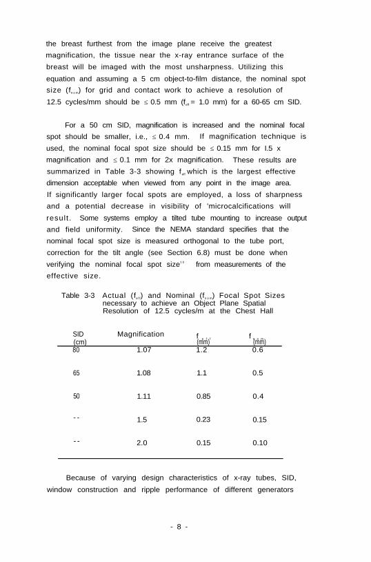
the breast furthest from the image plane receive the greatest
magnification, the tissue near the x-ray entrance surface of the
breast will be imaged with the most unsharpness. Utilizing this
equation and assuming a 5 cm object-to-film distance, the nominal spot
size (fn o m) for grid and contact work to achieve a resolution of
12.5 cycles/mm should be ≤ 0.5 mm (feff = 1.0 mm) for a 60-65 cm SID.
For a 50 cm SID, magnification is increased and the nominal focal
spot should be smaller, i.e., ≤ 0.4 mm. If magnification technique is
used, the nominal focal spot size should be ≤ 0.15 mm for I.5 x
magnification and ≤ 0.1 mm for 2x magnification. These results are
summarized in Table 3-3 showing f eff which is the largest effective
dimension acceptable when viewed from any point in the image area.
If significantly larger focal spots are employed, a loss of sharpness
and a potential decrease in visibility of 'microcalcifications will
result . Some systems employ a tilted tube mounting to increase output
and field uniformity. Since the NEMA standard specifies that the
nominal focal spot size is measured orthogonal to the tube port,
correction for the tilt angle (see Section 6.8) must be done when
verifying the nominal focal spot size1 0 from measurements of the
effective size.
Table 3-3
SID(cm)80
Actual (fe f f) and Nominal (fn o m) Focal Spot Sizesnecessary to achieve an Object Plane SpatialResolution of 12.5 cycles/m at the Chest Hall
Magnification
1.07
f e f f f n o m(mm) (mm)1.2 0.6
65 1.08 1.1 0.5
50 1.11 0.85 0.4
- - 1.5 0.23 0.15
- - 2.0 0.15 0.10
Because of varying design characteristics of x-ray tubes, SID,
window construction and ripple performance of different generators
- 8 -

(discussed later), specification of tube current can be misleading in
predicting x-ray output. Measured output exposure rate data are much
more useful. To ensure acceptable exposure times in film-screen
mammography for the range of breast thicknesses, the exposure rate
available at the entrance surface to the breast for
non-magnification work should be at least 500 mR/s at 28 kVp.
Significantly lower x-ray output results in longer exposure times and
occasional problems with patient motion and reciprocity law failure of
the film. An x-ray unit providing 500 mR/s should be capable of
sustaining its maximum current for approximately three seconds.
Table 3-4 Source Assembly Specifications(Film-screen mammography)
Target Molybdenum
Window Beryllium
Added Filtration 0.03 - 0.06 mm of Molybdenum
Half-Value Layer 0.30 - 0.37 mm of Al at 28 kVp
(with compression plate)
Focal Spot Size (nominal) ≤ 0.5 mm contact or grid at
65 cm SID
≤ 0.4 mm contact or grid at
50 cm SID
≤ 0.15 mm for 1.5x magnification
≤ 0.1 mm for 2.0x magnification
Tube Current (for 22-35 kVp range)
Large Focal Spot ≥ 100 mA for 3 s (or 500 mR/s at
breast entrance)
0.1 mm Small Focal Spot ≥ 20 mA for 6 s
0.15 mm Small Focal Spot ≥ 30 mA for 3 s
- 9 -
The x-ray tube current achievable on the small (i.e., 0.1-0.2 mm)
focal spot should be as high as possible. Currently some
manufacturers have been able to produce tubes that achieve 25 mA on a
0.1 mm focal spot and 50 mA on a 0.2 mm focal spot. Desirable source
assembly specifications are summarized in Table 3-4.
3.1.2 X-Ray Generator
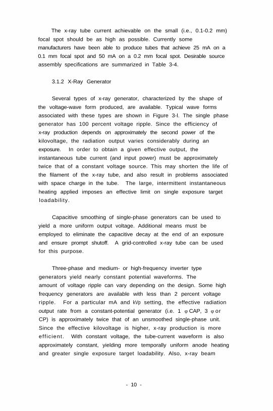
Several types of x-ray generator, characterized by the shape of
the voltage-wave form produced, are available. Typical wave forms
associated with these types are shown in Figure 3-l. The single phase
generator has 100 percent voltage ripple. Since the efficiency of
x-ray production depends on approximately the second power of the
kilovoltage, the radiation output varies considerably during an
exposure. In order to obtain a given effective output, the
instantaneous tube current (and input power) must be approximately
twice that of a constant voltage source. This may shorten the life of
the filament of the x-ray tube, and also result in problems associated
with space charge in the tube. The large, intermittent instantaneous
heating applied imposes an effective limit on single exposure target
loadabil ity.
Capacitive smoothing of single-phase generators can be used to
yield a more uniform output voltage. Additional means must be
employed to eliminate the capacitive decay at the end of an exposure
and ensure prompt shutoff. A grid-controlled x-ray tube can be used
for this purpose.
Three-phase and medium- or high-frequency inverter type
generators yield nearly constant potential waveforms. The
amount of voltage ripple can vary depending on the design. Some high
frequency generators are available with less than 2 percent voltage
ripple. For a particular mA and kVp setting, the effective radiation
output rate from a constant-potential generator (i.e. 1 φ CAP, 3 φ or
CP) is approximately twice that of an unsmoothed single-phase unit.
Since the effective kilovoltage is higher, x-ray production is more
eff ic ient. With constant voltage, the tube-current waveform is also
approximately constant, yielding more temporally uniform anode heating
and greater single exposure target loadability. Also, x-ray beam
- 10 -
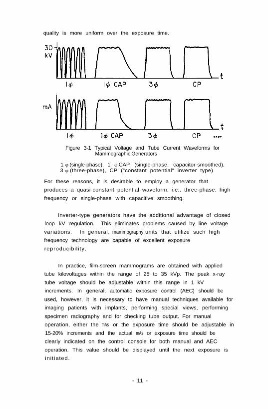
quality is more uniform over the exposure time.
Figure 3-1 Typical Voltage and Tube Current Waveforms forMammographic Generators
1 φ (single-phase), 1 φ CAP (single-phase, capacitor-smoothed),3 φ (three-phase), CP ("constant potential" inverter type)
For these reasons, it is desirable to employ a generator that
produces a quasi-constant potential waveform, i.e., three-phase, high
frequency or single-phase with capacitive smoothing.
Inverter-type generators have the additional advantage of closed
loop kV regulation. This eliminates problems caused by line voltage
variations. In general, mammography units that utilize such high
frequency technology are capable of excellent exposure
reproducibi l i ty.
In practice, film-screen mammograms are obtained with applied
tube kilovoltages within the range of 25 to 35 kVp. The peak x-ray
tube voltage should be adjustable within this range in 1 kV
increments. In general, automatic exposure control (AEC) should be
used, however, it is necessary to have manual techniques available for
imaging patients with implants, performing special views, performing
specimen radiography and for checking tube output. For manual
operation, either the mAs or the exposure time should be adjustable in
15-20% increments and the actual mAs or exposure time should be
clearly indicated on the control console for both manual and AEC
operation. This value should be displayed until the next exposure is
init iated.
- 11 -
The x-ray generator power requirements for film-screen
mammography are modest, typically less than 10 kW. The power that can
be used is usually limited by the loadability of the x-ray tube focal
spot. One other consideration is the type of power switching
employed. Most systems use solid-state switching but some
manufacturers still use mechanical contacting which provides poorer
precision of exposure control.
It is important that the generator is either designed to correct
automatically for variations in line voltage or else provide visual
indication of line voltage changes and a manual adjustment that allows
adequate correction.
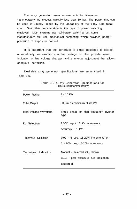
Desirable x-ray generator specifications are summarized in
Table 3-5.
Table 3-5 X-Ray Generator Specifications forFilm-Screen Mammography
Power Rating 3 - 10 kW
Tube Output 500 mR/s minimum at 28 kVp
High Voltage Waveform Three phase or high frequency invertertype
kV Selection 25-35 kVp in 1 kV increments
Accuracy ± 1 kVp
Time/mAs Selection 0.02 - 6 sec, 15-20% increments or
2 - 600 mAs, 15-20% increments
Technique Indication Manual - selected mAs shown
AEC - post exposure mAs indication
essential
- 12 -
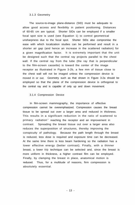
3.1.3 Geometry
The source-to-image plane-distance (SID) must be adequate to
allow good access and flexibility in patient positioning. Distances
of 60-65 cm are typical. Shorter SIDs can be employed if a smaller
focal spot size is used (see Equation 1) to control geometrical
unsharpness due to the focal spot. Shorter SIDs also compromise the
ease with which localization studies can be performed and result in a
shorter air gap (and hence an increase in the scattered radiation) for
a given magnification factor. It is extremely important that the unit
be designed such that the central ray projects parallel to the chest
wall. If the central ray from the tube (the ray that is perpendicular
to the film-screen cassette) is toward the center of the image
receptor as illustrated in Figure 3-2b, a few mm of tissue close to
the chest wall will not be imaged unless the compression device is
moved in or out. Geometry such as that shown in Figure 3-2a should be
employed so that the plane of the compression device is orthogonal to
the central ray and is capable of only up and down movement.
3.1.4 Compression Device
In film-screen mammography, the importance of effective
compression cannot be overemphasized. Compression causes the breast
tissue to be spread out over a larger area and reduced in thickness.
This results in a significant reduction in the ratio of scattered to
primary radiation1 1 reaching the receptor and an improvement in
contrast. Spreading the breast tissue out over a larger area also
reduces the superposition of structures, thereby improving the
conspicuity of pathology. Because the path length through the breast
is reduced, less dose is required and exposure time can be decreased.
At the same time there is less beam hardening so the radiation has a
lower effective energy (better contrast). Finally, with a thinner
breast, a lower kVp technique can be selected and, since the breast is
more uniform in thickness, a higher contrast film can be employed.
Finally, by clamping the breast in place, anatomical motion is
reduced. Thus, for a multitude of reasons, firm compression is
absolutely essential.
- 13 -
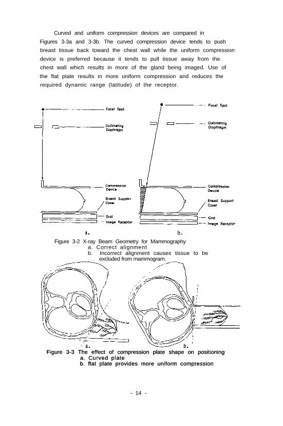
Curved and uniform compression devices are compared in
Figures 3-3a and 3-3b. The curved compression device tends to push
breast tissue back toward the chest wall while the uniform compression
device is preferred because it tends to pull tissue away from the
chest wall which results in more of the gland being imaged. Use of
the flat plate results in more uniform compression and reduces the
required dynamic range (latitude) of the receptor.
Figure 3-2 X-ray Beam Geometry for Mammographya. Correct alignmentb. Incorrect alignment causes tissue to be
excluded from mammogram.
Figure 3-3 The effect of compression plate shape on positioningFigure 3-3 The effect of compression plate shape on positioninga. Curved platea. Curved plateb. flat plate provides more uniform compressionb. flat plate provides more uniform compression
- 14 -
To minimize patient discomfort, it is desirable that compression
can be released remotely from the control console after exposure.
3.1.5 Grid
In mammography of dense or large breasts, image contrast can be
reduced markedly by scattered radiation from the breast being recorded
by the imaging system. The scatter-to-primary ratio for a breast of
average size and density can be 0.6 or greater 1 1. The use of a grid
significantly improves image contrast for large or dense breasts. To
avoid excessive increase in patient dose, the grid should have a high
transmittance of primary radiation. For this reason, carbon-fiber
covers and fiber-interspace material are often used. Because of the
low energies used in mammography it is important that the covers be of
uniform construction so that structural artifacts are not introduced.
Typically, a mammographic grid can reduce the scatter-to-primary ratio
at the image receptor by a factor of 3 or more while requiring at
least a two-fold increase in exposure if the kilovoltage is not raised
(see Section 3.2.1). It has been suggested that a grid will
significantly improve the diagnostic quality of mammograms in about
20% of cases12. Where women receive periodic mammography, previous
examinations should be used to assess the need for a grid.
Reciprocating grids may produce grid lines in cases where the
exposure only takes place over a few oscillations of the grid. I t i s
important that the grid assembly be sufficiently rigid that grid
motion is not impeded when the breast is under vigorous compression.
High strip density (approx. 80 lines/cm) aluminum interspace
grids that are very thin are also available. These are designed to be
placed in or directly above the film-screen cassette and are intended
for stationary use. In mammograms produced with stationary grids,
grid lines are evident upon close inspection and may interfere with
the perception of small, subtle microcalcifications.
High strip density aluminum interspace grids with a grid ratio of
3.5:1 have slightly greater Bucky factors than reciprocating 5:1 fiber
interspace grids of lower strip density. In addition, the aluminum
interspace grids do not provide the same degree of contrast
- 15 -
improvement. Other practical problems encountered with stationary,
high strip density grids are: 1) several grids are needed for
efficient patient throughput if they are placed in the film-screen
cassettes, 2) they can be easily damaged if they are not mechanically
secured to the front of the cassette, and 3) non-uniform grid lines
can result in local variations in image density.
In mammography, the automatic exposure-control (AEC) detector is
normally located behind the image receptor. The AEC should be capable
of maintaining optical density within ± 0.15 OD as the peak
kilovoltage is varied from 25 to 35; and as the breast thickness is
varied from 2.5 to 8 cm for each technique - nongrid, grid, and
magnification. A range of density selections should be available with
each increment increasing or decreasing the film-screen exposure by
≈ 15-20%. In addition, there should be adjustments to provide proper
compensation for different film-screen combinations. A desirable
capability, which would reduce repeats, is for the unit to select the
correct AEC mode, focal spot size and mA automatically by sensing the
presence of the Bucky assembly or the magnification platform. [Manual
override must also then be provided.]
Many of the current mammographic units operated in AEC mode have
difficulty in yielding images of constant optical density as breast
thickness and tube potential are varied. This can be due to several
effects: reciprocity law failure of the film for long exposures
through large breasts, beam hardening effects on the sensitivity of
the sensor, variation in scattered radiation, sensor offset currents,
etc.
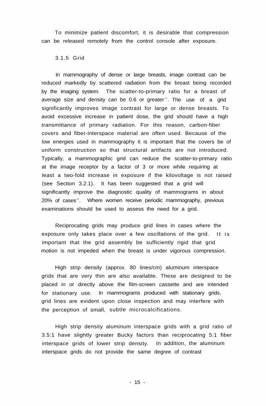
Shown in Figure 3-4 are AEC responses for four typical
mammography units15. To compensate for AEC deficiencies on existing
equipment, one can develop an AEC density setting/breast thickness/kVp
technique chart1 3. This is accomplished by first measuring the film
density versus phantom thickness (typically for PMMA* or BR12**
* poly-methyl-methacrylate, e.g., Lucite, Plexiglas, Perspex** a tissue-equivalent plastic designed to mimic the attenuation
of the breast14
- 16 -
Figure 3-4 Breast thickness tracking with typical AECdevices on commercial mammography units(from LaFrance1 5)
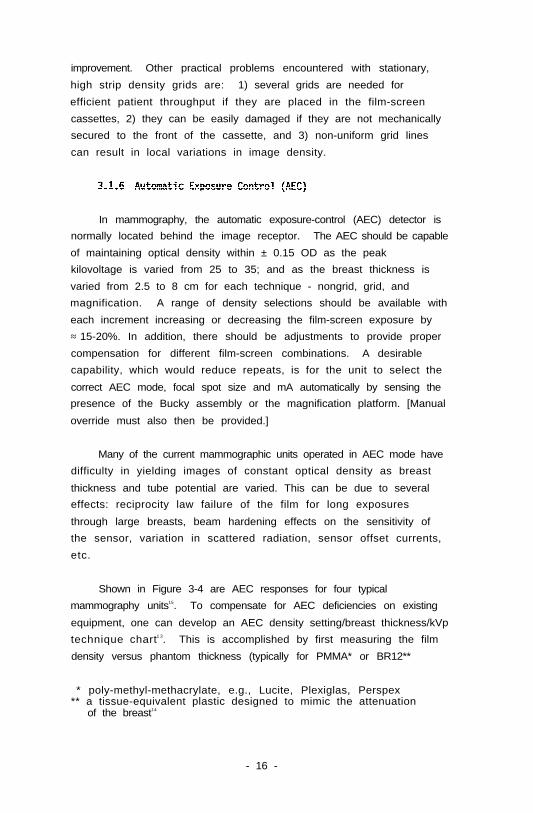
Figure 3-5 AEC thickness tracking with and withoutadditional compensating circuitry (from LaFrance15)
phantoms) for an AEC density setting of "0" and the x-ray tube voltage
of interest. For thicknesses where the density is incorrect, the +/-
AEC density setting should be adjusted to bring the film density
within the desired range and this setting recorded. An AEC technique
- 17 -
chart can thus be developed by repeating this process in a systematic
manner provided that a sufficient range of AEC density settings is
available.
Compensation circuits have been developed15 to maintain
approximately constant density over the normal range of breast
thicknesses and kilovoltage settings and for the different techniques
- nongrid, grid, and magnification. Figure 3-5 compares the density
tracking of a modern mammography unit at 28 kVp before and after the
installation of such a device. The modification makes the short AEC
exposures shorter, leaves the exposure times for average (4-5 cm
thick) breasts unchanged, and lengthens the long exposure times.
Recently some manufacturers have introduced improvements in their
AEC units intended to yield more consistent film densities across
varying kVp and breast thickness and densities. These include short
pre-exposure "test shots", multi-element sensors, and automatic
sensing of compressed breast thickness by means of an encoder on the
compression plate.
3.1.7 Choice of Film-Screen Combination
In the selection of screens, film, cassettes, film processors and
chemicals for use in mammography, it is important to consider i) film
gradient, ii) system speed, iii) film-screen blurring and iv) noise.
Once the receptor combination is selected, proper processing is
essential. Processing will be discussed in Section 3.3.
3.1.7.1 Film Gradient
Film gradient is defined as the slope of the curve of optical
density versus log(exposure). Gradient determines how changes in the
optical density (OD) in the mammogram will result from the variations
in x-ray intensity across the breast. Film gradient is affected by
1) film type, 2) processing conditions (solutions, temperature, time,
agitation, replenishment rate), 3) fog level (storage, safelight,
light leaks) and 4) the optical density of the exposed film. The
characteristic curves of six systems are shown in Figure 3-7a. The
trend is to use mammographic films with high film gradient, i.e. with
- 18 -
the maximum slope of the characteristic curve being between 2.8 and
3.5. Maximum gradient occurs at different OD for different film types
(Figure 3-7b), which may affect the optimum exposure for that film.
It is important to note that overall radiographic contrast is
influenced by both subject contrast and film gradient. Therefore, a
mammogram of acceptable contrast is best obtained by 1) use of
appropriate beam quality, 2) firm compression, 3) use of a grid when
necessary, and 4) properly processed high-contrast film.
Figure 3-7a Typical characteristic curves of combinations
(from Yaffe1 6)of screens and films available for mammography
Figure 3-7b Gradient vs. Optical Density for thecharacteristic curves in figure 3-7a.
- 19 -
Note that the characteristic curves of some mammographic films
still have a significant gradient above optical density 3.0. Useful
image contrast (e.g. near the skin line of the breast) can be obtained
if the dark parts of the image are viewed with a bright light, or
on properly masked high intensity lightboxes with low ambient room
light levels.
3.1.7.2 Film Speed
As indicated in Figure 3-7a, the speed of the image-receptor
system and, therefore, radiation dose depends on the type of
intensifying screen(s), and type of film. Both speed and gradient
depend critically on film processing (see Section 3.3).
Another factor relating to film speed is reciprocity law failure.
This phenomenon becomes important when long exposure times are
required e.g., when grids or small focal spots for conventional or
magnification techniques (low mA settings) are used. The definition
given for exposure, (E = I x T) implies that the response of the film
to radiation of a given quality will be unchanged if the product of
intensity (I) and exposure time (T) remains the same i.e., there is
reciprocity between I and T.
This relation holds well for direct x-ray exposures: however, for
exposure of film to light, it fails when long exposure times (greater
than 1 second) are used. When reciprocity law failure occurs,
additional exposure may be required to provide the proper optical
density on the mammogram. An example of technique adjustment due to
reciprocity law failure is shown in Table 3-6. A properly designed
automatic exposure control system should provide compensation for film
reciprocity failure, (however, in underpowered mammography units this
compensation may cause the unit to reach "backup time" on an
exposure). Since increased exposures due to reciprocity law failure
increase dose and also contribute to motion unsharpness, faster
film/screen/processing combinations are recommended for underpowered
units. Not all films have the same reciprocity-law failure
characteristics, so that tests on large, dense breasts (or phantoms)
should be made before a receptor combination is selected.
- 20 -
Table 3-6 Example of exposure time increaseadjustment due to the use of a gridand film reciprocity law failureeffect (from Haus1 7)
Original technique (non-grid): 1.0 seconds
Exposure time increase due to grid 200 %
Exposure increase due to film reciprocity law 15 %
failure in extending time from 1s-2s
New technique (grid) 2.3 seconds
3.1.7.3 Film-Screen Blurring
For film-screen mammography, light diffusion (spreading of the
light emitted by the screen before it reaches the film) causes
blurring. Factors influencing blurring include 1) screen phosphor
thickness, 2) screen phosphor particle size, 3) light-absorbing dyes
and pigments in the screen, and 4) film-screen contact. Film-screen
combinations for mammography have traditionally utilized a single,
high-definition screen in contact with a single emulsion film
(Figure 3-8). The single screen is used as a back screen for
Figure 3-8 One- and two-screen image receptor configurations. Thedouble-screen, double-emulsion film combination producesimages with only slightly greater blur than theone-screen, single-emulsion film combination. This is dueto the asymmetrical screen design (a significantlythinner front screen) and use of a reduced-crossover filmin the combination illustrated on the left (from Haus 1 7) .
- 21 -
mammography so that the majority of x-ray absorption takes place at as
short a distance as possible from the film emulsion. If the screen
were used as a front screen, x-ray absorption would be highest in the
plane of the screen which is furthest from the screen-emulsion contact
surface. This causes greater light spread (blur) due to a greater
diffusion distance. Factors in screen design which influence
resolution and speed are illustrated in Figure 3-9a and b.
Mammographic film-screen combinations have very high resolution
compared with combinations used for conventional radiography
(Figure 3-10). Both parallax and crossover, which limit resolution in
conventional systems, are eliminated in a single, back screen
configuration. Single emulsion films, however, have the disadvantage
that emulsion coating defects are more apparent than on those with
double emulsion.
Cassettes designed for mammography should have front panels which
provide both low x-ray absorption and intimate film-screen contact to
minimize blur. Heat-sealed vacuum bags allow a slight reduction in dose
and provide good film-screen contact.
Figure 3-9a Effect of screen thickness 3-9b Effect of dyes andon speed and resolution of reflective backingsfilm-screen systems. A on speed andfront screen is shown, but resolution inthe same effect occurs forrear screens. (see Fig. 3-11a)
- 22 -
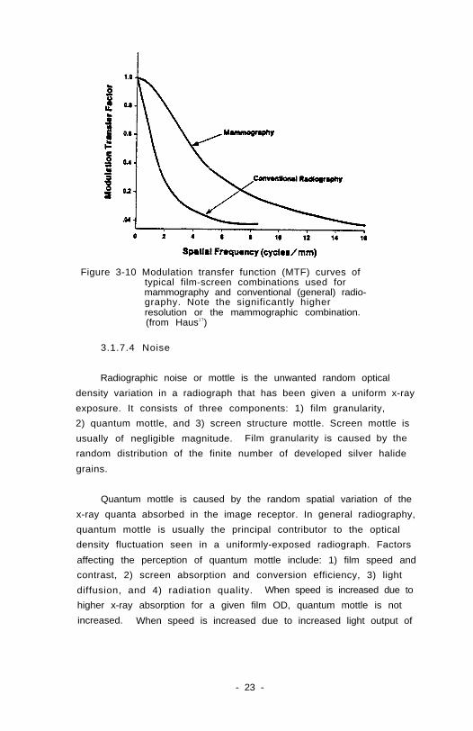
Figure 3-10 Modulation transfer function (MTF) curves oftypical film-screen combinations used formammography and conventional (general) radio-graphy. Note the significantly higherresolution or the mammographic combination.(from Haus1 7)
3.1.7.4 Noise
Radiographic noise or mottle is the unwanted random optical
density variation in a radiograph that has been given a uniform x-ray
exposure. It consists of three components: 1) film granularity,
2) quantum mottle, and 3) screen structure mottle. Screen mottle is
usually of negligible magnitude. Film granularity is caused by the
random distribution of the finite number of developed silver halide
grains.
Quantum mottle is caused by the random spatial variation of the
x-ray quanta absorbed in the image receptor. In general radiography,
quantum mottle is usually the principal contributor to the optical
density fluctuation seen in a uniformly-exposed radiograph. Factors
affecting the perception of quantum mottle include: 1) film speed and
contrast, 2) screen absorption and conversion efficiency, 3) light
diffusion, and 4) radiation quality. When speed is increased due to
higher x-ray absorption for a given film OD, quantum mottle is not
increased. When speed is increased due to increased light output of
- 23 -
the screen per absorbed x-ray or increased film speed (faster film or
increased developer temperature or time), fewer x-rays are used to
form the image and, therefore, quantum mottle is increased.
In mammography, quantum mottle may not be the limiting factor
governing noise because of the high quantum efficiency (approximately
70 percent) of the screen, low average energy of the photons and the
relatively low light emission in the screen. in many cases film
granularity is the primary noise source18 and this is always the case
at spatial frequencies higher than a few cycles per mm. This suggests
that image quality might be improved by the use of finer grained film.
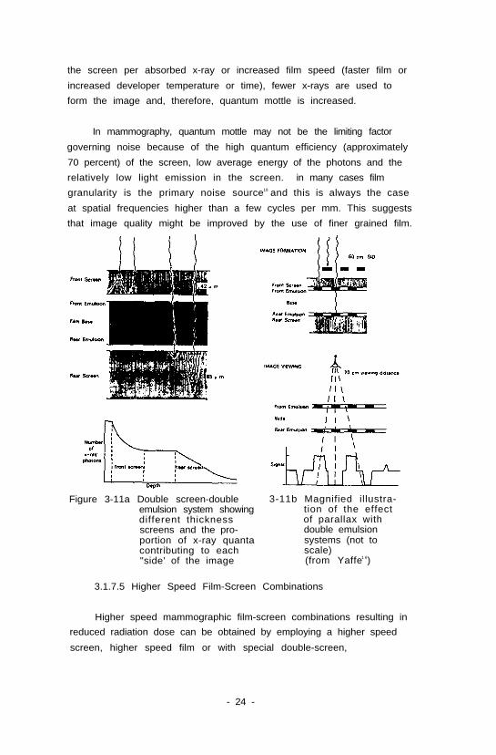
Figure 3-11a Double screen-doubleemulsion system showingdifferent thicknessscreens and the pro-portion of x-ray quantacontributing to each"side' of the image
3-11b Magnified illustra-tion of the effectof parallax withdouble emulsionsystems (not toscale)(from Yaffe1 6)
3.1.7.5 Higher Speed Film-Screen Combinations
Higher speed mammographic film-screen combinations resulting in
reduced radiation dose can be obtained by employing a higher speed
screen, higher speed film or with special double-screen,
- 24 -
double-emulsion low-crossover film systems (see Figures 3-8, 3-9,
3-11, Kimme-Smith1 9, and Oestmann2 0). Assuming all other factors are
optimized, systems are generally less sharp and present more noise
(see previous section) than images produced using a conventional
single-screen, single-emulsion combination.
In double-coated radiographic film, light photons may pass
through one emulsion layer and through the film support to be absorbed
by silver halide crystals in the other emulsion layer. The light
which passes through the film to expose the opposite emulsion is
called "crossover" or "printthrough". The resultant image blurring
has historically prevented the use of such film-screen systems for
mammography. Special anti-crossover mechanisms have been
incorporated to minimize this effect in recently-introduced products.
Viewing parallax (see Fig 3-11b) is the ultimate limit in the use of
double emulsion films, since the image Is formed with a front-to-back
divergent beam determined by the SID while the film will be viewed at
close range for examination of fine details.
In some situations, the x-ray unit may be the major cause of
image blur resulting from motion blur due to long exposure times or
geometric blur due to focal spot size and magnification. For these
situations, the higher-speed film-screen combination may produce
mammograms with less overall image blur because shorter exposure times
and/or a smaller focal spot size can be selected than possible when
employing lower-speed, higher-resolution combinations.
3.2 Technique Selection
3 . 2 . 1 kVp
X-ray tubes designed for film-screen mammography usually have a
molybdenum (Mo) target, a thin beryllium window, instead of the more
absorbing pyrex glass used on normal tubes, and a molybdenum filter of
about 0.03 mm thickness. Such tubes are operated in the 22 to 35 kVp
range* and commonly have a rotating anode in order to achieve currents
of 100-200 mA.
* The range 22-25 kVp is normally reserved for biopsy specimenradiography.
- 25 -

Some units designed for film-screen mammography may contain a
beryllium window, tungsten (W) target tube with a total filtration
equivalent to ≈ 0.5 mm aluminum (Al) or an added filtration of 0.03 mm
molybdenum (Mo).* In order to provide high quality film-screen
images, these tungsten target tubes must be operated at a voltage
setting of 3 to 5 kVp lower than those used with molybdenum target
tubes. The lower kVp requires increased exposure times and tube
loading.
The choice of kilovoltage should be based on the expected
breast characteristics of the patient and a technique chart should be
constructed for each mammography unit. If the average breast is
imaged at 25-28 kVp, an increase by 1-4 kVp flay be used for denser
breasts and a reduction by 1-3 kVp for thin or flaccid breasts. Since
"constant potential" waveforms give a higher effective energy
spectrum, a drop in peak potential by 1-2 kVp may be necessary to
obtain the same contrast as with single-phase systems or those with
significant voltage ripple. Measuring and matching HVL is the best
way to obtain equivalent contrast.
When grids are used in mammography, it is common practice to
increase the kilovoltage by 2-3 kVp in order to offset part of the
exposure increase necessitated by insertion of the grid5.
3.2.2 Exposure Time
The maximum tube current used in dedicated mammography systems
is normally limited by the instantaneous loadability of the focal spot
to 100-200 mA for the larger spot (0.3 to 0.6 mm) on rotating anode
tubes, and 15-50 mA on the smaller spot (0.1 to 0.2 mm) used for
magnification studies. Exposures should be as short as possible to
minimize unsharpness due to patient motion, and, therefore, maximum
tube current should be selected whenever possible. When imaging
large, dense breasts with the small focal spot, exposure times in
excess of 3s may be unavoidable. The combination of generator and AEC
should be capable of reliably controlling exposures as short as 30 ms.
* Note that the total filtration must be such that the minimumhalf value layer (HVL) requirement of 0.3 mm Al at 30 kVp 2 9 , 3 3 is met.
- 26 -
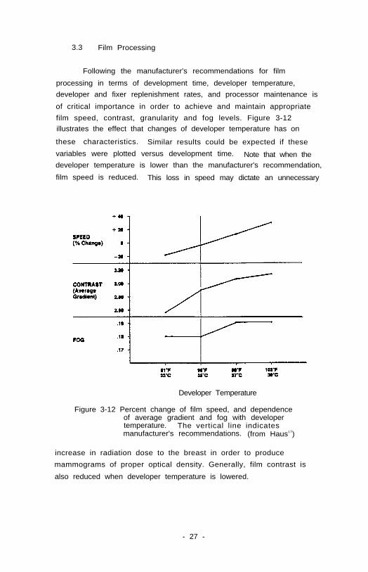
3.3 Film Processing
Following the manufacturer's recommendations for film
processing in terms of development time, developer temperature,
developer and fixer replenishment rates, and processor maintenance is
of critical importance in order to achieve and maintain appropriate
film speed, contrast, granularity and fog levels. Figure 3-12illustrates the effect that changes of developer temperature has on
these characteristics. Similar results could be expected if these
variables were plotted versus development time. Note that when thedeveloper temperature is lower than the manufacturer's recommendation,
film speed is reduced. This loss in speed may dictate an unnecessary
Developer Temperature
Figure 3-12 Percent change of film speed, and dependenceof average gradient and fog with developertemperature. The vertical line indicatesmanufacturer's recommendations. (from Haus1 7)
increase in radiation dose to the breast in order to produce
mammograms of proper optical density. Generally, film contrast is
also reduced when developer temperature is lowered.
- 27 -
3.3.1 Extended Process Cycle
As is apparent in Figure 3-12, increasing developer temperature
can achieve higher film speed and contrast. Similar results can be
achieved by increasing developer immersion times. This is commonly
referred to as "push processing" or extended process cycle (EPC) 21,22 .
EPC can be successfully used with most single emulsion coated filmswhich contain conventional 3-dimensional silver halide grains because:
1) The relatively high amount of silver halide contained in some
single emulsion film may not be fully developed in the normal process
cycle. With EPC, silver halide grains that were previously exposed
but not developed are activated, resulting in higher speed and
contrast; and 2) previously unexposed grains in proximity to exposed
silver halide grains are added to the previously developed grains.
It is also important to note that push processing does not
provide comparable film speed and film contrast increases for all film
emulsions (single or double emulsion). Tabular and mono-dispersed
grain emulsions are designed to be processed using specified chemical
solutions and are relatively insensitive to changes in development
time and/or temperature.
Increased film contrast may enhance perception of details in
the mammogram. The increased film speed will result in higher quantum
noise in the image because fewer quanta are required to obtain a given
optical density. Higher film contrast will make the noise (as well as
the signal) more visible. Film fog may increase with increased
developer temperature and/or time. Developer stability may also be
affected when developer temperatures higher than recommended are used
and, therefore, attention to quality control is especially important.
If EPC is used, the film processor should be dedicated to
processing only the mammographic film selected for that process. The
EPC can be achieved on many commercially-available film processors by
modifying the film transport mechanism and/or adjusting developer bath
temperature. It is also important that the replenishment rate be
adjusted properly for EPC if the transport speed is reduced.
- 28 -
Replenishment rate adjustment to the requirements of the
mammographic film is important for both standard and EPC because in a
general x-ray environment, processors are set up to replenish
developer and fixer chemicals at a specified volume per 14-inches
(35 cm) of double emulsion film travel at a given film throughput per
day. Replenishment rate adjustment must be performed by changing the
setting on the replenishment pumps. Each film processor (regardless
of manufacturer) must have these rates set and periodically verified
to maintain processing control.
3.3.2 Storage of Film Processing Chemicals
Chemicals may be obtained in either pre-mixed or "user-to-mix"
format. It is important, especially in the case of pre-mixed
chemicals that large reserve stocks are not kept on hand but rather
supplies are obtained on a frequent and regular basis in order to
minimize chemical deterioration associated with aging.
Chemicals should be stored in an environment consistent with
the manufacturer's specifications. Since chemical fumes can cause
deterioration of radiographic film, chemicals must be kept in a
location separate from where film reserves are stored.
Pre-mixed solutions are occasionally of variable quality and
consequently it is important that the processor be checked with a
sensitometric strip after solutions have been changed and the daily
sensitometry should be closely monitored whenever a new batch of
replenisher is introduced.
3.3.3 Preparation of Replenishment Chemical Solutions
In order to prevent chemical deterioration as a result of
oxidation, contamination or precipitation during shelf storage in
small facilities (or in satellite processors in large facilities where
there is infrequent processing due to specialized workload), only
adequate volumes of replenishment solutions to meet normal weekly
requirements should be prepared at any one time.
- 29 -
Preparation of replenisher should be done in accordance with
the manufacturer's specifications and sensitometric strips should be
closely monitored after the new batch of replenisher is introduced.
In large facilities, a regular replenishment schedule should be
established and maintained.
For dedicated processors which have a low workload (less than
30 films per day), "flood replenishment"23 may be required in order to
maintain the stability of the processing characteristics. Rather than
replenishing using a fixed volume of solution per sheet of film
processed, one provides a specific volume of solution per unit of
time. The solution used in this case is standard replenisher mixed
with starter.
3.3.4 Storage of Unprocessed X-ray Films
X-ray film must be handled and stored with great care if it is
to remain in good condition. Even under the best conditions, film
will gradually deteriorate. Generally, higher speed film has a
shorter shelf life than slower film.
When ordering film stock, intake should be adjusted to the rate
of use and only stock sufficient to meet demands without a large
reserve supply should be kept.
When new film reaches a facility, boxes should be date-stamped so
that older stocks may be identified and used first, always ensuring
that the film is used before the expiry date. Film boxes should be
stored vertically on shelves in an environment where the temperature
is preferably in the region of 10°C (50°F) and does not rise above
20°C (68°F), with relative humidity in the region of 50%. Since
dampness and high temperatures have the most damaging effects on
photographic materials, rooms with damp floors and walls or subject to
sudden temperature changes and condensation are to be avoided.
Horizontal storage may lead to emulsion "pickoff", small clear spots
on the film which may mimic microcalcifications. Film should be
stored away from any possibility of exposure by ionizing radiation,
and isolated from processing chemical fumes.
- 30 -
3.4 Viewing Conditions
The subtle contrasts which are recorded in the mammographic
image may not be perceived if the film is viewed under less than
optimum conditions. This requires that the amount of extraneous light
reaching the eye be minimized. The viewing room should be dimly lit
or illuminated only by light passing through the film. Viewboxes that
are not being used should be turned off and wherever possible,
portions of the viewbox that are not covered by the mammogram should
be masked. It is desirable that the film on the outside of the image
of the breast be exposed to x-rays so that this part of the film is
blackened and intense transmitted light does not dazzle the eye.
Since radiation falling outside the breast will primarily be absorbed
by the mammographic screen which is of high atomic number, the amount
of extra scattered radiation to the breast or to the main image will
be minimal.
A variable-intensity "bright light" operated by a foot control
should be available for scrutinizing regions of the image that are of
high optical density, for example, the skin line and nipple. To make
use of the maximum dynamic range of the film, exposures should be such
that the area immediately outside the skin line approaches the
saturation optical density of the film.
A high quality magnifying lens is necessary for investigation
of fine detail, especially microcalcifications. A variety of
specialized masking and viewing aids for mammography are commercially
available, including a hood which both eliminates extraneous light and
magnifies the image.
3.5 Quality Control
A structured quality control program must be employed to
monitor the performance of mammography equipment and to provide a
record in case of machine failure. The procedures must be performed
regularly and require careful, consistent record keeping and regular
comparison with baseline measurements obtained during acceptance
testing. When problems are noted, appropriate remedial action must be
taken with subsequent testing to verify correction of the problem.
- 31 -
In this section the elements of a quality control program are
listed. Detailed methods for carrying out these tests are given in
Section 6.
3.5.1 Processing: Sensitometric strips should be run at the
same time every operational day to monitor speed, gradient and
base-plus-fog. Films should be analyzed on a densitometer and results
recorded daily. Processor chemicals should be changed and the
processor thoroughly cleaned at the manufacturer's recommended
intervals. Sensitometric strips should then be run and
uniformly exposed films should be processed to detect roller wear.
3.5.2 Film Density: Uniformity and consistency of image
density and the actual working OD should be checked and recorded
weekly by imaging a uniform 4.2 cm PMMA phantom. This exposure should
be made for the techniques commonly employed with the equipment -
non grid, grid and magnification, using AEC or manual technique,
whichever is used for patients. If the density changes by more than
0.15 OD from the established working density, the reason for the
change should be determined and appropriate corrective action taken.
The uniform phantom image should also be checked for processing and
other artifacts.
3.5.3 Image Contrast: Measurements of the differences in OD,
either behind two selected steps of a thin aluminum step wedge or
behind a thin PMMA disc on top of the uniform phantom and a point in
the center of the phantom should be performed and recorded weekly.
This test can demonstrate changes in filtration, kVp, film emulsion
and processor characteristics. While image contrast measurements help
monitor overall changes in mammographic performance, they do not
diagnose specific problems as do some of the other quality control
procedures. A large change or long term drift in values of either
density or contrast indicates that more specific tests of individual
parameters affecting contrast - film processing, film gradient, x-ray
tube kilovoltage (and waveform) and beam quality - should be carried
out to localize the actual problem.
- 32 -
3.5.4 Entrance Skin Exposure (ESE) (free in air): The ESE
associated with imaging a standard phantom should be measured at six
month intervals for the techniques commonly used - non grid, grid and
magnification. The ESE can be calculated from tube output
measurements (Section 3.5.5), if the mAs used to obtain an image is
known. Methods are described in Sections 6.4 and 6.5.
Mean glandular dose can be estimated from ESE and HVL for
specified tissue compositions using Table 5-1 or References 24, 25.
Note that exposure measurements without backscatter are required in
order to use the tables in Section 5 for the calculation of dose.
If the ESE (and associated glandular dose) change markedly in a
six month interval (i.e., >20%), the reason for the change should be
determined and appropriate corrective action taken.
To check exposure consistency, an ionization chamber can be
placed on a standard test object (approximately 4.2 cm of PMMA or
tissue-equivalent epoxy) and an exposure made under the appropriate
manual or AEC conditions and standard kVp.
3.5.5 Radiation Output: The mR/mAs for a standard kVp and
distance should be measured (Section 6.4) and recorded at six month
intervals. The mR/mAs measurement associated with the ESE
determination is satisfactory for this purpose. Radiation output is a
useful overall test of generator and tube performance and may allow
prediction of impending tube failure.
3.5.6 Focal spot failure, particularly for microfocal spots,
can be diagnosed with magnification images of high-contrast star
patterns, or using a pinhole camera (Section 6.8). There is no
recommended frequency, however a baseline star-pattern film should be
taken on acceptance testing, and saved for comparison if there is a
problem suspected with the focal spot size. Anode wobble or loss of
bias may cause increased focal spot size.
3.5.7 Half value layer: Measurements should be done every six
months in order to detect variations in beam quality due to changes in
ki lovoltage or f i l trat ion.
- 33 -
3.5.8 Screens: Uniform phantom images will enable detection of
dirty or damaged screens, The frequency of screen cleaning is
determined by usage and environment, but should be carried out at
least weekly and each screen should be checked monthly by radiography
of a uniform phantom. Visual inspection should also be carried out,
using a strong light source, rather than standard darkroom
illumination. An ultraviolet lamp provides an excellent way to find
areas of damage, as well as embedded dirt. Scratches caused by
fingernails and rings as well as creases in the screen can provide
undesirable artifacts. Good contact between screens and film can be
tested by imaging a flat copper screen of 30-40 mesh semi-annually.
Dust artifacts are more easily discernable with single emulsion
single-screen systems. Clinical images should be reviewed on a
routine basis by the technologists and radiologists to identify
art i facts.
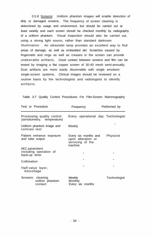
Table 3-7 Quality Control Procedures For Film-Screen Mammography
Test or Procedure Frequency Performed by
Processing quality control(sensitometry, temperature)
Every operational day Technologist
Uniform phantom image andcontrast test
Patient entrance exposureand tube output
Weekly "
Every six months and Physicistupon alteration orservicing of themachine
AEC parametersincluding operation ofback-up timer
Collimation
Half-value layer,kilovoltage
" "
" "
" "
Screens: cleaning Meeklyunifom phantom Monthlycontact Every six months
Technologist
- 34 -
4. XERORADIOGRAPHY
4.1 Selection of Equipment for Xeromammography
4.1.1 X-Ray Source Assembly
In xeromammography, x-ray tube voltages in the 42-52 kVp range
are routinely employed. Total (inherent plus added) equivalent
filtration should be 2.0-2.7 mm Al at 50 kVp for tungsten tubes and
1.6 mm Al for molybdenum tubes resulting in typical HVL's of 1.4-1.6
mm Al for W and 0.8-0.85 mm Al for MO targets. Beams with HVLs
significantly greater than 1.5 mm Al result in noticeable loss of edge
contrast of microcalcifications with only modest reduction in mean
glandular breast dose. Likewise, HVL's close to the regulatory
minimum l imit2 9 , 3 3(i.e., 0.5 mm of Al for 49 kVp) result in only
modest improvement in image quality at the expense of increased dose.
In this range of beam quality, there is no advantage to employing a
molybdenum x-ray tube target as almost all the Mo characteristic
x-rays will be absorbed by the filter. Tungsten gives rise to 75%
more bremsstrahlung x-ray production, can withstand higher heat
loading and is preferred, although MO tubes can produce equivalent
quality images at only slightly elevated doses if filtration and kVp
are carefully adjusted.
To ensure that focal spot unsharpness does not unduly degrade
xeroradiographic image quality, nominal focal spot size should be
sufficiently small for the SID and degree of geometric magnification
employed (see Tables 3-1, 3-2, 3-3 and 4-1). In order to produce
images with exposure times on the order of one second or shorter for
typical breast thicknesses, the tube current for the large focal spot
should be ≥ 200 mA. Likewise, the mA for the small focal spot should
be as high as possible. With current state-of-the-art x-ray tube
technology, this would be on the order of 50-75 mA for a 0.2 mm focal
spot (and 50 mA for a 0.15 mm focal spot). Desirable xeromammography
source assembly specifications are summarized in Table 4-l.
- 35 -
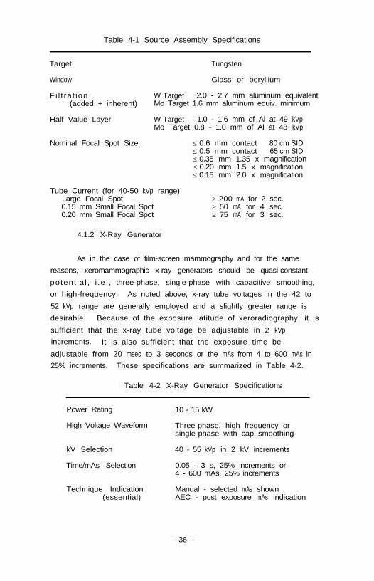
Table 4-1 Source Assembly Specifications
Target Tungsten
Window Glass or beryllium
Fi l t ra t ion W Target 2.0 - 2.7 mm aluminum equivalent(added + inherent) Mo Target 1.6 mm aluminum equiv. minimum
Half Value Layer W Target 1.0 - 1.6 mm of Al at 49 kVpMo Target 0.8 - 1.0 mm of Al at 48 kVp
Nominal Focal Spot Size ≤ 0.6 mm contact 80 cm SID≤ 0.5 mm contact 65 cm SID≤ 0.35 mm 1.35 x magnification≤ 0.20 mm 1.5 x magnification≤ 0.15 mm 2.0 x magnification
Tube Current (for 40-50 kVp range)Large Focal Spot0.15 mm Small Focal Spot0.20 mm Small Focal Spot
≥ 200 mA for 2 sec.≥ 50 mA for 4 sec.≥ 75 mA for 3 sec.
4.1.2 X-Ray Generator
As in the case of film-screen mammography and for the same
reasons, xeromammographic x-ray generators should be quasi-constant
potent ia l , i .e . , three-phase, single-phase with capacitive smoothing,
or high-frequency. As noted above, x-ray tube voltages in the 42 to
52 kVp range are generally employed and a slightly greater range is
desirable. Because of the exposure latitude of xeroradiography, it is
sufficient that the x-ray tube voltage be adjustable in 2 kVp
increments. It is also sufficient that the exposure time be
adjustable from 20 msec to 3 seconds or the mAs from 4 to 600 mAs in
25% increments. These specifications are summarized in Table 4-2.
Table 4-2 X-Ray Generator Specifications
Power Rating
High Voltage Waveform
10 - 15 kW
Three-phase, high frequency orsingle-phase with cap smoothing
kV Selection
Time/mAs Selection
40 - 55 kVp in 2 kV increments
0.05 - 3 s, 25% increments or4 - 600 mAs, 25% increments
Technique Indication Manual - selected mAs shown(essential) AEC - post exposure mAs indication
- 36 -
4.1.3 Geometry
The geometry requirements of xeromammography are similar to
film-screen units and a large (65-80 cm) SID is desirable. The
central ray should project along the chest wall to the edge of the
image receptor as illustrated in Figure 3-2a.
4.1.4 Compression Device
Some facilities employ a curved compression device for (see
Figure 3-3) for xeroradiography in order to image the ribs in the
lateral or medial-lateral views. This allows greater coverage than
with a uniform compression device, however, it may result in breast
tissue being obscured by the ribs due to improper patient positioning.
Wedge-shaped sponges are often used to facilitate positioning the
lateral view for xeroradiography.
4.1.5 Grid
Although moving grids can improve image quality in
xeromammography, the improvement isn't as marked as in film-screen
mammography. Stationary grids are not appropriate for
xeromammography, since the edge enhancement effect could cause grid
lines to be disturbing to the viewer. Because of the large dose
penalty and the small benefit, anti-scatter grids are seldom used for
xeromammography.
4.1.6 Automatic Exposure Control
Because of the exposure latitude of xeroradiography, automatic
exposure control is used less often and its requirements are less
demanding than with film-screen systems. Because of this latitude,
however, it is easy to utilize more radiation than is necessary for
xeroradiography without the obvious indications of overexposure
provided in film imaging. Care must be taken, therefore, in setting
the operating point of the AEC. As in the case of film-screen
mammography, the AEC detector is located behind the cassette and
should have a sensitive area of 10-20 cm2. Cassettes must be designed
for AEC operation. The device should be capable of holding the
- 37 -
exposure to the xeroradiographic cassette to within ± 15% as the kVp
is varied from 40 to 55 and breast thickness is varied from 2.5 to
8 cm. It is sufficient to have seven AEC density selections with each
increment increasing or decreasing the exposure to the xerographic
cassette by approximately 25%. In addition, there should be
selections for the different techniques - contact and magnification.
A post-exposure display of the exposure time or mAs used is essential
to allow the operator to monitor machine function.
4.2 Technique Selection
4 . 2 . 1 kVp
Xeroradiography is performed at potential differences of 42 to
52 kVp. Tungsten targets are preferred because doses are lower and
exposures are shorter, providing less motion blurring, although
molybdenum target tubes can be used if appropriate filtration is used.
Because the beam quality used for xeroradiography is greater than that
used for film-screen imaging, tubes with either glass or beryllium
windows are acceptable. Table 4-1 lists appropriate filtration
ranges. Positive mode xeromammography is generally performed with 2.2
mm Al total filtration at 48 kVp. Acceptable images can be produced
in the negative mode with 2.7 mm Al total filtration at 50 kVp with
approximately 30% lower ESE. If a molybdenum target tube is used* it
should have no less than 1.6 mm total Al filtration with 43 - 48 kvp
being used for either positive or negative mode.
4 . 2 . 2 F i l t e r
When a mammography unit with a molybdenum target tube is used
for both film-screen and xeroradiography* examinations, a set of two
filters is provided for the beryllium window tube and interlocked so
that the 0.03 mm Mo filter is in place for settings below 40 kVp for
film-screen imaging and the 1.0-1.5 mm Al filter is in place for
settings above 40 kVp for xeroradiography.
*Use of a molybdenum target for xeroradiography is not recommended.
- 38 -
4.2.3 Beam Quality
A wide range in the half-value layer (HVL) of the x-ray beam is
reported in the literature because total filtration varies so widely.
For most mammographic applications, the HVL, filtration, and kVp will
depend on the target material and xeroradiographic processor selected.
Table 4.1 can be used to select the correct combination of kVp and
f i l t r a t i o n .
4.2.4 Exposure Time
The duration of the exposure is expected to be in the range of
0.5 - 1.0 s, depending on the equipment. Exposure times longer than
1.0 s increase the likelihood of motion unsharpness. Very short
exposure times using high tube currents may result in focal spot
blooming. Thus, it is advisable to use an exposure time as short as
the x-ray tube and generator will allow without sacrificing spatial
resolution.
4.3 Processing
Xeromammography involves three distinct steps: a) charging the
selenium plate, b) formation of a latent image by x-ray exposure, and
c) processing to produce a final image.
Because the selenium layer is a photosensitive surface, the
plate must be charged, exposed, and developed in the dark. A
light-tight cassette is used for the x-ray exposure and the plates are
automatically loaded by the conditioner and unloaded by the processor
without the need of a darkroom.
In the first step, the selenium plate is charged uniformly by
an ion-generating device.
During the exposure, x-rays absorbed by the selenium layer
discharge the plate to a degree which is proportional to the absorbed
energy. This process leaves a residual charge distribution (latent
image) on the selenium plate.
- 39 -
In the development process, a bias potential is applied between
the plate and the development chamber. The polarity of the electric
field is selectable. In positive mode development, the toner is
attracted to the charged areas of the plate (i.e. unexposed regions);
in the negative mode, the toner is attracted to the discharged areas.
The electrostatic fringe fields near the surface of the plate control
the deposition of the toner, resulting in an image with enhanced edges
and with very wide latitude. The toner is then transferred to an
opaque paper substrate which is used to view the xeromammogram.
Negative mode xeromammograms require about two-thirds of the radiation
exposure required by positive mode. Tests at Xerox Medical Systems on
optimally adjusted processors indicate the following suggested
voltages:
negative mode: back bias = 3500V, plate charge = 1600V
positive mode, back bias = 1450V, plate charge = 1600V
4.4 Viewing Conditions
Xeromammograms are viewed using reflected light whereas x-ray
films require transillumination. Back illumination should be
minimized when viewing xeromammograms, since it will reduce
perceptibi l i ty of contrast. A magnifying lens is recommended for
questionable areas, especially for confirming or ruling out the
presence of very small features, such as microcalcifications.
4.5 Quality Control for Xeroradiography
In order to ensure that xeroradiographic images are produced at
the minimum dose compatible with high diagnostic quality, it is
necessary to monitor performance of all aspects of the imaging system
at regular intervals. This is especially true in xeroradiography
because of the wide exposure latitude which can allow problems to go
unnoticed even though radiation doses may have increased
signif icantly. In positive mode, a 1 mm halo around the skin is
indicative of a proper exposure, while in negative mode no simple rule
of thumb is available. In this section Table 4-3 outlines essential
elements of a quality control program. Methods for carrying out the
requisite tests are included in Section 6.
- 40 -
4.5.1 Exposure
For a well-filtered beam from a tungsten target (HVL around 1.5
mm Al), the optimal exposure at the receptor for selenium of thickness
of 140 µm, is 2.5 x 10- 5 C/kg (100 mR) for positive mode.
Table 4-3 Quality Control Procedures For Xeroradiography
Test or Procedure Frequency Performed by
Processing quality control Every operational day Technologist
Uniform phantom image " " " "
Dark dust all plates Weekly "
Clean all cassettes " "
Inspect and clean Every month "positioning sponges
Patient entrance exposureand tube output
Every six months andupon alteration orservicing of themachine
Physicist
Collimation " "
Half-value layer
- 41 -
"
5. DOSIMETRY
5.1 Estimation of Dose
Several major variables affect the dose to the breast in a
mammographic examination including: the choice of imaging system, film
processing, beam quality (HVL), breast compression, breast
composition, use of a grid, and working optical density. These
factors are discussed in NCRP 852. The mean glandular dose is the
preferred measure of the potential risk from mammography and can be
estimated with reasonable accuracy. Mean glandular dose can be
estimated using data from Table 5-l for a given target material when
the breast thickness, HVL, and entrance exposure (free-in-air) are
known. For women 40 years and older, the average breast composition
can be reasonably represented by a composition of 50% adipose and 50%
glandular tissue (50/50). For other compositions see the Handbook of
Glandular Tissue Doses in Mammography24.
It should be noted that the values in these tables have been
calculated for "mathematical phantoms" and will not strictly reflect
actual tissue distributions. For this reason, increased precision in
determination of HVL, breast composition and compression thickness
will not necessarily increase the accuracy of dose estimations.
T a b l e 5 - 12 4 , 2 5
Firm Compression - Uniform Breast ThicknessCraniocaudal View
50 percent (by weight) Fibroglandular Tissue Content
Mean Glandular Tissue Dose Dgn in mGy for 1 REntrance Exposure (free-in-air)
- 42 -
The procedure for determining the mean glandular dose (Dg) to
either a breast of known composition or to a dosimetry phantom is
as follows:
a. Note the target material of the x-ray tube andthe compressed breast thickness
b. Measure the HVL at the kVp of interest with thecompression plate in the beam (see Section 6.3.2).
c. Determine the entrance skin exposure, ESE,(free-in-air) in R, using methods described inSections 6.4 and 6.5.1.
d. Determine the mean glandular dose (mGy) for 1 Rentrance exposure (free-in-air) DgN f romTable 5-l or see Reference 24.
e. Dg = DgN x ESE
Table 5-2 gives data on ESE and mean glandular doses obtained
by the Nationwide Evaluation of X-ray Trends (NEXT)26 survey conducted
in 1985 by the Conference of Radiation Control Program Directors and
the Center for Devices and Radiological Health. Note that the values
are for a phantom composed of PMMA and wax to yield an equivalent
thickness of 4.3 cm PMMA which approximates a 4.7 cm thick compressed
breast of 50/50 composition. This is considered to be representative
of a breast of average attenuation. This information was collected
before the introduction of a generation of more sensitive film-screen
systems (ca. 1986).
Table 5-3 gives more recent unpublished NEXT 27 data from
surveys in 1988 where a phantom composed of PMMA and wax to yield an
equivalent thickness of 3.84 cm PMMA was used. Since the ACR (see
Section 6.10.2) accreditation phantom has approximately this
equivalent thickness, these data can be compared to measurements made
with the ACR phantom. The 3.84 cm phantom is typical of a 4.2 cm
thick compressed 50/50 breast, which is thinner than the average
breast. The ACR phantom may be useful for intercomparison purposes,
however, more realistic determination of average exposure and
glandular dose can be obtained by use of a 4.2 cm PMMA-equivalent
phantom. For users of the ACR phantom, this can be easily achieved by
adding a slab of PMMA 0.36 cm (5/32") thick under the phantom for
- 43 -
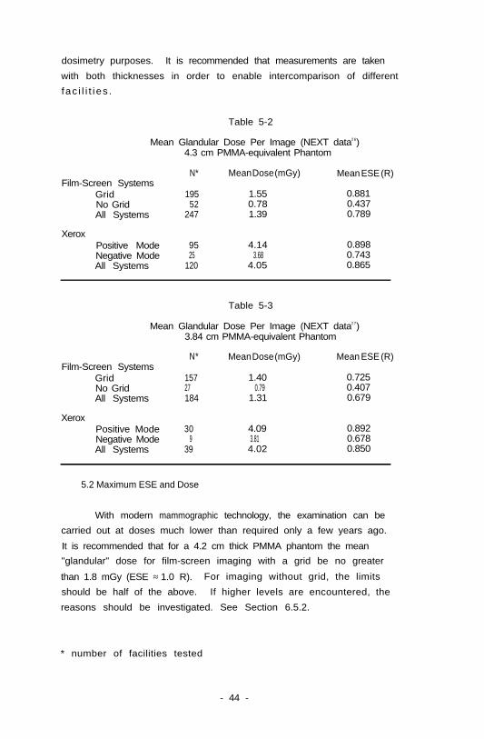
dosimetry purposes. It is recommended that measurements are taken
with both thicknesses in order to enable intercomparison of different
fac i l i t i es .
Table 5-2
Mean Glandular Dose Per Image (NEXT data26)4.3 cm PMMA-equivalent Phantom
Film-Screen SystemsGridNo GridAll Systems
N*
19552
247
Mean Dose (mGy) Mean ESE (R)
1.55 0.8810.78 0.4371.39 0.789
XeroxPositive Mode 95 4.14 0.898Negative ModeAll Systems 120
25 3.68 0.7434.05 0.865
Table 5-3
Mean Glandular Dose Per Image (NEXT data27)3.84 cm PMMA-equivalent Phantom
Film-Screen SystemsGridNo GridAll Systems
XeroxPositive ModeNegative ModeAll Systems
N*
157
184
30
39
Mean Dose (mGy) Mean ESE (R)
1.40 0.72527 0.79 0.407
1.31 0.679
4.09 0.892 9 3.81 0.678
4.02 0.850
5.2 Maximum ESE and Dose
With modern mammographic technology, the examination can be
carried out at doses much lower than required only a few years ago.
It is recommended that for a 4.2 cm thick PMMA phantom the mean
"glandular" dose for film-screen imaging with a grid be no greater
than 1.8 mGy (ESE ≈ 1.0 R). For imaging without grid, the limits
should be half of the above. If higher levels are encountered, the
reasons should be investigated. See Section 6.5.2.
* number of facilities tested
- 44 -
6. TESTING OF MAMMOGRAPHY UNITS FOR ACCEPTANCEAND QUALITY CONTROL
In this chapter, methods for evaluating performance of
mammographic systems are described. These tests should form the basis
of an acceptance testing protocol for newly-installed equipment.
Acceptance testing is necessary to verify that the equipment not only
meets legal requirements, but also performs according to the
specifications agreed upon by the purchaser and the supplier. It
should be done before the equipment is used on patients and before
final payment is authorized.
During acceptance testing, baseline measurements are obtained
for use in the regular quality-control programs. Quality control (QC)
testing should provide a practical method for monitoring changes in
equipment performance. Since QC tests must be done on a routine
basis, they should be straightforward to perform and not require
difficult-to-obtain test equipment. Once a problem has been
identified by the QC tests, it may be necessary to isolate its cause
using more sophisticated tests and equipment. Where acceptance tests
differ from quality control methods, this is indicated in the text.
The standards of construction and performance of mammography
equipment discussed in this chapter may be useful in developing a
specification document for the purchase of mammographic systems.
6.1 Mechanical System
Dedicated mammographic x-ray systems normally employ a "C-arm"
geometry and must always incorporate a compression mechanism for
patient positioning. Smooth operation of all moving parts and
assemblies must be verified and electro-mechanical locks, interlocks,
and other safety functions must be tested thoroughly.
6.1.1 General Installation
As dedicated mammography systems are often of free-standing
design, one should verify that the entire system is installed properly
- 45 -
in the examination room and is stable. The control unit should be
level and there should be convenient access for service and
maintenance. There should be no obstruction which hinders the range
of mechanical motions provided by the system.
It should be ensured that the mechanical stops and magnetic
locks are properly set and adjusted to prevent accidental motion or
collision against other mechanical parts or the patient. All
mechanical motions provided with the system must be installed with
proper cushions or bumpers at the extreme limits of the available
motion ranges.
The up-and-down translation motion and the rotation of the
C-arm must be smooth and easily locked (electromagnetically or
mechanically) in the desired position. The image receptor compartment
must secure the image receptor in its proper position, yet allow the
radiographer to insert and withdraw it with ease. All surfaces in
contact with the patient during positioning and exposure must be free
of sharp edges and rough surfaces, and also be electrically safe.
6.1.2 Compression Device
The compression plate should be parallel to the image receptor
support and aligned as in Figure 3-2a. The plate should be located
such that a line projected from the focal spot, orthogonal to the
image receptor, intersects both the bend in the compression plate and
the edge of the receptor proximal to the chest wall of the patient.
Alignment of the compression plate can be tested by adjusting
the compression plate to its normal position ( ≈ 5 cm above the
breast support), placing a high contrast linear object (e.g. a paper
clip or wire) on the plate against the bend and producing a
radiograph.
If possible, the image receptor should be placed on the table in
such a way that it extends over the edge (toward the patient) by a few
centimeters. The normal position of the edge of the receptor and the
edge of the light localizer field can be identified by placing other
objects on the receptor. To avoid overexposure of the film during the
- 46 -
test , it may be necessary to place an attenuating phantom in the
beam (conveniently taped over the tube port after the localizer
position has been marked).
The processed image will then identify the projection of the
bend in the compressor with respect to the normal position of the edge
of the image receptor. It will also demonstrate whether the radiationbeam is congruent with the light localizer field and allow
determination of the extent of the radiation field beyond the receptor
(see Section 6.7).
The compression device should be rigid and of a material that
is crack-resistant to prevent pinching or cutting of the skin. A
spare compression plate should be readily available to minimize
down-time when a plate does break.
The pressure exerted by the compression device must be
carefully evaluated. The compression device must be easily adjustable
and it must also be stable when locked into its desired position so
that the compression plate does not wobble. If compression is
achieved by hydraulically or pneumatically-powered devices, their
safety-limit controls must be checked carefully to avoid accidental
overcompression. A recommended maximum compressor pressure is between
160 to 250 newtons (35-55 pounds) in both automatic and manual modes.
This can be tested using a bathroom or spring scale.
It is also important to ensure that vigorous compression of the
breast does not deflect the breast support sufficiently to interfere
with proper motion of the grid during exposure. This problem would
cause grid lines to appear on a radiograph of a uniform phantom.
6.1.3 X-Ray Shield
The x-ray protective shield which is normally attached to the
control console cabinet should be mechanically stable, and preferably
anchored to the floor. If the protective shield is designed to swing
freely, then it should be provided with friction-stop hinges that
permit it to be positioned to a location and remain there unless
repositioned with some effort on the part of the radiographer. An
- 47 -
interlock to prevent exposure when the shield is not in proper
position is recommended (and required in some jurisdictions). The
attenuation factor or lead equivalence of the shield should be clearly
identi f ied. The operator should not be able to make an exposure from
outside the shielded area.
6.2 Generator
Performance specifications and acceptance testing of generators
have also been addressed in AAPM Report No. 1428.
For the stated power rating, the generator should be operable
at that power rating under any combination of tube potential and
current for an exposure time of at least 1.0 second.
6.2.1 kV, mA, mAs - Invasive Testing
The performance of the generator should be evaluated with a
high voltage divider (HVD), preferably capable of monitoring the tube
potential, tube current and exposure time with a storage oscilloscope
to observe the waveforms. For use with high frequency generators, the
divider must have adequate bandwidth and frequency compensation.
This evaluation should be conducted with the assistance of the
service engineer, since such verification is invasive and is circuit
dependent. Note that most mammography systems have either a grounded
anode or cathode unlike conventional x-ray systems which are
center-tap grounded. When monitoring of the mA cannot be performed
directly using an HVD, the mA can be determined by measuring the
voltage drop across a precision resistor connected in series with the
transformer ground.
In carrying out invasive testing, it is critical that the test
equipment itself (i.e. HVD and oscilloscope) be accurately calibrated.
Generators utilized for dedicated mammography systems are,
relatively speaking, of low power design, and often require exposures
greater than 1.0 second. It is, therefore, important that performance
is tested over the full range of time settings that might be used.
- 48 -
6.2.1.1 Kilovoltage and mA
The accuracy of tube potential is important. Two values should
be assessed: the "average peak kV" during the exposure and the range
of peak voltages over the exposure time (see Figure 6-l). The peak kV
should be approximately constant during the entire duration of the
exposure without spikes or sagging. The peak tube potential should,
therefore. be sampled at 0.05 s, 0.50 s, 1.0 s, and 2.0 s to ensure
that its average is within ±0.5 kV from the set kVp-value. It
should be ensured that on polyphase equipment x-ray output is matched
for all phases.
A one-point reading of tube potential using a peak-reading
device is acceptable provided that it is accompanied by an
oscilloscope display to ensure that the potential does not drift
throughout any part of the entire exposure duration and that kV ripple
is within the manufacturer's specification.
The tube current during the exposure should be sampled in the
same manner as the tube potential with an allowable accuracy of ±10%.
Figure 6-l Measurement of "Average Peak kV". Three-phase,6 pulse generator.
6.2.1.2 Exposure Time
The accuracy of the exposure time can be measured from the tube
potential waveform, taking the time duration from 75% of the peak
voltage at the beginning and at the end of the waveform. The exposure
time should be within ±10% of the timer setting for exposures greater
than 100 ms and within ±10 ms for shorter exposure times.
- 49 -
The main concern is not so much the absolute accuracy of mA or
exposure time, but the reproducibility and predictability of
exposures. This requires that exposure output from the unit be linear
with set values of mA and exposure time so that reliable results are
possible with manual techniques. A graph of mR/mAs versus mA, mAs, or
exposure time at any fixed kVp in the useful range of the machine
should yield points which lie within ±10% of the best straight line
fit for the range of mA and time or mAs values of interest.
Measurement is described in Section 6.4.
It is essential that the generator be equipped with an
mAs-meter that will display the mAs-value of the most recent exposure.
The display should not be cleared until the next exposure is
init iated. This mAs-meter will allow for monitoring of
mammographic-patient exposure even if an AEC device is employed. The
mAs-meter shall accurately display the selected or phototimed
mAs-values within ±5% of the mAs delivered to the x-ray tube.
6.2.2 Roninvasive Acceptance Testing of Generator
Noninvasive kVp meters are available commercially for the
mammographic tube potential range. Such devices are generally very
precise; however, since they measure differential x-ray attenuation
and not actual kilovoltage, their accuracy can be dependent on their
positioning in the x-ray beam and other factors. A noninvasive
kVp-meter can be cross-compared on each specific mammography unit with
an invasive HVD measurement (when possible) at the time of acceptance
testing. Subsequent measurements with the noninvasive meter can then
be used for routine quality control to indicate variations in beam
quality due to change of kVp calibration or filtration. If changes
are noted, their cause should be investigated with the HVD.
Some generators provide internal HVD test points which can be
used with an oscilloscope for kV calibration. The exposure time and
waveform can be determined with noninvasive kVp-meters, if they
provide a signal output port for oscilloscope display. It should be
noted that the waveform observed with the noninvasive kVp meter is not
a true kVp waveform but one which is a composite, dependent on both
the tube current and the potential across the tube.
- 50 -
6.3 Beam Quality
Beam quality is dependent on kVp, voltage waveform and beam
f i l t r a t i o n . Variations in any of these may be detected by comparing
the HVL of the x-ray beam under fixed operating conditions to previous
measurements or to measurements taken on identical equipment.
6.3.1 Fi l ters
While many dedicated mammography systems are manufactured for
use with a film-screen receptor only, some systems are designed to
accommodate both film-screen and xeroradiography.
As described in previous sections, it is strongly recommended
that film-screen mammography be conducted with molybdenum filtration
at 26-32 kVp tube potential range ( ≈ 0.3 mm Al HVL, see Table 3-4),
and xeromammography be conducted with an aluminum filter at 45-55 kVp
tube potential range (1.1-1.6 mm Al HVL, see Table 4-l). Many
mammography systems are equipped with both molybdenum and aluminum
f i l t e r s . On some water-cooled tubes, oxidation of the filters may
occur, causing a change in HVL and areas of non-uniformity in the
f ie ld . Deterioration of the target track may also change the
effective HVL.
When the molybdenum filter is in place in the filtration slot,
the generator should be interlocked to function only at 39 kVp or
lower: when the aluminum filter is in place, the generator should
be operated only at 40 kVp and higher, to conform with the Federal
requ i rements 2 9 , 3 3 .
6.3.2 Half Value Layer
Using an ionization chamber calibrated for use with
mammographic spectra, the half value layer should be measured as
follows:
To ensure narrow beam geometry, restrict the beam to the
smallest size which will still fully irradiate the ionization chamber.
Place the compression device as high in the field as possible. The
- 51 -
compression device must be included in the HVL measurement since it
is always in the beam.* This may be used as a stand for the HVL
measuring filters. Place the ionization chamber centered
(left-to-right) in the field but as near the chest wall side of the
field [where the central beam of the focal spot falls) as possible.
The chamber should be at least 6 cm from the compression device and
6 cm from the image receptor holder (or grid) to minimize backscatter.
A technique of 50 mAs (at 30 kVp for film-screen or 49 kVp for
xeroradiography) or a value sufficient to give an exposure of at least
300 mR should be selected. The purpose of this technique selection is
to operate the system under normal loading conditions and to obtain a
dosimeter reading that is large enough to be precise. 30 kVp is used
to confirm FDA29,33 compliance, but HVL should also be measured at the
normal working kVp. Record the exposure and compute half this
exposure value. Next place 0.2 mm for film-screen or 1.0 mm for
xeroradiography of type 1100 aluminum in the field as close to the
collimator as possible (on the compression plate or taped to the end
of the shortest cone available). Using the same mAs as before, repeat
the exposure, and record the reading. Add 0.1 mm (0.25 mm for
xeroradiography) of aluminum and repeat, continuing until the exposure
is less than the half-exposure value computed initially. A
semi-logarithmic plot or interpolation procedure should be used to
determine the HVL. Before performing this test, reproducibility of
output must be verified, as some variations in output may occur as the
tube warms up. The aluminum attenuators must be checked for
uniformity and interchangeability since some samples of 1100 aluminum
have been found to have differences in allowed impurities which might
affect low energy attenuation.
If on film-screen systems the HVL exceeds 0.4 mm, and the kVp
is correctly calibrated, the service engineer should be asked to check
the mirror installation and molybdenum filter to be sure that they are
* Some regulators (e.g. HHS) require that the compression platebe left out for HVL compliance tests if the unit can be operatedwithout i t . Units which comply with minimum HVL standards under theseconditions may provide suboptimal beam quality when used with theplate. The plate should always be left in place for normal HVL testsand dosimetry.
- 52 -
correct. If the HVL cannot be lowered, the unit should be rejected
in acceptance testing. For good contrast but low dose to the patient,
the HVL for film-screen work should be between 0.30 and 0.37 mm
aluminum. Higher values (but still below 0.4 mm) may provide adequate
diagnostic images with low patient doses, but with degraded contrast.
6.4 Tube Output - mR/mAs (free in air)
This measurement (1) provides fundamental information on the
performance of the x-ray generator, tube and filtration; (2) allows
one to determine whether the unit can produce images with acceptably
short exposure times, and (3) enables calculation of breast exposure
and dose (see Section 6.5).
To perform the test, place the compression device in the normal
position for imaging the average breast. Then tape the ionization
chamber to the lower surface of the compression device, approximately
1.0 cm into the x-ray field from the chest wall.* Using typical mA
and time factors, make manual-mode exposures over the range of kVp
settings used, and, for each, record the tube-output exposure and the
nominal mAs. Plot mR/mAs vs. kVp on linear graph paper.
Mammography units which are unable to produce both 8 mR/mAs and
50 mR/s behind the compression plate at the minimum kVp expected to
be used for the average breast may require excessively long exposure
times or high kilovoltage with loss of contrast for imaging thick or
dense breasts and, therefore, may be unsatisfactory as the only unit
available in a mammography center.
6.5 Entrance Skin Exposure
6.5.1 Measurement - Standard Dosimetry Phantom
Entrance skin exposure (ESE) to the breast can be measured
using tube output (mR/mAs) data. For intercomparison of doses between
different mammography units, or for monitoring changes in dose over
* Caution! The compression plates on some mammography units releasepressure and retract automatically immediately following exposure.Care must be taken to protect the ionization chamber.
- 53 -
time, a standard phantom is recommended. A phantom composed of an
equivalent thickness to 4.2 cm of poly-methyl-methacrylate (PMMA) over
a uniform region is suggested (see Section 6.10.2). The other
dimensions are not critical, but should be at least 9 x 9 cm in order
to cover the AEC detector and provide adequate scatter.
In Section 6.4, measurement of tube output at the breast entrance
surface (free in air ) was discussed. In order to estimate actual
exposure to a patient or phantom, the following steps are necessary.
(a) Determine mAs
The mAs must be determined for the imaging task for which
the dose is to be calculated, e.g. a phantom, the "average
breast" or a particular patient exam. The image receptor
must be in place for any of these measurements. For manual
techniques, the factors needed to obtain a properly-exposed
image (i.e. gross OD of about 1.30) can be taken from the
technique chart. It should be verified that these factors
are indeed appropriate. For ABC operation, a uniform breast
phantom (either PMMA or BR12) should be used to obtain a
film of optimum density. The mAs value is recorded from the
post-exposure display. Alternatively, an independent
invasive or non-invasive exposure time monitor that can
operate without influencing the ABC sensor may be used. A
small ionization chamber can sometimes be inserted in the
primary beam without disturbing MC operation and used to
determine exposure time by comparison with a manual
technique of known mAs (measured in exactly the same
geometry). Other devices sensitive to the scattered
radiation from the phantom are also available.
(b) Calculate Exposure
Exposure (free in air) is calculated by multiplying the mAs
value determined in (a) by the mR/mAs as measured in Section
6.4. Note that some scattered radiation from the
compression plate is included in the ESE as it would be in
the actual mammogram. It is important to ensure that the
- 54 -
SID and distance from the compressor to the image receptor
are consistent between the mR/mAs determination and this
measurement. For breasts of thicknesses other than that
measured in Section 6.4 inverse-square-law correction must
be applied to tube output data.
6.5.2 Troubleshooting High Exposures
1)
2)
3)
4)
5)
Processing Speed - Check developer temperature. I s i t
below the manufacturer's recommended temp?
- Check immersion time in the developer.
- Check replenishment: adequate volume
per film?
- Are enough films processed per day?
- Have chemicals been mixed properly?
Check film density - for a uniform phantom image.
Is the gross OD approximately 1.3 for the same technique
as for average breast exposures measured?
Check AEC thickness tracking.
Check HVL. If it is below 0.30 mm at 28 kVp for
film-screen mammography, or 1.0 mm at 49 kVp for
xeromammography, there may be kVp, waveform or filtration
problems.
Evaluate grid transmission and cassette front. Check for
correct film emulsion placement and positioning of screens
(double screen systems have thicker screens on back side).
6) Examine waveform to see if a phase is missing. This will
also show up in mR/mAs differences from baseline readings.
7) Check film against a batch of known speed, since emulsion
speeds may vary, especially on newly-introduced film types.
8) If exposures are long, reciprocity should be checked.
6.6 Automatic Exposure Control
Automatic exposure controls (AEC) for mammography should be able
to yield images of reproducible density within ±0.15 OD over the
expected range of kVp and breast thicknesses. Test images produced of
uniform phantoms of varying thickness should not differ by more than
- 55 -
0.30 OD from each other. These tests should be carried out over the
range of kVp customarily used by the mammography center. Uniform
phantom material of PMMA or BR12 in slabs 2.0 cm thick to produce
thicknesses of 2, 4, 6, and 8 cm should be used to test the thickness
tracking. Both grid and non-grid exposures (at the appropriate kVp)
should be included in this series. A calibrated densitometer will be
needed to evaluate performance.
6.7 Collimation
It is extremely important to verify that the collimation
mechanism provided with the mammography unit is equipped with proper
radiation field definition devices such as cones, diaphragms, field
blockers, etc. The radiation field must not extend beyond the image
receptor except at the chest wall where it may extend by up to ±2% of
t h e S I D3 0 , 3 4. Markers placed at the chest wall should be imaged with
no cutoff. The collimator alignment test can be combined with the
basic geometrical test of the unit described in Section 6.1.2.
For a mammography system equipped with a collimator and a light
localizer, the light field must be aligned with the radiation field
within ±2% of the SID.
A simple test procedure is to expose a larger cassette with
markers indicating the light field limits so that the processed film
yields an optical density of 2.8 or higher. The areas beyond the
light field should yield an optical density of less than 0.20 (base
plus fog).
6.8 Focal Spot
The recommended method for measuring focal spot size is
magnification imaging of the focal spot using a pinhole or slit
camera. This is generally not practical as a field test because of
the need for specialized tools, (pinhole of 30 µm diameter or slit of
10 µm width) precision alignment requirements, and motion problems".
If the focal spot size is to be measured following the NEMA 8
protocol (i.e. using a slit), measurements of focal spot size for
- 56 -
mammographic x-ray equipment can be made complicated because some
x-ray tubes are installed at a tilted angle, i.e., such that the
anode-cathode axis of the tube is not parallel to the plane of the
image receptor. This is done to increase photon fluence and decrease
the reported nominal focal spot size, although the effective focal
spot size at the chest wall will be larger. The NEMA protocol
specifies measurement on a line originating at the focal spot and
orthogonal to the port of the x-ray tube.
For those x-ray systems with adjustable tube angulation, the
x-ray tube should be set at zero degrees, or positioned perpendicular
to the imaging plane. Since the effective focal spot will produce the
clinical image, the tilt angle should not be taken into account when
measuring the focal spot size for the purposes of determining
resolut ion l imit. It is recommended that the focal spot be measured
at the chest wall, on the central (left-right) line of the film. For
acceptance testing, a correction for the tilt angle using the NEMA
correction factor8,10 must be made.
The NEMA protocol for the measurement of mammographic focal spots
calls for a tube potential of 30 kVp, with the tube current set to the
maximum allowable current at the test voltage for 1.0 second, at the
rotational speed for which the tube is rated, for the focal spot in
question. For xeromammographic systems, the tube potential should be
set at 50 kVp, and the maximum allowable tube current.
Since pinhole and slit measurements require special equipment,
star patterns are routinely used for quick quality control checks on
the focal spot size. Magnification imaging of star patterns will
demonstrate the zero crossover point in the MTF of focal spots whose
intensity distribution has sharp discontinuities. For spots whose
intensity tapers off gradually, for example, gaussian spots from
biased x-ray tubes, there is no definable crossover point in the MTF,
but only a limiting contrast effect, and the measurement is quite
subjective. The measurement may underestimate the true size by up to
50% and is, therefore, only of limited use for initial acceptance
testing of biased focal spots. Results, however, are reproducible and
can be compared if test images are kept throughout the life of the
equipment. Microfocus spots require a 0.5° star since the blurred
- 57 -
area will be observed too close to the center of the 1° star for focal
spots 0.25 mm and smaller.
6.8.1 Tolerance of Focal Spot Measurement
The NEMA protocol for the acceptability of the focal spot allows
the size in the cathode-anode direction to be as large as twice the
nominal size. Because of the high resolution requirements for imaging
microcalcifications, it is recommended that the Purchase Specification
require a tighter tolerance for mammography: i.e. the measured focal
spot size should be no larger than 1.4 times the nominal size in
either direction at the chest wall, on the center line of the film.
In the event of disputes regarding measured focal spot size, one
should refer to the NEMA protocol.
Probably the most practical approach is to specify in the
Purchase Agreement that the manufacturer will provide a slit or
pinhole radiograph of the source of the actual tube being purchased
and measured under realistic operating kVp and tube-current conditions
in the x-ray beam perpendicular to the film holder (at the chest wall)
to verify the source size. Details of bias voltage settings required
to achieve those results must also be included. These bias voltages
must be verified as part of the acceptance procedure. Star-pattern
magnification images should be produced at the time of acceptance
testing to obtain a practical baseline performance standard on the new
tube and should be retained and used for subsequent quality control
measurements.
6.9 Leakage of Source Assembly and Tabletop Transmission
Because the patient's neck and eyes are close to the x-ray tube
during a craniocaudal mammogram, it is necessary to ensure that
leakage radiation exposure from the x-ray tube assembly is within
acceptable limits.
The leakage measurement can be performed by fully blocking the
exit port with at least 3 mm of lead taped to the collimator port of
the tube housing. It is often more convenient to do this with the
- 58 -
tube rotated to a horizontal position. To ascertain that the port is
completely blocked, an exposure should be made with a pancake chamber
or other sensitive detector in the field or using a 400 speed
general-purpose film-screen cassette, Next, using an integrating
survey meter whose probe is placed at the end of the tube (nearest the
patient's face), make an exposure at the maximum kVp and mAs
available. Measure the distance to this point from the focal spot and
apply an inverse square law correction to this measurement to ensure
that leakage exposure is less than 100 mR in one hour at 1 m31,35 .
This implies that the product of exposure rate, x-ray time per image
and maximum number of images that can be exposed in one hour is less
than 100 mR.
There is a standard for the maximum exposure transmitted through
the image receptor supporting device32,36 . This is to be averaged
over 100 cm2 (with no linear dimension greater than 20 cm) and
measured at the minimum SID, maximum kVp and maximum mAs (at that kVp)
for which the equipment is rated. The transmitted exposure, measured
5 cm from the closest accessible point beyond the support, must be
less than 0.1 mR for each activation of the x-ray tube.
Such a low exposure is difficult to measure, but a test, for
acceptance purposes, can be carried out using an integrating exposure
meter with an ionization chamber of at least 100 cm 2 area. During
this test, care should be taken to shield the periphery of the
receptor support, especially along the chest wall (where the primary
beam is allowed to extend past the supporting device).
6.10 Phantom and Test Objects
Test objects and phantoms are required to provide simple and
quantitative assessment of resolution, contrast, dose, and overall
system performance.
- 59 -
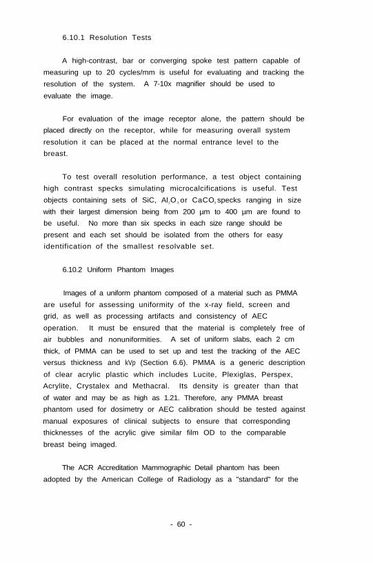
6.10.1 Resolution Tests
A high-contrast, bar or converging spoke test pattern capable of
measuring up to 20 cycles/mm is useful for evaluating and tracking the
resolution of the system. A 7-10x magnifier should be used to
evaluate the image.
For evaluation of the image receptor alone, the pattern should be
placed directly on the receptor, while for measuring overall system
resolution it can be placed at the normal entrance level to the
breast.
To test overall resolution performance, a test object containing
high contrast specks simulating microcalcifications is useful. Test
objects containing sets of SiC, Al2O 3 or CaCO3 specks ranging in size
with their largest dimension being from 200 µm to 400 µm are found to
be useful. No more than six specks in each size range should be
present and each set should be isolated from the others for easy
identification of the smallest resolvable set.
6.10.2 Uniform Phantom Images
Images of a uniform phantom composed of a material such as PMMA
are useful for assessing uniformity of the x-ray field, screen and
grid, as well as processing artifacts and consistency of AEC
operation. It must be ensured that the material is completely free of
air bubbles and nonuniformities. A set of uniform slabs, each 2 cm
thick, of PMMA can be used to set up and test the tracking of the AEC
versus thickness and kVp (Section 6.6). PMMA is a generic description
of clear acrylic plastic which includes Lucite, Plexiglas, Perspex,
Acrylite, Crystalex and Methacral. Its density is greater than that
of water and may be as high as 1.21. Therefore, any PMMA breast
phantom used for dosimetry or AEC calibration should be tested against
manual exposures of clinical subjects to ensure that corresponding
thicknesses of the acrylic give similar film OD to the comparable
breast being imaged.
The ACR Accreditation Mammographic Detail phantom has been
adopted by the American College of Radiology as a "standard" for the
- 60 -
evaluation of image quality of mammographic installations who seek
accreditation by this organization. It can also be used to simulate
the breast in order to verify that proper optical density is obtained
for AEC exposures. This task group recommends the use of a phantom of
equivalent thickness of 4.2 cm PMMA for the determination of patient
exposures. The ACR phantom with an additional 0.36 cm (5/32") PMMA
slab underneath is acceptable for this purpose. For intercomparison
with ACR exposure data. it may also be useful to measure exposures
using the ACR phantom without the added slab (See Section 6.4).
6.10.3 Film-Screen Contact and Uniformity of Speed
A copper mesh or fine screen with about 30-40 lines per inch can
be used to check the uniformity of contact between the screen and the
f i lm. Areas of reduced pressure or dents in the screen will show up
as fuzzy areas of altered optical density and indicate a need for the
replacement of the screen.
The screens should be evaluated for uniformity of speed by
exposing them to a fixed exposure with the uniform phantom and
verifying that all films have densities matching to within ±0.15 OD.
Before performing this test, reproducibility of output must be
verified, as some variation may occur as the tube heats up.
6.10.4 Contrast Measurements
The contrast performance (both subject and photographic contrast)
of the system can be evaluated using a step wedge. The wedge should
provide the imaging system with the full range of exposures
encountered in mammography, but also be reasonably thin to avoid
problems due to oblique projection. A wedge built up of 15 sheets of
type 1100 aluminum of 0.4 mm increments works well for mammographic
imaging. Because of the dominance of photoelectric interactions in
aluminum at these energies, the phantom can provide a sensitive
indication of beam quality variations.
Since aluminum scatters to a lesser degree than breast tissue,
such a phantom is not very useful for assessing anti-scatter
techniques and for this purpose a more tissue-equivalent phantom is
- 61 -
required. A narrow strip or a disc of PMMA of thickness 2-5 mm or a
PMMA stepwedge of 1.5 mm increments attached to the top of a uniform
PMMA phantom 4-5 cm thick yields a low contrast image suitable for
evaluating grid performance, and the effect of varying kVp on
contrast.
The step wedge should be radiographed with the technique used for
the average breast. Two steps in the phantom are identified from the
processed image (Figure 6-2): one which yields a gross optical
density about 1.3 and a second which gives an OD of approximately 1.6.
These steps should be marked and the difference in OD used as an
index of contrast on subsequent tests. The OD of the lower density
step should be used as an index of imaging speed. The 15th step
(6 mm Al) should essentially transmit no radiation and can, therefore,
be used for measurement of the base-plus-fog density.
6.11 Photographic Quality Control (Film-Screen Mammography)
In addition to the material included in this section, excellent
information on processor quality control techniques is available
e lsewhere3 7 , 3 8 .
Variations in both the amount of radiation required to produce a
satisfactory image and also the image contrast frequently result from
changes in the photographic processing. Since this is a chemical
process, it is very sensitive to changes in the concentration of the
chemicals, and the time and temperature of processing. For
satisfactory results these factors must be regulated carefully and
therefore, tests must be set up to monitor the quality and
consistency of photographic processing. Because of the likelihood of
drifts, the tests must be carried out and analyzed on every
operational day of the processor. If drifts are discovered, further
tests should be done in an attempt to determine the cause of the
problem.
Increasing processor development temperature increases film speed
(see Section 3.3.1), but replenishment rates must be adjusted to
compensate for more rapid depletion and oxidation of chemicals.
Furthermore, if processor thermostats are not absolutely reliable at
- 62 -
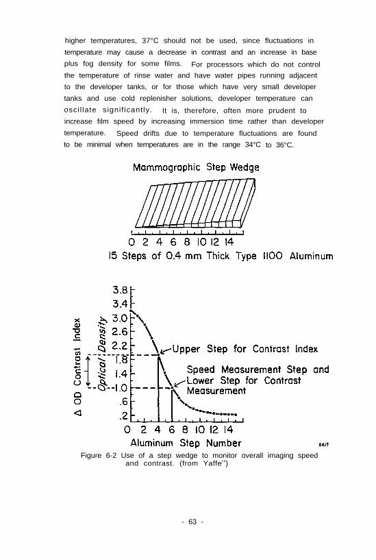
higher temperatures, 37°C should not be used, since fluctuations in
temperature may cause a decrease in contrast and an increase in base
plus fog density for some films. For processors which do not control
the temperature of rinse water and have water pipes running adjacent
to the developer tanks, or for those which have very small developer
tanks and use cold replenisher solutions, developer temperature can
osci l late signif icantly. It is, therefore, often more prudent toincrease film speed by increasing immersion time rather than developer
temperature. Speed drifts due to temperature fluctuations are found
to be minimal when temperatures are in the range 34°C to 36°C.
Figure 6-2 Use of a step wedge to monitor overall imaging speedand contrast. (from Yaffe3 9)
- 63 -
6.11.1 Sensitometry and Densitometry
A sensitometer provides a set of reproducible levels of light
which are used to expose the radiographic film in the darkroom. The
film is then processed at the same time of the day, each operational
day (preferably before patients are imaged, but after the processor
temperature stabilizes). The optical densities (blackness) of the
regions of different light exposure are measured using a densitometer.
The results must be recorded each day in a log book. The same type of
film used for mammography should be used for sensitometric testing. A
box of film should be reserved for this purpose so that tests are
conducted on the same emulsion batch. Occasionally this testing film
should be cross-compared with the batch of film currently used for
imaging patients.
If the sensitometer has a color adjustment, it should be matched
to the color of screen light emission and should expose both emulsions
If double emulsion film is used and only one side of the film if
single emulsion film is used. Because of latent image failure, a
consistent technique should be used for the production of test films
and batches of films should not be exposed in advance to be used
through the week4 0.
The following information should be recorded (see Figure 6-2):
- speed point - This is the optical density under a particular
step on the sensitometric image corresponding to a normal working
density for the film, typically around gross OD of 1.3. The OD of the
same step is recorded in the log book each day.
- contrast index - This is generally taken as the difference in
OD of two steps in the sensitometric image whose densities lie in the
straight-line portion of the characteristic curve of the film.
Convenient points are the step used for the speed index and the step
which yields a density 0.3-0.5 OD greater than the speed point. Once
the steps to be used for the speed and contrast tests have been chosen
they should remain the same for all future tests.
- 64 -
- base-plus-fog index - This is a measurement of the OD of the
film where it has not been exposed to light or x-rays. This provides
an assessment of the amount of film fogging. High values (>0.02 OD
above baseline measurement) may indicate improper film storage,
extremely high processing temperatures, excessively old film or
quality control problems in the manufacture of the film.
A typical log form for recording the results of these
measurements is provided as Figure 6-3. All three indices are
important indicators of image quality and can be used to reveal not
only the existence of problems but in many cases also the reasons for
those problems3 7. The main advantages of the sensitometry technique
are: (a) it is quantitative, (b) it tests the film processing only
and isolates it from other possible factors involved in imaging, and
(c) it provides results instantly which greatly simplifies the
tracking-down of processing problems.
The facility should establish limits of acceptability for variations Of
the speed point, contrast index and base-plus-fog (e.g. Figure 6-3) and
take investigative action when values fall outside those limits.
6.12 Reproducibility and Uniformity
A very useful test of overall imaging performance and consistency
which should be used by all facilities for weekly or more frequent
verification of system performance involves producing a radiograph of
a standard test object or phantom, always using the same technique
factors and image receptor. To provide a contrast scale, the phantom
should incorporate a step wedge or an added 5 mm thick PMMA disc. The
average image density, speed and contrast of the resulting film can be
compared with previous films. This method has been described in
Section 6.10.4. Clearly this method is not able to distinguish between
processing or generator performance faults. If changes are observed
using this technique then it is necessary to use more refined tests to
determine whether processing, the AEC or some other factor, e.g. the
x-ray source or the image receptor, is causing the variation.
A uniform phantom film can be produced by imaging a 4.2 cm
thickness of PMMA to obtain a gross OD around 1.3. Two such films
- 65 -
should be put through the processor, one inserted lengthwise and the
second widthwise. The two films should be identical, demonstrating an
absence of roller marks. The OD of these films should be within
0.20 OD of the standard OD. This will show that mR/mAs, kVp,
filtration and processing speed have not varied significantly. If a
change greater than 0.20 OD is seen, the source of the problem must
be detected and corrected.
6.13 Xeroradiographic Testing
Acceptance and quality control testing of the xeroradiographic
mammography x-ray system is identical to the procedure for film-screen
systems except where noted above and omitting Sections 6.10.3 and
6.11. In addition, the following information is applicable to
xeroradiography.
6.13.1 Processor Adjustments
It is very important that the development voltage and toner
supply rate of the processor are optimized for the beam quality used
by the mammographic facility. If a lower HVL is used for average
breasts, the development bias must be increased. If the development
bias is not increased, the mAs and radiation dose will have to be
significantly increased in order to obtain images of acceptable
quality. With higher HVLs, it is important that the development bias
be decreased in order to increase the edge contrast.
6.13.2 Resolution and Contrast
The evaluation of spatial resolution in xeromammography cannot be
achieved by using conventional high-contrast test targets without
adding absorbers to reduce subject contrast. Such targets will cause
excessive toner migration leading to erroneous values which do not
represent the true resolution of low contrast anatomical features.
The xeroradiographic development process provides an image whose
contrast properties are very different from those of a film-screen
image. The MTF at low spatial frequencies is low so that the system
is relatively insensitive to broad area contrast and, therefore,
- 67 -
displays Considerable exposure and recording latitude. On the other
hand, the system is sensitive to discontinuities (edges) in the
radiation pattern which are enhanced in the processed image.
To assess the ability of the system to image fine detail over a
wide range of breast attenuation, a "latitude phantom" should be used.
Such a phantom is generally wedge-shaped and contains a collection of
both low and high contrast objects in a range of sizes.
6.13.3 Processing
The following reference materials, available from Xerox
Corporation are extremely useful for operation and quality assurance:
Operator's Manual: This manual contains basic information on the
xeroradiographic process, operation of the system and routine
maintenance.
Illustrated Guide to Image Analysis: This guide contains
information on exposure conditions, common image artifacts and
suggestions for their prevention. It can be very helpful for
determining the cause of many problems relating to image quality.
System Plate Management Guide: This guide describes procedures
for the initial installation of the plates, monitoring their quality
and removal from use. A plate management log and a plate reference
list is also included with this guide. The former is used to record
the history of each plate referenced by its serial number and the
latter is used to record any special problems such as artifacts.
Quality Assurance Procedures for the Xeroradiographic Process:
This manual is a useful adjunct to the other reference materials and
can be used as a check list for periodic quality assurance procedures.
Due to the highly specialized nature of the xerographic
technology, special training is strongly recommended for the physicist
or engineer who wishes to become involved in the repair and
maintenance of these systems. The equipment supplier should be
consulted for information on available training.
- 68 -
The appropriate charging and development bias voltages must be
established by the service engineer. The physicist and quality
assurance technologist should review the phantom images using both the
aluminum Xerox phantom and a detail phantom, both described in
Section 6.13.4. After consultation with the radiologist, an
approximate technique should be established. After studies with
patients, a technique chart should be established for varying breast
size (small, medium, large) and composition (fatty, medium and dense).
During routine use, the proper function of the system should be
monitored daily before any mammography is performed by recording an
image of a phantom. The quality of the xeroradiographic plates and
overall conditioner and processor performance should be monitored
weekly by a process called "dark dusting". In this process, all the
available plates are conditioned first and then processed without
exposing them to x-rays. The resulting images should have a uniform
appearance and they should be free from artifacts. Detailed
descriptions of the appearance and origin of typical artifacts have
been published by DeWerd41 and by Xerox Corporation.
6.13.4 Phantoms
The use of some type of breast substitute phantom is highly
recommended for all mammographic facilities. An aluminum wedge
phantom is available from Xerox and it is specifically designed for
xeromammography. This phantom incorporates resolution test targets,
particles simulating microcalcifications, large low contrast "lesions"
and fibers. This phantom is most useful for checking internal
consistency, especially after the processor has been serviced. I t i s
also useful for establishing an approximate exposure technique in a
newly-installed system. Its intended use is only for xeromammography
and it should not be used for the evaluation of film-screen imaging
techniques.
Other phantoms which are made of PMMA and may incorporate test
objects such as large low contrast masses, fibers and Al 2O 3 specks
simulating microcalcifications are also available. The ACR
Accreditation Mammographic Detail Phantom is used widely for
evaluation of both Xerox and film-screen mammography.
- 69 -
7.
1.
2.
3.
4.
5.
9.
10.
11.
12.
13.
14.
15.
16.
REFERENCES
Stanton, L.Ferruci, J.T.
Electrostatic Imaging Systems. In Taveras, J.M. and
Vol. 1, Chap.(eds.). Radiology: Diagnosis/Imaging/Intervention,8, J.B. Lippincott Co., Philadelphia, 1986.
NCRP. Mammography. NCRP Report #85.
Thourson, T.L. and Jeromin, L.S. Electroradiography. InWebster, J.G. Encyclopedia of Medical Devices andInstrumentation, Vol. 2, 1146-1168, Wiley, New York, 1988.ISBN 0-471-62969-3.
Jennings, R.S., et al. Optimal X-ray Spectra for Screen-FilmMammography. Med. Phys. 8: 5, 1981.
Feig, Stephen A. Mammographic Equipment: Principles,features and selection. Radiologic Clinics of North America25: 897-911, 1987.
6. Beaman, S.A. and Lillicrap, S.C. Optimum X-ray Spectra forMammography. Phys. Wed. Biol. 127: 1209, 1982.
7. Kratzat, M. Evaluating the Importance of Focal Spot Sizes inMammography. Medicamundi Vol. 33, no. 2, 1988.
8. NEMA Standards Publication No. XR-5-1990. Measurements ofDimensions of Focal Spots of Diagnostic X-ray Tubes. New York,National Electrical Manufacturers Association.
IEC Standard 336-1982. International Electrotechnical Commission.
Kimme-Smith, C., Bassett, L.W. and Gold, R.H. Focal Spot SizeMeasurements with Pinhole and Slit for Microfocus MammographyUnits. Med. Phys. 15: 298-303, 1988.
Barnes, G.T. and Brezovich, I.A. The Intensity of ScatteredRadiation in Mammography. Radiology 126: 243-247, 1978.
Sickles, E.A. and Weber, W.N. High Contrast Mammography with aMoving Grid: Assessment of Clinical Utility. AJR 146:1137-1139, 1986.
Niklason, L.T., Barnes, G.T. and Rubin, E. MammographyPhototimer Technique Chart. Radiology 157: 539-540, 1985.
White, D.R., Martin, R.J. and Darlison, R. Epoxy Resin BasedTissue Substitutes. BJR 50: 814-821, 1977.
LaFrance, R., Gelskey, D.E. and Barnes, G.T. A M-graphicPhototimer Circuit Modification that Improves Linearity.Radiology 166: 773-776, 1988.
Yaffe, M.J. Physics of Mammography: Image Recording Process.Radiographics 10: 341-363, 1990.
- 70 -
17.
18.
19.
20.
21.
22.
23.
24.
25.
26.
Haus, A.G. Recent Advances in Screen-Film Mammography. InRadiologic Clinics of North America 25: 913-928, 1987.
Nishikawa, R.M. and Yaffe, M.J. Signal-to-Noise Properties ofMammographic Film-Screen Systems. Med. Phys. 12: 32-39, 1985.
Kimme-Smith, C., Bassett, L.W., Gold, R.H., Roe, D. and Orr, J.Mammographic Dual-Screen-Dual Emulsion Film Combination:Visibility of Simulated Microcalcifications and Effect on ImageContrast. Radiology 165: 313-318, 1987.
Oestman, J.W., Kopans, D.B., Linetsky, L., et al. Comparison ofTwo Screen-Film Combinations in Contact and MagnificationMammography: Detectibility of Microcalcifications. Radiology168: 657-659, 1988.
Tabar, L. and Haus, A.G. Processing of Mammographic Films:Technical and Clinical Considerations. Radiology 173: 65-69,1989.
Kimme-Smith, C., Rothschild, P.A., Bassett, L.W., Gold, R.H. andMoler, C. Mammographic film-processor temperature, developmenttime and chemistry: effect on dose, contrast and noise. AJR152: 35-40, 1989.
Frank, E.D., Gray, J.E. and Wilkin, D.A. Flood Replenishment:A New Method of Processor Control. Radiologic Technology 52:271-275, 1980.
Handbook of Glandular Tissue Doses in Mammography. HHS PublicatioFDA 85-8239.
Stanton, L., Villafana, T., Day, J.L. and Lightfoot, D.A. DosageEvaluation in Mammography. Radiology 150: 577-584, 1984.
Conway, B.J. Nationwide Evaluation of X-ray Trends (NEXT),Tabulation and Graphical Summary of Surveys 1984 through 1987.Conference of Radiation Control Programme Directors Inc,Frankfort, Kentucky, 1987.
26a. Conway, B.J. Tabulation and Graphical Summary of 1988Mammography Survey. Conference of Radiation Control ProgrammeDirectors Inc, Frankfort, Kentucky, 1990.
27. Conway, B.J. McCrohan, J.L., Rueter, F.G. and Sulieman, O.H.,Mammography in the Eighties. Accepted for publication inRadiology, 1990.
28. AAPM Task Force Report 14. Performance Specifications andAcceptance Testing for X-ray Generators and Automatic ExposureControl Devices.
- 71 -
29. U.S.A. Food and Drug Administration, HHS. Title 21, Code ofFederal Regulations, Chapter 1, Subchapter J. Part 1020.30 (m)(1 ) ( i ) .
30.
31.
32.
33.
34.
35.
36.
37.
38.
39.
40.
41.
Ibid. Part 1020.31 (f) (3)
Ibid. Part 1020.30 (k)
Ibid. Part 1020.31 (1)
Canada. Radiation Emitting Devices Act, Revised Statutes ofCanada, Chapter 34 (1st Supp.) Radiation Emitting DevicesRegulations, Chapter 1370 Part XII Section 5 (2) (f) (ii).
Ibid. Part XII Section 11 (1) (a) (i + ii)
Ibid. Part XII Section 19 (h)
Ibid. Part XII Section 11 (1) (b)
Goldman, L.W. Radiographic film processing quality assurance:A self-teaching workbook. US Department of Health and HumanServices. HHS Publication, FDA 81-8146. Rockville, Maryland,1981.
Gray, J.E., et al. Quality control in diagnostic imaging.Aspen Publishers Inc., Rockville, Maryland, 1982.
Yaffe, M.J.. Mawdsley, G.E., and Mishikawa, R.H. QualityAssurance in a National Breast Screening Study. Proc SPIE 419:23-30, 1983.
Poznansky, A.K. and Smith, L.A. Practical Problems inProcessing Control. Radiology 90: 135-138, 1968.
DeWerd, L.A. Electroradiography (Xeroradiography): Equipmentand Physical Principles. In Waggener, R.G., Kereiakes, J.G.,and Shalek, R.J. (eds.) Handbook of Medical Physics Vol. 2,p. 123 CRC Press Inc. Boca Raton, Florida. 1984.
- 72 -