Embed Size (px)
Citation preview

Implementing the Monitoring Plan 7-1 May 2000 Equipment Installation and Maintenance
SECTION 7 EQUIPMENT INSTALLATION AND MAINTENANCE
This section provides guidance for the installation and maintenance of stormwater monitoring stations that are equipped with automated monitoring equipment. Automated monitoring stations typically include the following basic elements:
➤ Protective Equipment Enclosures
➤ Power Source
➤ Flow Meter
➤ Automated Sampler
➤ Rain Gauge
➤ Confined Space Entry
➤ Bottle and Equipment Cleaning and Installation
➤➤➤➤ PROTECTIVE EQUIPMENT ENCLOSURES
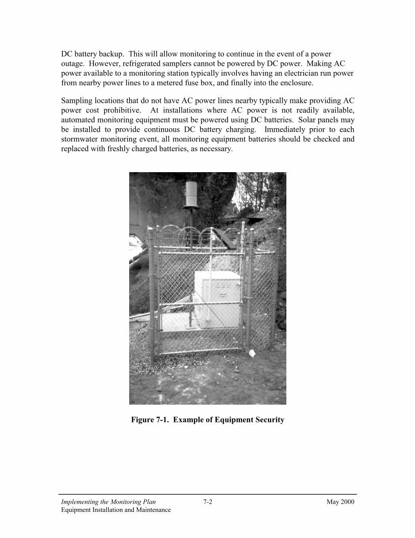
Stormwater monitoring stations containing automated monitoring equipment require a proper protective enclosure that is lockable, resistant to vandalism and tampering, and provides protection from the elements. In areas where equipment tampering may be a concern, the protective enclosures should be surrounded by chain link fencing with a locked gate and razor wire along the top. Figure 7-1 illustrates security for a sampling station equipped with steel enclosure, chain-link fencing, and razor wire.
There are two basic types of enclosures typically used to house monitoring equipment: 1) a heavy gauge steel box with hinged lid, and 2) a walk-in shed type enclosure. The advantages of a walk-in enclosure include shelter for field personnel from rain, more room for field crew to work, and storage for extra sample bottles and equipment. However, walk-in enclosures tend to be more costly than box type enclosures.
The protective enclosure should be secured to a concrete pad, with all wiring and tubing entering/exiting the enclosure routed through appropriately sized conduit. Examples of typical steel box and walk-in monitoring station enclosures are presented in Figures 7-2 and 7-3.
➤➤➤➤ POWER SOURCE
Commercially available automated stormwater monitoring equipment typically has the capability of running on either AC or DC power. At monitoring stations where AC power is available, the preferred setup is to operate the equipment using AC power with
KEY TOPICS
Implementing the Monitoring Plan 7-2 May 2000 Equipment Installation and Maintenance
DC battery backup. This will allow monitoring to continue in the event of a power outage. However, refrigerated samplers cannot be powered by DC power. Making AC power available to a monitoring station typically involves having an electrician run power from nearby power lines to a metered fuse box, and finally into the enclosure.
Sampling locations that do not have AC power lines nearby typically make providing AC power cost prohibitive. At installations where AC power is not readily available, automated monitoring equipment must be powered using DC batteries. Solar panels may be installed to provide continuous DC battery charging. Immediately prior to each stormwater monitoring event, all monitoring equipment batteries should be checked and replaced with freshly charged batteries, as necessary.
Figure 7-1. Example of Equipment Security

Implementing the Monitoring Plan 7-3 May 2000 Equipment Installation and Maintenance
Figure 7-2. Steel Box Monitoring Station Enclosure

Implementing the Monitoring Plan 7-4 May 2000 Equipment Installation and Maintenance
Figure 7-3. Walk-In Monitoring Station Enclosure
(Source: American Sigma, Model 6989)

Implementing the Monitoring Plan 7-5 May 2000 Equipment Installation and Maintenance
➤ FLOW METER
There are two basic types of flow measuring devices typically used for flow weighted stormwater sampling: 1) depth sensors, which convert level measurements to flow rates based on the known pipe or channel geometry and an assumed relationship of depth to flow rate (usually using Manning’s equation – see Figure 5-5), and 2) area velocity measuring devices, which measure both the depth and velocity of flow to produce a more accurate estimation of flow rate. The applicability of flow measuring devices and Manning’s equation are described in detail in Section 5.
Flow monitoring equipment should be installed and maintained according to manufacturer specifications. Flow monitoring equipment should be calibrated, at a minimum, according to manufacturer recommended frequencies. For some applications, more extensive calibration procedures may be required to insure accurate flow measurement.
Installation
The flow meter should be securely fastened to the inside of the protective enclosure in such a way that all controls, display windows, and cable connections are easily accessed. All cables entering/exiting the flow meter should be secured, in a well organized fashion, to the inside of the protective enclosure. This will reduce the potential for accidental disconnection or damage.
The flow monitoring sensor(s) must be installed in the channel, pipe, or flume according to manufacturer specifications. Typically, stainless steel expanding bands are used to mount sensors inside pipes. Sensors may also be mounted at the base of the channel, pipe, or flume using a stainless steel base plate and hardware. The cable(s) that connect the sensor(s) to the flow meter should be housed in conduit from the point at which the cable(s) exits the protective enclosure. Because turbulence can significantly influence flow reading accuracy, placement of the sensor is extremely important. Conveyance pipe segment connecting joints are typical generators of turbulence. Additionally, sensor cables should be secured in such a way as not to create turbulence. Once installed, flow accuracy can be determined by releasing a known quantity of water at varying rates through the conveyance and comparing actual volume released with the volume measured. An example of flow sensor installation in a pipe is shown in Figure 7-4.

Implementing the Monitoring Plan 7-6 May 2000 Equipment Installation and Maintenance
Figure 7-4. Flow Sensor Installation
Maintenance
The flow monitoring equipment should be calibrated according to manufacturer specifications. Flow meters typically contain desiccant packets and moisture indicators to keep the internal components of the equipment dry. The moisture indicators should be checked during each site visit, or at least once between each monitoring event. Often, system malfunctions can be attributed to high moisture levels inside the equipment. Any time a moisture indicator reads above the acceptable level, the desiccant should be replaced with new packets. At a minimum, the sensor(s) should be inspected and calibration checked prior to each monitoring event. The sensor(s) should be calibrated on an as-needed basis. The sensor cable(s) should be inspected at least prior to each stormwater monitoring season. All connections into the flow meter should be visually inspected prior to each monitoring event.
➤➤➤➤ AUTOMATED SAMPLER
The automated sample collection equipment should be installed and maintained according to manufacturer specifications. See Section 5 regarding selection of automated equipment.
Installation
The automated sampler should be installed inside the protective enclosure in such a way that all controls, display windows and cable connections are easily accessed. All wiring should be secured, in a well organized fashion to the inside of the enclosure to prevent

Implementing the Monitoring Plan 7-7 May 2000 Equipment Installation and Maintenance
accidental disconnection or damage. The sampler must be oriented in a way that will allow the sample intake tubing to enter the sampler without sharp bends or kinking, and to allow easy access for tubing replacement (see Figure 7-5).
At the sampler peristaltic pump, where the sample intake tubing is connected to the pump tubing, no metallic fittings or clamps should be used. Using “clean techniques” (Appendix F), the Teflon intake tubing should be inserted (at least a half inch) into the flexible pump tubing and fastened using a non-metallic clamp or cable tie. At no time during this procedure should the ends of the tubing be allowed to touch any object that is not known to be clean (see page 7-10). The flexible pump tubing should then be fed through the peristaltic pump and into the area of the sampler where the sample bottle(s) are housed (see Figure 7-6).
Adequate space must be available in the equipment enclosure to easily remove and replace sample bottles from the automatic sampler.
Proper placement of the sampler intake assures the collection of representative samples. The intake strainer should be placed in the main flow. The vertical position of the intake strainer in the flow is important. Placement at the bottom may result in excess heavy solids and no floating material, while placement at the top may result in excess floating material and no heavy solids. The constituents of interest must be considered when positioning the intake strainer. Placement of the intake strainer is usually at the channel invert, but may be mounted slightly above the invert on one side of the channel wall if high solids loadings are expected. This will reduce the amount of solids that may enter the intake strainer, and help prevent blockages. However, with the intake strainer offset above the channel invert, low flows may not adequately submerge the strainer, thus preventing sample collection.
Maintenance
Using laboratory provided blank water, the automated sampler should be calibrated according to manufacturer specifications to collect the desired sample aliquot. At a minimum, the calibration should be checked prior to each stormwater monitoring season. After each stormwater monitoring event, the sample bottle(s) should be checked to verify that the programmed sample volume was delivered to the sample bottle(s). If the programmed sample volume was not delivered accurately to the sample bottle(s), the automatic sampler should be recalibrated prior to the next monitoring event. Detailed information on the programming of automated equipment is presented in Section 9.

Implementing the Monitoring Plan 7-8 May 2000 Equipment Installation and Maintenance
Figure 7-5. Automated Sampler Installation
Figure 7-6. Pump Tubing Installation

Implementing the Monitoring Plan 7-9 May 2000 Equipment Installation and Maintenance
➤➤➤➤ RAIN GAUGE
Rain gauges should be installed and maintained according to manufacturer specifications. Rain gauges must be installed in a secure fashion in a location where no buildings, trees, overpasses, or other objects obstruct or divert rainfall prior to entering the rain gauge. Additionally, rain gauges must be positioned so that they are level, and maintain that position throughout the study. If an electronic rain gauge is installed, all wiring should be housed in metal conduit from the gauge to the monitoring station enclosure. At a minimum, the rain gauge should be inspected, cleared of debris, and calibrated following manufacturer-specified procedure prior to each stormwater monitoring season. An example of an electronic rain gauge installation is presented in Figure 7-7.
Figure 7-7. Rain Gauge

Implementing the Monitoring Plan 7-10 May 2000 Equipment Installation and Maintenance
➤➤➤➤ CONFINED SPACE ENTRY
The installation and maintenance of stormwater monitoring devices often requires entry into designated confined spaces. At no time during storm conditions, or at any other time when significant flows are present, should any person enter a confined space. Any below-ground-level space that requires entry for equipment installation must be evaluated by personnel trained and certified in confined space entry. Only confined space certified personnel, with proper equipment and training, may enter a confined space. This holds true in the event of an accident. If an accident occurs, do not enter the confined space, but immediately request assistance from confined space certified personnel.
➤➤➤➤ BOTTLE AND EQUIPMENT CLEANING AND INSTALLATION
Prior to each stormwater monitoring event, sample bottles and sampling equipment should be cleaned and installed as specified in the following subsections.
Sample Bottle Cleaning
Prior to each stormwater monitoring event, clean sample bottles must be ordered from the analytical laboratory. Sample bottles must be prepared by the laboratory as specified by analytical method protocols. This includes the addition of sample preservatives where applicable. See Table 12-1 for specific bottle and preservative requirements. Sample preservation is discussed in more detail in Section 10. Specific bottle cleaning procedures are presented in Appendix E. Sample bottles should be stored in a clean environment with lids securely on until the time of use.
Composite Sample Bottle Installation
Clean composite sample bottles should be installed into automated sampling stations using “clean techniques” as described in Section 10 and Appendix F.
Sampling Equipment Cleaning
Any sampling equipment that comes in contact with the sample must be cleaned according to protocols presented in Appendix E. Sampling equipment that most frequently comes in contact with the sample includes pump and sample intake tubing, intake strainers, composite bottle lids, and any grab sampling device, such as a bailer. After cleaning, each clean item should be individually double bagged (sealed in a plastic bag, then sealed in a second plastic bag) and stored until the time of installation or use. The plastic bags used for this purpose must be new and not previously used for any other purpose. Ziplock bags are ideal for this application and are available in a wide variety of sizes.

Implementing the Monitoring Plan 7-11 May 2000 Equipment Installation and Maintenance
Sample Tubing and Intake Strainer Installation
Clean intake and pump tubing should be installed using “clean techniques”, as described in Section 5, 10 and Appendix F, so as not to contaminate the tubing. The tubing should remain double bagged until the time of installation. The clean tubing should have both ends covered with clean, non-metallic, non-contaminating material (i.e. polyethylene caps or clean latex gloves) until the intake strainer is installed at one end and a clean sample bottle is installed at the other end. The tubing ends should be covered with clean latex material to keep the tubing clean during installation, which typically involves feeding the tubing through protective conduit and pipelines. During installation, the intake and pump tubing should only be handled wearing clean, powder-free, nitrile gloves. During installation, the tubing ends should not touch any item not known to be clean. It is important to avoid kinking of the intake tubing during installation, as this will hinder sample collection.
Once the tubing has been installed, the intake strainer should be installed using “clean techniques”. During installation, the strainer should only be handled while wearing clean, powder-free nitrile, gloves. The strainer should be attached to the end of the intake tubing and secured at the designated sampling location. All hardware in the immediate area of the intake strainer (hardware used to secure the suction tubing and intake strainer) must be stainless steel, polyethylene, or Teflon to minimize the possibility of contamination.
Sample Tubing Inspection
The sample intake and pump tubing should be inspected prior to each monitoring event. Intake tubing should be checked for kinks or cracks, and for adequate connection to pump tubing. Tubing clamps or cable ties, which secure the intake tubing to the pump tubing, should also be inspected prior to each monitoring event. Pump tubing should be checked for wear after each monitoring event. Pump tubing will show wear from the peristaltic sample pump. The frequency of pump tubing replacement will vary from site to site, depending primarily on head height, intake tubing length (may range from 3 to 99 feet), and temperature. If pump tubing wear is detected, the tubing should be replaced with new clean tubing prior to the next monitoring event.