Embed Size (px)
Citation preview

SOLUTIONS
Fire Protection
Explosion Protection
Overpressure Protection
Pressure Activation
EQUIPMENT, DESIGN & SERVICE MANUAL
FIRE EXTINGUISHING SYSTEM ENGINEERED FOR USE WITH 3M™ NOVEC™ 1230 FIRE PROTECTION FLUID
DOT / TC CONTAINERS
IMPULSE VALVE OPERATOR (IVO) OR IMPULSE ENERGETIC ACTUATOR (IEA)
UL / ULC LISTINGS FM APPROVAL
NFPA 2001 STANDARD
U.S. & Foreign Patents
Doc. P/N 06-917
Rev. 1 / September, 2019

COPYRIGHT INFORMATION
© Copyright 2019, Fike Corporation. All rights reserved. Printed in the U.S.A.
This document may not be reproduced, in whole or in part, by any means without the prior written consent of Fike. All Fike documentation and hardware are copyrighted with all rights reserved.
TRADEMARKS
Fike, SHP-Pro®, Cheetah® Xi, are registered trademarks of Fike. All other trademarks, trade names or company names referenced herein are the property of their respective owners.
ERRORS AND OMMISSIONS
While every precaution has been taken during the preparation of this document to ensure the accuracy of its content, Fike assumes no responsibility whatsoever for errors or omissions.
Fike reserves the right to change product designs or specifications without obligation and without further notice in accordance with our policy of continuing product and system improvement.
READER QUESTIONS AND RESPONSES
If you have any questions regarding the information contained in this document, or if you have any other inquiries regarding Fike products, please call Fike’s Customer Support Department at (800)-979-FIKE (3453), option 21.
Fike encourages input from our distributors and end users on how we can improve this manual and even the product itself. Please direct all calls of this nature to Fike’s Customer Support Department at (800)-979-FIKE (3453), option 22. Any communication received becomes the property of Fike.
TERMS AND CONDITIONS OF SALE
Because of the many and varied circumstances and extreme condition under which Fike’s products are used, and because Fike has no control over this actual use, Fike makes no warranties based on the contents of this document. FIKE MAKES NO IMPLIED WARRANTIES OF MERCHANTABILITY OR FITNESS FOR A SPECIFIC PURPOSE. Refer to www.fike.com/terms-conditions for Fike’s full TERMS AND CONDITIONS OF SALE.
TERMS OF USE
Do not alter, modify, copy, or otherwise misappropriate any Fike product, whether in whole or in part. Fike assumes no responsibility for any losses incurred by you or third parties arising from such alteration, modification, copy or otherwise misappropriation of Fike products.
Do not use any Fike products for any application for which it is not intended. Fike shall not be in any way liable for any damages or losses incurred by you or third parties arising from the use of any Fike product for which the product is not intended by Fike.
You should install and use the Fike products described in this document within the range specified by Fike, especially with respect to the product application, maximum ratings, operating supply voltage range, installation and other product characteristics. Fike shall have no liability for malfunctions or damages arising out of the use of Fike products beyond such specified ranges.
You should install and use the Fike products described in this document in compliance with all applicable laws, standards, and regulations. Fike assumes no liability for damages or losses occurring as a result of your noncompliance with applicable laws and regulations.
It is the responsibility of the buyer or distributor of Fike products, who distributes, disposes of, or otherwise places the product with a third party, to notify such third party in advance of the contents and conditions set forth in this document. Fike assumes no responsibility for any losses incurred by you or third parties as a result of unauthorized use of Fike products.
QUALITY NOTICE
Fike has maintained ISO 9001 certification since 1996. Prior to shipment, we thoroughly test our products and review our documentation to assure the highest quality in all respects.

Doc. P/N 06-917 Rev. 1 / September, 2019
PAGE / I
TABLE OF CONTENTS
Section Page No.
1. Introduction ................................................................................................................................................................. 1
2. System Components .................................................................................................................................................... 2
2.1. 3M™ Novec™ 1230 Fire Protection Fluid ............................................................................................................. 2
2.2. Agent Storage Containers..................................................................................................................................... 4
2.3. Impulse Valve ....................................................................................................................................................... 6
2.3.1. Valve Recharge Kits .................................................................................................................................... 8
2.4. Pressure Gauge .................................................................................................................................................... 9
2.5. Liquid Level Indicator (LLi) .................................................................................................................................. 10
2.6. Low Pressure Switch (LPS) .................................................................................................................................. 11
2.7. Mounting Straps and Brackets ........................................................................................................................... 12
2.8. Impulse Valve Operator (IVO) ............................................................................................................................ 13
2.9. Impulse Energetic Actuator (IEA) ....................................................................................................................... 14
2.10. Impulse Valve Pneumatic Operator (IVPO) ....................................................................................................... 15
2.11. Impulse Valve Operator Supervisor (IVOS) ....................................................................................................... 16
2.12. Discharge Pressure Switch (DPS) ...................................................................................................................... 17
2.13. Discharge Nozzles ............................................................................................................................................. 18
2.14. Check Valves ..................................................................................................................................................... 19
2.15. Caution/Advisory Signs ..................................................................................................................................... 20
2.16. Nitrogen Actuator Assembly ............................................................................................................................. 22
2.17. UVO Primary Completer Kit .............................................................................................................................. 23
2.18. UEA Primary Completer Kit ............................................................................................................................... 24
2.19. Secondary Completer Kit .................................................................................................................................. 25
2.20. Selector Valve Assembly ................................................................................................................................... 26
2.21. Suppression Disconnect Switch ........................................................................................................................ 28
3. System Design ........................................................................................................................................................... 29
3.1. Evaluate Enclosure Integrity ............................................................................................................................. 29
3.2. Subfloor Protection ........................................................................................................................................... 30
3.3. Determine Hazard Classification ....................................................................................................................... 30
3.4. Determine Enclosure Volume ........................................................................................................................... 30
3.5. Calculate Reduced Volume ............................................................................................................................... 30
3.6. Determine Minimum Design Concentration ..................................................................................................... 31
3.7. Determine Minimum Quantity of Agent Required ........................................................................................... 31
3.8. Apply Altitude Correction Factor ...................................................................................................................... 33

PAGE / II Doc. P/N 06-917 Rev. 1 / September, 2019
TABLE OF CONTENTS
Section Page No.
3.9. Select System Design Concept .......................................................................................................................... 34
3.10. Select System Actuation Method ..................................................................................................................... 35
3.10.1. Single Container with IVO ...................................................................................................................... 35
3.10.2. Multiple Containers with IVOs............................................................................................................... 36
3.10.3. Two Containers with IVO and IVPO ....................................................................................................... 37
3.10.4. Multiple Containers with Single IVO and Multiple IVPOs ...................................................................... 38
3.10.5. Multiple Containers with Primary Nitrogen Actuator ........................................................................... 39
3.10.6. Multiple Containers with Primary and Secondary Actuators ................................................................ 40
3.11. Select Container Fill Range ............................................................................................................................... 41
3.12. Consider Container Manifold Options .............................................................................................................. 41
3.13. Selector Valve Option ....................................................................................................................................... 42
3.14. Determine Container Locations ........................................................................................................................ 43
3.15. Determine Nozzle Quantity and Placement ..................................................................................................... 44
3.15.1. Evaluate Nozzle Area Coverage ............................................................................................................. 45
3.15.2. Evaluate Nozzle Quantity Based on Enclosure Height ........................................................................... 47
3.15.3. Evaluate Elevation Differences Between Pipe Runs .............................................................................. 47
3.15.4. Evaluate Nozzle Discharge Obstructions ............................................................................................... 48
3.16. Determine Piping Layout .................................................................................................................................. 48
3.16.1. Evaluate Minimum Piping Distances ..................................................................................................... 48
3.16.2. Evaluate Tee Split Ratios ....................................................................................................................... 49
3.16.3. Evaluate Tee Orientation ....................................................................................................................... 50
3.17. Estimate Pipe Sizes ........................................................................................................................................... 51
3.18. Apply Tee Design Factor ................................................................................................................................... 52
3.19. Determine the Final Design Quantity Required ................................................................................................ 53
3.20. Determine Design Concentration at Maximum Temperature.......................................................................... 53
3.21. Evaluate Exposure Limitations .......................................................................................................................... 53
3.22. Perform Flow Calculations ................................................................................................................................ 54
3.22.1. Percent Agent in Pipe ............................................................................................................................ 54
3.22.2. Location of First Tee .............................................................................................................................. 54
3.22.3. Liquid Arrival Time ................................................................................................................................. 54
3.22.4. Liquid Runout Time ............................................................................................................................... 55
3.22.5. Nozzle Orifice Area Limitations ............................................................................................................. 55
3.23. Verify System Performance .............................................................................................................................. 55
3.24. Evaluate Selector Valve Pipe Design ................................................................................................................. 55
3.25. Equivalent Length Values ................................................................................................................................. 56

Doc. P/N 06-917 Rev. 1 / September, 2019
PAGE / III
TABLE OF CONTENTS
Section Page No.
4. Installation ................................................................................................................................................................. 57
4.1. Agent Storage Container Floor Loading ............................................................................................................. 57
4.2. Installing Agent Storage Containers ................................................................................................................... 58
4.2.1. Mounting Detail for 5, 10, 20 and 35 lb. (2 , 4, 8.5 and 15 L) Containers ................................................. 58
4.2.2. Mounting Detail for 60 lb. (27 L) Container ............................................................................................. 59
4.2.3. Mounting Detail for 150 lb. (61 L) Container ........................................................................................... 61
4.2.4. Mounting Detail for 100, 215, 375, 650 and 1000 lb. (44, 88, 153, 267 and 423 L) Containers............... 62
4.3. Installing Distribution Piping .............................................................................................................................. 64
4.3.1. Pipe and Fitting Materials ........................................................................................................................ 64
4.3.2. Pipe Size Changes ..................................................................................................................................... 64
4.3.3. General Piping Requirements ................................................................................................................... 64
4.3.4. Manifolds.................................................................................................................................................. 65
4.3.5. Pipe Hangers and Supports ...................................................................................................................... 66
4.3.6. Selector Valves ......................................................................................................................................... 67
4.3.6.1. Selector Valve Activated by Primary Nitrogen Actuator Assembly ................................................ 67
4.3.6.2. Selector Valve Activated by Secondary Nitrogen Actuator Assembly ............................................ 69
4.3.7. Connect Distribution Piping to Container ................................................................................................ 71
4.4. Installing Low Pressure Switch ........................................................................................................................... 73
4.5. Installing Discharge Pressure Switch .................................................................................................................. 74
4.6. Installing Discharge Nozzles ............................................................................................................................... 75
4.7. Installing System Actuation Components .......................................................................................................... 76
4.7.1. Installing Impulse Valve Operator (IVO) ................................................................................................... 76
4.7.1.1. Impulse Valve Operator (IVO) Wiring ............................................................................................. 77
4.7.2. Installing Impulse Energetic Actuator (IEA) .............................................................................................. 77
4.7.2.1. Impulse Energetic Actuator (IEA) Wiring ........................................................................................ 78
4.7.3. Installing Impulse Valve Pneumatic Operator (IVPO) ............................................................................... 78
4.7.4. Installing Impulse Valve Operator Supervisory (IVOS) ............................................................................. 79
4.7.4.1. Impulse Valve Operator Supervisor (IVOS) Wiring ......................................................................... 79
4.7.5. Installing Nitrogen Actuator Assembly ..................................................................................................... 80
4.7.6. Installing UVO Primary Completer Kit ...................................................................................................... 81
4.7.6.1. Universal Valve Operator (UVO) Wiring ......................................................................................... 82

PAGE / IV Doc. P/N 06-917 Rev. 1 / September, 2019
TABLE OF CONTENTS
Section Page No.
4.7.7. Installing UEA Primary Completer Kit....................................................................................................... 83
4.7.7.1. Universal Energetic Actuator (UEA) Wiring .................................................................................... 84
4.7.8. Installing Pneumatic Relay Secondary Completer Kit .............................................................................. 85
4.7.9. Installing Universal Valve Operator Supervisor (UVOS) ........................................................................... 87
4.7.9.1. Universal Valve Operator Supervisor (UVOS) Wiring ..................................................................... 87
4.8. Installing Pneumatic Actuation Lines ................................................................................................................. 88
4.8.1. Two Containers with IVO and IVPO.......................................................................................................... 88
4.8.2. Multiple Containers with IVO and IVPO ................................................................................................... 89
4.8.3. Multiple Containers with Primary Nitrogen Actuator .............................................................................. 90
4.8.4. Multiple Containers with Primary and Secondary Nitrogen Actuators .................................................... 92
5. Acceptance Testing ................................................................................................................................................... 94
5.1. Pre-Checks and Visual Inspections ................................................................................................................... 94
6. Maintenance ............................................................................................................................................................. 96
6.1. Container Recharge Procedure ......................................................................................................................... 98
6.2. Nitrogen Actuator Cylinder Recharge Procedure ............................................................................................. 99
6.3. 3 Inch Check Valve Damper Replacement ........................................................................................................ 99
6.4. IVO, IVPO and UVO Reset Instructions ........................................................................................................... 100
6.5. Selector Valve Reset Procedure ...................................................................................................................... 102
6.6. Pressure Gauge Replacement Procedure ....................................................................................................... 102
Appendix A – Engineered System Design Example ........................................................................................................ 103
Appendix B – Safety Data Sheets ................................................................................................................................... 115
Appendix C – Selector Valve Calculation Example ......................................................................................................... 133
Revision History

Doc. P/N 06-917 Rev. 1 / September, 2019
PAGE / 1
1. INTRODUCTION
The information presented in this manual represents the most up-to-date information available for Fike’s fire
suppression system, engineered for use with 3M™ Novec™ 1230 Fire Protection Fluid. This manual also provides the
information necessary to properly design, install and maintain the fire suppression system using Novec 1230 fluid in
accordance with the requirements of NFPA Standard 2001, Underwriters Laboratories Inc. and FM Approvals.
Enough information is provided in this manual to allow those responsible for designing a Fike fire suppression system
to properly do so, and for the parties responsible for verifying the system design to determine if the design parameters
have in deed been met.
Fike fire suppression systems may be UL/ULC Listed and/or FM Approvals Approved depending on where and how the
system containers where filled. Special codes following the container part number designate which approval your
system has, but the governing indicator is whether the system container labels bear the agency’s official markings.
Systems bearing the UL and ULC mark have been designed, tested and filled per UL 2166,
Halocarbon Clean Agent Extinguishing System Units.
Systems bearing the FM Approved mark have been designed, tested and filled to meet FM 5600,
Approval Standard for Clean Agent Extinguishing Systems.
If any of these marks are absent from the container label, the system containers, while still designed and tested per
relevant UL and FM standards, were not filled at a UL/ULC Listed and/or FM Approved fill location.
Any questions concerning the information presented in this manual should be addressed to:
704 Southwest 10th Street
P.O. Box 610 Blue Springs, Missouri 64013 (U.S.A.)
Phone: (816) 229-3405 Fax: (816) 229-5082
Webpage: www.fike.com

PAGE / 2 Doc. P/N 06-917 Rev. 1 / September, 2019
2. SYSTEM COMPONENTS
2.1. 3M™ Novec™ 1230 Fire Protection Fluid
Novec 1230 fluid is an odorless, colorless, liquefied compressed gas. See Physical Properties for additional information.
It is stored as a liquid and dispensed into the hazard as an electrically non-conductive gaseous vapor (due to its relatively
low boiling point) that is clear and does not obscure vision. It leaves no residue and has acceptable toxicity for use in
occupied spaces at design concentration.
Extinguishing Method
Novec 1230 fluid extinguishes a fire primarily through heat absorption. The gaseous mixture created when Novec 1230
fluid discharges into air has a much higher heat capacity than air alone. The gaseous mixture absorbs large amounts of
heat due to the high heat capacity and extinguishes fires by sufficiently cooling the combustion zone. It is important to
note, Novec 1230 fluid does not use the depletion of oxygen to extinguish a fire.
Approvals
Approvals include, but are not limited to:
Factory Mutual Approved (FM)
Underwriters Laboratories Inc. (UL) Recognized Component
Underwriters Laboratories of Canada (ULC)
US EPA Significant New Alternative Policy (SNAP) report
Use and Limitations
Novec 1230 fluid shall be used on the following class of hazards:
Class A and C hazards including electrical and electronic hazards, telecommunication facilities and high value
assets where the associated down-time would be costly
Class B hazards containing flammable liquids and gases
Novec 1230 fluid shall NOT be used on fire involving the following materials:
Chemicals or mixtures of chemicals capable of rapid oxidation in the absence of air, such as cellulose nitrate and
gunpowder
Reactive metals such as lithium, sodium, potassium, magnesium, titanium, zirconium, uranium and plutonium
Metal hydrides such as sodium hydride and lithium aluminum hydride
Chemicals capable of undergoing auto-thermal decomposition, such as organic peroxides, pyrophoric materials,
and hydrazine
Doc. P/N 06-917 Rev. 1 / September, 2019
PAGE / 3
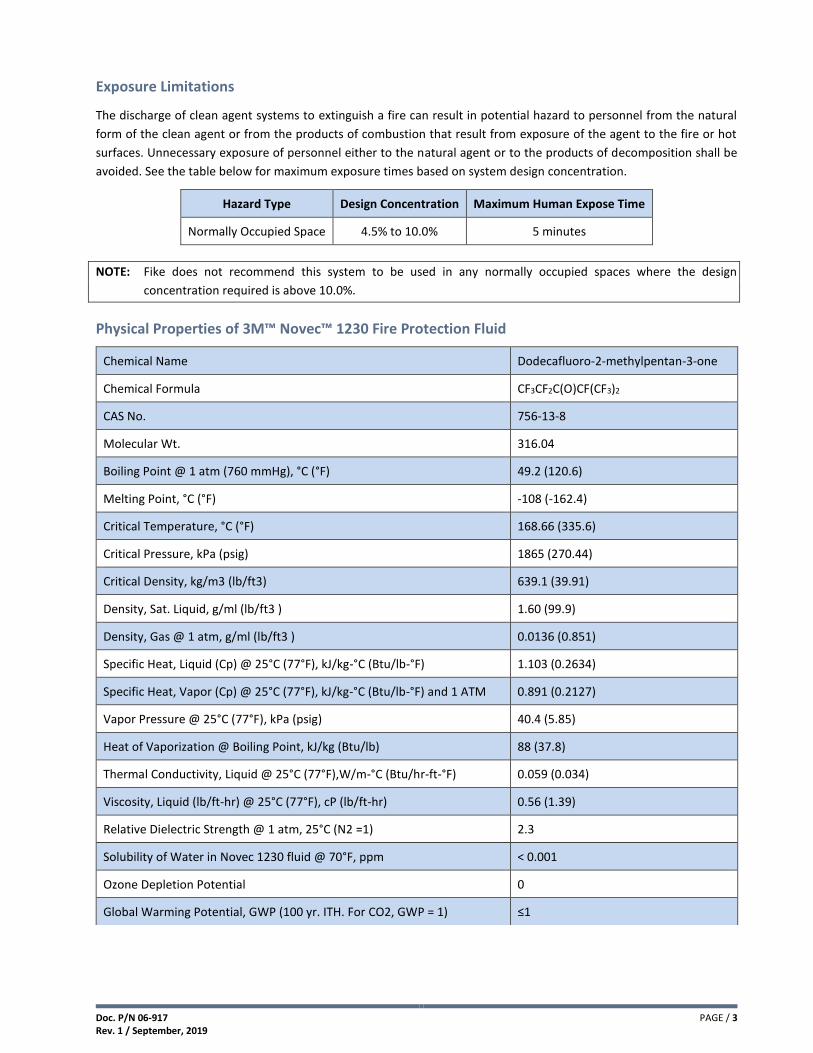
Exposure Limitations
The discharge of clean agent systems to extinguish a fire can result in potential hazard to personnel from the natural
form of the clean agent or from the products of combustion that result from exposure of the agent to the fire or hot
surfaces. Unnecessary exposure of personnel either to the natural agent or to the products of decomposition shall be
avoided. See the table below for maximum exposure times based on system design concentration.
Hazard Type Design Concentration Maximum Human Expose Time
Normally Occupied Space 4.5% to 10.0% 5 minutes
NOTE: Fike does not recommend this system to be used in any normally occupied spaces where the design
concentration required is above 10.0%.
Physical Properties of 3M™ Novec™ 1230 Fire Protection Fluid
Chemical Name Dodecafluoro-2-methylpentan-3-one
Chemical Formula CF3CF2C(O)CF(CF3)2
CAS No. 756-13-8
Molecular Wt. 316.04
Boiling Point @ 1 atm (760 mmHg), °C (°F) 49.2 (120.6)
Melting Point, °C (°F) -108 (-162.4)
Critical Temperature, °C (°F) 168.66 (335.6)
Critical Pressure, kPa (psig) 1865 (270.44)
Critical Density, kg/m3 (lb/ft3) 639.1 (39.91)
Density, Sat. Liquid, g/ml (lb/ft3 ) 1.60 (99.9)
Density, Gas @ 1 atm, g/ml (lb/ft3 ) 0.0136 (0.851)
Specific Heat, Liquid (Cp) @ 25°C (77°F), kJ/kg-°C (Btu/lb-°F) 1.103 (0.2634)
Specific Heat, Vapor (Cp) @ 25°C (77°F), kJ/kg-°C (Btu/lb-°F) and 1 ATM 0.891 (0.2127)
Vapor Pressure @ 25°C (77°F), kPa (psig) 40.4 (5.85)
Heat of Vaporization @ Boiling Point, kJ/kg (Btu/lb) 88 (37.8)
Thermal Conductivity, Liquid @ 25°C (77°F),W/m-°C (Btu/hr-ft-°F) 0.059 (0.034)
Viscosity, Liquid (lb/ft-hr) @ 25°C (77°F), cP (lb/ft-hr) 0.56 (1.39)
Relative Dielectric Strength @ 1 atm, 25°C (N2 =1) 2.3
Solubility of Water in Novec 1230 fluid @ 70°F, ppm < 0.001
Ozone Depletion Potential 0
Global Warming Potential, GWP (100 yr. ITH. For CO2, GWP = 1) ≤1

PAGE / 4 Doc. P/N 06-917 Rev. 1 / September, 2019
2.2. Agent Storage Containers
The agent storage containers are painted steel containers available in various
sizes and varying fill densities. Each container is fitted with an internal siphon
tube, Fike Impulse Valve assembly, pressure gauge, liquid level indicator (LLi),
container nameplate and applicable mounting hardware.
The Impulse Valve contains a fast-acting rupture disc that retains the agent
within the container until the disc is ruptured by an electric or pneumatic
actuator (ordered separately), which allows the agent to be released from the
container.
Each container is factory filled with 3M™ Novec™ 1230 Fire Protection Fluid in 1
lb. (0.5 kg.) increments up to their maximum capacity and is then super-
pressurized with dry nitrogen to 500 psig at 70°F (34.5 bar at 21°C). Fill density
must be specified when ordering. Containers sharing the same manifold must be
equal in size and fill density.
Specifications
Super – Pressurization Level 500 psig at 70°F (34.5 bar at 21°C) after filling with dry nitrogen
Storage Temperature Limitation 32°F (0°C) Minimum to 130°F (54.4°C) Maximum (see note)
Safety Relief Range
If the container pressure reaches 720 to 800 psi (49.6 to 55.2 bar), valve will open
automatically. This fulfills the pressure relief valve requirements in accordance with DOT
regulations.
Container Rating DOT 4BW500 / TC 4BWM534
Actuation Methods Electric / Pneumatic / Manual
Color Options White (default) or Red, Baked Enamel Finish
Fill Increments 1.0 lbs.(0.5 kg)
Fill Range 30 to 70 lbs/ft3 (481 to 1121 kg/m3)
Approvals P/N ending in -3P: UL/ULC Listed and FM Approved
P/N ending in -UL: UL/ULC Listed Only
Note: If container temperature exceeds 130°F (54.5°C), system performance may be affected.
Container Fill Range Tare Weight
(approximate)
Dimensions (approximate) Valve
Size Size Base
P/N
Minimum Maximum Diameter Height
Lb. (L) lbs. (kg) lbs. (kg) lbs. (kg) in. (mm) in. (mm) in.
(mm)
5 (2) 70-357 3 (1.0) 5 (2.0) 11 (5.0) 4.2 (105) 16.2 (411) 1 (25)
10 (4) 70-358 5 (2.5) 10 (4.5) 15 (6.8) 4.2 (105) 27.3 (693) 1 (25)
20 (8.5) 70-359 9 (4.5) 21 (9.5) 19 (8.6) 7.0 (178) 21.7 (551) 1 (25)
35 (15) 70-360 17 (7.5) 38 (17.0) 28 (12.7) 7.0 (178) 32.9 (836) 1 (25)
60 (27) 70-361 30 (13.5) 68 (30.5) 53 (24.0) 10.8 (273) 27.5 (699) 1 (25)
100 (44) 70-362 47 (21.5) 108 (49.0) 77 (34.9) 10.8 (273) 38.8 (986) 1 (25)
150 (61) 70-363 65 (29.5) 150 (68.0) 123 (55.8) 20.0 (508) 23.4 (594) 3 (80)
215 (88) 70-364 93 (42.5) 216 (98.0) 150 (68.0) 20.0 (508) 29.2 (742) 3 (80)
375 (153) 70-365 163 (74.0) 378 (171.5) 216 (98.0) 20.0 (508) 42.4 (1077) 3 (80)
650 (267) 70-366 283 (128.5) 660 (299.0) 364 (165.1) 24.0 (610) 49.7 (1262) 3 (80)
1000 (423) 70-367 449 (203.5) 1045 (474.0) 525 (238.1) 24.0 (610) 71.3 (1811) 3 (80)

Doc. P/N 06-917 Rev. 1 / September, 2019
PAGE / 5
Items Supplied with Container Assembly
Item Number
Description
1 Grooved Coupling & Nipple
2 Impulse Valve
3 Pressure Gauge
4 LLi Boss (see note 1)
5 Liquid Level Indicator (LLi)
6 Nameplate (see note 2)
7 Siphon Tube
8 Mounting Straps & Brackets
NOTES:
1) 100 through 1000 lb. (44 through 423 L) containers are equipped with a LLi Boss.
2) Fike nameplate provides the information that is specific to each container: Assembly and serial number of the container, weight information (tare, gross, and agent), and installation, operation, and safety information. All containers filled either by the factory, or by an Approved Initial Fill Station, are provided with a nameplate bearing the UL and FM markings.
Item 8
Item 6
Item 4
Item 7
Item 3
Item 1
Item 5
Item 2

PAGE / 6 Doc. P/N 06-917 Rev. 1 / September, 2019
2.3. Impulse Valve
The 1" (25 mm) and 3" (80 mm) Impulse Valve Assemblies consists of a
fast-acting rupture disc assembly housed in a brass valve body. The valve
is designed to retain the agent within the container until the disc is
ruptured by an electric or pneumatic actuator (ordered separately)
allowing the agent to be released from the container. The valve is factory
fitted to each clean agent container and is supplied pre-assembled with
a pressure gauge.
The valve’s rupture disc assembly also acts as the pressure relief device
for the container in accordance with DOT regulations by automatically
opening if the container temperature exceeds 130°F (54.4°C).
Each Impulse Valve is equipped with the following ports:
Agent Discharge Port allows agent release from container and also fulfills the pressure relief valve requirements in
accordance with DOT regulations.
Agent Fill Port used to fill (refill) and pressurize the container and also used for the Low Pressure Switch.
Actuator Port used to connect an Impulse Valve Operator (IVO) with Manual Strike Button for electric and manual
actuation of the container or an Impulse Valve Pneumatic Operator (IVPO) for pneumatic operation.
Pressure Gauge Port is used to connect a Pressure Gauge that will monitor internal container pressure, also
equipped with an orifice plug that allows the pressure gauge to be removed safely when the container is
pressurized.
Fill Port
Actuator Port
Rupture Disc Assembly
(Hastelloy C276 disc / 316
SST friction ring)
Fill Port
Pressure Gauge Port
Pressure Gauge Port
Pressure Gauge
Discharge Port
Discharge Port
Impulse Valve

Doc. P/N 06-917 Rev. 1 / September, 2019
PAGE / 7
Internal View – 1" (25 mm) Impulse Valve
Internal View – 3" (80 mm) Impulse Valve
Plug – Fill Port
Valve Core – Fill Port
Valve Core – Fill Port
Plug – Fill Port
Rupture Disc Assembly
Rupture Disc Assembly
Actuator Pin
Actuator Pin

PAGE / 8 Doc. P/N 06-917 Rev. 1 / September, 2019
2.3.1. Valve Recharge Kits
After a system has been discharged, the containers rupture disc valve must be rebuilt before the container can be recharged and placed back into service. The recharge kits below contain all of the items required to rebuild the valve.
1" (25mm) Recharge Kit, P/N 85-049
Item Description Part Number
1 Friction Ring (316 SST) 70-2060
2 Disc Assembly (Hastelloy C276) 70-352
3 O-Ring (Nitrile) 02-11987
4 Valve Core-Fill Port (not shown) 02-4161
5 Reconditioning Instructions (not shown) 06-567
Note: 1" recharge kit is used on 5, 10, 20, 35, 60 and 100 lb. (2, 4, 8, 15, 27 and 44 L) containers.
3" (80mm) Recharge Kit, P/N 85-050
Item Description Part Number
1 Friction Ring (316 SST) 70-2063
2 Disc Assembly (Hastelloy C276) 70-353
3 O-Ring (Nitrile) 02-11989
4 Valve Core-Fill Port (not shown) 02-4161
5 Reconditioning Instructions (not shown) 06-567
Note: 3" recharge kit is used on 150, 215, 375, 650 and 1000 lb. (61,
88, 153, 267 and 423 L) containers
For a detailed procedure on recharging a Fike container with an Impulse Valve refer to Fike’s Recharge Manual, P/N 06-852.
Doc. P/N 06-917 Rev. 1 / September, 2019
PAGE / 9
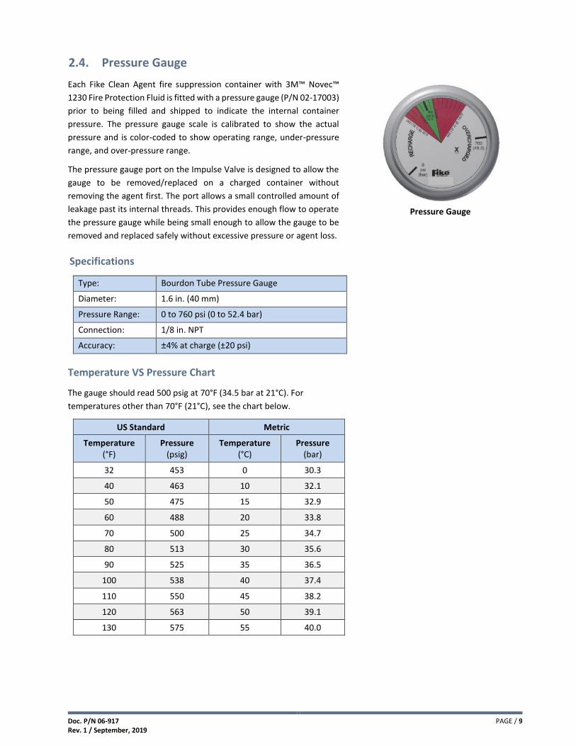
2.4. Pressure Gauge
Each Fike Clean Agent fire suppression container with 3M™ Novec™
1230 Fire Protection Fluid is fitted with a pressure gauge (P/N 02-17003)
prior to being filled and shipped to indicate the internal container
pressure. The pressure gauge scale is calibrated to show the actual
pressure and is color-coded to show operating range, under-pressure
range, and over-pressure range.
The pressure gauge port on the Impulse Valve is designed to allow the
gauge to be removed/replaced on a charged container without
removing the agent first. The port allows a small controlled amount of
leakage past its internal threads. This provides enough flow to operate
the pressure gauge while being small enough to allow the gauge to be
removed and replaced safely without excessive pressure or agent loss.
Specifications
Type: Bourdon Tube Pressure Gauge
Diameter: 1.6 in. (40 mm)
Pressure Range: 0 to 760 psi (0 to 52.4 bar)
Connection: 1/8 in. NPT
Accuracy: ±4% at charge (±20 psi)
Temperature VS Pressure Chart
The gauge should read 500 psig at 70°F (34.5 bar at 21°C). For
temperatures other than 70°F (21°C), see the chart below.
US Standard Metric
Temperature (°F)
Pressure (psig)
Temperature (°C)
Pressure (bar)
32 453 0 30.3
40 463 10 32.1
50 475 15 32.9
60 488 20 33.8
70 500 25 34.7
80 513 30 35.6
90 525 35 36.5
100 538 40 37.4
110 550 45 38.2
120 563 50 39.1
130 575 55 40.0
Pressure Gauge

PAGE / 10 Doc. P/N 06-917 Rev. 1 / September, 2019
2.5. Liquid Level Indicator (LLi)
A Liquid Level Indicator (LLi) device is fitted to every container. The
device is used to measure the level of liquid agent in container without
having to remove the container and weigh it on a calibrated scale. The
agent weight can be determined with the container safely secured in its
installed position. The LLi is factory installed on the 100, 150, 215, 375,
650 and 1000 lb. (44, 61, 88, 153, 267 and 423 L) containers prior to
filling.
The liquid level is found by lifting the measuring tape from inside the
tube to the end above the anticipated liquid level and slowly lowering
the tape until a magnetic interlock with the float is felt. The tape will
then remain in the locked position, allowing a reading to be taken at the
top of the LLi boss. The weight of the agent in the container is
determined by converting the level measurement into a weight
measurement using the tables provided in the Liquid Level Indicator
manual (P/N 06-869).
CONTAINER SIZE
lb. (L)
LLi PART NUMBER
APPROXIMATE LENGTH in. (mm)
100 (44) 70-1353-27 27 (686)
150 (61) 70-1353-14 14 [356)
215 (88) 70-1353-18 18 (457)
375 (153) 70-1353-27 27 (686)
650 (267) 70-1353-38 38 (965)
1000 (423) 70-1353-49 49 (1245)
Specifications
Mounting Thread 1 5/16-12UN-2A NPT
Stem Material Brass
Mounting Material Brass
Float Material Buna-N
Accuracy ±4% at charge (±14 psi)
NOTE: Liquid Level Indicator (LLi) must be installed while the container is empty.
Liquid Level Indicator

Doc. P/N 06-917 Rev. 1 / September, 2019
PAGE / 11
2.6. Low Pressure Switch (LPS)
The Low Pressure Switch (P/N 02-15801) is an optional item that can be
added to Impulse Valve containers for the purpose of continuously
monitoring the container pressure for a low-pressure condition. If the
pressure inside the container drops below 450 psig (31 bar) the LPS contacts
will transfer and invoke a “Supervisory” indication on the control panel.
The LPS may be ordered along with a configured Impulse Valve container or
as a separate item that can be installed on a fully pressurized container
without loss of agent or pressure.
Specifications
Temperature Limits +32°F to +130°F (0°C to 54.4°C)
Enclosure Classification NEMA 4
Contact Rating
Single pole, double throw; 5 amps resistive, 3 amps inductive @ 30 VDC (can be wired for normally open or normally closed operation)
Body Material Aluminum with irridite finish
Weight 6.5 oz (184 g)
Pressure Connection M10 x 1-6G
Electrical Connection 1/2 in. NPT (15 mm)
LPS Length (approximate) 4.375 in. (111 mm) Long (including both connectors)
Wire Leads Thee, 18 gauge x 48 in. (1.2 m) Long Violet (Common), Blue (N.O.), Black (N.C.)
Pressure Setting 450 psig (31 bar), decreasing
Low Pressure Switch (LPS)

PAGE / 12 Doc. P/N 06-917 Rev. 1 / September, 2019
2.7. Mounting Straps and Brackets
The container mounting straps and brackets are constructed of carbon
steel and are designed to rigidly support the installed suppression
containers. Each container is supplied with the appropriate mounting
strap or bracket when ordered.
The straps and brackets must be securely mounted to a rigid surface
with the container resting fully on the floor or vertical surface.
Anchoring into plaster, sheetrock wall or any other facing material is
NOT acceptable. Mounting hardware is supplied by system installer.
Ordering
Part Number
Description
70-2135-X Bracket for 5 lb. (2 L) and 10 lb. (4 L) containers
70-1372-X Bracket for 20 lb. (8.5 L) and 35 lb. (15 L) containers
70-1070-X Bracket for 60 lb. (27 L) container
70-1345-X Strap for 100 lb. (44 L) container
70-2146-X Bracket for 150 lb. (61 L) container
70-1310-X Strap for 215 lb. (88 L) and 375 lb. (153 L) containers
70-1384-X Strap for 650 lb. (267 L) and 1000 lb. (423 L) containers
Notes: 1. -X = paint option. Container brackets can be painted white or
red. When ordering a container bracket the paint option must be specified (-W for white or -R for red).
150 lb. (61 L) Container Bracket
100, 215, 375, 650 and 1000 lb. (44, 88, 153, 267 and 423 L)
Container Strap
5, 10, 20 and 35 lb. (2, 4, 8.5 and 15 L) Container Bracket
60 lb. (27 L) Container Bracket

Doc. P/N 06-917 Rev. 1 / September, 2019
PAGE / 13
2.8. Impulse Valve Operator (IVO)
The Impulse Valve Operator (P/N 02-12728) provides a means to
activate a Fike Impulse Valve container via an electric signal from a Fike
control panel. The IVO can also be manually activated by removing the
safety cotter pin and depressing the red strike button.
Activation of the IVO provides the force required to extend its stainless
steel piston through the base of the actuator where it will impact the
container’s rupture disc valve causing it to open, allowing the agent to
be released from the container. The IVO can easily be reset after
activation to return it to normal operation.
Electrical activation of the IVO requires it to be connected to a Fike
Impulse Releasing Module (P/N 10-2748). The IRM provides the
interface between the IVO and the releasing circuit of the Fike control
panel. Refer to Fike document 06-552 for IRM details.
Connection of the IVO to the container’s actuator port must be
continuously supervised. This is accomplished by using a Fike Impulse
Valve Operator Supervisor (P/N 02-14263) to secure the IVO to the
container’s actuator port. See Section 2.11 for IVOS details.
Specifications
Construction
Stainless Steel Body Brass End Cap
Stainless Steel Piston
Electrical Connection 1/2 in. NPT conduit connection
Wires Two, 20 AWG Black Wires, 36 in. (914 mm) long
Temperature 32 to 130°F (0 to 54.4°C), 93% maximum humidity
Normal Supply Voltage 24 VDC
Current Consumption
(for battery calculations)
0 Amps Standby
0 Amps Active (3 Amp momentary pulse from IRM capacitors)
Ordering Information
The IVO can be ordered separately or it can be ordered as part of the following kit.
IVO Kit (P/N 70-279)
Component P/N Description
02-12728 Impulse Valve Operator (IVO)
02-14263 Impulse Valve Operator Supervisor (IVOS)
10-2748 Impulse Releasing Module (IRM)
02-2213 Security Tie
Impulse Valve Operator (IVO)

PAGE / 14 Doc. P/N 06-917 Rev. 1 / September, 2019
2.9. Impulse Energetic Actuator (IEA)
The Impulse Energetic Actuator (P/N 70-374) provides a means to
activate a Fike Impulse Valve container via an electric signal from a Fike
control panel. Activation of the IEA provides the force required to
extend its stainless steel piston through the base of the actuator where
it will impact the container’s rupture disc valve causing it to open,
allowing the agent to be released from the container. The IEA is a single
shot device that must be replaced after activation.
Electrical activation of the IEA requires it to be connected to a Fike
Impulse Releasing Module (P/N 10-2748). The IRM provides the
interface between the IEA and the releasing circuit of the Fike control
panel. Refer to Fike document 06-552 for IRM details.
Connection of the IEA to the container’s actuator port must be
continuously supervised. This is accomplished by using a Fike Impulse
Valve Operator Supervisor (P/N 02-14263) to secure the IEA to the
container’s actuator port. See Section 2.11 for IVOS details.
Specifications
Construction Brass
Conduit Connection 1/2 in. NPT Male threads
Wires Two, 20 AWG Red Wires, 36 in. (914 mm) long
Normal Supply Voltage 24 VDC
Monitoring Current 0.01 Amps (battery calculations)
Firing Current 1 Amp max.
Auto Ignition Temp. ≥ 170°C (338 °F)
Storage Temp. Min. 5°C (41 °F), max 25°C (77 °F)
Shelf Life 1 year
Service Life (ambient) 10 years
Approvals UL Listed Only
Ordering Information
The IEA can be ordered separately or it can be ordered as part of the following kit.
IEA Kit (P/N 70-390)
Component P/N Description
70-374 Impulse Energetic Actuator (IEA)
02-14263 Impulse Valve Operator Supervisor (IVOS)
10-2748 Impulse Releasing Module (IRM)
Impulse Energetic Actuator (IEA)

Doc. P/N 06-917 Rev. 1 / September, 2019
PAGE / 15
2.10. Impulse Valve Pneumatic Operator (IVPO)
The Impulse Valve Pneumatic Operator (P/N 02-12729) provides a means
to pneumatically activate a Fike Impulse valve container utilizing the
discharge pressure from a Primary Impulse Valve container or Nitrogen
Actuator Assembly.
The pneumatic pressure fed into the IVPO provides the force required to
extend its stainless steel piston through the base of the actuator where
it will impact the container’s rupture disc valve causing it to open,
allowing the agent to be released from the container. The IVPO can be
easily reset after activation to return it to normal operation.
Connection of the IVPO to the container’s actuator port must be
continuously supervised. This is accomplished by using a Fike Impulse
Valve Operator Supervisor (P/N 02-14263) to secure the IVPO to the
container’s actuator port. See Section 2.11 for IVOS details.
Specifications
Construction Stainless Steel Body Brass End Cap Stainless Steel Piston
Temperature 32 to 130°F (0 to 54.4°C) 93% maximum humidity
Pneumatic Connection 1/8 in. NPT, Female
IVPO Limitations
A maximum of 6 containers equipped with IVPOs can be pneumatically activated from an electrically activated Impulse Valve container
Ordering Information
The IVPO can be ordered separately or it can be ordered as part of the following kit.
IVPO Kit (P/N 70-280)
Component P/N Description
02-12729 Impulse Valve Pneumatic Operator (IVPO)
02-4543 1/8 in. NPT x 1/4 in. JIC Adapter
02-4977 1/4 in. JIC x 36 in. (914 mm) Actuation Hose
Impulse Valve Pneumatic
Operator (IVPO)

PAGE / 16 Doc. P/N 06-917 Rev. 1 / September, 2019
2.11. Impulse Valve Operator Supervisor (IVOS)
The Impulse Valve Operator Supervisor (P/N 02-14263) provides the
means to secure and electrically supervise the connection of an
electric actuator or pneumatic operator to the discharge valve on a
Fike Impulse Valve container.
The IVOS has a built-in Form-C push-button switch that supervises the
connection of the electric actuator or pneumatic actuator to the
containers discharge valve. Removal of the IVOS from the discharge
valve will trigger the IVOS switch causing a visual and audible “Trouble
or Supervisory” indication at the Fike control panel signaling that the
container’s actuator has been removed.
Specifications
Construction
− Plastic housing with insert molded SST clip and sealed push-button switch (Form C)
− SST flexible conduit, 0.25 in. (6.4 mm) ID, 33.5 in. (850.9 mm) long
− 3/8 in. electrical connector for 1/2 in. knockout
− 22 AWG wire leads, 44 in. (1117.6 mm) long; Black (NC) / White (NO) / Red (Common)
Temperature 32 to 130°F (0 to 54.4°C), 93% maximum humidity
Ordering Information
The IVOS can be ordered separately or it can be ordered as part of the following kits.
IVO Kit (P/N 70-279)
Component P/N Description
02-12728 Impulse Valve Opeator (IVO)
02-14263 Impulse Valve Operator Supervisor (IVOS)
10-2748 Impulse Releasing Module (IRM)
02-2213 Security Tie
IEA Kit (P/N 70-390)
Component P/N Description
70-374 Impulse Energetic Actuator (IEA)*
02-14263 Impulse Valve Operator Supervisor (IVOS)
10-2748 Impulse Releasing Module (IRM)
*The IEA is UL Listed only.
Impulse Valve Operator
Supervisor (IVOS)

Doc. P/N 06-917 Rev. 1 / September, 2019
PAGE / 17
2.12. Discharge Pressure Switch (DPS)
Discharge Pressure Switch (P/N 02-12534) is used to provide a positive
confirmation to the control system that the Fike fire suppression system has
been discharged manually via the strike button on the Impulse Valve
Operator (IVO) or Nitrogen Actuator. The switch is operated pneumatically
using the agent pressure in the discharge piping network. In response, the
control panel will activate various audio/visual warning devices and auxiliary
relays to notify occupants that the system has been discharged.
Specifications
Temperature Limits 32 to 130°F (0 to 54°C)
Enclosure Classification NEMA 4
Contact Rating Single pole, double throw; 5 amps resistive @ 30 VDC (can be wired for normally open or normally closed operation)
Body Material Aluminum with irridite finish
Pressure Connection 1/4 in. (6 mm) NPT
Approximate Length 4.125 in. (105 mm) (including both connectors)
Electrical Connection 1/2 in. (15 mm) NPT
Wire Leads Three, 18 gauge x 20 in. (508 mm) long
Violet (C), Blue (NO), Black (NC)
Pressure Setting 40 psig (3 bar), increasing
Weight 6.5 oz (184 g)
NOTE: NFPA 2001 requires the installation of a discharge pressure switch on all systems where mechanical system actuation is possible. The discharge pressure switch shall provide an alarm-initiating signal to the releasing panel. The discharge pressure switch can be omitted if the hazard being protected is unoccupiable and is in a remote location where personnel are not normally present.
Discharge Pressure Switch
PAGE / 18 Doc. P/N 06-917 Rev. 1 / September, 2019
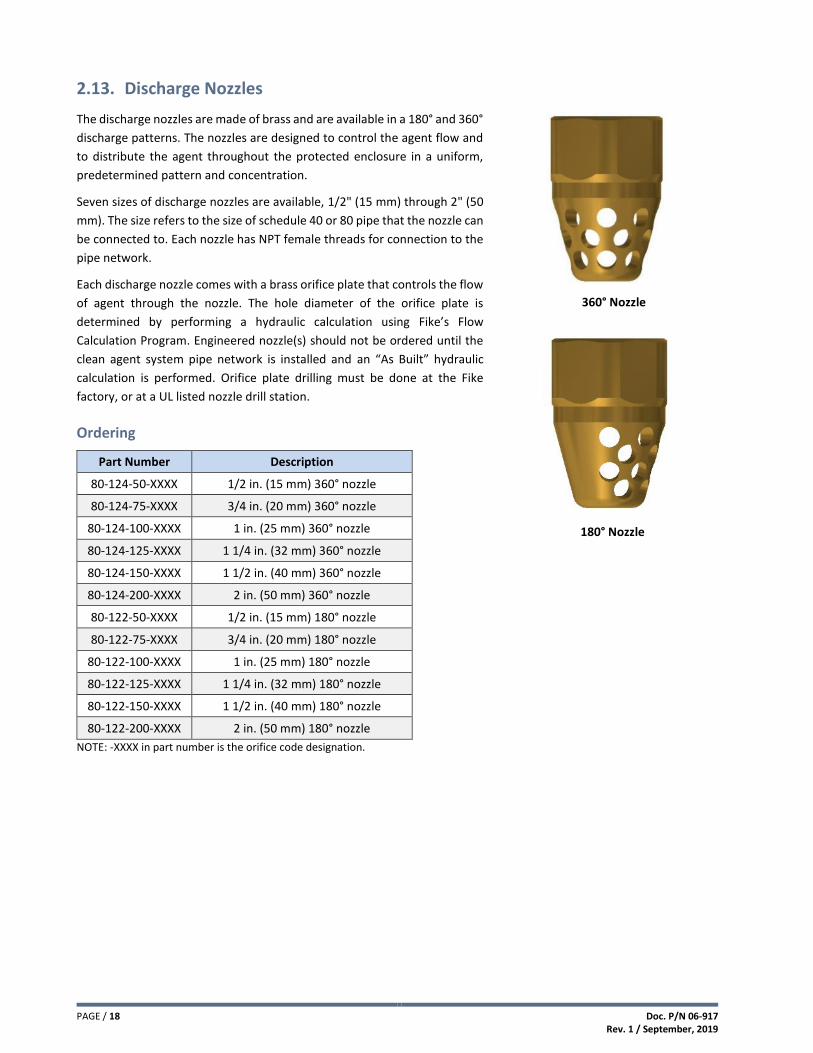
2.13. Discharge Nozzles
The discharge nozzles are made of brass and are available in a 180° and 360°
discharge patterns. The nozzles are designed to control the agent flow and
to distribute the agent throughout the protected enclosure in a uniform,
predetermined pattern and concentration.
Seven sizes of discharge nozzles are available, 1/2" (15 mm) through 2" (50
mm). The size refers to the size of schedule 40 or 80 pipe that the nozzle can
be connected to. Each nozzle has NPT female threads for connection to the
pipe network.
Each discharge nozzle comes with a brass orifice plate that controls the flow
of agent through the nozzle. The hole diameter of the orifice plate is
determined by performing a hydraulic calculation using Fike’s Flow
Calculation Program. Engineered nozzle(s) should not be ordered until the
clean agent system pipe network is installed and an “As Built” hydraulic
calculation is performed. Orifice plate drilling must be done at the Fike
factory, or at a UL listed nozzle drill station.
Ordering
Part Number Description
80-124-50-XXXX 1/2 in. (15 mm) 360° nozzle
80-124-75-XXXX 3/4 in. (20 mm) 360° nozzle
80-124-100-XXXX 1 in. (25 mm) 360° nozzle
80-124-125-XXXX 1 1/4 in. (32 mm) 360° nozzle
80-124-150-XXXX 1 1/2 in. (40 mm) 360° nozzle
80-124-200-XXXX 2 in. (50 mm) 360° nozzle
80-122-50-XXXX 1/2 in. (15 mm) 180° nozzle
80-122-75-XXXX 3/4 in. (20 mm) 180° nozzle
80-122-100-XXXX 1 in. (25 mm) 180° nozzle
80-122-125-XXXX 1 1/4 in. (32 mm) 180° nozzle
80-122-150-XXXX 1 1/2 in. (40 mm) 180° nozzle
80-122-200-XXXX 2 in. (50 mm) 180° nozzle
NOTE: -XXXX in part number is the orifice code designation.
360° Nozzle
180° Nozzle

Doc. P/N 06-917 Rev. 1 / September, 2019
PAGE / 19
2.14. Check Valves
Check Valves are used to prevent agent loss from the open end of a manifold
and/or piping system in the event that one or more containers are removed for
servicing / maintenance.
Check Valves are required for multiple containers connected in a manifold
arrangement and for containers used in a main / reserve system, without the
need for redundant piping systems, to prevent agent loss and reduce the risk of
injury if the system is operated when any containers are removed for
maintenance. All containers must be the same size and same weight.
Images are for reference only. Actual product may vary.
Specifications
Part No. 02-2980-1 02-4158-1 70-317 02-16557 02-16558 70-356
Type Swing Gate
Swing Gate
Swing Gate
Ball Check Ball Check Ball Check
Size 1 in.
(25 mm) 2 in.
(50 mm) 3 in.
(80 mm) 1 in.
(25 mm) 2 in.
(50 mm) 3 in.
(80 mm)
Length (A) 4.3 in.
(108 mm) 6.0 in.
(152 mm) 8.0 in.
(203 mm) 4.2 in.
(107 mm) 6.4 in.
(162 mm) 11.0 in.
(281 mm)
Height (B) 3.6 in.
(91 mm) 4.4 in.
(111 mm) 5.8 in.
(147 mm) 2.8 in.
(70 mm) 1.8 in.
(46 mm) 6.5 in.
(165 mm)
Weight 5 lbs.
(2.3 kg) 13 lbs. (5.9 kg)
28 lbs. (12.7 kg)
5 lbs. (2.3 kg)
16 lbs. (7.3 kg)
37 lbs. (16.8 kg)
Equivalent Length
2.0 ft. (0.61 m)
4.0 ft. (1.22 m)
4.0 ft. (1.22 m)
Sch. 40 15.8 ft.
(4.82 m)
Sch. 40 50.0 ft.
(15.24 m) 14.0 ft. (4.27 m) Sch. 80
10.1 ft. (3.08 m)
Sch. 80 36.6 ft.
(11.16 m)
Material Carbon
Steel Carbon
Steel Ductile
Iron Carbon
Steel Carbon
Steel Ductile
Iron
Ends NPT
Female NPT
Female NPT
Female NPT
Female NPT
Female Grooved
Working Pressure
750 psi (50 bar)
750 psi (50 bar)
750 psi (50 bar)
2000 psi (138 bar)
2000 psi (138 bar)
750 psi (50 bar)
Mounting Horizontal or Vertical (with flow arrow up)
02-2980-1, 02-4158-1 and 70-317 Check Valves
70-356 Check Valve
02-16557 & 02-16558
Check Valves
02-2980-1, 02-4158-1 and 70-317 Check Valves
70-356 Check Valve
02-16557 and 02-16558 Check Valves

PAGE / 20 Doc. P/N 06-917 Rev. 1 / September, 2019
2.15. Caution/Advisory Signs
Instructional signs are used to provide the necessary information to personnel in the area and to comply with NFPA
2001 requirements. The caution lettering and backgrounds meet the requirements of ANSI Z535. The signs are made
from flame retardant, Lexan™ polycarbonate material. Each sign has an adhesive backing mounting purposes. These
signs are an optional item and must be ordered separately.
CAUTION – AREA PROTECTED SIGN (P/N 02-17005)
Provided to alert personnel that the room is protected with a
fire suppression system using 3M™ Novec™ 1230 Fire
Protection Fluid and that they should not enter the area during
or after discharge.
The sign also indicates the requirement that all doors serving
the protected area must be kept closed at all times.
The sign is 13 in. (330 mm) x 10 in. (254 mm), with black
lettering on a yellow background for Caution and black
lettering on a white background for Sign text.
CAUTION – SYSTEM DISCHARGE ALARM SIGN (P/N 02-17006)
Provided to alert personnel that the room is protected with a
fire suppression system using Novec 1230 fluid and to
evacuate the area when the alarms sound.
This sign is provided to also alert personnel that they should
not enter the area when the alarm sounds.
The sign is 9 in. (229 mm) x 6 in. (154 mm), with black lettering
on a yellow background for Caution and black lettering on a
white background for Sign text.
CAUTION – EXIT AREA (P/N 02-17007)
Provided to explain the presence of notification devices that
are located inside the protected space.
This sign explains that a fire suppression system will soon be
discharged if the strobe light is flashing, and appropriate
actions should be taken. This sign should be placed at each
strobe light location.
The sign is 9 in. (229 mm) x 6 in. (154 mm), with black lettering
on a yellow background for Caution and black lettering on a
white background for Sign text.

Doc. P/N 06-917 Rev. 1 / September, 2019
PAGE / 21
NOTICE – MANUAL ACTUATION SIGN (P/N 02-16306)
Provided to inform personnel that the manual release button
on the container cannot be used to activate the container.
Manual release switch(s) located at the hazard exit must be
used to activate the system.
This sign should be placed at each container where the manual
release button on the container has been disabled to prevent
manual activation.
The sign is 13 in. (330 mm) x 10 in. (254 mm), with white
lettering on a blue backgound for NOTICE and black lettering
on a white background for instructional text.
SYSTEM RELEASE SIGN (P/N 02-17008)
Provided to identify each system release station associated
with the fire suppression system. This reduces the risk of a
manual discharge station being mistaken for a fire alarm pull
station.
This sign should be placed at each manual release station
location for positive identification.
This sign is 4 in. (102 mm) x 2.25 in. (57 mm), with red lettering
on a white background.
MAIN / RESERVE SIGN (P/N 02-17009)
Provided to identify each system main/reserve station
associated with the fire suppression system. This sign clearly
identifies the purpose of the switch.
This sign should be placed at each main/reserve station
location for positive identification.
This sign is 4 in. (102 mm) x 2.25 in. (57 mm), with white
lettering on a red background.
SYSTEM ABORT SIGN (P/N 02-17010)
Provided to identify each system abort station associated with
the fire suppression system. This reduces the risk of an abort
station being mistaken for a manual release or fire alarm pull
station.
This sign should be placed at each abort station location for
positive identification.
The sign is 4 in. (102 mm) x 2.25 in. (57 mm), with red lettering
on a white background.
SYSTEM RELEASE
EXTINGUISHING SYSTEM
USING 3M™ NOVEC™ 1230
MAIN / RESERVE
EXTINGUISHING SYSTEM
USING 3M™ NOVEC™ 1230
SYSTEM ABORT
PUSH AND HOLD
EXTINGUISHING SYSTEM
USING 3M™ NOVEC™ 1230
PAGE / 22 Doc. P/N 06-917 Rev. 1 / September, 2019
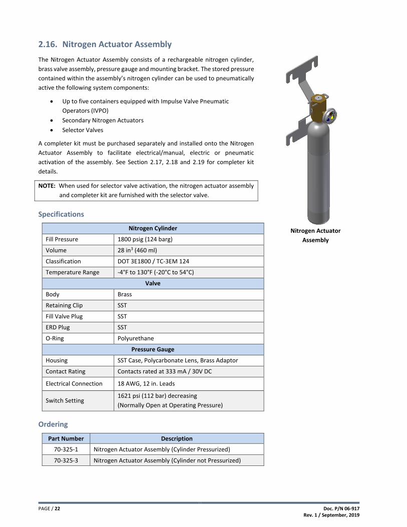
2.16. Nitrogen Actuator Assembly
The Nitrogen Actuator Assembly consists of a rechargeable nitrogen cylinder,
brass valve assembly, pressure gauge and mounting bracket. The stored pressure
contained within the assembly’s nitrogen cylinder can be used to pneumatically
active the following system components:
Up to five containers equipped with Impulse Valve Pneumatic
Operators (IVPO)
Secondary Nitrogen Actuators
Selector Valves
A completer kit must be purchased separately and installed onto the Nitrogen
Actuator Assembly to facilitate electrical/manual, electric or pneumatic
activation of the assembly. See Section 2.17, 2.18 and 2.19 for completer kit
details.
NOTE: When used for selector valve activation, the nitrogen actuator assembly
and completer kit are furnished with the selector valve.
Specifications
Nitrogen Cylinder
Fill Pressure 1800 psig (124 barg)
Volume 28 in3 (460 ml)
Classification DOT 3E1800 / TC-3EM 124
Temperature Range -4°F to 130°F (-20°C to 54°C)
Valve
Body Brass
Retaining Clip SST
Fill Valve Plug SST
ERD Plug SST
O-Ring Polyurethane
Pressure Gauge
Housing SST Case, Polycarbonate Lens, Brass Adaptor
Contact Rating Contacts rated at 333 mA / 30V DC
Electrical Connection 18 AWG, 12 in. Leads
Switch Setting 1621 psi (112 bar) decreasing
(Normally Open at Operating Pressure)
Ordering
Part Number Description
70-325-1 Nitrogen Actuator Assembly (Cylinder Pressurized)
70-325-3 Nitrogen Actuator Assembly (Cylinder not Pressurized)
Nitrogen Actuator
Assembly

Doc. P/N 06-917 Rev. 1 / September, 2019
PAGE / 23
2.17. UVO Primary Completer Kit
The UVO Primary Completer Kit (P/N 70-335) provides a means to electrically
and manually activate the Nitrogen Actuator Assembly. A UVO, included in the
kit, is fitted to the top of the Nitrogen Actuator Assembly. See Section 2.16
The UVO provides a means to electrically activate the Nitrogen Actuator
Assembly via a 24 VDC signal from the Fike control panel and to manually
activate the assembly by pressing the red manual strike button on the UVO.
Activation of the UVO allows pressure from the Nitrogen Actuator Assembly to
flow through a stainless steel pneumatic actuation line to the controlled system
component resulting in activation.
The following parts are included in the UVO Primary Completer Kit. See diagram
below.
Item No.
Part Number Description
1 02-13571 Universal Valve Operator (UVO)
2 02-2213 Security Tie
3 02-13640 1/8 in. NPT x 1/4 in. NPT Adapter
4 C02-1335 1/4 in. NPT Street Tee
5 02-11766 1/4 in. NPT x G1/4 Adapter
6 02-10926 1/4 in. Sealing Washer
7 IG71-026 Vent Valve Assembly
8 02-4530 1/4 in. NPT x 1/4 in. JIC Adapter
9 02-4977 35 in. Hose (1/4 JIC x 1/4 JIC)
10 02-14627 Universal Valve Operator Supervisor (UVOS)
UVO Primary Completer Kit Components
Nitrogen Actuator Assembly
with UVO (Primary)

PAGE / 24 Doc. P/N 06-917 Rev. 1 / September, 2019
2.18. UEA Primary Completer Kit
The UEA Primary Completer Kit (P/N 70-400) provides a means to electrically activate
the Nitrogen Actuator Assembly. A UEA, included in the kit, is fitted to the top of the
Nitrogen Actuator Assembly. See Section 2.16.
The UEA provides a means to electrically activate the Nitrogen Actuator Assembly with
a 24 VDC signal from the Fike control panel. The UEA does not provide a means to
manually activate the Nitrogen Actuator. Activation of the UEA allows pressure from
the Nitrogen Actuator Assembly to flow through a stainless steel pneumatic actuation
line to the controlled system component resulting in activation.
Electrical activation of the UEA requires it to be connected to a Fike Impulse Releasing
Module (P/N 10-2748). The IRM provides the interface between the UEA and the
releasing circuit of the Fike control panel. Refer to Fike document 06-552 for IRM
details.
NOTE: Use of the UEA with the Nitrogen Actuator Assembly is NOT FM approved.
The following parts are included in the UEA Primary Completer Kit. See diagram below.
Item No.
Part Number Description
1 IG71-247 Universal Energetic Actuator (UEA)
2 02-13640 1/8 in. NPT x 1/4 in. NPT Adapter
3 C02-1335 1/4 in. NPT Street Tee
4 02-11766 1/4 in. NPT x G1/4 Adapter
5 02-10926 1/4 in. Sealing Washer
6 IG71-026 Vent Valve Assembly
7 02-4530 1/4 in. NPT x 1/4 in. JIC Adapter
8 02-4977 35 in. Hose (1/4 JIC x 1/4 JIC)
9 02-14627 Universal Valve Operator Supervisor (UVOS)
10 02-11902 1/8 BSPT Plug (not shown)
11 10-2748 Impulse Releasing Module (IRM)
UEA Primary Completer Kit Components
Nitrogen Actuator Assembly
with UEA (Primary)

Doc. P/N 06-917 Rev. 1 / September, 2019
PAGE / 25
2.19. Secondary Completer Kit
The Secondary Completer Kit (P/N 70-336) provides a means to pneumatically
activate the Nitrogen Actuator Assembly. See Section 2.16. A Pneumatic Relay,
included in the kit, is fitted to the top of the Nitrogen Actuator Assembly.
Pressure from a ‘Primary’ Nitrogen Actuator Assembly (See Section 2.17 and
2.18) is used to activate the Pneumatic Relay, which allows pressure from the
Nitrogen Actuator Assembly to flow through a stainless steel pneumatic
actuation line to the controlled system component resulting in activation.
Multiple Nitrogen Actuator Assemblies with Secondary Completer Kits can be
daisy chained together to increase the allowable length of the pneumatic
actuation line. The Pneumatic Relay does not provide a means to manually
activate the Nitrogen Actuator Assembly.
The following components are included in the Secondary Completer Kit. See
diagram below.
Item No.
Part Number Description
1A* IG71-120 Pneumatic Relay
1B* 02-11243 1/8 in. x 1/4 in. JIC Hex Nipple
1C* 02-4977 1/4 in. JIC x 1/4 in. JIC Braided Hose, 36 in. long
2 02-14721 1/4 in. JIC x 1/4 in. FNPT Branch Tee
3 02-11766 1/4 in. NPT x G1/4 Adapter
4 02-10926 1/4 in. Sealing Washer
5 IG71-026 Vent Valve Assembly
6 02-11346 1/4 in. JIC Coupling
*Part of pneumatic relay assembly (P/N 70-334)
Secondary Completer Kit Components
Nitrogen Actuator Assembly
with Pneumatic Relay
(Secondary)

PAGE / 26 Doc. P/N 06-917 Rev. 1 / September, 2019
2.20. Selector Valve Assembly
Selector Valves allow a single agent supply to be utilized for protection of
multiple hazards of similar volume by directing the flow of agent into one
specific hazard. This reduces the total amount of agent required to protect
multiple hazards. Selector valve systems can only be used to protect one hazard
at a time and will not be effective if two or more hazards are involved in a fire
simultaneously.
Selector valves are closed during normal operation, blocking the flow of agent
through the piping network. A nitrogen actuator with compatible actuator
must be installed and connected to each selector valve actuator via a stainless
steel pilot line connection. This connection allows the pressure from the
nitrogen actuator to be delivered to the selector valve actuator for valve
activation. After activation, the selector valve must be manually closed (reset).
Specifications
Valve
Standard Port Ball Valve NPT Threads Body: Carbon Steel or Stainless Steel Ball: Stainless Steel Pressure Rating: 1 in. (25 mm) = 2000 psi (138 bar)
All others = 1500 psi (103 bar)
Actuator Rack and Pinion Pneumatic Actuator, ¼ turn, Double Acting Pressure Rating: 80 – 142 psi (5.5 – 9.8 bar) Factory Installed on Ball Valve
Pop-Off Valve
1/4 in. NPT ASME Relief Valve for Air or Gas Service Set Pressure: 100 psi (6.9 bar) Relief Capacity: 92 SCFM Body, Nozzle, Stem and Spring Material: Stainless Steel Seat Material: Silicone Conforms to ASME Section VIII Pressure Vessel Code
Ordering
The base selector valve can be ordered seperately for replacement purposes as identified in the following table.
Part Number Description
02-15708-10 Selector Valve, Carbon Steel, 1 in. NPT
02-15708-15 Selector Valve, Carbon Steel, 1.5 in. NPT
02-15708-20 Selector Valve, Carbon Steel, 2 in. NPT
02-15708-30 Selector Valve, Carbon Steel, 3 in. NPT
02-15708-40* Selector Valve, Carbon Steel, 4 in. NPT
02-15709-10 Selector Valve, Stainless Steel, 1 in. NPT
02-15709-15 Selector Valve, Stainless Steel, 1.5 in. NPT
02-15709-20 Selector Valve, Stainless Steel, 2 in. NPT
02-15709-30 Selector Valve, Stainless Steel, 3 in. NPT
02-15709-40* Selector Valve, Stainless Steel, 4 in. NPT
*Selector valve is not UL Listed or FM Approved.
Selector Valve Assembly
(Actuation Components not Shown)

Doc. P/N 06-917 Rev. 1 / September, 2019
PAGE / 27
Selector Valve Assembly Ordering Format
The following ordering format must be used to order the selector valve as part of an assembly that includes the components required to install and activate the valve.
Part Number: 70-396-XX-XXX A BCD
A = 10 – 1 in. NPT (25 mm) 15 – 1-1/2 in. NPT (40 mm) 20 – 2 in. NPT (50 mm) 30 – 3 in. NPT (80 mm) 40 – 4 in. NPT (100 mm)
B = C – Carbon Steel Body S – Stainless Steel Body
C = D – UVO Completer Kit S – Pneumatic Relay Completer Kit M – UEA Completer Kit
D = F – Nitrogen Actuator Assembly (Filled) U – Nitrogen Actuator Assembly (Unfilled)
Each selector valve assembly may include the following parts depending upon the part number ordered.
Part Number Description Notes
02-15708-XX-CX Carbon Steel Selector Valve Valve material supplied is based on selector valve assembly part number. 02-15709-XX-SX Stainless Steel Selector Valve
70-325-X Nitrogen Actuator Assembly X indicates filled (1) or unfilled (3)
70-335 Universal Valve Operator (UVO) Primary Completer Kit Completer kit furnished is based on selector valve assembly part number.
70-336 Pneumatic Relay Secondary Completer Kit
70-400 Universal Energetic Actuator (UEA) Primary Completer Kit
Dimension and Weight Information
Part Number Size In.
(mm) Type
A B C D Wt. lb.
(kg.) In. (mm)
70-396-10-XXX 1
(25) Threaded
3.4 (86)
1.7 (43)
7.6 (192)
3.7 (95)
7.8 (3.5)
70-396-15-XXX 1 ½ (40)
Threaded 4.4
(111) 2.2 (55)
8.5 (217)
4.1 (104)
11.8 (5.3)
70-396-20-XXX 2
(50) Threaded
5.5 (140)
2.8 (70)
9.7 (247)
4.5 (115)
16.7 (7.6)
70-396-30-XXX 3
(80) Threaded
6.8 (171)
3.4 (86)
8.8 (234)
5.0 (127)
30.1 (13.7)
70-396-40-XXX* 4
(100) Threaded
9.1 (231)
4.6 (116)
10.6 (269)
6.5 (165)
69.8 (31.7)
*Selector valve is not UL Listed or FM Approved.

PAGE / 28 Doc. P/N 06-917 Rev. 1 / September, 2019
2.21. Suppression Disconnect Switch
The Suppression Disconnect Switch is used to electrically isolate the releasing device
from the associated control panel’s releasing circuit. This allows work to be
performed in the area protected by the suppression system or on the suppression
system itself without the potential for accidental discharge.
The assembly consists of a stainless steel faceplate with etched black text, two-
position keyed switch, and normally open and/or normally closed contact blocks. The
switch key can only be removed in the ARMED position.
The assembly can be ordered with or without status LEDs (Green – ARMED and Red
– DISARMED). The LEDs provide positive indication of the status of the releasing
circuit. LEDs require 24 VDC auxiliary power from the associated control panel for
operation.
Refer to Fike document 06-472 for switch installation instructions.
NOTE: NFPA requires that a listed disconnect switch be installed on all electrically activated suppression systems to
prevent false discharges when the system is being tested or serviced. Upon activation, the switch shall cause a
supervisory signal at the control panel.
Specifications
Input Voltage 15 – 30 VDC
Current 0 mA (no LEDs) / 13.1 mA (LED active)
Circuit Limitations Class B only
Contact Ratings 8A @ 24 VDC resistive / 4A @ 24 VDC inductive
Operating Temperature 32 to 120°F (0 to 49°C)
Operating Humidity 93% RH
Weight 0.55 lb. (0.25 kg)
Dimensions (LxH) 4.50 in. x 4.5 in. (114.4 mm x 114.4 mm)
Ordering
Part Number Description
10-2698 Suppression Disconnect Switch, no LEDs
10-2699 Suppression Disconnect Switch, with LEDs
02-2153 Two-gang masonry box, 2.5 in. deep (RACO 691 or equal) used with 10-2698 switch
02-11881 Two-gang masonry box, 3 in. deep (RACO 696 or equal) used with 10-2699 switch
Spare Parts
Part Number Description Part Number Description
02-12294 Double contact block (2 NC) 02-12315 3 block switch
02-12295 Double contact block (2 NO) 02-12316 Single contact block (NC)
02-12296 Replacement keys 02-12318 Locking ring wrench
02-12298 5 block switch 10-2714 Cover plate, no LED holes
02-12300 Single contact block (NO) - -
Disconnect Switch with LEDs

Doc. P/N 06-917 Rev. 1 / September, 2019
PAGE / 29
3. SYSTEM DESIGN
The following is a summary of the steps necessary to design a Fike Fire Suppression System using 3M™ Novec™ 1230
Fire Protection Fluid within the limitations established by Fike’s UL / ULC listing, FM approval and in compliance with
NFPA 2001.
3.1. Evaluate Enclosure Integrity
When designing a total flooding fire suppression system using Novec 1230 fluid, the integrity of the protected
enclosure(s) shall be considered. Integrity refers to the ability of the enclosure to retain the discharged Novec 1230
fluid. For a total flooding suppression system to be effective, the design concentration must be achieved and then
maintained for at least ten minutes or for a period of time that is sufficient for emergency personnel to respond, as
determined by the Authority Having Jurisdiction (AHJ).
The general guidelines for maintaining room integrity are as follows:
1. Doors - All doors entering and/or existing from the perimeter of the protected space(s) should have drop seals on
the bottom, weather-stripping around the jams, latching mechanisms and door closure hardware. In addition,
double doors should have a weather-stripped astragal to prevent leakage between doors and a coordinator to
assure the proper sequence of closure. Doors that cannot be kept normally closed shall be equipped with door
closure hardware and magnetic door holders that will release the door(s) prior to system discharge.
2. Ductwork - All ductwork leading into or out of the protected space(s) should be isolated with sealed “low smoke”
dampers. Dampers should be spring loaded or motor operated to provide 100% air shutoff upon activation to
ensure an adequate seal and prevent leakage.
3. Air Handling/Ventilation - Forced air ventilation systems, others than those necessary to ensure safety, shall be shut
down or closed automatically where their continued operation would adversely affect the performance of the fire
extinguishing system or result in propagation of the fire. Self-contained air recirculation systems, if not shut down
or closed automatically, shall have the volume of the associated ductwork and components mounted below the
ceiling height of the protected space considered as part of the total hazard volume when determining the quantity
of agent.
4. Penetrations - To prevent the loss of agent through openings to adjacent hazards or work areas, openings (e.g.,
holes, cracks, gaps, pipe chases, cable trays, floor drains, etc.) shall be permanently sealed or equipped with
automatic closures. Floor drains should be equipped with traps filled with non-evaporating product to prevent
leakage.
5. Walls Construction - All perimeter walls of the protected space(s) that define the hazard should extend slab-to-slab
and each should be sealed at the top and bottom on the interior side. Where walls do not extend slab-to-slab,
bulkheads will have to be installed to achieve the desired sealing characteristics. Porous block walls must be sealed
to prevent agent leakage through the wall.
6. Pressurization – The protected enclosure(s) shall have the structural strength and integrity necessary to contain the
agent discharge. The designer shall take into consideration the pressures developed by the agent discharge into the
enclosure and determine if venting is required to prevent excessive pressures that could present a threat to the
structure strength of the enclosure.
At the discretion of the AHJ, a room integrity fan pressurization test may be required to determine how long the
protected enclosure will hold the agent after a discharge. The room integrity fan pressurization test must be performed
in accordance with the equipment manufacturer’s requirements and NFPA 2001, Annex C.
Where reasonable confinement of the agent discharge is not achievable or practical, protection shall be expanded to
include the adjacent connected hazards or work areas.

PAGE / 30 Doc. P/N 06-917 Rev. 1 / September, 2019
3.2. Subfloor Protection
Where the system is being installed to protect a room with a raised or sunken floor, the room and the raised floor shall
be simultaneously protected. 3M™ Novec™ 1230 Fire Protection Fluid shall not be used to provide total flooding
protection of a raised floor area only. Where a room and raised or sunken floor is to be protected by a total flooding
system, each area shall be provided with detectors, piping network, and nozzles.
3.3. Determine Hazard Classification
Hazard classification generally falls into one of the three following categories and sometimes a combination thereof.
The hazard classification for each protected hazard must be determined in order to select the correct minimum design
concentration for determining agent quantity.
Class A Fires involving ordinary combustible materials, such as wood, cloth, paper, rubber and many plastics (i.e.,
anything that leaves an ash residue after combustion).
Class B Fires involving flammable liquids, combustible liquids, petroleum greases, tars, oils, oil-based paints,
solvents, lacquers, alcohols, and flammable gases.
Class C Fires involving energized electrical equipment.
3.4. Determine Enclosure Volume
The volume of each hazard to be protected must be calculated by multiply the enclosure length times the enclosure
width to determine the area, and then multiply the area times the enclosure height to determine the volume for each
hazard area. If any area is an odd shape, it may need to be divided up into regular shapes that will allow volume
calculations. Then, total all of the volumes together to determine the actual volume of the entire area to be protected.
If the odd shape of the area will affect the distribution of agent, it may be best to calculate sections of the hazard as
separate areas and include nozzles for each of these areas. Volumes that are open to the area being protected (e.g.,
non-dampered ductwork, uncloseable openings, etc.) must be added to the calculated volume.
If the ceiling height exceeds the maximum allowable ceiling height allowed for the nozzle selected, multiple levels of
nozzles must be designed into the system. In this case, it is usually beneficial to treat each level as a separate protected
area so that proper agent distribution is achieved.
3.5. Calculate Reduced Volume
As a general rule, the enclosure volume should be based on the empty (gross) volume. However, the volume of solid,
non-permeable objects in each hazard area that are not removable can be deducted from the volume of the hazard.
This includes columns, beams, normally closed closets, ducts that pass completely through the hazard area without any
openings, and any other permanently fixed objects that cannot be removed from the hazard enclosure. Any object that
can be removed from the hazard area CANNOT be deducted from the total hazard volume.
Calculate the volume of all solid, permanent objects and add them together for each hazard area to determine the
volume that can be deducted from the total volume of the hazard area. Subtract the Solid Object Volume from the Total
Volume to determine the Reduced Volume.

Doc. P/N 06-917 Rev. 1 / September, 2019
PAGE / 31
3.6. Determine Minimum Design Concentration
Minimum Design Concentration is defined by NFPA 2001 as the extinguishing concentration for the specific fuel plus a
20% safety factor for Class A fuel. Extinguishing Concentration is the agent concentration required to extinguish a test
fire.
Using the Hazard Classification (Class A, B or C) determined for each protected hazard, use the following table to
determine the minimum design concentration that must be used for a particular hazard.
Hazard Classification
Minimum Design Concentration
NOTES
Class A 4.5% Clean Agent System incorporates Detection & Control System to automatically discharge agent.
Class A 4.7% Recommendation, when protecting multiple hazards w/ single agent supply.
Class C 4.5% When energized electrical hazard remains powered during/after agent discharge and Clean Agent System incorporates Detection & Control System to automatically discharge agent.
Class C 4.7% Recommendation, when protecting multiple hazards w/ single agent supply.
Class B (Heptane)
5.85% For design concentrations of other Class B (flammable liquids), consult Fike’s Product Support group.
NOTES:
1. When 3M™ Novec™ 1230 Fire Protection Fluid is used in a “Normally Occupied” area, a maximum design concentration of 10.0% is allowed.
2. Concentrations greater than 10.0% can only be used in unoccupied areas.
3. See Section 3.21 for Exposure Limitations.
3.7. Determine Minimum Quantity of Agent Required
To determine the minimum quantity of agent required, determine the minimum design temperature for each hazard
being protected and determine the minimum design concentration required for the material to be extinguished.
Minimum design temperature is defined as the minimum anticipated temperature in the enclosure during normal
conditions and is usually determined by the environmental conditions or the air handling system. This temperature is
used in the design because it typically represents the worst case scenario, requiring the highest amount of agent.
Plug the temperature and design concentration values into the following formula to determine the minimum design
quantity of agent required for the hazard. The amount of agent in the system must always be at least this much and
may be exceeded. Failure to supply the minimum amount of agent calculated may inhibit the system from suppressing
a fire.
The minimum design quantity of agent needed can be determined using the following formula:
Where: W = Quantity of agent [lbs. (kg)]
V = net volume of hazard, calculated as the gross volume minus the volume of fixed structures impervious to clean agent vapor [ft3 (m3)]
C = agent design concentration [vol%]
S = specific volume of superheated agent vapor at 1 atm and the minimum anticipated temperature [°F (°C)] of the protected volume [ft3/lb (m3/kg)]

PAGE / 32 Doc. P/N 06-917 Rev. 1 / September, 2019
The second option for calculating the minimum quantity of agent required is to use the Flooding Factors Table below.
To use these tables, start by locating the Minimum Design Temperature in the left column, follow this line across until
you reach the column for the Minimum Design Concentration needed for the design. The number listed in the cell where
the temperature line and concentration column meet is the Flooding Factor to be used.
To determine the minimum quantity of agent required, multiply the hazard volume by the Flooding Factor determined
from the tables below. Repeat this step for each area protected by the system.
FLOODING FACTORS – Agent vs. Temperature Charts (English Units)
Temp.
(t)
(°F)c
Specific Vapor
Volume(s)
(ft3/lb)d
Weight Requirements of Hazard Volume, W/V (lb/ft3)b
(English Units)
3M™ Novec™ 1230 Fire Protection Fluid Design Concentration (% by Volume)e
4.5 4.7 5.0 6.0 7.0 8.0 9.0 10.0
30 1.05883 0.0445 0.0466 0.0497 0.0603 0.0711 0.0821 0.0934 0.1049
40 1.08324 0.0435 0.0455 0.0486 0.0589 0.0695 0.0803 0.0913 0.1026
50 1.10765 0.0425 0.0445 0.0475 0.0576 0.0680 0.0785 0.0893 0.1003
60 1.13206 0.0416 0.0436 0.0465 0.0564 0.0665 0.0768 0.0874 0.0981
70 1.15647 0.0407 0.0426 0.0455 0.0552 0.0651 0.0752 0.0855 0.0961
80 1.18088 0.0399 0.0418 0.0446 0.0541 0.0637 0.0736 0.0838 0.0941
90 1.20529 0.0391 0.0409 0.0437 0.0530 0.0624 0.0721 0.0821 0.0922
100 1.22970 0.0383 0.0401 0.0428 0.0519 0.0612 0.0707 0.0804 0.0904
110 1.25411 0.0376 0.0393 0.0420 0.0509 0.0600 0.0693 0.0789 0.0886
120 1.27852 0.0369 0.0386 0.0412 0.0499 0.0589 0.0680 0.0774 0.0869
130 1.30293 0.0362 0.0379 0.0404 0.0490 0.0578 0.0667 0.0759 0.0853
a The manufacturer’s listing specifies the temperature range for operation. b W/V [agent weight requirements (lb/ft3) or (kg/m3)] = pounds of agent required per ft3 (m3) of protected volume needed to produce the
indicated concentration at the temperature specified. c t [temperature (°F) or (°C)] = the design temperature in the hazard area. d s [specific volume (ft3/lb)] = specific volume of superheated Novec 1230 fluid as approximated by the formula: s = 0.9856 + 0.002441(t)
s [specific volume (m3/kg)] = specific volume of superheated Novec 1230 fluid as approximated by the formula: s = 0.0664 + 0.0002741(t) e c [concentration (%)] = volumetric concentration of Novec 1230 fluid in air at the temperature indicated.
FLOODING FACTORS – Agent vs. Temperature Charts (Metric Units)
Temp.
(t)
(°C)c
Specific Vapor
Volume(s)
(m3/kg)d
Weight Requirements of Hazard Volume, W/V (kg/m3)b
(Metric Units)
3M™ Novec™ 1230 Fire Protection Fluid Design Concentration (% by Volume)e
4.5 4.7 5.0 6.0 7.0 8.0 9.0 10.0
0 0.0664000 0.7096 0.7427 0.7926 0.9613 1.1336 1.3096 1.4895 1.6734
5 0.0677715 0.6953 0.7277 0.7766 0.9418 1.1106 1.2831 1.4593 1.6395
10 0.0691430 0.6815 0.7133 0.7612 0.9232 1.0886 1.2576 1.4304 1.6070
15 0.0705145 0.6682 0.6994 0.7464 0.9052 1.0674 1.2332 1.4026 1.5757
20 0.0718860 0.6555 0.6861 0.7322 0.8879 1.0471 1.2096 1.3758 1.5457
25 0.0732575 0.6432 0.6732 0.7184 0.8713 1.0275 1.1870 1.3500 1.5167
30 0.0746290 0.6314 0.6608 0.7052 0.8553 1.0086 1.1652 1.3252 1.4888
35 0.0760005 0.6200 0.6489 0.6925 0.8399 0.9904 1.1442 1.3013 1.4620
40 0.0773720 0.6090 0.6374 0.6802 0.8250 0.9728 1.1239 1.2783 1.4361
45 0.0787435 0.5984 0.6263 0.6684 0.8106 0.9559 1.1043 1.2560 1.4111
50 0.0801150 0.5882 0.6156 0.6570 0.7967 0.9395 1.0854 1.2345 1.3869
55 0.0814865 0.5783 0.6052 0.6459 0.7833 0.9237 1.0671 1.2137 1.3636

Doc. P/N 06-917 Rev. 1 / September, 2019
PAGE / 33
3.8. Apply Altitude Correction Factor
The design quantity of clean agent shall be adjusted to compensate for ambient pressures that vary more than 11%
(equivalent to approximately 3000 ft. (915 m) of elevation change) from standard sea level pressures. An increase in
altitude causes the agent to expand and occupy more space, which will lead to a higher concentration if the agent
quantity is not adjusted accordingly. A decrease in altitude will cause the opposite effect, increasing the quantity of
agent required.
To make the necessary adjustments, first look up the altitude or pressure of the hazard in the following Altitude
Correction Factors table; then, multiply the quantity of agent required for each hazard, as determined in the previous
steps, by the Altitude Correction Factor.
ALTITUDE CORRECTION FACTORS
Equivalent Altitude
Enclosure Pressure (Absolute)
Atmospheric Correction
Factor Feet Kilometer PSI mm Hg
-3,000 -0.92 16.25 840 1.11
-2,000 -0.61 15.71 812 1.07
-1,000 -0.30 15.23 787 1.04
0 0.00 14.71 760 1.00
1,000 0.30 14.18 733 0.96
2,000 0.61 13.64 705 0.93
3,000 0.91 13.12 679 0.89
4,000 1.22 12.58 650 0.86
5,000 1.52 12.04 622 0.82
6,000 1.83 11.53 596 0.78
7,000 2.13 11.03 570 0.75
8,000 2.45 10.64 550 0.72
9,000 2.74 10.22 528 0.69
10,000 3.05 9.77 505 0.66
NOTE: Fike’s Flow Calculation Program will automatically calculate the agent required based on the altitude correction factor entered.

PAGE / 34 Doc. P/N 06-917 Rev. 1 / September, 2019
3.9. Select System Design Concept
The fire suppression system using 3M™ Novec™ 1230 Fire Protection Fluid can be designed to deliver the agent to the protected area(s) using one or more of the following piping distribution methods. The method used may depend on several factors including: installation time, the quantity of agent involved, economic factors, number of hazard areas, available space for placement of storage containers and customer preferences. Larger projects may require the use of more than one method to address the challenges presented. Therefore, the designer should be familiar with each of these methods and the advantages and disadvantages of each for any particular application.
1) Engineered System – Engineered systems are more complex and flexible configurations that enable the designer to create a custom piping network to suit the individual needs of the project. The piping configurations can be balanced or unbalanced, and the flow splits within the system can vary from point to point. Engineered systems require the use of a computerized hydraulic flow calculation program to model the system and verify its performance in accordance with NFPA 2001 requirements prior to installation.
NOTE: Engineered systems can be designed with the containers arranged in a Modular or Central Storage or Manifold configuration.
2) Modular System – Individual containers are strategically located throughout or around the protected area(s) with each having a dedicated piping system and nozzles to distribute the clean agent supply. This arrangement keeps the discharge piping requirements down to a minimum, but increases the electrical materials necessary to reach each individual container location.
A modular approach is often desirable (or necessary) for larger applications to reduce the amount of piping materials and installation labor necessary to complete the project. In some instances, this approach will be necessary in order to make the system flow the agent required within the design guidelines identified for an Engineered system.
3) Central Storage System – All containers are located in one location with each having a dedicated piping system and nozzles to distribute the clean agent supply to the protected space(s) from this location. This concept often requires more discharge piping, but it decreases the electrical materials necessary to reach the singular container(s) location. This concept may be more difficult to design due to the increased piping runs involved and the installation labor will tend to be more costly.
4) Selector Valve System – A single agent supply is provided to protect multiple hazards by utilizing selector valves and dedicated piping systems to direct the flow of agent into the affected hazard area. By providing a central agent supply sized to protect the largest hazard area, the total amount of agent required to protect multiple hazards is reduced. All containers are located in one location and are connected together via a manifold. All containers connected to the manifold must be the same size with the same fill density. This concept often requires more discharge piping, but it decreases the electrical materials necessary to reach the singular container(s) location. This concept may be more difficult to design due to the increased piping runs involved and the installation labor will tend to be more costly. Selector Valve systems can only provide protection for a single hazard at a time and will not be effective if more than one hazard is involved in a fire. See Section 4.3.4 for container manifold configurations.
5) Main/Reserve System – A connected reserve agent supply is installed to provide immediate protection of the hazard should the primary supply be discharged. The main/reserve container(s) are manifolded together with check valves to allow either container to be removed from service without impacting the operation of the suppression system. Main and reserve containers must be the same size with the same fill density. See Section 4.3.4 for container manifold configurations.

Doc. P/N 06-917 Rev. 1 / September, 2019
PAGE / 35
3.10. Select System Actuation Method
There are three basic methods of actuation for a Fike fire suppression system: electrical, pneumatic, and mechanical manual. Systems can be actuated using any one of these methods or a combination thereof as shown in the following diagrams. The selection of the actuation method typically depends upon the chosen system design concept and the classification of the hazard being protected.
3.10.1. Single Container with IVO
This actuation method utilizes a Fike releasing panel to release a single suppression container. The IVO connected to the container is electrically actuated by the releasing panel. An Impulse Release Module (IRM) installed adjacent to the container provides the interface between the panel’s release circuit and the IVO to facilitate automatic release of the suppression agent.
With this method, manual activation of the suppression container can be accomplished either electrically or mechanically. Electric manual activation is accomplished by the activation of a manual release switch connected to the panel. Mechanical manual activation is accomplished by striking the red strike button on the IVO. This method of activating the container does not require an electric power source. Where mechanical manual activation of the system is possible, NFPA 2001 requires that a discharge pressure switch must be installed to provide an indication to the releasing panel that the system has been manually activated. Connect the discharge pressure switch to a “Manual Release” input on the releasing panel.
Single Container Connected to Fike Releasing Panel
NOTE: The IVO shown in the diagram above can be replaced with an IEA; however, there is no strike button provided on the IEA to permit mechanical manual activation of the container as described above. Electric manual activation must be used to manually activate the container. System actuation using the IEA is not FM approved as it does not provide a true mechanical means of activating the container.
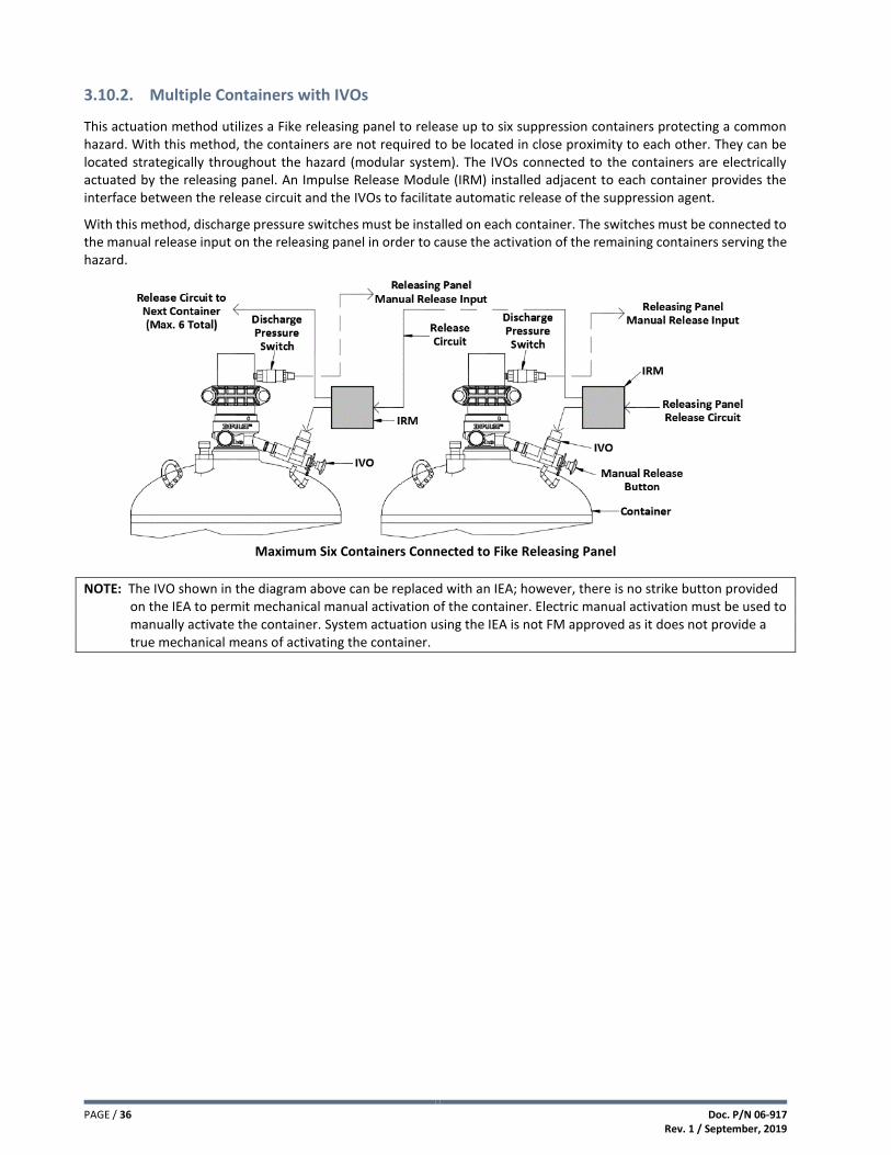
PAGE / 36 Doc. P/N 06-917 Rev. 1 / September, 2019
3.10.2. Multiple Containers with IVOs
This actuation method utilizes a Fike releasing panel to release up to six suppression containers protecting a common hazard. With this method, the containers are not required to be located in close proximity to each other. They can be located strategically throughout the hazard (modular system). The IVOs connected to the containers are electrically actuated by the releasing panel. An Impulse Release Module (IRM) installed adjacent to each container provides the interface between the release circuit and the IVOs to facilitate automatic release of the suppression agent.
With this method, discharge pressure switches must be installed on each container. The switches must be connected to the manual release input on the releasing panel in order to cause the activation of the remaining containers serving the hazard.
Maximum Six Containers Connected to Fike Releasing Panel
NOTE: The IVO shown in the diagram above can be replaced with an IEA; however, there is no strike button provided on the IEA to permit mechanical manual activation of the container. Electric manual activation must be used to manually activate the container. System actuation using the IEA is not FM approved as it does not provide a true mechanical means of activating the container.

Doc. P/N 06-917 Rev. 1 / September, 2019
PAGE / 37
3.10.3. Two Containers with IVO and IVPO
This actuation method utilizes a Fike releasing panel to release up to two suppression containers protecting a common hazard. With this method, the containers are required to be located in close proximity to each other to facilitate connection of the pilot line hoses. The IVO connected to the Primary container is electrically actuated by the releasing panel. An Impulse Release Module (IRM) installed adjacent to the Primary container provides the interface between the release circuit and the IVO to facilitate automatic release of the suppression agent. The Secondary container is equipped with an Impulse Valve Pneumatic Operator (IVPO) that allows the container to be pneumatically activated by the discharge pressure supplied by the primary container through the pilot line hoses.
With this method, manual activation of the suppression containers can be accomplished either electrically or mechanically. Electric manual activation is accomplished by the activation of a manual release switch connected to the releasing panel. Mechanical manual activation is accomplished by striking the red button on the IVO connected to the primary container. This method of activating the container does not require an electric power source. Where mechanical manual activation of the system is possible, NFPA 2001 requires that a discharge pressure switch must be installed to provide an indication to the releasing panel that the system has been manually activated. Connect the discharge pressure switch to a “Manual Release” input on the releasing panel.
Maximum Two Containers Connected to Fike Releasing Panel
Pilot Line Limitations: 1) Pilot line hoses supplied by Fike.
NOTE: The IVO shown in the diagram above can be replaced with an IEA; however, there is no strike button provided on the IEA to permit mechanical manual activation of the container as described above. Electric manual activation must be used to manually activate the container. System actuation using the IEA is not FM approved as it does not provide a true mechanical means of activating the container.
See Section 4.8 for pilot line installation.

PAGE / 38 Doc. P/N 06-917 Rev. 1 / September, 2019
3.10.4. Multiple Containers with Single IVO and Multiple IVPOs
This actuation method utilizes a Fike releasing panel to release up to seven suppression containers protecting a common hazard. With this method, the containers are required to be located in close proximity to each other to facilitate connection of the pilot line hoses. The IVO connected to the Primary container is electrically actuated by the releasing panel. An Impulse Release Module (IRM) installed adjacent to the Primary container provides the interface between the release circuit and the IVO to facilitate automatic release of the suppression agent. The Secondary containers (six maximum) are equipped with Impulse Valve Pneumatic Operators (IVPO) that allow the containers to be pneumatically activated by the discharge pressure supplied by the primary container through the pilot line.
With this method, manual activation of the suppression containers can be accomplished either electrically or mechanically. Electric manual activation is accomplished by the activation of a manual release switch connected to the releasing panel. Mechanical manual activation is accomplished by striking the red button on the IVO connected to the primary container. This method of activating the container does not require an electric power source. Where mechanical manual activation of the system is possible, NFPA 2001 requires that a discharge pressure switch must be installed to provide an indication to the releasing panel that the system has been manually activated. Connect the discharge pressure switch to a “Manual Release” input on the releasing panel.
Maximum Seven Containers Connected to Fike Releasing Panel
Pneumatic Actuation Line Limitations: 1) Maximum 50 ft. (15.2 m) total length including hoses. 2) Maximum six IVPOs activated by primary container. 3) Tubing (supplied by others) shall be 1/4 in. x 0.035 in. wall stainless steel. 4) Pilot line hoses supplied by Fike.
NOTE: The IVO shown in the diagram above can be replaced with an IEA; however, there is no strike button provided on the IEA to permit mechanical manual activation of the container as described above. Electric manual activation must be used to manually activate the container. System actuation using the IEA is not FM approved as it does not provide a true mechanical means of activating the container.
See Section 4.8 for pilot line installation.

Doc. P/N 06-917 Rev. 1 / September, 2019
PAGE / 39
3.10.5. Multiple Containers with Primary Nitrogen Actuator
This actuation method utilizes a Primary Nitrogen Actuator to release up to six suppression containers protecting a common hazard. With this method, the containers are not required to be located in close proximity to each other. They can be located strategically throughout the hazard (modular system) and are connected together via a pilot line for actuation. The UVO connected to the Primary Nitrogen Actuator is electrically actuated by the releasing panel. The secondary containers are equipped with Impulse Valve Pneumatic Operators (IVPO) that allow the containers to be pneumatically activated by the discharge pressure supplied by the primary nitrogen actuator through the pilot line.
With this method, manual activation of the suppression containers can be accomplished either electrically or mechanically. Electric manual activation is accomplished by the activation of a manual release switch connected to the releasing panel. Mechanical manual activation is accomplished by striking the red button on the UVO connected to the Nitrogen Actuator. This method of activating the container does not require an electric power source. Where mechanical manual activation of the system is possible, NFPA 2001 requires that a discharge pressure switch must be installed to provide an indication to the releasing panel that the system has been manually activated. Connect the discharge pressure switch to a “Manual Release” input on the releasing panel.
NOTE: This actuation method is commonly used for system actuation in hazardous locations; however, the discharge pressure switch cannot be installed in the hazardous location.
Maximum Six Containers Connected to Primary Nitrogen Actuator
Pneumatic Actuation Line Limitations: 1) Minimum 100 ft. (30.5 m) between Primary Nitrogen Actuator and first IVPO. 2) Maximum 300 ft. (91.5 m) between Primary Nitrogen Actuator and last IVPO. 3) Maximum 160 ft. (48.8 m) between first and last IVPO. 4) Maximum six IVPOs activated by primary nitrogen actuator. 5) Tubing (supplied by others) shall be 1/4 in. x 0.035 in. wall stainless steel. 6) Pilot line hoses supplied by Fike.
NOTE: The UVO shown in the diagram above that is connected to the Primary Nitrogen Actuator Assembly can be replaced with a Universal Energetic Actuator (UEA); however, there is no strike button provided on the UEA to permit mechanical manual activation of the containers as described above. Electric manual activation must be used to manually activate the container. Activation of the Primary Nitrogen Actuator using the UEA is not FM approved as it does not provide a true mechanical means of activating the system.
See Section 4.8 for pilot line installation.

PAGE / 40 Doc. P/N 06-917 Rev. 1 / September, 2019
3.10.6. Multiple Containers with Primary and Secondary Actuators
This actuation method utilizes a Primary Nitrogen Actuator and one or more Secondary Nitrogen Actuators to release up to six suppression containers protecting a common hazard. With this method, the containers are not required to be located in close proximity to each other. They can be located strategically throughout the hazard (modular system) and are connected together via a pilot line for actuation. The UVO connected to the Primary Nitrogen Actuator is electrically actuated by the releasing panel. The secondary containers are equipped with Impulse Valve Pneumatic Operators (IVPO) that allow the containers to be pneumatically activated by the discharge pressure supplied by the secondary nitrogen actuator through the pilot line.
With this method, manual activation of the suppression containers can be accomplished either electrically or mechanically. Electric manual activation is accomplished by the activation of a manual release switch connected to the releasing panel. Mechanical manual activation is accomplished by striking the red button on the IVO connected to the Primary Nitrogen Actuator Assembly. This method of activating the container does not require an electric power source. Where mechanical manual activation of the system is possible, NFPA 2001 requires that a discharge pressure switch must be installed to provide an indication to the releasing panel that the system has been manually activated. Connect the discharge pressure switch to a “Manual Release” input on the releasing panel.
NOTE: This actuation method is commonly used for system actuation in hazardous locations; however, the discharge pressure switch cannot be installed in the hazardous location
Maximum Six Containers Connected to Primary and Secondary Nitrogen Actuators
Pilot Line Limitations: 1) Maximum 150 ft. (45.0 m) between Primary Nitrogen Actuator and Secondary Nitrogen Actuator. 2) Minimum 100 ft. (30.5 m) between Secondary Nitrogen Actuator and first IVPO. 3) Maximum 300 ft. (91.5 m) between Secondary Nitrogen Actuator and last IVPO. 4) Maximum 160 ft. (48.8 m) between first and last IVPO. 5) Maximum six IVPOs activated by secondary nitrogen actuator. 6) Tubing (supplied by others) shall be 1/4 in. x 0.035 in. wall stainless steel. 7) Pilot line hoses supplied by Fike.

Doc. P/N 06-917 Rev. 1 / September, 2019
PAGE / 41
NOTE: The UVO shown in the diagram that is connected to the Primary Nitrogen Actuator Assembly can be replaced with a Universal Energetic Actuator (UEA); however, there is no strike button provided on the UEA to permit mechanical manual activation of the containers as described above. Electric manual activation must be used to manually activate the container. Activation of the Primary Nitrogen Actuator using the UEA is not FM approved as it does not provide a true mechanical means of activating the system.
See Section 4.8 for pilot line installation.
3.11. Select Container Size and Fill Range
The selection of containers is generally determined by the total amount of agent required versus the approved fill ranges for the various container sizes. Additional factors such as the System Design Concept, container storage location, and flow calculation limitations may impact container selection.
To estimate the number of containers required, divide the Final Design Quantity required for each protected hazard by the actual container capacity listed in the Container Size and Fill Range table below. The container size(s) selected must be equal to or greater than the weight of the total agent quantity required. Containers are filled to the nearest lb. (kg).
CONTAINER SIZE AND FILL RANGE
Size lb. (L)
Part Number
Minimum Fill Range
lbs. (kg)
Maximum Fill Range
lbs (kg)
Fill Increments
lbs. (kg)
Mounting
Position
Valve
Size in. (mm)
Approx. Tare
Weight lbs. (kg)
5 (2) 70-357 3 (1.0) 5 (2.0) 1 (0.5) Upright (Valve Up) 1 (25) 11 (5.0)
10 (4) 70-358 5 (2.5) 10 (4.5) 1 (0.5) Upright (Valve Up) 1 (25) 15 (6.8)
20 (8.5) 70-359 9 (4.0) 21 (9.5) 1 (0.5) Upright (Valve Up) 1 (25) 19 (8.6)
35 (15) 70-360 17 (8.0) 38 (17.0) 1 (0.5) Upright (Valve Up) 1 (25) 28 (12.7)
60 (27) 70-361 30 (13.5) 68 (30.5) 1 (0.5) Upright (Valve Up) 1 (25) 53 (24.0)
100 (44) 70-362 47 (21.5) 108 (49.0) 1 (0.5) Upright (Valve Up) 1 (25) 77 (34.9)
150 (68) 70-363 65 (32.5) 150 (68.0) 1 (0.5) Upright (Valve Up) 3 (80) 123 (55.8)
215 (87) 70-364 93 (42.5) 216 (98.0) 1 (0.5) Upright (Valve Up) 3 (80) 150 (68.0)
375 (153) 70-365 163 (74.0) 378 (171.5) 1 (0.5) Upright (Valve Up) 3 (80) 216 (98.0)
650 (267) 70-366 283 (128.5) 660 (299.0) 1 (0.5) Upright (Valve Up) 3 (80) 364 (165.1)
1000 (423) 70-367 449 (203.5) 1045 (474.0) 1 (0.5) Upright (Valve Up) 3 (80) 525 (238.1)
3.12. Consider Container Manifold Options
For systems that require more agent than a single container can provide, multiple containers can be connected together via a common manifold arrangement to provide the required agent quantity to the protected hazard. Main and reserve supplies of agent are also connected together in this manner.
Manifolds are assembled using a combination of grooved pipe and fittings, or threaded pipe and fittings that meet the pressure requirements of NFPA 2001. When containers are manifolded together, every container must be the same size and fill weight in accordance with NFPA 2001.
See Section 4.3.4 for manifold configuration options.

PAGE / 42 Doc. P/N 06-917 Rev. 1 / September, 2019
3.13. Selector Valve Option
To reduce the total amount of agent required for protection of multiple hazards of similar or like volumes, the designer may want to consider using a selector valve system. The selector valve system utilizes a common agent supply that is sized to protect the largest hazard volume the suppression system serves. A dedicated piping network is connected to each selector valve to direct the agent flow to each individual hazard area. When the system activates, the appropriate selector valve will open to allow the agent flow to the affected hazard.
Activation of individual selector valves is accomplished using the discharge pressure provided by a Nitrogen Actuator Assembly through a stainless steel pilot line connection. See diagrams below.
Selector Valve Activation using Primary Nitrogen Actuator Assembly
Selector Valve Activation using Primary and Secondary Nitrogen Actuator Assemblies
CAUTION: Selector valve systems can only be used to protect one hazard at a time and will not be effective if two or more
hazards are involved in a fire simultaneously.
CAUTION: When using selector valves to protect hazards with similar volumes, it is extremely important that the system
designer evaluate the final design concentration that will be reached in each hazard area served by the selector
valve system to determine the impact on exposure limitations. See Section 3.21.

Doc. P/N 06-917 Rev. 1 / September, 2019
PAGE / 43
3.14. Determine Container Locations
The location of the agent container(s) must be based on the following considerations:
1) Container(s) must be installed in area that is capable of maintaining an ambient temperature of 32-130°F (0-
54.4°C). At temperatures outside this range, the system may not supply the desired quantity of agent or may
accidentally discharge due to over-pressure. The flow calculation program predictions are based on a container
storage temperature range of 60-80°F (16-27°C).
2) The gross weight of the container must be considered when selecting the container location. The floor must be
able to support the total weight of the container(s) as they are moved into position. Excessive floor loading
may require relocating the container(s) to a more suitable location.
3) Container(s) should be located as close as possible to or within the hazard(s) that they protect in order to
reduce the length of the distribution piping. For large systems, it may be necessary to sub-divide the piping
network into small configurations with separate containers.
4) Container(s) should be located in a clean, dry, and relatively vibration free area. Avoid aisle ways and other
high traffic areas where physical damage or tampering is more likely.
5) Container(s) should not be located where they would be subject to physical damage, exposure to corrosive
chemicals, or harsh weather conditions. Container(s) should not be located where they could potentially be
splashed or submerged with any liquid.
6) Container(s) should be located where they can be easily accessed for maintenance and service.

PAGE / 44 Doc. P/N 06-917 Rev. 1 / September, 2019
3.15. Determine Nozzle Quantity and Placement
Nozzle quantity and placement within each hazard being protected will be determined by many factors, such as size and
configuration of the hazard area, height of the ceiling, flow rates through the nozzles, nozzle area coverage, etc. At a
minimum, at least one nozzle shall be provided for each hazard area.
All nozzles used for the fire suppression system using 3M™ Novec™ 1230 Fire Protection Fluid are required to discharge
the agent into the protected hazard within 6 to 10 seconds; therefore, the number of nozzles provided for any area
must be capable of delivering the flow rate required to meet this timing criteria.
Each size nozzle is capable of delivering a defined flow rate. To estimate the minimum number and size of nozzles
required for each area, divide the total quantity of agent required for the protected hazard by 10 seconds to determine
the hazards total flow rate; then, use the Nozzle Flow Rate table below to select the nozzle(s) size best suited to provide
the required flow rate. More than one nozzle may be required for each protected hazard.
If the flow rate approaches the top end of the allowable flow rate for a given size pipe, it may be in the designer’s best
interest to increase the pipe size.
NOZZLE FLOW RATES
Nominal Pipe Size In. NPT (mm)
Minimum Design Flow Rate (System Limitation)
lbs./sec (kg/sec)
Maximum Design Flow Rate (Estimate Only)
lbs./sec (kg/sec)
1/2 (15) 1.29 (0.59) 3.23 (1.46)
3/4 (20) 2.43 (1.10) 6.08 (2.75)
1 (25) 4.12 (1.87) 10.30 (4.68)
1 ¼ (32) 7.40 (3.36) 18.50 (8.40)
1 ½ (40) 10.25 (4.65) 25.63 (11.63)
2 (50) 13.00 (5.90) 33.00 (14.97)
NOTE: The values listed in the table are provided for estimation purposes only. The final system design MUST be
verified using Fike’s Flow Calculation Program.
NOTE: A maximum nozzle flow rate of 17 lbs/sec (7.7 kg/sec) is recommended for all areas with false ceilings or
delicate operations where a higher flow rate may dislodge objects or affect a process.

Doc. P/N 06-917 Rev. 1 / September, 2019
PAGE / 45
3.15.1. Evaluate Nozzle Area Coverage
When determining the required quantity of nozzles for each protected hazard, the designer must consider the area coverage limitations of each nozzle. Each nozzle type (180° or 360°) has been UL Listed and FM Approved for the maximum area coverage limitations listed below.
The maximum area coverage is expressed as a radius (“R”) of coverage along the discharge axis for both nozzle types.
Nozzle Size – 1/2 in. to 2 in. (15 mm to 50 mm)
Nozzle Type
Radius “R” Dimension
ft. (m)
Ceiling Height Range
ft. (m)
180° 44.91 (13.69) 1.32 to 16.00 (0.40 to 4.88)
360° 28.41 (8.66) 1.32 to 16.00 (0.40 to 4.88)
NOTE: Enclosure heights <1.32’ (0.4 m) shall be ½ of the nozzle area coverage.
Nozzle Area Coverage
Maximum Distance 180° Nozzle ft. (m)
360° Nozzle ft. (m)
Note
Below Ceiling 1.0 (0.3) 1.0 (0.3) Maximum distance above highest point of protection when stacking nozzles. Away from Sidewall 1.0 (0.3) ---
40.02 ft
(12.2 m)
40.35 ft
(12.3 m)
“R”
“R”
40.02 ft
(12.2 m)

PAGE / 46 Doc. P/N 06-917 Rev. 1 / September, 2019
Nozzle Placement Recommendations
Nozzles must be located at the top of the hazard area, aimed up or down. Nozzle located in a subfloor can also be aimed
upward or downward.
360° Nozzle(s) should be located on or near the centerline of
the protected area, discharging toward the perimeter of the
area being protected. Nozzle coverage patterns need to
overlap to adequately cover the area without any “blind spots”
due to nozzle locations.
180° Nozzle(s) should be located along the perimeter of the
protected area, discharging toward the opposite side. Nozzle
coverage patterns need to overlap to adequately cover the
area without any “blind spots” due to nozzle locations. The
nozzles can be located a maximum of 1 ft. (0.3 m) out from the
wall.
180° Nozzle(s) in a back-to-back application should be located
on or near the centerline of the protected area, discharging
toward the perimeter of the area being protected. Maximum
distance between nozzles is 1 ft. (0.3 m). Nozzle coverage
patterns need to overlap to adequately cover the area without
any “blind spots” due to nozzle locations.
NOTE: The use of 180° nozzles in a back-to-back configuration
is UL Listed but not FM Approved.
“R”
“R”
360° Nozzle Placement
“R”
“R”
180° Nozzle Placement
1.0’ (0.3m)
“R”
“R”
180° Nozzle Placement
(Back-to-Back)
(B
360° Nozzle Placement

Doc. P/N 06-917 Rev. 1 / September, 2019
PAGE / 47
3.15.2. Evaluate Nozzle Quantity Based on Enclosure Ceiling Height
When determining the required quantity of nozzles for each protected hazard, the designer must consider the ceiling
height limitations for the nozzles. Each nozzle type (180° or 360°) has been UL Listed and FM Approved for enclosures
with a ceiling height of 16.0 ft. (4.9 m). Ceiling heights greater than 16.0 ft. (4.9 m) to 20.66 ft. (6.3 m) require nozzles
to be placed at multiple levels (elevations) in segments no greater than 16.0 ft. (4.1 m) in elevation. See 3.15.3 for
maximum elevation differences between pipe runs.
Nozzle Levels for Enclosure Greater than 16.0 ft. (4.9 m)
3.15.3. Evaluate Elevation Differences between Pipe Runs
NOTE: These limitations only apply to system where multiple hazards are protected by a single piping network.
20'-8" max
(6.3 m max)
20'-8" max
(6.3 m max)
20'-8" max
(6.3 m max)
20'-8" max.
(6.2 m max.)
Ceiling
1.0' max
(0.3 m max)
16.0' max
(4.9 m max)
1.0' max
(0.3 m max)
16.0' max
(4.9 m max)
(4.9 m max.)
Example 1:
Systems with a single level of
nozzle(s) above container outlet
Example 2:
Systems with a multiple level of
nozzle(s) above container outlet
Example 3:
Systems with a
single level of
nozzle(s) below
container outlet
Example 4:
Systems with
levels of nozzle(s)
above and below
container outlet

PAGE / 48 Doc. P/N 06-917 Rev. 1 / September, 2019
3.15.4. Evaluate Nozzle Discharge Obstructions
When solid obstructions, such as walls, partitions, equipment racks, and tall equipment, interfere with the nozzle
discharge path they should be treated as separate areas. All nozzles should be located in a manner that will provide a
clear discharge path that reaches all of the outer extremes for the protected space.
Side View Side View
3.16. Determine Piping Layout
Using a plan view drawing of the protected areas, locate each nozzle(s) and container(s); then connect the nozzles
together with piping.
3.16.1. Evaluate Minimum Piping Distances
In order to stabilize the flow and maintain the accuracy of the tee splits the following pipe design rules must be adhered
to:
A minimum of 2.41 feet (0.73 m) must be maintained
between tees for pipe sizes 2-1/2 inch (65 mm) and
smaller. For pipe sizes 3 inch (80 mm) and larger, a
minimum of ten (10) pipe diameters must be maintained
between tees.
A minimum of ten (10) pipe diameters must be
maintained between an elbow and a tee or a tee and
an elbow.
The ten (10) pipe diameter rule does not apply when using back-to-back 180° nozzle configurations as long as:
1) Agent supplied and flow rate from both nozzles are the same.
2) Pipe size from tee to both nozzles is the same.
3) Pipe lengths from tee to each nozzle are within 10% of each other.
Nozzle Orifices
must be below
Obstruction.
Beam, Ductwork,
Cable Tray, etc.
1 ft. (0.3 m)
Maximum from
Ceiling to Nozzle
Files, Storage
Racks,
Computers,
etc.
Top of
Obstruction
must be below
bottom of
Nozzle.

Doc. P/N 06-917 Rev. 1 / September, 2019
PAGE / 49
3.16.2. Evaluate Tee Split Ratios
Engineered systems using 3M™ Novec™ 1230 Fire Protection Fluid have been tested to define the maximum degree of
imbalance that can be predicted at piping tee splits. This value is expressed in terms of a split ratio of one outlet branch
versus the other as illustrated below.
TEE CONFIGURATION – BULLHEAD
Definition: Where the two-outlet branches change direction from the incoming piping inlet.
TEE CONFIGURATION – SIDE-THRU
Definition: Where one outlet branch changes direction from the inlet and the other continues straight through in the same direction as the inlet.
Correct T-Split Ratios
Incorrect T-Split Ratios

PAGE / 50 Doc. P/N 06-917 Rev. 1 / September, 2019
3.16.3. Evaluate Tee Orientation
Tee orientation plays an important characteristic in maintaining the consistency of the flow split percentages at tees; therefore, a simple rule must be observed concerning the orientation of tees. Every outlet of every tee must be orientated in the horizontal plane.
Correct Tee Orientation
Incorrect Tee Orientation

Doc. P/N 06-917 Rev. 1 / September, 2019
PAGE / 51
3.17. Estimate Pipe Sizes
Fike’s Flow Calculation Program will estimate pipe sizes automatically; therefore, this step is optional. However, the
designer may wish to use the following pipe size estimation chart to estimate the nozzle pipe sizes for quotation
purposes.
Pipe size estimations are based on the design flow rate for each pipe section. To determine the flow rate of a pipe
section, divide the amount of agent flowing through the pipe section by the discharge time (10 seconds).
Pipe Size In. NPT (mm)
Pipe Schedule
Minimum Design Flow Rate lbs/sec (kg/sec)
(System Limitation)
Maximum Design Flow Rate lbs/sec (kg/sec)
(Estimate)
1/2 (15) 40 1.50 (0.68) 3.76 (1.71)
3/4 (20) 40 2.65 (1.21) 6.65 (3.02)
1 (25) 40 4.33 (1.96) 10.83 (4.91)
1 1/4 (32) 40 7.55 (3.42) 18.88 (8.56)
1 1/2 (40) 40 10.31 (4.68) 25.78 (11.69)
2 (50) 40 17.10 (7.76) 42.75 (19.39)
2 1/2 (65) 40 24.51 (11.12) 61.28 (27.80)
3 (80) 40 38.05 (17.26) 95.13 (43.15)
4 (100) 40 65.95 (29.91) 164.88 (74.79)
6 (150) 40 151.16 (68.57) 377.90 (171.41)
8 (200) 40 263.51 (119.53) 658.78 (298.82) Pipe Size estimations are based on Schedule 40 pipe.
Generally, the size selection should be based on the smallest pipe size that will handle the design flow rate for the
branch lines supplying the discharge nozzles and the next to smallest for trunk lines. If the flow rate approaches the top
end of the allowable flow rate for a given pipe size, it may be necessary to increase the pipe size.
WARNING: DO NOT install the piping system based on the pipe size estimates from the chart above. The pipe system
design must be verified using Fike’s Flow Calculation Program prior to installing the system.

PAGE / 52 Doc. P/N 06-917 Rev. 1 / September, 2019
3.18. Apply Tee Design Factor
When a single agent supply is being used to protect multiple hazards, a tee design factor is applied when more than four
tees are used. The tee design factor is meant to compensate for the uncertainty in the quantity of agent flowing through
a pipe as the agent passes through an increasing number of tees. The design factor tee count shall be determined for
each hazard the system protects, using the following guidelines:
1) Starting from the point where the piping enters the hazard that is located farthest (hydraulically) from the agent
container(s), count the number of tees in the direct flow path as it returns to the agent container(s). Do not
include tees that are used in the manifold (if applicable). If you are not sure which hazard is farther away, count
the tees in the flow path from each hazard and use the highest number.
2) Any tee within the hazard that supplies agent to another hazard shall be included in the tee count for the hazard.
3) After determining the tee count, use the chart below to determine the Tee Design Factor.
4) Apply the Tee Design Factor to the Agent Quantity calculations by multiplying the Tee Design Factor by the
amount of agent previously determined in the volumetric calculations.
Design Factors for Piping Tees
Tee Count Design Factor Tee Count Design Factor
0 - 4 0.00 12 0.07
5 0.01 13 0.08
6 0.02 14 0.09
7 0.03 15 0.09
8 0.04 16 0.10
9 0.05 17 0.11
10 0.06 18 0.11
11 0.07 19 0.12
EXAMPLE:
This example shows a multi-hazard area arrangement. Starting at the point where the piping enters the hazard farthest away, count the number of tees leading back to the agent container. With a tee count of five (5), an additional 1% (0.01) of agent is required. Therefore, the base quantity of agent is multiplied by 1.01 (1%) to determine the adjusted quantity of agent required
NOTE: Fike recommends increasing the design concentration to 4.7% for Class A or Class C when protecting multiple hazards with single agent supply. This will satisfy the tee design factor requirement.
#2
#5
Hazard
#4
Hazard
#3
Hazard
#2
Hazard
#1
Start Here
#1
#3
#4

Doc. P/N 06-917 Rev. 1 / September, 2019
PAGE / 53
3.19. Determine the Final Design Quantity Required
Add the agent quantities required for all areas together to determine the Final Design Quantity required for the entire system adjusted to account for design factors and pressure adjustments.
3.20. Determine Design Concentration at Maximum Temperature
This step is necessary to properly evaluate the exposure and egress time limitations discussed in Section 3.21 in order
to avoid over-concentrating the area due to the additional agent being supplied to the area and the increased volume
of agent caused by increased temperature. To determine the expected agent concentration at Maximum Ambient
Temperature, the following formula must be used:
100WS C = ---------- V + WS
Where: W = Agent Weight in lbs. (kg)
V = Hazard Volume / ft3 (m3)
C = Design Concentration, % by volume
S = Specific Vapor in ft3/lb (m3/kg)
See Flooding Factor Table on page 31 to determine the “S” value
NOTE: It is important to verify that the worst case design concentration will not exceed the limits for fire suppression
on the low end and life safety on the high end.
NOTE: Fike’s Flow Calculation Program will automatically calculate the design concentration at the maximum ambient temperature entered.
3.21. Evaluate Exposure Limitations
Unnecessary exposure to 3M™ Novec™ 1230 Fire Protection Fluid at and above the no observable adverse effects
level (NOAEL) and decomposition products produced by the fire shall be avoided. The following provisions shall apply:
1. When Novec 1230 fluid is used in a “Normally Occupied” area, a maximum design concentration of 10% is
allowed. Concentrations greater than 10% can only be used in “Unoccupied” areas.
2. When Novec 1230 fluid is used in a “Normally Occupied” area and is designed to concentrations up to the
NOAEL, the maximum exposure time shall not exceed 5 minutes.
3. When Novec 1230 fluid is used in a “Not Normally Occupied” area and is designed to concentrations above the
LOAEL, the following provisions shall apply:
A. Where egress takes long than 30 seconds but less than 1 minute, the agent concentration shall not exceed
its LOAEL.
B. Concentrations exceeding the LOAEL shall be permitted provided that any personnel in the area can escape
within 30 seconds.
C. A pre-discharge alarm and time delay shall be provided.

PAGE / 54 Doc. P/N 06-917 Rev. 1 / September, 2019
3.22.
With the information developed in previous sections, run Fike’s Flow Calculation Program to determine the final pipe sizes and nozzle orifices. Refer to Appendix A. The program will flag most errors and prevent a completed flow calculation until all errors have been corrected. The following are common errors generated by the flow calculation program.
3.22.1. Percent Agent in Pipe
Fike containers filled with 3M™ Novec™ 1230 Fire Protection Fluid are pressurized with nitrogen to expel the extinguishing agent through the piping network and into the protected space; therefore, the total agent weight (liquid) that may reside in the piping network during discharge is limited to 88% maximum. This is to ensure that enough pressure is available in the pipe network to deliver the agent to the protected space within the maximum discharge time of 10 seconds.
This error indicates that the piping network is too large and that the piping network must be decreased by reducing pipe sizes, reducing pipe lengths, or a combination of both to correct this error. The flow calculation program will indicate the following error message “Percent of Agent Greater Than 88%”.
3.22.2. Location of First Tee
Some piping configurations can present timing problems for the flow calculation program due to the degree of hydraulic imbalance created due to the location of the first tee. For example, a system that splits and supplies agent for the room nozzles and underfloor nozzles is unbalanced because of the difference in pipe size and agent quantities. Therefore, the flow calculation program must try to manipulate the nozzle orifice hole diameters in an attempt to satisfy all of the timing requirements for the system. When the timing criteria cannot be met, the location of the first tee becomes critical.
To eliminate this problem, a minimum distance of 18 inches (457 mm) or 15 pipe diameters, whichever is larger, must be maintained from the container to the first tee in the piping network.
3.22.3. Liquid Arrival Time
The time necessary for liquid agent to arrive at each nozzle must be within 1.15 second of each other, as shown in the example below.
In the example above, if liquid agent takes 2 seconds to arrive at the first nozzle (the closest nozzle to the container) after system discharge, liquid agent must arrive at the remaining nozzles within 1.15 second (3.15 seconds maximum after system discharge).
2.0 seconds
2.5 seconds
3.15 seconds

Doc. P/N 06-917 Rev. 1 / September, 2019
PAGE / 55
3.22.4. Liquid Runout Time
The time necessary for liquid agent to discharge (runout) at each nozzle must be within 1.5 seconds of each other, as shown in the example below.
In the example above, if liquid runout time for the first nozzle (the closest nozzle to the container) takes 7 seconds after system discharge, the liquid runout time for the remaining nozzles must not exceed 8.5 seconds.
3.22.5. Nozzle Orifice Area Limitations (180° and 360°)
3.23. Verify System Performance
Once the flow calculation has been completed, it is important that the designer review all results to verify system performance. The designer must review the “System Acceptance” report generated by the flow calculation program to verify that the minimum design concentrations have been achieved in all hazard enclosures.
Refer to Appendix A for Engineered System design example.
3.24. Evaluate Selector Valve Pipe Design
On a selector valve system, only one selector valve will activate at a time to direct the agent to flow to the protected
hazard it serves. The remaining valves will remain closed. This creates a situation where a considerable quantity of agent
can become entrapped in the discharge piping leading up to the closed selector valves.
To account for this loss of agent flow, the layout of the piping network supplying the selector valves must be evaluated
to verify that the piping network will not allow more than 10% of the supplied agent quantity to become trapped in the
piping, regardless of which selector valve activates.
Use the following steps to perform the evaluation.
Step 1. Perform flow calculations for each hazard to determine the required pipe sizes and schedule for the pipe
network.
Step 2. Using the determined pipe size and schedule from the flow calculations, refer to the table on the following
page to determine the multiplier that must be used to calculate the maximum allowable length of pipe in feet
for each pipe size and schedule.
Minimum Orifice Area Maximum Orifice Area Minimum Pressure
15% – Pipe cross sectional area 75% – Pipe cross sectional area 82 psia / 67.3 psig (5.65 bar absolute)
7.0 seconds
7.9 seconds
8.5 seconds

PAGE / 56 Doc. P/N 06-917 Rev. 1 / September, 2019
Step 3. Multiply the total agent quantity required by the hazard by the
chosen multiplier to determine the maximum length of pipe
allowed so as not exceed the 10% limitation.
Step 4. Evaluate the piping network to determine which selector valve (if
activated) would cause the greatest amount of agent to become
entrapped in the pipe network. This is done by totaling the length
of each pipe section where the agent will be entrapped with no
flow. If in doubt as to which selector valve presents the worst case
scenario, evaluate each selector valve individually.
Step 5. Compare the allowable pipe length determined in Step 3 against
the designed pipe network that serves the selector valves. As long
as the quantity of pipe that allows the entrapment of agent does
not exceed the value calculated in Step 3, the piping network is
acceptable. If exceeded, the piping network must be modified.
Refer to Appendix C for example.
3.25. Equivalent Length Values
The following table lists the equivalent length values used by Fike’s Flow Calculation Program for various pipe fittings. Values are based on Schedule 40 pipe.
Pipe Size In. NPT (mm)
Union ft. (m)
45° Elbow ft. (m)
90° Elbow ft. (m)
Thru Tee ft. (m)
Side Tee ft. (m)
Check Valve ft. (m)
1/2 (15) 0.4 (0.12) 0.8 (0.24) 1.7 (0.52) 1.0 (0.30) 3.4 (1.04) - - -
3/4 (20) 0.5 (0.15) 1.0 (0.30) 2.2 (0.67) 1.4 (0.43) 4.5 (1.37) - - -
1 (25) 0.6 (0.18) 1.3 (0.40) 2.8 (0.85) 1.8 (0.55) 5.7 (1.74) 2.0 (0.61)
1-1/4 (32) 0.8 (0.24) 1.7 (0.52) 3.7 (1.13) 2.3 (0.70) 7.5 (2.29) - - -
1-1/2 (40) 0.9 (0.27) 2.0 (0.61) 4.3 (1.31) 2.7 (0.82) 8.7 (2.65) - - -
2 (50) 1.2 (0.37) 2.6 (0.79) 5.5 (1.68) 3.5 (1.07) 11.2 (3.41) 4.0 (1.22)
2-1/2 (65) 1.4 (0.43) 3.1 (0.94) 6.6 (2.01) 4.1 (1.25) 13.4 (4.08) - - -
3 (80) 1.8 (0.55) 3.8 (1.16) 8.2 (2.50) 5.1 (1.55) 16.6 (5.06) 4.0 (1.22)
4 (100) 2.4 (0.73) 5.0 (1.52) 10.7 (3.26) 6.7 (2.04) 21.8 (6.64) - - -
6 (150) 3.5 (1.07) 7.6 (2.32) 16.2 (4.94) 10.1 (3.08) 32.8 (10.00) - - -
The following table lists equivalent length values for the container Impulse valves.
Impulse Valve Size 1 in. (25 mm) 3 in. (80 mm)
Equivalent Length 6.03 ft. (1.84 m) 30.90 ft. (9.42 m)
Selector Valve Multipliers
Pipe Size
In.
Pipe Schedule
Multiplier
1/2 40 0.474621
80 0.615945
3/4 40 0.270441
80 0.333518
1 40 0.166869
80 0.200495
1 1/4 40 0.096420
80 0.112426
1 1/2 40 0.070840
80 0.081610
2 40 0.042978
80 0.048840
2 1/2 40 0.030122
80 0.034027
3 40 0.019508
80 0.021834

Doc. P/N 06-917 Rev. 1 / September, 2019
PAGE / 57
4. INSTALLATION
The system installation shall be performed by an Authorized Fike Distributor in accordance with the requirements of
this manual and all appropriate codes and standards adopted by the AHJ.
Specific installation drawings must be prepared for the hazard area in accordance with the system design as calculated
by Fike’s Flow Calculation Program. System installation shall closely follow the drawings to ensure the system meets its
design criteria. The piping network is designed to obtain correct discharge time, nozzle pressures, agent quantity and
various other design considerations. If for any reason, the pipe network requires modifications, the system must be
recalculated before proceeding with installation.
4.1. Agent Storage Container Floor Loading
Floor loading must be considered when installing the agent storage containers. The floor must be able to support the
total weight of the Fike container(s) as they are moved into position and set in their final mounting place. Where the
container is to be mounted onto a raised floor, it is extremely important that the raised floor manufacturer be consulted
for floor loading limitations. Fike cannot assume responsibility for determining the suitability of a particular raised floor
system to support the suppression container(s); however, the following guidelines provide information to help
determine installation requirements:
When clean agent containers are located on a raised floor, floor integrity must be considered to determine if
the type of tile and vertical floor support can handle the increased load. If necessary, additional floor supports
can be added.
To help distribute the container weight over a greater area, a 1/4 inch thick steel plate sized to span multiple
floor supports can be placed under the container(s). If the container spans multiple floor tiles, add additional
floor supports in the area where the container(s) are installed. Minimum of four floor supports, one at each
corner of floor tile, must be used. Excessive floor loading may require relocating the container(s) to a more
suitable location. See the floor loading information table below for container floor loading information.
Floor Loading/Area By Container Size
Container Size
Total Container Weight (Note 1)
Container Floor Area
Container Floor Loading
Container Floor Area w/ Plate
(Note 2)
Container Floor Loading w/ Plate
(Note 3)
lb. (L) lbs. kg ft2 m2 lbs/ft2 kg/m2 ft2 m2 lbs/ft2 kg/m3
1000 (423) 1570 712 3.14 0.29 500 2440 4.0 0.36 398 2007
650 (267) 1024 464 3.14 0.29 326 1591 4.0 0.36 262 1319
375 (153) 594 269 2.18 0.20 272 1329 4.0 0.36 154 777
215 (88) 366 166 2.18 0.20 168 819 4.0 0.36 97 490
150 (61) 273 124 2.18 0.20 125 611 4.0 0.36 74 372
100 (44) 185 84 0.63 0.06 294 1433 4.0 0.36 52 261
60 (27) 121 55 0.63 0.06 192 937 4.0 0.36 36 181
35 (15) 66 30 0.27 0.02 247 1206 4.0 0.36 22 112
20 (8.5) 40 18 0.27 0.02 150 731 4.0 0.36 16 79
10 (4) 25 11 0.09 0.009 266 1299 4.0 0.36 12 60
5 (2) 16 7 0.09 0.009 170 832 4.0 0.36 10 49 NOTES:
1) Total container weight is based on container tare weight + maximum fill weight. 2) Plate size = 1/4 in. x 2 ft. x 2 ft. plate (6.4 mm x 0.6 mm x 0.6 mm). 3) Total container weight + 22.5 lbs. (10.2 kg) for plate used to calculate container w/ plate floor loading.

PAGE / 58 Doc. P/N 06-917 Rev. 1 / September, 2019
4.2. Installing Agent Storage Containers
Fike containers are supplied with a mounting bracket that must be securely mounted to a solid, load-bearing surface
that will support the container load. Anchoring into plaster, sheetrock wall or any other facing material is NOT
acceptable. As an option, some brackets may be welded into place. Some installations may require additional mounting
support not supplied by Fike.
Before mounting the container, check the container label to verify the container part number against the system
installation drawings to make sure that the correct container is being installed.
4.2.1. Mounting Detail for 5, 10, 20 and 35 lb. (2, 4, 8.5 and 15 L) Containers
Step 1. Secure the container mounting bracket to the wall or floor using suitable hardware (not supplied).
WARNING: Containers shall NOT be mounted horizontally. Mounting in the horizontal position will result in an
incomplete discharge.
Step 2. Install the container into the mounting bracket making sure that the container foot-ring is resting on the
bracket seat.
Step 3. Position the container within the mounting bracket so the pressure gauge and actuator port are easily visible
and accessible.
Step 4. Insert the top and bottom container U-bolts through the holes provided in the mounting bracket and secure
with the washers and nuts provided.
DIMENSION
CONTAINER SIZE
5 lb. (2 L) in. (mm)
10 lb. (4 L) in. (mm)
20 lb. (8.5 L) in. (mm)
35 lb. (15 L) in. (mm)
A 12.3 (312) 12.3 (312) 16.3 (414) 16.3 (414)
B 4.0 (102) 4.0 (102) 6.9 (175) 6.9 (175)
C 5.7 (145) 5.7 (145) 7.5 (191) 7.5 (191)
D 1.4 (35) 1.4 (35) 2.0 (51) 2.0 (51)
E 4.0 (102) 4.0 (102) 6.5 (165) 6.5 (165)
F 1.0 (25) 1.0 (25) 1.0 (25) 1.0 (25)
G 2.5 (64) 2.5 (64) 3.0 (75) 3.0 (75)
H 8.0 (203) 8.0 (203) 9.7 (246) 9.7 (246)
I 1.8 (45) 1.8 (45) 3.6 (91) 3.6 (91)
J 5.0 (127) 5.0 (127) 7.5 (191) 7.5 (191)
K 3.0 (76) 3.0 (76) 5.0 (127) 5.0 (127)
L N/A N/A 2.3 (58) 2.3 (58)
All dimensions are approximate.

Doc. P/N 06-917 Rev. 1 / September, 2019
PAGE / 59
4.2.2. Mounting Detail for 60 lb. (27 L) Container
Step 1. Secure the container mounting bracket (supplied with container) to the wall or floor using suitable hardware
(not supplied).
WARNING: Containers shall NOT be mounted horizontally. Mounting in the horizontal position will result in an
incomplete discharge.
Step 2. Install the container into the mounting bracket making sure that the container foot-ring is resting on the
bracket seat.
Step 3. Position the container within the mounting bracket so the pressure gauge and actuator port are easily visible
and accessible.
Step 4. Insert the top and bottom container U-bolts through the holes provided in the mounting bracket and secure
with the washers and nuts provided.

PAGE / 60 Doc. P/N 06-917 Rev. 1 / September, 2019
DIMENSION in. (mm)
A 20.00 (508.0)
B 1.75 (44.6)
C 13.19 (335.0)
D 4.25 (107.9)
E 11.16 (283.4)
F 1.15 (29.3)
G 0.75 (19.1)
H 18.50 (469.9)
I 0.75 (19.1)
J 12.19 (309.8)
K 9.00 (228.6)
L 3.50 (88.9)
M 4.88 (123.8)
N 13.63 (346.1)
O 1.50 (38.1)
All dimensions are approximate.

Doc. P/N 06-917 Rev. 1 / September, 2019
PAGE / 61
4.2.3. Mounting Detail for 150 lb. (61 L) Container
Step 1. Secure the container mounting bracket (supplied with container) to the container with the washer and nuts
provided.
WARNING: Containers shall NOT be mounted horizontally. Mounting in the horizontal position will result in an
incomplete discharge.
Step 2. Move the container to its correct mounting location.
Step 3. Position the container so the pressure gauge and actuator port are easily visible and accessible.
Step 4. Secure the mounting bracket to the wall using suitable hardware (not supplied).
DIMENSION in. (mm)
A 13.19 (335.3)
B 6.41 (162.4)
C 1.81 (46.1)
D 9.19 (233.7)
E 11.19 (284.2)
F 1.00 (25.6)
G 2.00 (50.8)
H 5.22 (132.8)
I 0.75 (19.1)
J 18.18 (461.8)
K 20.81 (528.6)
All dimensions are approximate.
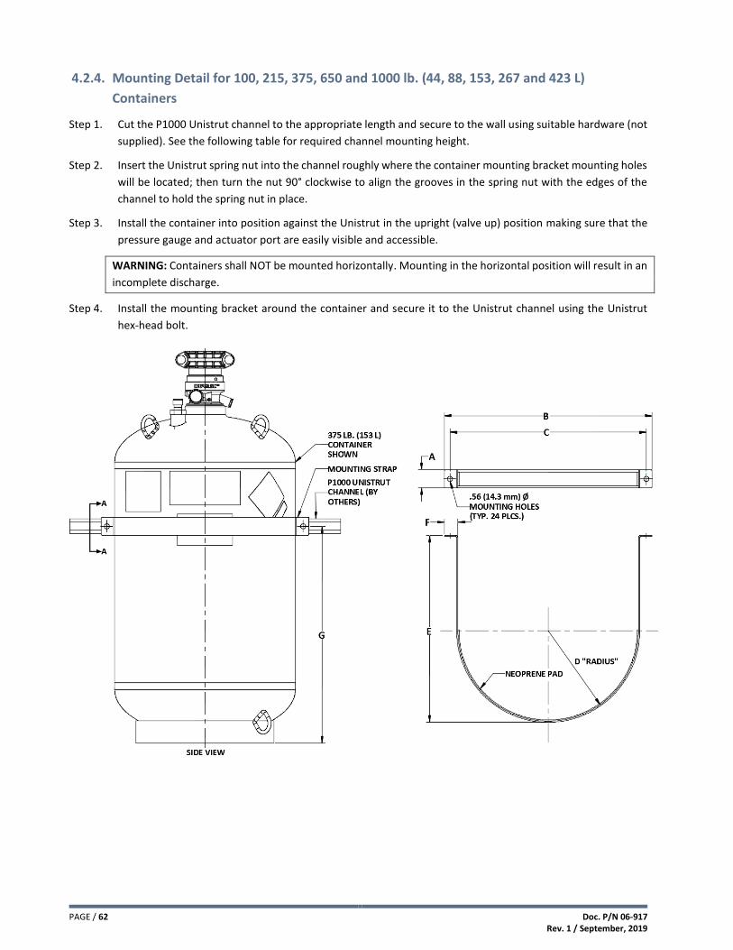
PAGE / 62 Doc. P/N 06-917 Rev. 1 / September, 2019
4.2.4. Mounting Detail for 100, 215, 375, 650 and 1000 lb. (44, 88, 153, 267 and 423 L)
Containers
Step 1. Cut the P1000 Unistrut channel to the appropriate length and secure to the wall using suitable hardware (not
supplied). See the following table for required channel mounting height.
Step 2. Insert the Unistrut spring nut into the channel roughly where the container mounting bracket mounting holes
will be located; then turn the nut 90° clockwise to align the grooves in the spring nut with the edges of the
channel to hold the spring nut in place.
Step 3. Install the container into position against the Unistrut in the upright (valve up) position making sure that the
pressure gauge and actuator port are easily visible and accessible.
WARNING: Containers shall NOT be mounted horizontally. Mounting in the horizontal position will result in an
incomplete discharge.
Step 4. Install the mounting bracket around the container and secure it to the Unistrut channel using the Unistrut
hex-head bolt.

Doc. P/N 06-917 Rev. 1 / September, 2019
PAGE / 63
“A-A” Unistrut Mounting Detail
DIMENSION CONTAINER SIZE
100 lb. (44 L) in. (mm)
215 lb. (88 L) in. (mm)
375 lb. (153 L) in. (mm)
650 lb. (267 L) in. (mm)
1000 lb. (423 L) in. (mm)
A 1.50 (38.1) 2.00 (51.0) 2.00 (51.0) 2.00 (51.0) 2.00 (51.0)
B 13.26 (336.8) 23.00 (584.2) 23.00 (584.2) 27.38 (696.5) 27.38 (696.5)
C 12.25 (311.2) 21.74 (522.2) 21.74 (522.2) 26.12 (663.5) 26.12 (663.5)
D 5.50 (139.7) 10.00 (254.0) 10.00 (254.0) 12.19 (309.6) 12.19 (309.6)
E 11.00 (279.8) 20.42 (518.7) 20.42 (518.7) 24.00 (610.0) 24.00 (610.0)
F 1.13 (28.7) 1.50 (38.1) 1.50 (38.1) 1.50 (38.1) 1.50 (38.1)
G 20.00 (508.0) 11.00 (279.0) 24.00 (609.6) 28.00 (711.0) 40.00 (1016.0)
All dimensions are approximate.

PAGE / 64 Doc. P/N 06-917 Rev. 1 / September, 2019
4.3. Installing Distribution Piping
In general, distribution piping should be installed in strict accordance to the requirements of NFPA 2001, requirements
of the local AHJ and in accordance with the design drawings and calculations prepared for the project. If piping
changes are necessary, the system must be recalculated using Fike’s Flow Calculation Program.
NOTE: For additional information on pressure rating of pipe and fittings, plus recommended pipe supports and hangers,
refer to FSSA’s Pipe Design Handbook, FSSA PDH-01.
4.3.1. Pipe and Fittings Materials
Piping materials must conform to the requirements as outlined in NFPA 2001, latest edition. The thickness of the piping
wall shall be calculated in accordance with ASME B31.1 Power Piping Code. For Fike Clean Agent Systems, with an agent
container charging pressure of 500 psig (34.5 bar) at 70°F (21°C), use a minimum piping design pressure of 460 psig (31.7
bar). Black or galvanized steel pipe shall conform to ASTM A-53, Type E, F, or S, Grade A or B, or ASTM A-106, Type S,
Grade A, B, or C. 1/2" to 6" Schedule 40 and Schedule 80 Threaded, Welded, and Cut Grooved or Rolled Grooved
configurations are acceptable.
CAUTION: Cast iron pipe, steel pipe conforming to ASTM A120, or nonmetallic pipe shall not be used.
Fitting materials must conform to the requirements outlined in NFPA 2001. Fitting sizes up to and including six inch NPT
shall be Class 300 malleable or ductile iron. Fittings over six inch NPT shall be Class 300 flanged fitting.
All grooved fittings must be UL Listed and conform to the pressure requirements outlined in NFPA 2001, latest edition.
Cast iron or Class 150 fittings shall not be used.
4.3.2. Pipe Size Changes
Pipe size changes, to increase or decrease the size, can be done at three different locations in the piping network:
Pipe Size Change at a Tee - When the change in pipe size is done at a tee, it is accomplished by using either a reducing tee or a standard tee and reducing fittings. All reducers must be concentric bell reducers or concentric reducing couplings.
Pipe Size Change at an Elbow - When the change in pipe size is done at an elbow, it is accomplished by using reducing elbows, a standard elbow with concentric bell reducers, or concentric reducing couplings.
Pipe Size Change at a Coupling - When the change in pipe size is done at a coupling, only concentric bell reducers or concentric reducing couplings can be used.
CAUTION: Reducing bushings, weld-o-let, and hole-cut fittings shall not be used.
4.3.3. General Piping Requirements
All pipe lengths are measured center-to-center of fittings.
Before installation, the pipe and fittings shall be carefully reamed, blown clear of chips and scale, and cleaned
internally with a nonflammable cleaner such as Perchlorethylene in accordance with NFPA 2001, latest edition.
The inside of the pipe and fittings must be free of oil and dirt.
PTFE tape, thread sealant or compound shall be used on male threads only. If using tape, do NOT allow it to
overlap the pipe opening as this could cause possible blockage of the agent
All grooved coupling gaskets shall be lubricated per the manufacturer's specifications.
A dirt trap consisting of a tee with a capped nipple, at least 2 inches (50 mm) long, shall be installed at the end of each pipe run.

Doc. P/N 06-917 Rev. 1 / September, 2019
PAGE / 65
4.3.4. Manifolds
Manifolds are supplied by others and are commonly assembled using grooved fittings; however, threaded, welded or
flanged fittings can also be used. They allow multiple containers to be connected to a common pipe network. They may
also be used in a system where Main/Reserve container arrangements are required.
The number of containers that can be connected to a single manifold is determined (calculated) by Fike’s Flow
Calculation Program. Every container connected to the same manifold must be the same type, size, and identical fill
weight. Check valves are required for each container being connected to the manifold.
Manifolds should not be supported by the containers. The manifold should be secured with pipe hangers or brackets to
support the “dead load” of the manifold should the container(s) be removed for service.
NOTE: The General Piping Requirements outlined in Section 4.3.3 must be adhered to when constructing manifolds.
TYPICAL MANIFOLD CONFIGURATION OPTIONS
Center Exit Manifold or Main/Reserve System
Center Exit Manifold or
Main/Reserve System with Multiple Containers
End Exit Manifold or
Main/Reserve System
End Exit Manifold or
Main/Reserve System with Multiple Containers

PAGE / 66 Doc. P/N 06-917 Rev. 1 / September, 2019
4.3.5. Pipe Hangers and Supports
The following general guidelines provide information for the selection and application of pipe hangers and supports
utilized to support the pipe network in all conditions of operation, including shock loads or thrusts created during
system operation. These guidelines are not intended to provide all information necessary to determine equipment
and material requirements for specific installation or applications.
NOTE: Refer to FSSA Pipe Design Guide (PDH-01) for addition guidance on pipe hangers and supports.
General Guidelines:
Pipe hangers and supports shall be installed in accordance with recognized industry practices and
manufacturer’s instructions.
All pipe hangers and supports shall be attached directly to a rigid fixed structure.
All hangers and components shall be steel.
Ordinary cast-iron hangers/supports, conduit clamps, or “C” clamps shall not be used.
Rigid hangers shall be installed wherever a change in elevation or direction occurs.
Nozzles shall be supported so as to prevent movement of the nozzle of the nozzle during discharge.
Where seismic bracing is required, bracing shall be in accordance with local codes and the AHJ.
All pipe supports shall be designed and installed to prevent lateral movement of supported pipe during
system discharge while permitting longitudinal movement to accommodate expansion and contraction
caused by temperature changes.
Pipe hangers must be spaced according to the size of pipe as indicated in the following table.
Pipe Size in. (mm)
Maximum Distance Between Supports
ft. (m)
Rod Diameter in. (mm)
1/2 (15) 7 (2.1) 3/8 (9.5)
3/4 (20) 7 (2.1) 3/8 (9.5)
1 (25) 7 (2.1) 3/8 (9.5)
1 1/4 (32) 7 (2.1) 3/8 (9.5)
1 1/2 (40) 9 (2.7) 3/8 (9.5)
2 (50) 10 (3.0) 3/8 (9.5)
2 1/2 (65) 11 (3.4) 1/2 (12.7)
3 (80) 12 (3.7) 1/2 (12.7)
4 (100) 14 (4.3) 5/8 (15.9)
6 (150) 17 (5.2) 3/4 (19.0)
Hangers must be placed within 12 in. (300 mm) of each discharge nozzle and between elbows that are more
than 24 in. (600 mm) apart.

Doc. P/N 06-917 Rev. 1 / September, 2019
PAGE / 67
4.3.6. Selector Valves
Selector Valves are activated pneumatically using the pressure provided by a nitrogen actuator assembly. Two methods for activating the selector valve and the components required are shown below.
4.3.6.1. Selector Valve Activated by Primary Nitrogen Actuator Assembly
Step 1. Install item 1 in the piping network. Fike recommends that threaded unions or grooved couplings be installed
on each side of the valve to facilitate easy removal of the valve. Supports shall be installed on each side of the
selector valve to support its dead load. The pipe network shall NOT be used to support the selector valve.
Step 2. Install item 2 in close proximity to the selector valve to allow connection of item 3J. See Section 4.7.5 for
installation instructions.
Step 3. Apply PTFE tape to the NPT male threads of items 3C, 3D, 3E and 3H. Do NOT allow tape to overlap the end of
the fitting as this could cause possible blockage of the pressure port.
Step 4. Assemble items 3C, 3D and 3H together. Secure wrench tight.
Step 5. Remove plug from item 3A. Retain for future use.
Step 6. Screw the items assembled in Step 4 into the threaded port on item 3A. Secure wrench tight. Orient the
assembly so the side outlet of item 3D is positioned horizontally.
Step 7. Screw item 3E into the side outlet of item 3D. Secure wrench tight.
Step 8. Install item 3F onto item 3E.
Step 9. Screw item 3G onto item 3E. Secure wrench tight.
Step 10. Connect one end of item 3J to item 3H. Secure wrench tight.
Step 11. Connect the other end of item 3J to the JIC fitting on the selector valve. Secure wrench tight.
Step 12. Check to ensure that item 3A is armed (firing pin retracted).
CAUTION: Do NOT install the actuator to the nitrogen actuator with the firing pin extended as this may cause
accidental discharge.
Step 13. Connect item 3A wire leads to the host control panel or module. See 4.7.6.1.
Step 14. Connect item 3B wire leads to the host control panel or module. See 4.7.9.1.
Step 15. Remove the retaining clip and valve plug from item 2. Keep these items for future use should the container
have to be removed for service.
Step 16. Connect item 3A to item 2 and secure in place with item 3B. See 4.7.9.
CAUTION: Installation of the system actuation components should be the last item completed before the system is
placed into service.
The selector valve is now armed.

PAGE / 68 Doc. P/N 06-917 Rev. 1 / September, 2019
Selector Valve Activation by Primary Nitrogen Actuator Assembly
Item No.
Part Number Description Notes
1 02-15708-XX Carbon Steel Selector Valve1
Part of 70-396 Selector Valve Assembly
02-15709-XX Stainless Steel Selector Valve1
2 70-325-X Nitrogen Actuator Assembly
3A 02-13571 Universal Valve Operator (UVO)
IG71-247 Universal Energetic Actuator (UEA)
3B 02-14627 Universal Valve Operator Supervisor (UVOS)
3C 02-13640 1/8 in. NPT x 1/4 in. NPT Adapter
3D C02-1335 1/4 in. NPT Street Tee
3E 02-11766 1/4 in. NPT x G1/4 Adapter
3F 02-10926 1/4 in. Sealing Washer
3G IG71-026 Vent Valve Assembly
3H 02-4530 1/4 in. NPT x 1/4 in. JIC Adapter
3J 02-4977 1/4 in. JIC x 1/4 in. JIC Hose, 35 in. (889 mm) Long 1Valve material supplied is based on selector valve assembly part number.

Doc. P/N 06-917 Rev. 1 / September, 2019
PAGE / 69
4.3.6.2. Selector Valve Activated by Secondary Nitrogen Actuator Assembly
Step 1. Install item 1 in the piping network. Fike recommends that threaded unions or grooved couplings be installed
on each side of the valve to facilitate easy removal of the valve. Supports shall be installed on each side of the
selector valve to support its dead load. The pipe network shall NOT be used to support the selector valve.
Step 2. Install item 2 (secondary nitrogen actuator) in close proximity to the selector valve to allow connection of item
3C. See Section 4.7.5 for installation instructions.
Step 3. Apply PTFE tape to the NPT male threads of items 3B, 3E, 4C, 4D, 4E and 4G. Do NOT allow tape to overlap the
end of the fitting as this could cause possible blockage of the pressure port.
Step 4. Assemble items 3D, 3E, 3F, 3G and 3H together. Wrench tight.
Step 5. Connect items assembled in Step 4 to the JIC connector on the selector valve. Secure wrench tight.
Step 6. Remove the plug from item 3A. Retain for future use.
Step 7. Screw item 3B into the threaded port. Secure wrench tight.
Step 8. Install item 2 (primary nitrogen actuator) at the location indicated on the installation drawings. See Section
4.7.5 for installation instructions.
Step 9. Assemble item 4C, item 4D and item 4E together. Secure wrench tight.
Step 10. Remove the plug from item 4A.
Step 11. Screw the items assembled in Step 9 into the threaded port on item 4A. Secure wrench tight. Orient the
assembly so the side outlet of item 4D is positioned horizontally.
Step 12. Screw item 4G into the side outlet of item 4D. Secure wrench tight.
Step 13. Install item 4H onto item 4G.
Step 14. Screw item 4J onto item 4G. Secure wrench tight.
Step 15. Install the pilot line components items 5, 6 and 7. Apply PTFE tape to all NPT male threads. Do NOT allow tape
to overlap the end of the fitting as this could cause possible blockage of the pressure port. The pilot line
between the primary and secondary nitrogen actuator shall not exceed a maximum length of 150 ft. (45 m)
including hoses. Secure all connections wrench tight.
Step 16. Connect one end of item 4F to item 4E. Secure wrench tight.
Step 17. Connect the other end of item 4F to the pilot line item 5. Secure wrench tight.
Step 18. Connect the G1/4 end of item 8 to item 3A. Secure wrench tight.
Step 19. Connect the other end of item 8 to the pilot line item 5. Secure wrench tight.
Step 20. Check to ensure that items 3A and 4A are armed (firing pin retracted).
CAUTION: Do NOT install the actuator to the nitrogen actuator with the firing pin extended as this may cause
accidental discharge.

PAGE / 70 Doc. P/N 06-917 Rev. 1 / September, 2019
Step 21. Connect item 4A wire leads to the host control panel or module. See 4.7.6.1.
Step 22. Connect item 4B wire leads to the host control panel or module. See 4.7.9.1.
Step 23. Remove the retaining clip and plug from the Primary nitrogen actuator assembly. Keep these items for future
use should the container have to be removed for service.
Step 24. Connect item 4A to item 2 (primary nitrogen actuator) and secure in place with item 4B. See 4.7.9.
Step 25. Remove the retaining clip and plug from item 2 (secondary nitrogen actuator).
Step 26. Insert item 3A into the nitrogen actuator valve and secure in place with the retaining clip removed in Step 25.
The selector valve is now armed.
Selector Valve Activation with Primary and Secondary Nitrogen Actuator Assembly
See next page for description of the numerical callouts shown in the diagram above.
NOTE: Primary nitrogen actuator and pilot line components shown above are not included in the selector valve assembly and must be purchased separately.

Doc. P/N 06-917 Rev. 1 / September, 2019
PAGE / 71
Item No.
Part Number Description Notes
1 02-15708-XX Carbon Steel Selector Valve1
Part of 70-396 Selector Valve Assembly
02-15709-XX Stainless Steel Selector Valve1
2 70-325-X Nitrogen Actuator Assembly
3A IG71-120 Pneumatic Relay
3B 02-11243 R 1/8 in. x 1/4 in. JIC Hex Nipple
3C 02-4977 1/4 in. JIC x 36 in. (0.9 m) Long Actuation Hose
3D 02-14721 1/4 in. JIC x 1/4 in. FNPT Branch Tee
3E 02-11766 1/4 in. NPT x G1/4 Adapter
3F 02-10926 1/4 in. Sealing Washer
3G IG71-026 Vent Valve Assembly
3H 02-11346 1/4 in. JIC Coupling
4A 02-13571 Universal Valve Operator (UVO) Part of 70-335 Completer Kit
IG71-247 Universal Energetic Actuator (UEA) Part of 70-400 Completer Kit
4B 02-14627 Universal Valve Operator Supervisor (UVOS)
Part of 70-335 and 70-400 Primary Completer Kits
4C 02-13640 1/8 in. NPT x 1/4 in. NPT Adapter
4D C02-1335 1/4 in. NPT Street Tee
4E 02-4530 1/4 in. NPT x 1/4 in. JIC Adapter
4F 02-4977 1/4 in. JIC x 36 in. (0.9 m) Long Actuation Hose
4G 02-11766 1/4 in. NPT x G1/4 Adapter
4H 02-10926 1/4 in. Sealing Washer
4J IG71-026 Vent Valve Assembly
5 02-12695 1/4 in. Tube x 1/4 in. JIC Adapter
6 N/A 1/4 in. x 0.035 in. Wall, Stainless Steel Tubing,
Cut to Length Supplied by others
7 02-12696 1/4 in. Tube 90° Elbow
8 02-10801 G1/4 x 1/4 in. JIC x 39 in. (1 m) Long Actuation Hose
4.3.7. Connect Distribution Piping to Container
Each container is shipped with a removable baffle plate installed inside the grooved coupling connected to the Impulse
valve. The baffle plate is an anti-recoil device that must be installed to the container whenever it is not connected to
the discharge piping. However, before connecting the discharge piping to the container, the baffle plate must be
removed.
Each impulse valve is equipped with a groove connection on the outlet. Piping systems with a groove connection can be
attached directly to the impulse valve.
When using a discharge pressure switch or secondary container activation, there are two adapter nipple options
available; groove to groove and groove to thread. The adapter nipple is equipped with a 1/4 inch NPT female hub that
provides a connection point for these options. See following figures.

PAGE / 72 Doc. P/N 06-917 Rev. 1 / September, 2019
1” (25 mm) Discharge Valve Piping Connection
(5, 10, 20, 35, 60 and 100 lb. [2, 4, 8.5, 15, 27 and 44 L] Containers)
3” (80 mm) Discharge Valve Piping Connection
(150, 215, 375, 650 and 1000 lb. [61, 88, 153, 267 and 423 L] Containers)
3” Adapter Nipple (P/N 70-2163)
Pressure Port With ¼” NPT Female Threads, Plugged
Baffle Plate
3” Grooved Coupling
Container
Impulse Valve
1” Adapter Nipple (P/N 70-2164)
Pressure Port With ¼” NPT Female Threads, Plugged
Baffle Plate
1” Grooved Coupling
Container
Impulse Valve

Doc. P/N 06-917 Rev. 1 / September, 2019
PAGE / 73
4.4. Installing Low Pressure Switch
All Impulse valves have the option to add a low pressure switch to monitor container pressure. The switch can be
installed with the container fully filled and pressurized. The switch is installed into the Impulse valve fill port, as shown
in the illustration below.
Step 1. Lubricate the LPS O-Ring with Molykote 55 or equivalent. Use care not to get lubricant into the end of the
switch. Do NOT apply PTFE tape to LPS threads.
Step 2. Remove plug from valve fill port and retain for future use.
Step 3. Remove the rubber cap from the LPS and screw it into the fill valve port until the switch bottoms out (hand
tight). Do NOT cross thread the LPS during installation. Switch installation will open the ports internal check
valve allowing internal container pressure to reach the switch.
Step 4. Use leak test fluid to leak check around the pressure gauge port. If a leak is detected, remove the LPS from
the fill port and remove the lubricant and contaminants from the O-Ring, threads, and valve port using
isopropyl alcohol and a soft clean cloth. Lubricate the O-Ring with Molykote 55 or equivalent and reinstall.
Leak test around the fill port. If a leak is still detected, remove the LPS from the fill port, remove and replace
the O-Ring, lubricate the O-Ring with Molykote 55 or equivalent, install the LPS in the fill port and leak test
around the fill port.
Step 5. Connect conduit connector to the low pressure switch. Secure hand tight only. Over tightening may cause
damage to the switch or to the fill port threads.
Step 6. Connect the low pressure switch wire leads to a supervisory input on the host control panel. See wiring
diagram below. Refer to control panel manual for specific wiring criteria.
Low Pressure Switch Installation
Low Pressure Switch Wiring Diagram
Low Pressure Switch
Fill Port

PAGE / 74 Doc. P/N 06-917 Rev. 1 / September, 2019
4.5. Installing Discharge Pressure Switch
A discharge pressure switch is required where mechanical system actuation is possible. A single discharge pressure
switch is required for each pipe distribution system. The switch is installed in the pressure port machined into the
containers adapter nipple, as shown in the illustration below.
Step 1. Remove the rubber cap from the discharge pressure switch and apply PTFE tape to the male threads of the
switch.
Step 2. Remove the ¼” pipe plug from the adapter nipple.
Step 3. Thread the discharge pressure switch into the ¼” NPT port on adaptor nipple (wrench tight). Only use the
wrench on the brass hex flats.
Step 4. Connect conduit connector to the discharge pressure switch. Secure hand tight only. Over tightening may
cause damage to the switch or to the adapter nipple pressure port.
Step 5. Connect the discharge pressure switch wire leads to a manual release input on the host control panel. See
wiring diagram below. Refer to control panel manual for specific wiring criteria.
Discharge Pressure Switch Installation
Discharge Pressure Switch Wiring Diagram
Adapter Nipple
Grooved Coupling
Impulse Valve
Discharge Outlet
Discharge
Pressure Switch
Pressure Port w/
¼” NPT Threads
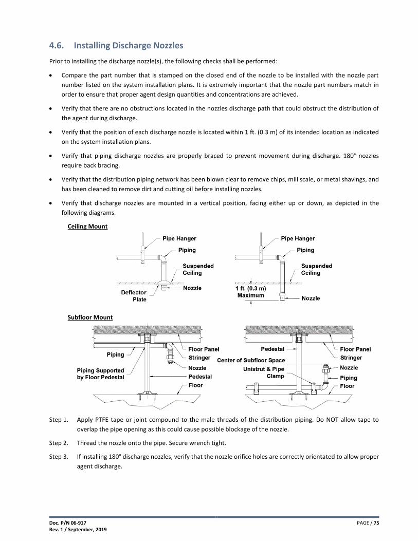
Doc. P/N 06-917 Rev. 1 / September, 2019
PAGE / 75
4.6. Installing Discharge Nozzles
Prior to installing the discharge nozzle(s), the following checks shall be performed:
Compare the part number that is stamped on the closed end of the nozzle to be installed with the nozzle part
number listed on the system installation plans. It is extremely important that the nozzle part numbers match in
order to ensure that proper agent design quantities and concentrations are achieved.
Verify that there are no obstructions located in the nozzles discharge path that could obstruct the distribution of
the agent during discharge.
Verify that the position of each discharge nozzle is located within 1 ft. (0.3 m) of its intended location as indicated
on the system installation plans.
Verify that piping discharge nozzles are properly braced to prevent movement during discharge. 180° nozzles
require back bracing.
Verify that the distribution piping network has been blown clear to remove chips, mill scale, or metal shavings, and
has been cleaned to remove dirt and cutting oil before installing nozzles.
Verify that discharge nozzles are mounted in a vertical position, facing either up or down, as depicted in the
following diagrams.
Ceiling Mount
Subfloor Mount
Step 1. Apply PTFE tape or joint compound to the male threads of the distribution piping. Do NOT allow tape to
overlap the pipe opening as this could cause possible blockage of the nozzle.
Step 2. Thread the nozzle onto the pipe. Secure wrench tight.
Step 3. If installing 180° discharge nozzles, verify that the nozzle orifice holes are correctly orientated to allow proper
agent discharge.

PAGE / 76 Doc. P/N 06-917 Rev. 1 / September, 2019
4.7. Installing System Actuation Components
Prior to installing system actuation components, the electrical control system must be thoroughly checked out to verify
that there are no issues present on the system that could accidentally cause inadvertent activation of the suppression
system. Installation of the system actuation components should be the last item completed before the system is placed
into service.
4.7.1. Installing Impulse Valve Operator (IVO)
Step 1. Check to ensure that the Impulse Valve Operator (IVO) is armed (firing pin retracted) and the safety pin is in
place.
CAUTION: Do NOT install the IVO to the container with the firing pin extended as this may cause accidental
discharge.
Step 2. Install conduit (rigid or flexible) from the Impulse Release Module (IRM) electrical box to the IVO. The IVO is
equipped with ½” NPT female threads for conduit connection.
Step 3. Pull the IVO wire leads through the conduit.
Step 4. Connect the IVO wire leads to the IRM. See 4.7.1.1.
Step 5. Remove the plug from the container’s actuator port. Keep for future use should the container have to be
removed for service.
Step 6. Insert the IVO into the actuator port and secure in place with the IVOS retaining clip. See 4.7.4.
The container is now armed.
Disarmed
Armed
NOTE: An IVOS must be installed to supervise the connection of an IVO to a container.
See Section 3.10 for specific details on the various system activation methods using the IVO.
Impulse Valve
Operator (IVO)
Actuator Port
Impulse Valve
Operator
Supervisor (IVOS)

Doc. P/N 06-917 Rev. 1 / September, 2019
PAGE / 77
4.7.1.1. Impulse Valve Operator (IVO) Wiring
The IVO is wired to an Impulse Release Module (IRM), which is connected to a compatible Fike releasing panel (SHP-Pro or Cheetah Xi). Refer to Fike document 06-552 for IRM wiring details
Impulse Valve Operator Wiring Diagram
4.7.2. Installing Impulse Energetic Actuator (IEA)
Step 1. Check to ensure that the IEA firing pin is retracted (i.e., flush with actuator body).
CAUTION: Do NOT install the IEA to the container with the firing pin extended as this indicates that the IEA has been
activated and must be replaced. Installing the IEA with the firing pin extended may cause accidental
discharge.
Step 2. Install conduit (rigid or flexible) from the Impulse Release Module (IRM) electrical box to the IEA. The IEA
adapter body provides a connection point for ½” rigid conduit compression fitting.
Step 3. Pull the IEA wire leads through the conduit.
Step 4. Connect the IEA wire leads to the IRM. See 4.7.2.1.
Step 5. Remove the retaining clip and plug from the container’s actuator port. Keep these items for future use should
the container have to be removed for service.
Step 6. Insert the IEA into the actuator port and secure in place with the IVOS retaining clip. See Section 4.7.4.
The container is now armed.
Disarmed
Armed
NOTE: An IVOS must be installed to supervise the connection of the IEA to each container.
See Section 3.10 for specific details on the various system activation methods using the IEA.
Impulse Energetic
Actuator (IEA)
Actuator Port
Impulse Valve
Operator
Supervisor (IVOS)

PAGE / 78 Doc. P/N 06-917 Rev. 1 / September, 2019
4.7.2.1. Impulse Energetic Actuator (IEA) Wiring
The IEA is wired to an Impulse Release Module (IRM), which is connected to a compatible Fike releasing panel (SHP-Pro or Cheetah Xi). Refer to Fike document 06-552 for IRM wiring details
Impulse Energetic Actuator Wiring Diagram
4.7.3. Installing Impulse Valve Pneumatic Operator (IVPO)
Step 1. Check to ensure that the Impulse Valve Pneumatic Operator (IVPO) is armed (firing pin retracted).
CAUTION: Do NOT install the IVPO to the container with the firing pin extended as this may cause accidental
discharge.
Step 2. Apply PTFE tape to the male threads of the adapter. Do NOT allow tape to overlap the end of the adapter as
this could cause possible blockage of the pressure port.
Step 3. Screw the R1/8 x ¼ JIC adapter into the threaded port on the IVPO. Secure wrench tight.
Step 4. Screw one end of the pilot line hose supplied with the IVPO to the ¼ JIC end of the adapter installed in Step 3.
Secure wrench tight.
Step 5. Connect the other end of the pilot line hose to the pilot line tubing from the previous container or nitrogen
actuator assembly. See Section 3.10 for specific details on the various system activation methods using the
IVPO.
Step 6. Remove the retaining clip and plug from the container’s actuator port. Keep the plug for future use should
the container have to be removed for service.
Step 7. Insert the IVPO into the actuator port and secure in place with the IVOS retaining clip. See Section 4.7.4.
The container is now armed.
Disarmed
Armed
NOTE: An IVOS must be installed to supervise the connection of the IVPO to each container.
1/8” x ¼” JIC
Adapter
¼” JIC x 3 ft. (0.9 m)
Long Actuation
Hose
Impulse Valve
Pneumatic
Operator (IVPO)
Actuator Port Impulse Valve
Operator
Supervisor (IVOS)

Doc. P/N 06-917 Rev. 1 / September, 2019
PAGE / 79
4.7.4. Installing Impulse Valve Operator Supervisor (IVOS)
Step 1. Connect the IVOS to the electrical box using the electrical connector integrated into the IVOS.
Step 2. Connect the IVOS wire leads to a “Supervisory” input on a Fike releasing panel. See 4.7.4.1.
Step 3. Install the actuator (IVO, IEA or IVPO) into the valve actuator port.
Step 4. Position the IVOS so the retaining pins are facing the valve, as shown below.
Step 5. Align the IVOS retaining pins with the holes provided in the valve actuator port.
Step 6. Gently squeeze the IVOS retaining pins together and insert them into the holes provided in the actuator port
body until the IVOS is fully seated.
Step 7. Verify that the IVOS pushbutton switch is fully depressed and that the actuator is securely held in place.
Impulse Valve Operator Supervisor (IVOS) Installation to Cylinder Valve
4.7.4.1. Impulse Valve Operator Supervisor (IVOS) Wiring
The IVOS is wired to a “Supervisory” input on the compatible Fike releasing panel (SHP-Pro or Cheetah Xi). Refer to the appropriate control panel manual for further information.
Impulse Valve Operator Supervisor Wiring Diagram
Impulse Actuator
Actuator Port
Impulse Valve
Operator
Supervisor (IVOS)
Retaining Pins Facing
Container Valve

PAGE / 80 Doc. P/N 06-917 Rev. 1 / September, 2019
4.7.5. Installing Nitrogen Actuator Assembly
Prior to installing the Nitrogen Actuator Assembly, the following items shall be verified.
The Nitrogen Actuator Assembly should be the last component installed on the system.
Verify that the location for installing the Nitrogen Actuator Assembly is suitably protected so that it is not subject
to mechanical, chemical, or other damage that would render it inoperable.
Verify that the location for installing the Nitrogen Actuator Assembly is easily accessible at all times, including at the time of a fire.
When used as a Primary Actuator, verify that signage has been installed to identify the hazard that each Nitrogen Actuator Assembly serves.
Step 1. Use the Nitrogen Actuator Assembly mounting bracket as a template to mark and drill the mounting holes.
NOTE: When using a Universal Valve Operator (UVO) with manual strike button to activate the Nitrogen Actuator
Assembly, the UVO strike button shall NOT be located greater than 4 ft. (1.2 m) above the floor.
Step 2. Secure the Nitrogen Actuator Assembly to the mounting surface using suitable anchors, provided by others.
Step 3. Attach the chosen actuator (UVO, UEA or Pneumatic Relay) to the Nitrogen Actuator Assembly valve following
the steps indicated in Sections 4.7.6, 4.7.7, and 4.7.8.
Nitrogen Actuator Assembly (Without Actuator)
See Section 3.10 for specific details on the various system activation methods using the Nitrogen Actuator Assembly.

Doc. P/N 06-917 Rev. 1 / September, 2019
PAGE / 81
4.7.6. Installing UVO Primary Completer Kit (P/N 70-335)
See the following page for an assembly drawing of the Nitrogen Actuator Assembly with UVO Primary Completer Kit.
Step 1. Apply PTFE tape to the NPT male threads of item 7, item 8, item 9, and item 12. Do NOT allow tape to overlap
the end of the fitting as this could cause possible blockage of the pressure port.
Step 2. Assemble item 7, item 8, and item 12 together. Secure wrench tight.
Step 3. Remove item 5 from item 4. Retain for future use.
Step 4. Screw the items assembled in Step 2 into the threaded port on item 4. Secure wrench tight. Orient the assembly
so the side outlet of item 8 is positioned horizontally.
Step 5. Screw item 9 into the side outlet of item 8. Secure wrench tight.
Step 6. Install item 10 onto item 9.
Step 7. Screw item 11 onto item 9. Secure wrench tight.
Step 8. Connect one end of item 13 to item 12. Secure wrench tight.
Step 9. Connect the other end of item 13 to the pilot line tubing (not shown). Secure wrench tight.
Step 10. Check to ensure that item 4 is armed (firing pin retracted).
CAUTION: Do NOT install the UVO to the container with the firing pin extended as this may cause accidental
discharge.
Step 11. Connect item 4 wire leads to the host control panel or module. See 4.7.6.1.
Step 12. Connect item 6 wire leads to the host control panel or module. See 4.7.9.1.
Step 13. Remove item 2 and item 3 from item 1. Keep these items for future use should the container have to be
removed for service.
Step 14. Connect item 4 to item 1 and secure in place with item 6. See 4.7.9.
CAUTION: Installation of the system actuation components should be the last item completed before the system is
placed into service.
The Nitrogen Actuator is now armed.

PAGE / 82 Doc. P/N 06-917 Rev. 1 / September, 2019
Nitrogen Actuator Assembly with UVO Primary Completer Kit
Item No.
Part Number
Description Notes
1 70-325-X Nitrogen Actuator Assembly Part of 70-325 Nitrogen Actuator Assembly
2 02-11755 Retaining Clip
3 IG71-0151 Valve Fill Adapter Plug
4 02-13571 Universal Valve Operator (UVO)
Part of 70-335 Primary Completer Kit
5 02-14053 Pipe Plug
6 02-14627 Universal Valve Operator Supervisory (UVOS)
7 02-13640 1/8 in. NPT x 1/4 in. NPT Adapter
8 C02-1335 1/4 in. Street Tee
9 02-11766 1/4 in. NPT x G1/4 Adapter
10 02-10926 1/4 in. Sealing Washer
11 IG71-026 Vent Valve Assembly
12 02-4530 1/4 in. NPT x 1/4 in. JIC Adaptor
13 02-4977 1/4 in. JIC x 36 in. (0.9 m) Long Actuation
4.7.6.1. Universal Valve Operator (UVO) Wiring
The UVO is wired directly to the releasing circuit of a Fike releasing panel (SHP-Pro or Cheetah Xi) and MUST not be connected to an Impulse Release Module (IRM). Refer to the appropriate control panel manual for further information.
Universal Valve Operator Wiring Diagram
CAUTION: If the UVO is to be connected to a Fike Cheetah Xi Releasing Control Module, a Solenoid Supervision and Protection Assembly (P/N 10-2360) must be installed. Refer to Fike document 06-344.

Doc. P/N 06-917 Rev. 1 / September, 2019
PAGE / 83
4.7.7. Installing UEA Primary Completer Kit (P/N 70-400)
See the following page for an assembly drawing of the Nitrogen Actuator Assembly with UEA Primary Completer Kit.
Step 1. Apply PTFE tape to the NPT male threads of item 7, item 8, item 9, and item 12. Do NOT allow tape to overlap
the end of the fitting as this could cause possible blockage of the pressure port.
Step 2. Assemble item 7, item 8, and item 12 together. Secure wrench tight.
Step 3. Remove item 5 from item 4. Retain for future use.
Step 4. Screw the items assembled in Step 2 into the threaded port on item 4. Secure wrench tight. Orient the
assembly so the side outlet of item 8 is positioned horizontally.
Step 5. Screw item 9 into the side outlet of item 8. Secure wrench tight.
Step 6. Install item 10 onto item 9.
Step 7. Screw item 11 onto item 9. Secure wrench tight.
Step 8. Connect one end of item 13 to item 12. Secure wrench tight.
Step 9. Connect the other end of item 13 to the pilot line tubing (not shown). Secure wrench tight.
Step 10. Check to ensure that item 4 is armed (firing pin retracted).
CAUTION: Do NOT install the UEA to the container with the firing pin extended as this may cause accidental
discharge.
Step 11. Connect item 4 wire leads to the host control panel or module. See 4.7.7.1.
Step 12. Connect item 6 wire leads to the host control panel or module. See 4.7.9.1.
Step 13. Remove item 2 and item 3 from item 1. Keep these items for future use should the container have to be
removed for service.
Step 14. Connect item 4 to item 1 and secure in place with item 6. See 4.7.9.
CAUTION: Installation of the system actuation components should be the last item completed before the system is
placed into service.
The Nitrogen Actuator is now armed.

PAGE / 84 Doc. P/N 06-917 Rev. 1 / September, 2019
Nitrogen Actuator Assembly with UEA Primary Completer Kit
Item No.
Part Number
Description Notes
1 70-325-X Nitrogen Actuator Assembly Part of 70-325 Nitrogen Actuator Assembly
2 02-11755 Retaining Clip
3 IG71-0151 Valve Fill Adapter Plug
4 IG71-247 Universal Energetic Actuator (UEA)
Part of 70-400 Primary Completer Kit
5 02-14053 Pipe Plug
6 02-14627 Universal Valve Operator Supervisory (UVOS)
7 02-13640 1/8 in. NPT x 1/4 in. NPT Adapter
8 C02-1335 1/4 in. Street Tee
9 02-11766 1/4 in. NPT x G1/4 Adapter
10 02-10926 1/4 in. Sealing Washer
11 IG71-026 Vent Valve Assembly
12 02-4530 1/4 in. NPT x 1/4 in. JIC Adaptor
13 02-4977 1/4 in. JIC x 36 in. (0.9 m) Long Actuation Hose
14 10-2748 Impulse Releasing Module (IRM), not shown
4.7.7.1. Universal Energetic Actuator (UEA) Wiring
The UEA is wired to an Impulse Release Module (IRM), which is connected to a compatible Fike releasing panel (SHP-Pro or Cheetah Xi). Refer to Fike document 06-552 for IRM wiring details
Universal Energetic Actuator Wiring Diagram

Doc. P/N 06-917 Rev. 1 / September, 2019
PAGE / 85
4.7.8. Installing Pneumatic Relay Secondary Completer Kit (P/N 70-336)
See the following page for an assembly drawing of the Nitrogen Actuator Assembly with Pneumatic Relay Secondary Completer Kit.
Step 1. Apply PTFE tape to the G1/4 male threads of item 3. Do NOT allow tape to overlap the end of the fitting as
this could cause possible blockage of the pressure port.
Step 2. Connect item 3 to item 2A. Secure wrench tight.
Step 3. Connect the other end of item 3 to the pilot line tubing (not shown). Secure wrench tight.
Step 4. Check to ensure that item 2A is armed (firing pin retracted).
CAUTION: Do NOT install the pneumatic relay to the container with the firing pin extended as this may cause
accidental discharge.
Step 5. Remove item 1C and item 1B from item 1A. Keep these items for future use should the container have to be
removed for service.
Step 6. Connect item 2A to item 1A and secure in place with item 1C.
CAUTION: Installation of the system actuation components should be the last item completed before the system is
placed into service.
Step 7. Connect free end of item 2C to the pilot line, IVPO or selector valve. Secure wrench tight.
Step 8. Install pilot line vent components (items 5 thru 8) as shown in Section 4.3.6.2 or 4.8.4.
The Nitrogen Actuator is now armed.

PAGE / 86 Doc. P/N 06-917 Rev. 1 / September, 2019
Nitrogen Actuator Assembly with Pneumatic Relay Secondary Completer Kit
Item No.
Part Number
Description Notes
1A 70-325-X Nitrogen Actuator Assembly Part of 70-325 Nitrogen Actuator Assembly
1B IG71-0151 Valve Fill Adapter Plug
1C 02-11755 Retaining Clip
2A 70-334 Pneumatic Relay Assembly Part of 70-334 Pneumatic Relay Assembly
2B 02-11243 R1/8 in. x 1/4 in. JIC Hex Nipple
2C 02-4977 1/4 in. JIC x 36 in. (0.9 m) Long Actuation
3 02-10801 G1/4 x 1/4 in. JIC x 39 in (1 m) Long Actuation
Hose Ordered separately
4 02-14721 1/4 in. JIC x 1/4 in. FNPT Branch Tee
5 02-11346 1/4 in. JIC Coupling, Swivel
6 02-11766 1/4 in. NPT x G1/4 Adapter
7 02-10926 1/4 in. Sealing Washer
8 IG71-026 Vent Valve Assembly

Doc. P/N 06-917 Rev. 1 / September, 2019
PAGE / 87
4.7.9. Installing Universal Valve Operator Supervisor (UVOS)
Step 1. Connect the UVOS to the electrical box using the electrical connector integrated into the UVOS.
Step 2. Connect the UVOS wire leads to a “Supervisory” input on a Fike releasing panel. See 4.7.9.1.
Step 3. Install the actuator (UVO, UEA or Pneumatic Relay) into the valve actuator port.
Step 4. Position the UVOS so the retaining pins are facing the brass valve, as shown below.
Step 5. Align the UVOS retaining pins with the holes provided in the valve actuator port.
Step 6. Gently squeeze the UVOS retaining pins together and insert them into the holes provided in the actuator port
body until the UVOS is fully seated.
Step 7. Verify that the UVOS pushbutton switch is fully depressed and that the actuator is securely held in place.
Universal Valve Operator Supervisor (UVOS) Installation to Nitrogen Actuator
4.7.9.1. Universal Valve Operator Supervisor (UVOS) Wiring
The UVOS is wired to a “Supervisory” input on the compatible Fike releasing panel (SHP-Pro or Cheetah Xi). Refer to the appropriate control panel manual for further information.
Universal Valve Operator Supervisor Wiring Diagram
Nitrogen Actuator
Universal Valve
Operator
Impulse Valve
Operator
Supervisor (IVOS)
Plug
Retaining Clip
Retaining Pins
Facing Container
Valve

PAGE / 88 Doc. P/N 06-917 Rev. 1 / September, 2019
4.8. Installing Pneumatic Actuation Lines
Pneumatic actuation lines are used to allow simultaneous pneumatic activation of multiple containers. Pneumatic
actuation lines shall be installed in a manner that protects them against crimping or mechanical damage. Where the
pneumatic actuation line could be exposed to conditions that could lead to loss of integrity, special precautions shall be
taken to ensure that no loss of integrity will occur. Pneumatic actuation lines shall be secured to a solid surface.
Anchoring into plaster, sheetrock wall or any other facing material is NOT acceptable.
4.8.1. Two Containers with IVO and IVPO
Step 1. Apply PTFE tape or thread sealant to all items (parts) equipped male NPT threads. Do NOT allow tape or
sealant to overlap end of fitting.
Step 2. Assemble items as shown in the diagram below. Secure wrench tight.
Step 3. Remove 1/4” NPT plug from the primary container’s adapter nipple and thread item 5 into port. Secure
wrench tight.
Step 4. Connect system actuation components (IVO, IEA, IVPO) to the containers. See Section 4.7 for details.
The containers are now armed.
Maximum Two Containers Connected to Fike Releasing Panel
Pilot Line Limitations: 1) Pilot line hoses supplied by Fike.
Item No.
Part Number Description Notes
1A 02-12728 Impulse Valve Operator (IVO)* Part of 70-279 Kit
1B 70-374 Impulse Energetic Actuator (IEA) Part of 70-390 Kit
2 02-12729 Impulse Valve Pneumatic Operator (IVPO)
Part of 70-280 IVPO Kit 2A 02-4535 1/8 in. NPT x 1/4 in. JIC Adaptor
2B 02-4977 1/4 in. JIC x 36 in. (0.9 m) Long Actuation Hose
3 02-12926 1/4 in. JIC Male Adaptor
4 02-4977 1/4 in. JIC x 36 in. (0.9 m) Long Actuation Hose
5 02-4530 1/4 in. NPT x 1/4 in. JIC Adaptor
* The IVO shown can be replaced with a IEA (Item 1B); however, there is no strike button provided on the IEA to permit mechanical manual
activation of the container. Electric manual activation must be used to manually activate the container.

Doc. P/N 06-917 Rev. 1 / September, 2019
PAGE / 89
4.8.2. Multiple Containers with IVO and IVPO
Step 1. Install pneumatic tubing between the containers. See pilot line limitations below. Terminate tubing within 2
feet (0.61 m) of the container valve.
Step 2. Apply PTFE tape or thread sealant to all items (parts) equipped male NPT threads. Do NOT allow tape or
sealant to overlap end of fitting.
Step 3. Assemble items as shown in the diagram below. Secure wrench tight.
Step 4. Remove ¼” NPT plug from the primary container’s adapter nipple and thread item 9 into port. Secure wrench
tight.
Step 5. Connect system actuation components (IVO, IEA, IVPO) to the containers. See Section 4.7 for details.
The containers are now armed.
Maximum Seven Containers Connected to Fike Releasing Panel
Pilot Line Limitations: 1) Maximum 50 ft. (15.2 m) total length including hoses. 2) Tubing (supplied by others) shall be 1/4 in. x 0.035 in. wall stainless steel. 3) Pilot line hoses supplied by Fike.
Item No.
Part Number Description Notes
1A 02-12728 Impulse Valve Operator (IVO)* Part of 70-279 Kit
1B 70-374 Impulse Energetic Actuator (IEA) Part of 70-390 Kit
2 02-12729 Impulse Valve Pneumatic Operator (IVPO)
Part of 70-280 IVPO Kit 2A 02-4535 1/8 in. NPT x 1/4 in. JIC Adaptor
2B 02-4977 1/4 in. JIC x 36 in. (0.9 m) Long Actuation Hose
3 C02-1356 1/4 in. Male JIC x 1/4 in. Male Tube Adaptor
4 02-12696 1/4 in. Tube 90° Elbow
5 N/A 1/4 in. x 0.035 in. Wall, Stainless Steel Tubing Supplied by others
6 C02-1359 1/4 in. Tube Tee
7 02-12695 1/4 in. Tube x 1/4 in. JIC Adaptor
8 02-4977 1/4 in. JIC x 36 in. (0.9 m) Long Actuation Hose
9 02-4530 1/4 in. NPT x 1/4 in. JIC Adaptor
* The IVO shown can be replaced with a IEA (Item 1B); however, there is no strike button provided on the IEA to permit mechanical manual
activation of the container. Electric manual activation must be used to manually activate the container.

PAGE / 90 Doc. P/N 06-917 Rev. 1 / September, 2019
4.8.3. Multiple Containers with Primary Nitrogen Actuator
Step 1. Install Nitrogen Actuator Assembly (item 1). See sections 4.7.5 for installation instructions.
Step 2. Install pneumatic tubing between the containers and the nitrogen actuator. See pilot line limitations below.
Terminate tubing within 2 feet (0.61 m) of the container valve and nitrogen actuator.
Step 3. Apply PTFE tape or thread sealant to all items (parts) equipped male NPT threads. Do NOT allow tape or sealant
to overlap end of fitting.
Step 4. Assemble items as shown in the diagram below. Secure wrench tight.
Step 5. Install the UVO or UEA primary completer kit to the nitrogen actuator. See Sections 4.7.6 or 4.7.7 for installation
instructions.
Step 6. Connect IVPO to the containers. See Section 4.7 for details.
The containers are now armed.
Maximum Five Containers Connected to Primary Nitrogen Actuator
Pilot Line Limitations: 1) Minimum 100 ft. (30.5 m) between Primary Nitrogen Actuator and first IVPO. 2) Maximum 300 ft. (91.5 m) between Primary Nitrogen Actuator and last IVPO. 3) Maximum 160 ft. (48.8 m) between first and last IVPO. 4) Maximum of six IVPOs can be activated by the Primary Nitrogen Actuator. 5) Tubing (supplied by others) shall be 1/4 in. x 0.035 in. wall stainless steel. 6) Pilot line hoses supplied by Fike.
See next page for a description of numerical callouts shown in the diagram above.

Doc. P/N 06-917 Rev. 1 / September, 2019
PAGE / 91
Item No.
Part Number Description Notes
1 70-325-X Nitrogen Actuator Assembly
2A 02-13571 Universal Valve Operator (UVO)* Part of 70-335 Primary Completer Kit
2B IG71-247 Universal Energetic Actuator (UEA) Part of 70-400 Primary Completer Kit
2C 02-13640 1/8 in. NPT x 1/4 in. NPT Adapter
Part of Primary Completer Kit (Item 2A or 2B)
2D C02-1335 1/4 in. Street Tee
2E 02-4530 1/4 in. NPT x 1/4 in. JIC Adaptor
2F 02-11766 1/4 in. NPT x G1/4 Adapter
2G 02-10926 1/4 in. Sealing Washer
2H IG71-026 Vent Valve Assembly
2J 02-4977 1/4 in. JIC x 36 in. (0.9 m) Long Actuation Hose
3 02-12729 Impulse Valve Pneumatic Operator (IVPO)
Part of 70- 280 IVPO Kit 3A 02-4535 1/8 in. NPT x 1/4 in. JIC Adaptor
3B 02-4977 1/4 in. JIC x 36 in. (0.9 m) Long Actuation Hose
4 C02-1356 1/4 in. Male JIC x 1/4 in. Male Tube Adaptor
5 02-12696 1/4 in. Tube 90° Elbow
6 N/A 1/4 in. x 0.035 in. Wall, Stainless Steel Tubing Supplied by others
7 C02-1359 1/4 in. Tube Tee
8 02-12695 1/4 in. Tube x 1/4 in. JIC Adaptor
* The UVO shown can be replaced with a UEA (Item 2B); however, there is no strike button provided on the IEA to permit mechanical manual
activation of the container. Electric manual activation must be used to manually activate the container.

PAGE / 92 Doc. P/N 06-917 Rev. 1 / September, 2019
4.8.4. Multiple Containers with Primary and Secondary Nitrogen Actuators
Step 1. Install Nitrogen Actuator Assemblies. See Sections 4.7.5 for installation instructions.
Step 2. Install pneumatic tubing between the containers and the nitrogen actuators. See pilot line limitations below.
Terminate tubing within 2 feet (0.61 m) of the container valve and nitrogen actuators.
Step 3. Apply PTFE tape or thread sealant to all items (parts) equipped male NPT threads. Do NOT allow tape or
sealant to overlap end of fitting.
Step 4. Assemble items as shown in the diagram below, wrench tight.
Step 5. Install the UVO, UEA or relay actuator completer kit to the nitrogen actuator. See Sections 4.7.6, 4.7.7 or 4.7.8
for installation instructions.
Step 6. Connect IVPO to the containers. See Section 4.7 for details.
The containers are now armed.
Maximum Five Containers Connected to Primary and Secondary Nitrogen Actuators
Pilot Line Limitations: 1) Maximum 150 ft. (45 m) between Primary Nitrogen Actuator and Secondary Nitrogen Actuator. 2) Minimum 100 ft. (30.5 m) between Secondary Nitrogen Actuator and first IVPO. 3) Maximum 300 ft. (91.5 m) between Secondary Nitrogen Actuator and last IVPO. 4) Maximum 160 ft. (48.8 m) between first and last IVPO. 5) Maximum of six IVPOs can be activated by the Secondary Nitrogen Actuator. 6) Tubing (supplied by others) shall be 1/4 in. x 0.035 in. wall stainless steel. 7) Pilot line hoses supplied by Fike.
See next page for description of numerical callouts shown in the diagram above.

Doc. P/N 06-917 Rev. 1 / September, 2019
PAGE / 93
Item No.
Part Number Description Notes
1 70-325-X Nitrogen Actuator Assembly
2A 02-13571 Universal Valve Operator (UVO)* Part of 70-335 Primary Completer Kit
2B IG71-247 Universal Energetic Actuator (UEA) Part of 70-400 Primary Completer Kit
2C 02-13640 1/8 in. NPT x 1/4 in. NPT Adapter
Part of Primary Completer Kit (Item 2A or 2B)
2D C02-1335 1/4 in. Street Tee
2E 02-4530 1/4 in. NPT x 1/4 in. JIC Adaptor
2F 02-11766 1/4 in. NPT x G1/4 Adapter
2G 02-10926 1/4 in. Sealing Washer
2H IG71-026 Vent Valve Assembly
2J 02-4977 1/4 in. JIC x 36 in. (0.9 m) Long Actuation Hose
3 02-12729 Impulse Valve Pneumatic Operator (IVPO)
Part of 70- 280 IVPO Kit 3A 02-4535 1/8 in. NPT x 1/4 in. JIC Adaptor
3B 02-4977 1/4 in. JIC x 36 in. (0.9 m) Long Actuation Hose
4 02-14721 1/4 in. JIC x 1/4 in. FNPT Branch Tee
5 02-11346 1/4 in. JIC Coupling
6 C02-1356 1/4 in. Male JIC x 1/4 in. Male Tube Adaptor
7 02-12696 1/4 in. Tube 90° Elbow
8 N/A 1/4 in. x 0.035 in. Wall, Stainless Steel Tubing Supplied by others
9 C02-1359 1/4 in. Tube Tee
10 02-12695 1/4 in. Tube x 1/4 in. JIC Adaptor
11 70-325-X Nitrogen Actuator Assembly
12 IG71-120 Pneumatic Relay
Part of 70-334 Pneumatic Relay Assembly
12A 02-11243 R1/8 in. x 1/4 in. JIC Hex Nipple
12B 02-4977 1/4 in. JIC x 36 in. (0.9 m) Long Actuation Hose
13 02-10801 G1/4 x 1/4 in. JIC x 39 in. (1 m) Long Actuation Hose
* The UVO shown can be replaced with a UEA (Item 2B); however, there is no strike button provided on the IEA to permit mechanical manual
activation of the container. Electric manual activation must be used to manually activate the container.

PAGE / 94 Doc. P/N 06-917 Rev. 1 / September, 2019
5. ACCEPTANCE TESTING
The completed system shall be reviewed and tested by qualified personnel that have knowledge and experience of the
testing requirements contained in this manual and NFPA 2001. Testing personnel shall follow all safety procedures
during system testing. The following acceptance testing procedures are intended to represent the minimum
requirement for the extinguishing portion of the system. Additional testing may be required by the AHJ.
If the system is connected to an alarm receiving office, notify the alarm receiving office that a fire system test is to be conducted and that emergency response by the fire department or alarm station personnel is not required. Notify all personnel in the areas that could be affected by the testing that a test is to be conducted and instruct them as to the events that could occur during the test.
CAUTION: The releasing mechanism on each storage container or nitrogen actuator must be disconnected from the
container prior to conducting the acceptance test in order to prevent activation of the suppression system
during testing.
5.1. Pre-Checks and Visual Inspections
When the installation is complete and before making the final connections, the following system checks should be made:
Enclosure Checks
____ 1. Check the hazard area dimensions against those shown on the system plan(s). If the area volume has changed, the agent weight should be recalculated and compared with the agent weight supplied.
____ 2. Check the hazard area for walls or movable partitions that may have been added or changed. If walls or partitions have been added, check to see that all areas within the hazard still receive adequate nozzle coverage and agent distribution.
____ 3. Thoroughly examine the enclosure to verify that it has been properly constructed and sealed to eliminate any significant air leaks that could result in failure of the enclosure to hold the agent concentration.
____ 4. Perform an Enclosure Integrity Test on all protected enclosures. A Door Fan Test is the accepted method to estimate worst-case room leakage and agent (concentration) hold time. Refer to NFPA Standard 2001, latest edition for additional information and door fan test procedures.
Mechanical Checks
____ 1. Inspect the piping distribution system(s) to verify that it has been installed in compliance with the design drawings. Nozzle locations, nozzle orientation, pipe sizes, pipe size reductions and orientation of tees shall be checked against the design drawings. If piping system as installed differs from the design drawings, the system MUST be recalculated to reflect the piping system as installed.
____ 2. Visually inspect all components for signs of damage (i.e., corrosion, dents, twisted, etc.).
____ 3. Check that all agent storage containers are properly located in accordance with the design drawings
____ 4. Check that all agent storage containers are securely fastened with supplied brackets.
____ 5. Check that all piping joints, discharge nozzles, and piping supports are securely fastened to prevent unacceptable vertical or lateral movement during discharge.
____ 6. Check that all warning and instruction signs are mounted where required.

Doc. P/N 06-917 Rev. 1 / September, 2019
PAGE / 95
____ 7. Check that all nozzles are the proper type, correctly placed in accordance with the design drawings, and properly oriented. Make certain there are no obstructions that could block the discharge of agent from the nozzle(s).
____ 8. Make sure all nozzle set screws are in place.
____ 9. Check the container gauge to confirm container pressure is in operable range. Pressure should read 500 PSIG at 70°F (34.5 BAR at 21°C). For temperatures other than 70°F (21°C), reference Temperature vs. Pressure Chart on Page 9.
____ 10. Check the model and agent weight markings on the container nameplate to verify that the correct container has been installed in accordance with the design drawings.
____ 11. Verify the amount of agent in the container(s) by either weighing the container or by using the container’s Liquid Level Indictor (LLi), if installed. This information should be recorded and affixed to the container so it can be used during container maintenance.
____ 12. Verify the operation of auxiliary functions such as door closures, damper closures, air handling shutdown, etc. should be verified when the control system is activated, both manually and automatically.
____ 13. Verify that the Low Pressure Switch (if installed) is properly secured to the container and wired properly to control panel.
____ 14. Check the system actuators (IVO, IEA or Nitrogen Actuator) are disconnected from the suppression containers or pneumatic actuation lines to prevent false activation of the system.
____ 15. Check all pipe joints for mechanical tightness.
____ 16. Perform a pressure test on the piping network in accordance with NFPA 2001, latest edition.
____ 17. Verify that all check valves (if used) are installed with the “Flow Arrow” pointing in the correct direction.
Pneumatic Checks
Where pneumatic system actuation components are used (i.e., IVPO, Nitrogen Actuator Assembly), the following pneumatic checks should be made:
____ 1. Remove all Impulse Valve Pneumatic Operators (IVPO) from container valves.
____ 2. Disconnect actuation hose from the master container valve or Nitrogen Actuator Assembly.
____ 3. Provide 100 psi (6.9 bar) pressure to the disconnected actuation hose.
____ 4. Verify all IVPOs are in the fired (piston extended) position. Reset IVPO(s) upon completion of testing.
Electrical Checks
The information contained in this document does not cover service and maintenance procedures for the Detection and Control System (electrical portion). The electrical portion of the system must be thoroughly checked out according to the manufacturer's recommendations and the requirements of the AHJ.
IMPORTANT NOTE: Do not arm the Fike Clean Agent Fire Suppression system before the Detection and Control
System has been checked out and all circuits are free of trouble and ground fault conditions. If
control panel checks out, install the releasing mechanism to the container(s).
The results of the system checkout shall be documented in a test report. The test report shall be maintained by the system owner for the life of the suppression system.

PAGE / 96 Doc. P/N 06-917 Rev. 1 / September, 2019
6. MAINTENANCE
The completed system shall be maintained by qualified personnel that have knowledge and experience of the maintenance and service requirements contained in this manual and NFPA 2001. Testing personnel shall follow all safety procedures during system testing. The following maintenance procedures are intended to represent the minimum requirement for the extinguishing portion of the system. Additional maintenance procedures may be required by the AHJ.
IMPORTANT NOTE: This information does not cover maintenance procedures for the electrical and control portions
of the system. The control portion of the system should be thoroughly checked out according to
the manufacturer's recommendations and the requirements of the AHJ.
CAUTION: The releasing mechanism on each storage container must be disconnected from the container prior to
conducting the acceptance test in order to prevent activation of the suppression system container during
testing.
Monthly Inspection
____ 1. Check that the releasing panel is powered and is free of supervisory, trouble, or alarm conditions.
____ 2. Check that all manual controls (i.e., manual release, abort, pneumatic actuators, etc.) are unobstructed.
____ 3. Check that the system components show no signs of physical damage, corrosion or a condition that could prevent operation.
____ 4. Check all piping supports to make sure they are tight and all piping is properly supported.
____ 5. Check all nozzle orifices for signs of corrosion.
____ 6. Check all nozzles to make certain there are no obstructions that could block the discharge of agent from the nozzles.
____ 7. Check the container gauge to confirm container pressure is in operable range. Pressure should read 500 PSIG at 70°F (34.5 BAR at 21°C). In the range of 50°F to 80°F (10°C to 27°C), the difference is approximately 2 PSIG (15 kPa) per degree. For temperatures other than 70°F (21°C), reference Temperature vs. Pressure Chart on Page 9. If the pressure loss indicated exceeds 10% of the nominal pressure, check the container for leaks and repair as necessary.
____ 8. Check that the protected equipment or hazard area has not been changed or modified.
____ 9. Check that all penetrations made through the protected enclosure are properly sealed. Any new penetration shall be sealed immediately maintaining the original fire resistance rating of the enclosure.
____ 10. Verify that any previously noted deficiencies have been corrected.
If any deficiencies are found, appropriate corrective action shall be taken immediately. When the corrective action involves maintenance or repair, it shall be conducted by a qualified fire protection service technician.
Semiannual Inspection and Service
____ 1. Verify the amount of agent in the container(s) matches the agent weight stamped on the container label, by either weighing the container or by using the container’s Liquid Level Indictor (LLi), if installed. This information should be recorded and affixed to the container so it can be used during container maintenance. If the weight indicates a shortage exceeding 5% of required weight, the container must be removed from service for repair and/or recharge.

Doc. P/N 06-917 Rev. 1 / September, 2019
PAGE / 97
____ 2. Check the container gauge to confirm container pressure is in operable range. Pressure should read 500 PSIG at 70°F (34.5 BAR at 21°C). In the range of 50°F to 80°F (10°C to 27°C), the difference is approximately 2 PSIG (15 kPa) per degree. For temperatures other than 70°F (21°C), reference Temperature vs. Pressure Chart on Page 9. If the pressure loss indicated exceeds 10% of the nominal pressure, check the container for leaks and repair as necessary.
____ 3. The following information should be recorded and affixed to the container so it can be used during container maintenance.
a. Date of Inspection b. Person performing the inspection c. Type of agent d. Gross weight and net weight of container e. Container pressure and temperature
____ 4. Check the pressure gauge on the nitrogen actuator assembly valve (if applicable) to confirm cylinder pressure is in the operable range. Pressure should read 1800 psi at 70°F (124 bar at 21°C). Pressure may vary with temperature. If the pressure loss indicated exceeds 10% of the nominal pressure (adjusted for temperature), the cylinder must be recharged.
If any deficiencies are found, appropriate corrective action shall be taken immediately. When the corrective action involves maintenance or repair, it shall be conducted by a qualified fire protection service technician.
Annual Inspection and Service
____ 1. The checks listed in Section 5, Acceptance Testing should be performed.
____ 2. Check the hazard area dimensions against those shown on the system plan(s). If the area volume has changed, the agent weight should be recalculated and compared with the agent weight supplied to determine if the correct amount of agent is being supplied to protect the hazard.
____ 3. Thoroughly examine the enclosure to verify that the integrity of the enclosure has been maintained. Any
new penetrations into the enclosure have been properly sealed to eliminate any significant air leaks that
could result in failure of the enclosure to hold the agent concentration. If hazard conditions indicate the
inability to maintain the agent concentration, a door fan test should be performed in accordance with
NFPA 2001, latest edition.
If any deficiencies are found, appropriate corrective action shall be taken immediately. When the corrective action involves maintenance or repair, it shall be conducted by a qualified fire protection service technician.
5 Year Inspection and Service
____ 1. Perform a complete external visual inspection of each container in accordance with the Code of Federal Regulations, Title 49 and Compressed Gas Association (CGA) Pamphlet C-6, Section 3. The container does not need to be emptied or stamped while under pressure for this inspection. The inspection shall be performed by a CGA/DOT approved inspector only.
Where the external visual inspection indicates that the container has been damaged, addition strength tests shall be required.
____ 2. All hoses shall be detached from the system and a hydrostatic pressure test shall be performed in accordance with NFPA 2001, latest edition. Hoses failing the test must be marked and destroyed and replaced. Hoses passing the test shall be marked to show the date of test prior to reinstallation.
If any deficiencies are found, appropriate corrective action shall be taken immediately. When the corrective action involves maintenance or repair, it shall be conducted by a qualified fire protection service technician.

PAGE / 98 Doc. P/N 06-917 Rev. 1 / September, 2019
After System Discharge
____ 1. Recharge discharged containers. See Section 6.1 for instructions.
____ 2. Recharge discharged nitrogen actuator cylinders. See Section 6.2 for instructions.
____ 3. Replace damper in all 3-inch check valves. See Section 6.3 for instructions.
____ 4. Reset the actuators (IVO, IVPO, and UVO) where used. See Section 6.4 for instructions.
____ 5. Replace all Impulse Energetic Actuators (IEA) where used. The IEA is a single use device that MUST be replaced after system discharge.
____ 6. Reset Selector Valves, if applicable. See Section 6.5 for instructions.
6.1.
After a system discharge, it is imperative that the clean agent suppression containers be recharged and returned to
service as soon as possible (24 hours maximum) to ensure continued protection. Empty containers can be returned to
Fike for valve refurbishment and recharge or they can be sent to any Fike authorized Field Recharge Station. Containers
must be refurbished and recharged following the procedures outlined in the Clean Agent Recharge Manual, P/N 06-852.
Containers must be refilled with 3M™ Novec™ 1230 Fire Protection Fluid only.
For system recharge, contact you system installer or Fike’s Customer Service Department at +001-816-229-3405.
CAUTION: Under no circumstances should personnel, other than a Fike Authorized Service Representative, attempt to
disarm and remove a container for recharge.
The following procedure shall be used to recharge discharged containers.
____ 1. Use the main-reserve switch to engage the reserve agent supply, if provided.
____ 2. Remove the Impulse Valve Operator Supervisor (IVOS) and disconnect the actuator (i.e., IVO, IVPO, IEA) from the actuator port on the empty container(s).
____ 3. Disconnect and remove the Pressure Gauge from the container fill port on the empty container. Reinstall the threaded port plug retained during switch installation.
____ 4. Disconnect the empty container from the suppression piping.
____ 5. Remove the container from its mounting bracket or strap.
____ 6. Install the container baffle plate and safety shipping cap to prepare the container for shipping.
____ 7. Return the container to Fike or to an authorized container fill station for container rebuild and recharge. Refer to Fike document P/N 06-852 for container recharge procedure.
____ 8. Reinstall the recharged container making sure that the correct container is installed in the correct location.
____ 9. Reconnect the discharge piping to the recharged container.
____ 10. Reinstall the Pressure Gauge to the container fill port. See Section 4.4 for instructions.
____ 11. Reconnect the actuator (IVO, IVPO, IEA) to the valve actuator port. Make sure that the actuator has been reset or replaced, where applicable.
____ 12. Reinstall the IVOS to secure the actuator to the actuator port.

Doc. P/N 06-917 Rev. 1 / September, 2019
PAGE / 99
6.2.
____ 1. Disconnect the actuator (UVO, UEA or Pneumatic Relay) from the Nitrogen Actuator Assembly.
____ 2. Remove the Nitrogen Actuator Assembly from the mounting surface.
____ 3. Recharge the nitrogen cylinder. Refer to Nitrogen Actuator Recharge Manual 06-721 for recharge instructions.
____ 4. Reinstall the recharged Nitrogen Actuator Assembly to the mounting surface.
____ 5. Reconnect the actuator (UVO, UEA or Pneumatic Relay) to the Nitrogen Actuator Assembly. Make sure that the actuator has been reset or replaced, where applicable.
____ 6. Reinstall the IVOS to secure the actuator to the actuator port.
6.3. 3 Inch Check Valve Damper Replacement Procedure
IMPORTANT NOTE: This procedure only applies to the 3 inch check valves that have opened due to agent pressure.
Dampers DO NOT need to be replaced in 1 inch and 2 inch check valves.
The following procedure shall be used to replace the valve damper.
____ 1. Remove the check valve cap.
____ 2. Remove old damper.
____ 3. Insert new damper (P/N 70-322)
____ 4. Reinstall the check valve cap, wrench tight.
____ 5. Rearm the system after all 3 inch check valve dampers have been replaced.
3 Inch Check Valve (P/N 70-317)
3” Check Valve Cap Damper (P/N 70-322)

PAGE / 100 Doc. P/N 06-917 Rev. 1 / September, 2019
6.4. IVO, IVPO and UVO Reset Instructions
Reset Instructions using the 02-14782 Reset Multi Tool
1. Disconnect the valve operator from the Impulse Valve actuator port by removing the operator supervisor (IVOS or
UVOS) or retaining clip that secures the operator in place.
2. Remove the Safety Cotter Pin and pull the Manual Strike Button until a slight click is heard when the internal
components are realigned. This step does not apply to the IVPO.
3. Align the forked end of the anvil handle around the grooved end of the Operator tip.
4. Squeeze reset tool handles until Operator Pin resets (clicks into place); then, reinsert the Safety Pin. The operator is reset and
ready to be installed.
Operator
Pin Extended
(Fired Position)
Pull Knob
Safety Pin
Squeeze
Operator
Pin Reset
(Armed Position)
Safety Pin

Doc. P/N 06-917 Rev. 1 / September, 2019
PAGE / 101
Reset Instructions using the 70-286 Reset Tool
1. Disconnect the valve operator from the Impulse Valve actuator port by removing the operator supervisor (IVOS or
UVOS) or retaining clip that secures the operator in place.
2. Remove the Safety Cotter Pin and pull the Manual Strike Button until the operator resets (clicks into place). This
step does not apply to the IVPO.
3. Insert the valve operator (IVO or UVO) into the end of the Reset Tool and secure in place with the retaining clip
provided.
4. With the Reset Tool resting firmly against a hard surface, push on the valve operator until the firing pin resets (clicks
into place).
5. Reinsert the Safety Cotter Pin; then remove the Retaining Clip and the Reset Tool. The operator is reset and ready
to be installed.
Reset Tool
Hard Surface
Reset Tool
Retaining Clip
No Pin Exposed
Pin Extended
(Fired Position)
Pull Knob
Safety Cotter
Retaining Clip

PAGE / 102 Doc. P/N 06-917 Rev. 1 / September, 2019
6.5. Selector Valve Reset Procedure
After a system discharge, the activated selector valve must be reset using the following procedure prior to returning the suppression system to normal operation.
Typical Selector Valve Configuration
Step 1. Insert a finger into the pop off valve pull ring mounted to the side of the selector valve actuator.
Step 2. Pull the ring up to open the valve to allow any stored pressure in the selector valve actuator or pneumatic
actuation line to be released.
Step 3. Using a wrench, turn the actuator pinion clockwise (CW) to close the ball valve.
NOTE: This procedure must be performed for each activated selector valve.
6.6. Pressure Gauge Replacement Procedure
The following procedure is used to replace the pressure gauge on a charged container.
CAUTION: When replacing a pressure gauge, do not allow the pressure
port to remain open (disconnected) for an extended period
of time. A significant quantity of agent could be lost from the
container.
Step 4. Place Teflon tape on the male thread connection of the
replacement pressure gauge. DO NOT overlap the end of the
connection - the first thread should be uncovered.
Step 5. Remove the old pressure gauge.
Step 6. Install the new pressure gauge.
Step 7. Check the assembly for leaks using a suitable leak test device.
Refer to Recharge Manual P/N 06-852 for recommendations and leak test procedures.

Doc. P/N 06-917 Rev. 1 / September, 2019
PAGE / 103
APPENDIX A – Engineered System Design Example
The following is an example of a Fike fire suppression system utilizing 3M™ Novec™ 1230 Fire Protection Fluid designed
within the limitations established by Fike’s UL listing and FM approval, and in compliance with NFPA 2001 using Fike’s
Flow Calculation Program reflecting the inputs required and showing the computer program output information.
HAZARD INFORMATION
Design Concentration: 4.5% (Minimum)
Temperature Range: 70° F. to 85° F.
Enclosure Elevation: 0 Feet (Sea Level)
Room Height: 8.0'
Uncloseable Openings: None
No. of Nozzles:
- Control Room: 2 - 360° Nozzles
- Office / Storage Room: 1 - 180° Nozzles
Floor Plan
Control Room
Office / Storage Room
15.0’ 40.0’
10.0’
20.0’
Proposed Container
Location

PAGE / 104 Doc. P/N 06-917 Rev. 1 / September, 2019
INPUTS – FIKE’S FLOW CALCULATION PROGRAM
1) SETUP SCREEN FOR SELECTING UNITS OF MEASURE, TEMPERATURE AND DISCHARGE TIME
2) PROJECT INFORMATION SCREEN FOR SETTING UP CONTACT INFORMATION, JOB NAME, ETC.
3M™ Novec™ 1230 Fire Protection Fluid

Doc. P/N 06-917 Rev. 1 / September, 2019
PAGE / 105
3) UTILIZE THE “ADD HAZARD” ICON TO ADD PROTECTED ENCLOSURES
4) DEFINE THE HAZARDS

PAGE / 106 Doc. P/N 06-917 Rev. 1 / September, 2019
5) DEFINE THE PIPE NETWORK
Pipe and Nozzle Network Layout
6) USE THE “LAYOUT” SCREEN TO DEFINE THE PIPE NETWORK
Control Room
Office Storage Room
Proposed Container
Location

Doc. P/N 06-917 Rev. 1 / September, 2019
PAGE / 107
7) USE THE “CYLINDER” ICON TO DEFINE AND CONFIRM THE CYLINDER SIZE
8) USE THE “PIPE”, “ELBOW” AND “TEE” ICONS TO LAYOUT THE PIPE NETWORK

PAGE / 108 Doc. P/N 06-917 Rev. 1 / September, 2019
9) USE THE “NOZZLE” ICON TO SELECT THE NOZZLE TYPE AND ASSIGN THE AGENT FLOW AMOUNT
10) USE THE “TABLE” SCREEN TO PREPARE TO RUN THE FLOW CALCULATION BY AUTOMATICALLY POPULATING THE INPUT TABLE
11) SELECT THE “CALCULATE” ICON TO RUN THE FLOW CALCULATION

Doc. P/N 06-917 Rev. 1 / September, 2019
PAGE / 109
12) UPON COMPLETION OF THE CALCULATIONS, A PRINTABLE REPORT CAN BE GENERATED BY SELECTING THE “REPORTS” ICON

PAGE / 110 Doc. P/N 06-917 Rev. 1 / September, 2019
3M™ Novec™ 1230 Fire Protection Fluid

Doc. P/N 06-917 Rev. 1 / September, 2019
PAGE / 111
3M™ Novec™ 1230 Fire Protection Fluid
3M™ Novec™ 1230 Fire Protection Fluid
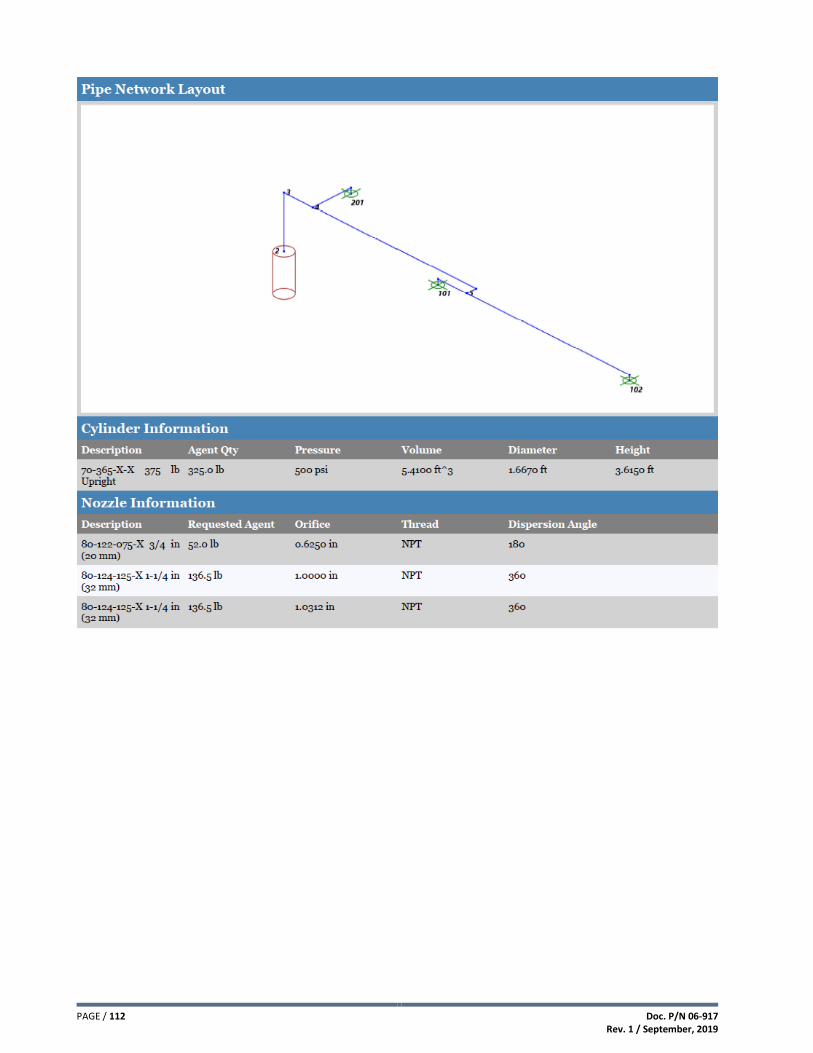
PAGE / 112 Doc. P/N 06-917 Rev. 1 / September, 2019

Doc. P/N 06-917 Rev. 1 / September, 2019
PAGE / 113

PAGE / 114 Doc. P/N 06-917 Rev. 1 / September, 2019
This page intentionally left blank.

Doc. P/N 06-917 Rev. 1 / September, 2019
PAGE / 115
APPENDIX B – Safety Data Sheets
3M™ Novec™ 1230 Fire Protection Fluid
Nitrogen
These data sheets are only controlled while on the manufacturer’s website. The controlled version is available for download from the manufacturer’s website. The manufacturers cannot assure the integrity or accuracy of the SDS information contained in this document after it has been downloaded from their respective websites.
www.3M.com
www.praxair.com

PAGE / 116 Doc. P/N 06-917 Rev. 1 / September, 2019

Doc. P/N 06-917 Rev. 1 / September, 2019
PAGE / 117

PAGE / 118 Doc. P/N 06-917 Rev. 1 / September, 2019

Doc. P/N 06-917 Rev. 1 / September, 2019
PAGE / 119

PAGE / 120 Doc. P/N 06-917 Rev. 1 / September, 2019

Doc. P/N 06-917 Rev. 1 / September, 2019
PAGE / 121

PAGE / 122 Doc. P/N 06-917 Rev. 1 / September, 2019

Doc. P/N 06-917 Rev. 1 / September, 2019
PAGE / 123

PAGE / 124 Doc. P/N 06-917 Rev. 1 / September, 2019

Doc. P/N 06-917 Rev. 1 / September, 2019
PAGE / 125

PAGE / 126 Doc. P/N 06-917 Rev. 1 / September, 2019

Doc. P/N 06-917 Rev. 1 / September, 2019
PAGE / 127

PAGE / 128 Doc. P/N 06-917 Rev. 1 / September, 2019

Doc. P/N 06-917 Rev. 1 / September, 2019
PAGE / 129

PAGE / 130 Doc. P/N 06-917 Rev. 1 / September, 2019

Doc. P/N 06-917 Rev. 1 / September, 2019
PAGE / 131

PAGE / 132 Doc. P/N 06-917 Rev. 1 / September, 2019

Doc. P/N 06-917 Rev. 1 / September, 2019
PAGE / 133
APPENDIX C – Selector Valve Calculation Example
In the following example, selector valves are being utilized to protect four rooms of equal size requiring 326 lbs. of agent. Individual flow calculations have been run for each hazard and 1 ¼” schedule 40 pipe has been selected for the piping leading up to the selector valves.
To determine the maximum total length of 1 ¼” pipe allowed to entrap agent during discharge, multiply the agent quantity (i.e., 326 lbs.) by the multiplier taken from the table on Page 55 for 1 ¼” schedule 40 pipe.
326 lbs. x 0.096420 = 31.43 feet allowed
Evaluate the piping network to determine which selector valve (if activated) would cause the greatest amount of agent
to become entrapped in the pipe network. This is done by totaling the length of each pipe section where the agent will
be entrapped with no flow. If in doubt as to which selector valve presents the worst case scenario, evaluate each selector
valve individually.
Agent Flow to Hazard “A”
(24 inches x 6 = 12 feet of 1 ¼” pipe)
Agent Flow to Hazard “B”
(24 inches x 5 = 10 feet of 1 ¼” pipe)
NOTE: Shaded pipe indicates areas of agent entrapment.

PAGE / 134 Doc. P/N 06-917 Rev. 1 / September, 2019
Agent Flow to Hazard “C”
(24 inches x 4 = 8 feet of 1 ¼” pipe)
Agent Flow to Hazard “D”
(24 inches x 3 = 6 feet of 1 ¼” pipe)
NOTE: Shaded pipe indicates areas of agent entrapment.
Compare the allowable pipe length against the designed pipe network that serves the selector valves.
Hazard “A” = 12 feet of pipe allowing agent entrapment
Hazard “B” = 10 feet of pipe allowing agent entrapment
Hazard “C” = 8 feet of pipe allowing agent entrapment
Hazard “D” = 6 feet of pipe allowing agent entrapment
As long as the quantity of pipe that allows the entrapment of agent does not exceed the allowable pipe length of 31.43 feet, the piping network serving the selector valve is acceptable. If exceeded, the piping network must be modified.

REVISION HISTORY ORIGINAL RELEASE DATE: .......................................................................................................................................... June, 2019
REVISION / DESCRIPTION OF CHANGE REVISION DATE
Revision 1 .................................................................................................................................................. September, 2019 1) Revised container weights and heights in Sections 2.2, 3.11 and 4.1. 2) Updated IVO Kit 70-279 in Sections 2.8 and 2.11 (removed plastic cap and cotter pin). 3) Increased ceiling height maximum from 13.45 ft to 16.00 ft in Sections 3.15.1 and 3.15.2. 4) Added FM note in Section 2.18.

This page intentionally left blank.


CONTACT US Fike World Headquarters
704 SW 10th Street
Blue Springs, Missouri 64015 USA
Tel: +001 816-229-3405
Toll Free (US Only): 1-800-YES-FIKE (1-800-937-3453)
www.Fike.com
For a list of contact information for Fike offices around
the world, visit the Global Locations section of Fike.com