Embed Size (px)
Citation preview

ARCH 331 Note Set 4.1 S2012abn
1
X
X
Equilibrium of a Particle & Truss Analysis
Notation:
b = number of members in a truss
(C) = shorthand for compression
F = name for force vectors, as is X, and
P
FAB = name of a truss force between joints
named A and B, ex.
FBD = free body diagram
Fx = force component in the x direction,
as is Tx
Fy = force component in the y direction,
as is Ty
h = cable sag height
L = span length
n = number of joints in a truss
N = normal force (perpendicular to
something)
R = name for resultant vectors
Rx = resultant component in the x
direction
Ry = resultant component in the y
direction
T = name for a tension force
(T) = shorthand for tension
x = x axis direction, or horizontal
dimension
y = y axis direction, or vertical
dimension
W = name for force due to weight
= coefficient of static friction
= angle, in a trig equation, ex. sin ,
that is measured between the x axis
and tail of a vector
= summation symbol
EQUILIBRIUM is the state where the resultant of the forces on a particle or a rigid body is
zero. There will be no rotation or translation. The forces are referred to as balanced.
ex: 2 forces of same size, opposite direction
ex: 4 forces, polygon rule shows that it closes
Analytically, for a point:
0 xx FR 0 yy FR (scalar addition)
NEWTON’S FIRST LAW: If the resultant force acting on a particle is zero, the particle will
remain at rest (if originally at rest) or will move with constant speed in a straight line (if
originally in motion).
ARCH 331 Note Set 4.1 S2012abn
2
Collinear Force System
All forces act along the same line. Only one equilibrium equation is needed: 0)( lineinF
Equivalently: xx FR 0 and yy FR 0
Concurrent Force System
All forces act through the same point. Only two equilibrium equations are needed:
xx FR 0 and yy FR 0
It is ABSOLUTELY NECESSARY to consider all the forces acting on a body (applied
directly and indirectly) using a FREE BODY DIAGRAM. Omission of a force would ruin
the conditions for equilibrium.
FREE BODY DIAGRAM (aka FBD): Sketch of a significant isolated particle of a body or
structure showing all the forces acting on it. Forces can be from
externally applied forces
weight of the rigid body
reaction forces or constraints
forces developed within a section member
How to solve when there are more than three forces on a free body:
1. Resolve all forces into x and y components using known and unknown forces and
angles. (Tables are helpful.)
2. Determine if any unknown forces are related to other forces and write an equation.
3. Write the two equilibrium equations (in x and y).
4. Solve the equations simultaneously when there are the same number of equations
as unknown quantities. (see math handout)
Common problems have unknowns of: 1) magnitude of force
2) direction of force
FREE BODY DIAGRAM STEPS FOR A POINT;
1. Determine the point of interest. (What point is in equilibrium?)
2. Detach the point from and all other bodies (“free” it).

ARCH 331 Note Set 4.1 S2012abn
3
3. Indicate all external forces which include:
- action on the point by the supports & connections
- action on the point by other bodies
- the weigh effect (=force) of any body attached to the point (force due to gravity)
4. All forces should be clearly marked with magnitudes and direction. The sense of forces
should be those acting on the point not from the point.
5. Dimensions/angles should be included for force component computations.
6. Indicate the unknown forces, such as those reactions or constraining forces where the body is
supported or connected.
Force Reactions can be categorized by the type of connections or supports. A force reaction
is a force with known line of action, or a force of unknown direction. The line of action of
the force is directly related to the motion that is prevented.
The line of action should be indicated on the FBD. The sense of direction is determined by
the type of support. (Cables are in tension, etc…) If the sense isn’t obvious, assume a sense.
When the reaction value comes out positive, the assumption was correct. When the reaction
value comes out negative, the assumption was opposite the actual sense. DON’T CHANGE
THE ARROWS ON YOUR FBD OR SIGNS IN YOUR EQUATIONS.
With the 2 equations of equilibrium for a point, there can be no more than 2 unknowns.
Friction
There will be a force of resistance to movement developed at the contact face between
objects when one is made to slide against the other. This is known as static friction and is
determined from the reactive force, N, which is normal to the surface, and a coefficient of
friction, , which is based on the materials in contact.
NμF
prevents motion:
up and down
prevents motion:
vertical & horizontal

ARCH 331 Note Set 4.1 S2012abn
4
If the static friction force is exceeded by the pushing force, there
will still be friction, but it is called kinetic friction, and it is smaller
than static friction, so it is moving.
The friction resistance is independent of the amount of contact area.
Materials range
Metal on ice 0.03-0.05
Metal on metal 0.15-0.60
Metal on wood 0.20-0.60
Metal on stone 0.30-0.70
Wood on wood 0.30-0.70
Steel on steel 0.75
Stone on stone 0.40-0.70
Rubber on concrete 0.60-0.90
Aluminum on aluminum 1.10-1.70
CABLE STRUCTURES:
Cables have the same tension all along the length if they are not cut. The force magnitude is
the same everywhere in the cable even if it changes angles. Cables CANNOT be in
compression. (They flex instead.)
High-strength steel is the most common material used for cable structures because it has a
high strength to weight ratio.
Cables must be supported by vertical supports or towers and must be anchored at the ends.
Flexing or unwanted movement should be resisted. (Remember the Tacoma Narrows
Bridge?)
Cables with a single load have a concurrent force
system. It will only be in equilibrium if the cable is
symmetric.
The forces anywhere in a straight segment can be
resolved into x and y components of cosTTx and
sinTTy .

ARCH 331 Note Set 4.1 S2012abn
5
B
6 m A
C
45 kN
4 m
2 m
45 kN
Tx Tx
The shape of a cable having a uniform distributed load is almost parabolic, which means the
geometry and cable length can be found with:
224 L/)xLx(hy
where y is the vertical distance from the straight
line from cable start to end
h is the vertical sag (maximum y)
x is the distance from one end to the location of y
L is the horizontal span.
)L
hL
h(LLtotal 4
4
532
2
2
381
where Ltotal is the total length of parabolic cable
h and L are defined above.
Cables with Several Concentrated Loads or Fixed Geometry
In order to completely constrain cables, the number of unknown support reactions will be
more than the available number of equilibrium equations. We can solve because we have
additional equations from geometry due to the slope of the cable.
The tension in the cable IS NOT the same everywhere, but the horizontal component in a
cable segment WILL BE.
h y
x L

ARCH 331 Note Set 4.1 S2012abn
6
Truss Structures
A truss is made up of straight two-force members connected at its ends. The triangular
arrangement produces stable geometry. Loads on a truss are applied at the joints only.
Joints are pin-type connections (resist translation, not rotation).
Forces of action and reaction on a joint must be equal and opposite.
Members in TENSION are being pulled.
Members in COMPRESSION are being squeezed.
External forces act on the joints.
Truss configuration:
Three members form a rigid assembly with 3 (three) connections.
To add members and still have a rigid assembly, 2 (two) more must be added with one
connection between.
For rigidity: b = 2n – 3, where b is number of members and n is number of joints
Method of Joints
The method takes advantage of the conditions of equilibrium at each joint.
1. Determine support reaction forces.
2. Draw a FBD of each member AND each joint
3. Identify geometry of angled members
4. Identify zero force members and other special (easy to solve) cases
5. Each pin is in equilibrium ( 0 xF and 0 yF for a concurrent force system)
6. Total equations = 2n = b+3 (one force per member + 3 support reactions)
Advantages: Can find every member force
Disadvantages: Lots of equations, easy to lose track of forces found.
Tools available:

ARCH 331 Note Set 4.1 S2012abn
7
A B
C
P
F
E
D
P
A B
C
A B
C or
(0)
(0)
A
B
C
A B
C
or or even
C B
A D
D D
(0) (0) (0)
Tip-to-tail method for 3 joint forces must close
Analytically, there will be at most 2 unknowns with 2 equilibrium equations.
Joint Configurations (special cases to recognize for faster solutions)
Case 1) Two Bodies Connected
FAB has to be equal (=) to FBC
Case 2) Three Bodies Connected with Two Bodies in Line
FAB and FBC have to be equal, and FBD has to be 0 (zero).

ARCH 331 Note Set 4.1 S2012abn
8
A B
C
C
B
A
P
D
D
P
C
B
A
D
E
C B
A
D
E
P
P
Case 3) Three Bodies Connected and a Force – 2 Bodies aligned & 1 Body and a Force are
Aligned
Four Bodies Connected - 2 Bodies Aligned and the Other 2 Bodies Aligned
FAB has to equal FBC, and [FBD has to equal P] or [FBD has to equal FBE]
Graphical Analysis
The method utilizes what we know about force triangles and plotting force magnitudes to scale.
1. Draw an accurate form diagram of the truss at a convenient scale with the loads and support
reaction forces.
2. Determine the support reaction forces.
3. Working clockwise and from left to right, apply interval notation to the diagram, assigning
capital letters to the spaces between external forces and numbers to internal spaces.
4. Construct a load line to a convenient scale of length to force by using the interval notation
and working clockwise around the truss from the upper left plotting the lengths of the vertical
and horizontal loads.
5. Starting at a left joint where we know there are fewer than three forces, we draw reference
lines in the direction of the unknown members so that they intersect. Label the intersection
with the number of the internal space.
6. Go to the next joint (clockwise and left to right) with two unknown forces and repeat for all
joints. The diagram should close.
7. Measure the line segments and apply interval notation to determine their sense: Proceeding
clockwise around the joint, follow the notation. The direction toward the joint is
compressive. The direction away from the joint is tensile.

ARCH 331 Note Set 4.1 S2012abn
9
Example 1 (pg 49)
ARCH 331 Note Set 4.1 S2012abn
10
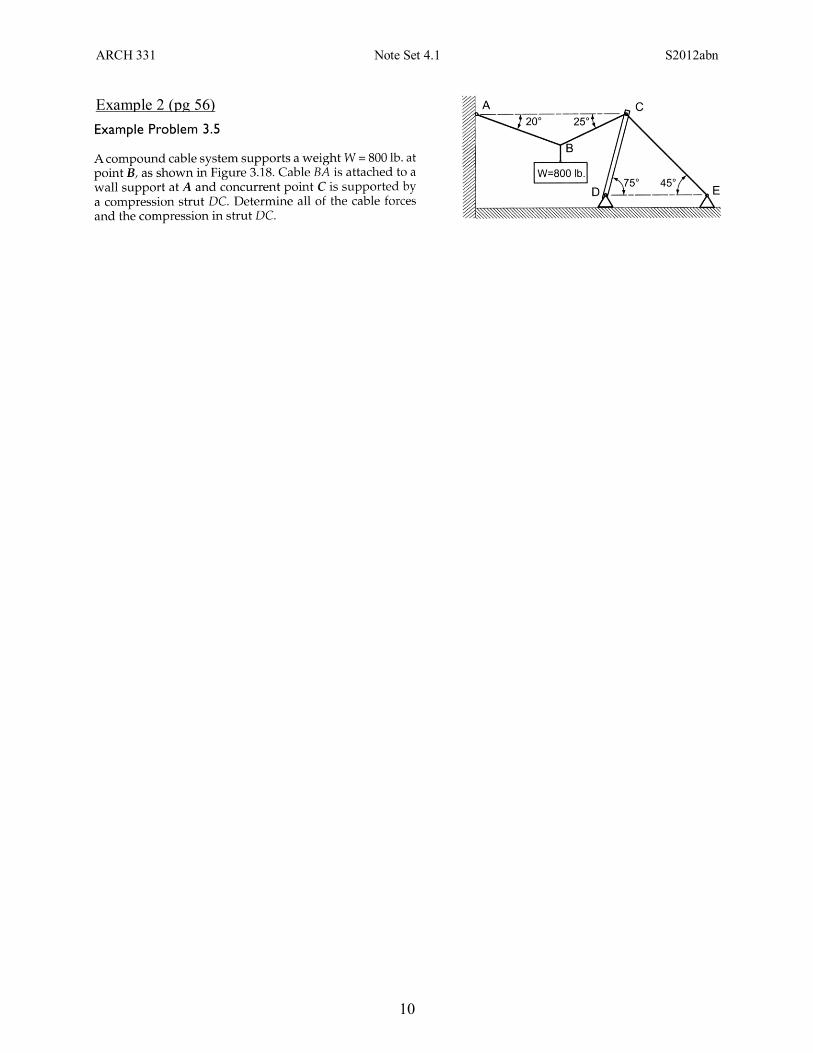
Example 2 (pg 56)

ARCH 331 Note Set 4.1 S2012abn
11
Example 3 (pg 90)
U
1800 lb. 2400 lb.
1200
.

ARCH 331 Note Set 4.1 S2012abn
12
Example 4 Using the method of joint, determine all member forces.
SOLUTION: Find the joints with 2 (or less unknowns) for FBD’s : A and H, while looking for any special cases like E, which has “crossed” members and forces. FDE = FEF and FEC = 500 lb (tension). (Check off members found: AB, BD, AD, BC, DC, DE, EC, EF, CG, CF, FG, GH, FH) Let’s use A first (but H is just as acceptable). Draw the point, adding the known force, and draw the unknown member forces away from the point, assuming tension (shown as dashed). Find the geometry of member AB from the rise of 10 ft and the run of 15 ft. The hypotenuse will be
22 1510 = 18.03:
00318
15
.FFF ABADx
00318
105412
.F.F AB
lb
y FAB =(-412.5)*18.03/10 = -743.7 lb (C)
and substituting the (negative) value of FAB into the xF , FAD = 618.75 lb (T)
(Check off members found: AB, BD, AD, BC, DC, DE, EC, EF, CG, CF, FG, GH, FH) Review which joints have 2 (or less) unknowns: B and H. Let’s use B. Because we know FAB is in compression we draw the force into the point. We need the geometry of member BC with a rise of 5 (15-10) and a run of 15 with a
hypotenuse of 22 155 = 15.81:
081.15
15
03.18
157.743 BC
lb
x FF FBC = -652.1 lb (C)
081.15
5
03.18
107.743 BDBC
lb
y FFF (substituting the negative value of FBC)
FBD = 206.2 lb (T) (Check off members found: AB, BD, AD, BC, DC, DE, EC, EF, CG, CF, EF, FG, GH, FH) Review which joints have 2 (or less) unknowns: D and H. Let’s use D. Both FAD and FBD are tensile, so we can draw them away. The geometry of DE is familiar with the rise the same as the run for an angle of 45°:
04575618 DEDC
lb
x FcosF.F
045sin2.206150 DC
lblb
y FF FDC = -79.5 lb (C)
and substituting the (negative) value of FDC into the xF , FDE = 675.0 lb (T) = FEF (! from above)
(Check off members found: AB, BD, AD, BC, DC, DE, EC, EF, CG, CF, FG, GH, FH) Review which joints have 2 (or less) unknowns: C and H. Let’s use C. Draw FDC and FBC as compressive forces. And the geometry has been found due to symmetry, with the angle of FCF a negative 45°:
081.15
15)45cos(45cos5.79
81.15
151.652 CGCF
lblb
x FFF
081.15
5)45sin(50045sin5.79
81.15
51.652 CGCF
lblblb
y FFF
Solve simultaneously because there isn’t an easy way to find one unknown equal to a value multiplied by the other unknown:
0949.0707.09.674 CGCF
lb
x FFF
0316.0707.06.237 CGCF
lb
y FFF
add: 0633.005.437 CGCF
lb FF FCG = -690.8 lb (C) and substituting, FCF = -27.6 lb (C)
(Check off members found: AB, BD, AD, BC, DC, DE, EC, EF, CG, CF, FG, GH, FH)
150 LBS 200 LBS 500 LBS 437.5 LBS 412.5 LBS
412.5 LBS
FAB
FAD
15
5 15.81
500 LBS
FEF FDE
FEC
FBC
FBD 743.7 LBS
15
10 18.03
15
10 18.03
150 LBS FDE 618.75 LBS
206.2 LBS FDC
45°
FCG
FCF
15
5 15.81
45°
500 LBS 79.5 LBS
652.1 LBS
15
5 15.81
ARCH 331 Note Set 4.1 S2012abn
13
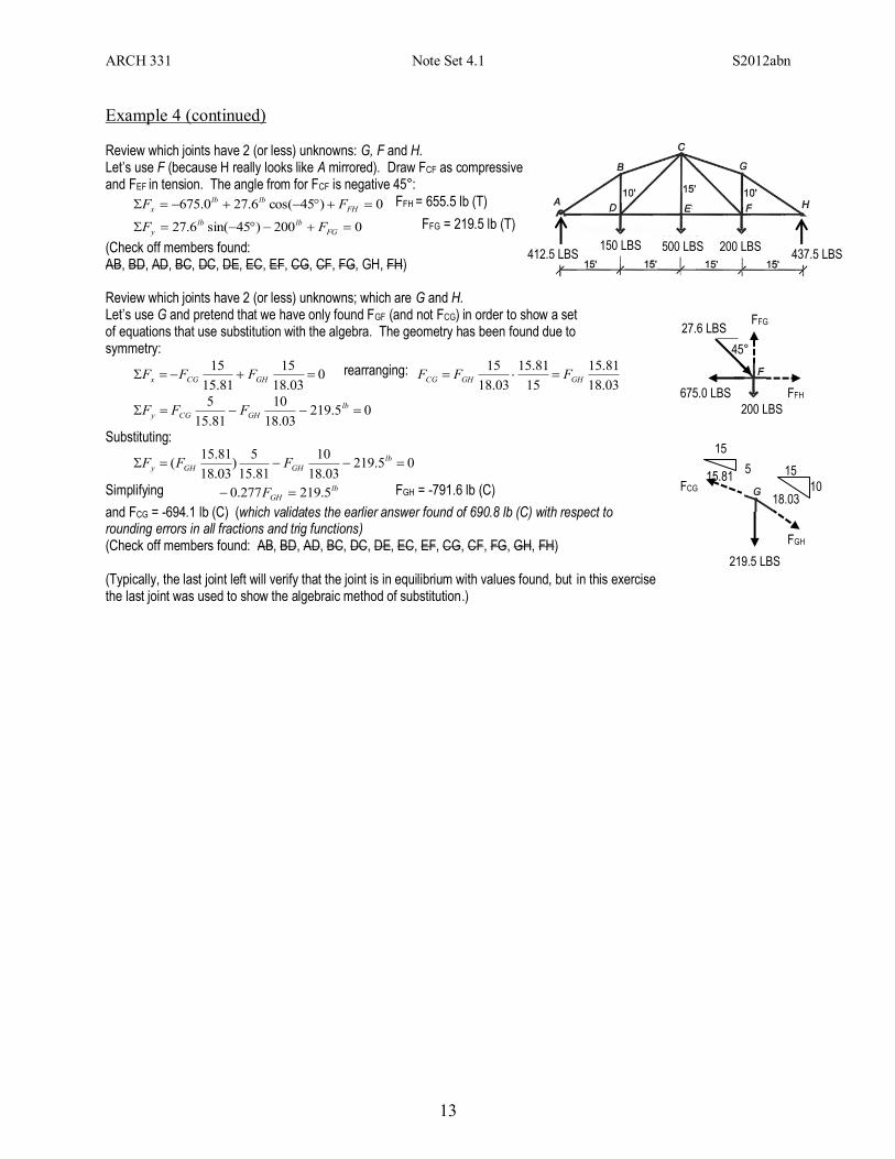
Example 4 (continued) Review which joints have 2 (or less) unknowns: G, F and H. Let’s use F (because H really looks like A mirrored). Draw FCF as compressive and FEF in tension. The angle from for FCF is negative 45°:
0)45cos(6.270.675 FH
lblb
x FF FFH = 655.5 lb (T)
0200)45sin(6.27 FG
lblb
y FF FFG = 219.5 lb (T)
(Check off members found: AB, BD, AD, BC, DC, DE, EC, EF, CG, CF, FG, GH, FH) Review which joints have 2 (or less) unknowns; which are G and H. Let’s use G and pretend that we have only found FGF (and not FCG) in order to show a set of equations that use substitution with the algebra. The geometry has been found due to symmetry:
003.18
15
81.15
15 GHCGx FFF rearranging:
03.18
81.15
15
81.15
03.18
15GHGHCG FFF
05.21903.18
10
81.15
5 lb
GHCGy FFF
Substituting:
05.219
03.18
10
81.15
5)
03.18
81.15( lb
GHGHy FFF
Simplifying lb
GHF 5.219277.0 FGH = -791.6 lb (C)
and FCG = -694.1 lb (C) (which validates the earlier answer found of 690.8 lb (C) with respect to rounding errors in all fractions and trig functions) (Check off members found: AB, BD, AD, BC, DC, DE, EC, EF, CG, CF, FG, GH, FH) (Typically, the last joint left will verify that the joint is in equilibrium with values found, but in this exercise the last joint was used to show the algebraic method of substitution.)
150 LBS 200 LBS 500 LBS 437.5 LBS 412.5 LBS
200 LBS
FFH
FFG
219.5 LBS
15 10
18.03
FGH
45°
675.0 LBS
27.6 LBS
FCG
15
5 15.81