Embed Size (px)
DESCRIPTION
earth quakehigh rise construction
Citation preview
High Rise Buildings in Earthquakes
Underlying Physics
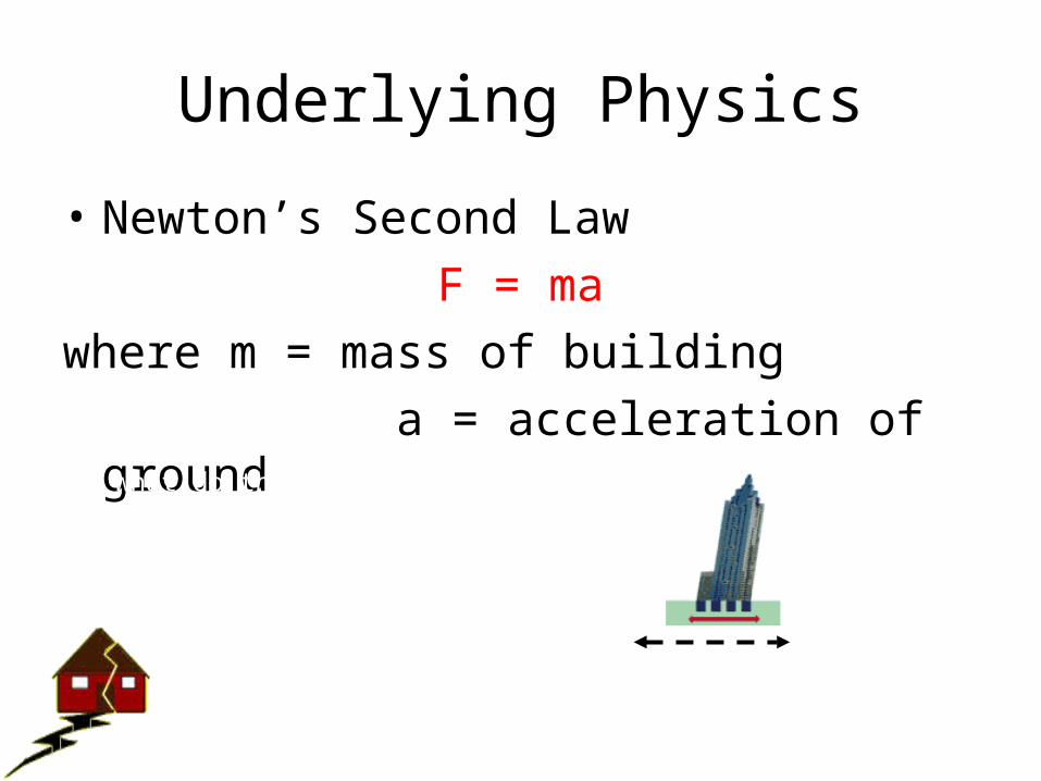
• Newton’s Second LawF = ma
where m = mass of building a = acceleration of ground
ground acceleration
Animation from www.exploratorium.edu/faultline/engineering/engineering5.html
What do the physics tell us about the magnitude of the forces that different types of buildings feel during an earthquake?
What is really happening?
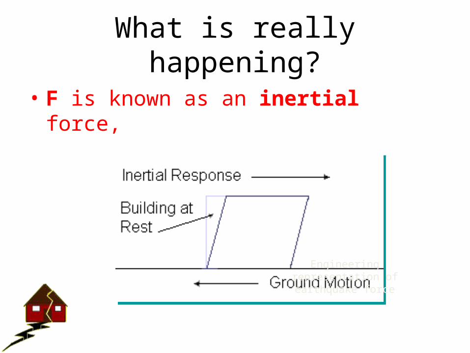
• F is known as an inertial force,
Engineering representation of earthquake force
Period and Frequency
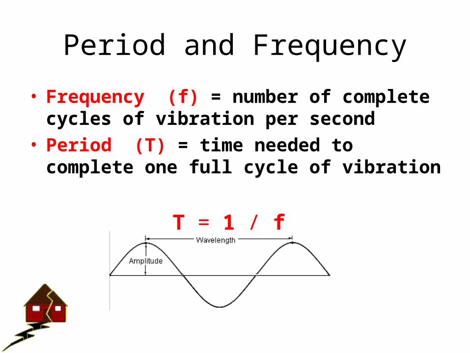
• Frequency (f) = number of complete cycles of vibration per second
• Period (T) = time needed to complete one full cycle of vibration
T = 1 / f
Idealized Model of Building
k
m
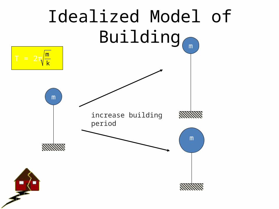
T = 2πk
m
k
m
k
m
smaller k
bigger m
increase building period
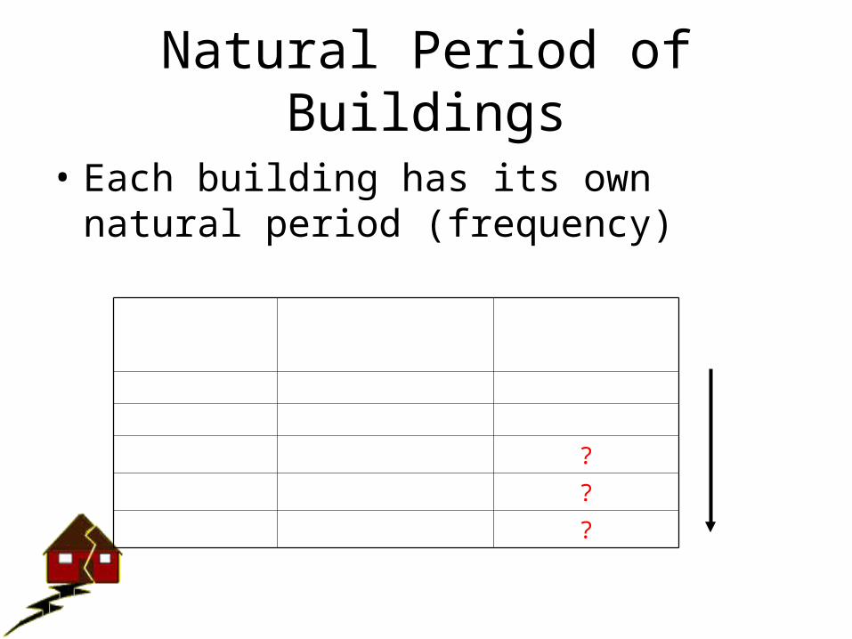
Natural Period of Buildings
• Each building has its own natural period (frequency)
Building Height
Typical Natural Period
Natural Frequency
2 story 0.2 seconds 5 cycles/sec
5 story 0.5 seconds 2 cycles/sec
10 story 1.0 seconds ?
20 story 2.0 seconds ?
30 story 3.0 seconds ?
slower shaking
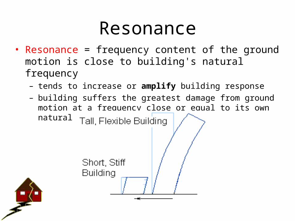
Resonance• Resonance = frequency content of the ground motion is close to
building's natural frequency– tends to increase or amplify building response– building suffers the greatest damage from ground motion at a frequency
close or equal to its own natural frequency
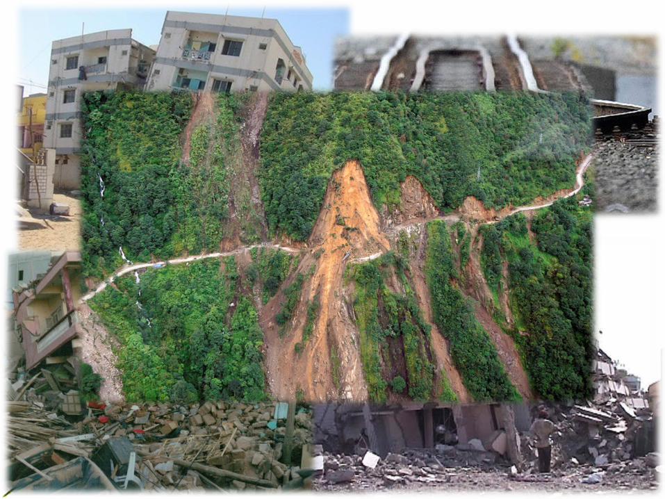
Learn from Earthquake

Soil Failure
• Liquefaction
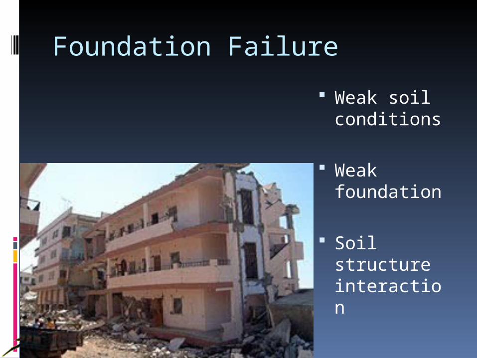
Foundation Failure
Weak soil conditions
Weak foundation
Soil structure interaction
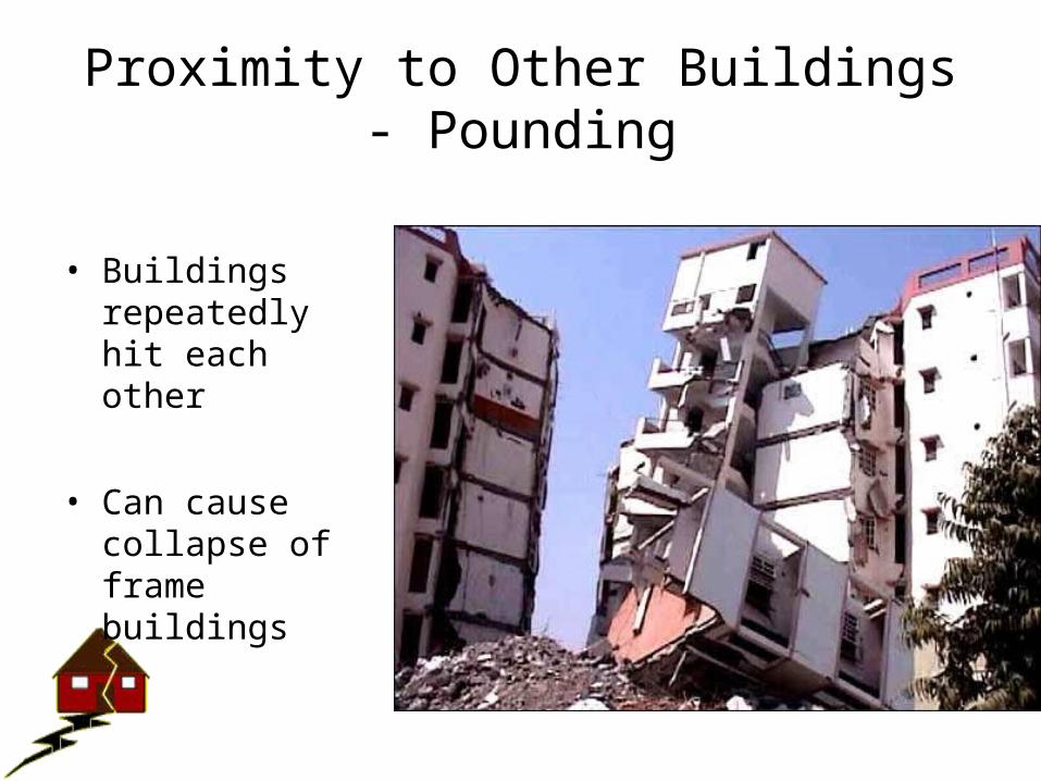
Proximity to Other Buildings - Pounding
• Buildings repeatedly hit each other
• Can cause collapse of frame buildings
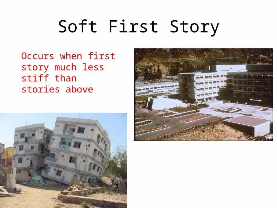
Soft First Story
Occurs when first story much less stiff than stories above
Typical damage – collapse of first story
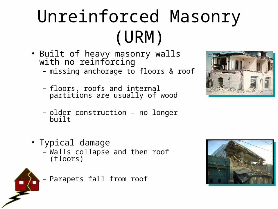
Unreinforced Masonry (URM)• Built of heavy masonry walls with no
reinforcing– missing anchorage to floors & roof
– floors, roofs and internal partitions are usually of wood
– older construction – no longer built
• Typical damage– Walls collapse and then roof (floors)
– Parapets fall from roof
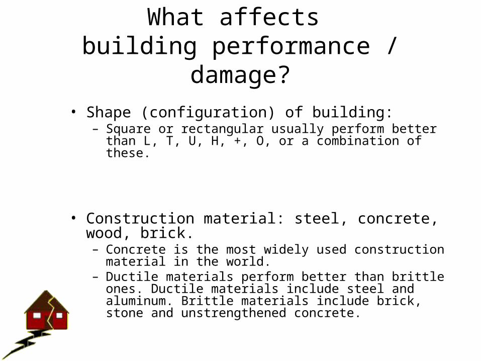
What affects building performance / damage?
• Shape (configuration) of building: – Square or rectangular usually perform better than L, T, U, H, +,
O, or a combination of these.
• Construction material: steel, concrete, wood, brick. – Concrete is the most widely used construction material in the
world. – Ductile materials perform better than brittle ones. Ductile
materials include steel and aluminum. Brittle materials include brick, stone and unstrengthened concrete.
What affects building performance / damage?
• Load resisting system
• Height of the building: (i.e. natural frequency)
• Previous earthquake damage
• Intended function of the building – (e.g. hospital, fire station, office building)
• Proximity to other buildings
• Soil beneath the building
• Magnitude and duration of the earthquake
• Direction and frequency of shaking
Key Factor in Building Performance
Good connections
• Transfer loads from structural elements into foundation and then to ground
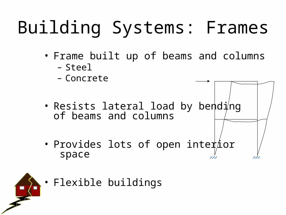
Building Systems: Frames• Frame built up of beams and columns
– Steel– Concrete
• Resists lateral load by bendingof beams and columns
• Provides lots of open interior space
• Flexible buildings
F
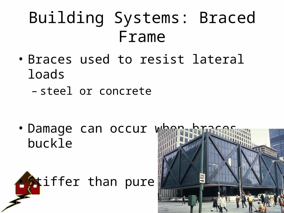
Building Systems: Braced Frame
• Braces used to resist lateral loads– steel or concrete
• Damage can occur when braces buckle
• Stiffer than pure frame
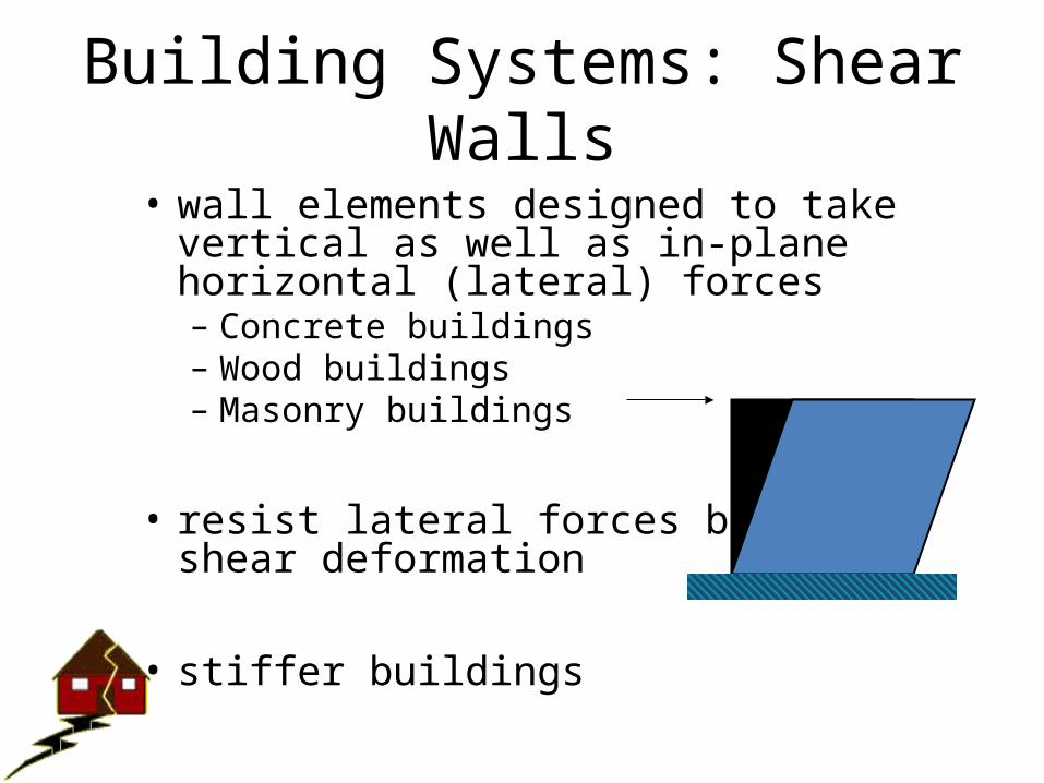
Building Systems: Shear Walls• wall elements designed to take vertical as
well as in-plane horizontal (lateral) forces – Concrete buildings– Wood buildings– Masonry buildings
• resist lateral forces by shear deformation
• stiffer buildings
F
Shear Deformation
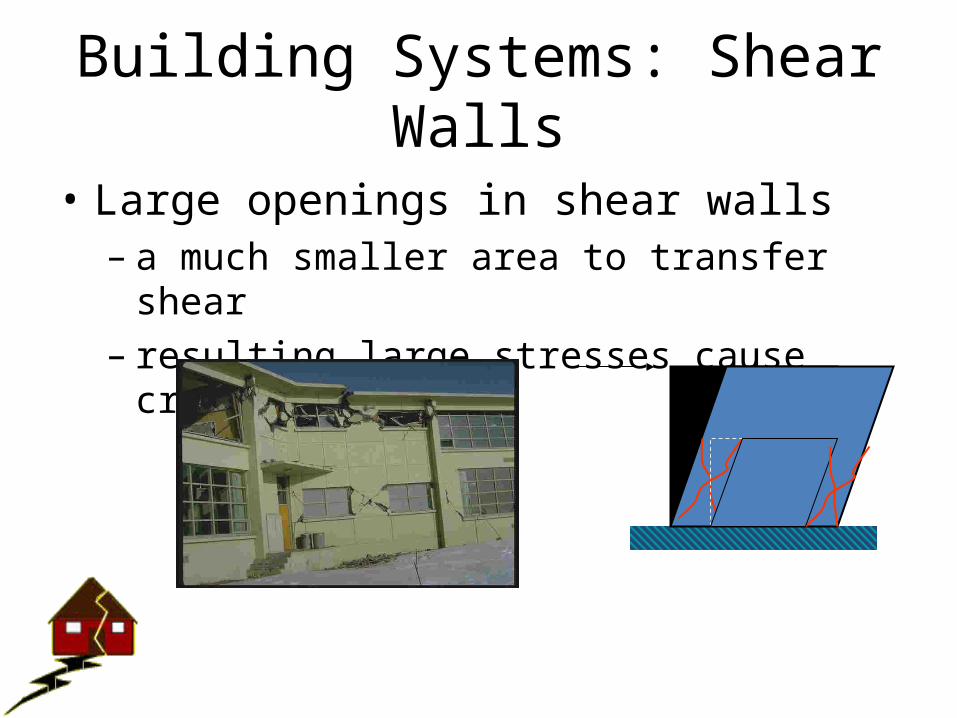
Building Systems: Shear Walls
• Large openings in shear walls – a much smaller area to transfer shear – resulting large stresses cause cracking/failure
F
Cracking around openings
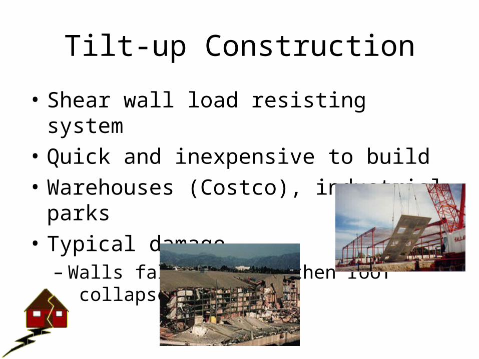
Tilt-up Construction
• Shear wall load resisting system• Quick and inexpensive to build• Warehouses (Costco), industrial parks• Typical damage
– Walls fall outward, then roof collapses
MUSE 11B
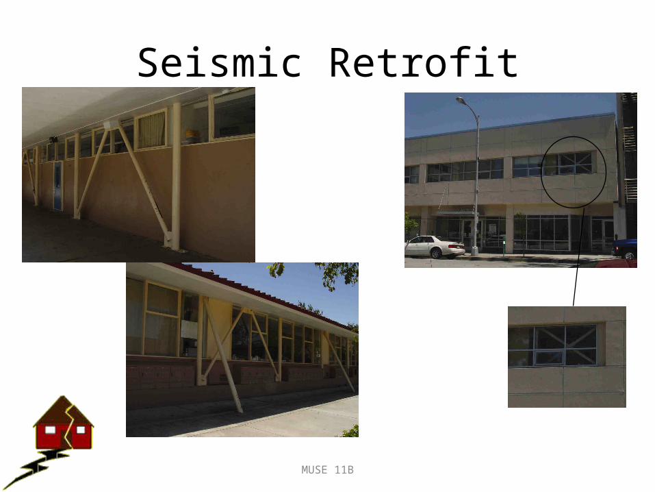
Seismic Retrofit
MUSE 11B
Frames can be used to strengthen older concrete buildings
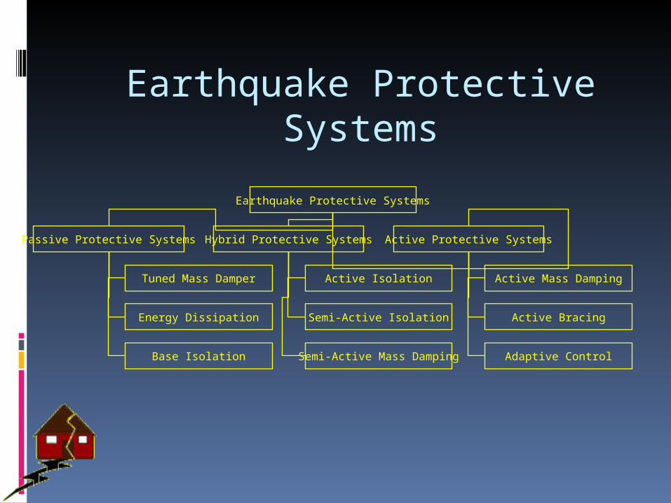
Earthquake Protective Systems
Earthquake Protective Systems
Passive Protective Systems Hybrid Protective Systems Active Protective Systems
Tuned Mass Damper
Energy Dissipation
Base Isolation
Active Isolation
Semi-Active Isolation
Semi-Active Mass Damping
Active Mass Damping
Active Bracing
Adaptive Control
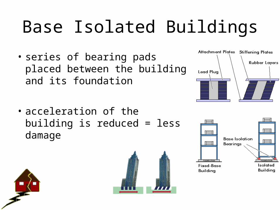
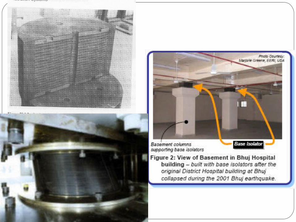
Base Isolated Buildings
• series of bearing pads placed between the building and its foundation
• acceleration of the building is reduced = less damage
isolatednot isolated
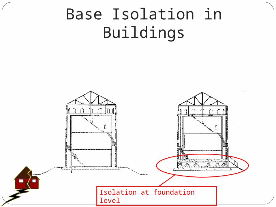
Base Isolation in Buildings
Original Structure Isolated Structure
Isolation at foundation level
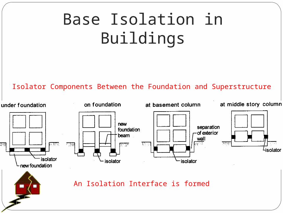
Base Isolation in Buildings
Isolator Components Between the Foundation and Superstructure
An Isolation Interface is formed
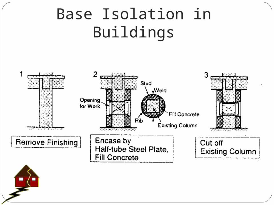
Base Isolation in Buildings
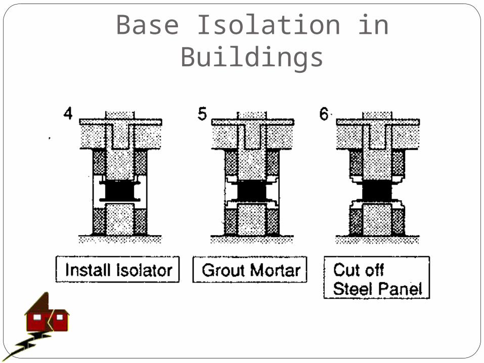
Base Isolation in Buildings
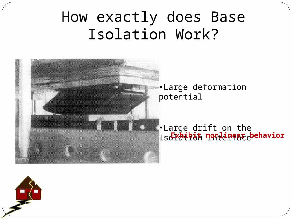
How exactly does Base Isolation Work?
•Large deformation potential
•Large drift on the Isolation Interface
Exhibit nonlinear behavior
Lengthening of the Structure’s Period and increased Damping that result in a large scale decrease of the Seismic Response
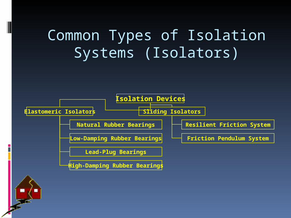
Common Types of Isolation Systems (Isolators)
Isolation Devices
Elastomeric Isolators Sliding Isolators
Natural Rubber Bearings
Low-Damping Rubber Bearings
Lead-Plug Bearings
High-Damping Rubber Bearings
Resilient Friction System
Friction Pendulum System
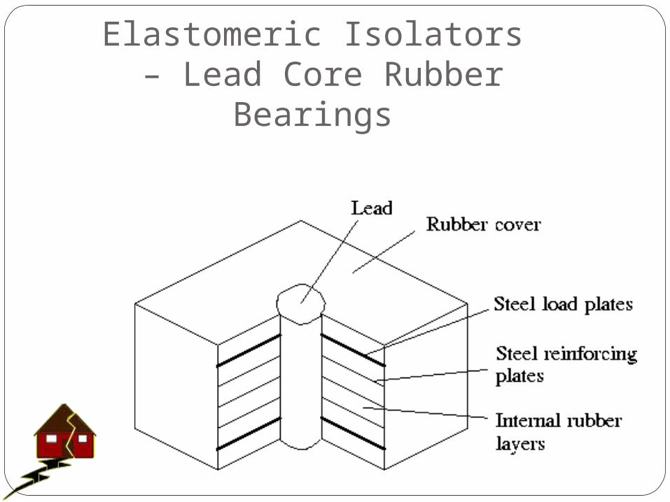
Elastomeric Isolators – Lead Core Rubber Bearings
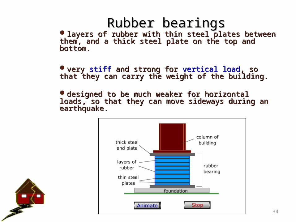
Rubber bearingsRubber bearingslayers of rubber with thin steel plates between them, layers of rubber with thin steel plates between them, and a thick steel plate on the top and bottom. and a thick steel plate on the top and bottom.
very very stiffstiff and strong for and strong for vertical loadvertical load, so that they can , so that they can carry the weight of the building. carry the weight of the building.
designed to be much weaker for horizontal loads, so designed to be much weaker for horizontal loads, so that they can move sideways during an earthquake.that they can move sideways during an earthquake.
34

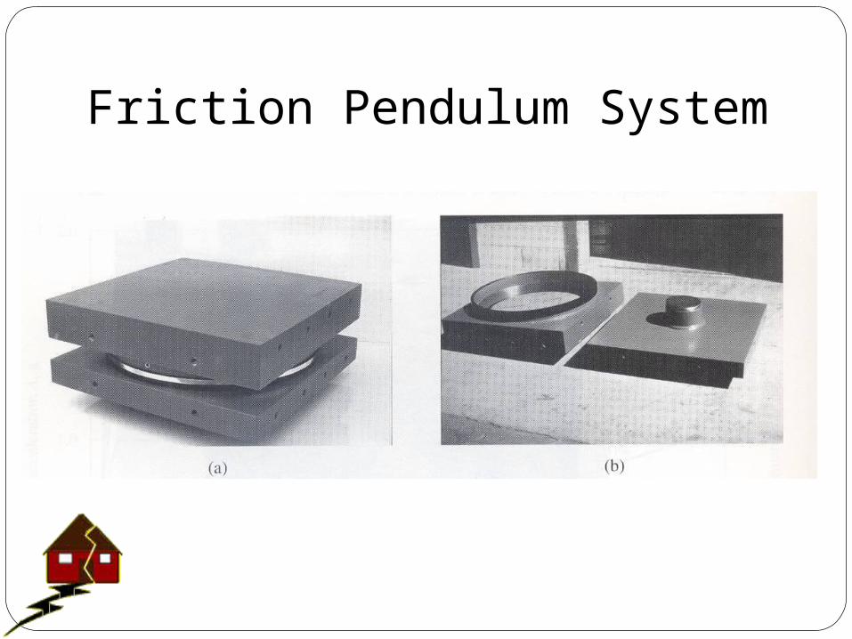
Friction Pendulum BearingsFriction Pendulum Bearings
two horizontal steel plates that can slide over each two horizontal steel plates that can slide over each other because of their shape and an additional other because of their shape and an additional articulated slider. articulated slider.
veryvery stiff and strong for and strong for vertical loadvertical load
36
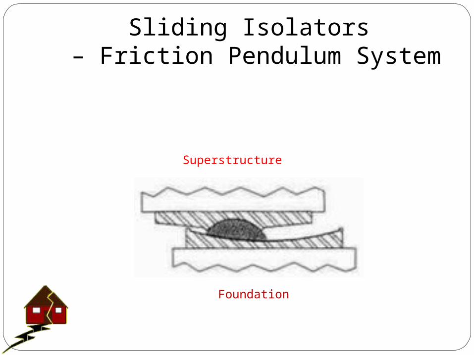
Sliding Isolators – Friction Pendulum System
Superstructure
Foundation
Friction Pendulum System
DampersDampers
Absorb partial energy going into the building Absorb partial energy going into the building from the shaking ground during an from the shaking ground during an earthquake. earthquake.
Reduce the energy available for shaking the Reduce the energy available for shaking the building.building.
building building deformsdeforms less, so the chance of damage is less, so the chance of damage is reduced.reduced.
39
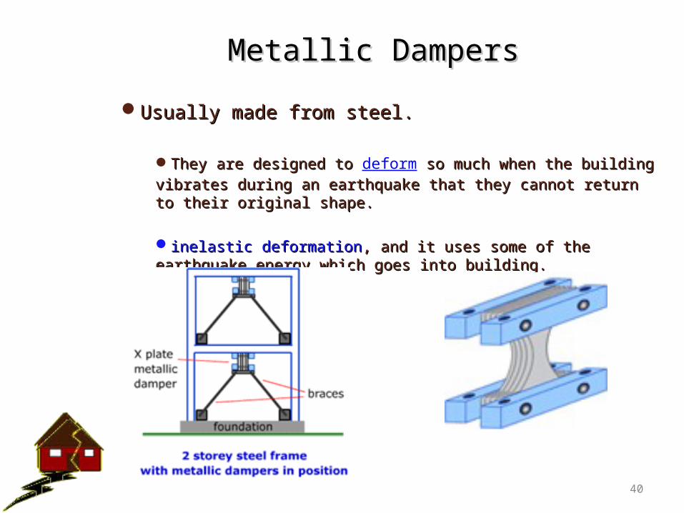
Metallic DampersMetallic Dampers
Usually made from steel. Usually made from steel.
They are designed to They are designed to deform so much when the building so much when the building vibrates during an earthquake that they cannot return to their vibrates during an earthquake that they cannot return to their original shape. original shape.
inelastic deformationinelastic deformation, and it uses some of the earthquake , and it uses some of the earthquake energy which goes into building. energy which goes into building.
40
X - Plate Metallic Damper
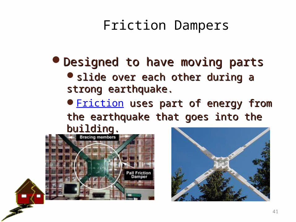
Friction Dampers
Designed to have moving parts Designed to have moving parts slide over each other during a strong slide over each other during a strong earthquake. earthquake. Friction uses part of energy from the uses part of energy from the earthquake that goes into the building. earthquake that goes into the building.
41
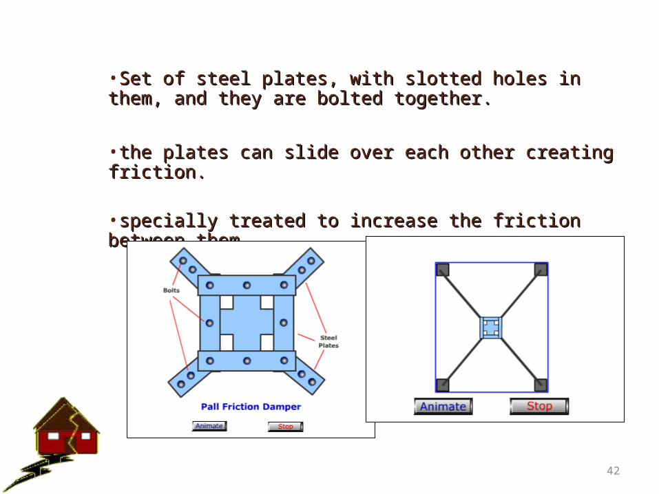
•Set of steel plates, with slotted holes in them, and they Set of steel plates, with slotted holes in them, and they are bolted together.are bolted together.
•the plates can slide over each other creating friction. the plates can slide over each other creating friction.
•specially treated to increase the friction between them.specially treated to increase the friction between them.
42
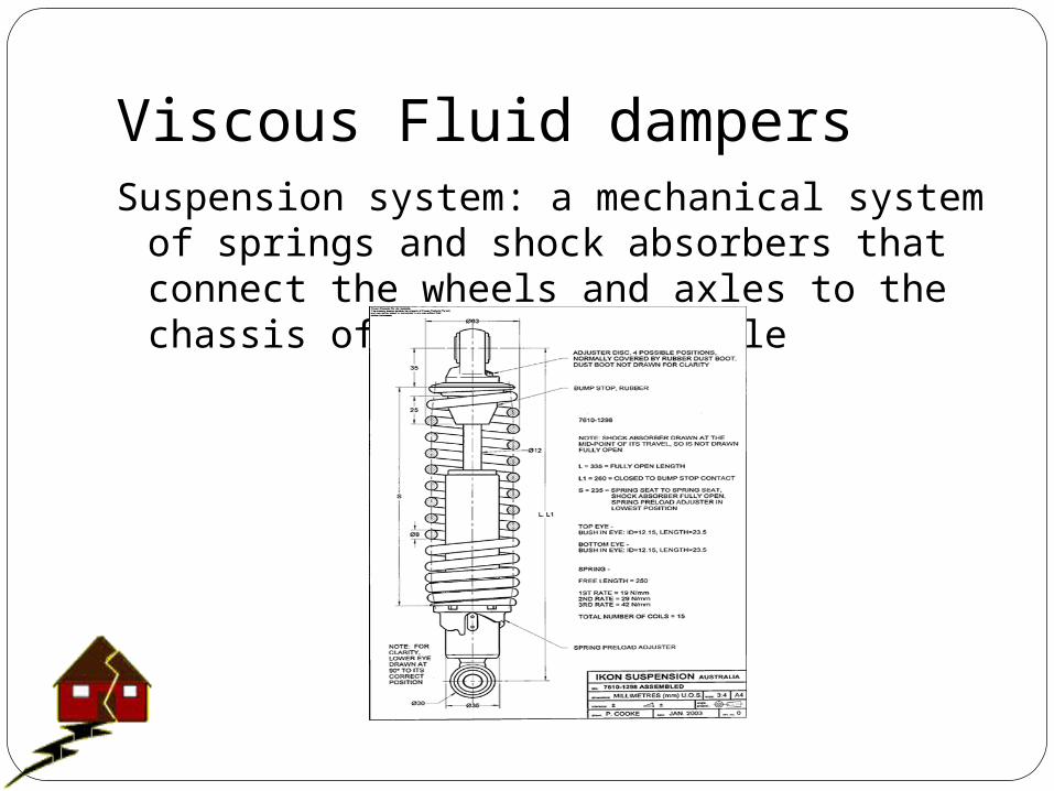
Viscous Fluid dampersSuspension system: a mechanical system of
springs and shock absorbers that connect the wheels and axles to the chassis of a wheeled vehicle
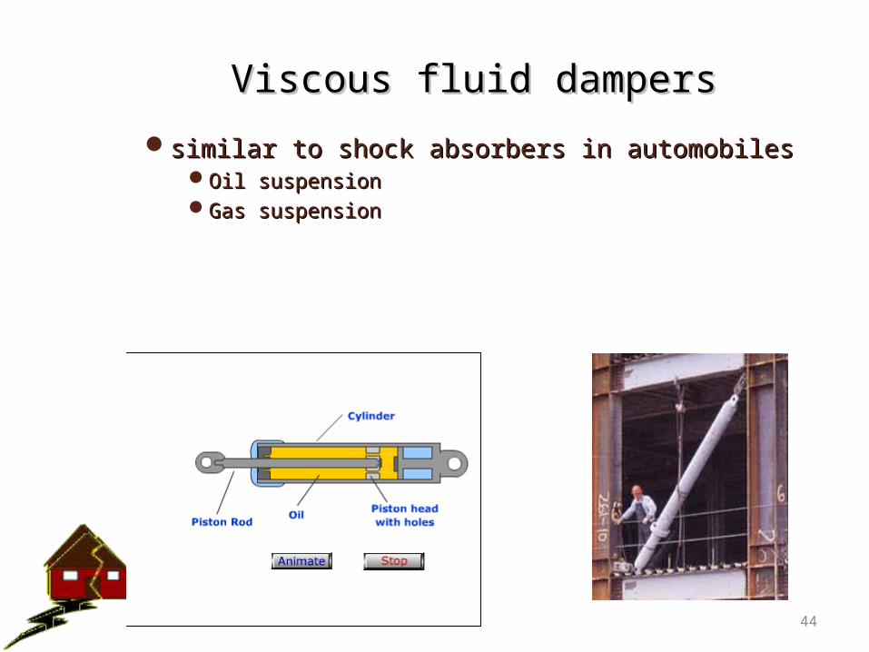
Viscous fluid dampers Viscous fluid dampers
similar to shock absorbers in automobilessimilar to shock absorbers in automobilesOil suspensionOil suspensionGas suspensionGas suspension
44
The Function of suspension system:The job of a car suspension are:
- to carry the static weight of the vehicle - to maximize the friction between the tires
and the road surface, - to provide steering stability with good
handling (minimize body roll)- to ensure the comfort of the passengers
(ability to smooth out a bumpy road).
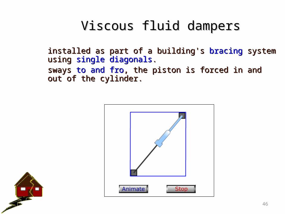
Viscous fluid dampersViscous fluid dampers
installed as part of a building's installed as part of a building's bracingbracing system using system using single diagonalssingle diagonals. . sways sways to and froto and fro, the piston is forced in and out of the , the piston is forced in and out of the cylinder.cylinder.
46
Active Control
• Control system to keep stresses / strains / displ. / accel. (called outputs) at certain locations below specified bounds (peak, rms) when disturbances (wind, earthquake) below specified bound are applied.
• Designer decides choice of – on comfort (accelerations) – safety (stresses).
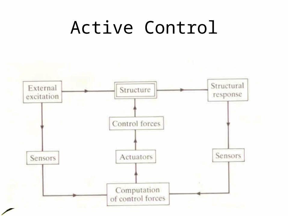
Active Control
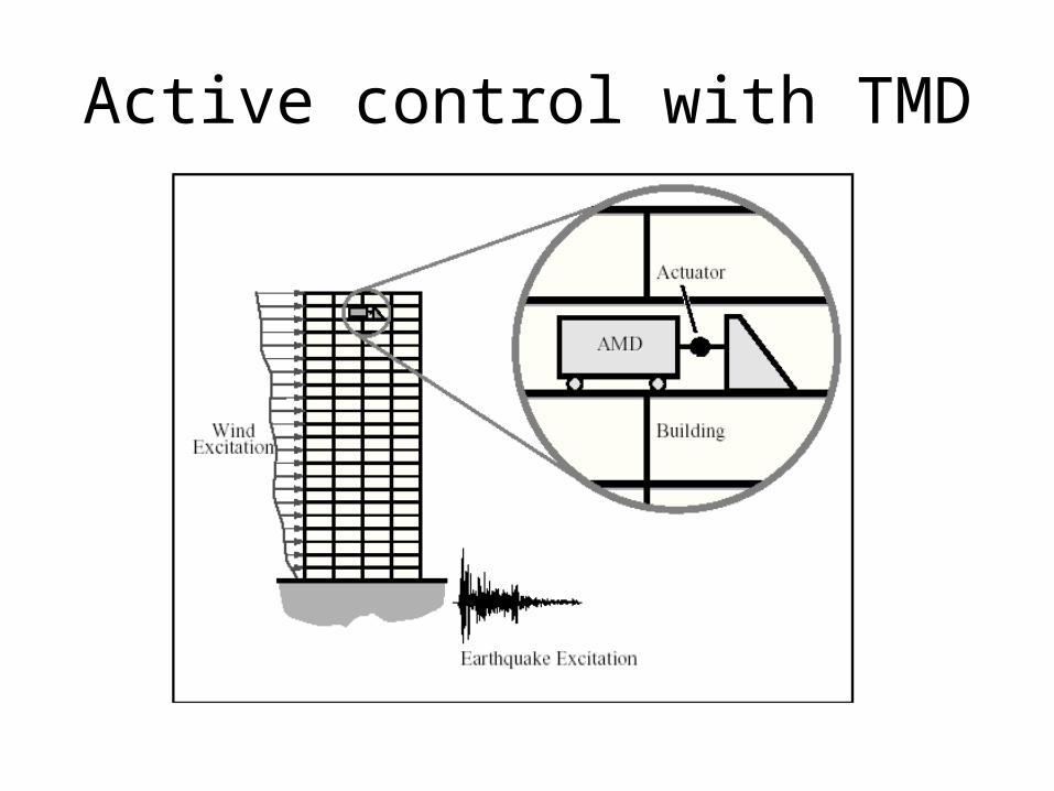
Active control with TMD
Active control with TMD
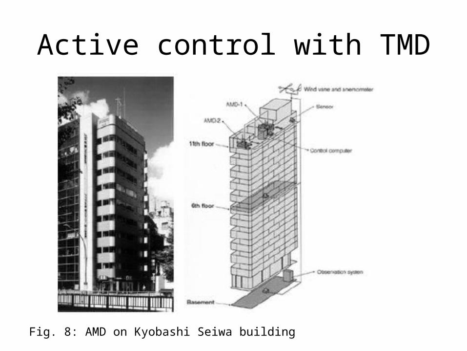
Fig. 8: AMD on Kyobashi Seiwa building
Active control
• First full scale application of active control to a building was done on Kyobashi Seiwa building (Japan) in 1989 (Fig. 7,8). Two AMD’s were used. Primary one weighs 4t and damps transverse motion. Secondary one weighs 1t and damps torsional motion.
• Can also use Magnetorheological fluid dampers (semi-active), active tendons, etc. (Fig. 9, 10, 11)
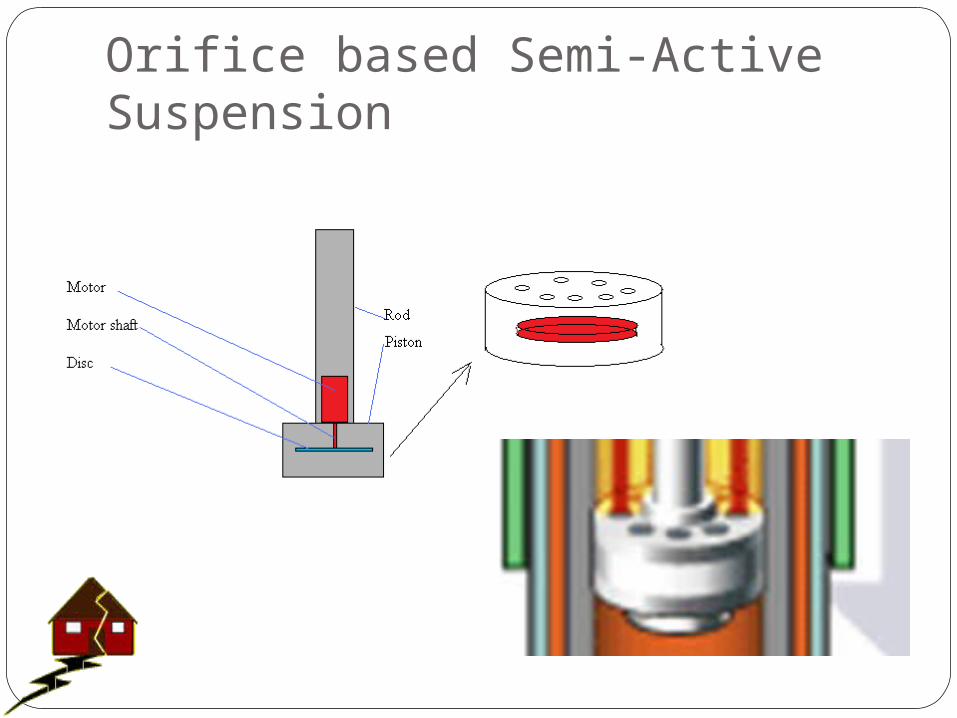
Orifice based Semi-Active Suspension
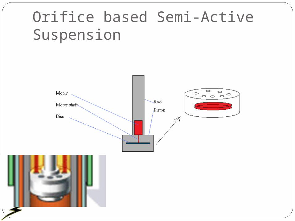
Orifice based Semi-Active Suspension
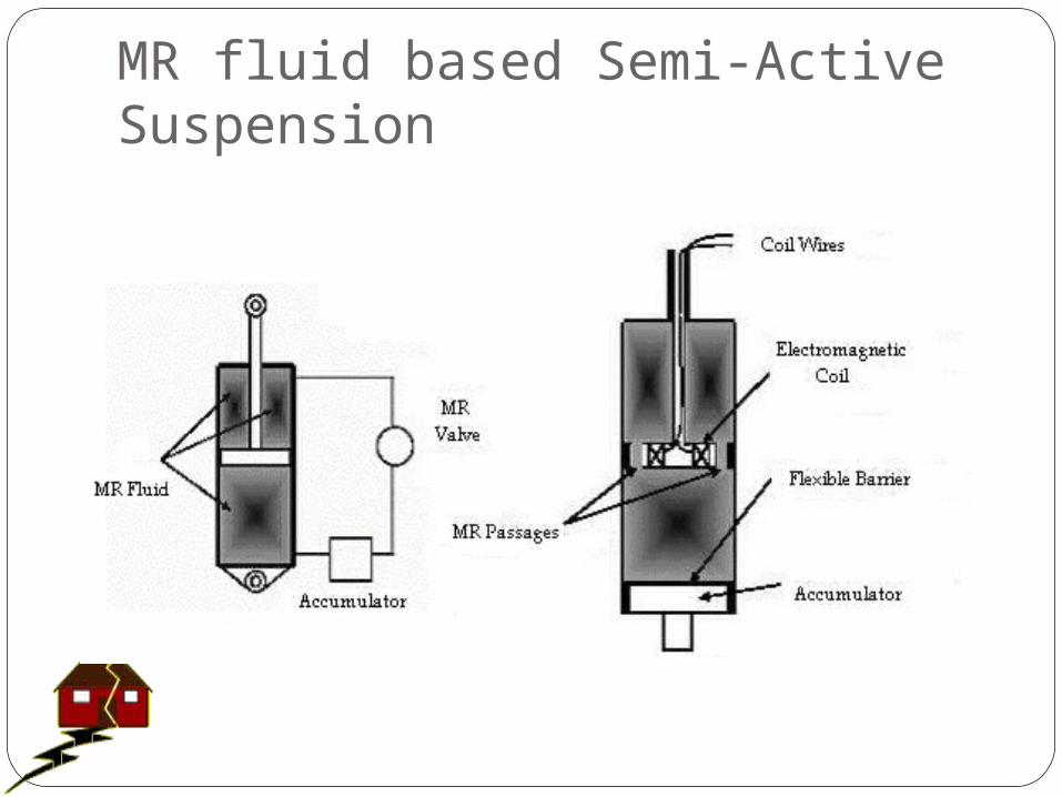
MR fluid based Semi-Active Suspension
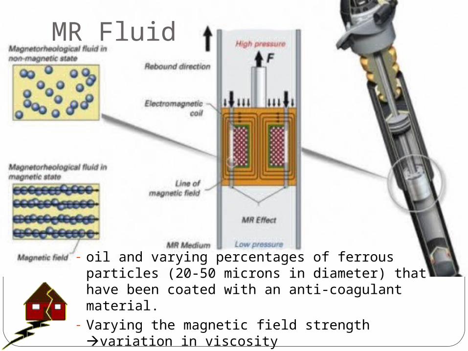
MR Fluid
- oil and varying percentages of ferrous particles (20-50 microns in diameter) that have been coated with an anti-coagulant material.
- Varying the magnetic field strength variation in viscosity
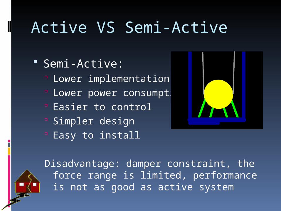
Active VS Semi-Active
Semi-Active: Lower implementation cost Lower power consumption Easier to control Simpler design Easy to install
Disadvantage: damper constraint, the force range is limited, performance is not as good as active system
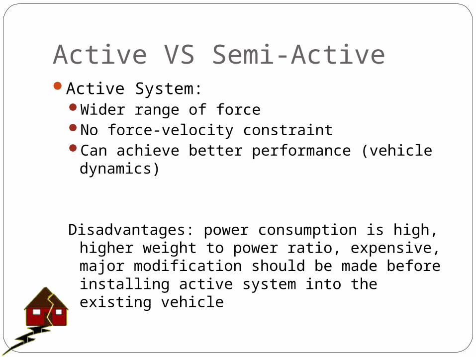
Active VS Semi-ActiveActive System:
Wider range of forceNo force-velocity constraintCan achieve better performance (vehicle
dynamics)
Disadvantages: power consumption is high, higher weight to power ratio, expensive, major modification should be made before installing active system into the existing vehicle
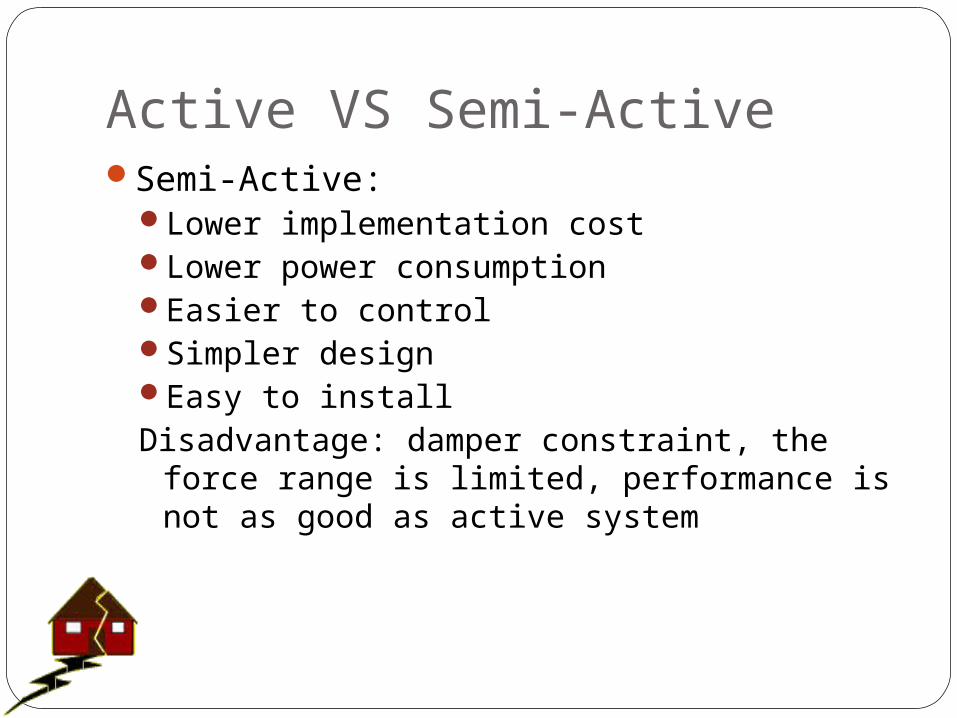
Active VS Semi-ActiveSemi-Active:
Lower implementation costLower power consumptionEasier to controlSimpler designEasy to install Disadvantage: damper constraint, the force
range is limited, performance is not as good as active system
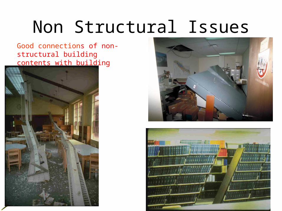
Non Structural IssuesGood connections of non-structural building contents with building