Embed Size (px)
Citation preview
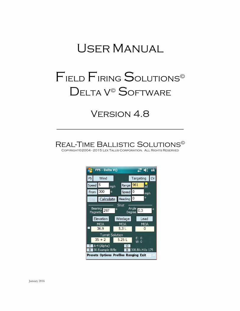
User Manual
Field Firing Solutions©
Delta V© Software
Version 4.8
Real-Time Ballistic Solutions©
Copyright©2004 - 2015 Lex Talus Corporation. All Rights Reserved
January 2016

Copyright 2014 - 2016 Lex TalusCorporation. 2nd Edition. All rightsreserved. No part of this publication may bereproduced, distributed, or transmitted inany form or by any means, includingphotocopying, recording, or otherelectronic or mechanical methods, withoutthe prior written permission of Lex TalusCorporation except as otherwise permittedby U.S. copyright law. Provided, however,that owners of the software which is thesubject of this manual are grantedpermission to create a copy of part or all ofthis manual as an aid to learning or using thesoftware.
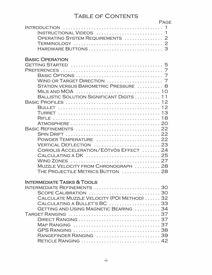
Table of Contents Page
Introduction . . . . . . . . . . . . . . . . . . . . . . . . . . . . . . . . . . . . . . . 1 Instructional Videos . . . . . . . . . . . . . . . . . . . . . . . . . . 1 Operating System Requirements . . . . . . . . . . . . . . . 2 Terminology . . . . . . . . . . . . . . . . . . . . . . . . . . . . . . . . . . . 2 Hardware Buttons . . . . . . . . . . . . . . . . . . . . . . . . . . . . . 3
Basic OperationGetting Started . . . . . . . . . . . . . . . . . . . . . . . . . . . . . . . . . . . . 5 Preferences . . . . . . . . . . . . . . . . . . . . . . . . . . . . . . . . . . . . . . . . 7
Basic Options . . . . . . . . . . . . . . . . . . . . . . . . . . . . . . . . . . 7 Wind or Target Direction . . . . . . . . . . . . . . . . . . . . . . 7 Station versus Barometric Pressure . . . . . . . . . . 8 Mils and MOA . . . . . . . . . . . . . . . . . . . . . . . . . . . . . . . . . 10 Ballistic Solution Significant Digits . . . . . . . . . . 11
Basic Profiles . . . . . . . . . . . . . . . . . . . . . . . . . . . . . . . . . . . . . 12 Bullet . . . . . . . . . . . . . . . . . . . . . . . . . . . . . . . . . . . . . . . . 12 Turret . . . . . . . . . . . . . . . . . . . . . . . . . . . . . . . . . . . . . . . . 13 Rifle . . . . . . . . . . . . . . . . . . . . . . . . . . . . . . . . . . . . . . . . . . 18 Atmosphere . . . . . . . . . . . . . . . . . . . . . . . . . . . . . . . . . . . 20
Basic Refinements . . . . . . . . . . . . . . . . . . . . . . . . . . . . . . . . . 22 Spin Drift . . . . . . . . . . . . . . . . . . . . . . . . . . . . . . . . . . . . . 22 Powder Temperature . . . . . . . . . . . . . . . . . . . . . . . . . 22 Vertical Deflection . . . . . . . . . . . . . . . . . . . . . . . . . . 23 Coriolis Acceleration/Eötvös Effect . . . . . . . 24 Calculating a DK . . . . . . . . . . . . . . . . . . . . . . . . . . . . . 25 Wind Zones . . . . . . . . . . . . . . . . . . . . . . . . . . . . . . . . . . . 27 Muzzle Velocity from Chronograph . . . . . . . . . . 28 The Projectile Metrics Button . . . . . . . . . . . . . . . 28
Intermediate Tasks & ToolsIntermediate Refinements . . . . . . . . . . . . . . . . . . . . . . . . . . 30
Scope Calibration . . . . . . . . . . . . . . . . . . . . . . . . . . . . 30 Calculate Muzzle Velocity (POI Method) . . . . . . 32 Calculating a Bullet’s BC . . . . . . . . . . . . . . . . . . . . 33 Getting and Using Magnetic Bearing . . . . . . . . . . 34
Target Ranging . . . . . . . . . . . . . . . . . . . . . . . . . . . . . . . . . . . . 37 Direct Ranging . . . . . . . . . . . . . . . . . . . . . . . . . . . . . . . . 37 Map Ranging . . . . . . . . . . . . . . . . . . . . . . . . . . . . . . . . . . 37 GPS Ranging . . . . . . . . . . . . . . . . . . . . . . . . . . . . . . . . . . 38 Rangefinder Ranging . . . . . . . . . . . . . . . . . . . . . . . . . 39 Reticle Ranging . . . . . . . . . . . . . . . . . . . . . . . . . . . . . . . 42
-i-
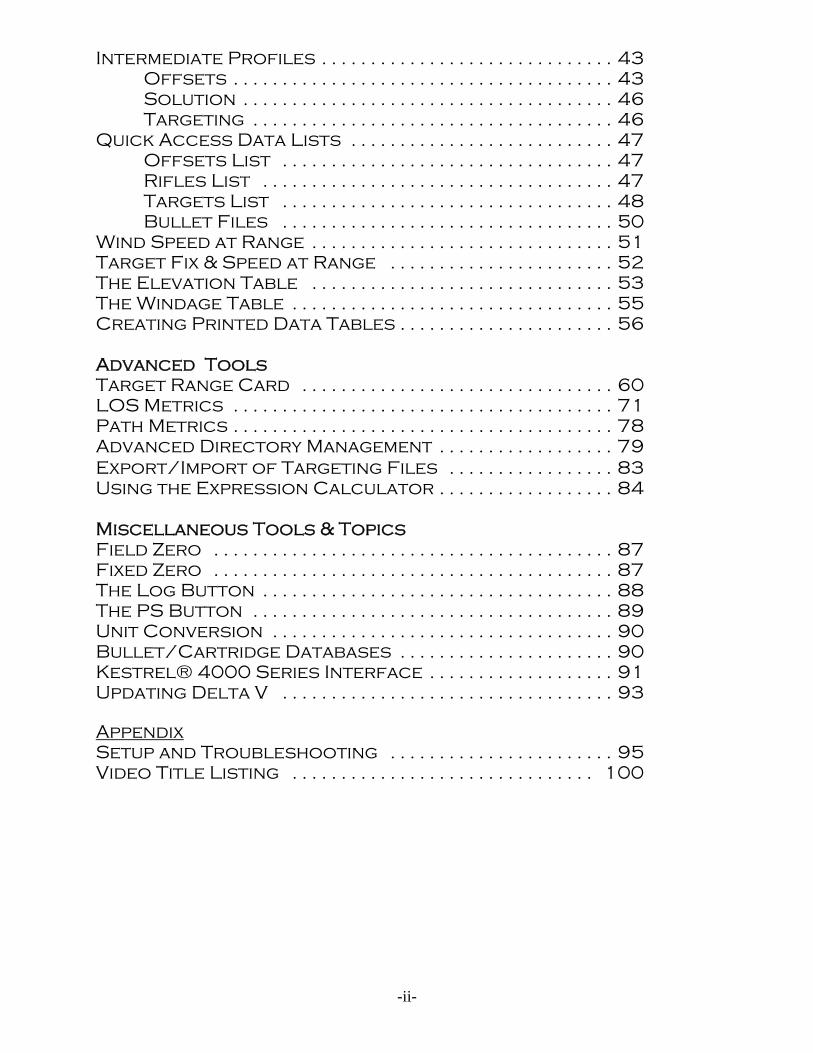
Intermediate Profiles . . . . . . . . . . . . . . . . . . . . . . . . . . . . . . 43 Offsets . . . . . . . . . . . . . . . . . . . . . . . . . . . . . . . . . . . . . . . 43 Solution . . . . . . . . . . . . . . . . . . . . . . . . . . . . . . . . . . . . . . 46 Targeting . . . . . . . . . . . . . . . . . . . . . . . . . . . . . . . . . . . . . 46
Quick Access Data Lists . . . . . . . . . . . . . . . . . . . . . . . . . . . 47 Offsets List . . . . . . . . . . . . . . . . . . . . . . . . . . . . . . . . . . 47 Rifles List . . . . . . . . . . . . . . . . . . . . . . . . . . . . . . . . . . . . 47 Targets List . . . . . . . . . . . . . . . . . . . . . . . . . . . . . . . . . . 48 Bullet Files . . . . . . . . . . . . . . . . . . . . . . . . . . . . . . . . . . 50
Wind Speed at Range . . . . . . . . . . . . . . . . . . . . . . . . . . . . . . . 51 Target Fix & Speed at Range . . . . . . . . . . . . . . . . . . . . . . . 52 The Elevation Table . . . . . . . . . . . . . . . . . . . . . . . . . . . . . . . 53 The Windage Table . . . . . . . . . . . . . . . . . . . . . . . . . . . . . . . . . 55 Creating Printed Data Tables . . . . . . . . . . . . . . . . . . . . . . 56
Advanced ToolsTarget Range Card . . . . . . . . . . . . . . . . . . . . . . . . . . . . . . . . 60 LOS Metrics . . . . . . . . . . . . . . . . . . . . . . . . . . . . . . . . . . . . . . . 71 Path Metrics . . . . . . . . . . . . . . . . . . . . . . . . . . . . . . . . . . . . . . . 78 Advanced Directory Management . . . . . . . . . . . . . . . . . . 79 Export/Import of Targeting Files . . . . . . . . . . . . . . . . . 83 Using the Expression Calculator . . . . . . . . . . . . . . . . . . 84
Miscellaneous Tools & TopicsField Zero . . . . . . . . . . . . . . . . . . . . . . . . . . . . . . . . . . . . . . . . . 87 Fixed Zero . . . . . . . . . . . . . . . . . . . . . . . . . . . . . . . . . . . . . . . . . 87 The Log Button . . . . . . . . . . . . . . . . . . . . . . . . . . . . . . . . . . . . 88 The PS Button . . . . . . . . . . . . . . . . . . . . . . . . . . . . . . . . . . . . . 89 Unit Conversion . . . . . . . . . . . . . . . . . . . . . . . . . . . . . . . . . . . 90 Bullet/Cartridge Databases . . . . . . . . . . . . . . . . . . . . . . 90 Kestrel® 4000 Series Interface . . . . . . . . . . . . . . . . . . . 91 Updating Delta V . . . . . . . . . . . . . . . . . . . . . . . . . . . . . . . . . . 93
AppendixSetup and Troubleshooting . . . . . . . . . . . . . . . . . . . . . . . 95 Video Title Listing . . . . . . . . . . . . . . . . . . . . . . . . . . . . . . . 100
-ii-
Introduction
This ballistic software runs on a small, hand-held PDA and is used to obtain areal-time firing solution in the field based upon current atmospheric and target data. The trajectory computation engine has been shown to be extraordinarily accurate evenfor ultra-long range applications assuming two conditions: 1) that the input values arevalid, and 2) that the bullet selected is itself capable of traversing the transonic regionin stable fashion. The basic output of the program is, of course, the specificinformation needed for a complete firing solution: elevation, windage, lead, or hold-off. Elevation is given in terms of an MOA or Mil adjustment and an actual turretscale equivalent is provided; windage is output in terms MOA or Mil for scopeadjustment and/or for a wind correction hold-off with either a mil-dot or MOAcalibrated reticle; lead is the hold-off correction needed for a moving target given interms of Mils or, optionally, in MOA to accommodate the scope that has MOAturrets but a Mil reticle. Beyond the basic firing solution, the program provides anarray of other data in the form of tables, both displayed and printable, and tools torefine input variables. In sum, the software provides very complete coverage of thesubject of extreme long range shooting..
Instructional Videos
The program is not “complex”, but is, as mentioned, complete with a numberof tools useful to the long range and ultra-long range shooter. Some tools require afair amount of time to learn but are necessary to generate precise data that will beinput into the program. The precision of this data is important if the user expects tomake hits on targets at range. This manual will aid in the user’s understanding of notonly the software but external ballistics in general. In addition to this manual, thereare over 30 instructional videos on the Lex Talus website covering most aspects of thesoftware. An attempt was made to break the topics into discrete parts to permitvideos of ten to fifteen minutes in length and for the most part that objective wasachieved although a couple of the videos are somewhat more lengthy. The user isurged to view each video to gain a comprehensive understanding of how to use thesoftware. After completing the videos and reading this manual, the user should havean extremely good understanding of long range ballistics in general and this softwarein particular. You can find the videos at: http://www.lextalus.com/videos.html
1
Operating System Requirements
Version 4 of the software is designed to run on the following operatingsystems: Windows Mobile 5.0, and above with Windows Mobile 6.x (all versions)being the preferred operating system. In addition, .NET Compact Framework 2.0must be loaded on the PDA. In newer PDAs with Windows Mobile 6.x this supportsoftware is part of the ROM but in the older PDAs the software needs to bedownloaded from Microsoft and installed. The software is available free fromMicrosoft and the link for the download can be found on the Lex Talus website(www.lextalus.com) in the Support section.
Terminology: Accept, Abort, OK, Done, Close, Kill
As the user accesses the various pages and forms of the program, he will notethat closing the form is sometimes accomplished with a “Done” button or menu item;sometimes the menu provides a “Close” or a “Kill” option; most forms have an“OK” at the top of the page and most forms offer the user a choice of “Accept” or“Abort”. What do these words mean in the context of this program?
Forms that allow the user to input data that can be used by the program willalmost always have “Accept” or “Abort” as the menu items that will allow the user toclose the form and exit. “Accept” means to accept the data that is on the form andmodify the existing state of the software with the new data in subsequentcomputations. “Abort” means to reject any data in the form and return to theprevious display without change to the computational environment. On forms thathave an “OK” at the top, choosing OK is the same as choosing “Abort”. The reasonfor this is to make the modification of existing data an unambiguous act on the part ofthe user. Where data can be accepted, the user must affirmatively “Accept” it.
On some forms there isn’t “Accept” or “Abort” options. These formsgenerally do not import data into the computational environment. For example, theuser can choose to use the “Calculator” (Main page: Options, Tools, Calculator). When he is finished, he simply clicks “Done” and the calculator closes. There isnothing to import; the results of the calculation are left on that form and not usedelsewhere. A couple of the forms have a check box to enable the program to use theresults of the calculations made coupled with a “Done” button. Tapping the “Done”button will close the form and if the user has so elected, the results of the work therewill be available for use in the computations.
Three of the forms have a “Kill” option to close the form - those related toGPS, Kestrel® and Rangefinder functions. These three forms have to do with getting
2
data from outside the PDA through serial ports to various pages of the program. “Kill” means to kill all processes associated with receiving serial data, close the port,and close the form. However, it is possible to open a serial port and then close theform with those processes running in the background. When the user clicks the“Start” menu item he is activating a serial port which opens and awaits the receipt ofdata. At this point the “Kill” menu item changes to “Close” and should the userchoose to “Close” the form, the serial port remains open to continue data reception. In this way, other parts of the program can get GPS, Kestrel®, and rangefinder datawithout the user having to be directly in the GPS, Kestrel®, or rangefinder forms. These devices are essentially running in the background and the program is getting theincoming data, parsing it and distributing it to other parts of the program that use thisdata. To stop the processes, the user returns to the original form, selects the “Stop”menu item at which time the “Close” menu item changes back to “Kill” and selecting“Kill” stops all related processes and closes the form.
Hardware Buttons
Most Pocket PC type PDAs have hardware buttons that can be programmed(in addition to the button cluster that generally controls the cursor and includes acentral button that functions as an Enter key.) The manufacturer of the PDA maydedicate any or all of the hardware buttons to specific functions at which point thebuttons will ignore any attempt by the software to change or temporarily alter whatthe button does when pushed. The software attempts to program available, but howany particular button is named by the manufacturer or whether it is available to theprogram to modify its function cannot be known in advance. It depends upon theparticular device. The user is advised to experiment with available buttons on thevarious forms to see what, if anything, the buttons will do. If the PDA manufacturerhas hard coded the button to a particular function, it is possible that pressing thebuttons will have no effect in the program. If the manufacturer has allowed thebuttons to remain programmable, you will have to figure out what each button does inas much as the position of the various buttons is not uniform among manufacturers.
3

Basic Operation
4
Getting Started
To use this program in its most basic form and without paying attention to thevarious tools and refinements available, but merely to compute a basic firing solution,the user need only input five sets of data and access only two pages of the program -the main page and the presets page. On the Presets page (click on “Presets” on theMain page menu) enter the following:
1. Atmospheric data consisting of the local station pressure (or theBarometric pressure and an altitude), the current temperature and humidity.
2. Bullet data consisting of the muzzle velocity, bullet weight, bullet ballisticcoefficient. Leave the DK set at the default of 0.5 until a custom DKhas been computed. (This is explained in the “Calculating a DK”section.) The muzzle velocity must be measured by the shooter; amanufacturer’s published muzzle velocity is not sufficient. However, themanufacturer’s published bullet weight and ballistic coefficient issufficient at least at the beginning. Just ensure that the ballisticcoefficient is based upon the G1 drag function. Almost all, if not all, bullet manufacturers publish a G1 ballistic coefficient so if it doesn’tstate to the contrary, the published ballistic coefficient most probably isG1 based. (Later the user will want to calculate his own ballisticcoefficient using the tools provided in the program. In the meantime,don’t be afraid to vary the ballistic coefficient if doing so improves thepredictive ability of the program. Manufacturers using optimisticballistic coefficient figures are not an unheard of phenomenon and inany case, the drag function on which their calculations are based isundoubtedly not the drag function used in this software.)
3. Scope data consisting of the scope height above the centerline of thebore and the range at which the scope is zeroed. To get the scopeheight, find a centrally located place on the scope and measure from thecenter line of the scope tube straight down to the centerline of the bore. It is not necessary to a two decimal point precision measurement; ameasurement to the nearest tenth inch is more than sufficient.
The foregoing data will not change (or will change slowly in the case oftemperature and pressure) and generally can be left alone unless the shooting sessionlasts more than a couple of hours. In that case it’s best to recheck pressure andtemperature and modify the data as necessary. (Note that the Presets page alsocontains Atmosphere, Bullet and Scope buttons to access the profiles of the same
5
names. The topic of profiles is taken up later in this manual.)
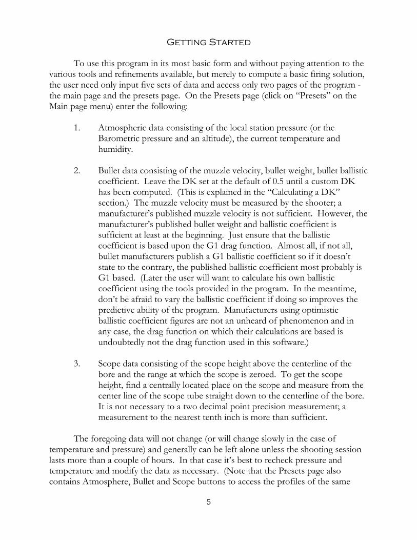
After entry of the Preset data, tap “Accept” and move back to the main page. Once there, enter:
4. The target range and, if the target ismoving, its speed and heading. Theprogram will use these to calculate aLead solution;
5. The wind speed and direction. Remember that wind is called from itssource, i.e., where it is coming from,not where it’s heading and is alwaysrelative to the direction of the target.. The program will compute the cross-wind component of the wind and usethat to compute a windage correctionvalue.
Following the entry of this data on the main page, tap the “Calculate” button. The results of the computation will be shown right below the “Elevation”, “Windage”and “Lead” buttons. These figures represent the firing solution for the data input. Dial the indicated elevation and windage, hold the lead, and shoot. If the target iswithin 500 yards, the solution will be close.
6
Preferences
Basic Options
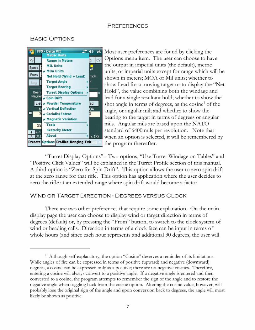
Most user preferences are found by clicking theOptions menu item. The user can choose to havethe output in imperial units (the default), metricunits, or imperial units except for range which will beshown in meters; MOA or Mil units; whether toshow Lead for a moving target or to display the “NetHold”, the value combining both the windage andlead for a single resultant hold; whether to show theshot angle in terms of degrees, as the cosine1 of theangle, or angular mil; and whether to show thebearing to the target in terms of degrees or angularmils. Angular mils are based upon the NATOstandard of 6400 mils per revolution. Note thatwhen an option is selected, it will be remembered bythe program thereafter.
“Turret Display Options” - Two options, “Use Turret Windage on Tables” and“Positive Click Values” will be explained in the Turret Profile section of this manual. A third option is “Zero for Spin Drift”. This option allows the user to zero spin driftat the zero range for that rifle. This option has application where the user decides tozero the rifle at an extended range where spin drift would become a factor.
Wind or Target Direction - Degrees versus Clock
There are two other preferences that require some explanation. On the maindisplay page the user can choose to display wind or target direction in terms ofdegrees (default) or, by pressing the “From” button, to switch to the clock system ofwind or heading calls. Direction in terms of a clock face can be input in terms ofwhole hours (and since each hour represents and additional 30 degrees, the user will
1 Although self-explanatory, the option “Cosine” deserves a reminder of its limitations. While angles of fire can be expressed in terms of positive (upward) and negative (downward)degrees, a cosine can be expressed only as a positive; there are no negative cosines. Therefore,entering a cosine will always convert to a positive angle. If a negative angle is entered and thenconverted to a cosine, the program attempts to remember the sign of the angle and to restore thenegative angle when toggling back from the cosine option. Altering the cosine value, however, willprobably lose the original sign of the angle and upon conversion back to degrees, the angle will mostlikely be shown as positive.
7
necessarily have to be satisfied with a wind call plus/minus 15 degrees), decimal hoursor hours and minutes. For example, the user can input 10.5 or 10:30. The two areequivalent and both equal 315 degrees. When moving between the two formats,degrees will be rounded to the nearest 0.5 degree. This is because the program roundsdecimal degrees to the nearest whole minute. So converting 270.8 degrees will beshown as 9:02 hours even though it is closer to 9:01.5 hours. Converting 9:02 hoursback to degrees will yield 271 degrees, the correct conversion of 9:02 hours. Bothwind and target headings work the same way.
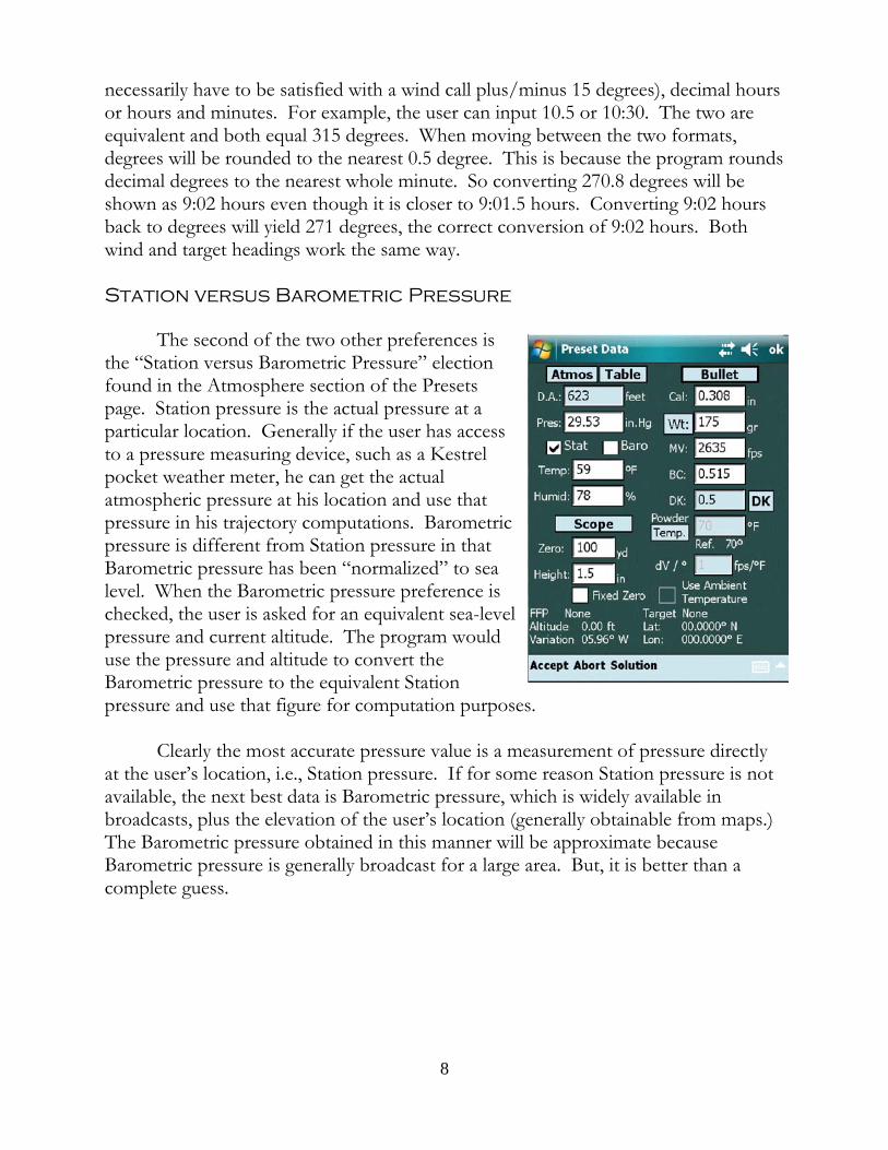
Station versus Barometric Pressure
The second of the two other preferences isthe “Station versus Barometric Pressure” electionfound in the Atmosphere section of the Presetspage. Station pressure is the actual pressure at aparticular location. Generally if the user has accessto a pressure measuring device, such as a Kestrelpocket weather meter, he can get the actualatmospheric pressure at his location and use thatpressure in his trajectory computations. Barometricpressure is different from Station pressure in thatBarometric pressure has been “normalized” to sealevel. When the Barometric pressure preference ischecked, the user is asked for an equivalent sea-levelpressure and current altitude. The program woulduse the pressure and altitude to convert theBarometric pressure to the equivalent Stationpressure and use that figure for computation purposes.
Clearly the most accurate pressure value is a measurement of pressure directlyat the user’s location, i.e., Station pressure. If for some reason Station pressure is notavailable, the next best data is Barometric pressure, which is widely available inbroadcasts, plus the elevation of the user’s location (generally obtainable from maps.) The Barometric pressure obtained in this manner will be approximate becauseBarometric pressure is generally broadcast for a large area. But, it is better than acomplete guess.
8
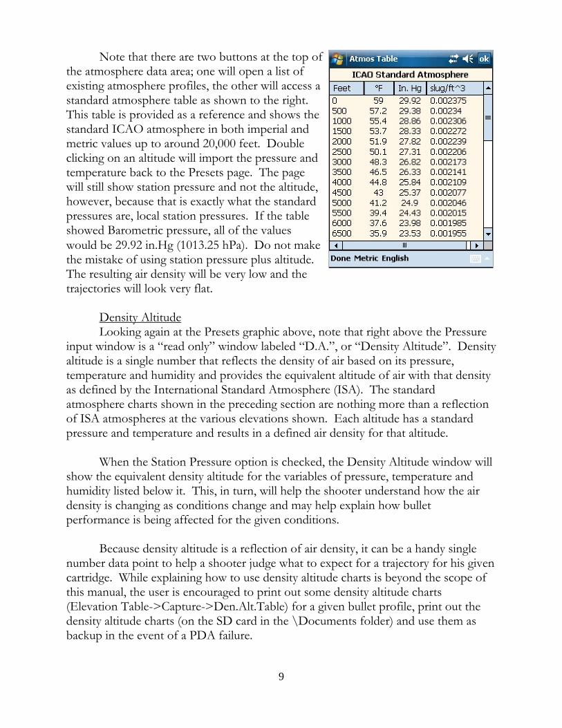
Note that there are two buttons at the top ofthe atmosphere data area; one will open a list ofexisting atmosphere profiles, the other will access astandard atmosphere table as shown to the right. This table is provided as a reference and shows thestandard ICAO atmosphere in both imperial andmetric values up to around 20,000 feet. Doubleclicking on an altitude will import the pressure andtemperature back to the Presets page. The pagewill still show station pressure and not the altitude,however, because that is exactly what the standardpressures are, local station pressures. If the tableshowed Barometric pressure, all of the valueswould be 29.92 in.Hg (1013.25 hPa). Do not makethe mistake of using station pressure plus altitude. The resulting air density will be very low and thetrajectories will look very flat.
Density AltitudeLooking again at the Presets graphic above, note that right above the Pressure
input window is a “read only” window labeled “D.A.”, or “Density Altitude”. Densityaltitude is a single number that reflects the density of air based on its pressure,temperature and humidity and provides the equivalent altitude of air with that densityas defined by the International Standard Atmosphere (ISA). The standardatmosphere charts shown in the preceding section are nothing more than a reflectionof ISA atmospheres at the various elevations shown. Each altitude has a standardpressure and temperature and results in a defined air density for that altitude.
When the Station Pressure option is checked, the Density Altitude window willshow the equivalent density altitude for the variables of pressure, temperature andhumidity listed below it. This, in turn, will help the shooter understand how the airdensity is changing as conditions change and may help explain how bulletperformance is being affected for the given conditions.
Because density altitude is a reflection of air density, it can be a handy singlenumber data point to help a shooter judge what to expect for a trajectory for his givencartridge. While explaining how to use density altitude charts is beyond the scope ofthis manual, the user is encouraged to print out some density altitude charts(Elevation Table->Capture->Den.Alt.Table) for a given bullet profile, print out thedensity altitude charts (on the SD card in the \Documents folder) and use them asbackup in the event of a PDA failure.
9
[Note: When using a Kestrel connected to the program, do not expect theDensity Altitude as calculated by the Kestrel unit to necessarily agree with theprogram’s calculation. The problem is that the Kestrel does not send the actualpressure, temperature and humidity to the program; rather, it sends rounded off values. For example, when the program calculates the pressure at sea level, it calculates it as29.92115526565 in. Hg., uses that value in its calculations but displays the roundedfigure of 29.92. The use of rounded figure for calculation purposes will result in aslight error in density altitude. When using the Kestrel, pressure is rounded to twosignificant digits, temperature and humidity values are rounded to one significant digit,and then these values are sent to the program. The program will use the roundedvalues, but the resulting density altitude calculation will not match that of the Kestrelwhich is using values of greater precision internally.]
Mils and MOA
Immediately below the Elevation and Windage buttons are the main outputwindows for the firing solution. The solution will be given in terms of Mils or MOAdepending upon user preferences. When the user chooses Mils as the basic unit forexpressing elevation and windage data, all solution windows are displayed in terms ofMils. This makes sense if the user has a “coordinated” scope setup, i.e., where theturret scale matches the reticle scale. If both are the same then it is appropriate forthe solution to have common units of measure. So, if the user has a Mil-dot reticleand a Mil turret, he will prefer that the firing solution be given in terms of Mil units. Conversely, if the user has an MOA turret and an MOA reticle, he will prefersolutions given in MOA units.
For historical reasons, many shooters have scopes that have MOA turrets but aMil reticle. This uncoordinated arrangement creates certain challenges for appropriatedata display. Depending upon whether the shooter is going to dial or hold the windsuch decision dictates whether the wind solution should be displayed in MOA or Milunits. The situation becomes slightly more complex when the target is moving. Willthe shooter dial the wind and hold a lead or should both the wind and lead be held inwhich case the shooter may want a resultant hold off value that comprises the nethold after combining both wind and lead?
The program attacks the problem by first allowing the user to toggle the Leadunits between Mil and MOA. Whichever is selected is deemed to be the units of thereticle. Upon selecting Lead units different from the Windage units, a units togglebutton for Windage also appears thus allowing the user to 1) keep the units suitablefor dialing the wind; or, 2) change the units to those of the reticle so that windage maybe held. This solution works fine if the target is stationary. But when the target ismoving and a cross wind is present, both the Windage and Lead will have hold off
10
values. Again, two choices present themselves: 1) dial the wind and hold the lead; or,2) combine both wind and lead values for a net hold off value. The user can either dothe math mentally or choose the “Net Hold” option which converts the Lead buttonand data window to a “Net Hold” function and displays the net hold off value therebyaccounting for both the wind and lead corrections. Where target speed is zero, theNet Hold window can be used to display only the wind hold off value.
Ballistic Solution Significant Digits
To the immediate left of the elevation solution window is a small unlabeledbutton whose function is to toggle between the one and two significant digits of theelevation and windage solutions. The reason for this option is that some shooterswant the elevation solution to be expressed with one significant digit so that the Milsolution can be directly interpreted as a turret setting. For example, a solution of 8.1Mils is directly understood as dialing to the number “8” on the turret plus one tenthof a Mil, one more click. (Of course this only works if the turret click value is a true0.1 Mil per click.) Other shooters want to see the amount rounded so that they can“favor” either high or low depending upon the value rounded. If, for example, theactual solution was 8.06, the nearest value is rounded up to 8.1 which means that theshooter will dial slightly more than needed and can “favor low”. If, however, the 8.1was rounded down from 8.14, the shooter would favor high due to the fact that thesolution was actually a little more than was dialed.
11
Basic Profiles
At the core of this software is the concept of the “profile” which is a text filethat contains data that is logically related. These profiles and all the data they containmay be loaded by simply opening the file. There are a number of profiles that can becreated, some essential, some merely convenient. As the user reads through thissection, be aware that all profiles, once completed and saved, can be loadedautomatically upon exit by checking the “Load File Upon Close” box to immediatelyuse the stored data.
A. The Bullet ProfileThe user is encouraged to complete a bullet profile for each bullet he uses. A
completed profile for a relatively common .308 Win. cartridge is shown. It isimportant that all of the data items are filled in as each is used by the program tocompute some part of the trajectory. The failure to complete the form or inputerroneous data will cause the program to either malfunction or yield incorrect results. Of particular note is the “Min. Twist” data item. When building a Rifle Profile, theuser will input the rifles actual twist. In the absence of a rifle profile, the program willlook to the bullet profile for the twist information. The program uses the twistinformation in portions of the trajectory computation and the failure to include it willcause the program to fail. So in completing the Bullet Profile use either the minimumtwist as recommended for that particular bullet or use a twist that is representative ofthe twist rates of the rifles generally used by the user that shoot that bullet.
The DK data item is set to the default of 0.5. The value will change only whenthe user performs the necessary field experimentation and calculation to yield anothernumber as explained in the “Calculating a DK” section of this manual.
The “Powder Temperature” is the temperature at which the muzzle velocitywas obtained. Remember that when this data loads, the muzzle velocity may change ifthe ambient temperature is different from the temperature at which the data wascollected. The change of muzzle velocity is based upon the content of the dV/N textbox. This means “change of velocity per degree” and requires a value representingthe powder sensitivity to temperature changes. The velocity will be the same units asused to express muzzle velocity; the temperature units will be the same as those usedto express the powder temperature. The value that is used is a result of shooterexperimentation. Measure the velocity of the particular load on a cool or cold day;repeat on a warm or hot day. Take the difference in muzzle velocities and divide bythe difference in temperatures. The result will be the change of velocity per degree.
Finally note the bullet length text box. If the bullet length is unknown, checkthe bullet database to see if it is listed, or simply take apart a cartridge and measure the
12

length with a set of calipers. The length of the bullet is required to compute spin driftas a function of barrel twist rate. In the absence of a bullet length, enter zero and thedefault spin drift function will be used in which event spin drift will be the same for alltwist rates. While not exact, it will be close. Example: a typical .308 Win. 175 gr.Sierra MK bullet leaving a barrel at 2600 fps with a 12" twist will experience spin driftof about 8 inches at 1000 yards. The same bullet leaving a 10" twist barrel will havearound 12 inches of spin drift. The default spin drift function will calculate about 10inches of drift. It is a reasonably close value.
B. The Turret Profile
1. The Simple Turret ProfileThe purpose of the turret profile is to provide an elevation and windage that is
correct for a given scope. To demonstrate the problem, assume that the calculatedelevation required for a particular range and cartridge is 11.6 Mil (41 MOA). If thescope’s click value is correct, the calculated value is dialed. If, however, the click valueon a particular user’s scope is not 0.1 Mil/click, but instead is 0.105 Mils per click,dialing 11.6 Mils solution would result in an actual movement of the reticle equal to12.18 Mils (0.105 Mil/click x 116 clicks.), 0.58 Mils too much. The bullet is going tohit almost 0.6 Mils high.
The way to deal with turret click value errors is to create a turret profile wherethe user will input the “nominal” click value, i.e., the value that the manufacturerintends it to be (in our example 0.1 Mil/click) and the “actual” click value, onecomputed by the user when using the scope calibration techniques explainedelsewhere in this manual. With these two values, the program can compute not onlythe required elevation, but the “turret elevation”, i.e., the elevation that needs to bedialed on the user’s scope in order to move the reticle the calculated amount. Goingback to the above example, for this particular scope in order to actually move thereticle 11.6 Mils, the user would only have to dial 11 Mils (11 Mils x 0.105 = 11.55Mils). The turret profile, when loaded into the program, will calculate the correctelevation the owner of this scope must dial and present that value in the “TurretSolution” windows on the main page.
In order to make a simple turret profile, the user need only calibrate his scopeto determine the “actual” click values, put in both nominal and actual elevation andwindage in the profile, state the zero range and scope height. The profile is finishedand usable. For the “simple turret profile,” the rest of the profile form can beignored. Everything below the horizontal line shown in the Turret Profiler (see nextgraphic) is optional.
2. The Complete Turret ProfileIt is possible to convert an elevation calculation into the equivalent turret scale
13
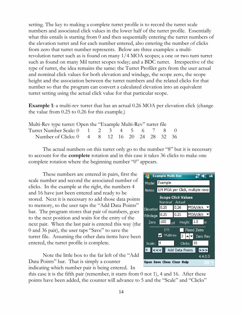
setting. The key to making a complete turret profile is to record the turret scalenumbers and associated click values in the lower half of the turret profile. Essentiallywhat this entails is starting from 0 and then sequentially entering the turret numbers ofthe elevation turret and for each number entered, also entering the number of clicksfrom zero that turret number represents. Below are three examples: a multi-revolution turret such as is found on many 1/4 MOA scopes; a one or two turn turretsuch as found on many Mil turret scopes today; and a BDC turret. Irrespective of thetype of turret, the idea remains the same: the Turret Profiler gets from the user actualand nominal click values for both elevation and windage, the scope zero, the scopeheight and the association between the turret numbers and the related clicks for thatnumber so that the program can convert a calculated elevation into an equivalentturret setting using the actual click value for that particular scope.
Example 1: a multi-rev turret that has an actual 0.26 MOA per elevation click (changethe value from 0.25 to 0.26 for this example.)
Multi-Rev type turret: Open the “Example Multi-Rev” turret fileTurret Number Scale: 0 1 2 3 4 5 6 7 8 0 Number of Clicks: 0 4 8 12 16 20 24 28 32 36
The actual numbers on this turret only go to the number “8” but it is necessaryto account for the complete rotation and in this case it takes 36 clicks to make one complete rotation where the beginning number “0” appears.
These numbers are entered in pairs, first thescale number and second the associated number ofclicks. In the example at the right, the numbers 4and 16 have just been entered and ready to bestored. Next it is necessary to add those data pointsto memory, so the user taps the “Add Data Points”bar. The program stores that pair of numbers, goesto the next position and waits for the entry of thenext pair. When the last pair is entered this way (the0 and 36 pair), the user taps “Save” to save theturret file. Assuming the other data items have beenentered, the turret profile is complete.
Note the little box to the far left of the “AddData Points” bar. That is simply a counterindicating which number pair is being entered. Inthis case it is the fifth pair (remember, it starts from 0 not 1), 4 and 16. After thesepoints have been added, the counter will advance to 5 and the “Scale” and “Clicks”
14
windows will be blank waiting for the next pair of numbers.
Important Note: The Multi-Rev turret is the simplest to make since werecord the scale numbers and their respective clicks for a single turn only. Once the Scale/Clicks data has been entered for a single, complete revolutionthat part of the data entry is done. Do not continue to enter data past thatsingle revolution.
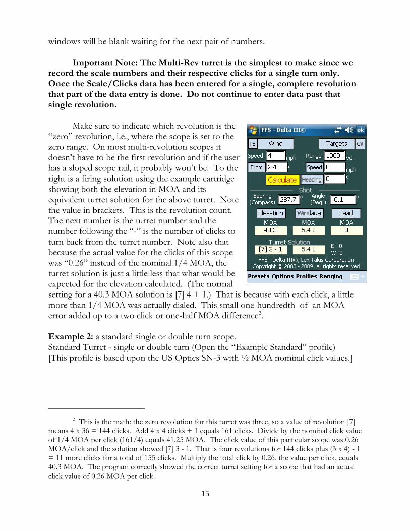
Make sure to indicate which revolution is the“zero” revolution, i.e., where the scope is set to thezero range. On most multi-revolution scopes itdoesn’t have to be the first revolution and if the userhas a sloped scope rail, it probably won’t be. To theright is a firing solution using the example cartridgeshowing both the elevation in MOA and itsequivalent turret solution for the above turret. Notethe value in brackets. This is the revolution count. The next number is the turret number and thenumber following the “-” is the number of clicks toturn back from the turret number. Note also thatbecause the actual value for the clicks of this scopewas “0.26” instead of the nominal 1/4 MOA, theturret solution is just a little less that what would beexpected for the elevation calculated. (The normalsetting for a 40.3 MOA solution is [7] 4 + 1.) That is because with each click, a littlemore than 1/4 MOA was actually dialed. This small one-hundredth of an MOAerror added up to a two click or one-half MOA difference2.
Example 2: a standard single or double turn scope.Standard Turret - single or double turn (Open the “Example Standard” profile)[This profile is based upon the US Optics SN-3 with ½ MOA nominal click values.]
2 This is the math: the zero revolution for this turret was three, so a value of revolution [7]means 4 x 36 = 144 clicks. Add 4 x 4 clicks + 1 equals 161 clicks. Divide by the nominal click valueof 1/4 MOA per click (161/4) equals 41.25 MOA. The click value of this particular scope was 0.26MOA/click and the solution showed [7] 3 - 1. That is four revolutions for 144 clicks plus (3 x 4) - 1= 11 more clicks for a total of 155 clicks. Multiply the total click by 0.26, the value per click, equals40.3 MOA. The program correctly showed the correct turret setting for a scope that had an actualclick value of 0.26 MOA per click.
15
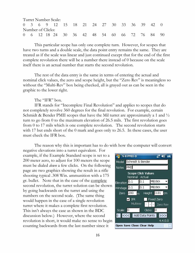
Turret Number Scale: 0 3 6 9 12 15 18 21 24 27 30 33 36 39 42 0 Number of Clicks:0 6 12 18 24 30 36 42 48 54 60 66 72 76 84 90
This particular scope has only one complete turn. However, for scopes thathave two turns and a double scale, the data point entry remains the same. They aretreated as if the scale was linear and just continued except that for the end of the firstcomplete revolution there will be a number there instead of 0 because on the scaleitself there is an actual number that starts the second revolution.
The rest of the data entry is the same in terms of entering the actual andnominal click values, the zero and scope height, but the “Zero Rev” is meaningless sowithout the “Multi-Rev” box being checked, all is grayed out as can be seen in thegraphic to the lower right.
The “IFR” box.IFR stands for “Incomplete Final Revolution” and applies to scopes that do
not completely revolve 360 degrees for the final revolution. For example, certainSchmidt & Bender PMII scopes that have the Mil turret are approximately a 1 and ½turn to go from 0 to the maximum elevation of 26.5 mils. The first revolution goesfrom 0 to 17 mils which is one complete revolution. The second revolution startswith 17 but ends short of the 0 mark and goes only to 26.5. In these cases, the usermust check the IFR box.
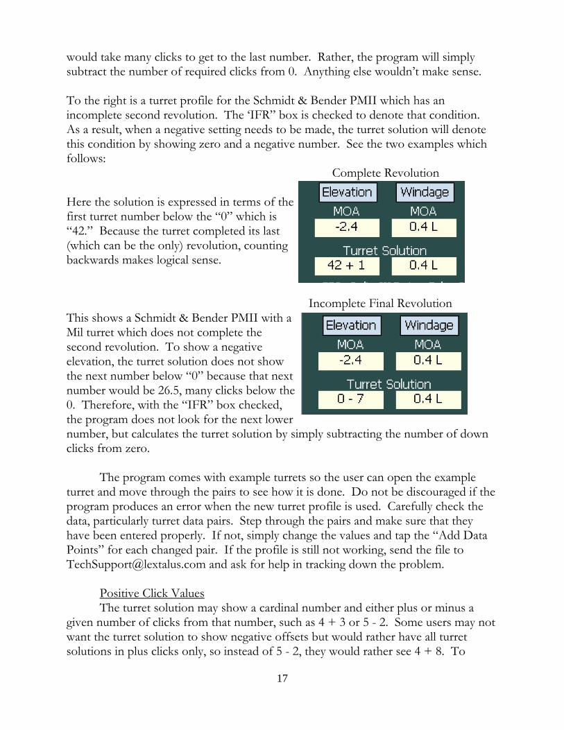
The reason why this is important has to do with how the computer will convertnegative elevations into a turret equivalent. Forexample, if the Example Standard scope is set to a200 meter zero, to adjust for 100 meters the scopemust be dialed down a few clicks. On the followingpage are two graphics showing the result in a rifleshooting typical .308 Win. ammunition with a 175gr. bullet. Note that in the case of the completesecond revolution, the turret solution can be shownby going backwards on the turret and using thenumbers on the second scale. (The same thingwould happen in the case of a single revolutionturret where it makes a complete first revolution. This isn’t always the case as shown in the BDCdiscussion below.) However, where the secondrevolution is short, it would make no sense to begincounting backwards from the last number since it
16
would take many clicks to get to the last number. Rather, the program will simplysubtract the number of required clicks from 0. Anything else wouldn’t make sense.
To the right is a turret profile for the Schmidt & Bender PMII which has anincomplete second revolution. The ‘IFR” box is checked to denote that condition. As a result, when a negative setting needs to be made, the turret solution will denotethis condition by showing zero and a negative number. See the two examples whichfollows:
Complete Revolution
Here the solution is expressed in terms of thefirst turret number below the “0” which is“42.” Because the turret completed its last(which can be the only) revolution, countingbackwards makes logical sense.
Incomplete Final Revolution This shows a Schmidt & Bender PMII with aMil turret which does not complete thesecond revolution. To show a negativeelevation, the turret solution does not showthe next number below “0” because that nextnumber would be 26.5, many clicks below the0. Therefore, with the “IFR” box checked,the program does not look for the next lowernumber, but calculates the turret solution by simply subtracting the number of downclicks from zero.
The program comes with example turrets so the user can open the exampleturret and move through the pairs to see how it is done. Do not be discouraged if theprogram produces an error when the new turret profile is used. Carefully check thedata, particularly turret data pairs. Step through the pairs and make sure that theyhave been entered properly. If not, simply change the values and tap the “Add DataPoints” for each changed pair. If the profile is still not working, send the file [email protected] and ask for help in tracking down the problem.
Positive Click ValuesThe turret solution may show a cardinal number and either plus or minus a
given number of clicks from that number, such as 4 + 3 or 5 - 2. Some users may notwant the turret solution to show negative offsets but would rather have all turretsolutions in plus clicks only, so instead of 5 - 2, they would rather see 4 + 8. To
17
achieve this output, choose “Positive Click Values” listed at Option->Turret DisplayOptions on the main page. With this option checked, all turret solutions will showonly positive click values except for negative elevations involving IFR turrets. Thosesolutions will continue to show a negative offset from 0.
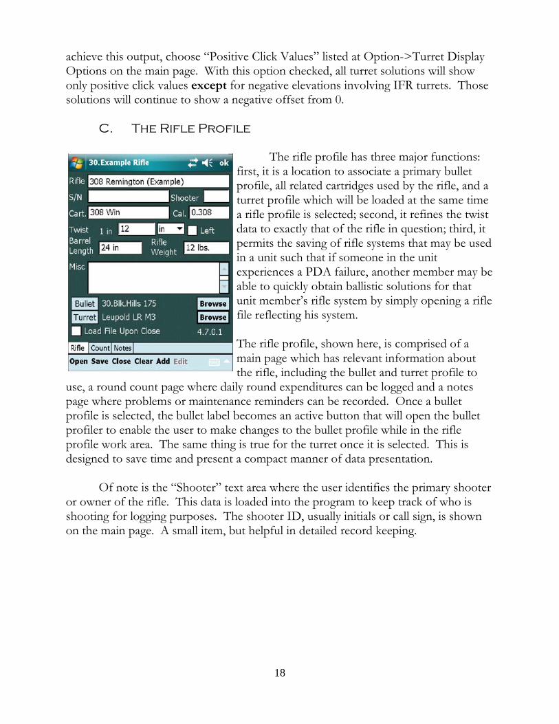
C. The Rifle Profile
The rifle profile has three major functions:first, it is a location to associate a primary bulletprofile, all related cartridges used by the rifle, and aturret profile which will be loaded at the same timea rifle profile is selected; second, it refines the twistdata to exactly that of the rifle in question; third, itpermits the saving of rifle systems that may be usedin a unit such that if someone in the unitexperiences a PDA failure, another member may beable to quickly obtain ballistic solutions for thatunit member’s rifle system by simply opening a riflefile reflecting his system.
The rifle profile, shown here, is comprised of amain page which has relevant information aboutthe rifle, including the bullet and turret profile to
use, a round count page where daily round expenditures can be logged and a notespage where problems or maintenance reminders can be recorded. Once a bulletprofile is selected, the bullet label becomes an active button that will open the bulletprofiler to enable the user to make changes to the bullet profile while in the rifleprofile work area. The same thing is true for the turret once it is selected. This isdesigned to save time and present a compact manner of data presentation.
Of note is the “Shooter” text area where the user identifies the primary shooteror owner of the rifle. This data is loaded into the program to keep track of who isshooting for logging purposes. The shooter ID, usually initials or call sign, is shownon the main page. A small item, but helpful in detailed record keeping.
18
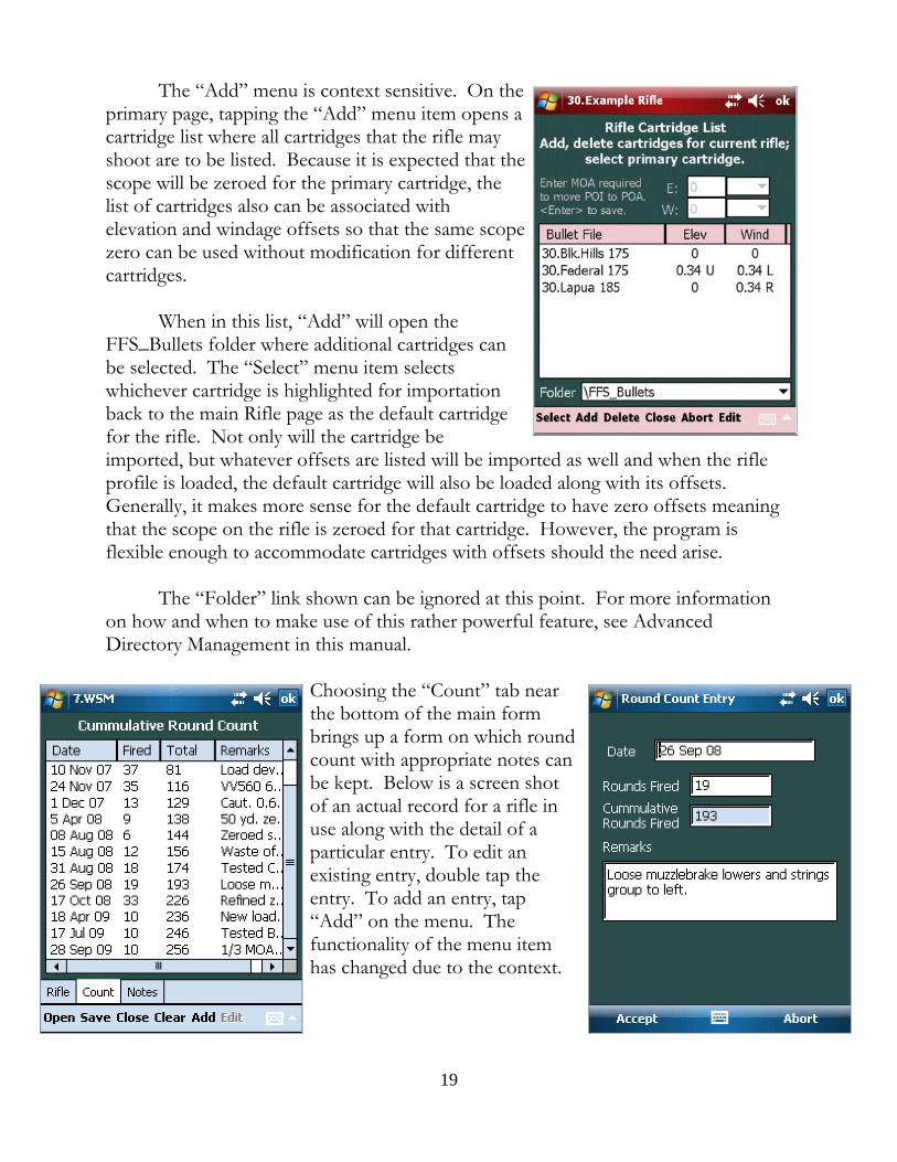
The “Add” menu is context sensitive. On theprimary page, tapping the “Add” menu item opens acartridge list where all cartridges that the rifle mayshoot are to be listed. Because it is expected that thescope will be zeroed for the primary cartridge, thelist of cartridges also can be associated withelevation and windage offsets so that the same scopezero can be used without modification for differentcartridges.
When in this list, “Add” will open theFFS_Bullets folder where additional cartridges canbe selected. The “Select” menu item selectswhichever cartridge is highlighted for importationback to the main Rifle page as the default cartridgefor the rifle. Not only will the cartridge beimported, but whatever offsets are listed will be imported as well and when the rifleprofile is loaded, the default cartridge will also be loaded along with its offsets. Generally, it makes more sense for the default cartridge to have zero offsets meaningthat the scope on the rifle is zeroed for that cartridge. However, the program isflexible enough to accommodate cartridges with offsets should the need arise.
The “Folder” link shown can be ignored at this point. For more informationon how and when to make use of this rather powerful feature, see AdvancedDirectory Management in this manual.
Choosing the “Count” tab nearthe bottom of the main formbrings up a form on which roundcount with appropriate notes canbe kept. Below is a screen shotof an actual record for a rifle inuse along with the detail of aparticular entry. To edit anexisting entry, double tap theentry. To add an entry, tap“Add” on the menu. Thefunctionality of the menu itemhas changed due to the context.
19
The third form available in the rifle profile can be accessed with the “Notes”tab. This is a place to include any information deemed related to the rifle system. The“Edit” menu item has a variety of editing functions. At the top of the page is a“Write” button which will allow the writing of the notes to a file which will, bydefault, contain the name of the rifle profile and be stored in the FFS_Rifle directory. The user is free, however, to name the file whatever he chooses and store it where hepleases. If the “Append” check box is checked, the existing notes will be appended toany existing text file specified. If the Append box is unchecked, the notes materialwill overwrite whatever is in an existing file.
If the user presses and holds the Write button for ½ second, the buttonfunctions as a “Read” button and will open an Open File Dialog list with all of thetext files found. Thus, in this mode the user is allowed to import any text file into theNotes text window.
D. The Atmosphere Profile
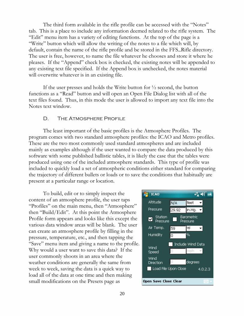
The least important of the basic profiles is the Atmosphere Profiles. Theprogram comes with two standard atmosphere profiles: the ICAO and Metro profiles. These are the two most commonly used standard atmospheres and are includedmainly as examples although if the user wanted to compare the data produced by thissoftware with some published ballistic tables, it is likely the case that the tables wereproduced using one of the included atmosphere standards. This type of profile wasincluded to quickly load a set of atmospheric conditions either standard for comparingthe trajectory of different bullets or loads or to save the conditions that habitually arepresent at a particular range or location.
To build, edit or to simply inspect thecontent of an atmosphere profile, the user taps“Profiles” on the main menu, then “Atmosphere”then “Build/Edit”. At this point the AtmosphereProfile form appears and looks like this except thevarious data window areas will be blank. The usercan create an atmosphere profile by filling in thepressure, temperature, etc., and then tapping the “Save” menu item and giving a name to the profile. Why would a user want to save this data? If theuser commonly shoots in an area where theweather conditions are generally the same fromweek to week, saving the data is a quick way toload all of the data at one time and then makingsmall modifications on the Presets page as
20
necessary. It is a time saver and nothing more. Note that the user can choosewhether to save a wind speed and direction in the profile. If a particular location has aprevailing wind, opting to include a wind speed and direction makes sense.
The user will chose whether the atmospheric pressure being saved is the actual pressure as measured on site (Station pressure) or the pressure normalize to a sea levelvalue (Barometric pressure). If barometric pressure is going to be used, by checkingthe “Barometric Pressure” box, the Altitude data window becomes writeable and theuser will need to input an altitude associated with the barometric pressure.
Once an Atmosphere Profile has been made and saved it can be quicklyaccessed by tapping “Profiles” on the main menu, then “Atmosphere” then “Load”. Whatever atmosphere profiles exist on the PDA will be listed in the dialog box. Clickon the profile of choice and the atmosphere variables contained in the profile will befed into the program. The user can check that the data has been successfullyimported by either tapping the “PS” key on the main form (upper left hand corner) orby going to the Presets page.
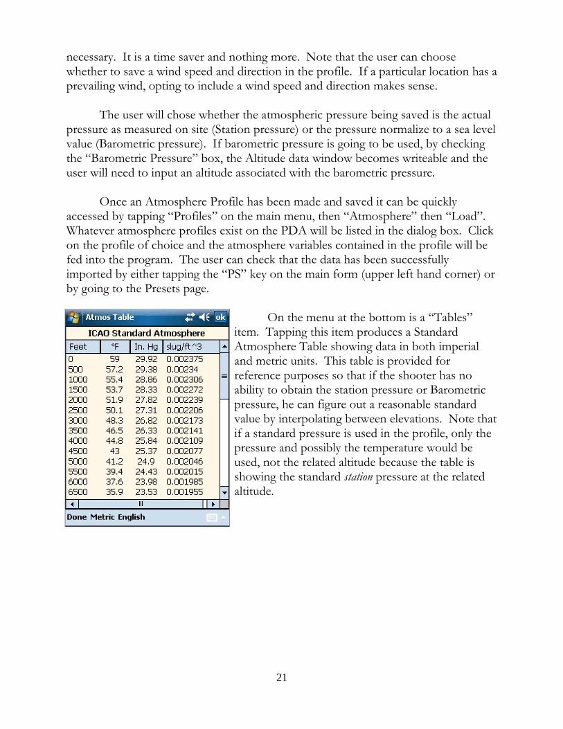
On the menu at the bottom is a “Tables”item. Tapping this item produces a StandardAtmosphere Table showing data in both imperialand metric units. This table is provided forreference purposes so that if the shooter has noability to obtain the station pressure or Barometricpressure, he can figure out a reasonable standardvalue by interpolating between elevations. Note thatif a standard pressure is used in the profile, only thepressure and possibly the temperature would beused, not the related altitude because the table isshowing the standard station pressure at the relatedaltitude.
21
Basic Ballistic Solution Refinement
While inputting the essential data on the main and Presets page will yield afiring solution, the solution calculated will be suitable for only short range shootingnot exceeding 500 meters. There are several tools added to the program to help refinethe calculated firing solution suitable for long range use.
Spin Drift
Spin drift is the movement of the bullet that occurs as a result of the fact that itis spinning about the longitudinal axis and is being subjected to gyroscopic forcesresulting from its spin and the aerodynamic forces acting upon it due to the rush of airmoving past it. Various and sundry forces arise from these circumstances, but forpurposes of this manual let it suffice to say that when the bullet stabilizes in flightafter leaving the barrel, its longitudinal axis does not point exactly forward. Forclockwise spinning bullets, the bullet comes to a point of equilibrium with itslongitudinal axis pointed slightly to the right. In other words, the longitudinal axis ofthe bullet is not exactly tracking the trajectory; the axis is slightly rotated to the rightand the relative wind is striking the bullet slightly more on its left side pushing thebullet to the right as the bullet moves downrange. The result of this is what appearsto be a drift of the bullet to the right. To have the software correct for this drift, tapthe Options menu and check Spin Drift. The program will calculate this drift and thecalculated spin drift will become part of the windage solution. You can check theamount of drift by selecting and then de-selecting Spin Drift and seeing the change inwindage.
Irrespective of the range the user intends to shot, there really isn’t a reason notto select Spin Drift and leave it selected.
Powder Temperature
A change in the ambient temperature changes the trajectory of a bullet in twoways: first, a temperature change affects the air density which directly affects theability of the bullet to move through the air. As the temperature rises, the air becomeless dense and the bullet will tend to experience less drop over the same range becauseit is bleeding off its speed at a slower rate. The reverse is also true: a drop intemperature causes the atmosphere to grow more dense, slowing the bullet faster,requiring more time to traverse the same range thereby causing the bullet drop toincrease. Bullets will tend to strike the target lower as the air becomes more dense. This direct effect of a changing temperature is handled by the program as part of theway it computes air density from the atmospheric data on the Presets page.
22
But there can also be an indirect effect of changing temperature. When thetemperature drops, powder temperature can also drop, barrel temperature drops andas a consequence of this muzzle velocity drops as well. The reverse tends to be trueas well: as temperatures increase, powder temperatures increase, barrel temperaturesincrease and bullet muzzle velocity tends to increase.
Not all powders behave the same way in this regard and some powders seem tobe affected much more that others as a result of temperature fluctuations.3 In orderto deal with this indirect effect of temperature change, an option was included thatallows the user to indicate what change of velocity occurs for the powder he uses perdegree change of temperature. This requires that the user 1) know what the ambienttemperature was when he obtained the muzzle velocity data for his particular load; 2)make some attempt through experimentation to discern how the powder he usesreacts to temperature changes; and 3) know the current temperature of the powder orat least the surrounding air. All of this data can be input by hand, but is moreconveniently stored in a Bullet Profile (discussed in the Basic Profiles section of themanual). Upon loading this profile, the program will have the data it needs to modifythe muzzle velocity of the cartridge as different atmospheric temperatures are input bythe user.
Once the “Powder Temperature” option is checked, the program will assumethat the powder temperature is the same as the ambient temperature. Alternatively,the “Use Ambient Temperature” box on the Presets page can be unchecked and theprogram will assume a powder temperature as supplied by the bullet profile or asinput by the user. This is useful during experimentation where the user can keep thecartridges at a particular temperature and specify that powder temperature irrespectiveof what the air temperature is.
Vertical Deflection
Everyone knows that a cross-wind causes a horizontal deflection of the bullet
3 The operative word here is “seems”. Hodgdon publishes data showing that its “Extreme”brand of powders are very insensitive to changes of temperature. However, the testing methodologyis not published. There is at least one article, written by Denton Bramwell in 2003, “PressureFactors: How Temperature, Powder, and Primer Affect Pressure”, that suggests that possibly risingbarrel temperature, and not rising powder temperature, is responsible for increased muzzle velocity. Powder temperature may be irrelevant or at least not significant. Find and read the article. There iscontrary data, however. Sgt. Glen Roberts, a police sniper team leader who works for the WesternAustralia Police and very careful student of exterior ballistics, has collected interesting experimentaldata indicating that changing barrel and receiver temperatures does not affect muzzle velocity, butthat changing powder temperature does. Clearly, more work in this area is warranted.
23
in the direction that the wind is blowing. It is less commonly known that a cross-windalso causes the bullet to be vertically deflected as well.
The reason why the bullet experiences a vertical deflection in a cross-wind hasto do with the fact that as the bullet exits the muzzle, within a very short distance,small enough to be measured in few calibers, the bullet noses into the wind. Thismovement of a rotating body is accompanied by either a dipping or rising of the noseof the bullet until the bullet reaches a state of equilibrium with the various forcesacting upon it and results in what is called “aerodynamic jump”4. This momentarydipping or rising alters the path of the bullet slightly either slightly uphill or slightlydownhill. For a clockwise spinning bullet, a cross-wind blowing from the left willcause the bullet to dip; a cross-wind coming from the right will cause the bullet’s tip tolift slightly as it noses into it. The result is that down range, the bullet strikes will tendto impact downward and to the right in a left wind and upward and to the left in aright wind along a line intersecting the center of the target and through the 10 and 4o’clock positions approximately. The movement is relatively small in light winds (6mph or less) but in winds 10 mph and above the vertical deflection can becomesignificant which is why it was included.
Coriolis Acceleration/Eötvös Effect
The movement of the bullet due to Coriolis acceleration is an apparenthorizontal movement that results from the fact that due to the Earth’s rotation theapparent path of the projectile will seem to curve . In the Northern Hemisphere thecurve is to the right; in the Southern Hemisphere the curve is left. In addition,shooting East or West causes the bullet to strike the target higher or lowerrespectively a phenomenon known as the Eötvös effect.5
In small arms, the Coriolis/Eötvös effects are generally ignored. It is basically atime dependent issue and since small arms projectiles are actually in the air no morethan 8 seconds for extremely long range shots, the amount of target movement issmall. Small, however, is not inconsequential. A .308 Winchester shooting a 175 gr.SMK with a muzzle velocity of 2635 fps will have a flight time of nearly 1.8 secondsto 1000 yards and the Coriolis effect will produce an apparent movement of the bullet
4 For more information on this phenomenon, see McCoy, “Modern Exterior Ballistics”(1999), at section 12.9, page 267.
5 Although commonly referred to as one effect, the vertical deflection in shooting East or West isn’t actually part of the Coriolis effect, but is a consequence of shooting on a rotating (Cont.)body. More properly called the Eötvös effect, it is caused by the reduction or increase in the forceof gravity as felt by the bullet due to centripetal force. When the Coriolis effect option is chosen,the program also computes and applies both the Coriolis and Eötvös effects to the trajectory.
24
of about 3 inches in the mid latitudes. Now, 3 inches at 1000 yards is not a greaterror. On the other hand, it is over 1/4 MOA and is easily correctable with one clickof the windage knob. Eötvös effect is similar in terms of degree of magnitude.
The downside to computing a Coriolis/Eötvös error is that the shooter mustknow his latitude due to the fact that this apparent movement of the bullet is directlyinfluenced by where on the planet the shot is being taken. And he must know thebearing to the target to get a complete solution since the bearing will determine theamount of apparent rise or fall of the bullet relative to the target. For this version ofthe software, this should not be an issue. The software has so many tools that dealwith the shooters location that the software expects that the coordinates of theshooting location will be input. And if the user has a GPS that connects to the PDA,getting and inputting the current location is simple. (This topic is fully explained inthe GPS, Map and Rangefinder Ranging sections.)
Furthermore, while shooters may argue about the need for a Coriolis/Eötvöscomputation, if the shooter is using software to compute a firing solution, there is noreason not to include the calculation as a refinement. It costs nothing and can onlyadd to the precision of the solution. Having said that, if a shooter did not have accessto a ballistics computer and was computing a firing solution manually, there is littlequestion that the time it would take to include a Coriolis/Eötvös calculation wouldnot be justified. No matter where on earth the shot is taken, the Coriolis/Eötvöscomponents are going to be small and either effect could be zero. In the absence ofan automated computing device, there would be no reason to dwell on the subject andthe effect should generally be ignored.
Calculating a DK
Two shooters using the same rifle and ammunition in the identical conditionsmay have very different points of impact at range. Furthermore, the same shooter canexperience POI shifts due to a change in shooting technique. Even though muzzlevelocity remains the same, a change in components can cause a significant change inPOI. Or, manufactured ammunition can vary from lot to lot and result in a changedPOI. Even though this program does an extraordinarily good job in calculating downrange bullet velocities and times of flight, these calculations by themselves do notnecessarily account for point of impact because there are other factors at work thatinfluence exactly where the barrel is pointing at the moment of bullet launch. It isimportant for the user to understand that the DK is used to set the POI as predicted by the programto match the real life POI experienced at the range but only after the user has done the work to insurethat the variables input into the program are correct. Once the DK is set for a particularshooter and round, it will accurately predict trajectories for that ammunition, rifle and
25
shooter - until the shooter changes something about that system. At that point thePOI of his rounds may change and he will have to adjust the DK accordingly to bringthe program and reality into alignment. Basically, the DK is there to personalize anindividual trajectory. It is the final modification to the program and should be basedonly on data obtained at a range where bullet velocity has dwindled to 1400 to 1200fps. It should not be used to modify the trajectory at higher velocities.
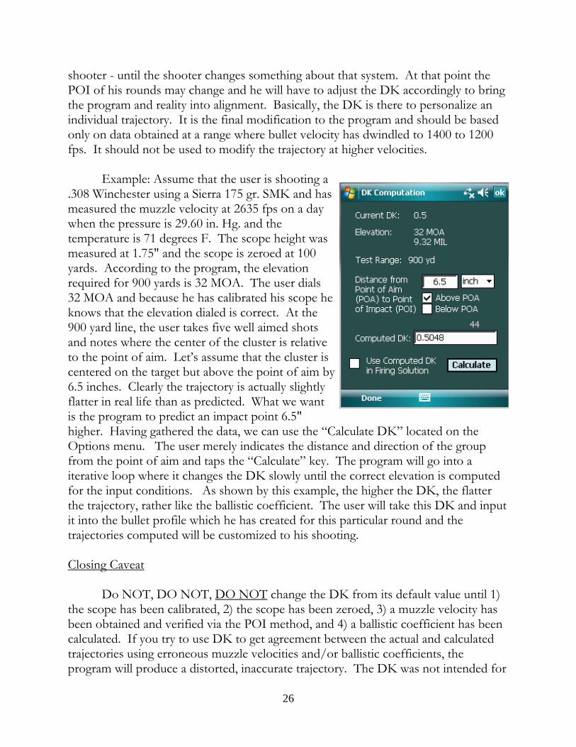
Example: Assume that the user is shooting a.308 Winchester using a Sierra 175 gr. SMK and hasmeasured the muzzle velocity at 2635 fps on a daywhen the pressure is 29.60 in. Hg. and thetemperature is 71 degrees F. The scope height wasmeasured at 1.75" and the scope is zeroed at 100yards. According to the program, the elevationrequired for 900 yards is 32 MOA. The user dials32 MOA and because he has calibrated his scope heknows that the elevation dialed is correct. At the900 yard line, the user takes five well aimed shotsand notes where the center of the cluster is relativeto the point of aim. Let’s assume that the cluster iscentered on the target but above the point of aim by6.5 inches. Clearly the trajectory is actually slightlyflatter in real life than as predicted. What we wantis the program to predict an impact point 6.5"higher. Having gathered the data, we can use the “Calculate DK” located on theOptions menu. The user merely indicates the distance and direction of the groupfrom the point of aim and taps the “Calculate” key. The program will go into aiterative loop where it changes the DK slowly until the correct elevation is computedfor the input conditions. As shown by this example, the higher the DK, the flatterthe trajectory, rather like the ballistic coefficient. The user will take this DK and inputit into the bullet profile which he has created for this particular round and thetrajectories computed will be customized to his shooting.
Closing Caveat
Do NOT, DO NOT, DO NOT change the DK from its default value until 1)the scope has been calibrated, 2) the scope has been zeroed, 3) a muzzle velocity hasbeen obtained and verified via the POI method, and 4) a ballistic coefficient has beencalculated. If you try to use DK to get agreement between the actual and calculatedtrajectories using erroneous muzzle velocities and/or ballistic coefficients, theprogram will produce a distorted, inaccurate trajectory. The DK was not intended for
26
this purpose and will yield completely unusable data. Don’t do it.
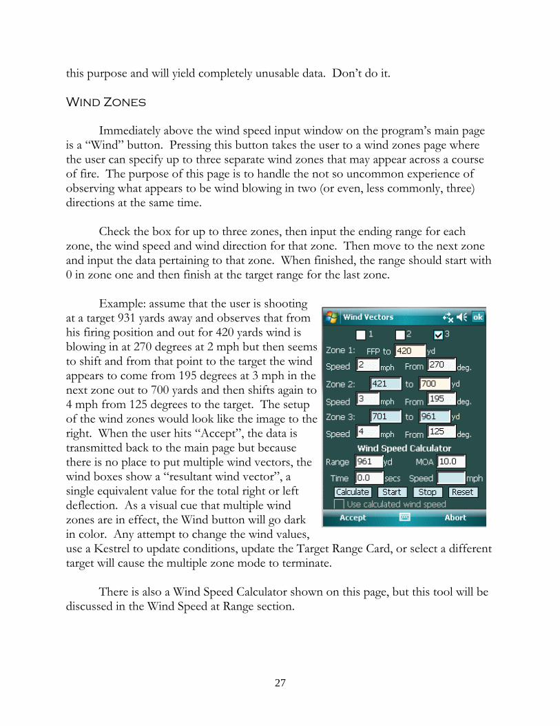
Wind Zones
Immediately above the wind speed input window on the program’s main pageis a “Wind” button. Pressing this button takes the user to a wind zones page wherethe user can specify up to three separate wind zones that may appear across a courseof fire. The purpose of this page is to handle the not so uncommon experience ofobserving what appears to be wind blowing in two (or even, less commonly, three)directions at the same time.
Check the box for up to three zones, then input the ending range for eachzone, the wind speed and wind direction for that zone. Then move to the next zoneand input the data pertaining to that zone. When finished, the range should start with0 in zone one and then finish at the target range for the last zone.
Example: assume that the user is shootingat a target 931 yards away and observes that fromhis firing position and out for 420 yards wind isblowing in at 270 degrees at 2 mph but then seemsto shift and from that point to the target the windappears to come from 195 degrees at 3 mph in thenext zone out to 700 yards and then shifts again to4 mph from 125 degrees to the target. The setupof the wind zones would look like the image to theright. When the user hits “Accept”, the data istransmitted back to the main page but becausethere is no place to put multiple wind vectors, thewind boxes show a “resultant wind vector”, asingle equivalent value for the total right or leftdeflection. As a visual cue that multiple windzones are in effect, the Wind button will go darkin color. Any attempt to change the wind values,use a Kestrel to update conditions, update the Target Range Card, or select a differenttarget will cause the multiple zone mode to terminate.
There is also a Wind Speed Calculator shown on this page, but this tool will bediscussed in the Wind Speed at Range section.
27
Muzzle Velocity from a Chronograph
The chronograph indicates the bullet’s velocity at the location of the measuringunit, not at the muzzle. The military obtains “muzzle velocity” data that is actuallyproduced at 78 feet from the muzzle. It is common for private shooters to measurebullet velocity at 15 to 20 feet from the muzzle. What is clear is that this data reflectsthe bullet’s velocity at some point downrange from the muzzle; the actual muzzlevelocity needs to be derived from this downrange data. The program has a tool tohelp the user in this regard. Choosing Options->Tools->Calculate MV->Chronograph will open a workspace for this purpose and will permit the user tocalculate the actual muzzle velocity of the bullet based upon the chronograph data. The distance to be used is measured from the muzzle to a point midway between thetwo photo-sensors.
The Projectile Metrics Button
To the immediate right of the Range text window on the main page is a smallbutton whose job it is to display various velocity/range related projectile metrics tothe shooter and therefore provide a quick way to see data related to the current range:the height and range of the Maximum Ordinate, the velocity of the projectile and itstotal drop, the energy and momentum of the projectile, the speed of sound, and thetransonic boundaries as well as the maximum supersonic range, the maximum useablerange, and the maximum possible range for the bullet. (The speed of sound is not aconstant value, but changes directly with temperature.) These various data areinformative and can quickly help make a decision whether a given shot has a high,medium or low hit probability.
Visual cues are given to the shooter when the range of any shot is 1) in thetransonic region but still supersonic, 2) in the transonic region but subsonic, and 3)out of the transonic region and subsonic.. In the case of conditions 1 and 2, thebackground color of the Range text window (main program page) changes color asdoes the small subsonic information button, a yellow hue for condition 1, a red huefor condition 2. For conditions where the bullet is not in the transonic region and issubsonic, the window remains a red hue, but the button returns to the normal color.
28
Intermediate Tasks &Tools
29
Intermediate Refinements
Scope Calibration
To use this program effectively, the user must take some time to accuratelyobtain the necessary data used by the program in computing a firing solution. Thefirst important step the user must take is to calibrate his scope. Scope calibrationinvolves measuring the reticle movement over a significant distance at a known rangeand then computing what the click value of the scope really is. This is necessary tocorrectly implement the calculated elevation and windage corrections produced by thesoftware. The problem of an incorrect click value becomes a problem at range andcompromises precision at long and ultra-long ranges.
First: create a chart of some kind, something that is around a foot wide and 72inches high. There is nothing magical about these dimensions; the chart must be wideand high enough to track the reticle movement from the top of the chart down asignificant distance. Make hash marks at regular intervals from top to bottom; thesemarks must thick enough to be visible through the scope at our measurement range. Alternatively, create the same foot wide, 72 inch high target but place 1 inch tapedown the middle from top to bottom and place an aiming point at the very bottom.
Second: place the chart at around 100 yards. The term “around” does notimply that the distance can be approximate, but rather to signify that few ranges havesurveyed distances from bench to target face and as long as the range is “around 100yards or 100 meters” it will do. Place the chart at the target end of the range and takea little time to ensure that it is vertical particularly if you have the tape strip runningdown the middle. Make sure that tape strip is exactly vertical.
Third: back at the shooting bench, set up your rifle. Measure the distancebetween the face of the chart and the turret section of your scope. This distance mustbe very precise, the more precise the better but in no event more than plus/minus onefoot. If the best you can do is plus/minus a yard, you really cannot perform thecalibration because an accurate distance from the reticle to the target face is critical toa precise calculation. The difference between using 100 yards and 101 yards is enoughto change the resulting click value computation. Some people use a steel tape; someuse a laser range finder that can has an accuracy of plus/minus 1 foot; some actuallysurvey the distance, set up markers, and create a permanent calibration space. Whatever method is used, it must provide a distance that is correct within 99.6% ofactual. For purposes of the example here, it is assumed that the range distance is101.5 yards.
30
Forth: make certain that you have zeroed out the parallax in the scope. Parallaxresults when the target image and the reticle image do not fall in the same plane in thescope. Parallax can be detected by getting behind the rifle, looking through the scope,and then moving one’s head up and down, left and right, slightly without disturbingthe rifle. If parallax has been properly eliminated through adjusting the objective lensfocus, the target will not move with respect to the reticle. If parallax is present, theshooter will see movement of one image with respect to the other. Continueadjusting the objective focus until no relative movement is detected. This is importantsince the presence of parallax can provide errors in determining the precise positionwhere the reticle starts and ends on the chart.
Fifth: now measure the distance the reticle travels over the face of the chart. Ifthe rifle being used can clover leaf shots, then start by setting the scope at a 100yard/meter zero and shoot at the bottom aiming dot - just to make sure the rifle iszeroed correctly. Assuming the shots center punch the aiming dot, dial the turret up 3Mils (10 MOA) and fire a couple of shots while insuring your rifle is level with an anti-cant device. Dial up a second 3 Mil (10 MOA) and repeat. Do this until at least onerotation of the elevation has been dialed through, farther if there is additional roomon the chart. When finished, if the scope has been mounted vertically, all the roundsshould march straight up the tape.
Or forego shooting this process and use the chart itself to measure the amountof reticle travel. Place the rifle in some sort of firmly held vice or sand baggedposition where dialing the scope will not disturb the rifle itself. Dial to the scope’szero or close thereto and place the horizontal reticle element right on the top hashmark on the chart. Make note of the turret setting. Then begin to dial the turret up 3Mils (10 MOA) at a time. You will see the reticle move downward in the scope as youdo this. At each interval, note where on the chart the reticle is. Be precise with this;these distances are going to measured with a tape measure to the nearest 1/8th of aninch after all data has been gathered. Be as careful and as precise as possible.
Sixth: at this point, the data gathering is done. Bring the chart back to theshooting bench and for those that measured the reticle movement on the chart, take atape measure and measure the distances from the top of the chart to each interval. Make pencil hash marks for each place the reticle landed as you moved through eachinterval and note not only the total increasing distance each point was from thebeginning point, but make note of the distance between each interval. If the turret isuniform in its click value, then the distances between each interval will be the sameover the whole distance measured. Record the total distance covered from the top ofthe chart to the last hash mark on the chart.
31
For those who shot the chart, do the same measurements and record thedistance from the bottom aiming point to each group and measure the distancesbetween each group.
Seventh: calculate the click value based upon the actual reticle movementacross the face of the chart. There are three inputs: 1) the precise range from turretto chart face (range); 2) the distance from the top (or bottom) of the chart to the lasthash mark (or bullet group) at the bottom (or top) (this we will call the “chartdistance”); and, the number of turret clicks it took to cover the chart distance (clicks). These values are input in the software at Options->Tools->Scope Calibration. Thiswork area will precisely calculate the actual click value for the scope being measured.
Calculating Muzzle Velocity by the POI Method
After obtaining the muzzle velocity of any given cartridge by using achronograph, it is essential to check the data by confirming the trajectory at a rangebetween 300 and 600 meters using the shorter range for small calibers and the longerranges for large calibers. The program has a tool to help the user in this regard. Choosing Options->Calculate MV->POI Method will open a workspace designed tocorrelate the point of impact on the target with a muzzle velocity. The user may askwhy this step is necessary given the fact that the muzzle velocity has been measureddirectly by a highly precise piece of equipment. “Highly precise” doesn’t necessarilymean “accurate.” A chronograph is not self-calibrating and there is no way for mostshooters to determine whether his chronograph is outputting accurate numbers. Using the POI method to determine muzzle velocity is a good way to check thechronograph and these checks may show that the user’s chronograph is habituallygiving results above or below the actual muzzle velocity.
The tool can also be used to determine the muzzle velocity of cartridges wherea chronograph is not available. Essentially, the user must have knowledge of thebullet used in the cartridge and its ballistic coefficient, weight, and have a publishedmuzzle velocity value so that the Presets page can be filled in. Set a target asdescribed above and set the elevation as calculated by the program. Assuming thatthe weight and BC are reasonably correct, any deviation from the trajectory will resultpredominantly from an incorrect muzzle velocity. Input the distance above or belowthe point of aim that the bullet strikes the target and the program will calculate theactual muzzle velocity necessary to have placed the bullet where it did. Update thebullet profile with this velocity and ambient temperature.
32
Calculating a Bullet’s Ballistic Coefficient
The primary bullet attributes that influence a trajectory is bullet velocity and therate at which the air slows the bullet during flight, i.e., how much drag the projectileexperiences. This tool, found at Options->Tools->Calculate BC enables a user torefine the G1 ballistic coefficient of the bullet as published by the manufacturer and tocompute a BC that will produce optimum results in the program.
Using a ChronographThis workspace is quite simple: the user will obtain two velocities using a
chronograph, the first at or near the muzzle depending upon the chronograph used. The second velocity is obtained at some down range location where the user cansafely and reliable still shoot over his chronograph without hitting it. He then takes acareful measurement of the distance between the muzzle and the mid-point of thechronograph at each location, subtracts the two to get the range over which the bullethas slowed, and using this range and the two velocities obtained can calculate thebullet’s BC. This BC can be used for this bullet in all applications, ranges, andweather conditions and should be permanently recorded in the bullet’s profile.
POI MethodThis workspace uses the impact point of the bullet to determine its ballistic
coefficient. There are some assumptions at work to do this: first, it is assumed thatthe shooter has obtained a good and accurate zero. Second, it is assumed that theshooter has obtained an accurate muzzle velocity. If these assumptions are groundedin fact, then it is likely that at range what error is noted between the calculatedelevation and the actual elevation is due to an errant ballistic coefficient. The term “atrange” as used here means a range sufficient for the trajectory to develop and beaffected by the ballistic coefficient of the bullet but not so far as to allow other forcesand effects to alter the trajectory. For purposes of the program, the requisite range isactually based upon the velocity of the bullet. A desirable velocity range would beabove the speed of sound but far enough for the bullet to have slowed substantially,somewhere between 1350 fps and 1650 fps (410 m/s and 500 m/s.)6 This methodavoids the drawbacks inherent in the chronograph method of obtaining muzzle anddownrange velocities but suffers from the assumption that any deviation betweenpoint of aim and point of impact is due to the usage of an incorrect ballisticcoefficient. Therefore, the shooter must be alert to other possible causes which may
6 The lower velocity is just above the start of the transonic region and guarantees thatevery bullet used in long range shooting will be stable at this point. This velocity can be loweredto just above the supersonic velocity if the bullet being used is known stable into the transonicregion.
33
be responsible for or at least contribute to this difference, such as up or down drafts,fluctuating or errant muzzle velocity, poor understanding of the actual range involved,cross-wind vertical deflection, mirage and its effect on target acquisition. The shootermust evaluate conditions, distances, and the accuracy of his input data in order forhim to have confidence in the resulting ballistic coefficient calculation. If everythinggoing in is good data, the result should be a good, dependable and useable BC value.
Comparison of the Two MethodsThe best method is to use the muzzle velocity and downrange velocity of a
single bullet. However, obtaining this kind of data tends to be expensive. Either theshooter must obtain Doppler data (which is excellent for BC analysis) or invest inexpensive equipment such that the velocity of the same bullet can be measured atboth the muzzle and at some significant downrange location.
Since generally most shooters do not have access to either Doppler data nor asetup which would provide muzzle and downrange velocities of the same bullet, he isleft with measuring the muzzle velocity first (generally with a chronograph) and thenmoving the chronograph to a location downrange and obtaining a velocity from asecond bullet there. However, for each bullet sent over the chronograph at range, it isnot known what the muzzle velocity of that particular bullet is. The shooter is leftwith performing the BC analysis with an average muzzle velocity, an averagedownrange velocity, leading to an average BC. All in all, this is an unsatisfactoryapproach but is better then nothing.
Slightly improved is the POI method. At least the shooter is dealing with thesame bullet from muzzle to target. The drawbacks are that at increasing range thenumber of extraneous effects can multiply and have an effect upon trajectory. Nevertheless, if the shooter can place a single bullet on a distant target with a highdegree of confidence that the round was well aimed and landed properly without theintrusion of errant wind swirls, bullet wobbles, or the myriad of other effects that candistort a trajectory, then that single bullet point of impact can be used to calculate adecent ballistic coefficient. So, like so many things in long range shooting, it takessome skill and reasonably good sense to evaluate conditions, the shot, and the results. But potentially this approach represents an efficient and effective means of calculatinga ballistic coefficient that makes sense for use in this software.
Getting and Using Magnetic Bearing
Obtaining bearings to a target can be done via a map, in which case truebearings can be used. But in the field getting a target bearing is generallyaccomplished with a compass in which case the user will be gathering data in terms of
34
a magnetic bearing. Therefore, the program needs to handle both true bearings (mapbearings) and magnetic bearings (compass bearings) with equal ease. This also meansthat a way to obtain the magnetic variation of a particular location is required. Magnetic variation is not constant across the entire globe but varies by locale and infact changes over time. The software uses a database created by the NationalGeospatial-Intelligence Agency for its World Magnetic Model to calculate magneticvariation for any place on Earth.
The program needs to know where it is or at least what location the computedfiring solutions relate to. One way to tell the program its current location is to createlocation files in the Map Ranging form and then loading the appropriate file. Anotheris to obtain the current location via a GPS device and to save the location it provides. Or, in the Map form, enter that data as a FFP and Accept that data. (In this lattermethod, when a new FFP is loaded, the old will be lost.)
For purposes of this explanation of how to use magnetic variation in theprogram, the assumption is that you have a location file or otherwise know how toinput a location (this will be explored in detail in the GPS and Map Ranging sectionsbelow.) Once a location is input, tap the “CV” button on the main form in the upperright hand corner. In this case “CV” means “Coriolis/Variation” and represents theaccess point to input the data needed to compute Coriolis acceleration. On theCoriolis page you will see that only the Latitude window is available for location. While only latitude is needed for Coriolis computation, to compute the magneticvariation both latitude, longitude and altitude is required. At the bottom of the CVpage is menu item “Compute” which takes the user to a page where the requiredlocation parameters can be input. If a GPS is connected and running in thebackground, the GPS menu item will be active and pressing it will cause the currentlocation parameters as reported by the GPS to be imported into the data textwindows. Once this data importation is complete, the program will automaticallycompute the magnetic variation for that location. If the user wishes to use that data,he clicks “Accept” and will exit back to the CV page. Here he will see that the latitudefor Coriolis purposes has been updated to the current location and that the magneticvariation has been brought in from the previous page. He can now opt to use Corioliscomputations by clicking the box and opt to use the magnetic variation value bychecking that box. At that point, the user must “Accept” his elections and exit or“Abort” what he has done.
If he has chosen to use Coriolis computations in the firing solutions, theBearing text box on the main page, which was yellow, is now white. This is a visualcue as to whether Coriolis is being used or not. Also, below the “Bearing” label thereis an indication that the Bearing is “Magnetic” meaning that magnetic variation is
35
being used and the bearing figure is a compass bearing. On the other hand,unchecking the Magnetic Variation box on the CV form will cause the Bearing to be“True”, i.e., the bearing as shown on a map.
Magnetic variation can also be selected as an option in the Options menu list. If it appears that no actual location has been input, choosing magnetic variation willresult in an advisory that “Magnetic Variation equals zero” which generally means thatthe program is using a default value and that a magnetic variation has not beencomputed. Choosing to activate Coriolis in the absence of a current location willprompt an advisory that “A current position has not been selected.” Looking at themain page will show “None” and the Presets page will show all zeros for current FFP, a sure sign that no current position has been input. The user is encouraged to let theprogram know where on earth the calculations relate to. The program can do manyother things if it knows the location of the firing position.
36
Target Ranging
A. Direct Ranging
Opening the Direct Ranging page allows the user to manually input a range,bearing and angle and then save the file for later use on the Targets list. These arethe target files that will appear when “Direct Range” is selected as the FFP.
B. Map Ranging
The purpose of the Map Ranging page is to input firing positions (FFPs) andtarget locations in the form of location coordinates for saving and use on the Targetslist and Target Card. FFP location can be obtained one of two ways: 1) from a map;2) from a GPS. In the first case, it is necessary to input either Lat/Lon coordinates,UTM or MGRS coordinates and an altitude manually and then save the files to somemeaningful name. In the second case, the user can get the coordinates directly from aGPS running in the background. It is possible to connect a GPS to the PDA, open aserial port and leave it running in the background so that various parts of the programcan have access to the location data it provides. In the map ranging page, when aGPS is running in the background the GPS menu item becomes active and pressing itcauses the current GPS coordinates and altitude to be inserted in the proper data textwindows. At this point the location can be saved to a file. These files will show up onthe FFP drop down list on the Targets page.
There are buttons associated with the FFP and Target labels. By default theFFP button is active so clicking the GPS menu item will cause the data for the FFP tofill. However, if the user wants to channel the data to the target data areas, just clickthe Target label and the Target data windows become the location for the GPS data. Once the data is obtained, just save the Target file. These files will show up listed inthe target area on the Targets page form.
Target coordinates can be obtained a third way. These parameters can beentered by hand or by opening an existing Direct target file which contain just therange, bearing and angle of a target. If a current location is listed in the FFP sectionand the user has the range, bearing and shot angle to a target, he can check the“TargetCoordinates” box, input the data and press the Calculate button. The program willuse the range, bearing and angle information to calculate the coordinates of the targetlocation relative to the current FFP. In this way, once an FFP has been established,the user can survey the area and use his rangefinder to range various likely targetlocations. If the rangefinder is attached to the PDA, each ranging will input the range,azimuth and angle of the target. The program will then calculate the coordinates of
37
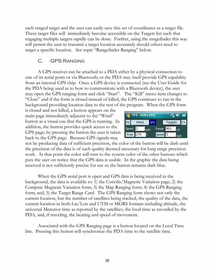
each ranged target and the user can easily save this set of coordinates as a target file. These target files will immediately become accessible on the Targets list such thatengaging multiple targets rapidly can be done. Further, using the rangefinder this waywill permit the user to transmit a target location accurately should others need totarget a specific location. See topic “Rangefinder Ranging” below.
C. GPS Ranging
A GPS receiver can be attached to a PDA either by a physical connection toone of its serial ports or via Bluetooth; or the PDA may itself provide GPS capabilityfrom an internal GPS chip. Once a GPS device is connected (see the User Guide forthe PDA being used as to how to communicate with a Bluetooth device), the usermay open the GPS ranging form and click “Start”. The “Kill” menu item changes to“Close” and if the form is closed instead of killed, the GPS continues to run in thebackground providing location data to the rest of the program. When the GPS formis closed and not killed, a button appears on themain page immediately adjacent to the “Wind”button as a visual cue that the GPS is running. Inaddition, the button provides quick access to theGPS page; by pressing the button the user is takenback to the GPS page. Because GPS signals maynot be producing data of sufficient precision, the color of the button will be dark untilthe precision of the data is of such quality deemed necessary for long range precisionwork. At that point the color will turn to the system color of the other buttons whichputs the user on notice that the GPS data is usable. In the graphic the data beingreceived is not sufficiently precise for use so the button remains dark blue.
When the GPS serial port is open and GPS data is being received in thebackground, the data is available to: 1) the Coriolis/Magnetic Variation page; 2) theCompute Magnetic Variation form; 3) the Map Ranging form; 4) the GPS Rangingform; and, 5) the Target Range Card. The GPS Ranging form shows not only thecurrent location, but the number of satellites being tracked, the quality of the data, thecurrent location in both Lat/Lon and UTM or MGRS formats including altitude, theuniversal Mercator time as reported by the satellites, the local time as recorded by thePDA, and, if traveling, the bearing and speed of movement.
Associated with the GPS Ranging page is a button located on the Local Timeline. Pressing this button will synchronize the PDA time to the satellite time.
38
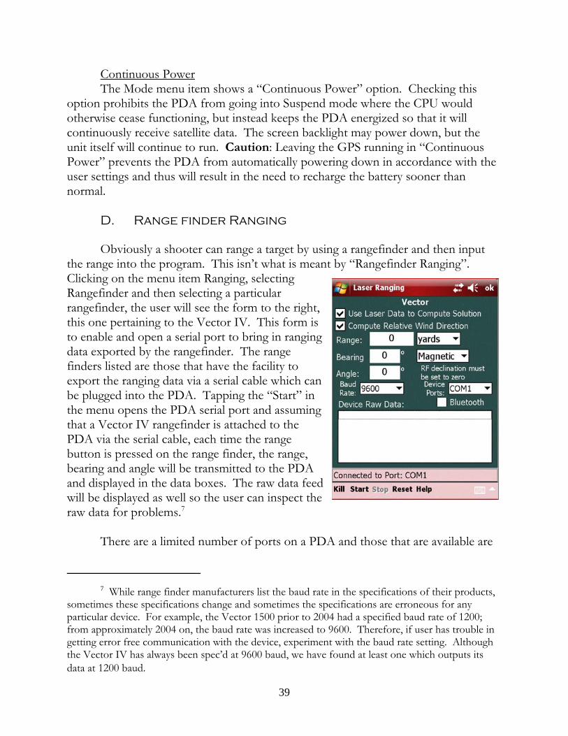
Continuous PowerThe Mode menu item shows a “Continuous Power” option. Checking this
option prohibits the PDA from going into Suspend mode where the CPU wouldotherwise cease functioning, but instead keeps the PDA energized so that it willcontinuously receive satellite data. The screen backlight may power down, but theunit itself will continue to run. Caution: Leaving the GPS running in “ContinuousPower” prevents the PDA from automatically powering down in accordance with theuser settings and thus will result in the need to recharge the battery sooner thannormal.
D. Range finder Ranging
Obviously a shooter can range a target by using a rangefinder and then inputthe range into the program. This isn’t what is meant by “Rangefinder Ranging”. Clicking on the menu item Ranging, selectingRangefinder and then selecting a particularrangefinder, the user will see the form to the right,this one pertaining to the Vector IV. This form isto enable and open a serial port to bring in rangingdata exported by the rangefinder. The rangefinders listed are those that have the facility toexport the ranging data via a serial cable which canbe plugged into the PDA. Tapping the “Start” inthe menu opens the PDA serial port and assumingthat a Vector IV rangefinder is attached to thePDA via the serial cable, each time the rangebutton is pressed on the range finder, the range,bearing and angle will be transmitted to the PDAand displayed in the data boxes. The raw data feedwill be displayed as well so the user can inspect theraw data for problems.7
There are a limited number of ports on a PDA and those that are available are
7 While range finder manufacturers list the baud rate in the specifications of their products,sometimes these specifications change and sometimes the specifications are erroneous for anyparticular device. For example, the Vector 1500 prior to 2004 had a specified baud rate of 1200;from approximately 2004 on, the baud rate was increased to 9600. Therefore, if user has trouble ingetting error free communication with the device, experiment with the baud rate setting. Althoughthe Vector IV has always been spec’d at 9600 baud, we have found at least one which outputs itsdata at 1200 baud.
39
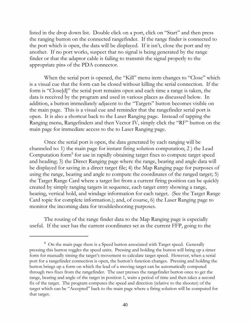
listed in the drop down list. Double click on a port, click on “Start” and then pressthe ranging button on the connected rangefinder. If the range finder is connected tothe port which is open, the data will be displayed. If it isn’t, close the port and tryanother. If no port works, suspect that no signal is being generated by the rangefinder or that the adaptor cable is failing to transmit the signal properly to theappropriate pins of the PDA connector.
When the serial port is opened, the “Kill” menu item changes to “Close” whichis a visual cue that the form can be closed without killing the serial connection. If theform is “Close[d]” the serial port remains open and each time a range is taken, thedata is received by the program and used in various places as discussed below. Inaddition, a button immediately adjacent to the “Targets” button becomes visible onthe main page. This is a visual cue and reminder that the rangefinder serial port isopen. It is also a shortcut back to the Laser Ranging page. Instead of tapping theRanging menu, Rangefinders and then Vector IV, simply click the “RF” button on themain page for immediate access to the to Laser Ranging page.
Once the serial port is open, the data generated by each ranging will bechanneled to: 1) the main page for instant firing solution computation; 2 ) the LeadComputation form8 for use in rapidly obtaining target fixes to compute target speedand heading; 3) the Direct Ranging page where the range, bearing and angle data willbe displayed for saving in a direct target file; 4) the Map Ranging page for purposes ofusing the range, bearing and angle to compute the coordinates of the ranged target; 5)the Target Range Card where a target list from a current firing position can be quicklycreated by simply ranging targets in sequence, each target entry showing a range,bearing, vertical hold, and windage information for each target. (See the Target RangeCard topic for complete information.); and, of course, 6) the Laser Ranging page tomonitor the incoming data for troubleshooting purposes.
The routing of the range finder data to the Map Ranging page is especiallyuseful. If the user has the current coordinates set as the current FFP, going to the
8 On the main page there is a Speed button associated with Target speed. Generallypressing this button toggles the speed units. Pressing and holding the button will bring up a timerform for manually timing the target’s movement to calculate target speed. However, when a serialport for a rangefinder connection is open, the button’s function changes. Pressing and holding thebutton brings up a form on which the lead of a moving target can be automatically computedthrough two fixes from the rangefinder. The user presses the rangefinder button once to get therange, bearing and angle of the target in position 1, waits a period of time and then takes a secondfix of the target. The program computes the speed and direction (relative to the shooter) of thetarget which can be “Accepted” back to the main page where a firing solution will be computed forthat target.
40
Map Ranging page will fill the FFP location with the current data. Ranging a targetwith a connected rangefinder will fill in the Range, Bearing and Angle windows on theform. Checking the Target Coordinates box will cause the Calculate button tocalculate the target’s coordinates based upon the current location and the ranging data. The user can then quickly save the target coordinates in a target file for later use onthe Targets List.
On the Target Ranging Card the data is handled similarly. If the FFP is set,each ranging causes the automatic calculation of the target’s coordinates and uponsaving the target group, each file is saved as a Position target file and is included in atarget group file for quick loading later.
Use Laser Data to Compute SolutionBy default when the program starts, this check box is checked and each time
the range finder ranges a target as solution is computed. However, when rangingtargets that are beyond the practical range of the rifle or when the objective is merelyto range targets for purposes other than engaging with the rifle, this box may be un-checked in which case the range finder data is still distributed throughout theprogram, but no solution calculated. In addition, when the this box is unchecked the“RF” button on the main page turns a dark blue as a visual cue that firing solutionsare not being computed. As an additional reminder the solutions windows show only“----” instead of a numeric value. Therefore, when using the program to plot targetlocations on the Map Ranging page, uncheck the box, open the laser port, close theLaser Ranging page and open the Map Ranging page. With the “Compute TargetCoordinates” box checked and a current FFP location, each ranging will automaticallycalculate the ranged target’s coordinates.
Compute Relative Wind DirectionThe range finder interface page has a check box labeled “Compute Relative
Wind Direction” which is selected by default. When selected, the user will see thewind direction on the main page change as targets are lased in order to reflect anaccurate relative wind direction for each lased target given its particular bearing. Unchecking the box will cause the windage direction to remain constant during targetranging.
Limited Function RangefindersThe PLRF rangefinder, as an example, does not have an internal compass or
inclinometer and thus does not output a bearing to the target or a target angle. Thereare other rangefinder brands of similar limited functionality. Upon selecting suchrangefinder, the data inputs which cannot be supplied by the rangefinder will begrayed out on the interface page and these values must then be input by hand.
41
E. Reticle Ranging
This form calculates the range based upon the height of the target, the size ofthe target as seen in the scope and measured in Mils or MOA.9 The resultingcomputed range can either be “Accept[ed]” and imported back to the main page forcomputation of the firing solution or “Abort[ed]”.
Next to the Target data window is a button which brings up a Size of Objectseditor. This editor permits the reading of lists containing the known size of variousobjects which may be encountered in the file. The editor also permits the editing ofexisting lists and the creation of new lists.
Editing an Existing List - make the required changes or additions and thenpress the “Save” menu item. All changes are saved to the existing file.
Making a New List - make changes to an existing list and then click on the“SaveAs” menu item. A file naming text window appears at the top of the screen. Tap <Enter> to save the file. (Tapping <Enter> on an empty screen aborts theprocess.) To create a brand new list, click on “New” and add the desired data. Thenfinish with “SaveAs” and enter the name of the file. Upon the creation of the newlist, the drop down menu is updated and the new file will immediately appear on thelist.
Getting Size Data - the user can import a size number back to the ReticleRanging form by 1) highlighting the desired number and 2) clicking “Close”. At thatpoint the Size Lists form closes and the selected number appears in the Target sizewindow. The user must then ensure that the units (inches, feet, yards, centimeters, ormeters) for the imported value are correct. Only the number may be highlighted; donot include any additional text such as units.
9 The form can also be used as a training aid in that it allows input of any twounknowns for calculation of the third. Thus a target of known size and at a knowndistance can be input so the shooter can see what the target of the calculated Mil sizelooks like in the scope.
42
Intermediate Profiles
A. The Offset Profile
The offset profile is linked to a particular rifle, a default cartridge, and its owncartridge list similar to the rifle profile. The cartridges listed in the offset profile neednot be the same cartridges associated with the rifle profile. This is a powerful featurewhich provides a method to compensate for a shift in bullet point of impact due to 1)a change of ammunition; 2) a change of shooting position or rifle configuration (suchas adding or removing a suppressor); or, 3) a change of shooter. In fact, any change inthe rifle, scope, cartridge, or shooter that causes a point of impact (POI) shift can becorrected by use of an offset profile. When a modification that changes the POIoccurs, there are only three basic ways of dealing with it: 1) make a mental note tohold for the change; 2) when dialing elevation and windage, adjust the numbers forthe offset and dial the adjusted numbers; or, 3) re-zero the scope. The Offset Profileeffectively implements option number 2. By indicating what the offset is and how tobring the new point of impact back to the point of aim, the user has provided theprogram with sufficient data to “correct” the elevation and windage solutions suchthat the round will strike where the shooter is aiming without having to adjust thescope. The offset profile may have the same or different cartridges listed than thoselisted in the related rifle profile. This design decision was implemented to give themost flexibility to the user.
The implication of the offset profile is that each user should have his ownoffset profile for each rifle he shoots in each position if a change of position causeschanges in POI. Further, it is a good idea to name these files in some descriptive wayso that when accessing the file the user can tell what the file relates to just by lookingat the file name. There are many ways to do this and the user is encouraged to devisehis own comprehensive file naming protocol. A possible approach is set forth in theAppendix.
To use the offset profile, enter the initials or other description, a team ifapplicable, and mode. Note that the mode comes with a list of possible descriptors asa convenience, but the user can simply type in his own as necessary; same with theTeam list. Add any offset notes.
Next, browse for a rifle that this offset will relate to. When selecting a rifle,whatever bullet is the default bullet for the rifle profile will also be initially listed as thedefault bullet for the offset file. Note the “Add” item in the menu. This is a contextsensitive item: when pressed on the main page it means “add cartridges to a list” andwill call the cartridge list shown below. When pressed on the cartridge list form, it will
43
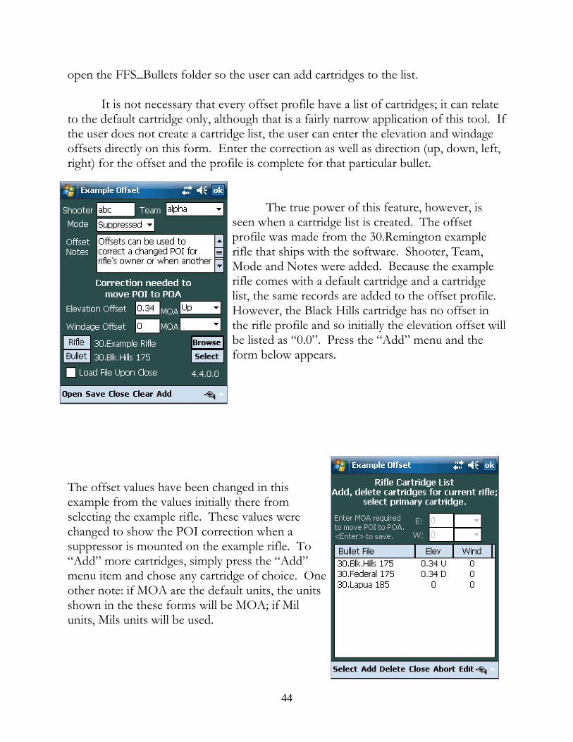
open the FFS_Bullets folder so the user can add cartridges to the list.
It is not necessary that every offset profile have a list of cartridges; it can relateto the default cartridge only, although that is a fairly narrow application of this tool. Ifthe user does not create a cartridge list, the user can enter the elevation and windageoffsets directly on this form. Enter the correction as well as direction (up, down, left,right) for the offset and the profile is complete for that particular bullet.
The true power of this feature, however, isseen when a cartridge list is created. The offsetprofile was made from the 30.Remington examplerifle that ships with the software. Shooter, Team,Mode and Notes were added. Because the examplerifle comes with a default cartridge and a cartridgelist, the same records are added to the offset profile. However, the Black Hills cartridge has no offset inthe rifle profile and so initially the elevation offset willbe listed as “0.0”. Press the “Add” menu and theform below appears.
The offset values have been changed in thisexample from the values initially there fromselecting the example rifle. These values werechanged to show the POI correction when asuppressor is mounted on the example rifle. To“Add” more cartridges, simply press the “Add”menu item and chose any cartridge of choice. Oneother note: if MOA are the default units, the unitsshown in the these forms will be MOA; if Milunits, Mils units will be used.
44
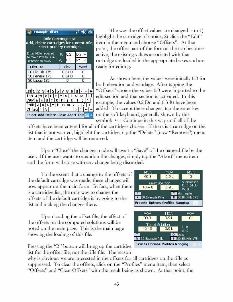
The way the offset values are changed is to 1)highlight the cartridge of choice; 2) click the “Edit”item in the menu and choose “Offsets”. At thatpoint, the offset part of the form at the top becomesactive, the existing values associated with thatcartridge are loaded in the appropriate boxes and areready for editing.
As shown here, the values were initially 0.0 forboth elevation and windage. After tapping the“Offsets” choice the values 0.0 were imported to theedit section and that section is activated. In thisexample, the values 0.2 Dn and 0.3 Rt have beenadded. To accept these changes, tap the enter keyon the soft keyboard, generally shown by thissymbol: 5 . Continue in this way until all of the
offsets have been entered for all of the cartridges chosen. If there is a cartridge on thelist that is not wanted, highlight the cartridge, tap the “Delete” (now “Remove”) menuitem and the cartridge will be removed.
Upon “Close” the changes made will await a “Save” of the changed file by theuser. If the user wants to abandon the changes, simply tap the “Abort” menu itemand the form will close with any change being discarded.
To the extent that a change to the offsets ofthe default cartridge was made, these changes willnow appear on the main form. In fact, when thereis a cartridge list, the only way to change theoffsets of the default cartridge is by going to thelist and making the changes there.
Upon loading the offset file, the effect ofthe offsets on the computed solutions will benoted on the main page. This is the main pageshowing the loading of this file.
Pressing the “B” button will bring up the cartridgelist for the offset file, not the rifle file. The reasonwhy is obvious: we are interested in the offsets for all cartridges on the rifle assuppressed. To clear the offsets, click on the “Profiles” menu item, then select“Offsets” and “Clear Offsets” with the result being as shown. At that point, the
45
cartridge list returns to the list associated with the rifle profile, in this case the“30.Example Rifle”. (You will see the change in the MOA solution although theturret solution remains unchanged. This is a function of the turret itself which, in thiscase, is a 1 MOA/click turret so in this case the turret solution is the same. This willnot be the case for either 0.1 Mil/click or 1/4 MOA/click scopes.) Or, a moreefficient way to clear the offset is to tap the “O” button, tap and hold on the loadedoffset file and choose “Clear” on the resulting context menu.
The offsets concept is flexible and applicable to a variety of problems. It isanticipated that this feature can be adapted to many, many issues that lead to aconsistent change in POI. The offset profile may offer a solution for those issues.
B. Saving a Complete Solution
Although the Solution item is listed in the profile menu, it technically isn’t aprofile at all. Basically saving a solution means to save the entire setup as it thenexists. The program does this automatically each and every time the program exits. This is how the program can start from where the user left off in a previous session. When the program starts it looks for a file called “eSession”, opens the file and loadsthe data saved from the previous session. The only time when there is no eSessionfile is the very first time the program starts.
The value of saving a complete data set is limited. It is helpful if an area wherethe user generally shoots has a fairly consistent weather pattern and the user shootsthe same rifle system. It is also helpful if the user wants to save a particular setup forfurther analysis at some later time.
C. Targeting Profiles
Targeting profiles are simply FFP, Position Target and Direct Target files. TheFFP and Position Target Profiles have similar data as the Map Ranging form and thefiles are interchangeable, the difference being that the profile form allows for the entryof notes and comments. Thus, the FFP and Position Target Profiles can have moreextensive data associated with them than a similar file created in the Map Ranging file. Both files, however, can be brought up and read in either form. The Direct TargetProfile takes the user to a form very similar to the Direct Target Ranging form andidentical in content. And, as with all profiles, after creating a Targeting Profile, theuser can elect to save the data and/or load the data into the program upon closing theform (“Accept”) or abandon the data with or without saving it first.
46
Quick Access Data Buttons
In order to manage teams of shooters or multiple firearms, quick access torelevant data files is desirable not only to load a particular file but to inspect or editthese files in a summary fashion. To facilitate this access, keys or buttons are locatedon the main page at the bottom which take the user immediately to lists of offsets,rifles, the bullet database and the target list. The other buttons list the current datarelated to the currently loaded data file(s). Thus, if an offset file is loaded and iscurrent, the shooters identity, the shooting position, and the elevation and windageoffset is shown on the main page in order to apprise the team leader of all pertinentdata. The rifle button lists the current rifle; the bullet button lists the current bullet;and, as mentioned, the target button list the current target.
A. Offsets List
The program supposes that in a rifle team there will be a number of offset filesfor team members shooting their own rifles with various cartridges and teammembers shooting other members rifles. Pressing the “O” button produces a list ofoffset profiles which can be filtered by shooter and team. Each offset file lists the filename and the rifle which it links to. As with all lists, highlighting any particular fileallows use of the “Edit” menu item. Tap the edit item or press the far right hardwarekey and the highlighted file will be opened in a edit form such that the data can bemodified or inspected. Tapping the far left button closes the edit form and brings theuser back to the list.
When the offset button is first pressed, the list is automatically filtered for therifle currently in use. Thus the list shows all offset files that pertain to that particulartype of rifle. To see more offset files, press the “All Rifles” button at the bottom ofthe form.
B. Rifles List
When the Rifle List button is pressed, all rifle profiles are shown whether therifle files are linked to offset files or not. At the top of the list are filters that will filterthe list of rifles by individual shooter and/or team. If the team leader wants to seewhat rifles are available in any particular team, he simply looks at the team drop downlist and selects the team of interest. The team names are taken from the offset files, soclearly each shooter and his rifle should be represented by an offset file even if the fileshows no offsets. Note also that when the rifles are filtered by any criteria each offsetfile is read and the data, including the position, is placed on the list. This data helps
47
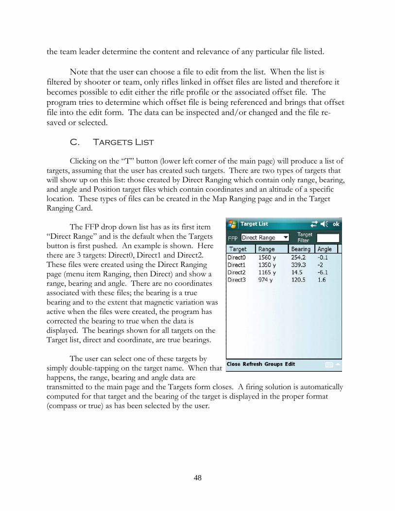
the team leader determine the content and relevance of any particular file listed.
Note that the user can choose a file to edit from the list. When the list isfiltered by shooter or team, only rifles linked in offset files are listed and therefore itbecomes possible to edit either the rifle profile or the associated offset file. Theprogram tries to determine which offset file is being referenced and brings that offsetfile into the edit form. The data can be inspected and/or changed and the file re-saved or selected.
C. Targets List
Clicking on the “T” button (lower left corner of the main page) will produce a list oftargets, assuming that the user has created such targets. There are two types of targets thatwill show up on this list: those created by Direct Ranging which contain only range, bearing,and angle and Position target files which contain coordinates and an altitude of a specificlocation. These types of files can be created in the Map Ranging page and in the TargetRanging Card.
The FFP drop down list has as its first item“Direct Range” and is the default when the Targetsbutton is first pushed. An example is shown. Herethere are 3 targets: Direct0, Direct1 and Direct2. These files were created using the Direct Rangingpage (menu item Ranging, then Direct) and show arange, bearing and angle. There are no coordinatesassociated with these files; the bearing is a truebearing and to the extent that magnetic variation wasactive when the files were created, the program hascorrected the bearing to true when the data isdisplayed. The bearings shown for all targets on theTarget list, direct and coordinate, are true bearings.
The user can select one of these targets bysimply double-tapping on the target name. When thathappens, the range, bearing and angle data aretransmitted to the main page and the Targets form closes. A firing solution is automaticallycomputed for that target and the bearing of the target is displayed in the proper format(compass or true) as has been selected by the user.
48
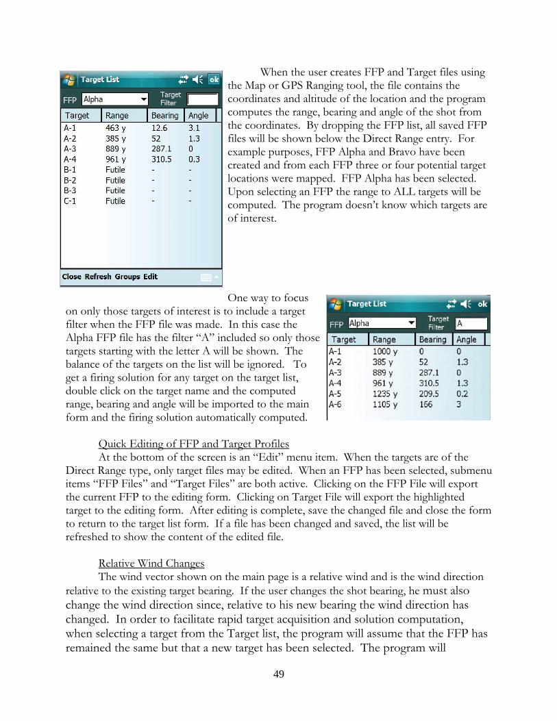
When the user creates FFP and Target files usingthe Map or GPS Ranging tool, the file contains thecoordinates and altitude of the location and the programcomputes the range, bearing and angle of the shot fromthe coordinates. By dropping the FFP list, all saved FFPfiles will be shown below the Direct Range entry. Forexample purposes, FFP Alpha and Bravo have beencreated and from each FFP three or four potential targetlocations were mapped. FFP Alpha has been selected. Upon selecting an FFP the range to ALL targets will becomputed. The program doesn’t know which targets areof interest.
One way to focuson only those targets of interest is to include a targetfilter when the FFP file was made. In this case theAlpha FFP file has the filter “A” included so only thosetargets starting with the letter A will be shown. Thebalance of the targets on the list will be ignored. Toget a firing solution for any target on the target list,double click on the target name and the computedrange, bearing and angle will be imported to the mainform and the firing solution automatically computed.
Quick Editing of FFP and Target ProfilesAt the bottom of the screen is an “Edit” menu item. When the targets are of the
Direct Range type, only target files may be edited. When an FFP has been selected, submenuitems “FFP Files” and “Target Files” are both active. Clicking on the FFP File will exportthe current FFP to the editing form. Clicking on Target File will export the highlightedtarget to the editing form. After editing is complete, save the changed file and close the formto return to the target list form. If a file has been changed and saved, the list will berefreshed to show the content of the edited file.
Relative Wind ChangesThe wind vector shown on the main page is a relative wind and is the wind direction
relative to the existing target bearing. If the user changes the shot bearing, he must alsochange the wind direction since, relative to his new bearing the wind direction haschanged. In order to facilitate rapid target acquisition and solution computation,when selecting a target from the Target list, the program will assume that the FFP hasremained the same but that a new target has been selected. The program will
49
recompute the relative wind for the new target bearing and then compute a firingsolution using this new relative wind direction. Locations loaded into the programother than from the Target list will not affect the wind direction on the main page.
Exiting the ListThis form does not have an “Accept”, “Abort” or “Done” menu item. Exit by
tapping the “Close” in the menu or by tapping “OK” at the top of the form.
D. Bullet Files
The bullets button at the bottom of the main page produces all cartridges thatthe user has associated with the rifle or offset profile currently selected and inmemory. This is a particularly powerful feature of the software since the two listsneed not be the same. An interesting application for having two distinct list is the riflethat is suppressed enabled. Without a suppressor, the rifle will perform one way witha particular cartridge acting as the default cartridge for purposes of the scope’s zeroand a list of other cartridges that may be chosen along with their respective elevationand windage offsets. Upon mounting the suppressor, two common things happen: 1)there may be a shift in point of impact for all cartridges; and, 2) there may be a muzzlevelocity change for each cartridge. The solution would be to create two sets of bulletprofiles for this rifle, unsuppressed and suppressed, with the relevant muzzle velocity,temperatures, etc., for each. Assume that the normal mode of operation isunsuppressed. In that case the unsuppressed set of cartridges will be placed in therifle’s profile; the other will be placed in a suppressed offset profile which will list notonly the suppressed set of bullet profiles but any offsets required when the suppressoris mounted. Placing the suppressor on the rifle then requires only a few programclicks to choose the offset file from the list. Thereafter, all available cartridges for therifle will be those associated with the rifle suppressed and pressing the bullet buttonwill bring up the suppressed bullet list.
50
Wind Speed at Range
Figuring out the wind speed at range is something of an art. There are handyand highly portable wind measuring devices that accurately measure wind speed butthose will tell the wind speed only at the shooter’s location. Most long range shootersdevelop skill in doping the wind at range by looking at mirage and the movement ofgrass, bushes and trees. The FFS program offers an additional tool in this regard.
Tapping the “Wind” button brings up the Wind Vector screen. At the bottomof this screen is a “Wind Speed Calculator”. If the user can see some air borneparticulate matter at a known range, the user can measure the movement of the matteracross the reticle while timing the movement. Basically the user will have timed moving material over a known distance for a known time which can be used tocalculate a velocity of the particulate matter which should equal the wind speed.
Example: Say at 950 yards is some burning rubble and the smoke is movingfrom left to right across his field of view. The shooter starts the timer as the smokecrosses the far left edge of his reticle and when the smoke crosses the far right edge ofthe reticle he stops the timer. The shooter knows that the entire horizontal element is10 mils wide. When he stops the timer, 1.9 seconds have elapsed and the calculatordeclares that the smoke is traveling at 3 mph. That value matches the wind speed hemeasured at his shooting location so he is confident 3 mph is a good value to use overhis course of fire.
So how does the shooter tap the “Start” and “Stop” buttons while he is tryingto watch the smoke through his scope? Well, he doesn’t have to. The timer on WindVectors screen is tied to the button cluster hardware on the front of the PDA,specifically the “Enter” button. The first push of the Enter button will start the timerwhile the second push will stop the timer. Essentially the program turns the PDAinto a stopwatch. The shooter merely puts his thumb on the Enter button, looksthrough the scope, starts the timer and then stops the timer without ever having tolook away from the scope. The results appear automatically.
If the shooter wants to use the results of the calculation, he checks the box touse the calculated value and exits. When he is using more that one wind zone, the“Use calculated wind speed” box is grayed out because the program can’t know whichzone the calculated value applies to so the user will have to enter the value in theproper speed box.
It is important to note that when observing wind effects through the scope, theshooter is seeing only the component of the wind that is moving at right angles to the
51
line of sight and the speed measured is not wind vector but only that perpendicularcomponent of the vector. Therefore, when the "Use calculated wind speed" box ischecked, the program will change the wind direction to either 90 or 270 degreesdepending upon the direction of the wind originally shown. Example: if the wind ismoving from the shooters left rear at 245 degrees, breaking the wind into itscomponents , a portion of the wind is moving across the direction of bullet travelfrom left to right (from the 270 to 90 degree direction) and a portion of the wind ismoving along the direction of bullet travel from shooter to target. For calculatingwind deflection, we ignore the tail wind component and use the cross-windcomponent. If we use the wind timer, we are measuring only that component of thewind vector that is moving from 270 to 90 degrees; therefore, upon checking the "Usecalculated wind speed" box, the wind direction will change from 245 degrees to 270.
Target Fix & Speed at Range
A similar work area exists for obtaining the speed of a target at range as existsfor obtaining wind speed at range. On the main page in the Target section is a"Speed" button that normally toggles the speed units. By holding the button downfor longer than about one-half second, upon release a target speed timer appears. Asfor the wind speed timer, the "Enter" button will start and stop the timer and byobserving the target through the scope, the target's speed across the reticle can betimed and ascertained assuming that the shooter has the target's range. To use thecomputed speed, simply "Accept" the result and it will be imported back to the mainpage where a firing solution will be computed.
Note that, like wind, only movement of the target perpendicular to the target'sbearing can be measured so the user must indicate whether the target is movingtowards the right (90 degrees) or left (270 degrees). Any part of the movement eithertowards or away from the shooter is ignored.
When a range finder is attached to the PDA, the "Speed" button functions in asimilar way except that upon holding and releasing the button a target fixing page isshown. Because the shooter has the ability to exactly range the target with the rangefinder, he has the ability to take two "fixes" of the target's position at two distinctpoints in time. The shooter therefore ranges the target which places the first fix onthe form and starts the timer. The shooter then takes the second fix. The range,bearing and angle is input into the program as the second fix data, the timer isstopped, and the program accurately computes the target's speed, bearing (relative tothe shooter) and angle. Upon accepting this computation, these data items areimported back to the main page where a firing solution is computed.
52
As a backup in case of a failure of the range finder, it is possible to performthese fixing tasks manually by inputting the range, bearing and angle data by hand,starting and stopping the timer by hand and hitting the calculate button. While"possible" this mode of target speed calculation is not particularly feasible; better touse the target timer manually or, if keeping the range finder connected is required forsome reason making the manual time unavailable, use the wind timer.
The Elevation Table
The main page gives the results of the trajectory computation at the targetrange. By tapping the “Elevation” button the user can get elevation data for anynumber of ranges. The elevation table displays its data in labeled columns. Thecolumn headers on some of the columns will change what the column displays bytapping on the header. For instance, the “Turret” column shows the turret setting forranges from the “Start” range out to the “End” range (or the target range, whicheveris farthest.) Tapping on the Turret header shows the time of flight of the bullet to thelisted ranges. This data is helpful in computing or estimating lead for a moving target. Tapping the header again will list the bullet velocities at each range so the user can beaware of the range that the bullet will go subsonic. Tapping on the header again willcause the data displayed to return to Turret data. The next column is the Elevationcolumn and shows the elevation in terms of Mils (or MOA depending upon the userpreference.) Tapping on the Elevation column will list the vertical holds from thecurrent target range to the other ranges listed in the range column. This feature wasadded to enable the user to quickly access targets at different ranges simply using thereticle to hold off. Tapping again causes the data to be displayed in MOA (or Mils,whichever was not shown initially.)
The windage column shows the windage at various ranges for the given windcondition from the main page. Tapping the wind header will alternate between MOAand Mils click values. This is especially valuable for the shooter who has a Mil-dotreticle but has MOA elevation and windage turrets. Clicking on the wind column willpermit the Elevation to be shown in Mils while the Wind is shown in MOA thuspermitting a turret adjustment for wind while holding off for elevation. Columnheaders for Lead work in the same way. Just work with the table for a while to seehow flexible it is in displaying the appropriate data.
Further with respect to the Lead column, if the user employs an“uncoordinated” scope where the turret units differ from the reticle units, the user willgenerally want the elevation and windage solution to reflect the turret units while leadshould be given in the units employed by the reticle. On the main page it is possibleto select the basic units of the display from the Options list. The user may then
53
choose which units should be used for the lead solution by tapping the Lead button. Whichever units are selected, those are the units which will be initially displayed forthe Lead column in the Elevation table.
The Range column toggles between yards and meters. To select any givenrange for import back to the main page, double tap on the range value of interest. The Elevation window closes and the selected range becomes the new target range. Afiring solution is then automatically computed.
Using Turret WindageThe Elevation table shows the needed calculated windage required given the
current conditions for the various ranges listed on the table. If the user has calibratedhis scope and has found that the click value of his windage turret is not as advertisedby the manufacturer, he may want the windage output in terms of what he must dialon his scope given its actual click value. If the user wants windage “corrected” to hisparticular turret, he selects “Use Turret Windage” on the Options list from the Mainpage. The windage column now lists windage modified by the windage turret errorand may be used to dial windage directly.
Using the Capture FunctionThe content of the Elevation Table can be exported in the form of a CSV
(comma separated values) text file which can be opened in Excel® or similarspreadsheet for the purpose of creating a hard copy range card. The user is free tomodify the data presented, organizing it in ways that best fits his preferences. Toobtain the data contained in the table, select Capture->Current Table. All data in thetable will be written to a CSV file which the user can find in the \Documentsdirectory on the card. Copy this file to a desktop computer for opening in aspreadsheet and thereafter editing the columns, presentation, format and the rest. Please note that the turret column data can be interpreted by the spreadsheet programas a date. In order to avoid this, instead of merely opening the file in the spreadsheet,import it and during the import process specify that particular column as a textcolumn.
If the user wants to make several field cards for the same bullet profile but withchanging atmospheric values, simply create the file as instructed above but leave thedata file in \Documents, exit the Elevation Table, make changes to the Presets page,re-enter the Elevation Table and tap on the Current Table menu item again. The newtrajectory data will be appended to the original file. The user may repeat this sequenceuntil all of the various conditions for that cartridge have been exhausted. At thatpoint, move the file to the desktop computer, open it in a spreadsheet program andthe user will see individual trajectory blocks for each condition saved.
54
It is possible to create extended Density Altitude Tables for a given cartridge aswell. Clicking on the Capture->Den. Alt. Tables item will take the user to a formwhere he can specify the altitude range of interest and specify the size of the step orinterval. It is recommended that 500 or 1000 feet (200 or 500 meters) be used, but itis possible to enter any value. If the user wanted a study of changes from 500 to 750meters at 10 meter steps, he would select the lower and upper boundaries and thenenter 10 in the Step window, then “Accept”. A rather lengthy file with 25 separatetables would be found in the \Documents directory ready for further editing in aspreadsheet.
It should be noted that the Abridged density altitude tables can reflect elevationin terms of the user’s turret, i.e., the elevation that must be dialed given the click valueerror of the user’s turret, as well as the impact upon elevation calculation due topowder temperature changes as altitude increases. If the user has loaded a particularturret file into the program, the various elevation columns in the table will reflectelevation settings for that turret; therefore, if the user wants “pure” elevationcalculations unaffected by a particular turret he merely has to clear the turret (Profiles->Turret-> Unload). Similarly, if the “Powder Temperature” option is selected, as thedensity altitude increases, the standard temperature decreases which may affectmuzzle velocity and hence downrange performance. To obtain a table with a constantmuzzle velocity, simply turn off the “Powder Temperature” option.
Density Altitude tables can be a good backup in the event that programfunctionality is lost and the user is encouraged to learn more about the uses of thistype of table on his own.
The Windage Table
The windage table is accessed by tapping the “Windage” button and showswindage needed for various wind speeds in addition to the wind specified on the mainpage. Note that when wind zones are being used, the Windage button is grayed outsince it is not possible to present wind solutions in a multiple wind scenario. Butwhen a single cross-wind is specified, the table shows corrections for wind valuesfrom 0 to 40 mph (0 to 70 kph) and shows windage offsets from the specified wind.
This feature exists to enable the shooter to deal with a changing wind. Forexample, say the prevailing or average wind across a range of fire is 4 mph but that thewind varies from 2 to 6 mph. The shooter can see that for a given range as the winddies or increases he can adjust by holding the amount shown in the hold off column. So he dials for 4 mph and then varies his hold to account for wind changes. The tabletells him how much to hold for any wind condition for the given range. As with the
55
Elevation table, any wind value can be selected by double tapping on the value.
The second column shows holds that assume that a windage value has beendialed and as the wind changes speed, the shooter can hold either left or right theamount shown. The fourth or last column assumes that the windage is not dialed, butheld and the amount to hold is shown, starting at zero (where only the spin drift andCoriolis deflections, if any, are shown.) The third column shows the Net Hold,particularly useful for a moving target and a variable wind. This column assumes thatno windage has been dialed and the net value of adding the wind correction and thelead value is shown. This value also incorporates the spin drift and Coriolisdeflections.
Using Turret WindageThe Windage table shows the needed calculated windage required given the
current range for the various wind velocities listed on the table. If the user hascalibrated his scope and has found that click value of his windage turret is not asadvertised by the manufacturer, he may want the windage output in terms of what hemust dial on his scope given its actual click value. If the user wants windage“corrected” to his particular turret, he selects “Use Turret Windage” on the Optionslist from the Main page. The windage column now lists windage modified by thewindage turret error and may be used to dial windage directly.
Note that the hold-off column is not affected. Hold offs are a function of thereticle and are not affected by turret error so the hold offs listed are true, uncorrectedvalues. Creating Printed Data Tables
Printed data tables are a poor substitute for real-time ballistic solutions basedupon conditions existing at the time the shot is taken. Nevertheless, while they maybe a poor substitute, they are very much better than nothing. As a precaution againstloss of access to the software, foreseeable due to the loss of battery power for thedevice upon which the software runs for example, the user can create a number ofuseful tables, print them out, and have them for emergency purposes. It should berecognized, however, that printed tables contain static information and adjustmentsmust be made mentally for any condition that is different from that upon which thetable is based. Further, tables generally do not contain every possible solution sointerpolation is frequently required.
There are five areas in the program in which the user can organize the data to create aprinted table or chart:
56
a. The Elevation table (Elevation button, main page) can be captured tocreate a useful come-up card. The data on the table will be the samedata as shown on the Elevation table itself and therefore be based uponthe atmospheric conditions, bullet parameters, and table parametersupon which the electronic table is based. This table is created by tappingthe Elevation button->Capture->Current Table.
b. Density Altitude tables can be created which will have basically the sameinformation as on the Elevation table but at a range of density altitudesas specified by the user. The user taps the Elevation button->Capture->Den. Alt. Tables to access the interface to specify the range of altitudesof interest.
c. A Wind/Range table showing windage values over a range of windspeeds and target ranges can be created. To create this table, tap theWindage button (main page), then the Table menu item. Input thestarting and ending values of both wind speed and target range as well asthe increment (the Step) that the data is to be calculated. Windage valueswill be calculated for each wind speed and range requested. (Note: thesewindage values are “pure” in the sense that they are reflective of thedeflection from wind only and do not include Coriolis or spin driftdeflections even if those elements are options included by the user in thenormal firing solution calculation.)
d. A reticle ranging table is available for creation which correlates targetsize and reticle measurement to obtain the range to target. This table iscreated by tapping Ranging->Reticle->Table and specifying the range oftarget heights and reticle measurements of interest.
e. A Density Altitude Chart showing density altitude over a user specifiedelevation range for a user defined temperature range and at a specifichumidity. This chart differs from the density altitude table created a partof the Elevation table in that this chart does not related to the trajectoryof any projectile. This chart is created by tapping Presets and thentapping the “Table” button at the top-left of the Presets page. On thestandard atmosphere table, tap the “DA-Chart” on the menu and inputthe desired elevation and temperature ranges.
Each table created will be found in the \Documents folder on the SD card andeach will be in the format of a “CSV” file (Comma Separated Values). This is a textfile that can be directly read by most spreadsheets which will organize the data items
57
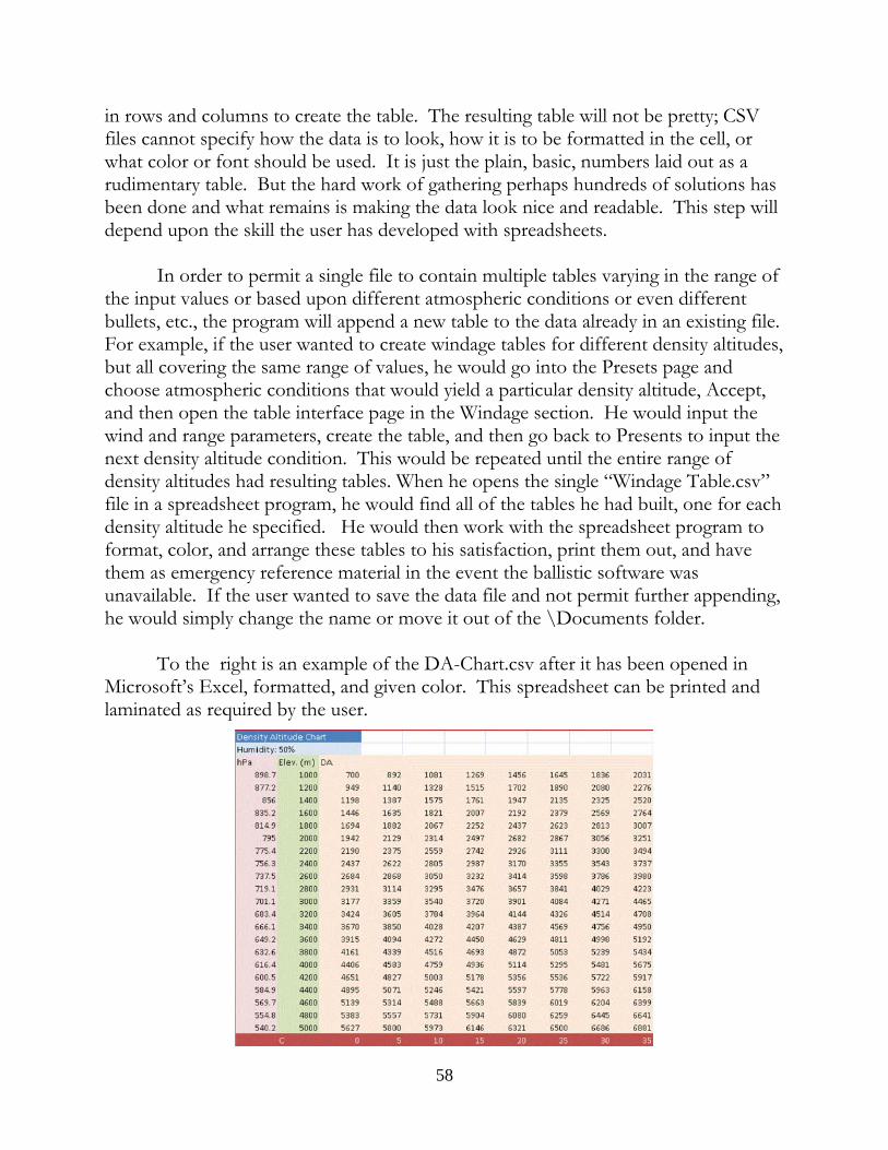
in rows and columns to create the table. The resulting table will not be pretty; CSVfiles cannot specify how the data is to look, how it is to be formatted in the cell, orwhat color or font should be used. It is just the plain, basic, numbers laid out as arudimentary table. But the hard work of gathering perhaps hundreds of solutions hasbeen done and what remains is making the data look nice and readable. This step willdepend upon the skill the user has developed with spreadsheets.
In order to permit a single file to contain multiple tables varying in the range ofthe input values or based upon different atmospheric conditions or even differentbullets, etc., the program will append a new table to the data already in an existing file. For example, if the user wanted to create windage tables for different density altitudes,but all covering the same range of values, he would go into the Presets page andchoose atmospheric conditions that would yield a particular density altitude, Accept,and then open the table interface page in the Windage section. He would input thewind and range parameters, create the table, and then go back to Presents to input thenext density altitude condition. This would be repeated until the entire range ofdensity altitudes had resulting tables. When he opens the single “Windage Table.csv” file in a spreadsheet program, he would find all of the tables he had built, one for eachdensity altitude he specified. He would then work with the spreadsheet program toformat, color, and arrange these tables to his satisfaction, print them out, and havethem as emergency reference material in the event the ballistic software wasunavailable. If the user wanted to save the data file and not permit further appending,he would simply change the name or move it out of the \Documents folder.
To the right is an example of the DA-Chart.csv after it has been opened inMicrosoft’s Excel, formatted, and given color. This spreadsheet can be printed andlaminated as required by the user.
58
Advanced Tools
59
The Target Range Card
Clicking on the “Targeting” button at the top of the main page brings up theTarget Range Card, probably the most powerful and meaningful display of data in theprogram, outside of the main page. This data presentation combines the functionalityof the Target List, Elevation Table, Windage Table, Map, Direct, GPS, and LaserRanging functions, into a single location to rapidly create and catalog multiple targetsfrom a single firing position, presenting the firing solution data in the form ofelevation hold-offs and relative windage values for each target such that the shootercan rapidly acquire any of the listed targets without dialing the firing solution. Second,the created target list can be edited, modified, and saved as individual targets and,more appropriately, a target group all from this work area. In addition, each of theindividual targets created, as well as the related FFP, is also accessible from the TargetList and are editable in the various locations in the program for editing target and FFPprofiles.
Review of Target File TypesThe program allows for the creation of two types of target related files: the
“Direct” ranging file and the “Position” or “Location” file. The direct ranging file is asimple file as it merely comprises a range, bearing and angle. It is not connected toany particular location on Earth and is compatible with any loaded FFP. This type offile is included in the program to enable the creation of target files in circumstanceswhere the current FFP coordinates are not known. In the absence of FFPcoordinates, it is not possible to calculate target coordinates and therefore it is notpossible to create location or position target files. These simple range-only files canbe loaded under any circumstance since doing so only means the loading of a range,bearing and angle to the main page of the software.
The second type of file is the “Position” or “Location” file; it consists of thelatitude, longitude and altitude of a specific location on Earth. In order to use aposition file it is necessary to pair the target position with a shooting position, an FFPfile which contains the latitude, longitude and altitude of a firing position. Once thecoordinates of the FFP and target are known, the range, bearing and angle of the shotcan be calculated. Obviously, position target files have no real meaning in obtaining afiring solution in the absence of an FFP location since it always takes two mappositions to calculate the range, bearing and angle components that form the basis forcomputing a firing solution. Consequently, while it is possible to load an FFP file inthe absence of a target file, the reverse is not true. Loading a Position target file byitself has no meaning to the program since it not possible to do anything with a targetlocation by itself.
60
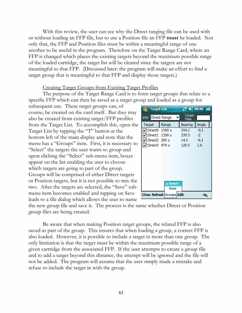
With this review, the user can see why the Direct ranging file can be used withor without loading an FFP file, but to use a Position file an FFP must be loaded. Notonly that, the FFP and Position files must be within a meaningful range of oneanother to be useful in the program. Therefore on the Target Range Card, where anFFP is changed which places the existing targets beyond the maximum possible rangeof the loaded cartridge, the target list will be cleared since the targets are notmeaningful to that FFP. (Discussed later: the program will make an effort to find atarget group that is meaningful to that FFP and display those targets.)
Creating Target Groups from Existing Target ProfilesThe purpose of the Target Range Card is to form target groups that relate to a
specific FFP which can then be saved as a target group and loaded as a group forsubsequent use. These target groups can, ofcourse, be created on the card itself. But they mayalso be created from existing target/FFP profilesfrom the Target List. To accomplish this, open theTarget List by tapping the “T” button at thebottom left of the main display and note that themenu has a “Groups” item. First, it is necessary to“Select” the targets the user wants to group andupon clicking the “Select” sub-menu item, boxesappear on the list enabling the user to choosewhich targets are going to part of the group. Groups will be comprised of either Direct targetsor Position targets, but it is not possible to mix thetwo. After the targets are selected, the “Save” sub-menu item becomes enabled and tapping on Saveleads to a file dialog which allows the user to namethe new group file and save it. The process is the same whether Direct or Positiongroup files are being created.
Be aware that when making Position target groups, the related FFP is alsosaved as part of the group. This insures that when loading a group, a correct FFP isalso loaded. However, it is possible to include a target in more than one group. Theonly limitation is that the target must be within the maximum possible range of agiven cartridge from the associated FFP. If the user attempts to create a group fileand to add a target beyond this distance, the attempt will be ignored and the file willnot be added. The program will assume that the user simply made a mistake andrefuse to include the target in with the group.
61
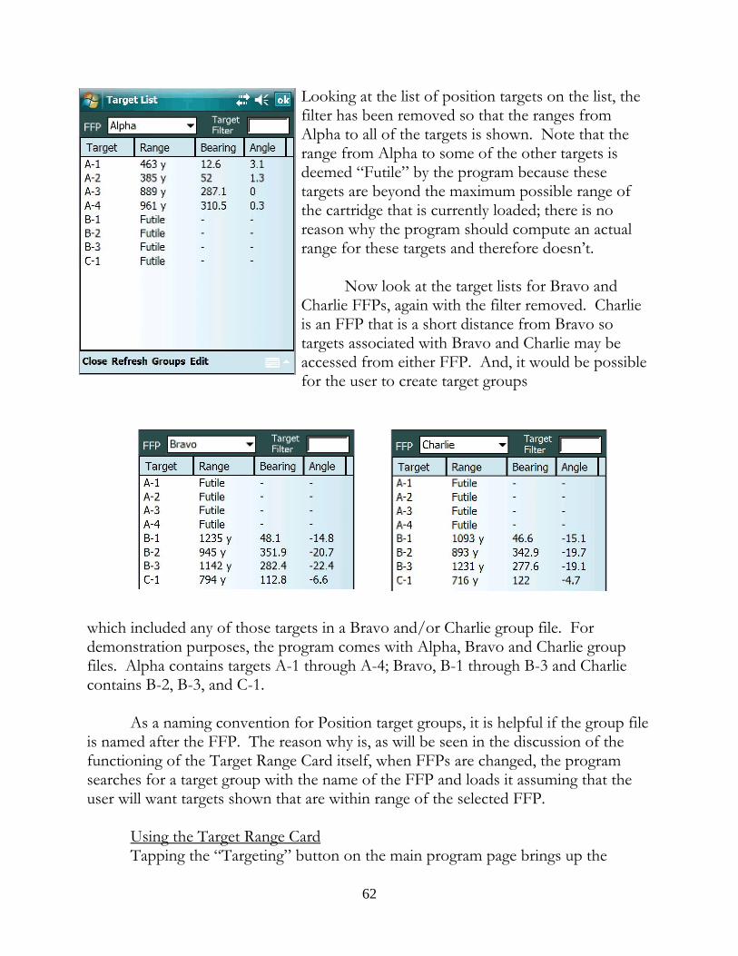
Looking at the list of position targets on the list, thefilter has been removed so that the ranges fromAlpha to all of the targets is shown. Note that therange from Alpha to some of the other targets isdeemed “Futile” by the program because thesetargets are beyond the maximum possible range ofthe cartridge that is currently loaded; there is noreason why the program should compute an actualrange for these targets and therefore doesn’t.
Now look at the target lists for Bravo andCharlie FFPs, again with the filter removed. Charlieis an FFP that is a short distance from Bravo sotargets associated with Bravo and Charlie may beaccessed from either FFP. And, it would be possiblefor the user to create target groups
which included any of those targets in a Bravo and/or Charlie group file. Fordemonstration purposes, the program comes with Alpha, Bravo and Charlie groupfiles. Alpha contains targets A-1 through A-4; Bravo, B-1 through B-3 and Charliecontains B-2, B-3, and C-1.
As a naming convention for Position target groups, it is helpful if the group fileis named after the FFP. The reason why is, as will be seen in the discussion of thefunctioning of the Target Range Card itself, when FFPs are changed, the programsearches for a target group with the name of the FFP and loads it assuming that theuser will want targets shown that are within range of the selected FFP.
Using the Target Range CardTapping the “Targeting” button on the main program page brings up the
62
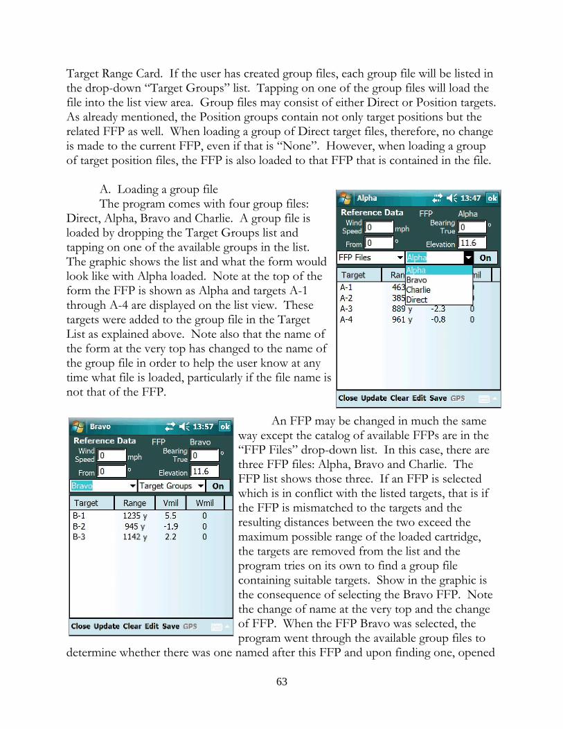
Target Range Card. If the user has created group files, each group file will be listed inthe drop-down “Target Groups” list. Tapping on one of the group files will load thefile into the list view area. Group files may consist of either Direct or Position targets. As already mentioned, the Position groups contain not only target positions but therelated FFP as well. When loading a group of Direct target files, therefore, no changeis made to the current FFP, even if that is “None”. However, when loading a groupof target position files, the FFP is also loaded to that FFP that is contained in the file.
A. Loading a group fileThe program comes with four group files:
Direct, Alpha, Bravo and Charlie. A group file isloaded by dropping the Target Groups list andtapping on one of the available groups in the list. The graphic shows the list and what the form wouldlook like with Alpha loaded. Note at the top of theform the FFP is shown as Alpha and targets A-1through A-4 are displayed on the list view. Thesetargets were added to the group file in the TargetList as explained above. Note also that the name ofthe form at the very top has changed to the name ofthe group file in order to help the user know at anytime what file is loaded, particularly if the file name isnot that of the FFP.
An FFP may be changed in much the sameway except the catalog of available FFPs are in the“FFP Files” drop-down list. In this case, there arethree FFP files: Alpha, Bravo and Charlie. TheFFP list shows those three. If an FFP is selectedwhich is in conflict with the listed targets, that is ifthe FFP is mismatched to the targets and theresulting distances between the two exceed themaximum possible range of the loaded cartridge,the targets are removed from the list and theprogram tries on its own to find a group filecontaining suitable targets. Show in the graphic isthe consequence of selecting the Bravo FFP. Notethe change of name at the very top and the changeof FFP. When the FFP Bravo was selected, theprogram went through the available group files to
determine whether there was one named after this FFP and upon finding one, opened
63
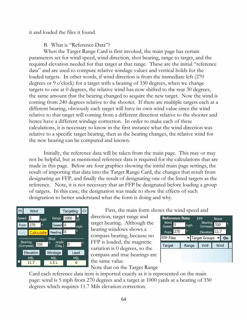
it and loaded the files it found.
B. What is “Reference Data”?When the Target Range Card is first invoked, the main page has certain
parameters set for wind speed, wind direction, shot bearing, range to target, and therequired elevation needed for that target at that range. These are the initial “referencedata” and are used to compute relative windage values and vertical holds for theloaded targets. In other words, if wind direction is from the immediate left (270degrees or 9 o’clock) for a target with a bearing of 330 degrees, when we changetargets to one at 0 degrees, the relative wind has now shifted to the rear 30 degrees,the same amount that the bearing changed to acquire the new target. Now the wind iscoming from 240 degrees relative to the shooter. If there are multiple targets each at adifferent bearing, obviously each target will have its own wind value since the windrelative to that target will coming from a different direction relative to the shooter andhence have a different windage correction. In order to make each of thesecalculations, it is necessary to know in the first instance what the wind direction wasrelative to a specific target bearing, then as the bearing changes, the relative wind forthe new bearing can be computed and known.
Initially, the reference data will be taken from the main page. This may or maynot be helpful, but as mentioned reference data is required for the calculations that aremade in this page. Below are four graphics showing the initial main page settings, theresult of importing that data into the Target Range Card, the changes that result fromdesignating an FFP, and finally the result of designating one of the listed targets as thereference. Note, it is not necessary that an FFP be designated before loading a groupof targets. In this case, the designation was made to show the effects of suchdesignation to better understand what the form is doing and why.
First, the main form shows the wind speed anddirection, target range andtarget bearing. Although thebearing windows shows acompass bearing, because noFFP is loaded, the magneticvariation is 0 degrees, so thecompass and true bearings arethe same value. Note that on the Target Range
Card each reference data item is imported exactly as it is represented on the mainpage: wind is 5 mph from 270 degrees and a target at 1000 yards at a bearing of 330degrees which requires 11.7 Mils elevation correction.
64
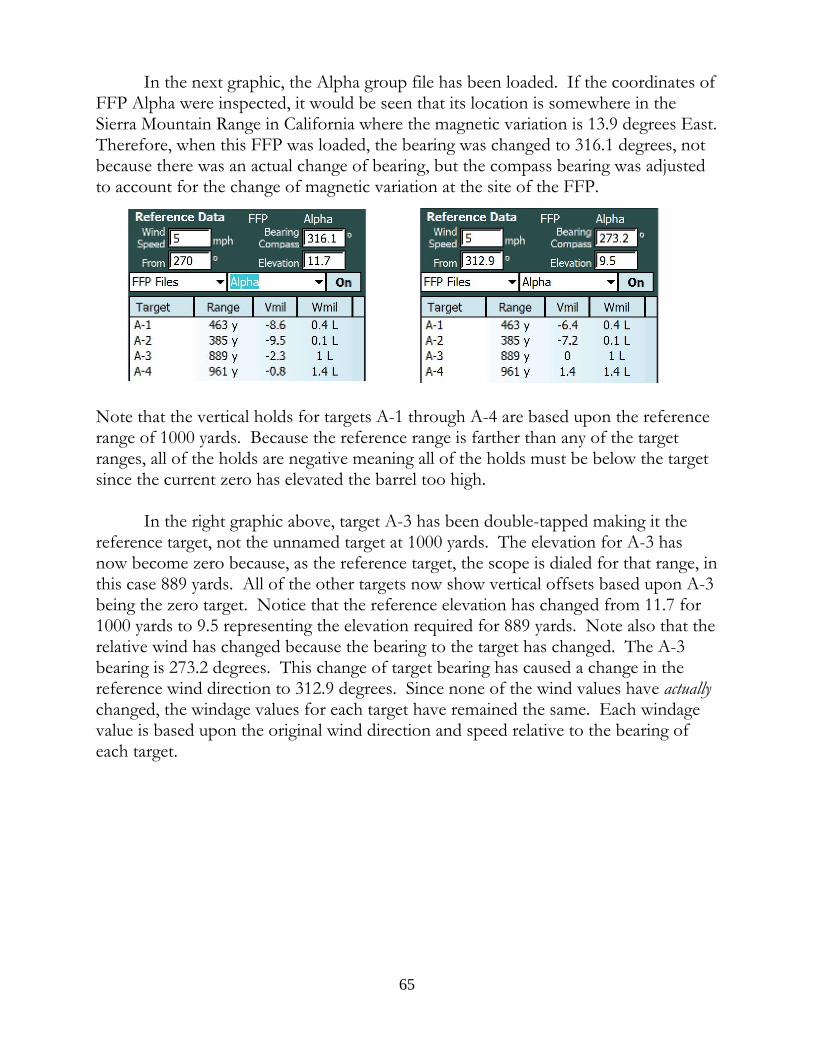
In the next graphic, the Alpha group file has been loaded. If the coordinates ofFFP Alpha were inspected, it would be seen that its location is somewhere in theSierra Mountain Range in California where the magnetic variation is 13.9 degrees East. Therefore, when this FFP was loaded, the bearing was changed to 316.1 degrees, notbecause there was an actual change of bearing, but the compass bearing was adjustedto account for the change of magnetic variation at the site of the FFP.
Note that the vertical holds for targets A-1 through A-4 are based upon the referencerange of 1000 yards. Because the reference range is farther than any of the targetranges, all of the holds are negative meaning all of the holds must be below the targetsince the current zero has elevated the barrel too high.
In the right graphic above, target A-3 has been double-tapped making it thereference target, not the unnamed target at 1000 yards. The elevation for A-3 hasnow become zero because, as the reference target, the scope is dialed for that range, inthis case 889 yards. All of the other targets now show vertical offsets based upon A-3being the zero target. Notice that the reference elevation has changed from 11.7 for1000 yards to 9.5 representing the elevation required for 889 yards. Note also that therelative wind has changed because the bearing to the target has changed. The A-3bearing is 273.2 degrees. This change of target bearing has caused a change in thereference wind direction to 312.9 degrees. Since none of the wind values have actuallychanged, the windage values for each target have remained the same. Each windagevalue is based upon the original wind direction and speed relative to the bearing ofeach target.
65
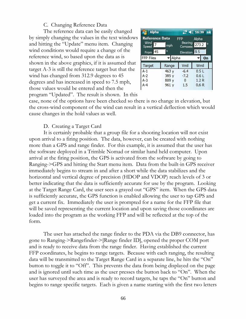
C. Changing Reference DataThe reference data can be easily changed
by simply changing the values in the text windowsand hitting the “Update” menu item. Changingwind conditions would require a change of thereference wind, so based upon the data as isshown in the above graphics, if it is assumed thattarget A-3 is still the reference target but that thewind has changed from 312.9 degrees to 45degrees and has increased in speed to 7.5 mph,those values would be entered and then theprogram “Updated”. The result is shown. In thiscase, none of the options have been checked so there is no change in elevation, butthe cross-wind component of the wind can result in a vertical deflection which wouldcause changes in the hold values as well.
D. Creating a Target CardIt is certainly probable that a group file for a shooting location will not exist
upon arrival to a firing position. The data, however, can be created with nothingmore than a GPS and range finder. For this example, it is assumed that the user hasthe software deployed in a Trimble Nomad or similar hand held computer. Uponarrival at the firing position, the GPS is activated from the software by going toRanging->GPS and hitting the Start menu item. Data from the built-in GPS receiverimmediately begins to stream in and after a short while the data stabilizes and thehorizontal and vertical degree of precision (HDOP and VDOP) reach levels of 3 orbetter indicating that the data is sufficiently accurate for use by the program. Lookingat the Target Range Card, the user sees a grayed out “GPS” item. When the GPS datais sufficiently accurate, the GPS function is enabled allowing the user to tap GPS andget a current fix. Immediately the user is prompted for a name for the FFP file thatwill be saved representing the current location and upon saving those coordinates areloaded into the program as the working FFP and will be reflected at the top of theform.
The user has attached the range finder to the PDA via the DB9 connector, hasgone to Ranging->Rangefinder->[Range finder ID], opened the proper COM portand is ready to receive data from the range finder. Having established the currentFFP coordinates, he begins to range targets. Because with each ranging, the resultingdata will be transmitted to the Target Range Card in a separate line, he hits the “On”button to toggle it to “Off”. This prevents the data from being displayed on the pageand is ignored until such time as the user presses the button back to “On”. When theuser has surveyed the area and is ready to record targets, he taps the “On” button andbegins to range specific targets. Each is given a name starting with the first two letters
66
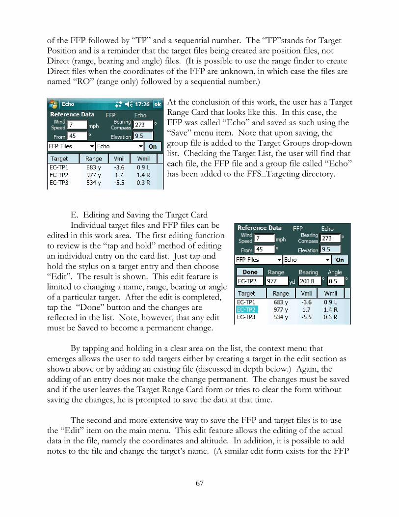
of the FFP followed by “TP” and a sequential number. The “TP”stands for TargetPosition and is a reminder that the target files being created are position files, notDirect (range, bearing and angle) files. (It is possible to use the range finder to createDirect files when the coordinates of the FFP are unknown, in which case the files arenamed “RO” (range only) followed by a sequential number.)
At the conclusion of this work, the user has a TargetRange Card that looks like this. In this case, theFFP was called “Echo” and saved as such using the“Save” menu item. Note that upon saving, thegroup file is added to the Target Groups drop-downlist. Checking the Target List, the user will find thateach file, the FFP file and a group file called “Echo”has been added to the FFS_Targeting directory.
E. Editing and Saving the Target CardIndividual target files and FFP files can be
edited in this work area. The first editing functionto review is the “tap and hold” method of editingan individual entry on the card list. Just tap andhold the stylus on a target entry and then choose“Edit”. The result is shown. This edit feature islimited to changing a name, range, bearing or angleof a particular target. After the edit is completed,tap the “Done” button and the changes arereflected in the list. Note, however, that any editmust be Saved to become a permanent change.
By tapping and holding in a clear area on the list, the context menu thatemerges allows the user to add targets either by creating a target in the edit section asshown above or by adding an existing file (discussed in depth below.) Again, theadding of an entry does not make the change permanent. The changes must be savedand if the user leaves the Target Range Card form or tries to clear the form withoutsaving the changes, he is prompted to save the data at that time.
The second and more extensive way to save the FFP and target files is to usethe “Edit” item on the main menu. This edit feature allows the editing of the actualdata in the file, namely the coordinates and altitude. In addition, it is possible to addnotes to the file and change the target’s name. (A similar edit form exists for the FFP
67
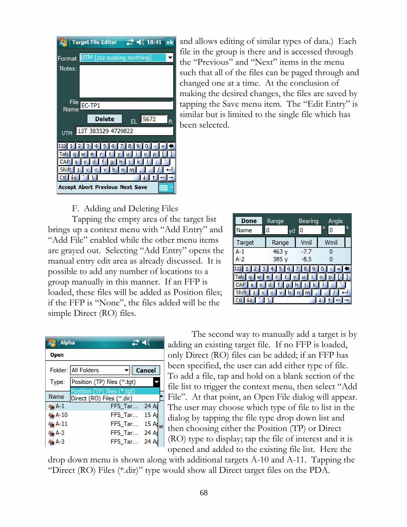
and allows editing of similar types of data.) Eachfile in the group is there and is accessed throughthe “Previous” and “Next” items in the menusuch that all of the files can be paged through andchanged one at a time. At the conclusion ofmaking the desired changes, the files are saved bytapping the Save menu item. The “Edit Entry” issimilar but is limited to the single file which hasbeen selected.
F. Adding and Deleting FilesTapping the empty area of the target list
brings up a context menu with “Add Entry” and“Add File” enabled while the other menu itemsare grayed out. Selecting “Add Entry” opens themanual entry edit area as already discussed. It ispossible to add any number of locations to agroup manually in this manner. If an FFP isloaded, these files will be added as Position files;if the FFP is “None”, the files added will be thesimple Direct (RO) files.
The second way to manually add a target is byadding an existing target file. If no FFP is loaded,only Direct (RO) files can be added; if an FFP hasbeen specified, the user can add either type of file. To add a file, tap and hold on a blank section of thefile list to trigger the context menu, then select “AddFile”. At that point, an Open File dialog will appear. The user may choose which type of file to list in thedialog by tapping the file type drop down list andthen choosing either the Position (TP) or Direct(RO) type to display; tap the file of interest and it isopened and added to the existing file list. Here the
drop down menu is shown along with additional targets A-10 and A-11. Tapping the“Direct (RO) Files (*.dir)” type would show all Direct target files on the PDA.
68
It is important to note that if a Direct (RO) file is selected for addition to a listof Position files, the range only file data will be converted into Position data; in otherwords, upon adding the file, its range, bearing and angle data will be extracted and thecoordinates for a target at that location from the current FFP will be computed andheld in a data structure that will be saved should the user desire to do so. At thatpoint, a new Position file will be created on Save which may have the same name asthe Direct (RO) file, but will have the “.tgt” extension and will be a Position (TP) typeof file.
The main menu also has “Delete” functions as a sub-item in the “Edit” menu. “Delete” means to permanently destroy a file which is to be contrasted with the“Remove” function in the context menu. “Remove” means to take the selected fileout of the current list of targets but the file itself, assuming such a file existed in thefirst place, is left alone. “Delete”, however, means to destroy the file itselfpermanently.
The program allows the user to “Delete” FFP files, Group files and Targetfiles. The delete target files function exposes both the Direct (RO) and Position (TP)files to the user for selection and does so in a manner similar to the Add File process. The Delete File dialog has a drop down list so the user can choose to view Direct orPosition files for deletion candidates.
G. Clearing the Target Range CardThe Clearing function is separated into clearing the FFP, clearing the targets,
and clearing both. When the FFP is cleared, the program is put into a state where it isnot tied to any location on Earth. In that condition, when attaching a range finderand obtaining ranging data through the serial port, the target entries will be named“RO” plus a consecutive number. These will be saved as simple Direct files holding arange, bearing and angle only.
When an FFP is loaded and when a target is double tapped to become thereference target, the target and FFP names are transmitted to the program in general. Upon closing the Target Range Card, the user will see the target and FFP name nextto the Target List button. In addition, the target and FFP names will appear in theMap Ranging form, the Target and FFP editing forms, and the Presets form. Uponclearing one or both, the program signifies the absence of a named entity with“None” in the place formerly occupied by a file name.
H. Matching Elevation and Windage Units to the ReticleIf a coordinated scope is being used, i.e. a scope that has Mil reticle and Mil
turrets or an MOA reticle and MOA turrets, the units shown on the V and Wcolumns will reflect the proper units. However, where an uncoordinated scope is
69
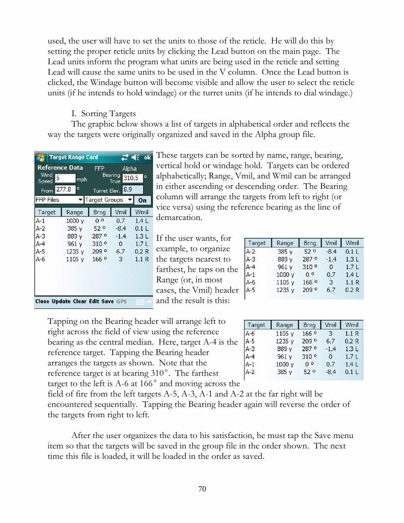
used, the user will have to set the units to those of the reticle. He will do this bysetting the proper reticle units by clicking the Lead button on the main page. TheLead units inform the program what units are being used in the reticle and settingLead will cause the same units to be used in the V column. Once the Lead button isclicked, the Windage button will become visible and allow the user to select the reticleunits (if he intends to hold windage) or the turret units (if he intends to dial windage.)
I. Sorting TargetsThe graphic below shows a list of targets in alphabetical order and reflects the
way the targets were originally organized and saved in the Alpha group file.
These targets can be sorted by name, range, bearing,vertical hold or windage hold. Targets can be orderedalphabetically; Range, Vmil, and Wmil can be arrangedin either ascending or descending order. The Bearingcolumn will arrange the targets from left to right (orvice versa) using the reference bearing as the line ofdemarcation.
If the user wants, forexample, to organizethe targets nearest tofarthest, he taps on theRange (or, in mostcases, the Vmil) headerand the result is this:
Tapping on the Bearing header will arrange left toright across the field of view using the referencebearing as the central median. Here, target A-4 is thereference target. Tapping the Bearing headerarranges the targets as shown. Note that thereference target is at bearing 310E. The farthesttarget to the left is A-6 at 166E and moving across thefield of fire from the left targets A-5, A-3, A-1 and A-2 at the far right will beencountered sequentially. Tapping the Bearing header again will reverse the order ofthe targets from right to left.
After the user organizes the data to his satisfaction, he must tap the Save menuitem so that the targets will be saved in the group file in the order shown. The nexttime this file is loaded, it will be loaded in the order as saved.
70
J. Using the Capture FunctionThe content of the Target Range Card can be exported in the form of a CSV
(comma separated values) text file which can be opened in Excel® or similarspreadsheet for the purpose of creating a hard copy of the range card. The user is freeto modify the data presented, organizing it in ways that best fit his preferences. Toobtain the data contained in the range card, select Edit->Capture. All data on thecard will be written to a CSV file which the user can find in the \Documents directoryon the SD card. Copy this file to a desktop computer for opening in a spreadsheetand thereafter editing the columns, presentation, format and the rest.
If the user wants to make several range cards for the same bullet profile butwith changing atmospheric values, simply create the file as instructed above but leavethe data file in \Documents, exit to the Presets, make changes to the atmosphericvariables, Accept the changes, and Capture the data again. The new card data will beappended to the original file. The user may repeat this sequence until all of thevarious conditions for that cartridge have been exhausted. At that point, move the fileto the desktop computer, open it in a spreadsheet program and the user will seeindividual blocks for each condition saved.
LOS Metrics
The purpose of this work area is to enable a user to know where the bullet iswith respect the his line of sight (LOS) to the target all the way from muzzle to target. As the bullet leaves the muzzle it is well below the LOS of the shooter who is lookingthrough the scope. From that point the bullet has a path that moves upward and atsome location down range will cross the LOS and continue in its arc to the target. Fardown range, the bullet will again cross the LOS. A well placed shot means that thissecond intersection of the LOS is precisely at the vertical plane of the target. In thatevent, the bullet will strike the target exactly at the point of aim.
Knowing the location of the bullet with respect to the LOS can solve a host ofproblems. One example relates to shooting through an opening to get to a targetbeyond. In order to shoot through an opening, the problem to be solved is to locatethe path of the bullet with respect to the LOS in order to determine whether thebullet has room to pass through the opening at the vertical plane where the opening issituated. This will, of course, depend directly upon the distance between the muzzleof the rifle, the down range location of the opening, its size, and the bullet’s trajectorywith respect to the LOS of the shooter looking through the opening at the target. This is a generalized problem. The “opening” can be the space under a bridge, aclearing in the trees, or a hole in the wall. Whenever a shooter needs to ascertain thelocation of the bullet at some point along the LOS for any reason, this is theworkspace to use.
71
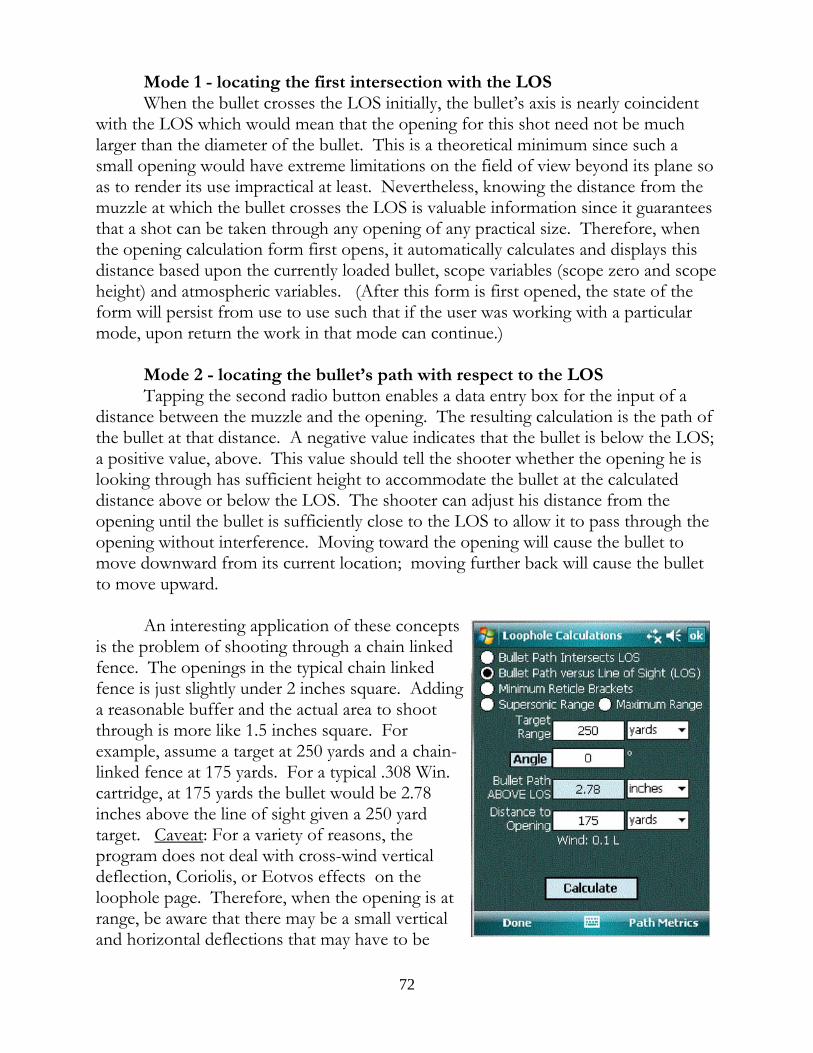
Mode 1 - locating the first intersection with the LOSWhen the bullet crosses the LOS initially, the bullet’s axis is nearly coincident
with the LOS which would mean that the opening for this shot need not be muchlarger than the diameter of the bullet. This is a theoretical minimum since such asmall opening would have extreme limitations on the field of view beyond its plane soas to render its use impractical at least. Nevertheless, knowing the distance from themuzzle at which the bullet crosses the LOS is valuable information since it guaranteesthat a shot can be taken through any opening of any practical size. Therefore, whenthe opening calculation form first opens, it automatically calculates and displays thisdistance based upon the currently loaded bullet, scope variables (scope zero and scopeheight) and atmospheric variables. (After this form is first opened, the state of theform will persist from use to use such that if the user was working with a particularmode, upon return the work in that mode can continue.)
Mode 2 - locating the bullet’s path with respect to the LOSTapping the second radio button enables a data entry box for the input of a
distance between the muzzle and the opening. The resulting calculation is the path ofthe bullet at that distance. A negative value indicates that the bullet is below the LOS;a positive value, above. This value should tell the shooter whether the opening he islooking through has sufficient height to accommodate the bullet at the calculateddistance above or below the LOS. The shooter can adjust his distance from theopening until the bullet is sufficiently close to the LOS to allow it to pass through theopening without interference. Moving toward the opening will cause the bullet tomove downward from its current location; moving further back will cause the bulletto move upward.
An interesting application of these conceptsis the problem of shooting through a chain linkedfence. The openings in the typical chain linkedfence is just slightly under 2 inches square. Addinga reasonable buffer and the actual area to shootthrough is more like 1.5 inches square. Forexample, assume a target at 250 yards and a chain-linked fence at 175 yards. For a typical .308 Win.cartridge, at 175 yards the bullet would be 2.78inches above the line of sight given a 250 yardtarget. Caveat: For a variety of reasons, theprogram does not deal with cross-wind verticaldeflection, Coriolis, or Eotvos effects on theloophole page. Therefore, when the opening is atrange, be aware that there may be a small verticaland horizontal deflections that may have to be
72
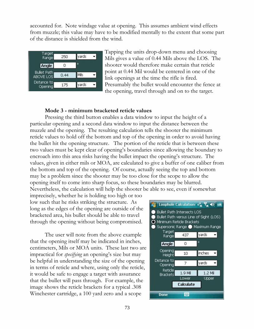
accounted for. Note windage value at opening. This assumes ambient wind effectsfrom muzzle; this value may have to be modified mentally to the extent that some partof the distance is shielded from the wind.
Tapping the units drop-down menu and choosingMils gives a value of 0.44 Mils above the LOS. Theshooter would therefore make certain that reticlepoint at 0.44 Mil would be centered in one of thelink openings at the time the rifle is fired. Presumably the bullet would encounter the fence atthe opening, travel through and on to the target.
Mode 3 - minimum bracketed reticle valuesPressing the third button enables a data window to input the height of a
particular opening and a second data window to input the distance between themuzzle and the opening. The resulting calculation tells the shooter the minimumreticle values to hold off the bottom and top of the opening in order to avoid havingthe bullet hit the opening structure. The portion of the reticle that is between thesetwo values must be kept clear of opening’s boundaries since allowing the boundary toencroach into this area risks having the bullet impact the opening’s structure. Thevalues, given in either mils or MOA, are calculated to give a buffer of one caliber fromthe bottom and top of the opening. Of course, actually seeing the top and bottommay be a problem since the shooter may be too close for the scope to allow theopening itself to come into sharp focus, so these boundaries may be blurred. Nevertheless, the calculation will help the shooter be able to see, even if somewhatimprecisely, whether he is holding too high or toolow such that he risks striking the structure. Aslong as the edges of the opening are outside of thebracketed area, his bullet should be able to travelthrough the opening without being compromised.
The user will note from the above examplethat the opening itself may be indicated in inches,centimeters, Mils or MOA units. These last two areimpractical for specifying an opening’s size but maybe helpful in understanding the size of the openingin terms of reticle and where, using only the reticle,it would be safe to engage a target with assurancethat the bullet will pass through. For example, theimage shows the reticle brackets for a typical .308Winchester cartridge, a 100 yard zero and a scope
73
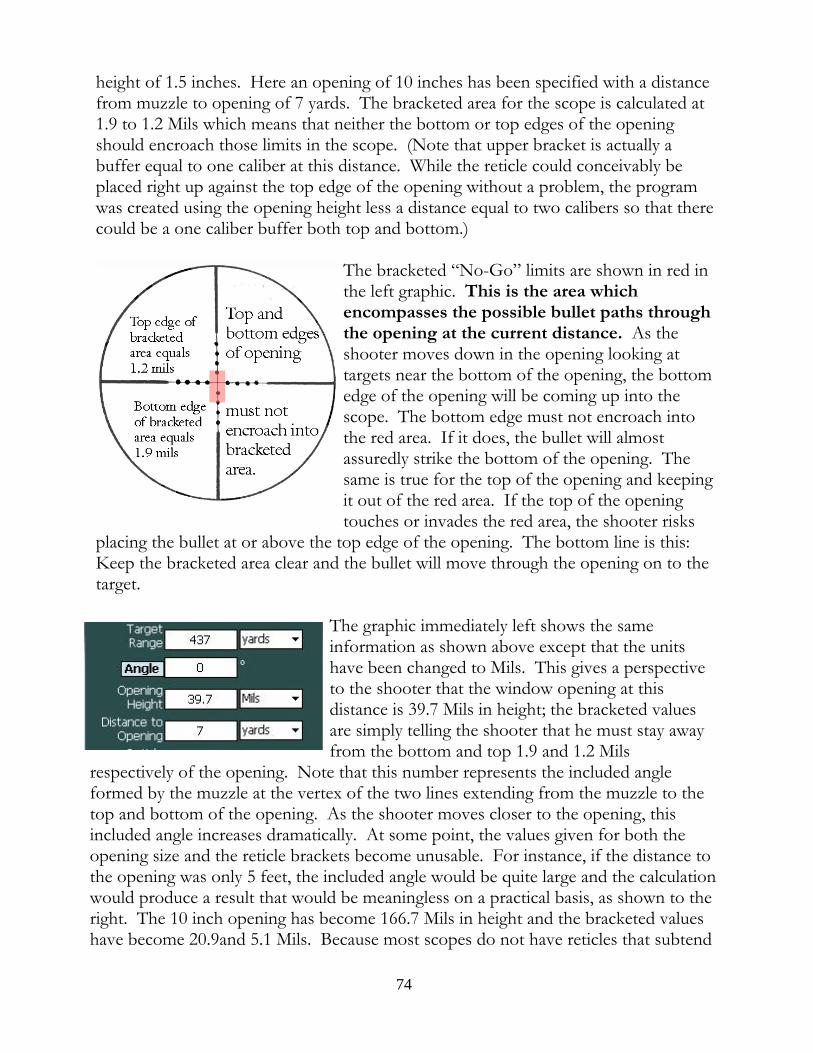
height of 1.5 inches. Here an opening of 10 inches has been specified with a distancefrom muzzle to opening of 7 yards. The bracketed area for the scope is calculated at1.9 to 1.2 Mils which means that neither the bottom or top edges of the openingshould encroach those limits in the scope. (Note that upper bracket is actually abuffer equal to one caliber at this distance. While the reticle could conceivably beplaced right up against the top edge of the opening without a problem, the programwas created using the opening height less a distance equal to two calibers so that therecould be a one caliber buffer both top and bottom.)
The bracketed “No-Go” limits are shown in red inthe left graphic. This is the area whichencompasses the possible bullet paths throughthe opening at the current distance. As theshooter moves down in the opening looking attargets near the bottom of the opening, the bottomedge of the opening will be coming up into thescope. The bottom edge must not encroach intothe red area. If it does, the bullet will almostassuredly strike the bottom of the opening. Thesame is true for the top of the opening and keepingit out of the red area. If the top of the openingtouches or invades the red area, the shooter risks
placing the bullet at or above the top edge of the opening. The bottom line is this:Keep the bracketed area clear and the bullet will move through the opening on to thetarget.
The graphic immediately left shows the sameinformation as shown above except that the unitshave been changed to Mils. This gives a perspectiveto the shooter that the window opening at thisdistance is 39.7 Mils in height; the bracketed valuesare simply telling the shooter that he must stay awayfrom the bottom and top 1.9 and 1.2 Mils
respectively of the opening. Note that this number represents the included angleformed by the muzzle at the vertex of the two lines extending from the muzzle to thetop and bottom of the opening. As the shooter moves closer to the opening, thisincluded angle increases dramatically. At some point, the values given for both theopening size and the reticle brackets become unusable. For instance, if the distance tothe opening was only 5 feet, the included angle would be quite large and the calculationwould produce a result that would be meaningless on a practical basis, as shown to theright. The 10 inch opening has become 166.7 Mils in height and the bracketed valueshave become 20.9and 5.1 Mils. Because most scopes do not have reticles that subtend
74
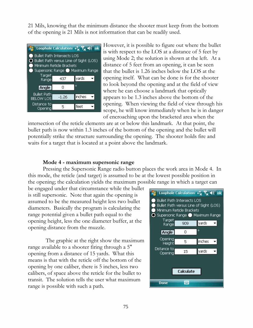
21 Mils, knowing that the minimum distance the shooter must keep from the bottomof the opening is 21 Mils is not information that can be readily used.
However, it is possible to figure out where the bulletis with respect to the LOS at a distance of 5 feet byusing Mode 2; the solution is shown at the left. At adistance of 5 feet from an opening, it can be seenthat the bullet is 1.26 inches below the LOS at theopening itself. What can be done is for the shooterto look beyond the opening and at the field of viewwhere he can choose a landmark that opticallyappears to be 1.3 inches above the bottom of theopening. When viewing the field of view through hisscope, he will know immediately when he is in dangerof encroaching upon the bracketed area when the
intersection of the reticle elements are at or below this landmark. At that point, thebullet path is now within 1.3 inches of the bottom of the opening and the bullet willpotentially strike the structure surrounding the opening. The shooter holds fire andwaits for a target that is located at a point above the landmark.
Mode 4 - maximum supersonic rangePressing the Supersonic Range radio button places the work area in Mode 4. In
this mode, the reticle (and target) is assumed to be at the lowest possible position inthe opening; the calculation yields the maximum possible range in which a target canbe engaged under that circumstance while the bulletis still supersonic. Note that again the opening isassumed to be the measured height less two bulletdiameters. Basically the program is calculating therange potential given a bullet path equal to theopening height, less the one diameter buffer, at theopening distance from the muzzle.
The graphic at the right show the maximumrange available to a shooter firing through a 5"opening from a distance of 15 yards. What thismeans is that with the reticle off the bottom of theopening by one caliber, there is 5 inches, less twocalibers, of space above the reticle for the bullet totransit. The solution tells the user what maximumrange is possible with such a path.
75
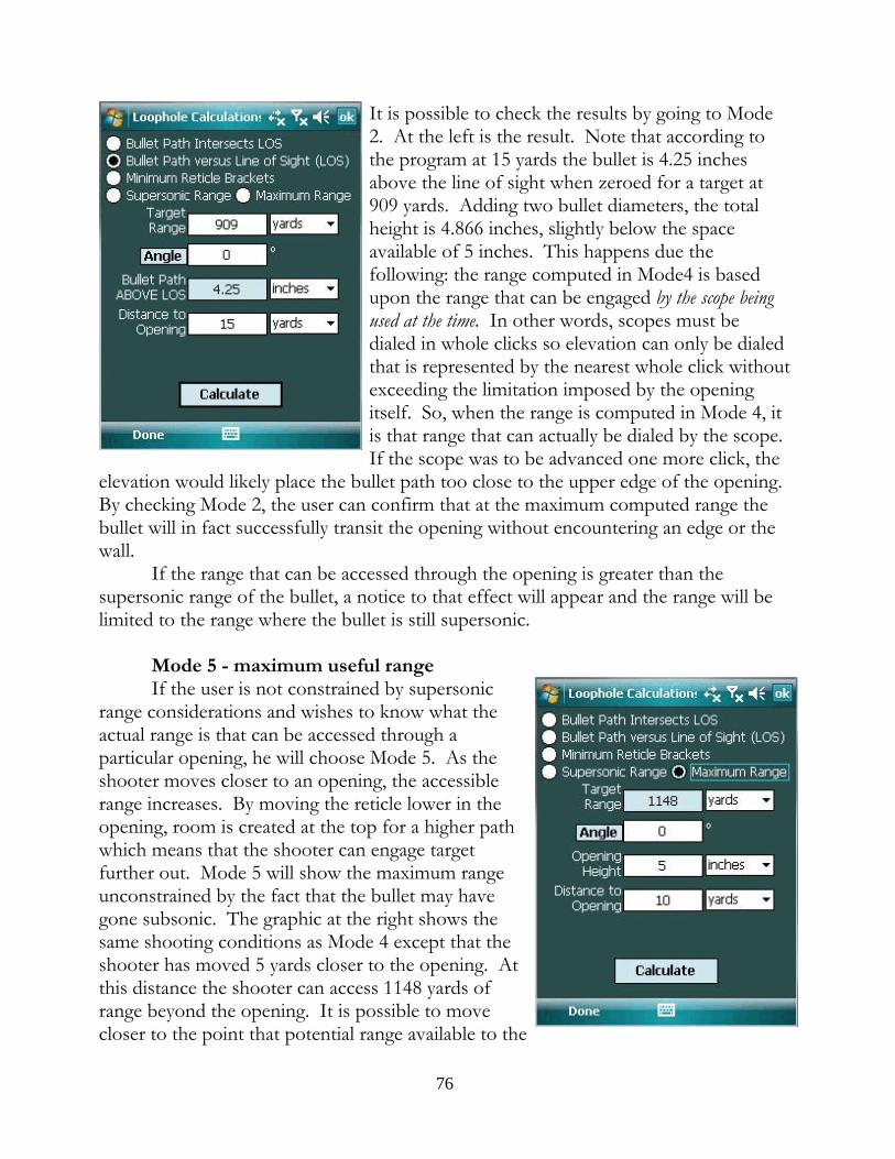
It is possible to check the results by going to Mode2. At the left is the result. Note that according tothe program at 15 yards the bullet is 4.25 inchesabove the line of sight when zeroed for a target at909 yards. Adding two bullet diameters, the totalheight is 4.866 inches, slightly below the spaceavailable of 5 inches. This happens due thefollowing: the range computed in Mode4 is basedupon the range that can be engaged by the scope beingused at the time. In other words, scopes must bedialed in whole clicks so elevation can only be dialedthat is represented by the nearest whole click withoutexceeding the limitation imposed by the openingitself. So, when the range is computed in Mode 4, itis that range that can actually be dialed by the scope. If the scope was to be advanced one more click, the
elevation would likely place the bullet path too close to the upper edge of the opening. By checking Mode 2, the user can confirm that at the maximum computed range thebullet will in fact successfully transit the opening without encountering an edge or thewall.
If the range that can be accessed through the opening is greater than thesupersonic range of the bullet, a notice to that effect will appear and the range will belimited to the range where the bullet is still supersonic.
Mode 5 - maximum useful rangeIf the user is not constrained by supersonic
range considerations and wishes to know what theactual range is that can be accessed through aparticular opening, he will choose Mode 5. As theshooter moves closer to an opening, the accessiblerange increases. By moving the reticle lower in theopening, room is created at the top for a higher pathwhich means that the shooter can engage targetfurther out. Mode 5 will show the maximum rangeunconstrained by the fact that the bullet may havegone subsonic. The graphic at the right shows thesame shooting conditions as Mode 4 except that theshooter has moved 5 yards closer to the opening. Atthis distance the shooter can access 1148 yards ofrange beyond the opening. It is possible to movecloser to the point that potential range available to the
76
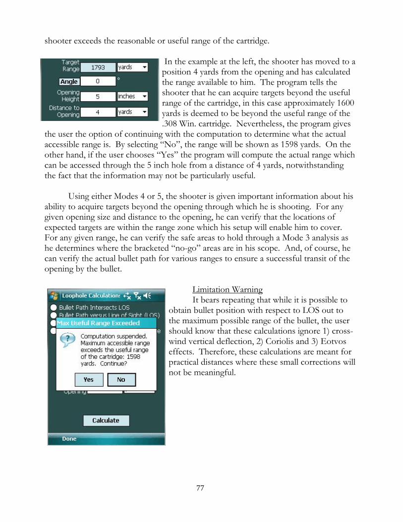
shooter exceeds the reasonable or useful range of the cartridge.
In the example at the left, the shooter has moved to aposition 4 yards from the opening and has calculatedthe range available to him. The program tells theshooter that he can acquire targets beyond the usefulrange of the cartridge, in this case approximately 1600yards is deemed to be beyond the useful range of the.308 Win. cartridge. Nevertheless, the program gives
the user the option of continuing with the computation to determine what the actualaccessible range is. By selecting “No”, the range will be shown as 1598 yards. On theother hand, if the user chooses “Yes” the program will compute the actual range whichcan be accessed through the 5 inch hole from a distance of 4 yards, notwithstandingthe fact that the information may not be particularly useful.
Using either Modes 4 or 5, the shooter is given important information about hisability to acquire targets beyond the opening through which he is shooting. For anygiven opening size and distance to the opening, he can verify that the locations ofexpected targets are within the range zone which his setup will enable him to cover. For any given range, he can verify the safe areas to hold through a Mode 3 analysis ashe determines where the bracketed “no-go” areas are in his scope. And, of course, hecan verify the actual bullet path for various ranges to ensure a successful transit of theopening by the bullet.
Limitation WarningIt bears repeating that while it is possible to
obtain bullet position with respect to LOS out tothe maximum possible range of the bullet, the usershould know that these calculations ignore 1) cross-wind vertical deflection, 2) Coriolis and 3) Eotvoseffects. Therefore, these calculations are meant forpractical distances where these small corrections willnot be meaningful.
77
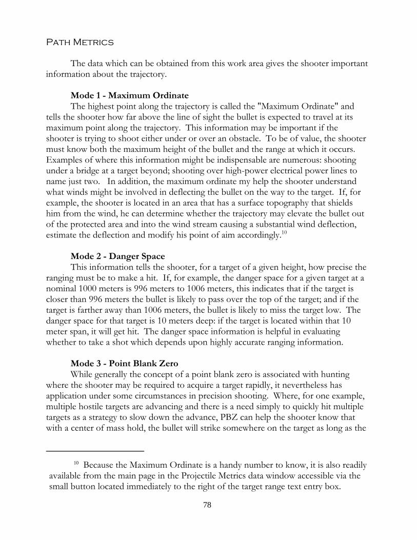
Path Metrics
The data which can be obtained from this work area gives the shooter importantinformation about the trajectory.
Mode 1 - Maximum OrdinateThe highest point along the trajectory is called the "Maximum Ordinate" and
tells the shooter how far above the line of sight the bullet is expected to travel at itsmaximum point along the trajectory. This information may be important if theshooter is trying to shoot either under or over an obstacle. To be of value, the shootermust know both the maximum height of the bullet and the range at which it occurs. Examples of where this information might be indispensable are numerous: shootingunder a bridge at a target beyond; shooting over high-power electrical power lines toname just two. In addition, the maximum ordinate my help the shooter understandwhat winds might be involved in deflecting the bullet on the way to the target. If, forexample, the shooter is located in an area that has a surface topography that shieldshim from the wind, he can determine whether the trajectory may elevate the bullet outof the protected area and into the wind stream causing a substantial wind deflection,estimate the deflection and modify his point of aim accordingly.10
Mode 2 - Danger SpaceThis information tells the shooter, for a target of a given height, how precise the
ranging must be to make a hit. If, for example, the danger space for a given target at anominal 1000 meters is 996 meters to 1006 meters, this indicates that if the target iscloser than 996 meters the bullet is likely to pass over the top of the target; and if thetarget is farther away than 1006 meters, the bullet is likely to miss the target low. Thedanger space for that target is 10 meters deep: if the target is located within that 10meter span, it will get hit. The danger space information is helpful in evaluatingwhether to take a shot which depends upon highly accurate ranging information.
Mode 3 - Point Blank ZeroWhile generally the concept of a point blank zero is associated with hunting
where the shooter may be required to acquire a target rapidly, it nevertheless hasapplication under some circumstances in precision shooting. Where, for one example,multiple hostile targets are advancing and there is a need simply to quickly hit multipletargets as a strategy to slow down the advance, PBZ can help the shooter know thatwith a center of mass hold, the bullet will strike somewhere on the target as long as the
10 Because the Maximum Ordinate is a handy number to know, it is also readilyavailable from the main page in the Projectile Metrics data window accessible via thesmall button located immediately to the right of the target range text entry box.
78
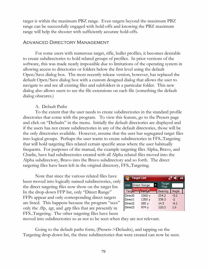
target is within the maximum PBZ range. Even targets beyond the maximum PBZrange can be successfully engaged with hold-offs and knowing the PBZ maximumrange will help the shooter with sufficiently accurate hold-offs.
Advanced Directory Management
For some users with numerous target, rifle, bullet profiles, it becomes desirableto create subdirectories to hold related groups of profiles. In prior versions of thesoftware, this was made nearly impossible due to limitations of the operating system inallowing access to directories or folders below the first level using the defaultOpen/Save dialog box. The most recently release version, however, has replaced thedefault Open/Save dialog box with a custom designed dialog that allows the user tonavigate to and see all existing files and subfolders in a particular folder. This newdialog also allows users to see the file extensions on each file (something the defaultdialog obscures.)
A. Default PathsTo the extent that the user needs to create subdirectories in the standard profile
directories that come with the program. To view this feature, go to the Presets pageand click on “Defaults” in the menu. Initially the default directories are displayed andif the users has not create subdirectories in any of the default directories, those will bethe only directories available. However, assume that the user has segregated target filesinto logical groups. Perhaps the user wants to create subdirectories in FFS_Targetingthat will hold targeting files related certain specific areas where the user habituallyfrequents. For purposes of the manual, the example targeting files Alpha, Bravo, andCharlie, have had subdirectories created with all Alpha related files moved into theAlpha subdirectory, Bravo into the Bravo subdirectory and so forth. The directtargeting files have been left in the original directory, FFS_Targeting.
Note that since the various related files havebeen moved into logically named subdirectories, onlythe direct targeting files now show on the target list. In the drop-down FFP list, only “Direct Range”FFPs appear and only corresponding direct targetsare listed. This happens because the program “sees”only the .ffp, .tgt, and .grp files that are presently inFFS_Targeting. The other targeting files have beenmoved into subdirectories so as not to be seen when they are not relevant.
Going to the default paths form, (Presets->Defaults), and tapping on theTargeting drop-down list, the three subdirectories that were created can now be seen.
79
If subdirectory“Alpha” is chosen,the target list nowshows only AlphaFFPs, targets, and, inthe Target RangeCard, groups.
The reasonwhy this is the case is that as far as the program isconcerned, the new default path to all targeting filesis FFS_Targeting\Alpha and the program will lookonly there for targeting files. If Alpha happens to bethe location where the shooter is going be accessingtargets, this is very convenient since he will not bepresented with non-relevant targets.
The user can, of course, update the targets in the Alpha area by saving additionalAlpha related target in the Alpha subdirectory and those new targets will come to belisted in the Target List.
While the user can change the default path to other profiles, not all changesmake sense. Unless there is a compelling reason to segregate atmosphere profiles, forexample, there isn’t much reason to add subdirectories. Nevertheless, if the needarises, the software can accommodate the need.
B. How to Create New SubfoldersNew folders in profile directories can be created in two ways. The first is to
create the folder while the card is in the PDA. To do that, tap the Start icon (upperleft hand corner of the PDA screen, choose Programs and then tap on the FileExplorer program. This program gives the user access to the file system of the PDA. By navigating Up the file hierarchy, the user will come to the root directory which willlist various directories including the Storage Card or SD Card directory. Tap on thedirectory opens the file system of the software’s SD card. If the user wanted to createa subdirectory in FFS_Targeting, the user would tap the that folder and then tap andhold on an empty space. A context menu would appear which the menu item “NewFolder”. Tapping that will create a new subfolder which the user will then name.
The second way is to remove the SD card and insert it into a desktop or laptopcomputer that has an SD drive. Using Windows Explorer, the sequence is the same. Find the SD drive, click on it to view the various directories on the card. Find the
80
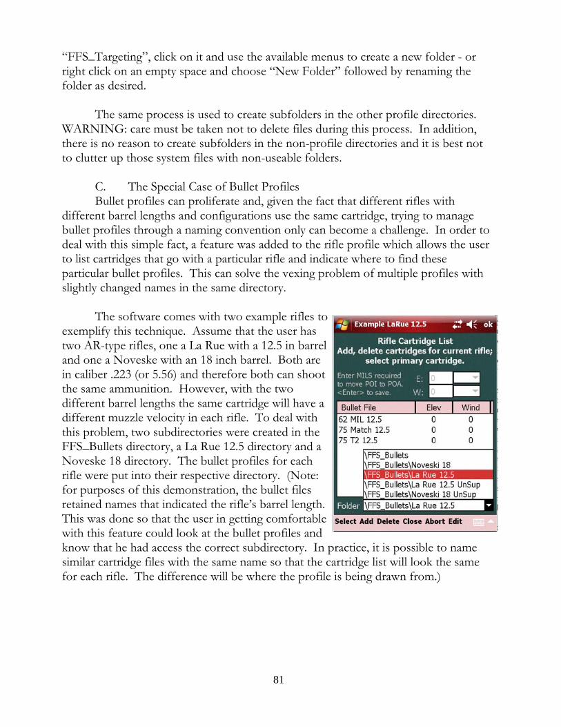
“FFS_Targeting”, click on it and use the available menus to create a new folder - orright click on an empty space and choose “New Folder” followed by renaming thefolder as desired.
The same process is used to create subfolders in the other profile directories. WARNING: care must be taken not to delete files during this process. In addition,there is no reason to create subfolders in the non-profile directories and it is best notto clutter up those system files with non-useable folders.
C. The Special Case of Bullet ProfilesBullet profiles can proliferate and, given the fact that different rifles with
different barrel lengths and configurations use the same cartridge, trying to managebullet profiles through a naming convention only can become a challenge. In order todeal with this simple fact, a feature was added to the rifle profile which allows the userto list cartridges that go with a particular rifle and indicate where to find theseparticular bullet profiles. This can solve the vexing problem of multiple profiles withslightly changed names in the same directory.
The software comes with two example rifles toexemplify this technique. Assume that the user hastwo AR-type rifles, one a La Rue with a 12.5 in barreland one a Noveske with an 18 inch barrel. Both arein caliber .223 (or 5.56) and therefore both can shootthe same ammunition. However, with the twodifferent barrel lengths the same cartridge will have adifferent muzzle velocity in each rifle. To deal withthis problem, two subdirectories were created in theFFS_Bullets directory, a La Rue 12.5 directory and aNoveske 18 directory. The bullet profiles for eachrifle were put into their respective directory. (Note:for purposes of this demonstration, the bullet filesretained names that indicated the rifle’s barrel length. This was done so that the user in getting comfortablewith this feature could look at the bullet profiles andknow that he had access the correct subdirectory. In practice, it is possible to namesimilar cartridge files with the same name so that the cartridge list will look the samefor each rifle. The difference will be where the profile is being drawn from.)
81
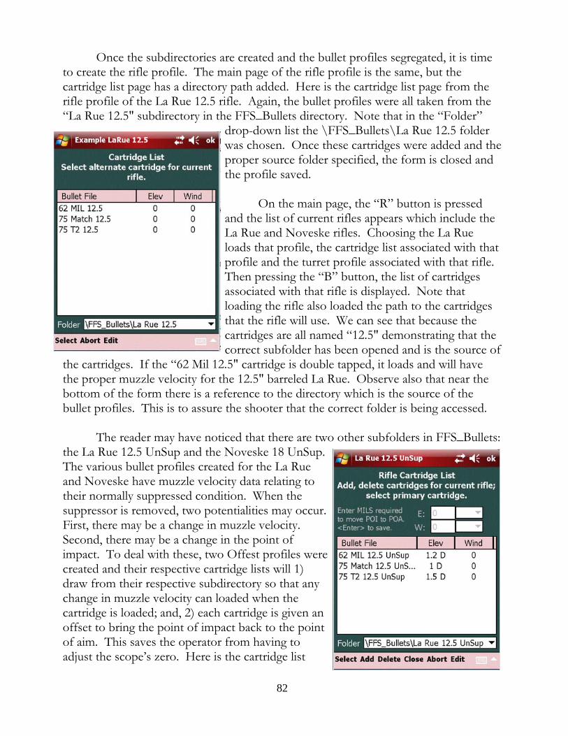
Once the subdirectories are created and the bullet profiles segregated, it is timeto create the rifle profile. The main page of the rifle profile is the same, but thecartridge list page has a directory path added. Here is the cartridge list page from therifle profile of the La Rue 12.5 rifle. Again, the bullet profiles were all taken from the“La Rue 12.5" subdirectory in the FFS_Bullets directory. Note that in the “Folder”
drop-down list the \FFS_Bullets\La Rue 12.5 folderwas chosen. Once these cartridges were added and theproper source folder specified, the form is closed andthe profile saved.
On the main page, the “R” button is pressedand the list of current rifles appears which include theLa Rue and Noveske rifles. Choosing the La Rueloads that profile, the cartridge list associated with thatprofile and the turret profile associated with that rifle. Then pressing the “B” button, the list of cartridgesassociated with that rifle is displayed. Note thatloading the rifle also loaded the path to the cartridgesthat the rifle will use. We can see that because thecartridges are all named “12.5" demonstrating that thecorrect subfolder has been opened and is the source of
the cartridges. If the “62 Mil 12.5" cartridge is double tapped, it loads and will havethe proper muzzle velocity for the 12.5" barreled La Rue. Observe also that near thebottom of the form there is a reference to the directory which is the source of thebullet profiles. This is to assure the shooter that the correct folder is being accessed.
The reader may have noticed that there are two other subfolders in FFS_Bullets:the La Rue 12.5 UnSup and the Noveske 18 UnSup. The various bullet profiles created for the La Rueand Noveske have muzzle velocity data relating totheir normally suppressed condition. When thesuppressor is removed, two potentialities may occur. First, there may be a change in muzzle velocity. Second, there may be a change in the point ofimpact. To deal with these, two Offest profiles werecreated and their respective cartridge lists will 1)draw from their respective subdirectory so that anychange in muzzle velocity can loaded when thecartridge is loaded; and, 2) each cartridge is given anoffset to bring the point of impact back to the pointof aim. This saves the operator from having toadjust the scope’s zero. Here is the cartridge list
82
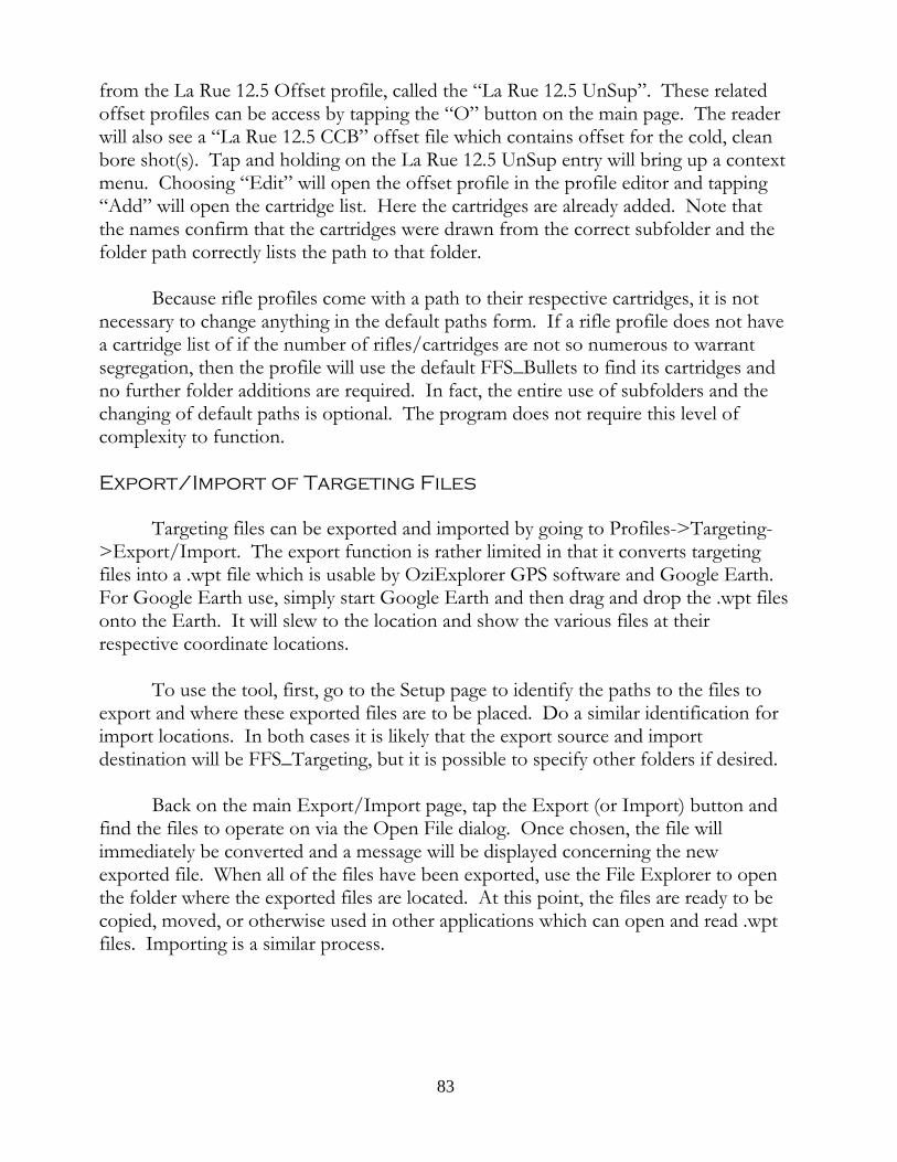
from the La Rue 12.5 Offset profile, called the “La Rue 12.5 UnSup”. These relatedoffset profiles can be access by tapping the “O” button on the main page. The readerwill also see a “La Rue 12.5 CCB” offset file which contains offset for the cold, cleanbore shot(s). Tap and holding on the La Rue 12.5 UnSup entry will bring up a contextmenu. Choosing “Edit” will open the offset profile in the profile editor and tapping“Add” will open the cartridge list. Here the cartridges are already added. Note thatthe names confirm that the cartridges were drawn from the correct subfolder and thefolder path correctly lists the path to that folder.
Because rifle profiles come with a path to their respective cartridges, it is notnecessary to change anything in the default paths form. If a rifle profile does not havea cartridge list of if the number of rifles/cartridges are not so numerous to warrantsegregation, then the profile will use the default FFS_Bullets to find its cartridges andno further folder additions are required. In fact, the entire use of subfolders and thechanging of default paths is optional. The program does not require this level ofcomplexity to function.
Export/Import of Targeting Files
Targeting files can be exported and imported by going to Profiles->Targeting->Export/Import. The export function is rather limited in that it converts targetingfiles into a .wpt file which is usable by OziExplorer GPS software and Google Earth. For Google Earth use, simply start Google Earth and then drag and drop the .wpt filesonto the Earth. It will slew to the location and show the various files at theirrespective coordinate locations.
To use the tool, first, go to the Setup page to identify the paths to the files toexport and where these exported files are to be placed. Do a similar identification forimport locations. In both cases it is likely that the export source and importdestination will be FFS_Targeting, but it is possible to specify other folders if desired.
Back on the main Export/Import page, tap the Export (or Import) button andfind the files to operate on via the Open File dialog. Once chosen, the file willimmediately be converted and a message will be displayed concerning the newexported file. When all of the files have been exported, use the File Explorer to openthe folder where the exported files are located. At this point, the files are ready to becopied, moved, or otherwise used in other applications which can open and read .wptfiles. Importing is a similar process.
83
Using the Expression Calculator
Version 4.8.1.4 introduced an advanced calculator, one that could store userdefined formulas using up to two variables and that could parse expressions. Wherethe expression is comprised of numbers only, the “x” and “y” variable text input areasdo not have meaning or functionality. The arithmetic expression will be parsed andthe result will be given in the answer text area. The value of using an expression parserinstead of the simple calculator is that the entire expression remains on the screen sothe user can see and modify, if necessary, the expression before it is evaluated. Andonce evaluated the expression remains on the screen so that the user can makemodifications if the result does not make sense. For example, 5 + 10 / 5 will produce7 and not 3 as some might suppose. The reason has to do with the precedence ofoperations. In this case, the calculator sees the 5 dividing only the 10 and not the sumof 5 + 10. It is best to use parentheses to clarify the expression: (5 + 10) / 5. This willresolve to the answer 3, i.e., 15/5 = 3. Thus the user can edit the expression instead ofhaving to enter the expression from scratch.
In addition, the calculator can evaluate equations with up to two variables. Example: the hypotenuse of a right triangle can be found by taking the square root ofthe sum of the squares of the other two sides. So if the user were to type into theexpression text area “sqrt( a^2 + b^2)” as a general statement, the user would see thevariables “a” and “b” immediately appear next to the two variable input text areas. There is where the user gives the values for “a” and “b”. If, for example, “a” isassigned the value of 3 and “b” is assigned a value of 4, pressing the “=” key willproduce the answer of 5. The formula remains in the expression area so the user canmake changes or introduce new variable values.
The variable text areas are themselves capable of handling expressions. Thevariable “a” could be “7.3 * sqrt (7)”. Tapping the “Eval” button while the cursorremains in the “a” text area will show what the “a” arithmetic expression evaluates to,in this case 19.3139... It is not necessary to evaluate the variable expression prior touse in the equation, but it is a way to see whether the evaluation makes sense orwhether perhaps a mistake was made. Since the evaluated variable expression replacesthe original expression, in the event of an apparent error, the user will have to re-typethe expression.
A. Storing User Defined FormulasAt the far right of the Expression text area is a drop-down arrow. The software
comes with some example formulas so the user can how to access the formulas thatthe user might make for himself. The formulas themselves are taken from a text filethat can be edited by the user. The existing formulas can be deleted and replaced byformulas that are useful to the user. To access this text file, tap the “Help” menu item
84
and then select “Edit Formulas”. For the first time user, read the text in this file as itexplains how to edit the file. Note that lines that start with the semi-colon symbol areignored by the calculator. These lines are for explaining the purpose or use of aformula or other matter the user wants to memorialize. After the explanation has beread and understood, the user is free to delete the explanation.
Next are the formulas themselves followed by a short explanation that startswith a semi-colon. When the calculator program read through this text file, anyformulas that it finds will be copied to the drop-down menu and the explanation thatfollows will be place immediately below the formula to help the user to rememberwhat the variables are and what units they should be in (if required.) One of theformulas is to compute the cross-wind component of an angling wind. The formula iscross-wind = wind velocity * sin(wind angle relative to shooter), or “w * sin(a)” willproduce the cross-wind component. So, assuming a 7 mph wind from the shooter’s 1o’clock, the formula is w * sin(a) and the variables are w = 7, a = 30 degrees (1 o’clockis 30 degrees, 2 o’clock is 60 degrees, and 3 o’clock is 90 degrees.) Putting those valuesinto the two variable text areas and tapping “=” will yield 3.5 mph in the answer textarea. If the wind speed was 7 m/s or 7 fps, then the answer would be 3.5 m/s or 3.5fps.
There is not a lot of room for the one line explanation of the formula, but in thetext file the user can add as much detail as required. Just make sure that the allexplanatory text begins with a “;”.
85

MiscellaneousTools & Topics
86
Field Zero
In the Options->Tools menu there is a Field Zero item. The form comes withits own explanation which can be accessed using the on form Help menu. Insummary, the field zero function enables a user to verify a previously set zero using arange that is shorter than the zero range. This is a common problem for anyone whoarrives in an area of operations after transport of the rifle system and finds that thelocal area does not permit marking off enough range to verify that the rifle’s zero hasnot changed. The Field Zero tool allows the use of a shorter range and predicts wherethe bullet strike should be, relative to the point of aim, given a specific zero. So, if arifle is zeroed at 500 yards but the user has only 75 yards to check the zero, dependingupon the exact atmospheric conditions, the round should be hitting around 9 inchesabove the point of aim (Federal 308 Match) to reach a zero point at 500 yards. While itwould clearly be better to check the zero at the zero range, where that is not possible afield zero is the next best thing. The Field Zero form can also be used to change thescope’s current zero range to a new range. Just change the “Zero Range” and see whatthe point of impact should be for that zero range, adjust the scope until the bullet ishitting that spot. The scope has effectively been re-zeroed to a different range.
Fixed Zero
A related subject to the Field Zero discussion above is the concept of a fixedscope zero. In the physical world when a rifle is zeroed, it is zeroed in certainatmospheric conditions which dictate the trajectory and influence the muzzle velocityof the projectile. At some later time and in another location, the conditions might bevery different, but the scope is set up for the earlier conditions. Where is the zero?
Assume that a rifle system shooting Federal 308 Match ammunition was zeroedat 700 yards on an standard ICAO day . The next day the rifle and shooter aretransported to a location with an altitude of 5000 ft. The temperature is 75 degrees Fand the station pressure is 23.6 in. Hg.. Where is the zero? The relationship betweenthe rifle and the scope has not changed, but the trajectory at 5000 feet is going to beflatter than it was at sea level. In fact, with the scope set for 700 yards at sea level, at5000 feet and 75 degrees F the bullet will be impacting the target 1.1 MOA high at 700yards. The actual zero has changed to approximately 733 yards.
It is possible to use this program to account for this change without having tore-zero the rifle. When the zero is first obtained, the user can “fix the zero” by 1)insuring that all of the atmospheric and bullet conditions are entered into the computerand then checking the “Fixed Scope Zero” box in the turret profiler. (In this caseenter a standard ICAO atmosphere, use a Federal 308 Match cartridge and assume a
87
muzzle velocity of 2600 fps.) The program no longer assumes a constant zero of 700yards (which requires a constantly changing or floating reticle to match changingconditions) but assumes a fixed reticle and allows the zero range to change based uponcurrent conditions. The zero range is allowed to change as conditions change; thescope’s setting is fixed.
At sea level the above scope zeroed at 700 yards will require an additional 12.4MOA to get to 900 yards. At the new location of 5000 feet ASL, a scope zeroed for700 yards under standard 5000 foot conditions will require only 10.3 MOA to get from700 yards to 900 yards. But a scope zeroed at sea level conditions for 700 yards andthen taken to 5000 feet (using the atmospheric data above) and without changing thezero would require only an additional 9.3 MOA to get to 900 yards. The reason why isthat the scope zeroed at sea level but fired at 5000 feet is now shooting 1.1 MOA highat 700 yards. Because of the elevated impact point it takes fewer MOA to get to 900yards.
When a rifle has changed locations, the user may either re-zero his scope orkeep his sea level zero and check the “Fixed Zero” box and allow the program tocalculate the turret settings under these new atmospheric conditions. The advantage ofnot having to re-zero with every change of location is obvious. The program will makethe adjustments and give the proper elevation if the user has “fixed the zero” for theoriginal conditions under which the rifle and scope were zeroed.
Note that the benefit of a fixed zero disappears for close zeros. The differencebetween points of impact for a 100 yard zero at sea level and a 5000 foot 100 yard zerois 0.022" or 0.021 MOA (for .308 Win. match ammunition). For all purposes, that zerois not materially different. If the user uses close zeros under 200 yards or, perhaps,even 250 yards, he need not be concerned with shifting zeros in changing conditions. A rifle zeroed at 300 yards, on the other hand, will see a zero shift in POI of nearly3/4", a quarter of an MOA, and perhaps enough to justify the “Fixed Zero” option. The user is encouraged to experiment to see what changes may occur given hisparticular zero preference. Remember, these figures are only valid for .308 Win. matchammunition. Different calibers/cartridges will yield different results and flat shootingcartridges may not have significantly changed zeros out to as far as 400 yards.
The Log Button
The log function allows a user to record all pertinent data concerning a shotwith a single click of the “Log” button. The button is by default inactive to avoidhitting it inadvertently and logging unwanted data. To activate the Log button, go tothe Options->Tools menu and choose “Log Enable”. The Log key, previously grayedout, becomes active.
88
Pressing the button will record the date and time, the current location inLat/Lon, UTM or MGRS coordinates (depending upon your preference as revealed onthe Map Ranging page), the pertinent atmospheric conditions and the calculatedelevation and windage among other data items. The log entry also keeps a runningcount of each shot fired. The size of the log is limited only by the memory of thePDA.
The log file can be edited and can be saved under another name. This is a “txt”file and may be opened in Notepad on the desktop computer for easier editing or maybe edited on the PDA by just tapping on the file. The program has a Log Editor(Options menu, Tools, then choose “Log Editor” and open the “CurrentLogData”file) which may be used as well. All current log data is recorded to a default file called“CurrentLogData” and if the program doesn’t find a file by that name it will createone. Each log entry has a line for remarks so the user can add comments ordocumentation for any particular shot taken at some later time.
When the Log button is enabled, it is possible to call up the Log Editor bysimply tapping and holding the Log Button for one-half second. When the editing iscomplete, be sure to Save the changes and close.
By default the log entries are in reverse chronological order, the last event is atthe top of the file. Using the Edit menu item it is possible to change the default tohave the last entry place at the end of the file by unchecking the “Reverse Chron”. Inaddition, if the user has been keeping a log in one order, using the but wishes tochange the default, tapping the “Reverse Entries” Edit menu item will reverse allcurrent entries. Once the entries are in the order desired, tap the “Save” menu item tosave the file.
The PS Button
The PS button stands for “Profile Summary” and is a fast way to check whatbasic data is being used by the program including the atmospheric data, bullet data,which turret is currently being employed and data related to the Coriolis correctionmagnetic variation. It’s function is merely to quickly inform. In addition, the PS formcontains useful reference formulas, conversion factors and convenient menu access tothe calculator.
An interesting value displayed is the “Stability Factor.” The gyroscopic stabilityfactor is a value that shows how stable a bullet is as it exits the muzzle. The stabilityfactor must be at least 1.0 or the bullet probably will not stabilize thereafter; it will spinout of control, tumble, and generally fail to generate a useable trajectory. Generally, atnormal ICAO or Metro conditions, a stability factor of around 1.5 is a decent value.
89
However, it is not uncommon to see stability factors of 1.2 to 2.5 or even higher. Thefactor is, therefore, a function of the density of the atmosphere and as the density thinsin warmer temperatures or higher altitudes, the stability factor will become larger.
The stability factor not only is affected by the atmosphere, it is also a functionof the barrel twist rate and various attributes of the bullet including its mass, diameterand length. As the stability factor increases, the angle of repose also increases whichmeans that the spin drift increases. The stability factor is therefore presented for tworeasons: first, it allows the user to quickly check to make sure that bullet is stabileunder current conditions; second, the user can assess the magnitude of the stabilityfactor and therefore get an idea as to spin drift changes. In the program, the stabilityfactor is actually used to compute spin drift if enough information is supplied by theuser concerning the bullet. On the other hand, if the bullet length is set at “0", thestability factor cannot be computed and a generalized spin drift formula is used.
Unit Conversion
The PS Button also serves to bring up an interactive Unit Conversion page. Tocall up the unit converter, press and hold the PS Button for one-half second. Ofcourse, various unit conversion formulas and well as formulas of general interest arefound on tabs in the PS page. The user therefore has a number of tools available tosolve most problems given the PS page, the unit converter and the field calculator.
Bullet/Cartridge Databases
The last two items on the “Profiles” menu are the Bullet and CartridgeDatabases. These are generally informational and based upon publically available data. The muzzle velocities shown for manufactured cartridges are as published by themaker and may or may not have relevance to the shooter in his rifle. Both databasescan be filtered for a particular caliber, weight, manufacturer, etc. To choose thefiltering criteria, highlight a selection (click once on the Maker) and then tap the headerof the column for the parameter of interest. For example, if the user was interested inseeing only Berger bullets of the .30 caliber size in the Bullet Database, scroll down tothe Berger bullets, highlight any Berger bullet that lists .308 as the bullet diameter, thentap on the Maker header and the Diameter header, and tap the “Load Selected BulletData” button. Only Berger bullets of the .308 caliber variety will be shown.
The data in the Bullet Database can be automatically inserted in a Bullet Profilemerely by double-clicking on the “Maker” for the bullet of interest. The database willautomatically close and the data will be inserted in the profile ready to be completed bythe shooter and saved.
90
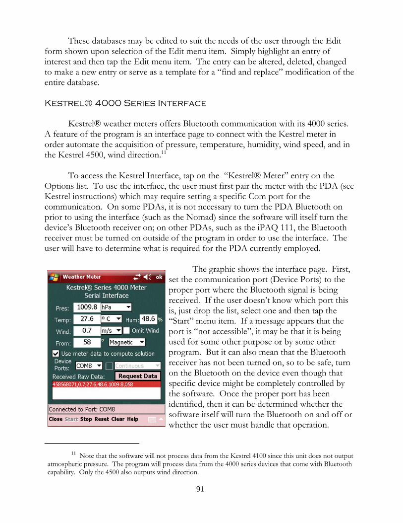
These databases may be edited to suit the needs of the user through the Editform shown upon selection of the Edit menu item. Simply highlight an entry ofinterest and then tap the Edit menu item. The entry can be altered, deleted, changedto make a new entry or serve as a template for a “find and replace” modification of theentire database.
Kestrel® 4000 Series Interface
Kestrel® weather meters offers Bluetooth communication with its 4000 series. A feature of the program is an interface page to connect with the Kestrel meter inorder automate the acquisition of pressure, temperature, humidity, wind speed, and inthe Kestrel 4500, wind direction.11
To access the Kestrel Interface, tap on the “Kestrel® Meter” entry on theOptions list. To use the interface, the user must first pair the meter with the PDA (seeKestrel instructions) which may require setting a specific Com port for thecommunication. On some PDAs, it is not necessary to turn the PDA Bluetooth onprior to using the interface (such as the Nomad) since the software will itself turn thedevice’s Bluetooth receiver on; on other PDAs, such as the iPAQ 111, the Bluetoothreceiver must be turned on outside of the program in order to use the interface. Theuser will have to determine what is required for the PDA currently employed.
The graphic shows the interface page. First,set the communication port (Device Ports) to theproper port where the Bluetooth signal is beingreceived. If the user doesn’t know which port thisis, just drop the list, select one and then tap the“Start” menu item. If a message appears that theport is “not accessible”, it may be that it is beingused for some other purpose or by some otherprogram. But it can also mean that the Bluetoothreceiver has not been turned on, so to be safe, turnon the Bluetooth on the device even though thatspecific device might be completely controlled bythe software. Once the proper port has beenidentified, then it can be determined whether thesoftware itself will turn the Bluetooth on and off orwhether the user must handle that operation.
11 Note that the software will not process data from the Kestrel 4100 since this unit does not outputatmospheric pressure. The program will process data from the 4000 series devices that come with Bluetoothcapability. Only the 4500 also outputs wind direction.
91
Once the correct port has been identified and the Bluetooth receiver of the device hasbeen turned on, pressing the “Start” menu item will open the port and begin thecommunication with the Kestrel device. The graphic to the left shows the page oncecommunication has been established. There are a few things to note here: First, theKestrel meter does not include the units in its data sent to the PDA. The raw data isshown in the Received Raw Data display area and has the following format: thenumber of seconds since 1 January 2000, wind speed, temperature, humidity, pressure,wind direction. Note carefully that the units of each value is not included. Therefore,it is critically important that the user set the units on the interface page to mirrorthose he has set on the Kestrel device. If the units are mismatched, the programwill become incredibly confused. For instance, the current pressure is 29.69 in. Hg.which is equivalent to 1005.42 hPa. If the user had failed to indicate that the unitswere “in. Hg.” but instead left them in “hPa”, the program would use 29.69 hPa, whichis equivalent to 0.877 in. Hg, nearly a vacuum. Trajectories would be incredibly flat -and completely erroneous. So, be sure to set the units to mirror those in the Kestrel.
Of special note is the wind direction. Here the wind direction is shown as 58degrees, almost due East. Remember that wind direction is always referenced by thesource of the wind, i.e. the direction it is coming from. Second, note that this directionis identified as “Magnetic”. This is because the declination value in the Kestrel unit isset to 0 degrees and the value is uncorrected and thus the direction as reported by themagnetic compass. If the user had, for some reason, set the declination to the localvalue, the user would have also set the wind direction reference at “True” because thedeclination will correct the magnetic compass value to the true North reference.12
Once the connection has been established, the user can update the values on theinterface page by either tapping the “Request Data” button or by pressing the Enterbutton on the face of the device. The user will note also that the “Kill” menu item haschanged to “Close” permitting the closure of the interface page without closing theserial port; the data will continue to be received when requested.
Upon “Closing” the interface page the user will note that the wind speed anddirection data areas on the main page have turned a slightly darker background color. This is a visual cue to the user that the Kestrel unit is connected and the port is open. The windage data can be updated by pressing the Enter button on the PDA control
12 The program uses the term “magnetic variation” to describe the local value that must be added toor subtracted from the compass value to yield a “True” direction whereas the device documentation uses theterm “declination”. Declination has two components: the magnetic variation (the difference between trueNorth and magnetic North from the current location) plus magnetic deviation (any local cause of magneticdeflection such as high tension wires, electronic equipment, or a magnetic source in the immediate vicinity. The software does not deal with magnetic deviation; the program gives the user, for any given position onEarth, the magnetic variation for that position. Hence the difference in terminology.
92
panel. Likewise, going to the Presets page the user will note that the Pressure,Temperature and Humidity data areas are the same darker background color to visuallycue the user. Those data areas can also be updated by pushing the Enter button whilein the Presets page. The same is true on the Target Range Card as it relates to the windspeed and direction data items.13
This particular port is used to transmit requests to the Kestrel unit and receivethe information in reply. When “Stop[ping]” the data and then re-“Start[ing]” theconnection, allow a couple of seconds to permit the operating system to properly clearthe port and open it. Don’t get in a hurry as it will provoke a “port not accessible”error message. If that message appears, tap the “Reset” menu item a couple of timesand try to open the connection again. If the message persists, check the Kestrel unit tomake sure it is still on. It may have shut off automatically.
Continuous OperationLooking back at the interface page, with the connection “Stop[ped]” or “Reset”,
the check box related to the “Continuous” drop down box becomes enabled. Checking the check box enables the “Continuous” drop down box allowing the user tochoose various update time intervals. The default is two seconds and the user canchoose an interval up to every 1 minute.
Two considerations when using the Continuous mode: first, as long as therequests for data from the Kestrel unit is continuously occurring, the battery is beingdrained on both units. Second, continuous operations interferes with other displayareas, such as the Elevation Table. With each refresh of the data and new computationof the firing solution, the Elevation Table is redrawn and the data presented in itsdefault format. So, if the user is looking at the time of flight column when the requestfor Kestrel data occurs, the user will see the TOF column disappear replaced withupdated computations as if the the “Refreash” menu item had been pressed. Theeffect is basically the same: with each update of Kestrel data, the state of the datathroughout the program’s environment is “refreshed” and set back to default.
Updating Delta V Software
A. Versions 4.7 and EarlierEach of these program has a unique “fingerprint” which manifests itself through
a set of data that must be reproduced by the user in order to purchase updates. Updates are obtained via the Lex Talus Corporation’s website by choosing the update
13 Not shown on the Kestrel graphics is the addition of a “Omit Wind” check box in version 4.8.1.5. Checking this box will allow the Kestrel data to refresh the pressure, temperature, and humidity but will notaffect the wind value or direction in the main program.
93
required and proceeding through the purchase process. In the initial window whichdisplays the shopping cart, there is a text area for the user to input the required data sothat Lex Talus can create the updated software for the user that will be compatiblewith the SD card the user already owns. At the time of purchase, Lex Talus salesdepartment receives a notice of sale which includes the unique data from the user, usesthis data to create the necessary software and emails the updated software to the user. The updated software is installed on the SD card via an updating/installer programthat runs on a Windows desktop computer and automates the updating process. Atthe conclusion of running the updating program, the update is complete.
In order for the user to obtain the necessary program information, open theOptions->About->Program Info form and click on the “Get Program Identifiers”button. This creates a text file (the content of which is shown in the text window onthe form) which is saved in the \Documents directory of the SD card. Simply copythe text file to the desktop computer, open the file and copy the content, and thenpaste it into the text window of the shopping cart during the purchase process. Alternatively, complete the update purchase and email the text file to Lex Talus sales([email protected]) notifying Lex Talus of the purchase and relating the data to thepurchase. In this case, it would be prudent to indicate in the shopping cart text formthat the program data is being sent separately via email.
B. Version 4.8With version 4.8 an effort was made to make the update process much easier.
For version 4.8 installed software the update process consists of merely checking thewebsite’s Delta V page and noting the current update version number. A link isprovided on that page to download the instructions for update and the instructionscontain a link to a download site. Download the current version and install inaccordance with the instructions. The program identifiers mentioned in the precedingparagraph are still important and may be crucial is something happens to the license onthe card. Therefore, it is a good idea for the user to create the program identifier textfile and save it as a backup on some other computer.
94
Appendix 1
Troubleshooting
95
Setup and Troubleshooting for the Trimble Nomad but Generally Applicable to Other PDAs as Well
The first thing you must do with a new Nomad is to “calibrate” the battery. This willtake the better part of a day. Once calibrated, insert the Delta card into the SD drivewhich is located under the black cap at the top of the unit. Remove the black cap withthe Phillips end of the stylus by turning each screw ½ turn counter-clockwise. Thescrews will pop up signaling that the top may be lifted off. The SD drive slot will belocated on the left of the now exposed cavity.
Pairing a Kestrel
1. Turn the Kestrel on. Go to the setup menu and click on the second line,Bluetooth. Turn on the Bluetooth transmitter then click “Info” and make note ofthe four digit PIN number. Leave the Kestrel on.
2. Turn on the Nomad. Click Start->Settings->Connections->Bluetooth. Tap onthe “Add new device.” The Nomad will search for Bluetooth devices in the areaand find the Kestrel. Highlight the Kestrel entry and hit Next on the menu. Enter the PIN and click Next.
3. Once the connection has been made you will be taken back to the first pagewhere there are five tabs at the bottom of the page. Click on “COM Ports” andtap “New Outgoing Port”. Select a port (port 8 or 9) and note this port; you willneed to know it when you first connect the Kestrel to the program.
4. Start the Delta program; tap Options->Kestrel Meter. Once the Kestrelinterface page appears, set the Com Port to that designated during the Bluetoothsetup. Once set, tap on “Start” in the menu and the connection should be made. This should take a few seconds.
5. Be sure to set the units on the interface to those you have set for the Kestreldevice. The data sent by the Kestrel does not include units so the Delta programwill not know whether the pressure is in.Hg. or hPA or whether temperature isdegrees Celsius or Fahrenheit.
Problems with Setting Outgoing Com Ports
After you have assigned a Bluetooth device to an outgoing com port and decide tochange that com port to another device, you may find that you are unable to do so andeach time you try you get an error message: “The COM port could not be created.
96
Please check your settings and try again.” The problem is not the settings; the problemis that you can’t delete an existing assignment and even if you delete the device from thedevices list, it still does not free up the port for reassignment. This is a bug in theoperating system.
There are two ways to solve the problem. The first is to do a hard reset. When you doa hard reset, all of the entries in the system’s registry are deleted and the registry isrebuilt as if new. The Bluetooth com port assignments are recorded in the registry sorebuilding the registry deletes these assignments and makes the com ports availableonce again. After the hard reset, when the computer comes back on line you will seethat you have no trouble assigning the com ports as you wish.
The second approach avoids the hard reset and attacks the problem directly by goinginto the registry and deleting the subkeys that are blocking the reassignment. This is foradvanced computer users so if you didn’t understand the preceding sentence, youprobably are better off doing the hard reset.
If you can handle making registry changes, then you will need to acquire a windowsmobile registry editor. You connect your Nomad to your desktop computer and runthe windows mobile registry editor from the desktop. This program will display theregistry on the Nomad and allow you to inspect individual entries. Open the followingkey in the HKEY_LOCAL_MACHINE hive:
Software\Microsoft\Bluetooth\Serial\Ports\
You should see one or two subkeys with cryptic names like "0000000d88ace93e". Delete all of the subkeys. These keys are created when you make an assignment of acom port to a specific device and are blocking you from assigning new devices to theport.
With the keys deleted, you should have no trouble assigning the com ports are you seefit.
Connecting with the Internal GPS
First you need to set up the operating system to use the internal GPS of the Nomadmost efficiently. To do this, turn on the Nomad, tap on the Start menu in the upperleft-hand corner, then tap Settings->System->GPS. On the GPS page you will see fourtabs: Program, Hardware, Access, A-GPS. Enter these settings: Program - Com3;Hardware - Com2, 9600 Baud; Access - Uncheck the “Manage GPS automatically”; A-
97
GPS - Uncheck “Enable Assisted GPS”.
Generally, if the Nomad is in its original default state, starting the GPS in the programresults in the immediate transfer of data. Go to Ranging->GPS and tap Start in themenu. If you tap the Devices tab you will see the data being transmitted by the GPS.
The Nomad comes with a program called SatViewer that when opened for some reasonredirects the signal to a location that the Delta program can’t find. If you have openedthe SatViewer program, you will probably need to reset the Nomad unit back to defaultstatus. To do that:1. Exit the Delta software.2. Press and hold the Nomad power button. When you see the “5 Second!”
warning, release the power button and tap the “Shutdown” button. Aftershutdown, wait for 10 minutes.
3. Power up the Nomad by pressing the power button. At this point, all internalsettings for the Nomad should be returned to default and the Delta softwareshould easily connect to the GPS.
In the event that the Nomad is still unable to connect to its GPS receiver, or if it isconnected but is not receiving Satellite information, then it is necessary to reset the GPSchip itself to its default settings.
To reset the GPS chip back to its default state, shutdown the computer and remove thebattery from the device for about 5 minutes. This will cut off the power to the GPSchip, which will cause it to reset back to its default state. Removing the battery is anessential step, as performing the Shutdown step does not affect the GPS chip itself.
To ensure that there is no risk for data loss, always close all active programs andproperly shutdown the computer before removing the battery.
Transferring Files Between Nomads
One of the conveniences of the software is the ability to share profiles with others. Transferring a file between two Nomads in the field is relatively simple.1. The Receiving Nomad must
a. Tap Start->Settings->Connections->Beams and check the “Receive allincoming beams” box. Hit OK.
b. Tap Bluetooth-Mode tab and check “Turn on Bluetooth” and “Make thisdevice visible”. Tap OK.
2. To make it easier to identity the Receiving Nomad, tap the System tab, then
98
About->Device ID tab. Change the Device Name to something descriptive. Tab OK, X and you should be back to the main screen.
3. On the Sending Nomad, tap and hold on the file to send. On the appearingcontext menu tap “Beam File”. The Nomad will search for local Bluetoothdevices and list same which hopefully will include the Receiving Nomad. Tap onthe Receiving Nomad and the file will be sent.
4. On the Receiving Nomad, the file will be found in the \My Documents folder ofthe PDA. Tap and hold on the file, hit “Cut” (or “Copy”) and move to thelocation on the Delta card that the file will go. Tap and hold in the selecteddirectory and “Paste”.
Odd Program Behavior
The program saves its state when you shut it down so that when you start the programlater it can pick up exactly where you left off. All of the settings and data will bereloaded. Sometimes the program memory space will get corrupted for one reason oranother and when that happens, merely cycling the program on and off will not help;when the program is turned off, this corrupt state is saved and when the program isstarted again, the corrupt state is reloaded.
To rid the program of a corrupt data item:1. Go to Options->Tools and click on the Reset Program menu item. At this
point, the file that keeps track of the program state is cleared.2. With the program still running, press and hold the Nomad power button. When
you see the “5 Second!” warning, release the power button and tap the“Shutdown” button. After shutdown, wait for 10 minutes.
3. Remove the Delta SD card from the Nomad.4. Power up the Nomad by pressing the power button. At this point, the memory
space of the Nomad is clear of any residual program data. Reinsert the Deltacard. It will start with its original default values.
5. Carefully reload the profiles you were using. Pay close attention to the program’soperation after each profile is loaded. If after loading a particular profile youbegin to see odd behavior again, you can suspect that the profile in questioncontains some bad data that is causing the problem. Open that profile in itseditor, check each data item, and re-save. If the problem persists, contactSupport.
99

Appendix 2
Videos - Title Listing
100
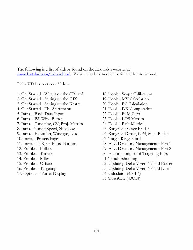
The following is a list of videos found on the Lex Talus website atwww.lextalus.com/videos.html. View the videos in conjunction with this manual.
Delta V© Instructional Videos
1. Get Started - What's on the SD card 2. Get Started - Setting up the GPS3. Get Started - Setting up the Kestrel 4. Get Started - The Start menu5. Intro. - Basic Data Input 6. Intro. - PS, Wind Buttons7. Intro. - Targeting, CV, Proj. Metrics 8. Intro. - Target Speed, Shot Logs9. Intro. - Elevation, Windage, Lead 10. Intro. - Presets Page11. Intro. - T, R, O, B List Buttons 12. Profiles - Bullets13. Profiles - Turrets 14. Profiles - Rifles15. Profiles - Offsets 16. Profiles - Targeting17. Options - Turret Display
18. Tools - Scope Calibration19. Tools - MV Calculation 20. Tools - BC Calculation21. Tools - DK Computation 22. Tools - Field Zero23. Tools - LOS Metrics 24. Tools - Path Metrics25. Ranging - Range Finder 26. Ranging -Direct, GPS, Map, Reticle27. Target Range Card 28. Adv. Directory Management - Part 129. Adv. Directory Management - Part 2 30. Export - Import of Targeting Files31. Troubleshooting 32. Updating Delta V ver. 4.7 and Earlier33. Updating Delta V ver. 4.8 and Later 34. Calculator (4.8.1.4)35. TwistCalc (4.8.1.4)
101