Embed Size (px)
Citation preview
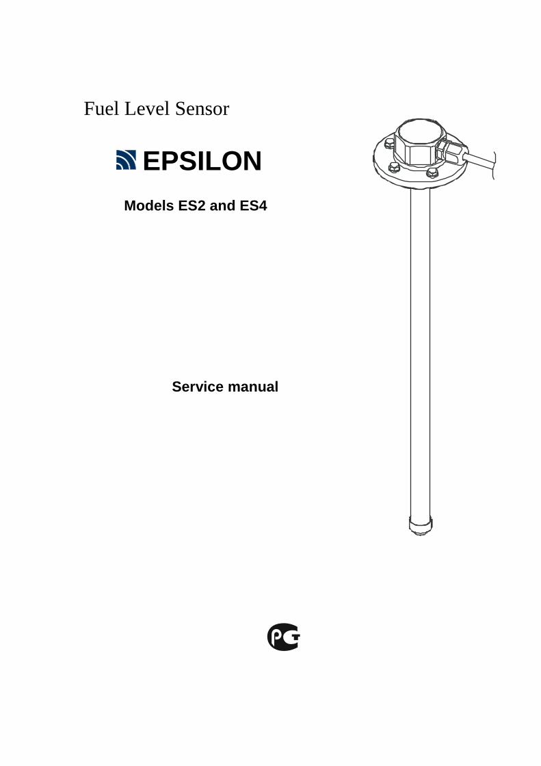
Fuel Level Sensor
EPSILON
Models ES2 and ES4
Service manual
2
Contents
1. USE ................................................................................................................................................... 5
2. EXPLOSION PROTECTION .............................................................................................................. 5
3. MAIN TECHNICAL CHARACTERISTICS ......................................................................................... 6
4. DELIVERY SET .................................................................................................................................. 8
4.1 Main delivery set ..................................................................................................................................... 8
4.2 Extra accessories ............................................................ Ошибка! Закладка не определена.
4.3 Consumables and tools for sensor's installation and calibration ...................................... 8
5. LIST OF DOCUMENTS AND SOFTWARE FOR SENSOR'S INSTALLATION AND CALIBRATION 9
6. LIST OF DEVICES AND EQUIPMENT FOR SENSOR'S INSTALLATION AND CALIBRATION.............. 9
6.1 Instrumentation ...................................................................................................................... 9
6.2 Equipment, tools and consumables .......................................................................................................... 9
7. STRUCTURE AND WORK OF SENSOR ......................................................................................... 10
7.1 Structure of FLS ................................................................................................................... 10
7.2 Work of FLS ....................................................................................................................................................... 11
8. INSTALLATION ............................................................................................................................... 13
8.1 Preparation of fuel tank for sensor's installation ............................................................... 13
8.2 Preparation of sensor for installation ................................................................................. 15 8.2.1 Measuring of probe's length ................................................................................ 15 8.2.2 Changing of probe's length .................................................................................................... 15
8.3 Installation of sensor on fuel tank....................................................................................... 17
8.4 Connection of sensor to control units ................................................................................ 17
8.5 Sealing of sensor ................................................................................................................. 20
9. CALIBRATION .............................................................................................................................. 20
10. MAINTENANCE ............................................................................................................................ 21

EPSILON ES2,ES4
3
11. TRANSPORTATION AND STORAGE ........................................................................................... 23
12. WARRANTY .................................................................................................................................. 23
Appendixes
1 SOFTWARE APPLICATION ES INSTALL ..................................................................................... 24
2 UNIFIED PROTOCOL EPSILON DATA EXCHANGE (EDE). ........................................................... 35
3 MEASURING HEAD MARKING. ...................................................................................................... 46
4 CONNECTION OF SENSORS ES2 AND ES4 TO CONCENTRATOR OF FUEL LEVEL SENSORS
«DALCON» .......................................................................................................................................... 47
5 CONNECTION OF SENSORS ES4 TO ONBOARD MONITORING CONTROLLERS OF
TRANSPORT SERIES «АВТОГРАФ-GSM» ........................................................................................ 48
6 CONNECTION OF SENSORS ES4 TO CONTROL UNIT OF MANAGEMENT SYSTEM OF
TRANSPORT NAVIGATION "TELETRACK" ....................................................................................... 50
7…CONNECTION OF SENSORS ES2 TO TRANSPORT MONITORING APPLIANCE "INTELLITRAC
A1" ....................................................................................................................................................... 51
8 CONNECTION OF SENSORS ES2 TO TRANSPORT MONITORING APPLIANCE TELTONIKA
MF4100(4200) -. .................................................................................................................................... 58
9 Connecting sensors to the subscriber terminal ES2……………………………….……….58 10 Connecting sensors to the subscriber terminal ES2……………………………….……….58

4
Safety requirements on installation and maintenance of fuel level sensor
During installation of the fuel level sensor you should take organizational and technical measures for ensuring safe work with instrumentation, accessories and consumables. Responsibility for the implementation of security measures is imposed to technical personnel that install the fuel level sensor, and to the staff that is responsible for the equipment of place where the work will be performed. At the place of work fire safety rules should be kept in accordance with GOST (Ukrainian: ГОСТ 12.1.004 "ССБТ. Fire Safety. General requirements", and rules of electrical safety in accordance with ГОСТ 12.1.019" ССБТ. Electrical safety. General requirements. " On motor transport at the place of work labour safety rules should be kept in accordance with: ДНАОП 0.00-1.28-97 "Rules of safety on motor transport" (in Ukraine) or ПОТ РM 027-2003 "Inter-sectoral labour safety rules on motor transport» (in Russian Federation).
EPSILON ES2,ES4
5
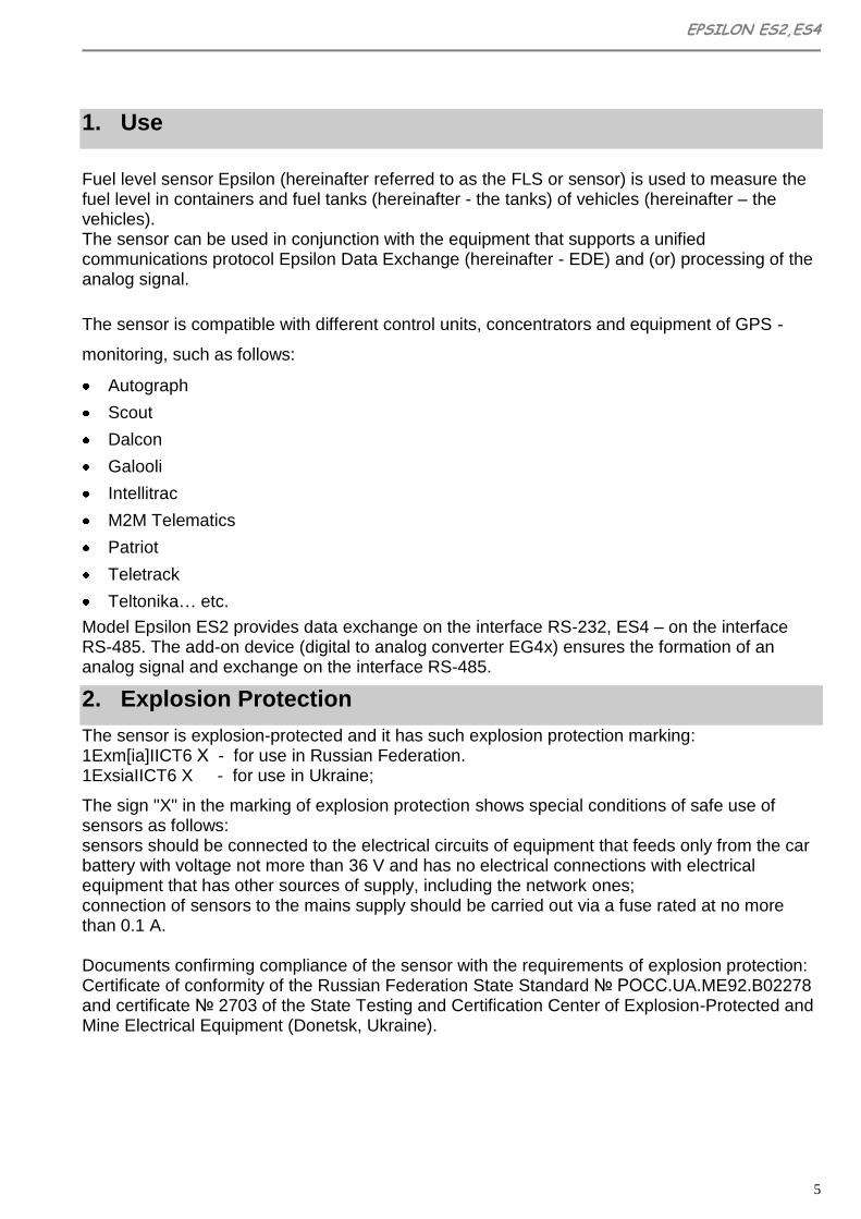
1. Use
Fuel level sensor Epsilon (hereinafter referred to as the FLS or sensor) is used to measure the fuel level in containers and fuel tanks (hereinafter - the tanks) of vehicles (hereinafter – the vehicles). The sensor can be used in conjunction with the equipment that supports a unified communications protocol Epsilon Data Exchange (hereinafter - EDE) and (or) processing of the analog signal.
The sensor is compatible with different control units, concentrators and equipment of GPS -
monitoring, such as follows:
Autograph
Scout
Dalcon
Galooli
Intellitrac
M2M Telematics
Patriot
Teletrack
Teltonika… etc.
Model Epsilon ES2 provides data exchange on the interface RS-232, ES4 – on the interface RS-485. The add-on device (digital to analog converter EG4x) ensures the formation of an analog signal and exchange on the interface RS-485.
2. Explosion Protection
The sensor is explosion-protected and it has such explosion protection marking:
1Exm[ia]IICT6 Х - for use in Russian Federation. 1ExsiaIICT6 X - for use in Ukraine;
The sign "X" in the marking of explosion protection shows special conditions of safe use of sensors as follows: sensors should be connected to the electrical circuits of equipment that feeds only from the car battery with voltage not more than 36 V and has no electrical connections with electrical equipment that has other sources of supply, including the network ones; connection of sensors to the mains supply should be carried out via a fuse rated at no more than 0.1 A. Documents confirming compliance of the sensor with the requirements of explosion protection: Certificate of conformity of the Russian Federation State Standard № РОСС.UA.ME92.B02278 and certificate № 2703 of the State Testing and Certification Center of Explosion-Protected and Mine Electrical Equipment (Donetsk, Ukraine).

6
3. Main Technical Characteristics
Table 1.
Name of characteristic or parameter Units Value Notes
General
Accepted values of electrical conductivity of controlled fuel, not more
Cm/m
10-8 1
Limit range of operating temperature 0С – 40 … + 75
Climatic range 1.1 ГОСТ15150-69
Degree of protection IP56
Measurement
Range of measured values of level of controlled fuel
mm
from 10 to 800
2,3,4 from 800 to 3000
Resolution of measurement of diesel fuel level in static mode, not worse
mm 0,05 5
Basic permissible error in level measuring in static mode, no more
mm 0,5 6
The period of measurement results averaging in a dynamic mode
s 8
Bit code representation of measurement results
bit 10/12/16 Level (8)
8 Temperature
Supply
Voltage supply, operating range V +8 -10% ÷ +36 +20%
Rated
Current consumption мА 5,5±0,5 with 12V
2,5±0,2 with 24V
Operating mode Long-term
Permissible effect of pulsed voltage supply to circuits
+ 160В, 1с
-1000V 8
Interface
Digital RS-485 Model ES4
RS-232 Model ES2
Analog (using a digital-analog converters EG-41 (8 bits) EG-42 (12 bits)
мВ
25…3175 9
25…4000 9
Accession size, weight
EPSILON ES2,ES4
7
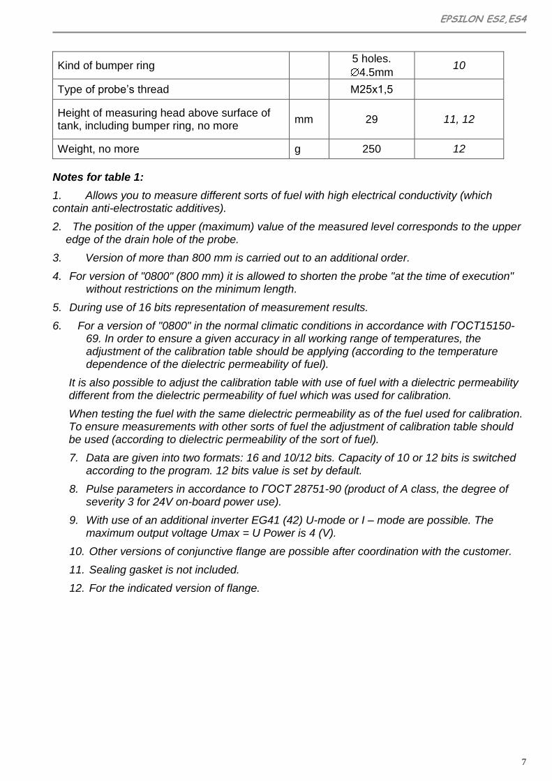
Kind of bumper ring 5 holes.
4.5mm 10
Type of probe’s thread M25х1,5
Height of measuring head above surface of tank, including bumper ring, no more
mm 29 11, 12
Weight, no more g 250 12
Notes for table 1:
1. Allows you to measure different sorts of fuel with high electrical conductivity (which contain anti-electrostatic additives).
2. The position of the upper (maximum) value of the measured level corresponds to the upper edge of the drain hole of the probe.
3. Version of more than 800 mm is carried out to an additional order.
4. For version of "0800" (800 mm) it is allowed to shorten the probe "at the time of execution" without restrictions on the minimum length.
5. During use of 16 bits representation of measurement results.
6. For a version of "0800" in the normal climatic conditions in accordance with ГОСТ15150-69. In order to ensure a given accuracy in all working range of temperatures, the adjustment of the calibration table should be applying (according to the temperature dependence of the dielectric permeability of fuel).
It is also possible to adjust the calibration table with use of fuel with a dielectric permeability different from the dielectric permeability of fuel which was used for calibration.
When testing the fuel with the same dielectric permeability as of the fuel used for calibration. To ensure measurements with other sorts of fuel the adjustment of calibration table should be used (according to dielectric permeability of the sort of fuel).
7. Data are given into two formats: 16 and 10/12 bits. Capacity of 10 or 12 bits is switched according to the program. 12 bits value is set by default.
8. Pulse parameters in accordance to ГОСТ 28751-90 (product of A class, the degree of severity 3 for 24V on-board power use).
9. With use of an additional inverter EG41 (42) U-mode or I – mode are possible. The maximum output voltage Umax = U Power is 4 (V).
10. Other versions of conjunctive flange are possible after coordination with the customer.
11. Sealing gasket is not included.
12. For the indicated version of flange.

8
4. Delivery set
4.1 Main delivery set
Table.2
Name Decimal number Quantity Notes
1 Measuring head ES.100 1
2 Probe ES.200 1
3 Connecting cable ES.300 1
4 Flange ES.001 1
5 Cap ES.002 1
6 Self-drilling screw ES.004 1 With a hole for sealing
7 Self-drilling screw 9Т64219-2 4
8 Gasket 5320-382713 1
9 Passport ES.402 ПС 1
10 Indicator’s seal SILTECH 2 With wire for sealing
11 ZIP String 1
4.2 Extra Accessories
Table 3.
Name Decimal number Notes
1) Service manual ES.401 RE
2) Compact disk CD-R ES.000 CD1 With program "eS Install" for sensor’s setting
3) Cap М25х1.5 Installed on the tank after removal of the sensor
4) Plug IEC ES.002.0 Installed on the tank after removal of measuring head
5) Fuse 0,1А 250V Ø5х20 mm, high-speed

EPSILON ES2,ES4
9
4.3 Сonsumables and tools for sensor’s installation and calibration
Consumables and tools for sensor’s installation and calibration can be supplied on special request (see section 6).
5. LIST OF DOCUMENTS AND SOFTWARE FOR SENSOR’S
INSTALLATION AND CALIBRATION
● Passport ES.402 ПС.
● Service manual* ES.401 РЭ.
● User’s software on CD disk** ES.000 CD1
* - 1 manual with 10 sensors is supplied
** - supplied on special request
6. LIST OF DEVICES AND EQUIPMENT FOR SENSOR’S
INSTALLATION AND CALIBRATION
6.1 Instrumentation Table.4
Name Quantity
1) Multimeter M890G 1
2) Tape measure 3 m 1
3) Measuring cup or flow meter, providing measuring errors of fuel volume not worse than ± 0,1%
1
6.2 Equipment, tools and consumables Table.5
Name Quantity
1) Metal cutting tool for holes making Ø22 ± 0,5 mm in the sheet material of the tank surface. Preferably produced by RUKO:
a. For hydraulic hole punching: a set 5 hydraulic, article 109 009,
b. For drilling: carbide crown drill Ø22, article 105 022.
1 set
2) Electric drill with holder of clamping of the tool shank with diameter NLT 10 mm.
1
3) The network extender in polyurethane insulation, 220V, 4А. 1
4) Pipe cutter is used when necessary to reduce the length of the 1

10
probe (preferably produced by ROTHENBERGER company: "MINIKAT II PRO", Art. 7.0402 or similar).
5) Spanner with 7 mm gap amount. 1
6) Spanner with 36 mm gap amount (can be ordered at your sensor provider). Note for order IEC ES.002.0.
1
7) Special spanner for probe (can be ordered at your sensor supplier). Note for order IEC ES.003.0.
1
8) Auto Sealant Loctite 5900. 0,1 ml
9) Laptop (PC), minimum requirements: Pentium 500 MHz, 64 MB RAM, MS Windows 98/2000/XP, MS Office not higher than 2003, not less than 10MB of free hard disk space, the manipulator "mouse", a free USB-port.
1
10) Adapter for connecting of the sensor eS2 to the PC 1
11) The converter USB/RS-485 model MOXA UPort 1130 (for calibration of the tank with the sensor eS4).
1
12) The converter USB/RS-232 model MOXA UPort 1110 (for the calibration of the tank with the sensor eS2).
1
7. Structure and work of sensor
7.1 Structure of FLS
The measuring head of the sensor (Pic. 7.1) consists of a level converter, a digital circuit of signal processing, the device of data exchange, the voltage balancer and circuit which provides necessary protection for input and output circuits.
Connection to external devices is providing with help of interface cable.

EPSILON ES2,ES4
11
Pic. 7.1 The general view of the “Epsilon” FLS
Measuring of fuel level is made with help of measuring head with the probe, immersed into the fuel. The probe is a coaxial capacitor, which is made of an aluminum tube (external electrode) and insulated copper string (internal electrode). The required tension of the string is supported by a spring which is situated in contact of the probe’s connector.
Mounting of the sensor is performed with help of self-drilling screws, which fix the sensor’s flange on the tank. Impermeability of the fit of measuring head is provided by sealing ring, located in the front groove.
The interface cable is protected from mechanical damage by a flexible metal sleeve or corrugated pipe.
The sensor safety is provided by such facilities:
fuse for protection against overloads and short circuits;
intrinsically safe measuring circuit with normalized values of voltage, inductance, capacitance and resistance;
multi-level protection of charging and interface circuits;
metal sheath with a proper degree of protection (IP56 according to ГОСТ14254);
compound filling of the measuring head’s membrane.
7.2 Work of FLS
The sensor’s probe during the immersing into fuel perform the function of a variable capacitor whose capacitance linearly depends on the level of it’s filling by fuel.
The measuring head of the sensor performs a linear transformation of the probe’s capacitance to digital code of fuel level, the processing of received digital data with averaging of measurement results, taking the temperature of the fuel tank and delivery of the data in a
Measurement head
Hermetic cable input
Interface cable
Sealing rubber ring
Flange
Gasket
Zonde
Plug
Cap of Plug

12
unified protocol EDE of bus RS- 485 or RS-232 or in an analog signal (only the level), depending on the model.
Data about fuel level may be issued in the form of 10-, 12-or 16-bits value, the temperature data - in the form of 8-bits value.
For determination of the amount of controlled fuel the procedure of calibration of fuel tank should be carried out. During this procedure the dependence between the amount of fuel and its level, measured by sensor (by the code of the level), is set.
Controlling of the calibration procedure and setting of parameters of data exchange with the help of eS Install program are described in details in Appendix 1.
Protocol of data exchange EDE is shown in Appendix 3.

EPSILON ES2,ES4
13
8. Installation
8.1 Preparation of fuel tank for sensor’s installation
The sensor is installed in the center of the fuel tank, as shown on Pic 8.1.
Only in this case, when vehicle is inclined, during acceleration or deceleration the fuel level at the measuring point is the least volatile for fluctuations. The measuring probe should be set vertically down. Improper installation of the probe may be the reason of accuracy loss in determining of fuel amount.
If the top of tank is difficult to access, it is necessary to remove the tank from the vehicle for proper installation of the sensor.
.
Pic. 8.1 Proper position of sensor on fuel tank
It is necessary to clean the fuel tank in the place of sensor’s installation.
!
WARNING! Before sensor’s installation on the tank, firstly you should fill it with water or drain fuel and oil lubricants and clean the tank to the complete removal of flammable liquids and vapors.
To ensure proper position of the sensor cable entry of the sensor and preparation of making the procedure of sealing, we recommend following steps:
Determine the optimal orientation of the sensor. Cable entry of the sensor and the direction of the interface cable should be oriented to the side of stowage and setting of connecting cable on the car body.
Mark on the tank the position of flange holes and position of cable entry.
Set the flange on the sensor.
14
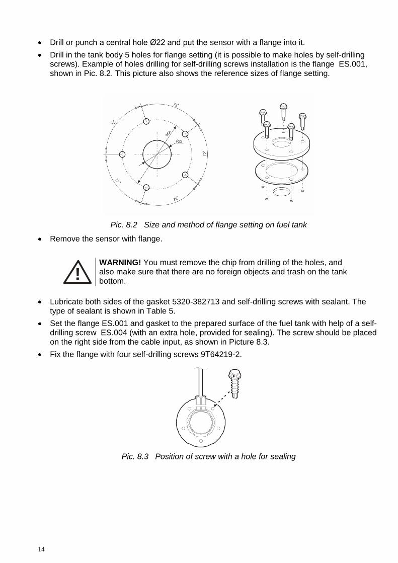
Drill or punch a central hole Ø22 and put the sensor with a flange into it.
Drill in the tank body 5 holes for flange setting (it is possible to make holes by self-drilling screws). Example of holes drilling for self-drilling screws installation is the flange ES.001, shown in Pic. 8.2. This picture also shows the reference sizes of flange setting.
Pic. 8.2 Size and method of flange setting on fuel tank
Remove the sensor with flange.
!
WARNING! You must remove the chip from drilling of the holes, and also make sure that there are no foreign objects and trash on the tank bottom.
Lubricate both sides of the gasket 5320-382713 and self-drilling screws with sealant. The type of sealant is shown in Table 5.
Set the flange ES.001 and gasket to the prepared surface of the fuel tank with help of a self-drilling screw ES.004 (with an extra hole, provided for sealing). The screw should be placed on the right side from the cable input, as shown in Picture 8.3.
Fix the flange with four self-drilling screws 9Т64219-2.
Pic. 8.3 Position of screw with a hole for sealing
EPSILON ES2,ES4
15
8.2 Preparation of sensor for installation
8.2.1 Measuring of probe’s length
It is strongly recommended, whenever possible, to apply probes unified by a manufacturer - this will eliminate extra work during installation or replacement of the sensor. As a rule, unified sensors correspond to the outer height of tanks of the most encountered sizes. For example, the overall height of the tank of trucks of such popular brands as DAF, MAN, Renault, Scania is 620 mm – the sensor with a probe of 620 mm should be applied for them.
The manufacturer of the sensor provides the following range of unified types of sensors.
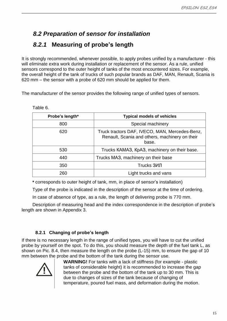
Table 6.
Probe’s length* Typical models of vehicles
800 Special machinery
620 Truck tractors DAF, IVECO, MAN, Mercedes-Benz, Renault, Scania and others, machinery on their
base.
530 Trucks КАМАЗ, КрАЗ, machinery on their base.
440 Trucks МАЗ, machinery on their base
350 Trucks ЗИЛ
260 Light trucks and vans
* corresponds to outer height of tank, mm, in place of sensor’s installation)
Type of the probe is indicated in the description of the sensor at the time of ordering.
In case of absence of type, as a rule, the length of delivering probe is 770 mm.
Description of measuring head and the index correspondence in the description of probe’s length are shown in Appendix 3.
8.2.1 Changing of probe’s length
If there is no necessary length in the range of unified types, you will have to cut the unified probe by yourself on the spot. To do this, you should measure the depth of the fuel tank L, as shown on Pic. 8.4, then measure the length on the probe (L-15) mm, to ensure the gap of 10 mm between the probe and the bottom of the tank during the sensor use.
!
WARNING! For tanks with a lack of stiffness (for example - plastic tanks of considerable height) it is recommended to increase the gap between the probe and the bottom of the tank up to 30 mm. This is due to changes of sizes of the tank because of changing of temperature, poured fuel mass, and deformation during the motion.

16
Pic. 8.4 Determining of measuring probe’s length
Next:
1) Cut the meted part of the probe’s tube. The cut must be made carefully, burrs must be removed. The plane of the cut should be perpendicular to the guide line of the pipe. We recommend using a special tool for cutting pipes. Type of the instrument is listed in Table 5.
2) Install an insulating cap ES.217 at the end of the probe, as shown on Picture 8.5, on the left:
Pic. 8.5 Method of fastening of string on the end of probe
3) Fix the central conductor of the probe. To do this, you should pull up to the stop (the length of free movement of compressing spring 5 mm), fold and put the central conductor to the grooves of stub, as shown on Pictures 8.5 and 8.6.
Pic. 8.6 Way of placement of central conductor on the stub
4) Check the quality of the tension. To do this, you should gently tap with your finger on the probe (probe should be screwed to the measuring head against the stop) – you should feel the vibration of the string taut (central conductor).
Cut the remained part of the conductor in the way that the cut was roughly in the center of a stub.
5) Apply a drop of sealant (type shown in Table 5) on the place of conductor’s cut for providing protection of the end of the conductor from water that may accumulate in the tank.
EPSILON ES2,ES4
17
Install the plug on the cap, shown in Picture 8.5, on the right, and push until it clicks.
Preparation of the sensor for installation is complete. If the sensor is supplied with a probe of unified or special length, the sensor assembly and preparation for installation is performed in factory conditions.
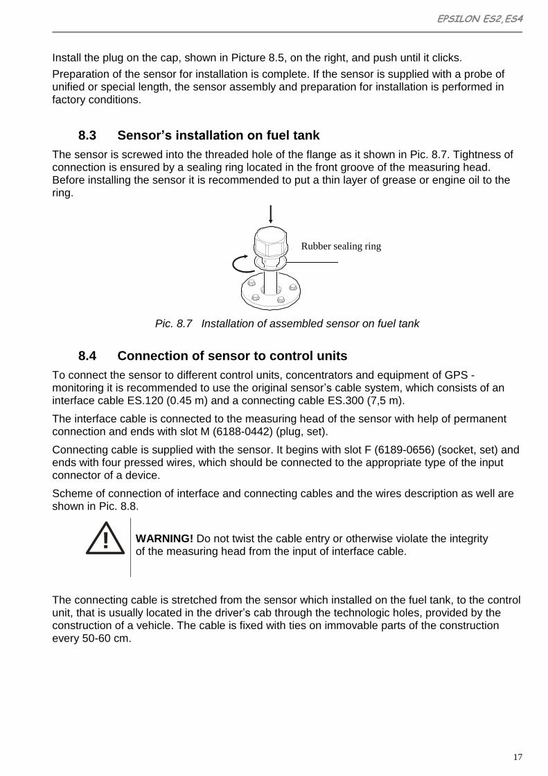
8.3 Sensor’s installation on fuel tank
The sensor is screwed into the threaded hole of the flange as it shown in Pic. 8.7. Tightness of connection is ensured by a sealing ring located in the front groove of the measuring head. Before installing the sensor it is recommended to put a thin layer of grease or engine oil to the ring.
Pic. 8.7 Installation of assembled sensor on fuel tank
8.4 Connection of sensor to control units
To connect the sensor to different control units, concentrators and equipment of GPS - monitoring it is recommended to use the original sensor’s cable system, which consists of an interface cable ES.120 (0.45 m) and a connecting cable ES.300 (7,5 m).
The interface cable is connected to the measuring head of the sensor with help of permanent connection and ends with slot M (6188-0442) (plug, set).
Connecting cable is supplied with the sensor. It begins with slot F (6189-0656) (socket, set) and ends with four pressed wires, which should be connected to the appropriate type of the input connector of a device.
Scheme of connection of interface and connecting cables and the wires description as well are shown in Pic. 8.8.
!
WARNING! Do not twist the cable entry or otherwise violate the integrity of the measuring head from the input of interface cable.
The connecting cable is stretched from the sensor which installed on the fuel tank, to the control unit, that is usually located in the driver’s cab through the technologic holes, provided by the construction of a vehicle. The cable is fixed with ties on immovable parts of the construction every 50-60 cm.
Rubber sealing ring

18
Pic. 8.8 Scheme of connection of interface and connecting cables
Additional instructions of connecting of the sensor to different control units, concentrators and equipment of GPS - monitoring are in the appendixes of this Manual:
- for "Dalcon" concentrator – Appendix 4
- for "АвтоГРАФ –GSM" system – Appendix 5
- for "Teletrack" system – Appendix 6
- for "IntelliTrac" system – Appendix 7
- for "Teltonika" system – Appendix 8
Common earth conductors of the sensor (black wire) and of a control unit must be connected to a single point on the chassis of a vehicle, to which "mass" or "earth" of the other electrical appliances of a vehicle are connected (Pic. 8.9).
ДУТ БУ
-
Выключатель
массы
1
2
...n Э
ле
ктр
опр
иб
ор
ы Т
С
+
Pic. 8.9 CORRECT connection of common wire
Interface cable Connecting cable
Yellow
Green
Red
Black
embedded network general
ES4 ES2 Channel A (RS485) Rx(RS232 output 2 DB9)
Channel B (RS485) Tx(RS232 output 3 DB9)
ES4 ES2 Channel B (RS485) Tx(RS232 output 3 DB9)
Channel A (RS485) Rx(RS232 output 2 DB9)
FLS
Disconnect
Switcher
Electrical appliances of a vehicle
Control
block
EPSILON ES2,ES4
19
!
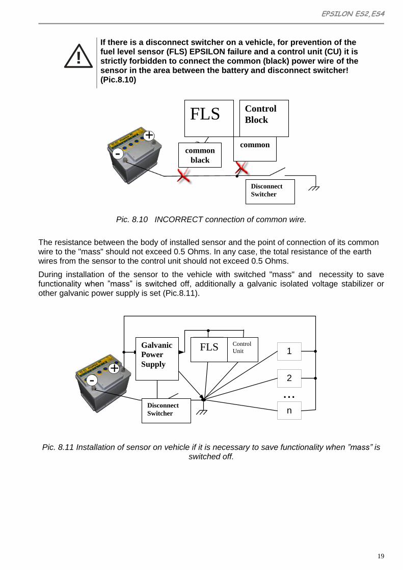
If there is a disconnect switcher on a vehicle, for prevention of the fuel level sensor (FLS) EPSILON failure and a control unit (CU) it is strictly forbidden to connect the common (black) power wire of the sensor in the area between the battery and disconnect switcher! (Pic.8.10)
Pic. 8.10 INCORRECT connection of common wire.
The resistance between the body of installed sensor and the point of connection of its common wire to the "mass" should not exceed 0.5 Ohms. In any case, the total resistance of the earth wires from the sensor to the control unit should not exceed 0.5 Ohms.
During installation of the sensor to the vehicle with switched "mass" and necessity to save functionality when ”mass” is switched off, additionally a galvanic isolated voltage stabilizer or other galvanic power supply is set (Pic.8.11).
ДУТ БУ
-
Выключатель
массы
1
2
...n Э
ле
ктр
опр
иб
ор
ы Т
С
+
Гальвани-
ческая
развязка
питания
+
Pic. 8.11 Installation of sensor on vehicle if it is necessary to save functionality when ”mass” is switched off.
FLS Control
Block
Disconnect
Switcher
Disconnect
Switcher
common common
black
FLS Control
Unit Galvanic
Power
Supply

20
8.5 Sealing of sensor
To protect the sensor from unauthorized interference you should install two seals. The first seal prevents the measuring head from twisting and the second one is set on a detachable connection of interface and connecting cables.
For sealing of the measuring head (look pic. 8.12):
make a wire loop;
tightly wrap the hermetic input;
make a twist of wire and thread the wire through the hole of the screw ES.004;
place the ends of the wire in the seal (using СИЛТЕК seal ends of the wire should go through the holes of the seal on the side opposite to marking);
Select the wire slack and snap the seal.
Pic. 8.12 Method of sealing of the installed fuel level sensor
For additional mechanical fixation of the seal we recommend to drag it to hermetic output and press with a plastic electro technical clamp tie.
9. Calibration
To ensure the most accurate control of fuel level, tank calibration is performed - initially empty (full) tank is filled (merged) by equal portions of fuel and with the help of special software "eS Install" the sensors statements are measured and fixed after adding (pluming) of each portion.
Portion sizes should be chosen depending on configuration of a tank: if horizontal cross-sectional area of the tank in height is sharply changing the portion should be the less. (For example, the recommended portion for a 500 l tank of КамАЗ should be 10 l). You must also take into account the time of level balancing level in tanks of complex configuration (for example, in 2-tank systems) due the fuel flow.
Requirements to a measuring cup or a flow meter that provides a measurement of portions are shown in Table 4.

EPSILON ES2,ES4
21
!
WARNING! Calibration of the tank must be made using the same type of fuel, with which the sensor will be operating (for example, you can not use petrol for calibration, if you intend to operate with diesel fuel).
To achieve the most accurate operating features of the sensor it is desirable to make “training”. It is sufficient to perform the calibration procedure not immediately after installation of a sensor, but after some time of car’s usage, when 50 – 70% of tank’s fuel capacity is used. During this time, mechanical clearances will normalize, guaranteed by the rubber gasket flange and a polymer sealant, and on the entire surface of the probe a stable dielectric fuel film is formed.
If the "training" of the sensor can not be performed, before the calibration of the tank by filling it with use of a new sensor (probe), the probe must be immersed into the fuel than removed and you should allow the fuel to drain for 20-30 minutes. If the calibration is performed by the method of draining, this procedure is not performed.
At the time of calibration you must disconnect the sensor from the on-board controller and connect it to the port of used PC (requirement to PC and port converter are shown in Table 5). At the end of calibration a connection to the on-board controller should be restored.
The result of calibration in the form of tank calibration table and user’s data about work executed is storing on the PC in a format which guarantees the data exchange into Dispatch Software. Detailed procedure of calibration using software application eS Install is described in Appendix 1.
10. Maintenance
The sensor is unattended product, but if the rules of vehicle maintenance provide the procedure of fuel tank prevention; it is advisable to execute simultaneously preventive service of the sensor.
For sensor’s preventive service you have to:
Perform a complete removal of the sensor (see Pic.10.2);
Wash the probe from inside by the fuel (in which sensor is operating) and blow with compressed air.
Check own parameters of the measuring head (by using "eS Install").
Perform installation and sealing of the sensor according to the requirements of section 8.
Measuring head of the sensor is not repairable product and during the warranty period preserves the stability of its metrological parameters.
In the case of failure of the measuring head you must perform the following:
If you want to use vehicle before a new measuring head is installed, it is necessary to make a partial removal of the sensor (see Pic. 10.1).

22
For new measuring head you have to install (by using eS Install) an appropriate unified type (indicated in the calibration protocol).
If you use User’s type, it is necessary to perform automatic zero installation again, and then by additional manual zero installation (see Appendix 1) to set for an empty probe (firstly you should remove the probe from the fuel and wait until the fuel drain) the same level code as specified in the calibration protocol of this tank.
Install and connect a new measuring head, make the sensor sealing in accordance with the requirements of section 8.
Partial removal of the sensor is made as follows:
Disconnect the interface and connecting cables.
Remove only the measuring head of the sensor.
If necessary, partially tighten the sleeve of the sensor’s probe into the flange, as shown in Pic. 10.1.
Close the sleeve of the sensor’s probe by a cap.
Pic. 10.1 Partial removal of fuel level sensor
Complete removal of the sensor is made as follows:
Disconnect the interface and connecting cables.
Remove the measuring head and then the sensor’s probe from the flange.
Close the hole of the flange by the plug M 25 x 1.5 (see Table 3), as shown in Pic. 10.2.
Pic. 10.2 Complete removal of fuel level sensor

EPSILON ES2,ES4
23
11. Transportation and Storage
Transportation of the sensor in transport package of the manufacturer is allowed by all means of closed land and sea transport (railway cars, containers, closed vehicles, holds, etc.). It is possible to transport in sealed heated compartments of airplanes. Transportation and storage must be done in terms that correspond to conditions of storage 3 according to ГОСТ 15150-69.
During transportation and storage requirements of manipulation signs, printed on transport package must be complied.
12. Warranty
Warranty period of operation of the sensor is 18 months from the date of entry into operation of the sensor, but not more than 24 months from the date of production. Date of entry into operation should be fixed in accordance with the requirements assigned in passport of the sensor. If there is no such data in the passport the warranty period begins on the date of shipment of the sensor to the consumer. Manufacturer's warranties are valid if the consumer follows the requirements of this service manual. In case of violation, or if there is any mechanical or electrical damage caused by influence of factors, not provided by this service manual, warranty is considered to be expired.

24
APPENDIXES
Appendix 1
Software Application "eS Install" (v. 1.0.1.18)
The software application "eS Install" (hereinafter - the Program) is designed to provide calibration process of a fuel tank and to make a calibration table that describes the dependence of the output code of the sensor on the fuel level.
The program is included to users software (SW), supplied on compact-disk (name ES.000 CD1). To install on a personal computer (PC) it is enough to copy the program into the desired folder. In addition, ports RS-485 (for a model eS4) or RS-232 (model eS2) must be installed on PC For a laptop it is recommended to use converters MOXA: USB/RS-485 UPort 1130 or USB/RS-232 UPort 1110.
To get started with the program you need to connect the sensor to correct port (complying the polarity of interface and the supply conductors) and provide sourcing of the sensor from an onboard network of the vehicle or from an external source (power settings - in accordance with Table 1 of section 3 of this manual).
After launch, in the window "eS Install" you have to select the desired COM port and set the exchange speed. By default, the sensor with factory settings has the exchange speed of 19200. Windows RTS and DTR you have to leave unchecked (engineering view).
In the same window there are available menu options such as "Файл (File)", "Опции (Options)", "Вид (Type)" and «Help» (their purpose is described below).
At the bottom of the window the status of the port is displayed:
If you see message "Port is closed" you have to press active bottom and program is ready for use.
“COM port N 5 is open“ this message means that COM port is open and works correctly.
“Error in port 257 opening” - message indicates that the COM port is opening with an error. In this case, you should check and set up the functionality of the port on the level of drivers or check the condition of the COM port itself.
For beginning of the process (calibration), press the button .
The presence of the symbol "Search", marked by the frame in the picture above, shows that a device (sensor) is not connected to the specified COM port.
In case of normal program start the tab “Information” will be shown.
EPSILON ES2,ES4
25
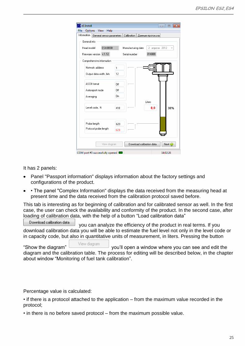
It has 2 panels:
Panel "Passport information" displays information about the factory settings and configurations of the product.
• The panel "Complex Information" displays the data received from the measuring head at present time and the data received from the calibration protocol saved before.
This tab is interesting as for beginning of calibration and for calibrated sensor as well. In the first case, the user can check the availability and conformity of the product. In the second case, after loading of calibration data, with the help of a button “Load calibration data”
you can analyze the efficiency of the product in real terms. If you download calibration data you will be able to estimate the fuel level not only in the level code or in capacity code, but also in quantitative units of measurement, in liters. Pressing the button
“Show the diagram” you’ll open a window where you can see and edit the diagram and the calibration table. The process for editing will be described below, in the chapter about window “Monitoring of fuel tank calibration”.
Percentage value is calculated:
• if there is a protocol attached to the application – from the maximum value recorded in the protocol;
• in there is no before saved protocol – from the maximum possible value.

26
To continue, press the button “NEXT”
On the tab "Sensor’s general options” you can see parameters of data exchange with an external controller.
Meaning of parameters:
"Turn on a text format" - activates the data output in text format (takes effect when you click
"APPLY" and restart the sensor by power reset). By default is not activated.
"Turn on periodic issuance" - activates the periodic issuance of the data. By default is not activated.
"Repeat Interval" - defines the repeat interval during periodic issuance in seconds.
"Turn on averaging "- activates averaging of the data.
«Exchange speed on UART» - allows you to install one of the seven proposed exchange speeds.
«Device network address" - may have value from 0 to 255. Defines the network address of
the sensor. By default is 1. If the system uses several sensors, they must have unique
addresses, each of them must to be made individually for each sensor.
"Capacity" - the capacity of data that determine the fuel level.
EPSILON ES2,ES4
27
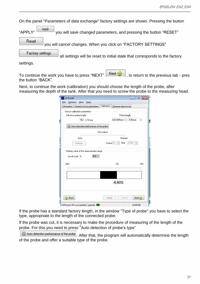
On the panel "Parameters of data exchange" factory settings are shown. Pressing the button
“APPLY” you will save changed parameters, and pressing the button “RESET”
you will cancel changes. When you click on “FACTORY SETTINGS”
all settings will be reset to initial state that corresponds to the factory
settings.
To continue the work you have to press “NEXT” , to return to the previous tab - pres the button “BACK”.
Next, to continue the work (calibration) you should choose the length of the probe, after measuring the depth of the tank. After that you need to screw the probe to the measuring head.
If the probe has a standard factory length, in the window "Type of probe" you have to select the type, appropriate to the length of the connected probe.
If the probe was cut, it is necessary to make the procedure of measuring of the length of the
probe. For this you need to press “Auto detection of probe’s type”
. After that, the program will automatically determine the length of the probe and offer a suitable type of the probe.

28
If the probe is shorter than 185 mm or longer than 725 mm, you will be offered to install the type "User’s L» or «User’s H», respectively. In this case, you will have to make zero installation of a measuring head.
Attention!
Effective range is 846 mm, the probe type
“User’s H” will be set.
OK
Zero installation is recommended to make in automatic mode, for this you should press button “MAKE”. If necessary, you can make more correct manual setting, increasing or decreasing the value in the box "Exact". In this case the deviation of the relative position of range start will be indicated in the lower field in the form of a line with an indication of percentage value (from the value of the full range). Allowable deviation is within the whole window; going beyond its limits will be displayed by flashing, colored in red, figures of percentage value.
Sensors of modifications ES2X, ES2XL, ES2XXL, ES4X, ES4XL, ES4XXL are produced according to given ranges of probes’ length and do not need calibration. The program automatically determines the model of the sensor. If the connected sensor’s model is one of listed above, there is not the tab "Calibration". To continue the work and transfer to the tab "Calibration" it is necessary to select the protocol
and filling the data of calibration protocol. By pressing to the button “NEXT” the program will offer you to select the protocol. If everything is done right, on your screen the window of protocol select will appear.
Next, you have to create a file calibration protocol or select a necessary one of created before (if the calibration, for whatever reason has not been completed and it is necessary to continue it). In the window "Protocol select", the newly created protocols are available. To view those
saved before use the button and navigate to the choice of protocol by operating system tools.

EPSILON ES2,ES4
29
The data of calibration will be saved in this protocol file; in the case of abnormal power
disconnection of PC data will not be lost.
After selecting the protocol the tab «Data Protocol" will open.
Data made on this tab are complementary and they are used by technical support service. They
do not affect to the calibration, but are saved in the "cap" of calibration table.
To start the calibration it is necessary to fill all the fields on the tab "Data Protocol" and press
button “NEXT” .
“Monitoring of fuel tank calibration”
30
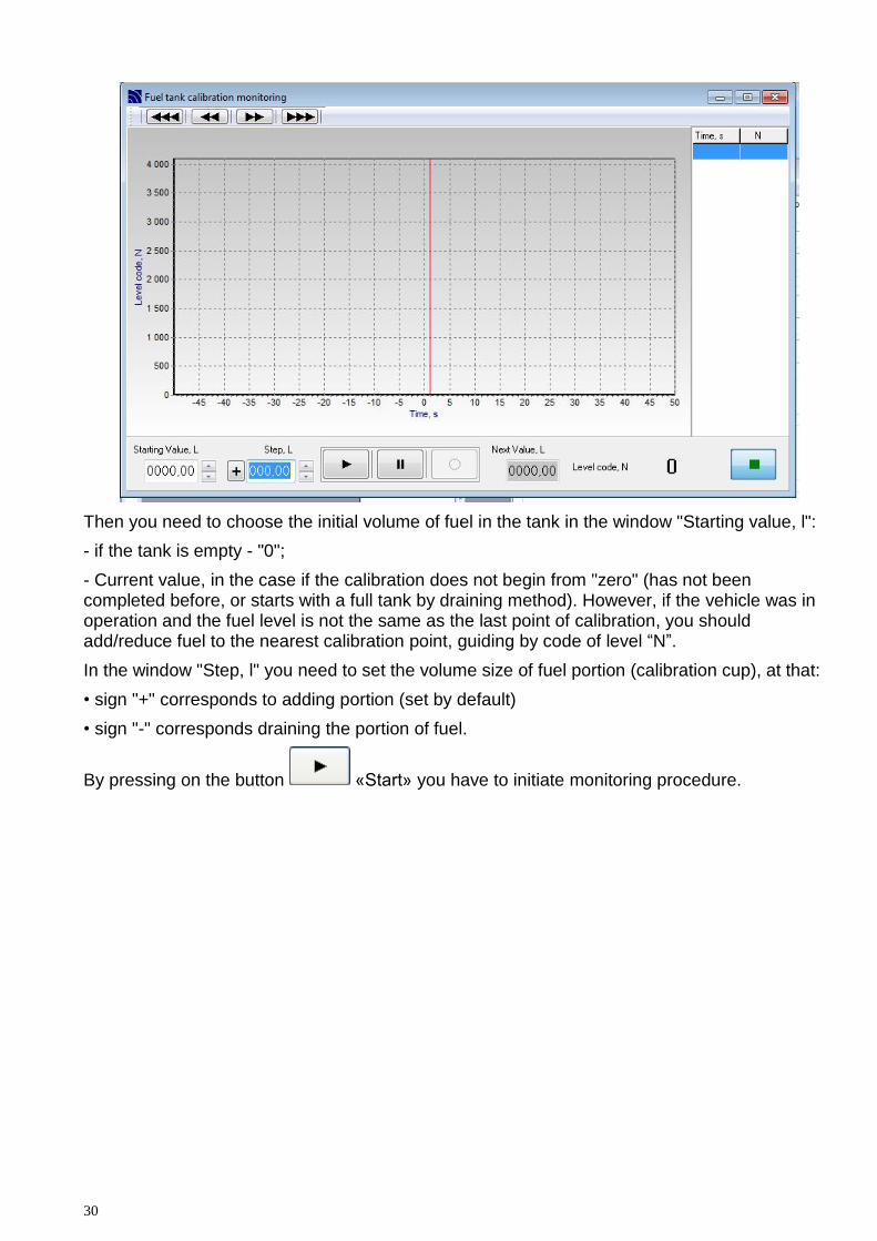
Then you need to choose the initial volume of fuel in the tank in the window "Starting value, l":
- if the tank is empty - "0";
- Current value, in the case if the calibration does not begin from "zero" (has not been completed before, or starts with a full tank by draining method). However, if the vehicle was in operation and the fuel level is not the same as the last point of calibration, you should add/reduce fuel to the nearest calibration point, guiding by code of level “N”.
In the window "Step, l" you need to set the volume size of fuel portion (calibration cup), at that:
• sign "+" corresponds to adding portion (set by default)
• sign "-" corresponds draining the portion of fuel.
By pressing on the button «Start» you have to initiate monitoring procedure.

EPSILON ES2,ES4
31
To record the point of calibration, press the button «Rec», to pause the scrolling (with
long pauses) – press «Pause». In the box "Next value, l" you will see the prompt - the
expected amount of the fuel in the tank. If this value is in the process of calibration will exceed
the tank amount, indicated in the protocol, the window will be colored in orange for warning.
Code level, N is the result of measuring the fuel level by sensor eS4. It is displayed in decimal
format. If you will have 12-bit representation a typical value (in empty tank) is: for unified types
and for "User’s L" - N = 625, for "User’s H" - N = 100. During the rising of fuel level in the tank N
increases, the maximum value for type 710 is N = 4095.
The information about each saved calibration point is displayed on the graph. For taking extend information you have to click the left mouse button on the relevant position in the table on the right (or on the graph), this will give you transition to a selected point on the graph (and in the table). For editing of selected point you have to press the right mouse button and select one of listed menu items.
«Change fuel level of selected point» - if you choose this item you will see a dialog box "Fuel Level" in which you have to enter a new value in liters for the selected point. After pressing the button you will be offered to change the values all next points to quantity of values difference.
Pressing the button , changes all next values. To change only selected point you have
to press , to complete without changes press .

32
«Delete selected point» - when you select this item a dialog box "Information" will be shown.
Here all the properties of the deleting point will be listed. If you will press the selected
point will be deleted. – log out without changes.
"Properties" - when this option is selected you will see a dialog box in which all the properties of the point will be listed.
Left overhead there are buttons of the graph scroll to the left/right.
Scaling is performed by selection of appropriate window (to fix an angle - press the left mouse
button, then draw:
to increase - from left to right, from top to bottom;
to decrease - from right to left, from bottom to top).
EPSILON ES2,ES4
33
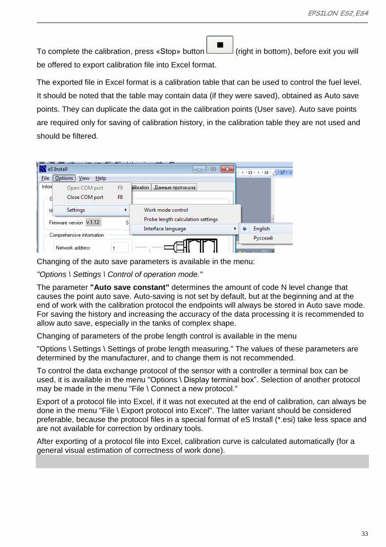
To complete the calibration, press «Stop» button (right in bottom), before exit you will
be offered to export calibration file into Excel format.
The exported file in Excel format is a calibration table that can be used to control the fuel level.
It should be noted that the table may contain data (if they were saved), obtained as Auto save
points. They can duplicate the data got in the calibration points (User save). Auto save points
are required only for saving of calibration history, in the calibration table they are not used and
should be filtered.
Changing of the auto save parameters is available in the menu:
"Options \ Settings \ Control of operation mode."
The parameter "Auto save constant" determines the amount of code N level change that causes the point auto save. Auto-saving is not set by default, but at the beginning and at the end of work with the calibration protocol the endpoints will always be stored in Auto save mode. For saving the history and increasing the accuracy of the data processing it is recommended to allow auto save, especially in the tanks of complex shape.
Changing of parameters of the probe length control is available in the menu
"Options \ Settings \ Settings of probe length measuring." The values of these parameters are determined by the manufacturer, and to change them is not recommended.
To control the data exchange protocol of the sensor with a controller a terminal box can be used, it is available in the menu "Options \ Display terminal box”. Selection of another protocol may be made in the menu "File \ Connect a new protocol."
Export of a protocol file into Excel, if it was not executed at the end of calibration, can always be done in the menu "File \ Export protocol into Excel". The latter variant should be considered preferable, because the protocol files in a special format of eS Install (*.esi) take less space and are not available for correction by ordinary tools.
After exporting of a protocol file into Excel, calibration curve is calculated automatically (for a general visual estimation of correctness of work done).
34
Appendix 2
UNIFIED PROTOCOL Epsilon Data Exchange (EDE)
A2.1 General Provisions
This document describes a protocol of data exchange of fuel level sensors «Epsilon» (hereinafter referred to as FLS) with external devices. Two types of exchange protocols are supported: in a binary form (HEX) or in a symbolic form (ASCII-sequences transfer). For work it is recommended to use a binary exchange protocol. After powering of FLS and before issuing the first command of request you should wait not less than 250 ms. The command, sent in 250 ms after switching on, will not be accepted by FLS. It is also possible do not get the answer to the request if the FLS is busy (data processing is running). In this case, the command should be repeated in 100 ... 200 ms. The reaction time on the received reading command (except a reading command of supply voltage) does not exceed 5.5 ms. Reaction time to reading command of supply voltage is approximately 250 ms. The reaction time to the command of parameters saving is no more than 200 ms. To avoid "hanging" during an unexpected serial interface disconnection timeout on symbol receiving is used - about 100 ms. If during this time the expected symbol is not received, FLS does not answer and goes into standby mode to next command.
A2.2 Serial port settings.
Exchange speed corresponds to the parameter set in the sensor (19 200 bit/s by default). Data capacity - 8 bits. Parity - not checked. Stop bit - 1. Flow control – switched off.
A2.3. Description of commands for binary exchange protocol.
A2.3.1 Message format for binary exchange protocol.
All commands of a binary exchange protocol have the same standardized form: Commands and messages format for binary exchange protocol.
Field serial number Name of field Size of field, Bytes Description
1 Prefix 1
Field is a marker of message beginning. Incoming messages must have prefix 31h, and outgoing message must be issued by a program with prefix 3Eh.

EPSILON ES2,ES4
35
2 Network address 1
Field contains: - network address of acceptor for prefix 31h; - network address of message sender for prefix 3Eh;
3 Command code 1
Field contains: - for prefix 31h – code of command code, that FLS has to comply; - for the prefix 3Eh – code of command, on which FLS gives the answer.
4 Command parameters
Depends on the command code
The data composition and the format of the field depends from the command code.
5 CRC8 1
This field is used to control data integrity. Calculated from all the previous bytes in accordance with Application Note 27 from Dallas.
Multi-byte command parameters are transferred in order from a junior byte to a senior one(«low endian»).
A2.3.2 Description of computer code.
A2.3.2.1 Common commands for FLS of all modifications.
A2.3.2.1.1. Single data reading (command 06h).
The command is designed for reading of current data: user’s value of fuel level (10 or 12 bits), technological value of fuel level (16 bit), temperature (8 bits). Command format:
Drift, byte Size of field, byte
Value Description
0 1 31h Prefix
+1 1 00h…FFh Network address of
acceptor
+2 1 06h Command code
+3 1 00h…FFh CRC8
Answer format:
Drift, byte Size of field, byte
Value Description
0 1 3Eh Prefix
+1 1 00h…FFh Network address of
sender
+2 1 06h Command code
+3 1 -128…127 Temperature in degrees
of centigrade

36
+4 2 0000h…03FFh
or 0000h…0FFFh User’s value of fuel level
+6 2 0000h…FFFFh Technological value of
fuel level
+8 1 00h…FFh CRC8
A2.3.2.1.2 Unsolicited (periodic) data output (command 07h).
In message current data is transferred: User’s value of fuel level (10 or 12 bits), technological value of fuel level (16 bit), temperature (8 bits). Message format:
Drift, byte Size of field, byte
Value Description
0 1 3Eh Prefix
+1 1 00h…FFh Network address of
sender
+2 1 07h Command code
+3 1 -128…127 Temperature in degrees
of centigrade
+4 2 0000h…03FFh
or 0000h…0FFFh User’s value of fuel level
+6 2 0000h…FFFFh Technological value of
fuel level
+8 1 00h…FFh CRC8
Turning on of the periodic data output is performing by command 55h. In case of receiving of any valid command periodic data output is disabled, for it’s turning on you have to restart FLS (switch off and switch on of power supply).
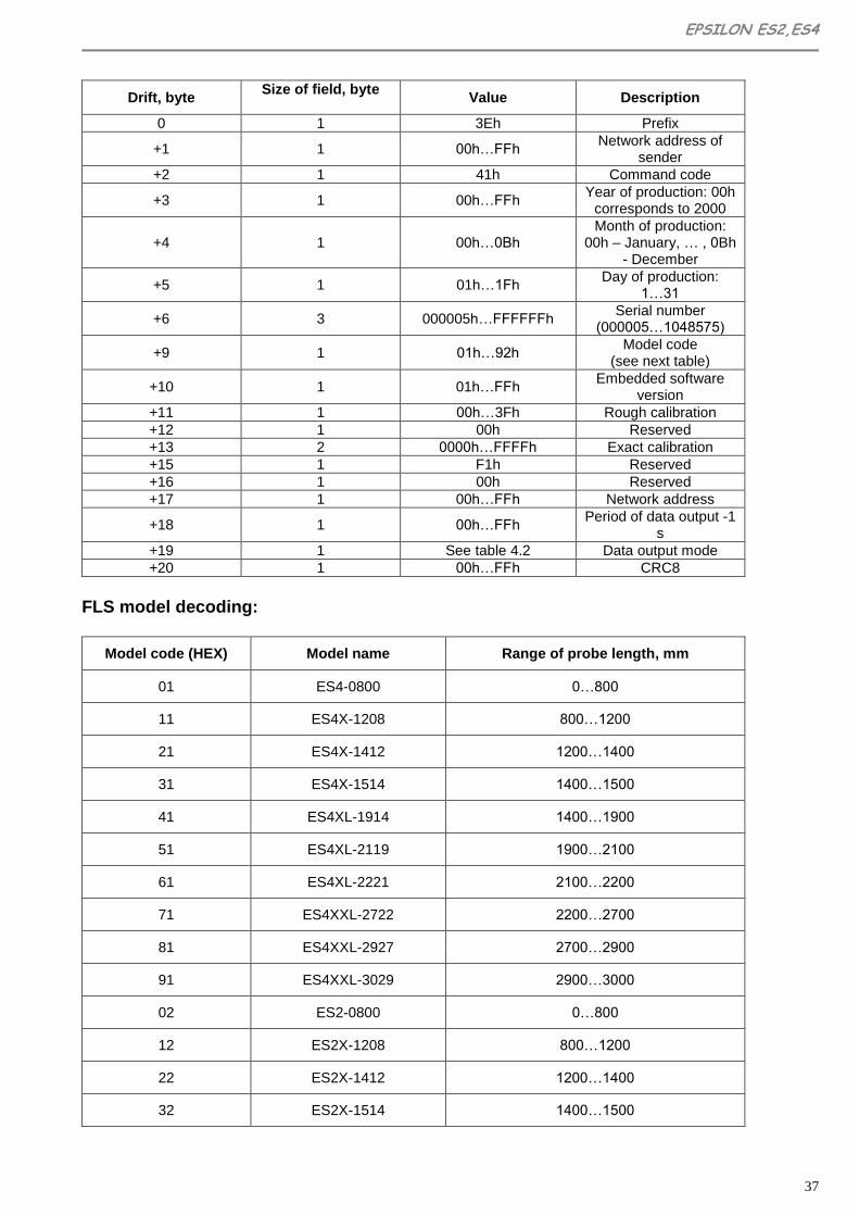
P2.3.2.1.3 Reading of technological parameters (command 41h).
The command is designed for reading of technological parameters of FLS: date of production, serial number, model code, embedded software version, current calibration data, network address, period of data output, data output mode. Command format:
Drift, byte Size of field, byte
Value Description
0 1 31h Prefix
+1 1 00h…FFh Network address of
acceptor
+2 1 41h Command code
+3 1 00h…FFh CRC8
Answer format:
EPSILON ES2,ES4
37
Drift, byte Size of field, byte
Value Description
0 1 3Eh Prefix
+1 1 00h…FFh Network address of
sender
+2 1 41h Command code
+3 1 00h…FFh Year of production: 00h
corresponds to 2000
+4 1 00h…0Bh Month of production:
00h – January, … , 0Bh - December
+5 1 01h…1Fh Day of production:
1…31
+6 3 000005h…FFFFFFh Serial number
(000005…1048575)
+9 1 01h…92h Model code
(see next table)
+10 1 01h…FFh Embedded software
version
+11 1 00h…3Fh Rough calibration
+12 1 00h Reserved
+13 2 0000h…FFFFh Exact calibration
+15 1 F1h Reserved
+16 1 00h Reserved
+17 1 00h…FFh Network address
+18 1 00h…FFh Period of data output -1
s
+19 1 See table 4.2 Data output mode
+20 1 00h…FFh CRC8
FLS model decoding:
Model code (HEX) Model name Range of probe length, mm
01 ES4-0800 0…800
11 ES4X-1208 800…1200
21 ES4X-1412 1200…1400
31 ES4X-1514 1400…1500
41 ES4XL-1914 1400…1900
51 ES4XL-2119 1900…2100
61 ES4XL-2221 2100…2200
71 ES4XXL-2722 2200…2700
81 ES4XXL-2927 2700…2900
91 ES4XXL-3029 2900…3000
02 ES2-0800 0…800
12 ES2X-1208 800…1200
22 ES2X-1412 1200…1400
32 ES2X-1514 1400…1500

38
42 ES2XL-1914 1400…1900
52 ES2XL-2119 1900…2100
62 ES2XL-2221 2100…2200
72 ES2XXL-2722 2200…2700
82 ES2XXL-2927 2700…2900
92 ES2XXL-3029 2900…3000
A2.3.2.1.4 Reading of serial number and date of production (command 42h). The command is designed for reading of following FLS parameters: date of production, serial number, model code, embedded software version. Command format:
Drift, byte Size of field, byte
Value Description
0 1 31h Prefix
+1 1 00h…FFh Network address of
acceptor
+2 1 42h Command code
+3 1 00h…FFh CRC8
Answer format:
Drift, byte Size of field, byte
Value Description
0 1 3Eh Prefix
+1 1 00h…FFh Network address of
sender
+2 1 42h Command code
+3 1 00h…FFh Year of production: 00h
corresponds to 2000
+4 1 00h…0Bh Month of production:
00h – January, … , 0Bh - December
+5 1 01h…1Fh Day of production:
1…31
+6 3 000005h…FFFFFFh Serial number
(000005…1048575)
+9 1 01h…92h Model code
(see table 4.1)
+10 1 01h…FFh Embedded software
version
+11 1 00h…FFh CRC8
A2.3.2.1.5 Reading of supply voltage (command 50h).
Command is designed for getting current value of voltage of built-in stabilizer. Command format:
Drift, byte Size of field, byte
Value Description
0 1 31h Prefix

EPSILON ES2,ES4
39
+1 1 00h…FFh Network address of
acceptor
+2 1 50h Command code
+3 1 00h…FFh CRC8
Answer format:
Drift, byte Size of field, byte
Value Description
0 1 3Eh Prefix
+1 1 00h…FFh Network address of
sender
+2 1 50h Command code
+3 2 Vcc=0000h…7FFFh Formula evaluation of
supply voltage: U=Vcc/4667,8.
+5 1 00h…FFh CRC8
A2.3.2.1.6 Installing of the period of data output (command 54h).
The command is designed for setting of period of data output. Command format:
Drift, byte Size of field, byte
Value Description
0 1 31h Prefix
+1 1 00h…FFh Network address of
acceptor
+2 1 54h Command code
+3 1 00h…FFh Value of the period of data
output -1 s
+4 1 00h…FFh CRC8
Answer format:
Drift, byte Size of field, byte
Value Description
0 1 3Eh Prefix
+1 1 00h…FFh Network address of
sender
+2 1 54h Command code
+3 1 00h or 01h
Return code: 00h - command is complied
successfully, 01h - Error
+4 1 00h…FFh CRC8
A2.3.2.1.7 Installing of data output mode (command 55h).
The command is designed for setting of following parameters: data output capacity (10 or 12 bits), periodic data output (On/Off), resolution
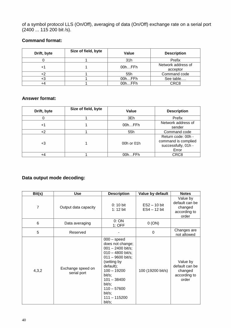
40
of a symbol protocol LLS (On/Off), averaging of data (On/Off) exchange rate on a serial port (2400 ... 115 200 bit /s). Command format:
Drift, byte Size of field, byte
Value Description
0 1 31h Prefix
+1 1 00h…FFh Network address of
acceptor
+2 1 55h Command code
+3 1 00h…FFh See table….
+4 1 00h…FFh CRC8
Answer format:
Drift, byte Size of field, byte
Value Description
0 1 3Eh Prefix
+1 1 00h…FFh Network address of
sender
+2 1 55h Command code
+3 1 00h or 01h
Return code: 00h - command is complied
successfully, 01h - Error
+4 1 00h…FFh CRC8
Data output mode decoding:
Bit(s) Use Description Value by default Notes
7 Output data capacity 0: 10 bit 1: 12 bit
ES2 – 10 bit ES4 – 12 bit
Value by default can be
changed according to
order
6 Data averaging 0: ON 1: OFF
0 (ON)
5 Reserved - 0 Changes are not allowed
4,3,2 Exchange speed on
serial port
000 – speed does not change; 001 – 2400 bit/s; 010 – 4800 bit/s; 011 – 9600 bit/s; (setting by default); 100 – 19200 bit/s; 101 – 38400 bit/s; 110 – 57600 bit/s; 111 – 115200 bit/s;
100 (19200 bit/s)
Value by default can be
changed according to
order
EPSILON ES2,ES4
41
1 Symbol protocol LLS 0: denied 1: allowed
0 (denied)
Value by default can be
changed according to
order
0 Periodic data output after
restart 0: OFF 1: ON
0 (OFF)
Value by default can be
changed according to
order
NOTES. Setting of exchange speed and resolution of data output in symbol format is used in FLS ES2, ES4 with software versions 1.8 and higher, as well as in ES2X, ES2XL, ES2XXL, ES4X, ES4XL, ES4XXL with embedded software versions: 4.6, 4.7, 4.10 and higher. Periodic data output mode is used in ES2, ES4 with software versions: 1.3, 1.4, 1.7 and higher, as well as in ES2X, ES2XL, ES2XXL, ES4X, ES4XL, ES4XXL with embedded software versions: 4.6, 4.7, 4.10 and higher. For ES2, ES4 with software versions 1.3, 1.4, ; bits 1 ... 6 in the command parameter must be equal to 0.
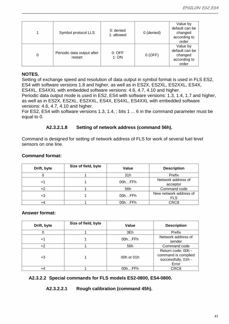
A2.3.2.1.8 Setting of network address (command 56h).
Command is designed for setting of network address of FLS for work of several fuel level sensors on one line.
Command format:
Drift, byte Size of field, byte
Value Description
0 1 31h Prefix
+1 1 00h…FFh Network address of
acceptor
+2 1 56h Command code
+3 1 00h…FFh New network address of
FLS
+4 1 00h…FFh CRC8
Answer format:
Drift, byte Size of field, byte
Value Description
0 1 3Eh Prefix
+1 1 00h…FFh Network address of
sender
+2 1 56h Command code
+3 1 00h or 01h
Return code: 00h - command is complied
successfully, 01h - Error
+4 1 00h…FFh CRC8
A2.3.2.2 Special commands for FLS models ES2-0800, ES4-0800.
A2.3.2.2.1 Rough calibration (command 45h).
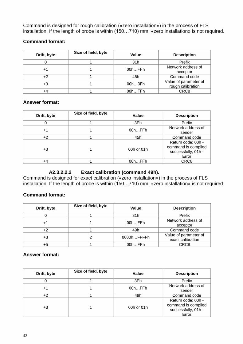
42
Command is designed for rough calibration («zero installation») in the process of FLS installation. If the length of probe is within (150…710) mm, «zero installation» is not required.
Command format:
Drift, byte Size of field, byte
Value Description
0 1 31h Prefix
+1 1 00h…FFh Network address of
acceptor
+2 1 45h Command code
+3 1 00h…3Fh Value of parameter of
rough calibration
+4 1 00h…FFh CRC8
Answer format:
Drift, byte Size of field, byte
Value Description
0 1 3Eh Prefix
+1 1 00h…FFh Network address of
sender
+2 1 45h Command code
+3 1 00h or 01h
Return code: 00h - command is complied
successfully, 01h - Error
+4 1 00h…FFh CRC8
A2.3.2.2.2 Exact calibration (command 49h).
Command is designed for exact calibration («zero installation») in the process of FLS installation. If the length of probe is within (150…710) mm, «zero installation» is not required Command format:
Drift, byte Size of field, byte
Value Description
0 1 31h Prefix
+1 1 00h…FFh Network address of
acceptor
+2 1 49h Command code
+3 2 0000h…FFFFh Value of parameter of
exact calibration
+5 1 00h…FFh CRC8
Answer format:
Drift, byte Size of field, byte
Value Description
0 1 3Eh Prefix
+1 1 00h…FFh Network address of
sender
+2 1 49h Command code
+3 1 00h or 01h
Return code: 00h - command is complied
successfully, 01h - Error

EPSILON ES2,ES4
43
+4 1 00h…FFh CRC8
A2.3.2.2.3 Reading of probe’s length parameter (command 4Dh).
Command is designed for reading of current value of probe’s length parameter. Command format:
Drift, byte Size of field, byte
Value Description
0 1 31h Prefix
+1 1 00h…FFh Network address of
acceptor
+2 1 4Dh Command code
+3 1 00h…FFh CRC8
Answer format:
Drift, byte Size of field, byte
Value Description
0 1 3Eh Prefix
+1 1 00h…FFh Network address of
sender
+2 1 4Dh Command code
+3 1 00h…07h Parameter of probe’s
length
+4 1 00h…FFh CRC8
Probe’s length parameter decoding
Value of probe’s length parameter
Manufacturer's type mark
Allowable length of probe, mm
Notes
0 User’s L 0…260 Calibration is made during installation
1 User’s H 710…800 Calibration is made during installation
2 260 150…340 Manufacturer’s
calibration
3 350 270…430 Manufacturer’s
calibration
4 440 360…520 Manufacturer’s
calibration
5 530 450…610 Manufacturer’s
calibration
6 620 540…650 Manufacturer’s
calibration
7 710 630…710 Manufacturer’s
calibration
A2.3.2.2.4 Select of probe’s length parameter (command 4Eh).
The command is designed for selecting of probe’s length in a line from 0 to 7.

44
The parameter values from 2 to 7 correspond to the factory calibration for the standard series of probe length. In these cases the calibration of FLS during the installation is not required, you just have to select the parameter of probe’s length according to Table 4.3. The value of "0" is applied if the probe’s length is less than 150 mm, the value "1" is applied if the length of the probe is in the range of (710 ... 800) mm. In these cases, the calibration of FLS is made during its installation. Command format:
Drift, byte Size of field, byte
Value Description
0 1 31h Prefix
+1 1 00h…FFh Network address of
acceptor
+2 1 4Eh Command code
+3 1 00h…07h Parameter of probe’s length (look table 4.3)
+4 1 00h…FFh CRC8
Answer format:
Drift, byte Size of field, byte
Value Description
0 1 3Eh Prefix
+1 1 00h…FFh Network address of
sender
+2 1 4Eh Command code
+3 1 00h or 01h
Return code: 00h - command is complied
successfully, 01h - Error
+4 1 00h…FFh CRC8
A2.3.2.2.5 Storing of calibration data for set-up probe’s length parameter (command 4Fh).
The command is designed for storing in non-volatile memory of parameters, set by commands 45h and 49h during calibration («zero installation») for a set-up probe’s length parameter. Command format:
Drift, byte Size of field, byte
Value Description
0 1 31h Prefix
+1 1 00h…FFh Network address of
acceptor
+2 1 4Fh Command code
+3 1 00h или 01h Parameter of probe’s
length
+4 1 00h…FFh CRC8
Answer format:
Drift, byte Size of field, byte
Value Description
0 1 3Eh Prefix

EPSILON ES2,ES4
45
+1 1 00h…FFh Network address of the
sender
+2 1 4Fh Command code
+3 1 00h или 01h
Return code: 00h - command is complied
successfully, 01h - Error
+4 1 00h…FFh CRC8
A2.3.2 Support for symbol protocol LLS.
A2.3.2.1 Format of data output (example):
F=FFFF t=1A N=03FF.0<CR><LF> , where: F – 16-bit code of measured capacity. t – temperature, °C N – user code of the measured capacity (always 10 bits despite the parameter set by command 55h).
A2.3.2.2 Supported commands of symbol protocol LLS.
DO – request for one-time data output. At the moment of receiving this command FLS shows data 1 time in the format described in P 5.1. DP – switching on of periodic data output. This command is sent only once, after which FLS shows data in the format described in Section 5.1., with interval set by command 54h. This mode does not depend on the resolution of periodic data output set by command 55h and is stored until receiving any valid command of EDE protocol or to the turning off and restart of FLS. For work with a symbol protocol, bit 1 must be installed in the parameter of command 55h. Otherwise, commands DO and DP are ignored, and the periodic data output, if installed, is made in a binary format in accordance with p.4.1.2.

46
Appendix 3
Measuring head marking.
Example of measuring head marking:
Without index - normal, value of division 1Δ (~ 0.20 mm/un. code); Х - long, value of division 2Δ, the same; ХL - long, value of division 3Δ, the same; ХXL - long, for work with a thickened probe; value of division 3,75Δ
Correspondence of index in head marking to the length of the probe:
Used head Used probe
Marking of model and interface
Marking of measuring
range
Marking of maximum probe’s length
Coaxial ratio, D/d (mm/mm)
Probe’s length, mm
maximum minimum
ES2; ES4 - 0800* 13/0.4 800 30
ES2; ES4 X 1208 13/0.4 1200 800
ES2; ES4 X 1412 13/0.4 1400 1200
ES2; ES4 X 1514 13/0.4 1500 1400
ES2; ES4 XL 1914 13/0.4 1900 1400
ES2; ES4 XL 2119 13/0.4 2100 1900
ES2; ES4 XL 2221 13/0.4 2200 2100
ES2; ES4 XXL 2722 31/0.4 2700 2200
ES2; ES4 XXL 2927 31/0.4 2900 2700
ES2; ES4 XXL 3029 31/0.4 3000 2900
Minimum allowable length, mm
Probe, Maximum allowable length, dm
Interface type
Correspondence

EPSILON ES2,ES4
47
Appendix 4
CONNECTION OF SENSORS ES2 AND ES4 TO CONCENTRATOR
OF FUEL LEVEL SENSORS “DALCON”
Concentrator of fuel level sensors "LLS DALCON" is designed for evaluating of current volume of liquid in one or two tanks and for organization of interface of interaction with external devices of data collection (recorders). The concentrator also has the ability to control external status displays (needle indicator of fuel level and light indicator "reserve").
A4.1 Connection
For connection of sensors to the concentrator you need to use the "Manual for installation of concentrator of fuel level sensors LLS DALCON" (Ed. 1.3, Omnicomm 2008, http://rega78.ucoz.ru/_ld/0/9_Installation_DA.pdf or later) and this appendix.
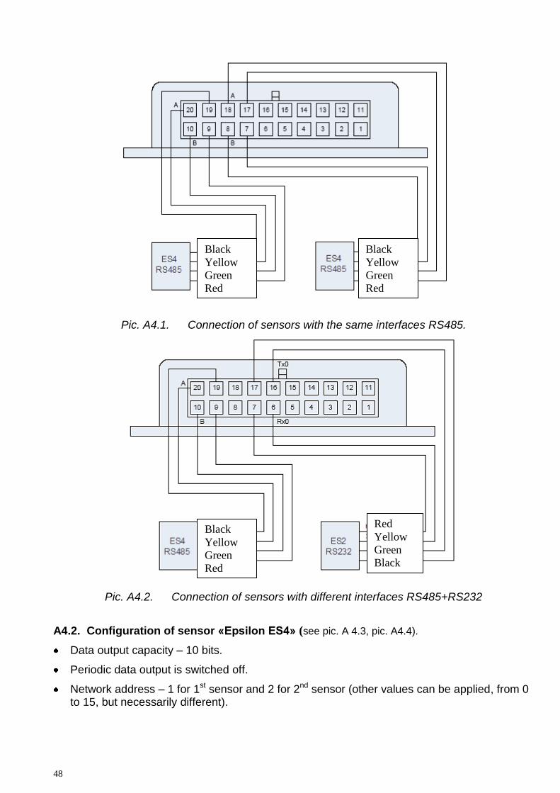
You can connect two sensors with the same interfaces RS485 (pic.A4.1) or different interfaces RS485 or RS232 (Pic. A4.2) to connector MF-20F on the concentrator’s body. To connect three or more sensors to concentrators DALCON cascading connection is used. (see afore-mentioned manual).
48
Pic. A4.1. Connection of sensors with the same interfaces RS485.
Pic. A4.2. Connection of sensors with different interfaces RS485+RS232
A4.2. Configuration of sensor «Epsilon ES4» (see pic. A 4.3, pic. A4.4).
Data output capacity – 10 bits.
Periodic data output is switched off.
Network address – 1 for 1st sensor and 2 for 2nd sensor (other values can be applied, from 0 to 15, but necessarily different).
Black
Yellow
Green
Red
Red
Yellow
Green
Black
Black
Yellow
Green
Red
Black
Yellow
Green
Red

EPSILON ES2,ES4
49
Before connection to DALCON sensors must pass the calibration in accordance with Appendix 1.
A4.3. Configuration of concentrator DALCON (see Pic. A4.5, Pic. A4.6).
Periodic data output - optionally.
Sensor 1 – ask.
Sensor 2 – ask.
You have to install network addresses of sensors in accordance with paragraph A.4.2.
Pic A4.5. Typical DALCON configuration for devices using a digital protocol.

50
Pic. A4.6. A typical DALCON configuration for devices using a text protocol
The value of tank volume should be set a little bit higher than real (for example, 1000 l when the real volume of the tank is 900 l). This is due to calibration table – there must be a point corresponding to the value of code equal to 1023. In the case of FLS LLS, this point always corresponds to a full tank, and in case of FLS "Epsilon" value of the code for a full tank does not reach this point.
A4.4. Entry of calibration table (see pic. A4.7, pic. A4.8).
For empty tank 2 values of code are entered: 0 (automatic) and the value got during the calibration (for latter you have to establish the fuel volume of 1 l). Next, values from a calibration table are entered until the code value for a full tank. Next, you have to enter a value of the tank volume, set earlier, and the value of the code for it, equal to 1023. Conversion level table is stored in memory of DALCON by pressing “Record conversion level table”
Pic. A4.7. Entry of calibration table for the 1st sensor.
Automatically
set zero value
Initial value of
fuel level code
Relative tank
volume for code
1023
Real tank’s
volume

EPSILON ES2,ES4
51
Pic. A4.8. Entry of calibration table for the 2nd sensor.
To use all the settings, you need to switch off and restart DALCON.
52
Appendix 5
CONNECTION OF SENSORS ES4 TO ONBOARD MONITORING
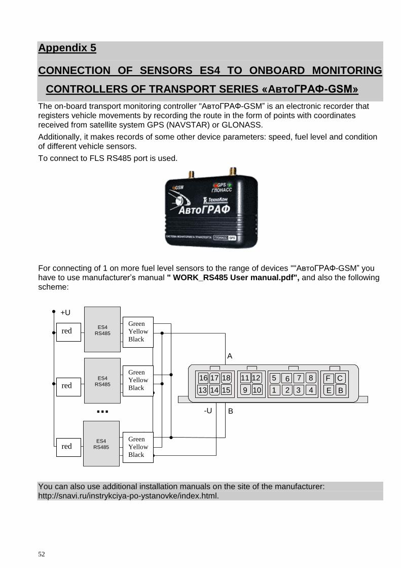
CONTROLLERS OF TRANSPORT SERIES «AвтоГРАФ-GSM»
The on-board transport monitoring controller "AвтоГРАФ-GSM” is an electronic recorder that registers vehicle movements by recording the route in the form of points with coordinates received from satellite system GPS (NAVSTAR) or GLONASS.
Additionally, it makes records of some other device parameters: speed, fuel level and condition of different vehicle sensors.
To connect to FLS RS485 port is used.
For connecting of 1 on more fuel level sensors to the range of devices ""AвтоГРАФ-GSM” you have to use manufacturer’s manual " WORK_RS485 User manual.pdf", and also the following scheme:
ES4
RS485
черный
зеленый
желтыйкрасный
ES4
RS485
черный
зеленый
желтыйкрасный
ES4
RS485
черный
зеленый
желтыйкрасный
...
+U
16 17 18 11 12 5 6 7 8 F C
13 14 15 9 10 1 2 3 4 E B
A
B-U
You can also use additional installation manuals on the site of the manufacturer: http://snavi.ru/instrykciya-po-ystanovke/index.html.
red
red
red
Green
Yellow
Black
Green
Yellow
Black
Green
Yellow
Black

EPSILON ES2,ES4
53
Appendix 6
CONNECTION OF SENSORS ES4 TO ON-BOARD CONTROLLER OF TRANSPORT NAVIGATION "Teletrack TT-221"
Hardware-software complex "Teletrack TT-221" is designed for monitoring of location, speed, fuel level and condition of different vehicle sensors.
To connect to FLS use RS485 port.
For installation and connection of FLS with onboard controller connector "Teletrack" on the connecting cable we set (after installation) a corresponding answer connector supplied with the control unit set.
Also, you should use the manual of "Wireless terminal of subscriber system TELETRACK. Manual of onboard equipment installation" and the following scheme:
ES4
RS485
черный
зеленый
желтый
красный
Depending on your sensors board that are part of the system Teletrack to the control unit 1 or 2 FLS can be connected, with the capacity of 10 or 12 bits.
(see the above-mentioned manual).
Black
Green
Yellow
Red

54
Appendix 7
CONNECTION OF SENSORS ES2 TO TRANSPORT MONITORING
APPLIANCE "IntelliTrac A1"
Device "IntelliTrac A1" is designed for monitoring a vehicle in real time, measurements of traveled distance, arrival time etc.
To connect to FLS use RS232 port.
To connect FLS to "IntelliTrac A1" you have to use service manual "IntelliTrac A1 series User Guide" and following scheme:
ES2
RS232 черный
зеленый
желтый
красный
3
2 4 2
3
4
5
8
9
6 10 2
3
4
5
86
According to manufacturer’s manual for Intellitrack A1 for connection to FLS you have to make next settings with help of the program HyperTerminal:
1) Check the connection speed to FLS with help of RS-232 and set 19200 bit/s:
At$baud?
At$baud=<Port ID>, <Speed>,
<Port ID> 1 -Serial port 1
<Speed> 0- by default 57600bps
Green
Red
Black
Yellow

EPSILON ES2,ES4
55
1-9600bps
2-19200bps
3-38400bps
4 -57600bps
At$baud=1,2
2. Set the data reading from the FLS
At$fuel=<Option>, <Time>,< Frequency >, <Temperature in degrees of centigrade>,<Level>
<Option> 0-prohibited, 1- allowed
<Time> Minimal time in seconds in the range of 1...65535 sec.
<Frequency>, < Temperature in degrees of centigrade>,<Level> -fuel data, fuel volume range of 0...1024
Example: At$fuel=1,60 –to set data reading from FLS every 60 seconds.
Fuel data comes in a standard protocol Intellitrac A1 according to the settings, as additional 6 bytes
<Asynchronous send>+<Fuel data>
Using the "IntelliTrac A1" with one FLS it is necessary during sensor’s configuration to set the text format of the data.
Using the "IntelliTrac A1" with the concentrators of sensors "DALCON" (see Appendix 4) you have to install a text format of the data during the configuration of DALCON (see Picture A4.6).
You must also coordinate the exchange speed on the serial port in one of the ways:
-either set in the sensor exchange speed equal to the exchange speed in "IntelliTrac A1" (see Picture A4.3)
-or set it in "IntelliTrac A1" by command AT$BAUD with a parameter equal to exchange speed in the sensor or in DALCON.
To enable transfer of data about the level of fuel in "IntelliTrac A1", use the command AT$FUEL.

56
Appendix 8
CONNECTION OF SENSORS ES2 TO TRANSPORT MONITORING
APPLIANCE Teltonika MF4100(4200)
"Teltonika FM4100 (FM4200)" is a GPS and GSM terminals, capable to determine the coordinates of a vehicle, to get the information from the sensors and transfer it to GSM networks. To connect FLS use RS232 port.
Configuration of Teltonika FM4100 (FM4200) and firmware
To use FLS "EPSILON" you need special firmware and the configurator, which can be supplied by agents or dealers of Teltonika (version Firmware v.5.00.03 and M42.Configurator.Ver.1.5.0.20 or later).
Fuel and temperature level are set from the menu "I/O" of the configurator (see Pic. A8.1):
IO ID28 –fuel level;
IO ID29 – fuel temperature.
Pic. A8.1

EPSILON ES2,ES4
57
IO Configuration of levels of fuel or temperature are shown in Pic. A 8.2
Pic. A8.2
Procedure of FLS "EPSILON" calibration
1) Start the program "eS Install" (see details in Appendix 1)
2) On the tab "Sensor’s general options" set following parameters of a measuring head:
"Network address of device": 1
"Repeat interval": 1
"Capacity": 10 bit
"Enable periodic output": activate
"Enable text format": off
"Exchange speed on UART: 19200
Pic. A8.3

58
6) Then you need to perform calibration in accordance with Appendix 1.
Connection of the sensor to FM4100 (4200)
When configuration is complete, the sensor can be connected to models "Teltonika FM4100" or "Teltonika FM4200" according to Pic. A8.4:
Pic. A8.4
Connector
RJ-45
Red
Black
Yellow
Green
EPSILON ES2,ES4
59
Appendix 9
Connecting sensors to the subscriber terminal ES2
M2M-Cyber GLX
M2M-Cyber GLX-subscriber terminal operating satellite systems GLONASS and GPS, as well as compatible with the data channels GSM (GPRS).
M2M-Cyber GLX is a multifunctional navigation and communication avionics systems to monitor and control traffic, intended for transmission via GSM (GPRS) in the telematics server, and users of information control centers on the movement of the vehicle, data from its attached peripherals as well as providing two-way communication between vehicles and control centers of users.
To connect the sensor to the fuel, "M2M-Cyber GLX" should take leadership of the "Terminal subscriber's GSM / GLONASS / GPS" m2m-cYBER glx ". Manual. MDAV.464428.000 ER."
To connect the FLS port is RS485 or RS232. You can connect a FLS.
Configuration of M2M-Cyber GLX and firmware
Configuring the M2M-Cyber GLX is from any terminal program (eg, Hyper Terminal) according to the manual for M2M-Cyber GLX ”AVST.464468.002RE2_Manual for exploitation and configuration”.
In order to provide M2M-Cyber GLX with the FLS «EPSILON» need to configure a custom UART and set the parameters of the service to work with FLS.
Configuration of custom UART.
Mode: RS232 for use with FLS ES2 and RS485 for use with FLS ES4.
Team: UART MODE = 0 - mode RS232, UART MODE = 1 - mode RS485.
Test run: UART MODE?
Data Rate: must match the speed set in the FLS (setting manufacturer - 19,200 bit / s).
60
Team: UART SPEED = 19 200
Test run: UART SPEED?
Data word length - 8 bits.
Team: UART WORD = 8
Test run: UART WORD?
Number of stop bits - 1.
Team: UART STOP = 1
Test run: UART STOP?
Parity is not checked.
Team: UART PARITY = 0
Test run: UART PARITY?
Flow control - no control.
Team: UART FLOW = 0
Test run: UART FLOW?
Start and stop bytes - does not matter.
After completing the configuration, the user must enable the port to receive data from a command UART USE = 1. Upon completion of this command changed settings will be applied to the device.
Configuration Service with FLS.
Type of service data - 1 or 4 (4 is recommended).
Team: LLS TYPE = 1 or LLS TYPE = 4
Test run: LLS TYPE?
EPSILON ES2,ES4
61
Averaging time data - 15 ... 60 c or off (depending on the particular problem).
Team: LLSAVER TIME = 15
Test run: LLSAVER TIME?
Notice. Disabling the averaging or the installation is too small values of the averaging time is the accumulation of redundant data, which can lead to increased consumption of GPRS traffic on their gear!
Time delay start of measurement and data - 3 ... 5.
Team: LLSSTART DELAY = 3
Test run: LLSSTART DELAY?
Notice. EPSILON FLS starts to give valid data at 1 ... 2 seconds after power-up.
Termination of the waiting time of packets from the fuel gauge - 30 seconds (the default).
Team: LLSFINISH DELAY = 30
Test run: LLSFINISH DELAY?
The calibration procedure FLS "EPSILON"
1) Run "eS Install" (see details in Appendix 1)
2) On the tab "General Options sensor", set the following parameters of the measuring head:
• "The network address of the device": 1
• "Retry interval": 1
• "Bit" 10-bit
• "On. Periodically issue": the regime is included for LLS TYPE = 1 and has no value for the mode LLS TYPE = 4
• "On. Text format": disabled
• "The rate of exchange on the UART": 19200 bits / s (may be modified depending on the problem under the condition of equality of exchange rates in the FLS and device traffic monitoring)

62
6) Next, you need to perform calibration procedures and calibration in accordance with Annex 1.
Connect and check.
Once configuration is complete, the sensor can be attached to the device "M2M-Cyber GLX" according to the following drawings:
ES2
RS232
черный
зеленый
желтый
красный 5
9
4
8
2
6
3 1
10
+12V
ES4
RS485
зеленый
желтый
черный
красный 5
9
4
8
2
6
3 1
10
+12V
Check can be done by monitoring the debug information output to the terminal program used to configure the device "M2M-Cyber GLX". If the connection is properly configured and the data from the FLS will be prepared for shipment in the terminal window will be issued from time to time information of the form:
9 Receive byte from user UART at 11:37:41 22/05/12
3E 8F 01 July 18 01 0F 00 4F
red
black
yellow
green
red
black
green yellow
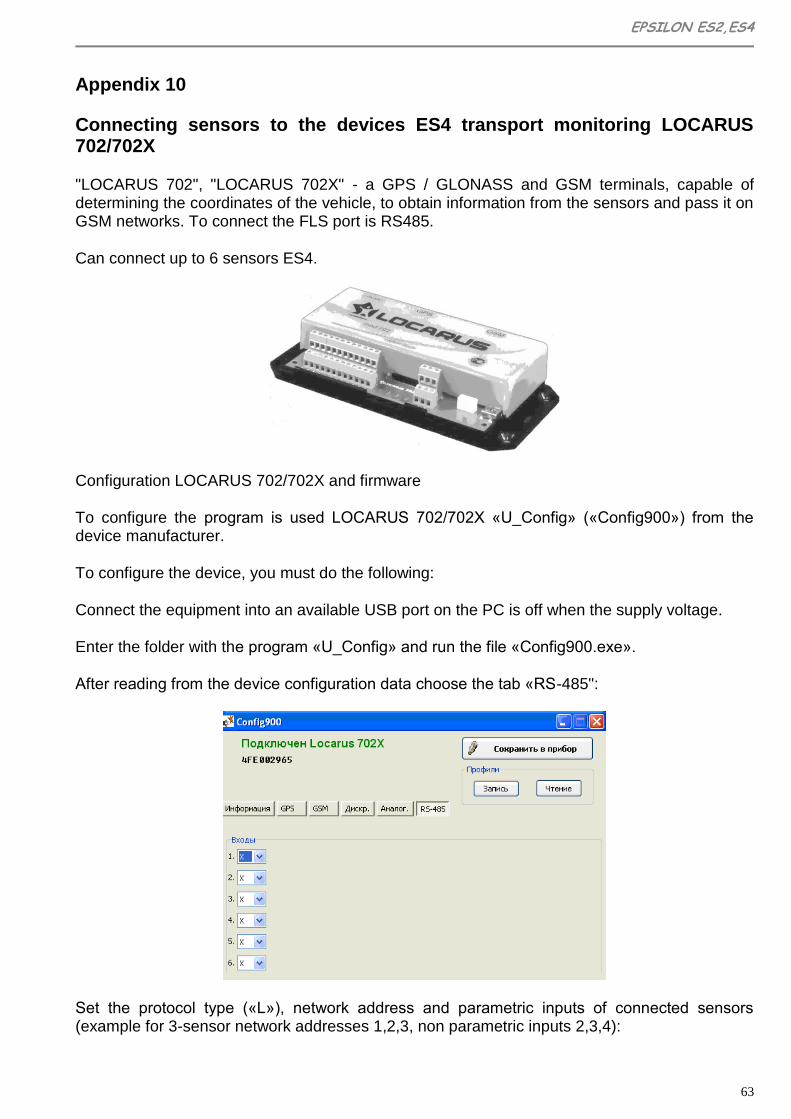
EPSILON ES2,ES4
63
Appendix 10
Connecting sensors to the devices ES4 transport monitoring LOCARUS 702/702X
"LOCARUS 702", "LOCARUS 702X" - a GPS / GLONASS and GSM terminals, capable of determining the coordinates of the vehicle, to obtain information from the sensors and pass it on GSM networks. To connect the FLS port is RS485.
Can connect up to 6 sensors ES4.
Configuration LOCARUS 702/702X and firmware
To configure the program is used LOCARUS 702/702X «U_Config» («Config900») from the device manufacturer.
To configure the device, you must do the following:
Connect the equipment into an available USB port on the PC is off when the supply voltage.
Enter the folder with the program «U_Config» and run the file «Config900.exe».
After reading from the device configuration data choose the tab «RS-485":
Set the protocol type («L»), network address and parametric inputs of connected sensors (example for 3-sensor network addresses 1,2,3, non parametric inputs 2,3,4):

64
Notice. Sensor Network addresses must necessarily be different (the program «Config900» it does not control). Network addresses are chosen from the range 0 ... 5.
Save Configuration button. If necessary, you can also save the configuration to a file button.
The calibration procedure FLS "EPSILON"
Run the program "eS Install" (see details in Appendix 1)
On the tab "General Options sensor", set the following parameters of the measuring head:
• "The network address of the device" from 0 to 5, is unique for each sensor
• "Repeat Interval": it does not matter
• "Bit" 10-bit
• "On. Periodically issue": disabled
• "On. Text format": disabled
• "The rate of exchange on the UART": 19200 bits/s
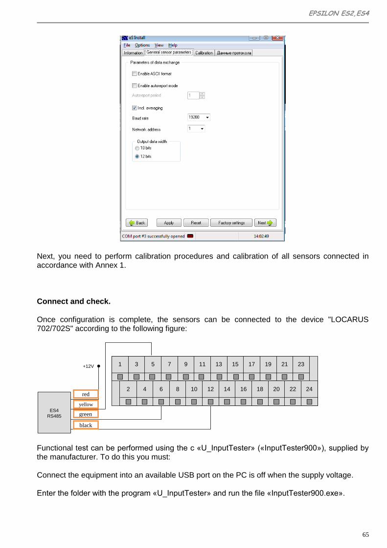
EPSILON ES2,ES4
65
Next, you need to perform calibration procedures and calibration of all sensors connected in accordance with Annex 1.
Connect and check.
Once configuration is complete, the sensors can be connected to the device "LOCARUS 702/702S" according to the following figure:
1 3 5 7 9 11
2 4 6 8
13 15 17 19 21 23
10 12 14 16 18 20 22 24
ES4
RS485
желтый
черный
зеленый
красный
+12V
Functional test can be performed using the c «U_InputTester» («InputTester900»), supplied by the manufacturer. To do this you must:
Connect the equipment into an available USB port on the PC is off when the supply voltage.
Enter the folder with the program «U_InputTester» and run the file «InputTester900.exe».
red
yellow
green
black

66
Turn on the unit. Check the condition of parametric inputs assigned to the connected sensors

EPSILON ES2,ES4
67
Attention!
The manufacturer is not responsible for product availability in case of non-compliance of requirements of this service manual, unauthorized service and repair; if device has damage or traces of opening of head’s body, mechanical damage of the probe or the interface cable, as well as traces of corrosive acids, open flame, high voltage, lightning strikes or other natural
factors.
Address of service center
04074, Ukraine, Kyiv, 2/6 Novozabarskaya street,
Telephone.: (+38044) 206-69-79, 206-42-34 Fax: (+38044) 206-42-36
http://autovision.com.ua http://www.rcs. kiev.ua
v. 120203