Embed Size (px)
DESCRIPTION
EPRI start up program
Citation preview
7/18/2019 EPRI Start Up, Lay Up & Shut Down Guidelines for Chemist
http://slidepdf.com/reader/full/epri-start-up-lay-up-shut-down-guidelines-for-chemist 1/256
7/18/2019 EPRI Start Up, Lay Up & Shut Down Guidelines for Chemist
http://slidepdf.com/reader/full/epri-start-up-lay-up-shut-down-guidelines-for-chemist 2/256
DISCLAIMER OF WARRANTIES AND LIMITATION OF LIABILITIES
THIS REPORT WAS PREPARED BY THE ORGANIZATION(S) NAMED BELOW AS AN ACCOUNT OF WORKSPONSORED OR COSPONSORED BY THE ELECTRIC POWER RESEARCH INSTITUTE, INC. (EPRI).NEITHER EPRI, ANY MEMBER OF EPRI, ANY COSPONSOR, THE ORGANIZATION(S) NAMED BELOW,NOR ANY PERSON ACTING ON BEHALF OF ANY OF THEM:
(A) MAKES ANY WARRANTY OR REPRESENTATION WHATSOEVER, EXPRESS OR IMPLIED, (I) WITHRESPECT TO THE USE OF ANY INFORMATION, APPARATUS, METHOD, PROCESS, OR SIMILAR ITEMDISCLOSED IN THIS REPORT, INCLUDING MERCHANTABILITY AND FITNESS FOR A PARTICULARPURPOSE, OR (II) THAT SUCH USE DOES NOT INFRINGE ON OR INTERFERE WITH PRIVATELY OWNEDRIGHTS, INCLUDING ANY PARTY'S INTELLECTUAL PROPERTY, OR (III) THAT THIS REPORT ISSUITABLE TO ANY PARTICULAR USER'S CIRCUMSTANCE; OR
(B) ASSUMES RESPONSIBILITY FOR ANY DAMAGES OR OTHER LIABILITY WHATSOEVER (INCLUDINGANY CONSEQUENTIAL DAMAGES, EVEN IF EPRI OR ANY EPRI REPRESENTATIVE HAS BEEN ADVISEDOF THE POSSIBILITY OF SUCH DAMAGES) RESULTING FROM YOUR SELECTION OR USE OF THISREPORT OR ANY INFORMATION, APPARATUS, METHOD, PROCESS, OR SIMILAR ITEM DISCLOSED INTHIS REPORT.
ORGANIZATION(S) THAT PREPARED THIS REPORT
Electric Power Research Institute
ORDERING INFORMATION
Requests for copies of this report should be directed to the EPRI Distribution Center, 207 Coggins Drive, P.O. Box23205, Pleasant Hill, CA 94523, (510) 934-4212.
Electric Power Research Institute and EPRI are registered service marks of the Electric Power Research Institute, Inc.EPRI. POWERING PROGRESS is a service mark of the Electric Power Research Institute, Inc.
Copyright © 1998 Electric Power Research Institute, Inc. All rights reserved.
7/18/2019 EPRI Start Up, Lay Up & Shut Down Guidelines for Chemist
http://slidepdf.com/reader/full/epri-start-up-lay-up-shut-down-guidelines-for-chemist 3/256
iii
CITATIONS
This report was prepared by
EPRI3412 Hillview AvenuePalo Alto, CA 94403
This report describes research sponsored by EPRI. It is a corporate document thatshould be cited in the literature in the following manner:
Cycling, Startup, Shutdown, and Layup Fossil Plant Cycle Chemistry Guidelines for Operatorsand Chemists, EPRI, Palo Alto, CA, 1998.TR-107754.

7/18/2019 EPRI Start Up, Lay Up & Shut Down Guidelines for Chemist
http://slidepdf.com/reader/full/epri-start-up-lay-up-shut-down-guidelines-for-chemist 4/256
7/18/2019 EPRI Start Up, Lay Up & Shut Down Guidelines for Chemist
http://slidepdf.com/reader/full/epri-start-up-lay-up-shut-down-guidelines-for-chemist 5/256
v
REPORT SUMMARY
The purity of water and steam is central to ensuring fossil plant component availability
and reliability. This report will assist utilities in developing cycle chemistry guidelines
for all transient operation and shutdown.
Background
EPRI has published four operating guidelines for phosphate treatment, all-volatiletreatment, oxygenated treatment, and caustic treatment. These guidelines encompass
five drum boiler water treatments and three feedwater choices that can provide the
optimum cycle chemistry for each unit. A similar, consistent approach was needed for
startup, shutdown, and layup. Improper shutdown of a unit can lead to pitting, which
is a precursor to major corrosion fatigue and stress corrosion damage in the turbine. It
can also lead to the development of nonprotective oxides on copper alloys in the
feedwater.
ObjectiveTo provide comprehensive guidelines for cycle chemistry during startup, shutdown,
and layup of fossil plants; to provide optimum procedures for the boiler, superheater,
reheater, turbine, and feedwater heaters.
ApproachEPRI developed an initial skeleton of the guidelines that provided the basis for a series
of working group meetings with members of the EPRI Fossil Plant Cycle Chemistry
Group (FPCCG). Following these meetings, EPRI and five of its cycle chemistry
consultants developed a draft document and circulated it to the 40 members of the
FPCCG for review and comment.
ResultsThis guideline provides the final link needed for comprehensive coverage of cycle
chemistry in fossil plants. It provides specific procedures and advice during cycling,
shutdown, startup, and layup for each of the boiler and feedwater treatments and
7/18/2019 EPRI Start Up, Lay Up & Shut Down Guidelines for Chemist
http://slidepdf.com/reader/full/epri-start-up-lay-up-shut-down-guidelines-for-chemist 6/256
vi
covers all major water and steam touched surfaces. The guideline is applicable to drum
boiler units above 600 psi (4.1MPA), once-through subcritical and supercritical boiler
units, units with and without condensate polishers, all-ferrous and mixed metallurgy
feedwater systems, and superheaters, reheaters and turbines.
EPRI Perspective
While most utilities can meet EPRI cycle chemistry guideline limits, a large number of
problem areas have been identified that relate to poor transient (startup/shutdown)
operation and improper layup procedures. Two such important mechanisms are pitting
in unprotected reheaters, which can lead to multiple reheater leaks. and pits on low
pressure turbine blade/disk surfaces in the phase transition zone. A very low
percentage of utilities currently provide shutdown protection to boilers, feedwater
heaters, and turbines. This document will provide the important interfaces between
plant operation, plant shutdown, and transient conditions.
TR-107754
Interest Categories
Fossil steam plant O&M cost reductionFossil steam plant performance optimizationApplied science and technology
KeywordsPower plant availability
Water chemistry
Cycling
Startup
Shutdown
Layup
7/18/2019 EPRI Start Up, Lay Up & Shut Down Guidelines for Chemist
http://slidepdf.com/reader/full/epri-start-up-lay-up-shut-down-guidelines-for-chemist 7/256

7/18/2019 EPRI Start Up, Lay Up & Shut Down Guidelines for Chemist
http://slidepdf.com/reader/full/epri-start-up-lay-up-shut-down-guidelines-for-chemist 8/256
EPRI L icensed M aterial
viii
Section 4 provides information on layup and shutdown considerations common to mostunits: wet and dry layup, and dehumidification for all the major power plantcomponents.
Sections 5-8 deal with specific procedures for cycling, shutdown, startup, and layup for
phosphate treatments, all-volatile treatment, oxygenated treatment and caustictreatment respectively.
7/18/2019 EPRI Start Up, Lay Up & Shut Down Guidelines for Chemist
http://slidepdf.com/reader/full/epri-start-up-lay-up-shut-down-guidelines-for-chemist 9/256
EPRI L icensed M aterial
ix
ACKNOWLEDGMENTS
The authors of these guidelines:
R. B. Dooley, EPRIA. Aschoff, EPRI ConsultantM. Ball, EPRI ConsultantA. Bursik, EPRI ConsultantO. Jonas, EPRI Consultant of Jonas Inc.
andF. Pocock, EPRI Consultant
acknowledge that the two earlier drafts of this guideline were reviewed by the 41members of the Fossil Plant Cycle Chemistry Group (FPCCG). The authors furtheracknowledge the contributions from the following members of the FPCCG:
B. Conlin ESKOMD. Goldstrohm Salt River ProjectA. Howell New Century EnergiesD. E. Hubbard American Electric Power
A. Lindberg Commonwealth Edison J. Matthews Duke PowerV. Mrasek Public Service Company of OklahomaK. J. Shields Sheppard D. Powell AssociatesW. Urion Connectiv
During the preparation of these guidelines two Target 51 member utilities alsoprovided extensive documentation on their layup experiences which arecomplementary to the procedures in the guidelines:
Iberdrola SpainEcogen Energy Australia
This report was word processed by Lorrain Sargent of Pacific Publications, and all thefigures were drawn by Marilyn Winans of the EPRI Graphics Office.

7/18/2019 EPRI Start Up, Lay Up & Shut Down Guidelines for Chemist
http://slidepdf.com/reader/full/epri-start-up-lay-up-shut-down-guidelines-for-chemist 10/256
7/18/2019 EPRI Start Up, Lay Up & Shut Down Guidelines for Chemist
http://slidepdf.com/reader/full/epri-start-up-lay-up-shut-down-guidelines-for-chemist 11/256
EPRI L icensed M aterial
xi
CONTENTS
1 INTRODUCTION ................................................................................................................. 1-1
1.1 OVERVIEW OF THE EPRI FOSSIL PLANT CYCLE CHEMISTRY PROGRAM.......... 1-1
Volatility of Salts in Steam Cycles................................................................................... 1-2
Phosphate Chemistry/Hideout/Corrosion ........................................................................ 1-4
Deposition and Chemical Cleaning ................................................................................. 1-6Steam, Chemistry and Corrosion in the Phase Transition Zone (PTZ)............................ 1-6
1.2 EPRI FOSSIL PLANT GUIDELINES AND MANAGEMENT APPROACHES FORCYCLE CHEMISTRY.......................................................................................................... 1-7
1.3 NEED AND DEVELOPMENT FOR CYCLING/SHUTDOWN/STARTUP/LAYUPGUIDELINES...................................................................................................................... 1-9
1.4 OBJECTIVES OF THESE GUIDELINES ................................................................... 1-10
1.5 SCOPE OF THESE GUIDELINES............................................................................. 1-11
1.6 REFERENCES .......................................................................................................... 1-11
2 METALLURGICAL, DESIGN, AND OPERATING CONSIDERATIONS.............................. 2-1
2.1 INTRODUCTION.......................................................................................................... 2-1
Impurity Generation, Transport, and Corrosion Effects................................................... 2-3
Steam Cycle Materials and Their Properties................................................................... 2-8
Material Properties .......................................................................................................... 2-9
2.2 STEAM CYCLE COMPONENT CORROSION AND DEPOSITS ................................. 2-9
Basics of Material Corrosion ........................................................................................... 2-9
Cycle Component Damage Mechanisms ...................................................................... 2-17
2.3 PREBOILER SYSTEMS - ALL FERROUS VS. MIXED METALLURGY .................... 2-21
All-Ferrous Feedwater Systems(3, 4)
................................................................................ 2-22
Mixed Metallurgy Feedwater Systems (Copper Containing)(3, 4, 22, 28)
................................ 2-24
Copper Transport .......................................................................................................... 2-25
2.4 PRIORITIES FOR TRANSIENT OPERATION........................................................... 2-26
7/18/2019 EPRI Start Up, Lay Up & Shut Down Guidelines for Chemist
http://slidepdf.com/reader/full/epri-start-up-lay-up-shut-down-guidelines-for-chemist 12/256
EPRI L icensed M aterial
xii
2.5 EFFECTS OF STEAM CYCLE DESIGN AND OPERATION ..................................... 2-29
Drum Boiler vs. Once-through Boiler Units(7-12)
............................................................... 2-30
Sliding Pressure Operation(17,39-42)
................................................................................... 2-30
Boiler Concerns(15-17,25,39,40,43-46).............................................................................................. 2-30
Turbine(18,42,49,50)................................................................................................................... 2-33
Turbine Bypass Systems(43,49.50)
.......................................................................................... 2-38
Feedwater System Cleanup Loops(14,45,46,52,53,54) ................................................................... 2-39
Condensate Filtering and Polishing(15,45,54,67)........................................................................ 2-41
Air Inleakage and Deaeration(15,45,53-61)
................................................................................. 2-41
Condenser Deaeration .................................................................................................. 2-47
2.6 ALTERNATIVE WATER TREATMENT CHEMICALS(3,63,64) ......................................... 2-47
2.7 REFERENCES AND BIBLIOGRAPHY FOR SECTION 2 .......................................... 2-49
3 GENERAL ASPECTS COMMON TO MOST UNITS ........................................................... 3-1
3.1 DEFINITIONS .............................................................................................................. 3-1
Cycling ............................................................................................................................ 3-1
Duration of Shutdown...................................................................................................... 3-1
Forced Shutdown............................................................................................................ 3-2
System Failure but no Equipment Failure ................................................................... 3-3
Major Equipment Failure ............................................................................................. 3-3
3.2 USE OF POLISHERS AND CONDENSATE FILTRATION .......................................... 3-3
Condensate Polishing and/or Filtration(1b)
........................................................................ 3-3
Makeup Water Treatment................................................................................................ 3-3
3.3 MONITORING IMPORTANCE AND REQUIREMENTS............................................... 3-4
Sampling and Monitoring ................................................................................................ 3-4
Sampling Problems ......................................................................................................... 3-4
3.4 MAJOR CHEMICAL TRANSIENT................................................................................ 3-5
Chemical Transients and Equipment Failures................................................................. 3-6
3.5 MINIMIZATION OF AIR IN-LEAKAGE......................................................................... 3-7
3.6 CORRECTIVE ACTIONS............................................................................................. 3-8
3.7 HOW TO USE THE PRESENT EPRI GUIDELINES FOR CYCLINGOPERATION....................................................................................................................... 3-8
Drum Units ...................................................................................................................... 3-9
Once-Through Units...................................................................................................... 3-10
7/18/2019 EPRI Start Up, Lay Up & Shut Down Guidelines for Chemist
http://slidepdf.com/reader/full/epri-start-up-lay-up-shut-down-guidelines-for-chemist 13/256
EPRI L icensed M aterial
xiii
3.8 OPERATING PROCEDURES.................................................................................... 3-10
3.9 ENVIRONMENTAL CONSIDERATIONS ................................................................... 3-10
3.10 REFERENCES ........................................................................................................ 3-11
4 SHUTDOWN AND LAYUP CONSIDERATIONS COMMON TO MOST UNITS................... 4-14.1 INTRODUCTION.......................................................................................................... 4-1
4.2 LAYUP PRACTICES.................................................................................................... 4-2
Short-term vs. Longterm Layup....................................................................................... 4-3
4.3 WET LAYUP (12-15) ......................................................................................................... 4-8
4.4 DRY LAYUP USING DEHUMIDIFIED AIR................................................................... 4-9
4.5 FEEDWATER HEATERS, CONDENSER, REHEATER AND TURBINE.................... 4-14
Turbine.......................................................................................................................... 4-15
Feedwater Side of Condensers and Feedwater Heaters .............................................. 4-16Shell Side Feedwater Heaters....................................................................................... 4-16
Superheater .................................................................................................................. 4-16
Deaerator and Storage Tank......................................................................................... 4-17
4.6 LAYUP MONITORING............................................................................................... 4-17
4.7 ENVIRONMENTAL CONSIDERATIONS ................................................................... 4-17
4.8 ROAD MAP FOR SHUTDOWN AND LAYUP ............................................................ 4-18
4.9 REFERENCES .......................................................................................................... 4-22
5 PHOSPHATE TREATED DRUM UNITS.............................................................................. 5-1
5.1 INTRODUCTION.......................................................................................................... 5-1
5.2 CURRENT NORMAL OPERATING GUIDELINES....................................................... 5-2
5.3 STARTUP PROCEDURES........................................................................................ 5-10
Road Map ..................................................................................................................... 5-11
5.4 CYCLING AND PEAKING UNITS.............................................................................. 5-12
5.5 SHUTDOWN PROCEDURES.................................................................................... 5-12
Road Map ..................................................................................................................... 5-14
5.6 MIXED METALLURGY SYSTEMS ............................................................................ 5-16
5.7 CORRECTIVE ACTIONS........................................................................................... 5-17
5.8 LAYUP....................................................................................................................... 5-17
5.9 REFERENCES .......................................................................................................... 5-18
6 ALL-VOLATILE TREATMENT ............................................................................................ 6-1
7/18/2019 EPRI Start Up, Lay Up & Shut Down Guidelines for Chemist
http://slidepdf.com/reader/full/epri-start-up-lay-up-shut-down-guidelines-for-chemist 14/256
EPRI L icensed M aterial
xiv
6.1 INTRODUCTION.......................................................................................................... 6-1
6.2 ONCE-THROUGH UNITS............................................................................................ 6-2
Current Guidelines .......................................................................................................... 6-2
Startup ............................................................................................................................ 6-2
Shutdown........................................................................................................................ 6-7
Cycling and Peaking ..................................................................................................... 6-10
Layup ............................................................................................................................ 6-11
6.3 DRUM BOILERS WITH ALL-FERROUS FEEDWATER HEATING SYSTEMS.......... 6-11
Current Guidelines ........................................................................................................ 6-11
Startup .......................................................................................................................... 6-18
Shutdown...................................................................................................................... 6-22
Cycling and Peaking ..................................................................................................... 6-26
Layup ............................................................................................................................ 6-26
6.4 DRUM UNITS WITH MIXED METALLURGY FEEDWATER HEATING SYSTEMS... 6-27
Current Guidelines ........................................................................................................ 6-28
Startup .......................................................................................................................... 6-28
Shutdown...................................................................................................................... 6-32
Cycling and Peaking ..................................................................................................... 6-36
Layup ............................................................................................................................ 6-36
6.5 REFERENCES .......................................................................................................... 6-36
7 OXYGENATED TREATMENT............................................................................................. 7-1
7.1 INTRODUCTION.......................................................................................................... 7-1
7.2 ALL-FERROUS CYCLES WITH ONCE-THROUGH BOILERS.................................... 7-2
Current Normal Operating Guidelines ............................................................................. 7-2
Startup Procedures ......................................................................................................... 7-4
Shutdown Procedures..................................................................................................... 7-7
Short-Term Shutdown. ................................................................................................ 7-8
Longterm Shutdown.................................................................................................... 7-9
Emergency Shutdown. .............................................................................................. 7-10
Shutdown as a Result of a Serious Chemistry Excursion.......................................... 7-10
Cycling and Peaking Operation(3-7)
................................................................................. 7-10
Layup Practices............................................................................................................. 7-11
7.3 ALL-FERROUS CYCLES WITH DRUM BOILERS..................................................... 7-12
7/18/2019 EPRI Start Up, Lay Up & Shut Down Guidelines for Chemist
http://slidepdf.com/reader/full/epri-start-up-lay-up-shut-down-guidelines-for-chemist 15/256
EPRI L icensed M aterial
xv
Current Normal Operating Guidelines ........................................................................... 7-12
Startup Procedures ....................................................................................................... 7-14
Shutdown Procedures................................................................................................... 7-19
Short-Term Shutdown. .............................................................................................. 7-19
Longterm Shutdown.................................................................................................. 7-20
Emergency Shutdown. .............................................................................................. 7-21
Shutdown as a Result of a Serious Chemistry Excursion.......................................... 7-22
Cycling and Peaking Operation..................................................................................... 7-23
Layup Practices............................................................................................................. 7-23
7.4 REFERENCES .......................................................................................................... 7-24
8 CAUSTIC TREATMENT FOR DRUM BOILERS ................................................................. 8-1
8.1 INTRODUCTION.......................................................................................................... 8-18.2 ALL-FERROUS FEEDWATER HEATING SYSTEMS.................................................. 8-2
Current Guidance Document........................................................................................... 8-2
Startup ............................................................................................................................ 8-2
Shutdown........................................................................................................................ 8-5
Cycling and Peaking ....................................................................................................... 8-5
Layup .............................................................................................................................. 8-7
8.3 MIXED METALLURGY FEEDWATER HEATING SYSTEMS ...................................... 8-7
Current Guidelines .......................................................................................................... 8-9
Startup ............................................................................................................................ 8-9
Shutdown...................................................................................................................... 8-11
Cycling and Peaking ..................................................................................................... 8-12
Layup ............................................................................................................................ 8-12
8.4 REFERENCES .......................................................................................................... 8-12

7/18/2019 EPRI Start Up, Lay Up & Shut Down Guidelines for Chemist
http://slidepdf.com/reader/full/epri-start-up-lay-up-shut-down-guidelines-for-chemist 16/256
7/18/2019 EPRI Start Up, Lay Up & Shut Down Guidelines for Chemist
http://slidepdf.com/reader/full/epri-start-up-lay-up-shut-down-guidelines-for-chemist 17/256
EPRI L icensed M aterial
xvii
LIST OF FIGURES
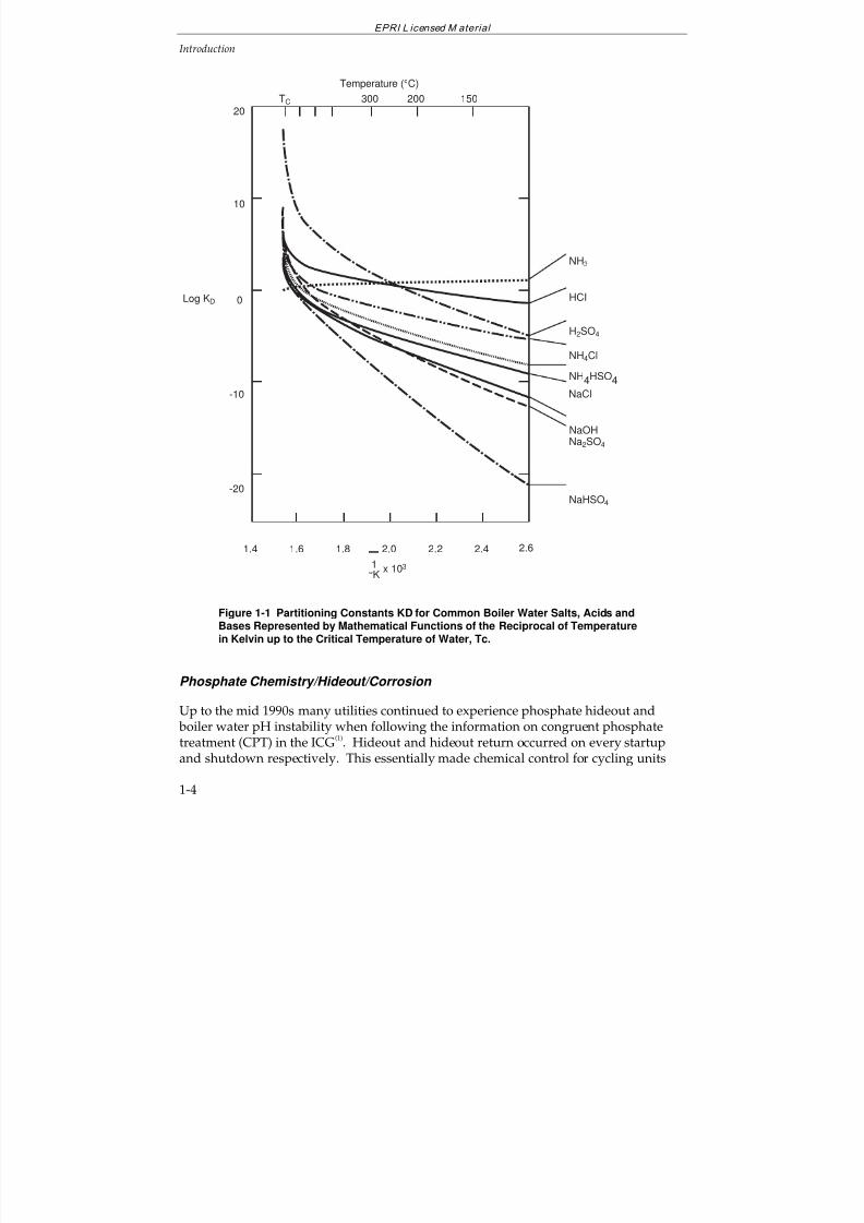
Figure 1-1 Partitioning Constants KD for Common Boiler Water Salts, Acids and BasesRepresented by Mathematical Functions of the Reciprocal of Temperature inKelvin up to the Critical Temperature of Water, Tc.......................................................... 1-4
Figure 2-1 Three supports for reliable cycling operation........................................................ 2-2
Figure 2-2 Typical water chemistry and corrosion effects of layup, startup and cyclingfor a drum boiler cycle..................................................................................................... 2-4
Figure 2-3 Sources of contaminants enhanced by cycling operation and examples ofengineering solutions. ..................................................................................................... 2-5
Figure 2-4 Mollier diagram for a fossil cycle........................................................................... 2-6
Figure 2-5 Potential - pH diagram for carbon steel in 300 °C water(19)
.................................. 2-11
Figure 2-6 Corrosion of mild steel and solubility of magnetite at 300°C, showingcorrosion rate laws
(15,20.21)................................................................................................ 2-12
Figure 2-7 Potential - pH diagram for copper in ammonia solutions at 25°C(22)
.................... 2-13
Figure 2-8 Average copper release as a function of pH....................................................... 2-14
Figure 2-9 Effect of pH on steady state release rates for 90Cu/10Ni and 70Cu/30Niexposed to ammonia solutions containing 8-21 µg/kg oxygen, flowing at ~1ft/s
(0.3m/s) and at a temperature of 35° - 38°C
(22)
.............................................................. 2-15Figure 2-10 Corrosion fatigue diagram for NiCrMoV LP turbine disk and rotor steel18 ........ 2-16
Figure 2-11 Stress corrosion of NiCrMoV disk steel vs. yield strength for "good" waterand steam(18) .................................................................................................................. 2-17
Figure 2-12 The effect of pH on iron and copper concentration at the economizer inlet.Source: D. Frey, Mechanics of Corrosion Product Formation and Transport(14) ............ 2-22
Figure 2-13 Calculated and measured HP rotor temperatures - startup .............................. 2-34
Figure 2-14 Turbine fatigue index vs. temperature change and time(51)
............................... 2-37
Figure 2-15 Turbine valves for partial arc and full arc admission......................................... 2-37
Figure 2-16 Rotor thermal stress as a function of time with sliding pressure. Initial
throttle to metal temperature difference = +50°F, throttle temperature ramp =200°F/h, loading rate = 2% per minute.......................................................................... 2-37
Figure 2-17 Turbine bypass system..................................................................................... 2-39
Figure 2-18 Condensate/feedwater cleanup loops(46)
........................................................... 2-40
Figure 2-19 Expected dissolved oxygen at the deaerator outlet vs. load for tray andspray deaerators ........................................................................................................... 2-43
Figure 2-20 Condenser deaerating capacity with and without retrofitted devices(62)
............. 2-44
7/18/2019 EPRI Start Up, Lay Up & Shut Down Guidelines for Chemist
http://slidepdf.com/reader/full/epri-start-up-lay-up-shut-down-guidelines-for-chemist 18/256
EPRI L icensed M aterial
xviii
Figure 2-21 Cycle iron concentration during a cold startup for two layup practices(62)
.......... 2-45
Figure 2-22 Effect of air-saturated makeup water on condensate oxygen level(59)
............... 2-46
Figure 3-1 Metals Concentrations in Feedwater During Startup Operations(9,10) ..................... 3-5
Figure 4-1 Nitrogen blanketing of a drum boiler showing the nitrogen connections(12)
. .......... 4-7
Figure 4-2 Corrosion Rate of Steel Relative to Humidity of Air ............................................ 4-10Figure 4-3 Rotary Desiccant Dehumidifier
(17)........................................................................ 4-11
Figure 4-4 Block Diagram of Dehumidifier Steam/Feed Cycle(18)
.......................................... 4-12
Figure 4-5 Steamside Dehumidification Flow(19)
................................................................... 4-13
Figure 4-6 Turbine dry layup using dehumidified air(23)
......................................................... 4-16
Figure 4-7 Dry layup of 107 MW turbine showing measured values of temperature(°F/°C) and air humidity ................................................................................................. 4-16
Figure 4-8 Road Map to Develop Shutdown and Layup Guidelines Common to MostUnits.............................................................................................................................. 4-18
Figure 5-1 Older Forms of Phosphate Treatment .................................................................. 5-3
Figure 5-2 Schematic of Operating Ranges of Boiler Water on Equilibrium PhosphateTreatment (EPT), Congruent Phosphate Treatment (CPT) and PhosphateTreatment (PT)
(1). The CPT is shown to its maximum Na:PO
4 molar ratio of 2.8; the
normal operating range is below the Na:PO4 molar ratio of 2.6....................................... 5-4
Figure 5-3 Cycle Chemistry Diagram for a Drum Unit on Equilibrium PhosphateTreatment (Plants With Reheat)—Core Parameters Marked. ......................................... 5-5
Figure 5-4 Equilibrium Phosphate Treatment: Boiler Water Sodium vs. OperatingPressure (Plants With Reheat)........................................................................................ 5-6
Figure 5-5 Equilibrium Phosphate Treatment: Boiler Water Chloride vs. OperatingPressure (Plants With Reheat)........................................................................................ 5-7
Figure 5-6 Equilibrium Phosphate Treatment: Boiler Water Sulfate vs. OperatingPressure (Plants With Reheat)........................................................................................ 5-8
Figure 5-7 Equilibrium Phosphate Treatment: Boiler Water Silica vs. OperatingPressure (Plants With Reheat)........................................................................................ 5-9
Figure 5-8 Road Map for Startup of PT or EPT Units .......................................................... 5-10
Figure 5-9 Road Map for Shutdown of PT or EPT Units (This should be used inconjunction with Figure 4-8.) ......................................................................................... 5-13
Figure 6-1 Cycle Chemistry Diagram for a Once-Through Unit on All-Volatile Treatment...... 6-3
Figure 6-2 Startup of Once-through Units with All-Ferrous Feedwater Heaters..................... 6-5
Figure 6-3 AVT - Shutdown of Once-Through Units with All-Ferrous Feedwater Heaters ...... 6-8
Figure 6-4 Cycle Chemistry Diagram for a Drum Unit on All-Volatile Treatment (Plantswith Reheat).................................................................................................................. 6-12
Figure 6-5 All Volatile Treatment: Drum Boiler Water Sodium vs. Operating Pressure(Plants With Reheat) ..................................................................................................... 6-13
Figure 6-6 All-Volatile Treatment: Drum Boiler Water Chloride vs. Operating Pressure(Plants With Reheat) ..................................................................................................... 6-14
7/18/2019 EPRI Start Up, Lay Up & Shut Down Guidelines for Chemist
http://slidepdf.com/reader/full/epri-start-up-lay-up-shut-down-guidelines-for-chemist 19/256
EPRI L icensed M aterial
xix
Figure 6-7 All-Volatile Treatment: Drum Boiler Water Sulfate vs. Operating Pressure(Plants With Reheat) ..................................................................................................... 6-15
Figure 6-8 All-Volatile Treatment: Drum Boiler Water Silica vs. Operating Pressure(Plants With Reheat) ..................................................................................................... 6-16
Figure 6-9 All-Volatile Treatment: Drum Boiler Water Cation Conductivity vs. Operating
Pressure (Plants With Reheat)...................................................................................... 6-17Figure 6-10 AVT - Startup of Drum Boilers with All-Ferrous Feedwater Heaters ................. 6-20
Figure 6-11 AVT - Shutdown of Units with Drum Boilers with All-Ferrous and MixedMetallurgy Feedwater Heaters ...................................................................................... 6-23
Figure 6-12 AVT - Startup of Drum Boilers with Mixed Metallurgy Feedwater Heaters........ 6-30
Figure 7-1 Cycle Chemistry Diagram of Once-Through Units on Oxygenated Treatment(core parameters only) .................................................................................................... 7-3
Figure 7-2 Road map for the startup of once-through boilers operated with OT.................... 7-5
Figure 7-3 Shutdown and Operation Guidance for OT Chemistry for Short-TermShutdowns ...................................................................................................................... 7-8
Figure 7-4 Shutdown and Operation Guidance for OT Chemistry for Long-TermShutdowns. Note *: Dependent on wet or dry storage and utilization of nitrogenblanketing (See Section 4) .............................................................................................. 7-9
Figure 7-5 Cycle Chemistry Diagram of Drum Units on Oxygenated Treatment (OT).......... 7-13
Figure 7-6 Road map for the startup of drum boilers operated with OT............................... 7-16
Figure 7-7 Operation and Shutdown Guidance for OT Chemistry for Short-termShutdowns (Drum Boiler Unit) ....................................................................................... 7-20
Figure 7-8 Operation and Shutdown for OT Chemistry for Longterm Shutdowns (DrumBoiler Unit) .................................................................................................................... 7-21
Figure 8-1 Cycle Chemistry Diagram for Drum Type Coal-Fired Boiler on Sodium
Hydroxide Treatment (Plants with Reheat)...................................................................... 8-3
Figure 8-2 CT - Startup of Drum Boilers with All-Ferrous Feedwater Heaters........................ 8-6
Figure 8-3 CT - Shutdown of Drum Boilers with All-Ferrous and Mixed MetallurgyFeedwater Heaters.......................................................................................................... 8-7
Figure 8-4 CT - Startup of Drum Boilers with Mixed Fe-Cu Metallurgy FeedwaterHeaters ......................................................................................................................... 8-11

7/18/2019 EPRI Start Up, Lay Up & Shut Down Guidelines for Chemist
http://slidepdf.com/reader/full/epri-start-up-lay-up-shut-down-guidelines-for-chemist 20/256
7/18/2019 EPRI Start Up, Lay Up & Shut Down Guidelines for Chemist
http://slidepdf.com/reader/full/epri-start-up-lay-up-shut-down-guidelines-for-chemist 21/256
EPRI L icensed M aterial
xxi
LIST OF TABLES
Table 1-1 “Core” Monitoring Parameters (Minimum level of instruments for allplants/units)..................................................................................................................... 1-8
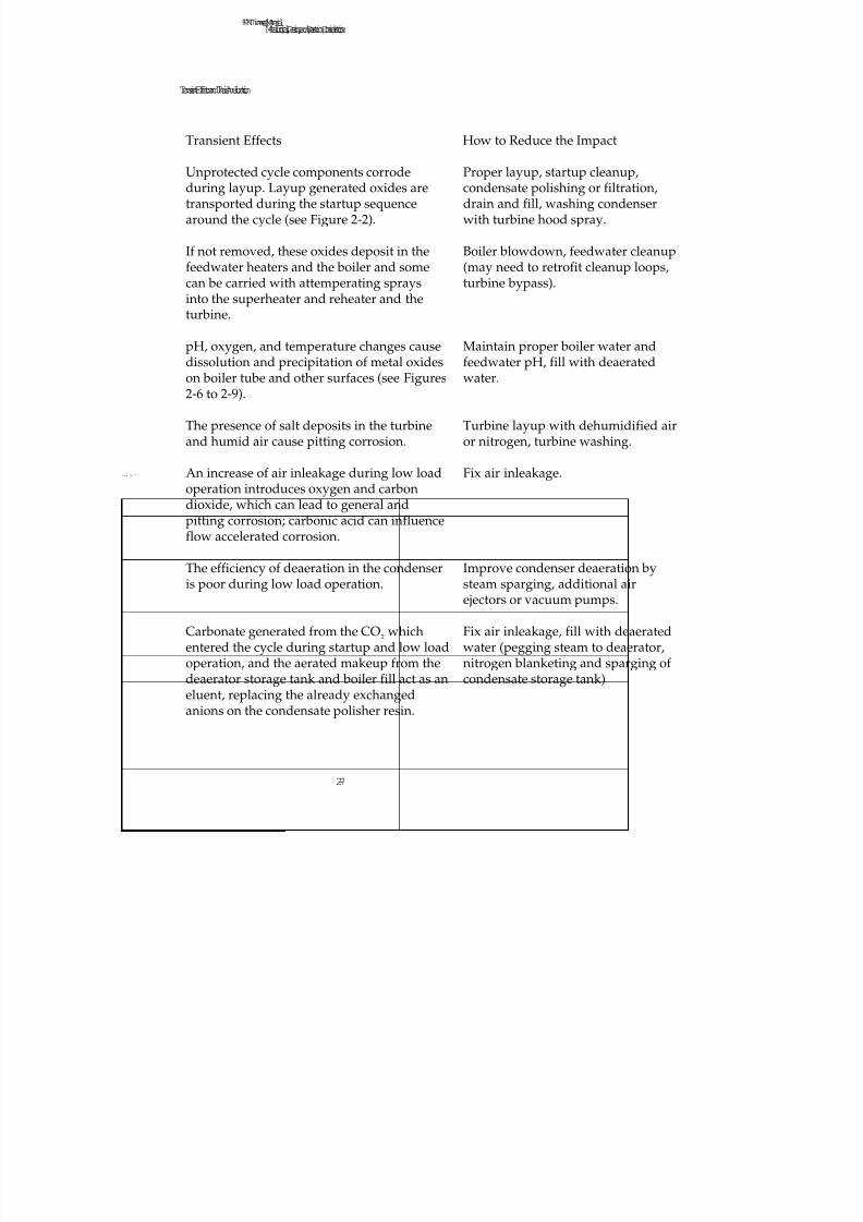
Table 2-1 Transient Effects and Their Amelioration.............................................................. 2-7
Table 2-2 Boiler Tube Damage Mechanisms Influenced by Cycle Chemistry (Adaptedfrom reference 27) (Discussion of each mechanism can be found in Reference 25) .... 2-18
Table 2-3 Turbine Deposits & Damage Mechanisms Influenced by Cycle Chemistry
(Adapted from reference 27) (Discussion of each mechanism can be found inReference 65) ............................................................................................................... 2-19
Table 2-4 Condensate/Feedwater Cycle Damage Mechanisms Influenced by StartupCycle Chemistry (Adapted from reference 27) .............................................................. 2-20
Table 2-5 Generation of Feedwater Corrosion Products by Corrosion and Flow-Accelerated Corrosion, and the Major Unit Transport and Deposition ProblemAreas for All-Ferrous Systems....................................................................................... 2-23
Table 2-6 Generation of Feedwater Corrosion Products by Corrosion and Flow-Accelerated Corrosion, and the Major Unit Transport and Deposition ProblemAreas for Mixed Metallurgy Systems ............................................................................. 2-25
Table 2-7 List of Concerns for Cycling Units (CH indicates the items affected by water
and steam chemistry) .................................................................................................... 2-28
Table 4-1 Shutdown and Layup Alternatives Showing Advantages and Disadvantagesfor Each Alternative......................................................................................................... 4-4

7/18/2019 EPRI Start Up, Lay Up & Shut Down Guidelines for Chemist
http://slidepdf.com/reader/full/epri-start-up-lay-up-shut-down-guidelines-for-chemist 22/256
7/18/2019 EPRI Start Up, Lay Up & Shut Down Guidelines for Chemist
http://slidepdf.com/reader/full/epri-start-up-lay-up-shut-down-guidelines-for-chemist 23/256
EPRI L icensed M aterial
1-1
1
INTRODUCTION
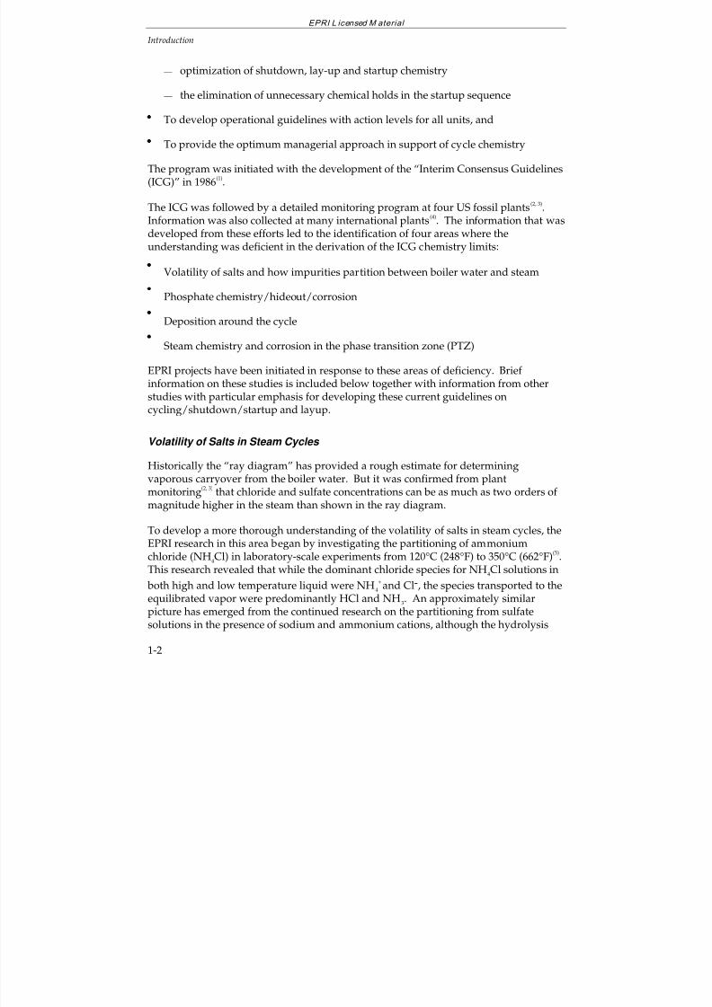
These guidelines cover water and steam chemistry control during transient operationincluding cycling and peaking, cold and warm startups, shutdown, and layup. Theydo not cover mechanical and thermal restraints imposed by equipment manufacturersand cycle design. However, these restraints, which often have the highest priority, areconsidered in the chemical guidelines and limits.
1.1 OVERVIEW OF THE EPRI FOSSIL PLANT CYCLE CHEMISTRYPROGRAM
The Electric Power Research Institute (EPRI) Fossil Plant Cycle Chemistry Program hasthe following goals:
To eliminate boiler tube failures related to cycle chemistry
To eliminate turbine chemical problems (low-pressure blade and disk cracks, andserious deposits throughout the turbine)
To develop optimized feedwater treatment:
— elimination of serious flow-accelerated corrosion (FAC)
— low iron and copper transport (<2 ppb at the economizer inlet)
To eliminate the need for boiler chemical cleaning
To provide simple, reliable cycle chemistry instrumentation and control:
— “core “ levels of instrumentation for all plants
— expert advisor
— direct on-line, in-situ instruments
To shorten the startup period by:
7/18/2019 EPRI Start Up, Lay Up & Shut Down Guidelines for Chemist
http://slidepdf.com/reader/full/epri-start-up-lay-up-shut-down-guidelines-for-chemist 24/256
EPRI L icensed M aterial
Introduction
1-2
— optimization of shutdown, lay-up and startup chemistry
— the elimination of unnecessary chemical holds in the startup sequence
To develop operational guidelines with action levels for all units, and
To provide the optimum managerial approach in support of cycle chemistry
The program was initiated with the development of the “Interim Consensus Guidelines(ICG)” in 1986
(1).
The ICG was followed by a detailed monitoring program at four US fossil plants(2, 3).Information was also collected at many international plants
(4). The information that was
developed from these efforts led to the identification of four areas where theunderstanding was deficient in the derivation of the ICG chemistry limits:
Volatility of salts and how impurities partition between boiler water and steam
Phosphate chemistry/hideout/corrosion
Deposition around the cycle
Steam chemistry and corrosion in the phase transition zone (PTZ)
EPRI projects have been initiated in response to these areas of deficiency. Brief information on these studies is included below together with information from otherstudies with particular emphasis for developing these current guidelines on
cycling/shutdown/startup and layup.
Volatility of Salts in Steam Cycles
Historically the “ray diagram” has provided a rough estimate for determiningvaporous carryover from the boiler water. But it was confirmed from plantmonitoring
(2, 3) that chloride and sulfate concentrations can be as much as two orders of
magnitude higher in the steam than shown in the ray diagram.
To develop a more thorough understanding of the volatility of salts in steam cycles, the
EPRI research in this area began by investigating the partitioning of ammoniumchloride (NH4Cl) in laboratory-scale experiments from 120°C (248°F) to 350°C (662°F)
(5).
This research revealed that while the dominant chloride species for NH4Cl solutions in
both high and low temperature liquid were NH4
+and Cl-, the species transported to the
equilibrated vapor were predominantly HCl and NH3. An approximately similarpicture has emerged from the continued research on the partitioning from sulfatesolutions in the presence of sodium and ammonium cations, although the hydrolysis
7/18/2019 EPRI Start Up, Lay Up & Shut Down Guidelines for Chemist
http://slidepdf.com/reader/full/epri-start-up-lay-up-shut-down-guidelines-for-chemist 25/256
EPRI L icensed M aterial
Introduction
1-3
reactions of sulfate ion complicate the speciation. The significant species in solution atlow temperature (condensate, blowdown) under AVT conditions are ammonium ions,ammonia, and hydroxide ions, with impurities of “sulfur” being present in the form of sulfate ions. At boiler operating conditions, equilibrium thermodynamics dictate thatammonia predominates over ammonium ion, whereas bisulfate and sulfate ions are at
much lower, but similar, concentrations. In the high temperature steam phase atequilibrium with this solution, again ammonia predominates over HCl. At lower, butcomparable, concentration levels are ammonium chloride, sodium hydroxide, sulfuricacid, sodium bisulfate and ammonium bisulfate, depending on the relative levels of these impurities in the boiler water. These preliminary calculations predict furtherrearrangement of the relative concentrations of the predominant molecules as the steamcools, with a much larger range in values. Clearly the situation is more complex withthe addition of more potentially-volatile species, particularly those which undergoadditional reactions in the liquid phase, and this complex chemistry goes far beyondthat which can be predicted from the ray diagram. The partitioning constants for
typical fossil plant salts, acids and bases are shown in Figure 1-1, where thepartitioning constant, KD, can be defined for a simple 1:1 electrolyte as the ratio of the
concentration of the neutral molecule in the vapor phase to the activities of thecomponent ions in the liquid phase.
7/18/2019 EPRI Start Up, Lay Up & Shut Down Guidelines for Chemist
http://slidepdf.com/reader/full/epri-start-up-lay-up-shut-down-guidelines-for-chemist 26/256
7/18/2019 EPRI Start Up, Lay Up & Shut Down Guidelines for Chemist
http://slidepdf.com/reader/full/epri-start-up-lay-up-shut-down-guidelines-for-chemist 27/256
EPRI L icensed M aterial
Introduction
1-5
very difficult. Also, an increasing number of utilities experienced serious internalcorrosion (attributed to acid phosphate corrosion) of the boiler waterwalls andsubsequent boiler tube failures when using this phosphate chemistry
(6, 7). The sodium
iron phosphate compound, maricite, has been found to be a magnetite-phosphatereaction product associated with cases of serious corrosion, and a distinguishing
difference from caustic gouging.
An EPRI project(8, 9)
was initiated to answer questions related to boiler tube corrosionand phosphate “hide-out” that have occurred in some boilers operating under CPT andto assist in modifying the ICG. This work generally extended the results of the 1964-68ASME Test Program
(10). The results are in general agreement with the literature
published on this subject. Specifically, no evidence of major corrosion attack was foundusing phosphate based boiler water treatment under conditions of:
Saturation pressure of 2800 psig (19.3 Mpa) and heat flux up to 200,000 BTU/hr ft2
(630kW/m2)
Departure from nucleate boiling (DNB) 1–2 hours in duration
Phosphate concentration to 10 ppm
Sodium to phosphate molar ratios ranging from 1.8–4.0
Magnetite deposition of 4 mg/cm2 (~4 grams/ft
2)
Low chloride and silica contamination
The results provide support for treatment methods which permit low levels (generally<1 ppm) of free caustic, such as equilibrium phosphate treatment under the tubecleanliness conditions tested.
Work conducted by the Canadian Electrical Association(11)
identified the sodium-ironphosphate reactions that take place up to 360°C. The major iron reaction products thatcause hideout (or more specifically in these experiments, “uptake by magnetite” at
Na/PO4 molar ratios near 2.5) were identified from batch experiments as NaFe++PO
4
(maricite) and Na4Fe+++(OH)(PO4)2 ·1/3NaOH. At higher Na/PO4 ratios Na3-2xFex
++
PO4 (a solid solution with Na3PO4) replaces maricite as the stable reaction product. At
360°C (680°F) “uptake by magnetite” behavior is similar except that there appears to beno significant amount of iron (+2) reaction products with Na/PO4 ratios of 2.5 orgreater. If the Na/PO4 ratio is large (>3.5), no “uptake by magnetite” takes place.
Nickel (NiO) reportedly behaves similarly. The Na/PO4 ratio in boiler water requiredto avoid the formation of more acidic phosphate mixtures (maricite + iron III phases)increases from about 2.3 at 315°C (599°F) to about 2.7 at 360°C (680°F). The injection of
7/18/2019 EPRI Start Up, Lay Up & Shut Down Guidelines for Chemist
http://slidepdf.com/reader/full/epri-start-up-lay-up-shut-down-guidelines-for-chemist 28/256
EPRI L icensed M aterial
Introduction
1-6
solutions with Na/PO4 ratios above 3.0 causes little or no iron-containing phosphatedeposit to form at 360°C (680°F).
EPRI published a revised Guideline(12)
for phosphate treatment for drum units whichtook into account the results of all these studies and relevant utility experiences. This
has been accomplished by providing two phosphate treatments (see Figure 5-2): thefirst, called phosphate treatment (PT), involves a broadening of the control range abovethe sodium-to-phosphate 2.8 molar ratio curve and allows operation with up to 1 ppmof free sodium hydroxide; the second, equilibrium phosphate treatment (EPT), operatesat or below phosphate levels which would lead to hideout. In high performance unitswith low tolerance for phosphate, operation with up to 1 ppm of free hydroxide isallowed. The major philosophy change incorporated has been to try to minimize oreliminate phosphate hideout and the continual correction of the boiler chemistry byaddition of the acid phosphate chemicals (di, and mono-sodium phosphate). PT isessentially an extension of EPT at higher phosphate levels. From a control viewpoint,the major difference is in the level of allowed contaminants, which must be consistentwith the buffering capacity of the treatment in use. Since the guideline was introducedin 1994, the incidence of corrosion has decreased markedly and utilities are able tocontrol the phosphate chemistry with minimum or reduced levels of hideout.Operation with these new phosphate treatments allows cycling of the unit withinchemical control boundaries.
Deposition and Chemical Cleaning
Deposition has a very important influence on waterside failure mechanisms andcomponent performance. The deposition of feedwater corrosion products, and
particularly their minimization, on the waterwalls of the boiler is key to a successful boiler treatment program. EPRI has recently initiated a strategic project to developquantitative understanding of deposition processes throughout the steam and watercycle. In the interim there are a number of published documents, which relate to theoperation of an optimum cycle chemistry program
(12–15), to the minimization of
deposition(16, 17) and to the determination of the need to chemically clean a boiler (18).
Steam, Chemistry and Corrosion in the Phase Transition Zone (PTZ)
Recently EPRI published a State-of-Knowledge document in this area(16)
which included
information on steam chemistry, moisture nucleation, early condensate and depositionwithin the phase transition area of the steam turbine. This work led to the formation of an international collaboration consisting of 23 organizations that are performingdetailed monitoring of these areas in operating turbines, and of extensive modelturbine studies of the PTZ. It is anticipated that the work will lead to a completeunderstanding of the environment in the PTZ, which will ultimately provide better
7/18/2019 EPRI Start Up, Lay Up & Shut Down Guidelines for Chemist
http://slidepdf.com/reader/full/epri-start-up-lay-up-shut-down-guidelines-for-chemist 29/256
EPRI L icensed M aterial
Introduction
1-7
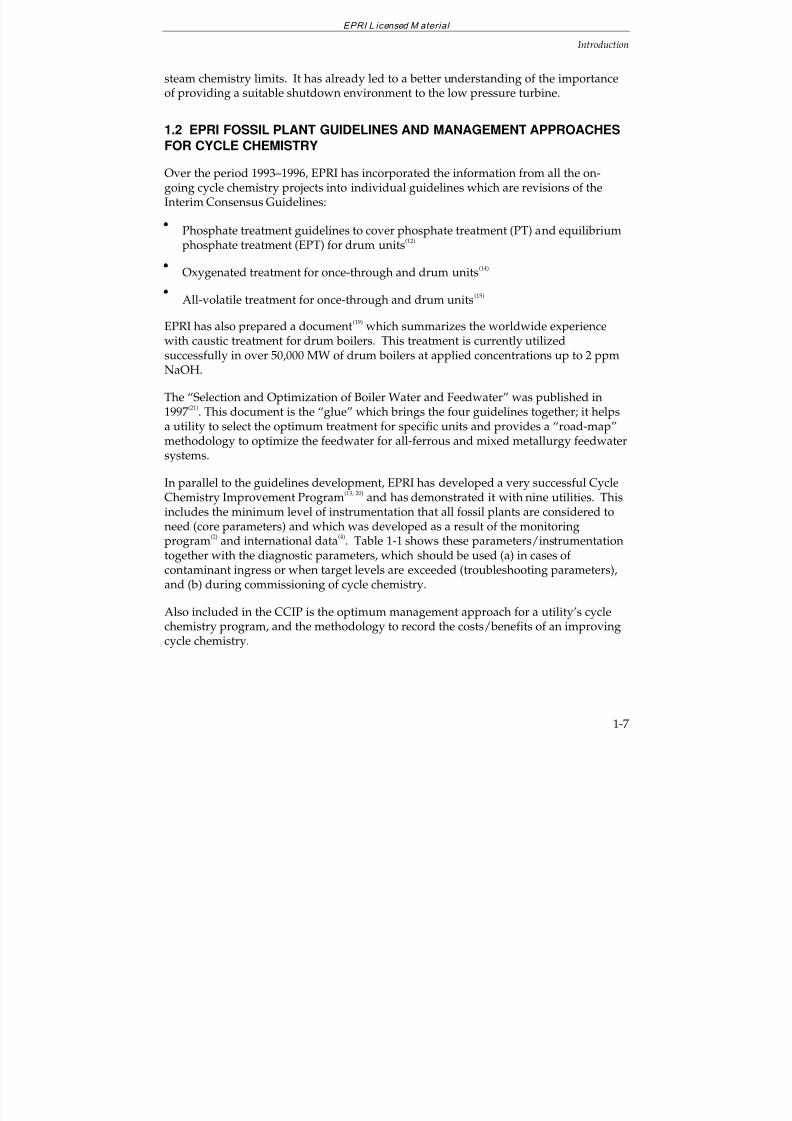
steam chemistry limits. It has already led to a better understanding of the importanceof providing a suitable shutdown environment to the low pressure turbine.
1.2 EPRI FOSSIL PLANT GUIDELINES AND MANAGEMENT APPROACHES
FOR CYCLE CHEMISTRY
Over the period 1993–1996, EPRI has incorporated the information from all the on-going cycle chemistry projects into individual guidelines which are revisions of theInterim Consensus Guidelines:
Phosphate treatment guidelines to cover phosphate treatment (PT) and equilibriumphosphate treatment (EPT) for drum units
(12)
Oxygenated treatment for once-through and drum units(14)
All-volatile treatment for once-through and drum units(15)
EPRI has also prepared a document(19)
which summarizes the worldwide experiencewith caustic treatment for drum boilers. This treatment is currently utilizedsuccessfully in over 50,000 MW of drum boilers at applied concentrations up to 2 ppmNaOH.
The “Selection and Optimization of Boiler Water and Feedwater” was published in1997
(21). This document is the “glue” which brings the four guidelines together; it helps
a utility to select the optimum treatment for specific units and provides a “road-map”methodology to optimize the feedwater for all-ferrous and mixed metallurgy feedwater
systems.
In parallel to the guidelines development, EPRI has developed a very successful CycleChemistry Improvement Program
(13, 20) and has demonstrated it with nine utilities. This
includes the minimum level of instrumentation that all fossil plants are considered toneed (core parameters) and which was developed as a result of the monitoringprogram
(2) and international data
(4). Table 1-1 shows these parameters/instrumentation
together with the diagnostic parameters, which should be used (a) in cases of contaminant ingress or when target levels are exceeded (troubleshooting parameters),and (b) during commissioning of cycle chemistry.
Also included in the CCIP is the optimum management approach for a utility’s cyclechemistry program, and the methodology to record the costs/benefits of an improvingcycle chemistry.
7/18/2019 EPRI Start Up, Lay Up & Shut Down Guidelines for Chemist
http://slidepdf.com/reader/full/epri-start-up-lay-up-shut-down-guidelines-for-chemist 30/256
EPRI L icensed M aterial
Introduction
1-8
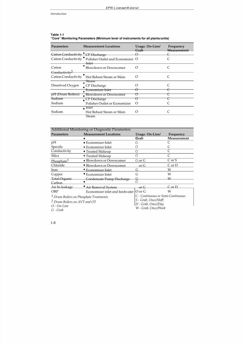
Table 1-1“Core” Monitoring Parameters (Minimum level of instruments for all plants/units)
Parameters Measurement Locations Usage. On-Line/ Grab
FrequencyMeasurement
Cation Conductivity
CP Discharge O C
Cation Conductivity
Polisher Outlet and Economizer Inlet
O C
Cation
Conductivity2
Blowdown or Downcomer O C
Cation Conductivity
Hot Reheat Steam or Main Steam
O C
Dissolved Oxygen
CP Discharge O C
Economizer Inlet O C
pH (Drum Boilers) Blowdown or Downcomer O CSodium
CP Discharge O C
Sodium
Polisher Outlet or Economizer Inlet
O C
Sodium
Hot Reheat Steam or Main Steam
O C
Additional Monitoring or Diagnostic Parameters
Parameters Measurement Locations Usage. On-Line/
Grab
Frequency
MeasurementpH
Economizer Inlet
C
SpecificConductivity
Economizer Inlet
Treated Makeup
CC
Silica
Treated Makeup
C
Phosphate1
Blowdown or Downcomer
or G C or S
Chloride
Blowdown or Downcomer
or G C or D
Iron
Economizer Inlet G W
Copper
Economizer Inlet G W
Total OrganicCarbon
Condensate Pump Discharge G W
Air In-leakage Air Removal System or G C or DORP
Economizer inlet and feedwater O or G W
1 Drum Boilers on Phosphate Treatments2 Drum Boilers on AVT and OT O - On-LineG - Grab
C - Continuous or Semi-ContinuousS - Grab, Once/ShiftD - Grab, Once/DayW - Grab, Once/Week
7/18/2019 EPRI Start Up, Lay Up & Shut Down Guidelines for Chemist
http://slidepdf.com/reader/full/epri-start-up-lay-up-shut-down-guidelines-for-chemist 31/256
EPRI L icensed M aterial
Introduction
1-9
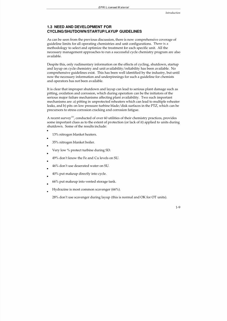
1.3 NEED AND DEVELOPMENT FOR
CYCLING/SHUTDOWN/STARTUP/LAYUP GUIDELINES
As can be seen from the previous discussion, there is now comprehensive coverage of
guideline limits for all operating chemistries and unit configurations. There is amethodology to select and optimize the treatment for each specific unit. All thenecessary management approaches to run a successful cycle chemistry program are alsoavailable.
Despite this, only rudimentary information on the effects of cycling, shutdown, startupand layup on cycle chemistry and unit availability/reliability has been available. Nocomprehensive guidelines exist. This has been well identified by the industry, but untilnow the necessary information and underpinnings for such a guideline for chemistsand operators has not been available.
It is clear that improper shutdown and layup can lead to serious plant damage such aspitting, oxidation and corrosion, which during operation can be the initiators of theserious major failure mechanisms affecting plant availability. Two such importantmechanisms are: a) pitting in unprotected reheaters which can lead to multiple reheaterleaks, and b) pits on low pressure turbine blade/disk surfaces in the PTZ, which can beprecursors to stress corrosion cracking and corrosion fatigue.
A recent survey(22)
, conducted of over 60 utilities of their chemistry practices, providessome important clues as to the extent of protection (or lack of it) applied to units duringshutdown. Some of the results include:
13% nitrogen blanket heaters.
35% nitrogen blanket boiler.
Very low % protect turbine during SD.
49% don’t know the Fe and Cu levels on SU.
46% don’t use deaerated water on SU.
40% put makeup directly into cycle.
66% put makeup into vented storage tank.
Hydrazine is most common scavenger (66%).
28% don’t use scavenger during layup (this is normal and OK for OT units).
7/18/2019 EPRI Start Up, Lay Up & Shut Down Guidelines for Chemist
http://slidepdf.com/reader/full/epri-start-up-lay-up-shut-down-guidelines-for-chemist 32/256
EPRI L icensed M aterial
Introduction
1-10
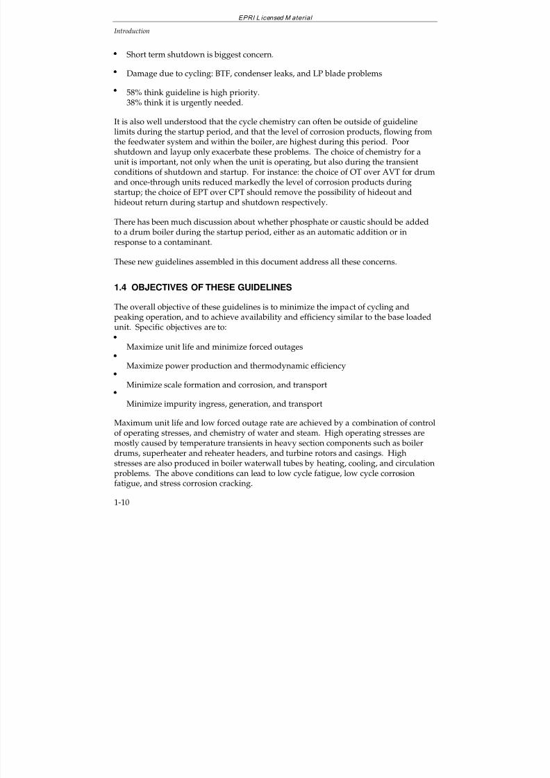
Short term shutdown is biggest concern.
Damage due to cycling: BTF, condenser leaks, and LP blade problems
58% think guideline is high priority.
38% think it is urgently needed.
It is also well understood that the cycle chemistry can often be outside of guidelinelimits during the startup period, and that the level of corrosion products, flowing fromthe feedwater system and within the boiler, are highest during this period. Poorshutdown and layup only exacerbate these problems. The choice of chemistry for aunit is important, not only when the unit is operating, but also during the transientconditions of shutdown and startup. For instance: the choice of OT over AVT for drumand once-through units reduced markedly the level of corrosion products duringstartup; the choice of EPT over CPT should remove the possibility of hideout andhideout return during startup and shutdown respectively.
There has been much discussion about whether phosphate or caustic should be addedto a drum boiler during the startup period, either as an automatic addition or inresponse to a contaminant.
These new guidelines assembled in this document address all these concerns.
1.4 OBJECTIVES OF THESE GUIDELINES
The overall objective of these guidelines is to minimize the impact of cycling and
peaking operation, and to achieve availability and efficiency similar to the base loadedunit. Specific objectives are to:
Maximize unit life and minimize forced outages
Maximize power production and thermodynamic efficiency
Minimize scale formation and corrosion, and transport
Minimize impurity ingress, generation, and transport
Maximum unit life and low forced outage rate are achieved by a combination of controlof operating stresses, and chemistry of water and steam. High operating stresses aremostly caused by temperature transients in heavy section components such as boilerdrums, superheater and reheater headers, and turbine rotors and casings. Highstresses are also produced in boiler waterwall tubes by heating, cooling, and circulationproblems. The above conditions can lead to low cycle fatigue, low cycle corrosionfatigue, and stress corrosion cracking.
7/18/2019 EPRI Start Up, Lay Up & Shut Down Guidelines for Chemist
http://slidepdf.com/reader/full/epri-start-up-lay-up-shut-down-guidelines-for-chemist 33/256
EPRI L icensed M aterial
Introduction
1-11
In marginally designed highly stressed components, such as for example LP turbine blade attachments, the stress cycling produced by frequent shutdowns can also reducecorrosion fatigue life.
Corrosion caused by ingress of cooling water impurities and oxygen and carbon
dioxide which enter through air inleakage, reduces the useful life of all waterside andsteamside component surfaces.
High power production and efficiency is achieved by minimization of impurity ingresswhich leads to generation and transport of iron and copper oxides. These oxides formscale in boiler and feedwater heater tubes, reducing heat transfer. In the turbine, metaloxides and salts form deposits which reduce the flow capacity and, through surfaceroughness, reduce thermodynamic efficiency.
1.5 SCOPE OF THESE GUIDELINES
These guidelines cover the following steam cycles, water treatments, types of operation,and pressure control:
Drum boiler units above 600 psi (4Mpa) drum pressure and once-throughsubcritical and supercritical boiler units
Units with and without condensate polishers
All-ferrous and mixed metallurgy feedwater systems
Superheaters, reheaters and turbines
Water treatments: Phosphate treatment and equilibrium phosphate treatment, all-volatile treatment, oxygenated treatment and caustic treatment
Base load, peaking, and cycling operation
Constant and sliding pressure
1.6 REFERENCES
1. Interim Consensus Guidelines on Fossil Plant Cycle Chemistry. Electric Power ResearchInstitute, Palo Alto, Calif. CS-4629. June 1986.
2. Monitoring Cycle Water Chemistry in Fossil Plants: Volume 1, Monitoring Results.Electric Power Research Institute, Palo Alto, Calif. EPRI GS-7556, Vol. October 1991.
7/18/2019 EPRI Start Up, Lay Up & Shut Down Guidelines for Chemist
http://slidepdf.com/reader/full/epri-start-up-lay-up-shut-down-guidelines-for-chemist 34/256
EPRI L icensed M aterial
Introduction
1-12
3. Monitoring Cycle Water Chemistry in Fossil Plants: Volume 3, Project Conclusions andRecommendations. Electric Power Research Institute, Palo Alto, Calif. EPRI GS-7556,Vol. 3, October 1991.
4. Monitoring Cycle Water Chemistry in Fossil Plants: Volume 2, International Water
Treatment Practices in Fossil Fuel Units. Electric Power Research Institute, Palo Alto,Calif. EPRI GS-7556, Vol. 2. December 1992.
5. Behavior of Ammonium Salts in Steam Cycles. Electric Power Research Institute, PaloAlto, Calif. EPRI TR-102377. Final Report. December 1993.
6. R.B. Dooley and S. Paterson, “Phosphate Treatment: Boiler Tube Failures Lead toOptimum Treatment”. Proceedings: 55th International Water Conference. EngineersSociety of Western Pennsylvania. 1994.
7. R.B. Dooley and W.P. McNaughton, Boiler Tube Failures: Theory and Practice. EPRI
Book TR-105261. 1996.
8. S.L. Goodstine and R.B. Dooley, “Behavior of Sodium Phosphates Under BoilerConditions”. Proceedings: 54th International Water Conference. Engineers Society of Western Pennsylvania. 1993.
9. Behavior of Sodium Phosphate Under Boiler Conditions. Electric Power ResearchInstitute, Palo Alto, Calif. TR-102431. June 1994.
10. P. Goldstein and C.L. Burton, “A Research Study on Internal Corrosion of HighPressure Boilers Final Report”. Transactions of the ASME, Journal of Engineering for
Power. April 1969.
11. P.R. Tremaine, L.G.S. Gray, B. Wiwchar, P. Taylor and J. Stodola, “PhosphateInteractions with Metal Oxides Under High Performance Boiler HideoutConditions”. Proceedings: 54th International Water Conference. Engineers Society of Western Pennsylvania. 1993.
12. Cycle Chemistry Guidelines for Fossil Plants: Phosphate Treatment for Drum Units.Electric Power Research Institute, Palo Alto, Calif. EPRI TR-103665. Final Report.December 1994.
13. Cycle Chemistry Corrosion and Deposition: Correction, Prevention and Control. ElectricPower Research Institute, Palo Alto, Calif. TR-103038. Final Report. December1993.
14. Cycle Chemistry Guidelines for Fossil Plants: Oxygenated Treatment. Electric PowerResearch Institute, Palo Alto, Calif. EPRI TR-102285. December 1994.
7/18/2019 EPRI Start Up, Lay Up & Shut Down Guidelines for Chemist
http://slidepdf.com/reader/full/epri-start-up-lay-up-shut-down-guidelines-for-chemist 35/256
EPRI L icensed M aterial
Introduction
1-13
15. Cycle Chemistry Guidelines for Fossil Plants: All-Volatile Treatment. Electric PowerResearch Institute, Palo Alto, Calif. EPRI TR-105041. April 1996.
16. Turbine Steam, Chemistry, and Corrosion. Electric Power Research Institute, Palo Alto,Calif. EPRI TR-103738. August 1994.
17. R.B. Dooley, J. Mathews, R. Pate and J. Taylor, “Optimum Chemistry for ‘All-Ferrous’ Feedwater Systems: Why Use an Oxygen Scavenger?”. Proceedings: 55thInternational Water Conference. Engineers Society of Western Pennsylvania. 1994.
18. Guidelines for Chemical Cleaning of Fossil-Fueled Steam Generating Equipment. ElectricPower Research Institute, Palo Alto, Calif. TR-102401. Final Report. June 1993.
19. Sodium Hydroxide for Conditioning the Boiler Water of Drum-Type Boilers. ElectricPower Research Institute, Palo Alto, Calif. TR-104007. January 1995.
20. Cycle Chemistry Improvement Program. Electric Power Research Institute, Palo Alto,Calif. TR-106371. April 1997.
21. Selection and Optimization of Boiler Water and Feedwater Treatments for Fossil Plants.Electric Power Research Institute, Palo Alto, Calif. TR-105040. March 1997.
22. Proceedings: Fifth International Conference on Fossil Plant Cycle Chemistry. Edited byR. B. Dooley and J. Mathews. Electric Power Research Institute, Palo Alto, Calif.TR-108459. November 1997.

7/18/2019 EPRI Start Up, Lay Up & Shut Down Guidelines for Chemist
http://slidepdf.com/reader/full/epri-start-up-lay-up-shut-down-guidelines-for-chemist 36/256
7/18/2019 EPRI Start Up, Lay Up & Shut Down Guidelines for Chemist
http://slidepdf.com/reader/full/epri-start-up-lay-up-shut-down-guidelines-for-chemist 37/256
EPRI L icensed M aterial
2-1
2
METALLURGICAL, DESIGN, AND OPERATING
CONSIDERATIONS
2.1 INTRODUCTION
In this Section, general and specific considerations relating water and steam chemistryand steam cycle design and operation to corrosion and deposit formation are discussed.Water chemistry, metallurgical, design, and operating aspects are combined becausethey all strongly interact, particularly in cycling units.
Operator and chemist actions influence the generation, cycle transport, and removal of corrosion products and ingress of impurities. Designers, operators, and chemistsinfluence the impurity concentration on heat transfer and turbine surfaces. Control of stresses and the number of stress cycles which interact with the chemistry in producingequipment damage (corrosion fatigue, stress corrosion, etc.) is by operation and design.
In Section 2.1 - Introduction, the impurity generation, transport, and corrosion effects,
and steam cycle materials are described. The basics of material corrosion and cyclecomponent mechanisms are given in Section 2.2, differences between the all-ferrous vs.copper-containing preboiler systems are outlined in Section 2.3, priorities for transientoperation in Section 2.4, and the effects of steam cycle component design and operationare discussed in Section 2.5. A brief assessment of the alternative water treatmentchemicals is presented in Section 2.6.
The steam cycle startup and cycling sequence may cover all or some of the followingmain steps:
shutdown
short or longterm layup
system draining and filling
water cleanup before firing
7/18/2019 EPRI Start Up, Lay Up & Shut Down Guidelines for Chemist
http://slidepdf.com/reader/full/epri-start-up-lay-up-shut-down-guidelines-for-chemist 38/256
EPRI L icensed M aterial
Metallurgical, Design, and Operating Considerations
2-2
boiler firing and warmup
steam turbine bypass operation
turbine roll and warmup
turbine speed ramp with holds
synchronization
load ramping
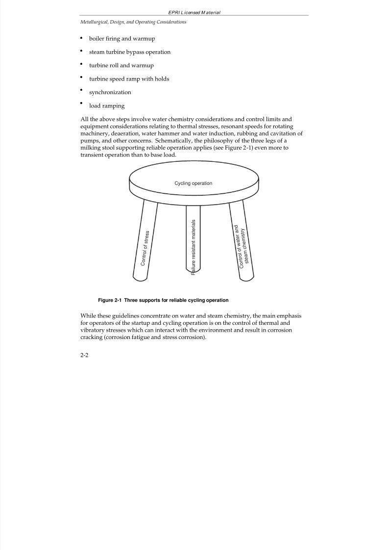
All the above steps involve water chemistry considerations and control limits andequipment considerations relating to thermal stresses, resonant speeds for rotatingmachinery, deaeration, water hammer and water induction, rubbing and cavitation of pumps, and other concerns. Schematically, the philosophy of the three legs of a
milking stool supporting reliable operation applies (see Figure 2-1) even more totransient operation than to base load.
Cycling operation
C o n
t r o l
o f
s t r e
s s
F a i l u r e r e s i s t a n t m a t e r i a l s
C o n t r o l o f w a t e r a n d
s t e a m c
h e m i s t r y
Figure 2-1 Three supports for reliable cycling operation
While these guidelines concentrate on water and steam chemistry, the main emphasisfor operators of the startup and cycling operation is on the control of thermal andvibratory stresses which can interact with the environment and result in corrosioncracking (corrosion fatigue and stress corrosion).
7/18/2019 EPRI Start Up, Lay Up & Shut Down Guidelines for Chemist
http://slidepdf.com/reader/full/epri-start-up-lay-up-shut-down-guidelines-for-chemist 39/256
EPRI L icensed M aterial
Metallurgical, Design, and Operating Considerations
2-3
Impurity Generation, Transport, and Corrosion Effects
To minimize impurity ingress, generation, and transport, the sources of impurities,effects of layup, and the startup, shutdown, and operational chemical transportcharacteristics of each cycle should be periodically determined during commissioning
and thereafter about every five years(1-6)
. Important characteristics which need to berecognized include:
oxidation of cycle materials and deposited copper during layup
precipitation of suspended solids in feedwater and boiler water due to changingpH, O2, redox potential, and temperature during layup and startup
introduction of aerated (O2 + CO2) makeup from storage tanks during system filland from the deaerator storage tank during startup
deaeration in the condenser and deaerator
boiler carryover and drum level control
transport of exfoliated oxides into the turbine and around the cycle
transport of metal oxides from dead legs and mud drums
sloughage of impurities from condensate polisher resins
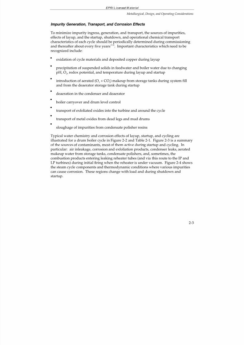
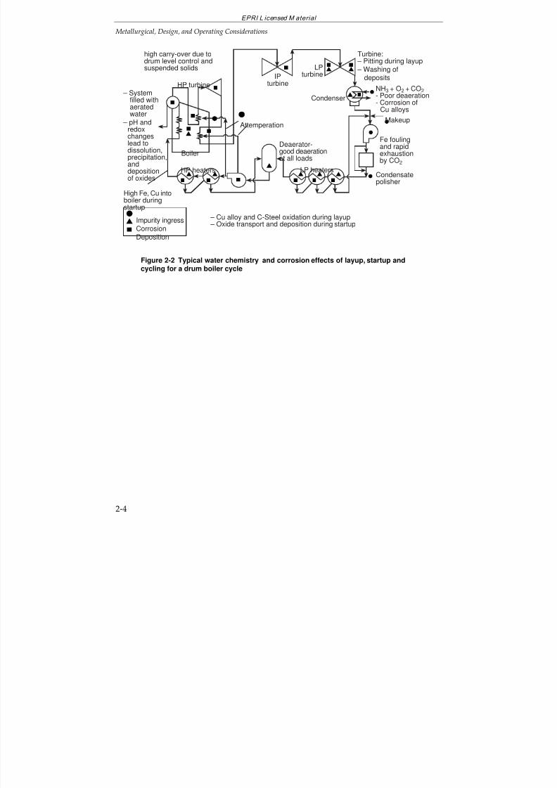
Typical water chemistry and corrosion effects of layup, startup, and cycling are
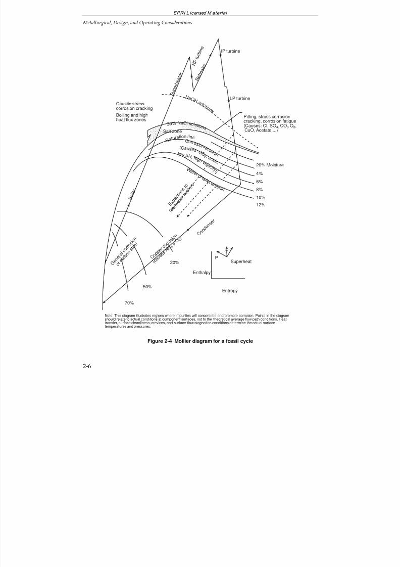
illustrated for a drum boiler cycle in Figure 2-2 and Table 2-1. Figure 2-3 is a summaryof the sources of contaminants, most of them active during startup and cycling. Inparticular: air inleakage, corrosion and exfoliation products, condenser leaks, aeratedmakeup water from storage tanks, condensate polishers, and, sometimes, thecombustion products entering leaking reheater tubes (and via this route to the IP andLP turbines) during initial firing when the reheater is under vacuum. Figure 2-4 showsthe steam cycle components and thermodynamic conditions where various impuritiescan cause corrosion. These regions change with load and during shutdown andstartup.
7/18/2019 EPRI Start Up, Lay Up & Shut Down Guidelines for Chemist
http://slidepdf.com/reader/full/epri-start-up-lay-up-shut-down-guidelines-for-chemist 40/256
EPRI L icensed M aterial
Metallurgical, Design, and Operating Considerations
2-4
Condensatepolisher
Deaerator-good deaerationat all loads
Fe foulingand rapidexhaustionby CO2
HP heaters
HP turbine – System
filled with
aeratedwater
– pH andredoxchangeslead todissolution,precipitation,anddepositionof oxides
LP heaters
NH3 + O2 + CO2- Poor deaeration- Corrosion of
Cu alloys
Attemperation
High Fe, Cu intoboiler duringstartup
– Cu alloy and C-Steel oxidation during layup – Oxide transport and deposition during startup
Impurity ingressCorrosion
Deposition
Turbine: – Pitting during layup – Washing of
deposits
high carry-over due todrum level control andsuspended solids
Boiler
Makeup
Condenser
IPturbine
LPturbine
Figure 2-2 Typical water chemistry and corrosion effects of layup, startup andcycling for a drum boiler cycle
7/18/2019 EPRI Start Up, Lay Up & Shut Down Guidelines for Chemist
http://slidepdf.com/reader/full/epri-start-up-lay-up-shut-down-guidelines-for-chemist 41/256
EPRI L icensed M aterial
Metallurgical, Design, and Operating Considerations
2-5
RegenerationDesignResin testing
monitoring/ operation
Resin testingMonitoringNitrogen sparging of storage tanks
Selection of chemicalsControl of cleaning
Material selectionAvoid copper
Water chemistryDesignExfoliationMaintenance
Design
Reheatermaintenance
QC: MaintenancePurchasing
Design, MaterialsPreventive maintenanceMonitoring
Selection of treatmentQC-Purchasing
Waterand
steam
*
*
* *
* **
*
*
C
o n d e n s e r l e a k s
P a i n t s , s o l v e n t s ,p r e s e r v a t i v e s , e t c .
C o m b
u s t i o n
p r o d u
c t s
A i r i n
l e a k
a g e C
o r r o
s i o n p r o d u c t s
C h e m i c a l c l e a n i n g
Ma k e u p wa t e r
C o n
d e n s
a t e p o l i s h e r s
W a t e r t r e a t m
e n t c h e m i c a l s
Figure 2-3 Sources of contaminants enhanced by cycling operation and examplesof engineering solutions.
7/18/2019 EPRI Start Up, Lay Up & Shut Down Guidelines for Chemist
http://slidepdf.com/reader/full/epri-start-up-lay-up-shut-down-guidelines-for-chemist 42/256
EPRI L icensed M aterial
Metallurgical, Design, and Operating Considerations
2-6
Caustic stresscorrosion cracking
Boiling and highheat flux zones
IP turbine
LP turbine S
u p e r h e a t e
r
R e h
e a t e
r
Salt zone
3 0 % NaCl s o l u t i o n s
S a t u ra
tion li n e C o r r o s i o n - e r o
s i o n l o w p H , h i g h v e l o c i t y )
(Cau s e s : C O 2 , a c i d s ,
W a t e r d r o p l e t e r o s i o n
C o p p
e r c o r r o
s i o n
( c a u
s e s N
H 4 + O 2 )
G e n
e r a l
c o r
r o s i o n
o f c a r b o
n s t e e l
70%
50%
20%
C o n d e n
s e r
Enthalpy
Entropy
Superheat
T
P
20% Moisture
4%
6%
8%
12%
10%
Pitting, stress corrosioncracking, corrosion fatigue(Causes: Cl, SO4, CO3 O2, CuO, Acetate,...)
N a O H s o l u t i o n s
B o i l e
r
H P
t u r b i n
e
E x t r a
c t i o
n s t o
f e e d w
a t e r
h e a t e
r s
Note: This diagram illustrates regions where impurities will concentrate and promote corrosion. Points in the diagramshould relate to actual conditions at component surfaces, not to the theoretical average flow path conditions. Heattransfer, surface cleanliness, crevices, and surface-flow stagnation conditions determine the actual surfacetemperatures and pressures.
Figure 2-4 Mollier diagram for a fossil cycle
7/18/2019 EPRI Start Up, Lay Up & Shut Down Guidelines for Chemist
http://slidepdf.com/reader/full/epri-start-up-lay-up-shut-down-guidelines-for-chemist 43/256
EPRI Licensed MaterialMetallurgical, Design, and Operating Considerations
2-7
TransientEffectsandTheirAmelioration
Transient Effects How to Reduce the Impact
Unprotected cycle components corrodeduring layup. Layup generated oxides aretransported during the startup sequencearound the cycle (see Figure 2-2).
Proper layup, startup cleanup,condensate polishing or filtration,drain and fill, washing condenserwith turbine hood spray.
If not removed, these oxides deposit in thefeedwater heaters and the boiler and somecan be carried with attemperating spraysinto the superheater and reheater and theturbine.
Boiler blowdown, feedwater cleanup(may need to retrofit cleanup loops,turbine bypass).
pH, oxygen, and temperature changes causedissolution and precipitation of metal oxideson boiler tube and other surfaces (see Figures2-6 to 2-9).
Maintain proper boiler water andfeedwater pH, fill with deaeratedwater.
The presence of salt deposits in the turbineand humid air cause pitting corrosion.
Turbine layup with dehumidified airor nitrogen, turbine washing.
An increase of air inleakage during low load
operation introduces oxygen and carbondioxide, which can lead to general andpitting corrosion; carbonic acid can influenceflow accelerated corrosion.
Fix air inleakage.
The efficiency of deaeration in the condenseris poor during low load operation.
Improve condenser deaeration bysteam sparging, additional airejectors or vacuum pumps.
Carbonate generated from the CO2 whichentered the cycle during startup and low load
operation, and the aerated makeup from thedeaerator storage tank and boiler fill act as aneluent, replacing the already exchangedanions on the condensate polisher resin.
Fix air inleakage, fill with deaeratedwater (pegging steam to deaerator,
nitrogen blanketing and sparging of condensate storage tank)
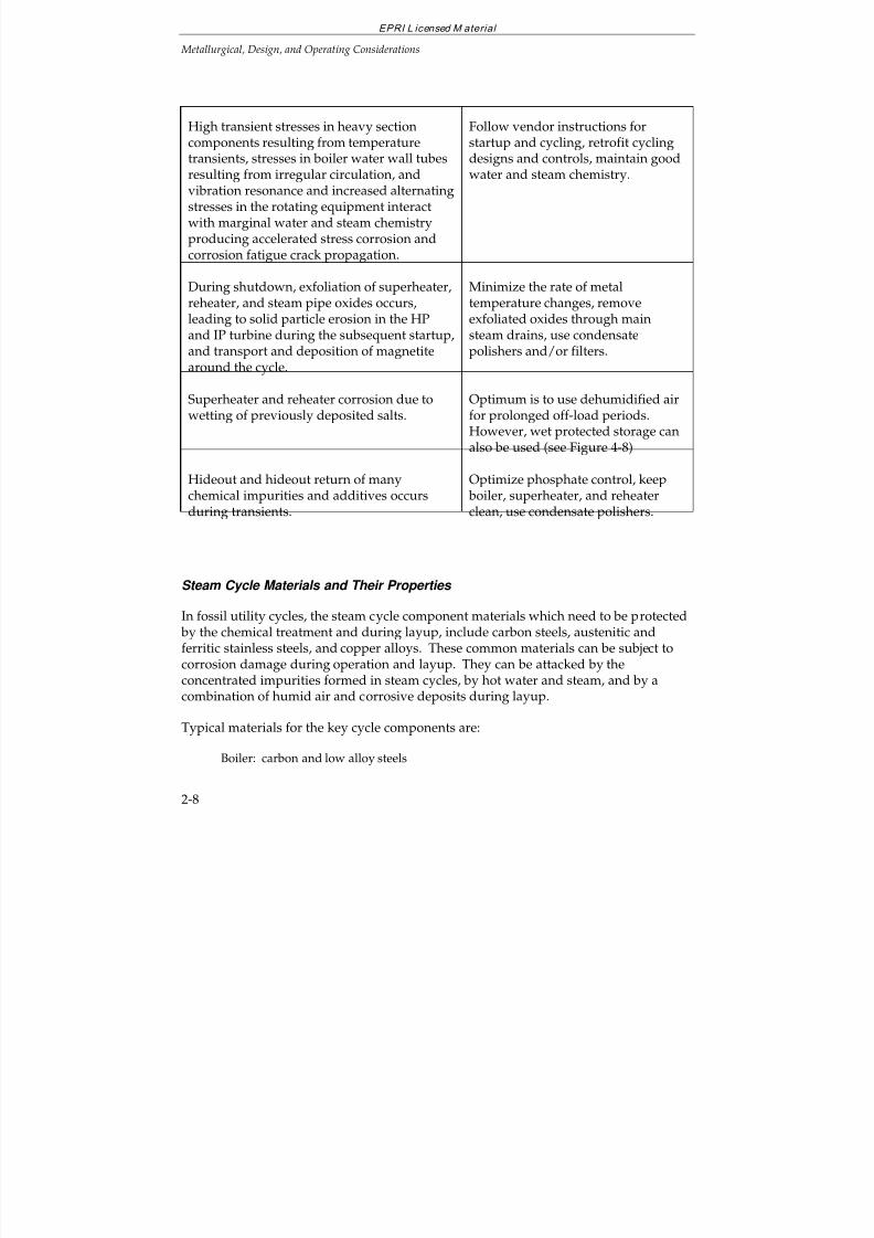
7/18/2019 EPRI Start Up, Lay Up & Shut Down Guidelines for Chemist
http://slidepdf.com/reader/full/epri-start-up-lay-up-shut-down-guidelines-for-chemist 44/256
EPRI L icensed M aterial
Metallurgical, Design, and Operating Considerations
2-8
High transient stresses in heavy sectioncomponents resulting from temperaturetransients, stresses in boiler water wall tubesresulting from irregular circulation, andvibration resonance and increased alternatingstresses in the rotating equipment interactwith marginal water and steam chemistryproducing accelerated stress corrosion andcorrosion fatigue crack propagation.
Follow vendor instructions forstartup and cycling, retrofit cyclingdesigns and controls, maintain goodwater and steam chemistry.
During shutdown, exfoliation of superheater,reheater, and steam pipe oxides occurs,leading to solid particle erosion in the HP
and IP turbine during the subsequent startup,and transport and deposition of magnetitearound the cycle.
Minimize the rate of metaltemperature changes, removeexfoliated oxides through main
steam drains, use condensatepolishers and/or filters.
Superheater and reheater corrosion due towetting of previously deposited salts.
Optimum is to use dehumidified airfor prolonged off-load periods.However, wet protected storage canalso be used (see Figure 4-8)
Hideout and hideout return of many
chemical impurities and additives occursduring transients.
Optimize phosphate control, keep
boiler, superheater, and reheaterclean, use condensate polishers.
Steam Cycle Materials and Their Properties
In fossil utility cycles, the steam cycle component materials which need to be protected by the chemical treatment and during layup, include carbon steels, austenitic andferritic stainless steels, and copper alloys. These common materials can be subject to
corrosion damage during operation and layup. They can be attacked by theconcentrated impurities formed in steam cycles, by hot water and steam, and by acombination of humid air and corrosive deposits during layup.
Typical materials for the key cycle components are:
Boiler: carbon and low alloy steels
7/18/2019 EPRI Start Up, Lay Up & Shut Down Guidelines for Chemist
http://slidepdf.com/reader/full/epri-start-up-lay-up-shut-down-guidelines-for-chemist 45/256
EPRI L icensed M aterial
Metallurgical, Design, and Operating Considerations
2-9
Superheater and reheater: carbon, low alloy and austenitic stainless steels
Steam piping: low alloy or carbon steel
Turbine: low alloy steels for rotors and HP and IP cylinders, ferritic stainless
steels and titanium alloys for blades, austenitic stainless steels for stationary blades, super alloys for high temperature bolting
Feedwater heaters and condensers: carbon steel for shells and feedwater heatertubing, austenitic and ferritic stainless steels, titanium, and copper alloys forfeedwater heater and condenser tubing
Feedwater piping: carbon steel, low alloy and stainless steels for sectionssusceptible to FAC
Material Properties
For the evaluation of the effects of cycling on steam cycle components, mechanical,fracture, fatigue, creep, and corrosion properties need to be known
(6-26). These
properties must cover behavior of smooth and notched surfaces, materials with andwithout defects, and crack propagation behavior under fatigue and corrosion crackingconditions.
New materials have been developed for replacement of the components, the life of which has been exhausted and for the retrofits for cycling service. These have betterfracture, fatigue, and creep properties.
2.2 STEAM CYCLE COMPONENT CORROSION AND DEPOSITS
During cycling and other transient operation, the corrosion situation in steam cycles isaggravated by increased steady and vibratory stresses (corrosion cracking) and often bymarginal water and steam chemistry, i.e., ingress of air, system filling with aeratedwater, transport of corrosion products, washing of deposited impurities, chemicalhideout, fast exhaustion of condensate polishers, condenser leaks (particularly duringstartups), etc.
Basics of Material Corrosion
The cycle materials can be subject to many corrosion mechanisms including:
general corrosion, and high temperature steam oxidation
galvanic corrosion
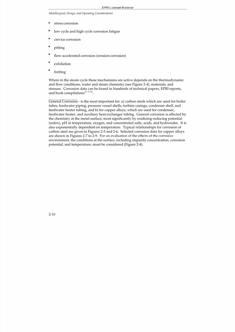
7/18/2019 EPRI Start Up, Lay Up & Shut Down Guidelines for Chemist
http://slidepdf.com/reader/full/epri-start-up-lay-up-shut-down-guidelines-for-chemist 46/256
EPRI L icensed M aterial
Metallurgical, Design, and Operating Considerations
2-10
stress corrosion
low cycle and high cycle corrosion fatigue
crevice corrosion
pitting
flow-accelerated corrosion (erosion-corrosion)
exfoliation
fretting
Where in the steam cycle these mechanisms are active depends on the thermodynamicand flow conditions, water and steam chemistry (see Figure 2-4), materials, and
stresses. Corrosion data can be found in hundreds of technical papers, EPRI reports,and book compilations(15, 23-26)
.
General Corrosion - is the most important for: a) carbon steels which are used for boilertubes, feedwater piping, pressure vessel shells, turbine casings, condenser shell, andfeedwater heater tubing, and b) for copper alloys, which are used for condenser,feedwater heater, and auxiliary heat exchanger tubing. General corrosion is affected bythe chemistry at the metal surface; most significantly by oxidizing-reducing potential(redox), pH at temperature, oxygen, and concentrated salts, acids, and hydroxides. It isalso exponentially dependent on temperature. Typical relationships for corrosion of carbon steel are given in Figures 2-5 and 2-6. Selected corrosion data for copper alloys
are shown in Figures 2-7 to 2-9. For an evaluation of the effects of the corrosiveenvironment, the conditions at the surface, including impurity concentration, corrosionpotential, and temperature, must be considered (Figure 2-4).
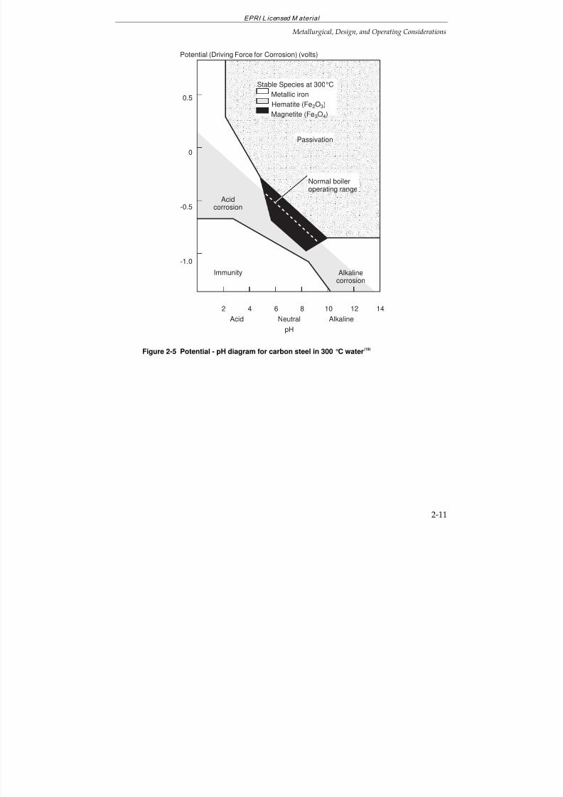
7/18/2019 EPRI Start Up, Lay Up & Shut Down Guidelines for Chemist
http://slidepdf.com/reader/full/epri-start-up-lay-up-shut-down-guidelines-for-chemist 47/256
EPRI L icensed M aterial
Metallurgical, Design, and Operating Considerations
2-11
0.5
0
-0.5
-1.0
Potential (Driving Force for Corrosion) (volts)
42 6 8 10
Acidcorrosion
Immunity
12 14
Passivation
Normal boileroperating range
Alkalinecorrosion
Stable Species at 300°C
Metallic iron
Hematite (Fe2O3)Magnetite (Fe3O4)
Acid Neutral Alkaline
pH
Figure 2-5 Potential - pH diagram for carbon steel in 300 °C water(19)
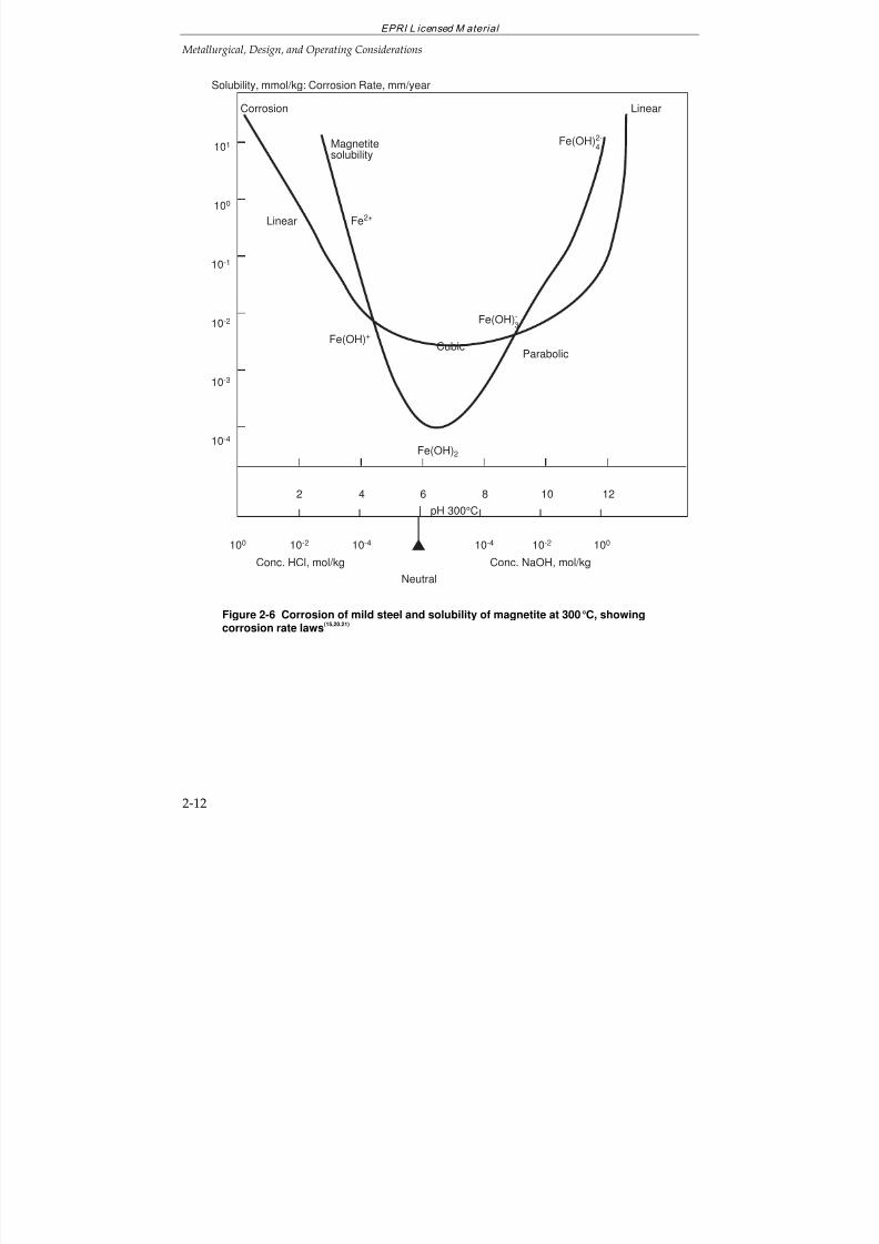
7/18/2019 EPRI Start Up, Lay Up & Shut Down Guidelines for Chemist
http://slidepdf.com/reader/full/epri-start-up-lay-up-shut-down-guidelines-for-chemist 48/256
EPRI L icensed M aterial
Metallurgical, Design, and Operating Considerations
2-12
Corrosion
101
100
10-1
10-2
10-3
10-4
Neutral
Solubility, mmol/kg: Corrosion Rate, mm/year
Conc. HCl, mol/kg Conc. NaOH, mol/kg
pH 300°C
Linear
2 4 6 8 10 12
100 10-2 10-4 10-4 10-2 100
Linear
Fe(OH)2
Fe(OH)2-4
Fe2+
CubicParabolic
Fe(OH)+
Fe(OH)-3
Magnetitesolubility
Figure 2-6 Corrosion of mild steel and solubility of magnetite at 300°C, showingcorrosion rate laws
(15,20.21)
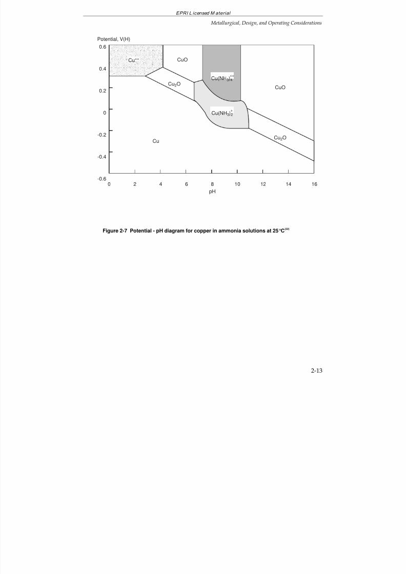
7/18/2019 EPRI Start Up, Lay Up & Shut Down Guidelines for Chemist
http://slidepdf.com/reader/full/epri-start-up-lay-up-shut-down-guidelines-for-chemist 49/256
EPRI L icensed M aterial
Metallurgical, Design, and Operating Considerations
2-13
0.6
0.4
0.2
0
-0.2
-0.4
-0.6
pH
2 4 6 8 10 16
CuO
CuO
Cu
Cu(NH3)4++
Cu(NH3)2+
Cu++
Cu2O
Cu2O
0 1412
Potential, V(H)
Figure 2-7 Potential - pH diagram for copper in ammonia solutions at 25°C
(22)
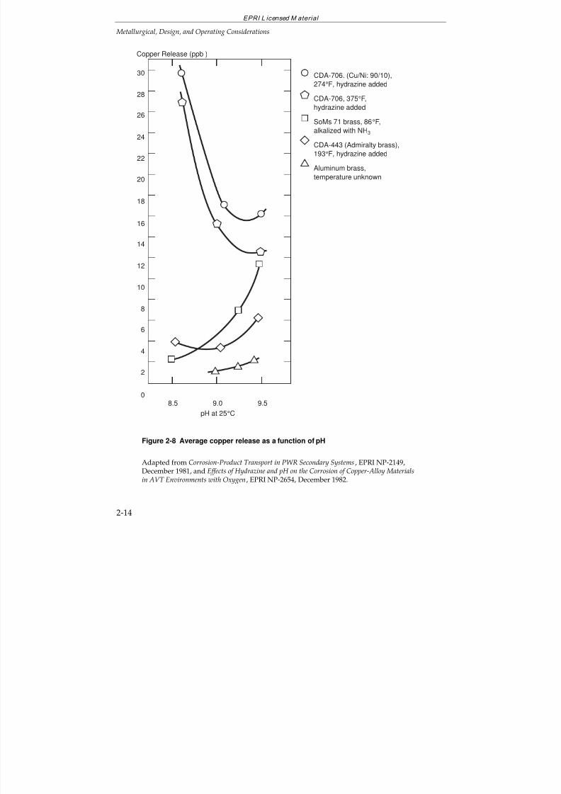
7/18/2019 EPRI Start Up, Lay Up & Shut Down Guidelines for Chemist
http://slidepdf.com/reader/full/epri-start-up-lay-up-shut-down-guidelines-for-chemist 50/256
EPRI L icensed M aterial
Metallurgical, Design, and Operating Considerations
2-14
8.5 9.0 9.5
pH at 25°C
8
6
0
4
2
Copper Release (ppb )
14
12
10
20
18
16
26
24
22
30
28
CDA-706. (Cu/Ni: 90/10),
274°F, hydrazine added
CDA-706, 375°F,
hydrazine added
SoMs 71 brass, 86°F,
alkalized with NH3
CDA-443 (Admiralty brass),
193°F, hydrazine added
Aluminum brass,
temperature unknown
Figure 2-8 Average copper release as a function of pH
Adapted from Corrosion-Product Transport in PWR Secondary Systems, EPRI NP-2149,December 1981, and Effects of Hydrazine and pH on the Corrosion of Copper-Alloy Materialsin AVT Environments with Oxygen, EPRI NP-2654, December 1982.
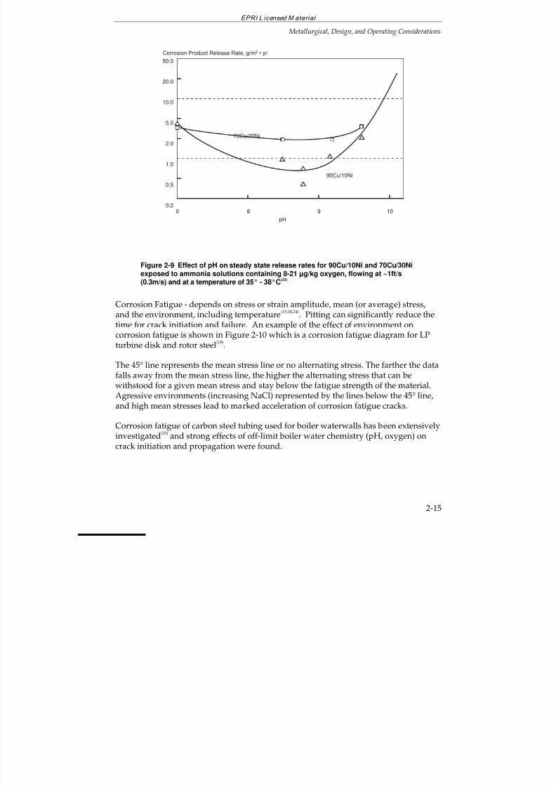
7/18/2019 EPRI Start Up, Lay Up & Shut Down Guidelines for Chemist
http://slidepdf.com/reader/full/epri-start-up-lay-up-shut-down-guidelines-for-chemist 51/256
EPRI L icensed M aterial
Metallurgical, Design, and Operating Considerations
2-15
50.0
20.0
10.0
5.0
2.0
1.0
0.5
0.2
pH98 10
70Cu/30Ni
0
Corrosion Product Release Rate, g/m2 • yr
90Cu/10Ni
Figure 2-9 Effect of pH on steady state release rates for 90Cu/10Ni and 70Cu/30Niexposed to ammonia solutions containing 8-21 µg/kg oxygen, flowing at ~1ft/s(0.3m/s) and at a temperature of 35° - 38°C
(22)
Corrosion Fatigue - depends on stress or strain amplitude, mean (or average) stress,
and the environment, including temperature
(15,18,24)
. Pitting can significantly reduce thetime for crack initiation and failure. An example of the effect of environment oncorrosion fatigue is shown in Figure 2-10 which is a corrosion fatigue diagram for LPturbine disk and rotor steel
(18).
The 45° line represents the mean stress line or no alternating stress. The farther the datafalls away from the mean stress line, the higher the alternating stress that can bewithstood for a given mean stress and stay below the fatigue strength of the material.Agressive environments (increasing NaCl) represented by the lines below the 45° line,and high mean stresses lead to marked acceleration of corrosion fatigue cracks.
Corrosion fatigue of carbon steel tubing used for boiler waterwalls has been extensivelyinvestigated
(25) and strong effects of off-limit boiler water chemistry (pH, oxygen) on
crack initiation and propagation were found.
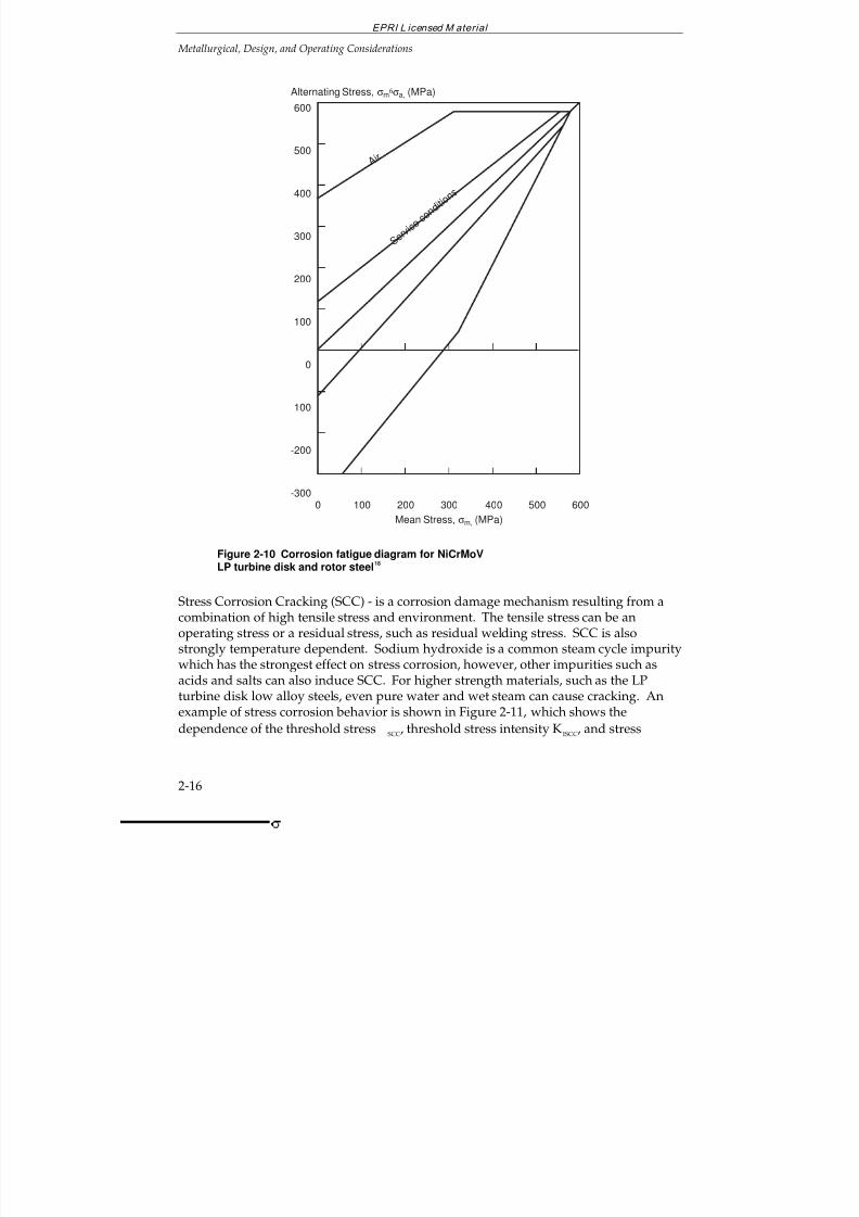
7/18/2019 EPRI Start Up, Lay Up & Shut Down Guidelines for Chemist
http://slidepdf.com/reader/full/epri-start-up-lay-up-shut-down-guidelines-for-chemist 52/256
EPRI L icensed M aterial
Metallurgical, Design, and Operating Considerations
2-16
600
500
400
300
200
100
0
100
-200
-300
Mean Stress, σm, (MPa)
0 100 200 300 400 600
A
i r
Alternating Stress, σm6σa, (MPa)
500
S e r v i c e
c o n d i t i o
n s
Figure 2-10 Corrosion fatigue diagram for NiCrMoVLP turbine disk and rotor steel
18
Stress Corrosion Cracking (SCC) - is a corrosion damage mechanism resulting from acombination of high tensile stress and environment. The tensile stress can be anoperating stress or a residual stress, such as residual welding stress. SCC is alsostrongly temperature dependent. Sodium hydroxide is a common steam cycle impuritywhich has the strongest effect on stress corrosion, however, other impurities such asacids and salts can also induce SCC. For higher strength materials, such as the LPturbine disk low alloy steels, even pure water and wet steam can cause cracking. Anexample of stress corrosion behavior is shown in Figure 2-11, which shows the
dependence of the threshold stress SCC, threshold stress intensity KISCC, and stress
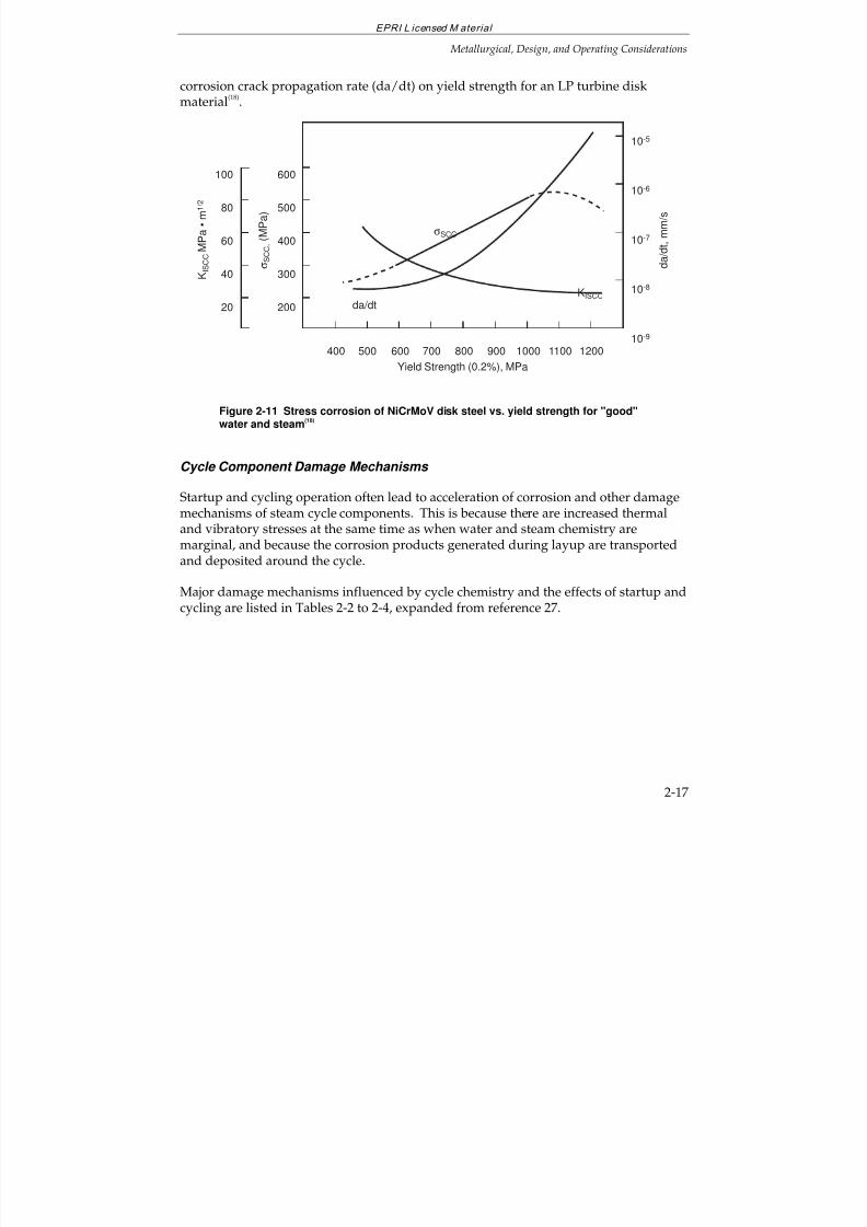
7/18/2019 EPRI Start Up, Lay Up & Shut Down Guidelines for Chemist
http://slidepdf.com/reader/full/epri-start-up-lay-up-shut-down-guidelines-for-chemist 53/256
EPRI L icensed M aterial
Metallurgical, Design, and Operating Considerations
2-17
corrosion crack propagation rate (da/dt) on yield strength for an LP turbine diskmaterial
(18).
600
500
400
300
200
Yield Strength (0.2%), MPa
400 500 600 700 800 1000
d a / d t , m m / s
900
σ S C C ,
( M P a )
K I S C C M P a • m 1 / 2
10-5
10-6
10-7
10-8
10-9
σSCC
da/dtKISCC
1100 1200
100
80
60
40
20
Figure 2-11 Stress corrosion of NiCrMoV disk steel vs. yield strength for "good"water and steam
(18)
Cycle Component Damage Mechanisms
Startup and cycling operation often lead to acceleration of corrosion and other damagemechanisms of steam cycle components. This is because there are increased thermaland vibratory stresses at the same time as when water and steam chemistry aremarginal, and because the corrosion products generated during layup are transportedand deposited around the cycle.
Major damage mechanisms influenced by cycle chemistry and the effects of startup andcycling are listed in Tables 2-2 to 2-4, expanded from reference 27.
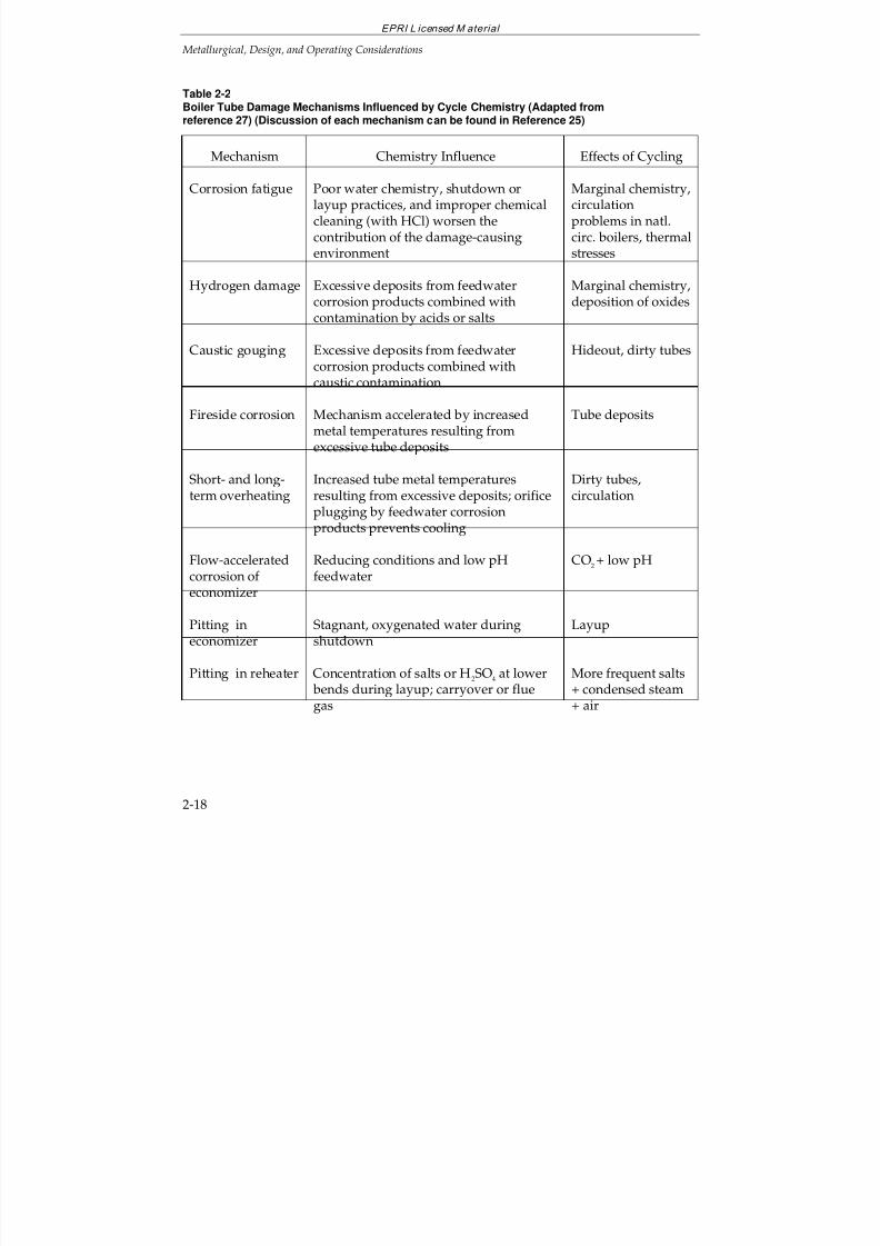
7/18/2019 EPRI Start Up, Lay Up & Shut Down Guidelines for Chemist
http://slidepdf.com/reader/full/epri-start-up-lay-up-shut-down-guidelines-for-chemist 54/256
EPRI L icensed M aterial
Metallurgical, Design, and Operating Considerations
2-18
Table 2-2Boiler Tube Damage Mechanisms Influenced by Cycle Chemistry (Adapted fromreference 27) (Discussion of each mechanism can be found in Reference 25)
Mechanism Chemistry Influence Effects of Cycling
Corrosion fatigue Poor water chemistry, shutdown orlayup practices, and improper chemicalcleaning (with HCl) worsen thecontribution of the damage-causingenvironment
Marginal chemistry,circulationproblems in natl.circ. boilers, thermalstresses
Hydrogen damage Excessive deposits from feedwatercorrosion products combined withcontamination by acids or salts
Marginal chemistry,deposition of oxides
Caustic gouging Excessive deposits from feedwatercorrosion products combined withcaustic contamination
Hideout, dirty tubes
Fireside corrosion Mechanism accelerated by increasedmetal temperatures resulting fromexcessive tube deposits
Tube deposits
Short- and long-term overheating
Increased tube metal temperaturesresulting from excessive deposits; orificeplugging by feedwater corrosionproducts prevents cooling
Dirty tubes,circulation
Flow-acceleratedcorrosion of economizer
Reducing conditions and low pHfeedwater
CO2+ low pH
Pitting ineconomizer
Stagnant, oxygenated water duringshutdown
Layup
Pitting in reheater Concentration of salts or H2SO4 at lower bends during layup; carryover or fluegas
More frequent salts+ condensed steam+ air
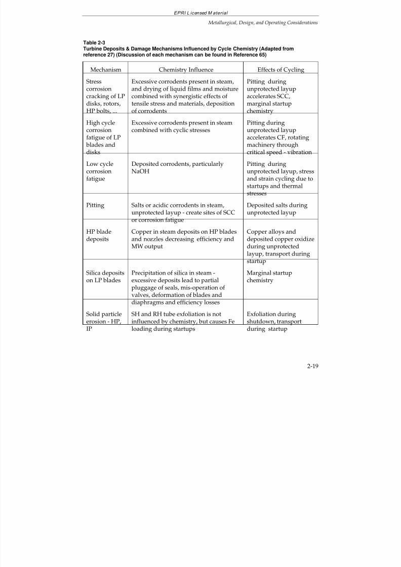
7/18/2019 EPRI Start Up, Lay Up & Shut Down Guidelines for Chemist
http://slidepdf.com/reader/full/epri-start-up-lay-up-shut-down-guidelines-for-chemist 55/256
EPRI L icensed M aterial
Metallurgical, Design, and Operating Considerations
2-19
Table 2-3Turbine Deposits & Damage Mechanisms Influenced by Cycle Chemistry (Adapted fromreference 27) (Discussion of each mechanism can be found in Reference 65)
Mechanism Chemistry Influence Effects of Cycling
Stresscorrosioncracking of LPdisks, rotors,HP bolts, ...
Excessive corrodents present in steam,and drying of liquid films and moisturecombined with synergistic effects of tensile stress and materials, depositionof corrodents
Pitting duringunprotected layupaccelerates SCC,marginal startupchemistry
High cyclecorrosionfatigue of LP blades and
disks
Excessive corrodents present in steamcombined with cyclic stresses
Pitting duringunprotected layupaccelerates CF, rotatingmachinery through
critical speed - vibration
Low cyclecorrosionfatigue
Deposited corrodents, particularlyNaOH
Pitting duringunprotected layup, stressand strain cycling due tostartups and thermalstresses
Pitting Salts or acidic corrodents in steam,unprotected layup - create sites of SCCor corrosion fatigue
Deposited salts duringunprotected layup
HP bladedeposits
Copper in steam deposits on HP bladesand nozzles decreasing efficiency andMW output
Copper alloys anddeposited copper oxidizeduring unprotectedlayup, transport duringstartup
Silica depositson LP blades
Precipitation of silica in steam -excessive deposits lead to partialpluggage of seals, mis-operation of valves, deformation of blades anddiaphragms and efficiency losses
Marginal startupchemistry
Solid particleerosion - HP,IP
SH and RH tube exfoliation is notinfluenced by chemistry, but causes Feloading during startups
Exfoliation duringshutdown, transportduring startup
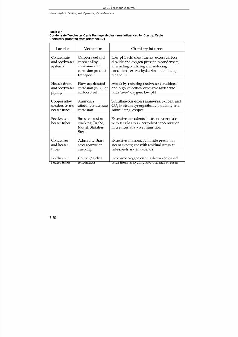
7/18/2019 EPRI Start Up, Lay Up & Shut Down Guidelines for Chemist
http://slidepdf.com/reader/full/epri-start-up-lay-up-shut-down-guidelines-for-chemist 56/256
EPRI L icensed M aterial
Metallurgical, Design, and Operating Considerations
2-20
Table 2-4Condensate/Feedwater Cycle Damage Mechanisms Influenced by Startup CycleChemistry (Adapted from reference 27)
Location Mechanism Chemistry Influence
Condensateand feedwatersystems
Carbon steel andcopper alloycorrosion andcorrosion producttransport
Low pH, acid constituents, excess carbondioxide and oxygen present in condensate;alternating oxidizing and reducingconditions, excess hydrazine solubilizingmagnetite
Heater drainand feedwater
piping
Flow-acceleratedcorrosion (FAC) of
carbon steel
Attack by reducing feedwater conditionsand high velocities, excessive hydrazine
with "zero" oxygen, low pH
Copper alloycondenser andheater tubes
Ammoniaattack/condensatecorrosion
Simultaneous excess ammonia, oxygen, andCO2 in steam synergistically oxidizing andsolubilizing copper
Feedwaterheater tubes
Stress corrosioncracking Cu/Ni,Monel, StainlessSteel
Excessive corrodents in steam synergisticwith tensile stress, corrodent concentrationin crevices, dry - wet transition
Condenserand heatertubes
Admiralty Brassstress corrosioncracking
Excessive ammonia/chloride present insteam synergistic with residual stress attubesheets and in u-bends
Feedwaterheater tubes
Copper/nickelexfoliation
Excessive oxygen on shutdown combinedwith thermal cycling and thermal stresses
7/18/2019 EPRI Start Up, Lay Up & Shut Down Guidelines for Chemist
http://slidepdf.com/reader/full/epri-start-up-lay-up-shut-down-guidelines-for-chemist 57/256
EPRI L icensed M aterial
Metallurgical, Design, and Operating Considerations
2-21
2.3 PREBOILER SYSTEMS - ALL FERROUS VS. MIXED METALLURGY
The concerns with the pre-boiler systems for cycling duty include:
reliability of components (see Table 2-4)
generation and transport of corrosion products(3-6,15,22)
deaeration (see Section 2.5)
The generation and transport of corrosion products (iron, copper, nickel, and zincoxides) can cause boiler waterwall tube scale accumulation which can lead to tubefailures and turbine deposits which can lead to MW and efficiency loss. Coppertransport and accumulation in the superheater can act as a continuing source of copperfor the turbine.
The high pressure drum boiler utility units with all-ferrous metallurgy (no copperalloys in feedwater heaters) usually have better efficiency and reliability than thesimilar units with mixed metallurgy. It has been concluded that copper alloys shouldnot be used for the heat exchanger tubing applications in steam cycles
(22). The main
water treatment dilemma is that there are different pH requirements for the control of general corrosion and flow-accelerated corrosion for carbon steel and copper alloys.Figure 2-12 shows that the feedwater pH for the best protection of carbon steel againstgeneral corrosion under deoxygenated reducing conditions should be above 9.4, but forthe protection of copper/zinc alloys, below 9.1.
Other than using an oxidizing cycle where the oxidizing-reducing potential, ORP >0mV the optimum protection of carbon steel against flow-accelerated corrosion (FAC) iswith pH>9.6 and oxygen concentration about 10 ppb. While to minimize coppercorrosion, excess hydrazine is required (ORP < 0mV), which may further accelerateFAC of carbon steel.
Auxiliary Heat Exchangers - such as the hydrogen cooler and gland steam condensershould be considered when deciding on feedwater control because they may containcopper alloys even while the feedwater system does not.
Layup - practices are very important for protection and corrosion product generationfor both ferrous and copper alloy materials (see Section 4).
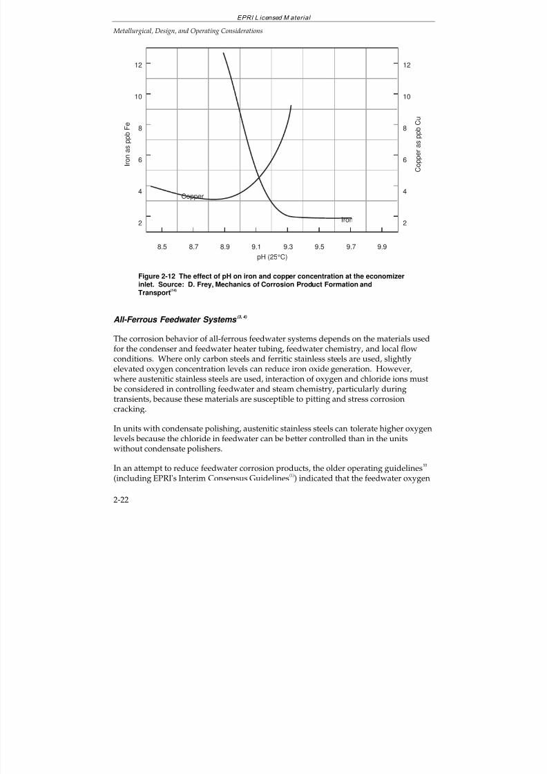
7/18/2019 EPRI Start Up, Lay Up & Shut Down Guidelines for Chemist
http://slidepdf.com/reader/full/epri-start-up-lay-up-shut-down-guidelines-for-chemist 58/256
EPRI L icensed M aterial
Metallurgical, Design, and Operating Considerations
2-22
12
10
8
6
4
2
C o p p e r a s p p b C u
I r o n a s p p b F e
Copper
Iron
pH (25°C)
8.5 8.7 8.9 9.1 9.3 9.79.5 9.9
12
10
8
6
4
2
Figure 2-12 The effect of pH on iron and copper concentration at the economizerinlet. Source: D. Frey, Mechanics of Corrosion Product Formation andTransport
(14)
All-Ferrous Feedwater Systems (3, 4)
The corrosion behavior of all-ferrous feedwater systems depends on the materials usedfor the condenser and feedwater heater tubing, feedwater chemistry, and local flowconditions. Where only carbon steels and ferritic stainless steels are used, slightlyelevated oxygen concentration levels can reduce iron oxide generation. However,where austenitic stainless steels are used, interaction of oxygen and chloride ions must be considered in controlling feedwater and steam chemistry, particularly duringtransients, because these materials are susceptible to pitting and stress corrosioncracking.
In units with condensate polishing, austenitic stainless steels can tolerate higher oxygenlevels because the chloride in feedwater can be better controlled than in the unitswithout condensate polishers.
In an attempt to reduce feedwater corrosion products, the older operating guidelines55
(including EPRI's Interim Consensus Guidelines(1)
) indicated that the feedwater oxygen
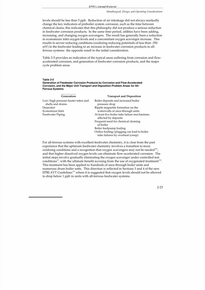
7/18/2019 EPRI Start Up, Lay Up & Shut Down Guidelines for Chemist
http://slidepdf.com/reader/full/epri-start-up-lay-up-shut-down-guidelines-for-chemist 59/256
EPRI L icensed M aterial
Metallurgical, Design, and Operating Considerations
2-23
levels should be less than 5 ppb. Reduction of air inleakage did not always markedlychange the key indicators of preboiler system corrosion, such as the time betweenchemical cleans; this indicates that this philosophy did not produce a serious reductionin feedwater corrosion products. In the same time period, utilities have been adding,increasing, and changing oxygen scavengers. The result has generally been a reduction
in economizer inlet oxygen levels and a concomitant oxygen scavenger increase. Thisresults in severe reducing conditions (oxidizing-reducing potentials of less than -350mV) in the feedwater leading to an increase in feedwater corrosion products in all-ferrous systems: the opposite result to the initial consideration.
Table 2-5 provides an indication of the typical areas suffering from corrosion and flow-accelerated corrosion, and generation of feedwater corrosion products, and the majorcycle problem areas.
Table 2-5Generation of Feedwater Corrosion Products by Corrosion and Flow-AcceleratedCorrosion, and the Major Unit Transport and Deposition Problem Areas for All-Ferrous Systems
Generation Transport and Deposition
Low/high pressure heater tubes and shells and drainsDeaeratorEconomizer InletFeedwater Piping
Boiler deposits and increased boiler pressure dropRipple magnetite formation on the waterwalls of once-through unitsAt least five boiler tube failure mechanisms
affected by depositsFrequent need for chemical cleaning of boilerBoiler feedpump foulingOrifice fouling/plugging can lead to boiler tube failures by overheat (creep)
For all-ferrous systems with excellent feedwater chemistry, it is clear from the pastexperience that the optimum feedwater chemistry involves a transition to moreoxidizing conditions and a recognition that oxygen scavengers may not be needed
(66),
and that higher dissolved oxygen levels can eliminate flow-accelerated corrosion. The
initial steps involve gradually eliminating the oxygen scavenger under controlled testconditions
(3), with the ultimate benefit accruing from the use of oxygenated treatment
(30).
This treatment has been applied to hundreds of once-through boiler units andnumerous drum boiler units. This direction is reflected in Sections 3 and 4 of the newEPRI AVT Guidelines
(31) where it is suggested that oxygen levels should not be allowed
to drop below 1 ppb in units with all-ferrous feedwater systems.
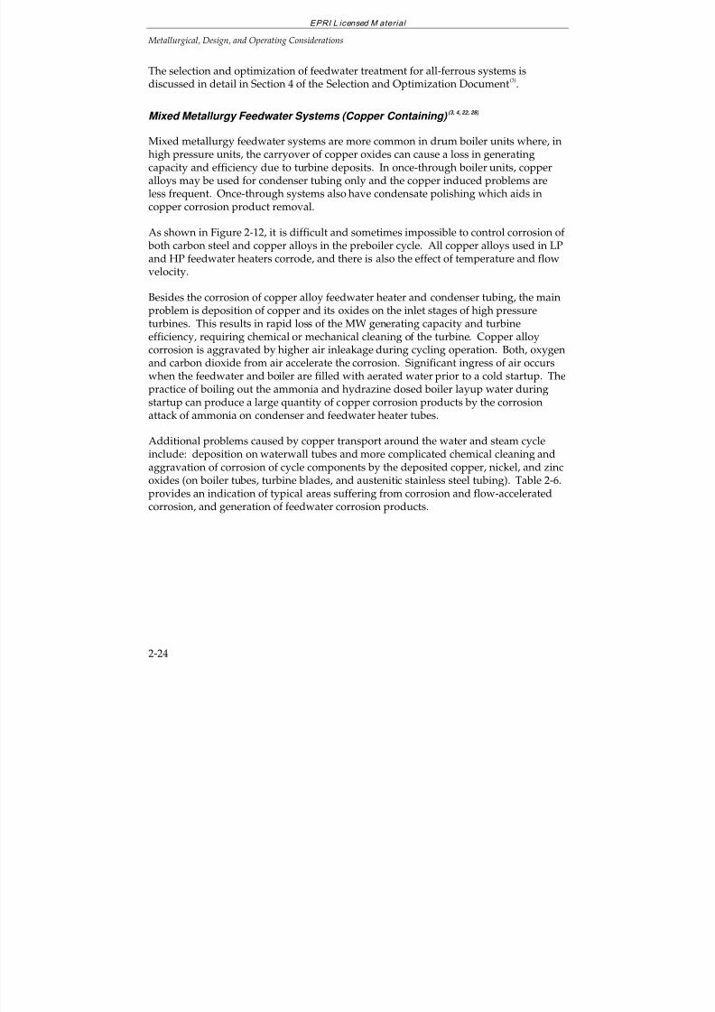
7/18/2019 EPRI Start Up, Lay Up & Shut Down Guidelines for Chemist
http://slidepdf.com/reader/full/epri-start-up-lay-up-shut-down-guidelines-for-chemist 60/256
EPRI L icensed M aterial
Metallurgical, Design, and Operating Considerations
2-24
The selection and optimization of feedwater treatment for all-ferrous systems isdiscussed in detail in Section 4 of the Selection and Optimization Document
(3).
Mixed Metallurgy Feedwater Systems (Copper Containing) (3, 4, 22, 28)
Mixed metallurgy feedwater systems are more common in drum boiler units where, inhigh pressure units, the carryover of copper oxides can cause a loss in generatingcapacity and efficiency due to turbine deposits. In once-through boiler units, copperalloys may be used for condenser tubing only and the copper induced problems areless frequent. Once-through systems also have condensate polishing which aids incopper corrosion product removal.
As shown in Figure 2-12, it is difficult and sometimes impossible to control corrosion of both carbon steel and copper alloys in the preboiler cycle. All copper alloys used in LPand HP feedwater heaters corrode, and there is also the effect of temperature and flow
velocity.
Besides the corrosion of copper alloy feedwater heater and condenser tubing, the mainproblem is deposition of copper and its oxides on the inlet stages of high pressureturbines. This results in rapid loss of the MW generating capacity and turbineefficiency, requiring chemical or mechanical cleaning of the turbine. Copper alloycorrosion is aggravated by higher air inleakage during cycling operation. Both, oxygenand carbon dioxide from air accelerate the corrosion. Significant ingress of air occurswhen the feedwater and boiler are filled with aerated water prior to a cold startup. Thepractice of boiling out the ammonia and hydrazine dosed boiler layup water duringstartup can produce a large quantity of copper corrosion products by the corrosionattack of ammonia on condenser and feedwater heater tubes.
Additional problems caused by copper transport around the water and steam cycleinclude: deposition on waterwall tubes and more complicated chemical cleaning andaggravation of corrosion of cycle components by the deposited copper, nickel, and zincoxides (on boiler tubes, turbine blades, and austenitic stainless steel tubing). Table 2-6.provides an indication of typical areas suffering from corrosion and flow-acceleratedcorrosion, and generation of feedwater corrosion products.
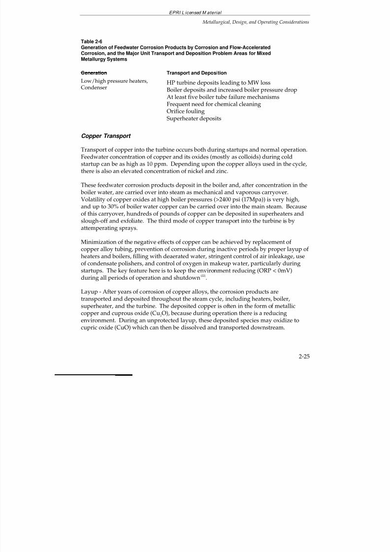
7/18/2019 EPRI Start Up, Lay Up & Shut Down Guidelines for Chemist
http://slidepdf.com/reader/full/epri-start-up-lay-up-shut-down-guidelines-for-chemist 61/256
EPRI L icensed M aterial
Metallurgical, Design, and Operating Considerations
2-25
Table 2-6Generation of Feedwater Corrosion Products by Corrosion and Flow-AcceleratedCorrosion, and the Major Unit Transport and Deposition Problem Areas for MixedMetallurgy Systems
Generation Transport and DepositionLow/high pressure heaters,Condenser
HP turbine deposits leading to MW lossBoiler deposits and increased boiler pressure dropAt least five boiler tube failure mechanismsFrequent need for chemical cleaningOrifice foulingSuperheater deposits
Copper Transport
Transport of copper into the turbine occurs both during startups and normal operation.Feedwater concentration of copper and its oxides (mostly as colloids) during coldstartup can be as high as 10 ppm. Depending upon the copper alloys used in the cycle,there is also an elevated concentration of nickel and zinc.
These feedwater corrosion products deposit in the boiler and, after concentration in the boiler water, are carried over into steam as mechanical and vaporous carryover.Volatility of copper oxides at high boiler pressures (>2400 psi (17Mpa)) is very high,and up to 30% of boiler water copper can be carried over into the main steam. Becauseof this carryover, hundreds of pounds of copper can be deposited in superheaters and
slough-off and exfoliate. The third mode of copper transport into the turbine is byattemperating sprays.
Minimization of the negative effects of copper can be achieved by replacement of copper alloy tubing, prevention of corrosion during inactive periods by proper layup of heaters and boilers, filling with deaerated water, stringent control of air inleakage, useof condensate polishers, and control of oxygen in makeup water, particularly duringstartups. The key feature here is to keep the environment reducing (ORP < 0mV)during all periods of operation and shutdown
(22).
Layup - After years of corrosion of copper alloys, the corrosion products are
transported and deposited throughout the steam cycle, including heaters, boiler,superheater, and the turbine. The deposited copper is often in the form of metalliccopper and cuprous oxide (Cu2O), because during operation there is a reducingenvironment. During an unprotected layup, these deposited species may oxidize tocupric oxide (CuO) which can then be dissolved and transported downstream.
7/18/2019 EPRI Start Up, Lay Up & Shut Down Guidelines for Chemist
http://slidepdf.com/reader/full/epri-start-up-lay-up-shut-down-guidelines-for-chemist 62/256
EPRI L icensed M aterial
Metallurgical, Design, and Operating Considerations
2-26
The selection and optimization of feedwater treatment for mixed metallurgy systems isdiscussed in detail in Section 4 of the Selection and Optimization Document
(3).
For mixed metallurgy systems, it is clear that reducing conditions (excess oxygenscavenger) are required for the non-ferrous materials
(22). The EPRI AVT Guidelines
(31)
suggest that oxygen levels should be kept below 5 ppb at the economizer inlet.However, the most appropriate oxygen scavenger concentration and residual oxygenlevel can only be determined by carrying out a series of tests. (See road map in Section4, Ref. 31 for mixed metallurgy feedwater systems.)
Because the copper alloy corrosion is caused by ammonia, oxygen, and ammoniumcarbonate and bicarbonate, other amines have been tried and also other oxygenscavengers besides hydrazine (because hydrazine decomposes into ammonia).However, these efforts were not successful in high pressure units, because the alternate(organic) chemicals decompose, forming organic acids and CO
2 which are also
corrosive.
2.4 PRIORITIES FOR TRANSIENT OPERATION
The operation and controls related to safety and mechanical damage of equipment havepriority over the water and steam chemistry control steps. However, it should berealized that some damage mechanisms, such as corrosion fatigue and stress corrosioncracking, are the result of an interaction of mechanical stresses with the environment.Also, there are high impact catastrophic failures such as LP turbine disc burst due tostress corrosion cracking, deaerator failures, and piping failures due to flow-acceleratedcorrosion which often occur during transients when a component, weakened by theslow corrosion damage (cracking or wall thinning), is overloaded beyond its fracturetoughness.
In failure prevention, the knowledge of the maximum loading conditions which oftenoccur during transients is as important as the knowledge of the corrosion damage. Thisis being achieved by inspections and by diagnostic monitoring of defects, pressures,stresses, and temperatures during all types of operation and by life predictinginstrumentation such as turbine rotor stress
(32), and boiler drum stress monitors
(33).
For the above reasons, the priorities are:
1. All safety-related operation, layup, and testing procedures such as safety valves,critical speeds, combustion, and water hammer.
2. Thermal and low cycle fatigue damage prevention such as control of drum, heater,and turbine rotor and piping stresses, and boiler circulation.
7/18/2019 EPRI Start Up, Lay Up & Shut Down Guidelines for Chemist
http://slidepdf.com/reader/full/epri-start-up-lay-up-shut-down-guidelines-for-chemist 63/256
EPRI L icensed M aterial
Metallurgical, Design, and Operating Considerations
2-27
3. Other operation-related problem prevention including control of boiler carryover,condenser vacuum, deaerator water hammer and water piston, deaerator storagetank water flashing and steam space collapse, pump cavitation (particularly for boiler feed pumps), feedwater heater non-condensable gas removal, water levelcontrols, drains, and superheater and reheater overheating.
4. Water and steam chemistry control including:
Control of ingress, generation, transport, and deposition of impurities
Control of all types of corrosion and erosion
Control of deposits in boiler, superheater, reheater, and turbine which can leadto corrosion, overheating, and loss of MW capacity and efficiency
Control of hideout of phosphate and other chemicals
Table 2-7 lists the items of concern that were identified in EPRI report EL-975(7)
. Thereport summarizes a survey of the cycling capabilities of the fossil-fired generatingunits in the US and Canada.
Additional concerns include increased risk of condenser leaks, increased ingress of aerated makeup, and high air inleakage during startups.
For the cycling units, in addition to the recommended physical changes to theconventional plant configuration, one fundamental solution to the problems of cyclingis to give closer attention to optimization of startup, shutdown and load changesequences. Such an optimization process can be performed most readily through theuse of effective analytical tools and control/monitoring instruments designedspecifically for this purpose.
The longterm reliability and availability of cycling units rely on the operator's attentionto, and recognition of, the impact of life expenditure due to thermal cycles and othertransient conditions on plant components. Since the effect on life expended of eachcycle is small, the overall effect may not be readily apparent to plant operators duringthe event and may not be recognized and properly considered in making the day-to-day operating decisions. Yet, the longterm cumulative effect of such cycles can result in
extended and expensive forced outages requiring major repairs or componentreplacement.
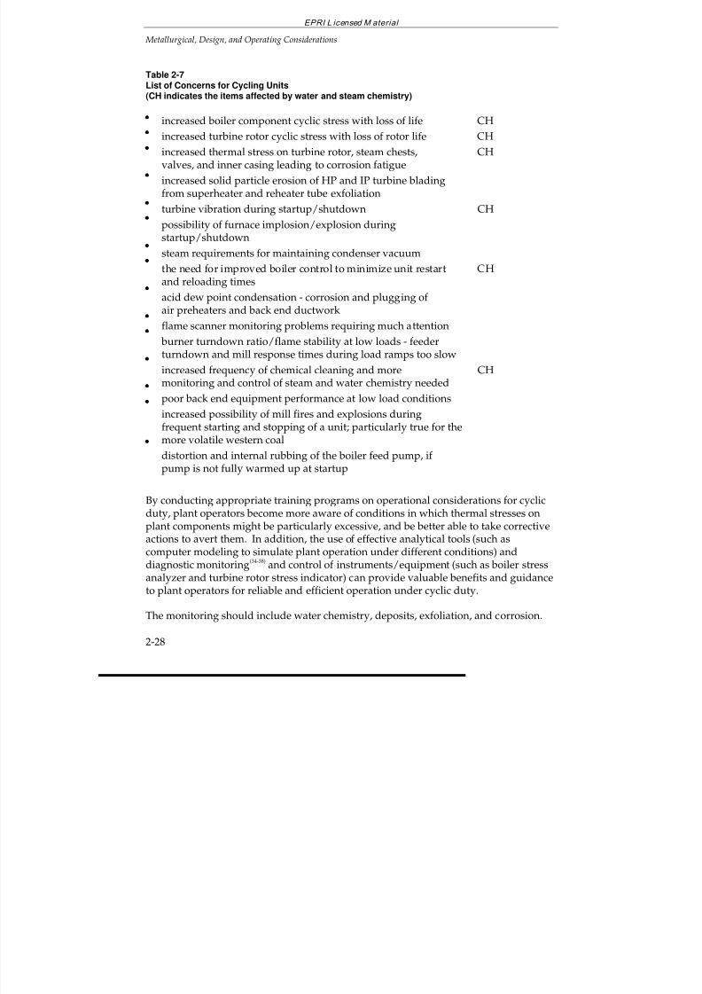
7/18/2019 EPRI Start Up, Lay Up & Shut Down Guidelines for Chemist
http://slidepdf.com/reader/full/epri-start-up-lay-up-shut-down-guidelines-for-chemist 64/256
EPRI L icensed M aterial
Metallurgical, Design, and Operating Considerations
2-28
Table 2-7List of Concerns for Cycling Units(CH indicates the items affected by water and steam chemistry)
increased boiler component cyclic stress with loss of life CH
increased turbine rotor cyclic stress with loss of rotor life CH
increased thermal stress on turbine rotor, steam chests, CHvalves, and inner casing leading to corrosion fatigue
increased solid particle erosion of HP and IP turbine bladingfrom superheater and reheater tube exfoliation
turbine vibration during startup/shutdown CH
possibility of furnace implosion/explosion duringstartup/shutdown
steam requirements for maintaining condenser vacuum
the need for improved boiler control to minimize unit restart CHand reloading times
acid dew point condensation - corrosion and plugging of air preheaters and back end ductwork
flame scanner monitoring problems requiring much attention
burner turndown ratio/flame stability at low loads - feederturndown and mill response times during load ramps too slow
increased frequency of chemical cleaning and more CHmonitoring and control of steam and water chemistry needed
poor back end equipment performance at low load conditions
increased possibility of mill fires and explosions duringfrequent starting and stopping of a unit; particularly true for themore volatile western coal
distortion and internal rubbing of the boiler feed pump, if pump is not fully warmed up at startup
By conducting appropriate training programs on operational considerations for cyclicduty, plant operators become more aware of conditions in which thermal stresses onplant components might be particularly excessive, and be better able to take corrective
actions to avert them. In addition, the use of effective analytical tools (such ascomputer modeling to simulate plant operation under different conditions) anddiagnostic monitoring
(34-38) and control of instruments/equipment (such as boiler stress
analyzer and turbine rotor stress indicator) can provide valuable benefits and guidanceto plant operators for reliable and efficient operation under cyclic duty.
The monitoring should include water chemistry, deposits, exfoliation, and corrosion.
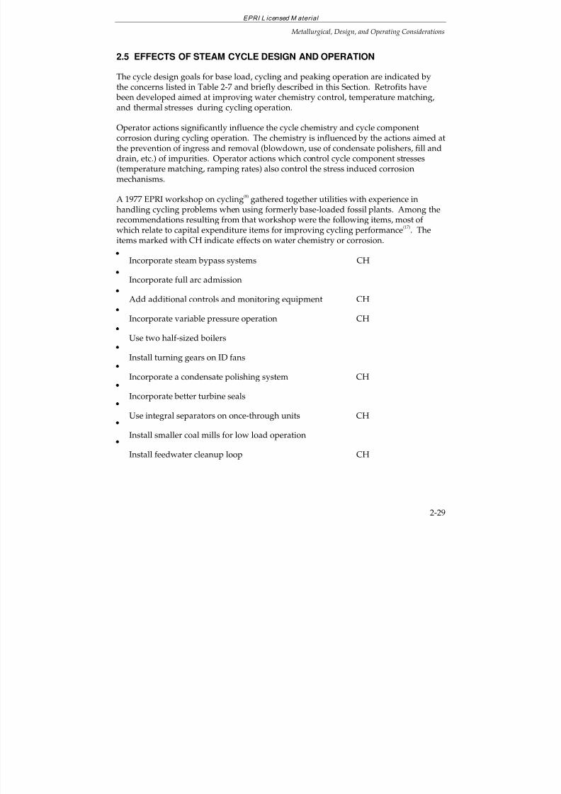
7/18/2019 EPRI Start Up, Lay Up & Shut Down Guidelines for Chemist
http://slidepdf.com/reader/full/epri-start-up-lay-up-shut-down-guidelines-for-chemist 65/256
EPRI L icensed M aterial
Metallurgical, Design, and Operating Considerations
2-29
2.5 EFFECTS OF STEAM CYCLE DESIGN AND OPERATION
The cycle design goals for base load, cycling and peaking operation are indicated bythe concerns listed in Table 2-7 and briefly described in this Section. Retrofits have been developed aimed at improving water chemistry control, temperature matching,
and thermal stresses during cycling operation.
Operator actions significantly influence the cycle chemistry and cycle componentcorrosion during cycling operation. The chemistry is influenced by the actions aimed atthe prevention of ingress and removal (blowdown, use of condensate polishers, fill anddrain, etc.) of impurities. Operator actions which control cycle component stresses(temperature matching, ramping rates) also control the stress induced corrosionmechanisms.
A 1977 EPRI workshop on cycling(8)
gathered together utilities with experience inhandling cycling problems when using formerly base-loaded fossil plants. Among therecommendations resulting from that workshop were the following items, most of which relate to capital expenditure items for improving cycling performance
(17). The
items marked with CH indicate effects on water chemistry or corrosion.
Incorporate steam bypass systems CH
Incorporate full arc admission
Add additional controls and monitoring equipment CH
Incorporate variable pressure operation CH
Use two half-sized boilers
Install turning gears on ID fans
Incorporate a condensate polishing system CH
Incorporate better turbine seals
Use integral separators on once-through units CH
Install smaller coal mills for low load operation
Install feedwater cleanup loop CH
7/18/2019 EPRI Start Up, Lay Up & Shut Down Guidelines for Chemist
http://slidepdf.com/reader/full/epri-start-up-lay-up-shut-down-guidelines-for-chemist 66/256
EPRI L icensed M aterial
Metallurgical, Design, and Operating Considerations
2-30
Drum Boiler vs. Once-through Boiler Units (7-12)
Generally, both types of units can be converted or originally designed for cyclingoperation. The most important part of such conversion is matching the steam andturbine metal temperatures. This is usually easier for drum boilers. In once-through
supercritical boilers, the transition through the critical region and from the evaporationmode to the once-through mode, and carryover of chemical impurities from the flashtank are of concern.
Sliding Pressure Operation (17,39-42)
Changing the turbine controls from partial arc admission to full arc admission andsliding pressure operation can reduce thermal stresses and improve efficiency andwater and steam chemistry control. The advantages of sliding pressure operation are:
1. Steam temperature distributions within the turbine are more uniform. Minimumvariation of first stage shell temperature.
2. Improved overall power plant efficiency - feed pump and other auxiliaries.
3. Reduced pressure results in lower heat transfer coefficient and correspondinglylower thermal stresses.
4. Reduced pressure - eases components' duty cycle.
5. Improved and extended control of primary and reheat steam temperature - due to
an increase in the latent heat of vaporization as pressure is decreased.
6. Improved water and steam chemistry control by reducing boiler carryover,improving boiler circulation in the natural circulation drum boilers, and possiblyreducing scale growth in waterwall tubes at lower pressures.
Boiler Concerns(15-17,25,39,40,43-46)
Boiler consideration for cycling operation cover the areas of stress generation,circulation in waterwall tubes, boiler water chemistry, and steam chemistry. The
problems are prevented by a combination of operator and chemist actions and boilerdesign.
The major factors affecting boiler design considerations for cyclic duty are:
number of cycles
heating and cooling rates
7/18/2019 EPRI Start Up, Lay Up & Shut Down Guidelines for Chemist
http://slidepdf.com/reader/full/epri-start-up-lay-up-shut-down-guidelines-for-chemist 67/256
EPRI L icensed M aterial
Metallurgical, Design, and Operating Considerations
2-31
component thickness, diameter and material
operating temperature level
waterwall tube circulation in drum boilers
Heavy thick-walled steam generator components (steam drums, superheater headertees, valves, etc.) should be watched closely for possible failure due to excessivethermal stress (with possible corrosion effects of water and steam chemistry). Startuprates of boilers containing such components have been limited by simple but effectiverules governing the rate of temperature change in these components. In the past, theselimitations did not substantially restrict unit availability because such units wereoperated in the base-load mode. With the conversion of such units to cycling duty,these simple but conservative startup limitations may no longer be adequate to protectagainst excessive loss-of-life.
Cyclic stresses resulting from such temperature changes must, therefore, bereconsidered in the boiler as well as the turbine. They result from either
temperature differences through the thickness of a containment; or
temperature differences between components attached to each other.
The steam drum and superheater outlet headers are the two thickest parts of a boilerand must be considered when thermally cycling the boiler.
There are two general areas in a boiler where parts with different temperaturecharacteristics are attached to each other. The first area covers superheater and reheatertube legs, which penetrate the enclosure and connect to an outlet header. These legsmust have sufficient flexibility to permit one end to move with the header at final steamtemperature, and the other end to move with the enclosure wall at saturationtemperature. The flexibility can be designed into a new boiler, but it may be limitingon an older one, particularly a wide one.
The second area is the attachment of nonpressure parts, such as windboxes andvestibules, to tube walls that are at saturation temperature. These parts respond to airor flue-gas temperature rather than saturation temperature, and change temperature
more slowly.
EPRI developed a boiler thermal stress and condition analyzer to evaluate the conditionof boiler components during episodes of high temperature and pressures or highthermal stresses
(33). This analyzer operates on-line to accumulate a history of damaging
incidents.
7/18/2019 EPRI Start Up, Lay Up & Shut Down Guidelines for Chemist
http://slidepdf.com/reader/full/epri-start-up-lay-up-shut-down-guidelines-for-chemist 68/256
EPRI L icensed M aterial
Metallurgical, Design, and Operating Considerations
2-32
In one EPRI study of a cycling boiler (CS-2438)(44)
, it was found that on/off daily loadcycling of the boiler requires design changes before this type of operation is performedon a regular basis. Even with design changes, the thermal shock of the boiler thatoccurs with operation of once-through boilers when "cold" water enters a "hot" boilermay eventually lead to failure of boiler components. Recommended design changes
included:
Change boiler furnace to spiral design.
Change bypass system, use full pressure separator design, or full pressure separatorrecirculation pump design.
Make provision for quick water cleanup and provide for feedwater heating beforefiring boiler.
Add flame monitoring system.
Provide new burners and burner control system.
Upgrade unit control system.
Add new and larger computer to better monitor temperatures in boiler and turbine.
Boiler Carryover - in drum boilers is sensitive to the drum level which could beelevated along the whole drum length or locally during shutdowns, startups, and rapidload or boiler pressure changes. Operating events such as the use of circulating pumps,coal mills and burners, and soot blowing can significantly influence the drum level. It
is imperative to experimentally determine the carryover for all modes of operation andafter equipment changes are made, particularly after installation of new burners whichmay change the boiler heat flux patterns.
The water chemistry parameters which can increase boiler carryover during cyclingoperation and startups include: high dissolved and suspended solids and highhydroxide alkalinity, particularly when combined with organic matter.
Exfoliation - of oxides (mostly magnetite) from superheater, reheater, and steam pipingcan be accelerated by more frequent shutdowns. The exfoliation occurs during
shutdown because the ID of the tubes and piping cools faster than the metal, and because of the difference in the coefficient of thermal expansion between the oxides andthe steel
(47). The exfoliated oxides collect in the lower bends of the SH and RH pendant
platens and, during the following startup, are carried into the turbine causing solidparticle erosion
(48). These oxides also increase the iron and copper concentration in
condensate and feedwater and cause overloading of condensate polishers. The oxidesextracted through turbine extractions go through feedwater heaters and heater drains
7/18/2019 EPRI Start Up, Lay Up & Shut Down Guidelines for Chemist
http://slidepdf.com/reader/full/epri-start-up-lay-up-shut-down-guidelines-for-chemist 69/256
EPRI L icensed M aterial
Metallurgical, Design, and Operating Considerations
2-33
into the suction of the boiler feed pump and then back into the boiler, and thus bypassthe condensate polishers.
Mud Drums - or lower headers often collect large quantities of oxides (up to hundredsof pounds) in the form of sludge. The quantity of sludge can be reduced markedly by
blowing down the lower boiler drains just prior to shutdown at 50 to 70 psi (0.3-0.5MPa), by drain and fill, by manual cleaning during shutdown, and by blowing thelower drains during the early startup. During startups, circulation from the muddrums through the economizer into the boiler transports large quantities of iron andcopper
(28).
Turbine(18,42,49,50)
Cycling and peaking operation can affect the turbine by generation of corrosivedeposits which reduce generating capacity and efficiency, by producing high thermal
and vibratory stresses, by introduction of exfoliated oxides from the superheater andreheater (leading to solid particle erosion), and by introducing humid air which can,together with corrosive deposits, lead to pitting during layup. A positive effect of cycling can be washing of the accumulated deposits during startup.
Some of the possible turbine modifications that have been considered for cycling dutyinclude:
layup dehumidification or nitrogen blanketing to reduce corrosion
change from constant to sliding pressure(40-42)
change from partial arc to full arc admission(49)
turbine by-pass(49-50)
design changes to decrease thermal strains (decreasing notch effects, better heatingand cooling)
(50)
materials with higher ductility
changing water glands to steam glands
bearing and turning gear modifications
instrumentation and control
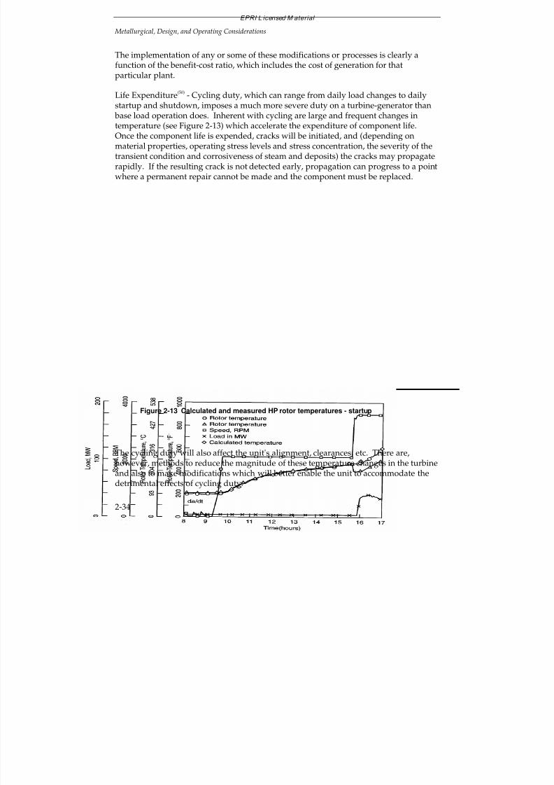
7/18/2019 EPRI Start Up, Lay Up & Shut Down Guidelines for Chemist
http://slidepdf.com/reader/full/epri-start-up-lay-up-shut-down-guidelines-for-chemist 70/256
EPRI L icensed M aterial
Metallurgical, Design, and Operating Considerations
2-34
The implementation of any or some of these modifications or processes is clearly afunction of the benefit-cost ratio, which includes the cost of generation for thatparticular plant.
Life Expenditure(50)
- Cycling duty, which can range from daily load changes to daily
startup and shutdown, imposes a much more severe duty on a turbine-generator than base load operation does. Inherent with cycling are large and frequent changes intemperature (see Figure 2-13) which accelerate the expenditure of component life.Once the component life is expended, cracks will be initiated, and (depending onmaterial properties, operating stress levels and stress concentration, the severity of thetransient condition and corrosiveness of steam and deposits) the cracks may propagaterapidly. If the resulting crack is not detected early, propagation can progress to a pointwhere a permanent repair cannot be made and the component must be replaced.
Figure 2-13 Calculated and measured HP rotor temperatures - startup
The cycling duty will also affect the unit's alignment, clearances, etc. There are,however, methods to reduce the magnitude of these temperature changes in the turbineand also to make modifications which will better enable the unit to accommodate thedetrimental effects of cycling duty.
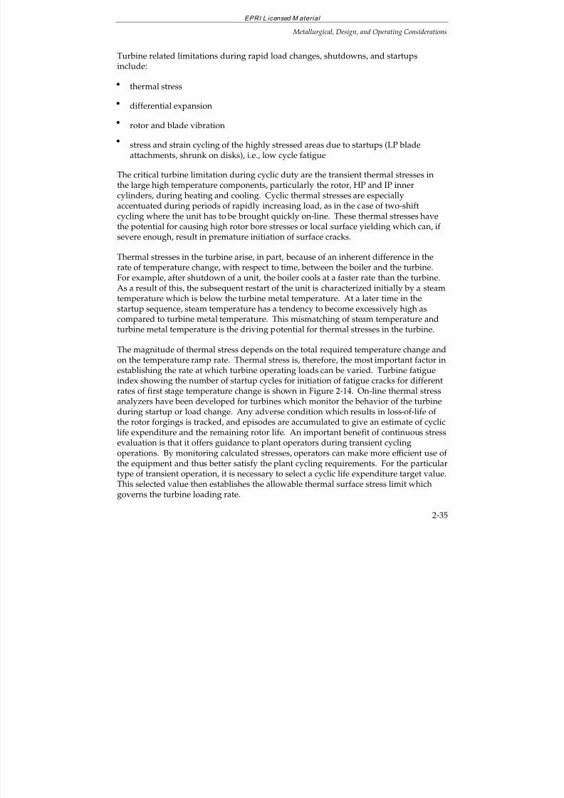
7/18/2019 EPRI Start Up, Lay Up & Shut Down Guidelines for Chemist
http://slidepdf.com/reader/full/epri-start-up-lay-up-shut-down-guidelines-for-chemist 71/256
EPRI L icensed M aterial
Metallurgical, Design, and Operating Considerations
2-35
Turbine related limitations during rapid load changes, shutdowns, and startupsinclude:
thermal stress
differential expansion
rotor and blade vibration
stress and strain cycling of the highly stressed areas due to startups (LP bladeattachments, shrunk on disks), i.e., low cycle fatigue
The critical turbine limitation during cyclic duty are the transient thermal stresses inthe large high temperature components, particularly the rotor, HP and IP innercylinders, during heating and cooling. Cyclic thermal stresses are especiallyaccentuated during periods of rapidly increasing load, as in the case of two-shift
cycling where the unit has to be brought quickly on-line. These thermal stresses havethe potential for causing high rotor bore stresses or local surface yielding which can, if severe enough, result in premature initiation of surface cracks.
Thermal stresses in the turbine arise, in part, because of an inherent difference in therate of temperature change, with respect to time, between the boiler and the turbine.For example, after shutdown of a unit, the boiler cools at a faster rate than the turbine.As a result of this, the subsequent restart of the unit is characterized initially by a steamtemperature which is below the turbine metal temperature. At a later time in thestartup sequence, steam temperature has a tendency to become excessively high as
compared to turbine metal temperature. This mismatching of steam temperature andturbine metal temperature is the driving potential for thermal stresses in the turbine.
The magnitude of thermal stress depends on the total required temperature change andon the temperature ramp rate. Thermal stress is, therefore, the most important factor inestablishing the rate at which turbine operating loads can be varied. Turbine fatigueindex showing the number of startup cycles for initiation of fatigue cracks for differentrates of first stage temperature change is shown in Figure 2-14. On-line thermal stressanalyzers have been developed for turbines which monitor the behavior of the turbineduring startup or load change. Any adverse condition which results in loss-of-life of the rotor forgings is tracked, and episodes are accumulated to give an estimate of cyclic
life expenditure and the remaining rotor life. An important benefit of continuous stressevaluation is that it offers guidance to plant operators during transient cyclingoperations. By monitoring calculated stresses, operators can make more efficient use of the equipment and thus better satisfy the plant cycling requirements. For the particulartype of transient operation, it is necessary to select a cyclic life expenditure target value.This selected value then establishes the allowable thermal surface stress limit whichgoverns the turbine loading rate.
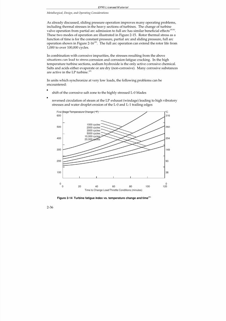
7/18/2019 EPRI Start Up, Lay Up & Shut Down Guidelines for Chemist
http://slidepdf.com/reader/full/epri-start-up-lay-up-shut-down-guidelines-for-chemist 72/256
EPRI L icensed M aterial
Metallurgical, Design, and Operating Considerations
2-36
As already discussed, sliding pressure operation improves many operating problems,including thermal stresses in the heavy sections of turbines. The change of turbinevalve operation from partial arc admission to full arc has similar beneficial effects
(49,50).
These two modes of operation are illustrated in Figure 2-15. Rotor thermal stress as afunction of time is for the constant pressure, partial arc and sliding pressure, full arc
operation shown in Figure 2-16(49)
. The full arc operation can extend the rotor life from1,000 to over 100,000 cycles.
In combination with corrosive impurities, the stresses resulting from the abovesituations can lead to stress corrosion and corrosion fatigue cracking. In the hightemperature turbine sections, sodium hydroxide is the only active corrosive chemical.Salts and acids either evaporate or are dry (non-corrosive). Many corrosive substancesare active in the LP turbine.
(65)
In units which synchronize at very low loads, the following problems can beencountered:
shift of the corrosive salt zone to the highly stressed L-0 blades
reversed circulation of steam at the LP exhaust (windage) leading to high vibratorystresses and water droplet erosion of the L-0 and L-1 trailing edges
600
500
400
300
200
100
0
Time to Change Load/Throttle Conditions (minutes)
8040 1200
First Stage Temperature Change (°F)
6020 100
1000 cycles2000 cycles
3000 cycles5000 cycles
10,000 cycles20,000 cycles
316
260
204
149
93
38
0
°C
Figure 2-14 Turbine fatigue index vs. temperature change and time(51)
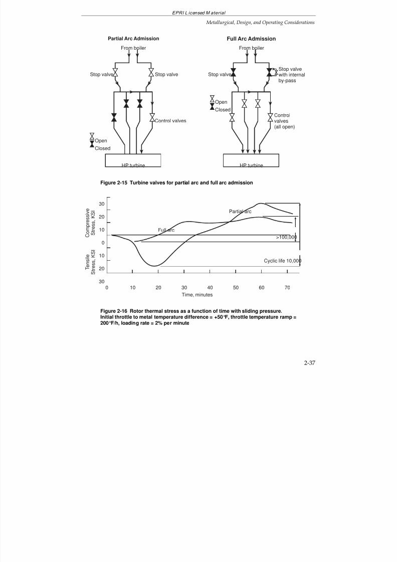
7/18/2019 EPRI Start Up, Lay Up & Shut Down Guidelines for Chemist
http://slidepdf.com/reader/full/epri-start-up-lay-up-shut-down-guidelines-for-chemist 73/256
EPRI L icensed M aterial
Metallurgical, Design, and Operating Considerations
2-37
Open
Closed
Stop valve
HP turbine
Stop valve
From boiler
Control valves
Partial Arc Admission
Stop valve
HP turbine
Stop valve
with internalby-pass
From boiler
Controlvalves(all open)
Full Arc Admission
Open
Closed
Figure 2-15 Turbine valves for partial arc and full arc admission
30
20
10
0
10
20
30
Time, minutes
10 20 30 40 50
Partial arc
Full arc
0 7060
C o m p r e s s i v e
S t r e
s s ,
K S I
T e n s i l e
S t r e s s ,
K S I
Cyclic life 10,000
>100,000
Figure 2-16 Rotor thermal stress as a function of time with sliding pressure.Initial throttle to metal temperature difference = +50°F, throttle temperature ramp =200°F/h, loading rate = 2% per minute
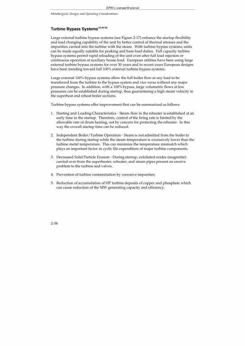
7/18/2019 EPRI Start Up, Lay Up & Shut Down Guidelines for Chemist
http://slidepdf.com/reader/full/epri-start-up-lay-up-shut-down-guidelines-for-chemist 74/256
EPRI L icensed M aterial
Metallurgical, Design, and Operating Considerations
2-38
Turbine Bypass Systems(43,49.50)
Large external turbine bypass systems (see Figure 2-17) enhance the startup flexibilityand load changing capability of the unit by better control of thermal stresses and the
impurities carried into the turbine with the steam. With turbine bypass systems, unitscan be made equally suitable for peaking and base-load duties. Full capacity turbine bypass systems permit rapid reloading of the unit even after full load rejection orcontinuous operation at auxiliary house load. European utilities have been using largeexternal turbine bypass systems for over 30 years and in recent years European designshave been trending toward full 100% external turbine bypass systems.
Large external 100% bypass systems allow the full boiler flow at any load to betransferred from the turbine to the bypass system and vice versa without any majorpressure changes. In addition, with a 100% bypass, large volumetric flows at lowpressures can be established during startup, thus guaranteeing a high steam velocity inthe superheat and reheat boiler sections.
Turbine bypass systems offer improvement that can be summarized as follows:
1. Starting and Loading Characteristics - Steam flow in the reheater is established at anearly time in the startup. Therefore, control of the firing rate is limited by theallowable rate of drum heating, not by concern for protecting the reheater. In thisway the overall startup time can be reduced.
2. Independent Boiler/Turbine Operation - Steam is not admitted from the boiler to
the turbine during startup while the steam temperature is excessively lower than theturbine metal temperature. This can minimize the temperature mismatch whichplays an important factor in cyclic life expenditure of major turbine components.
3. Decreased Solid Particle Erosion - During startup, exfoliated oxides (magnetite)carried over from the superheater, reheater, and steam pipes present an erosiveproblem to the turbine and valves.
4. Prevention of turbine contamination by corrosive impurities.
5. Reduction of accumulation of HP turbine deposits of copper and phosphate which
can cause reduction of the MW generating capacity and efficiency.
7/18/2019 EPRI Start Up, Lay Up & Shut Down Guidelines for Chemist
http://slidepdf.com/reader/full/epri-start-up-lay-up-shut-down-guidelines-for-chemist 75/256
EPRI L icensed M aterial
Metallurgical, Design, and Operating Considerations
2-39
Steamfrom boiler
superheater
Generator
CondenserControlvalve
H.P.bypassvalve
L.Pbypassvalve Condenser
Ventilatorvalve
Reverseflow valve
Interceptvalve
Reheater
L.P. bypasswater control
valve
H.P. bypasswater coltrol
valve
H.P.turbine
R.H.turbine
Figure 2-17 Turbine bypass system
Feedwater System Cleanup Loops(14,45,46,52,53,54)
Cycling units should have an auxiliary sub-loop between the condenser and the outletof the heaters to facilitate the cleanup of the preboiler cycle (Figure 2-18). The purposeof the cleanup loop is to remove the metal oxides, which enter the feedwater from thesurfaces of feedwater heaters, and the oxides which deposit on feedwater surfaces due
to the changes of pH and temperature which occur during system layup, fill, andstartup. The principal items for the successful operation of the cleanup loop are: a) alow-pressure cycle line, and b) a condensate polisher or filter to process at least 25% of the rated flow. Following an outage, the condensate must be properly treated andrecirculated through the preboiler cycle to permit deaeration and removal of suspendedsolids. Recirculation, when performed at sufficiently high velocity, removescontaminants from preboiler surfaces.
Based on experience with cleanup systems, a velocity of 0.6 m/s (2 fps) (approximately25% of the maximum continuous rating, MCR), is recommended for the current designsof feedwater heaters. Recommended procedures incorporating the bypass system,
condensate polishing, and deaeration for cyclic units have been discussed(54). Cleanuptime after long shutdowns (greater than 4 days) requires about 8 hours to reduceimpurities in the feedwater to levels suitable for use in boilers. Units started up afteroutages of less than 4 days generally require 3-4 hours to clean up the feedwater. Nopreboiler cleanup is required after a hot restart if the condensate quality meets specifiedlimits.
7/18/2019 EPRI Start Up, Lay Up & Shut Down Guidelines for Chemist
http://slidepdf.com/reader/full/epri-start-up-lay-up-shut-down-guidelines-for-chemist 76/256
EPRI L icensed M aterial
Metallurgical, Design, and Operating Considerations
2-41
Condensate Filtering and Polishing(15,45,54,67)
Removal of corrosion products (iron and copper oxides) and other impurities fromfeedwater during the cleanup operation of cyclic units is one of the best water
chemistry control measures. It can be achieved with deep-bed demineralizers,powdered-resin demineralizers, magnetic or other filters. With proper flow anddeaeration, it is possible to remove 85-95% of the suspended contaminants with amixed-bed condensate demineralizer. Optimum filtration efficiency during startup isachieved when the flow rates are greater than 0.02 m/s (25 gpm/ft
2) of resin area for
deep-bed demineralizers. Contaminant breakthrough can occur rapidly duringcleanup if suspended solids levels are high. Protection against this condition ispossible by limiting the demineralizer runs (to 24 hours or less as required) or to adifferential pressure of 345 kPa (50 psig).
Powdered-resin demineralizer filtration efficiency equals that of a deep-bed system.Design flow rates for these units are approximately 0.3 cm/s (4 gpm/ft
2) of resin area.
While these units may have less total ion exchange capacity than deep mixed-bed units,they are relatively free of incidents of "crud throw" or the release of filtered metal oxideparticulates reported with deep mixed-bed units. This is an important consideration instartup/cleanup for a cyclic unit.
Condensate polishers also remove undesirable cations and anions such as sodium,chloride, sulfate, organic acid anions, and carbonate. These impurities are at higherconcentrations during startups, and their concentration is also influenced by loadchanges during cycling. Carbonate formed from CO2 entering with air inleakage can
act as an eluent and replace the already exchanged anions from the polisher resin.
Air Inleakage and Deaeration(15,45,53-61)
During layup, startup, and cycling, large quantities of air can be introduced by:
system filling with aerated water from storage tanks,
air saturation of water in condenser and deaerator storage tank, and
increased air inleakage because a larger portion of the cycle is under vacuum.
While both tray and spray deaerators perform well at all loads (see Figure 2-19),condensers do not deaerate well until 30-50% of the thermal load is reached (see Figure2-20)
(62). Condenser deaeration can be improved by increasing the deaerating capacity
and by retrofitting steam blanketing and other means(9,57-61)
such as ensuring that themakeup water is introduced above the tubesheet.
7/18/2019 EPRI Start Up, Lay Up & Shut Down Guidelines for Chemist
http://slidepdf.com/reader/full/epri-start-up-lay-up-shut-down-guidelines-for-chemist 77/256
EPRI L icensed M aterial
Metallurgical, Design, and Operating Considerations
2-42
Air infiltration in cycling units can result from design and operation as follows(55)
:
(a) Some system designs include heater drip pumps which return drips to thecondensate or feedwater. At low loads, oxygen contents as high as 500 ppb in thedrips have been noted.
(b) Reduction of a system load to below 60% of capacity generally results in a reductionof one or two of the low pressure heaters from a positive pressure to belowatmospheric pressure. Leakage of air through the various seals results in oxygencontamination of the steam condensing on the tube bundles.
(c) Addition of undeaerated makeup water directly to the condensate or feedwatercauses extra oxygen introduction to the cycle. In base-load systems, contaminationfrom makeup sources such as storage tanks is less important since little water istransferred to and from surge tanks. In peaking units, it can be significant sincethere is considerably more shrinkage and expansion occurring in condensate surge
tanks due to frequent load changes. When undeaerated makeup or surge water isintroduced, portions of the preboiler system will become contaminated with airunless it is introduced into the deaerating section of the condenser or to a deaerator.If the makeup and surge water storage reservoirs are not resistant to oxygen attacknor protectively lined, corrosion products may also be introduced.
(d) Reduced air removal efficiency of deaerating equipment can be caused by cyclingoperation. Systems that are shut down and started frequently, such as in two-shifting and peaking operation, are subject to significant corrosion problems if aproper design to exclude air infiltration is not used by the plant designer. In this
mode, it is possible to add more oxygen into the cycle than in several months of normal base load operation. Cyclic units that may be idle overnight or on weekendsshould include the following operating and design features:
— Maintain condenser vacuum and turbine seals during brief shutdowns. Thiswill protect both low- and high-pressure condensate systems from oxygen.Turbine water glands are not effective seals at low load. Use steam seals.
— Provide auxiliary steam to pressurize the deaerator and keep deaeratorpressurized during short outages. If auxiliary steam is not available, peggingsteam from an adjacent boiler or the drum should be used. For longer outages,
nitrogen blanketing may be more convenient.
— Blanket the boiler with nitrogen or steam under pressure. The nitrogen orsteam-injection systems should be automatic with multiple points of addition on boiler, deaerator, superheaters, and feedtrain vents. While a unit that is base-loaded may be able to function with manual systems for introducing nitrogen
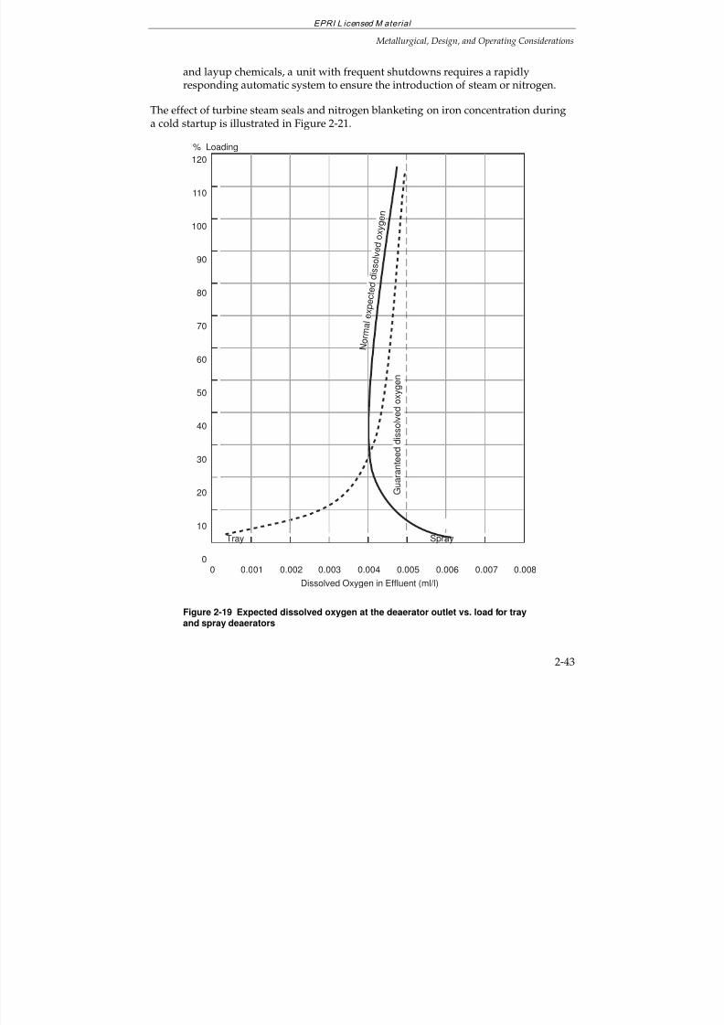
7/18/2019 EPRI Start Up, Lay Up & Shut Down Guidelines for Chemist
http://slidepdf.com/reader/full/epri-start-up-lay-up-shut-down-guidelines-for-chemist 78/256
EPRI L icensed M aterial
Metallurgical, Design, and Operating Considerations
2-43
and layup chemicals, a unit with frequent shutdowns requires a rapidlyresponding automatic system to ensure the introduction of steam or nitrogen.
The effect of turbine steam seals and nitrogen blanketing on iron concentration duringa cold startup is illustrated in Figure 2-21.
120
110
100
90
80
70
60
50
40
30
20
10
0
Dissolved Oxygen in Effluent (ml/l)
0.004 0.0060.001 0.0050.0030 0.0080.0070.002
% Loading
N o r m
a l
e x p e c
t e d d
i s s o
l v e
d o
x y g e n
G u a r a n t e e d d i s s o l v e
d o x y g e n
Tray Spray
Figure 2-19 Expected dissolved oxygen at the deaerator outlet vs. load for trayand spray deaerators
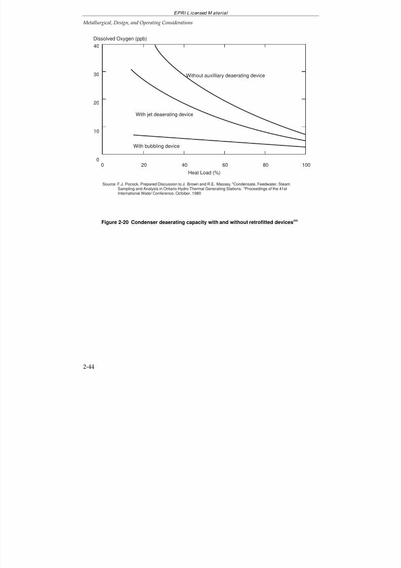
7/18/2019 EPRI Start Up, Lay Up & Shut Down Guidelines for Chemist
http://slidepdf.com/reader/full/epri-start-up-lay-up-shut-down-guidelines-for-chemist 79/256
EPRI L icensed M aterial
Metallurgical, Design, and Operating Considerations
2-44
40
30
20
10
0
Dissolved Oxygen (ppb)
With jet deaerating device
Source: F.J. Pocock, Prepared Discussion to J. Brown and R.E. Massey, "Condensate, Feedwater, SteamSampling and Analysis in Ontario Hydro Thermal Generating Stations. "Proceedings of the 41stInternational Water Conference, October, 1980
With bubbling device
Without auxilliary deaerating device
Heat Load (%)
0 20 6040 10080
Figure 2-20 Condenser deaerating capacity with and without retrofitted devices(62)
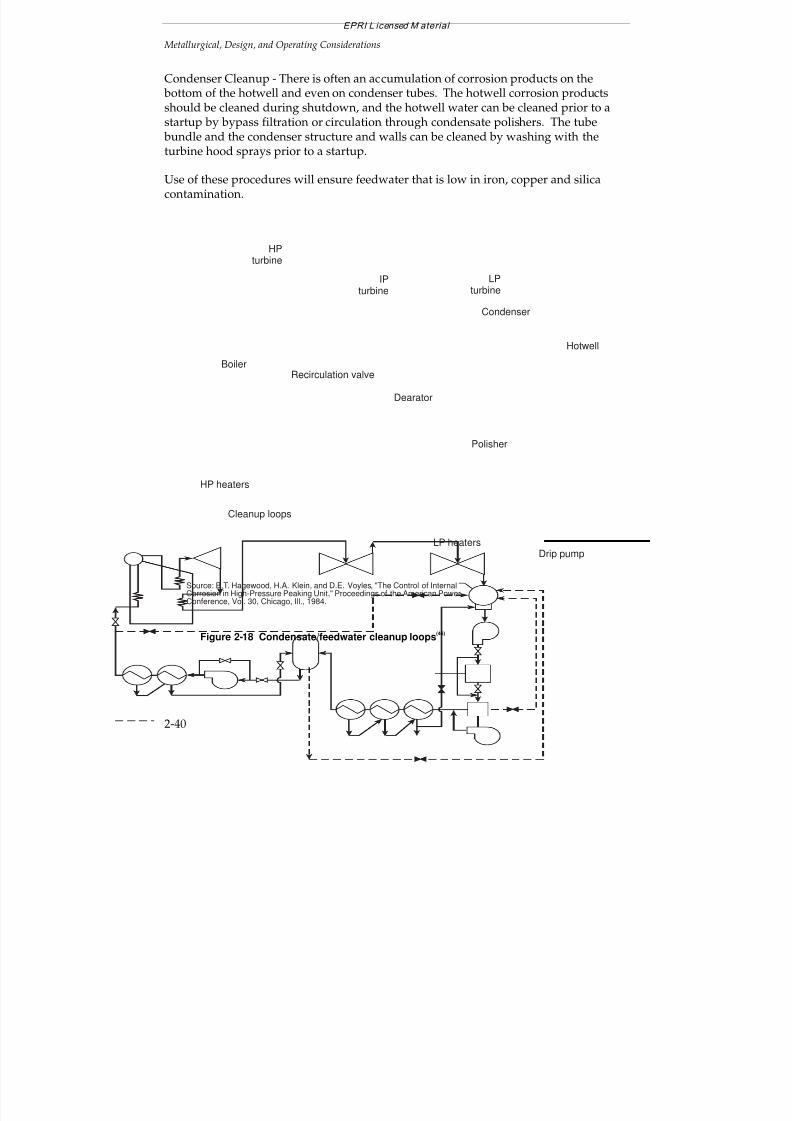
7/18/2019 EPRI Start Up, Lay Up & Shut Down Guidelines for Chemist
http://slidepdf.com/reader/full/epri-start-up-lay-up-shut-down-guidelines-for-chemist 80/256
EPRI L icensed M aterial
Metallurgical, Design, and Operating Considerations
2-40
Condenser Cleanup - There is often an accumulation of corrosion products on the bottom of the hotwell and even on condenser tubes. The hotwell corrosion productsshould be cleaned during shutdown, and the hotwell water can be cleaned prior to astartup by bypass filtration or circulation through condensate polishers. The tube bundle and the condenser structure and walls can be cleaned by washing with the
turbine hood sprays prior to a startup.
Use of these procedures will ensure feedwater that is low in iron, copper and silicacontamination.
Source: B.T. Hagewood, H.A. Klein, and D.E. Voyles, "The Control of InternalCorrosion in High-Pressure Peaking Unit," Proceedings of the American PowerConference, Vol. 30, Chicago, Ill., 1984.
Hotwell
Polisher
Condenser
Dearator
Recirculation valve
IPturbine
LPturbine
Drip pump
HP heaters
HPturbine
Boiler
LP heaters
Cleanup loops
Figure 2-18 Condensate/feedwater cleanup loops(46)
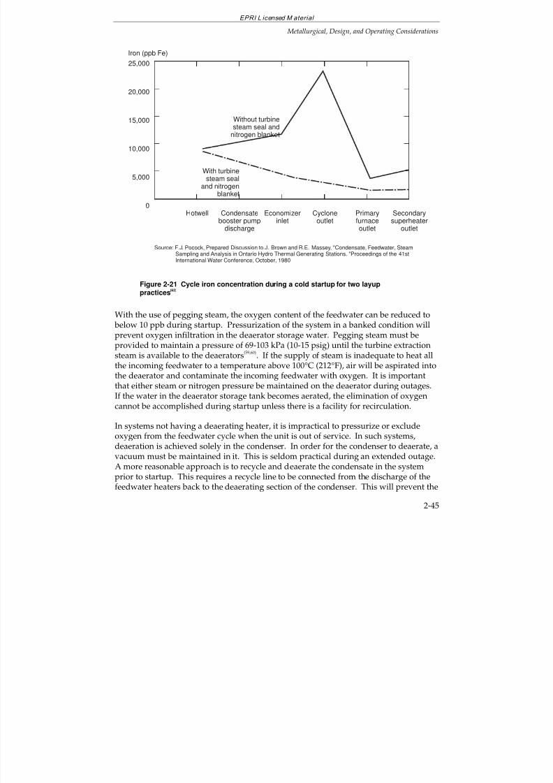
7/18/2019 EPRI Start Up, Lay Up & Shut Down Guidelines for Chemist
http://slidepdf.com/reader/full/epri-start-up-lay-up-shut-down-guidelines-for-chemist 81/256
EPRI L icensed M aterial
Metallurgical, Design, and Operating Considerations
2-45
Source: F.J. Pocock, Prepared Discussion to J. Brown and R.E. Massey, "Condensate, Feedwater, SteamSampling and Analysis in Ontario Hydro Thermal Generating Stations. "Proceedings of the 41stInternational Water Conference, October, 1980
25,000
20,000
15,000
10,000
5,000
0
Iron (ppb Fe)
Condensatebooster pump
discharge
Hotwell Economizerinlet
Cycloneoutlet
Primaryfurnaceoutlet
Without turbinesteam seal and
nitrogen blanket
With turbinesteam seal
and nitrogenblanket
Secondarysuperheater
outlet
Figure 2-21 Cycle iron concentration during a cold startup for two layuppractices
(62)
With the use of pegging steam, the oxygen content of the feedwater can be reduced to below 10 ppb during startup. Pressurization of the system in a banked condition willprevent oxygen infiltration in the deaerator storage water. Pegging steam must beprovided to maintain a pressure of 69-103 kPa (10-15 psig) until the turbine extractionsteam is available to the deaerators
(59,60). If the supply of steam is inadequate to heat all
the incoming feedwater to a temperature above 100°C (212°F), air will be aspirated intothe deaerator and contaminate the incoming feedwater with oxygen. It is importantthat either steam or nitrogen pressure be maintained on the deaerator during outages.If the water in the deaerator storage tank becomes aerated, the elimination of oxygencannot be accomplished during startup unless there is a facility for recirculation.
In systems not having a deaerating heater, it is impractical to pressurize or excludeoxygen from the feedwater cycle when the unit is out of service. In such systems,deaeration is achieved solely in the condenser. In order for the condenser to deaerate, avacuum must be maintained in it. This is seldom practical during an extended outage.A more reasonable approach is to recycle and deaerate the condensate in the systemprior to startup. This requires a recycle line to be connected from the discharge of thefeedwater heaters back to the deaerating section of the condenser. This will prevent the
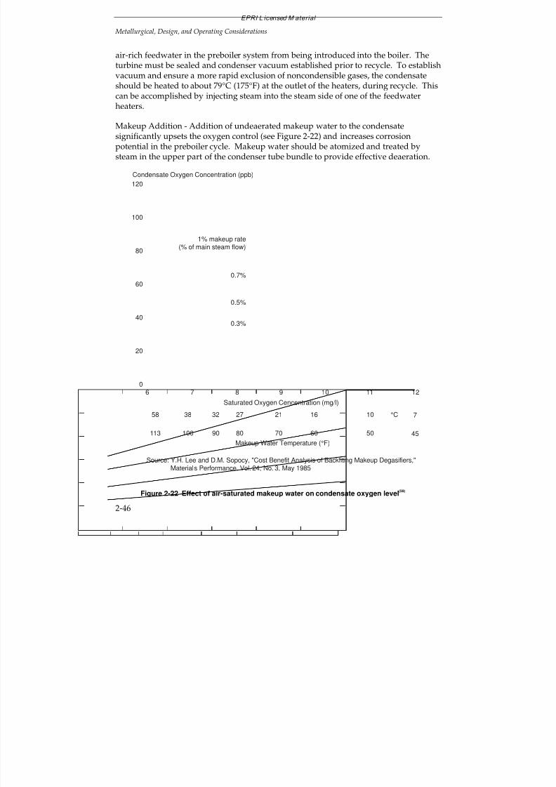
7/18/2019 EPRI Start Up, Lay Up & Shut Down Guidelines for Chemist
http://slidepdf.com/reader/full/epri-start-up-lay-up-shut-down-guidelines-for-chemist 82/256
EPRI L icensed M aterial
Metallurgical, Design, and Operating Considerations
2-46
air-rich feedwater in the preboiler system from being introduced into the boiler. Theturbine must be sealed and condenser vacuum established prior to recycle. To establishvacuum and ensure a more rapid exclusion of noncondensible gases, the condensateshould be heated to about 79°C (175°F) at the outlet of the heaters, during recycle. Thiscan be accomplished by injecting steam into the steam side of one of the feedwater
heaters.
Makeup Addition - Addition of undeaerated makeup water to the condensatesignificantly upsets the oxygen control (see Figure 2-22) and increases corrosionpotential in the preboiler cycle. Makeup water should be atomized and treated bysteam in the upper part of the condenser tube bundle to provide effective deaeration.
120
100
80
60
40
20
0
Condensate Oxygen Concentration (ppb)
0.7%
0.5%
0.3%
1% makeup rate(% of main steam flow)
Makeup Water Temperature (°F)
Saturated Oxygen Cencentration (mg/l)
Source: Y.H. Lee and D.M. Sopocy, "Cost Benefit Analysis of Backfiting Makeup Degasifiers," Materials Performance, Vol. 24, No. 3, May 1985
6 7 8 109 11 12
113 100 90 7080 5060 45
58 38 32 2127 1016 7°C
Figure 2-22 Effect of air-saturated makeup water on condensate oxygen level(59)
7/18/2019 EPRI Start Up, Lay Up & Shut Down Guidelines for Chemist
http://slidepdf.com/reader/full/epri-start-up-lay-up-shut-down-guidelines-for-chemist 83/256
EPRI L icensed M aterial
Metallurgical, Design, and Operating Considerations
2-47
At startup, or at low loads, the heater drips may contain as much as 500 ppb of oxygenand, therefore, they should be introduced into the condenser through atomizingdevices. Drains at temperatures below saturated steam temperature should beintroduced above the tube bundle; drains with temperatures above saturated steamtemperature should be introduced between the tube bundle and the hot well.
Condenser Deaeration
Efficient air removal is essential for achieving good condenser deaeration at all loads.Most condensers provide adequate deaeration at high loads; however, at low loads oron startup of peaking or two-shifting units, the deaeration is marginal (see Figure 2-20).It can be improved by retrofitting steam sparging and other means.
The prime factors affecting condenser deaeration at low loads are the temperature riseof the circulating water, air inleakage, and deaerating capacity of the vacuum pumps or
air ejectors. At low loads, the temperature rise of the cooling water across thecondenser tubes is less than at full load. This results in a reduced condenser pressureand corresponding saturated steam temperature causing a reduction in mass-steamcondensation area and an increase in the air cooler area. Under these conditions, anincreased oxygen concentration is caused by subcooling. Since air ejector capacity isconstant, and normally designed for full-load operation, more wet steam and less gas isejected. The remainder of the gas accumulates within the condenser shell, increasingthe partial pressure of the gas throughout the bundle.
Tests have been run which indicate that air inleakage at 25% load can be double that atfull load. At low loads, or startup, it is necessary to remove the air to ensure acondenser vacuum. Air ejector overloads lead to increased condenser pressure anddissolved oxygen content, which in turn promotes corrosion in the cycle. Thiscondition and that due to insufficient sweeping of air deep in the tube bundle, can beobviated by using an additional vacuum pump or ejector. With proper design, 12.7mm (0.5 in.) or as low as 6.35 mm (0.25 in.) Hg, absolute suction pressure can beattained.
2.6 ALTERNATIVE WATER TREATMENT CHEMICALS(3,63,64)
During the past 15 years, many new amine, oxygen scavengers, and polymericdispersants have been introduced. These chemicals are mostly used in industrial steamcycles and their use in high pressure utility units is controversial. All types of utilityunits can be operated with the water treatments and chemicals recommended in EPRIguidelines. The main concern with the use of the alternative organic water treatmentchemicals is their thermal decomposition (breakdown) and production of organic acidsand carbon dioxide.
7/18/2019 EPRI Start Up, Lay Up & Shut Down Guidelines for Chemist
http://slidepdf.com/reader/full/epri-start-up-lay-up-shut-down-guidelines-for-chemist 84/256
EPRI L icensed M aterial
Metallurgical, Design, and Operating Considerations
2-48
Before applying these new chemicals, their properties should be carefully determinedand experience with each should be verified. Then, within a few weeks of the firstapplication of the new chemical, the cycle chemistry should be analyzed in much moredetail than during the normal operation and any breakdown products should beidentified
(3).
The selected treatment should protect all cycle components and prevent generation of corrosion products, and general and localized corrosion. These chemicals and their breakdown products should be compatible with all cycle component materials and thelayup practices, and with all environmental and health regulations. Decomposition of organic compounds at the elevated and high temperatures in feedwater and boilers canlead to increased feedwater and steam cation conductivity and reduced pH. Most of the applications are for low- and medium-pressure industrial units, but some of thesechemicals are also being used in utility cycles. The use of some of these products canlead to corrosion, buildup of deposits, and other problems. It should be kept in mindthat the overall philosophy of the EPRI fossil plant cycle chemistry program is to keepthe cycle as pure as possible with as few chemical additions as possible.
The alternative water treatment chemicals (all organic) fall into the followingcategories:
neutralizing and filming amines for feedwater, steam, and condensate
reducing agents (oxygen scavengers)
dispersants and chelating agents for prevention of boiler scale and removal of
hardness and corrosion products (these should only be considered and used in lowpressure (<1000 psi, 7MPa) units)
There are hundreds of formulations of the above chemicals and their mixtures.
To evaluate the effects of any water treatment chemical, data pertinent to its chemicaltransport, decomposition temperature and products, cycle material corrosion, depositand scale buildup, and analytical interferences should be known. These needed datainclude:
hydrothermal stability in the cycle
kinetics of reactions
decomposition products and their effects
analytical interferences
7/18/2019 EPRI Start Up, Lay Up & Shut Down Guidelines for Chemist
http://slidepdf.com/reader/full/epri-start-up-lay-up-shut-down-guidelines-for-chemist 85/256
EPRI L icensed M aterial
Metallurgical, Design, and Operating Considerations
2-49
how to monitor/analyze
toxicity of the product, decomposition products, deposits, etc.
measured effects on pH, specific conductivity, cation conductivity, iron, and copper
concentrations in the feedwater, boiler water and steam
stability in chemical addition tanks and storage containers
solubility and volatility of the chemical and its decomposition products
behavior of dried-out solutions (deposits in reheaters, superheaters, turbines, valve“gluing”)
behavior under short- and long-term layup conditions and during startup(decomposition - acid formation, scale formation, disposal, etc.)
The utility users of water treatment chemicals need to know the pressure andtemperature range of their application and the nature and behavior of thedecomposition products. These are not usually supplied by the chemicalmanufacturers, and a utility will need to perform comprehensive monitoring beforeconsidering their application
(3).
2.7 REFERENCES AND BIBLIOGRAPHY FOR SECTION 2
1. Interim Consensus Guidelines on Fossil Plant Cycle Chemistry. EPRI CS-4629,
RP2712-1, June 1986.
2. Guidelines on Cycle Chemistry for Fluidized-Bed Combustion Plants. EPRI TR-102976, September 1993.
3. Selection and Optimization of Boiler Water and Feedwater Treatments for FossilPlants. EPRI TR-105040, March 1997.
4. Cycle Chemistry Corrosion and Deposition: Correction, Prevention, and Control.EPRI TR-103038, December 1993.
5. “Transport of Chemicals in the Steam Cycle.” In Ref. 15.
6. O. Jonas. “Transport of Chemicals in the Steam Cycle”. Paper No. 245,Corrosion/85, NACE, March 25, 1985, Boston.
7. Survey of Cyclic Load Capabilities of Fossil-Steam Generating Units, EPRI EL-975,Final Report, February 1979.
7/18/2019 EPRI Start Up, Lay Up & Shut Down Guidelines for Chemist
http://slidepdf.com/reader/full/epri-start-up-lay-up-shut-down-guidelines-for-chemist 86/256
EPRI L icensed M aterial
Metallurgical, Design, and Operating Considerations
2-50
8. Cycling Ability to Large Generating Units Workshop, EPRI WS-77-50, November1977.
9. “Proceedings: 1983 Fossil Plant Cycling Workshop.” EPRI Report CS-3979, April1985.
10. “Proceedings: 1985 Fossil Plant Cycling Workshop.” EPRI Report CS-4723,September, 1986.
11. “Proceedings: 1987 Conference of Fossil Plant Cycling,” EPRI Report CS-6048,December, 1988.
12. “Fossil Plant Cycling.” EPRI Conference, Washington, D.C., December 4-7, 1990.
13. Cycling of High-Pressure Steam Power-Generating Units with Drum Boilers. EPRICS-2340, Final Report, April 1982.
14. Improvement of Chemistry Control During Startup of Fossil Units. ASMEWorkshop, St. Louis, MO, April 9-10, 1997.
15. The ASME Handbook on Water Technology for Thermal Power Systems. PaulCohen, Editor-in-Chief. EPRI Research Project RP-1958-1, ASME, 1989.
16. Combustion - Fossil Power Systems, Combustion Engineering, Inc. 1981.
17. A. F. Armor and F. K. L. Wong. “Fossil Plant Cycling Program.” In Ref. 9.
18. O. Jonas. “Understanding Steam Turbine Corrosion”, Paper No. 55, Corrosion/84,NACE April 2-6, 1984, New Orleans.Also: “Steam Turbine Corrosion,” Materials Performance, 24, 2, February 1985, pp.9-18.
19. R. Garnsey, Combustion, Vol. 52, No. 2, p. 39, 1980.
20. G. M. W. Mann. “The Oxidation of Iron Base Alloys Containing Less Than 12% Crin High Temperature Aqueous Solutions.” in High Temperature, High PressureElectrochemistry in Aqueous Solutions, NACE, Houston, Texas, 1976. pp. 34-47.
21. G. M. W. Mann. “History and Causes of On-Load Waterside Corrosion.” Br.Corrosion J. 12 (no. 1, January 1977): pp. 6-14.
22. State-of-Knowledge of Copper in Fossil Plant Cycles. EPRI TR-108460, September1997.
23. Metals Handbook, Volume 19 - Fatigue and Fracture, ASM International 1986.
7/18/2019 EPRI Start Up, Lay Up & Shut Down Guidelines for Chemist
http://slidepdf.com/reader/full/epri-start-up-lay-up-shut-down-guidelines-for-chemist 87/256
EPRI L icensed M aterial
Metallurgical, Design, and Operating Considerations
2-51
24. Metals Handbook, Volume 13 - Corrosion, ASM International 1987.
25. B. Dooley and W. McNaughton. Boiler Tube Failures: Theory and Practice. EPRIBook, TR-105261, 1996.
26. D. D. Macdonald and G. A. Cragnolino. “Corrosion of Steam Cycle Materials.” InRef. 15.
27. J. Mathews. “The Importance of Startup Chemistry to the Long-term Reliability of Power Generating Equipment.” In Ref. 14.
28. O. Jonas, et al. “Copper Deposition and MW Loss Problem Solutions.” Paperpresented at the International Water Conference, Pittsburgh, October 1996.
29. Corrosion Product Transport in a Cycling Fossil Plant. EPRI Report CS-5033,February, 1987.
30. Cycle Chemistry Guidelines for Fossil Plants: Oxygenated Treatment. EPRI TR-102285, December 1994.
31. Cycle Chemistry Guidelines for Fossil Plants: All-Volatile Treatment. EPRI TR-105041, April 1996.
32. Monitoring & Diagnostic Center: An Overview of Operating Activities. EPRI GS-7407, July 1991, pp. 4-22 to 4-38.
33. Boiler Stress and Condition Analyzer. EPRI, RN6315B(1), August 1986.
34. G. Touchton, et al. “Predictive Maintenance for the '90s: EPRI Keynote.” EPRIFourth Incipient Failure Detection Conference, Philadelphia, PA, October, 1990.
35. A. F. Armor. “On-Line Diagnostics for Fossil Power Plants: The Promise and theReality.” EPRI Workshop on Incipient Failure Detection for Fossil Plants, Hartford,CT, August 1982.
36. O. Jonas. “Incipient Failure Detection and Predictive Maintenance.” Power, January 1992, p. 61.
37. O. Jonas. “On-Line Diagnosis of Turbine Deposits and First Condensate.”Pittsburgh, PA, Oct. 31-Nov. 1-2, 1994.
38. O. Jonas. “Monitoring of Superheater and Reheater Exfoliation and Steam Blow.”56th International Water Conference, Pittsburgh, October 1995.
7/18/2019 EPRI Start Up, Lay Up & Shut Down Guidelines for Chemist
http://slidepdf.com/reader/full/epri-start-up-lay-up-shut-down-guidelines-for-chemist 88/256
EPRI L icensed M aterial
Metallurgical, Design, and Operating Considerations
2-52
39. B. E. Laney, et al. “Supercritical Unit Boiler Circuitry and Control SystemModifications for Improved Unit Turndown Capability.” In Ref. 9.
40. W. P. Gorzegno. “Retrofitting High Efficiency Steam Generators for CyclingService.” In Ref. 9.
41. I. Martinez, et al. “Supercritical Steam Generator Designs for Sliding PressureOperation.” American Power Conference, Chicago, 1981.
42. H. Termuehlen. “Variable-Pressure Operation and External Turbine BypassSystems to Improve Power Plant Cycling Performance.” ASME paper 79-JPGC-Pwr-9, Joint Power Generation Conference, Charlotte, NC, Oct. 1979.
43. G. P. Schatzmann. “Economic Peak-load Coverage by Retrofitting Existing PowerPlants.” In Ref. 9.
44. Study of Universal Pressure Boiler for Cycling Operations. EPRI CS-2348, June1982.
45. F. Gabrielli, et al. “Water Chemistry Aspects of Cyclic Operation for Older HighPressure Drum-Type Boilers.” In Ref. 9.
46. B. T. Hagewood, et al. “The Control of Internal Corrosion in High Pressure PeakingUnit.” Proceedings of the American Power Conference, Vol. 30, Chicago, IL, 1984.
47. The Spalling of Steam-Grown Oxide from Superheater and Reheater Tube Steels.EPRI FP-686, February 1979.
48. Solid Particle Erosion Technology Assessment. EPRI TR-103552, December 1993.
49. D. D. Rosard and W. G. Steltz. “Assessment of Fossil Steam Bypass Systems.” InRef. 9.
50. C. R. Ernest and W. G. Gorman. “Upgrading Steam Turbine-Generators for CyclingOperation.” In Ref. 9.
51. J. Bellows. “Startup Procedures and Limits: A Manufacturer's Perspective.” In Ref.14.
52. R. L. Coit. “Balance of Plant Options for Cyclic Duty Operation.” In Ref. 9.
53. W. A. Micek and K. L. Atwood. “Design Factors in Water Chemistry Control forBoilers in Cyclic Service.” Proceedings of the American Power Conference 41, 1979,pp. 905-911.
7/18/2019 EPRI Start Up, Lay Up & Shut Down Guidelines for Chemist
http://slidepdf.com/reader/full/epri-start-up-lay-up-shut-down-guidelines-for-chemist 89/256
EPRI L icensed M aterial
Metallurgical, Design, and Operating Considerations
2-53
54. F. Gabrielli, and W. R. Sylvester. “Water Treatment Practices for Cyclic Operationof Utility Boilers.” International Water Conference, Pittsburgh, PA, October 31-November 2, 1978.
55. H. Grabowski. “Management of Cycle Chemistry.” In Ref. 15.
56. O. Jonas. “Deaerators, An Overview of Design, Operation, Experience, and R & D.”Proceedings of the Amer. Power Conference, Vol. 49, p. 979, 111. Institute of Technology, 1987.
57. W. Pearl, et al. “Deoxygenation in Cycling Fossil Plants.” 1990 Conference onFossil Plant Cycling, Washington, DC, December, 1990.
58. O. Jonas. “Controlling Oxygen in Steam Generating Systems.” Power, May 1990.
59. Y. H. Lee and D. M. Sopocy. “Cost Benefit Analysis of Backfitting Makeup
Degasifiers.” Materials Performance, Vol. 24, No. 3, May 1985.
60. I. Oliker. “Deaeration.” In Ref. 15.
61. R. Coit. “Condensers.” In Ref. 15.
62. F. J. Pocock, prepared discussion of the paper: J. Brown and R. E. Massey.“Condensate, Feedwater, Steam Sampling and Analysis in Ontario Hydro ThermalGenerating Stations.” Proceedings of 41st International Water Conference, October,1980.
63. “Use of Organic Water Treatment Chemicals.” VGB Conference, OrganischeKonditionierungs-und Sauerstoffbindemittel, Lahnstein, Germany, March 1994.
64. O. Jonas. “Beware of Organic Impurities in Steam Power Systems.” Power, 126, 9,pp. 103-107, September 1982.
65. T. McCloskey, B. Dooley and W. McNaughton. “Steam Path Failures: Theory andPractice.” Two Volume EPRI Book TR-108943.
66. R.B. Dooley, J. Mathews, R. Pate and J. Taylor, “Optimum Chemistry for ‘All-Ferrous’ Feedwater Systems: Why Use an Oxygen Scavenger?”. Proceedings: 55th
International Water Conference. Engineers Society of Western Pennsylvania. 1994.
67. Condensate Polishing Guidelines. TR-104422. Palo Alto, Calif.: Electric PowerResearch Institute, September 1996.

7/18/2019 EPRI Start Up, Lay Up & Shut Down Guidelines for Chemist
http://slidepdf.com/reader/full/epri-start-up-lay-up-shut-down-guidelines-for-chemist 90/256
EPRI L icensed M aterial
Metallurgical, Design, and Operating Considerations
2-54
7/18/2019 EPRI Start Up, Lay Up & Shut Down Guidelines for Chemist
http://slidepdf.com/reader/full/epri-start-up-lay-up-shut-down-guidelines-for-chemist 91/256
EPRI L icensed M aterial
3-1
3
GENERAL ASPECTS COMMON TO MOST UNITS
3.1 DEFINITIONS
Cycling
Cycling is a load following operation. The unit load fluctuates with system demand,with the unit synchronized at very low loads during low-demand periods. A typicalload variation for cycling units might range from 30% to 100% of design capacity.
Peaking is a form of cycling in which the unit is operated only during peak powerdemand periods. At off-peak hours the unit is on hot or cold standby, depending uponthe estimated time between restarts. Two-shift operation is typical of peaking units,which generally furnish power for the morning and evening high demand hours.
Duration of Shutdown
The duration and description of shutdown periods have different definitions within the
various utility systems. For the purposes of this Guideline document, shutdownperiods are defined as follows:
Short-Term Shutdown (Wet)
Overnight to through-a-weekend. This might be typical of cycling-type operation. Thechemistry conditions for boiler water and pre-boiler systems are usually kept in thenormal operating range. The boiler should be full and under pressure.
Intermediate Shutdown (Wet and Dry)
This condition applies for periods extending more than a weekend and up to one week.It could typify a shutdown for equipment repair of modest complexity.
Under wet conditions the chemistry is maintained in the normal operating range andthe boiler is allowed to cool. Positive nitrogen pressure is applied and maintained toprevent air-ingress as pressure decays below positive pressure.
7/18/2019 EPRI Start Up, Lay Up & Shut Down Guidelines for Chemist
http://slidepdf.com/reader/full/epri-start-up-lay-up-shut-down-guidelines-for-chemist 92/256
EPRI L icensed M aterial
General Aspects Common to Most Units
3-2
Under dry conditions (needed for such operations as boiler tube repair) the boiler andassociated systems are drained hot and purged with nitrogen to remove all traces of moisture. Air-ingress is controlled by maintaining a positive nitrogen blanket on the boiler, superheater, and associated steam spaces until moisture is removed and themetal cools.
For safety reasons nitrogen must be purged from all areas being serviced beforepersonnel ingress for repairs.
Longterm Shutdown (Wet and Dry)
This condition applies when the unit is out-of-service for more than one week. Thiscould include major equipment repair, planned outage, or a unit mothballing scenario.
Under wet conditions, hydrazine concentrations are elevated, pH is maintained above 9(25°C, 77°F) and a positive nitrogen pressure is maintained to exclude air from un-
flooded spaces.
Under dry conditions, the hot boiler is drained and purged of all moisture withnitrogen. A positive pressure of nitrogen is maintained in the boiler and associatedsteam spaces until the boiler cools. Nitrogen blankets may be maintained for extendedperiods. Alternatively the unit may be stored indefinitely under properly controlleddry dehumidified conditions.
Peaking
If the unit is utilized for peaking service, the applicable hot-standby or short-termlayup condition with properly controlled chemistry should be utilized.
Again, the length of shutdown plays a major role in the type of layup procedureselected (See Layup Section 4). The rapidity with which units can be returned toservice may place constraints on how the unit is shut down or the procedures used forlayup.
Forced Shutdown
There are several types of situations which would demand an emergency shutdown.Each situation may affect the type of chemistry treatment which can be provided andthe method of layup
(1a):
7/18/2019 EPRI Start Up, Lay Up & Shut Down Guidelines for Chemist
http://slidepdf.com/reader/full/epri-start-up-lay-up-shut-down-guidelines-for-chemist 93/256
EPRI L icensed M aterial
General Aspects Common to Most Units
3-3
System Failure but no Equipment Failure
A system failure may be caused by a fault on the system over which the utility has littlecontrol, such as a system blackout or loss of a critical transmission line. This wouldresult in rapid shutdown without the possibility of close chemical control. Most layups
under these conditions would be short-term.
Major Equipment Failure
A major equipment failure might include boiler tube failures, turbine vibration, boilerfeed pump malfunction, etc. This type of failure would normally result in rapidshutdown without the possibility of close chemical control. Layup would probably belongterm.
3.2 USE OF POLISHERS AND CONDENSATE FILTRATION
Condensate Polishing and/or Filtration (1b)
Condensate polishing and/or filtration is a definite asset for all operating units, andparticularly those in cycling operation. These options materially reduce startup timesand prevent high concentrations of corrosion products from entering the boiler. Acomplete discussion of the benefits of condensate polishing can be found in the EPRICondensate Polishing Guidelines
(2).
Clean-up loops (Figure 2-18) that include either or both condensate polishing and
filtration provide for rapid cleanup of the pre-boiler system and will reduce startuptime by removing corrosion products and other contaminants such as silica.
Makeup Water Treatment
The makeup water quality is especially important with frequent startups/shutdowns, because of the additional water usage required during these operations. The makeupwater limits provided in the phosphate
(3), AVT
(4) and OT
(5) guidelines are comparable to
the requirements for the condensate cycle.
Properly designed and operated makeup systems are generally reliable in providing aproduct meeting the requirements of the plant with respect to both quantity and purity.Unfortunately, the makeup system is sometimes taken for granted. During cycling andpeaking operations, it is vitally important that routine surveillance of the makeup plantis maintained to meet standard makeup water quality requirements
(6).
7/18/2019 EPRI Start Up, Lay Up & Shut Down Guidelines for Chemist
http://slidepdf.com/reader/full/epri-start-up-lay-up-shut-down-guidelines-for-chemist 94/256
EPRI L icensed M aterial
General Aspects Common to Most Units
3-4
3.3 MONITORING IMPORTANCE AND REQUIREMENTS
Sampling and Monitoring
Monitoring of core parameters (see Table 1-1) is essential for transient operation.During shutdown, additional monitoring of iron and copper, and monitoring of thewater treatment additives used during layup is necessary. Water chemistry and othermonitoring during layup is described in Section 4-6.
During startup, additional monitoring may include more frequent sampling for ironand copper, analysis for organics, and analysis of the makeup and the condensatestorage tank water. Membrane Filter Charts and membrane filtering of feedwater have been found to be a rapid and useful method of evaluating corrosion product transportduring start-up and re-starts
(7). This is a very simple and available method which can
provide a direct indication of whether the shutdown and layup procedures have been
successful.
Sampling Problems
During low load operation, pressure and flow characteristics of the sampled streamschange and often there is insufficient sample flow to analyzers and grab samplingports. In improperly designed sampling systems, the changing sample flows can resultin sampling errors up to several hundred percent. The sampling system characteristicsneed to be tested and the sampling system improved if necessary, particularly forcycling and peaking units.
During startups, re-starts, rapid load changes, significant amounts of corrosionproducts can be transported from the pre-boiler system to the boiler
(9-11). After extended
outages and where systems have been opened for inspection and repair, the quantitiesmay be large (even in the ppm range). Figure 3-1 shows an example of iron and copperlevels measured at the economizer inlet of a drum unit startup
(9,10). Thus, it is very
important to improve the sampling systems for cycling and peaking service in orderthat a proper assessment of corrosion product transport to the boiler can be madeduring this type of operation
(8).
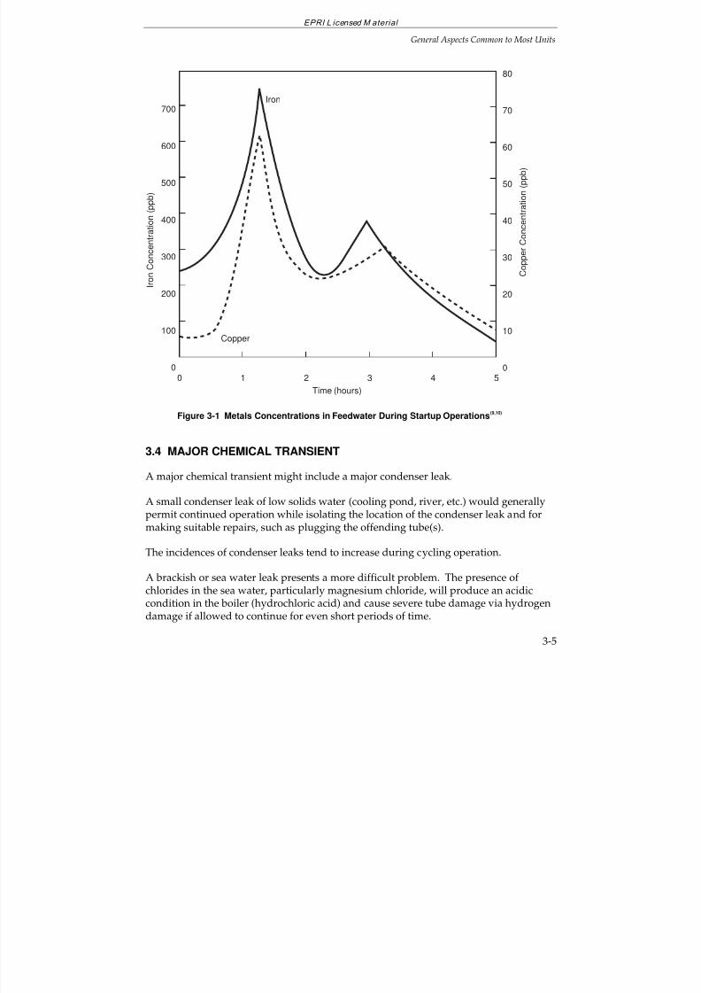
7/18/2019 EPRI Start Up, Lay Up & Shut Down Guidelines for Chemist
http://slidepdf.com/reader/full/epri-start-up-lay-up-shut-down-guidelines-for-chemist 95/256
EPRI L icensed M aterial
General Aspects Common to Most Units
3-5
700
600
500
400
300
200
100
0
C o
p p e r C o n c e n t r a t i o n ( p p b )
I r o n C
o n c e n t r a t i o n ( p p b )
Copper
Iron
Time (hours)
80
70
60
50
40
30
20
10
00 1 2 3 4 5
Figure 3-1 Metals Concentrations in Feedwater During Startup Operations(9,10)
3.4 MAJOR CHEMICAL TRANSIENT
A major chemical transient might include a major condenser leak.
A small condenser leak of low solids water (cooling pond, river, etc.) would generallypermit continued operation while isolating the location of the condenser leak and formaking suitable repairs, such as plugging the offending tube(s).
The incidences of condenser leaks tend to increase during cycling operation.
A brackish or sea water leak presents a more difficult problem. The presence of chlorides in the sea water, particularly magnesium chloride, will produce an acidiccondition in the boiler (hydrochloric acid) and cause severe tube damage via hydrogendamage if allowed to continue for even short periods of time.
7/18/2019 EPRI Start Up, Lay Up & Shut Down Guidelines for Chemist
http://slidepdf.com/reader/full/epri-start-up-lay-up-shut-down-guidelines-for-chemist 96/256
EPRI L icensed M aterial
General Aspects Common to Most Units
3-6
With the availability of a condensate polisher on the unit, an orderly shutdown may bepermitted during sea water leakage, especially if a deep bed polisher is provided, andif the sea water leak is small. Utilities with deep bed polishers should retain one ormore beds in the hydrogen form to provide additional capacity to handle the condenserleak.
Powdered resin condensate polishers contain less capability for removal of dissolvedimpurities than deep bed polishers
(2). If the leak is small, the use of powdered resin
systems may permit an orderly unit shutdown.
Chemistry monitoring is especially important when a sea water condenser leak issuspected. Boiler water pH is critical and condensate cation conductivity and sodiumwill assist in estimating the extent of the leak
(8).
In any event, the unit should be shut down to repair the condenser leak. Depending onan evaluation of cycle and boiler chemistry, the shutdown will be immediate ororderly, as outlined above. If the unit has a divided waterbox then the load could bereduced to half depending on the seriousness of the leak.
Chemical Transients and Equipment Failures
Chemical contamination may occur from several sources:
— Makeup Demineralizer
Both caustic and acid contamination of the boiler have been reported as a result of
demineralizer regenerant solutions inadvertently entering the system throughequipment malfunctions or operator error.
— Deep Bed Polisher
Contamination similar to that from the makeup demineralizer (above) can occurand for the same reasons.
— Chemical Cleaning
Acidic contamination has been reported after chemical cleanings because of improper rinsing. Superheater contamination has been reported caused byinadequate superheater isolation procedures.
Intrusion of chemical contamination from the above (and possibly other) sourcesrequires immediate unit shutdown, draining and flushing the unit. Inspection of critical areas of the system (boiler, superheater, turbine, etc.) should be performed toassess the effects of chemical intrusion on the system. Chemical cleaning of the boiler,superheater and turbine may be required depending upon the results of the inspection.
7/18/2019 EPRI Start Up, Lay Up & Shut Down Guidelines for Chemist
http://slidepdf.com/reader/full/epri-start-up-lay-up-shut-down-guidelines-for-chemist 97/256
EPRI L icensed M aterial
General Aspects Common to Most Units
3-7
Equipment repairs may also be required. In such case, a longterm layup will benecessary. (See Layup Section 4.)
The use of a condensate/feedwater cleanup loop, such as shown in Figure 2-18, ishighly effective in removing contaminants from the cycle, permitting more rapid starts
and less contamination entering the boiler.
3.5 MINIMIZATION OF AIR IN-LEAKAGE
Minimization of air inleakage (oxygen and carbon dioxide) is essential to preventincreased corrosion during startup. Oxygen and carbon dioxide can be controlled byone or more of the following measures:
Makeup water deaeration
Protecting condensate storage tanks from air
— Floating covers
— Diaphragms
— Nitrogen Purge
Maintaining condenser vacuum during shutdowns
Hotwell sparging
Use of a heat cycle deaerator
Proper maintenance procedures, particularly for equipment operating undervacuum conditions
Optimization of air removal equipment
Steam or nitrogen blanketing steam-side surfaces during downtime periods
To minimize corrosion, the dissolved oxygen content at the economizer inlet and boiler
water during startup and before firing should be less than 100 ppb, the iron in thefeedwater should be less than 100 ppb and the copper in the feedwater should be lessthan 10 ppb.
7/18/2019 EPRI Start Up, Lay Up & Shut Down Guidelines for Chemist
http://slidepdf.com/reader/full/epri-start-up-lay-up-shut-down-guidelines-for-chemist 98/256
EPRI L icensed M aterial
General Aspects Common to Most Units
3-8
3.6 CORRECTIVE ACTIONS
Typical corrective actions to respond to out-of-specification steam and/or waterchemistry conditions for drum units on PT, EPT, AVT, OT and CT are presented in the“Corrective Actions” sections of the respective EPRI guidelines
(3-5,12). Individual
corrective action tabulations are given for the following:
Makeup treatment system effluent
Condensate storage tank effluent
Condenser leak detection trays
Air removal system exhaust
Condensate pump discharge
Deaerator inlet
Deaerator outlet
Economizer inlet
Boiler water
Reheat steam
For the specific suggestions during shutdown and startup, the reader is referred toSections 5–8 in this Guideline.
3.7 HOW TO USE THE PRESENT EPRI GUIDELINES FOR CYCLING
OPERATION
All the current EPRI Guidelines(3-5,12)
for drum units present a series of curves for boilerwater concentrations of sodium, chloride, sulfate and silica vs. boiler drum pressurewhich are considered satisfactory for “normal operation,” consistent with longtermsystem reliability. The AVT Guidelines
(4) also provide similar information for cation
conductivity. The Guidelines for once-through units also present “normal” operatinglimits on cycle diagrams. Four additional action levels are also recognized:
Action Level 1
There is potential for the accumulation of contaminants and corrosion. Returnvalues to normal levels within 1 week.
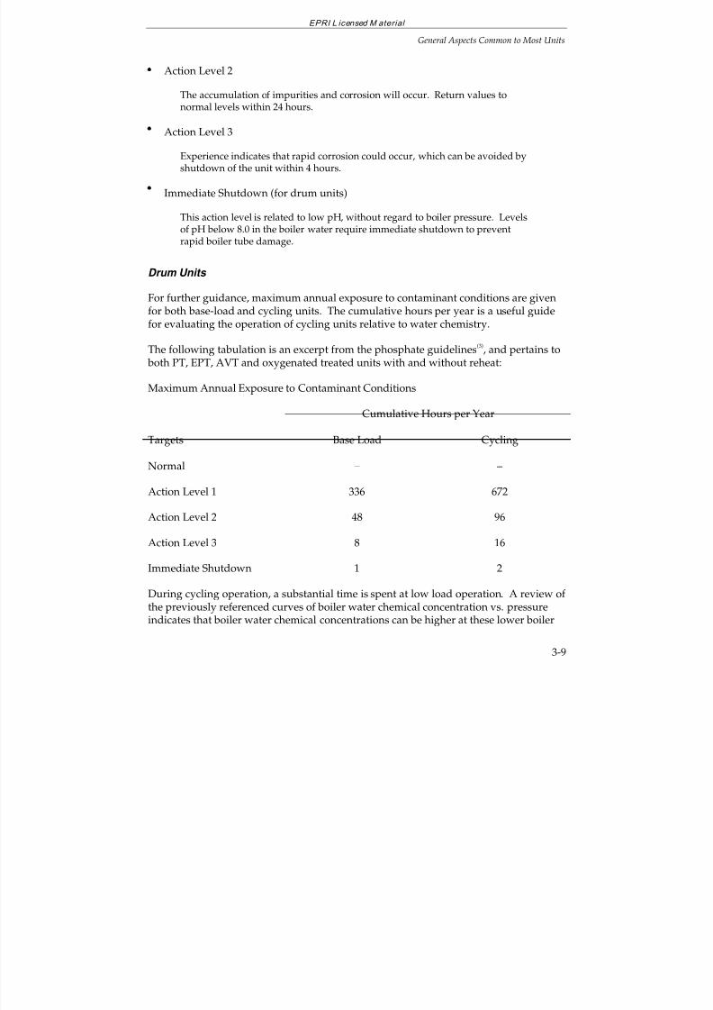
7/18/2019 EPRI Start Up, Lay Up & Shut Down Guidelines for Chemist
http://slidepdf.com/reader/full/epri-start-up-lay-up-shut-down-guidelines-for-chemist 99/256
EPRI L icensed M aterial
General Aspects Common to Most Units
3-9
Action Level 2
The accumulation of impurities and corrosion will occur. Return values tonormal levels within 24 hours.
Action Level 3
Experience indicates that rapid corrosion could occur, which can be avoided byshutdown of the unit within 4 hours.
Immediate Shutdown (for drum units)
This action level is related to low pH, without regard to boiler pressure. Levelsof pH below 8.0 in the boiler water require immediate shutdown to preventrapid boiler tube damage.
Drum Units
For further guidance, maximum annual exposure to contaminant conditions are givenfor both base-load and cycling units. The cumulative hours per year is a useful guidefor evaluating the operation of cycling units relative to water chemistry.
The following tabulation is an excerpt from the phosphate guidelines(3)
, and pertains to both PT, EPT, AVT and oxygenated treated units with and without reheat:
Maximum Annual Exposure to Contaminant Conditions
Cumulative Hours per Year
Targets Base Load Cycling
Normal – –
Action Level 1 336 672
Action Level 2 48 96
Action Level 3 8 16
Immediate Shutdown 1 2
During cycling operation, a substantial time is spent at low load operation. A review of the previously referenced curves of boiler water chemical concentration vs. pressureindicates that boiler water chemical concentrations can be higher at these lower boiler
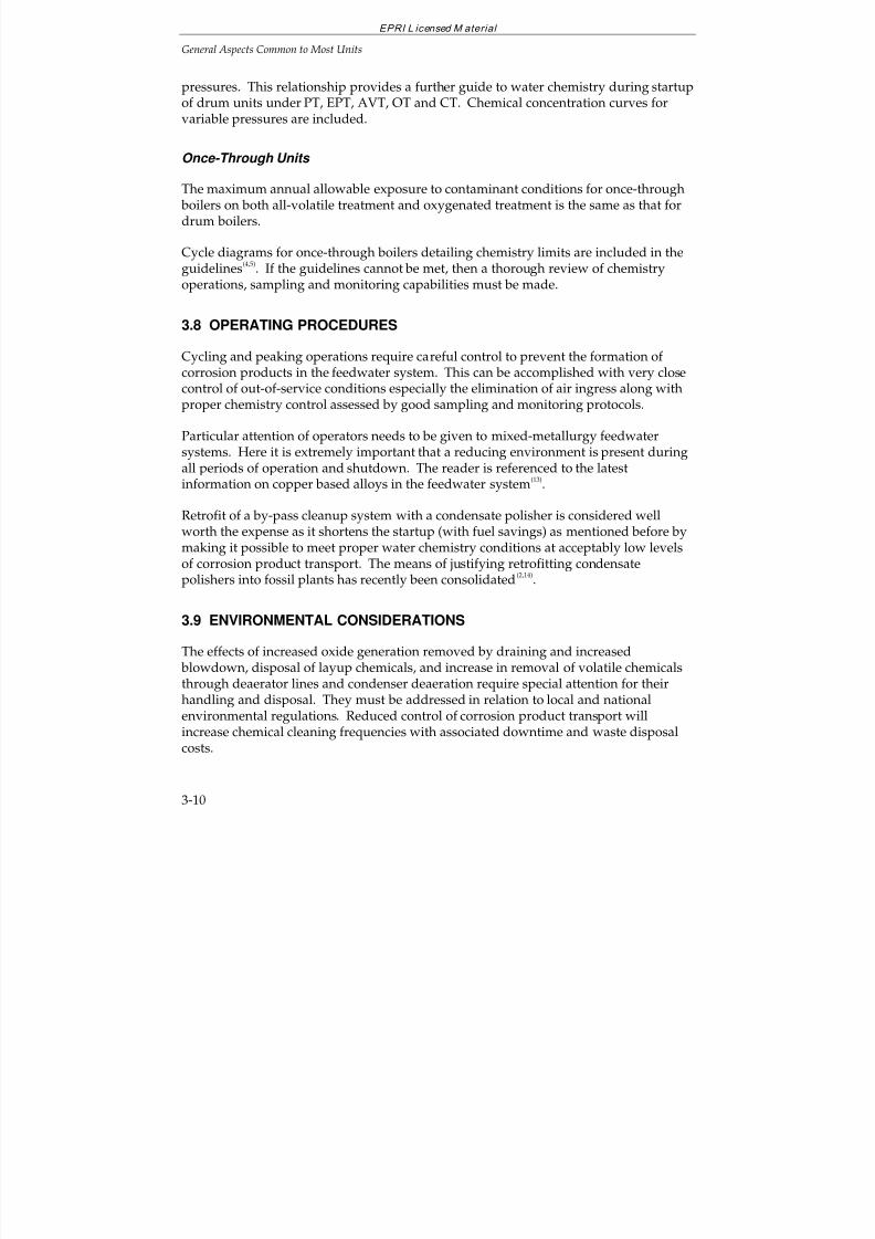
7/18/2019 EPRI Start Up, Lay Up & Shut Down Guidelines for Chemist
http://slidepdf.com/reader/full/epri-start-up-lay-up-shut-down-guidelines-for-chemist 100/256
EPRI L icensed M aterial
General Aspects Common to Most Units
3-10
pressures. This relationship provides a further guide to water chemistry during startupof drum units under PT, EPT, AVT, OT and CT. Chemical concentration curves forvariable pressures are included.
Once-Through Units
The maximum annual allowable exposure to contaminant conditions for once-through boilers on both all-volatile treatment and oxygenated treatment is the same as that fordrum boilers.
Cycle diagrams for once-through boilers detailing chemistry limits are included in theguidelines
(4,5). If the guidelines cannot be met, then a thorough review of chemistry
operations, sampling and monitoring capabilities must be made.
3.8 OPERATING PROCEDURES
Cycling and peaking operations require careful control to prevent the formation of corrosion products in the feedwater system. This can be accomplished with very closecontrol of out-of-service conditions especially the elimination of air ingress along withproper chemistry control assessed by good sampling and monitoring protocols.
Particular attention of operators needs to be given to mixed-metallurgy feedwatersystems. Here it is extremely important that a reducing environment is present duringall periods of operation and shutdown. The reader is referenced to the latestinformation on copper based alloys in the feedwater system
(13).
Retrofit of a by-pass cleanup system with a condensate polisher is considered wellworth the expense as it shortens the startup (with fuel savings) as mentioned before bymaking it possible to meet proper water chemistry conditions at acceptably low levelsof corrosion product transport. The means of justifying retrofitting condensatepolishers into fossil plants has recently been consolidated
(2,14).
3.9 ENVIRONMENTAL CONSIDERATIONS
The effects of increased oxide generation removed by draining and increased
blowdown, disposal of layup chemicals, and increase in removal of volatile chemicalsthrough deaerator lines and condenser deaeration require special attention for theirhandling and disposal. They must be addressed in relation to local and nationalenvironmental regulations. Reduced control of corrosion product transport willincrease chemical cleaning frequencies with associated downtime and waste disposalcosts.
7/18/2019 EPRI Start Up, Lay Up & Shut Down Guidelines for Chemist
http://slidepdf.com/reader/full/epri-start-up-lay-up-shut-down-guidelines-for-chemist 101/256
EPRI L icensed M aterial
General Aspects Common to Most Units
3-11
3.10 REFERENCES
1. ASME Handbook On Water Technology for Thermal Power Systems. ASME, UnitedEngineering Center, East 47
th Street, New York, NY, 10017.
(a) Chapter 22 Postoperational Treatment, Lay-up, and Flushing
(b) Chapter 13 In-Cycle Processing Principals and Equipment
2. Condensate Polishing Guidelines. TR-104422. Palo Alto, Calif.: Electric PowerResearch Institute, September 1996.
3. Cycle Chemistry Guidelines for Fossil Plants: Phosphate Treatment for Drum Units. TR-103665. Palo Alto, Calif.: Electric Power Research Institute, December 1994.
4. Cycle Chemistry Guidelines for Fossil Plants, All-Volatile Treatment. EPRI TR-105041,Final Report, April 1996.
5. Cycle Chemistry Guidelines for Fossil Plants, Oxygenated Treatment. EPRI TR-102285,Final Report, December 1994.
6. Guidelines for Make-Up Water Treatment. EPRI GS-6699, March 1990.
7. Membrane Filter Comparison Charts, available from Babcock & Wilcox - ServiceTechnology, P.O. Box 351, 20 S. Van Buren Avenue, Barberton, Ohio 44203-0351.
8. Guideline Manual on Instrumentation and Control. CS-5164. Palo Alto, Calif.: ElectricPower Research Institute, April 1987.
9. J. Brown and P. McSweeney. “Feedwater Line Corrosion”. Proceedings of the American Power Conference, Volume 39. 1977.
10. J. Brown and P. McSweeney. “Feedwater Line Corrosion”, Combustion, Volume 49,No. 2, August 1977.
11. Mathews, J. “The Importance of Start-up Chemistry to the Long-Term Reliability of Power Generating Equipment.” ASME Workshop on Improvement of ChemistryControl During Start-up of Fossil Units, St. Louis, Mo. April 9-10, 1997.
12. Sodium Hydroxide for Conditioning the Boiler Water of Drum-Type Boilers. EPRI, TR-105041, April 1996.
13. State-of-Knowledge of Copper in Fossil Plant Cycles. EPRI TR-108460, September 1997.
14. Cycle Chemistry Improvement for Fossil Power Plants. RP 2712-11, Palo Alto, Calif.:Electric Power Research Institute.

7/18/2019 EPRI Start Up, Lay Up & Shut Down Guidelines for Chemist
http://slidepdf.com/reader/full/epri-start-up-lay-up-shut-down-guidelines-for-chemist 102/256
EPRI L icensed M aterial
General Aspects Common to Most Units
3-12
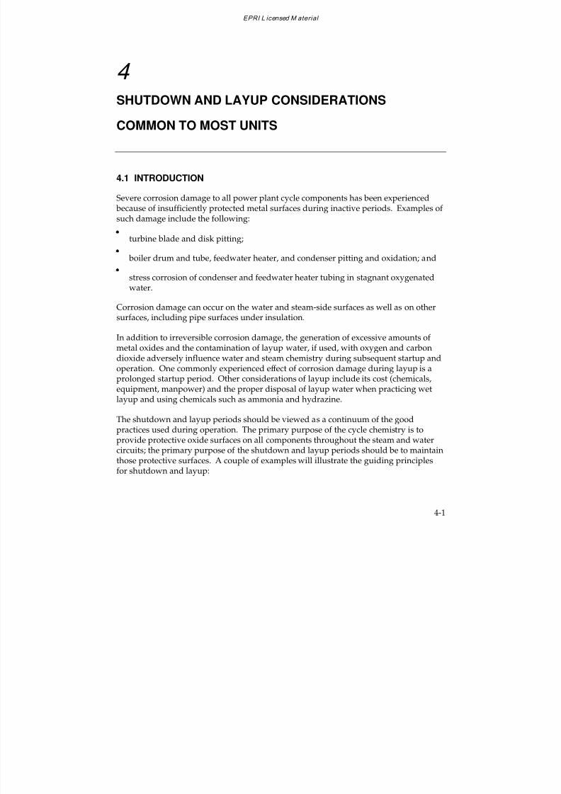
7/18/2019 EPRI Start Up, Lay Up & Shut Down Guidelines for Chemist
http://slidepdf.com/reader/full/epri-start-up-lay-up-shut-down-guidelines-for-chemist 103/256
EPRI L icensed M aterial
4-1
4
SHUTDOWN AND LAYUP CONSIDERATIONS
COMMON TO MOST UNITS
4.1 INTRODUCTION
Severe corrosion damage to all power plant cycle components has been experienced because of insufficiently protected metal surfaces during inactive periods. Examples of such damage include the following:
turbine blade and disk pitting;
boiler drum and tube, feedwater heater, and condenser pitting and oxidation; and
stress corrosion of condenser and feedwater heater tubing in stagnant oxygenatedwater.
Corrosion damage can occur on the water and steam-side surfaces as well as on other
surfaces, including pipe surfaces under insulation.
In addition to irreversible corrosion damage, the generation of excessive amounts of metal oxides and the contamination of layup water, if used, with oxygen and carbondioxide adversely influence water and steam chemistry during subsequent startup andoperation. One commonly experienced effect of corrosion damage during layup is aprolonged startup period. Other considerations of layup include its cost (chemicals,equipment, manpower) and the proper disposal of layup water when practicing wetlayup and using chemicals such as ammonia and hydrazine.
The shutdown and layup periods should be viewed as a continuum of the good
practices used during operation. The primary purpose of the cycle chemistry is toprovide protective oxide surfaces on all components throughout the steam and watercircuits; the primary purpose of the shutdown and layup periods should be to maintainthose protective surfaces. A couple of examples will illustrate the guiding principlesfor shutdown and layup:
7/18/2019 EPRI Start Up, Lay Up & Shut Down Guidelines for Chemist
http://slidepdf.com/reader/full/epri-start-up-lay-up-shut-down-guidelines-for-chemist 104/256
EPRI L icensed M aterial
Shutdown and Layup Considerations Common to Most Units
4-2
Use of OT with all-ferrous feedwater systems is to provide surfaces completelyprotected by FeOOH. Thus during shutdown and layup those surfaces should not be exposed to reducing chemistries by application of hydrazine or alternatives;
In contrast with mixed metallurgy feedwater systems, it is necessary to maintain
reducing conditions during operation so that cuprous oxide is the protective oxideof choice. Thus during shutdown and layup these surfaces should not be exposedto oxidizing chemistries.
Preventative measures for protecting steam cycle equipment during shutdown forinactive periods, including short-term and longterm layup, are presented in thissection. More specific layup considerations are found in subsequent Sections(phosphate treated units—Section 5; AVT units—Section 6; OT Units—Section 7; caustictreated units—Section 8)
4.2 LAYUP PRACTICES
The procedures for layup of idle equipment fall into two general categories: the wetand the dry procedures. In general, with the exception for units on oxygenatedtreatment (OT), wet layup requires filling of most of the system with an alkalinereducing solution (ammonia and hydrazine) and preventing air ingress bypressurization with an inert gas (nitrogen). Dry layup requires drainage while hot, andremoval of all water followed by pressurization with a moisture-free inert gas or by useof dehumidified air to maintain a low moisture environment. In selecting the properlayup procedure for a specific boiler or steam generator and its related equipment, onemust consider the following
(1):
the compatibility between the chemistry required for layup and that used duringoperation;
maintenance of the protective oxides formed during operation;
the possibility the boiler or steam generator may be required for operation on shortnotice;
facilities available for proper disposal of layup solutions;
the possibility of freezing;
a realistic assessment of the practicality of maintaining all the required conditions of a given procedure, i.e., complete dryness in dry layup or completely filled reducingconditions in wet layup (except for OT units);
local atmospheric conditions, e.g., salt air environment; and
7/18/2019 EPRI Start Up, Lay Up & Shut Down Guidelines for Chemist
http://slidepdf.com/reader/full/epri-start-up-lay-up-shut-down-guidelines-for-chemist 105/256
EPRI L icensed M aterial
Shutdown and Layup Considerations Common to Most Units
4-3
the availability of sufficient high quality condensate, deaerated demineralizedwater, nitrogen or dehumidified air during a unit outage.
A number of guidelines and other information have been published relative toshutdown and layup and are available for review
(2-7).
A comparison of the advantages and disadvantages for various shutdown and layupalternatives is given in Table 4-1
(18).
Short-term vs. Longterm Layup
Current layup practices vary widely, from the protection of all cycle componentsduring longterm layup, to providing no protection to any component. There shouldnot, however, be any difference in the degree of corrosion protection provided during ashort-term or longterm layup. The most significant differences between the two are in
the cost of layup chemicals, layup preparation, and maintenance.
For short-term layup periods, the following shutdown procedures have proveneffective:
Maintain condenser vacuum and turbine seals to protect the condensate systemfrom air ingress.
Provide auxiliary steam to blanket the deaerator. If auxiliary steam is unavailable,pegging steam from an adjacent unit or from the drum should be provided. Forlonger outages, nitrogen blanketing may be more convenient.
Nitrogen or steam blanket the boiler. The nitrogen or steam inerting systemsshould be automatic with multiple injection points on the boiler, deaerator,superheater and feedtrain vents. A unit with frequent shutdowns requires a fastresponse system, thus indicating an automatic system.
For short outages, a turbine steam bypass system will permit the boiler to operate at alow firing rate while taking the turbine off-line. This procedure may result in a netenergy savings while facilitating rapid return to service once load demand increases.Several references
(8,9) can be consulted relative to these turbine bypass systems.
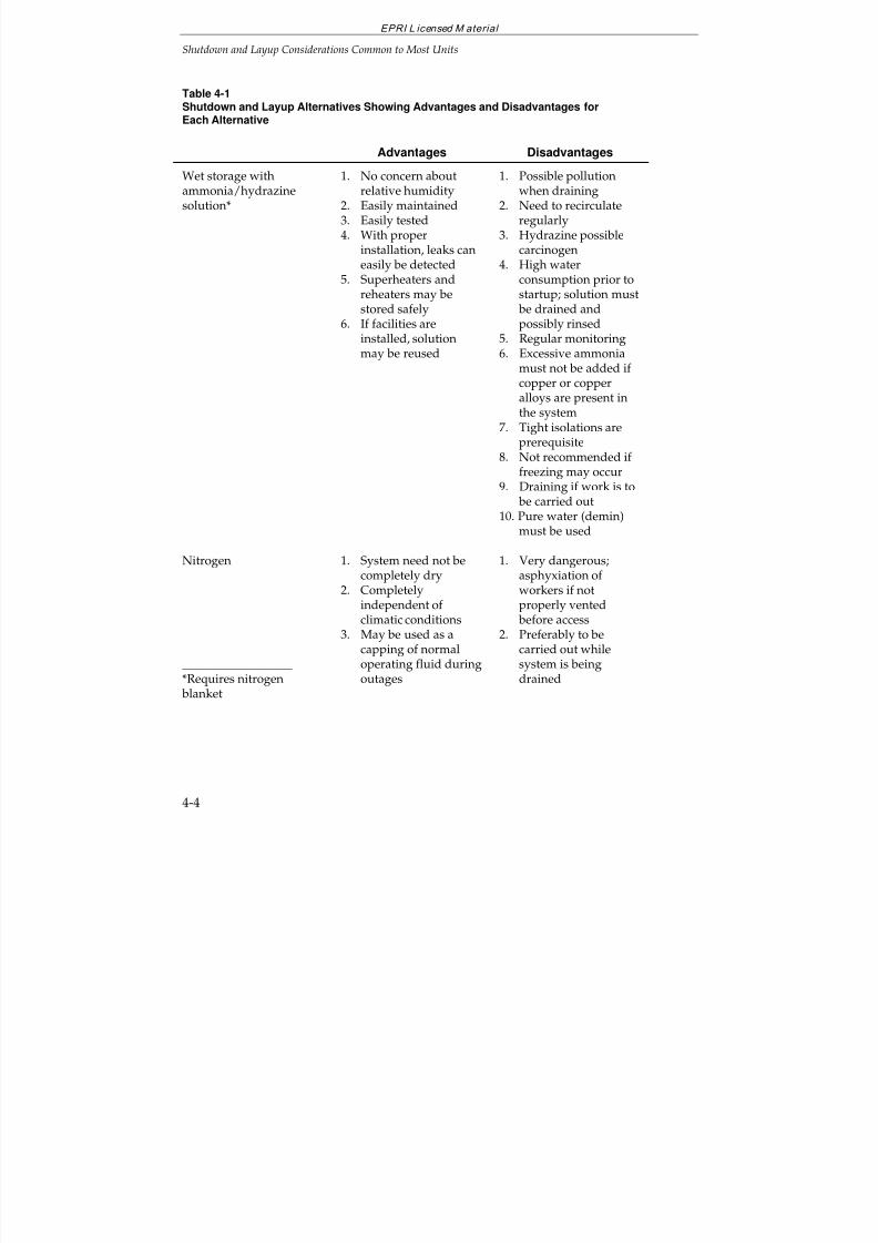
7/18/2019 EPRI Start Up, Lay Up & Shut Down Guidelines for Chemist
http://slidepdf.com/reader/full/epri-start-up-lay-up-shut-down-guidelines-for-chemist 106/256
EPRI L icensed M aterial
Shutdown and Layup Considerations Common to Most Units
4-4
Table 4-1Shutdown and Layup Alternatives Showing Advantages and Disadvantages forEach Alternative
Advantages Disadvantages
Wet storage withammonia/hydrazinesolution*
1. No concern aboutrelative humidity
2. Easily maintained3. Easily tested4. With proper
installation, leaks caneasily be detected
5. Superheaters andreheaters may bestored safely
6. If facilities are
installed, solutionmay be reused
1. Possible pollutionwhen draining
2. Need to recirculateregularly
3. Hydrazine possiblecarcinogen
4. High waterconsumption prior tostartup; solution must be drained andpossibly rinsed
5. Regular monitoring6. Excessive ammonia
must not be added if copper or copperalloys are present inthe system
7. Tight isolations areprerequisite
8. Not recommended if freezing may occur
9. Draining if work is to
be carried out10. Pure water (demin)
must be used
Nitrogen
__________________*Requires nitrogen blanket
1. System need not becompletely dry
2. Completelyindependent of climatic conditions
3. May be used as acapping of normaloperating fluid duringoutages
1. Very dangerous;asphyxiation of workers if notproperly vented before access
2. Preferably to becarried out whilesystem is beingdrained
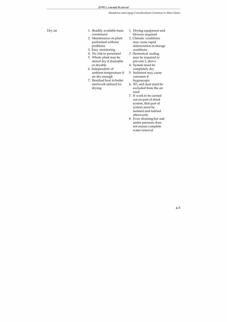
7/18/2019 EPRI Start Up, Lay Up & Shut Down Guidelines for Chemist
http://slidepdf.com/reader/full/epri-start-up-lay-up-shut-down-guidelines-for-chemist 107/256
EPRI L icensed M aterial
Shutdown and Layup Considerations Common to Most Units
4-5
Dry air 1. Readily available basicconstituent
2. Maintenance on plant
performed withoutproblems3. Easy monitoring4. No risk to personnel5. Whole plant may be
stored dry if drainableor dryable
6. Independent of ambient temperature if air dry enough
7. Residual heat in boilersteelwork utilized for
drying
1. Drying equipment and blowers required
2. Climatic conditions
may cause rapiddeterioration in storageconditions
3. Hermetical sealingmay be required toprevent 2, above
4. System must becompletely dry
5. Sediment may causecorrosion if hygroscopic
6. SO2 and dust must be
excluded from the airused
7. If work to be carriedout on part of driedsystem, that part of system must beisolated and redriedafterwards
8. Even draining hot andunder pressure doesnot ensure complete
water removal
7/18/2019 EPRI Start Up, Lay Up & Shut Down Guidelines for Chemist
http://slidepdf.com/reader/full/epri-start-up-lay-up-shut-down-guidelines-for-chemist 108/256
EPRI L icensed M aterial
Shutdown and Layup Considerations Common to Most Units
4-6
Some of the major advantages cited for turbine bypass systems are(10)
:
Flexibility of operation
Ability to hold the generator output during startup without undesirable turbine
cooling
Ability to recover following a load rejection before restarting or reloading theturbine
Ability to match turbine metal temperatures on hot restart
Some of the disadvantages cited for turbine bypass systems are:
Increased plant cost
Complexity of control
Additional valve maintenance
Possibility of turbine or condenser damage from malfunction or failure of bypasscomponents
Increase in plant heat rate because of greater condenser heat loss during periods of bypass system operation
Successful extended boiler layups have been accomplished using one of the followingoptions:
a wet layup with a pH of up to 10.0 achieved with ammonia, up to 200 ppm of hydrazine, and condensate-quality water plus a pressurized nitrogen blanket.(Note: The use of hydrazine is not recommended for units on oxygenated treatment.Refer to Section 7 for recommendations for OT units.) Lower level reducing agenttreatments (for example 5-10 ppm hydrazine) have been found to be successful andallow a quick return to service (See example in Section 4.7 and Step 6 in Section 4.8).High concentrations of ammonia should be prevented from coming into contactwith copper alloys.
a wet layup with treated good quality boiler water of the same chemicalcomposition as that used during operation; or
a dry layup in which a hot boiler is drained and purged with nitrogen ordehumidified air.
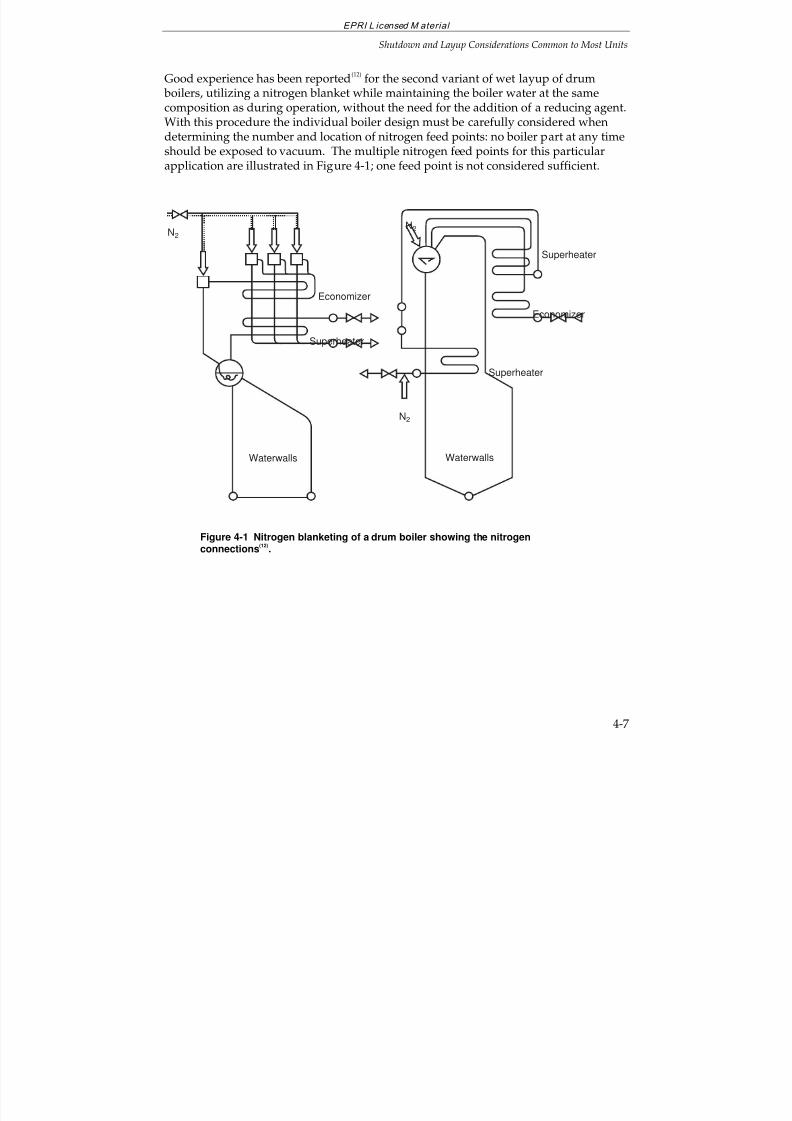
7/18/2019 EPRI Start Up, Lay Up & Shut Down Guidelines for Chemist
http://slidepdf.com/reader/full/epri-start-up-lay-up-shut-down-guidelines-for-chemist 109/256
EPRI L icensed M aterial
Shutdown and Layup Considerations Common to Most Units
4-7
Good experience has been reported(12)
for the second variant of wet layup of drum boilers, utilizing a nitrogen blanket while maintaining the boiler water at the samecomposition as during operation, without the need for the addition of a reducing agent.With this procedure the individual boiler design must be carefully considered whendetermining the number and location of nitrogen feed points: no boiler part at any time
should be exposed to vacuum. The multiple nitrogen feed points for this particularapplication are illustrated in Figure 4-1; one feed point is not considered sufficient.
Waterwalls
Economizer
Superheater
N2
Economizer
Superheater
N2
Superheater
N2
Waterwalls
Figure 4-1 Nitrogen blanketing of a drum boiler showing the nitrogenconnections
(12).
7/18/2019 EPRI Start Up, Lay Up & Shut Down Guidelines for Chemist
http://slidepdf.com/reader/full/epri-start-up-lay-up-shut-down-guidelines-for-chemist 110/256
EPRI L icensed M aterial
Shutdown and Layup Considerations Common to Most Units
4-8
4.3 WET LAYUP(12-15)
Wet layup is a popular method of “protecting” a unit when it might have to bereturned to service on relatively short notice. It generally involves filling the unit with
demineralized water containing an excess of a reducing agent (oxygen scavenger).Depending on design, the oxygen scavenger may be eliminated assuming a viablenitrogen blanketing system is available. Circulation may be maintained, a head tankmay be used, or positive nitrogen pressure may be maintained throughout theshutdown with water at normal operating levels. Wet layup can generally be used forrelatively short periods of up to 6 months although longer idle times may beexperienced.
Extensive use of nitrogen blanketing is recommended in conjunction with wet storage,not only for the boiler, but also with other heat cycle components. Excellent layupprotection has been reported using a bulk nitrogen system comprised of liquid nitrogenstorage and provided with evaporators to convert the liquid nitrogen to gas.
A nitrogen cap:
Allows boiler and feedwater equipment to remain full
Requires no excessive addition of chemicals
Permits nitrogen to rush in when steam collapses, preventing oxygen from enteringthe system.
The following procedures are utilized with a bulk nitrogen system:
Main Condenser and Turbine
Nitrogen addition starts while the turbine is still spinning down
Nitrogen is added quickly at first, then slowly as the vacuum approaches zero (Thecondenser is the largest user of nitrogen)
Deaerator and Storage Tank
Nitrogen is added when the deaerator is still hot
Nitrogen is purged for about 20 minutes followed by the maintenance of a smallnitrogen positive flow
7/18/2019 EPRI Start Up, Lay Up & Shut Down Guidelines for Chemist
http://slidepdf.com/reader/full/epri-start-up-lay-up-shut-down-guidelines-for-chemist 111/256
EPRI L icensed M aterial
Shutdown and Layup Considerations Common to Most Units
4-9
Feedwater Heaters
Nitrogen is supplied through a shell-side vent line
Steam Drum
Nitrogen enters the drum through vent lines
Nitrogen feed is started while the drum is still hot.
During wet layup, the oxygen scavenger concentration and the ORP must bemonitored. Also, the boiler and economizer waters should be circulated routinely toprevent stagnant conditions developing.
Corrosion in the form of pitting frequently occurs under wet layup conditions due topoor circulation of the treated water or failure to maintain a positive nitrogen pressure.
More serious is the fact that cracking has been found associated with welds in someunits. The cracking is the result of a corrosion fatigue mechanism similar to that foundin deaerators. The corrosion occurs during the layup period, with cracking followingsoon after startup. Cracking has occurred around nozzles, particularly in the steamdrum but has been found, to a lesser extent, on the head to shell welds as well.
The use of a nitrogen cap, as outlined above, improves startup chemistry, reduceslayup corrosion, reduces boiler tube deposits and lengthens the time between chemicalcleanings.
Because nitrogen gas does not support human life, safety issues are very important.Therefore, before any equipment that has been laid-up with nitrogen can be entered bypersonnel, all nitrogen supply lines must be disconnected, the equipment purged withair, and oxygen levels verified as safe by proper oxygen test procedures.
4.4 DRY LAYUP USING DEHUMIDIFIED AIR
The use of clean, dehumidified air to purge the boiler and auxiliary equipment duringlayup periods is routinely practiced internationally, and is gaining in popularity in theUS for both long- and short-term layup periods.
The justification for the use of dehumidified air to protect ferrous surfaces is depictedgraphically in Figure 4-2, which is a plot of corrosion rate vs. humidity of air. Thisgraph illustrates that corrosion can be mitigated by maintaining air in contact withcorrosion prone surfaces at a relative humidity of 60% or less.
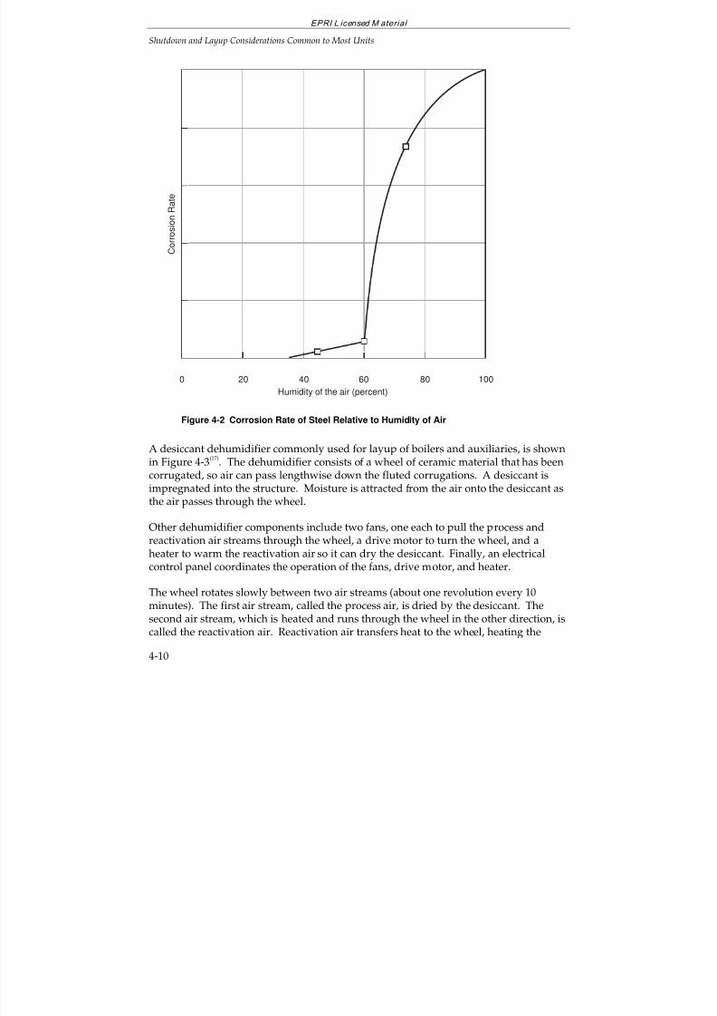
7/18/2019 EPRI Start Up, Lay Up & Shut Down Guidelines for Chemist
http://slidepdf.com/reader/full/epri-start-up-lay-up-shut-down-guidelines-for-chemist 112/256
EPRI L icensed M aterial
Shutdown and Layup Considerations Common to Most Units
4-10
Humidity of the air (percent)
80400
C o r r o s i o n R a t e
6020 100
Figure 4-2 Corrosion Rate of Steel Relative to Humidity of Air
A desiccant dehumidifier commonly used for layup of boilers and auxiliaries, is shownin Figure 4-3
(17). The dehumidifier consists of a wheel of ceramic material that has been
corrugated, so air can pass lengthwise down the fluted corrugations. A desiccant isimpregnated into the structure. Moisture is attracted from the air onto the desiccant asthe air passes through the wheel.
Other dehumidifier components include two fans, one each to pull the process andreactivation air streams through the wheel, a drive motor to turn the wheel, and a
heater to warm the reactivation air so it can dry the desiccant. Finally, an electricalcontrol panel coordinates the operation of the fans, drive motor, and heater.
The wheel rotates slowly between two air streams (about one revolution every 10minutes). The first air stream, called the process air, is dried by the desiccant. Thesecond air stream, which is heated and runs through the wheel in the other direction, iscalled the reactivation air. Reactivation air transfers heat to the wheel, heating the
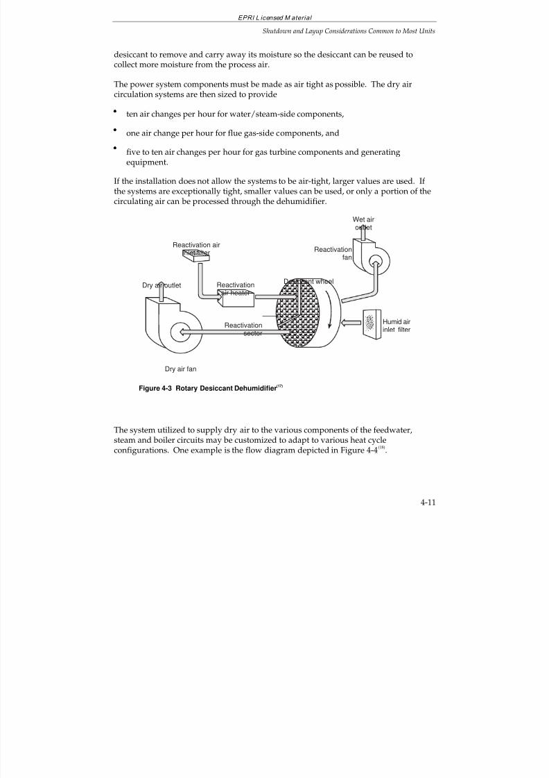
7/18/2019 EPRI Start Up, Lay Up & Shut Down Guidelines for Chemist
http://slidepdf.com/reader/full/epri-start-up-lay-up-shut-down-guidelines-for-chemist 113/256
EPRI L icensed M aterial
Shutdown and Layup Considerations Common to Most Units
4-11
desiccant to remove and carry away its moisture so the desiccant can be reused tocollect more moisture from the process air.
The power system components must be made as air tight as possible. The dry aircirculation systems are then sized to provide
ten air changes per hour for water/steam-side components,
one air change per hour for flue gas-side components, and
five to ten air changes per hour for gas turbine components and generatingequipment.
If the installation does not allow the systems to be air-tight, larger values are used. If the systems are exceptionally tight, smaller values can be used, or only a portion of thecirculating air can be processed through the dehumidifier.
Dry air outlet
Reactivation airinlet filter
Reactivationair heater
Dry air fan
Desiccant wheel
Wet airoutlet
Reactivationfan
Reactivationsector
Humid airinlet filter
Figure 4-3 Rotary Desiccant Dehumidifier(17)
The system utilized to supply dry air to the various components of the feedwater,steam and boiler circuits may be customized to adapt to various heat cycleconfigurations. One example is the flow diagram depicted in Figure 4-4
(18).
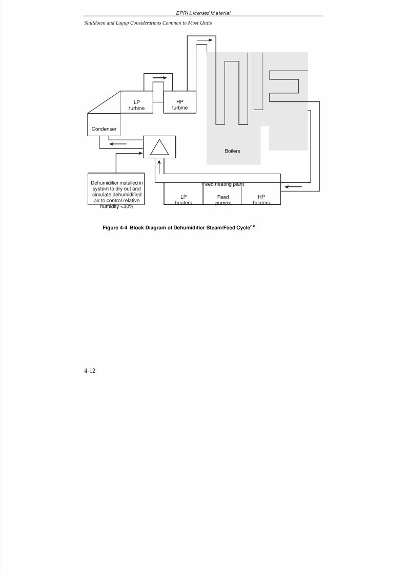
7/18/2019 EPRI Start Up, Lay Up & Shut Down Guidelines for Chemist
http://slidepdf.com/reader/full/epri-start-up-lay-up-shut-down-guidelines-for-chemist 114/256
EPRI L icensed M aterial
Shutdown and Layup Considerations Common to Most Units
4-12
Boilers
Feed heating plant
LPheaters
Feedpumps
HPheaters
Dehumidifier installed insystem to dry out andcirculate dehumidifiedair to control relative
humidity <30%
Condenser
LPturbine
HPturbine
Figure 4-4 Block Diagram of Dehumidifier Steam/Feed Cycle(18)
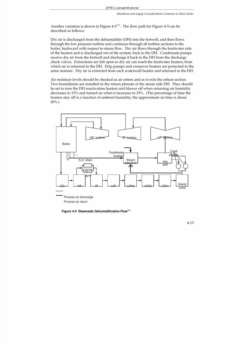
7/18/2019 EPRI Start Up, Lay Up & Shut Down Guidelines for Chemist
http://slidepdf.com/reader/full/epri-start-up-lay-up-shut-down-guidelines-for-chemist 115/256
EPRI L icensed M aterial
Shutdown and Layup Considerations Common to Most Units
4-13
Another variation is shown in Figure 4-5(19)
. The flow path for Figure 4-5 can bedescribed as follows:
Dry air is discharged from the dehumidifier (DH) into the hotwell, and then flowsthrough the low pressure turbine and continues through all turbine sections to the boiler, backward with respect to steam flow. Dry air flows through the feedwater sideof the heaters and is discharged out of the system, back to the DH. Condensate pumpsreceive dry air from the hotwell and discharge it back to the DH from the dischargecheck valves. Extractions are left open so dry air can reach the feedwater heaters, fromwhich air is returned to the DH. Drip pumps and crossover heaters are protected in thesame manner. Dry air is extracted from each waterwall header and returned to the DH.
Air moisture levels should be checked as air enters and as it exits the reheat section.Two humidistats are installed in the return plenum of the steam side DH. They should be set to turn the DH reactivation heaters and blower off when returning air humidity
decreases to 15% and turned on when it increases to 25%. (The percentage of time theheaters stay off is a function of ambient humidity; the approximate on time is about40%.)
Condpumps
XO HP IP
BFP
LP#3 LP#2 LP#1
Gland
cond
BFP
LIP
Boiler
Hotwell
HP turbine IP turbine LP turbine
Steamside D.H.
unit
S.H. drain
Feedwaterheaters
Process air discharge
Process air return
Figure 4-5 Steamside Dehumidification Flow(19)
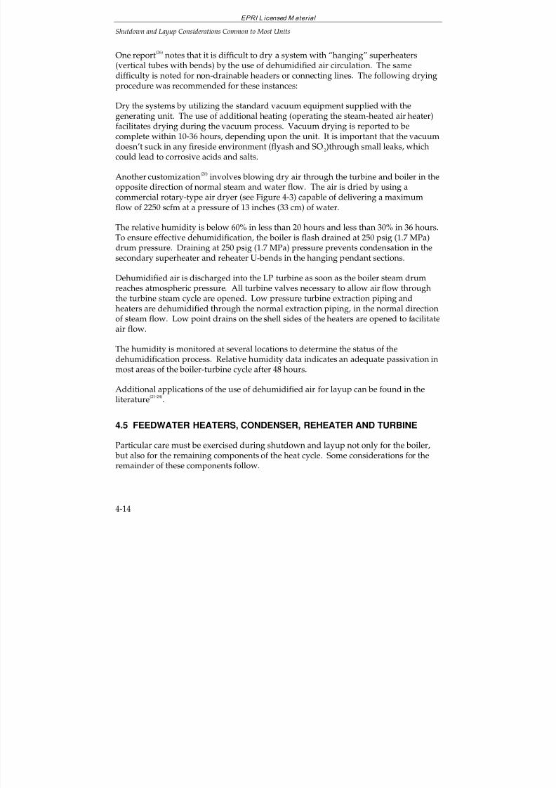
7/18/2019 EPRI Start Up, Lay Up & Shut Down Guidelines for Chemist
http://slidepdf.com/reader/full/epri-start-up-lay-up-shut-down-guidelines-for-chemist 116/256
EPRI L icensed M aterial
Shutdown and Layup Considerations Common to Most Units
4-14
One report(26)
notes that it is difficult to dry a system with “hanging” superheaters(vertical tubes with bends) by the use of dehumidified air circulation. The samedifficulty is noted for non-drainable headers or connecting lines. The following dryingprocedure was recommended for these instances:
Dry the systems by utilizing the standard vacuum equipment supplied with thegenerating unit. The use of additional heating (operating the steam-heated air heater)facilitates drying during the vacuum process. Vacuum drying is reported to becomplete within 10-36 hours, depending upon the unit. It is important that the vacuumdoesn’t suck in any fireside environment (flyash and SO2)through small leaks, whichcould lead to corrosive acids and salts.
Another customization(20)
involves blowing dry air through the turbine and boiler in theopposite direction of normal steam and water flow. The air is dried by using acommercial rotary-type air dryer (see Figure 4-3) capable of delivering a maximumflow of 2250 scfm at a pressure of 13 inches (33 cm) of water.
The relative humidity is below 60% in less than 20 hours and less than 30% in 36 hours.To ensure effective dehumidification, the boiler is flash drained at 250 psig (1.7 MPa)drum pressure. Draining at 250 psig (1.7 MPa) pressure prevents condensation in thesecondary superheater and reheater U-bends in the hanging pendant sections.
Dehumidified air is discharged into the LP turbine as soon as the boiler steam drumreaches atmospheric pressure. All turbine valves necessary to allow air flow throughthe turbine steam cycle are opened. Low pressure turbine extraction piping andheaters are dehumidified through the normal extraction piping, in the normal direction
of steam flow. Low point drains on the shell sides of the heaters are opened to facilitateair flow.
The humidity is monitored at several locations to determine the status of thedehumidification process. Relative humidity data indicates an adequate passivation inmost areas of the boiler-turbine cycle after 48 hours.
Additional applications of the use of dehumidified air for layup can be found in theliterature
(21-24).
4.5 FEEDWATER HEATERS, CONDENSER, REHEATER AND TURBINE
Particular care must be exercised during shutdown and layup not only for the boiler, but also for the remaining components of the heat cycle. Some considerations for theremainder of these components follow.
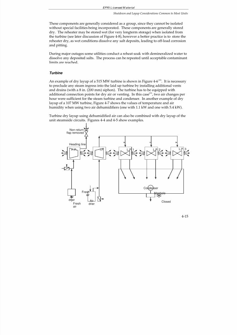
7/18/2019 EPRI Start Up, Lay Up & Shut Down Guidelines for Chemist
http://slidepdf.com/reader/full/epri-start-up-lay-up-shut-down-guidelines-for-chemist 117/256
EPRI L icensed M aterial
Shutdown and Layup Considerations Common to Most Units
4-15
These components are generally considered as a group, since they cannot be isolatedwithout special facilities being incorporated. These components are generally storeddry. The reheater may be stored wet (for very longterm storage) when isolated fromthe turbine (see later discussion of Figure 4-8), however a better practice is to store thereheater dry, as wet conditions dissolve any salt deposits, leading to off-load corrosion
and pitting.
During major outages some utilities conduct a reheat soak with demineralized water todissolve any deposited salts. The process can be repeated until acceptable contaminantlimits are reached.
Turbine
An example of dry layup of a 515 MW turbine is shown in Figure 4-6(23)
. It is necessaryto preclude any steam ingress into the laid up turbine by installing additional vents
and drains (with a 8 in. (200 mm) siphon). The turbine has to be equipped withadditional connection points for dry air or venting. In this case
(23), two air changes per
hour were sufficient for the steam turbine and condenser. In another example of drylayup of a 107 MW turbine, Figure 4-7 shows the values of temperature and airhumidity when using two air dehumidifiers (one with 1.1 kW and one with 5.4 kW).
Turbine dry layup using dehumidified air can also be combined with dry layup of theunit steamside circuits. Figures 4-4 and 4-5 show examples.
H.P. I.P. L.P. 1 L.P. 2 L.P. 3
Condenser
ClosedFreshair
Freshair
Airdrier Air
drier
Non-returnflap removed
Heading line
Manhole
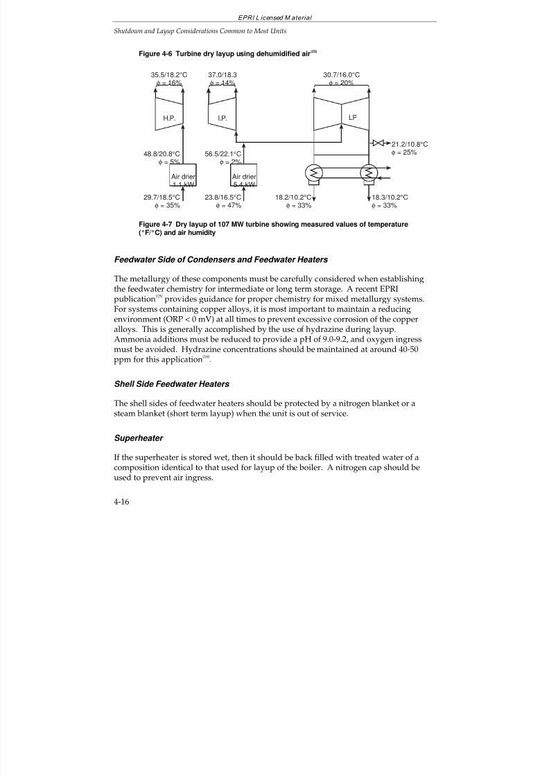
7/18/2019 EPRI Start Up, Lay Up & Shut Down Guidelines for Chemist
http://slidepdf.com/reader/full/epri-start-up-lay-up-shut-down-guidelines-for-chemist 118/256
EPRI L icensed M aterial
Shutdown and Layup Considerations Common to Most Units
4-16
Figure 4-6 Turbine dry layup using dehumidified air(23)
35.5/18.2°Cφ = 16%
I.P. LP
37.0/18.3φ = 14%
30.7/16.0°Cφ = 20%
Air drier1.1 kW
29.7/18.5°Cφ = 35%
48.8/20.8°Cφ = 5%
Air drier5.4 kW
23.8/16.5°Cφ = 47%
56.5/22.1°Cφ = 2%
18.2/10.2°Cφ = 33%
18.3/10.2°Cφ = 33%
21.2/10.8°Cφ = 25%
H.P.
Figure 4-7 Dry layup of 107 MW turbine showing measured values of temperature(°F/°C) and air humidity
Feedwater Side of Condensers and Feedwater Heaters
The metallurgy of these components must be carefully considered when establishingthe feedwater chemistry for intermediate or long term storage. A recent EPRIpublication
(15) provides guidance for proper chemistry for mixed metallurgy systems.
For systems containing copper alloys, it is most important to maintain a reducingenvironment (ORP < 0 mV) at all times to prevent excessive corrosion of the copperalloys. This is generally accomplished by the use of hydrazine during layup.Ammonia additions must be reduced to provide a pH of 9.0-9.2, and oxygen ingressmust be avoided. Hydrazine concentrations should be maintained at around 40-50ppm for this application
(16).
Shell Side Feedwater Heaters
The shell sides of feedwater heaters should be protected by a nitrogen blanket or asteam blanket (short term layup) when the unit is out of service.
Superheater
If the superheater is stored wet, then it should be back filled with treated water of acomposition identical to that used for layup of the boiler. A nitrogen cap should beused to prevent air ingress.
7/18/2019 EPRI Start Up, Lay Up & Shut Down Guidelines for Chemist
http://slidepdf.com/reader/full/epri-start-up-lay-up-shut-down-guidelines-for-chemist 119/256
EPRI L icensed M aterial
Shutdown and Layup Considerations Common to Most Units
4-17
Deaerator and Storage Tank
The deaerator and deaerator storage tank should be protected by a steady, smallnitrogen purge.
4.6 LAYUP MONITORING
All layup conditions, dry or wet, should be either continuously or periodicallymonitored to ensure that the layup water or air quality is maintained. Existing samplepoints may be used to draw water samples for chemical analysis. Should the layup andwater chemistry deteriorate to corrosive conditions in a particular component, thatcomponent should be drained and refilled with properly conditioned water, oradditional chemicals added, assuming proper mixing can be provided.
4.7 ENVIRONMENTAL CONSIDERATIONS
The disposal of layup solutions containing high concentrations of alkaline chemicalssuch as ammonia, and/or high concentrations of reducing agents, such as hydrazine orhydrazine substitutes, poses problems from an environmental standpoint. Solutions tothese problems may require modifications to existing waste treatment facilities. Thecooperation of regulatory authorities should be a part of the investigative processnecessary to resolve these environmental issues.
A low level chemical layup procedure(25)
has been used to protect the environment bynot requiring draining of drum boilers prior to startup. This has been possible through
the use of adequate layup monitoring and an efficient nitrogen blanketing system. Theprocedure is as follows:
With the boiler off-line, inject an oxygen scavenger at 5-10 ppm hydrazine equivalentinto the boiler when the boiler pressure decays to 200 psi (1.4 MPa) (typically 3 days).The chemical injection is made using the normal chemical feed system. Natural boilercirculation at 200 psi (1.4 MPa) is sufficient to mix adequately the chemicals with the boiler water.
When the boiler decays to 5 psi (0.03 MPa) pressure (typically 7 days) a nitrogen cap isapplied to the boiler.
Upon return to service, the boiler is fired, without draining the layup solution, and thedrum vents are opened until 25 psi (0.2 MPa) is reached to remove excess ammoniafrom the system.
Since it typically takes 3 days before the pressure decays to 200 psi (1.4 MPa), weekendoutages normally do not require a chemical injection treatment.
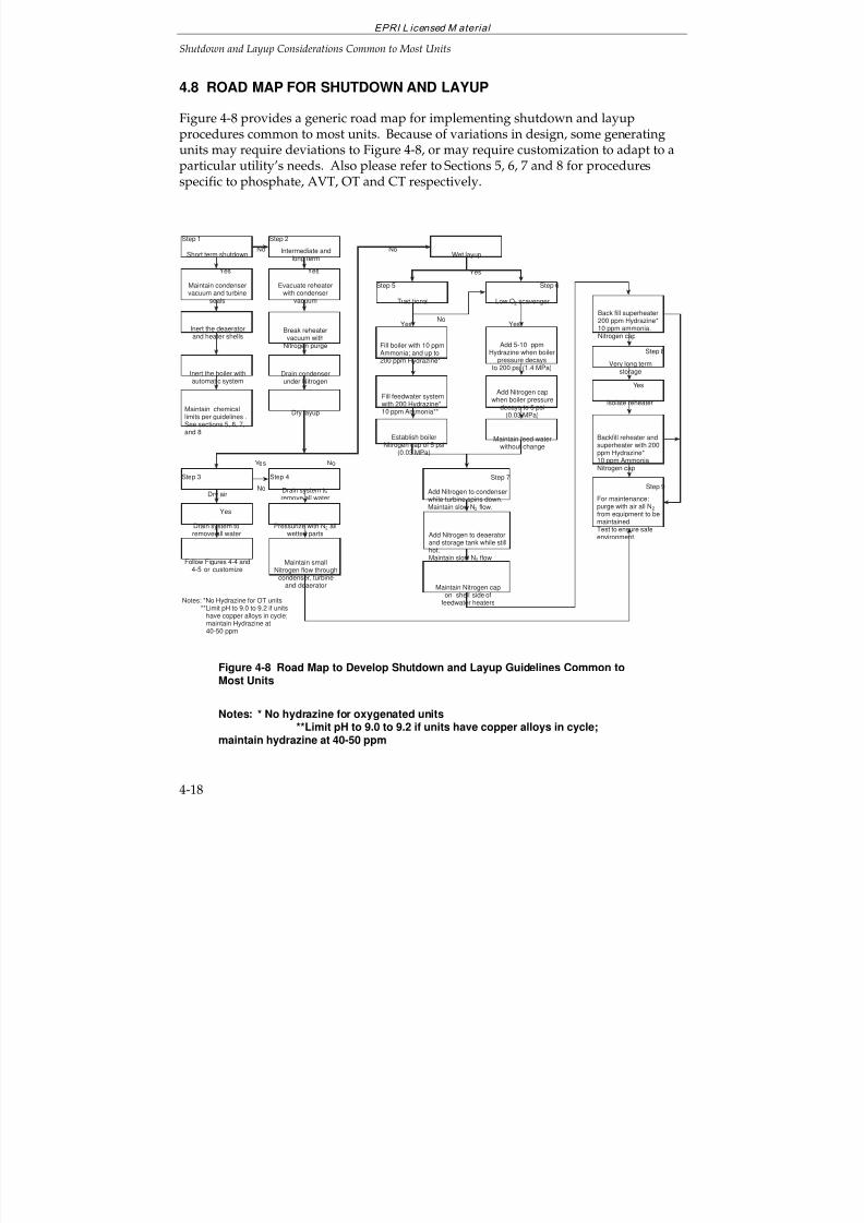
7/18/2019 EPRI Start Up, Lay Up & Shut Down Guidelines for Chemist
http://slidepdf.com/reader/full/epri-start-up-lay-up-shut-down-guidelines-for-chemist 120/256
EPRI L icensed M aterial
Shutdown and Layup Considerations Common to Most Units
4-18
4.8 ROAD MAP FOR SHUTDOWN AND LAYUP
Figure 4-8 provides a generic road map for implementing shutdown and layupprocedures common to most units. Because of variations in design, some generatingunits may require deviations to Figure 4-8, or may require customization to adapt to a
particular utility’s needs. Also please refer to Sections 5, 6, 7 and 8 for proceduresspecific to phosphate, AVT, OT and CT respectively.
Fill feedwater systemwith 200 Hydrazine*10 ppm Ammonia**
Fill boiler with 10 ppmAmmonia; and up to200 ppm Hydrazine*
Maintain feed waterwithout change
Add Nitrogen capwhen boiler pressure
decays to 5 psi(0.03 MPa)
Add 5-10 ppmHydrazine when boiler
pressure decaysto 200 psi (1.4 MPa)
Back fill superheater200 ppm Hydrazine*
10 ppm ammonia.Nitrogen cap
Wet layup
Traditional Low O2 scavenger
Add Nitrogen to deaeratorand storage tank while stillhot.Maintain slow N2 flow
Add Nitrogen to condenserwhile turbine spins down.Maintain slow N2 flow.
Maintain Nitrogen capon shell side of
feedwater heaters
Very long termstorage
Isolate reheater
Backfill reheater andsuperheater with 200ppm Hydrazine*10 ppm AmmoniaNitrogen cap
For maintenance:purge with air all N2
from equipment to bemaintained.Test to ensure safeenvironment.
Short term shutdown
Maintain condenservacuum and turbine
seals
Inert the deaeratorand heater shells
Inert the boiler withautomatic system
Maintain chemicallimits per guidelines .See sections 5, 6, 7,and 8
Evacuate reheaterwith condenser
vacuum
Break reheatervacuum with
Nitrogen purge
Drain condenserunder Nitrogen
Intermediate andlong term
Dry layup
Dry air
Drain system toremove all water
Follow Figures 4-4 and4-5 or customize
Maintain smallNitrogen flow through
condenser, turbineand deaerator
Pressurize with N2 allwetted parts
Drain system to
remove all water
Yes
Step 8
Step 9
Step 7
Step 6
Step 2
YesNo
Yes
Yes
NoNo
Yes
Yes No
Yes
Step 3 Step 4
Step 1
Notes: *No Hydrazine for OT units**Limit pH to 9.0 to 9.2 if units
have copper alloys in cycle;maintain Hydrazine at40-50 ppm
Yes
Step 5
No
Establish boilerNitrogen cap of 5 psi
(0.03 MPa)
Figure 4-8 Road Map to Develop Shutdown and Layup Guidelines Common toMost Units
Notes: * No hydrazine for oxygenated units**Limit pH to 9.0 to 9.2 if units have copper alloys in cycle;
maintain hydrazine at 40-50 ppm
7/18/2019 EPRI Start Up, Lay Up & Shut Down Guidelines for Chemist
http://slidepdf.com/reader/full/epri-start-up-lay-up-shut-down-guidelines-for-chemist 121/256
EPRI L icensed M aterial
Shutdown and Layup Considerations Common to Most Units
4-19
Figure 4-8 is divided into 9 considerations, options or steps, which are furtherdescribed as follows:
Step 1—Short-Term Layup
Short-term layup presumes that the unit will be required to operate within a relativelyshort timeframe. In consideration of this, no major changes are required from normaloperating conditions, with the exception being that the unit must be protected from airingress. The condenser vacuum and turbine seals are maintained; the deaerator, heatershells and boiler are inerted with nitrogen or steam; and, the feedwater chemistry ismaintained according to the requirements of the treatment philosophy employed (seephosphate treatment—Section 5; AVT—Section 6; oxygenated treatment—Section 7;and caustic treatment—Section 8).
Step 2—Intermediate and Longterm Layup Common to Dry and Wet Layup
Intermediate and longterm layup require additional steps to be taken to preventcorrosion during intermediate periods of layup, such as for maintenance andindeterminate cycling or peaking requirements; and during longterm layup forindefinite periods of time. Certain procedures are common regardless of whether theunits are to be laid up dry or wet. There is a danger of off-load corrosion (pitting) if there are salts present. Consideration needs to be given to whether the reheatersupports can take the weight if the reheater is to be filled with water.
During shutdown, the turbine, condenser (steam side) and reheater are generallyconsidered together because, unless special facilities are incorporated, there is no
practical way to isolate them. With special facilities incorporated, the reheater can beisolated from the turbine and may be stored wet (see Step 8). The turbine, however,can only be laid up dry as indicated previously in this section. The condenser may beflooded and laid up wet, but several factors limit the feasibility of this procedure
(10):
The condenser must be supported from the bottom to handle the extra weight of aflooded condenser.
The expansion joints between the turbine and condenser are not designed tosupport the weight of a flooded condenser.
A flooded condenser tends to pull the turbine bearings out of alignment.
Water in the condenser may cause moisture vapor to enter the turbine causingcorrosion.
For these reasons, the steam side of the condenser is normally laid up dry.
7/18/2019 EPRI Start Up, Lay Up & Shut Down Guidelines for Chemist
http://slidepdf.com/reader/full/epri-start-up-lay-up-shut-down-guidelines-for-chemist 122/256
EPRI L icensed M aterial
Shutdown and Layup Considerations Common to Most Units
4-20
For Step 2, during shutdown, the reheater is evacuated by utilizing the vacuum in thecondenser. The vacuum is then broken using nitrogen pressure. The condenser isdrained under nitrogen.
If the turbine steam is supplied from a header system, all valves must be tight to
prevent moisture entrance into the turbine.
Step 3—Dry Air Layup
The dry air layup procedure requires that all components of the system be drained.There are several methods of maintaining dry air flow through the equipment, andsome of these are illustrated in Figures 4-4 and 4-7. The advantages and disadvantagesof dry air layup and the equipment required have been previously described in thisSection (Table 4-1).
Step 4—Dry Layup with Nitrogen
Nitrogen can be used for blanketing equipment, which is drained but not completelydry, or for blanketing equipment either filled with water or not, to prevent air ingress.
Step 4 is similar to Step 3, except nitrogen is used for a positive pressure on allcomponents rather than a dry air purge. A small continuous purge of nitrogen isrequired, however, to protect the turbine, deaerator and deaerator storage tank.
Step 5—Wet Layup: Traditional Method (Boiler and Feedwater Heaters)
The traditional method of wet layup involves filling the boiler, feedwater cycle andsuperheater with demineralized water containing a volatile alkaline, reducing solution.Up to 10 ppm of ammonia and up to 200 ppm of hydrazine have been used for thispurpose. However, for units on oxygenated treatment, hydrazine should beeliminated.
For those units having copper alloy condenser tubes and/or feedwater heaters,feedwater pH should be limited to 9.0 to 9.2 by reducing ammonia. Hydrazine is heldat 40-50 ppm. For these units, it is most important to maintain reducing conditions(ORP < 0 mV) to prevent increased attack of the copper alloys associated with a changeof the surface oxide layers from cuprous to cupric oxide.
(15).
A nitrogen cap of 5 psi (0.03 MPa) is maintained on the boiler.
Step 6—Wet Layup: Low Oxygen Scavenger Method (Boiler and Feedwater Heaters)
Many alternatives to the traditional wet layup method have been used successfully bymarkedly reducing the level of hydrazine. These procedures may not require boiler
7/18/2019 EPRI Start Up, Lay Up & Shut Down Guidelines for Chemist
http://slidepdf.com/reader/full/epri-start-up-lay-up-shut-down-guidelines-for-chemist 123/256
EPRI L icensed M aterial
Shutdown and Layup Considerations Common to Most Units
4-21
draining prior to startup, thereby protecting the environment and not requiring specialdisposal techniques or permits. In one procedure, 5 to 10 ppm of hydrazine equivalentis injected into the boiler when the boiler pressure decays to 200 psi (1.4 MPa) (typically3 days). The chemical injection is made using the normal chemical feed system.Natural boiler circulation at 200 psi (1.4 MPa) is sufficient to mix adequately the
chemicals in the boiler water. No other changes need be made to the boiler or to thefeedwater chemistry. When the boiler pressure decays to 5 psi (0.03 MPa) (typically 7days) a nitrogen cap is applied to the boiler.
Upon return to service, the boiler may be fired without draining the layup solution.Also, since it typically takes 3 days before the boiler pressure decays to 200 psi (1.4MPa), weekend outages normally do not require a chemical injection treatment.
Step 7—Wet Layup (Balance of Cycle)
As the turbine spins down, nitrogen is added to the condenser, which also purges thereheater system. A continuous purge of nitrogen is necessary to account for leakagethrough the turbine steam seals.
Nitrogen is added to the deaerator and storage tank while this system is still hot. Asmall flow of nitrogen is provided to purge this system.
A nitrogen cap is maintained on the shell side of the feedwater heaters. Thesuperheater is back filled with a solution of up to 200 ppm of hydrazine and 10 ppmammonia and a nitrogen cap maintained. (Units on oxygenated treatment willeliminate the use of hydrazine for this application.)
Step 8—Very Long Storage
For very long storage periods, the reheater is isolated from the turbine, and back filledwith a solution of up to 200 ppm hydrazine and 10 ppm ammonia, and capped withnitrogen. The superheater is treated similarly.
Step 9—Maintenance
Only equipment requiring maintenance should be drained (wet storage only), andnitrogen (if used) purged with air to provide an environment suitable for entry of
personnel. Since nitrogen does not support human life, it is extremely important thatnitrogen is completely displaced by air. The atmosphere within the equipment to bemaintained should be tested with suitable test equipment to ensure the equipment issafe for personnel entry.
7/18/2019 EPRI Start Up, Lay Up & Shut Down Guidelines for Chemist
http://slidepdf.com/reader/full/epri-start-up-lay-up-shut-down-guidelines-for-chemist 124/256
EPRI L icensed M aterial
Shutdown and Layup Considerations Common to Most Units
4-22
4.9 REFERENCES
1. The ASME Handbook on Water Technology for Thermal Power Systems. AmericanSociety of Mechanical Engineers, New York, N.Y. 1989.
2. VGB Guidelines. “Preservation of Power Plant Systems.” VGB-R116H. VGBTechnische Vereiniging der Grosskraftwerksbetreiber, 1981.
3. EPRI Guidelines. Long-Term Layup of Fossil Plants. CS-5112. Palo Alto, Calif.:Electric Power Research Institute, April 1987.
4. CEGB: “Long Term Storage of Power Plants.” General Considerations andPreservation Techniques. April 1978.
5. “Guidelines for the Long-Term Storage of Power Plants. ESKOM. Ref. NWG7021.
August 1991.
6. Monitoring Cycle Water Chemistry in Fossil Plants, GS-7556, Volume 2. Palo Alto,Calif.: Electric Power Research Institute, October 1991.
7. Cycle Chemistry Improvement for Fossil Power Plants. Electric Power ResearchInstitute, Palo Alto, Calif.: TR-104422, September 1996.
8. D. D. Rosard and T. McCloskey. “Bypass Systems Increase Cycling Capability of Drum Boilers”, Power, July, 1984.
9. J. Reasons. “Steam Bypass Systems for Drum Boilers. How Much Capacity Do YouNeed”, Power, July, 1984.
10. D. B. DeWitt-Dick. “Protection of Utility Steam Generating Systems During IdlePeriods”, A.S.M.E. Workshop “Improvement of Chemistry Control During Startupof Fossil Units”, April 9
th and 10
th, 1997, St. Louis, Missouri.
11. “Combustion Fossil Power”, J. Singer, Editor. Published by CombustionEngineering, Inc./ASEA Brown Boveri, 1991.
12. A. Bursik and R. Richter. “Hints for the Steam Generator Layup Practice” (inGerman). VGB Kraftwerkstechnik Vol. 60, No. 9, pp. 714-718.
13. R. J. Twigg. “Mothballing—The Impossible Solution?” Fossil Plant Layup andReactivation Conference. EPRI TR-101250, October 1992.
7/18/2019 EPRI Start Up, Lay Up & Shut Down Guidelines for Chemist
http://slidepdf.com/reader/full/epri-start-up-lay-up-shut-down-guidelines-for-chemist 125/256
EPRI L icensed M aterial
Shutdown and Layup Considerations Common to Most Units
4-23
14. W. Turowski and D. Daniels. “Routine Use of Nitrogen Caps”, A.S.M.E. Workshop“Improvement of Chemistry Control During Startup of Fossil Units”, April 9
th and
10th, 1997, St. Louis, Missouri.
15. State-of-Knowledge of Copper in Fossil Plant Cycles. TR-108460, Palo Alto, CA: Electric
Power Research Institute, September 1997.
16. S. R. Pate and R. C. Turner. “Minimizing Corrosion Product Transport at GeorgiaPower.” ASME Workshop, St. Louis, MO, Apr. 9-10, 1997.
17. D. Kosar. “Power Plant Preservation Using Desiccant Dehumidifiers.” Fossil PlantLayup and Reactivation Conference. EPRI TR-101250, October 1992.
18. J. Jenkins and T. Moss. “The Storex Project.” Fossil Plant Layup and ReactivationConference. EPRI TR-101250, October 1992.
19. D. B. Griffin and H. D. Thomas. “Fossil Plant Layup and UnanticipatedReactivation.” Fossil Plant Layup and Reactivation Conference. EPRI TR-101250,October 1992.
20. M. E. Walker. “Passivation of Unit 3 State Line Station Through Dehumidification.”Fossil Plant Layup and Reactivation Conference. EPRI TR-101250, October 1992.
21. T. Gostenkors. “Layup of Units in Power Station Gersteinwerk” (in German). Der Maschinenschaden, Vol. 49, No. 6, p. 236ff, 1976.
22. W. Kahlert, “Fast Startup Procedure for Standby Units in the VEW Power Station
Gersteinwerk” (in German). VGB Kraftwerkstechnik, Vol. 52, No. 5, p. 425ff, 1972.
23. H. Steger. “Standby Corrosion Prevention in Power Plants” (in German). Der Maschinenschaden, Vol. 49, No. 1, pp. 23-27, 1976.
24. T. H. Pike. “Corrosion Prevention of Turbines During Extended Outages (CaseHistories.” Proceedings of the 48th International Water Conference, Pittsburgh, PA, No.2-4, 1987.
25. W. H. Stroman and N. L. Rentle. “Declining Pressure Method for Boiler Storageand Boiler Cleanliness Assessment by Ultrasonic Technique at San Diego Gas andElectric’s South Bay Unit 4”, Fossil Operations and Maintenance InformationServices, Clearwater Beach, Florida, June 15-18, 1992.
26. VGB Guidelines, “Layup of Power Plants”, VGB-R116H, VGB KraftwerkstechnikGmbH, Essen, 1983.

7/18/2019 EPRI Start Up, Lay Up & Shut Down Guidelines for Chemist
http://slidepdf.com/reader/full/epri-start-up-lay-up-shut-down-guidelines-for-chemist 126/256
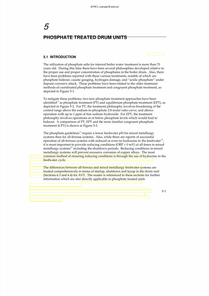
7/18/2019 EPRI Start Up, Lay Up & Shut Down Guidelines for Chemist
http://slidepdf.com/reader/full/epri-start-up-lay-up-shut-down-guidelines-for-chemist 127/256
EPRI L icensed M aterial
5-1
5
PHOSPHATE TREATED DRUM UNITS
5.1 INTRODUCTION
The utilization of phosphate salts for internal boiler water treatment is more than 70years old. During this time there have been several philosophies developed relative tothe proper use and proper concentration of phosphates in the boiler drum. Also, therehave been problems reported with these various treatments, notable of which are
phosphate hideout, caustic gouging, hydrogen damage, and “acidic phosphate” underdeposit corrosive attack. These problems have been related to the older treatmentmethods of coordinated phosphate treatment and congruent phosphate treatment, asdepicted in Figure 5-1.
To mitigate these problems, two new phosphate treatment approaches have beenidentified
(1) as phosphate treatment (PT) and equilibrium phosphate treatment (EPT), as
depicted in Figure 5-2. For PT, the treatment philosophy involves broadening of thecontrol range above the sodium-to-phosphate 2.8 molar ratio curve, and allowsoperation with up to 1 ppm of free sodium hydroxide. For EPT, the treatmentphilosophy involves operations at or below phosphate levels which would lead tohideout. A comparison of PT, EPT and the more familiar congruent phosphatetreatment (CPT) is shown in Figure 5-2.
The phosphate guidelines(1)
require a lower feedwater pH for mixed metallurgysystems than for all-ferrous systems. Also, while there are reports of successfuloperation of all-ferrous systems with reduced or even no hydrazine in the feedwater
(2),
it is most important to provide reducing conditions (ORP < 0 mV) at all times in mixedmetallurgy systems
(3) including the shutdown periods. Reducing conditions in mixed
metallurgy systems will prevent excessive corrosion of copper alloys. The mostcommon method of ensuring reducing conditions is through the use of hydrazine in the
feedwater cycle.
The differences between all-ferrous and mixed metallurgy feedwater systems aretreated comprehensively in terms of startup, shutdown and layup in the drum unit(Sections 6.3 and 6.4) for AVT. The reader is referenced to these sections for furtherinformation which are also directly applicable to phosphate treated units
7/18/2019 EPRI Start Up, Lay Up & Shut Down Guidelines for Chemist
http://slidepdf.com/reader/full/epri-start-up-lay-up-shut-down-guidelines-for-chemist 128/256
EPRI L icensed M aterial
Phosphate Treated Drum Units
5-2
5.2 CURRENT NORMAL OPERATING GUIDELINES
Cycle chemistry guidelines for fossil plants operating with phosphate treatment haverecently been published by EPRI
(1). This publication provides chemistry guidelines for
the two phosphate treatments previously mentioned, PT and EPT. A road map has
been included in the Phosphate Guideline to allow utilities to develop the optimumtreatment for their units.
The new phosphate Guidelines present a series of curves for boiler waterconcentrations of sodium, chloride, sulfate and silica vs. boiler drum pressure whichare considered satisfactory for “normal operation,” consistent with longterm systemreliability. A series of three additional action levels, and an immediate shutdown levelare also presented, and are described in Section 3.
Cycle diagrams present chemistry target values both for comprehensive monitoringand for “core” parameters. “Core” parameters (Table 1-1) are defined as those samplepoints used for routine chemistry monitoring and control, as differentiated from thosesample points which may be added for troubleshooting and/or plant commissioning.For example, the core parameter cycle chemistry diagram for EPT for reheat units andthe associated pressure related curves for sodium, chloride, sulfate and silica are shownin Figures 5-3 to 5-7. The diagrams for PT (both reheat and non-reheat) and theremaining diagrams for EPT (non-reheat) are available in the phosphate guidelines
(1).
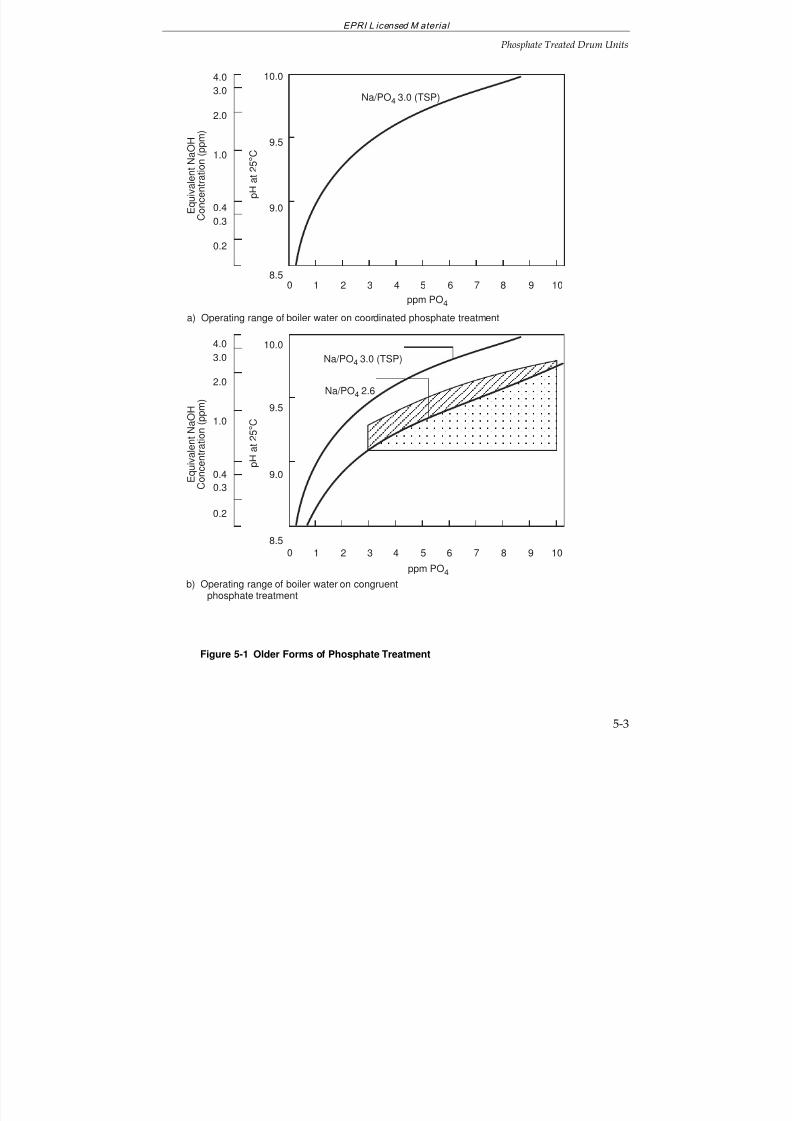
7/18/2019 EPRI Start Up, Lay Up & Shut Down Guidelines for Chemist
http://slidepdf.com/reader/full/epri-start-up-lay-up-shut-down-guidelines-for-chemist 129/256
EPRI L icensed M aterial
Phosphate Treated Drum Units
5-3
a) Operating range of boiler water on coordinated phosphate treatmentppm PO4
E q u i v a l e n t N a O
H
C o n c e n t r a t i o n ( p
p m )
0 1 2 3 4 5 6 7 8 9 10
Na/PO4
3.0 (TSP)
4.0
3.0
2.0
1.0
0.4
0.3
0.2
p H
a t 2 5 ° C
10.0
9.0
9.5
8.5
b) Operating range of boiler water on congruentphosphate treatment
E q u i v a
l e n t N a O H
C o n c e n t
r a t i o n ( p p m )
4.0
3.0
2.0
1.0
0.4
0.3
0.2
10.0
9.0
9.5
8.5
p H
a t 2 5 ° C
0 1 2 3 4 5 6 7 8 9 10
ppm PO4
Na/PO4
2.6
Na/PO4
3.0 (TSP)
Figure 5-1 Older Forms of Phosphate Treatment
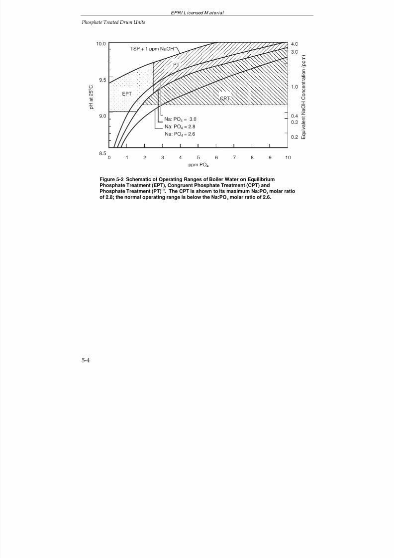
7/18/2019 EPRI Start Up, Lay Up & Shut Down Guidelines for Chemist
http://slidepdf.com/reader/full/epri-start-up-lay-up-shut-down-guidelines-for-chemist 130/256
EPRI L icensed M aterial
Phosphate Treated Drum Units
5-4
ppm PO4
1 3 4 5 6 7 8 92
p H
a t 2 5 ° C
E q u i v a l e n t N a O H
C o n c e n t r a t i o n ( p p m )
100
TSP + 1 ppm NaOH
Na: PO4 = 3.0
Na: PO4 = 2.8
Na: PO4 = 2.6
PT
CPTEPT
3.0
0.4
4.0
1.0
0.3
0.2
8.5
9.5
9.0
10.0
Figure 5-2 Schematic of Operating Ranges of Boiler Water on EquilibriumPhosphate Treatment (EPT), Congruent Phosphate Treatment (CPT) andPhosphate Treatment (PT)
(1). The CPT is shown to its maximum Na:PO
4 molar ratio
of 2.8; the normal operating range is below the Na:PO4 molar ratio of 2.6.

7/18/2019 EPRI Start Up, Lay Up & Shut Down Guidelines for Chemist
http://slidepdf.com/reader/full/epri-start-up-lay-up-shut-down-guidelines-for-chemist 131/256
EPRI Licensed Material
5-5
Figure 5-3 Cycle Chemistry Diagram for a Drum Unit on Equilibrium Phosphate Treatment (Plants With Reheat)—Core Parameters Marked.

7/18/2019 EPRI Start Up, Lay Up & Shut Down Guidelines for Chemist
http://slidepdf.com/reader/full/epri-start-up-lay-up-shut-down-guidelines-for-chemist 132/256
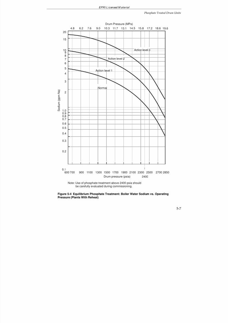
7/18/2019 EPRI Start Up, Lay Up & Shut Down Guidelines for Chemist
http://slidepdf.com/reader/full/epri-start-up-lay-up-shut-down-guidelines-for-chemist 133/256
EPRI L icensed M aterial
Phosphate Treated Drum Units
5-7
600 700 900 1100 1300 1500 1700 1900 2100 2300 2500 2700 2850
Drum pressure (psia)
S o d i u m ( p
p m N
a )
2400
Note: Use of phosphate treatment above 2400 psia shouldbe carefully evaluated during commissioning.
Normal
0.3
0.4
0.5
0.6
0.70.80.91.0
0.2
0.1
2
3
4
5
6
7
89
10
15
20
Action level 1
Action level 3
Action level 2
11.7 13.19.06.2 17.2 19.614.57.6 10.3 15.8 18.64.8
Drum Pressure (MPa)
Figure 5-4 Equilibrium Phosphate Treatment: Boiler Water Sodium vs. OperatingPressure (Plants With Reheat)
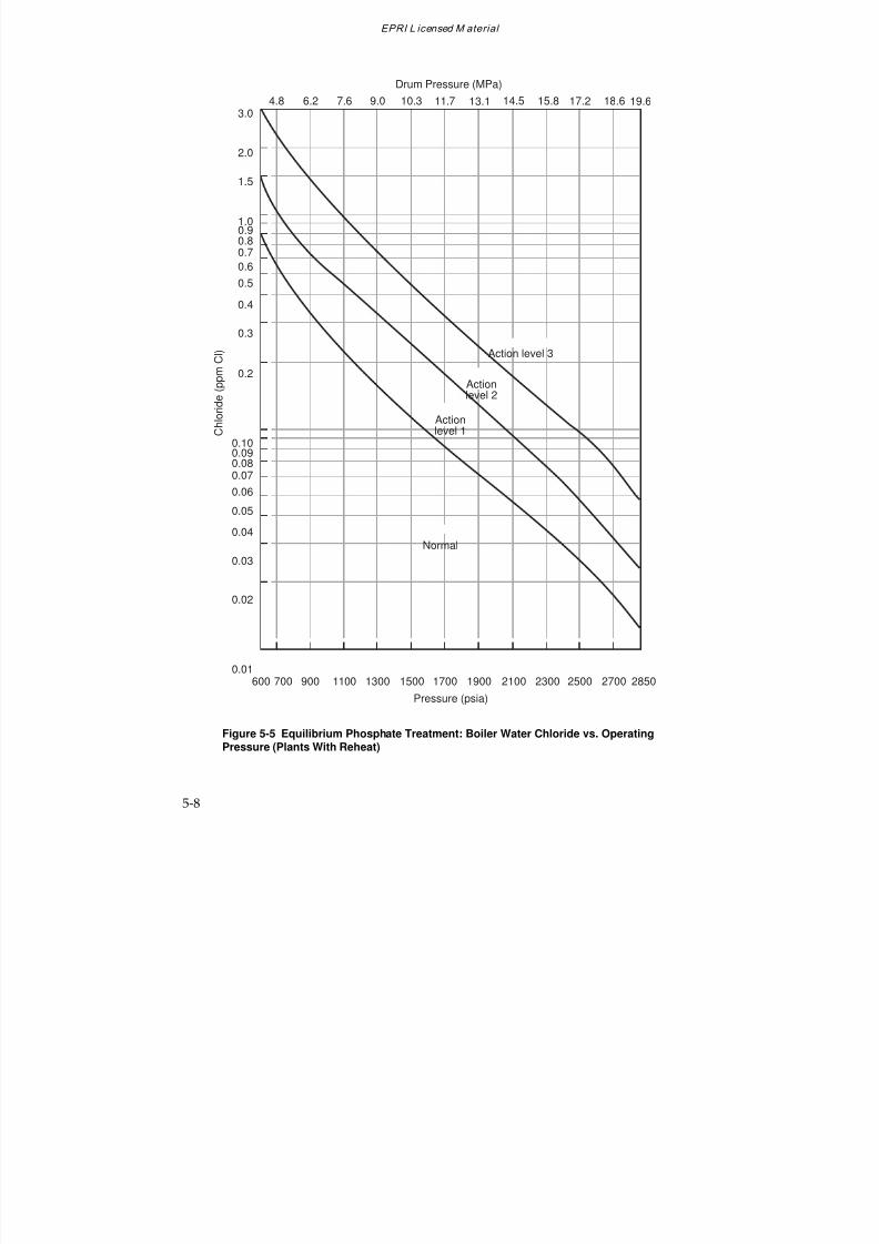
7/18/2019 EPRI Start Up, Lay Up & Shut Down Guidelines for Chemist
http://slidepdf.com/reader/full/epri-start-up-lay-up-shut-down-guidelines-for-chemist 134/256
EPRI L icensed M aterial
5-8
1.0
0.80.7
0.2
0.6
0.5
0.4
0.3
0.9
Pressure (psia)
3.0
2.0
1.5
1300 1700700 15001100600 2500 28502100 270023001900900
C h l o r i d e ( p p m C
l )
Actionlevel 2
Actionlevel 1
Action level 3
0.10
0.080.07
0.02
0.06
0.05
0.04
0.03
0.09
0.01
Normal
11.7 13.19.06.2 17.2 19.614.57.6 10.3 15.8 18.64.8
Drum Pressure (MPa)
Figure 5-5 Equilibrium Phosphate Treatment: Boiler Water Chloride vs. OperatingPressure (Plants With Reheat)
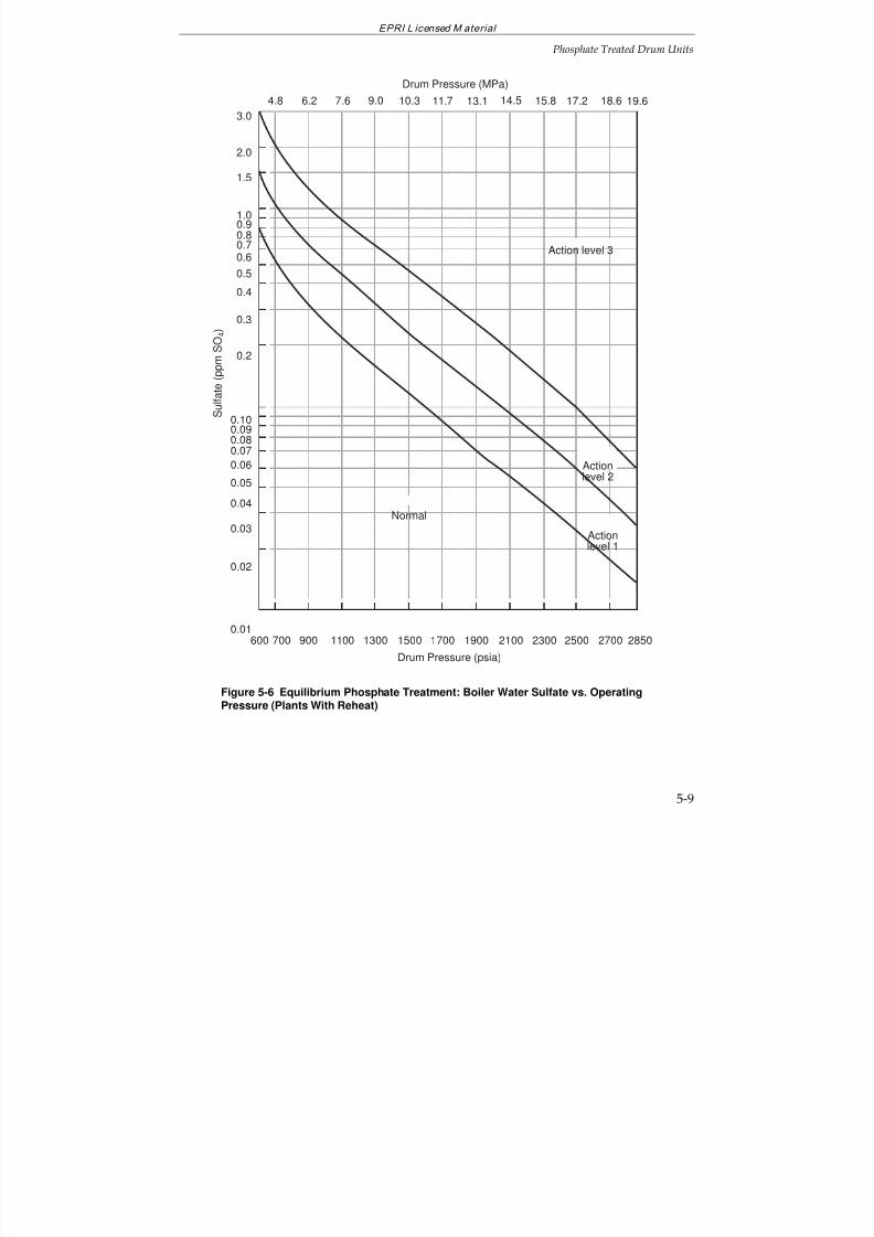
7/18/2019 EPRI Start Up, Lay Up & Shut Down Guidelines for Chemist
http://slidepdf.com/reader/full/epri-start-up-lay-up-shut-down-guidelines-for-chemist 135/256
EPRI L icensed M aterial
Phosphate Treated Drum Units
5-9
1.0
0.80.7
0.2
0.6
0.5
0.4
0.3
0.9
Drum Pressure (psia)
3.0
2.0
1.5
1300 1700700 15001100600 2500 28502100 270023001900900
S u l f a t e ( p p m S
O 4
)
Actionlevel 2
Normal
Actionlevel 1
Action level 3
0.10
0.080.07
0.02
0.06
0.05
0.04
0.03
0.09
0.01
11.7 13.19.06.2 17.2 19.614.57.6 10.3 15.8 18.64.8
Drum Pressure (MPa)
Figure 5-6 Equilibrium Phosphate Treatment: Boiler Water Sulfate vs. OperatingPressure (Plants With Reheat)
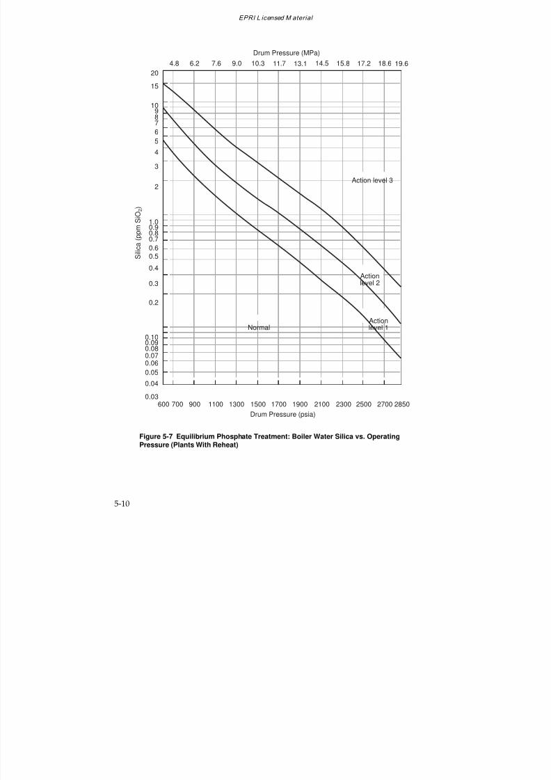
7/18/2019 EPRI Start Up, Lay Up & Shut Down Guidelines for Chemist
http://slidepdf.com/reader/full/epri-start-up-lay-up-shut-down-guidelines-for-chemist 136/256
EPRI L icensed M aterial
5-10
Drum Pressure (psia)
1300 1700700 15001100600 2500 28502100 270023001900900
S i l i c a ( p p m S
i O 2 )
Actionlevel 2
NormalActionlevel 1
Action level 3
0.8
10
87
2
6
5
4
3
9
0.10
0.080.070.06
0.05
0.04
0.03
0.09
20
15
1.0
0.7
0.2
0.6
0.5
0.4
0.3
0.9
11.7 13.19.06.2 17.2 19.614.57.6 10.3 15.8 18.64.8
Drum Pressure (MPa)
Figure 5-7 Equilibrium Phosphate Treatment: Boiler Water Silica vs. OperatingPressure (Plants With Reheat)
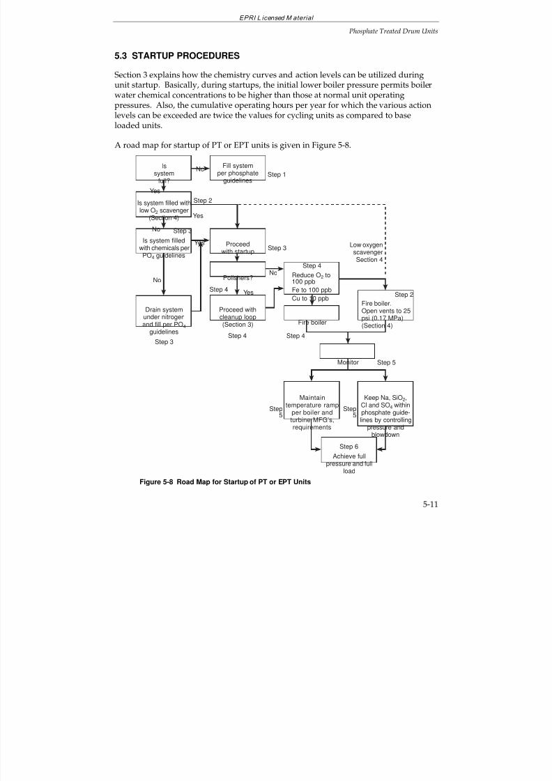
7/18/2019 EPRI Start Up, Lay Up & Shut Down Guidelines for Chemist
http://slidepdf.com/reader/full/epri-start-up-lay-up-shut-down-guidelines-for-chemist 137/256
EPRI L icensed M aterial
Phosphate Treated Drum Units
5-11
5.3 STARTUP PROCEDURES
Section 3 explains how the chemistry curves and action levels can be utilized duringunit startup. Basically, during startups, the initial lower boiler pressure permits boilerwater chemical concentrations to be higher than those at normal unit operating
pressures. Also, the cumulative operating hours per year for which the various actionlevels can be exceeded are twice the values for cycling units as compared to baseloaded units.
A road map for startup of PT or EPT units is given in Figure 5-8.
No
Yes
Polishers?
Fire boiler
Monitor
Fire boiler.Open vents to 25
psi (0.17 MPa)(Section 4)
Reduce O2 to100 ppb
Fe to 100 ppb
Cu to 10 ppb
Proceed with
cleanup loop(Section 3)
Is system filled with chemicals per
PO4 guidelines
Is system filled with
low O2 scavenger(Section 4)
Maintaintemperature ramp
per boiler and
turbine MFG’s,requirements
Keep Na, SiO2,Cl and SO4 withinphosphate guide-
lines by controllingpressure andblowdown
Drain system
under nitrogenand fill per PO4
guidelines
Proceedwith startup
Step 6
Step 5
Step 4Step 4Step 3
No
Yes
Step 2
Step 3
Step 4
Step 3
No
Yes
Issystem
full?Step 1
Low oxygenscavengerSection 4
Fill systemper phosphate
guidelines
Achieve fullpressure and full
load
Step 4
No
Step 2
Step5
Step5
Yes
Figure 5-8 Road Map for Startup of PT or EPT Units
7/18/2019 EPRI Start Up, Lay Up & Shut Down Guidelines for Chemist
http://slidepdf.com/reader/full/epri-start-up-lay-up-shut-down-guidelines-for-chemist 138/256
EPRI L icensed M aterial
5-12
Road Map
The road map for startup of units operating with PT or EPT, Figure 5-8, can be dividedinto 6 steps:
Step 1—System Stored Dry
If the system has been stored dry (Section 4), it should be filled with water which meetsthe EPRI Guidelines for PT or EPT units
(1).
Step 2—System Stored Wet: Low Oxygen Scavenger (Refer to Section 4)
If the system has been stored using the low oxygen scavenger procedure (Step 6 inSection 4.8), the boiler can be fired immediately. The boiler vents are kept open to 25psi (0.2 MPa) to remove any excess ammonia.
Step 3—System Stored Wet: Excess Ammonia and Hydrazine (Refer to Section 4)
If the system has been stored wet with a surplus of ammonia and hydrazine, it must bedrained under nitrogen and refilled with water meeting the PT or EPT Guidelines (1).(See Figure 5-3 for units operating with EPT). The startup of the unit can then proceed.
Step 4—Cleanup and Firing Boiler
The following limits for the boiler feedwater are required prior to firing the boiler:
Oxygen
100 ppb
Iron
100 ppb
Copper
10 ppb
During startup, the levels of corrosion products (iron and copper) can be very highinitially and silica may also be a problem.
Achieving the above limits is greatly facilitated through the use of condensate polishingand/or condensate filtration (See Section 3). When these limits are attained, the boiler
can be fired.
Attainment of the prefiring limits will be more difficult in units not equipped withcondensate polisher and/or filtration equipment. Best control will require closecompliance with the guidelines for unit shutdown and layup.
7/18/2019 EPRI Start Up, Lay Up & Shut Down Guidelines for Chemist
http://slidepdf.com/reader/full/epri-start-up-lay-up-shut-down-guidelines-for-chemist 139/256
EPRI L icensed M aterial
Phosphate Treated Drum Units
5-13
Step 5—Monitoring
After firing the boiler, monitoring must be fully implemented, both for chemistryparameters, and to ensure that temperature ramps are maintained according to theturbine and boiler manufacturer’s specifications.
During startup, the concentration vs. pressure curves can be utilized to control sodium,silica, chlorides and sulfates (for example see Figures 5-4 to 5-7 for EPT, and thephosphate guidelines for PT
(1)). Boiler pressure should remain at reduced levels such
that these limits are maintained before pressure can be increased to the next stage.Maximum use of blowdown and condensate polishing (if available) will minimizestartup times.
During startup, any chemical excursions must be dealt with quickly and effectively.Increases in feedwater sodium and cation conductivity may indicate contaminationfrom the makeup system, contamination from chemical cleaning operations, condensatepolisher malfunction or, most likely, condenser leakage. The source must be found andthe problem corrected at once. Excursions affecting (lowering) boiler water pH must becorrected immediately by feeding trisodium phosphate or 1-2 ppm of caustic.
Effects of cycle contamination are magnified at startup due to relatively low flow ratesfor condensate, feedwater and steam. Cation conductivity may increase as a result of air ingress due to either aeration of water during the shutdown period or air in-leakageduring startup. The change to boiler water chemistry will be minimal compared tocontamination involving the makeup system, chemical cleaning activities, condensatepolishers or condenser leaks.
Step 6—Full Load
Full load can be achieved when chemical limits are within PT or EPT Guidelines(1)
.
5.4 CYCLING AND PEAKING UNITS
Cycling and peaking units have been previously defined (Section 3). These units aresubject to frequent startups and shutdowns, with generally short-term layupprocedures practiced, when required (see Section 4).
5.5 SHUTDOWN PROCEDURES
A road map for shutdown of PT or EPT units is presented in Figure 5-9. Shutdownshould be closely related to layup (Section 4) which in turn depends on the anticipatedoutage length. Based upon this road map, shutdown should proceed in the followingmanner:
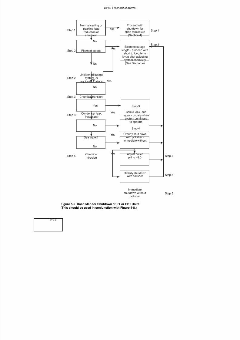
7/18/2019 EPRI Start Up, Lay Up & Shut Down Guidelines for Chemist
http://slidepdf.com/reader/full/epri-start-up-lay-up-shut-down-guidelines-for-chemist 140/256
EPRI L icensed M aterial
5-14
Yes
Chemical transient
No
No
Yes
Step 1 YesStep 1
Proceed withshutdown for
short term layup(Section 4)
Estimate outagelength - proceed with
short to long termlayup after adjusting
system chemistry(See Section 4)
Isolate leak andrepair - usually while
system continuesto operate
Orderly shut down
with polisher -immediate without
Adjust boilerpH to >8.0
Orderly shutdownwith polisher
Immediateshutdown without
polisher
Normal cycling orpeaking loadreduction orshutdown
Planned outage
Condenser leak,freshwater
Sea water?
Chemicalintrusion
Yes
Unplanned outagesystem or
equipment failure
No
No
Yes
No
Yes
No
Yes
Step 2
Step 2
Step 3
Step 3
Step 4
Step 5 Step 5
Step 5
Step 5
Step 2
Step 3
Figure 5-9 Road Map for Shutdown of PT or EPT Units(This should be used in conjunction with Figure 4-8.)
7/18/2019 EPRI Start Up, Lay Up & Shut Down Guidelines for Chemist
http://slidepdf.com/reader/full/epri-start-up-lay-up-shut-down-guidelines-for-chemist 141/256
EPRI L icensed M aterial
Phosphate Treated Drum Units
5-15
Road Map
The road map for shutdown for PT and EPT units, Figure 5-9, should be used inconjunction with Figure 4-8, “Road Map to Develop Shutdown and Layup GuidelinesCommon to Most Units.” Figure 5-9 can be divided into 5 steps:
Step 1—Normal Cycling or Peaking: Load Reduction or Shutdown
Normal cycling or peaking load reduction or shutdown presumes a short term layup asdescribed in Section 4.
An orderly reduction of load can be performed for routine cycling operations. Also, anorderly reduction of load or unit shutdown can be performed when contamination isminimal, as determined by chemical monitoring during such transients.
During orderly load reductions, the condensate cycle and boiler chemical limits should
be adjusted to conform with the phosphate chemistry guidelines(1) for PT or EPT, asapplicable. (Layup procedures are covered in Section 4 of this document.)
Particular care should be exercised to prevent oxygen ingress during this period, and blowdown should be maintained at an appropriate level to remove contaminants fromthe system.
During shutdown, any indication of phosphate hideout return (increased levels of phosphate, change of pH, etc.) indicates that the boiler has not been operating at theequilibrium level during normal operation. This should be corrected during normal
operation by following the procedure given in the phosphate guidelines to determinethe optimum (equilibrium) level of phosphate(1)
.
Step 2—Outages
Planned or unplanned outages may be short or long term, depending upon systemdemand or the extent of work required to return the unit to operation. The length of time required for maintenance must be estimated and, depending upon this estimate,short term or long term layup should be initiated (Section 4). Chemistry should beadjusted prior to shutdown, as indicated in the various options delineated in Section 4,Figure 4-8.
An unplanned outage due to an equipment or system failure can be treated as for aplanned outage.
7/18/2019 EPRI Start Up, Lay Up & Shut Down Guidelines for Chemist
http://slidepdf.com/reader/full/epri-start-up-lay-up-shut-down-guidelines-for-chemist 142/256
EPRI L icensed M aterial
5-16
Step 3—Chemical Transients: Condenser Leak (Fresh Water)
For condenser leaks with fresh, relatively low solids cooling water, the leak cangenerally be isolated and repaired while the unit is still operational under reduced load(divided water box). Otherwise the unit should be shut down, and leaks isolated andrepaired.
Step 4—Chemical Transients: Condenser Leaks (Sea Water)
Serious damage can occur to units within a short period of time with intrusion of seawater. Without condensate polishing, the boiler must be shut down immediately uponidentifying a significant condenser leak. The addition of extra trisodium phosphate or1-2 ppm of caustic may also be required as the boiler water pH drops.
With condensate polishing, the unit can generally be shut down in an orderly fashion,
especially if the polishers are of the deep bed type. With deep bed polishers, it isprudent to maintain one or more vessels in the hydrogen form for added protectionagainst condenser leakage.
Powdered resin condensate polishers have less capability for removal of dissolvedimpurities than deep bed polishers. If the leak is small, the use of powdered resinsystems may permit an orderly unit shutdown.
Chemistry monitoring is especially important when a sea water condenser leak issuspected. Boiler water pH is critical and condensate cation conductivity and sodiumwill assist in estimating the extent of the leak.
In any event, the unit should be shut down to repair the condenser leak. Depending onan evaluation of cycle and boiler chemistry, the shutdown will be immediate ororderly, as outlined above.
Substantial intrusion of sea water into the boiler will require that the unit be drained,flushed and refilled with condensate quality water plus chemicals consistent withoperating requirements of PT or EPT, as applicable.
Step 5—Chemical Transients: Chemical Intrusion
Some of the many causes of chemical intrusion (in addition to condenser leakage)include:
Makeup water system malfunction
Polisher leakage
7/18/2019 EPRI Start Up, Lay Up & Shut Down Guidelines for Chemist
http://slidepdf.com/reader/full/epri-start-up-lay-up-shut-down-guidelines-for-chemist 143/256
EPRI L icensed M aterial
Phosphate Treated Drum Units
5-17
— Poor regeneration
— Acid or caustic contamination
Chemical cleaning residue; acid, caustic, other
Maintenance chemicals and preservatives
Silica from flyash or other contaminants from maintenance activities
Minor chemical intrusions can be controlled by increasing boiler blowdown, andemployment of idle condensate polishers, if available.
More serious chemical intrusions may require adjustment of boiler pH throughaddition of more trisodium phosphate or 1-2 ppm of caustic. If these treatments areunsuccessful, the unit must be shutdown (orderly with polisher, immediate without
polisher) if the pH falls below 8.0 (Figure 5-3). The unit then requires carefulinspection to determine possible damage, and the necessity for repair and possiblechemical cleaning prior to restart.
Intrusion of chemical contamination requires immediate unit shutdown, draining andflushing the unit. Inspection of critical areas of the system (boiler, superheater, turbine,etc.) should be performed to assess the effects of chemical intrusion on the system.Chemical cleaning of the boiler, superheater and turbine may be required dependingupon the results of the inspection. Equipment repairs may also be required. In suchcase, a longterm layup will be required. (See Section 4.)
During emergency shutdowns, such as for major sea water leaks and extensivechemical contamination, immediate unit shutdown is required. Therefore, little can bedone to adjust cycle chemistry during shutdown since rapid action is required. Duringsuch occasions, the unit should be drained, flushed and inspected to assess damages, asoutlined previously. Restarting the unit will be contingent upon this inspection, as willlayup provisions.
5.6 MIXED METALLURGY SYSTEMS
As mentioned in Section 4, the metallurgy of condensers and feedwater heaters must becarefully considered when establishing chemistry parameters for startup, shutdown,and layup. A recent EPRI report
(3) on the State-of-Knowledge of Copper in Fossil Plant
Cycles describes the procedures required to prevent serious problems related to copperalloy corrosion, such as copper volatilization and deposition. For systems containingcopper alloys, it is most important to maintain a reducing atmosphere (ORP < 0mV) atall times. During operation this is generally accomplished by the use of suitableconcentrations of hydrazine with the addition of ammonia to regulate pH in the range
7/18/2019 EPRI Start Up, Lay Up & Shut Down Guidelines for Chemist
http://slidepdf.com/reader/full/epri-start-up-lay-up-shut-down-guidelines-for-chemist 144/256
EPRI L icensed M aterial
5-18
of 8.8-9.1. The reducing environment must also be maintained during the shutdownand layup periods. Oxygen ingress must be avoided, as this will increase the corrosionrate of copper alloys by changing the predominant surface oxide to cupric oxide.
The cycling of units, accompanied by periods of layup, materially increases the risk of
copper alloy attack, because of the opportunities for oxygen ingress with associatedincreases of ORP into the oxidizing range. Therefore, chemistry control under theseconditions, requires much more attention than for base loaded units.
The reader is referred to Sections 6.3 and 6.4 for more comprehensive coverage of mixed versus all-ferrous feedwater systems for drum units operating with AVTfeedwater.
5.7 CORRECTIVE ACTIONS
Typical corrective actions to respond to out-of-specification steam and/or waterchemistry conditions for PT and EPT units are presented in Section 6 of the phosphateguidelines
(1) (“Corrective Actions”). Individual corrective action tabulations are given
for the following:
Makeup treatment system effluent
Condensate storage tank effluent
Condenser leak detection trays
Air removal system exhaust
Condensate pump discharge
Deaerator inlet
Deaerator outlet
Economizer inlet
Boiler water
Reheat steam
5.8 LAYUP
Layup procedures are presented in Section 4, and a layup road map, which can beapplied to phosphate treated (PT) and equilibrium phosphate treated (EPT) units, is
7/18/2019 EPRI Start Up, Lay Up & Shut Down Guidelines for Chemist
http://slidepdf.com/reader/full/epri-start-up-lay-up-shut-down-guidelines-for-chemist 145/256
EPRI L icensed M aterial
Phosphate Treated Drum Units
5-19
depicted in Figure 4-8. Layup procedures fall into two categories—wet or dry. Withineach method, customization is possible (and encouraged) to suit the needs of the utilityor individual unit.
As described in Section 4, nitrogen blanketing for the boiler and feedwater system
components has been used to great advantage to prevent air ingress and subsequentcorrosion.
Particular attention should be given to maintaining proper layup conditions for theturbine (Section 4).
Also, the use of minimal levels of hydrazine or hydrazine substitute, introduced intothe boiler upon layup has permitted unit startups without the necessity to drain andrefill. This procedure reduces startup time and is environmentally sound. Thisprocedure is referenced in Step 6 in Section 4.8.
5.9 REFERENCES
1. Cycle Chemistry Guidelines for Fossil Plants: Phosphate Treatment for Drum Units. TR-103665. Palo Alto, Calif.: Electric Power Research Institute, December 1994.
2. B. Dooley, J. Matthews, R. Pate and J. Taylor. “Optimum Chemistry for ‘All-Ferrous’ Feedwater Systems: Why Use an Oxygen Scavenger?” IWC Paper I94-53,International Water Conference, Pittsburgh, PA, Oct. 31–Nov. 2, 1994.
3. State-of-Knowledge of Copper in Fossil Plant Cycles. TR-108460. Palo Alto, CA: Electric
Power Research Institute, September 1997.

7/18/2019 EPRI Start Up, Lay Up & Shut Down Guidelines for Chemist
http://slidepdf.com/reader/full/epri-start-up-lay-up-shut-down-guidelines-for-chemist 146/256
7/18/2019 EPRI Start Up, Lay Up & Shut Down Guidelines for Chemist
http://slidepdf.com/reader/full/epri-start-up-lay-up-shut-down-guidelines-for-chemist 147/256
EPRI L icensed M aterial
6-1
6
ALL-VOLATILE TREATMENT
6.1 INTRODUCTION
All-volatile treatment must be used for once-through units, to avoid deposition of non-volatile compounds in the boiler water/steam circuit. With the “traditional” form of all-volatile treatment (AVT), ammonia and hydrazine is added to the feedwater toprovide chemical conditions that protect the feedwater heaters, boiler, superheaters,reheaters and turbine against corrosion, without further chemical additions.
An alternative chemical treatment for once-through units is oxygenated treatment (OT -see Section 7), where instead of hydrazine, oxygen is added in addition to theammonia. An intermediate form of conditioning is also being used, where onlyammonia, without hydrazine or oxygen, is added to the feedwater. With all threealternatives, the degree of protection against corrosion provided by the chemicaladditives is strictly limited. Therefore, it is essential to maintain high purity feedwaterand to prevent the ingress of impurities, both while on-load and during off-loadconditions.
All-volatile treatment can also be used for units with drum-type boilers, provided highpurity feedwater is available and the buildup of impurities in the boiler water is strictlycontrolled. The absence of a solid alkalizing chemical in the boiler water gives lessprotection against corrosion, but, because there should be lower concentrations of impurities in the boiler water, it also reduces the risk of carrying over boiler water saltsand solid alkalizing chemicals into the steam. If the high purity feed and boiler waterconditions cannot be maintained during startup, operation and shutdown, it may benecessary to resort to another form of chemical conditioning, such as phosphate orcaustic treatment. The Selection and Optimization document provides advice andguidance on the optimum boiler water and feedwater choices for drum units
(1).
Guidance on the use of AVT was given in the EPRI Interim Consensus Guidelines(2)
in1986. Cycle diagrams were provided for once-through and drum-type boilers with allferrous and mixed Fe-Cu metallurgy feedwater heating systems. The normal limits andthree action levels were given for sodium, chloride, sulfate, silica and cationconductivities for feedwater and steam for once-through boilers. A range of pressureswas considered for drum boilers, with and without reheat, with additional pressurecurves for the normal limits and three action levels for sodium, chloride, sulfate and
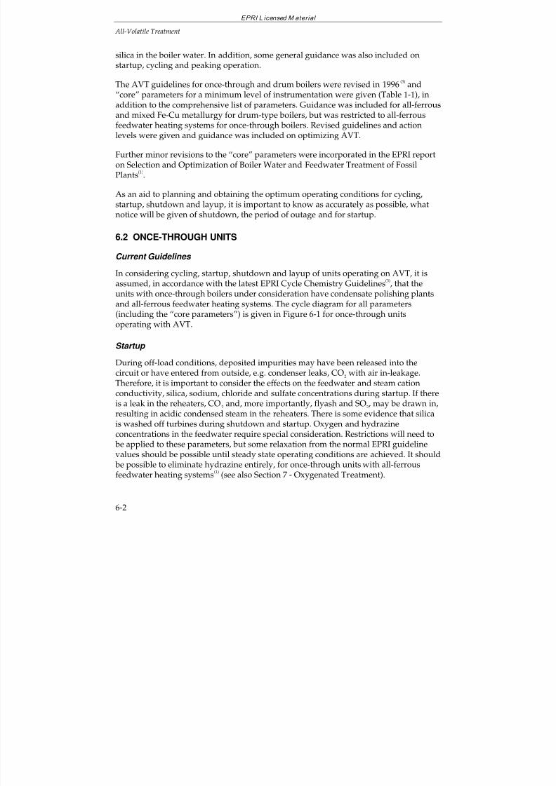
7/18/2019 EPRI Start Up, Lay Up & Shut Down Guidelines for Chemist
http://slidepdf.com/reader/full/epri-start-up-lay-up-shut-down-guidelines-for-chemist 148/256
EPRI L icensed M aterial
All-Volatile Treatment
6-2
silica in the boiler water. In addition, some general guidance was also included onstartup, cycling and peaking operation.
The AVT guidelines for once-through and drum boilers were revised in 1996(3)
and“core” parameters for a minimum level of instrumentation were given (Table 1-1), in
addition to the comprehensive list of parameters. Guidance was included for all-ferrousand mixed Fe-Cu metallurgy for drum-type boilers, but was restricted to all-ferrousfeedwater heating systems for once-through boilers. Revised guidelines and actionlevels were given and guidance was included on optimizing AVT.
Further minor revisions to the “core” parameters were incorporated in the EPRI reporton Selection and Optimization of Boiler Water and Feedwater Treatment of FossilPlants
(1).
As an aid to planning and obtaining the optimum operating conditions for cycling,startup, shutdown and layup, it is important to know as accurately as possible, what
notice will be given of shutdown, the period of outage and for startup.
6.2 ONCE-THROUGH UNITS
Current Guidelines
In considering cycling, startup, shutdown and layup of units operating on AVT, it isassumed, in accordance with the latest EPRI Cycle Chemistry Guidelines
(3), that the
units with once-through boilers under consideration have condensate polishing plantsand all-ferrous feedwater heating systems. The cycle diagram for all parameters
(including the “core parameters”) is given in Figure 6-1 for once-through unitsoperating with AVT.
Startup
During off-load conditions, deposited impurities may have been released into thecircuit or have entered from outside, e.g. condenser leaks, CO2 with air in-leakage.Therefore, it is important to consider the effects on the feedwater and steam cationconductivity, silica, sodium, chloride and sulfate concentrations during startup. If thereis a leak in the reheaters, CO 2 and, more importantly, flyash and SO2, may be drawn in,resulting in acidic condensed steam in the reheaters. There is some evidence that silica
is washed off turbines during shutdown and startup. Oxygen and hydrazineconcentrations in the feedwater require special consideration. Restrictions will need to be applied to these parameters, but some relaxation from the normal EPRI guidelinevalues should be possible until steady state operating conditions are achieved. It should be possible to eliminate hydrazine entirely, for once-through units with all-ferrousfeedwater heating systems
(1) (see also Section 7 - Oxygenated Treatment).
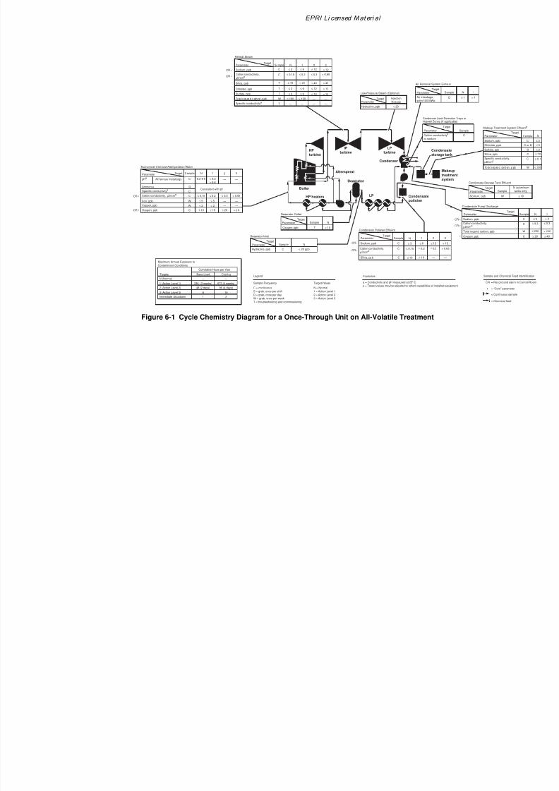
7/18/2019 EPRI Start Up, Lay Up & Shut Down Guidelines for Chemist
http://slidepdf.com/reader/full/epri-start-up-lay-up-shut-down-guidelines-for-chemist 149/256
EPRI Li censed Mat eri al
Specific conductivitya
Cation conductivity, µS/cma
HP
turbine
LP
turbine
Deaerator
Attemperat
Boiler
LP Condensate
polisher
Makeup
treatment
system
Condensate
storage tank
Condenser
IP
turbine
HP heaters
N (Normal)
Maximum Annual Exposure to
Contaminant Conditions
Targets
Cumulative Hours per Year
Base Load Cycling
1 (Action Level 1)
2 (Action Level 2)
3 (Action Level 3)
—
336 ( 2 weeks)
48 (2 days)
8
1Immediate Shutdown
—
672 (4 weeks)
96 (4 days)
16
2
Hydrazine, ppb
Deaerator Outlet
Parameter
TargetSample N
C < 20 ppb
Oxygen, ppb
Deaerator Inlet
Parameter
TargetSample N
T < 10
Hydrazine, ppb
Low-Pressure Steam (Optional)
ParameterTarget Injection
Dosage
< 20
Air inleakage,
scfm/100 MWe
Air Removal System Exhaust
Parameter
TargetSample N
D ≤ 1
Cation conductivitya
or sodium
Condenser Leak Detection Trays orHotwell Zones (If applicable)
Parameter
Target
Sampl
C
Con
Pa
Sod
Oxy
Tot
•
Cat
µS/
Cation conductivity,
µS/cma
Sodium, ppb
Condensate Polisher Effluent
ParameterTarget
Sample N
Silica, ppb C ≤ 10
C ≤ 0.15
1
> 10
≤ 0.2
2
—
3
—
C ≤ 3 ≤ 6 ≤ 12 > 12CR •
CR • ≤ 0.3 > 0.65
CR •
CR •
Economizer Inlet and Attemperation Water
Parameter Target Sample N
All ferrous metallurgy C 9.2-9.6
1
< 9.2
> 9.6
2
—
3
—
Ammonia D
C
pHa
Consistent with pH
C ≤ 0.15 ≤ 0.2 ≤ 0.3 > 0.65
Iron, ppb
Copper, ppb
Oxygen, ppb
W ≤ 5 > 5 — —
W ≤ 2 > 2 — —
C 1-10 ≤ 15 ≤ 20 > 20
CR •
CR •
Reheat Steam
ParameterTarget
Sample N
Sodium, ppb C ≤ 3
To ta l o rg an ic c arb on , p pb W ≤ 100
Specific conductivitya
T —
Cation conductivity,
µS/cma
C
Silica, ppb T ≤ 10
Chloride, ppb T ≤ 3
Sulfate, ppb T ≤ 3
1
≤ 6
> 100
—
≤ 20
≤ 6
≤ 6
2
≤ 12
—
—
≤ 40
≤ 12
≤ 12
3
> 12
—
—
> 40
> 12
> 12
CR •
CR • ≤ 0.15 ≤ 0.2 ≤ 0.3 > 0.65
N = Normal
1 = Action Level 1
2 = Action Level 2
3 = Action Level 3
Target Values
Legend
C = continuous
S = grab, once per shift
D = grab, once per day
W = grab, once per week
T = troubleshooting and commissioning
Sample Frequency
Footnotes
a = Conductivity and pH measured at 25° C
e = Target values may be adjusted to reflect capabilities of installed equipment
Figure 6-1 Cycle Chemistry Diagram for a Once-Through Unit on All-Volatile Treatment

7/18/2019 EPRI Start Up, Lay Up & Shut Down Guidelines for Chemist
http://slidepdf.com/reader/full/epri-start-up-lay-up-shut-down-guidelines-for-chemist 150/256
All-Volatile Treatment
6-4
Depending on the plant, and the shutdown and layup conditions adopted, several stepswill be required for startup (in addition to filling the boiler following a long shutdownand safely venting the nitrogen, if used). The steps used during startup will be plantspecific and, depending on the practicality, the following stages should be monitored,at least during a trial period:
StageduringStartup CircuitMonitoringa)Circulationviadeaerator pH, ironandcationconductivity b)Circulationviaeconomizer pH, Fe, cationconductivity, oxygenandhydrazinec)Circulationviatheboiler pH, Fe, cationconductivity, silica, sodiumandchlorided)Allowfiring pH, ironandcationconductivity
e)Allowsteamtoturbine pH, ironandcationconductivityf)Turbinetoonethirdload pH, ironandcationconductivityg)Tofullload pH, ironandcationconductivityOnfull load, thenormal EPRIGuidelinesvaluesgiveninFigure6-1shouldbeachieved. Theremayberoomforrelaxation, particularly, asregardssilicainsteam,duringstartup, theearlierstagesofoperationandduringlowloadoperation, providedtheparametersarewithintheEPRIactionlevels1-3. (Notethattheguidelinesarethesameforall operatingpressuresforonce-throughboilers.)Thecoreparameters,sodium, cationconductivityandoxygengivenintheEPRIGuidelinesshouldbemonitoredatthecondensatepumpdischarge, condensatepolisheroutlet, economizerinletandsteam, andalsopH, silicaandiron, ifpossible, atleastduringatrial period.Thenormal operatinglevels, asgivenintheEPRIguidelines, shouldbeachievedassoonaspossible. ThesearegiveninFigure6-1.Aroadmap(decisiontree)showingaschemeforstartupofaonce-throughunitoperatingwithAVTisgiveninFigure6-2. Thetimetakentoachievetherequiredtargetvalueswill beplantdependent. Thisshouldbedeterminedforeachunit, usedasguidanceforsubsequentstartups, andamendedinthelightofoperatingexperience.Theprocedurecanusuallybecurtailedforwarmandhotstarts.Theroadmapforstartupofonce-throughunitsoperatingonAVT, Figure6-2, canbedividedinto7steps.
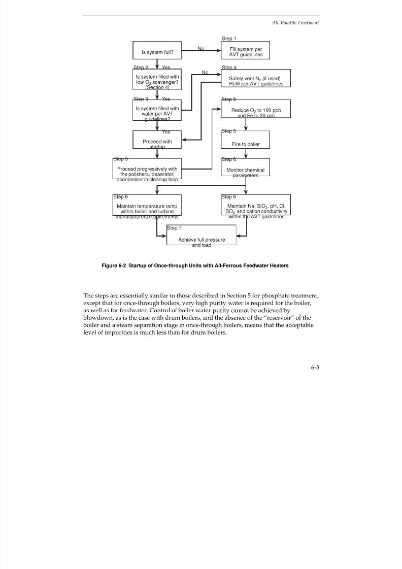
7/18/2019 EPRI Start Up, Lay Up & Shut Down Guidelines for Chemist
http://slidepdf.com/reader/full/epri-start-up-lay-up-shut-down-guidelines-for-chemist 151/256
All-Volatile Treatment
6-5
No
Yes
Step 1
Fill system perAVT guidelines
Monitor chemicalparameters
Achieve full pressureand load
Safely vent N2 (if used)Refill per AVT guidelines
Maintain Na, SiO2, pH, Cl,SO4 and cation conductivity
within the AVT guidelines
Is system full?
Is system filled withlow O2 scavenger?
(Section 4)
Is system filled withwater per AVT
guidelines?
Proceed withstartup
Maintain temperature rampwithin boiler and turbine
manufacturers requirements
Proceed progressively withthe polishers, deaerator,
economiser in cleanup loop
Step 4
Step 5
Step 5
Step 6
Step 6Step 6
Step 5
Step 3
Step 2
Yes
Yes
No
Step 7
Reduce O2 to 100 ppband Fe to 30 ppb
Fire to boiler
Figure 6-2 Startup of Once-through Units with All-Ferrous Feedwater Heaters
The steps are essentially similar to those described in Section 5 for phosphate treatment,except that for once-through boilers, very high purity water is required for the boiler,as well as for feedwater. Control of boiler water purity cannot be achieved by blowdown, as is the case with drum boilers, and the absence of the “reservoir” of the boiler and a steam separation stage in once-through boilers, means that the acceptablelevel of impurities is much less than for drum boilers.

7/18/2019 EPRI Start Up, Lay Up & Shut Down Guidelines for Chemist
http://slidepdf.com/reader/full/epri-start-up-lay-up-shut-down-guidelines-for-chemist 152/256
All-Volatile Treatment
6-6
Step 1 - System Stored Dry
If the system has been stored dry (Section 4), it should be filled with water which meetsthe EPRI Guidelines for once-through units operating on AVT (3).
Step 2 - Systems Stored Wet: Low Oxygen Scavenger
If the system has been stored using the low oxygen scavenger procedure (Section 4), the boiler can be fired immediately.
Step 3 - System Stored Wet: Excess Ammonia and Hydrazine
If the system has been stored wet with a surplus of ammonia and hydrazine (Section 4),it must be drained under nitrogen and refilled with water meeting the EPRI Guidelinesfor once-through units operating on AVT
(3).
Step 4 - System Stored using Nitrogen
If the system has been filled with nitrogen or filled with water, using nitrogen capping,the nitrogen must be safely vented and the boiler refilled, if necessary, with watermeeting the EPRI Guidelines for once-through units operating on AVT
(3). Startup of the
unit can then proceed.
Step 5 - Cleanup and Firing Boiler
The following limits for the boiler feedwater are required prior to firing the boiler:
Oxygen < 100 ppb
Iron < 30 ppbDuring startup, the levels of corrosion products (iron) can be very high initially andsilica may also be a problem. Achieving these limits is greatly facilitated by usingcondensate polishing (See Section 3). When these limits are attained, the boiler can befired.
Step 6 - Monitoring
After firing the boiler, monitoring must be fully implemented, both for chemistryparameters, and to ensure that temperature ramps are maintained according to the boiler and turbine manufacturer’s specifications.
During startup, any chemical excursions must be dealt with quickly and effectively.Increases in feedwater sodium and cation conductivity may indicate contaminationfrom the makeup system, contamination from chemical cleaning operations, condensatepolisher malfunction or condenser leakage. The source must be found and the problemcorrected at once.

7/18/2019 EPRI Start Up, Lay Up & Shut Down Guidelines for Chemist
http://slidepdf.com/reader/full/epri-start-up-lay-up-shut-down-guidelines-for-chemist 153/256
All-Volatile Treatment
6-7
Step 7 - Full Load
Full load can be achieved when chemical limits are within the EPRI Guidelines foronce-through units operating on AVT(3).
Shutdown
Information is given in Section 4.8 on Shutdown and below for various plannedshutdown conditions.
Short shutdown (overnight/weekend) - No change to chemical conditions, leave plantpressurized. Maintain condensate circulation and deaerator pressure. Raise the pHwhen coming off-load.
Intermediate shutdown (weekend/week) - Leave plant pressurized, raise pH and thehydrazine concentration (if used), when coming off-load.
Long shutdown (longer than 1 week) - Drain under nitrogen or from high temperature(e.g. 130°C) and maintain the boiler, superheaters and reheaters dry. Continue asdescribed under “Layup”.
Unplanned shutdowns also occur and, by their very nature, are unpredictable.Therefore, it is difficult to give specific advice, except that, by using circulation,endeavor to achieve the most appropriate conditions given above.
During shutdown, if there is a leak in the reheaters, CO2 and, more importantly, flyash
and SO2, may be drawn in, resulting in acidic condensed steam in the reheaters. There
is also evidence that silica is washed off turbines during shutdown.
A road map showing a scheme for shutdown of a once-through boiler operating withAVT is given in Figure 6-3. The time taken to achieve stable shutdown conditions will be plant dependent. This should be determined for each unit, as guidance forsubsequent shutdowns and amended in the light of operating experience.
The road map for shutdown of once-through units operating on AVT, Figure 6-3, can be divided into 5 steps.
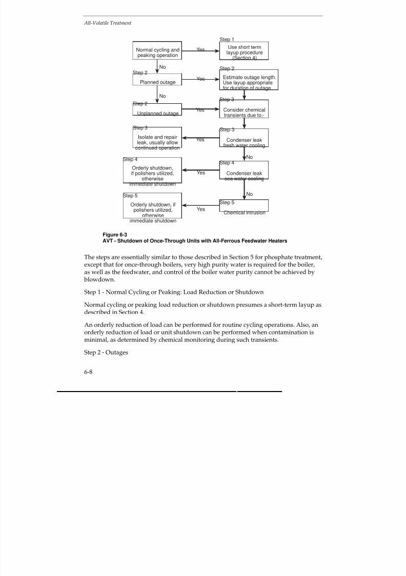
7/18/2019 EPRI Start Up, Lay Up & Shut Down Guidelines for Chemist
http://slidepdf.com/reader/full/epri-start-up-lay-up-shut-down-guidelines-for-chemist 154/256
All-Volatile Treatment
6-8
Estimate outage length.Use layup appropriatefor duration of outage
No
Step 1
Use short termlayup procedure
(Section 4)
Isolate and repairleak, usually allow
continued operation
Step 2
Step 3
Step 3
Step 2
Yes
Consider chemicaltransients due to:-
Orderly shutdown,if polishers utilized,
otherwiseimmediate shutdown
Normal cycling andpeaking operation
Unplanned outage
Yes
Yes
Yes
Yes
Condenser leakfresh water cooling
Condenser leaksea water cooling
Planned outage
Step 4
Step 2
No
No
Step 3
Step 4
Step 5
Step 5
Orderly shutdown, ifpolishers utilized,
otherwiseimmediate shutdown
YesChemical intrusion
No
Figure 6-3AVT - Shutdown of Once-Through Units with All-Ferrous Feedwater Heaters
The steps are essentially similar to those described in Section 5 for phosphate treatment,except that for once-through boilers, very high purity water is required for the boiler,as well as the feedwater, and control of the boiler water purity cannot be achieved by blowdown.
Step 1 - Normal Cycling or Peaking: Load Reduction or Shutdown
Normal cycling or peaking load reduction or shutdown presumes a short-term layup as
described in Section 4.
An orderly reduction of load can be performed for routine cycling operations. Also, anorderly reduction of load or unit shutdown can be performed when contamination isminimal, as determined by chemical monitoring during such transients.
Step 2 - Outages

7/18/2019 EPRI Start Up, Lay Up & Shut Down Guidelines for Chemist
http://slidepdf.com/reader/full/epri-start-up-lay-up-shut-down-guidelines-for-chemist 155/256
All-Volatile Treatment
6-9
Planned or unplanned outages may be short or long term, depending on systemdemand or the extent of the work required to return the unit to operation. The length of time required for maintenance must be estimated and, depending on this estimate,short term or longterm layup should be initiated (Section 4). Chemistry should beadjusted prior to shutdown, as indicated in the various options delineated in Section 4.8
(Figure 4-8).
An unplanned outage due to an equipment or system failure can be treated as for aplanned outage.
Step 3 - Chemical Transients: Condenser Leaks (Fresh Water)
For condenser leaks with fresh, relatively low dissolved solids cooling water, the leakcan generally be isolated and repaired, while the condensate polishing plant maintainsthe feedwater quality.
Step 4 - Chemical Transients: Condenser Leaks (Sea Water)
Serious damage can occur to units within a short period of time with intrusion of seawater. With condensate polishing, the unit can generally be shut down in an orderlyfashion, especially if the polishers are of the deep bed type. With deep bed polishers, itis prudent to maintain one or more vessels in the hydrogen form for added protectionagainst condenser leakage.
Powdered resin condensate polishers have less capability for removal of dissolvedimpurities than deep bed polishers. If the leak is small, the use of powdered resinsystems may permit an orderly unit shutdown.
Chemical monitoring is especially important when a sea water leak is suspected.Sodium and cation conductivity will assist in estimating the extent of the leak.
In any event, the unit should be shut down to repair the condenser leak. Depending onan evaluation of the cycle chemistry, shutdown will be immediate or orderly, asoutlined above.
Substantial intrusion of sea water into the boiler will require that the unit is drainedand refilled with water meeting the EPRI Guidelines for once-through units operatingon AVT
(3).
7/18/2019 EPRI Start Up, Lay Up & Shut Down Guidelines for Chemist
http://slidepdf.com/reader/full/epri-start-up-lay-up-shut-down-guidelines-for-chemist 156/256
All-Volatile Treatment
6-10
Step 5 - Chemical Transients: Chemical Intrusion
Some of the many causes of chemical intrusion (in addition to condenser leakage)include:
Makeup water system malfunction
Polisher leakage
— Poor regeneration
— Acid or caustic contamination
Chemical cleaning residue; acid, caustic, other
Maintenance chemicals and preservatives
Silica from flyash or other contaminants from maintenance activitiesMinor chemical intrusions can be controlled by employment of idle condensatepolishers, if available.
Intrusion of chemical contamination requires immediate unit shutdown, draining andflushing the unit. Inspection of critical areas of the system (boiler, superheater, turbine,etc) should be performed to assess the effects of chemical intrusion on the system.Chemical cleaning of the boiler, superheater and turbine may be required, dependingon the results of the inspection. Equipment repairs may be required. In such case, along term layup will be required. (See Section 4.)
During emergency shutdowns, such as for major sea water leaks and extensivechemical contamination, immediate unit shutdown is required. Therefore, little can bedone to adjust cycle chemistry during shutdown, since rapid action is required. Duringsuch occasions, the unit should be drained, flushed and inspected to assess damage, asoutlined previously. Restarting the unit will be contingent upon this inspection, as willlayup provisions.
Cycling and Peaking
Special features may be required for once-through units to cycle, such as a turbine bypass (Section 2).
As an aid to planning and obtaining optimum conditions, it is important to know asaccurately as possible, the frequency and duration of cycling and peaking, the noticegiven and the variation of load patterns.
Essentially, cycling and peaking plant should operate according to the outline givenabove for startup, load changes and shutdown.

7/18/2019 EPRI Start Up, Lay Up & Shut Down Guidelines for Chemist
http://slidepdf.com/reader/full/epri-start-up-lay-up-shut-down-guidelines-for-chemist 157/256
All-Volatile Treatment
6-11
Layup
Layup procedures are presented in Section 4 and a road map suitable for once-throughunits operating on AVT is depicted in Figure 4-8.
Store under nitrogen or, if shutdown from a high temperature, maintain the boiler,superheaters and reheaters dry. Possibly dehumidify the feedheaters or allow them toremain wet. Avoid air ingress into the feedheaters. Monitor oxygen and pH, andnitrogen and moisture, as appropriate.
The layup conditions are going to be dependent on the method of layup chosen. Thisshould be determined for each unit and each method of layup used. The informationobtained should then be used as guidance for subsequent repeat operations andamended in the light of operating experience.
6.3 DRUM BOILERS WITH ALL-FERROUS FEEDWATER HEATING
SYSTEMS
In general, the features for the feedwater and steam for units with once-through boilers,also apply to drum boilers. However, these need to be supplemented by additionalconsiderations for the boiler water. Some units with drum boilers may be equippedwith a condensate polishing plant, but many units are not and, therefore, will be moresusceptible to the effects of condenser leaks.
For completeness and ease of reference for AVT, phosphate treatments (Section 5), andcaustic treatment (Section 8), drum boilers with all-ferrous and mixed Fe-Cumetallurgy feedwater heating systems are considered separately in the next twosections.
Current Guidelines
The current guidelines for drum boilers with all-ferrous feedwater heating systems aregiven in Figure 6-4 for units with reheat, including the “core” parameters. The normallimits and three action levels for sodium, chloride, sulfate, silica and cationconductivity in boiler water are given in Figures 6-5 to 6-9 for a range of operatingpressures. The values given for plants without reheat are twice those for plants withreheat, except for pH, oxygen, TOC, iron and copper. They are not reproduced here
and reference should be made to the original documents(1,3)
.

7/18/2019 EPRI Start Up, Lay Up & Shut Down Guidelines for Chemist
http://slidepdf.com/reader/full/epri-start-up-lay-up-shut-down-guidelines-for-chemist 158/256
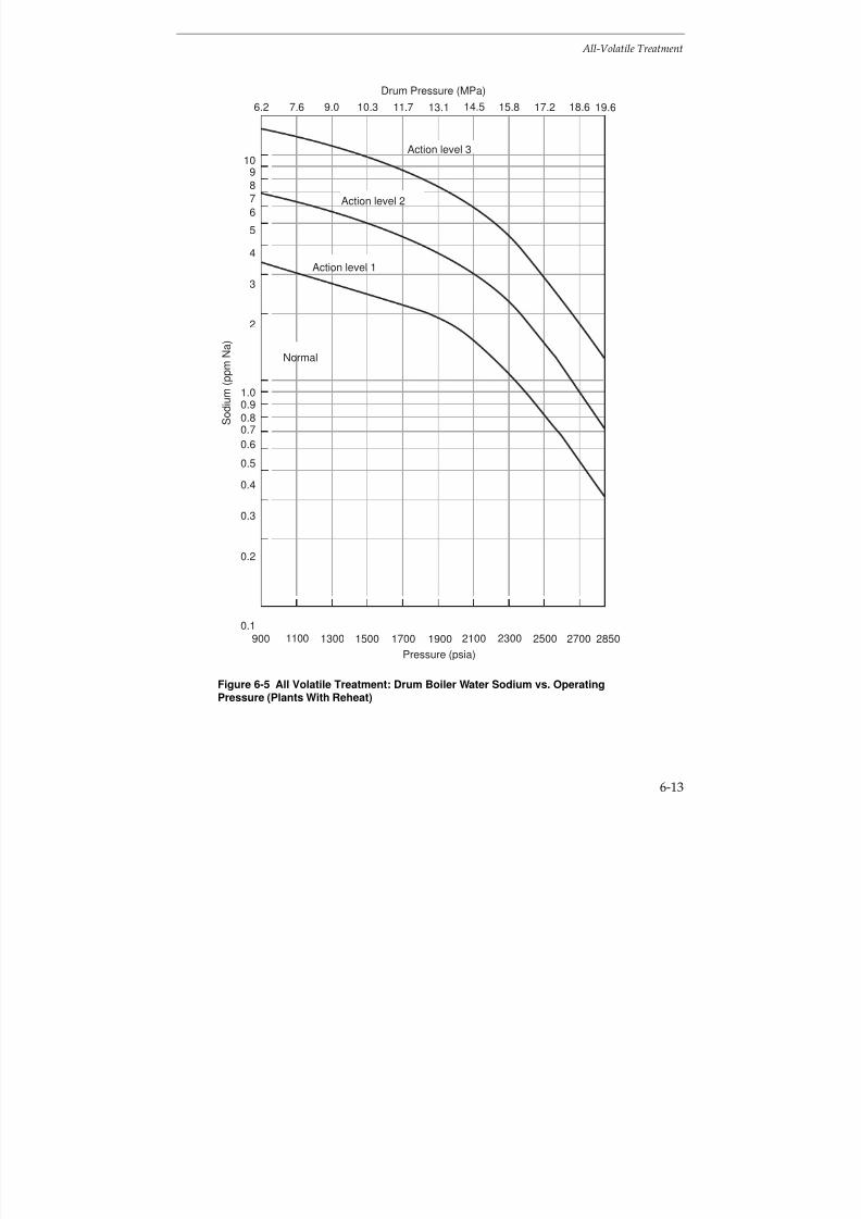
7/18/2019 EPRI Start Up, Lay Up & Shut Down Guidelines for Chemist
http://slidepdf.com/reader/full/epri-start-up-lay-up-shut-down-guidelines-for-chemist 159/256
All-Volatile Treatment
6-13
Action level 3
Normal
10
8
7
2
6
5
4
3
9
S o d i u m ( p
p m N
a )
1500 19001100 17001300
Pressure (psia)
900 27002300 285025002100
Action level 1
Action level 2
1.0
0.80.7
0.2
0.6
0.5
0.4
0.3
0.9
0.1
11.7 13.19.06.2 17.2 19.614.57.6 10.3 15.8 18.6
Drum Pressure (MPa)
Figure 6-5 All Volatile Treatment: Drum Boiler Water Sodium vs. OperatingPressure (Plants With Reheat)

7/18/2019 EPRI Start Up, Lay Up & Shut Down Guidelines for Chemist
http://slidepdf.com/reader/full/epri-start-up-lay-up-shut-down-guidelines-for-chemist 160/256
All-Volatile Treatment
6-14
Pressure (psia)
1300 1700700 15001100600 2500 28502100 270023001900900
C h l o r i d e ( p p m C
l )
Actionlevel 2
Normal
Actionlevel 1
Action level 3
0.10
0.080.07
0.02
0.06
0.05
0.04
0.03
0.09
0.01
1.0
0.80.7
0.2
0.6
0.5
0.4
0.3
0.9
3.0
2.0
1.5
11.7 13.19.06.2 17.2 19.614.57.6 10.3 15.8 18.64.8
Drum Pressure (MPa)
Figure 6-6 All-Volatile Treatment: Drum Boiler Water Chloride vs. OperatingPressure (Plants With Reheat)

7/18/2019 EPRI Start Up, Lay Up & Shut Down Guidelines for Chemist
http://slidepdf.com/reader/full/epri-start-up-lay-up-shut-down-guidelines-for-chemist 161/256
All-Volatile Treatment
6-15
1.0
0.80.7
0.2
0.6
0.5
0.4
0.3
0.9
Drum Pressure (psia)
3.0
2.0
1.5
1300 1700700 15001100600 2500 28502100 270023001900900
S u l f a t e ( p p m S
O 4
)
Actionlevel 2
Normal
Actionlevel 1
Action level 3
0.10
0.080.07
0.02
0.06
0.05
0.04
0.03
0.09
0.01
11.7 13.19.06.2 17.2 19.614.57.6 10.3 15.8 18.64.8
Drum Pressure (MPa)
Figure 6-7 All-Volatile Treatment: Drum Boiler Water Sulfate vs. OperatingPressure (Plants With Reheat)
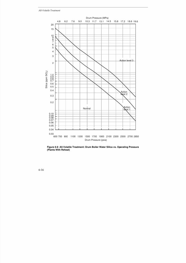
7/18/2019 EPRI Start Up, Lay Up & Shut Down Guidelines for Chemist
http://slidepdf.com/reader/full/epri-start-up-lay-up-shut-down-guidelines-for-chemist 162/256
All-Volatile Treatment
6-16
10
87
2
6
5
4
3
9
Drum Pressure (psia)
0.10
0.080.070.06
0.05
0.04
0.03
0.09
20
15
1300 1700700 15001100600 2500 28502100 270023001900900
S i l i c a ( p p m S
i O 2 )
Actionlevel 2
Normal Actionlevel 1
Action level 3
1.0
0.80.7
0.2
0.6
0.5
0.4
0.3
0.9
11.7 13.19.06.2 17.2 19.614.57.6 10.3 15.8 18.64.8
Drum Pressure (MPa)
Figure 6-8 All-Volatile Treatment: Drum Boiler Water Silica vs. Operating Pressure(Plants With Reheat)

7/18/2019 EPRI Start Up, Lay Up & Shut Down Guidelines for Chemist
http://slidepdf.com/reader/full/epri-start-up-lay-up-shut-down-guidelines-for-chemist 163/256
All-Volatile Treatment
6-17
100
80
70
20
60
50
40
30
90
Drum Pressure (psia)
1300 1700700 15001100600 2500 28502100 270023001900900
C a t i o n C o n d u c t i v i t y - µ S / c m
Normal
Actionlevel 1
Actionlevel 2
Action level 3
10
87
2
6
5
4
3
9
1
11.7 13.19.06.2 17.2 19.614.57.6 10.3 15.8 18.64.8
Drum Pressure (MPa)
Figure 6-9 All-Volatile Treatment: Drum Boiler Water Cation Conductivity vs.Operating Pressure (Plants With Reheat)

7/18/2019 EPRI Start Up, Lay Up & Shut Down Guidelines for Chemist
http://slidepdf.com/reader/full/epri-start-up-lay-up-shut-down-guidelines-for-chemist 164/256
All-Volatile Treatment
6-18
Startup
During off-load conditions, impurities may have been released into the circuit or haveentered from outside, e.g. condenser leaks, CO2 with air ingress. Therefore, duringstartup, it is important to consider the effects of these on the feedwater, boiler waterand steam cation conductivity, silica, sodium, chloride and sulfate concentrationsduring startup. If there is a leak in the reheaters, CO2 and, more importantly, flyash andSO
2, may be drawn in, resulting in acidic condensed steam in the reheaters. There is
some evidence that silica is washed off turbines during shutdown and startup. Oxygenand hydrazine concentrations in the feedwater also require special consideration.Restrictions will need to be applied to these parameters, but some relaxation from thenormal EPRI guideline values may be possible until steady state conditions areachieved.
Section 3 explains how the chemistry curves and action levels can be utilized during
unit startup. Basically, during startups, the initial lower boiler pressure permits boilerwater chemical concentrations to be higher than those at normal unit operatingpressures. Also, the cumulative operating hours per year for which the various actionlevels can be exceeded are twice the values for cycling units, as compared to baseloaded units.
If the boiler has been stored under nitrogen or filled with ammonia and hydrazinesolution, it is necessary to ensure that this is safely vented or disposed.
It is important to prevent high concentrations of oxygen and chloride in the boilerwater, as these can act synergistically and may initiate corrosion
(4). For this reason, the
oxygen concentration of the boiler water should not be allowed to exceed 0.2 ppmduring boiler operation. It is also important to ensure that the pH, cation conductivityand chloride concentration are within the limits given in the EPRI
(1,3) guidelines for
boiler water. It might be possible to eliminate hydrazine in plants with all-ferrousfeedwater heating systems(1) (see Section 7 - Oxygenated Treatment).
Depending on the plant, and the shutdown and layup conditions adopted, several stepswill be required for startup (in addition to filling the boiler following a long shutdownand safely venting the nitrogen, if used). The steps used during startup will be plantspecific and, depending on the practicality, the following stages should be monitored,at least during a trial period:

7/18/2019 EPRI Start Up, Lay Up & Shut Down Guidelines for Chemist
http://slidepdf.com/reader/full/epri-start-up-lay-up-shut-down-guidelines-for-chemist 165/256
All-Volatile Treatment
6-19
Stage during Startup Circuit Monitoring
a) Addition of hydrazine (if used) and
ammonia to the feedwater
pH, cation conductivity and oxygen
b) Additional boiler blowdown pH, cation conductivity, chloride andsuspended corrosion products
c) Care to avoid additional carryover intosteam
Cation conductivity, silica and sodium
At full load, the normal EPRI guideline values given in Figure 6-4 should be achieved.There may be room for relaxation, particularly, as regards silica in steam, duringstartup and the earlier stages of operation and during low load operation, provided theparameters are within the EPRI action levels 1-3, see Figures 6-5 to 6-9. The core
parameters, sodium, cation conductivity and oxygen, given in the EPRI guidelines(1,3)
should be monitored at the condensate pump discharge, condensate polisher outlet (if installed), economizer inlet, boiler water (preferably at downcomer), including pH, andsteam. The normal operating levels, as given in the EPRI guidelines
(1,3), should be
achieved as soon as possible. These are given in Figure 6-4.
A road map showing a scheme for startup of a drum boiler with an all-ferrousfeedwater heating system operating with AVT is given in Figure 6-10. The time taken toachieve the required target values will be plant dependent. This should be determinedfor each unit, used as guidance for subsequent startups and amended in the light of operating experience. The procedure can normally be curtailed for warm and hot starts.
If the high purity feed and boiler water conditions cannot be maintained duringstartup, it may be necessary to resort to another form of chemical conditioning, such asphosphate or caustic treatment. The Selection and Optimization document providesadvice and guidance on the optimum boiler water and feedwater choices for drumunits
(1).
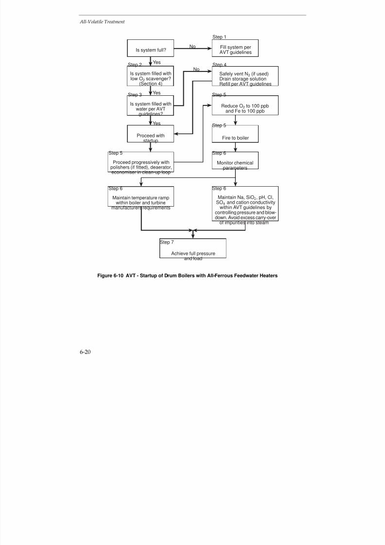
7/18/2019 EPRI Start Up, Lay Up & Shut Down Guidelines for Chemist
http://slidepdf.com/reader/full/epri-start-up-lay-up-shut-down-guidelines-for-chemist 166/256
All-Volatile Treatment
6-20
No
Yes
Step 1
Fill system perAVT guidelines
Fire to boiler
Monitor chemicalparameters
Achieve full pressureand load
Safely vent N2 (if used)Drain storage solutionRefill per AVT guidelines
Reduce O2 to 100 ppband Fe to 100 ppb
Maintain Na, SiO2, pH, Cl,SO4 and cation conductivity
within AVT guidelines bycontrolling pressure and blow-down. Avoid excess carry-over
of impurities into steam
Is system full?
Is system filled withlow O2 scavenger?
(Section 4)
Is system filled withwater per AVT
guidelines?
Proceed withstartup
Maintain temperature rampwithin boiler and turbine
manufacturers requirements
Proceed progressively withpolishers (if fitted), deaerator,economiser in clean-up loop
Step 4
Step 5
Step 5
Step 6
Step 6Step 6
Step 5
Step 3
Step 2
Yes
Yes
No
Step 7
Figure 6-10 AVT - Startup of Drum Boilers with All-Ferrous Feedwater Heaters

7/18/2019 EPRI Start Up, Lay Up & Shut Down Guidelines for Chemist
http://slidepdf.com/reader/full/epri-start-up-lay-up-shut-down-guidelines-for-chemist 167/256
All-Volatile Treatment
6-21
The road map for startup of a drum-type unit operating on AVT with all-ferrousfeedwater heaters, Figure 6-10, can be divided into 7 steps.
The steps are essentially similar to those described in Section 5 for phosphate treatment,except that higher purity water is required for units operating with AVT. Unlike once-through units operating on AVT, described in Section 6.2, control of boiler water puritycan be achieved by blowdown with drum units.
Step 1 - System Stored Dry
If the system has been stored dry (Section 4), it should be filled with water which meetsthe EPRI Guidelines for drum units operating on AVT
(3).
Step 2 - Systems Stored Wet: Low Oxygen Scavenger
If the system has been stored using the low oxygen scavenger procedure (Section 4.8),
the boiler can be fired immediately.Step 3 - System Stored Wet: Excess Ammonia and Hydrazine
If the system has been stored wet with a surplus of ammonia and hydrazine(Section 4.8), it must be drained under nitrogen and refilled with water meeting theEPRI Guidelines for drum units operating on AVT
(3).
Step 4 - System Stored using Nitrogen
If the system has been filled with nitrogen or filled with water, using a nitrogen cap,the nitrogen must be safely vented and the boiler refilled, if necessary, with water
meeting the EPRI Guidelines for drum units operating on AVT(3)
. Startup of the unit canthen proceed.
Step 5 - Cleanup and Firing Boiler
The following limits for the boiler feedwater are required prior to firing the boiler:
Oxygen < 100 ppb
Iron < 100 ppb
During startup, the levels of corrosion products (iron) can be very high initially and
silica may also be a problem. Achieving these limits is greatly facilitated by usingcondensate polishing (if fitted) (See Section 3). When these limits are attained, the boilercan be fired.
Attainment of the prefiring limits will be more difficult in units not equipped withcondensate polisher and/or filtration equipment. Best control will require closecompliance with the guidelines for unit shutdown and layup.

7/18/2019 EPRI Start Up, Lay Up & Shut Down Guidelines for Chemist
http://slidepdf.com/reader/full/epri-start-up-lay-up-shut-down-guidelines-for-chemist 168/256
All-Volatile Treatment
6-22
Step 6 - Monitoring
After firing the boiler, monitoring must be fully implemented, both for chemistryparameters, and to ensure that temperature ramps are maintained according to the boiler and turbine manufacturer’s specifications.
During startup, the concentration vs. pressure curves can be utilized to control sodium,silica, chloride and sulfate (for examples see Figures 6-5 to 6-9). Boiler pressure shouldremain at reduced levels such that these limits are maintained before pressure can beincreased to the next stage. Maximum use of blowdown and condensate polishing (if available) will minimize startup times.
During startup, any chemical excursions must be dealt with quickly and effectively.Increases in feedwater sodium and cation conductivity may indicate contaminationfrom the makeup system, contamination from chemical cleaning operations, condensatepolisher malfunction or condenser leakage. The source must be found and the problem
corrected at once. Excursions affecting (lowering) boiler water pH must be correctedimmediately by feeding trisodium phosphate or 1-2 ppm of sodium hydroxide. Avoidexcess carryover of boiler water impurities into the steam.
Effects of cycle contamination are magnified at startup due to relatively low flow ratesfor condensate, feedwater and steam. Cation conductivity may increase as a result of air ingress due to either aeration of water during the shutdown period or air in-leakageduring startup. The change to boiler water chemistry will be minimal compared tocontamination involving the makeup system, chemical cleaning activities, condensatepolishers or condenser leaks.
Step 7 - Full LoadFull load can be achieved when chemical limits are within the EPRI Guidelines fordrum boilers operating on AVT
(3).
Shutdown
Information is given in Section 4 on shutdown (see Figure 4-8) and below for variousplanned shutdown conditions:
Short shutdown (overnight/weekend) - No change to chemical conditions, leave plantpressurized.
Intermediate shutdown (weekend-week) - Leave plant pressurized or store the boilerunder nitrogen.
Long shutdown (longer than 1 week) - Drain the boiler under nitrogen or blowdownfrom high temperature (e.g. 130°C, 266°F) and maintain the boiler, superheaters andreheaters dry. Continue as described under “Layup”.

7/18/2019 EPRI Start Up, Lay Up & Shut Down Guidelines for Chemist
http://slidepdf.com/reader/full/epri-start-up-lay-up-shut-down-guidelines-for-chemist 169/256
All-Volatile Treatment
6-23
Unplanned shutdowns also occur and, by their very nature, are unpredictable.Therefore, it is difficult to give specific advice, except that, by using circulation,endeavor to achieve the most appropriate conditions given above.
During shutdown, if there is a leak in the reheaters, CO2 and, more importantly, flyash
and SO2, may be drawn in, resulting in acidic condensed steam in the reheaters. Thereis also evidence that silica is washed off turbines during shutdown.
A road map showing a scheme for shutdown of a drum boiler with an all-ferrousfeedwater heating system operating with AVT is given in Figure 6-11. The time taken toachieve stable shutdown conditions will be plant dependent. This should bedetermined for each unit, used as guidance for subsequent repeat operations andamended in the light of operating experience.
Estimate outage length.Use layup appropriatefor duration of outage
No
Step 1
Use short term
layup procedure(Section 4)
Isolate and repairleak, usually allow
continued operation
Step 2
Step 3
Step 3
Step 2
Yes
Consider chemicaltransients due to:-
Orderly shutdown,if polishers utilized,
otherwiseimmediate shutdown
Normal cycling andpeaking operation
Unplanned outage
Yes
Yes
Yes
Yes
Condenser leakfresh water cooling
Condenser leaksea water cooling
Planned outage
Step 4
Step 2
No
No
Step 3
Step 4
Step 5Step 5
Adjust pH >8.0, orderly
shutdown, if polishersutilized, otherwise
immediate shutdown
Yes Chemical intrusionseverely affecting pH
No
Figure 6-11 AVT - Shutdown of Units with Drum Boilers with All-Ferrous andMixed Metallurgy Feedwater Heaters

7/18/2019 EPRI Start Up, Lay Up & Shut Down Guidelines for Chemist
http://slidepdf.com/reader/full/epri-start-up-lay-up-shut-down-guidelines-for-chemist 170/256
All-Volatile Treatment
6-24
The road map for shutdown of a drum-type unit operating on AVT with all-ferrousfeedwater heaters, Figure 6-11, can be divided into 5 steps.
Again, the steps are essentially similar to those described in Section 5 for phosphatetreatment. Unlike once-through boilers operating on AVT, described in Section 6.2,
control of the boiler water purity can be achieved by blowdown with drum boilers.
Step 1 - Normal Cycling or Peaking: Load Reduction or Shutdown
Normal cycling or peaking load reduction or shutdown presumes a short-term layup asdescribed in Section 4.
An orderly reduction of load can be performed for routine cycling operations. Also, anorderly reduction of load or unit shutdown can be performed when contamination isminimal, as determined by chemical monitoring during such transients.
During orderly load reductions, the condensate cycle and boiler chemical limits should
be adjusted to conform with the AVT guidelines for drum units(3).
Particular care should be exercised to prevent oxygen ingress during this period and blowdown should be maintained at an appropriate level to remove contaminants fromthe system.
Step 2 - Outages
Planned or unplanned outages may be short or longterm, depending on systemdemand or the extent of the work required to return the unit to operation. The length of time required for maintenance must be estimated and, depending on this estimate,
short term or longterm layup should be initiated (Section 4). Chemistry should beadjusted prior to shutdown, as indicated in the various options delineated in Section 4.8(Figure 4-8).
An unplanned outage due to an equipment or system failure can be treated as for aplanned outage.
Step 3 - Chemical Transients: Condenser Leak (Fresh Water)
For condenser leaks with fresh, relatively low dissolved solids cooling water, the leakcan generally be isolated and repaired, while the unit is still operational under reducedload (divided water box) or if the condensate polishing plant (if fitted) maintains thefeedwater quality.
Step 4 - Chemical Transients: Condenser Leaks (Sea Water)
Serious damage can occur to units within a short period of time with intrusion of seawater. Without condensate polishing, the boiler must be shutdown immediately upon
7/18/2019 EPRI Start Up, Lay Up & Shut Down Guidelines for Chemist
http://slidepdf.com/reader/full/epri-start-up-lay-up-shut-down-guidelines-for-chemist 171/256
All-Volatile Treatment
6-25
identifying a significant condenser leak. The addition of trisodium phosphate or 1-2ppm of sodium hydroxide may also be required as the boiler water pH drops.
With condensate polishing (if fitted), the unit can generally be shut down in an orderlyfashion, especially, if the polishers are of the deep bed type. With deep bed polishers, it
is prudent to maintain one or more vessels in the hydrogen form for added protectionagainst condenser leakage.
Powdered resin condensate polishers have less capability for removal of dissolvedimpurities than deep bed polishers. If the leak is small, the use of powdered resinsystems may permit an orderly unit shutdown.
Chemical monitoring is especially important when a sea water leak is suspected. Boilerwater pH is critical, and sodium and cation conductivity will assist in estimating theextent of the leak.
In any event, the unit should be shutdown to repair the condenser leak. Depending on
an evaluation of the cycle chemistry, shut down will be immediate or orderly, asoutlined above.
Substantial intrusion of sea water into the boiler will require that the unit is drainedand refilled with water meeting the EPRI Guidelines for drum boilers operating onAVT
(3).
Step 5 - Chemical Transients: Chemical Intrusion
Some of the many causes of chemical intrusion (in addition to condenser leakage)include:
Makeup water system malfunction
Polisher leakage
— Poor regeneration
— Acid or caustic contamination
Chemical cleaning residue; acid, caustic, other
Maintenance chemicals and preservatives
Silica from flyash or other contaminants from maintenance activities
Minor chemical intrusions can be controlled by employment of idle condensatepolishers, if available.
More serious chemical intrusions may affect (lower) the boiler water pH, necessitatingadjustment of boiler water pH through the addition of trisodium phosphate or 1-2 ppm

7/18/2019 EPRI Start Up, Lay Up & Shut Down Guidelines for Chemist
http://slidepdf.com/reader/full/epri-start-up-lay-up-shut-down-guidelines-for-chemist 172/256
All-Volatile Treatment
6-26
sodium hydroxide. If these treatments are unsuccessful, the unit must be shut down(orderly with polishers, immediate without polishers) if the pH falls below 8 (Figure6-4). The unit then requires careful inspection to determine possible damage, and thenecessity for repair and possible chemical cleaning prior to restart.
Intrusion of chemical contamination requires immediate unit shutdown, draining andflushing the unit. Inspection of critical areas of the system (boiler, superheater, turbine,etc) should be performed to assess the effects of chemical intrusion on the system.Chemical cleaning of the boiler, superheater and turbine may be required, dependingon the results of the inspection. Equipment repairs may be required. In such case, along term layup will be required. (See Section 4.)
During emergency shutdowns, such as for major sea water leaks and extensivechemical contamination, immediate unit shutdown is required. Therefore, little can bedone to adjust cycle chemistry during shutdown, since rapid action is required. Duringsuch occasions, the unit should be drained, flushed and inspected to assess damage, as
outlined previously. Restarting the unit will be contingent upon this inspection, as willlayup provisions.
Cycling and Peaking
As an aid to planning and obtaining optimum conditions, it is important to know asaccurately as possible, the frequency and duration of cycling and peaking, the noticegiven and the variation of load patterns.
Essentially, cycling and peaking plants should operate according to the outline givenabove for startup, load changes and shutdown.
Layup
Layup procedures are presented in Section 4, and a road map suitable for units withdrum boilers operating on AVT is depicted in Figure 4-8.
Store the boiler under nitrogen or, if blowdown from a high temperature, maintain the boiler, superheaters and reheaters dry. Possibly dehumidify the feedwater heaters orallow them to remain wet. Avoid air ingress into the feedwater heaters. Monitoroxygen and pH, and nitrogen and moisture, as appropriate. It is also possible to storethe boiler filled with a solution containing ammonia and hydrazine.
The layup conditions are going to be dependent on the method of layup chosen. Thisshould be determined for each unit and each method of layup used. The informationobtained should be used as guidance for subsequent repeat operations and amended inthe light of operating experience.
7/18/2019 EPRI Start Up, Lay Up & Shut Down Guidelines for Chemist
http://slidepdf.com/reader/full/epri-start-up-lay-up-shut-down-guidelines-for-chemist 173/256
All-Volatile Treatment
6-27
6.4 DRUM UNITS WITH MIXED METALLURGY FEEDWATER HEATING
SYSTEMS
EPRI(5)
has recently produced a report on the State-of-Knowledge of Copper in FossilPlant Cycles as the first stage of the “Program Copper” project. This was in response to
a demand from members, particularly in the US, for improved performance of powerplants containing copper alloys. Traditionally, these have been widely used incondensers, but, in some plants, brass and/or cupro-nickel have also been used for heatexchange surfaces in low and high pressure feedwater heaters. Copper released fromfeedwater heaters deposits in the boiler, increasing the locations where impurities canconcentrate on boiler waterwalls. Thick deposits can lead to overheating and thepresence of copper in deposits complicates chemical cleaning.
Copper in high pressure boilers can be carried over into the steam and deposited inhigh pressure turbines, where even as little as 1 kg can reduce the output capacity of the turbine by 1 MW. This is particularly true for plants operating at more than 2400 psi(16.6 MPa) and is exacerbated further by increasing pressure. The presence of oxygenand the absence of reducing conditions in the feedwater during all periods of operationand shutdown is the main cause of copper transport round the circuit.
It is worth reiterating that startups are generally considered to be the periods of maximum copper transport activity in the cycle. This relates directly to the feedwatersystem not being protected during shutdown periods, i.e. that a reducing environment(ORP < 0mV) is not maintained. Air in-leakage into the LP feedwater heating circuitsincreases the growth of non-protective copper oxides and copper transport. The EPRI“Guiding Principles” for successful operation of units with copper alloys
(5) are:
Keep feedwater copper levels at guideline values (< 2 ppb at the economizer inlet)during normal operation.
Establish conditions which favor cuprous oxide (Cu2O) rather than cupric oxide(CuO) under all operating conditions.
Maintain reducing chemistry (oxidizing-reducing potential, ORP < 0mV) at alltimes, including shutdown and startup.
Control feedwater pH in the range 8.8-9.1.
Implement shutdown procedures and layup programs which effectively minimizecopper transport activity upon return to service.
Consider volatility effects in controlling drum pressure; if possible, maximizeoperating pressure in the range of 2400-2500 psi (16.5-17.2 MPa) and avoid over-pressure operation above this range.
7/18/2019 EPRI Start Up, Lay Up & Shut Down Guidelines for Chemist
http://slidepdf.com/reader/full/epri-start-up-lay-up-shut-down-guidelines-for-chemist 174/256
All-Volatile Treatment
6-28
Current Guidelines
The current guidelines for drum boilers with mixed Fe-Cu metallurgy feedwatersystems are given in Figure 6-4 for reheat plants, including the “core” parameters. Thenormal limits and three action levels for sodium, chloride, sulfate, silica and cation
conductivity in boiler water are given in Figures 6-5 to 6-9 for a range of operatingpressures. Except for pH, oxygen, TOC, iron and copper, the limits for non-reheat plantare generally higher by a factor of two. They are not reproduced here and referenceshould be made to the original documents
(1,3).
Startup
During off-load conditions, impurities may have been released into the circuit or haveentered from outside, e.g. condenser leaks, CO2, with air ingress. Therefore, duringstartup it is important to consider the effects of these on the feedwater, boiler water andsteam cation conductivity, silica, sodium, chloride and, sulfate concentrations. If there
is a leak in the reheaters, CO 2 and, more importantly, flyash and SO2, may be drawn in,resulting in acidic condensed steam in the reheaters. There is some evidence that silicais washed off turbines during shutdown and startup. Oxygen, hydrazine and copperconcentrations in the feedwater and copper concentrations of the steam will alsorequire special consideration, since the presence of oxidizing conditions increase therelease and transport of copper around the circuit.
If the boiler has been stored under nitrogen or filled with ammonia and hydrazinesolution, it is necessary to ensure that this is safely vented or disposed.
It is important to prevent high concentrations of oxygen and chloride in the boilerwater, as these can act synergistically and may initiate corrosion. For this reason, theoxygen concentration of the boiler water should not be allowed to exceed 0.2 ppmduring boiler operation. The presence of oxygen also assists the transport of copper intothe steam, increasing the risk of deposition in the superheater and high pressureturbine. It is also important to ensure that the pH, cation conductivity and chlorideconcentration are within the limits given in the EPRI
(1,3) guidelines for boiler water.
Hydrazine (or volatile reducing agents) should not be eliminated from plants withmixed Fe-Cu feedwater heating systems.
Depending on the plant, and the shutdown and layup conditions adopted, several steps
will be required for startup (in addition to filling the boiler following a long shutdownand safely venting the nitrogen, if used). The steps used during startup will be plantspecific and, depending on the practicality, the following stages should be monitored,at least during a trial period:
Stage during Startup Circuit Monitoring
a) Addition of hydrazine and ammonia to pH, cation conductivity, oxygen and
7/18/2019 EPRI Start Up, Lay Up & Shut Down Guidelines for Chemist
http://slidepdf.com/reader/full/epri-start-up-lay-up-shut-down-guidelines-for-chemist 175/256
All-Volatile Treatment
6-29
the feedwater copper
b) Additional boiler blowdown pH, cation conductivity, chloride andsuspended corrosion products
c) Care to avoid additional carryover into
steam
Cation conductivity, silica, sodium and
copper
At full load, the normal EPRI guidelines values given in Figure 6-4 should be achieved.There may be room for relaxation, particularly, as regards silica in steam, duringstartup and the earlier stages of operation and during low load operation, provided theparameters are within the EPRI action levels 1-3, see Figures 6-5 to 6-9. The coreparameters, sodium, cation conductivity and oxygen given in the EPRI
(1,3) guidelines
should be monitored at the condensate pump discharge, condensate polisher outlet (if installed), economizer inlet, boiler water (preferably at downcomer), including pH, andsteam, including copper. The normal operating levels, as given in the EPRI
(1,3)
guidelines, should be achieved as soon as possible. These are given in Figure 6-4.
A road map showing a scheme for startup of a drum boiler with mixed Fe-Cufeedwater heating system operating with AVT is given in Figure 6-12. The time taken toachieve the required target values will be plant dependent. This should be determinedfor each unit, used as guidance for subsequent startups, and amended in the light of operating experience. The procedure can normally be curtailed for warm and hot starts.
The road map, Figure 6-12, can be divided into 7 steps.
Section 3 explains how the chemistry curves and action levels can be utilized duringunit startup. Basically, during startups, the initial lower boiler pressure permits boilerwater chemical concentrations to be higher than those at normal unit operatingpressures. Also, the cumulative operating hours per year for which the various actionlevels can be exceeded are twice the values for cycling units, as compared to baseloaded units.
If the high purity feed and boiler water conditions can not be maintained duringstartup, it may be necessary to resort to another form of chemical conditioning, such asphosphate or caustic treatment. The Selection and Optimization document providesadvice and guidance on the optimum boiler water and feedwater choices for drumunits
(1).
The steps are essentially similar to those described in Section 5 for phosphate treatment,except that higher purity water is required for units operating with AVT. Unlike once-through units operating on AVT, described in Section 6.2, control of boiler water puritycan be achieved by blowdown with drum units. However, compared with units withall-ferrous feedwater heating systems described in Section 6.3, additionalconsiderations are required for units with mixed Fe-Cu feedwater heaters. To reducethe risk of copper corrosion and transport, the ingress of oxygen must be minimized

7/18/2019 EPRI Start Up, Lay Up & Shut Down Guidelines for Chemist
http://slidepdf.com/reader/full/epri-start-up-lay-up-shut-down-guidelines-for-chemist 176/256
All-Volatile Treatment
6-30
and chemically reducing conditions must be maintained during all periods of operation, shutdown and layup.
No
Yes
Step 1
Fill system perAVT guidelines
Fire to boiler
Monitor chemicalparameters
Achieve full pressureand load
Safely vent N2 (if used)Drain storage solutionRefill per AVT guidelines
Add N2H4, if necessary.Reduce O2 to 100 ppb, Fe
to 100 ppb, Cu to 10 ppb
Maintain Cu, Na, SiO2, pH, Cl,SO4 and cation conductivity
within AVT guidelines bycontrolling pressure and blow-down. Avoid excess carryover
of impurities into steam
Is system full?
Is system filled withlow O2 scavenger?
(Section 4)
Is system filled withwater per AVT
guidelines?
Proceed withstartup
Maintain temperature rampwithin boiler and turbine
manufacturers requirements
Proceed progressively withpolishers (if fitted), deaerator,economizer in cleanup loop
Step 4
Step 5
Step 5
Step 6
Step 6Step 6
Step 5
Step 3
Step 2
Yes
Yes
No
Step 7
Figure 6-12 AVT - Startup of Drum Boilers with Mixed Metallurgy FeedwaterHeaters
For ease of reference, full details of the steps for the startup of drum units with mixedFe-Cu feedwater heating systems, operating on AVT, are given below:
7/18/2019 EPRI Start Up, Lay Up & Shut Down Guidelines for Chemist
http://slidepdf.com/reader/full/epri-start-up-lay-up-shut-down-guidelines-for-chemist 177/256
All-Volatile Treatment
6-31
Step 1 - System Stored Dry
If the system has been stored dry (Section 4), it should be filled with water which meetsthe EPRI Guidelines for drum units operating on AVT (3).
Step 2 - Systems Stored Wet: Low Oxygen Scavenger
If the system has been stored using the low oxygen scavenger procedure (Section 4.8),the boiler can be fired immediately.
Step 3 - System Stored Wet: Excess Ammonia and Hydrazine
If the system has been stored wet with a surplus of ammonia and hydrazine (Section 4),it must be drained under nitrogen and refilled with water meeting the EPRI Guidelinesfor drum units operating on AVT
(3).
Step 4 - System Stored using Nitrogen
If the system has been filled with nitrogen or filled with water, using nitrogen capping,the nitrogen must be safely vented and the boiler refilled, if necessary, with watermeeting the EPRI Guidelines for drum units operating on AVT
(3). Startup of the unit can
then proceed.
Step 5 - Cleanup and Firing Boiler
The following limits for the boiler feedwater are required prior to firing the boiler:
Oxygen < 100 ppb
Iron < 100 ppbCopper < 10 ppb
During startup, the levels of corrosion products (iron and copper) can be very highinitially and silica may also be a problem. Achieving these limits is greatly facilitated by using condensate polishing (See Section 3). When these limits are attained, the boilercan be fired.
Attainment of the prefiring limits will be more difficult in units not equipped withcondensate polisher and/or filtration equipment. Best control will require closecompliance with the guidelines for unit shutdown and layup.
Step 6 - Monitoring
After firing the boiler, monitoring must be fully implemented, both for chemistryparameters, and to ensure that temperature ramps are maintained according to the boiler and turbine manufacturer’s specifications.

7/18/2019 EPRI Start Up, Lay Up & Shut Down Guidelines for Chemist
http://slidepdf.com/reader/full/epri-start-up-lay-up-shut-down-guidelines-for-chemist 178/256
All-Volatile Treatment
6-32
During startup, the concentration vs. pressure curves can be utilised to control sodium,silica, chloride and sulfate (for examples see Figures 6-5 to 6-9). Boiler pressure shouldremain at reduced levels such that these limits are maintained before pressure can beincreased to the next stage. Maximum use of blowdown and condensate polishing (if available) will minimize startup times.
During startup, any chemical excursions must be dealt with quickly and effectively.Increases in feedwater sodium and cation conductivity may indicate contaminationfrom the makeup system, contamination from chemical cleaning operations, condensatepolisher malfunction or condenser leakage. The source must be found and the problemcorrected at once. Excursions affecting (lowering) boiler water pH must be correctedimmediately by feeding trisodium phosphate or 1-2 ppm of sodium hydroxide.
Effects of cycle contamination are magnified at startup due to relatively low flow ratesfor condensate, feedwater and steam. Cation conductivity may increase as a result of air ingress due to either aeration of water during the shutdown period or air in-leakage
during startup. The change to boiler water chemistry will be minimal compared tocontamination involving the makeup system, chemical cleaning activities, condensatepolishers or condenser leaks.
Avoid excessive carryover of boiler water impurities into the steam. This includescopper, whose transport can be minimized by avoiding ingress of oxygen andmaintaining chemically reducing conditions.
Step 7 - Full Load
Full load can be achieved when chemical limits are within the EPRI Guidelines for
drum boilers operating on AVT
(3)
.
Shutdown
Information is given in Section 4 on shutdown (see Figure 4-8) and below for variousplanned shutdown conditions:
Short shutdown (overnight/weekend) - No change to chemical conditions, leave plantpressurized, avoid air ingress to the feedheaters.
Intermediate shutdown (weekend-week) - Leave plant pressurized or store the boiler
under nitrogen. Avoid air ingress to the feedwater heaters.
Long shutdown (longer than 1 week) - Drain the boiler under nitrogen or blowdownfrom high temperature (e.g. 130°C) and maintain the boiler, superheaters and reheatersdry. Continue as described under “Layup”.

7/18/2019 EPRI Start Up, Lay Up & Shut Down Guidelines for Chemist
http://slidepdf.com/reader/full/epri-start-up-lay-up-shut-down-guidelines-for-chemist 179/256
All-Volatile Treatment
6-33
Unplanned shutdowns also occur and, by their very nature, are unpredictable.Therefore, it is difficult to give specific advice, except that, by using circulation,endeavor to achieve the most appropriate conditions given above.
During shutdown. if there is a leak in the reheaters, CO2 and, more importantly, flyash
and SO2, may be drawn in, resulting in acidic condensed steam in the reheaters. Thereis also evidence that silica is washed off turbines during shutdown.
A road map showing a scheme for shutdown of a drum boiler with a mixed Fe-Cu-feedwater heating system operating with AVT is given in Figure 6-11. The time taken toachieve stable shutdown conditions will be plant dependent. This should bedetermined for each unit, used as guidance for subsequent repeat operations andamended in the light of operating experience.
The road map for shutdown of a unit with a drum boiler operating on AVT with mixedmetallurgy feedwater heaters, Figure 6-11, can be divided into 5 steps.
Again, the steps are essentially similar to those described in Section 5 for phosphatetreatment, except that higher purity water is required for units operating with AVT.Unlike once-through boilers operating on AVT, described in Section 6.2, control of the boiler water purity can be achieved by blowdown with drum boilers. However,compared with units with all-ferrous feedwater heating systems described in Section6.3, additional considerations are required for units with mixed Fe-Cu feedwaterheaters. To reduce the risk of copper corrosion and transport, the ingress of oxygenmust be minimized and chemically reducing conditions must be maintained.
Step 1 - Normal Cycling or Peaking: Load Reduction or Shutdown
Normal cycling or peaking load reduction or shutdown presumes a short term layup asdescribed in Section 4.
An orderly reduction of load can be performed for routine cycling operations. Also, anorderly reduction of load or unit shutdown can be performed when contamination isminimal, as determined by chemical monitoring during such transients.
During orderly load reductions, the condensate cycle and boiler chemical limits should be adjusted to conform with the AVT guidelines for drum units
(3).
Particular care should be exercised to prevent oxygen ingress during this period tominimize pickup of copper. Blowdown should be maintained at an appropriate level toremove contaminants from the system.
7/18/2019 EPRI Start Up, Lay Up & Shut Down Guidelines for Chemist
http://slidepdf.com/reader/full/epri-start-up-lay-up-shut-down-guidelines-for-chemist 180/256
All-Volatile Treatment
6-34
Step 2 - Outages
Planned or unplanned outages may be short or longterm, depending on systemdemand or the extent of the work required to return the unit to operation. The length of time required for maintenance must be estimated and, depending on this estimate,
short term or longterm layup should be initiated (Section 4). Chemistry should beadjusted prior to shutdown, as indicated in the various options deliniated in Section 4.8(Figure 4-8).
An unplanned outage due to an equipment or system failure can be treated as for aplanned outage.
Step 3 - Chemical Transients: Condenser Leak (Fresh Water)
For condenser leaks with fresh, relatively low dissolved solids cooling water, the leakcan generally be isolated and repaired, while the unit is still operational under reduced
load (divided water box) or if the condensate polishing plant (if fitted) maintains thefeedwater quality.
Step 4 - Chemical Transients: Condenser Leaks (Sea Water)
Serious damage can occur to units within a short period of time with intrusion of seawater. Without condensate polishing, the boiler must be shutdown immediately uponidentifying a significant condenser leak. The addition of trisodium phosphate or 1-2ppm of sodium hydroxide may also be required as the boiler water pH drops.
With condensate polishing (if fitted), the unit can generally be shut down in an orderlyfashion, especially, if the polishers are of the deep bed type. With deep bed polishers, itis prudent to maintain one or more vessels in the hydrogen form for added protectionagainst condenser leakage.
Powdered resin condensate polishers have less capability for removal of dissolvedimpurities than deep bed polishers. If the leak is small, the use of powdered resinsystems may permit an orderly unit shutdown.
Chemical monitoring is especially important when a sea water leak is suspected. Boilerwater pH is critical, and sodium and cation conductivity will assist in estimating theextent of the leak.
In any event, the unit should be shut down to repair the condenser leak. Depending onan evaluation of the cycle chemistry, shutdown will be immediate or orderly, asoutlined above.
Substantial intrusion of sea water into the boiler will require that the unit is drainedand refilled with water meeting the EPRI Guidelines for drum boilers operating onAVT
(3).
7/18/2019 EPRI Start Up, Lay Up & Shut Down Guidelines for Chemist
http://slidepdf.com/reader/full/epri-start-up-lay-up-shut-down-guidelines-for-chemist 181/256
All-Volatile Treatment
6-35
Step 5 - Chemical Transients: Chemical Intrusion
Some of the many causes of chemical intrusion (in addition to condenser leakage)include:
Makeup water system malfunction
Polisher leakage
Poor regeneration
Acid or caustic contamination
Chemical cleaning residue; acid, caustic, other
Maintenance chemicals and preservatives
Silica from flyash or other contaminants from maintenance activities
Minor chemical intrusions can be controlled by employment of idle condensatepolishers, if available.
More serious chemical intrusions may affect (lower) the boiler water pH, necessitatingadjustment of boiler water pH through the addition of trisodium phosphate or 1-2 ppmsodium hydroxide. If these treatments are unsuccessful, the unit must be shut down(orderly with polishers, immediate without polishers). The unit then requires carefulinspection to determine possible damage, and the necessity for repair and possiblechemical cleaning prior to restart.
Intrusion of chemical contamination requires immediate unit shutdown, draining andflushing the unit. Inspection of critical areas of the system (boiler, superheater, turbine,etc) should be performed to assess the effects of chemical intrusion on the system.Chemical cleaning of the boiler, superheater and turbine may be required, dependingon the results of the inspection. Equipment repairs may be required. In such case, along term layup will be required. (See Section 4.)
During emergency shutdowns, such as for major sea water leaks and extensivechemical contamination, immediate unit shutdown is required. Therefore, little can bedone to adjust cycle chemistry during shutdown, since rapid action is required. Duringsuch occasions, the unit should be drained, flushed and inspected to assess damage, as
outlined previously. Restarting the unit will be contingent upon this inspection, as willlayup provisions.
7/18/2019 EPRI Start Up, Lay Up & Shut Down Guidelines for Chemist
http://slidepdf.com/reader/full/epri-start-up-lay-up-shut-down-guidelines-for-chemist 182/256
All-Volatile Treatment
6-36
Cycling and Peaking
As an aid to planning and obtaining optimum conditions, it is important to know asaccurately as possible, the frequency and duration of cycling and peaking, the noticegiven and the variation of load patterns.
Essentially, cycling and peaking plant should operate according to the outline givenabove for startup, load changes and shutdown.
Layup
Layup procedures are presented in Section 4, and a road map suitable for drum boilersoperating on AVT is depicted in Figure 4-8.
Store the boiler under nitrogen or, if blowdown from a high temperature, maintain the boiler, superheaters and reheaters dry. Possibly dehumidify the feedwater heaters or
allow them to remain wet. Avoid air ingress to the feedwater heaters, as this leads tothe increased corrosion of copper alloys, particularly in the presence of ammonia.Monitor oxygen and pH, and nitrogen and moisture, as appropriate. It is also possibleto store the boiler filled with a solution containing ammonia and hydrazine. Avoidcontact of solutions with high ammonia concentrations with the copper alloys.
The layup conditions are going to be dependent on the method of layup chosen. Thisshould be determined for each unit and each method of layup used. The informationobtained should be used as guidance for subsequent repeat operations and amended inthe light of operating experience.
6.5 REFERENCES
1. Selection and Optimization of Boiler and Feedwater Treatment for Fossil Plants. ElectricPower Research Institute, Palo Alto, Calif. EPRI TR-105040. March 1997
2. Interim Consensus Guidelines on Fossil Plant Cycle Chemistry. Electric Power ResearchInstitute, Palo Alto, Calif. EPRI CS-4629. June 1986
3. Cycle Chemistry Guidelines for Fossil Plants: All Volatile Treatment. Electric PowerResearch Institute, Palo Alto, Calif. EPRI TR-105041. April 1996
4. G. M. W. Mann and R. Garnsey, “Waterside Corrosion Associated with Two-ShiftBoiler Operation on All-Volatile Treatment Chemistry.” Corrosion 79 Conference.Materials Performance, October 1980, pp 32-38
5. State-of-Knowledge of Copper in Fossil Plant Cycles. Electric Power Research Institute,Palo Alto, Calif. EPRI TR-108460, September 1997

7/18/2019 EPRI Start Up, Lay Up & Shut Down Guidelines for Chemist
http://slidepdf.com/reader/full/epri-start-up-lay-up-shut-down-guidelines-for-chemist 183/256
EPRI L icensed M aterial
6-1
6
ALL-VOLATILE TREATMENT
6.1 INTRODUCTION
All-volatile treatment must be used for once-through units, to avoid deposition of non-volatile compounds in the boiler water/steam circuit. With the “traditional” form of all-volatile treatment (AVT), ammonia and hydrazine is added to the feedwater toprovide chemical conditions that protect the feedwater heaters, boiler, superheaters,reheaters and turbine against corrosion, without further chemical additions.
An alternative chemical treatment for once-through units is oxygenated treatment (OT -see Section 7), where instead of hydrazine, oxygen is added in addition to theammonia. An intermediate form of conditioning is also being used, where onlyammonia, without hydrazine or oxygen, is added to the feedwater. With all threealternatives, the degree of protection against corrosion provided by the chemicaladditives is strictly limited. Therefore, it is essential to maintain high purity feedwaterand to prevent the ingress of impurities, both while on-load and during off-loadconditions.
All-volatile treatment can also be used for units with drum-type boilers, provided highpurity feedwater is available and the buildup of impurities in the boiler water is strictlycontrolled. The absence of a solid alkalizing chemical in the boiler water gives lessprotection against corrosion, but, because there should be lower concentrations of impurities in the boiler water, it also reduces the risk of carrying over boiler water saltsand solid alkalizing chemicals into the steam. If the high purity feed and boiler waterconditions cannot be maintained during startup, operation and shutdown, it may benecessary to resort to another form of chemical conditioning, such as phosphate orcaustic treatment. The Selection and Optimization document provides advice andguidance on the optimum boiler water and feedwater choices for drum units
(1).
Guidance on the use of AVT was given in the EPRI Interim Consensus Guidelines(2)
in1986. Cycle diagrams were provided for once-through and drum-type boilers with allferrous and mixed Fe-Cu metallurgy feedwater heating systems. The normal limits andthree action levels were given for sodium, chloride, sulfate, silica and cationconductivities for feedwater and steam for once-through boilers. A range of pressureswas considered for drum boilers, with and without reheat, with additional pressurecurves for the normal limits and three action levels for sodium, chloride, sulfate and

7/18/2019 EPRI Start Up, Lay Up & Shut Down Guidelines for Chemist
http://slidepdf.com/reader/full/epri-start-up-lay-up-shut-down-guidelines-for-chemist 184/256
EPRI L icensed M aterial
All-Volatile Treatment
6-2
silica in the boiler water. In addition, some general guidance was also included onstartup, cycling and peaking operation.
The AVT guidelines for once-through and drum boilers were revised in 1996(3)
and“core” parameters for a minimum level of instrumentation were given (Table 1-1), in
addition to the comprehensive list of parameters. Guidance was included for all-ferrousand mixed Fe-Cu metallurgy for drum-type boilers, but was restricted to all-ferrousfeedwater heating systems for once-through boilers. Revised guidelines and actionlevels were given and guidance was included on optimizing AVT.
Further minor revisions to the “core” parameters were incorporated in the EPRI reporton Selection and Optimization of Boiler Water and Feedwater Treatment of FossilPlants
(1).
As an aid to planning and obtaining the optimum operating conditions for cycling,startup, shutdown and layup, it is important to know as accurately as possible, what
notice will be given of shutdown, the period of outage and for startup.
6.2 ONCE-THROUGH UNITS
Current Guidelines
In considering cycling, startup, shutdown and layup of units operating on AVT, it isassumed, in accordance with the latest EPRI Cycle Chemistry Guidelines
(3), that the
units with once-through boilers under consideration have condensate polishing plantsand all-ferrous feedwater heating systems. The cycle diagram for all parameters
(including the “core parameters”) is given in Figure 6-1 for once-through unitsoperating with AVT.
Startup
During off-load conditions, deposited impurities may have been released into thecircuit or have entered from outside, e.g. condenser leaks, CO2 with air in-leakage.Therefore, it is important to consider the effects on the feedwater and steam cationconductivity, silica, sodium, chloride and sulfate concentrations during startup. If thereis a leak in the reheaters, CO 2 and, more importantly, flyash and SO2, may be drawn in,resulting in acidic condensed steam in the reheaters. There is some evidence that silica
is washed off turbines during shutdown and startup. Oxygen and hydrazineconcentrations in the feedwater require special consideration. Restrictions will need to be applied to these parameters, but some relaxation from the normal EPRI guidelinevalues should be possible until steady state operating conditions are achieved. It should be possible to eliminate hydrazine entirely, for once-through units with all-ferrousfeedwater heating systems
(1) (see also Section 7 - Oxygenated Treatment).

7/18/2019 EPRI Start Up, Lay Up & Shut Down Guidelines for Chemist
http://slidepdf.com/reader/full/epri-start-up-lay-up-shut-down-guidelines-for-chemist 185/256
EPRI Li censed Mat eri al
Specific conductivitya
Cation conductivity, µS/cma
HP
turbine
LP
turbine
Deaerator
Attemperat
Boiler
LP Condensate
polisher
Makeup
treatment
system
Condensate
storage tank
Condenser
IP
turbine
HP heaters
N (Normal)
Maximum Annual Exposure to
Contaminant Conditions
Targets
Cumulative Hours per Year
Base Load Cycling
1 (Action Level 1)
2 (Action Level 2)
3 (Action Level 3)
—
336 ( 2 weeks)
48 (2 days)
8
1Immediate Shutdown
—
672 (4 weeks)
96 (4 days)
16
2
Hydrazine, ppb
Deaerator Outlet
Parameter
TargetSample N
C < 20 ppb
Oxygen, ppb
Deaerator Inlet
Parameter
TargetSample N
T < 10
Hydrazine, ppb
Low-Pressure Steam (Optional)
ParameterTarget Injection
Dosage
< 20
Air inleakage,
scfm/100 MWe
Air Removal System Exhaust
Parameter
TargetSample N
D ≤ 1
Cation conductivitya
or sodium
Condenser Leak Detection Trays orHotwell Zones (If applicable)
Parameter
Target
Sampl
C
Con
Pa
Sod
Oxy
Tot
•
Cat
µS/
Cation conductivity,
µS/cma
Sodium, ppb
Condensate Polisher Effluent
ParameterTarget
Sample N
Silica, ppb C ≤ 10
C ≤ 0.15
1
> 10
≤ 0.2
2
—
3
—
C ≤ 3 ≤ 6 ≤ 12 > 12CR •
CR • ≤ 0.3 > 0.65
CR •
CR •
Economizer Inlet and Attemperation Water
Parameter Target Sample N
All ferrous metallurgy C 9.2-9.6
1
< 9.2
> 9.6
2
—
3
—
Ammonia D
C
pHa
Consistent with pH
C ≤ 0.15 ≤ 0.2 ≤ 0.3 > 0.65
Iron, ppb
Copper, ppb
Oxygen, ppb
W ≤ 5 > 5 — —
W ≤ 2 > 2 — —
C 1-10 ≤ 15 ≤ 20 > 20
CR •
CR •
Reheat Steam
ParameterTarget
Sample N
Sodium, ppb C ≤ 3
To ta l o rg an ic c arb on , p pb W ≤ 100
Specific conductivitya
T —
Cation conductivity,
µS/cma
C
Silica, ppb T ≤ 10
Chloride, ppb T ≤ 3
Sulfate, ppb T ≤ 3
1
≤ 6
> 100
—
≤ 20
≤ 6
≤ 6
2
≤ 12
—
—
≤ 40
≤ 12
≤ 12
3
> 12
—
—
> 40
> 12
> 12
CR •
CR • ≤ 0.15 ≤ 0.2 ≤ 0.3 > 0.65
N = Normal
1 = Action Level 1
2 = Action Level 2
3 = Action Level 3
Target Values
Legend
C = continuous
S = grab, once per shift
D = grab, once per day
W = grab, once per week
T = troubleshooting and commissioning
Sample Frequency
Footnotes
a = Conductivity and pH measured at 25° C
e = Target values may be adjusted to reflect capabilities of installed equipment
Figure 6-1 Cycle Chemistry Diagram for a Once-Through Unit on All-Volatile Treatment

7/18/2019 EPRI Start Up, Lay Up & Shut Down Guidelines for Chemist
http://slidepdf.com/reader/full/epri-start-up-lay-up-shut-down-guidelines-for-chemist 186/256
All-Volatile Treatment
6-4
Depending on the plant, and the shutdown and layup conditions adopted, several stepswill be required for startup (in addition to filling the boiler following a long shutdownand safely venting the nitrogen, if used). The steps used during startup will be plantspecific and, depending on the practicality, the following stages should be monitored,at least during a trial period:
StageduringStartup CircuitMonitoringa)Circulationviadeaerator pH, ironandcationconductivity b)Circulationviaeconomizer pH, Fe, cationconductivity, oxygenandhydrazinec)Circulationviatheboiler pH, Fe, cationconductivity, silica, sodiumandchlorided)Allowfiring pH, ironandcationconductivity
e)Allowsteamtoturbine pH, ironandcationconductivityf)Turbinetoonethirdload pH, ironandcationconductivityg)Tofullload pH, ironandcationconductivityOnfull load, thenormal EPRIGuidelinesvaluesgiveninFigure6-1shouldbeachieved. Theremayberoomforrelaxation, particularly, asregardssilicainsteam,duringstartup, theearlierstagesofoperationandduringlowloadoperation, providedtheparametersarewithintheEPRIactionlevels1-3. (Notethattheguidelinesarethesameforall operatingpressuresforonce-throughboilers.)Thecoreparameters,sodium, cationconductivityandoxygengivenintheEPRIGuidelinesshouldbemonitoredatthecondensatepumpdischarge, condensatepolisheroutlet, economizerinletandsteam, andalsopH, silicaandiron, ifpossible, atleastduringatrial period.Thenormal operatinglevels, asgivenintheEPRIguidelines, shouldbeachievedassoonaspossible. ThesearegiveninFigure6-1.Aroadmap(decisiontree)showingaschemeforstartupofaonce-throughunitoperatingwithAVTisgiveninFigure6-2. Thetimetakentoachievetherequiredtargetvalueswill beplantdependent. Thisshouldbedeterminedforeachunit, usedasguidanceforsubsequentstartups, andamendedinthelightofoperatingexperience.Theprocedurecanusuallybecurtailedforwarmandhotstarts.Theroadmapforstartupofonce-throughunitsoperatingonAVT, Figure6-2, canbedividedinto7steps.

7/18/2019 EPRI Start Up, Lay Up & Shut Down Guidelines for Chemist
http://slidepdf.com/reader/full/epri-start-up-lay-up-shut-down-guidelines-for-chemist 187/256
All-Volatile Treatment
6-5
No
Yes
Step 1
Fill system perAVT guidelines
Monitor chemicalparameters
Achieve full pressureand load
Safely vent N2 (if used)Refill per AVT guidelines
Maintain Na, SiO2, pH, Cl,SO4 and cation conductivity
within the AVT guidelines
Is system full?
Is system filled withlow O2 scavenger?
(Section 4)
Is system filled withwater per AVT
guidelines?
Proceed withstartup
Maintain temperature rampwithin boiler and turbine
manufacturers requirements
Proceed progressively withthe polishers, deaerator,
economiser in cleanup loop
Step 4
Step 5
Step 5
Step 6
Step 6Step 6
Step 5
Step 3
Step 2
Yes
Yes
No
Step 7
Reduce O2 to 100 ppband Fe to 30 ppb
Fire to boiler
Figure 6-2 Startup of Once-through Units with All-Ferrous Feedwater Heaters
The steps are essentially similar to those described in Section 5 for phosphate treatment,except that for once-through boilers, very high purity water is required for the boiler,as well as for feedwater. Control of boiler water purity cannot be achieved by blowdown, as is the case with drum boilers, and the absence of the “reservoir” of the boiler and a steam separation stage in once-through boilers, means that the acceptablelevel of impurities is much less than for drum boilers.
7/18/2019 EPRI Start Up, Lay Up & Shut Down Guidelines for Chemist
http://slidepdf.com/reader/full/epri-start-up-lay-up-shut-down-guidelines-for-chemist 188/256
All-Volatile Treatment
6-6
Step 1 - System Stored Dry
If the system has been stored dry (Section 4), it should be filled with water which meetsthe EPRI Guidelines for once-through units operating on AVT (3).
Step 2 - Systems Stored Wet: Low Oxygen Scavenger
If the system has been stored using the low oxygen scavenger procedure (Section 4), the boiler can be fired immediately.
Step 3 - System Stored Wet: Excess Ammonia and Hydrazine
If the system has been stored wet with a surplus of ammonia and hydrazine (Section 4),it must be drained under nitrogen and refilled with water meeting the EPRI Guidelinesfor once-through units operating on AVT
(3).
Step 4 - System Stored using Nitrogen
If the system has been filled with nitrogen or filled with water, using nitrogen capping,the nitrogen must be safely vented and the boiler refilled, if necessary, with watermeeting the EPRI Guidelines for once-through units operating on AVT
(3). Startup of the
unit can then proceed.
Step 5 - Cleanup and Firing Boiler
The following limits for the boiler feedwater are required prior to firing the boiler:
Oxygen < 100 ppb
Iron < 30 ppbDuring startup, the levels of corrosion products (iron) can be very high initially andsilica may also be a problem. Achieving these limits is greatly facilitated by usingcondensate polishing (See Section 3). When these limits are attained, the boiler can befired.
Step 6 - Monitoring
After firing the boiler, monitoring must be fully implemented, both for chemistryparameters, and to ensure that temperature ramps are maintained according to the boiler and turbine manufacturer’s specifications.
During startup, any chemical excursions must be dealt with quickly and effectively.Increases in feedwater sodium and cation conductivity may indicate contaminationfrom the makeup system, contamination from chemical cleaning operations, condensatepolisher malfunction or condenser leakage. The source must be found and the problemcorrected at once.
7/18/2019 EPRI Start Up, Lay Up & Shut Down Guidelines for Chemist
http://slidepdf.com/reader/full/epri-start-up-lay-up-shut-down-guidelines-for-chemist 189/256
All-Volatile Treatment
6-7
Step 7 - Full Load
Full load can be achieved when chemical limits are within the EPRI Guidelines foronce-through units operating on AVT(3).
Shutdown
Information is given in Section 4.8 on Shutdown and below for various plannedshutdown conditions.
Short shutdown (overnight/weekend) - No change to chemical conditions, leave plantpressurized. Maintain condensate circulation and deaerator pressure. Raise the pHwhen coming off-load.
Intermediate shutdown (weekend/week) - Leave plant pressurized, raise pH and thehydrazine concentration (if used), when coming off-load.
Long shutdown (longer than 1 week) - Drain under nitrogen or from high temperature(e.g. 130°C) and maintain the boiler, superheaters and reheaters dry. Continue asdescribed under “Layup”.
Unplanned shutdowns also occur and, by their very nature, are unpredictable.Therefore, it is difficult to give specific advice, except that, by using circulation,endeavor to achieve the most appropriate conditions given above.
During shutdown, if there is a leak in the reheaters, CO2 and, more importantly, flyash
and SO2, may be drawn in, resulting in acidic condensed steam in the reheaters. There
is also evidence that silica is washed off turbines during shutdown.
A road map showing a scheme for shutdown of a once-through boiler operating withAVT is given in Figure 6-3. The time taken to achieve stable shutdown conditions will be plant dependent. This should be determined for each unit, as guidance forsubsequent shutdowns and amended in the light of operating experience.
The road map for shutdown of once-through units operating on AVT, Figure 6-3, can be divided into 5 steps.

7/18/2019 EPRI Start Up, Lay Up & Shut Down Guidelines for Chemist
http://slidepdf.com/reader/full/epri-start-up-lay-up-shut-down-guidelines-for-chemist 190/256
All-Volatile Treatment
6-8
Estimate outage length.Use layup appropriatefor duration of outage
No
Step 1
Use short termlayup procedure
(Section 4)
Isolate and repairleak, usually allow
continued operation
Step 2
Step 3
Step 3
Step 2
Yes
Consider chemicaltransients due to:-
Orderly shutdown,if polishers utilized,
otherwiseimmediate shutdown
Normal cycling andpeaking operation
Unplanned outage
Yes
Yes
Yes
Yes
Condenser leakfresh water cooling
Condenser leaksea water cooling
Planned outage
Step 4
Step 2
No
No
Step 3
Step 4
Step 5
Step 5
Orderly shutdown, ifpolishers utilized,
otherwiseimmediate shutdown
YesChemical intrusion
No
Figure 6-3AVT - Shutdown of Once-Through Units with All-Ferrous Feedwater Heaters
The steps are essentially similar to those described in Section 5 for phosphate treatment,except that for once-through boilers, very high purity water is required for the boiler,as well as the feedwater, and control of the boiler water purity cannot be achieved by blowdown.
Step 1 - Normal Cycling or Peaking: Load Reduction or Shutdown
Normal cycling or peaking load reduction or shutdown presumes a short-term layup as
described in Section 4.
An orderly reduction of load can be performed for routine cycling operations. Also, anorderly reduction of load or unit shutdown can be performed when contamination isminimal, as determined by chemical monitoring during such transients.
Step 2 - Outages
7/18/2019 EPRI Start Up, Lay Up & Shut Down Guidelines for Chemist
http://slidepdf.com/reader/full/epri-start-up-lay-up-shut-down-guidelines-for-chemist 191/256
All-Volatile Treatment
6-9
Planned or unplanned outages may be short or long term, depending on systemdemand or the extent of the work required to return the unit to operation. The length of time required for maintenance must be estimated and, depending on this estimate,short term or longterm layup should be initiated (Section 4). Chemistry should beadjusted prior to shutdown, as indicated in the various options delineated in Section 4.8
(Figure 4-8).
An unplanned outage due to an equipment or system failure can be treated as for aplanned outage.
Step 3 - Chemical Transients: Condenser Leaks (Fresh Water)
For condenser leaks with fresh, relatively low dissolved solids cooling water, the leakcan generally be isolated and repaired, while the condensate polishing plant maintainsthe feedwater quality.
Step 4 - Chemical Transients: Condenser Leaks (Sea Water)
Serious damage can occur to units within a short period of time with intrusion of seawater. With condensate polishing, the unit can generally be shut down in an orderlyfashion, especially if the polishers are of the deep bed type. With deep bed polishers, itis prudent to maintain one or more vessels in the hydrogen form for added protectionagainst condenser leakage.
Powdered resin condensate polishers have less capability for removal of dissolvedimpurities than deep bed polishers. If the leak is small, the use of powdered resinsystems may permit an orderly unit shutdown.
Chemical monitoring is especially important when a sea water leak is suspected.Sodium and cation conductivity will assist in estimating the extent of the leak.
In any event, the unit should be shut down to repair the condenser leak. Depending onan evaluation of the cycle chemistry, shutdown will be immediate or orderly, asoutlined above.
Substantial intrusion of sea water into the boiler will require that the unit is drainedand refilled with water meeting the EPRI Guidelines for once-through units operatingon AVT
(3).

7/18/2019 EPRI Start Up, Lay Up & Shut Down Guidelines for Chemist
http://slidepdf.com/reader/full/epri-start-up-lay-up-shut-down-guidelines-for-chemist 192/256
All-Volatile Treatment
6-10
Step 5 - Chemical Transients: Chemical Intrusion
Some of the many causes of chemical intrusion (in addition to condenser leakage)include:
Makeup water system malfunction
Polisher leakage
— Poor regeneration
— Acid or caustic contamination
Chemical cleaning residue; acid, caustic, other
Maintenance chemicals and preservatives
Silica from flyash or other contaminants from maintenance activitiesMinor chemical intrusions can be controlled by employment of idle condensatepolishers, if available.
Intrusion of chemical contamination requires immediate unit shutdown, draining andflushing the unit. Inspection of critical areas of the system (boiler, superheater, turbine,etc) should be performed to assess the effects of chemical intrusion on the system.Chemical cleaning of the boiler, superheater and turbine may be required, dependingon the results of the inspection. Equipment repairs may be required. In such case, along term layup will be required. (See Section 4.)
During emergency shutdowns, such as for major sea water leaks and extensivechemical contamination, immediate unit shutdown is required. Therefore, little can bedone to adjust cycle chemistry during shutdown, since rapid action is required. Duringsuch occasions, the unit should be drained, flushed and inspected to assess damage, asoutlined previously. Restarting the unit will be contingent upon this inspection, as willlayup provisions.
Cycling and Peaking
Special features may be required for once-through units to cycle, such as a turbine bypass (Section 2).
As an aid to planning and obtaining optimum conditions, it is important to know asaccurately as possible, the frequency and duration of cycling and peaking, the noticegiven and the variation of load patterns.
Essentially, cycling and peaking plant should operate according to the outline givenabove for startup, load changes and shutdown.
7/18/2019 EPRI Start Up, Lay Up & Shut Down Guidelines for Chemist
http://slidepdf.com/reader/full/epri-start-up-lay-up-shut-down-guidelines-for-chemist 193/256
All-Volatile Treatment
6-11
Layup
Layup procedures are presented in Section 4 and a road map suitable for once-throughunits operating on AVT is depicted in Figure 4-8.
Store under nitrogen or, if shutdown from a high temperature, maintain the boiler,superheaters and reheaters dry. Possibly dehumidify the feedheaters or allow them toremain wet. Avoid air ingress into the feedheaters. Monitor oxygen and pH, andnitrogen and moisture, as appropriate.
The layup conditions are going to be dependent on the method of layup chosen. Thisshould be determined for each unit and each method of layup used. The informationobtained should then be used as guidance for subsequent repeat operations andamended in the light of operating experience.
6.3 DRUM BOILERS WITH ALL-FERROUS FEEDWATER HEATING
SYSTEMS
In general, the features for the feedwater and steam for units with once-through boilers,also apply to drum boilers. However, these need to be supplemented by additionalconsiderations for the boiler water. Some units with drum boilers may be equippedwith a condensate polishing plant, but many units are not and, therefore, will be moresusceptible to the effects of condenser leaks.
For completeness and ease of reference for AVT, phosphate treatments (Section 5), andcaustic treatment (Section 8), drum boilers with all-ferrous and mixed Fe-Cumetallurgy feedwater heating systems are considered separately in the next twosections.
Current Guidelines
The current guidelines for drum boilers with all-ferrous feedwater heating systems aregiven in Figure 6-4 for units with reheat, including the “core” parameters. The normallimits and three action levels for sodium, chloride, sulfate, silica and cationconductivity in boiler water are given in Figures 6-5 to 6-9 for a range of operatingpressures. The values given for plants without reheat are twice those for plants withreheat, except for pH, oxygen, TOC, iron and copper. They are not reproduced here
and reference should be made to the original documents(1,3)
.
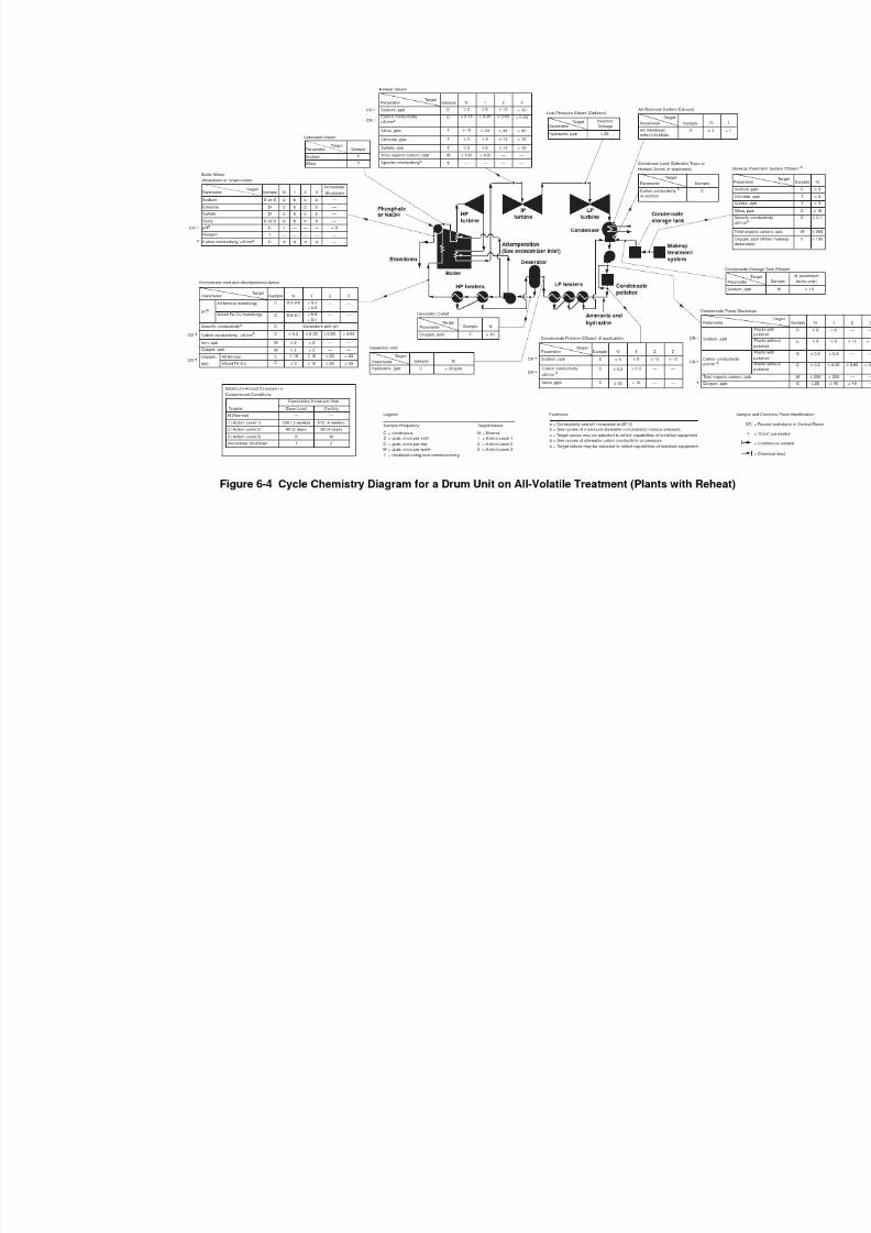
7/18/2019 EPRI Start Up, Lay Up & Shut Down Guidelines for Chemist
http://slidepdf.com/reader/full/epri-start-up-lay-up-shut-down-guidelines-for-chemist 194/256

7/18/2019 EPRI Start Up, Lay Up & Shut Down Guidelines for Chemist
http://slidepdf.com/reader/full/epri-start-up-lay-up-shut-down-guidelines-for-chemist 195/256
All-Volatile Treatment
6-13
Action level 3
Normal
10
8
7
2
6
5
4
3
9
S o d i u m ( p
p m N
a )
1500 19001100 17001300
Pressure (psia)
900 27002300 285025002100
Action level 1
Action level 2
1.0
0.80.7
0.2
0.6
0.5
0.4
0.3
0.9
0.1
11.7 13.19.06.2 17.2 19.614.57.6 10.3 15.8 18.6
Drum Pressure (MPa)
Figure 6-5 All Volatile Treatment: Drum Boiler Water Sodium vs. OperatingPressure (Plants With Reheat)
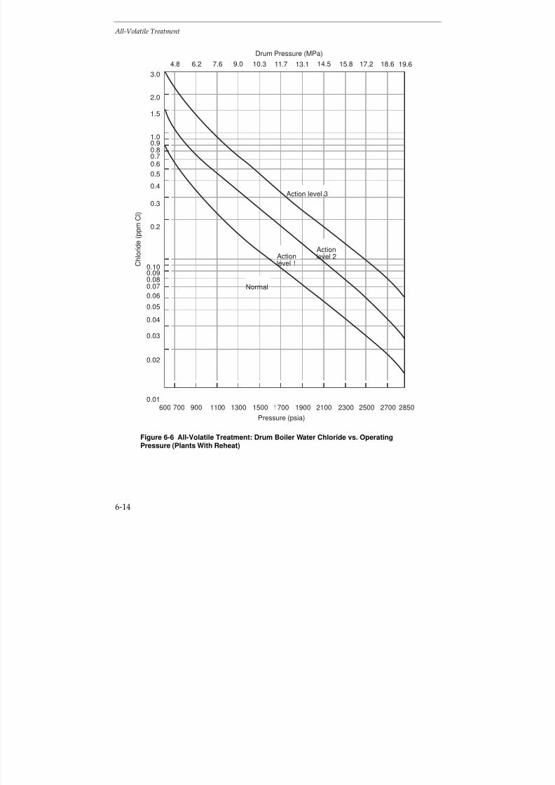
7/18/2019 EPRI Start Up, Lay Up & Shut Down Guidelines for Chemist
http://slidepdf.com/reader/full/epri-start-up-lay-up-shut-down-guidelines-for-chemist 196/256
All-Volatile Treatment
6-14
Pressure (psia)
1300 1700700 15001100600 2500 28502100 270023001900900
C h l o r i d e ( p p m C
l )
Actionlevel 2
Normal
Actionlevel 1
Action level 3
0.10
0.080.07
0.02
0.06
0.05
0.04
0.03
0.09
0.01
1.0
0.80.7
0.2
0.6
0.5
0.4
0.3
0.9
3.0
2.0
1.5
11.7 13.19.06.2 17.2 19.614.57.6 10.3 15.8 18.64.8
Drum Pressure (MPa)
Figure 6-6 All-Volatile Treatment: Drum Boiler Water Chloride vs. OperatingPressure (Plants With Reheat)
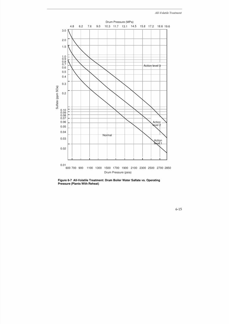
7/18/2019 EPRI Start Up, Lay Up & Shut Down Guidelines for Chemist
http://slidepdf.com/reader/full/epri-start-up-lay-up-shut-down-guidelines-for-chemist 197/256
All-Volatile Treatment
6-15
1.0
0.80.7
0.2
0.6
0.5
0.4
0.3
0.9
Drum Pressure (psia)
3.0
2.0
1.5
1300 1700700 15001100600 2500 28502100 270023001900900
S u l f a t e ( p p m S
O 4
)
Actionlevel 2
Normal
Actionlevel 1
Action level 3
0.10
0.080.07
0.02
0.06
0.05
0.04
0.03
0.09
0.01
11.7 13.19.06.2 17.2 19.614.57.6 10.3 15.8 18.64.8
Drum Pressure (MPa)
Figure 6-7 All-Volatile Treatment: Drum Boiler Water Sulfate vs. OperatingPressure (Plants With Reheat)

7/18/2019 EPRI Start Up, Lay Up & Shut Down Guidelines for Chemist
http://slidepdf.com/reader/full/epri-start-up-lay-up-shut-down-guidelines-for-chemist 198/256
All-Volatile Treatment
6-16
10
87
2
6
5
4
3
9
Drum Pressure (psia)
0.10
0.080.070.06
0.05
0.04
0.03
0.09
20
15
1300 1700700 15001100600 2500 28502100 270023001900900
S i l i c a ( p p m S
i O 2 )
Actionlevel 2
Normal Actionlevel 1
Action level 3
1.0
0.80.7
0.2
0.6
0.5
0.4
0.3
0.9
11.7 13.19.06.2 17.2 19.614.57.6 10.3 15.8 18.64.8
Drum Pressure (MPa)
Figure 6-8 All-Volatile Treatment: Drum Boiler Water Silica vs. Operating Pressure(Plants With Reheat)
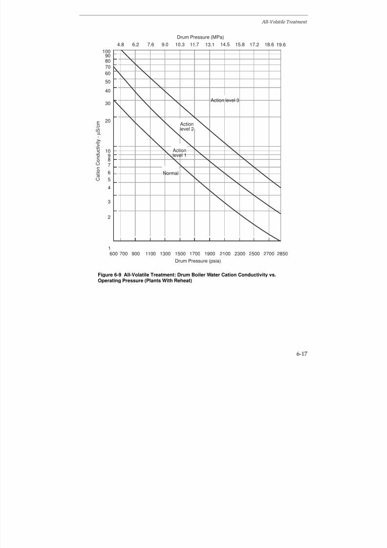
7/18/2019 EPRI Start Up, Lay Up & Shut Down Guidelines for Chemist
http://slidepdf.com/reader/full/epri-start-up-lay-up-shut-down-guidelines-for-chemist 199/256
All-Volatile Treatment
6-17
100
80
70
20
60
50
40
30
90
Drum Pressure (psia)
1300 1700700 15001100600 2500 28502100 270023001900900
C a t i o n C o n d u c t i v i t y - µ S / c m
Normal
Actionlevel 1
Actionlevel 2
Action level 3
10
87
2
6
5
4
3
9
1
11.7 13.19.06.2 17.2 19.614.57.6 10.3 15.8 18.64.8
Drum Pressure (MPa)
Figure 6-9 All-Volatile Treatment: Drum Boiler Water Cation Conductivity vs.Operating Pressure (Plants With Reheat)
7/18/2019 EPRI Start Up, Lay Up & Shut Down Guidelines for Chemist
http://slidepdf.com/reader/full/epri-start-up-lay-up-shut-down-guidelines-for-chemist 200/256
All-Volatile Treatment
6-18
Startup
During off-load conditions, impurities may have been released into the circuit or haveentered from outside, e.g. condenser leaks, CO2 with air ingress. Therefore, duringstartup, it is important to consider the effects of these on the feedwater, boiler waterand steam cation conductivity, silica, sodium, chloride and sulfate concentrationsduring startup. If there is a leak in the reheaters, CO2 and, more importantly, flyash andSO
2, may be drawn in, resulting in acidic condensed steam in the reheaters. There is
some evidence that silica is washed off turbines during shutdown and startup. Oxygenand hydrazine concentrations in the feedwater also require special consideration.Restrictions will need to be applied to these parameters, but some relaxation from thenormal EPRI guideline values may be possible until steady state conditions areachieved.
Section 3 explains how the chemistry curves and action levels can be utilized during
unit startup. Basically, during startups, the initial lower boiler pressure permits boilerwater chemical concentrations to be higher than those at normal unit operatingpressures. Also, the cumulative operating hours per year for which the various actionlevels can be exceeded are twice the values for cycling units, as compared to baseloaded units.
If the boiler has been stored under nitrogen or filled with ammonia and hydrazinesolution, it is necessary to ensure that this is safely vented or disposed.
It is important to prevent high concentrations of oxygen and chloride in the boilerwater, as these can act synergistically and may initiate corrosion
(4). For this reason, the
oxygen concentration of the boiler water should not be allowed to exceed 0.2 ppmduring boiler operation. It is also important to ensure that the pH, cation conductivityand chloride concentration are within the limits given in the EPRI
(1,3) guidelines for
boiler water. It might be possible to eliminate hydrazine in plants with all-ferrousfeedwater heating systems(1) (see Section 7 - Oxygenated Treatment).
Depending on the plant, and the shutdown and layup conditions adopted, several stepswill be required for startup (in addition to filling the boiler following a long shutdownand safely venting the nitrogen, if used). The steps used during startup will be plantspecific and, depending on the practicality, the following stages should be monitored,at least during a trial period:
7/18/2019 EPRI Start Up, Lay Up & Shut Down Guidelines for Chemist
http://slidepdf.com/reader/full/epri-start-up-lay-up-shut-down-guidelines-for-chemist 201/256
All-Volatile Treatment
6-19
Stage during Startup Circuit Monitoring
a) Addition of hydrazine (if used) and
ammonia to the feedwater
pH, cation conductivity and oxygen
b) Additional boiler blowdown pH, cation conductivity, chloride andsuspended corrosion products
c) Care to avoid additional carryover intosteam
Cation conductivity, silica and sodium
At full load, the normal EPRI guideline values given in Figure 6-4 should be achieved.There may be room for relaxation, particularly, as regards silica in steam, duringstartup and the earlier stages of operation and during low load operation, provided theparameters are within the EPRI action levels 1-3, see Figures 6-5 to 6-9. The core
parameters, sodium, cation conductivity and oxygen, given in the EPRI guidelines(1,3)
should be monitored at the condensate pump discharge, condensate polisher outlet (if installed), economizer inlet, boiler water (preferably at downcomer), including pH, andsteam. The normal operating levels, as given in the EPRI guidelines
(1,3), should be
achieved as soon as possible. These are given in Figure 6-4.
A road map showing a scheme for startup of a drum boiler with an all-ferrousfeedwater heating system operating with AVT is given in Figure 6-10. The time taken toachieve the required target values will be plant dependent. This should be determinedfor each unit, used as guidance for subsequent startups and amended in the light of operating experience. The procedure can normally be curtailed for warm and hot starts.
If the high purity feed and boiler water conditions cannot be maintained duringstartup, it may be necessary to resort to another form of chemical conditioning, such asphosphate or caustic treatment. The Selection and Optimization document providesadvice and guidance on the optimum boiler water and feedwater choices for drumunits
(1).

7/18/2019 EPRI Start Up, Lay Up & Shut Down Guidelines for Chemist
http://slidepdf.com/reader/full/epri-start-up-lay-up-shut-down-guidelines-for-chemist 202/256
All-Volatile Treatment
6-20
No
Yes
Step 1
Fill system perAVT guidelines
Fire to boiler
Monitor chemicalparameters
Achieve full pressureand load
Safely vent N2 (if used)Drain storage solutionRefill per AVT guidelines
Reduce O2 to 100 ppband Fe to 100 ppb
Maintain Na, SiO2, pH, Cl,SO4 and cation conductivity
within AVT guidelines bycontrolling pressure and blow-down. Avoid excess carry-over
of impurities into steam
Is system full?
Is system filled withlow O2 scavenger?
(Section 4)
Is system filled withwater per AVT
guidelines?
Proceed withstartup
Maintain temperature rampwithin boiler and turbine
manufacturers requirements
Proceed progressively withpolishers (if fitted), deaerator,economiser in clean-up loop
Step 4
Step 5
Step 5
Step 6
Step 6Step 6
Step 5
Step 3
Step 2
Yes
Yes
No
Step 7
Figure 6-10 AVT - Startup of Drum Boilers with All-Ferrous Feedwater Heaters
7/18/2019 EPRI Start Up, Lay Up & Shut Down Guidelines for Chemist
http://slidepdf.com/reader/full/epri-start-up-lay-up-shut-down-guidelines-for-chemist 203/256
All-Volatile Treatment
6-21
The road map for startup of a drum-type unit operating on AVT with all-ferrousfeedwater heaters, Figure 6-10, can be divided into 7 steps.
The steps are essentially similar to those described in Section 5 for phosphate treatment,except that higher purity water is required for units operating with AVT. Unlike once-through units operating on AVT, described in Section 6.2, control of boiler water puritycan be achieved by blowdown with drum units.
Step 1 - System Stored Dry
If the system has been stored dry (Section 4), it should be filled with water which meetsthe EPRI Guidelines for drum units operating on AVT
(3).
Step 2 - Systems Stored Wet: Low Oxygen Scavenger
If the system has been stored using the low oxygen scavenger procedure (Section 4.8),
the boiler can be fired immediately.Step 3 - System Stored Wet: Excess Ammonia and Hydrazine
If the system has been stored wet with a surplus of ammonia and hydrazine(Section 4.8), it must be drained under nitrogen and refilled with water meeting theEPRI Guidelines for drum units operating on AVT
(3).
Step 4 - System Stored using Nitrogen
If the system has been filled with nitrogen or filled with water, using a nitrogen cap,the nitrogen must be safely vented and the boiler refilled, if necessary, with water
meeting the EPRI Guidelines for drum units operating on AVT(3)
. Startup of the unit canthen proceed.
Step 5 - Cleanup and Firing Boiler
The following limits for the boiler feedwater are required prior to firing the boiler:
Oxygen < 100 ppb
Iron < 100 ppb
During startup, the levels of corrosion products (iron) can be very high initially and
silica may also be a problem. Achieving these limits is greatly facilitated by usingcondensate polishing (if fitted) (See Section 3). When these limits are attained, the boilercan be fired.
Attainment of the prefiring limits will be more difficult in units not equipped withcondensate polisher and/or filtration equipment. Best control will require closecompliance with the guidelines for unit shutdown and layup.
7/18/2019 EPRI Start Up, Lay Up & Shut Down Guidelines for Chemist
http://slidepdf.com/reader/full/epri-start-up-lay-up-shut-down-guidelines-for-chemist 204/256
All-Volatile Treatment
6-22
Step 6 - Monitoring
After firing the boiler, monitoring must be fully implemented, both for chemistryparameters, and to ensure that temperature ramps are maintained according to the boiler and turbine manufacturer’s specifications.
During startup, the concentration vs. pressure curves can be utilized to control sodium,silica, chloride and sulfate (for examples see Figures 6-5 to 6-9). Boiler pressure shouldremain at reduced levels such that these limits are maintained before pressure can beincreased to the next stage. Maximum use of blowdown and condensate polishing (if available) will minimize startup times.
During startup, any chemical excursions must be dealt with quickly and effectively.Increases in feedwater sodium and cation conductivity may indicate contaminationfrom the makeup system, contamination from chemical cleaning operations, condensatepolisher malfunction or condenser leakage. The source must be found and the problem
corrected at once. Excursions affecting (lowering) boiler water pH must be correctedimmediately by feeding trisodium phosphate or 1-2 ppm of sodium hydroxide. Avoidexcess carryover of boiler water impurities into the steam.
Effects of cycle contamination are magnified at startup due to relatively low flow ratesfor condensate, feedwater and steam. Cation conductivity may increase as a result of air ingress due to either aeration of water during the shutdown period or air in-leakageduring startup. The change to boiler water chemistry will be minimal compared tocontamination involving the makeup system, chemical cleaning activities, condensatepolishers or condenser leaks.
Step 7 - Full LoadFull load can be achieved when chemical limits are within the EPRI Guidelines fordrum boilers operating on AVT
(3).
Shutdown
Information is given in Section 4 on shutdown (see Figure 4-8) and below for variousplanned shutdown conditions:
Short shutdown (overnight/weekend) - No change to chemical conditions, leave plantpressurized.
Intermediate shutdown (weekend-week) - Leave plant pressurized or store the boilerunder nitrogen.
Long shutdown (longer than 1 week) - Drain the boiler under nitrogen or blowdownfrom high temperature (e.g. 130°C, 266°F) and maintain the boiler, superheaters andreheaters dry. Continue as described under “Layup”.
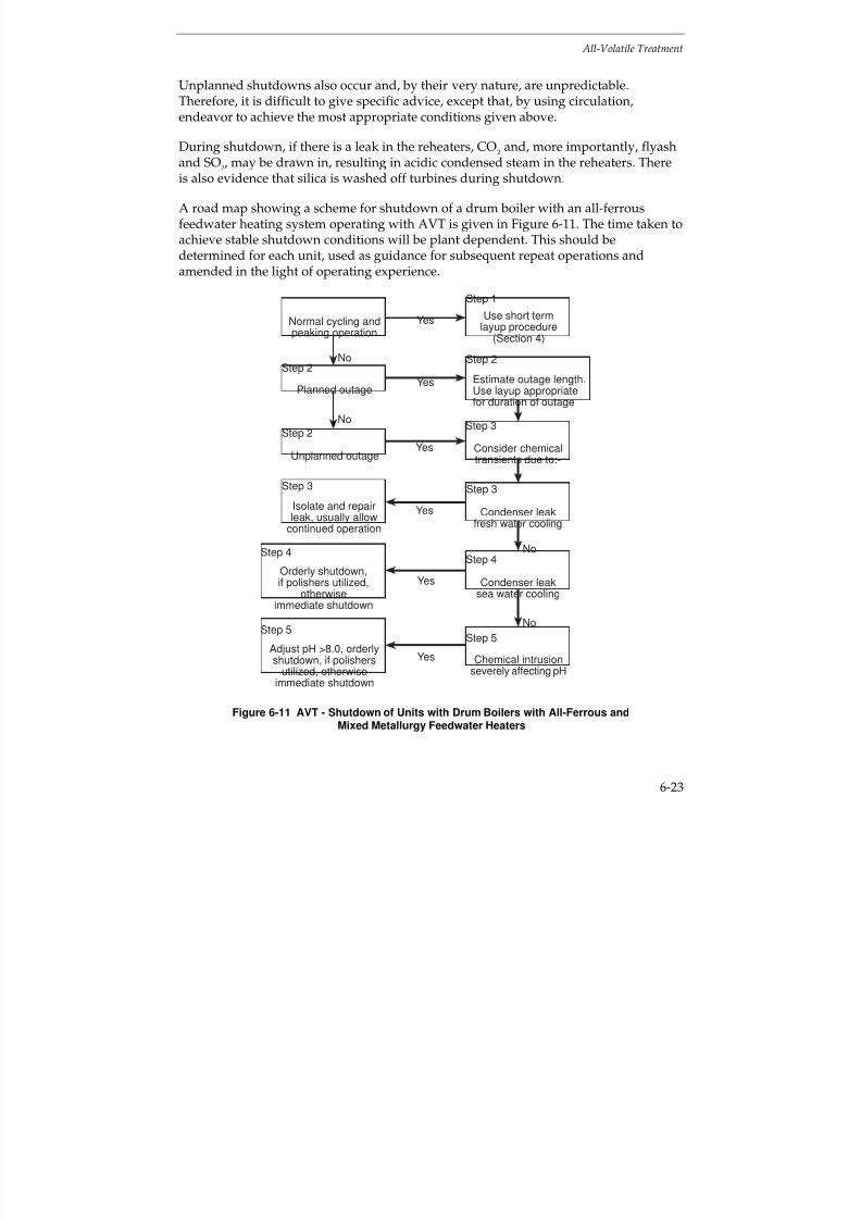
7/18/2019 EPRI Start Up, Lay Up & Shut Down Guidelines for Chemist
http://slidepdf.com/reader/full/epri-start-up-lay-up-shut-down-guidelines-for-chemist 205/256
All-Volatile Treatment
6-23
Unplanned shutdowns also occur and, by their very nature, are unpredictable.Therefore, it is difficult to give specific advice, except that, by using circulation,endeavor to achieve the most appropriate conditions given above.
During shutdown, if there is a leak in the reheaters, CO2 and, more importantly, flyash
and SO2, may be drawn in, resulting in acidic condensed steam in the reheaters. Thereis also evidence that silica is washed off turbines during shutdown.
A road map showing a scheme for shutdown of a drum boiler with an all-ferrousfeedwater heating system operating with AVT is given in Figure 6-11. The time taken toachieve stable shutdown conditions will be plant dependent. This should bedetermined for each unit, used as guidance for subsequent repeat operations andamended in the light of operating experience.
Estimate outage length.Use layup appropriatefor duration of outage
No
Step 1
Use short term
layup procedure(Section 4)
Isolate and repairleak, usually allow
continued operation
Step 2
Step 3
Step 3
Step 2
Yes
Consider chemicaltransients due to:-
Orderly shutdown,if polishers utilized,
otherwiseimmediate shutdown
Normal cycling andpeaking operation
Unplanned outage
Yes
Yes
Yes
Yes
Condenser leakfresh water cooling
Condenser leaksea water cooling
Planned outage
Step 4
Step 2
No
No
Step 3
Step 4
Step 5Step 5
Adjust pH >8.0, orderly
shutdown, if polishersutilized, otherwise
immediate shutdown
Yes Chemical intrusionseverely affecting pH
No
Figure 6-11 AVT - Shutdown of Units with Drum Boilers with All-Ferrous andMixed Metallurgy Feedwater Heaters
7/18/2019 EPRI Start Up, Lay Up & Shut Down Guidelines for Chemist
http://slidepdf.com/reader/full/epri-start-up-lay-up-shut-down-guidelines-for-chemist 206/256
All-Volatile Treatment
6-24
The road map for shutdown of a drum-type unit operating on AVT with all-ferrousfeedwater heaters, Figure 6-11, can be divided into 5 steps.
Again, the steps are essentially similar to those described in Section 5 for phosphatetreatment. Unlike once-through boilers operating on AVT, described in Section 6.2,
control of the boiler water purity can be achieved by blowdown with drum boilers.
Step 1 - Normal Cycling or Peaking: Load Reduction or Shutdown
Normal cycling or peaking load reduction or shutdown presumes a short-term layup asdescribed in Section 4.
An orderly reduction of load can be performed for routine cycling operations. Also, anorderly reduction of load or unit shutdown can be performed when contamination isminimal, as determined by chemical monitoring during such transients.
During orderly load reductions, the condensate cycle and boiler chemical limits should
be adjusted to conform with the AVT guidelines for drum units(3).
Particular care should be exercised to prevent oxygen ingress during this period and blowdown should be maintained at an appropriate level to remove contaminants fromthe system.
Step 2 - Outages
Planned or unplanned outages may be short or longterm, depending on systemdemand or the extent of the work required to return the unit to operation. The length of time required for maintenance must be estimated and, depending on this estimate,
short term or longterm layup should be initiated (Section 4). Chemistry should beadjusted prior to shutdown, as indicated in the various options delineated in Section 4.8(Figure 4-8).
An unplanned outage due to an equipment or system failure can be treated as for aplanned outage.
Step 3 - Chemical Transients: Condenser Leak (Fresh Water)
For condenser leaks with fresh, relatively low dissolved solids cooling water, the leakcan generally be isolated and repaired, while the unit is still operational under reducedload (divided water box) or if the condensate polishing plant (if fitted) maintains thefeedwater quality.
Step 4 - Chemical Transients: Condenser Leaks (Sea Water)
Serious damage can occur to units within a short period of time with intrusion of seawater. Without condensate polishing, the boiler must be shutdown immediately upon

7/18/2019 EPRI Start Up, Lay Up & Shut Down Guidelines for Chemist
http://slidepdf.com/reader/full/epri-start-up-lay-up-shut-down-guidelines-for-chemist 207/256
All-Volatile Treatment
6-25
identifying a significant condenser leak. The addition of trisodium phosphate or 1-2ppm of sodium hydroxide may also be required as the boiler water pH drops.
With condensate polishing (if fitted), the unit can generally be shut down in an orderlyfashion, especially, if the polishers are of the deep bed type. With deep bed polishers, it
is prudent to maintain one or more vessels in the hydrogen form for added protectionagainst condenser leakage.
Powdered resin condensate polishers have less capability for removal of dissolvedimpurities than deep bed polishers. If the leak is small, the use of powdered resinsystems may permit an orderly unit shutdown.
Chemical monitoring is especially important when a sea water leak is suspected. Boilerwater pH is critical, and sodium and cation conductivity will assist in estimating theextent of the leak.
In any event, the unit should be shutdown to repair the condenser leak. Depending on
an evaluation of the cycle chemistry, shut down will be immediate or orderly, asoutlined above.
Substantial intrusion of sea water into the boiler will require that the unit is drainedand refilled with water meeting the EPRI Guidelines for drum boilers operating onAVT
(3).
Step 5 - Chemical Transients: Chemical Intrusion
Some of the many causes of chemical intrusion (in addition to condenser leakage)include:
Makeup water system malfunction
Polisher leakage
— Poor regeneration
— Acid or caustic contamination
Chemical cleaning residue; acid, caustic, other
Maintenance chemicals and preservatives
Silica from flyash or other contaminants from maintenance activities
Minor chemical intrusions can be controlled by employment of idle condensatepolishers, if available.
More serious chemical intrusions may affect (lower) the boiler water pH, necessitatingadjustment of boiler water pH through the addition of trisodium phosphate or 1-2 ppm
7/18/2019 EPRI Start Up, Lay Up & Shut Down Guidelines for Chemist
http://slidepdf.com/reader/full/epri-start-up-lay-up-shut-down-guidelines-for-chemist 208/256
All-Volatile Treatment
6-26
sodium hydroxide. If these treatments are unsuccessful, the unit must be shut down(orderly with polishers, immediate without polishers) if the pH falls below 8 (Figure6-4). The unit then requires careful inspection to determine possible damage, and thenecessity for repair and possible chemical cleaning prior to restart.
Intrusion of chemical contamination requires immediate unit shutdown, draining andflushing the unit. Inspection of critical areas of the system (boiler, superheater, turbine,etc) should be performed to assess the effects of chemical intrusion on the system.Chemical cleaning of the boiler, superheater and turbine may be required, dependingon the results of the inspection. Equipment repairs may be required. In such case, along term layup will be required. (See Section 4.)
During emergency shutdowns, such as for major sea water leaks and extensivechemical contamination, immediate unit shutdown is required. Therefore, little can bedone to adjust cycle chemistry during shutdown, since rapid action is required. Duringsuch occasions, the unit should be drained, flushed and inspected to assess damage, as
outlined previously. Restarting the unit will be contingent upon this inspection, as willlayup provisions.
Cycling and Peaking
As an aid to planning and obtaining optimum conditions, it is important to know asaccurately as possible, the frequency and duration of cycling and peaking, the noticegiven and the variation of load patterns.
Essentially, cycling and peaking plants should operate according to the outline givenabove for startup, load changes and shutdown.
Layup
Layup procedures are presented in Section 4, and a road map suitable for units withdrum boilers operating on AVT is depicted in Figure 4-8.
Store the boiler under nitrogen or, if blowdown from a high temperature, maintain the boiler, superheaters and reheaters dry. Possibly dehumidify the feedwater heaters orallow them to remain wet. Avoid air ingress into the feedwater heaters. Monitoroxygen and pH, and nitrogen and moisture, as appropriate. It is also possible to storethe boiler filled with a solution containing ammonia and hydrazine.
The layup conditions are going to be dependent on the method of layup chosen. Thisshould be determined for each unit and each method of layup used. The informationobtained should be used as guidance for subsequent repeat operations and amended inthe light of operating experience.

7/18/2019 EPRI Start Up, Lay Up & Shut Down Guidelines for Chemist
http://slidepdf.com/reader/full/epri-start-up-lay-up-shut-down-guidelines-for-chemist 209/256
All-Volatile Treatment
6-27
6.4 DRUM UNITS WITH MIXED METALLURGY FEEDWATER HEATING
SYSTEMS
EPRI(5)
has recently produced a report on the State-of-Knowledge of Copper in FossilPlant Cycles as the first stage of the “Program Copper” project. This was in response to
a demand from members, particularly in the US, for improved performance of powerplants containing copper alloys. Traditionally, these have been widely used incondensers, but, in some plants, brass and/or cupro-nickel have also been used for heatexchange surfaces in low and high pressure feedwater heaters. Copper released fromfeedwater heaters deposits in the boiler, increasing the locations where impurities canconcentrate on boiler waterwalls. Thick deposits can lead to overheating and thepresence of copper in deposits complicates chemical cleaning.
Copper in high pressure boilers can be carried over into the steam and deposited inhigh pressure turbines, where even as little as 1 kg can reduce the output capacity of the turbine by 1 MW. This is particularly true for plants operating at more than 2400 psi(16.6 MPa) and is exacerbated further by increasing pressure. The presence of oxygenand the absence of reducing conditions in the feedwater during all periods of operationand shutdown is the main cause of copper transport round the circuit.
It is worth reiterating that startups are generally considered to be the periods of maximum copper transport activity in the cycle. This relates directly to the feedwatersystem not being protected during shutdown periods, i.e. that a reducing environment(ORP < 0mV) is not maintained. Air in-leakage into the LP feedwater heating circuitsincreases the growth of non-protective copper oxides and copper transport. The EPRI“Guiding Principles” for successful operation of units with copper alloys
(5) are:
Keep feedwater copper levels at guideline values (< 2 ppb at the economizer inlet)during normal operation.
Establish conditions which favor cuprous oxide (Cu2O) rather than cupric oxide(CuO) under all operating conditions.
Maintain reducing chemistry (oxidizing-reducing potential, ORP < 0mV) at alltimes, including shutdown and startup.
Control feedwater pH in the range 8.8-9.1.
Implement shutdown procedures and layup programs which effectively minimizecopper transport activity upon return to service.
Consider volatility effects in controlling drum pressure; if possible, maximizeoperating pressure in the range of 2400-2500 psi (16.5-17.2 MPa) and avoid over-pressure operation above this range.

7/18/2019 EPRI Start Up, Lay Up & Shut Down Guidelines for Chemist
http://slidepdf.com/reader/full/epri-start-up-lay-up-shut-down-guidelines-for-chemist 210/256
All-Volatile Treatment
6-28
Current Guidelines
The current guidelines for drum boilers with mixed Fe-Cu metallurgy feedwatersystems are given in Figure 6-4 for reheat plants, including the “core” parameters. Thenormal limits and three action levels for sodium, chloride, sulfate, silica and cation
conductivity in boiler water are given in Figures 6-5 to 6-9 for a range of operatingpressures. Except for pH, oxygen, TOC, iron and copper, the limits for non-reheat plantare generally higher by a factor of two. They are not reproduced here and referenceshould be made to the original documents
(1,3).
Startup
During off-load conditions, impurities may have been released into the circuit or haveentered from outside, e.g. condenser leaks, CO2, with air ingress. Therefore, duringstartup it is important to consider the effects of these on the feedwater, boiler water andsteam cation conductivity, silica, sodium, chloride and, sulfate concentrations. If there
is a leak in the reheaters, CO 2 and, more importantly, flyash and SO2, may be drawn in,resulting in acidic condensed steam in the reheaters. There is some evidence that silicais washed off turbines during shutdown and startup. Oxygen, hydrazine and copperconcentrations in the feedwater and copper concentrations of the steam will alsorequire special consideration, since the presence of oxidizing conditions increase therelease and transport of copper around the circuit.
If the boiler has been stored under nitrogen or filled with ammonia and hydrazinesolution, it is necessary to ensure that this is safely vented or disposed.
It is important to prevent high concentrations of oxygen and chloride in the boilerwater, as these can act synergistically and may initiate corrosion. For this reason, theoxygen concentration of the boiler water should not be allowed to exceed 0.2 ppmduring boiler operation. The presence of oxygen also assists the transport of copper intothe steam, increasing the risk of deposition in the superheater and high pressureturbine. It is also important to ensure that the pH, cation conductivity and chlorideconcentration are within the limits given in the EPRI
(1,3) guidelines for boiler water.
Hydrazine (or volatile reducing agents) should not be eliminated from plants withmixed Fe-Cu feedwater heating systems.
Depending on the plant, and the shutdown and layup conditions adopted, several steps
will be required for startup (in addition to filling the boiler following a long shutdownand safely venting the nitrogen, if used). The steps used during startup will be plantspecific and, depending on the practicality, the following stages should be monitored,at least during a trial period:
Stage during Startup Circuit Monitoring
a) Addition of hydrazine and ammonia to pH, cation conductivity, oxygen and

7/18/2019 EPRI Start Up, Lay Up & Shut Down Guidelines for Chemist
http://slidepdf.com/reader/full/epri-start-up-lay-up-shut-down-guidelines-for-chemist 211/256
All-Volatile Treatment
6-29
the feedwater copper
b) Additional boiler blowdown pH, cation conductivity, chloride andsuspended corrosion products
c) Care to avoid additional carryover into
steam
Cation conductivity, silica, sodium and
copper
At full load, the normal EPRI guidelines values given in Figure 6-4 should be achieved.There may be room for relaxation, particularly, as regards silica in steam, duringstartup and the earlier stages of operation and during low load operation, provided theparameters are within the EPRI action levels 1-3, see Figures 6-5 to 6-9. The coreparameters, sodium, cation conductivity and oxygen given in the EPRI
(1,3) guidelines
should be monitored at the condensate pump discharge, condensate polisher outlet (if installed), economizer inlet, boiler water (preferably at downcomer), including pH, andsteam, including copper. The normal operating levels, as given in the EPRI
(1,3)
guidelines, should be achieved as soon as possible. These are given in Figure 6-4.
A road map showing a scheme for startup of a drum boiler with mixed Fe-Cufeedwater heating system operating with AVT is given in Figure 6-12. The time taken toachieve the required target values will be plant dependent. This should be determinedfor each unit, used as guidance for subsequent startups, and amended in the light of operating experience. The procedure can normally be curtailed for warm and hot starts.
The road map, Figure 6-12, can be divided into 7 steps.
Section 3 explains how the chemistry curves and action levels can be utilized duringunit startup. Basically, during startups, the initial lower boiler pressure permits boilerwater chemical concentrations to be higher than those at normal unit operatingpressures. Also, the cumulative operating hours per year for which the various actionlevels can be exceeded are twice the values for cycling units, as compared to baseloaded units.
If the high purity feed and boiler water conditions can not be maintained duringstartup, it may be necessary to resort to another form of chemical conditioning, such asphosphate or caustic treatment. The Selection and Optimization document providesadvice and guidance on the optimum boiler water and feedwater choices for drumunits
(1).
The steps are essentially similar to those described in Section 5 for phosphate treatment,except that higher purity water is required for units operating with AVT. Unlike once-through units operating on AVT, described in Section 6.2, control of boiler water puritycan be achieved by blowdown with drum units. However, compared with units withall-ferrous feedwater heating systems described in Section 6.3, additionalconsiderations are required for units with mixed Fe-Cu feedwater heaters. To reducethe risk of copper corrosion and transport, the ingress of oxygen must be minimized
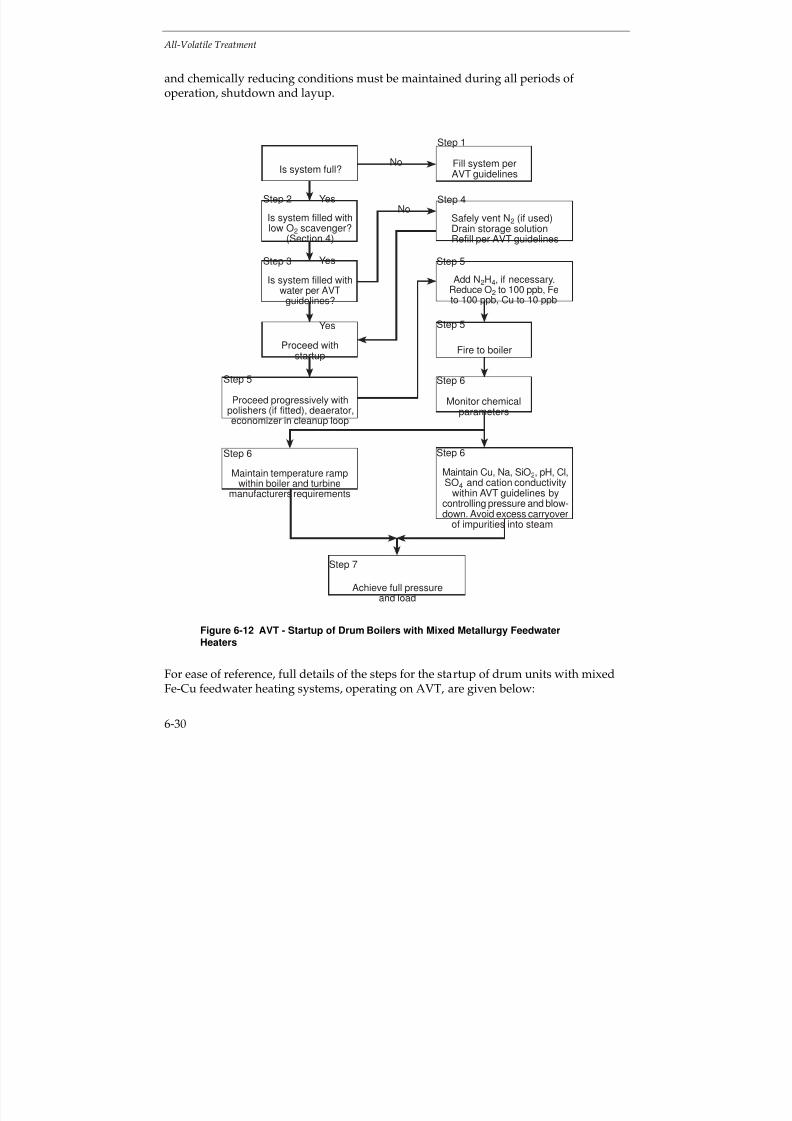
7/18/2019 EPRI Start Up, Lay Up & Shut Down Guidelines for Chemist
http://slidepdf.com/reader/full/epri-start-up-lay-up-shut-down-guidelines-for-chemist 212/256
All-Volatile Treatment
6-30
and chemically reducing conditions must be maintained during all periods of operation, shutdown and layup.
No
Yes
Step 1
Fill system perAVT guidelines
Fire to boiler
Monitor chemicalparameters
Achieve full pressureand load
Safely vent N2 (if used)Drain storage solutionRefill per AVT guidelines
Add N2H4, if necessary.Reduce O2 to 100 ppb, Fe
to 100 ppb, Cu to 10 ppb
Maintain Cu, Na, SiO2, pH, Cl,SO4 and cation conductivity
within AVT guidelines bycontrolling pressure and blow-down. Avoid excess carryover
of impurities into steam
Is system full?
Is system filled withlow O2 scavenger?
(Section 4)
Is system filled withwater per AVT
guidelines?
Proceed withstartup
Maintain temperature rampwithin boiler and turbine
manufacturers requirements
Proceed progressively withpolishers (if fitted), deaerator,economizer in cleanup loop
Step 4
Step 5
Step 5
Step 6
Step 6Step 6
Step 5
Step 3
Step 2
Yes
Yes
No
Step 7
Figure 6-12 AVT - Startup of Drum Boilers with Mixed Metallurgy FeedwaterHeaters
For ease of reference, full details of the steps for the startup of drum units with mixedFe-Cu feedwater heating systems, operating on AVT, are given below:

7/18/2019 EPRI Start Up, Lay Up & Shut Down Guidelines for Chemist
http://slidepdf.com/reader/full/epri-start-up-lay-up-shut-down-guidelines-for-chemist 213/256
All-Volatile Treatment
6-31
Step 1 - System Stored Dry
If the system has been stored dry (Section 4), it should be filled with water which meetsthe EPRI Guidelines for drum units operating on AVT (3).
Step 2 - Systems Stored Wet: Low Oxygen Scavenger
If the system has been stored using the low oxygen scavenger procedure (Section 4.8),the boiler can be fired immediately.
Step 3 - System Stored Wet: Excess Ammonia and Hydrazine
If the system has been stored wet with a surplus of ammonia and hydrazine (Section 4),it must be drained under nitrogen and refilled with water meeting the EPRI Guidelinesfor drum units operating on AVT
(3).
Step 4 - System Stored using Nitrogen
If the system has been filled with nitrogen or filled with water, using nitrogen capping,the nitrogen must be safely vented and the boiler refilled, if necessary, with watermeeting the EPRI Guidelines for drum units operating on AVT
(3). Startup of the unit can
then proceed.
Step 5 - Cleanup and Firing Boiler
The following limits for the boiler feedwater are required prior to firing the boiler:
Oxygen < 100 ppb
Iron < 100 ppbCopper < 10 ppb
During startup, the levels of corrosion products (iron and copper) can be very highinitially and silica may also be a problem. Achieving these limits is greatly facilitated by using condensate polishing (See Section 3). When these limits are attained, the boilercan be fired.
Attainment of the prefiring limits will be more difficult in units not equipped withcondensate polisher and/or filtration equipment. Best control will require closecompliance with the guidelines for unit shutdown and layup.
Step 6 - Monitoring
After firing the boiler, monitoring must be fully implemented, both for chemistryparameters, and to ensure that temperature ramps are maintained according to the boiler and turbine manufacturer’s specifications.
7/18/2019 EPRI Start Up, Lay Up & Shut Down Guidelines for Chemist
http://slidepdf.com/reader/full/epri-start-up-lay-up-shut-down-guidelines-for-chemist 214/256
All-Volatile Treatment
6-32
During startup, the concentration vs. pressure curves can be utilised to control sodium,silica, chloride and sulfate (for examples see Figures 6-5 to 6-9). Boiler pressure shouldremain at reduced levels such that these limits are maintained before pressure can beincreased to the next stage. Maximum use of blowdown and condensate polishing (if available) will minimize startup times.
During startup, any chemical excursions must be dealt with quickly and effectively.Increases in feedwater sodium and cation conductivity may indicate contaminationfrom the makeup system, contamination from chemical cleaning operations, condensatepolisher malfunction or condenser leakage. The source must be found and the problemcorrected at once. Excursions affecting (lowering) boiler water pH must be correctedimmediately by feeding trisodium phosphate or 1-2 ppm of sodium hydroxide.
Effects of cycle contamination are magnified at startup due to relatively low flow ratesfor condensate, feedwater and steam. Cation conductivity may increase as a result of air ingress due to either aeration of water during the shutdown period or air in-leakage
during startup. The change to boiler water chemistry will be minimal compared tocontamination involving the makeup system, chemical cleaning activities, condensatepolishers or condenser leaks.
Avoid excessive carryover of boiler water impurities into the steam. This includescopper, whose transport can be minimized by avoiding ingress of oxygen andmaintaining chemically reducing conditions.
Step 7 - Full Load
Full load can be achieved when chemical limits are within the EPRI Guidelines for
drum boilers operating on AVT
(3)
.
Shutdown
Information is given in Section 4 on shutdown (see Figure 4-8) and below for variousplanned shutdown conditions:
Short shutdown (overnight/weekend) - No change to chemical conditions, leave plantpressurized, avoid air ingress to the feedheaters.
Intermediate shutdown (weekend-week) - Leave plant pressurized or store the boiler
under nitrogen. Avoid air ingress to the feedwater heaters.
Long shutdown (longer than 1 week) - Drain the boiler under nitrogen or blowdownfrom high temperature (e.g. 130°C) and maintain the boiler, superheaters and reheatersdry. Continue as described under “Layup”.
7/18/2019 EPRI Start Up, Lay Up & Shut Down Guidelines for Chemist
http://slidepdf.com/reader/full/epri-start-up-lay-up-shut-down-guidelines-for-chemist 215/256
All-Volatile Treatment
6-33
Unplanned shutdowns also occur and, by their very nature, are unpredictable.Therefore, it is difficult to give specific advice, except that, by using circulation,endeavor to achieve the most appropriate conditions given above.
During shutdown. if there is a leak in the reheaters, CO2 and, more importantly, flyash
and SO2, may be drawn in, resulting in acidic condensed steam in the reheaters. Thereis also evidence that silica is washed off turbines during shutdown.
A road map showing a scheme for shutdown of a drum boiler with a mixed Fe-Cu-feedwater heating system operating with AVT is given in Figure 6-11. The time taken toachieve stable shutdown conditions will be plant dependent. This should bedetermined for each unit, used as guidance for subsequent repeat operations andamended in the light of operating experience.
The road map for shutdown of a unit with a drum boiler operating on AVT with mixedmetallurgy feedwater heaters, Figure 6-11, can be divided into 5 steps.
Again, the steps are essentially similar to those described in Section 5 for phosphatetreatment, except that higher purity water is required for units operating with AVT.Unlike once-through boilers operating on AVT, described in Section 6.2, control of the boiler water purity can be achieved by blowdown with drum boilers. However,compared with units with all-ferrous feedwater heating systems described in Section6.3, additional considerations are required for units with mixed Fe-Cu feedwaterheaters. To reduce the risk of copper corrosion and transport, the ingress of oxygenmust be minimized and chemically reducing conditions must be maintained.
Step 1 - Normal Cycling or Peaking: Load Reduction or Shutdown
Normal cycling or peaking load reduction or shutdown presumes a short term layup asdescribed in Section 4.
An orderly reduction of load can be performed for routine cycling operations. Also, anorderly reduction of load or unit shutdown can be performed when contamination isminimal, as determined by chemical monitoring during such transients.
During orderly load reductions, the condensate cycle and boiler chemical limits should be adjusted to conform with the AVT guidelines for drum units
(3).
Particular care should be exercised to prevent oxygen ingress during this period tominimize pickup of copper. Blowdown should be maintained at an appropriate level toremove contaminants from the system.

7/18/2019 EPRI Start Up, Lay Up & Shut Down Guidelines for Chemist
http://slidepdf.com/reader/full/epri-start-up-lay-up-shut-down-guidelines-for-chemist 216/256
All-Volatile Treatment
6-34
Step 2 - Outages
Planned or unplanned outages may be short or longterm, depending on systemdemand or the extent of the work required to return the unit to operation. The length of time required for maintenance must be estimated and, depending on this estimate,
short term or longterm layup should be initiated (Section 4). Chemistry should beadjusted prior to shutdown, as indicated in the various options deliniated in Section 4.8(Figure 4-8).
An unplanned outage due to an equipment or system failure can be treated as for aplanned outage.
Step 3 - Chemical Transients: Condenser Leak (Fresh Water)
For condenser leaks with fresh, relatively low dissolved solids cooling water, the leakcan generally be isolated and repaired, while the unit is still operational under reduced
load (divided water box) or if the condensate polishing plant (if fitted) maintains thefeedwater quality.
Step 4 - Chemical Transients: Condenser Leaks (Sea Water)
Serious damage can occur to units within a short period of time with intrusion of seawater. Without condensate polishing, the boiler must be shutdown immediately uponidentifying a significant condenser leak. The addition of trisodium phosphate or 1-2ppm of sodium hydroxide may also be required as the boiler water pH drops.
With condensate polishing (if fitted), the unit can generally be shut down in an orderlyfashion, especially, if the polishers are of the deep bed type. With deep bed polishers, itis prudent to maintain one or more vessels in the hydrogen form for added protectionagainst condenser leakage.
Powdered resin condensate polishers have less capability for removal of dissolvedimpurities than deep bed polishers. If the leak is small, the use of powdered resinsystems may permit an orderly unit shutdown.
Chemical monitoring is especially important when a sea water leak is suspected. Boilerwater pH is critical, and sodium and cation conductivity will assist in estimating theextent of the leak.
In any event, the unit should be shut down to repair the condenser leak. Depending onan evaluation of the cycle chemistry, shutdown will be immediate or orderly, asoutlined above.
Substantial intrusion of sea water into the boiler will require that the unit is drainedand refilled with water meeting the EPRI Guidelines for drum boilers operating onAVT
(3).

7/18/2019 EPRI Start Up, Lay Up & Shut Down Guidelines for Chemist
http://slidepdf.com/reader/full/epri-start-up-lay-up-shut-down-guidelines-for-chemist 217/256
All-Volatile Treatment
6-35
Step 5 - Chemical Transients: Chemical Intrusion
Some of the many causes of chemical intrusion (in addition to condenser leakage)include:
Makeup water system malfunction
Polisher leakage
Poor regeneration
Acid or caustic contamination
Chemical cleaning residue; acid, caustic, other
Maintenance chemicals and preservatives
Silica from flyash or other contaminants from maintenance activities
Minor chemical intrusions can be controlled by employment of idle condensatepolishers, if available.
More serious chemical intrusions may affect (lower) the boiler water pH, necessitatingadjustment of boiler water pH through the addition of trisodium phosphate or 1-2 ppmsodium hydroxide. If these treatments are unsuccessful, the unit must be shut down(orderly with polishers, immediate without polishers). The unit then requires carefulinspection to determine possible damage, and the necessity for repair and possiblechemical cleaning prior to restart.
Intrusion of chemical contamination requires immediate unit shutdown, draining andflushing the unit. Inspection of critical areas of the system (boiler, superheater, turbine,etc) should be performed to assess the effects of chemical intrusion on the system.Chemical cleaning of the boiler, superheater and turbine may be required, dependingon the results of the inspection. Equipment repairs may be required. In such case, along term layup will be required. (See Section 4.)
During emergency shutdowns, such as for major sea water leaks and extensivechemical contamination, immediate unit shutdown is required. Therefore, little can bedone to adjust cycle chemistry during shutdown, since rapid action is required. Duringsuch occasions, the unit should be drained, flushed and inspected to assess damage, as
outlined previously. Restarting the unit will be contingent upon this inspection, as willlayup provisions.

7/18/2019 EPRI Start Up, Lay Up & Shut Down Guidelines for Chemist
http://slidepdf.com/reader/full/epri-start-up-lay-up-shut-down-guidelines-for-chemist 218/256
All-Volatile Treatment
6-36
Cycling and Peaking
As an aid to planning and obtaining optimum conditions, it is important to know asaccurately as possible, the frequency and duration of cycling and peaking, the noticegiven and the variation of load patterns.
Essentially, cycling and peaking plant should operate according to the outline givenabove for startup, load changes and shutdown.
Layup
Layup procedures are presented in Section 4, and a road map suitable for drum boilersoperating on AVT is depicted in Figure 4-8.
Store the boiler under nitrogen or, if blowdown from a high temperature, maintain the boiler, superheaters and reheaters dry. Possibly dehumidify the feedwater heaters or
allow them to remain wet. Avoid air ingress to the feedwater heaters, as this leads tothe increased corrosion of copper alloys, particularly in the presence of ammonia.Monitor oxygen and pH, and nitrogen and moisture, as appropriate. It is also possibleto store the boiler filled with a solution containing ammonia and hydrazine. Avoidcontact of solutions with high ammonia concentrations with the copper alloys.
The layup conditions are going to be dependent on the method of layup chosen. Thisshould be determined for each unit and each method of layup used. The informationobtained should be used as guidance for subsequent repeat operations and amended inthe light of operating experience.
6.5 REFERENCES
1. Selection and Optimization of Boiler and Feedwater Treatment for Fossil Plants. ElectricPower Research Institute, Palo Alto, Calif. EPRI TR-105040. March 1997
2. Interim Consensus Guidelines on Fossil Plant Cycle Chemistry. Electric Power ResearchInstitute, Palo Alto, Calif. EPRI CS-4629. June 1986
3. Cycle Chemistry Guidelines for Fossil Plants: All Volatile Treatment. Electric PowerResearch Institute, Palo Alto, Calif. EPRI TR-105041. April 1996
4. G. M. W. Mann and R. Garnsey, “Waterside Corrosion Associated with Two-ShiftBoiler Operation on All-Volatile Treatment Chemistry.” Corrosion 79 Conference.Materials Performance, October 1980, pp 32-38
5. State-of-Knowledge of Copper in Fossil Plant Cycles. Electric Power Research Institute,Palo Alto, Calif. EPRI TR-108460, September 1997
7/18/2019 EPRI Start Up, Lay Up & Shut Down Guidelines for Chemist
http://slidepdf.com/reader/full/epri-start-up-lay-up-shut-down-guidelines-for-chemist 219/256
EPRI L icensed M aterial
7-1
7
OXYGENATED TREATMENT
7.1 INTRODUCTION
For the application of oxygenated treatment (OT) in units with once-through and drum boilers, there are four indispensable prerequisites:
All-ferrous feedwater heater metallurgy (copper alloys may be used only in
condenser tubing).
Cation conductivity < 0.15 µS/cm (at 25°C) in condensate, feedwater, and steam.
Hydrazine and other oxygen scavengers are not used.
Condensate polishing
OT reduces or eliminates most of the typical AVT problems such as(1)
:
1. Flow-accelerated corrosion in the feedwater system and in the economizer inlet
tubes and headers.
2. Deposition of feedwater corrosion products on the boiler feed pump.
3. Corrosion product transport into the boiler resulting in orifice fouling, boilerdeposits and pressure drop problems, thermal fatigue boiler tube failures,overheating boiler tube failures, and frequent chemical cleaning.
4. Turbine fouling.
5. Copper alloy condenser tube failures resulting from ammonia grooving (when
operating with OT at reduced ammonia levels).
Whereas the OT Guideline(1)
covers in detail the transition from AVT to OT and normaloperation on OT, the following sections deal with startup and shutdown procedures,cycling and peaking operation, and layup procedures for once-through and drum boiler units operated on OT.
7/18/2019 EPRI Start Up, Lay Up & Shut Down Guidelines for Chemist
http://slidepdf.com/reader/full/epri-start-up-lay-up-shut-down-guidelines-for-chemist 220/256
EPRI L icensed M aterial
Oxygenated Treatment
7-2
7.2 ALL-FERROUS CYCLES WITH ONCE-THROUGH BOILERS
Current Normal Operating Guidelines
Oxygenated treatment (OT) uses high purity water to minimize corrosion and flow-accelerated corrosion (FAC) in the feedwater train. The normally desired cation
conductivity level in all plant cycle streams is <0.15
S/cm (at 25C); lower values are
preferred and attainable. OT can be applied only in plant cycles with all-ferrousmetallurgy and full-flow condensate polishing downstream of the condenser. With OTfor once-through units, an oxygen level of 30-150 ppb is maintained across the wholeplant cycle. The use of oxygen as a corrosion inhibitor allows satisfactory operationover a large pH range (7-10). Thus, a marked reduction in plant cycle pH comparedwith all-volatile treatment (AVT) is possible. The application of a pH range from 8.0 to8.5 results in a reduction of condensate polisher regeneration frequency and theassociated costs.
During normal operation the vents on the deaerator are closed. It is also veryimportant with OT that the optimum heater vent position is maintained to ensure theheater drains are fully protected from FAC. This usually involves the operatorensuring that an oxidizing environment is present in the drains (ORP > 0mV)
(8).
Figure 7-1 shows the cycle chemistry diagram of a cycle with a once-through boileroperated on OT
(1). Here, the normal target values and the action levels for condensate
pump discharge, combined condensate polisher effluent, economizer inlet, and steampurity as well as for makeup treatment system effluent are provided.
Oxygenated treatment causes very stable conditions regarding the minimum corrosionproduct transport in the plant cycle. A temporary oxygen or ammonia feed loss is notconsidered to be a very serious situation. Efforts should be make to restore the feed of both chemicals as soon as practical. Overfeed of ammonia and oxygen is likewise not aserious event. However, if the condenser tubing is made of admiralty brass, thenammonia overfeed could result in ammonia grooving. Again, efforts should be madeto establish the appropriate dosing as soon as practical. Particularly ammonia overfeeddoes have cost consequences because of additional loading of the condensate polisherswhen operated in the hydrogen-hydroxyl form.
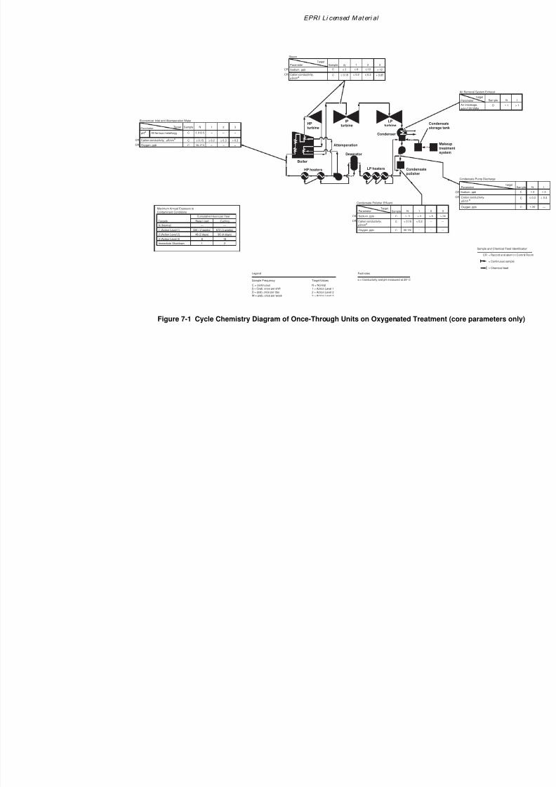
7/18/2019 EPRI Start Up, Lay Up & Shut Down Guidelines for Chemist
http://slidepdf.com/reader/full/epri-start-up-lay-up-shut-down-guidelines-for-chemist 221/256
EPRI Li censed Mat eri al
CR
HP
turbine
LP
turbine
Deaerator
Attemperation
Boiler
LP heaters Condensate
polisher
Makeup
treatment
system
Condensate
storage tank
Condenser
IP
turbine
HP heaters
N (Normal)
Maximum Annual Exposure to
Contaminant Conditions
Targets
Cumulative Hours per Year
Base Load Cycling
1 (Action Level 1)
2 (Action Level 2)
3 (Action Level 3)
—
336 ( 2 weeks)
48 (2 days)
8
1Immediate Shutdown
—
672 (4 weeks)
96 (4 days)
16
2
Con
Pa
Sod
Ox
Ca
µS/
Cation conductivity,
µS/cma
Sodium, ppb
Condensate Polisher Effluent
Parameter
Target
Sample N
C < 0.15
1
< 0.2
2 3C ≤ 3 > 3 > 6 > 24
– –
Economizer Inlet and Attemperation Water
ParameterTarget Sample N
All ferrous metallurgy C 8.0-8.5
1 2
–
3
– pHa
Steam
ParameterTarget
Sample N
Sodium, ppb C ≤ 3
Cation conductivity,
µS/cma
C
1
≤ 6
2
≤ 12
3
> 12CR
≤ 0.15 ≤ 0.2 ≤ 0.3 > 0.65
Cation conductivity, µS/cma
C ≤ 0.15 ≤ 0.2 ≤ 0.3 > 0.3
Oxygen, ppb C 30-150 – –
CR
N = Normal
1 = Action Level 1
2 = Action Level 2
3 = Action Level 3
Target Values
Legend
C = continuous
S = Grab. once per shift
D = grab, once per day
W = grab. once per week
Sample Frequency
Footnotes
a = Conductivity and pH measured at 25° C
Oxygen, ppb C 30-150 – – –
–
–
CR
CR
CR
CR
CR
Air scf
Air R
Par
Figure 7-1 Cycle Chemistry Diagram of Once-Through Units on Oxygenated Treatment (core
7/18/2019 EPRI Start Up, Lay Up & Shut Down Guidelines for Chemist
http://slidepdf.com/reader/full/epri-start-up-lay-up-shut-down-guidelines-for-chemist 222/256
Oxygenated Treatment
7-4
Startup Procedures
Startup is accomplished by essentially the same startup procedure as is used for AVT(Section 6.2). Some minor variations in startup procedures exist, with the variationdepending upon the type of unit shutdown and subsequent layup procedure which
preceded the startup. For a short outage, no layup actions other than discontinuingoxygen feed are recommended. For short duration layups, a relatively quick startup isanticipated.
For longterm layups, increased levels of ammonia are suggested, and some additionalrecirculation and venting are required to reduce ammonia levels and to reduce cationconductivity to acceptable levels during startup. Normal station startup should beperformed as with AVT including ammonia addition but absolutely without hydrazineor other oxygen scavenger addition. Startup should progress through cold and hotcleanup, startup, and ramping activities as customary with AVT. Ammonia addition
begins with the first use of condensate polishers or when the condensate pumps arestarted. Deaerator pegging and venting are performed until oxygen addition is started.
Oxygen addition does not begin until cation conductivity reaches 0.15 µS/cm (at 25°C)and is continuing to downtrend. Deaerator vents should then be positioned ascustomary in steady-state operation. The same is true for heater vents.
Once-through boilers utilize a by-pass system to facilitate cleanup of the pre-boilersystem during startup. This is a system of piping, valves and flash tank (verticalseparator) utilized during starting, stopping and low load operations. Firing a once-through boiler is not permitted unless minimum design limits for feedwater flow aresatisfied. Since once-through boilers have the flow going directly from the economizerthrough the boiler to the turbine, the by-pass system provides protection of the turbineduring startup by isolating the turbine from the boiler by valves.
The by-pass system allows for circulation through the boiler, the feedwater heaters andthe waste cleanup (polishing) system to meet water quality requirements prior to firing.Downstream of the flash tank, the by-pass system directs heater condensate and steamto the deaerator and first point feedwater heater for heat recovery. Steam is suppliedfrom the flash tank for turbine cooling, loading and low load operation up to the once-through transfer load point. At the once-through transfer point, steam flow to the
turbine equals minimum boiler feedwater flow.
One of the most important advantages of OT is that startups can be accomplished muchfaster than when the unit is operated with AVT. There should be no holds or otherramping activities if the OT is operated in the optimum fashion according to the EPRIguidelines(1). For startups following longterm layup, the feedwater iron levels should
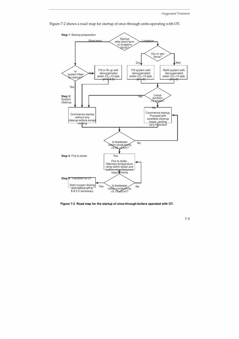
7/18/2019 EPRI Start Up, Lay Up & Shut Down Guidelines for Chemist
http://slidepdf.com/reader/full/epri-start-up-lay-up-shut-down-guidelines-for-chemist 223/256
Oxygenated Treatment
7-5
Figure 7-2 shows a road map for startup of once-through units operating with OT.
Layupduration
<4 weeks?
Yes
No
No
No
Yes
Dry
No
Wet
Short-term Longterm
Yes
Start oxygen dosingand reduce pH to8-8.5 if necessary
Is feedwatercation conductivity
<0.15 µS/cm?
Fill or fill up withdeoxygenated
water (O2<10 ppb,pH 8-8.5)
Fill system withdeoxygenated
water (O2<10 ppb,pH >9)
Refill system withdeoxygenated
water (O2<10 ppb,pH >9)
Issystem filledfor startup?
Startupafter short-term
or longtermlayup?
Step 1: Startup preparation
Step 2:Systemcleanup
Step 3: Fire to boiler
Step 4: Transition to OT
Commence startup.Proceed with
available cleanuploops; ventingvery important
Commence startupwithout any
cleanup actions exceptventing
Is feedwatercation conductivity
<0.65 µS/cm?
Yes
Dry or wetlayup?
Fire to boiler.Maintain temperatureramp within boiler andturbine manufacturers
requirements
Figure 7-2 Road map for the startup of once-through boilers operated with OT.
7/18/2019 EPRI Start Up, Lay Up & Shut Down Guidelines for Chemist
http://slidepdf.com/reader/full/epri-start-up-lay-up-shut-down-guidelines-for-chemist 224/256
Oxygenated Treatment
7-6
As mentioned above, the application of OT in all-ferrous cycles with once-through boiler cycles markedly simplifies and shortens the startup procedure. For this reason,the road map for startup of once-through units operating with OT (Figure 7-2) consistsof only 4 main steps.
Step 1 - Startup Preparation
Startup after short-term or longterm layup?
The first startup actions depend on the layup duration. In case of short-term orintermediate layup, the procedure is simpler and faster compared to the case of a unitwhich was the subject of a longterm layup.
Startup after short-term layup
Is system filled for startup?
Systems filled for startup can start up very fast without any cleanup actions except forheater and deaerator venting. Otherwise the system has to be filled with deoxygenatedwater (O2 < 10 ppb, pH 8-8.5). The cation conductivity of the water used for filling thesystem should meet the EPRI OT Guideline. The startup after short-term layup is anexception because it is, in contrary to startup after longterm layup, performed with afeedwater pH of 8-8.5.
Startup after longterm layup
Dry or wet layup?
If the system has been stored dry it should be filled with deoxygenated water (O2 < 10ppb, pH > 9) which meets the EPRI AVT guideline. If the system has been stored wet,e.g. nitrogen cap combined with an oxygen free (< 10 ppb oxygen) ammonia treated(pH > 9) water, it should be refilled with deoxygenated water (O
2 < 10 ppb, pH > 9)
which meets EPRI AVT Guideline.
Layup duration < 4 weeks?
According to the general OT operation experience, it is possible to commence startup of
units stored for less than 4 weeks without any special cleanup actions except deaeratorand heater venting. In other cases, continue with available cleanup loops and take careof adequate deaerator and heater venting.
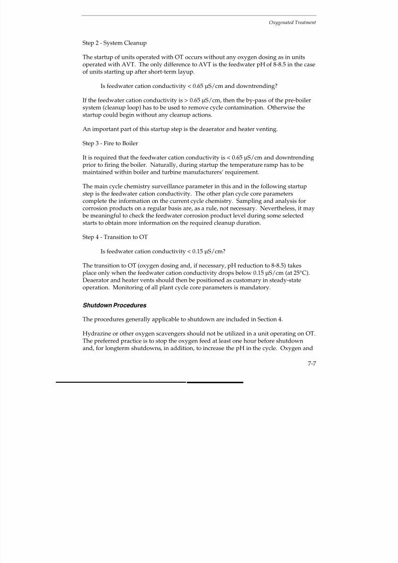
7/18/2019 EPRI Start Up, Lay Up & Shut Down Guidelines for Chemist
http://slidepdf.com/reader/full/epri-start-up-lay-up-shut-down-guidelines-for-chemist 225/256
Oxygenated Treatment
7-7
Step 2 - System Cleanup
The startup of units operated with OT occurs without any oxygen dosing as in unitsoperated with AVT. The only difference to AVT is the feedwater pH of 8-8.5 in the caseof units starting up after short-term layup.
Is feedwater cation conductivity < 0.65 µS/cm and downtrending?
If the feedwater cation conductivity is > 0.65 µS/cm, then the by-pass of the pre-boilersystem (cleanup loop) has to be used to remove cycle contamination. Otherwise thestartup could begin without any cleanup actions.
An important part of this startup step is the deaerator and heater venting.
Step 3 - Fire to Boiler
It is required that the feedwater cation conductivity is < 0.65 µS/cm and downtrendingprior to firing the boiler. Naturally, during startup the temperature ramp has to bemaintained within boiler and turbine manufacturers’ requirement.
The main cycle chemistry surveillance parameter in this and in the following startupstep is the feedwater cation conductivity. The other plan cycle core parameterscomplete the information on the current cycle chemistry. Sampling and analysis forcorrosion products on a regular basis are, as a rule, not necessary. Nevertheless, it may be meaningful to check the feedwater corrosion product level during some selectedstarts to obtain more information on the required cleanup duration.
Step 4 - Transition to OT
Is feedwater cation conductivity < 0.15 µS/cm?
The transition to OT (oxygen dosing and, if necessary, pH reduction to 8-8.5) takesplace only when the feedwater cation conductivity drops below 0.15 µS/cm (at 25°C).Deaerator and heater vents should then be positioned as customary in steady-stateoperation. Monitoring of all plant cycle core parameters is mandatory.
Shutdown Procedures
The procedures generally applicable to shutdown are included in Section 4.
Hydrazine or other oxygen scavengers should not be utilized in a unit operating on OT.The preferred practice is to stop the oxygen feed at least one hour before shutdownand, for longterm shutdowns, in addition, to increase the pH in the cycle. Oxygen and
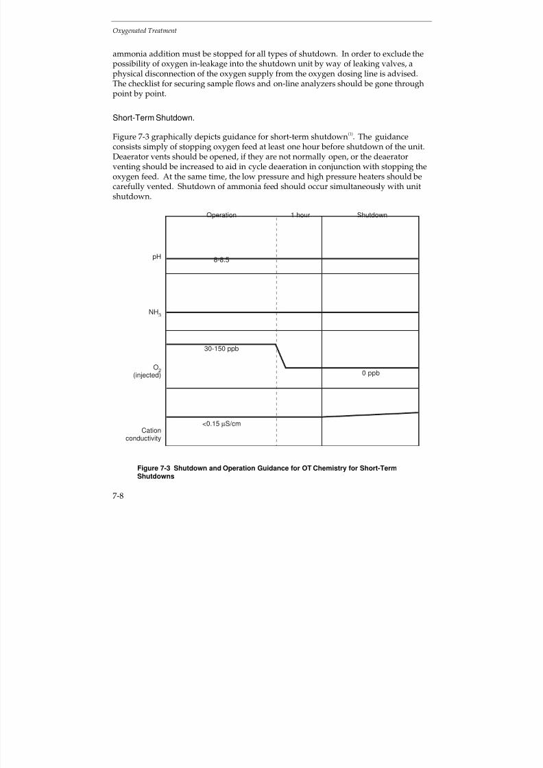
7/18/2019 EPRI Start Up, Lay Up & Shut Down Guidelines for Chemist
http://slidepdf.com/reader/full/epri-start-up-lay-up-shut-down-guidelines-for-chemist 226/256
Oxygenated Treatment
7-8
ammonia addition must be stopped for all types of shutdown. In order to exclude thepossibility of oxygen in-leakage into the shutdown unit by way of leaking valves, aphysical disconnection of the oxygen supply from the oxygen dosing line is advised.The checklist for securing sample flows and on-line analyzers should be gone throughpoint by point.
Short-Term Shutdown.
Figure 7-3 graphically depicts guidance for short-term shutdown(1)
. The guidanceconsists simply of stopping oxygen feed at least one hour before shutdown of the unit.Deaerator vents should be opened, if they are not normally open, or the deaeratorventing should be increased to aid in cycle deaeration in conjunction with stopping theoxygen feed. At the same time, the low pressure and high pressure heaters should becarefully vented. Shutdown of ammonia feed should occur simultaneously with unitshutdown.
pH
NH3
O2
(injected)
Cationconductivity
Operation 1 hour Shutdown
8-8.5
30-150 ppb
0 ppb
<0.15 µS/cm
Figure 7-3 Shutdown and Operation Guidance for OT Chemistry for Short-TermShutdowns
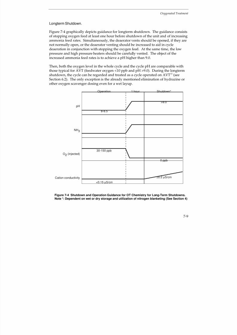
7/18/2019 EPRI Start Up, Lay Up & Shut Down Guidelines for Chemist
http://slidepdf.com/reader/full/epri-start-up-lay-up-shut-down-guidelines-for-chemist 227/256
Oxygenated Treatment
7-9
Longterm Shutdown.
Figure 7-4 graphically depicts guidance for longterm shutdown. The guidance consistsof stopping oxygen feed at least one hour before shutdown of the unit and of increasingammonia feed rates. Simultaneously, the deaerator vents should be opened, if they are
not normally open, or the deaerator venting should be increased to aid in cycledeaeration in conjunction with stopping the oxygen feed. At the same time, the lowpressure and high pressure heaters should be carefully vented. The object of theincreased ammonia feed rates is to achieve a pH higher than 9.0.
Then, both the oxygen level in the whole cycle and the cycle pH are comparable withthose typical for AVT (feedwater oxygen <10 ppb and pH >9.0). During the longtermshutdown, the cycle can be regarded and treated as a cycle operated on AVT
(2) (see
Section 6.2). The only exception is the already mentioned elimination of hydrazine orother oxygen scavenger dosing even for a wet layup.
pH
NH3
O2 (injected)
Cation conductivity
Operation 1 hour Shutdown*
8-8.5
>9.0
0 ppb
≥0.2 µS/cm
<0.15 µS/cm
30-150 ppb
Figure 7-4 Shutdown and Operation Guidance for OT Chemistry for Long-Term Shutdowns.Note *: Dependent on wet or dry storage and utilization of nitrogen blanketing (See Section 4)
7/18/2019 EPRI Start Up, Lay Up & Shut Down Guidelines for Chemist
http://slidepdf.com/reader/full/epri-start-up-lay-up-shut-down-guidelines-for-chemist 228/256
Oxygenated Treatment
7-10
Emergency Shutdown.
In case of an emergency shutdown for reasons of a technical fault (e.g., defects in theelectrical equipment, a boiler tube failure), the unit is shut down with the optimumoperating chemistry. If it is foreseeable that the unit will be brought back into service
very fast (e.g., overnight or over a weekend), additional chemical measures areunnecessary. In case the shutdown will continue for a longer period of time (e.g.,several days or longer), the replacement of oxygen-containing water with an oxygen-free (<10 ppb oxygen) ammonia treated (pH >9) water makes sense. Customary layupprocedures have to be employed for prolonged shutdowns.
Shutdown as a Result of a Serious Chemistry Excursion.
Condenser cooling water in-leakage, makeup water contamination, condensate storagetank contamination or improper condensate polisher regeneration can lead to a
dangerous increase in cation conductivity or sodium or silica content. With OT, acation conductivity excursion is the most serious of chemical transients and must bedealt with very seriously and promptly. In case of an increasing cation conductivity,the following actions are possible:
Cation Conductivity Action Required
S/cm (at 25
C)
<0.15 Normal operating value, continue normal operation.>0.2 and <0.3 Increase system pH to AVT level (9.2-9.6).>0.3 Stop oxygen feed; operate on AVT without the use of
hydrazine or other oxygen scavengers.
>2.0 for 5 minutes or>5.0 for 2 minutes
Stop firing.
After a shutdown forced by a cation conductivity excursion, a unit drain and cleanupusing a non-contaminated water treated in accordance with the AVT requirements isrecommended
(2). With this, the standard cleanup loops including condensate polisher
(if the polisher is not the source of contamination) can be employed.
Cycling and Peaking Operation (3-7)
During cycling and peaking operation, as well as a consequence of a sliding pressureoperation, cation conductivity excursions, oxygen content variations, and pHexcursions may occur. The actions required for cation conductivity excursions arediscussed in the section “Shutdown Procedures”.
Particularly during peaking operation, longer periods with slightly higher cation
conductivity than the steady-state normal operating value (i.e., >0.15
S/cm) are not an
exceptional case. In many cases, even a cation conductivity of <0.3
S/cm (at 25C)
7/18/2019 EPRI Start Up, Lay Up & Shut Down Guidelines for Chemist
http://slidepdf.com/reader/full/epri-start-up-lay-up-shut-down-guidelines-for-chemist 229/256
Oxygenated Treatment
7-11
cannot be reached because of the relatively short duration of the operating period; thenthe unit can be operated only on AVT. There is a risk that such a unit could sooner orlater lose its passivation. In such cases, a longer steady-state operation with a renewedcycle passivation has been proven as the best remedy for reestablishing low corrosionproduct transport throughout the cycle.
In many units the oxygen and ammonia feed are not automatically controlled. As aresult of load fluctuations both the oxygen content and the pH may vary considerably.It is recommended to set the manually adjusted dosing to a lower value within therecommended range for oxygen content (30 ppb) and pH (8.0) during full loadoperation to preclude unnecessary overdosing in low load periods.
Layup Practices
Section 4, “Shutdown and Layup Considerations Common to Most Units” describes the
general information on layup practices for all types of chemistry.
An OT specific variant of wet layup for once-through boilers is the short-term layupwith optimum operating chemistry after an emergency shutdown. If it is foreseeablethat the unit will be brought back into service very fast (e.g., overnight or over aweekend), additional chemical measures are unnecessary. In case the shutdown willcontinue for a longer period of time, additional chemical measures are indispensable.
As an alternative to the usual replacement of oxygen containing system contents withoxygen free (< 10 ppb oxygen) ammonia treated (pH > 9) water, keeping the optimumoperating chemistry even during layup makes sense. With this alternative, a frequentchange or a continuous rinsing of the system contents with an oxygen containing (30-150 ppb oxygen) ammonia treated (pH 8.0-8.5) water has proved to be worthwhile.The sense of such measures is to ensure that the optimum redox conditions are kept inthe system even during the idle period. Naturally, the cation conductivity must notexceed 0.3 µS/cm (at 25°C).
For a longterm layup both dry layup and a nitrogen cap combined with an oxygen free(< 10 ppb oxygen) ammonia treated (pH > 9) water within the system are practicable.Keeping a flow of oxygenated water through the boiler is also possible but in mostcases not economical.
Because OT represents the best available treatment for all-ferrous systems with once-through steam generators, a proper layup of a unit operated with OT is very importantparticularly in the case of prolonged idle periods. The cycle parts at most risk are thesteam and feedwater side of the LP and HP heaters (including drains and vents), thesuperheaters and reheaters, and the LP turbine. These cycle components should always be included in the planned layup measures. See Discussion in Section 4.
7/18/2019 EPRI Start Up, Lay Up & Shut Down Guidelines for Chemist
http://slidepdf.com/reader/full/epri-start-up-lay-up-shut-down-guidelines-for-chemist 230/256
Oxygenated Treatment
7-12
7.3 ALL-FERROUS CYCLES WITH DRUM BOILERS
Current Normal Operating Guidelines
The use of OT for drum units is very similar to that of for once-through units describedin the previous sub-section. Oxygenated treatment (OT) uses high purity water tominimize corrosion and flow-accelerated corrosion (FAC) in the feedwater train. Thenormally desired cation conductivity level in feedwater and steam is < 0.15 µS/cm (at25°C) whereas in the boiler water it is < 1.5 µS/cm (at 25°C); lower values are preferredand attainable. OT can be applied only in plant cycles with all-ferrous feedwatermetallurgy and full-flow condensate polishing downstream of the condenser. With OTfor drum units, an oxygen level of 30-50 ppb is maintained in feedwater and steam.The application of a pH range from 9.0-9.5 enables a slight possible reduction of condensate polisher regeneration frequency. Since a contaminant concentration in boiler water (downcomer) is conceivable even with the best feedwater, the oxygen level
at the drum boiler downcomer is limited to < 10 ppb.
During normal operation the vents on the deaerator are closed. It is also veryimportant with OT that the optimum heater vent position is maintained to ensure theheater drains are fully protected from FAC. This usually involves the operatorensuring that an oxidizing environment is present in the drains (ORP > 0mV)
(8).
Figure 7-5(1)
shows the cycle chemistry diagram of a cycle with a drum boiler operatedon OT. Here, the normal target values and the action levels for condensate pumpdischarge, combined condensate polisher effluent, economizer inlet, boiler water(downcomer), and steam as well as for makeup treatment system effluent are provided.
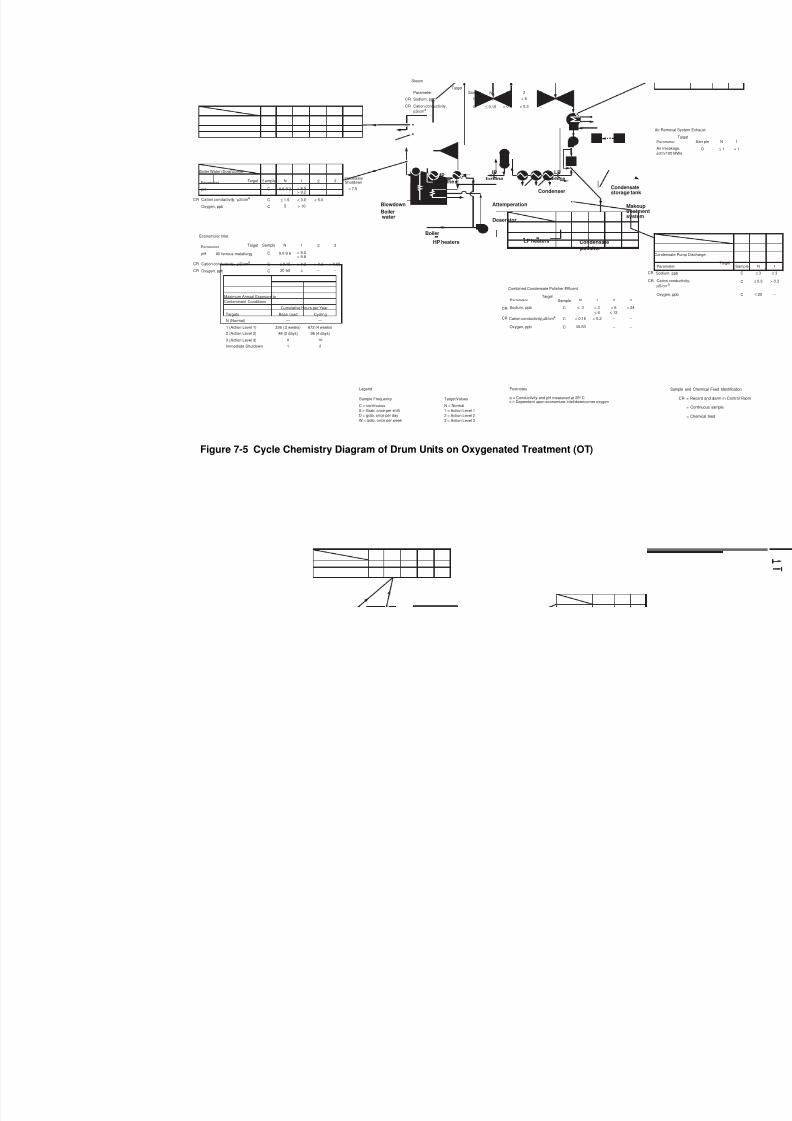
7/18/2019 EPRI Start Up, Lay Up & Shut Down Guidelines for Chemist
http://slidepdf.com/reader/full/epri-start-up-lay-up-shut-down-guidelines-for-chemist 231/256
N (Normal)
Maximum Annual Exposure to
Contaminant Conditions
Targets
Cumulative Hours per Year
Base Load Cycling
1 (Action Level 1)
2 (Action Level 2)
3 (Action Level 3)
—
336 ( 2 weeks)
48 (2 days)
8
1Immediate Shutdown
—
672 (4 weeks)
96 (4 days)
16
2
Con
Pa
Sod
Ox
Ca
µS/
CR
CR
HP
turbine
Boilerwater
HP heaters
Deaerator
Attemperation
IP
turbine
LP
turbine
LP heaters Condensatepolisher
Condenser
Boiler
Blowdown
Condensatestorage tank
Makeuptreatmentsystem
Boiler Water (Downcomer)
ParameterTarget Sample N
C 8.5-9.2
1 2
< 8.5> 9.2
3
– pH
CR Cation conductivity, µS/cma
C ≤ 1.5 < 3.0 < 5.0
Oxygen, ppb C 5 > 10
–
ImmediateShutdown
< 7.5
Economizer Inlet
Parameter Target Sample N
All ferrous metallurgy C 9.0-9.6
1 2
< 9.0> 9.6
3
–
pH
CR Cation conductivity, µS/cma
C ≤ 0.15 > 0.2 > 0.3
Oxygen, ppb C 30-50 c –
CR
CR Cation conductivity, µS/cma
Sodium, ppb
Combined Condensate Polisher Effluent
ParameterTarget
Sample N
C < 0.15
1
> 0.2
2 3
C ≤ 3 > 3
≤ 6
> 6
≤ 12
> 24
– –
– – Oxygen, ppb C 30-50
Steam
ParameterTarget
Sample N
Sodium, ppb C ≤ 3
Cation conductivity,
µS/cma
C
1
> 3
2
> 6
3
> 12CR
≤ 0.15 > 0.2 > 0.3 – CR
> 0.65
Footnotes
a = Conductivity and pH measured at 25° Cc = Dependent upon economizer inlet/downcomer oxygen
CR
Air
scf
Air R
Par
N = Normal
1 = Action Level 1
2 = Action Level 2
3 = Action Level 3
Target Values
Legend
C = continuous
S = Grab. once per shift
D = grab, once per day
W = grab. once per week
Sample Frequency
Figure 7-5 Cycle Chemistry Diagram of Drum Units on Oxygenated Treatment (OT)
7/18/2019 EPRI Start Up, Lay Up & Shut Down Guidelines for Chemist
http://slidepdf.com/reader/full/epri-start-up-lay-up-shut-down-guidelines-for-chemist 232/256
Oxygenated Treatment
7-14
Oxygenated treatment causes very stable conditions regarding the minimum corrosionproduct transport in a plant cycle. A temporary oxygen feed loss is not considered to be a very serious situation. Efforts should be made to restore the feed of oxygen assoon as practical. A temporary ammonia feed loss could result in an undesirable boilerwater pH reduction. Efforts should be made to restore the feed of ammonia as soon aspossible. Overfeed of ammonia is likewise not a serious event. Again, efforts should be made to establish the appropriate dosing as soon as practical. The ammoniaoverfeed does have cost consequences because of additional loading of the condensatepolishers when operated in hydrogen-hydroxyl form. An overfeed of oxygen couldendanger the waterwalls when contamination is present, and for that reason, has to beprecluded by means of appropriate technical measures.
Startup Procedures
Startup is accomplished using essentially the same startup procedure as used for AVT(Section 6.3). Some minor variations in startup procedures exist, with the variationdepending upon the type of unit shutdown and subsequent layup procedure whichpreceded the startup. Since for a short outage, no layup actions other thandiscontinuing oxygen feed are recommended, a relatively quick startup is anticipated.
For longterm layups, in which increased levels of ammonia are used, some additionalrecirculation and venting are required to reduce ammonia levels and to reduce cationconductivity to acceptable levels. Normal station startup should be performed as withAVT including ammonia but absolutely without hydrazine or other oxygen scavengeraddition. Startup should progress through cold and hot cleanup, startup, and ramping
activities as customary with AVT. Ammonia addition begins with the first use of condensate polishers. Deaerator pegging and venting are performed until oxygenaddition is started. The blowdown is used to reduce the boiler water cationconductivity.
Oxygen addition does not begin until feedwater cation conductivity reaches 0.15µS/cm (at 25°C) and is continuing to downtrend and until the boiler water(downcomer) cation conductivity has reached < 1.5 µS/cm (at 25°C). Deaerator ventsshould then be positioned as customary in steady-state operation. The same is true forheater vents.
One of the most important advantages of OT is that startups can be accomplished muchfaster than when the unit is operated with AVT. For startups following short-termlayup, there should be no holds or other ramping activities if the OT is operated in theoptimum fashion according to the EPRI guidelines
(1). For startups following longterm
layup, the feedwater iron levels still should not be a critical parameter. Here the mainmonitoring parameters are economizer inlet cation conductivity, oxygen, and pH (by

7/18/2019 EPRI Start Up, Lay Up & Shut Down Guidelines for Chemist
http://slidepdf.com/reader/full/epri-start-up-lay-up-shut-down-guidelines-for-chemist 233/256
Oxygenated Treatment
7-15
means of specific conductivity) as well as boiler water cation conductivity, oxygen, andpH.
Section 3 explains how the chemistry curves and action levels can be utilized duringunit startup. Basically, during startups, the initial lower boiler pressure permits boiler
water chemical concentrations to be higher than those at normal unit operatingpressures. Also, the cumulative operating hours per year for which the various actionlevels can be exceeded are twice the values for cycling units, as compared to baseloaded units.
Figure 7-6 shows a road map for startup of drum-type units operating with OT.
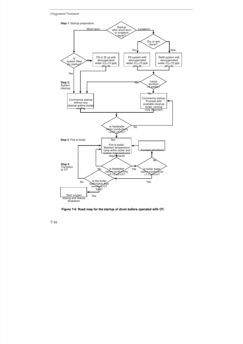
7/18/2019 EPRI Start Up, Lay Up & Shut Down Guidelines for Chemist
http://slidepdf.com/reader/full/epri-start-up-lay-up-shut-down-guidelines-for-chemist 234/256
Oxygenated Treatment
7-16
Layupduration
<4 weeks?
Yes
No
Yes
No
Yes
Dry
No
Wet
Short-term Longterm
Yes
Is feedwatercation conductivity
<0.15 µS/cm?
Fill or fill up withdeoxygenated
water (O2<10 ppb,pH >9)
Fill system withdeoxygenated
water (O2<10 ppb,pH >9)
Refill system withdeoxygenated
water (O2<10 ppb,pH >9)
Issystem filledfor startup?
Startupafter short-term
or longtermlayup?
Step 1: Startup preparation
Step 2:Systemcleanup
Step 3: Fire to boiler
Step 4:Transitionto OT
Commence startup.Proceed with
available cleanuploops; ventingvery important
Commence startupwithout any
cleanup actions exceptventing
Is feedwatercation conductivity
<0.65 µS/cm?
No
Dry or wetlayup?
Increase blowdown
Is boiler watercation conductivity
<1.5 µS/cm?
Is the boilerload higher than
minimum OTload?
Yes
YesNo
Start oxygendosing and reduce
blowdown
Fire to boiler.Maintain temperatureramp within boiler andturbine manufacturers
requirements
No
Figure 7-6 Road map for the startup of drum boilers operated with OT.
7/18/2019 EPRI Start Up, Lay Up & Shut Down Guidelines for Chemist
http://slidepdf.com/reader/full/epri-start-up-lay-up-shut-down-guidelines-for-chemist 235/256
Oxygenated Treatment
7-17
The application of OT in all-ferrous cycles with drum-type boilers markedly simplifiesand shortens the startup procedure over that for AVT. For this reason, the road mapfor startup of drum-type units operating with OT (Figure 7-6) consists of only 4 mainsteps.
Step 1 - Startup Preparation
Startup after short-term or longterm layup?
The first startup actions depend on the layup duration. In case of short-term orintermediate layup, the procedures are simpler and faster than in the case of a unitwhich was the subject of a longterm layup.
Startup after short-term layup
Is system filled for startup?
Systems filled for startup can start up very fast, without any cleanup actions except forheater and deaerator venting. Otherwise the system has to be filled with deoxygenatedwater (O2 < 10 ppb, pH > 9). The cation conductivity of the water used for systemfilling should meet the EPRI AVT Guideline
(2).
Startup after longterm layup
Dry or wet layup?
If the system has been stored dry, it should be filled with deoxygenated water (O2 < 10ppb, pH > 9) which meets the EPRI AVT guideline. If the system has been stored wet,e.g. nitrogen cap combined with an oxygen free (< 10 ppb oxygen) ammonia treated(pH > 9) water, it should be refilled with deoxygenated water (O 2 < 10 ppb, pH > 9)which meets EPRI AVT Guideline.
Layup duration < 4 weeks?
According to the general OT operation experience, it is possible to commence startup of units stored for less than 4 weeks without any special clean-up actions except deaeratorand heater venting. In other cases, continue with available cleanup loops and take care
of adequate deaerator and heater venting.
Step 2 - System Cleanup
The startup of units operated with OT occurs without any oxygen dosing, as with AVT.
Is feedwater cation conductivity < 0.65 µS/cm?
7/18/2019 EPRI Start Up, Lay Up & Shut Down Guidelines for Chemist
http://slidepdf.com/reader/full/epri-start-up-lay-up-shut-down-guidelines-for-chemist 236/256
Oxygenated Treatment
7-18
If feedwater cation conductivity is > 0.65 µS/cm, the by-pass of the pre-boiler system(cleanup loops) can be used to remove cycle contamination (if a by-pass is available).Otherwise the startup could begin without any cleanup actions. An important part of this startup step is the deaerator and heater venting.
Step 3 - Fire to Boiler
It is required that the feedwater cation conductivity reaches < 0.65 µS/cm and tends todowntrend prior to firing the boiler. Naturally, during startup the temperature ramphas to be maintained within boiler and turbine manufacturers’ requirement.
The main cycle chemistry surveillance parameter in this and in the following startupstep is the feedwater cation conductivity and pH as well as boiler water cationconductivity and pH. The other plant cycle core parameters complete the informationon the current cycle chemistry. Sampling and analysis for corrosion products on aregular basis are, as a rule, not necessary. Nevertheless, it may be meaningful to checkthe feedwater corrosion product level during some selected starts to get moreinformation on the required cleanup duration.
Step 4 - Transition to OT
Is feedwater cation conductivity < 0.15 µS/cm?
A feedwater cation conductivity below 0.15 µS/cm (at 25°C) is the first precondition forthe transition to OT. Deaerator and heater vents should then be positioned ascustomary in steady-state operation.
Is boiler water conductivity < 1.5 µS/cm?
Reaching this value is the second precondition for the transition to OT. In case of need,the blowdown is used to reduce the boiler water cation conductivity.
Is the boiler load higher than minimum OT load?
The transition to OT is possible only if the boiler load reaches the unit-specificminimum OT load. See EPRI Guidelines
(1) for information on establishing the oxygen
recirculation ratio and the minimum load acceptable for oxygen addition. This is the
last precondition before the transition to OT. Otherwise, the unit has to continueoperation with AVT.
Start oxygen dosing.
Only when the three above mentioned preconditions are fulfilled (feedwater cationconductivity < 0.15 µS/cm, boiler water cation conductivity < 1.5 µS/cm, and boiler
7/18/2019 EPRI Start Up, Lay Up & Shut Down Guidelines for Chemist
http://slidepdf.com/reader/full/epri-start-up-lay-up-shut-down-guidelines-for-chemist 237/256
Oxygenated Treatment
7-19
load higher than minimum OT load), is oxygen dosing permitted. If possible, the blowdown can be reduced. Deaerator and heater vents should then be positioned ascustomary in steady-state operation.
Monitoring of all plant cycle core parameters is important and indispensable during
Step 4.
Shutdown Procedures
The procedures generally applicable to shutdown are included in Section 4.
Hydrazine and other oxygen scavengers should not be utilized in a unit operating onOT. The preferred practice is to stop the oxygen feed at least one hour beforeshutdown and, for longterm shutdowns, in addition, to increase the pH in the cycle.The maximum tolerable pH value depends on the condenser metallurgy. If the
condenser tubing is made of admiralty brass, then a higher pH could result in ammoniagrooving. Oxygen and ammonia addition must be stopped for all types of shutdown.In order to exclude the possibility of oxygen in-leakage into the shutdown unit by wayof leaking valves, a physical disconnection of the oxygen supply from the oxygendosing line is advised. The checklist for securing sample flows and on-line analyzersshould be gone through point by point.
Short-Term Shutdown.
Figure 7-7 graphically depicts guidance for short-term shutdown(1)
. The guidance
consists simply of stopping oxygen feed at least one hour before shutdown of the unit.Deaerator vents should be opened, if they are not normally open, or the deaeratorventing should be increased to aid in cycle deaeration in conjunction with stoppingoxygen feed. At the same time, the low pressure and high pressure heaters should becarefully vented. Shutdown of ammonia feed should occur simultaneously with unitshutdown.
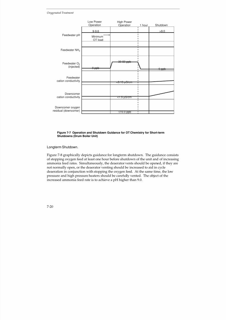
7/18/2019 EPRI Start Up, Lay Up & Shut Down Guidelines for Chemist
http://slidepdf.com/reader/full/epri-start-up-lay-up-shut-down-guidelines-for-chemist 238/256
Oxygenated Treatment
7-20
Feedwater pH
Feedwater NH3
Low PowerOperation
High PowerOperation Shutdown
9-9.6
0 ppb
>9.0
0 ppb
1 hour
Feedwater O2
(injected)
Feedwatercation conductivity
Downcomercation conductivity
Downcomer oxygenresidual (downcomer)
30-50 ppb
<0.15 µS/cm
<1.5 µS/cm
≤10.0 ppb
MinimumOT load
Figure 7-7 Operation and Shutdown Guidance for OT Chemistry for Short-termShutdowns (Drum Boiler Unit)
Longterm Shutdown.
Figure 7-8 graphically depicts guidance for longterm shutdown. The guidance consistsof stopping oxygen feed at least one hour before shutdown of the unit and of increasingammonia feed rates. Simultaneously, the deaerator vents should be opened, if they arenot normally open, or the deaerator venting should be increased to aid in cycle
deaeration in conjunction with stopping the oxygen feed. At the same time, the lowpressure and high pressure heaters should be carefully vented. The object of theincreased ammonia feed rate is to achieve a pH higher than 9.0.
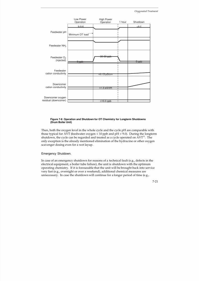
7/18/2019 EPRI Start Up, Lay Up & Shut Down Guidelines for Chemist
http://slidepdf.com/reader/full/epri-start-up-lay-up-shut-down-guidelines-for-chemist 239/256
Oxygenated Treatment
7-21
Feedwater pH
Feedwater NH3
Low PowerOperation
High PowerOperation Shutdown
9-9.6
0 ppb
>9.0
0 ppb
1 hour
Feedwater O2
(injected)
Feedwatercation conductivity
Downcomercation conductivity
Downcomer oxygenresidual (downcomer)
30-50 ppb
<0.15 µS/cm
<1.5 µS/cm
≤10.0 ppb
Minimum OT load
Figure 7-8 Operation and Shutdown for OT Chemistry for Longterm Shutdowns(Drum Boiler Unit)
Then, both the oxygen level in the whole cycle and the cycle pH are comparable withthose typical for AVT (feedwater oxygen < 10 ppb and pH > 9.0). During the longtermshutdown, the cycle can be regarded and treated as a cycle operated on AVT
(2). The
only exception is the already mentioned elimination of the hydrazine or other oxygenscavenger dosing even for a wet layup.
Emergency Shutdown.
In case of an emergency shutdown for reasons of a technical fault (e.g., defects in theelectrical equipment, a boiler tube failure), the unit is shutdown with the optimumoperating chemistry. If it is foreseeable that the unit will be brought back into servicevery fast (e.g., overnight or over a weekend), additional chemical measures areunnecessary. In case the shutdown will continue for a longer period of time (e.g.,
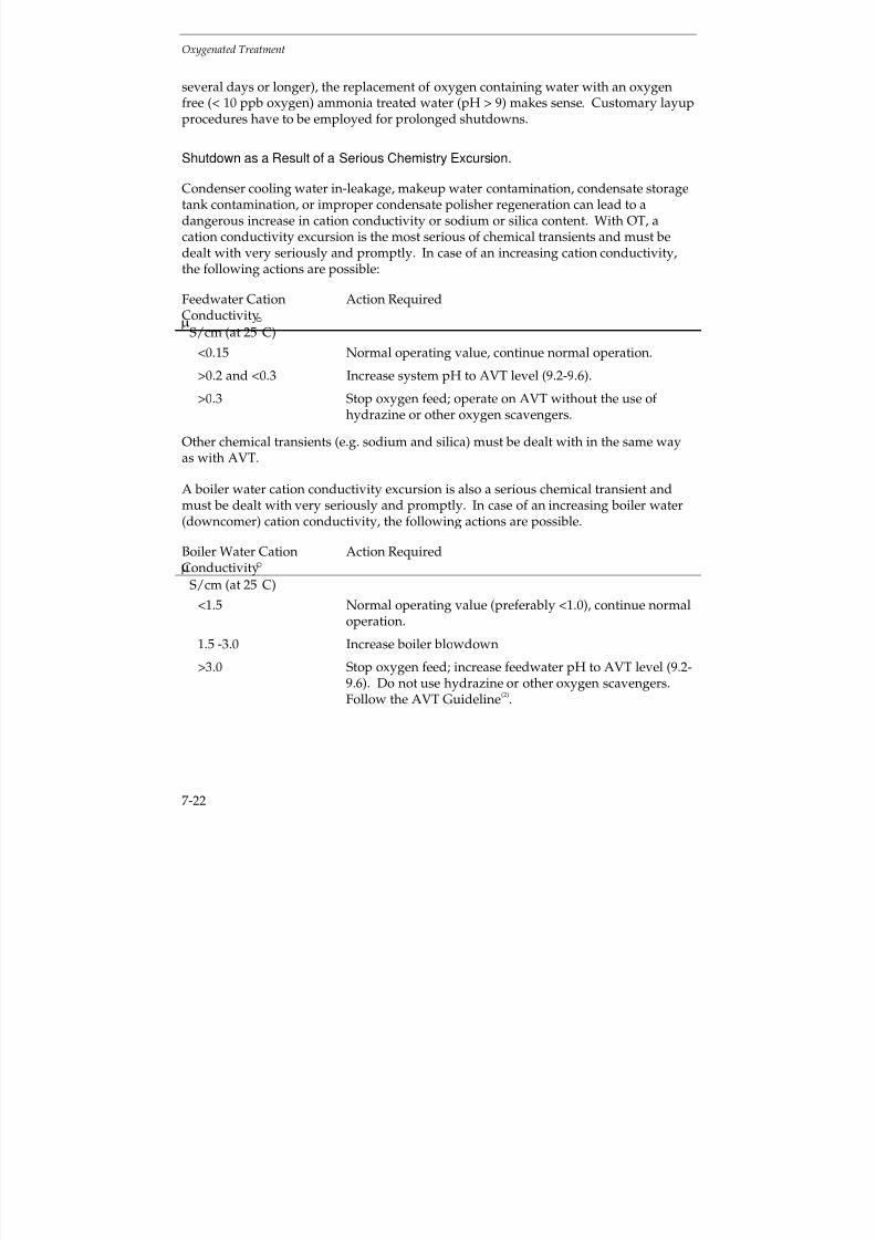
7/18/2019 EPRI Start Up, Lay Up & Shut Down Guidelines for Chemist
http://slidepdf.com/reader/full/epri-start-up-lay-up-shut-down-guidelines-for-chemist 240/256
Oxygenated Treatment
7-22
several days or longer), the replacement of oxygen containing water with an oxygenfree (< 10 ppb oxygen) ammonia treated water (pH > 9) makes sense. Customary layupprocedures have to be employed for prolonged shutdowns.
Shutdown as a Result of a Serious Chemistry Excursion.
Condenser cooling water in-leakage, makeup water contamination, condensate storagetank contamination, or improper condensate polisher regeneration can lead to adangerous increase in cation conductivity or sodium or silica content. With OT, acation conductivity excursion is the most serious of chemical transients and must bedealt with very seriously and promptly. In case of an increasing cation conductivity,the following actions are possible:
Feedwater CationConductivity
Action Required
S/cm (at 25
C)<0.15 Normal operating value, continue normal operation.
>0.2 and <0.3 Increase system pH to AVT level (9.2-9.6).
>0.3 Stop oxygen feed; operate on AVT without the use of hydrazine or other oxygen scavengers.
Other chemical transients (e.g. sodium and silica) must be dealt with in the same wayas with AVT.
A boiler water cation conductivity excursion is also a serious chemical transient and
must be dealt with very seriously and promptly. In case of an increasing boiler water(downcomer) cation conductivity, the following actions are possible.
Boiler Water CationConductivity
Action Required
S/cm (at 25
C)
<1.5 Normal operating value (preferably <1.0), continue normaloperation.
1.5 -3.0 Increase boiler blowdown
>3.0 Stop oxygen feed; increase feedwater pH to AVT level (9.2-9.6). Do not use hydrazine or other oxygen scavengers.Follow the AVT Guideline
(2).
7/18/2019 EPRI Start Up, Lay Up & Shut Down Guidelines for Chemist
http://slidepdf.com/reader/full/epri-start-up-lay-up-shut-down-guidelines-for-chemist 241/256
Oxygenated Treatment
7-23
Cycling and Peaking Operation
During cycling and peaking operation, as well as a consequence of a sliding pressureoperation, cation conductivity excursions, oxygen content variations, and pHexcursions may occur. The actions required for cation conductivity excursions are
discussed under “Shutdown Procedures”.
Particularly during peaking operation longer periods with slightly higher feedwatercation conductivity than the steady-state normal operating value (i.e., < 0.15 µS/cm at25°C) are not an exceptional case. In many cases, even a feedwater cation conductivityof < 0.3 µS/cm (at 25°C) cannot be reached because of the relatively short duration of the operating period; then the unit can be operated only on AVT. There is a risk thatsuch a unit could sooner or later lose its passivation. In such cases, a longer steady-state operation with a renewed cycle passivation has been proven as the best remedyfor reestablishing low corrosion product transport throughout the cycle.
During the conversion to OT, the oxygen recirculation ratio and a minimum loadacceptable for oxygen addition should have been selected
(1). If the boiler is operated at
a lower load than the selected minimum OT load, the oxygen feed should be shut off.
Layup Practices
Section 4, “Shutdown and Layup Considerations Common to Most Units” describes thegeneral information on layup practices for all types of chemistry.
An OT specific variant of wet layup for drum boilers is the short-term layup with
optimum operating chemistry after an emergency shutdown. If it is foreseeable that theunit will be brought back into service very fast (e.g., overnight or over a weekend),additional chemical measures are unnecessary. In case the shutdown will continue fora longer period of time, additional measures are indispensable.
For a longterm layup both dry layup and a nitrogen cap combined with an oxygen free(< 10 ppb oxygen) ammonia treated (pH >9) water within the system are practicable.
OT represents one of the best available treatments for all-ferrous systems with drum boilers. Nevertheless, a proper layup of such a unit operated with OT is very
important particularly in case of prolonged idle periods. The cycle parts at most riskare the steam and feedwater side of the LP and HP heaters (including drains andvents), the waterwalls and the drum, the superheaters and reheaters, and the LPturbine. All mentioned cycle components should always be included in the plannedlayup measures. See discussion in Section 4.
7/18/2019 EPRI Start Up, Lay Up & Shut Down Guidelines for Chemist
http://slidepdf.com/reader/full/epri-start-up-lay-up-shut-down-guidelines-for-chemist 242/256
Oxygenated Treatment
7-24
7.4 REFERENCES
1. Cycle Chemistry Guidelines for Fossil Plants: Oxygenated Treatment. EPRI TR-102285,Dec. 1994.
2. Cycle Chemistry Guidelines for Fossil Plants: All-Volatile Treatment. EPRI TR-105041,April 1996.
3. A. H. Rudd, J. M. Tanzosh, Developments Applicable to Improved Coal-Fired PowerPlants, Nov 19-21, 1986. Electric Power Research Institute, Palo Alto, Calif. USA.
4. Babcock & Wilcox 7A-1K32, Nov. 1995. Operating Instructions for Universal PressureBoilers. Babcock & Wilcox-A McDermott Co., 20 South Van Buren, Barberton, Ohio
USA.
5. Babcock & Wilcox 7A-1, 1-K32 (FPG) Aug 9, 1982. Initial Waterside Clean-upUniversal Pressure Boilers (Boilers with Integral Primary Superheaters) , Babcock &Wilcox-A McDermott Co., 20 South Van Buren, Barberton, Ohio, USA.
6. A. H. Rudd, Variable Pressure Boiler Operation, Canadian Electrical Association, Sept.18-20, 1972, Calgary, Alberta, Canada BR-978 PGTP 72-53. Babcock & Wilcox-AMcDermott Co., 20 South Van Buren Avenue, Barberton, Ohio, USA.
7. Combustion Fossil Power, Published by Combustion Engineering, Windsor Locks,
Connecticut, 1991, 4th Edition Chapter 7, Central Station Steam Generators.
8. R. B. Dooley and J. Matthews. “The Current State of Cycle Chemistry for FossilPlants.” Fifth International Conference on Fossil Plant Cycle Chemistry. ProceedingsEd. By R. B. Dooley and J. Matthews. EPRI TR-108459, November 1997.
7/18/2019 EPRI Start Up, Lay Up & Shut Down Guidelines for Chemist
http://slidepdf.com/reader/full/epri-start-up-lay-up-shut-down-guidelines-for-chemist 243/256
EPRI L icensed M aterial
8-1
8
CAUSTIC TREATMENT FOR DRUM BOILERS
8.1 INTRODUCTION
With the “traditional” form of all-volatile treatment, ammonia and hydrazine areadded to the feedwater to provide chemical conditions that protect the feedwaterheaters, boiler, superheater, reheater and turbine against corrosion, without furtherchemical additions.
All-volatile treatment can also be used for drum-type boilers(1)
, provided high purityfeedwater is available and the build-up of impurities in the boiler water is strictlycontrolled. The absence of a solid alkalizing chemical in the boiler water gives lessprotection against corrosion, but also reduces the risk of carrying over boiler water saltsand solid alkalizing chemicals into the steam. If the high purity feed and boiler waterconditions can not be maintained during startup, operation and shutdown, it may benecessary to adopt another form of chemical conditioning, such as phosphate (seesection 5) or caustic treatment, as discussed below.
Preliminary guidance on the use of caustic treatment of boiler water was published in
an EPRI(2) report on Sodium Hydroxide for Conditioning the Boiler Water of Drum-Type Boilers in 1995. Cycle diagrams were provided for drum-type boilers with allferrous and mixed Fe-Cu metallurgy feedwater heating systems. Only high pressuredrum boilers with reheat were considered and EPRI interim guidance with the normallimits and three action levels and “core” parameters were proposed for 2500 psi (17MPa) coal fired drum-type boilers. Guidance was included on the application,experience, benefits, limitations and implementation of caustic treatment.
Further considerations of caustic treatment were included in the EPRI report onSelection and Optimization of Boiler Water and Feedwater Treatment of Fossil Plants
(3).
As an aid to planning and obtaining the optimum operating conditions for cycling,startup, shutdown and layup, it is important to know as accurately as possible, whatnotice will be given of shutdown, the period of outage and for startup.
In general, the features for the feedwater and steam for all-volatile treatment (AVT) fordrum boilers, also apply to caustic treatment (CT). However, these need to besupplemented by additional considerations for the boiler water. Some units with drum
7/18/2019 EPRI Start Up, Lay Up & Shut Down Guidelines for Chemist
http://slidepdf.com/reader/full/epri-start-up-lay-up-shut-down-guidelines-for-chemist 244/256
EPRI L icensed M aterial
Caustic Treatment for Drum Boilers
8-2
boilers may be equipped with a condensate polisher, but many units are not and,therefore, will be more susceptible to the effects of condenser leaks.
Caustic treatment can be used for drum boilers with all-ferrous and mixed metallurgyfeedwater heating systems. As with phosphate treatment, adding sodium hydroxide as
a solid alkalizing agent to the boiler water, increases the tolerance of the boiler toingress of corrosive contaminants, such as chloride. However, if present in too high aconcentration, it can lead to caustic gouging and increased boiler corrosion. In addition,special care has to be taken to prevent carryover of boiler water into the steam, as thepresence of sodium hydroxide in water droplets could lead to stress corrosion crackingof austenitic components, such as superheaters and turbines.
Many of the features discussed in Section 6 on All-Volatile Treatment also apply toCaustic Treatment, with the proviso that particular care has to be taken in controllingthe concentration of sodium hydroxide in the boiler water and carry over into thesteam. In order to avoid too much repetition, the reader is referred to the appropriateparts of the AVT guidance, Section 6.3 for All-Ferrous Feedwater Heating Systems andSection 6.4 for Mixed Metallurgy Feedwater Heating Systems. This Section 8 of theguidelines will concentrate on the additional considerations for Caustic treatment.
8.2 ALL-FERROUS FEEDWATER HEATING SYSTEMS
Current Guidance Document
The current guidance on caustic treatment (CT) for drum boilers with all-ferrousfeedwater heating systems is given in Figure 8-1 for reheat plants, including the “core”parameters. The normal limits and three action levels for sodium, chloride, sulfate,silica and cation conductivity in boiler water are given in the EPRI
(2) report on Sodium
Hydroxide Conditioning the Boiler Water of Drum-Type Boilers. Non-reheat plantswere not considered in the report.
Startup
The basic considerations outlined in Section 6.3 for AVT apply during startup forCaustic Treatment, with the addition that special care has to be taken to prevent anycarryover of sodium hydroxide in the boiler water, as this could lead to stress corrosion
of austenitic components in the steam circuit.
Section 3 explains how the action levels can be utilized during unit startup. Thecumulative operating hours per year for which the various action levels can beexceeded are twice the values for cycling units, as compared to base loaded units. Nochemistry pressure curves were developed for Caustic Treatment, but the target valuesgiven in Figure 8-1 should be achieved.
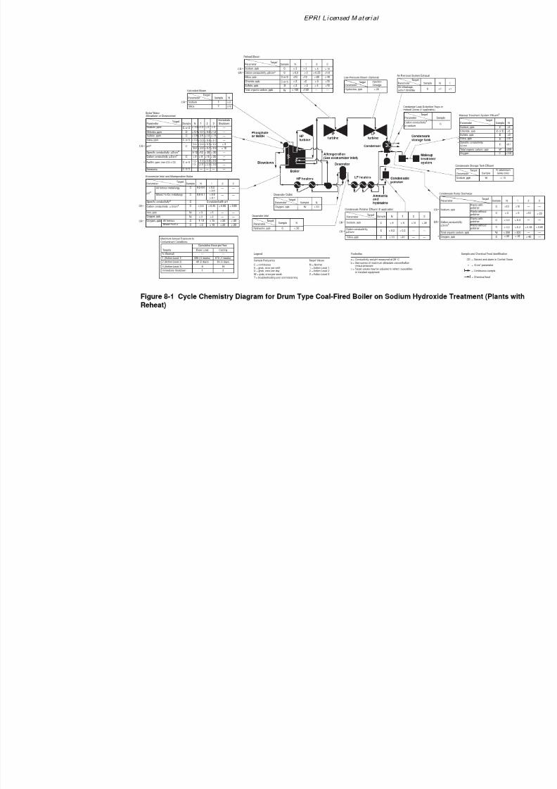
7/18/2019 EPRI Start Up, Lay Up & Shut Down Guidelines for Chemist
http://slidepdf.com/reader/full/epri-start-up-lay-up-shut-down-guidelines-for-chemist 245/256
7/18/2019 EPRI Start Up, Lay Up & Shut Down Guidelines for Chemist
http://slidepdf.com/reader/full/epri-start-up-lay-up-shut-down-guidelines-for-chemist 246/256
Caustic Treatment for Drum Boilers
8-4
As mentioned previously, special care has to be taken to avoid excessively highconcentrations of sodium hydroxide in the boiler water, and carryover of sodiumhydroxide into the steam. This can be prevented by carefully monitoring sodium insteam. The steps used during startup will be plant specific and, depending on thepracticality, the following stages should be monitored, at least during a trial period:
Stage during Startup Circuit Monitoring
a) Addition of hydrazine (if used)andammonia to the feedwater
pH, cation conductivity and oxygen
b) Additional boiler blowdown pH, NaOH or specific conductivity, cationconductivity, chloride, and corrosionproducts
c) Care to avoid additional carryover intosteam
Cation conductivity, silica and sodium
At full load, the values given in the EPRI guidance document(2)
should be achieved.There may be room for relaxation, particularly, as regards silica in steam, duringstartup and the earlier stages of operation and during low load operation, provided theparameters are within the EPRI action levels 1-3, see Figure 8-1. The core parameters,sodium, cation conductivity and oxygen given in the EPRI guidance document
(2) should
be monitored at the condensate pump discharge, condensate polisher outlet (if installed), economizer inlet, boiler water (preferably at downcomer), including pH andspecific conductivity or NaOH, and steam. The normal operating levels, as given in theEPRI guidance document(2), should be achieved as soon as possible. These are given inFigure 8-1.
A road map showing a scheme for startup of a drum boiler with an all-ferrousfeedwater heating system operating with CT is given in Figure 8-2. The time taken toachieve the required target values will be plant dependent. This should be determinedfor each unit, used as guidance for subsequent startups, and amended in the light of operating experience. The procedure can normally be curtailed for warm and hot starts.If the high purity feed and boiler water conditions cannot be maintained duringstartup, it may be necessary to adopt another form of chemical conditioning, such as
phosphate. The Selection and Optimization document provides advice and guidance onthe optimum boiler water and feedwater choices for drum units
(3). The road map,
Figure 8-2, can be divided into 7 steps.
The steps described in Figure 8-2 are essentially similar to those described in Section 6.3for All-Volatile Treatment, except that reference should be made to the CT
(2) guidelines,
instead of the AVT guidelines. Note that additional care is required to avoid excessive
7/18/2019 EPRI Start Up, Lay Up & Shut Down Guidelines for Chemist
http://slidepdf.com/reader/full/epri-start-up-lay-up-shut-down-guidelines-for-chemist 247/256
Caustic Treatment for Drum Boilers
8-5
carryover of boiler water impurities and conditioning chemicals, sodium hydroxide,into the steam.
Under Step 6, excursions affecting (lowering) the pH must be corrected immediately byfeeding 1-2 ppm of sodium hydroxide to the boiler water. Match the sodium hydroxide
to the chloride concentration. Do not overfeed sodium hydroxide. Avoid excesscarryover of boiler water impurities into the steam.
Shutdown
The basic considerations outlined in Section 6.3 for AVT apply during shutdown forCaustic Treatment, with the addition that special care has to be taken to prevent anycarryover of sodium hydroxide from the boiler water, as this could lead to stresscorrosion of austenitic components in the steam circuit.
A road map showing a scheme for shutdown of a drum boiler unit with an all-ferrousfeedwater heating system operating with CT is given in Figure 8-3. The time taken toachieve stable shutdown conditions will be plant dependent. This should bedetermined for each unit, used as guidance for subsequent repeat operations andamended in the light of operating experience. The road map, Figure 8-3, can bedivided into 5 steps.
The steps described in Figure 8-3 are essentially similar to those described in Section 6.3for All-Volatile Treatment, except that reference should be made to the CT
(2) guidelines,
instead of the AVT guidelines. Note that additional care is required to avoid excessivecarryover of boiler water impurities and conditioning chemicals, sodium hydroxide,
into the steam.
Under Steps 4 and 5, excursions affecting (lowering) the pH must be correctedimmediately by feeding 1-2 ppm of sodium hydroxide to the boiler water. Match thesodium hydroxide to the chloride concentration. Do not overfeed sodium hydroxide.Avoid excess carryover of boiler water impurities into the steam.
Again, the steps are essentially similar to those described in Section 5 for phosphatetreatment, except that additional care is required to avoid carryover of boiler waterimpurities and conditioning chemical, sodium hydroxide, into the steam. Control of the
boiler water purity can be achieved by blowdown with drum boilers.
Cycling and Peaking
Essentially, cycling and peaking plant should operate according to the outline givenabove for startup, load changes and shutdown.
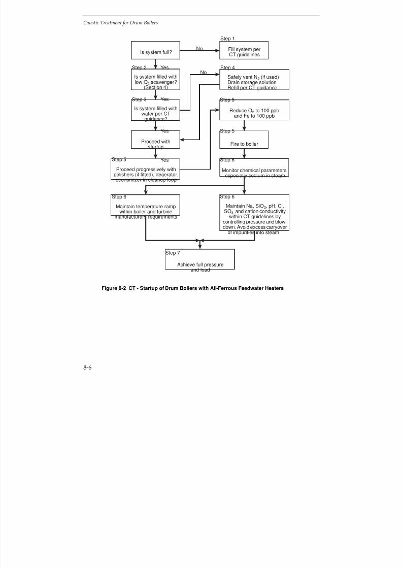
7/18/2019 EPRI Start Up, Lay Up & Shut Down Guidelines for Chemist
http://slidepdf.com/reader/full/epri-start-up-lay-up-shut-down-guidelines-for-chemist 248/256
Caustic Treatment for Drum Boilers
8-6
No
Yes
Step 1
Fill system perCT guidelines
Fire to boiler
Monitor chemical parameters,especially sodium in steam
Achieve full pressureand load
Safely vent N2 (if used)Drain storage solutionRefill per CT guidance
Reduce O2 to 100 ppband Fe to 100 ppb
Maintain Na, SiO2, pH, Cl,SO4 and cation conductivity
within CT guidelines bycontrolling pressure and blow-down. Avoid excess carryover
of impurities into steam
Is system full?
Is system filled withlow O2 scavenger?
(Section 4)
Is system filled withwater per CT
guidance?
Proceed withstartup
Maintain temperature rampwithin boiler and turbine
manufacturers requirements
Proceed progressively withpolishers (if fitted), deaerator,economizer in cleanup loop
Step 4
Step 5
Step 5
Step 6
Step 6Step 6
Step 5
Step 3
Step 2
Yes
Yes
No
Step 7
Yes
Figure 8-2 CT - Startup of Drum Boilers with All-Ferrous Feedwater Heaters
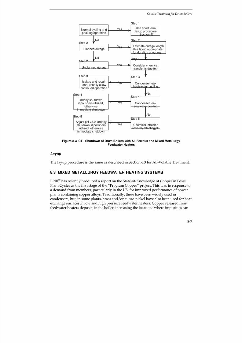
7/18/2019 EPRI Start Up, Lay Up & Shut Down Guidelines for Chemist
http://slidepdf.com/reader/full/epri-start-up-lay-up-shut-down-guidelines-for-chemist 249/256
Caustic Treatment for Drum Boilers
8-7
Estimate outage length.Use layup appropriatefor duration of outage
No
Step 1
Use short termlayup procedure
(Section 4)
Isolate and repairleak, usually allow
continued operation
Step 2
Step 3
Step 3
Step 2
Yes
Consider chemicaltransients due to:-
Orderly shutdown,if polishers utilized,
otherwiseimmediate shutdown
Normal cycling andpeaking operation
Unplanned outage
Yes
Yes
Yes
Yes
Condenser leakfresh water cooling
Condenser leaksea water cooling
Planned outage
Step 4
Step 2
No
No
Step 3
Step 4
Step 5Step 5
Adjust pH >8.0, orderlyshutdown, if polishers
utilized, otherwiseimmediate shutdown
Yes Chemical intrusionseverely affecting pH
No
Figure 8-3 CT - Shutdown of Drum Boilers with All-Ferrous and Mixed MetallurgyFeedwater Heaters
Layup
The layup procedure is the same as described in Section 6.3 for All-Volatile Treatment.
8.3 MIXED METALLURGY FEEDWATER HEATING SYSTEMS
EPRI(4)
has recently produced a report on the State-of-Knowledge of Copper in Fossil
Plant Cycles as the first stage of the “Program Copper” project. This was in response toa demand from members, particularly in the US, for improved performance of powerplants containing copper alloys. Traditionally, these have been widely used incondensers, but, in some plants, brass and/or cupro-nickel have also been used for heatexchange surfaces in low and high pressure feedwater heaters. Copper released fromfeedwater heaters deposits in the boiler, increasing the locations where impurities can
7/18/2019 EPRI Start Up, Lay Up & Shut Down Guidelines for Chemist
http://slidepdf.com/reader/full/epri-start-up-lay-up-shut-down-guidelines-for-chemist 250/256
Caustic Treatment for Drum Boilers
8-8
concentrate on boiler waterwalls. Thick deposits can lead to overheating and thepresence of copper in deposits complicates chemical cleaning.
Copper in high pressure boilers can be carried over into the steam and deposited onhigh pressure turbines, where even as little as 1 kg can reduce the output capacity of
the turbine by 1 MW. This is particularly true for plants operating at more than 2400 psi(16.6 MPa) and is exacerbated further by increasing pressure. The presence of oxygenand the absence of reducing conditions in the feedwater is the main cause of coppertransport around the circuit.
It is worth reiterating(4)
that startups are generally considered to be the periods of maximum copper transport activity in the cycle. This relates directly to the feedwatersystem not being protected during shutdown periods, i.e. that a reducing environment(ORP < 0mV) is not maintained. Air in-leakage into the LP feedwater circuits increasesthe growth of non-protective copper oxides and copper transport. The EPRI
(4) “Guiding
Principles” for successful operation of units with copper alloys are:
Keep feedwater copper levels at guideline values (< 2 ppb at the economizer inlet)during normal operation.
Establish conditions which favor cuprous oxide (Cu2O) rather than cupric oxide(CuO) under all operating conditions.
Maintain reducing chemistry (oxidizing-reducing potential, ORP < 0mV) at alltimes, including shutdown and startup.
Control feedwater pH in the range 8.8-9.1.
Implement shutdown procedures and layup programs which effectively minimizecopper transport activity upon return to service.
Consider volatility effects in controlling drum pressure; if possible, maximizeoperating pressure in the range of 2400-2500 psi (16.5-17.2 MPa) and avoid over-pressure operation above this range.
Many of the features discussed in Section 6 on All-Volatile Treatment also apply toCaustic Treatment, with the proviso that particular care has to be taken in controlling
the concentration of sodium hydroxide in the boiler water and carry over into thesteam. This Section 8.3 of the guidlines will concentrate on the additionalconsiderations for Caustic Treatment and mixed Fe-Cu metallurgy feedwater heatingsystems.
7/18/2019 EPRI Start Up, Lay Up & Shut Down Guidelines for Chemist
http://slidepdf.com/reader/full/epri-start-up-lay-up-shut-down-guidelines-for-chemist 251/256
Caustic Treatment for Drum Boilers
8-9
Current Guidelines
The current guidance on caustic treatment for drum boilers with mixed Fe-Cumetallurgy feedwater systems are given in Figure 8-1 for reheat plants, including the“core” parameters. The normal limits and three action levels for sodium, chloride,
sulfate, copper, silica and cation conductivity in boiler water are given in the EPRI(2)
report on Sodium Hydroxide Conditioning the Boiler Water of Drum-Type Boilers.Non-reheat plant were not considered.
Startup
The basic considerations outlined in Section 6.4 for AVT with mixed Fe-Cu metallurgyfeedwater heating systems, also apply during startup for Caustic Treatment, with theaddition that special care has to be taken to prevent any carryover of sodium hydroxidein the boiler water, as this could lead to stress corrosion of austenitic components in the
steam circuit. Care is required to minimise the ingress of oxygen to reduce thecorrosion of copper alloys.
The presence of oxygen also assists the transport of copper into the steam, increasingthe risk of deposition in the superheater and high pressure turbine. It is also importantto ensure that the pH, cation conductivity and chloride concentration are within thelimits given in the EPRI
(2) guidance document for boiler water. Hydrazine (or volatile
reducing agents) should not be eliminated from plants with mixed Fe-Cu feedwatersystems.
As mentioned previously, special care has to be taken to avoid excessively high
concentrations of sodium hydroxide in the boiler water and carryover of sodiumhydroxide into the steam. This can be prevented by carefully monitoring sodium insteam. The steps used during startup will be plant specific and, depending on thepracticality, the following stages should be monitored, at least during a trial period:
Stage during Startup Circuit Monitoring
a) Addition of hydrazine and ammonia tothe feedwater
pH, cation conductivity, oxygen andcopper
b) Additional boiler blowdown pH, NaOH or specific conductivity, cationconductivity, chloride, and corrosionproducts
c) Care to avoid additional carryover intosteam
Cation conductivity, silica, sodium andcopper
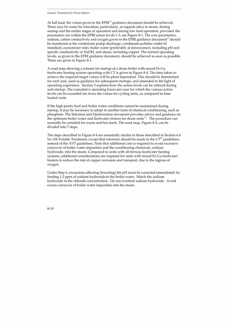
7/18/2019 EPRI Start Up, Lay Up & Shut Down Guidelines for Chemist
http://slidepdf.com/reader/full/epri-start-up-lay-up-shut-down-guidelines-for-chemist 252/256
Caustic Treatment for Drum Boilers
8-10
At full load, the values given in the EPRI(2)
guidance document should be achieved.There may be room for relaxation, particularly, as regards silica in steam, duringstartup and the earlier stages of operation and during low load operation, provided theparameters are within the EPRI action levels 1-3, see Figure 8-1. The core parameters,sodium, cation conductivity and oxygen given in the EPRI guidance document
(2) should
be monitored at the condensate pump discharge, condensate polisher outlet (if installed), economizer inlet, boiler water (preferably at downcomer), including pH andspecific conductivity or NaOH, and steam, including copper. The normal operatinglevels, as given in the EPRI guidance document, should be achieved as soon as possible.These are given in Figure 8-1.
A road map showing a scheme for startup of a drum boiler with mixed Fe-Cufeedwater heating system operating with CT is given in Figure 8-4. The time taken toachieve the required target values will be plant dependent. This should be determinedfor each unit, used as guidance for subsequent startups, and amended in the light of operating experience. Section 3 explains how the action levels can be utilized duringunit startup. The cumulative operating hours per year for which the various actionlevels can be exceeded are twice the values for cycling units, as compared to baseloaded units.
If the high purity feed and boiler water conditions cannot be maintained duringstartup, it may be necessary to adopt to another form of chemical conditioning, such asphosphate. The Selection and Optimization document provides advice and guidance onthe optimum boiler water and feedwater choices for drum units
(3). The procedure can
normally be curtailed for warm and hot starts. The road map, Figure 8-4, can bedivided into 7 steps.
The steps described in Figure 8-4 are essentially similar to those described in Section 6.4for All-Volatile Treatment, except that reference should be made to the CT(2) guidelines,instead of the AVT guidelines. Note that additional care is required to avoid excessivecarryover of boiler water impurities and the conditioning chemicals, sodiumhydroxide, into the steam. Compared to units with all-ferrous feedwater heatingsystems, additional considerations are required for units with mixed Fe-Cu feedwaterheaters to reduce the risk of copper corrosion and transport, due to the ingress of oxygen.
Under Step 6, excursions affecting (lowering) the pH must be corrected immediately byfeeding 1-2 ppm of sodium hydroxide to the boiler water. Match the sodiumhydroxide to the chloride concentration. Do not overfeed sodium hydroxide. Avoidexcess carryover of boiler water impurities into the steam.
7/18/2019 EPRI Start Up, Lay Up & Shut Down Guidelines for Chemist
http://slidepdf.com/reader/full/epri-start-up-lay-up-shut-down-guidelines-for-chemist 253/256
Caustic Treatment for Drum Boilers
8-11
No
Yes
Step 2
Fill system perCT guidelines
Fire to boiler
Achieve full pressureand load
Safely vent N2 (if used)Drain storage solutionRefill per CT guidelines
Add N2H4, if necessary.Reduce O2 to 100 ppb, Feto 100 ppb, Cu to 10 ppb
Maintain Cu, Na, SiO2, pH, Cl,SO4 and cation conductivity
within CT guidelines bycontrolling pressure and blow-down. Avoid excess carryover
of impurities into steam
Is system full?
Is system filled withlow O2 scavenger?
(Section 4)
Is system filled withwater per CTguidelines?
Proceed withstartup
Maintain temperature rampwithin boiler and turbine
manufacturers requirements
Proceed progressively withpolishers (if fitted), deaerator,economizer in cleanup loop
Step 4
Step 5
Step 5
Step 6
Step 6Step 6
Step 5
Step 3
Step 2
Yes
Yes
No
Step 12
Monitor chemical parameters,especially sodium in steam
Yes
Figure 8-4 CT - Startup of Drum Boilers with Mixed Fe-Cu Metallurgy FeedwaterHeaters
Shutdown
Information is given in Section 4 on the procedures generally applicable to shutdown,and below for various planned shutdown conditions.
The basic considerations outlined in Section 6.4 for AVT with mixed Fe-Cu metallurgyfeedwater systems, also apply during shutdown for Caustic Treatment, with the
7/18/2019 EPRI Start Up, Lay Up & Shut Down Guidelines for Chemist
http://slidepdf.com/reader/full/epri-start-up-lay-up-shut-down-guidelines-for-chemist 254/256
Caustic Treatment for Drum Boilers
8-12
addition that special care has to be taken to prevent any carryover of sodium hydroxidefrom the boiler water, as this could lead to stress corrosion of austenitic components inthe steam circuit. Care is required to minimise the ingress of oxygen to reduce thecorrosion of copper alloys.
A road map showing a scheme for shutdown of a drum boiler an with mixed Fe-Cufeedwater heating system operating with CT is given in Figure 8-3. The time taken toachieve stable shutdown conditions will be plant dependent. This should bedetermined for each unit, used as guidance for subsequent repeat operations andamended in the light of operating experience. The road map, Figure 8-3, can be dividedinto 5 steps.
The steps described in Figure 8-3 are essentially similar to those described in Section 6.for All-Volatile Treatment, except that reference should be made to the CT(2) guidelines,instead of the AVT guidelines. Note that additional care is required to avoid excessivecarryover of boiler water impurities and the conditioning chemicals, sodiumhydroxide, into the steam. Compared to units with all-ferrous feedwater heatingsystems, additional considerations are required for units with mixed Fe-Cu feedwaterheaters to reduce the risk of copper corrosion and transport, due to the ingress of oxygen.
Under Steps 4 and 5, excursions affecting (lowering) the pH must be correctedimmediately by feeding 1-2 ppm of sodium hydroxide to the boiler water. Match thesodium hydroxide to the chloride concentration. Do not overfeed sodium hydroxide.Avoid excess carryover of boiler water impurities into the steam.
Cycling and Peaking
Essentially, cycling and peaking plant should operate according to the outline givenabove for startup, load changes and shutdown.
Layup
The layup procedure is the same as described in Section 6.4 for All-Volatile Treatment.
8.4 REFERENCES
1. Cycle Chemistry Guidelines for Fossil Plants: All-Volatile Treatment. Electric PowerResearch Institute, Palo Alto, Calif. EPRI TR-105041. April 1996
2. Sodium Hydroxide for Conditioning the Boiler Water of Drum-Type Boilers. ElectricPower Research Institute, Palo Alto, Calif. EPRI TR-105041. April 1996

7/18/2019 EPRI Start Up, Lay Up & Shut Down Guidelines for Chemist
http://slidepdf.com/reader/full/epri-start-up-lay-up-shut-down-guidelines-for-chemist 255/256
Caustic Treatment for Drum Boilers
8-13
3. Selection and Optimization of Boiler and Feedwater Treatment for Fossil Plants. ElectricPower Research Institute, Palo Alto, Calif. EPRI TR-105040. March 1997
4. State of Knowledge of Copper in Fossil Plant Cycles. Electric Power Research Institute,Palo Alto, Calif. EPRI TR-108460, September 1997

7/18/2019 EPRI Start Up, Lay Up & Shut Down Guidelines for Chemist
http://slidepdf.com/reader/full/epri-start-up-lay-up-shut-down-guidelines-for-chemist 256/256