Embed Size (px)
DESCRIPTION
Instruction manual for EPRC10-EC 12/24 Volt Solar Charge Controller by EPSolar Beijing.
Citation preview
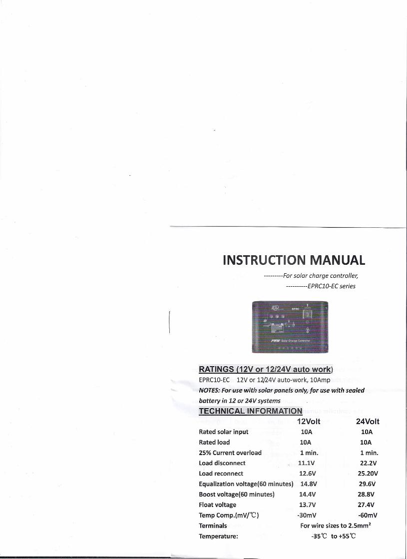
25% Current overload
Load disconnect
Load reconnect
Equalization voltage(60 minutes)
Boost voltage(60 minutes)
Float voltage
Temp Comp.(mVrC)
Terminals
Temperature:
lmin.
11.lV
l2.6V
l4.8V
l4.4V
13.7V
-30mV
24VoltlOA
lOA
lmin.
22.2V
25.20V
29.6V
28.8V
27.4V
-60mV
INSTRUCTION MANUAL---------For solar charge controller;
----------EPRC10-EC series
RATINGS (12V or 12/24V auto work)EPRClO-EC 12V or 12/24V auto-work, lOAmp
NOTES:For use with solar panels only, for use with sealed
battery in 12 or 24V systems
TECHNICAL INFORMATION12Volt
lOA
lOA
Rated solar input
Rated load
For wire sizes to 2.5mm2
-35·C to +55·C
QUICK START INSTRUCTIONSThis section provides a brief overview of how to get started
using the controller. However, please review the entire manual
to ensure best performance and years of trouble-free service.
1. Mount the controller to a vertical surface. Allow space
above and below the controller for air flow.
2. Make sure the PV and load currents will not exceed the
ratings of the controller being installed.
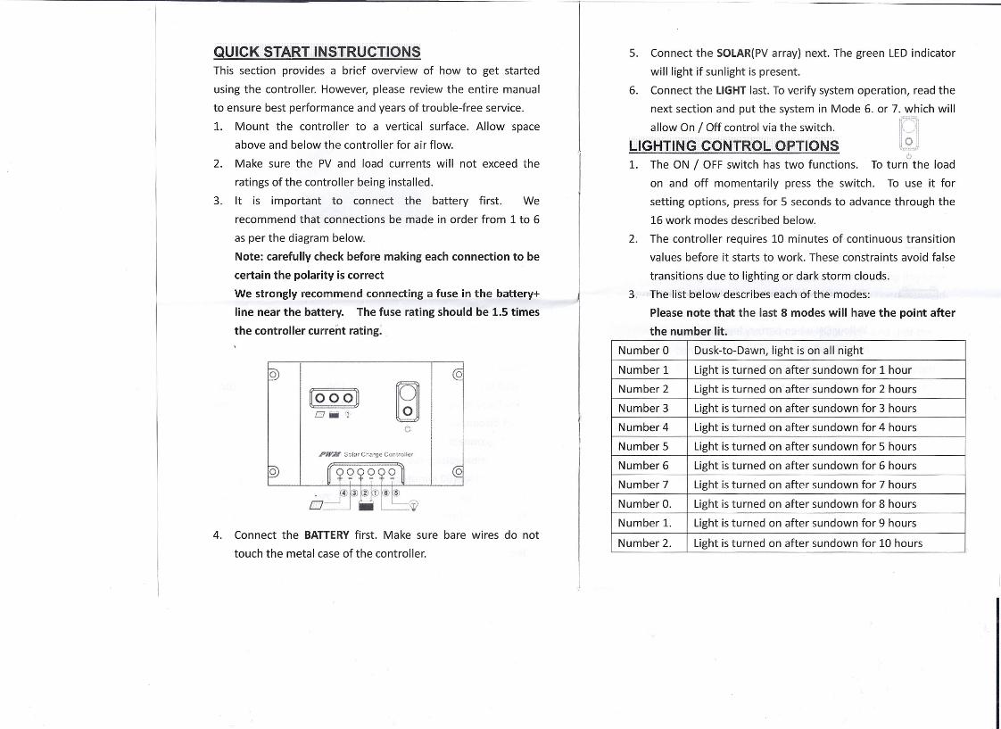
3. It is important to connect the battery first. We
recommend that connections be made in order from 1 to 6
as per the diagram below.
Note: carefully check before making each connection to be
certain the polarity is correct
We strongly recommend connecting a fuse in the battery+
line near the battery. The fuse rating should be 1.5 times
the controller current rating ..
~ooo~Oiili (!
oo
FirM' Solar Charge Controller
4. Connect the BATTERYfirst. Make sure bare wires do not
touch the metal case of the controller.
5. Connect the SOLAR(PVarray) next. The green LED indicator
will light if sunlight is present.
6. Connect the LIGHT last. To verify system operation, read the
next section and put the system in Mode 6. or 7. which will
LlGa~~~:~/ ~~~o;~~~a~~;;~~hS [~]6
1. The ON / OFF switch has two functions. To turn the load
on and off momentarily press the switch. To use it for
setting options, press for 5 seconds to advance through the
16 work modes described below.
2. The controller requires 10 minutes of continuous transition
values before it starts to work. These constraints avoid false
transitions due to lighting or dark storm clouds.
3. The list below describes each of the modes:
Please note that the last 8 modes will have the point after
the number lit.
Number 0 Dusk-to-Dawn, light is on all night
Number 1 Light is turned on after sundown for 1 hour
Number 2 Light is turned on after sundown for 2 hours
Number 3 Light is turned on after sundown for 3 hours
Number 4 Light is turned on after sundown for 4 hours
Number 5 Light is turned on after sundown for 5 hours
Number 6 Light is turned on after sundown for 6 hours
Number 7 Light is turned on after sundown for 7 hours
Number O. Light is turned on after sundown for 8 hours
Number 1. Light is turned on after sundown for 9 hours
Number 2. Light is turned on after sundown for 10 hours
Number 3.
Number 4.
Number 5.
Number 6.
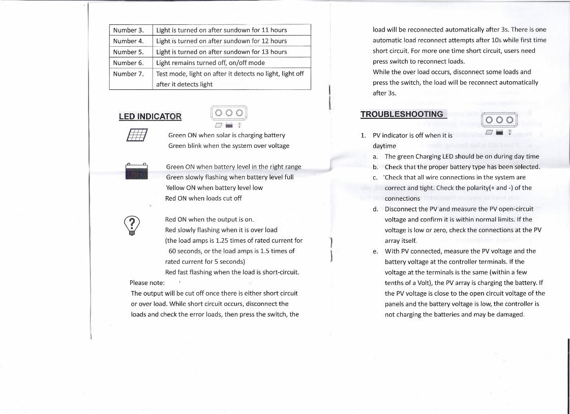
Light is turned on after sundown for 11 hours----1
Light is turned on after sundown for 12 hours----1
Light is turned on after sundown for 13 hours-----I
Light remains turned off, on/off mode
Number 7. Test mode, light on after it detects no light, light off
after it detects light
[:0 0 o:~OWZ
Green ON when solar is charging battery
Green blink when the system over voltage
LED INDICATOR
lllllGreen ON when battery level in the right range
Green slowly flashing when battery level full
Yellow oN when battery level low
Red ON when loads cut off
Red ON when the output is on.
Red slowly flashing when it is over load
(the load amps is 1.25 times of rated current for
60 seconds, or the load amps is 1.5 times of
rated current for 5 seconds)
Red fast flashing when the load is short-circuit.
Please note:
The output will be cut off once there is either short circuit
or over load. While short circuit occurs, disconnect the
loads and check the error loads, then press the switch, the
1I
load will be reconnected automatically after 3s. There is one
automatic load reconnect attempts after 10s while first time
short circuit. For more one time short circuit, users need
press switch to reconnect loads.
While the over load occurs, disconnect some loads and
press the switch, the load will be reconnect automatically
after 3s.
TROUBLESHOOTING [:0 0 O:~o -Z1. PV indicator is off when it is
daytime
a. The green Charging LEDshould be on during day time
b. Check that the proper battery type has been selected.
c. 'Check that all wire connections in the system are
correct and tight. Check the polarity(+ and -) of the
connections
d. Disconnect the PV and measure the PVopen-circuit
voltage and confirm it is within normal limits. If the
voltage is low or zero, check the connections at the PV
array itself.
e. With PV connected, measure the PV voltage and the
battery voltage at the controller terminals. If the
voltage at the terminals is the same (within a few
tenths of a Volt), the PV array is charging the battery. If
the PV voltage is close to the open circuit voltage of the
panels and the battery voltage is low, the controller is
not charging the batteries and may be damaged.
2. Charging LEDindicator is blinking
a. First check the operating conditions to confirm that the
voltage is higher than specifications. Consider the
temperature compensation of the controller's PWM
setpoint. If the temperature lower than o·c the
controller will regulate higher than 17V(17V is over
voltage point).
b. Check that all wire connections in the system are
correct and tight.
3. Problems with operation of load
a. If Load LEDis fast flashing, there is a short circuit.
Look for short circuit.
b. If Load LEDis slow flashing, there is an overload
condition. Check wiring to load, check connections.
If you have multiple devices connected to the load, you
may need to measure the current of each device to find
defective device. Reduce the load, and press the
switch button, the controller will turn on load after 30
seconds.
c. If load is not operating, check that the load is turned on.
Check that no system fuses are defective. Check
connections to the load, and other controller and
battery connections. Make sure voltage drops in the
system wires 'are not too high.
Ii,
INSPECTION AND MAINTENANCEThe following inspections and maintenance tasks are
recommended at least once per year for best controller
performance
1. Confirm that the current levels of the solar array and load
do not exceed the controller ratings.
2. Tighten all the terminals. Inspect for loose, broken, or burnt
wire connections. Be certain no loose strands of wire are
touching other terminals
3. Verify the lights are working. This can be tested by putting
controller in mode 18 or 19 and using the button as an
on/off switch.
4. Check that the controller is securely mounted in a clean
environment. Inspect for dirt, insects and corrosion.
S. Check the air flow around the controller is not blocked.
6. Protect from sun and rain. Confirm that water is not
collecting under the cover
7. Check that the controller functions and LED indicators are
correct for the system conditions at that time.
8. Make sure the PV array is clean and clear of debris and snow.
Confirm the array is oriented correctly for the installation
location.
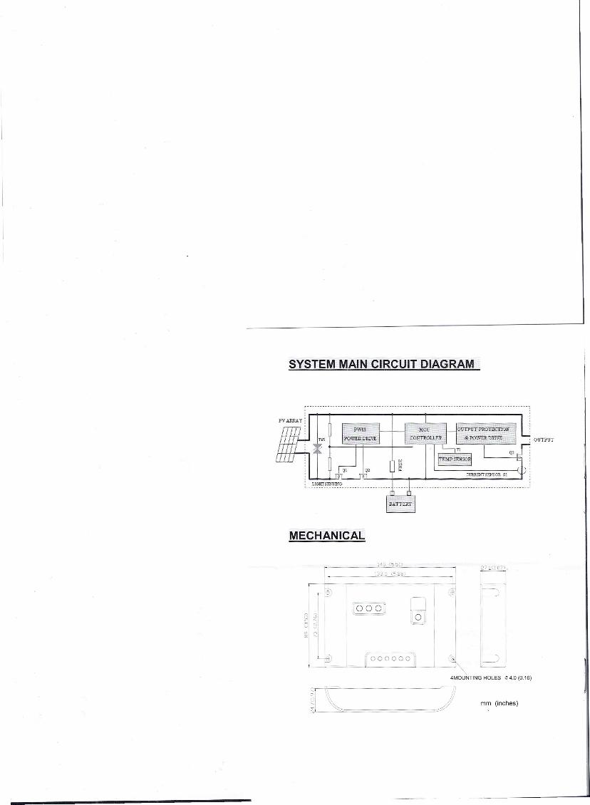
SYSTEM MAIN CIRCUIT DIAGRAM
OUTPUT
------------------- ---------_.---------------------------------------- --_.-----------
ill 1 1 I
I~TTE~ I
MECHANICAL
, --'140 (55j)
r_ 133:; (5~ _272(1.07)1--1
,-- ~~~ @' ~--,Ir --' I
~. ~-~ ,:;1 ~
(:000'L= ..==!J
'-1~23
II 1
~,
g;! ~I
, Lf? ~~ ~J~I0 0 0 000 Ii-~1 ----=cJ "'- HOLEStt4.0 (0.16)
4MOUNTING
~<::'-= -~~I~ mm (inches)