Embed Size (px)
Citation preview

Episode 3. Principles in Network Design
Baochun Li Department of Electrical and Computer Engineering
University of Toronto
Part 2

ECE 1771: Quality of Service — Baochun Li, Department of Electrical and Computer Engineering, University of Toronto
Recall: Designing the network as a system
Last episode: Every complex computer system involves one or more communication links, usually organized to form a network
Identified challenging properties of a network The layering principle: the three-layer reference design The end-to-end argument: applications know the best!
2

ECE 1771: Quality of Service — Baochun Li, Department of Electrical and Computer Engineering, University of Toronto
But there are more of these principles
(techniques) in design

ECE 1771: Quality of Service — Baochun Li, Department of Electrical and Computer Engineering, University of Toronto
Reading: Keshav 6.1 — 6.5, Salzer 7.3 — 7.4

ECE 1771: Quality of Service — Baochun Li, Department of Electrical and Computer Engineering, University of Toronto
What is system design?
A computer network provides computation, storage and transmission resources
System design is the art and science of putting together these resources into a harmonious whole
Extract the most from what you have
5

ECE 1771: Quality of Service — Baochun Li, Department of Electrical and Computer Engineering, University of Toronto
Performance metrics and resource constraints
6

ECE 1771: Quality of Service — Baochun Li, Department of Electrical and Computer Engineering, University of Toronto
Performance metrics and resource constraints
In any system, some resources are more freely available than others
6

ECE 1771: Quality of Service — Baochun Li, Department of Electrical and Computer Engineering, University of Toronto
Performance metrics and resource constraints
In any system, some resources are more freely available than others
Think about a high-end laptop connected to Internet by a DSL modem
6

ECE 1771: Quality of Service — Baochun Li, Department of Electrical and Computer Engineering, University of Toronto
Performance metrics and resource constraints
In any system, some resources are more freely available than others
Think about a high-end laptop connected to Internet by a DSL modem
The constrained resource is link bandwidth
CPU and and memory are unconstrained
We wish to maximize a set of performance metrics given a set of resource constraints
Explicitly identifying constraints and metrics helps in designing efficient systems — e.g., maximize reliability and MPG for a car that costs less than $10,000 to manufacture
6

ECE 1771: Quality of Service — Baochun Li, Department of Electrical and Computer Engineering, University of Toronto
Real-world system design
7

ECE 1771: Quality of Service — Baochun Li, Department of Electrical and Computer Engineering, University of Toronto
Real-world system design
Criteria such as scalability, modularity, extensibility, and elegance are important, but unquantifiable
7

ECE 1771: Quality of Service — Baochun Li, Department of Electrical and Computer Engineering, University of Toronto
Real-world system design
Criteria such as scalability, modularity, extensibility, and elegance are important, but unquantifiable
Rapid technological change can add or remove resource constraints
an ideal design is ‘future proof’
Market conditions may dictate changes to design halfway through the process
International standards, which themselves change, also impose constraints
Nevertheless, still possible to identify some principles
7

ECE 1771: Quality of Service — Baochun Li, Department of Electrical and Computer Engineering, University of Toronto
Most resources are a combination of time, space, computation,
money, labor, and scaling

ECE 1771: Quality of Service — Baochun Li, Department of Electrical and Computer Engineering, University of Toronto
Time
9

ECE 1771: Quality of Service — Baochun Li, Department of Electrical and Computer Engineering, University of Toronto
Time
Shows up in many constraints
9

ECE 1771: Quality of Service — Baochun Li, Department of Electrical and Computer Engineering, University of Toronto
Time
Shows up in many constraints
deadline for task completion
9

ECE 1771: Quality of Service — Baochun Li, Department of Electrical and Computer Engineering, University of Toronto
Time
Shows up in many constraints
deadline for task completion
time to market
9

ECE 1771: Quality of Service — Baochun Li, Department of Electrical and Computer Engineering, University of Toronto
Time
Shows up in many constraints
deadline for task completion
time to market
mean time between failures
9

ECE 1771: Quality of Service — Baochun Li, Department of Electrical and Computer Engineering, University of Toronto
Time
Shows up in many constraints
deadline for task completion
time to market
mean time between failures
Metrics
9

ECE 1771: Quality of Service — Baochun Li, Department of Electrical and Computer Engineering, University of Toronto
Time
Shows up in many constraints
deadline for task completion
time to market
mean time between failures
Metrics
response time: mean time to complete a task
9

ECE 1771: Quality of Service — Baochun Li, Department of Electrical and Computer Engineering, University of Toronto
Time
Shows up in many constraints
deadline for task completion
time to market
mean time between failures
Metrics
response time: mean time to complete a task
throughput: number of tasks completed per unit time
degree of parallelism = response time * throughput
20 tasks complete in 10 seconds, and each task takes 3 seconds
=> degree of parallelism = 3 * 20/10 = 6
9

ECE 1771: Quality of Service — Baochun Li, Department of Electrical and Computer Engineering, University of Toronto
Space
Example: a limit on the memory available to hold packets in switches and routers
We can also view bandwidth as a “space” constraint
A T3 link has a bandwidth of 44.768 Mbps. If we use it to carry video streams with a mean bit rate of 1.5 Mbps, we can fit at most 29 streams in the link
10

ECE 1771: Quality of Service — Baochun Li, Department of Electrical and Computer Engineering, University of Toronto
Scaling
A design constraint, rather than a resource constraint
Minimizes the use of centralized elements in the design
forces the use of complicated distributed algorithms
Hard to measure
but necessary for success
11

ECE 1771: Quality of Service — Baochun Li, Department of Electrical and Computer Engineering, University of Toronto
Common design techniques
12

ECE 1771: Quality of Service — Baochun Li, Department of Electrical and Computer Engineering, University of Toronto
Common design techniques
Key concept: bottleneck
12

ECE 1771: Quality of Service — Baochun Li, Department of Electrical and Computer Engineering, University of Toronto
Common design techniques
Key concept: bottleneck
the most constrained element in a system
12

ECE 1771: Quality of Service — Baochun Li, Department of Electrical and Computer Engineering, University of Toronto
Common design techniques
Key concept: bottleneck
the most constrained element in a system
System performance improves by removing the bottleneck
12

ECE 1771: Quality of Service — Baochun Li, Department of Electrical and Computer Engineering, University of Toronto
Common design techniques
Key concept: bottleneck
the most constrained element in a system
System performance improves by removing the bottleneck
but creates new bottlenecks
12
ECE 1771: Quality of Service — Baochun Li, Department of Electrical and Computer Engineering, University of Toronto
Common design techniques
Key concept: bottleneck
the most constrained element in a system
System performance improves by removing the bottleneck
but creates new bottlenecks
In a balanced system, all resources are simultaneously bottlenecked
12

ECE 1771: Quality of Service — Baochun Li, Department of Electrical and Computer Engineering, University of Toronto
Common design techniques
Key concept: bottleneck
the most constrained element in a system
System performance improves by removing the bottleneck
but creates new bottlenecks
In a balanced system, all resources are simultaneously bottlenecked
this is optimal, but nearly impossible to achieve
in practice, bottlenecks move from one part of the system to another
example: Ford Model T
12

ECE 1771: Quality of Service — Baochun Li, Department of Electrical and Computer Engineering, University of Toronto
Top level objective
Use unconstrained resources to alleviate bottleneck
But how do we do this?
Here are several common design techniques that help us to tradeoff one resource for another
13

ECE 1771: Quality of Service — Baochun Li, Department of Electrical and Computer Engineering, University of Toronto
Multiplexing
Another word for sharing
Trades time and space for money
Users see an increased response time, and take up space when waiting, but the system costs less
economies of scale make a single large resource cheaper
14

ECE 1771: Quality of Service — Baochun Li, Department of Electrical and Computer Engineering, University of Toronto
Multiplexing
Examples
multiplexed communication links
cloud computing
Another way to look at a shared resource
unshared virtual resource
Server controls access to the shared resource
uses a schedule to resolve contention
choice of scheduling: critical in proving quality of service guarantees (think about boarding a flight)
15

ECE 1771: Quality of Service — Baochun Li, Department of Electrical and Computer Engineering, University of Toronto
Statistical Multiplexing
Suppose resource has capacity C
Shared by N identical tasks
Each task requires capacity c
If Nc <= C, then the resource is underloaded
If at most 10% of tasks active, then C >= Nc/10 is enough
we have used statistical knowledge of users to reduce system cost
this is the statistical multiplexing gain
16

ECE 1771: Quality of Service — Baochun Li, Department of Electrical and Computer Engineering, University of Toronto
Two types of statistical multiplexing
Two types: spatial and temporal
Spatial
we expect only a fraction of tasks to be simultaneously active
Temporal
we expect a task to be active only part of the time — its average resource consumption is less than its peak
e.g. silence periods during a voice call; video streams with variable bit rates
17

ECE 1771: Quality of Service — Baochun Li, Department of Electrical and Computer Engineering, University of Toronto
Parallelism: trading computation for time
18

ECE 1771: Quality of Service — Baochun Li, Department of Electrical and Computer Engineering, University of Toronto
Parallelism: trading computation for time
Suppose you wanted to complete a task in less time
18

ECE 1771: Quality of Service — Baochun Li, Department of Electrical and Computer Engineering, University of Toronto
Parallelism: trading computation for time
Suppose you wanted to complete a task in less time
Could you use more processors to do so?
18

ECE 1771: Quality of Service — Baochun Li, Department of Electrical and Computer Engineering, University of Toronto
Parallelism: trading computation for time
Suppose you wanted to complete a task in less time
Could you use more processors to do so?
Yes, if you can break up the task into independent subtasks
such as downloading images into a browser
optimal if all subtasks take the same time
What if subtasks are dependent?
for instance, a subtask may not begin execution before another ends
such as in the iPhone assembly line
Then, having more processors doesn’t always help
18

ECE 1771: Quality of Service — Baochun Li, Department of Electrical and Computer Engineering, University of Toronto
Pipelining
Special case of serially dependent subtasks: a subtask depends only on the previous one in execution chain
19

ECE 1771: Quality of Service — Baochun Li, Department of Electrical and Computer Engineering, University of Toronto
Batching: trading response time for throughput
Group tasks together to amortize overhead
Only works when overhead for N tasks < N time overhead for one task
Also, time taken to accumulate a batch shouldn’t be too long
We’re getting reduced overhead and increased throughput, but suffering from a longer worst case response time
20

ECE 1771: Quality of Service — Baochun Li, Department of Electrical and Computer Engineering, University of Toronto
Hierarchy
Recursive decomposition of a system into smaller pieces that depend only on their parent for proper execution
No single point of control
Highly scalable
Leaf-to-leaf communication can be expensive: shortcuts help
21

ECE 1771: Quality of Service — Baochun Li, Department of Electrical and Computer Engineering, University of Toronto
Randomization
Allows us to break a tie fairly
A powerful tool
Examples
resolving contention in a broadcast medium
randomized routing
choosing multicast timeouts
22

ECE 1771: Quality of Service — Baochun Li, Department of Electrical and Computer Engineering, University of Toronto
Soft State
State: memory in the system that influences future behaviour
VCI translation table in ATM networks
Problem: needs to create and remove it explicitly
The idea of soft state: remove on a timer
If you want to keep it, refresh
Automatically cleans up after a failure
Trades bandwidth and computation for robustness and simpler system design
23

ECE 1771: Quality of Service — Baochun Li, Department of Electrical and Computer Engineering, University of Toronto
Separating data and control planes
Divide actions that happen once per connection from actions that happen once per packet
Data path: per-packet actions
Control path: Actions not in the data path
Can increase throughput by minimizing actions in data path
Examples
connection-oriented (ATM) networks
Software-defined networking (SDN)
On the other hand, keeping control information in data element has its advantages: more resilient to failures with less state, and per-packet Quality of Service
24

ECE 1771: Quality of Service — Baochun Li, Department of Electrical and Computer Engineering, University of Toronto
How are design principles applied?
In each of the three layers:
The link layer The network layer The end-to-end layer
25

ECE 1771: Quality of Service — Baochun Li, Department of Electrical and Computer Engineering, University of Toronto
Design Principles in the Link Layer

ECE 1771: Quality of Service — Baochun Li, Department of Electrical and Computer Engineering, University of Toronto
Transmitting digital data in an analog world
27

ECE 1771: Quality of Service — Baochun Li, Department of Electrical and Computer Engineering, University of Toronto
Transmitting digital data in an analog world
The link layer is responsible for moving data bits from one physical location to another
27

ECE 1771: Quality of Service — Baochun Li, Department of Electrical and Computer Engineering, University of Toronto
Transmitting digital data in an analog world
The link layer is responsible for moving data bits from one physical location to another
If we are just talking about moving a bit from one register to another on the same chip (or even on the same PCB), we can —
Run a wire that connects the output of the first register to the input of the next
Wait till the first register’s output has settled and the signal has propagated to the input of the second
The next clock tick reads the data into the second register
27

ECE 1771: Quality of Service — Baochun Li, Department of Electrical and Computer Engineering, University of Toronto
Assumptions for this to work
Three assumptions for this to work —
All of the voltages are within their specified tolerances
Clock ticks are separated enough in time to allow for the propagation
There is no electrical interference
These do not hold if we send bits across the room—modules do not share the same clock!
But a three-wire ready/acknowledge protocol may work effectively
28
Saltzer & Kaashoek Ch. 7, p. 35 June 25, 2009 8:22 am
7.3 The Link Layer 7–35
ages are within their specified tolerances, the clock ticks are separated enough in time toallow for the propagation, and there is no electrical interference, then that is all there isto it.
Maintaining those three assumptions is relatively easy within a single chip, and evenbetween chips on the same printed circuit board. However, as we begin to consider send-ing bits between boards, across the room, or across the country, these assumptionsbecome less and less plausible, and they must be replaced with explicit measures to ensurethat data is transmitted accurately. In particular, when the sender and receiver are in sep-arate systems, providing a correctly timed clock signal becomes a challenge.
A simple method for getting data from one module to another module that does notshare the same clock is with a three-wire (plus common ground) ready/acknowledge pro-tocol, as shown in figure 7.20. Module A, when it has a bit ready to send, places the biton the data line, and then changes the steady-state value on the ready line. When B seesthe ready line change, it acquires the value of the bit on the data line, and then changesthe acknowledge line to tell A that the bit has been safely received. The reason that theready and acknowledge lines are needed is that, in the absence of any other synchronizingscheme, B needs to know when it is appropriate to look at the data line, and A needs toknow when it is safe to stop holding the bit value on the data line. The signals on theready and acknowledge lines frame the bit.
If the propagation time from A to B is ∆t, then this protocol would allow A to sendone bit to B every 2∆t plus the time required for A to set up its output and for B toacquire its input, so the maximum data rate would be a little less than 1/(2∆t). Over shortdistances, one can replace the single data line with N parallel data lines, all of which areframed by the same pair of ready/acknowledge lines, and thereby increase the data rateto N/(2∆t). Many backplane bus designs as well as peripheral attachment systems suchas SCSI and personal computer printer interfaces use this technique, known as paralleltransmission, along with some variant of a ready/acknowledge protocol, to achieve ahigher data rate.
However, as the distance between A and B grows, ∆t also grows, and the maximumdata rate declines in proportion, so the ready/acknowledge technique rapidly breaksdown. The usual requirement is to send data at higher rates over longer distances withfewer wires, and this requirement leads to employment of a different system called serialtransmission. The idea is to send a stream of bits down a single transmission line, withoutwaiting for any response from the receiver and with the expectation that the receiver willsomehow recover those bits at the other end with no additional signaling. Thus the out-put at the transmitting end of the link looks as in Figure 7.21. Unfortunately, becausethe underlying transmission line is analog, the farther these bits travel down the line, the
dataready
acknowledgeA B
FIGURE 7.20
A simple protocol for data communication.

ECE 1771: Quality of Service — Baochun Li, Department of Electrical and Computer Engineering, University of Toronto
The three-wire ready/acknowledge protocol
29

ECE 1771: Quality of Service — Baochun Li, Department of Electrical and Computer Engineering, University of Toronto
The three-wire ready/acknowledge protocol
A places the bit to be sent on the data line, and then changes the steady-state value on the ready line
29

ECE 1771: Quality of Service — Baochun Li, Department of Electrical and Computer Engineering, University of Toronto
The three-wire ready/acknowledge protocol
A places the bit to be sent on the data line, and then changes the steady-state value on the ready line
When B sees the ready line change, it acquires the value from the data line, and then changes the acknowledge line to tell A that the bit has been safely received
Without the ready and acknowledge lines, it would not be possible for A to know when it is safe to stop holding a value on data, and for B to know when it is appropriate to look at the data line
Over a short distance, one can replace the single data line with N parallel data lines — known as parallel transmission
Achieving a rate of (N / 2 T) — T is the propagation time from A to B
A variant is used in the SCSI and the parallel (printer) port designs
29

ECE 1771: Quality of Service — Baochun Li, Department of Electrical and Computer Engineering, University of Toronto
Serial transmission over longer distancesThe basic idea
Send a stream of bits down a single transmission line, without waiting for any response from the receiver
With the expectation that the receiver will somehow recover those bits at the other end with no additional signaling
But the farther the bits travel down the line, the more attenuation and noise they suffer
The receiver does not know when to sample the incoming line!
30
Saltzer & Kaashoek Ch. 7, p. 36 June 25, 2009 8:22 am
CHAPTER 7 The Network as a System and as a System Component7–36
more attenuation, noise, and line-charging effects they suffer. By the time they arrive atthe receiver they will be little more than pulses with exponential leading and trailingedges, as suggested by Figure 7.22. The receiving module, B, now has a significant prob-lem in understanding this transmission: Because it does not have a copy of the clock thatA used to create the bits, it does not know exactly when to sample the incoming line.
A typical solution involves having the two ends agree on an approximate data rate, sothat the receiver can run a voltage-controlled oscillator (VCO) at about that same datarate. The output of the VCO is multiplied by the voltage of the incoming signal and theproduct suitably filtered and sent back to adjust the VCO. If this circuit is designed cor-rectly, it will lock the VCO to both the frequency and phase of the arriving signal. (Thisdevice is commonly known as a phase-locked loop.) The VCO, once locked, then becomesa clock source that a receiver can use to sample the incoming data.
One complication is that with certain patterns of data (for example, a long string ofzeros) there may be no transitions in the data stream, in which case the phase-locked loopwill not be able to synchronize. To deal with this problem, the transmitter usuallyencodes the data in a way that ensures that no matter what pattern of bits is sent, therewill be some transitions on the transmission line. A frequently used method is calledphase encoding, in which there is at least one level transition associated with every databit. A common phase encoding is the Manchester code, in which the transmitter encodeseach bit as two bits: a zero is encoded as a zero followed by a one, while a one is encodedas a one followed by a zero. This encoding guarantees that there is a level transition inthe center of every transmitted bit, thus supplying the receiver with plenty of clockinginformation. It has the disadvantage that the maximum data rate of the communicationchannel is effectively cut in half, but the resulting simplicity of both the transmitter andthe receiver is often worth this price. Other, more elaborate, encoding schemes canensure that there is at least one transition for every few data bits. These schemes don’treduce the maximum data rate as much, but they complicate encoding, decoding, andsynchronization.
The usual goal for the design space of a physical communication link is to achieve thehighest possible data rate for the encoding method being used. That highest possible data
time
V1 1 1 1 10 0 0 0FIGURE 7.21
Serial transmission.
A B
FIGURE 7.22
Bit shape deteri-oration with distance.
Serial transmission
Saltzer & Kaashoek Ch. 7, p. 36 June 25, 2009 8:22 am
CHAPTER 7 The Network as a System and as a System Component7–36
more attenuation, noise, and line-charging effects they suffer. By the time they arrive atthe receiver they will be little more than pulses with exponential leading and trailingedges, as suggested by Figure 7.22. The receiving module, B, now has a significant prob-lem in understanding this transmission: Because it does not have a copy of the clock thatA used to create the bits, it does not know exactly when to sample the incoming line.
A typical solution involves having the two ends agree on an approximate data rate, sothat the receiver can run a voltage-controlled oscillator (VCO) at about that same datarate. The output of the VCO is multiplied by the voltage of the incoming signal and theproduct suitably filtered and sent back to adjust the VCO. If this circuit is designed cor-rectly, it will lock the VCO to both the frequency and phase of the arriving signal. (Thisdevice is commonly known as a phase-locked loop.) The VCO, once locked, then becomesa clock source that a receiver can use to sample the incoming data.
One complication is that with certain patterns of data (for example, a long string ofzeros) there may be no transitions in the data stream, in which case the phase-locked loopwill not be able to synchronize. To deal with this problem, the transmitter usuallyencodes the data in a way that ensures that no matter what pattern of bits is sent, therewill be some transitions on the transmission line. A frequently used method is calledphase encoding, in which there is at least one level transition associated with every databit. A common phase encoding is the Manchester code, in which the transmitter encodeseach bit as two bits: a zero is encoded as a zero followed by a one, while a one is encodedas a one followed by a zero. This encoding guarantees that there is a level transition inthe center of every transmitted bit, thus supplying the receiver with plenty of clockinginformation. It has the disadvantage that the maximum data rate of the communicationchannel is effectively cut in half, but the resulting simplicity of both the transmitter andthe receiver is often worth this price. Other, more elaborate, encoding schemes canensure that there is at least one transition for every few data bits. These schemes don’treduce the maximum data rate as much, but they complicate encoding, decoding, andsynchronization.
The usual goal for the design space of a physical communication link is to achieve thehighest possible data rate for the encoding method being used. That highest possible data
time
V1 1 1 1 10 0 0 0FIGURE 7.21
Serial transmission.
A B
FIGURE 7.22
Bit shape deteri-oration with distance.
Bit shape deterioration with distance

ECE 1771: Quality of Service — Baochun Li, Department of Electrical and Computer Engineering, University of Toronto
Solution: Phase-Locked Loop
31

ECE 1771: Quality of Service — Baochun Li, Department of Electrical and Computer Engineering, University of Toronto
Solution: Phase-Locked Loop
Phase-locked loop —
The two ends agree on an approximate data rate
The receiver can run a voltage-controlled oscillator (VCO) at about that same data rate
The output of the VCO is multiplied by the voltage of the incoming signal and the product suitably filtered and sent back to lock the VCO to both the frequency and phase of the arriving signal
Once locked, it becomes a clock source that a receiver can use to sample incoming data
Problem —
With certain patterns of data (such as a long stream of zeros), there are no transitions in the data stream, the phase-locked loop will not be able to synchronize
31

ECE 1771: Quality of Service — Baochun Li, Department of Electrical and Computer Engineering, University of Toronto
Manchester code
The transmitter encodes each bit as two bits —
0 encoded as 01; 1 encoded as 10
This guarantees one level transition associated with every bit, but cuts the maximum data rate in half
The resulting simplicity of both transmitter and receiver may be worth the price
Other “phase encoding” schemes can ensure that there is one transition for every few bits — they do not reduce the maximum data rate as much, but complicate encoding, decoding, and synchronization
32

ECE 1771: Quality of Service — Baochun Li, Department of Electrical and Computer Engineering, University of Toronto
Framing Frames
33

ECE 1771: Quality of Service — Baochun Li, Department of Electrical and Computer Engineering, University of Toronto
Framing Frames
The previous task of framing and transmitting data bits is usually the job of the physical layer
33

ECE 1771: Quality of Service — Baochun Li, Department of Electrical and Computer Engineering, University of Toronto
Framing Frames
The previous task of framing and transmitting data bits is usually the job of the physical layer
We still have to deliver frames across the link
We need to figure out where in a stream of bits each frame begins and ends — the job of framing frames
A simple method
Choose some pattern of bits (e.g., 7 one-bits in a row) as a frame-separator mark
The sender inserts this mark into the bit stream at the end of each frame
Whenever a receiver receives it, what follows belongs to the next frame
33

ECE 1771: Quality of Service — Baochun Li, Department of Electrical and Computer Engineering, University of Toronto
Problem
34

ECE 1771: Quality of Service — Baochun Li, Department of Electrical and Computer Engineering, University of Toronto
Problem
The payload data stream cannot contain the chosen pattern of bits!
34

ECE 1771: Quality of Service — Baochun Li, Department of Electrical and Computer Engineering, University of Toronto
Problem
The payload data stream cannot contain the chosen pattern of bits!
Solution: bit stuffing
If the transmitter discovers 6 ones in a row, it stuffs an extra bit: zero
When the receiver sees 6 one-bits in a row and the 7th bit is a zero, it discards the zero, reversing the stuffing done by the sender
Otherwise, if the 7th bit is a one, it treats it as the frame separator
The tasks of the physical layer and frame framing are done in hardware
34

ECE 1771: Quality of Service — Baochun Li, Department of Electrical and Computer Engineering, University of Toronto
Error Handling
35

ECE 1771: Quality of Service — Baochun Li, Department of Electrical and Computer Engineering, University of Toronto
Error Handling
No matter how low the bit error rate (BER) is (e.g., one error in 108 bits), it is not good enough for digital communication
35

ECE 1771: Quality of Service — Baochun Li, Department of Electrical and Computer Engineering, University of Toronto
Error Handling
No matter how low the bit error rate (BER) is (e.g., one error in 108 bits), it is not good enough for digital communication
First line of defence on the receiver — error detection
Encode the data with an error detection code, which adds a small amount of redundancy
For example, the transmitter can calculate a checksum and place it at the end of each frame
But what do we do when an error is detected?
35

ECE 1771: Quality of Service — Baochun Li, Department of Electrical and Computer Engineering, University of Toronto
Three alternatives when errors are detected
36

ECE 1771: Quality of Service — Baochun Li, Department of Electrical and Computer Engineering, University of Toronto
Three alternatives when errors are detected
Use an error correction code on the sender
A code with enough redundancy to allow the receiver to identify the particular bits that have errors and correct them
Used when the noise behaviour is well understood
Example: CD players
Ask the sender to retransmit the frame that contains an error
Requires that the sender holds the frame in a buffer
The sender needs to know when to stop holding it
This implies that the receiver needs to acknowledge the sender when a frame is correctly received
Let the receiver discard the frame
36

ECE 1771: Quality of Service — Baochun Li, Department of Electrical and Computer Engineering, University of Toronto
Design Principles in the Network Layer

ECE 1771: Quality of Service — Baochun Li, Department of Electrical and Computer Engineering, University of Toronto
Addressing Interface
The conceptual model of a network —
a cloud bristling with network attachment points identified by numbers known as network addresses
A segment enters the network at one attachment point, known as the source
The network layer wraps the segment in a packet and carries the packet across the network to another attachment point, known as the destination, where it unwraps the original segment and delivers it
38
Saltzer & Kaashoek Ch. 7, p. 46 June 25, 2009 8:22 am
CHAPTER 7 The Network as a System and as a System Component7–46
through the network to its destination. For this purpose, it needs some help from the net-work layer, which is our next topic.
7.4 The Network LayerThe network layer is the middle layer of our three-layer reference model. The networklayer moves a packet across a series of links. While conceptually quite simple, the chal-lenges in implementation of this layer are probably the most difficult in network designbecause there is usually a requirement that a single design span a wide range of perfor-mance, traffic load, and number of attachment points. In this section we develop asimple model of the network layer and explore some of the challenges.
7.4.1 Addressing InterfaceThe conceptual model of a network is acloud bristling with network attachmentpoints identified by numbers known as net-work addresses, as in Figure 7.28 at the left.A segment enters the network at oneattachment point, known as the source.The network layer wraps the segment in apacket and carries the packet across thenetwork to another attachment point,known as the destination, where it unwrapsthe original segment and delivers it.
The model in the figure is misleadingin one important way: it suggests thatdelivery of a segment is accomplished bysending it over one final, physical link. Anetwork attachment point is actually a vir-tual concept rather than a physicalconcept. Every network participant,whether a packet forwarder or a client computer system, contains an implementation ofthe network layer, and when a packet finally reaches the network layer of its destination,rather than forwarding it further, the network layer unwraps the segment contained inthe packet and passes that segment to the end-to-end layer inside the system that con-tains the network attachment point. In addition, a single system may have severalnetwork attachment points, each with its own address, all of which result in delivery tothe same end-to-end layer; such a system is said to be multihomed. Even packet forward-ers need network attachment points with their own addresses, so that a network managercan send them instructions about their configuration and maintenance.
FIGURE 7.28
The network layer.
Network
0107
24
16
11
39
33
35
40
41
42 network
network
pointattachment
address

ECE 1771: Quality of Service — Baochun Li, Department of Electrical and Computer Engineering, University of Toronto
Managing the Forwarding Table: Routing
39

ECE 1771: Quality of Service — Baochun Li, Department of Electrical and Computer Engineering, University of Toronto
Managing the Forwarding Table: Routing
The primary challenge in a packet forwarding network is to set up and manage the forwarding tables
39

ECE 1771: Quality of Service — Baochun Li, Department of Electrical and Computer Engineering, University of Toronto
Managing the Forwarding Table: Routing
The primary challenge in a packet forwarding network is to set up and manage the forwarding tables
Constructing these tables requires first figuring out appropriate paths (sometimes called routes) to follow from each source to each destination — routing
Setting these tables by hand is not scalable!
When links are added, removed, failed or repaired, the forwarding tables need to be recalculated
It would be nice for forwarding tables to automatically adapt to avoid congestion
A packet forwarder that also participates in an adaptive routing algorithm is called a router
39

ECE 1771: Quality of Service — Baochun Li, Department of Electrical and Computer Engineering, University of Toronto
Network-layer routing protocols
40
Saltzer & Kaashoek Ch. 7, p. 50 June 25, 2009 8:22 am
CHAPTER 7 The Network as a System and as a System Component7–50
ipates in a routing algorithm is usually called a router. An adaptive routing algorithmrequires exchange of current reachability information. Typically, the routers exchangethis information using a network-layer routing protocol transmitted over the networkitself.
To see how adaptive routing algorithms might work, consider the modest-sized net-work of Figure 7.31. To minimize confusion in interpreting this figure, each networkaddress is lettered, rather than numbered, while each link is assigned two one-digit linkidentifiers, one from the point of view of each of the stations it connects. In this figure,routers are rectangular while workstations and services are round, but all have networkaddresses and all have network layer implementations.
Suppose now that the source A sends a packet addressed to destination D. Since Ahas only one outbound link, its forwarding table is short and simple:
FIGURE 7.31
Routing example.
G
K
J
source1
2 3
A
BC
D
E
F
4
5
34 5
1
2
12
34
1
235
1
1
11
1
12
4
H
destination
destination link
A end-layerall other 1

ECE 1771: Quality of Service — Baochun Li, Department of Electrical and Computer Engineering, University of Toronto
Routing protocol design: challenges
41

ECE 1771: Quality of Service — Baochun Li, Department of Electrical and Computer Engineering, University of Toronto
Routing protocol design: challenges
How to construct a consistent, efficient set of forwarding tables — so that there are no loops in routes?
41

ECE 1771: Quality of Service — Baochun Li, Department of Electrical and Computer Engineering, University of Toronto
Routing protocol design: challenges
How to construct a consistent, efficient set of forwarding tables — so that there are no loops in routes?
What defines a “better” routing protocol?
A smaller number of hops to the destination
Adaptive routing: able to adapt to a change in topology
Handles a large number of destinations
Path vector algorithm (e.g., the Border Gateway Protocol)
exchanges information of about 100,000 routes in the core of the Internet
41

ECE 1771: Quality of Service — Baochun Li, Department of Electrical and Computer Engineering, University of Toronto
The path vector algorithm
42

ECE 1771: Quality of Service — Baochun Li, Department of Electrical and Computer Engineering, University of Toronto
The path vector algorithm
Basic idea —
42

ECE 1771: Quality of Service — Baochun Li, Department of Electrical and Computer Engineering, University of Toronto
The path vector algorithm
Basic idea —
Each participant maintains, in addition to its forwarding table, a path vector, each element of which is a complete path to some destination
42

ECE 1771: Quality of Service — Baochun Li, Department of Electrical and Computer Engineering, University of Toronto
The path vector algorithm
Basic idea —
Each participant maintains, in addition to its forwarding table, a path vector, each element of which is a complete path to some destination
Initially, the only path it knows about is the zero-length path to itself
As the algorithm proceeds it gradually learns about other paths
Eventually its path vector accumulates paths to every point in the network
After each step of the algorithm it can construct a new forwarding table from its new path vector, so the forwarding table gradually becomes more and more complete!
Two steps —
advertising and path selection
42
ECE 1771: Quality of Service — Baochun Li, Department of Electrical and Computer Engineering, University of Toronto
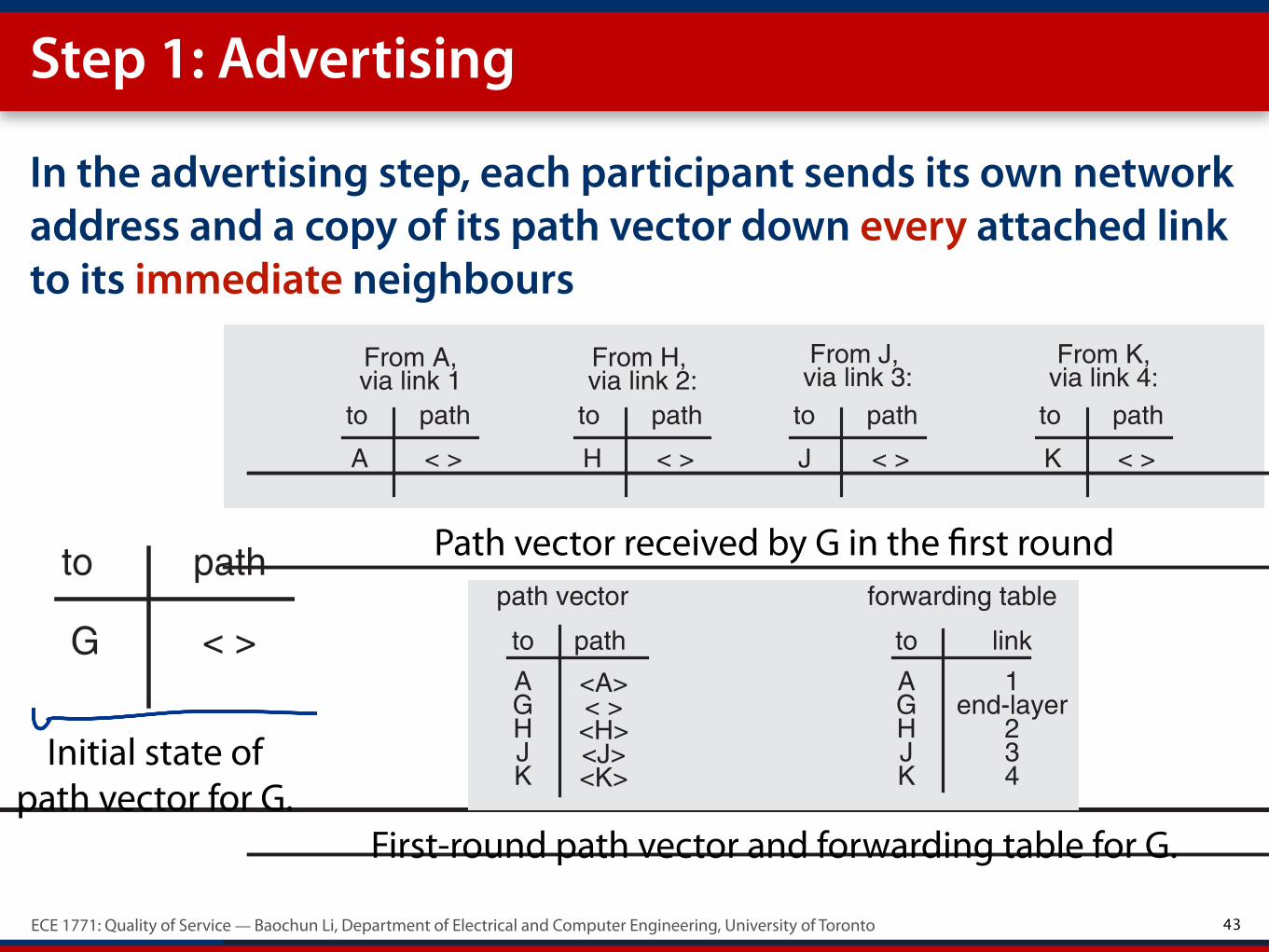
Step 1: Advertising
In the advertising step, each participant sends its own network address and a copy of its path vector down every attached link to its immediate neighbours
43
Saltzer & Kaashoek Ch. 7, p. 51 June 25, 2009 8:22 am
7.4 The Network Layer 7–51
so the packet departs from A by way of link 1, going to router G for its next stop.However, the forwarding table at G must be considerably more complicated. It mightcontain, for example, the following values:
This is not the only possible forwarding table for G. Since there are several possiblepaths to most destinations, there are several possible values for some of the table entries.In addition, it is essential that the forwarding tables in the other routers be coordinatedwith this forwarding table. If they are not, when router G sends a packet destined for Eto router K, router K might send it back to G, and the packet could loop forever.
The interesting question is how to construct a consistent, efficient set of forwardingtables. Many algorithms that sound promising have been proposed and tried; few workwell. One that works moderately well for small networks is known as path vectorexchange. Each participant maintains, in addition to its forwarding table, a path vector,each element of which is a complete path to some destination. Initially, the only path itknows about is the zero-length path to itself, but as the algorithm proceeds it graduallylearns about other paths. Eventually its path vector accumulates paths to every point inthe network. After each step of the algorithm it can construct a new forwarding tablefrom its new path vector, so the forwarding table gradually becomes more and morecomplete. The algorithm involves two steps that every participant repeats over and over,path advertising and path selection.
To illustrate the algorithm, suppose par-ticipant G starts with a path vector thatcontains just one item, an entry for itself, asin Figure 7.32. In the advertising step, eachparticipant sends its own network addressand a copy of its path vector down everyattached link to its immediate neighbors,specifying the network-layer protocolPATH_EXCHANGE. The routing algorithm of Gwould thus receive from its four neighborsthe four path vectors of Figure 7.33. This advertisement allows G to discover the names,which are in this case network addresses, of each of its neighbors.
destination link
A 1
CDEF
HJK
2
3
4
234
2
4
B
G end-layer
FIGURE 7.32
Initial state of path vector for G. < > is an empty path.
to path
G < >
Saltzer & Kaashoek Ch. 7, p. 52 June 25, 2009 8:22 am
CHAPTER 7 The Network as a System and as a System Component7–52
FIGURE 7.33
Path vectors received by G in the first round.
FIGURE 7.34
First-round path vector and forwarding table for G.
FIGURE 7.35
Path vectors received by G in the second round.
FIGURE 7.36
Second-round path vector and forwarding table for G.
From A, From H, From J, From K,
to path
A < >
to path
H < >
to path
J < >
to path
K < >
via link 1 via link 2: via link 3: via link 4:
to path
A <A>
to link
A 1GHJK
end-layer234
forwarding tablepath vector
G < >HJK
<H><J><K>
to path
A < >G <G>
to path
B <B>
G <G>HJK
< ><J><K>
to path
F <F>G <G>HJK
<H><J>< >
to path
D <D>
G <G>HJK
<H>< ><K>
From A, From H, From J, From K,via link 1 via link 2: via link 3: via link 4:
C <C>E <E>
E <E>
to path
A <A>
to link
A 1
GHJK
end-layer234
forwarding tablepath vector
G < >HJK
<H><J><K>
BCDE
BCDEF F
<H, B><H, C><J, D><J, E><K, F>
22334
Path vector received by G in the first round
First-round path vector and forwarding table for G.
Initial state of path vector for G.

ECE 1771: Quality of Service — Baochun Li, Department of Electrical and Computer Engineering, University of Toronto
Step 2. Path Selection
44

ECE 1771: Quality of Service — Baochun Li, Department of Electrical and Computer Engineering, University of Toronto
Step 2. Path Selection
G now performs the path selection step by merging the information received from its neighbours with that already in its own previous path vector
44

ECE 1771: Quality of Service — Baochun Li, Department of Electrical and Computer Engineering, University of Toronto
Step 2. Path Selection
G now performs the path selection step by merging the information received from its neighbours with that already in its own previous path vector
To do this merge, G takes each received path, prepends the network address of the neighbour that supplied it, and then decides whether or not to use this path in its own path vector
For previously unknown destinations, the answer is yes
For previously known destinations, G compares the paths that its neighbours have provided with the path it already had in its table, to see if the neighbour has a better path (e.g., a smaller number of hops to the destination)
44
ECE 1771: Quality of Service — Baochun Li, Department of Electrical and Computer Engineering, University of Toronto
Step 2. Path Selection
G now performs the path selection step by merging the information received from its neighbours with that already in its own previous path vector
To do this merge, G takes each received path, prepends the network address of the neighbour that supplied it, and then decides whether or not to use this path in its own path vector
For previously unknown destinations, the answer is yes
For previously known destinations, G compares the paths that its neighbours have provided with the path it already had in its table, to see if the neighbour has a better path (e.g., a smaller number of hops to the destination)
Each router discards any paths that a neighbour stops advertising — to discard links that go down
44

ECE 1771: Quality of Service — Baochun Li, Department of Electrical and Computer Engineering, University of Toronto
Loops are still possible in forwarding tables
45

ECE 1771: Quality of Service — Baochun Li, Department of Electrical and Computer Engineering, University of Toronto
Loops are still possible in forwarding tables
Temporary loops are still possible
If a link has gone down, some packets may loop for a while until everyone agrees on the new forwarding tables!
Solution: hop limit
Add a field to the network-layer header containing a hop limit counter
Decrements the hop limit counter by each router
If a router finds it to be zero, it discards the packet
45

ECE 1771: Quality of Service — Baochun Li, Department of Electrical and Computer Engineering, University of Toronto
Introducing hierarchies
46

ECE 1771: Quality of Service — Baochun Li, Department of Electrical and Computer Engineering, University of Toronto
Introducing hierarchies
Two problems in our solutions so far —
Every attachment point must have a unique address — it is hard to maintain a complete and accurate list of addresses already assigned when the number of addresses is large
The path vector grows in size with the number of attachment points
Solution: introducing hierarchies
Network addresses should be designed to have a hierarchical structure
Both for decentralizing address assignments and for reducing the size of forwarding tables and path vectors
46

ECE 1771: Quality of Service — Baochun Li, Department of Electrical and Computer Engineering, University of Toronto
Hierarchical address assignment: benefits
47

ECE 1771: Quality of Service — Baochun Li, Department of Electrical and Computer Engineering, University of Toronto
Hierarchical address assignment: benefits
Assume that we have two hierarchies — a “region” and a “station”
We may assign to A the network address “11, 75”, where 11 is a region identifier and 75 is a station identifier
Key benefit — reduction of path vectors
If we can adopt a policy that regions must correspond to the set of network attachment points served by a group of closely-connected routers, we can use it to reduce the size of forwarding tables and path vectors
For example, when a router for region 11 gets ready to advertise its path vector to a router serving region 12, it can condense all paths for region 11 into a single path
47

ECE 1771: Quality of Service — Baochun Li, Department of Electrical and Computer Engineering, University of Toronto
Hierarchical address assignment: benefits
48

ECE 1771: Quality of Service — Baochun Li, Department of Electrical and Computer Engineering, University of Toronto
Hierarchical address assignment: benefits
Now the problem of assigning unique addresses in a large network is also solved
48

ECE 1771: Quality of Service — Baochun Li, Department of Electrical and Computer Engineering, University of Toronto
Hierarchical address assignment: benefits
Now the problem of assigning unique addresses in a large network is also solved
The “station” part of a network address needs to be unique only within its region
A central authority assigns region identifiers
Local authorities assign station identifiers within each region
48

ECE 1771: Quality of Service — Baochun Li, Department of Electrical and Computer Engineering, University of Toronto
Hierarchical address assignment: complexities
49

ECE 1771: Quality of Service — Baochun Li, Department of Electrical and Computer Engineering, University of Toronto
Hierarchical address assignment: complexities
The table lookup process is more complicated
49

ECE 1771: Quality of Service — Baochun Li, Department of Electrical and Computer Engineering, University of Toronto
Hierarchical address assignment: complexities
The table lookup process is more complicated
the forwarder needs to first extract the region component of the destination address, and look that up in its forwarding table
Either the forwarding table contains an entry showing a link over which to send the packet to that region
49
ECE 1771: Quality of Service — Baochun Li, Department of Electrical and Computer Engineering, University of Toronto
Hierarchical address assignment: complexities
The table lookup process is more complicated
the forwarder needs to first extract the region component of the destination address, and look that up in its forwarding table
Either the forwarding table contains an entry showing a link over which to send the packet to that region
Or the forwarding table contains an entry saying that this forwarder is already in the destination region — it is now necessary to extract the station identifier and look that up in a different part of the forwarding table
49

ECE 1771: Quality of Service — Baochun Li, Department of Electrical and Computer Engineering, University of Toronto
Hierarchical address assignment: complexities
The table lookup process is more complicated
the forwarder needs to first extract the region component of the destination address, and look that up in its forwarding table
Either the forwarding table contains an entry showing a link over which to send the packet to that region
Or the forwarding table contains an entry saying that this forwarder is already in the destination region — it is now necessary to extract the station identifier and look that up in a different part of the forwarding table
The addresses are becoming geographically dependent
Paths may no longer be the shortest possible
49

ECE 1771: Quality of Service — Baochun Li, Department of Electrical and Computer Engineering, University of Toronto
Reading: Keshav 6.1 — 6.5, Salzer 7.3 — 7.4