Embed Size (px)
Citation preview
EPICS Class – Process Database • Most slides here are taken from:
– “EPICS Database Principles” by Andrew Johnson
• Some slides modified by me • After lecture, study:
– “EPICS Database Practice” by Andrew Johnson
EPICS Class – Process Database 1 4/23/2012
EPICS Class – Process Database Outline • What is a process database and why use it? • Records • Fields in Records (PVs) • Record Processing • Input and Output Records • Record Linking • Device Support and Soft Records • Synchronous and Asynchronous I/O • Common Fields/Functions in Most Records
EPICS Class – Process Database 2 4/23/2012
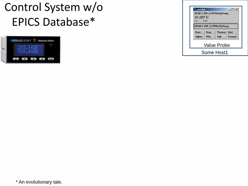
Control System w/o EPICS Database*
Value Probe Some Host1
* An evolutionary tale.
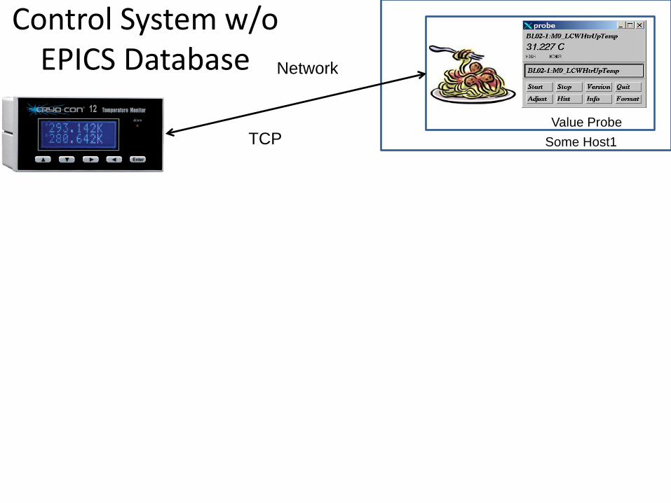
Control System w/o EPICS Database
Value Probe Some Host1
Network
TCP
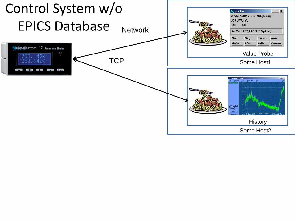
Control System w/o EPICS Database
Value Probe Some Host1
Network
TCP
History Some Host2
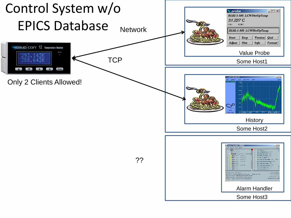
Control System w/o EPICS Database
Value Probe Some Host1
Network
TCP
History Some Host2
Alarm Handler Some Host3
Only 2 Clients Allowed!
??
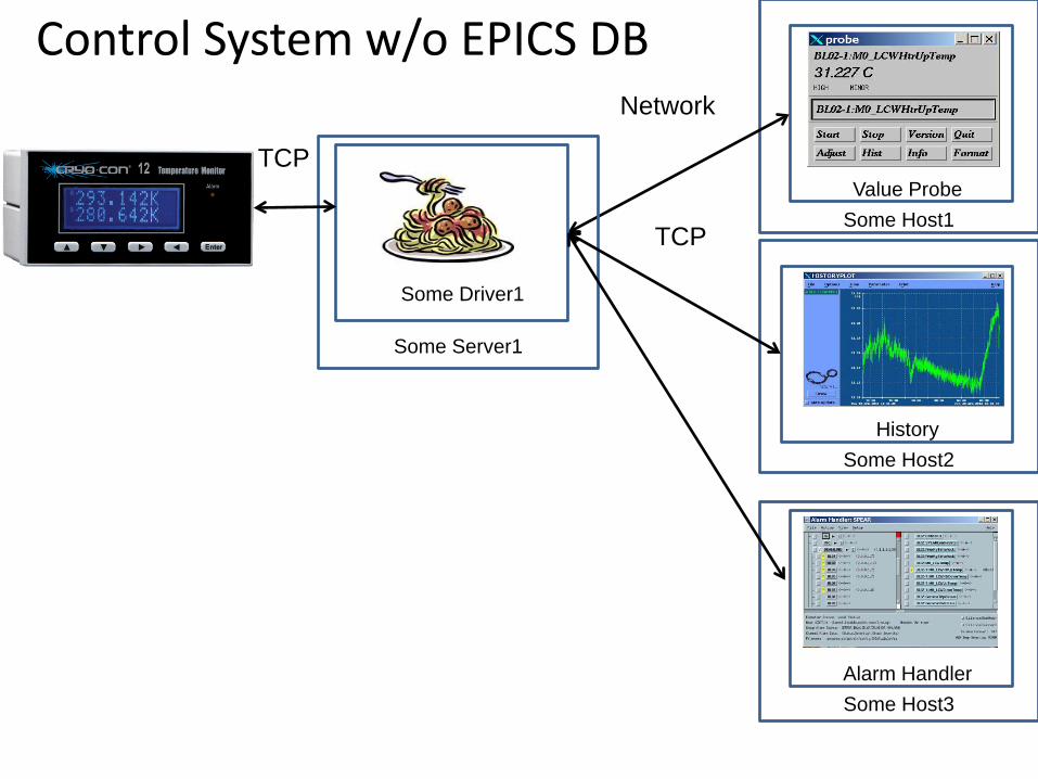
Control System w/o EPICS DB
Value Probe Some Host1
Network
TCP
History Some Host2
Alarm Handler Some Host3
Some Server1
Some Driver1
TCP
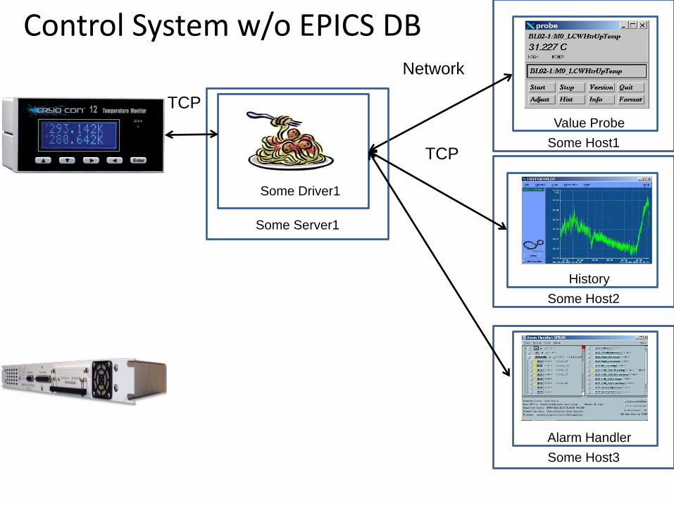
Control System w/o EPICS DB
Value Probe Some Host1
Network
TCP
History Some Host2
Alarm Handler Some Host3
Some Server1
Some Driver1
TCP
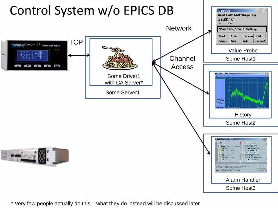
Control System w/o EPICS DB
Value Probe Some Host1
Network
Channel Access
History Some Host2
Alarm Handler Some Host3
Some Server1
Some Driver1 with CA Server*
TCP
* Very few people actually do this – what they do instead will be discussed later .
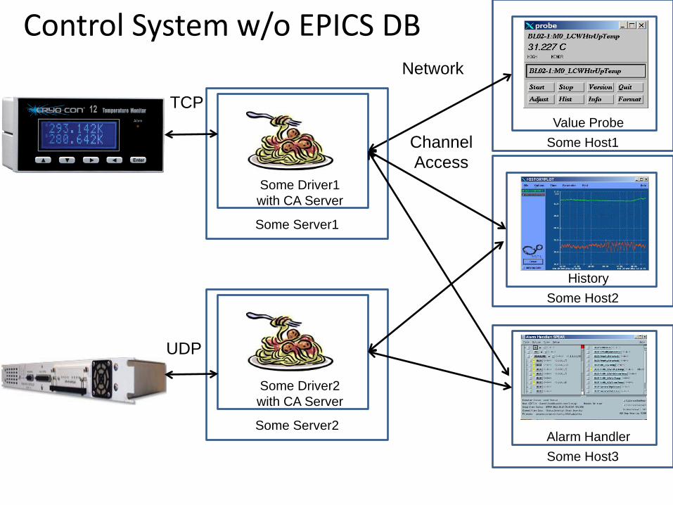
Control System w/o EPICS DB
Value Probe Some Host1
Network
Channel Access
History Some Host2
Alarm Handler Some Host3
Some Server1
Some Driver1 with CA Server
TCP
Some Server2
Some Driver2 with CA Server
UDP
Control System w/o EPICS DB
Value Probe Some Host1
Network
Channel Access
History Some Host2
Alarm Handler Some Host3
Some Server1
CA Server1
TCP
UDP
CC Drv
Some Server2
CA Server2 PSC Drv
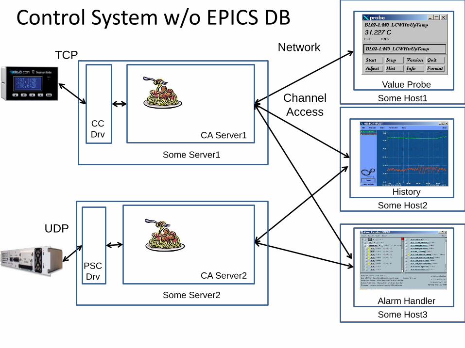
Control System w/o EPICS DB
Value Probe Some Host1
Network
Channel Access
History Some Host2
Alarm Handler Some Host3
Some Server1
TCP
UDP
CC Drv
Some Server2
PSC Drv
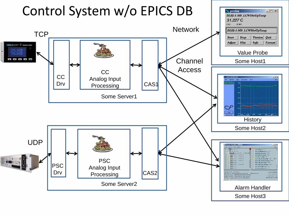
CAS1
CAS2
CC Analog Input Processing
PSC Analog Input Processing
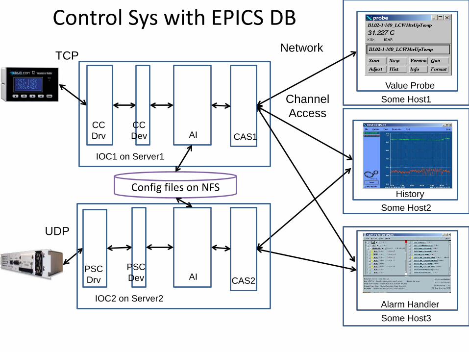
Control Sys with EPICS DB
Value Probe Some Host1
Network
Channel Access
History Some Host2
Alarm Handler Some Host3
IOC1 on Server1
TCP
UDP
CC Drv
IOC2 on Server2
PSC Drv
CAS1
CAS2
AI
AI
CC Dev
PSC Dev
Config files on NFS
14
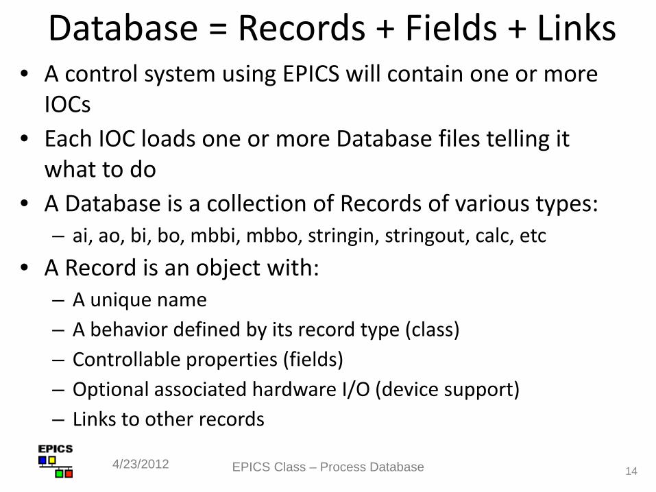
Database = Records + Fields + Links • A control system using EPICS will contain one or more
IOCs • Each IOC loads one or more Database files telling it
what to do • A Database is a collection of Records of various types:
– ai, ao, bi, bo, mbbi, mbbo, stringin, stringout, calc, etc • A Record is an object with:
– A unique name – A behavior defined by its record type (class) – Controllable properties (fields) – Optional associated hardware I/O (device support) – Links to other records
4/23/2012 EPICS Class – Process Database
15
Record Activity • Records are active — they can do things:
– Get data from other records or from hardware – Perform calculations – Check values are in range & raise alarms – Put data to other records or to hardware – Activate or disable other records – Wait for hardware signals (interrupts)
• What a record does depends upon its record type and the settings of its fields
• No action occurs unless a record is processed
4/23/2012 EPICS Class – Process Database
How is a Record type implemented? • A ‘C’ structure with a data member for each record field
– All records start with a standard set of fields (dbCommon) that the system needs, including pointers to record type information (base/include/dbCommon.h)
– Additional fields are added depending on record type – The configuration of the ‘C’ structure is provided by a database
definition ASCII file (<name>Record.dbd) which is unique to the record type <name>
– Standard records in base/src/rec/<name>Record.dbd • Code (ie, ‘C’) which implements the record behavior
– Standard records in base/src/rec/<name>Record.c • New record types can be added to an application as
needed – recommend only if absolutely necessary EPICS Class – Process Database 4/23/2012 16
17
How are individual Records defined? • A database configuration ASCII file (.db or .template)
providing record field values: – Record name – The record’s type – Values for each design field – Can use macros for fields so that same configuration file is
used for many records • IOC application build (make) can create and/or install
.db files • Record instantiation (ie, memory allocation on IOC)
done before iocInit by dbLoadRecords in the IOC startup file.
EPICS Class – Process Database 4/23/2012
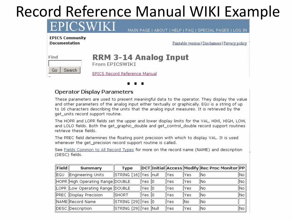
Record Reference Manual WIKI Example
…
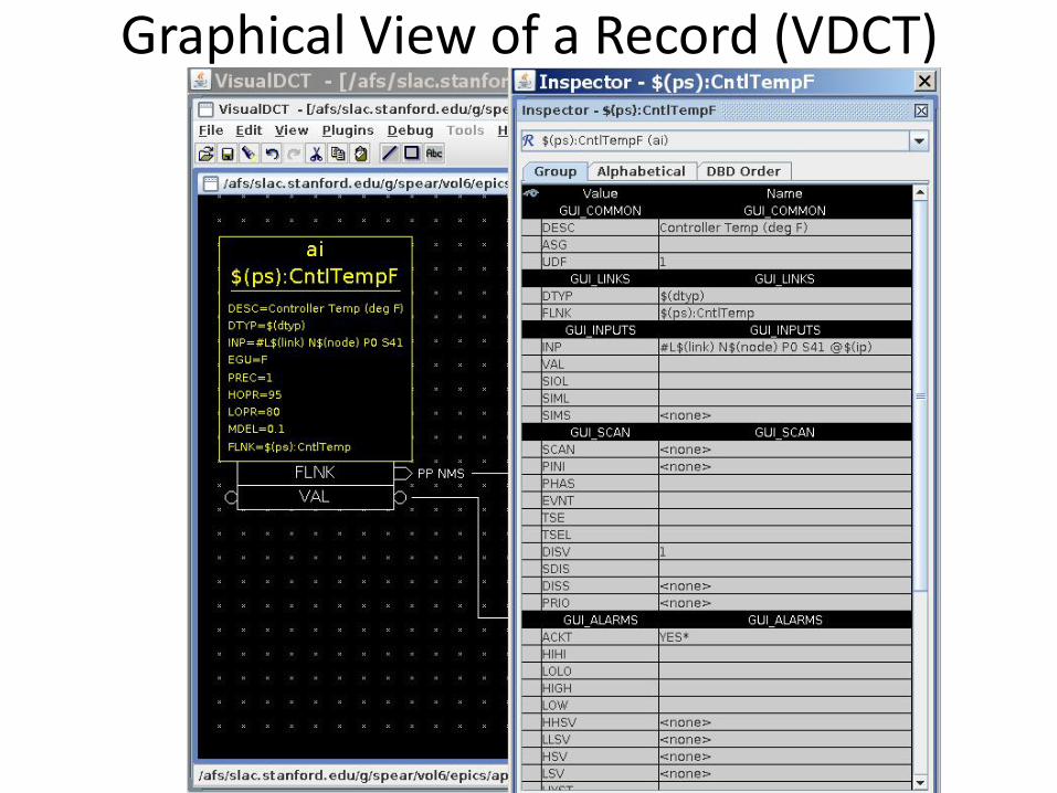
Graphical View of a Record (VDCT)
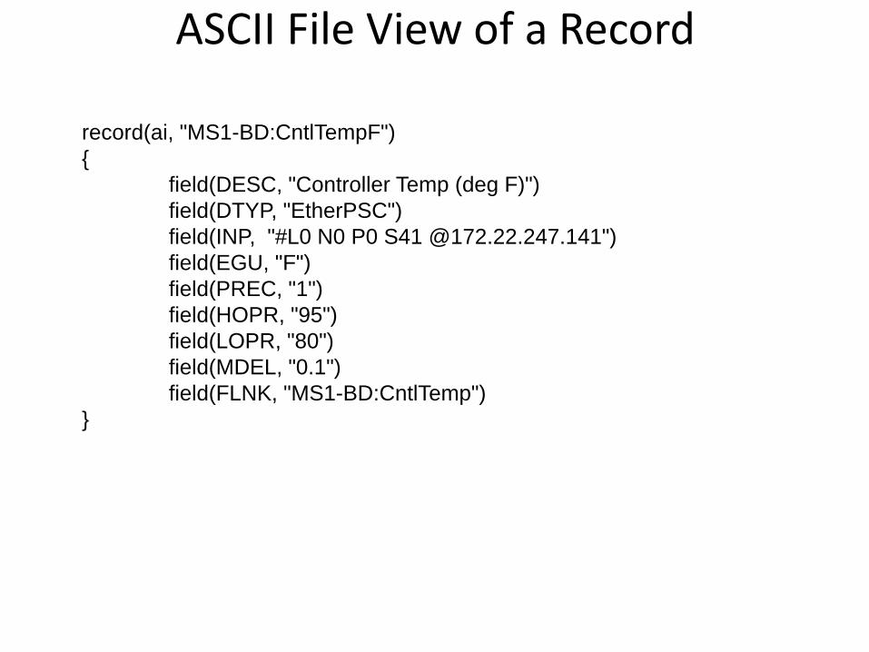
ASCII File View of a Record
record(ai, "MS1-BD:CntlTempF") { field(DESC, "Controller Temp (deg F)") field(DTYP, "EtherPSC") field(INP, "#L0 N0 P0 S41 @172.22.247.141") field(EGU, "F") field(PREC, "1") field(HOPR, "95") field(LOPR, "80") field(MDEL, "0.1") field(FLNK, "MS1-BD:CntlTemp") }
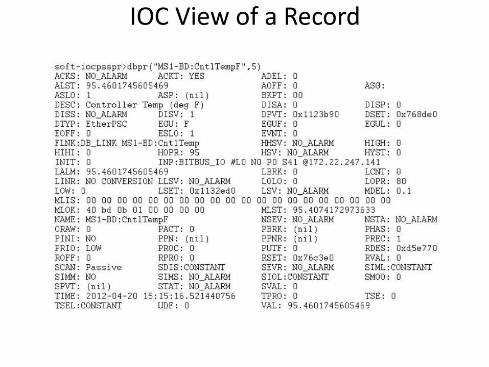
IOC View of a Record
Fields – Process Variable (PV)
• PV = <record_name>.<field> • Example: MS1-BD:CntrlTempF.DESC • If .<field> is not provided, .VAL is assumed.
EPICS Class – Process Database 22 4/23/2012
Fields are for... • Defining
– What causes a record to process – Where to get/put data from/to – How to turn raw I/O data into a numeric engineering value – Limits indicating when to report an alarm – When to notify value changes to a client monitoring the record – A Processing algorithm – Anything else which needs to be set for each record of a given type
• Holding run-time data – Input or output values – Alarm status, severity and acknowledgments – Processing timestamp – Other data for internal use
EPICS Class – Process Database 23 4/23/2012
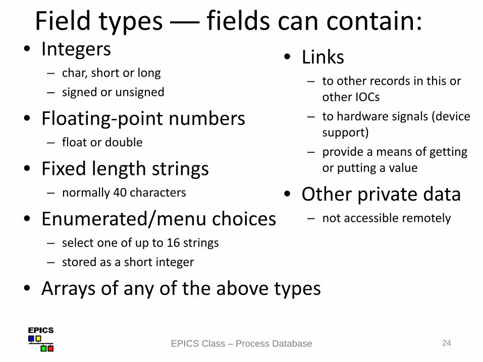
Field types — fields can contain: • Integers
– char, short or long – signed or unsigned
• Floating-point numbers – float or double
• Fixed length strings – normally 40 characters
• Enumerated/menu choices – select one of up to 16 strings – stored as a short integer
• Arrays of any of the above types
• Links – to other records in this or
other IOCs – to hardware signals (device
support) – provide a means of getting
or putting a value
• Other private data – not accessible remotely
EPICS Class – Process Database 24
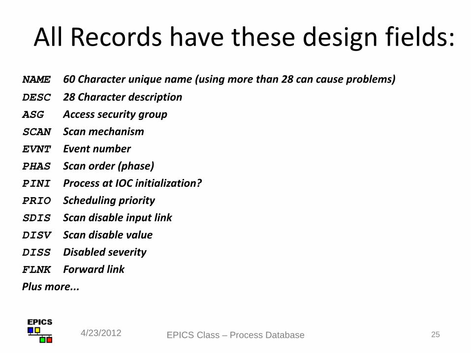
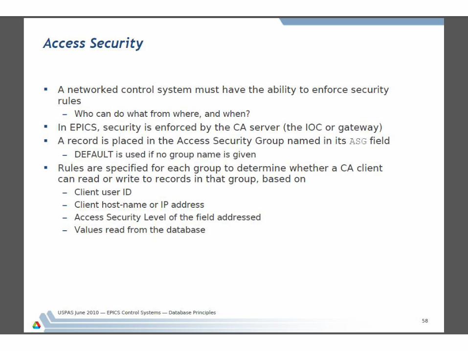
All Records have these design fields: NAME 60 Character unique name (using more than 28 can cause problems) DESC 28 Character description ASG Access security group SCAN Scan mechanism EVNT Event number PHAS Scan order (phase) PINI Process at IOC initialization? PRIO Scheduling priority SDIS Scan disable input link DISV Scan disable value DISS Disabled severity FLNK Forward link Plus more...
EPICS Class – Process Database 25 4/23/2012
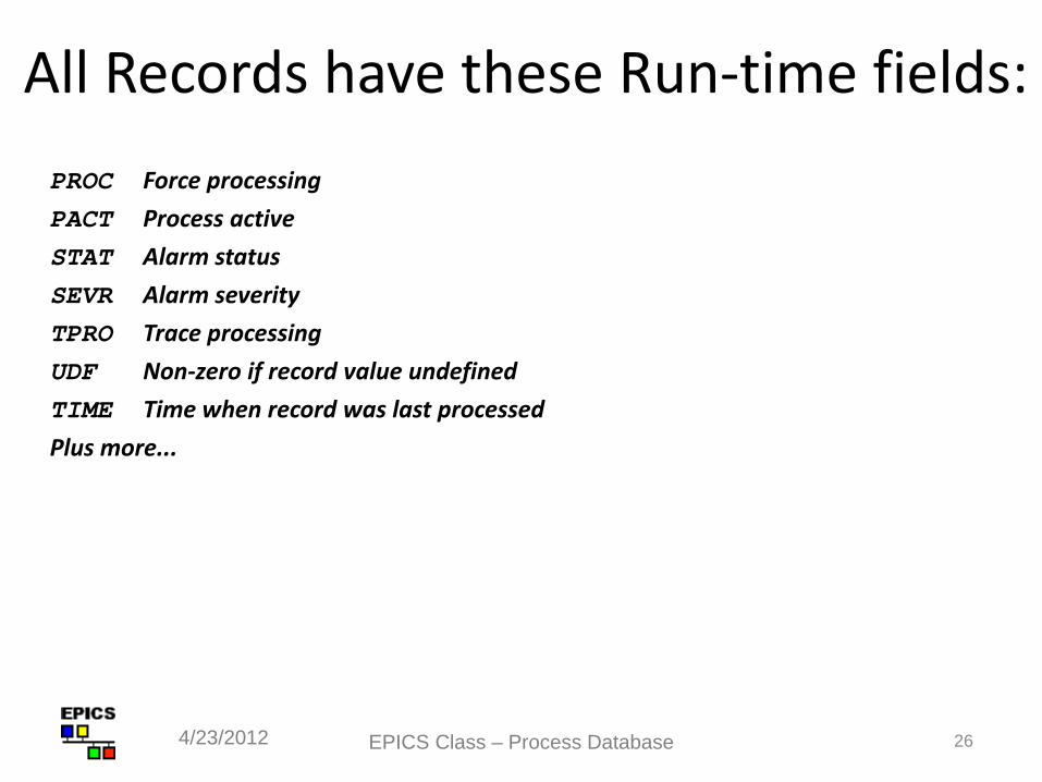
All Records have these Run-time fields: PROC Force processing PACT Process active STAT Alarm status SEVR Alarm severity TPRO Trace processing UDF Non-zero if record value undefined TIME Time when record was last processed Plus more...
EPICS Class – Process Database 26 4/23/2012
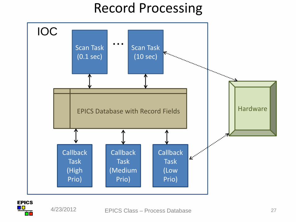
Record Processing
EPICS Class – Process Database 27 4/23/2012
Scan Task (0.1 sec)
Scan Task (10 sec)
...
Callback Task (High Prio)
Callback Task
(Medium Prio)
Callback Task (Low Prio)
EPICS Database with Record Fields
IOC
Hardware
28
How are records given CPU time?
Several IOC tasks are used: • callback (3 priorities) — I/O Interrupt and Event • scanPeriod (periods are configurable) — Periodic
– A separate task is used for each scan period – Faster scan rates are given a higher task priority (if supported by the
IOC’s Operating System)
• scanOnce – special purpose • sequence and other run-time database tasks • Channel Access tasks use lower priority than record
processing – If a CPU spends all its time doing I/O and record processing, you
may be unable to control or monitor the IOC via the network
4/23/2012 EPICS Class – Process Database
29
Record Scanning • SCAN field is a menu choice from
– Periodic — 0.1 seconds .. 10 seconds – I/O Interrupt (if device supports this) – Soft and Hard event — EVNT field – Passive (default)
• The number in the PHAS field allows processing order to be set within a scan – Records with PHAS=0 are processed first – Then those with PHAS=1 , PHAS=2 etc.
• Records with PINI=YES are processed once at startup • PRIO field selects Low/Medium/High priority for event and I/O Interrupts
(selects which callback task will process the record) • A record is also processed whenever any value is written to its PROC field
4/23/2012 EPICS Class – Process Database
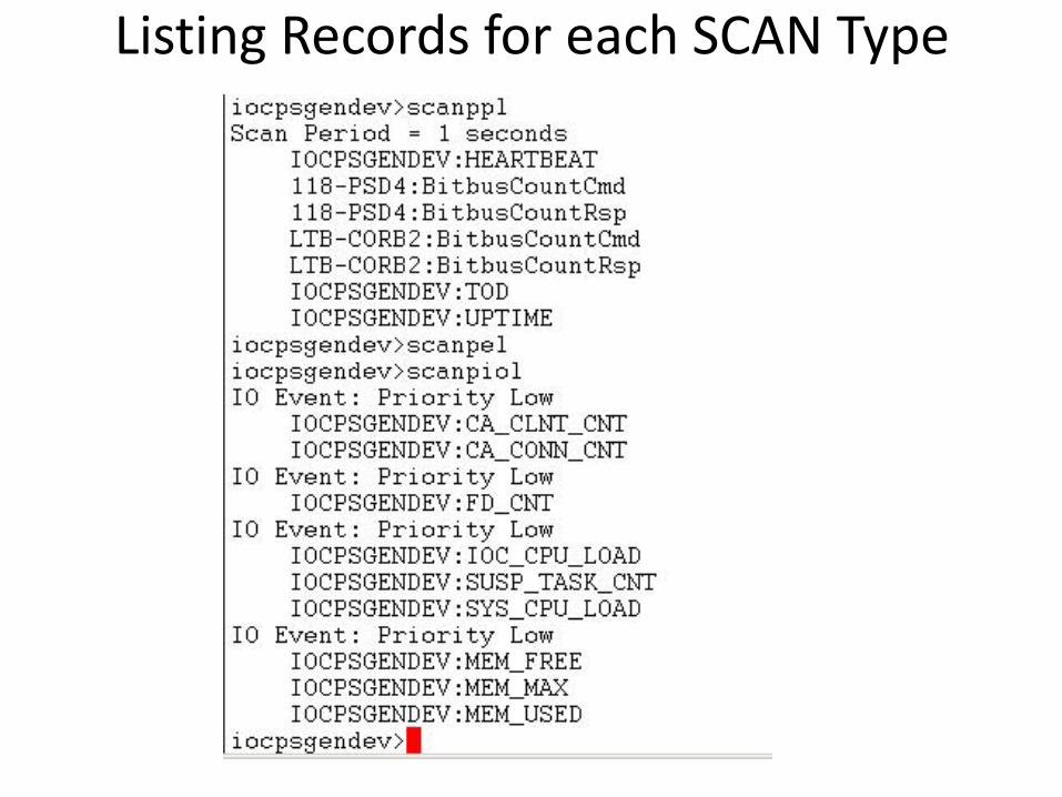
Listing Records for each SCAN Type
Input and Output Records
EPICS Class – Process Database 31 4/23/2012
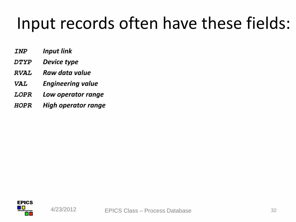
Input records often have these fields: INP Input link DTYP Device type RVAL Raw data value VAL Engineering value LOPR Low operator range HOPR High operator range
EPICS Class – Process Database 32 4/23/2012
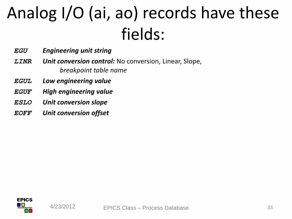
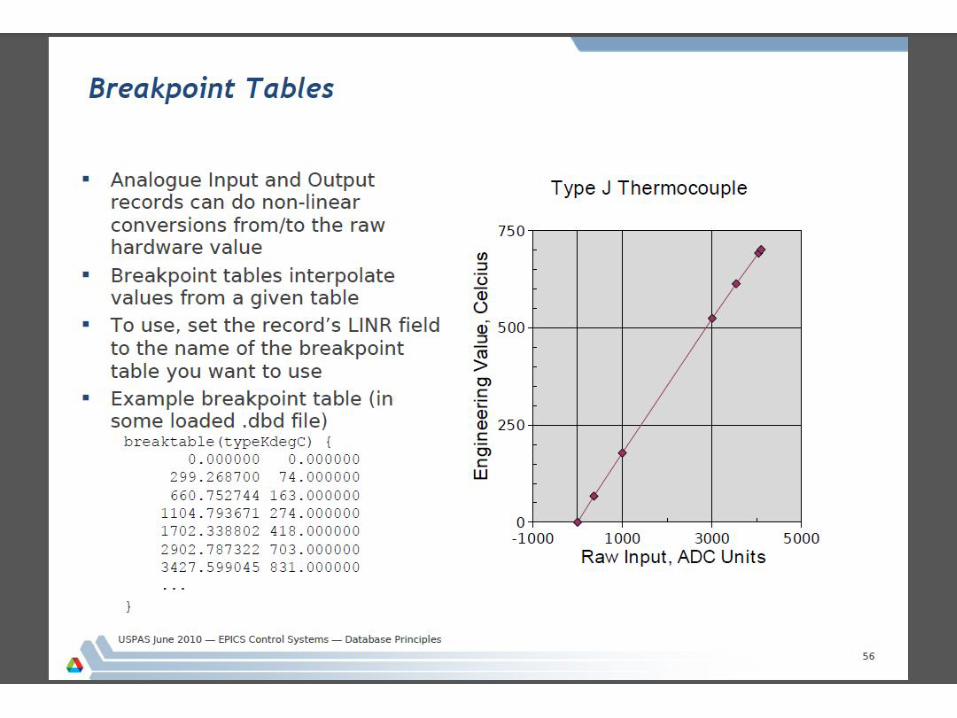
Analog I/O (ai, ao) records have these fields:
EGU Engineering unit string LINR Unit conversion control: No conversion, Linear, Slope,
breakpoint table name EGUL Low engineering value EGUF High engineering value ESLO Unit conversion slope EOFF Unit conversion offset
EPICS Class – Process Database 33 4/23/2012
34
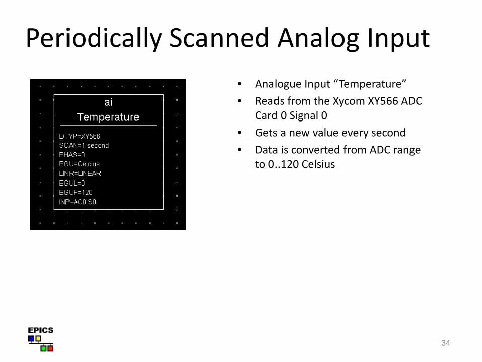
Periodically Scanned Analog Input • Analogue Input “Temperature” • Reads from the Xycom XY566 ADC
Card 0 Signal 0 • Gets a new value every second • Data is converted from ADC range
to 0..120 Celsius
35
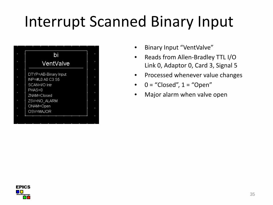
Interrupt Scanned Binary Input • Binary Input “VentValve” • Reads from Allen-Bradley TTL I/O
Link 0, Adaptor 0, Card 3, Signal 5 • Processed whenever value changes • 0 = “Closed”, 1 = “Open” • Major alarm when valve open
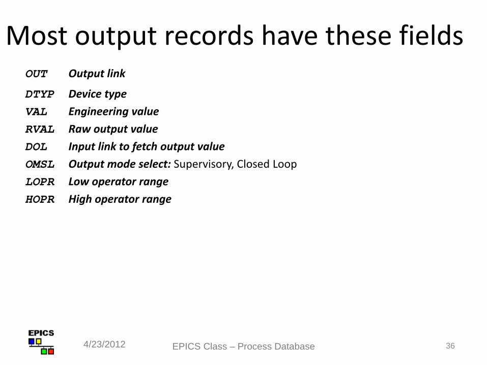
Most output records have these fields OUT Output link
DTYP Device type VAL Engineering value RVAL Raw output value DOL Input link to fetch output value OMSL Output mode select: Supervisory, Closed Loop LOPR Low operator range HOPR High operator range
EPICS Class – Process Database 36 4/23/2012
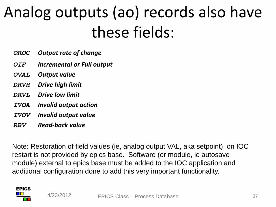
Analog outputs (ao) records also have these fields:
OROC Output rate of change
OIF Incremental or Full output OVAL Output value DRVH Drive high limit DRVL Drive low limit IVOA Invalid output action IVOV Invalid output value RBV Read-back value
EPICS Class – Process Database 37 4/23/2012
Note: Restoration of field values (ie, analog output VAL, aka setpoint) on IOC restart is not provided by epics base. Software (or module, ie autosave module) external to epics base must be added to the IOC application and additional configuration done to add this very important functionality.
38
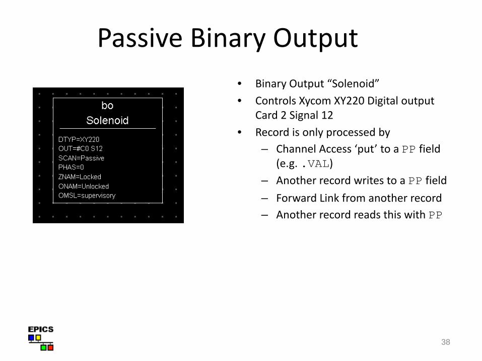
Passive Binary Output • Binary Output “Solenoid” • Controls Xycom XY220 Digital output
Card 2 Signal 12 • Record is only processed by
– Channel Access ‘put’ to a PP field (e.g. .VAL)
– Another record writes to a PP field – Forward Link from another record – Another record reads this with PP
Links
A link is a type of field, and is one of • Input link (ie, input record INP field, output record DOL field)
Fetches data • Output link (ie, output record OUT field)
Writes data
• Forward link (ie, any record FLNK field) Points to the record to be processed once this record finishes processing
EPICS Class – Process Database 39 4/23/2012
Input and Output links may be... • Constant numeric value, e.g.:
0 3.1415926536 -1.6e-19
• “Hardware” link A hardware (or external) I/O signal selector, the format of
which depends on the device support layer
• Process Variable link — the name of a record, which at run-time is resolved into – Database link - Named record is in this IOC – Channel Access link - Named record not found in this IOC
EPICS Class – Process Database 40 4/23/2012
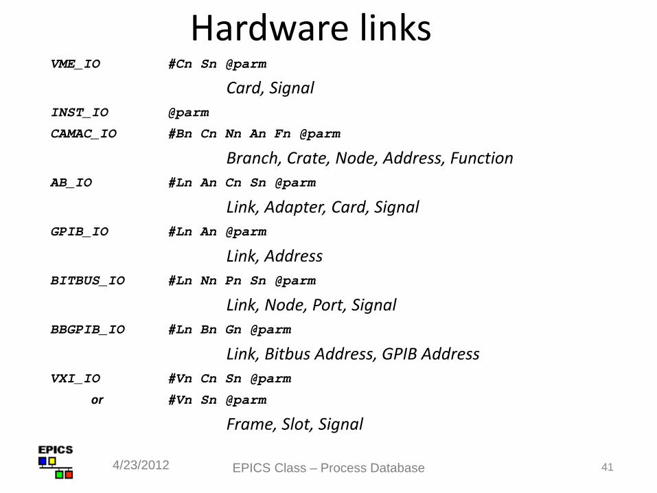
Hardware links VME_IO #Cn Sn @parm
Card, Signal INST_IO @parm
CAMAC_IO #Bn Cn Nn An Fn @parm
Branch, Crate, Node, Address, Function AB_IO #Ln An Cn Sn @parm
Link, Adapter, Card, Signal GPIB_IO #Ln An @parm
Link, Address BITBUS_IO #Ln Nn Pn Sn @parm
Link, Node, Port, Signal BBGPIB_IO #Ln Bn Gn @parm
Link, Bitbus Address, GPIB Address VXI_IO #Vn Cn Sn @parm
or #Vn Sn @parm
Frame, Slot, Signal
EPICS Class – Process Database 41 4/23/2012
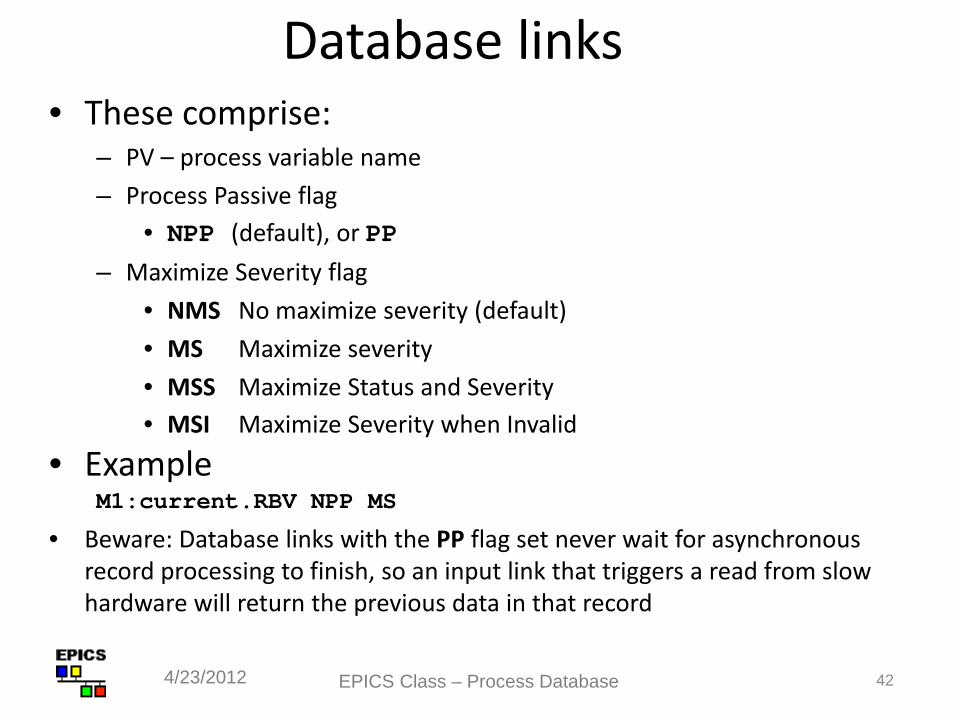
Database links • These comprise:
– PV – process variable name – Process Passive flag
• NPP (default), or PP – Maximize Severity flag
• NMS No maximize severity (default) • MS Maximize severity • MSS Maximize Status and Severity • MSI Maximize Severity when Invalid
• Example M1:current.RBV NPP MS
• Beware: Database links with the PP flag set never wait for asynchronous record processing to finish, so an input link that triggers a read from slow hardware will return the previous data in that record
EPICS Class – Process Database 42 4/23/2012
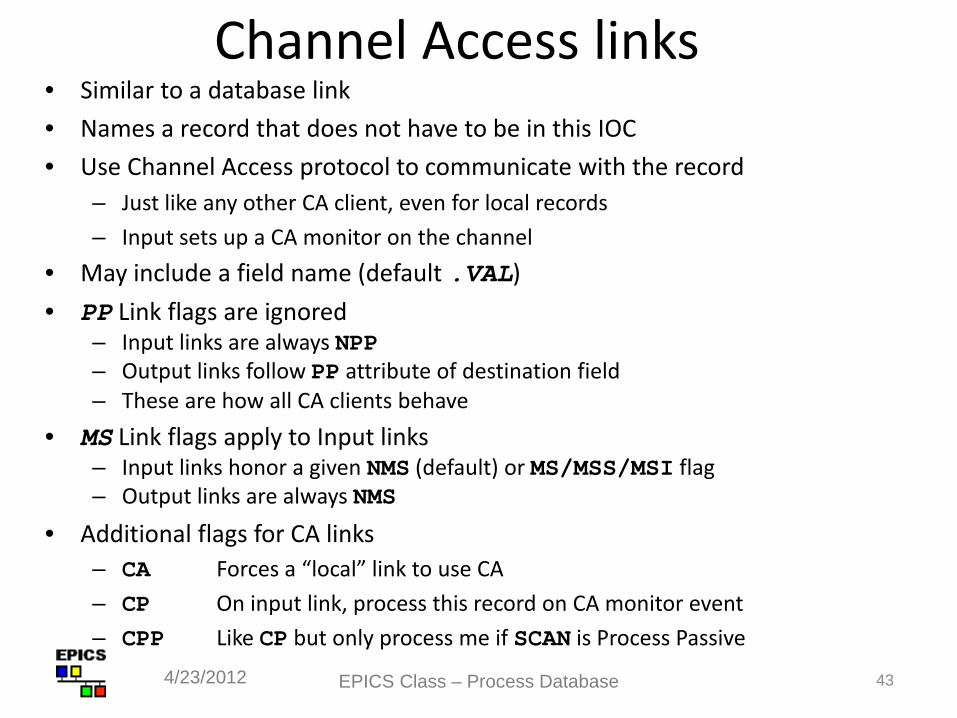
Channel Access links • Similar to a database link • Names a record that does not have to be in this IOC • Use Channel Access protocol to communicate with the record
– Just like any other CA client, even for local records – Input sets up a CA monitor on the channel
• May include a field name (default .VAL) • PP Link flags are ignored
– Input links are always NPP – Output links follow PP attribute of destination field – These are how all CA clients behave
• MS Link flags apply to Input links – Input links honor a given NMS (default) or MS/MSS/MSI flag – Output links are always NMS
• Additional flags for CA links – CA Forces a “local” link to use CA – CP On input link, process this record on CA monitor event – CPP Like CP but only process me if SCAN is Process Passive
EPICS Class – Process Database 43 4/23/2012
44
Forward links • Usually a Database link, referring to a record in same IOC • No flags (PP, MS etc.), although VDCT includes them
erroneously • Destination record is only processed if its SCAN field is Passive
• Does not pass a value, just causes subsequent processing • Forward linking to another IOC via Channel Access is
possible, but the link must explicitly name the PROC field of the remote record – In this case, the remote record does not need to have SCAN set to Passive
Chapter 5 of the IOC Application Developer’s Guide covers record links and scanning in detail, and is worth reading.
Good idea to just read the whole manual…
EPICS Class – Process Database 45 4/23/2012
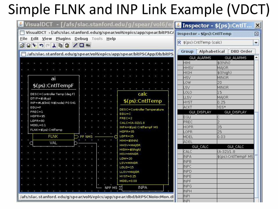
Simple FLNK and INP Link Example (VDCT)
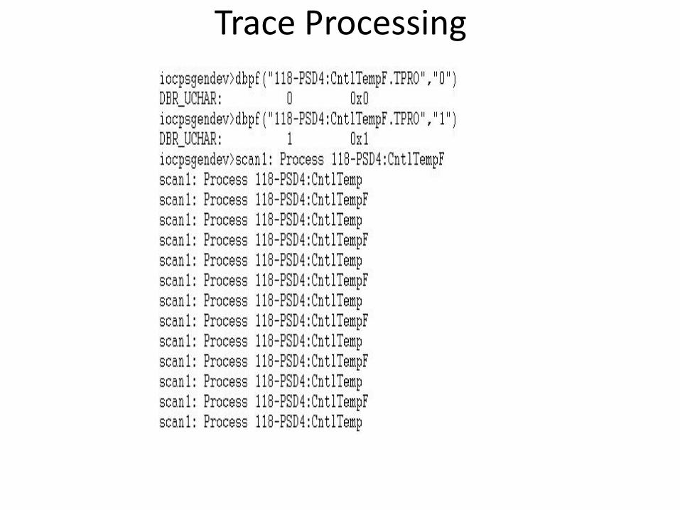
Trace Processing
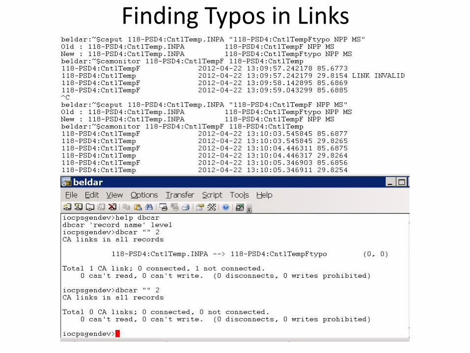
Finding Typos in Links
49
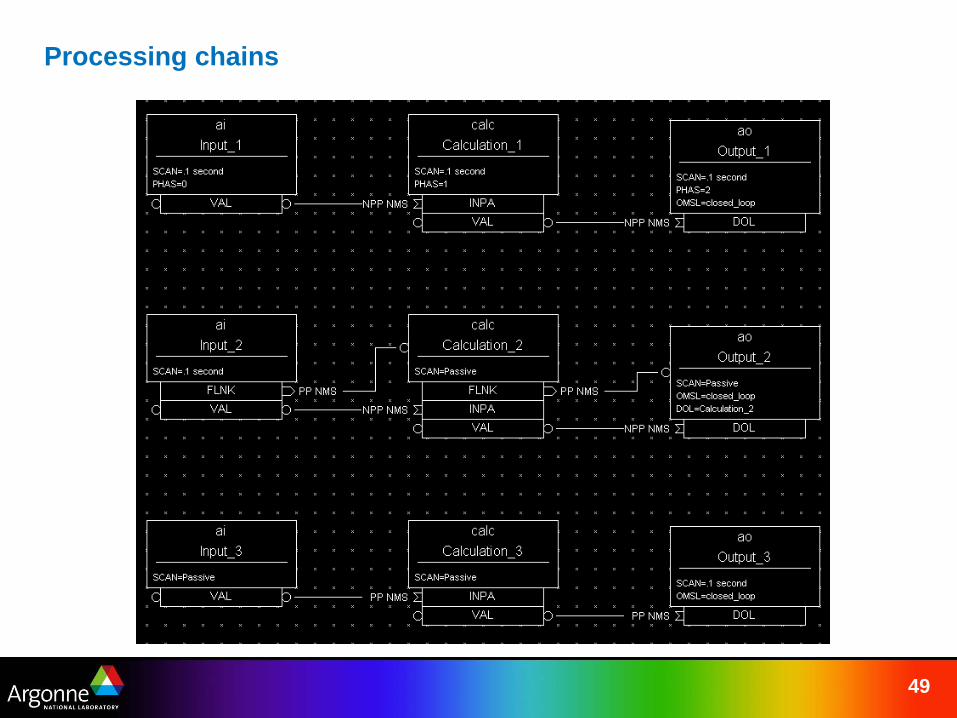
Processing chains
50
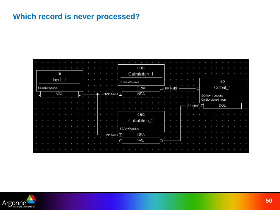
Which record is never processed?
51
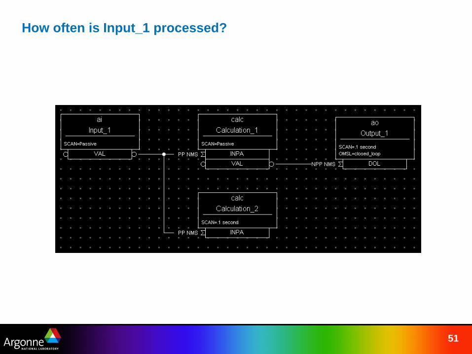
How often is Input_1 processed?
52
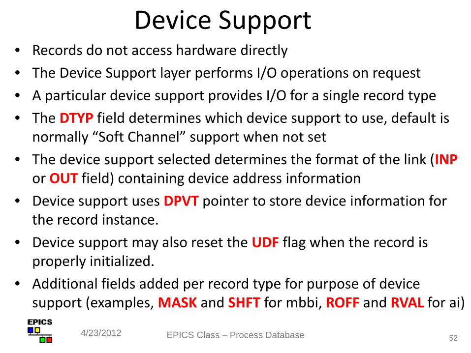
Device Support • Records do not access hardware directly • The Device Support layer performs I/O operations on request • A particular device support provides I/O for a single record type • The DTYP field determines which device support to use, default is
normally “Soft Channel” support when not set • The device support selected determines the format of the link (INP
or OUT field) containing device address information • Device support uses DPVT pointer to store device information for
the record instance. • Device support may also reset the UDF flag when the record is
properly initialized. • Additional fields added per record type for purpose of device
support (examples, MASK and SHFT for mbbi, ROFF and RVAL for ai)
4/23/2012 EPICS Class – Process Database
Device Support, cont • Adding new device support does not require any changes or
recompilation of the record type code • Device support often calls other software to do work for it
(Driver Support or other libraries) • Device support most often thin layer – record and driver
support do most of the legwork
EPICS Class – Process Database 53 4/23/2012
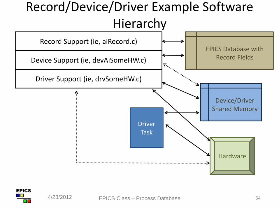
Record/Device/Driver Example Software Hierarchy
EPICS Class – Process Database 54 4/23/2012
Record Support (ie, aiRecord.c) EPICS Database with
Record Fields Device Support (ie, devAiSomeHW.c)
Device/Driver Shared Memory
Driver Support (ie, drvSomeHW.c)
Driver Task
Hardware
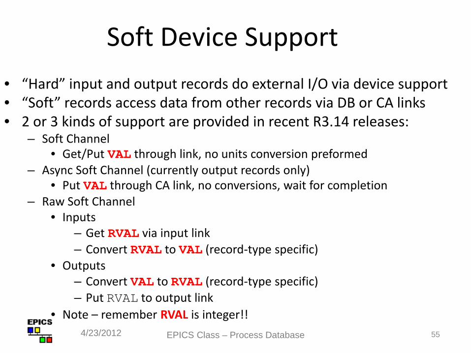
Soft Device Support • “Hard” input and output records do external I/O via device support • “Soft” records access data from other records via DB or CA links • 2 or 3 kinds of support are provided in recent R3.14 releases:
– Soft Channel • Get/Put VAL through link, no units conversion preformed
– Async Soft Channel (currently output records only) • Put VAL through CA link, no conversions, wait for completion
– Raw Soft Channel • Inputs
– Get RVAL via input link – Convert RVAL to VAL (record-type specific)
• Outputs – Convert VAL to RVAL (record-type specific) – Put RVAL to output link
• Note – remember RVAL is integer!! EPICS Class – Process Database 55 4/23/2012
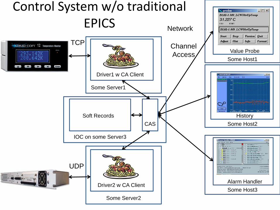
Control System w/o traditional EPICS
Value Probe Some Host1
Network
Channel Access
History Some Host2
Alarm Handler Some Host3
Some Server1
Driver1 w CA Client
TCP
Some Server2
Driver2 w CA Client
UDP
IOC on some Server3
CAS Soft Records
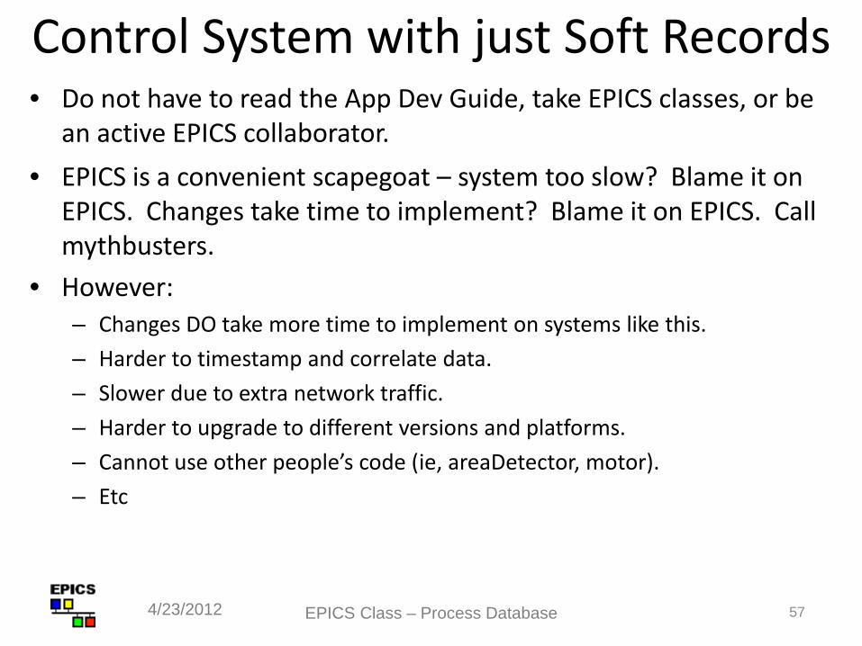
Control System with just Soft Records • Do not have to read the App Dev Guide, take EPICS classes, or be
an active EPICS collaborator. • EPICS is a convenient scapegoat – system too slow? Blame it on
EPICS. Changes take time to implement? Blame it on EPICS. Call mythbusters.
• However: – Changes DO take more time to implement on systems like this. – Harder to timestamp and correlate data. – Slower due to extra network traffic. – Harder to upgrade to different versions and platforms. – Cannot use other people’s code (ie, areaDetector, motor). – Etc
EPICS Class – Process Database 57 4/23/2012
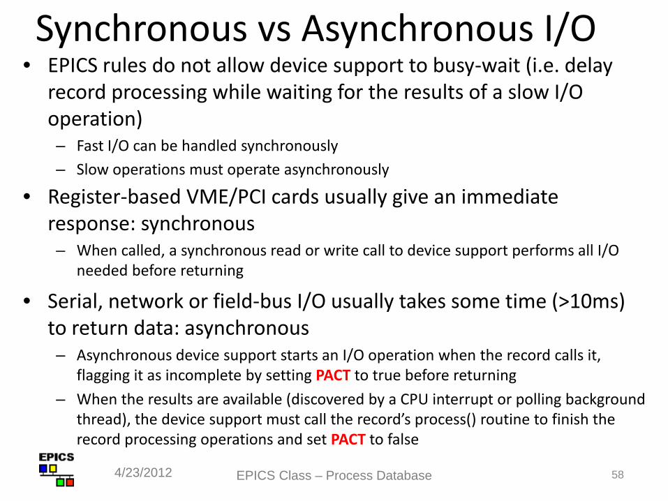
Synchronous vs Asynchronous I/O • EPICS rules do not allow device support to busy-wait (i.e. delay
record processing while waiting for the results of a slow I/O operation) – Fast I/O can be handled synchronously – Slow operations must operate asynchronously
• Register-based VME/PCI cards usually give an immediate response: synchronous – When called, a synchronous read or write call to device support performs all I/O
needed before returning
• Serial, network or field-bus I/O usually takes some time (>10ms) to return data: asynchronous – Asynchronous device support starts an I/O operation when the record calls it,
flagging it as incomplete by setting PACT to true before returning – When the results are available (discovered by a CPU interrupt or polling background
thread), the device support must call the record’s process() routine to finish the record processing operations and set PACT to false
EPICS Class – Process Database 58 4/23/2012
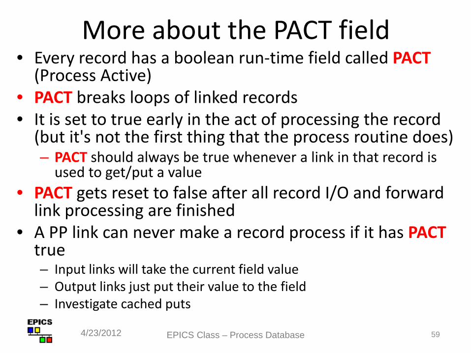
More about the PACT field • Every record has a boolean run-time field called PACT
(Process Active) • PACT breaks loops of linked records • It is set to true early in the act of processing the record
(but it's not the first thing that the process routine does) – PACT should always be true whenever a link in that record is
used to get/put a value • PACT gets reset to false after all record I/O and forward
link processing are finished • A PP link can never make a record process if it has PACT
true – Input links will take the current field value – Output links just put their value to the field – Investigate cached puts
EPICS Class – Process Database 59 4/23/2012
60
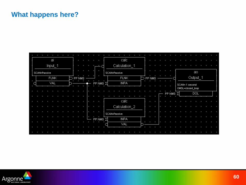
What happens here?
Other Common Fields and Functions
EPICS Class – Process Database 61 4/23/2012
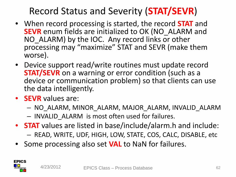
Record Status and Severity (STAT/SEVR) • When record processing is started, the record STAT and
SEVR enum fields are initialized to OK (NO_ALARM and NO_ALARM) by the IOC. Any record links or other processing may “maximize” STAT and SEVR (make them worse).
• Device support read/write routines must update record STAT/SEVR on a warning or error condition (such as a device or communication problem) so that clients can use the data intelligently.
• SEVR values are: – NO_ALARM, MINOR_ALARM, MAJOR_ALARM, INVALID_ALARM – INVALID_ALARM is most often used for failures.
• STAT values are listed in base/include/alarm.h and include: – READ, WRITE, UDF, HIGH, LOW, STATE, COS, CALC, DISABLE, etc
• Some processing also set VAL to NaN for failures.
4/23/2012 62 EPICS Class – Process Database
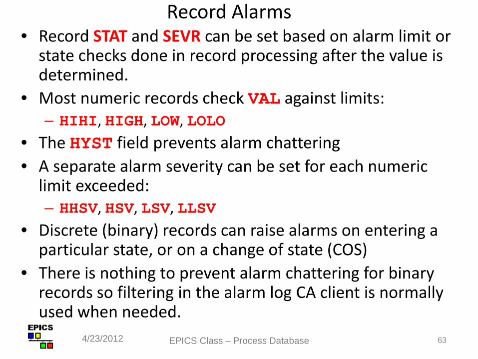
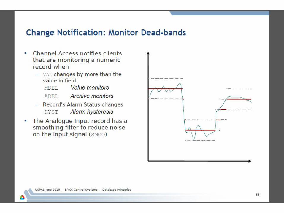
Record Alarms • Record STAT and SEVR can be set based on alarm limit or
state checks done in record processing after the value is determined.
• Most numeric records check VAL against limits: – HIHI, HIGH, LOW, LOLO
• The HYST field prevents alarm chattering • A separate alarm severity can be set for each numeric
limit exceeded: – HHSV, HSV, LSV, LLSV
• Discrete (binary) records can raise alarms on entering a particular state, or on a change of state (COS)
• There is nothing to prevent alarm chattering for binary records so filtering in the alarm log CA client is normally used when needed.
4/23/2012 63 EPICS Class – Process Database
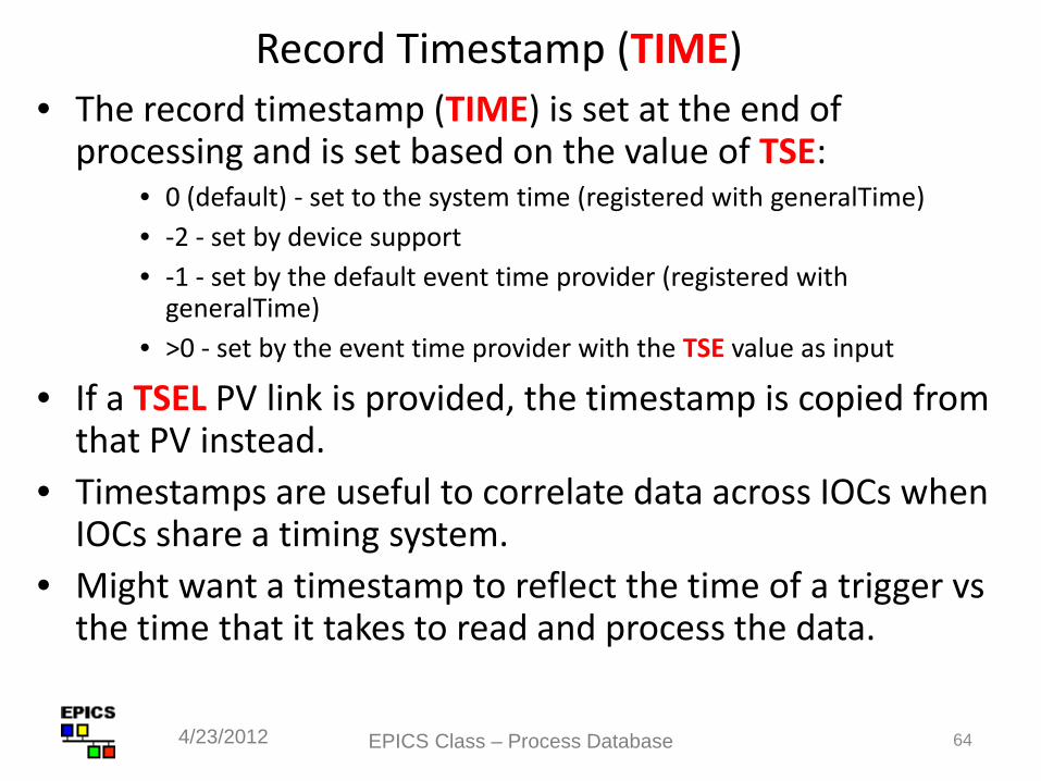
Record Timestamp (TIME) • The record timestamp (TIME) is set at the end of
processing and is set based on the value of TSE: • 0 (default) - set to the system time (registered with generalTime) • -2 - set by device support • -1 - set by the default event time provider (registered with
generalTime) • >0 - set by the event time provider with the TSE value as input
• If a TSEL PV link is provided, the timestamp is copied from that PV instead.
• Timestamps are useful to correlate data across IOCs when IOCs share a timing system.
• Might want a timestamp to reflect the time of a trigger vs the time that it takes to read and process the data.
4/23/2012 64 EPICS Class – Process Database
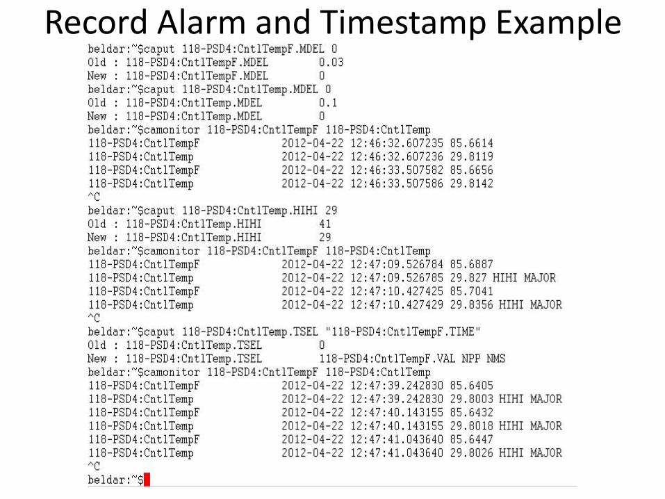
Record Alarm and Timestamp Example
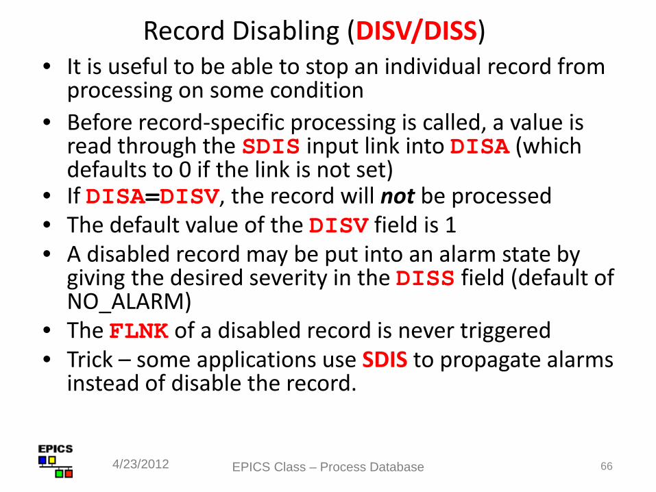
Record Disabling (DISV/DISS) • It is useful to be able to stop an individual record from
processing on some condition • Before record-specific processing is called, a value is
read through the SDIS input link into DISA (which defaults to 0 if the link is not set)
• If DISA=DISV, the record will not be processed • The default value of the DISV field is 1 • A disabled record may be put into an alarm state by
giving the desired severity in the DISS field (default of NO_ALARM)
• The FLNK of a disabled record is never triggered • Trick – some applications use SDIS to propagate alarms
instead of disable the record.
4/23/2012 66 EPICS Class – Process Database
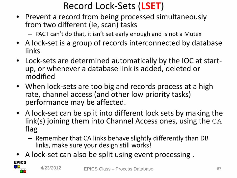
Record Lock-Sets (LSET) • Prevent a record from being processed simultaneously
from two different (ie, scan) tasks – PACT can’t do that, it isn’t set early enough and is not a Mutex
• A lock-set is a group of records interconnected by database links
• Lock-sets are determined automatically by the IOC at start-up, or whenever a database link is added, deleted or modified
• When lock-sets are too big and records process at a high rate, channel access (and other low priority tasks) performance may be affected.
• A lock-set can be split into different lock sets by making the link(s) joining them into Channel Access ones, using the CA flag – Remember that CA links behave slightly differently than DB
links, make sure your design still works! • A lock-set can also be split using event processing .
4/23/2012 67 EPICS Class – Process Database
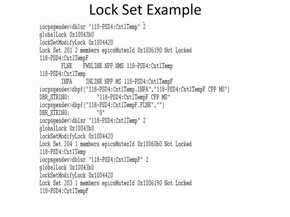
Lock Set Example
69
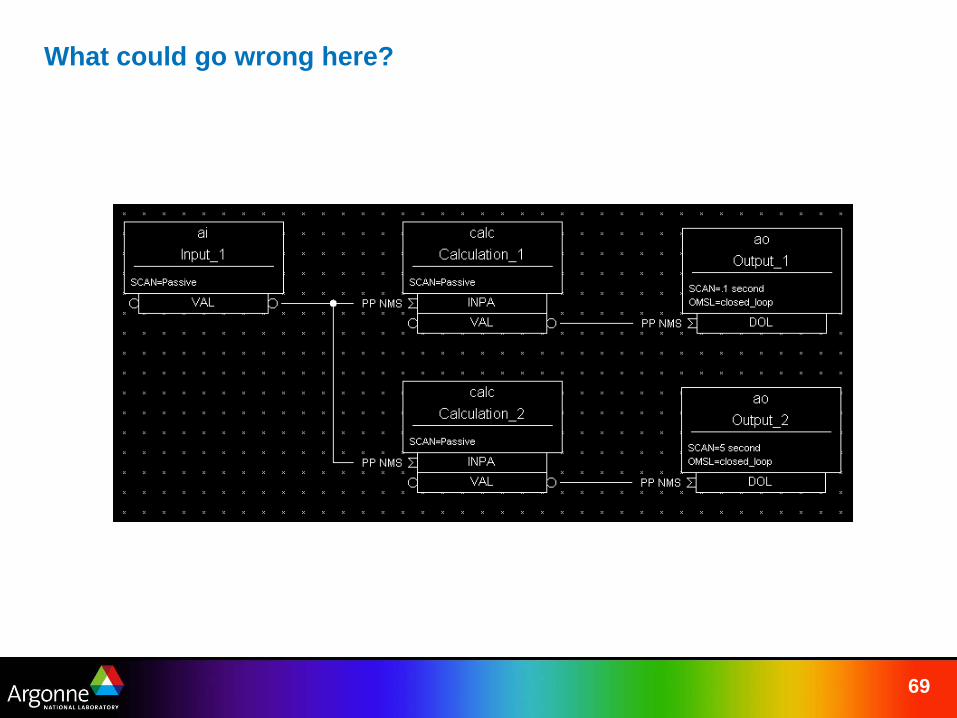
What could go wrong here?
75
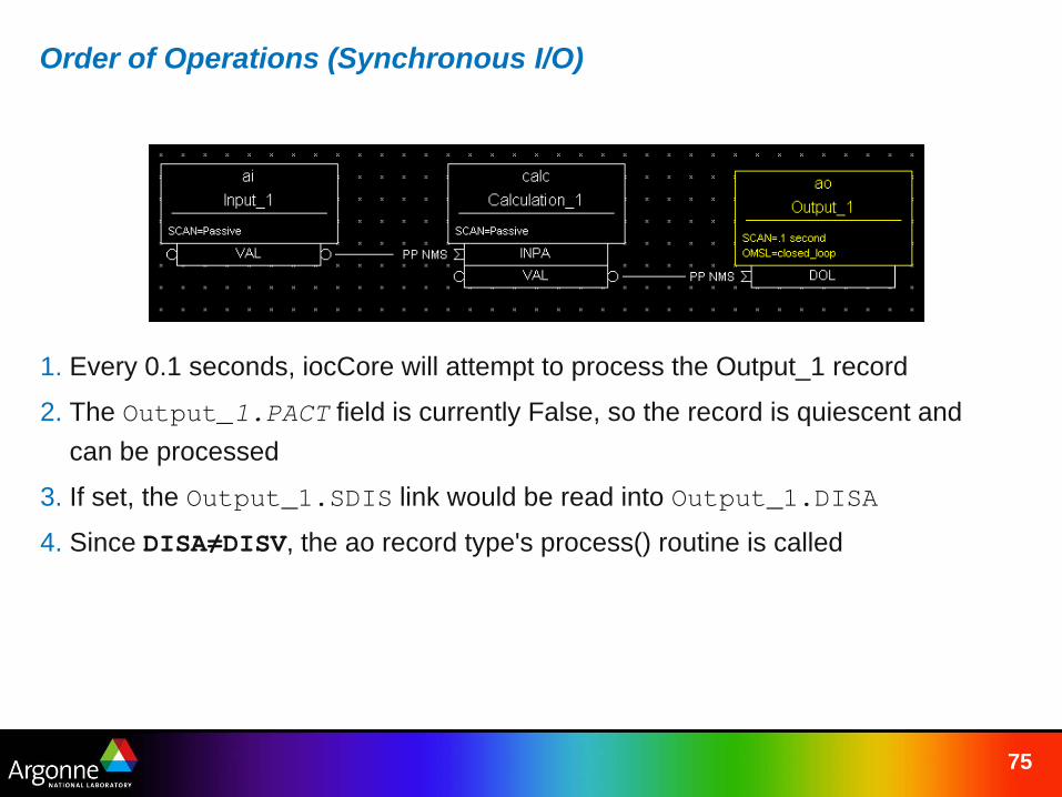
Order of Operations (Synchronous I/O)
1. Every 0.1 seconds, iocCore will attempt to process the Output_1 record
2. The Output_1.PACT field is currently False, so the record is quiescent and can be processed
3. If set, the Output_1.SDIS link would be read into Output_1.DISA
4. Since DISA≠DISV, the ao record type's process() routine is called
76
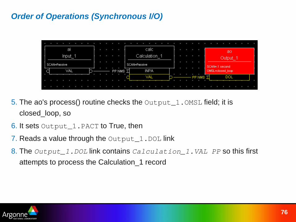
Order of Operations (Synchronous I/O)
5. The ao's process() routine checks the Output_1.OMSL field; it is closed_loop, so
6. It sets Output_1.PACT to True, then
7. Reads a value through the Output_1.DOL link
8. The Output_1.DOL link contains Calculation_1.VAL PP so this first attempts to process the Calculation_1 record
77
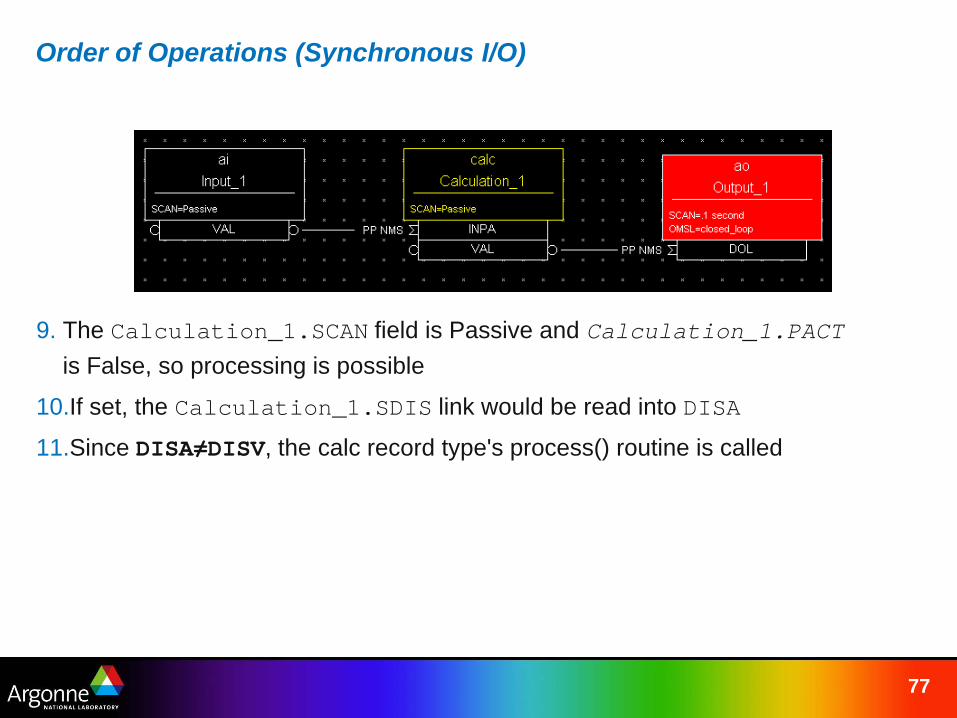
Order of Operations (Synchronous I/O)
9. The Calculation_1.SCAN field is Passive and Calculation_1.PACT is False, so processing is possible
10.If set, the Calculation_1.SDIS link would be read into DISA
11.Since DISA≠DISV, the calc record type's process() routine is called

78
Order of Operations (Synchronous I/O)
12.The calc's process() routine sets Calculation_1.PACT to True, then
13.Starts a loop to read values from the links INPA through INPL
14.The Calculation_1.INPA link is set to Input_1.VAL PP so this first attempts to process the Input_1 record
79
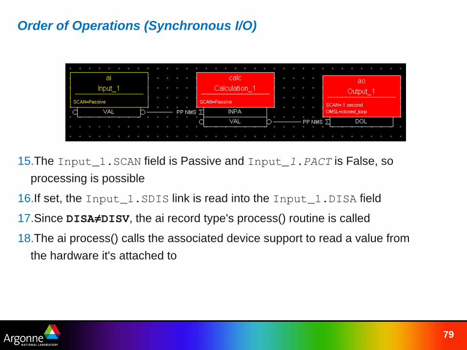
Order of Operations (Synchronous I/O)
15.The Input_1.SCAN field is Passive and Input_1.PACT is False, so processing is possible
16.If set, the Input_1.SDIS link is read into the Input_1.DISA field
17.Since DISA≠DISV, the ai record type's process() routine is called
18.The ai process() calls the associated device support to read a value from the hardware it's attached to
80
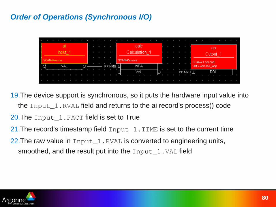
Order of Operations (Synchronous I/O)
19.The device support is synchronous, so it puts the hardware input value into the Input_1.RVAL field and returns to the ai record's process() code
20.The Input_1.PACT field is set to True
21.The record's timestamp field Input_1.TIME is set to the current time
22.The raw value in Input_1.RVAL is converted to engineering units, smoothed, and the result put into the Input_1.VAL field
81
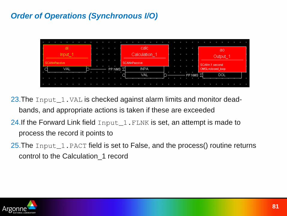
Order of Operations (Synchronous I/O)
23.The Input_1.VAL is checked against alarm limits and monitor dead-bands, and appropriate actions is taken if these are exceeded
24.If the Forward Link field Input_1.FLNK is set, an attempt is made to process the record it points to
25.The Input_1.PACT field is set to False, and the process() routine returns control to the Calculation_1 record
82
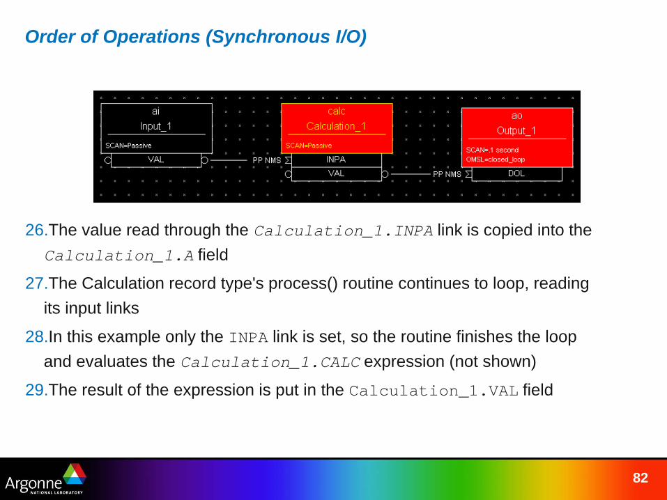
Order of Operations (Synchronous I/O)
26.The value read through the Calculation_1.INPA link is copied into the Calculation_1.A field
27.The Calculation record type's process() routine continues to loop, reading its input links
28.In this example only the INPA link is set, so the routine finishes the loop and evaluates the Calculation_1.CALC expression (not shown)
29.The result of the expression is put in the Calculation_1.VAL field
83
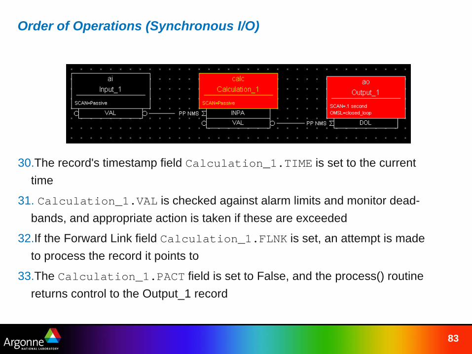
Order of Operations (Synchronous I/O)
30.The record's timestamp field Calculation_1.TIME is set to the current time
31. Calculation_1.VAL is checked against alarm limits and monitor dead-bands, and appropriate action is taken if these are exceeded
32.If the Forward Link field Calculation_1.FLNK is set, an attempt is made to process the record it points to
33.The Calculation_1.PACT field is set to False, and the process() routine returns control to the Output_1 record
84
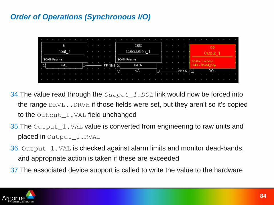
Order of Operations (Synchronous I/O)
34.The value read through the Output_1.DOL link would now be forced into the range DRVL..DRVH if those fields were set, but they aren't so it's copied to the Output_1.VAL field unchanged
35.The Output_1.VAL value is converted from engineering to raw units and placed in Output_1.RVAL
36. Output_1.VAL is checked against alarm limits and monitor dead-bands, and appropriate action is taken if these are exceeded
37.The associated device support is called to write the value to the hardware
85
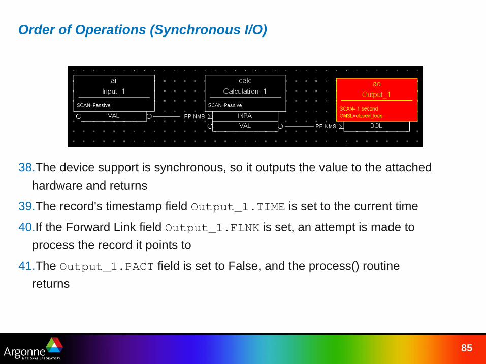
Order of Operations (Synchronous I/O)
38.The device support is synchronous, so it outputs the value to the attached hardware and returns
39.The record's timestamp field Output_1.TIME is set to the current time
40.If the Forward Link field Output_1.FLNK is set, an attempt is made to process the record it points to
41.The Output_1.PACT field is set to False, and the process() routine returns