Embed Size (px)
Citation preview
EPICS Collaboration Meeting
Timing Workshop
April 24, 2012
EPICS Timing Workshop, April 24, 2012
General Goals of our Discussion
• Starting with the requirements for timing systems Overview of linac FEL timing requirements Overview of storage ring light source timing requirements Any other accelerator systems?
• Are there new requirements for next generation machines? Improved performance in terms of stability, drift over long distances? Higher repetition rates, broadcasting more complex timing patterns?
• Awareness of multiple beam destinations and AC power timeslot issues. Integration and synchronization issues with other subsystems (LLRF,
feedbacks, MPS, …) • Overview of currently available hardware • Outlook for new hardware
Form-factors for discrete modules Embedded FPGA timing receivers
Slide 2
EPICS Timing Workshop, April 24, 2012
Cont. - General Goals of our Discussion 2.
• Overview of currently supported software Available drivers Support for different platforms, operating systems Timing dependant software such as Beam Synchronous Data Acquisition
(BSA) and Beam Line Data (BLD). • Overview of current architecture of EPICS timing software
Limitations of record processing Proposed architecture of C code for faster performance
• List of requested new features or improvements Hardware Firmware Software
• Operational issues and experience Improved timing system diagnostics User interfaces and operator GUIs
Slide 3
EPICS Timing Workshop, April 24, 2012
Not Covered
• Will not be giving a general timing tutorial!
• This is a workshop intended for people working in the field with an interest toward defining new requirements and new areas of development
Slide 4
EPICS Timing Workshop, April 24, 2012
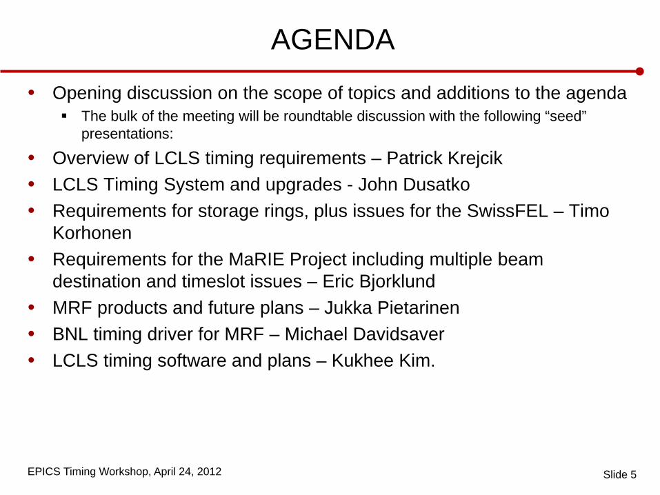
AGENDA
• Opening discussion on the scope of topics and additions to the agenda The bulk of the meeting will be roundtable discussion with the following “seed”
presentations:
• Overview of LCLS timing requirements – Patrick Krejcik • LCLS Timing System and upgrades - John Dusatko • Requirements for storage rings, plus issues for the SwissFEL – Timo
Korhonen • Requirements for the MaRIE Project including multiple beam
destination and timeslot issues – Eric Bjorklund • MRF products and future plans – Jukka Pietarinen • BNL timing driver for MRF – Michael Davidsaver • LCLS timing software and plans – Kukhee Kim.
Slide 5
EPICS Timing Workshop, April 24, 2012
Logistics
• Bldg 48 Redwood A Meeting Room • 01:30pm Timing Workshop • 02:30pm Coffee Break • 03:00pm Workshop (cont.) • 05:00pm Workshop ends • 06.30pm dinner - TBA
Slide 6
EPICS Timing Workshop, April 24, 2012
LCLS Timing Requirements Overview
Timing Workshop
April 24, 2012
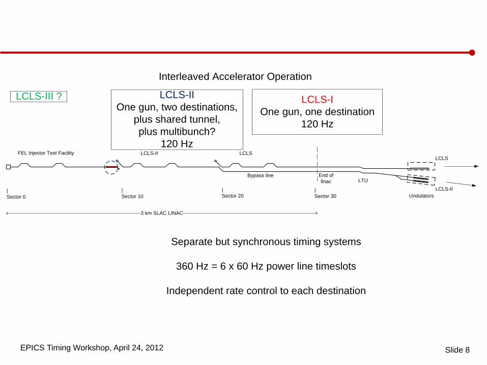
EPICS Timing Workshop, April 24, 2012 Slide 8
LCLS
LCLS-II
End oflinac
LCLSLCLS-II
Bypass line
|Sector 0
|Sector 10
|Sector 20
|Sector 30
FEL Injector Test Facility
3 km SLAC LINAC
LTU
Undulators
Interleaved Accelerator Operation
LCLS-III ? LCLS-IOne gun, one destination
120 Hz
LCLS-IIOne gun, two destinations,
plus shared tunnel, plus multibunch?
120 Hz
Separate but synchronous timing systems
360 Hz = 6 x 60 Hz power line timeslots
Independent rate control to each destination
EPICS Timing Workshop, April 24, 2012
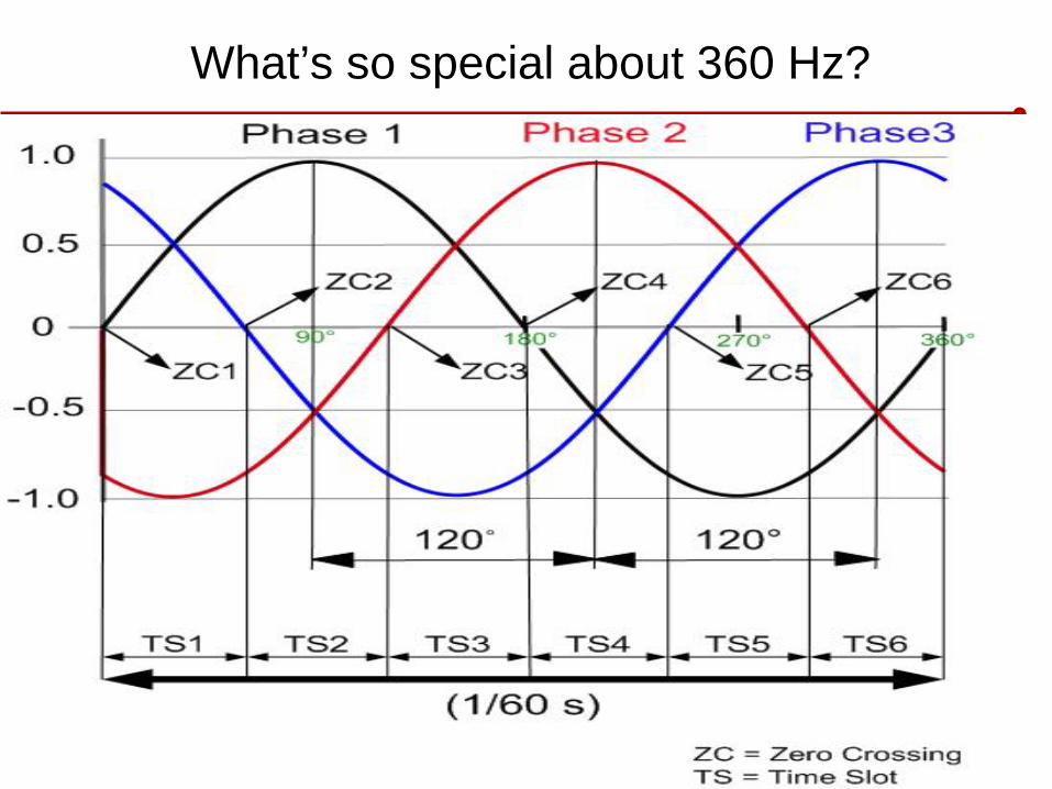
What’s so special about 360 Hz?
EPICS Timing Workshop, April 24, 2012
Timing in the Context of the Overall Controls Architecture
Slide 10
SafetySystems
Status Info
SafetySystems
Status Info
ApplicationServers
ApplicationServers
RelationalDatabasesRelationalDatabases
OperatorConsoleServers
OperatorConsoleServers
ServersServers
Link
Nod
eLi
nkN
ode
EV
Rdevice
modules
IOC
EV
Rdevice
modules
IOC
EV
Rdevice
modules
IOC
EV
Rdevice
modules
IOC IOC
EV
R Link
Nod
e
Link
Nod
e
CratesVME, mTCA ...
Embedded Processors ... MPS
FeedbackProcessor
Timing
Channel Access Backbone
Mitigationdevices
MPS Network
Feedback Network
Timing Network
OperatorConsoleServers
ApplicationServers
SoftIOCs
Router
RelationalDatabases Servers
Intermediary Network
Public Network
To Photon Network
Gateway Servers
RF Synchronization
Controls System Overview
EV
Rdevice
modules
IOC
EV
Rdevice
modules
IOC Input
devices
To LCLS-I
LCLS-I Network
PLC
ProcessControl
SafetySystems
Status Info
EPICS Timing Workshop, April 24, 2012
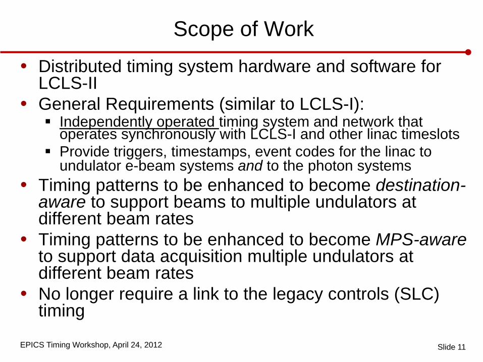
Scope of Work
• Distributed timing system hardware and software for LCLS-II
• General Requirements (similar to LCLS-I): Independently operated timing system and network that
operates synchronously with LCLS-I and other linac timeslots Provide triggers, timestamps, event codes for the linac to
undulator e-beam systems and to the photon systems • Timing patterns to be enhanced to become destination-
aware to support beams to multiple undulators at different beam rates
• Timing patterns to be enhanced to become MPS-aware to support data acquisition multiple undulators at different beam rates
• No longer require a link to the legacy controls (SLC) timing
Slide 11
EPICS Timing Workshop, April 24, 2012
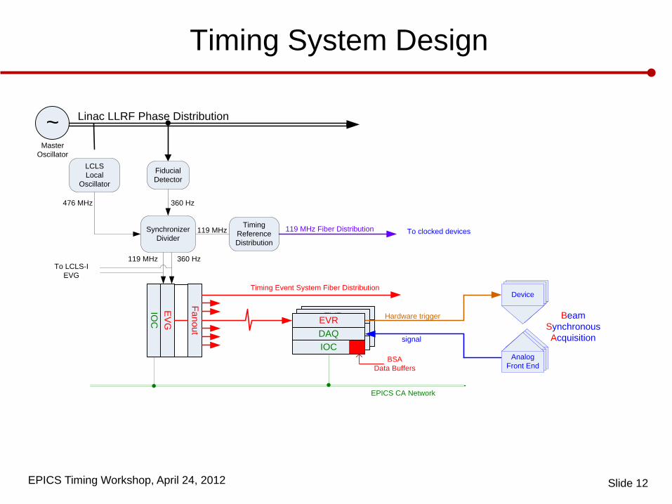
Device
AnalogFront End
Device
AnalogFront End
EVRDAQIOC
EVRDAQIOC
Linac LLRF Phase Distribution~
LCLSLocal
Oscillator
SynchronizerDivider
FiducialDetector
EV
G
Fanout
IOC
Timing ReferenceDistribution
360 Hz
119 MHz 360 Hz
119 MHz 119 MHz Fiber Distribution
Timing Event System Fiber Distribution
EPICS CA Network
476 MHz
Device
AnalogFront End
Hardware trigger
signal
Beam SynchronousAcquisition
BSAData Buffers
To clocked devices
To LCLS-IEVG
EVRDAQIOC
MasterOscillator
Timing System Design
Slide 12
EPICS Timing Workshop, April 24, 2012
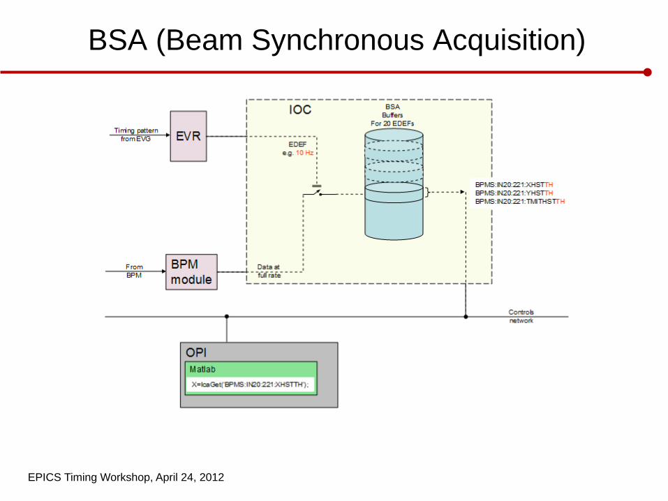
BSA (Beam Synchronous Acquisition)
EPICS Timing Workshop, April 24, 2012
Design • Design based on mature LCLS-I system design • Using COTS components
MicroResearch Finland Event Receivers, VME, PMC …
• EVRs BPMs: 1 per IOC, 5 BPMs per IOC both SL and RF. BPMS and BCS Hard and Soft lines processed separately.
• RTMs For BPMs only. Strip lines require two triggers per BPM (10/crate) RF BPMs one.
• CV01 VME control for CAMAC. Only first ten sectors costed. No one assigned as system lead.
• FODUs and Fiber Optic Connector Panels For fiber distribution. Sectors 20-30 FODUs have spare capacity for now.
• FO Jumpers Trunks estimated through DeSalvo. Jumpers necessary to connect to EVRs and complete infrastructure for timing
distribution
• TRD - Timing Referene Distribution. 119MHz with fiducial for MPS, BCS and diagnostic Toroids
Slide 14
EPICS Timing Workshop, April 24, 2012
Lessons Learned from LCLS-I
• All fiber terminations should be done only by
qualified Technicians • Multimode fiber should be installed for long haul
fiber runs in the linac • Long haul fiber installation design should
incorporate FODU termination boxes • Timing system event codes should be made aware
of MPS trips so that data acquisition by BPMs etc. is correctly handled
• Plan for greater flexibility in new event codes for photon users
Slide 15
EPICS Timing Workshop, April 24, 2012
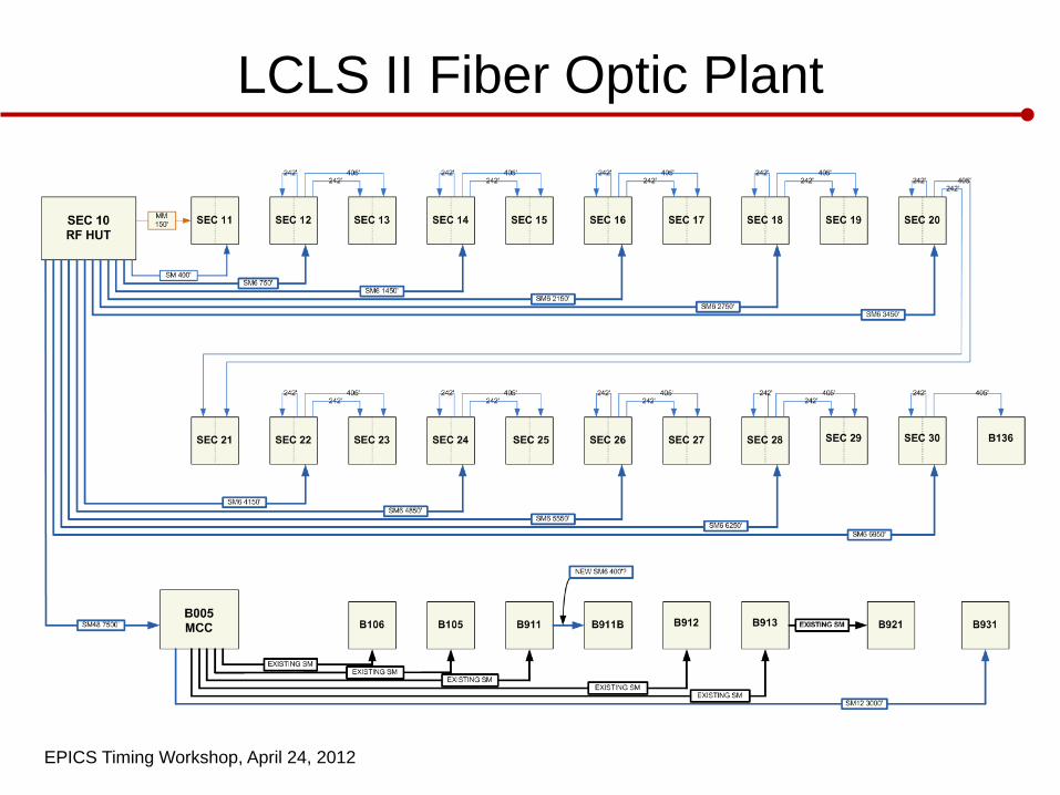
LCLS II Fiber Optic Plant
EPICS Timing Workshop, April 24, 2012
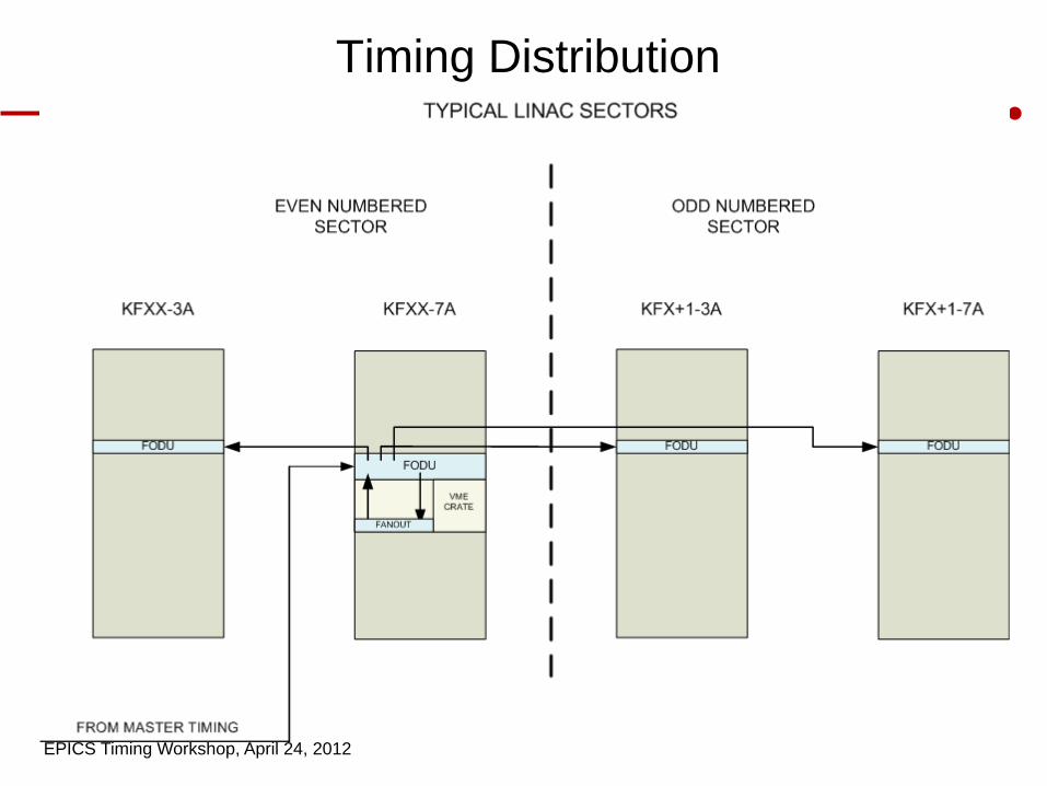
Timing Distribution
EPICS Timing Workshop, April 24, 2012
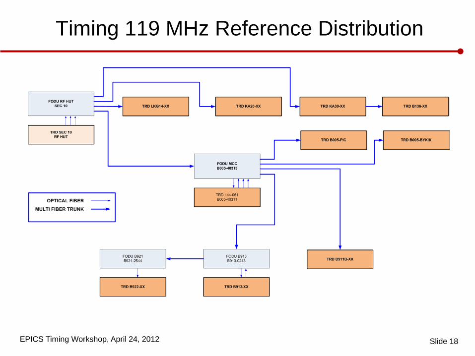
Timing 119 MHz Reference Distribution
Slide 18
EPICS Timing Workshop, April 24, 2012
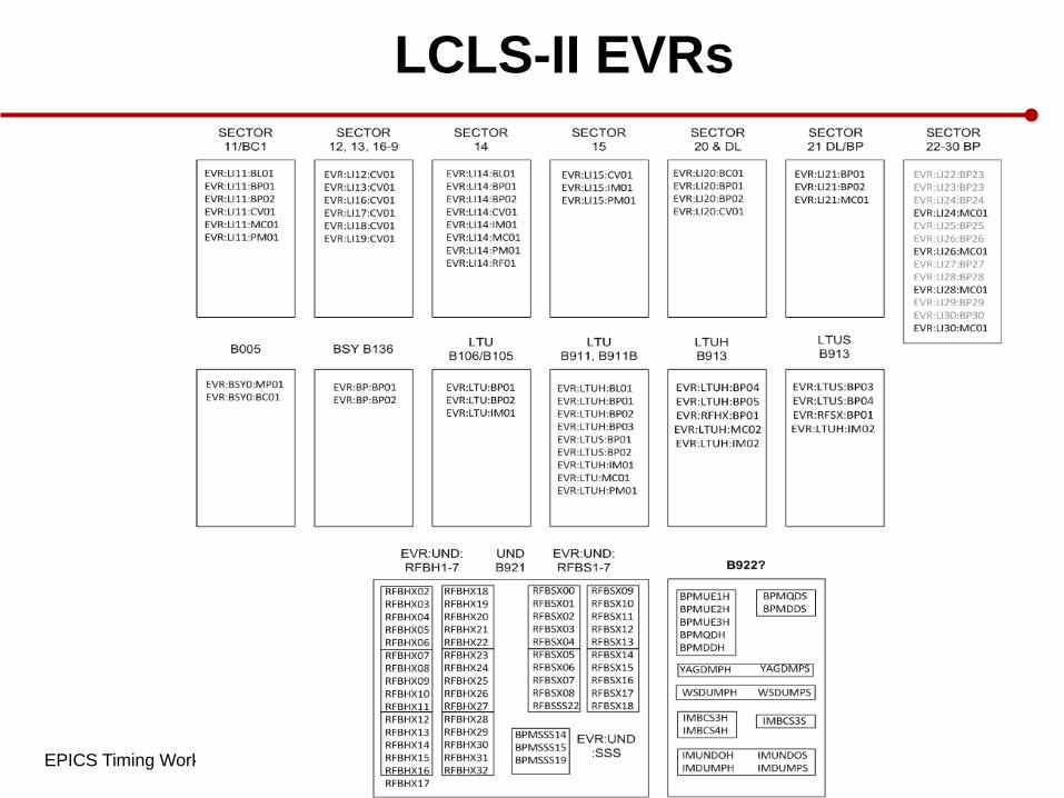
LCLS-II EVRs
EPICS Timing Workshop, April 24, 2012
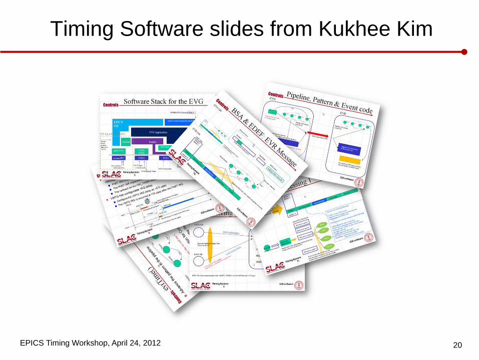
Timing Software slides from Kukhee Kim
20
EPICS Timing Workshop, April 24, 2012
EPICS Timing Workshop, April 24, 2012 Meeting Name/Presentation
Title Location, Date
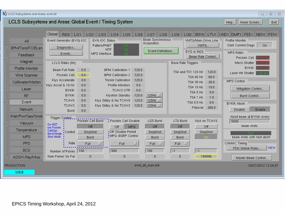
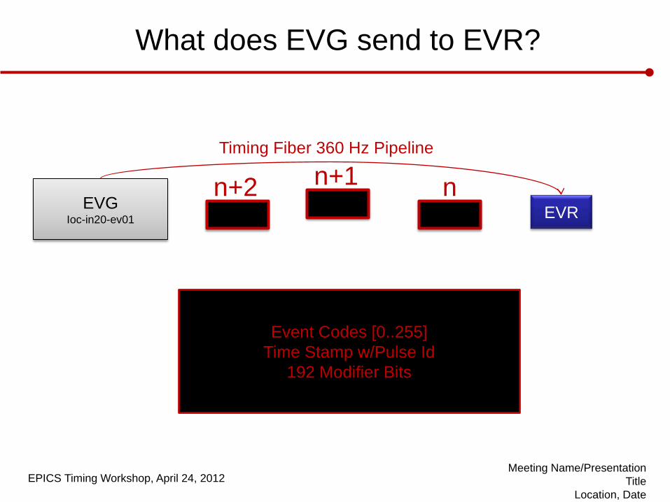
EVG Ioc-in20-ev01 EVR
What does EVG send to EVR?
Timing Fiber 360 Hz Pipeline
n n+1 n+2
Event Codes [0..255] Time Stamp w/Pulse Id
192 Modifier Bits
EPICS Timing Workshop, April 24, 2012
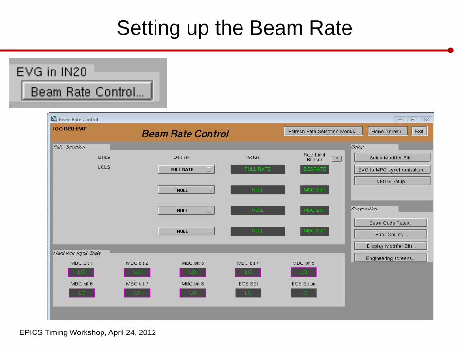
Setting up the Beam Rate
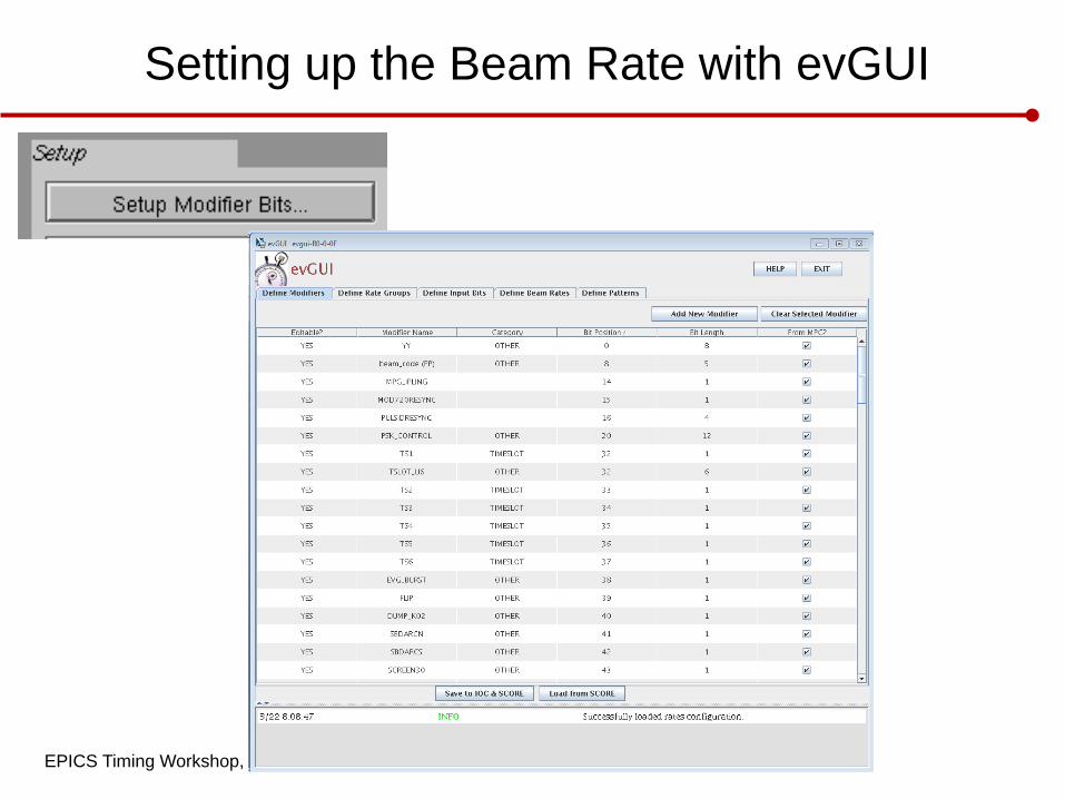
EPICS Timing Workshop, April 24, 2012
Setting up the Beam Rate with evGUI
EPICS Timing Workshop, April 24, 2012
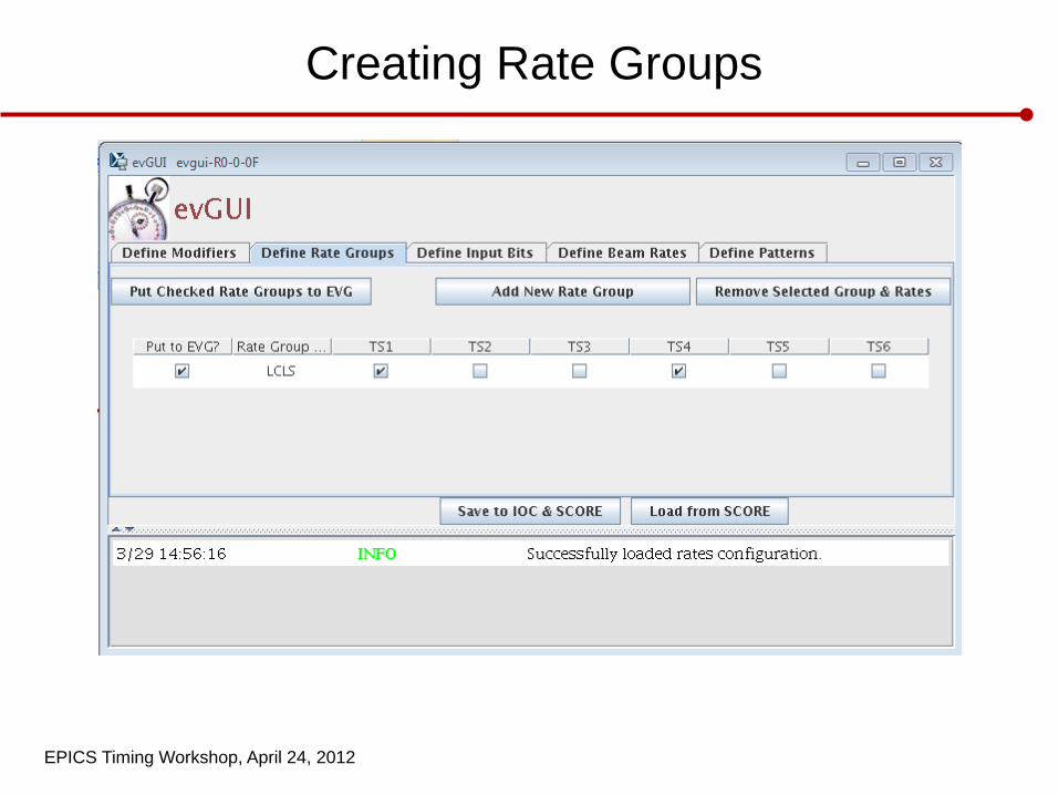
Creating Rate Groups
EPICS Timing Workshop, April 24, 2012
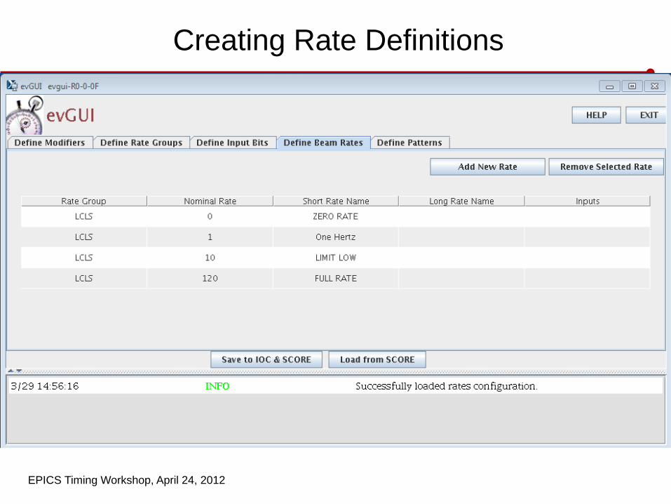
Creating Rate Definitions
EPICS Timing Workshop, April 24, 2012
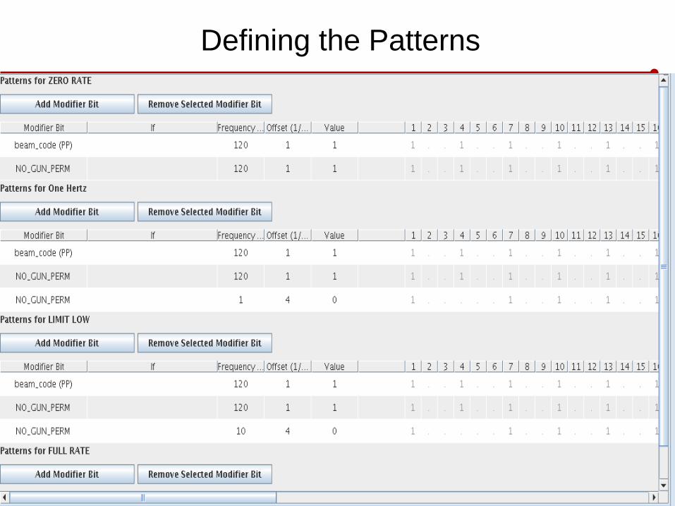
Defining the Patterns
EPICS Timing Workshop, April 24, 2012
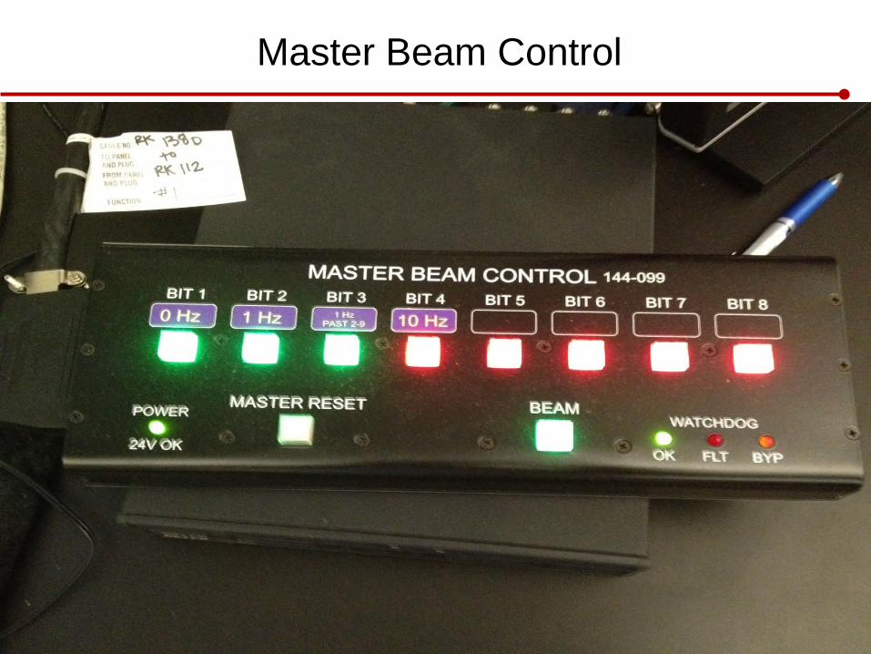
Master Beam Control
Meeting Name/Presentation Title
Location, Date
EPICS Timing Workshop, April 24, 2012
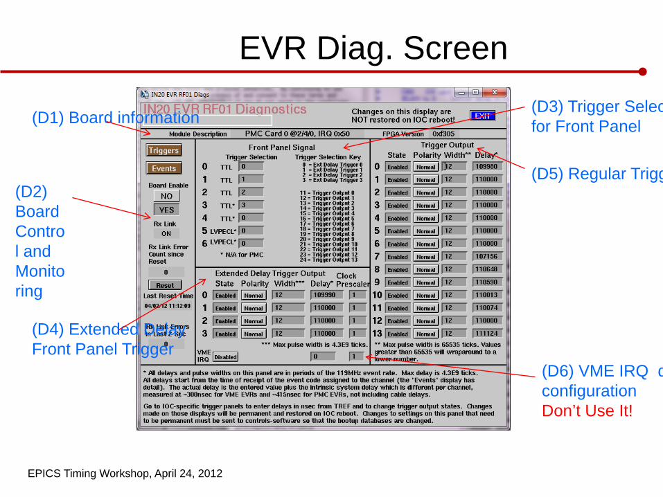
EVR Diag. Screen
(D2) Board Control and Monitoring
(D1) Board information (D3) Trigger Selec for Front Panel
(D4) Extended Delay Front Panel Trigger
(D5) Regular Trigg
(D6) VME IRQ dconfiguration Don’t Use It!
EPICS Timing Workshop, April 24, 2012
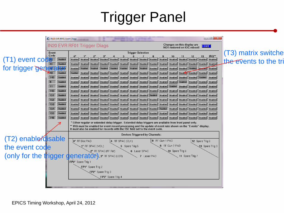
Trigger Panel
(T1) event code for trigger generator
(T2) enable/disable the event code (only for the trigger generator)
(T3) matrix switches the events to the tri
EPICS Timing Workshop, April 24, 2012
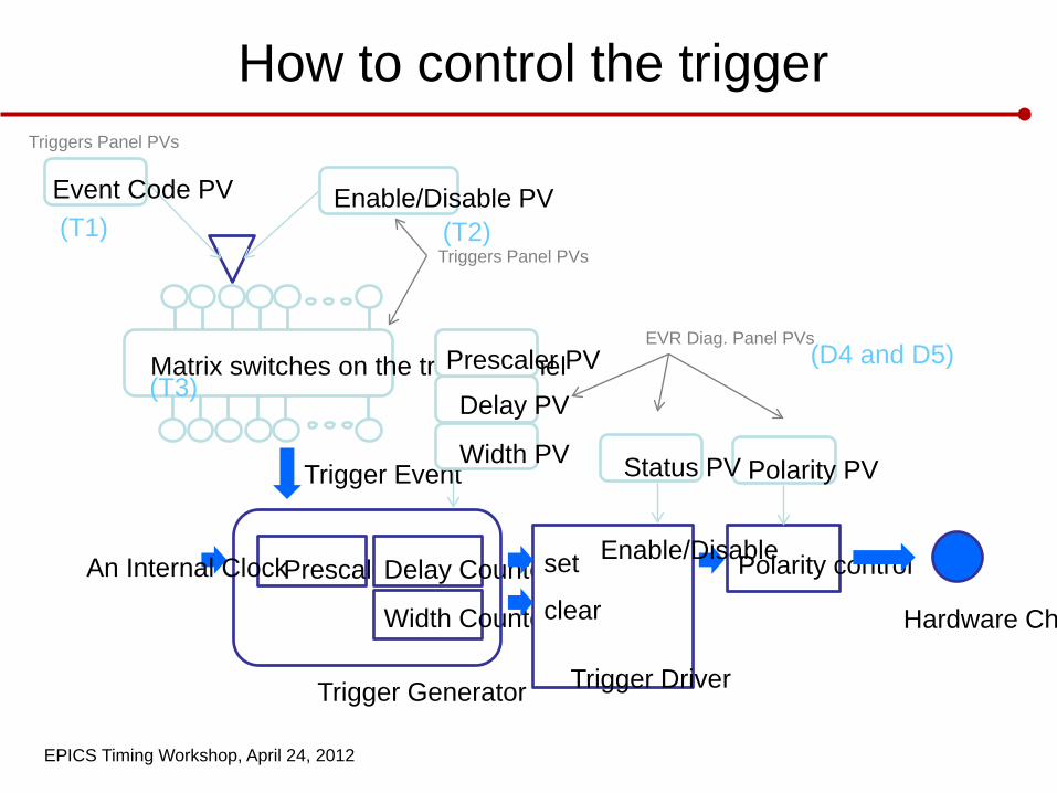
How to control the trigger
Polarity control
Polarity PV
Hardware Ch
Prescaler Delay Counter
Width Counter
set
clear
Trigger Driver
Status PV
Enable/Disable
Trigger Generator
An Internal Clock
Trigger Event
Matrix switches on the trigger panel
Event Code PV Enable/Disable PV
Prescaler PV
Delay PV
Width PV
EVR Diag. Panel PVs
Triggers Panel PVs
Triggers Panel PVs
(T3)
(T1) (T2)
(D4 and D5)
EPICS Timing Workshop, April 24, 2012
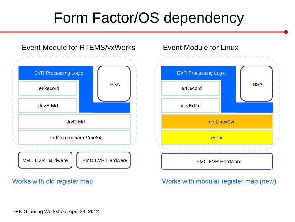
Form Factor/OS dependency
VME EVR Hardware PMC EVR Hardware
mrfCommon/mrfVme64
drvErMrf
devErMrf
erRecord BSA
EVR Processing Logic
Event Module for RTEMS/vxWorks
erapi
drvLinuxEvr
devErMrf
erRecord BSA
EVR Processing Logic
Event Module for Linux
PMC EVR Hardware
Works with old register map Works with modular register map (new)
EPICS Timing Workshop, April 24, 2012
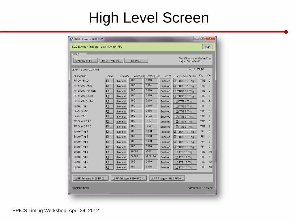
High Level Screen
EPICS Timing Workshop, April 24, 2012
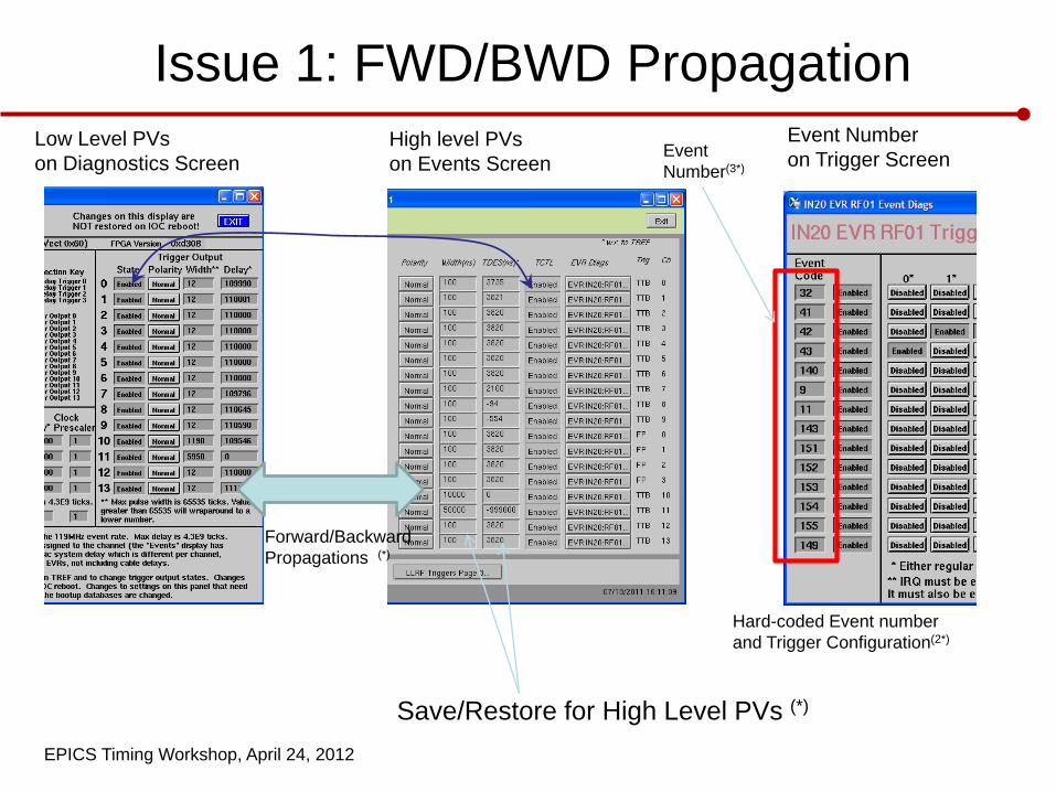
Issue 1: FWD/BWD Propagation Low Level PVs on Diagnostics Screen
High level PVs on Events Screen
Event Number on Trigger Screen
Forward/Backward Propagations (*)
Hard-coded Event number and Trigger Configuration(2*)
Save/Restore for High Level PVs (*)
Event Number(3*)
EPICS Timing Workshop, April 24, 2012
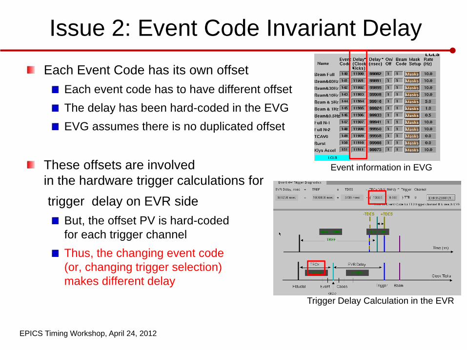
Issue 2: Event Code Invariant Delay Each Event Code has its own offset
Each event code has to have different offset The delay has been hard-coded in the EVG EVG assumes there is no duplicated offset
These offsets are involved in the hardware trigger calculations for
trigger delay on EVR side But, the offset PV is hard-coded for each trigger channel Thus, the changing event code (or, changing trigger selection) makes different delay
Event information in EVG
Trigger Delay Calculation in the EVR
EPICS Timing Workshop, April 24, 2012
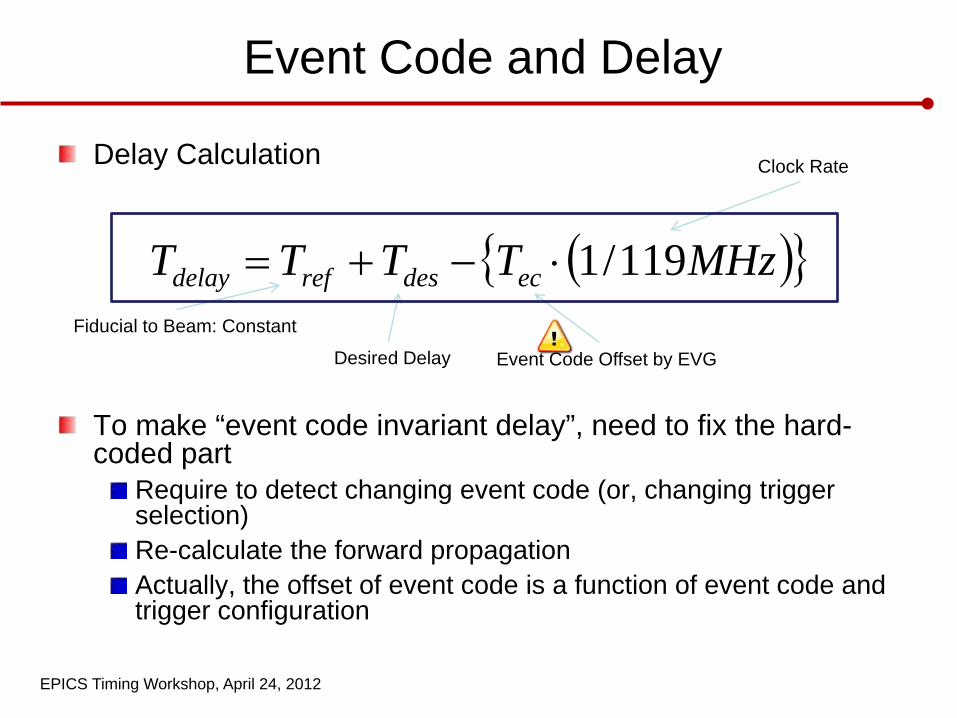
Event Code and Delay
Delay Calculation
To make “event code invariant delay”, need to fix the hard-coded part
Require to detect changing event code (or, changing trigger selection) Re-calculate the forward propagation Actually, the offset of event code is a function of event code and trigger configuration
( ){ }MHzTTTT ecdesrefdelay 119/1⋅−+=Fiducial to Beam: Constant
Desired Delay Event Code Offset by EVG
Clock Rate

EPICS Timing Workshop, April 24, 2012
What is the Timeslot
• Zero Crossings at AC 3 phases lead out the 6 time slots
• Same Timeslot in different peroid shows exactly same AC phase configuration.
• Active Timeslot LCLS: TS1 and TS4 FACET: TS2 and TS5 XTA: TS3 and
TS6
• Primary Timeslot
EPICS Timing Workshop, April 24, 2012
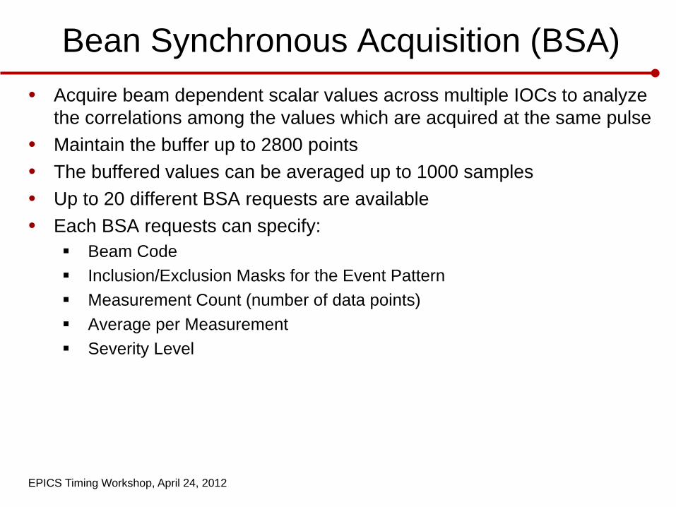
Bean Synchronous Acquisition (BSA) • Acquire beam dependent scalar values across multiple IOCs to analyze
the correlations among the values which are acquired at the same pulse • Maintain the buffer up to 2800 points • The buffered values can be averaged up to 1000 samples • Up to 20 different BSA requests are available • Each BSA requests can specify:
Beam Code Inclusion/Exclusion Masks for the Event Pattern Measurement Count (number of data points) Average per Measurement Severity Level
EPICS Timing Workshop, April 24, 2012
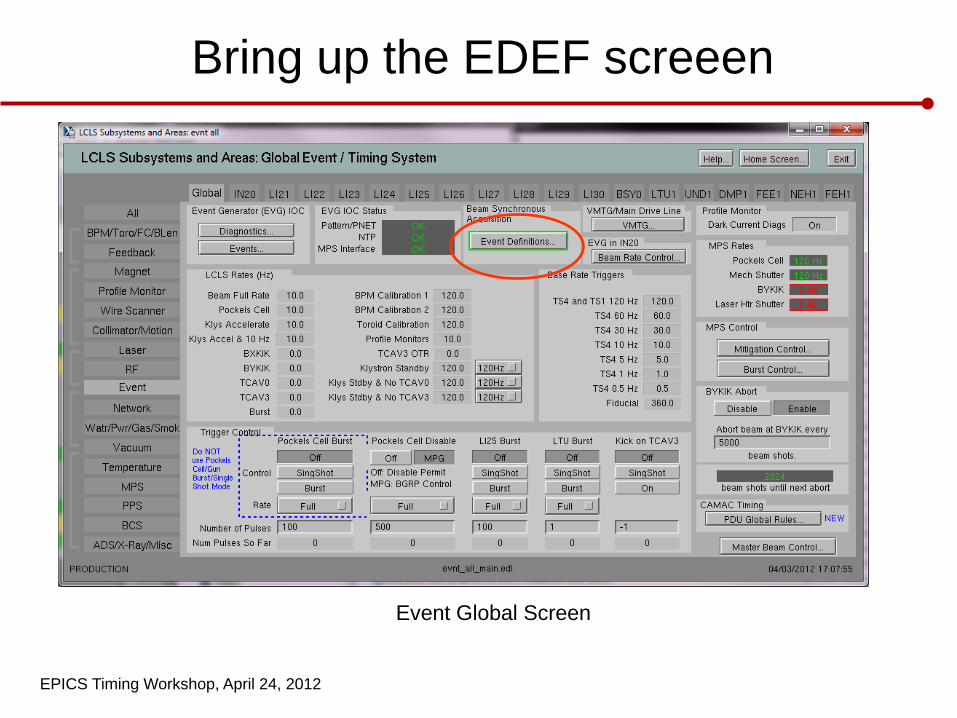
Bring up the EDEF screeen
Event Global Screen
EPICS Timing Workshop, April 24, 2012
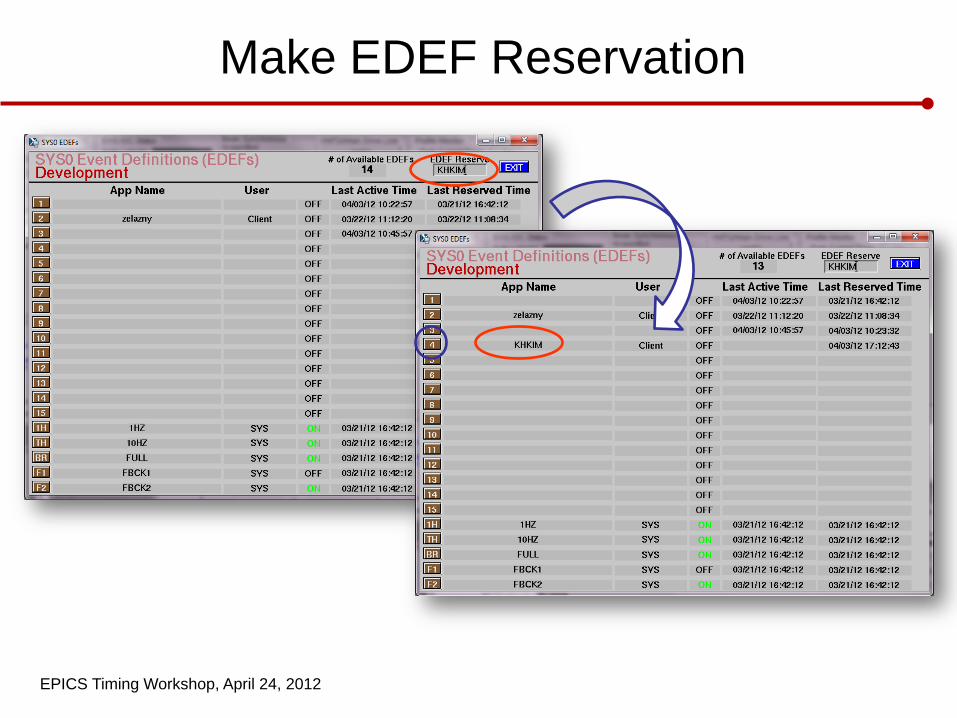
Make EDEF Reservation
EPICS Timing Workshop, April 24, 2012
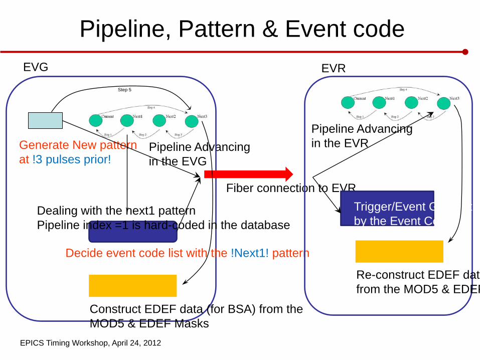
Pipeline, Pattern & Event code
Pipeline Advancing in the EVG
Generate New pattern at !3 pulses prior!
Step 5
Decide event code list with the !Next1! pattern
Dealing with the next1 pattern Pipeline index =1 is hard-coded in the database
Fiber connection to EVR Trigger/Event Generatioby the Event Code
Pipeline Advancing in the EVR
EVG EVR
Construct EDEF data (for BSA) from the MOD5 & EDEF Masks
Re-construct EDEF data from the MOD5 & EDEF
EPICS Timing Workshop, April 24, 2012
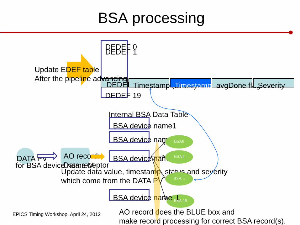
BSA processing
DEDEF 0 DEDEF 1
DEDEF 19 DEDEF n Timestamp (active) Timestamp (Init) avgDone flag Severity
DATA PV AO record: Data receptor
BSA device name1
Update EDEF table After the pipeline advancing
BSA device name2
BSA device name M for BSA device name M
Internal BSA Data Table
Update data value, timestamp, status and severity which come from the DATA PV
BSA0
BSA1
BSA n
BSA 19 BSA device name L
AO record does the BLUE box and make record processing for correct BSA record(s).
EPICS Timing Workshop, April 24, 2012
Glossary
• Beam Code – Part of the PNET broadcast. A set of 5 modifier bits. LCLS runs on beam code 1. • Beam Rate Control – The act of selecting a Rate Definition within a Rate Group. • BGRP (Beam Group) – MPG analogous to an EVG Rate Group • BSA (Beam Synchronous Acquisition) – The act of filling buffers on an IOC at a specific specified time.
• Burst Mode – An operating procedure where an operator requests n pulses followed by zero rate. • Event Codes – Part of the packet the EVG sends to the EVR. There are 256 event codes: [0..255]. • Event Definition – A way to reserve a set of buffers used by BSA. • Event System – Describes the way timing of beam pulses is set up. • EVG (Event Generator) – IOC that passes event codes, time stamps, and modifier bits to the EVR. • EVR (Event Receiver) – A card in an IOC that receives timing data from the EVG. • evGUI (Event Graphical User Interface) – Java GUI used to program Rate Groups, Rate Definitions,
and Modifier Bits for use by the EVG. • Master Beam Control – A box sitting next to most control room OPIs used to select a Rate Definition. • MPG (Master Pattern Generator) – The non-EPICS SLC “micro” to be replaced by the EVG. • Modifier Bits – Part of the packet the EVG send to the EVR. 192 bits of specific timing information. • PABIG (Pattern Bit Generator) – 3D PVs in the EVG used to hold Rate Definnitions x Modifier Bits x
time for each Rate Group.
EPICS Timing Workshop, April 24, 2012
Glossary
• Pattern – Refers to the Beam Code + Modifier Bits • Pipeline – Refers to the continuous stream of data sent from an EVG to the EVR. • PNBN (PNET Bit Numbers aka Timing Pattern Bits) – Defines the names and bit position and bit width
of the Modifier Bits. • PNET (Pulse Id Network) – The network the MPG uses to send out the Timing Pattern. • Pulse Id – A 360Hz counter that gets encoded into the nanoseconds part of the time stamp sent form
the EVG to the EVR. It is used to correlate data so 1 beam pulse can be tracked as it passes by each device.
• Rate Definition – A specific rate to run a specific accelerator, such as “FULL RATE”. • Rate Group – A group of Rate Definitions used by a specific accelerator, such as “LCLS”. • Rate Limiting – The act of selecting a Rate Definition within a Rate Group. • Single Shot Mode – An operating procedure where an operator requests 1 beam pulse followed by
zero rate. • Timing – Short hand term used to describe the Event System. • VMTG (VME Master Trigger Generator) – Part of the EVG that receives the 360Hz fiducial and
generates and interrupt to trigger PABIG PVs.