Embed Size (px)
Citation preview

© Epec Oy
Epec 4W Herman Version 1.02
User's manual
Epec 4W Herman
2 / 148 21.12.2010
MAN000403
Epec Oy reserves all rights for improvements without prior notice Epec Oy Postal address Phone Fax Www Tiedekatu 6 PO Box 194 +358-(0)20-7608 111 +358-(0)20-7608 110 www.epec.fi FI-60320 Seinäjoki, Finland FIN-60120 Seinäjoki, Finland
DOCUMENT VERSION HISTORY Date Explanation
2.6.2009 First published version
15.12.2009 Updated to correspond to the Finnish version which was dated 1.12.2009
12.08.2010 Version 1.02
Updated to correspond to the Finnish version which was dated 16.04.2010
- Optional tilt conrol method
o New parameter (4.6) added
o Tilt up (shift2 + tilt up) is controlled for as long as the buttons are pressed. It does not lock and control stops as soon as the buttons are released.
21.12.2010 Section 1. General updated
Epec 4W Herman
3 / 148 21.12.2010
MAN000403
Epec Oy reserves all rights for improvements without prior notice Epec Oy Postal address Phone Fax Www Tiedekatu 6 PO Box 194 +358-(0)20-7608 111 +358-(0)20-7608 110 www.epec.fi FI-60320 Seinäjoki, Finland FIN-60120 Seinäjoki, Finland
CONTENTS 1 GENERAL ........................................................................................................................... 6
1.1 About this manual ...................................................................................................... 6 1.2 EPEC products .......................................................................................................... 6 1.3 Related documentation .............................................................................................. 6 1.4 Explanations of symbols ............................................................................................ 6 1.5 Safety .............................................................................................................. 7 1.6 Warranty conditions ................................................................................................... 8 1.7 Environmental issues ................................................................................................ 8
2 ABBREVIATIONS AND TERMINOLOGY .......................................................................... 9
3 EPEC 4W HERMAN .......................................................................................................... 10 3.1 Assembly ............................................................................................................ 10 3.2 User interface .......................................................................................................... 11
3.2.1 Handles ....................................................................................................... 11 3.2.2 Display and programming wheel ................................................................. 11
4 CONTROLLING FUNCTIONS .......................................................................................... 13 4.1 Safety lock and safety switch .................................................................................. 13 4.2 Controlling the harvester head functions ................................................................. 13
4.2.1 Controlling eco harvester head ................................................................... 13 4.2.2 Harvester head fully open / open in intermediate positions ........................ 14 4.2.3 Harvester head fully closed / closed to intermediate positions ................... 15 4.2.4 Tilt up/down and tilt floating ......................................................................... 17
4.2.4.1 Adjusting tilt pressure 18 4.3 Controlling delimbing knives .................................................................................... 19
4.3.1 Front knives fully open / open to intermediate positions ............................. 19 4.3.2 Front knives fully closed / closed until the intermediate positions .............. 20 4.3.3 Rear knives fully open / open to intermediate positions .............................. 20 4.3.4 Rear knives fully closed / closed until the intermediate positions ............... 21 4.3.5 Knifes vibration ............................................................................................ 22 4.3.6 Automatic rear knives' control with negative length measurement ............. 25 4.3.7 Adjusting knives' pressure ........................................................................... 26
4.4 Track control (feed tracks / feed rollers). ................................................................. 26 4.4.1 Tracks fully open / open to intermediate positions ...................................... 27 4.4.2 Tracks fully closed / closed until the intermediate positions ....................... 28 4.4.3 Adjusting track pressure .............................................................................. 29
4.5 Rotator and extension (jib) control........................................................................... 29 4.6 Feed control ............................................................................................................ 30
4.6.1 Feed modes ................................................................................................ 31 4.6.2 Automatic cut-to-length ............................................................................... 32 4.6.3 Braking distance .......................................................................................... 33 4.6.4 Stopping advance ........................................................................................ 34 4.6.5 Search pulses .............................................................................................. 34 4.6.6 Saw window ................................................................................................ 35 4.6.7 Minimum top diameter ................................................................................. 35
4.6.7.1 Breaking for minimum top diameter 35 4.6.8 Automatic pre-delimbing ............................................................................. 36 4.6.9 Slipping identification and branch chipper .................................................. 36 4.6.10 Butt end delimbing (butt reversal) and butt end search .............................. 38
4.7 Cutting control .......................................................................................................... 39 4.7.1 Saw function modes in cutting .................................................................... 39 4.7.2 Felling .......................................................................................................... 40
4.7.2.1 Over-cutting during felling 40 4.7.2.2 Releasing tilt during felling 41
Epec 4W Herman
4 / 148 21.12.2010
MAN000403
Epec Oy reserves all rights for improvements without prior notice Epec Oy Postal address Phone Fax Www Tiedekatu 6 PO Box 194 +358-(0)20-7608 111 +358-(0)20-7608 110 www.epec.fi FI-60320 Seinäjoki, Finland FIN-60120 Seinäjoki, Finland
4.7.2.3 Stem counter 42 4.7.3 Forced cutting .............................................................................................. 42 4.7.4 Clearing function ......................................................................................... 42 4.7.5 Topping saw ................................................................................................ 43 4.7.6 Replacing the saw chain ............................................................................. 43
4.8 Resetting length, rejecting log and selecting new log ............................................. 44 4.9 Colour marking ........................................................................................................ 45 4.10 Stump treatment ...................................................................................................... 45
4.10.1 Stump treatment in connection with felling.................................................. 45 4.10.2 Stump treatment for the stump of a previously felled tree .......................... 46
4.11 Track pressure measuring ....................................................................................... 46 4.12 Hydraulic pumps ...................................................................................................... 46
4.12.1 Automatic pump/pressure release .............................................................. 47
5 GRAPHICAL USER INTERFACE ..................................................................................... 48 5.1 Display buttons and programming wheel ................................................................ 48 5.2 Components of the user interface ........................................................................... 49 5.3 Keyboard screen...................................................................................................... 49 5.4 Main menu and safety lock ...................................................................................... 51
5.4.1 Handling screen .......................................................................................... 54 5.4.1.1 Section 1: Info bar and sound signal 54 5.4.1.2 Section 2: Length and diameter screen 55 5.4.1.3 Section 3: Active preselection information 57 5.4.1.4 Section 4: Status information 57
5.4.2 Saving, opening and editing a work area; starting a new work area .......... 59 5.4.2.1 Saving the work area (Save) 59 5.4.2.2 Opening a work area (Open) 60 5.4.2.3 Editing work area information (show/edit) 60 5.4.2.4 Starting a new work area (start new) 60
5.4.3 Calibration ................................................................................................... 61 5.4.3.1 Length calibration 62 5.4.3.2 Diameter range calibration 62 5.4.3.3 Diameter curve calibration 63
5.4.3.3.1 Graphically editing the diameter curve 67 5.4.3.3.2 Weather adjustment 68
5.4.3.4 Handle movement range calibration (option) 68 5.4.3.5 Rotator valve calibration (option) 69 5.4.3.6 Saw movement range calibration 70
5.4.4 Diagnostics .................................................................................................. 72 5.4.4.1 I/O and CAN 73 5.4.4.2 Handles 74 5.4.4.3 Programming wheel 75 5.4.4.4 Sensors 75 5.4.4.5 Harvester head controls and testing colour markings 76 5.4.4.6 Message log 77
5.4.5 Settings ....................................................................................................... 78 5.4.5.1 Parameters 79
5.4.5.1.1 Squeeze pressure 79 5.4.5.1.2 Tilt pressure 81 5.4.5.1.3 Opening pulses 82 5.4.5.1.4 Knives vibration 83 5.4.5.1.5 Rotator (option) 83 5.4.5.1.6 Pumps 84 5.4.5.1.7 Saw bar 85 5.4.5.1.8 Other parameters 86
5.4.5.2 Programming preselections 86 5.4.5.3 Tree species 88 5.4.5.4 Assortments 88 5.4.5.5 Display settings 89

Epec 4W Herman
5 / 148 21.12.2010
MAN000403
Epec Oy reserves all rights for improvements without prior notice Epec Oy Postal address Phone Fax Www Tiedekatu 6 PO Box 194 +358-(0)20-7608 111 +358-(0)20-7608 110 www.epec.fi FI-60320 Seinäjoki, Finland FIN-60120 Seinäjoki, Finland
5.4.5.6 Default settings 90 5.4.5.6.1 New installation (maintenance level) 91 5.4.5.6.2 Factory parameters (maintenance level) 91 5.4.5.6.3 Default settings 91
5.4.5.7 Software 92 5.4.5.8 Options (maintenance level) 95
5.4.6 Reporting ..................................................................................................... 96 5.4.6.1 Production 96 5.4.6.2 Parameters 97 5.4.6.3 Message log to USB memory 97 5.4.6.4 Piece printout 97 5.4.6.5 Calibration printout 98
Epec 4W Herman
6 / 148 21.12.2010
MAN000403
Epec Oy reserves all rights for improvements without prior notice Epec Oy Postal address Phone Fax Www Tiedekatu 6 PO Box 194 +358-(0)20-7608 111 +358-(0)20-7608 110 www.epec.fi FI-60320 Seinäjoki, Finland FIN-60120 Seinäjoki, Finland
1 GENERAL
1.1 About this manual The purpose of this manual is to familiarise the reader with the features and use of the EPEC 4W HERMAN measuring device used in harvesters. If you read carefully and ensure that you understand this manual, you will be able to more effectively utilise the system and thus improve the profitability of the forest machine. Copying this document without permission is not allowed. The manufacturer owns all the brands mentioned in this document.
To ensure error-free and safe function of the measuring device, please carefully read the manual and ensure that you understand what the different settings mean before using the device. The length and thickness measuring system must be calibrated at the specified intervals; the settings must be regularly checked and changed if necessary.
1.2 EPEC products Epec Oy specialises in the design and manufacture of electronic control units for demanding conditions. The products are designed taking into account the requirements of machinery directives, machine manufacturers and environmental directives. By complying with these, Epec aims at creating safe, environmentally friendly and effective solutions for the customers' needs in cooperation with the machine manufacturers. The Epec 4W Herman harvester head control system has been designed in close cooperation with leading harvester manufacturers, forestry companies and machine contractors to improve the profitability of wood handling, measuring and harvesting. Using the versatile features of the device has been made easy for the user. This manual offers instructions on using all the features.
1.3 Related documentation Document ID Document name Description of the document
MAN000404 4W Herman Installation and Maintenance Manual
Instructions on installing and maintaining the system.
1.4 Explanations of symbols This manual includes the following symbols to point out important information or safety instructions:
The symbol and warning refer to electric shocks that may cause when touching the product or a product component. A failure may endanger the user's health, cause danger to the user or render the system non-functional.

Epec 4W Herman
7 / 148 21.12.2010
MAN000403
Epec Oy reserves all rights for improvements without prior notice Epec Oy Postal address Phone Fax Www Tiedekatu 6 PO Box 194 +358-(0)20-7608 111 +358-(0)20-7608 110 www.epec.fi FI-60320 Seinäjoki, Finland FIN-60120 Seinäjoki, Finland
This symbol refers to very important information or a warning. If instructions marked with this symbol are not followed, personal injury, a system failure or a software failure will occur.
This symbol highlights important information and issues the user must read and take into account when using the product.
1.5 Safety
This product is meant to be used as a harvester head measuring and control device only. Using the product for any other purpose is not allowed. The user must follow general safety instructions of the machine, directives, regulations and country-specific statutes. The user must carefully familiarise him or herself with the system features.
The system is suitable for controlling a forestry machine or a machine which is equipped for such purpose.
The system may be installed by trained persons acquainted with the device in accordance with the system Installation and Maintenance Manual. The person installing the system must carry out thorough testing before the system is taken into use.
The latest system User Manual must be available in the machine so that the system user will have access to up-to-date information about correct and safe machine control.
The system may be maintained by trained persons acquainted with the device in accordance with the system Installation and Maintenance Manual. Control units included in the system cannot be maintained at a logging site and the systems may not be dismantled under any circumstances. The control units may be maintained only by the manufacturer or a person authorised by the manufacturer.
The engine must be shut down before fixing any problem in the harvester head, 4W Herman system or any other fault or malfunction in the machine
The tilt must be moved downwards or released before shutting the engine down.
It is important that no one is near the harvester head when the tilt is in the upward position even if the engine is not running.
Before operating the machine, ensure that the cabin door switch and/or operator seat switch used as a safety switch function properly. Always test and fix possible faults.
Epec Oy reserves the right to make improvements in its products without a prior announcement.
Epec 4W Herman
8 / 148 21.12.2010
MAN000403
Epec Oy reserves all rights for improvements without prior notice Epec Oy Postal address Phone Fax Www Tiedekatu 6 PO Box 194 +358-(0)20-7608 111 +358-(0)20-7608 110 www.epec.fi FI-60320 Seinäjoki, Finland FIN-60120 Seinäjoki, Finland
1.6 Warranty conditions Epec offers products and software delivered a twelve (12) month guarantee starting from delivery of the product to the end customer. As the manufacturer, Epec is liable for material, design and manufacturing faults of the control units listed in Section 3.1 and the display unit that arise during the warranty period. The manufacturer may, at its own discretion, either repair a faulty product or replace it with a new one. All warranty repairs the manufacturer chooses to implement will be performed at the manufacturer's plant in Seinäjoki, Finland. The manufacturer's warranty does not cover any cables classified as consumables or any installations done by a retailer or a reseller. The warranty will not cover any costs arising from detachment or fixing of the product or its delivery from and back to the customer, or any travel, accommodation, daily allowance and similar expenses of a mechanic. The manufacturer cannot be held liable for a production shutdown, lost profits, a disturbance in operations or any other indirect damage, regardless of its cause. If the manufacturer is the subject of any claims pertaining to product liability or business liability damage which the manufacturer may be liable to compensate, the manufacturer's liability will be limited and the manufacturer can be held liable only to the extent defined by normal product liability and business liability insurance terms and conditions. The manufacturer's liability for direct damage will be limited in each case to the full value of the products sold. The warranty period of new or used parts installed under the warranty will end when the original warranty period ends. The warranty will become null and void if a reseller, the end user and/or a third party makes any changes to the product or software, or if the product or software is otherwise used contrary to the manufacturer's instructions. A reseller or a mechanic may define separate additional warranties for the product, in addition to the manufacturer's warranty.
1.7 Environmental issues The manufacturer's processes and the materials used are ISO 14001 certified. In the case of products returned by the buyer and/or maintenance work, the manufacturer will recycle and dispose of products found unfit for use. The manufacturer will charge the buyer a waste management fee in accordance with the valid price list. The waste management fee will not be charged if the product is returned under the warranty, however.

Epec 4W Herman
9 / 148 21.12.2010
MAN000403
Epec Oy reserves all rights for improvements without prior notice Epec Oy Postal address Phone Fax Www Tiedekatu 6 PO Box 194 +358-(0)20-7608 111 +358-(0)20-7608 110 www.epec.fi FI-60320 Seinäjoki, Finland FIN-60120 Seinäjoki, Finland
2 ABBREVIATIONS AND TERMINOLOGY Abbreviation/term Description CAN Controller Area Network CSV Comma-Separated Values; a CSV file.
A file format used to save simple data in a table format. Harvester A wood harvesting machine which fells, delimbs and cuts trees to the
desired length. PDO (Process Data Object) A protocol used to update process signal status
between CANopen nodes and object libraries. PRD Production File; a PRD file.
A production file used to save data measured by the measuring device. Saw control Based on tree thickness, the measuring device will calculate how much
must be sawed for the tree to fall, i.e. calculates the desired bar position. Saw window A saw window defines how much under and over the target length the
actual length may be before cutting a log with the regular cutting feature is not allowed. The saw window can also be called target measurement tolerance, measuring window or cutting tolerance.
SDO (Service Data Object) A protocol used to read and write data in the CANopen object library.
StanForD standard Standard for Forestry Data and Communication. A communication standard for forest machines used all around the world; the de facto standard in Europe.

Epec 4W Herman
10 / 148 21.12.2010
MAN000403
Epec Oy reserves all rights for improvements without prior notice Epec Oy Postal address Phone Fax Www Tiedekatu 6 PO Box 194 +358-(0)20-7608 111 +358-(0)20-7608 110 www.epec.fi FI-60320 Seinäjoki, Finland FIN-60120 Seinäjoki, Finland
3 EPEC 4W HERMAN The Epec 4W Herman measuring device guides the harvester head of a felling machine and compiles statistics on cut logs in the display unit's memory. Epec 4W Herman consists of four separate control units (display unit, cabin, harvester head and hub control unit) as well as control handles and a programming wheel. The control units are connected to each other with a CAN bus (Controller Area Network), a fast and fairly disturbance-free communications bus.
To ensure error-free function of the measuring device, please carefully read this manual and ensure that you understand what the different settings mean before using the device. The length and thickness measuring system must be calibrated at the specified intervals; the settings must be regularly checked and changed if necessary.
3.1 Assembly The measuring device includes the following components: • Epec 2040 colour display unit (and a case equipped with a buzzer) • Epec 2020 harvester head control unit • Epec 2023 cabin control unit • Epec 2021 hub control unit • Epec programming wheel • Handles The components are connected to each other as shown in the assembly drawing below:
Figure 1. Measuring device assembly.
Epec 4W Herman
11 / 148 21.12.2010
MAN000403
Epec Oy reserves all rights for improvements without prior notice Epec Oy Postal address Phone Fax Www Tiedekatu 6 PO Box 194 +358-(0)20-7608 111 +358-(0)20-7608 110 www.epec.fi FI-60320 Seinäjoki, Finland FIN-60120 Seinäjoki, Finland
3.2 User interface The user interface is divided into two sections: • The harvester head functions are controlled using handles and their buttons on the
machine's bench control unit. • The measuring device parameters are adjusted using a graphical user interface. The
colour display shows the operator the length and thickness of the tree, statistics and alarms. The graphical user interface is mainly controlled using the display unit buttons or the programming wheel.
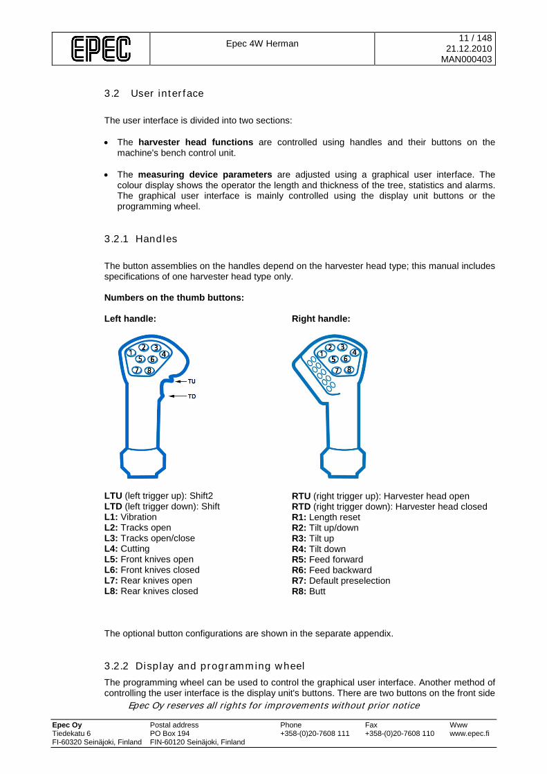
3.2.1 Handles The button assemblies on the handles depend on the harvester head type; this manual includes specifications of one harvester head type only. Numbers on the thumb buttons: Left handle:
LTU (left trigger up): Shift2 LTD (left trigger down): Shift L1: Vibration L2: Tracks open L3: Tracks open/close L4: Cutting L5: Front knives open L6: Front knives closed L7: Rear knives open L8: Rear knives closed
Right handle:
RTU (right trigger up): Harvester head open RTD (right trigger down): Harvester head closed R1: Length reset R2: Tilt up/down R3: Tilt up R4: Tilt down R5: Feed forward R6: Feed backward R7: Default preselection R8: Butt
The optional button configurations are shown in the separate appendix.
3.2.2 Display and programming wheel The programming wheel can be used to control the graphical user interface. Another method of controlling the user interface is the display unit's buttons. There are two buttons on the front side

Epec 4W Herman
12 / 148 21.12.2010
MAN000403
Epec Oy reserves all rights for improvements without prior notice Epec Oy Postal address Phone Fax Www Tiedekatu 6 PO Box 194 +358-(0)20-7608 111 +358-(0)20-7608 110 www.epec.fi FI-60320 Seinäjoki, Finland FIN-60120 Seinäjoki, Finland
of the programming wheel: Cancel (red) and OK (green). It is possible to navigate through the user interface screens and the different fields of the screens by rotating the programming wheel. There are five buttons used to control the graphical user interface at the bottom edge of the display control unit. These buttons are: Back, Previous, OK, Next and Info. The graphical user interface is controlled using the buttons at the bottom of the display unit or the programming wheel. The main tasks of the display unit are:
• Offering information • Calculate and save work area production statistics • Enabling system adjustments • Transferring information to printer • Copying information into a file when necessary • Maintaining software versions of control units connected to the system
For more specific descriptions of the programming wheel and display unit buttons and control features, see Chapter 5.1 Display buttons and programming wheel.
Epec 4W Herman
13 / 148 21.12.2010
MAN000403
Epec Oy reserves all rights for improvements without prior notice Epec Oy Postal address Phone Fax Www Tiedekatu 6 PO Box 194 +358-(0)20-7608 111 +358-(0)20-7608 110 www.epec.fi FI-60320 Seinäjoki, Finland FIN-60120 Seinäjoki, Finland
4 CONTROLLING FUNCTIONS The harvester head functions presented in this chapter are mainly controlled with the handles and the programming wheel.
4.1 Safety lock and safety switch The purpose of the safety lock is to disable the harvester head controls during startup, as well as when the operator is not in the cabin. The safety switch is usually located on the operator seat, the cabin door or, in the case of an excavator-based system, in the so-called safety mode switch. The safety lock will be activated, i.e. locked, when: • the system is started up • the safety switch is triggered • a chain replacement sequence ends • after default/restoring factory parameters When the safety lock is engaged, there is a safety lock symbol on the display unit's main menu and access to the handling screen is not allowed. The harvester head control features are also disabled. The measuring device locking can be disabled by deactivating the safety switch and opening the safety lock using the button command Shift + Harvester head closed. The display unit will transfer directly from the menu to the handling screen when you press Shift + Harvester head closed. When you press the Shift button, the notification ”Press the harvester head closed button” will be displayed. Only the Shift + Harvester head closed buttons can be pressed when the safety lock is being deactivated. If any other buttons are pressed, the safety lock will not be deactivated.
4.2 Controlling the harvester head functions
The opening movement of the actuator is always dominant. If you try to simultaneously close and open the actuator, the open control will be dominant and thus the actuator will open. This applies to all harvester head functions.
Controlling the eco harvester head is slightly different then controlling the so called normal harvester head. Chapter 4.2.1 describes how the eco harvester head functions on a general level. In addition, other chapters will inform how and if the eco harvester head differs from normal functions. 4.2.1 Controlling eco harvester head The eco harvester head refers to the harvester head type, which is designed to be used for processing logs and loading. The eco harvester head differs from the so called normal harvester head basically because of the noticably greater maximum open position, which makes it possible to load several logs simultaneousely. The eco harvester head control differs from the normal harvester head because the functions are divided into two different modes: processing and loading. The mode can be changed using the button combination, Shift+Harvester head open. The measuring device must be in loading mode and the handling screen must show the loading symbol.
Epec 4W Herman
14 / 148 21.12.2010
MAN000403
Epec Oy reserves all rights for improvements without prior notice Epec Oy Postal address Phone Fax Www Tiedekatu 6 PO Box 194 +358-(0)20-7608 111 +358-(0)20-7608 110 www.epec.fi FI-60320 Seinäjoki, Finland FIN-60120 Seinäjoki, Finland
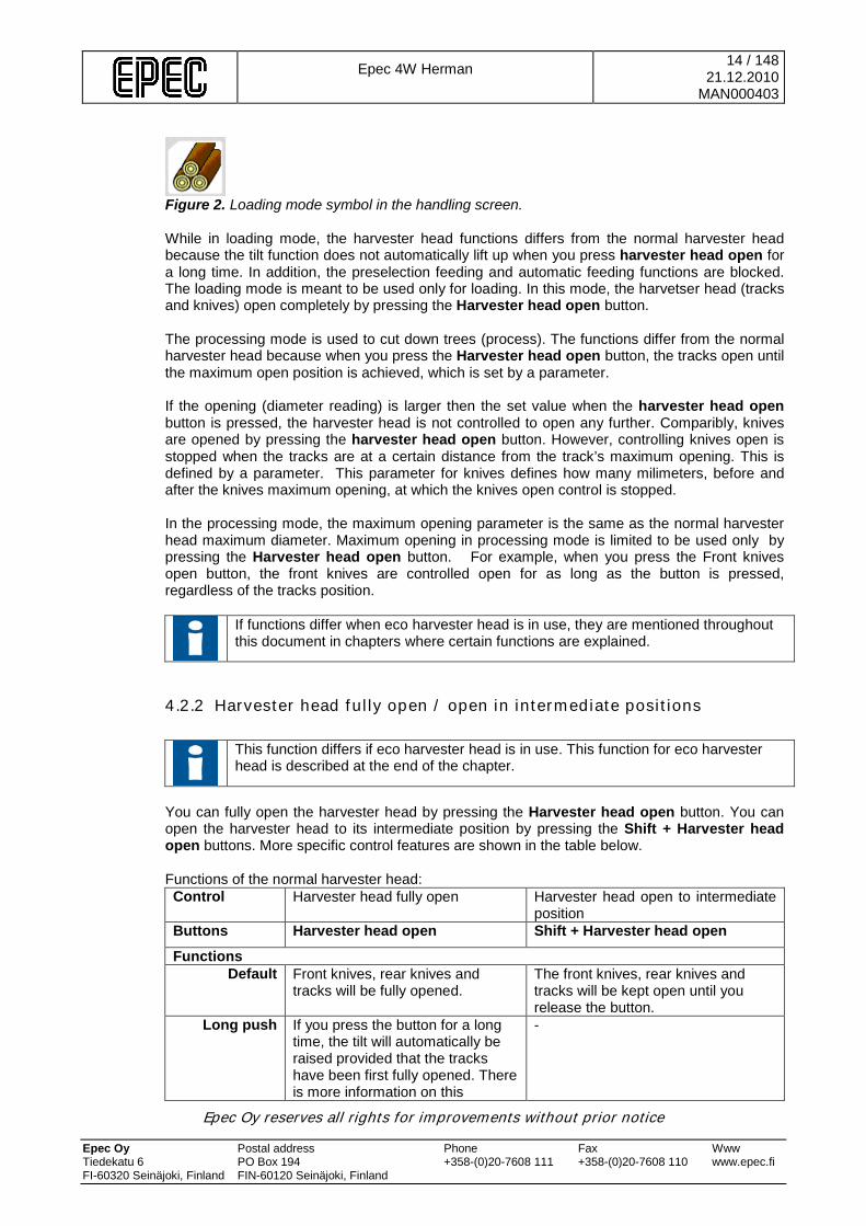
Figure 2. Loading mode symbol in the handling screen. While in loading mode, the harvester head functions differs from the normal harvester head because the tilt function does not automatically lift up when you press harvester head open for a long time. In addition, the preselection feeding and automatic feeding functions are blocked. The loading mode is meant to be used only for loading. In this mode, the harvetser head (tracks and knives) open completely by pressing the Harvester head open button. The processing mode is used to cut down trees (process). The functions differ from the normal harvester head because when you press the Harvester head open button, the tracks open until the maximum open position is achieved, which is set by a parameter. If the opening (diameter reading) is larger then the set value when the harvester head open button is pressed, the harvester head is not controlled to open any further. Comparibly, knives are opened by pressing the harvester head open button. However, controlling knives open is stopped when the tracks are at a certain distance from the track’s maximum opening. This is defined by a parameter. This parameter for knives defines how many milimeters, before and after the knives maximum opening, at which the knives open control is stopped. In the processing mode, the maximum opening parameter is the same as the normal harvester head maximum diameter. Maximum opening in processing mode is limited to be used only by pressing the Harvester head open button. For example, when you press the Front knives open button, the front knives are controlled open for as long as the button is pressed, regardless of the tracks position.
If functions differ when eco harvester head is in use, they are mentioned throughout this document in chapters where certain functions are explained.
4.2.2 Harvester head fully open / open in intermediate positions
This function differs if eco harvester head is in use. This function for eco harvester head is described at the end of the chapter.
You can fully open the harvester head by pressing the Harvester head open button. You can open the harvester head to its intermediate position by pressing the Shift + Harvester head open buttons. More specific control features are shown in the table below. Functions of the normal harvester head: Control Harvester head fully open Harvester head open to intermediate
position Buttons Harvester head open Shift + Harvester head open
Functions Default Front knives, rear knives and
tracks will be fully opened.
The front knives, rear knives and tracks will be kept open until you release the button.
Long push If you press the button for a long time, the tilt will automatically be raised provided that the tracks have been first fully opened. There is more information on this
-
Epec 4W Herman
15 / 148 21.12.2010
MAN000403
Epec Oy reserves all rights for improvements without prior notice Epec Oy Postal address Phone Fax Www Tiedekatu 6 PO Box 194 +358-(0)20-7608 111 +358-(0)20-7608 110 www.epec.fi FI-60320 Seinäjoki, Finland FIN-60120 Seinäjoki, Finland
function in Chapter 4.2.4 Tilt up/down.
During feeding If you press the button while feeding wood, the front and rear knives will be opened until you release the button. When you release the button, the harvester head will automatically be closed if the feed function is still active.
Function if eco harvester head is in use: In the loading state, the harvester head is controlled completely open by pressing the Harvester head open button. By pressing Shift+Harvester head open, the harvester head is controlled open to the intermediate position. In the processing state, the harvester head is not controlled open by pressing the Harvesterhead open button. Controlling open is stopped when the tracks opened to the parameter defined diameter. More accurate specifications for control are described in the following table: Control: Harvester head open Harvester head open to
intermediate position Buttons Harvester head open Shift + Harvester head open
Processing state: Default: Tracks are controlled open until
the parameter defined maximum opening is reached in the processing state. Knives are controlled open until they have opened to the parameter defined position.
Knives and tracks are controlled open as long as the button is pressed, if the the track’s opening is smaller then the specified maximum opening in the processing state.
Long push: If you press the button down for a long time, the tilt will automatically be raised. This is described further in chapter 4.2.4 Tilt up/down.
-
During feeding: If you press the button while feeding wood, the front and rear knives will be opened until you release the button. When you release the button, the harvester head will automatically be closed if the feed function is still active.
Loading state: Default: Front knives, rear knives and
tracks will be fully opened.
The front knives, rear knives and tracks will be kept open until you release the button.
Long push: Tilt is not raised automatically
-
During feeding: If you press the button while feeding wood, the front and rear knives will be opened until you release the button. When you release the button, the harvester head will automatically be closed if the feed function is still active.
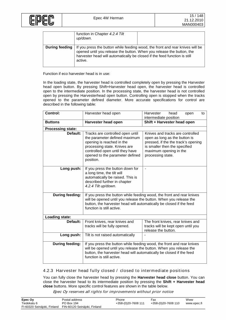
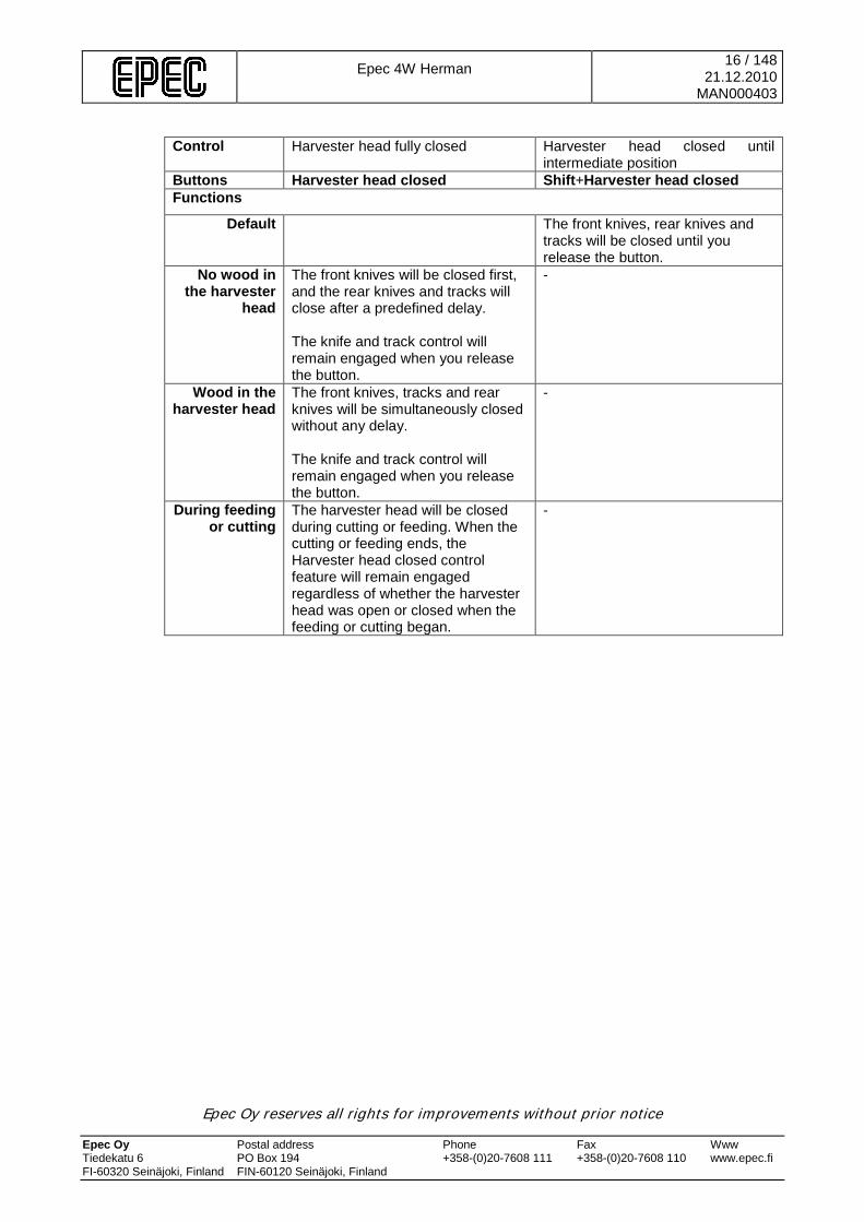
4.2.3 Harvester head fully closed / closed to intermediate positions You can fully close the harvester head by pressing the Harvester head close button. You can close the harvester head to its intermediate position by pressing the Shift + Harvester head close buttons. More specific control features are shown in the table below.
Epec 4W Herman
16 / 148 21.12.2010
MAN000403
Epec Oy reserves all rights for improvements without prior notice Epec Oy Postal address Phone Fax Www Tiedekatu 6 PO Box 194 +358-(0)20-7608 111 +358-(0)20-7608 110 www.epec.fi FI-60320 Seinäjoki, Finland FIN-60120 Seinäjoki, Finland
Control Harvester head fully closed Harvester head closed until
intermediate position Buttons Harvester head closed Shift+Harvester head closed Functions
Default The front knives, rear knives and tracks will be closed until you release the button.
No wood in the harvester
head
The front knives will be closed first, and the rear knives and tracks will close after a predefined delay. The knife and track control will remain engaged when you release the button.
-
Wood in the harvester head
The front knives, tracks and rear knives will be simultaneously closed without any delay. The knife and track control will remain engaged when you release the button.
-
During feeding or cutting
The harvester head will be closed during cutting or feeding. When the cutting or feeding ends, the Harvester head closed control feature will remain engaged regardless of whether the harvester head was open or closed when the feeding or cutting began.
-
Epec 4W Herman
17 / 148 21.12.2010
MAN000403
Epec Oy reserves all rights for improvements without prior notice Epec Oy Postal address Phone Fax Www Tiedekatu 6 PO Box 194 +358-(0)20-7608 111 +358-(0)20-7608 110 www.epec.fi FI-60320 Seinäjoki, Finland FIN-60120 Seinäjoki, Finland
4.2.4 Tilt up/down and tilt floating
This function differs if eco harvester head is in use. This function for eco harvester head is described at the end of the chapter.
You can move the tilt up or down using the Tilt up and Tilt down buttons. The Tilt up/down buttons move the tilt in the opposite direction from where it was when the control was started, i.e. these buttons allow moving the tilt back and forth. More specific control features are shown in the table below. Control Harvester head up Harvester head down Tilt up/down Buttons Harvester head up Harvester head down Tilt up/down Functions
Tilt in the upper position
The tilt is controlled upwards (into the upright position).
When the tilt is in the upright position, it will be moved downwards (to the horizontal position) for as long as you press the button.
When the tilt is in the upright position, it will be moved downwards (to the horizontal position) for as long as you press the button.
Tilt floating or tilt in the lower
position
The tilt is controlled upwards (into the upright position).
When the tilt is in the upright position, it will be moved downwards (to the horizontal position) for as long as you press the button.
The tilt is controlled upwards (into the upright position).
Additional information
If you press and hold the Harvester head button, the harvester head will be first fully opened and then lifted up. When you release the button, the Harvester head up control feature will remain engaged. Thus, the harvester head is in the felling mode (see Felling mode). If you do not want the harvester head to automatically rise, you can disable this function using a parameter.
When you release the button, the tilt will remain in uncontrolled mode (floating).
If the tilt is moved upwards, the up control will remain engaged. If the tilt is moved downwards, the control will end when you release the button.
The tilt is in the floating mode unless it is • in the upright position • in the horizontal position The tilt will automatically be transferred to the floating mode during felling. For more information on this function, please see Chapter 4.7.2.2 Releasing tilt during felling. You can manually release the tilt into the floating mode when it is up by briefly pressing the Harvester head down button. Function if eco harvester head is in use:
Epec 4W Herman
18 / 148 21.12.2010
MAN000403
Epec Oy reserves all rights for improvements without prior notice Epec Oy Postal address Phone Fax Www Tiedekatu 6 PO Box 194 +358-(0)20-7608 111 +358-(0)20-7608 110 www.epec.fi FI-60320 Seinäjoki, Finland FIN-60120 Seinäjoki, Finland
While in loading state, pressing the Harvester head open button for a long time will not lift automatically to the upright position.
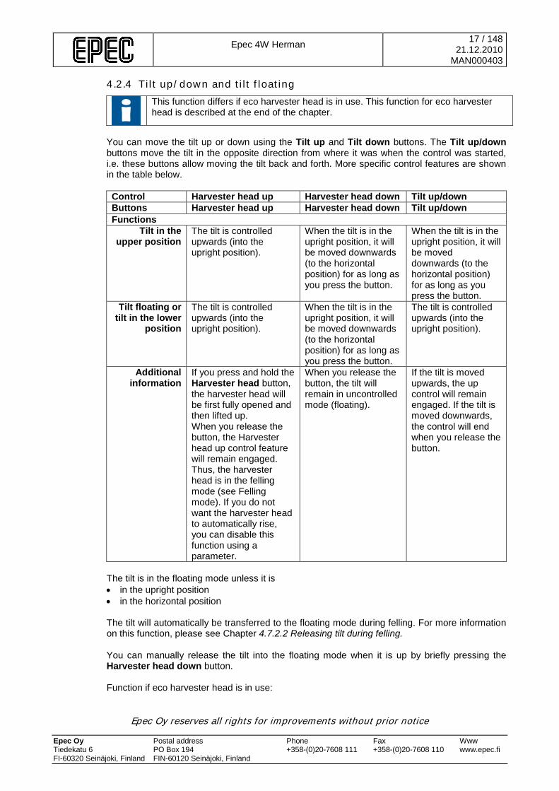
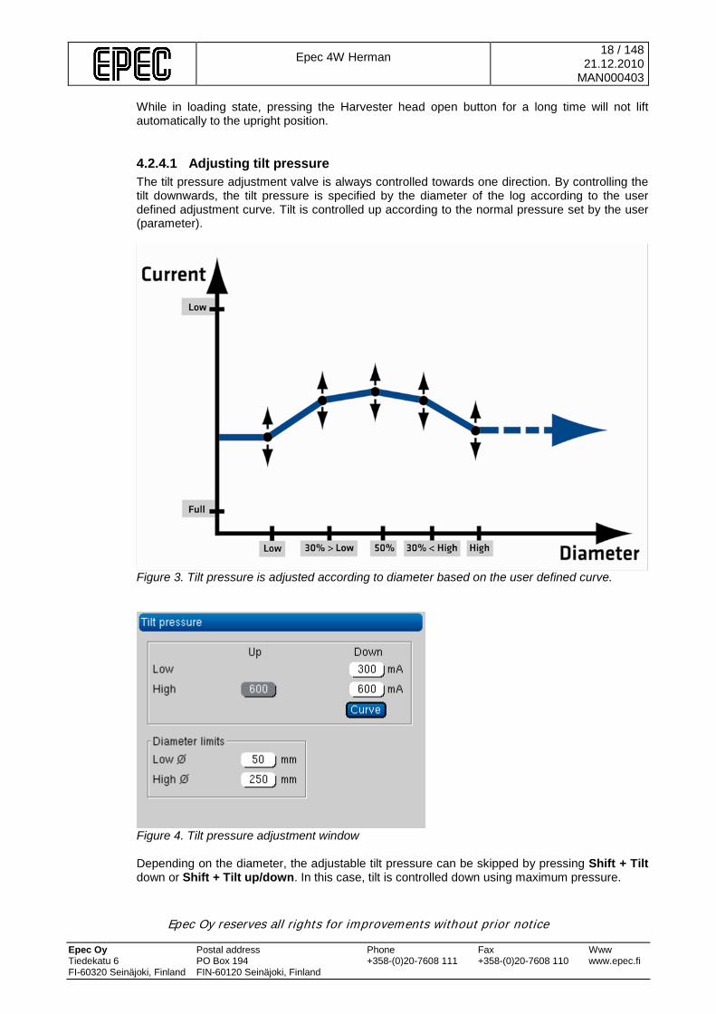
4.2.4.1 Adjusting tilt pressure The tilt pressure adjustment valve is always controlled towards one direction. By controlling the tilt downwards, the tilt pressure is specified by the diameter of the log according to the user defined adjustment curve. Tilt is controlled up according to the normal pressure set by the user (parameter).
Figure 3. Tilt pressure is adjusted according to diameter based on the user defined curve.
Figure 4. Tilt pressure adjustment window Depending on the diameter, the adjustable tilt pressure can be skipped by pressing Shift + Tilt down or Shift + Tilt up/down. In this case, tilt is controlled down using maximum pressure.
Epec 4W Herman
19 / 148 21.12.2010
MAN000403
Epec Oy reserves all rights for improvements without prior notice Epec Oy Postal address Phone Fax Www Tiedekatu 6 PO Box 194 +358-(0)20-7608 111 +358-(0)20-7608 110 www.epec.fi FI-60320 Seinäjoki, Finland FIN-60120 Seinäjoki, Finland
Tilt pressure adjustment function can be controlled off using a parameter as long as the harvester head is not using the tilt pressure adjustment valve.
4.3 Controlling delimbing knives
The opening movement of the actuator is always dominant. If you try to simultaneously close and open the actuator, the open control will be dominant and thus the actuator will open. This applies to all harvester head functions.
4.3.1 Front knives fully open / open to intermediate positions
This function differs if eco harvester head is in use. This function for eco harvester head is described at the end of the chapter.
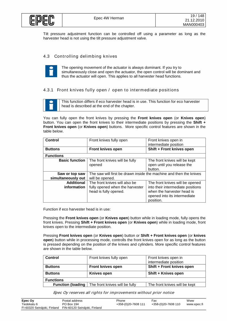
You can fully open the front knives by pressing the Front knives open (or Knives open) button. You can open the front knives to their intermediate positions by pressing the Shift + Front knives open (or Knives open) buttons. More specific control features are shown in the table below. Control Front knives fully open Front knives open in
intermediate position Buttons Front knives open Shift + Front knives open
Functions Basic function The front knives will be fully
opened The front knives will be kept open until you release the button.
Saw or top saw simultaneously out
The saw will first be drawn inside the machine and then the knives will be opened.
Additional information
The front knives will also be fully opened when the harvester head is fully opened.
The front knives will be opened into their intermediate positions when the harvester head is opened into its intermediate position.
Function if eco harvester head is in use: Pressing the Front knives open (or Knives open) button while in loading mode, fully opens the front knives. Pressing Shift + Front knives open (or Knives open) while in loading mode, front knives open to the intermediate position. Pressing Front knives open (or Knives open) button or Shift + Front knives open (or knives open) button while in processing mode, controlls the front knives open for as long as the button is pressed depending on the position of the knives and cylinders. More specific control features are shown in the table below. Control Front knives fully open Front knives open in
intermediate position Buttons Front knives open Shift + Front knives open
Buttons Knives open Shift + Knives open
Functions Function (loading The front knives will be fully The front knives will be kept

Epec 4W Herman
20 / 148 21.12.2010
MAN000403
Epec Oy reserves all rights for improvements without prior notice Epec Oy Postal address Phone Fax Www Tiedekatu 6 PO Box 194 +358-(0)20-7608 111 +358-(0)20-7608 110 www.epec.fi FI-60320 Seinäjoki, Finland FIN-60120 Seinäjoki, Finland
mode) opened open until you release the button.
Function (processing mode)
The front knives will be kept open until you release the button.
The front knives will be kept open until you release the button.
Saw or top saw simultaneously out
The saw will first be drawn inside the machine and then the knives will be opened.
4.3.2 Front knives fully closed / closed until the intermediate positions You can fully close the front knives by pressing the Front knives closed (or Knives closed) button. The knives will be closed until you release the Shift + Front knives closed (or Shift + Knives closed) buttons. More specific control features are shown in the table below. Control Front knives fully closed Front knives closed until
intermediate positions Buttons Press: Front knives closed
Press: Shift + Front knives closed
Functions Basic function The front knives will be fully
closed. The control will remain engaged even if the button is released.
The front knives will be kept closed until you release the button.
When feeding and cutting
The front knives will be fully closed. The control will remain engaged when the feeding and cutting has ended.
Additional information
The front knives will also be fully closed when the harvester head is fully closed.
The front knives will be closed to their intermediate positions when the harvester head is closed to its intermediate position.
4.3.3 Rear knives fully open / open to intermediate positions
This function differs if eco harvester head is in use. This function for eco harvester head is described at the end of the chapter.
You can fully open the rear knives by pressing the Rear knives open (or Knives open) button. The rear knives will be closed as long as you press and hold the Shift + Rear knives closed (or Shift + Knives closed) buttons. More specific control features are shown in the table below. Control Rear knives fully open Rear knives open until the
intermediate positions Buttons Press: Rear knives open
Press: Shift + Rear knives open
Functions Basic function The rear knives will be fully
opened.
The rear knives will be kept open until you release the button
When the saw or top saw is
simultaneously out The saw will first be drawn inside the machine and the knives will be opened then.
When the length measurement
becomes negative
The rear knives will be automatically fully opened. For more information, please see Chapter 4.3.6 Automatic rear
Epec 4W Herman
21 / 148 21.12.2010
MAN000403
Epec Oy reserves all rights for improvements without prior notice Epec Oy Postal address Phone Fax Www Tiedekatu 6 PO Box 194 +358-(0)20-7608 111 +358-(0)20-7608 110 www.epec.fi FI-60320 Seinäjoki, Finland FIN-60120 Seinäjoki, Finland
knives' control with negative length measurement.
Additional information
The rear knives will also be fully opened when the harvester head is fully opened.
The rear knives will be opened into their intermediate positions when the harvester head is opened into its intermediate position.
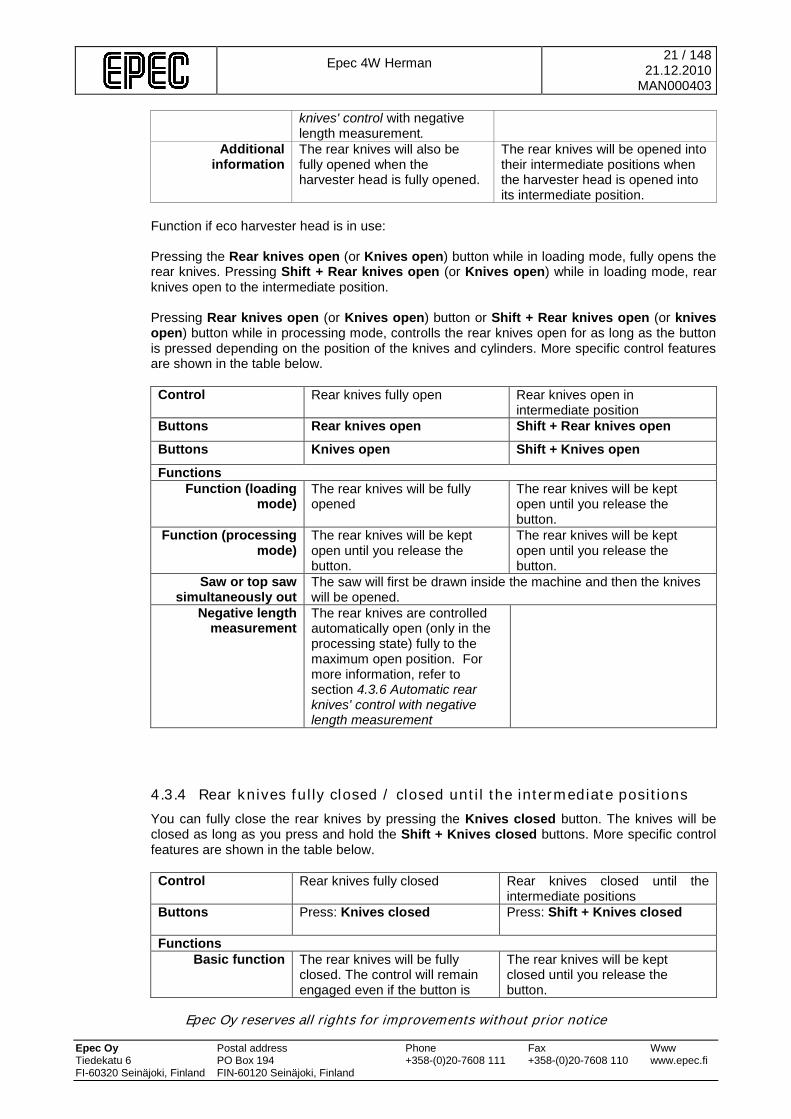
Function if eco harvester head is in use: Pressing the Rear knives open (or Knives open) button while in loading mode, fully opens the rear knives. Pressing Shift + Rear knives open (or Knives open) while in loading mode, rear knives open to the intermediate position. Pressing Rear knives open (or Knives open) button or Shift + Rear knives open (or knives open) button while in processing mode, controlls the rear knives open for as long as the button is pressed depending on the position of the knives and cylinders. More specific control features are shown in the table below. Control Rear knives fully open Rear knives open in
intermediate position Buttons Rear knives open Shift + Rear knives open
Buttons Knives open Shift + Knives open
Functions Function (loading
mode) The rear knives will be fully opened
The rear knives will be kept open until you release the button.
Function (processing mode)
The rear knives will be kept open until you release the button.
The rear knives will be kept open until you release the button.
Saw or top saw simultaneously out
The saw will first be drawn inside the machine and then the knives will be opened.
Negative length measurement
The rear knives are controlled automatically open (only in the processing state) fully to the maximum open position. For more information, refer to section 4.3.6 Automatic rear knives' control with negative length measurement
4.3.4 Rear knives fully closed / closed until the intermediate positions You can fully close the rear knives by pressing the Knives closed button. The knives will be closed as long as you press and hold the Shift + Knives closed buttons. More specific control features are shown in the table below. Control Rear knives fully closed Rear knives closed until the
intermediate positions Buttons Press: Knives closed
Press: Shift + Knives closed
Functions Basic function The rear knives will be fully
closed. The control will remain engaged even if the button is
The rear knives will be kept closed until you release the button.

Epec 4W Herman
22 / 148 21.12.2010
MAN000403
Epec Oy reserves all rights for improvements without prior notice Epec Oy Postal address Phone Fax Www Tiedekatu 6 PO Box 194 +358-(0)20-7608 111 +358-(0)20-7608 110 www.epec.fi FI-60320 Seinäjoki, Finland FIN-60120 Seinäjoki, Finland
released.
When feeding and cutting
The rear knives will be fully closed when feeding and cutting. The control will remain engaged when the feeding and cutting has ended. Automatic closing of the rear knives when feeding and cutting after automatic opening of the rear knives will be prevented by the system. For more information on this function, please see Chapter 4.3.6 Automatic rear knives' control with negative length measurement.
Additional information
The rear knives will also be fully closed when the harvester head is fully closed.
The rear knives will be closed to their intermediate positions when the harvester head is closed to its intermediate position.
4.3.5 Knifes vibration The harvester knives can be vibrated using the automatic vibration feature and/or extra vibration feature: • The automatic vibration feature causes the front knives, the rear knives or both front and rear
knives to vibrate, either by means of an opening pulse or by means of directional valve vibration, depending on what selections you have made.
• The extra vibration feature means that both knives are vibrated with a longer opening time. The extra vibration will be engaged as long as you press the button, regardless of whether or not automatic vibration is in use.
You can activate the extra vibration feature by pressing the Knife vibration button. You can activate the automatic vibration feature by pressing the Shift + Knife vibration buttons. More specific control features are shown in the table below.
Control Activating extra vibration Activating automatic vibration Buttons Knife vibration Shift + Knife vibration
Functions Basic function The vibration of both knives will
be engaged with the longer opening time until you release the button, regardless of whether or not automatic vibration is in use.
The selected vibration features are available if the knives have been closed.
Additional information
The extra vibration feature always overrides the automatic vibration feature and its conditions. If there are deformities in the tree log, you can lighten the grip of the knives with the extra vibration feature until you have crossed the difficult section of
The vibration features are not available during slow automatic feed and/or when search pulse is engaged. This parameter also allows setting a diameter limit above which the vibration features are not available.

Epec 4W Herman
23 / 148 21.12.2010
MAN000403
Epec Oy reserves all rights for improvements without prior notice Epec Oy Postal address Phone Fax Www Tiedekatu 6 PO Box 194 +358-(0)20-7608 111 +358-(0)20-7608 110 www.epec.fi FI-60320 Seinäjoki, Finland FIN-60120 Seinäjoki, Finland
the log. When knife vibration is engaged, the knife vibration symbol is visible at the bottom edge of the handling screen:
Figure 5. The knife vibration symbol on the handling screen. Automatic vibration alternatives: • Knife opening pulse (Start pulse)
In order to facilitate the start of feeding, the knives will be issued a short start pulse when forwards or backwards feed is started and the knives are closed. This parameter adjusts the delay between the starting of the feed and the start pulse. The length of the start pulse and other settings are adjusted in the start pulse window (Settings Parameters Start pulse). If the directional valve vibration is also in use in addition to the start pulse, the vibration feature will not be activated until the knives have closed after the start pulse.
Figure 6. Start pulse adjustment screen The start pulse length is adjusted according to the log’s diameter between the value limits in the screen. The front knives and back knives have their own limit values (MinØ start and MaxØ start) for both feeding directions. MinØ start time uses MinØ as the diameter limit and
Epec 4W Herman
24 / 148 21.12.2010
MAN000403
Epec Oy reserves all rights for improvements without prior notice Epec Oy Postal address Phone Fax Www Tiedekatu 6 PO Box 194 +358-(0)20-7608 111 +358-(0)20-7608 110 www.epec.fi FI-60320 Seinäjoki, Finland FIN-60120 Seinäjoki, Finland
and logs with smaller diameters. MaxØ start time uses MaxØ as the diameter limit and for logs with larger diameters. The diameter must be must be between these limit values and the start time adjusts linearly between the Min and Max values depending on the diameter. With this function, you can also set the diameter value (OffØ) so that the pulse start is not used for logs with smaller diameters. Also, the additional vibration percentage can be adjusted in this screen. The additional vibration percentage and diameter limits are joint with the knives vibration function, so when these vlaues are changed, the knives vibration function also changes.
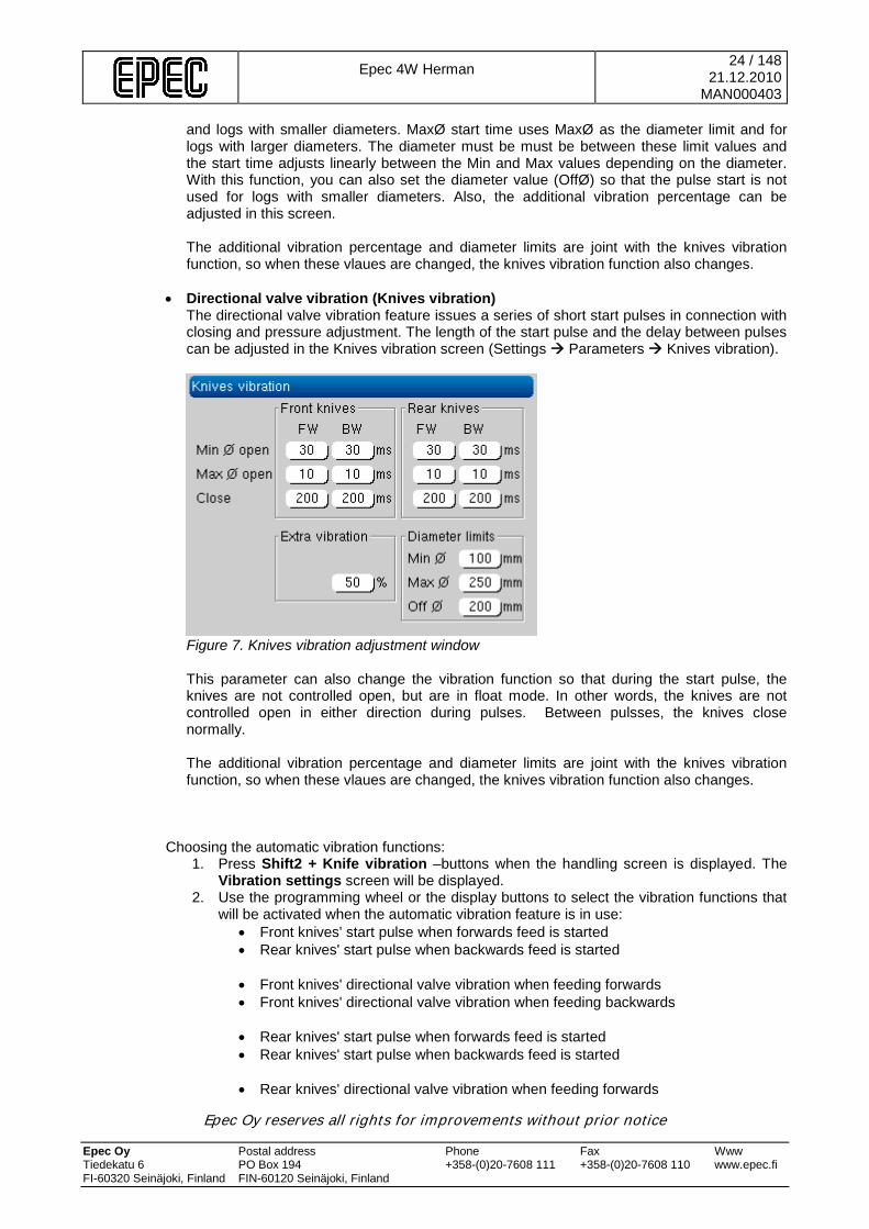
• Directional valve vibration (Knives vibration) The directional valve vibration feature issues a series of short start pulses in connection with closing and pressure adjustment. The length of the start pulse and the delay between pulses can be adjusted in the Knives vibration screen (Settings Parameters Knives vibration).
Figure 7. Knives vibration adjustment window This parameter can also change the vibration function so that during the start pulse, the knives are not controlled open, but are in float mode. In other words, the knives are not controlled open in either direction during pulses. Between pulsses, the knives close normally. The additional vibration percentage and diameter limits are joint with the knives vibration function, so when these vlaues are changed, the knives vibration function also changes.
Choosing the automatic vibration functions:
1. Press Shift2 + Knife vibration –buttons when the handling screen is displayed. The Vibration settings screen will be displayed.
2. Use the programming wheel or the display buttons to select the vibration functions that will be activated when the automatic vibration feature is in use:
• Front knives' start pulse when forwards feed is started • Rear knives' start pulse when backwards feed is started
• Front knives' directional valve vibration when feeding forwards • Front knives' directional valve vibration when feeding backwards
• Rear knives' start pulse when forwards feed is started • Rear knives' start pulse when backwards feed is started
• Rear knives' directional valve vibration when feeding forwards
Epec 4W Herman
25 / 148 21.12.2010
MAN000403
Epec Oy reserves all rights for improvements without prior notice Epec Oy Postal address Phone Fax Www Tiedekatu 6 PO Box 194 +358-(0)20-7608 111 +358-(0)20-7608 110 www.epec.fi FI-60320 Seinäjoki, Finland FIN-60120 Seinäjoki, Finland
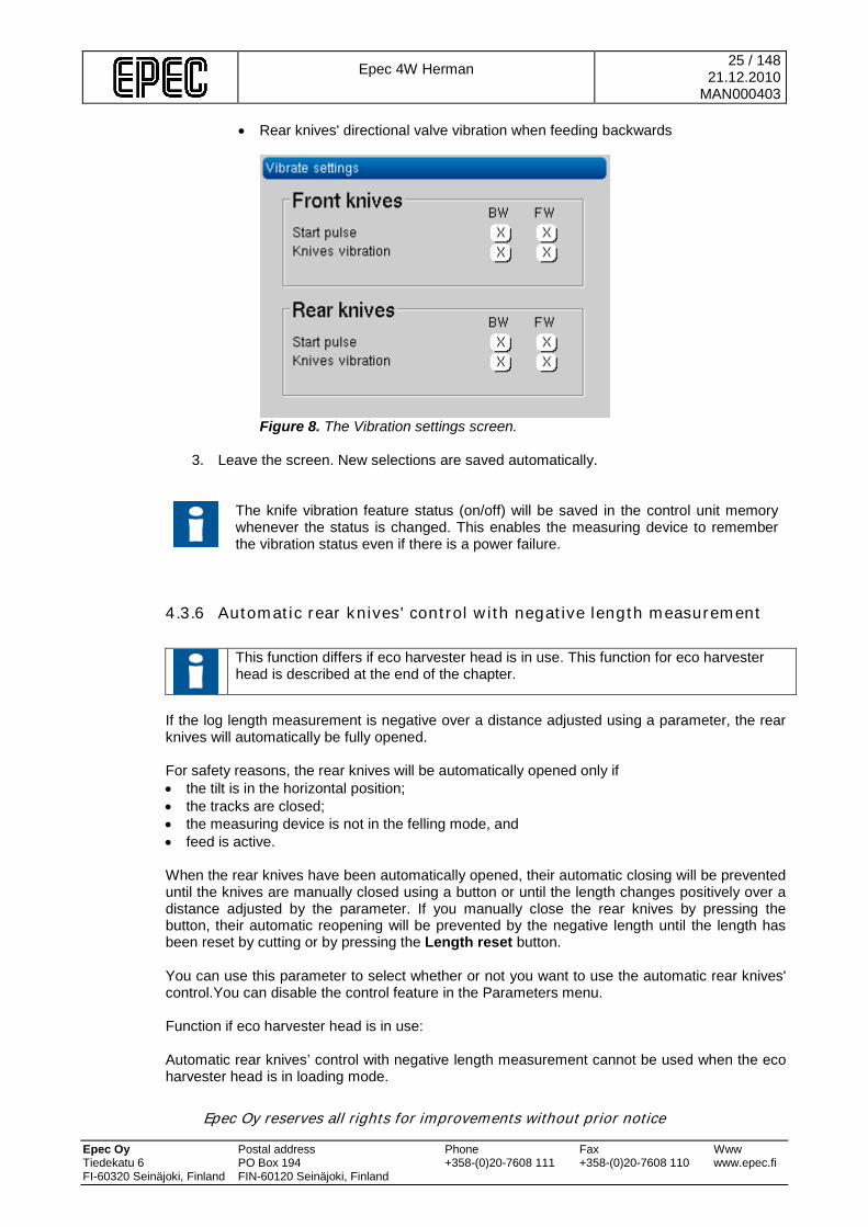
• Rear knives' directional valve vibration when feeding backwards
Figure 8. The Vibration settings screen.
3. Leave the screen. New selections are saved automatically.
The knife vibration feature status (on/off) will be saved in the control unit memory whenever the status is changed. This enables the measuring device to remember the vibration status even if there is a power failure.
4.3.6 Automatic rear knives' control with negative length measurement
This function differs if eco harvester head is in use. This function for eco harvester head is described at the end of the chapter.
If the log length measurement is negative over a distance adjusted using a parameter, the rear knives will automatically be fully opened. For safety reasons, the rear knives will be automatically opened only if • the tilt is in the horizontal position; • the tracks are closed; • the measuring device is not in the felling mode, and • feed is active. When the rear knives have been automatically opened, their automatic closing will be prevented until the knives are manually closed using a button or until the length changes positively over a distance adjusted by the parameter. If you manually close the rear knives by pressing the button, their automatic reopening will be prevented by the negative length until the length has been reset by cutting or by pressing the Length reset button. You can use this parameter to select whether or not you want to use the automatic rear knives' control.You can disable the control feature in the Parameters menu. Function if eco harvester head is in use: Automatic rear knives’ control with negative length measurement cannot be used when the eco harvester head is in loading mode.
Epec 4W Herman
26 / 148 21.12.2010
MAN000403
Epec Oy reserves all rights for improvements without prior notice Epec Oy Postal address Phone Fax Www Tiedekatu 6 PO Box 194 +358-(0)20-7608 111 +358-(0)20-7608 110 www.epec.fi FI-60320 Seinäjoki, Finland FIN-60120 Seinäjoki, Finland
In processing mode, if the log measures negative over the paremeter set distance, the rear knives automatically open to the maximum position allowed in processing mode. Other then this, the function performs normally.
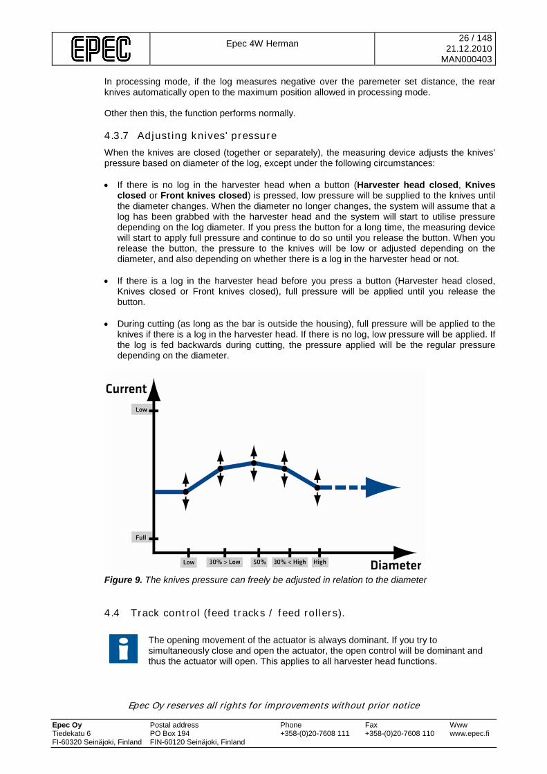
4.3.7 Adjusting knives' pressure When the knives are closed (together or separately), the measuring device adjusts the knives' pressure based on diameter of the log, except under the following circumstances: • If there is no log in the harvester head when a button (Harvester head closed, Knives
closed or Front knives closed) is pressed, low pressure will be supplied to the knives until the diameter changes. When the diameter no longer changes, the system will assume that a log has been grabbed with the harvester head and the system will start to utilise pressure depending on the log diameter. If you press the button for a long time, the measuring device will start to apply full pressure and continue to do so until you release the button. When you release the button, the pressure to the knives will be low or adjusted depending on the diameter, and also depending on whether there is a log in the harvester head or not.
• If there is a log in the harvester head before you press a button (Harvester head closed,
Knives closed or Front knives closed), full pressure will be applied until you release the button.
• During cutting (as long as the bar is outside the housing), full pressure will be applied to the
knives if there is a log in the harvester head. If there is no log, low pressure will be applied. If the log is fed backwards during cutting, the pressure applied will be the regular pressure depending on the diameter.
Figure 9. The knives pressure can freely be adjusted in relation to the diameter
4.4 Track control (feed tracks / feed rollers).
The opening movement of the actuator is always dominant. If you try to simultaneously close and open the actuator, the open control will be dominant and thus the actuator will open. This applies to all harvester head functions.
Epec 4W Herman
27 / 148 21.12.2010
MAN000403
Epec Oy reserves all rights for improvements without prior notice Epec Oy Postal address Phone Fax Www Tiedekatu 6 PO Box 194 +358-(0)20-7608 111 +358-(0)20-7608 110 www.epec.fi FI-60320 Seinäjoki, Finland FIN-60120 Seinäjoki, Finland
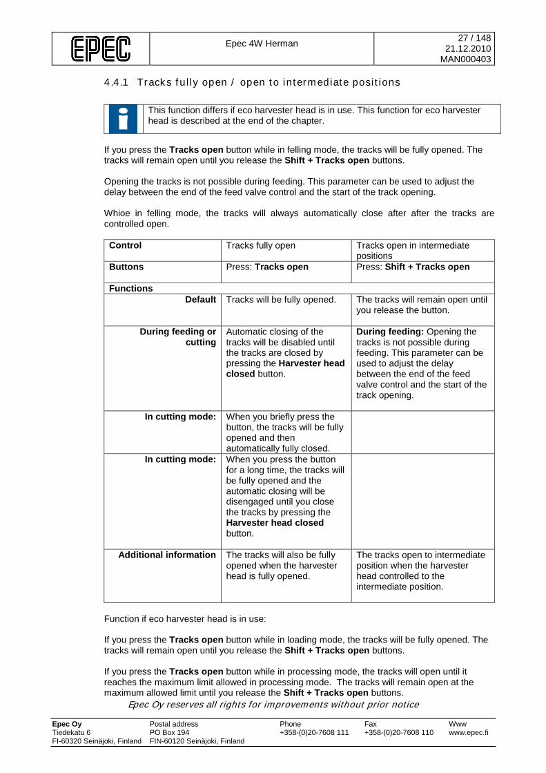
4.4.1 Tracks fully open / open to intermediate positions
This function differs if eco harvester head is in use. This function for eco harvester head is described at the end of the chapter.
If you press the Tracks open button while in felling mode, the tracks will be fully opened. The tracks will remain open until you release the Shift + Tracks open buttons.
Opening the tracks is not possible during feeding. This parameter can be used to adjust the delay between the end of the feed valve control and the start of the track opening. Whioe in felling mode, the tracks will always automatically close after after the tracks are controlled open. Control Tracks fully open Tracks open in intermediate
positions Buttons Press: Tracks open
Press: Shift + Tracks open
Functions Default Tracks will be fully opened.
The tracks will remain open until you release the button.
During feeding or cutting
Automatic closing of the tracks will be disabled until the tracks are closed by pressing the Harvester head closed button.
During feeding: Opening the tracks is not possible during feeding. This parameter can be used to adjust the delay between the end of the feed valve control and the start of the track opening.
In cutting mode: When you briefly press the button, the tracks will be fully opened and then automatically fully closed.
In cutting mode: When you press the button for a long time, the tracks will be fully opened and the automatic closing will be disengaged until you close the tracks by pressing the Harvester head closed button.
Additional information The tracks will also be fully opened when the harvester head is fully opened.
The tracks open to intermediate position when the harvester head controlled to the intermediate position.
Function if eco harvester head is in use: If you press the Tracks open button while in loading mode, the tracks will be fully opened. The tracks will remain open until you release the Shift + Tracks open buttons. If you press the Tracks open button while in processing mode, the tracks will open until it reaches the maximum limit allowed in processing mode. The tracks will remain open at the maximum allowed limit until you release the Shift + Tracks open buttons.

Epec 4W Herman
28 / 148 21.12.2010
MAN000403
Epec Oy reserves all rights for improvements without prior notice Epec Oy Postal address Phone Fax Www Tiedekatu 6 PO Box 194 +358-(0)20-7608 111 +358-(0)20-7608 110 www.epec.fi FI-60320 Seinäjoki, Finland FIN-60120 Seinäjoki, Finland
Opening the tracks is not possible during feeding. This parameter can be used to adjust the delay between the end of the feed valve control and the start of the track opening. When the eco harvester head is in use, the tracks’ automatic closing is not in use after starting. Control Tracks fully open Tracks open in intermediate
positions Buttons Press: Tracks open
Press: Shift + Tracks open
Functions During loading Tracks are controlled fully
open
Tracks are controlled open until the button is released
During processing Tracks are controlled open to the maximum limit allowed in the processing state.
Tracks are controlled open until the button is released, however, only to the maximum limit allowed in the processing state.
During feeding Tracks cannot be controlled open.
Tracks cannot be controlled open.
4.4.2 Tracks fully closed / closed until the intermediate positions The tracks will be fully closed when the harvester head is fully closed or you have pressed the Tracks close. The tracks will be closed to their intermediate positions when the harvester head is closed to its intermediate position or as long as the Shift + Tracks open buttons is pressed. Control Tracks fully closed Tracks closed to the
intermediate positions Buttons Press: Tracks close
Press: Shift + Tracks close
Functions Default Tracks will be fully closed.
The tracks will controlled to close as long as the buttons is pressed.
During feeding or cutting
The tracks will be automatically fully closed during cutting and feeding if the automatic track control has not been disengaged. The control will remain engaged when the cutting and feeding ends.
-
Additional information
The tracks will be fully closed when the harvester head is fully closed.
The tracks will be closed to their intermediate positions when the harvester head is closed to its intermediate position.

Epec 4W Herman
29 / 148 21.12.2010
MAN000403
Epec Oy reserves all rights for improvements without prior notice Epec Oy Postal address Phone Fax Www Tiedekatu 6 PO Box 194 +358-(0)20-7608 111 +358-(0)20-7608 110 www.epec.fi FI-60320 Seinäjoki, Finland FIN-60120 Seinäjoki, Finland
4.4.3 Adjusting track pressure When the tracks are being closed, their pressure will be adjusted based on the log diameter.
Figure 10. The track pressure can freely be adjusted in relation to the diameter
4.5 Rotator and extension (jib) control The measuring device supports optional methods for controlling the rotator. The rotator control method can be selected during the system installation from the following options:
1. Rotator is not controlled through the measuring device. 2. Rotator is controlled using the handles’ buttons
3. Rotator is controlled with the help of the handle. The right handle’s x direction
potentiometer signal (0...5V) is used to control the rotator. 4. Rotator is controlled with the help of the handle and pressure sensor. When, for
example, using an excavator as a base machine, pressure sensors can be connected to the bucket cylinder’s pre-pressure line , and the rotator can be controlled based on the sensor’s signal (0...5V). Both directions require their own sensors.
If the base machine is an excavator, it is usually required to use a so called boom extension (jib) , and this requires that the bucket cylinder must also be controlled. In this case, a selection valve can be connected to the measuring device, which can be used to select controlling of either the hydraulic rotator or the bucket cylinder. The section valve’s position can be changed using the handle buttons. Using a parameter, the control of either the rotator or the bucket cylinder can be set as the default when the measuring device is booted. If bucket cylinder control is selected, the bucket cylinder control symbol appears in the handling window.
Epec 4W Herman
30 / 148 21.12.2010
MAN000403
Epec Oy reserves all rights for improvements without prior notice Epec Oy Postal address Phone Fax Www Tiedekatu 6 PO Box 194 +358-(0)20-7608 111 +358-(0)20-7608 110 www.epec.fi FI-60320 Seinäjoki, Finland FIN-60120 Seinäjoki, Finland
Figure 11. Bucket cylinder control symbol..
The measuring device supports On/off type and current controlled proportional control valves for the rotator. The valve type is selected during system installation.
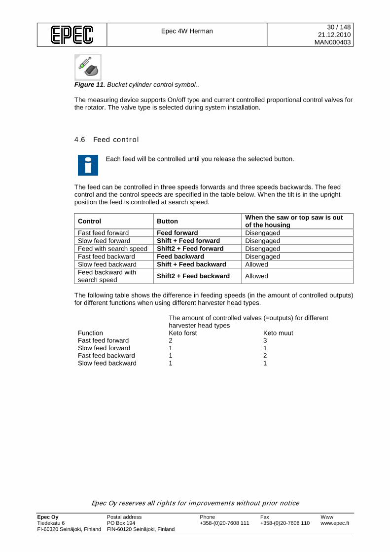
4.6 Feed control
Each feed will be controlled until you release the selected button.
The feed can be controlled in three speeds forwards and three speeds backwards. The feed control and the control speeds are specified in the table below. When the tilt is in the upright position the feed is controlled at search speed.
Control Button When the saw or top saw is out of the housing
Fast feed forward Feed forward Disengaged Slow feed forward Shift + Feed forward Disengaged Feed with search speed Shift2 + Feed forward Disengaged Fast feed backward Feed backward Disengaged Slow feed backward Shift + Feed backward Allowed Feed backward with search speed Shift2 + Feed backward Allowed
The following table shows the difference in feeding speeds (in the amount of controlled outputs) for different functions when using different harvester head types. The amount of controlled valves (=outputs) for different
harvester head types Function Keto forst Keto muut Fast feed forward 2 3 Slow feed forward 1 1 Fast feed backward 1 2 Slow feed backward 1 1

Epec 4W Herman
31 / 148 21.12.2010
MAN000403
Epec Oy reserves all rights for improvements without prior notice Epec Oy Postal address Phone Fax Www Tiedekatu 6 PO Box 194 +358-(0)20-7608 111 +358-(0)20-7608 110 www.epec.fi FI-60320 Seinäjoki, Finland FIN-60120 Seinäjoki, Finland
4.6.1 Feed modes You can select the feed mode by the three alternative by parameter (manual, preselection and automatic feed). The feed modes are specified in the tables below. Manual feed mode
Function/ Control
• The feed is manually controlled forwards or backwards using the buttons.
• After felling, you will manually control the system up until the length selected in the preselection and then cut the log.
• Pressing the preselection will not activate feed.
Using automatic functions
None of the following automatic functions are in use: • automatic cut-to-length • slipping prevention • slipping identification • pre-delimbing • butt end delimbing • preliminary cutting
Preselection feed mode
Function/ Control
• When the preselection has been selected, the measuring device will automatically control the system until the selected length, after which the operator will cut the log.
• You can also activate preliminary cutting, in which case the log will automatically be cut when the desired length has been reached.
• In the preselection feed mode, the feed will be activated when you press the preselection button.
Using automatic functions
All automatic functions are available.
Automatic feed mode
Function/ Control
• Similar to the preselection feed mode with the exception that the automatic control to length also takes place after cutting based on the same preselection.
• If you want to stop the automatic control to length after cutting the log in order to change the selected preselection, for example, you can do so in connection with cutting by pressing the Saw button for a long time or by pressing any other button that will stop the automatic functions.
• You can also use a parameter to define a diameter limit; when the diameter remains below the limit, the automatic feed will be disengaged.
Using automatic functions
All automatic functions are available.
If the harvester head is in the loading state, the manual feeding mode is in use regardless of the feeding mode settings.
Epec 4W Herman
32 / 148 21.12.2010
MAN000403
Epec Oy reserves all rights for improvements without prior notice Epec Oy Postal address Phone Fax Www Tiedekatu 6 PO Box 194 +358-(0)20-7608 111 +358-(0)20-7608 110 www.epec.fi FI-60320 Seinäjoki, Finland FIN-60120 Seinäjoki, Finland
Figure 12. Feed mode selection.
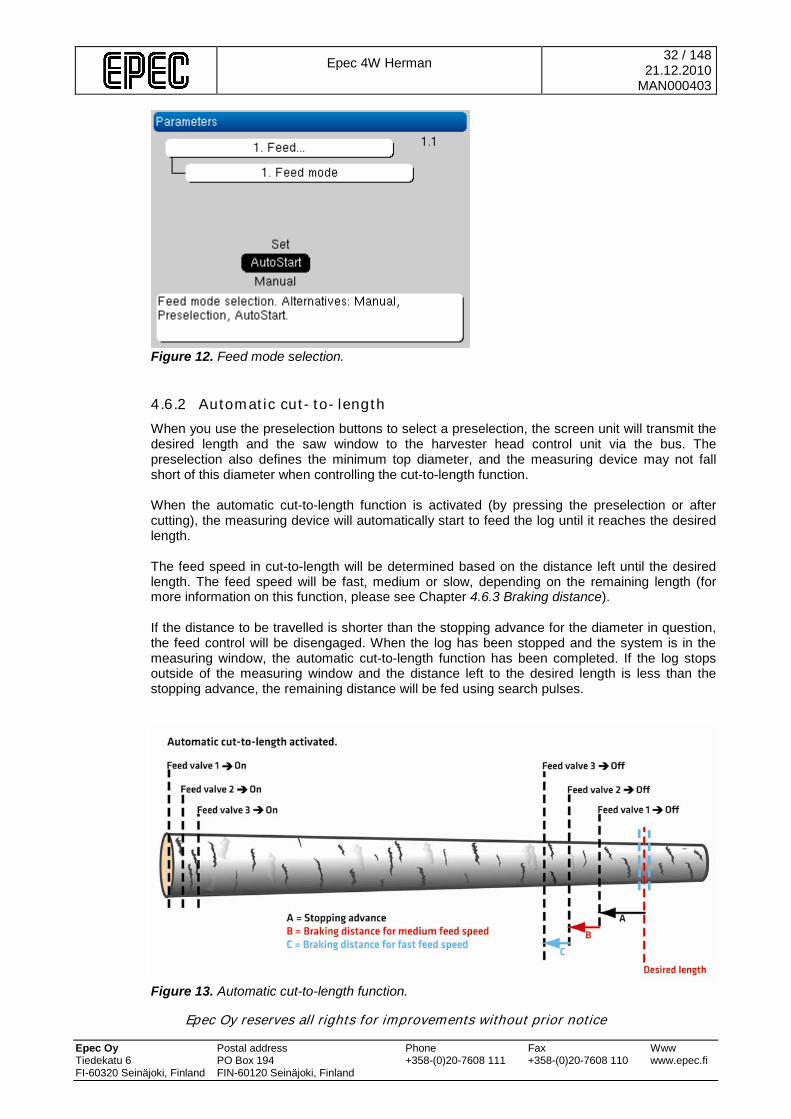
4.6.2 Automatic cut-to-length When you use the preselection buttons to select a preselection, the screen unit will transmit the desired length and the saw window to the harvester head control unit via the bus. The preselection also defines the minimum top diameter, and the measuring device may not fall short of this diameter when controlling the cut-to-length function.
When the automatic cut-to-length function is activated (by pressing the preselection or after cutting), the measuring device will automatically start to feed the log until it reaches the desired length. The feed speed in cut-to-length will be determined based on the distance left until the desired length. The feed speed will be fast, medium or slow, depending on the remaining length (for more information on this function, please see Chapter 4.6.3 Braking distance). If the distance to be travelled is shorter than the stopping advance for the diameter in question, the feed control will be disengaged. When the log has been stopped and the system is in the measuring window, the automatic cut-to-length function has been completed. If the log stops outside of the measuring window and the distance left to the desired length is less than the stopping advance, the remaining distance will be fed using search pulses.
Figure 13. Automatic cut-to-length function.

Epec 4W Herman
33 / 148 21.12.2010
MAN000403
Epec Oy reserves all rights for improvements without prior notice Epec Oy Postal address Phone Fax Www Tiedekatu 6 PO Box 194 +358-(0)20-7608 111 +358-(0)20-7608 110 www.epec.fi FI-60320 Seinäjoki, Finland FIN-60120 Seinäjoki, Finland
When the automatic cut-to-length starts, the feed valves will be engaged in stages as follows: valve 1 delay valve 2 delay valve 3 The delay between valve controls can be adjusted using a parameter.
4.6.3 Braking distance The braking distance is defined based on the tree thickness so that the minimum and maximum braking distance will be defined using parameters for the harvester head's maximum opening and zero opening (diameter zero), and the braking distance between the maximum and minimum distance will be linearly adjusted based on the log diameter. The thicker the log, the longer the braking distance. There are separate minimum and maximum braking distance parameters for fast and medium speed braking distances. Both braking distances depend on the tree thickness in the same manner. Distance remaining to desired length Feed speed When the distance remaining before the desired length is less than the fast speed braking distance plus the medium feed braking distance plus the stopping advance,
Feed speed will be calculated for medium speed.
When the distance remaining before the desired length is less than the medium speed braking distance plus the stopping advance,
Feed speed will be calculated for slow speed.
When the distance remaining before the desired length is less than the medium speed braking distance plus the stopping advance when feed starts,
Feed will be started using the slow speed.
When the distance remaining before the desired length is less than the fast speed braking distance plus the medium speed braking distance plus the stopping advance when feed starts,
Feed will be started using the medium speed.

Epec 4W Herman
34 / 148 21.12.2010
MAN000403
Epec Oy reserves all rights for improvements without prior notice Epec Oy Postal address Phone Fax Www Tiedekatu 6 PO Box 194 +358-(0)20-7608 111 +358-(0)20-7608 110 www.epec.fi FI-60320 Seinäjoki, Finland FIN-60120 Seinäjoki, Finland
Figure 14. Braking distance.
4.6.4 Stopping advance When the distance remaining before the desired length is less than the stopping advance for the diameter in question, the feed control will be disengaged and the system will wait until the log stops.
When the distance remaining before the desired length is less than the stopping advance for the diameter in question, the log will be controlled to the predefined length using search pulses if the log is not in the saw window. There are eight diameter categories which are automatically defined based on the maximum harvester head movement zone by dividing the movement zone into eight sections.
The stopping advance will be automatically adjusted based on the actual stopping distance and the diameter category.
4.6.5 Search pulses When the distance remaining to the desired length is less than the stopping advance for the diameter in question, the log will be controlled to the desired length using search pulses (if not in the sawing window). Search pulses control the feed valve until the pulse length defined by the parameter is reached or until the log reaches the saw window. If the pulse length is reached before the log reaches the measuring window, the feed control will be disengaged and a new pulse will be started when the log has stopped. This will be continued until the log stops inside the measuring window.
Epec 4W Herman
35 / 148 21.12.2010
MAN000403
Epec Oy reserves all rights for improvements without prior notice Epec Oy Postal address Phone Fax Www Tiedekatu 6 PO Box 194 +358-(0)20-7608 111 +358-(0)20-7608 110 www.epec.fi FI-60320 Seinäjoki, Finland FIN-60120 Seinäjoki, Finland
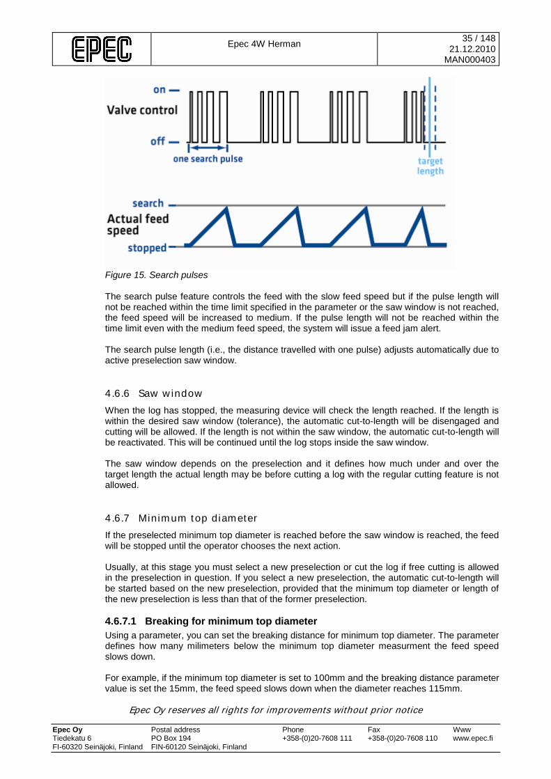
Figure 15. Search pulses The search pulse feature controls the feed with the slow feed speed but if the pulse length will not be reached within the time limit specified in the parameter or the saw window is not reached, the feed speed will be increased to medium. If the pulse length will not be reached within the time limit even with the medium feed speed, the system will issue a feed jam alert. The search pulse length (i.e., the distance travelled with one pulse) adjusts automatically due to active preselection saw window.
4.6.6 Saw window When the log has stopped, the measuring device will check the length reached. If the length is within the desired saw window (tolerance), the automatic cut-to-length will be disengaged and cutting will be allowed. If the length is not within the saw window, the automatic cut-to-length will be reactivated. This will be continued until the log stops inside the saw window. The saw window depends on the preselection and it defines how much under and over the target length the actual length may be before cutting a log with the regular cutting feature is not allowed.
4.6.7 Minimum top diameter If the preselected minimum top diameter is reached before the saw window is reached, the feed will be stopped until the operator chooses the next action. Usually, at this stage you must select a new preselection or cut the log if free cutting is allowed in the preselection in question. If you select a new preselection, the automatic cut-to-length will be started based on the new preselection, provided that the minimum top diameter or length of the new preselection is less than that of the former preselection.
4.6.7.1 Breaking for minimum top diameter Using a parameter, you can set the breaking distance for minimum top diameter. The parameter defines how many milimeters below the minimum top diameter measurment the feed speed slows down. For example, if the minimum top diameter is set to 100mm and the breaking distance parameter value is set the 15mm, the feed speed slows down when the diameter reaches 115mm.

Epec 4W Herman
36 / 148 21.12.2010
MAN000403
Epec Oy reserves all rights for improvements without prior notice Epec Oy Postal address Phone Fax Www Tiedekatu 6 PO Box 194 +358-(0)20-7608 111 +358-(0)20-7608 110 www.epec.fi FI-60320 Seinäjoki, Finland FIN-60120 Seinäjoki, Finland
4.6.8 Automatic pre-delimbing The pre-delimbing feature defines how much of the log will be fed over the desired length defined in the preselection before the log is controlled to the actual desired length. You can define pre-delimbing length using a parameter and it is the same in all preselections. You can engage or disengage the pre-delimbing feature of each preselection. The purpose with pre-delimbing is delimbing the log over the desired cutting length so that movements after cutting would be easier. When pre-delimbing has been activated, the log will be fed over the predefined length by the distance defined in the preselection. When the pre-delimbing is finished and the log has stopped in the measuring window, the automatic cut-to-length function will automatically start.
Figure 16. Pre-delimbing parameter. Pre-delimbing can also be activated manually by pressing the pre-selection buttons Shift2+Front knives open while in the processing state. When a pre-selection button activates feeding, pre-delimbing must be done regardless of if pre-delimbing is automatically specified for that pre-selection.
4.6.9 Slipping identification and branch chipper Slipping identification is always engaged (allowed by parameter) when logs are automatically fed. Slipping identification feature: • If the length sensor does not offer sufficiently many pulses during the slipping identification
time when the log is being automatically fed, the system will assume that the feed/log is stuck.
• When the slipping identification is activated during forwards feed, the branch chipper will be activated – if the branch chipper is available (parameter).
• In other cases, the automatic feed will be stopped and you will be notified of a jam/slipping alert.
• You can continue the automatic cut-to-length by pressing the preselection button again. The branch chipper: • When the slipping identification feature notes that the automatic forward feed is stuck, the
log will be fed backwards for the set distance at medium speed, after which the knives' pressure will be decreased and the tracks' pressure increased (parameter).

Epec 4W Herman
37 / 148 21.12.2010
MAN000403
Epec Oy reserves all rights for improvements without prior notice Epec Oy Postal address Phone Fax Www Tiedekatu 6 PO Box 194 +358-(0)20-7608 111 +358-(0)20-7608 110 www.epec.fi FI-60320 Seinäjoki, Finland FIN-60120 Seinäjoki, Finland
• Then, the log will be fed forwards at fast speed until the point where the log first got stuck has been exceeded by the distance set in the parameter. This function will be repeated a maximum of three times (parameter).
• If the point where the log got stuck has not been passed after three attempts, the automatic cut-to-length function will be stopped and the measuring device will issue a 'log stuck' alert.
• If the point where the log got stuck has been passed, the attempts will be reset and the automatic cut-to-length will be normally continued, i.e. the feeding speed will be adjusted as necessary and the pressures will be adjusted based on the log diameter.
This parameter can be used to define a delay from the beginning of feeding, after which the slipping control and identification will be taken into use.
Figure 17. Branch chipper.
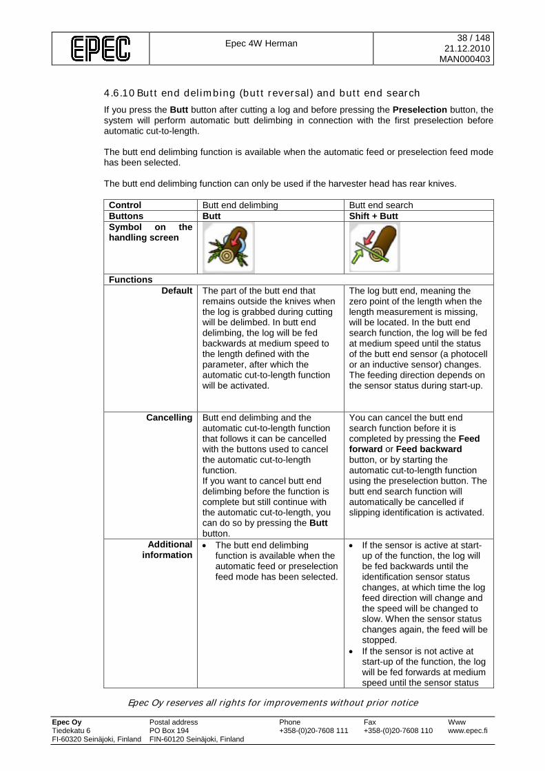
Epec 4W Herman
38 / 148 21.12.2010
MAN000403
Epec Oy reserves all rights for improvements without prior notice Epec Oy Postal address Phone Fax Www Tiedekatu 6 PO Box 194 +358-(0)20-7608 111 +358-(0)20-7608 110 www.epec.fi FI-60320 Seinäjoki, Finland FIN-60120 Seinäjoki, Finland
4.6.10 Butt end delimbing (butt reversal) and butt end search If you press the Butt button after cutting a log and before pressing the Preselection button, the system will perform automatic butt delimbing in connection with the first preselection before automatic cut-to-length.
The butt end delimbing function is available when the automatic feed or preselection feed mode has been selected. The butt end delimbing function can only be used if the harvester head has rear knives. Control Butt end delimbing Butt end search Buttons Butt Shift + Butt Symbol on the handling screen
Functions
Default The part of the butt end that remains outside the knives when the log is grabbed during cutting will be delimbed. In butt end delimbing, the log will be fed backwards at medium speed to the length defined with the parameter, after which the automatic cut-to-length function will be activated.
The log butt end, meaning the zero point of the length when the length measurement is missing, will be located. In the butt end search function, the log will be fed at medium speed until the status of the butt end sensor (a photocell or an inductive sensor) changes. The feeding direction depends on the sensor status during start-up.
Cancelling Butt end delimbing and the automatic cut-to-length function that follows it can be cancelled with the buttons used to cancel the automatic cut-to-length function. If you want to cancel butt end delimbing before the function is complete but still continue with the automatic cut-to-length, you can do so by pressing the Butt button.
You can cancel the butt end search function before it is completed by pressing the Feed forward or Feed backward button, or by starting the automatic cut-to-length function using the preselection button. The butt end search function will automatically be cancelled if slipping identification is activated.
Additional information
• The butt end delimbing function is available when the automatic feed or preselection feed mode has been selected.
• If the sensor is active at start-up of the function, the log will be fed backwards until the identification sensor status changes, at which time the log feed direction will change and the speed will be changed to slow. When the sensor status changes again, the feed will be stopped.
• If the sensor is not active at start-up of the function, the log will be fed forwards at medium speed until the sensor status

Epec 4W Herman
39 / 148 21.12.2010
MAN000403
Epec Oy reserves all rights for improvements without prior notice Epec Oy Postal address Phone Fax Www Tiedekatu 6 PO Box 194 +358-(0)20-7608 111 +358-(0)20-7608 110 www.epec.fi FI-60320 Seinäjoki, Finland FIN-60120 Seinäjoki, Finland
changes, at which time the log feed will be stopped.
• Every time the sensor status changes, the length display will show the distance from the sensor to the saw (parameter).
4.7 Cutting control • Always activate the saw by pressing the Saw button. • The only function allowed when one of the saws is outside of its housing is slow feed
backwards. • Cutting cannot be performed when the log is moving or when the feed mode is active. • The saw bar will automatically retract into its housing when it is not currently in use. • When you press the Saw button, the chain rotator motor will start first and the bar will come
out of the housing after a predefined delay.
4.7.1 Saw function modes in cutting You can select the saw function mode, manual or automatic, using a parameter. When you have selected the automatic cutting mode, you can use preliminary cutting with the automatic cut-to-length function. Manual cutting Automatic cutting • The cutting will start when you press the
Saw button and will remain active until you release the button or until the saw control* is reached. When you release the button, the saw will return back to its housing.
• If you press the Saw button a second time before the saw blade has returned to its housing, the system will continue cutting until you release the button.
• The cutting will start when you press the Saw button and will remain active until the saw control* is reached.
• If you press the Saw button a second time before the saw blade has returned to its housing, the system will continue cutting until you release the button.
• If you press the Saw button when the automatic cut-to-length is active, the automatic cut-to-length will be cancelled.
• If you briefly press the Saw button when the automatic cut-to-length is active, the preliminary cutting function will be activated.
Preliminary cutting • You can activate preliminary cutting by briefly
pressing the Saw button when the automatic cut-to-length function is active; this will cause cutting to automatically start when the log has stopped in the desired length saw window.
• In preliminary cutting, the log will be cut until the saw control limit is reached.
• Preliminary cutting will remain valid for one cutting at a time only, and thus you must activate it by pressing the button each time you are cutting a log.
• You can cancel the preliminary cutting before
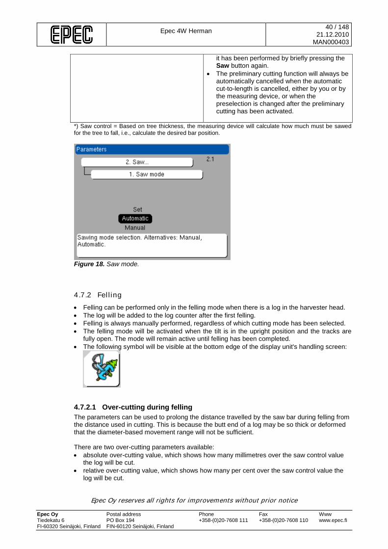
Epec 4W Herman
40 / 148 21.12.2010
MAN000403
Epec Oy reserves all rights for improvements without prior notice Epec Oy Postal address Phone Fax Www Tiedekatu 6 PO Box 194 +358-(0)20-7608 111 +358-(0)20-7608 110 www.epec.fi FI-60320 Seinäjoki, Finland FIN-60120 Seinäjoki, Finland
it has been performed by briefly pressing the Saw button again.
• The preliminary cutting function will always be automatically cancelled when the automatic cut-to-length is cancelled, either by you or by the measuring device, or when the preselection is changed after the preliminary cutting has been activated.
*) Saw control = Based on tree thickness, the measuring device will calculate how much must be sawed for the tree to fall, i.e., calculate the desired bar position.
Figure 18. Saw mode.
4.7.2 Felling • Felling can be performed only in the felling mode when there is a log in the harvester head. • The log will be added to the log counter after the first felling. • Felling is always manually performed, regardless of which cutting mode has been selected. • The felling mode will be activated when the tilt is in the upright position and the tracks are
fully open. The mode will remain active until felling has been completed. • The following symbol will be visible at the bottom edge of the display unit's handling screen:
4.7.2.1 Over-cutting during felling The parameters can be used to prolong the distance travelled by the saw bar during felling from the distance used in cutting. This is because the butt end of a log may be so thick or deformed that the diameter-based movement range will not be sufficient. There are two over-cutting parameters available: • absolute over-cutting value, which shows how many millimetres over the saw control value
the log will be cut. • relative over-cutting value, which shows how many per cent over the saw control value the
log will be cut.
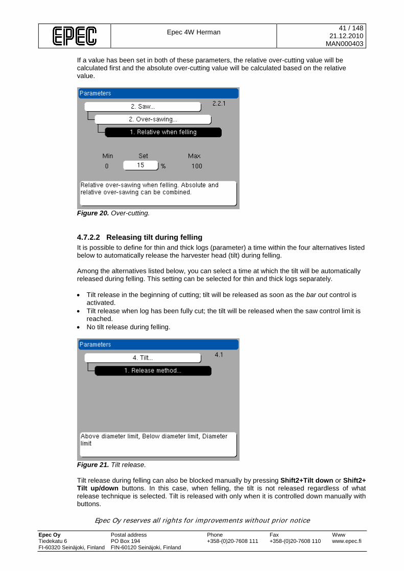
Epec 4W Herman
41 / 148 21.12.2010
MAN000403
Epec Oy reserves all rights for improvements without prior notice Epec Oy Postal address Phone Fax Www Tiedekatu 6 PO Box 194 +358-(0)20-7608 111 +358-(0)20-7608 110 www.epec.fi FI-60320 Seinäjoki, Finland FIN-60120 Seinäjoki, Finland
If a value has been set in both of these parameters, the relative over-cutting value will be calculated first and the absolute over-cutting value will be calculated based on the relative value.
Figure 20. Over-cutting.
4.7.2.2 Releasing tilt during felling It is possible to define for thin and thick logs (parameter) a time within the four alternatives listed below to automatically release the harvester head (tilt) during felling. Among the alternatives listed below, you can select a time at which the tilt will be automatically released during felling. This setting can be selected for thin and thick logs separately.
• Tilt release in the beginning of cutting; tilt will be released as soon as the bar out control is
activated. • Tilt release when log has been fully cut; the tilt will be released when the saw control limit is
reached. • No tilt release during felling.
Figure 21. Tilt release. Tilt release during felling can also be blocked manually by pressing Shift2+Tilt down or Shift2+ Tilt up/down buttons. In this case, when felling, the tilt is not released regardless of what release technique is selected. Tilt is released with only when it is controlled down manually with buttons.

Epec 4W Herman
42 / 148 21.12.2010
MAN000403
Epec Oy reserves all rights for improvements without prior notice Epec Oy Postal address Phone Fax Www Tiedekatu 6 PO Box 194 +358-(0)20-7608 111 +358-(0)20-7608 110 www.epec.fi FI-60320 Seinäjoki, Finland FIN-60120 Seinäjoki, Finland
4.7.2.3 Stem counter
The stem counter will only work when the tracks are fully closed.
After felling and the first cutting, each stem will be added under the preselection that was selected when the stem feeding started. A minimum of 800 mm of the stem must be fed (the default value that can be changed in the maintenance mode) before it will be added to the felled stems after cutting.
4.7.3 Forced cutting Forced cutting is to be used when, for example, the saw bar is stuck behind a log when returning back to the housing. You can activate forced cutting under any circumstances when the log is not moving by simultaneously pressing the Harvester head closed and Saw buttons. Control Forced cutting Buttons Harvester head closed + Saw
Functions Basic function Forced cutting is to be used when, for example, the saw bar got
stuck behind a log when returning back to the housing. You can activate forced cutting at any time as long as the log is not moving.
Additional information
You can simultaneously press the Harvester head closed and Saw buttons, or you can first press the Harvester head button and then the Saw button. If you press the Saw button before pressing the Harvester head button, you must release the Saw button before you can activate forced cutting. Forced cutting will remain active until you release both or one of the above-mentioned buttons.
4.7.4 Clearing function
You can activate the clearing function only when the tilt is in the upright position.
To activate the clearing function, press the Harvester head open + Saw buttons, either simultaneously or first the Harvester head open button and then the Saw button. Control Clearing function Buttons Harvester head open + Saw
Symbol on the handling screen
Functions
Basic function The clearing function locks the tilt into the vertical position and the saw out of its housing. The saw will be kept out of the housing until you release the saw button.
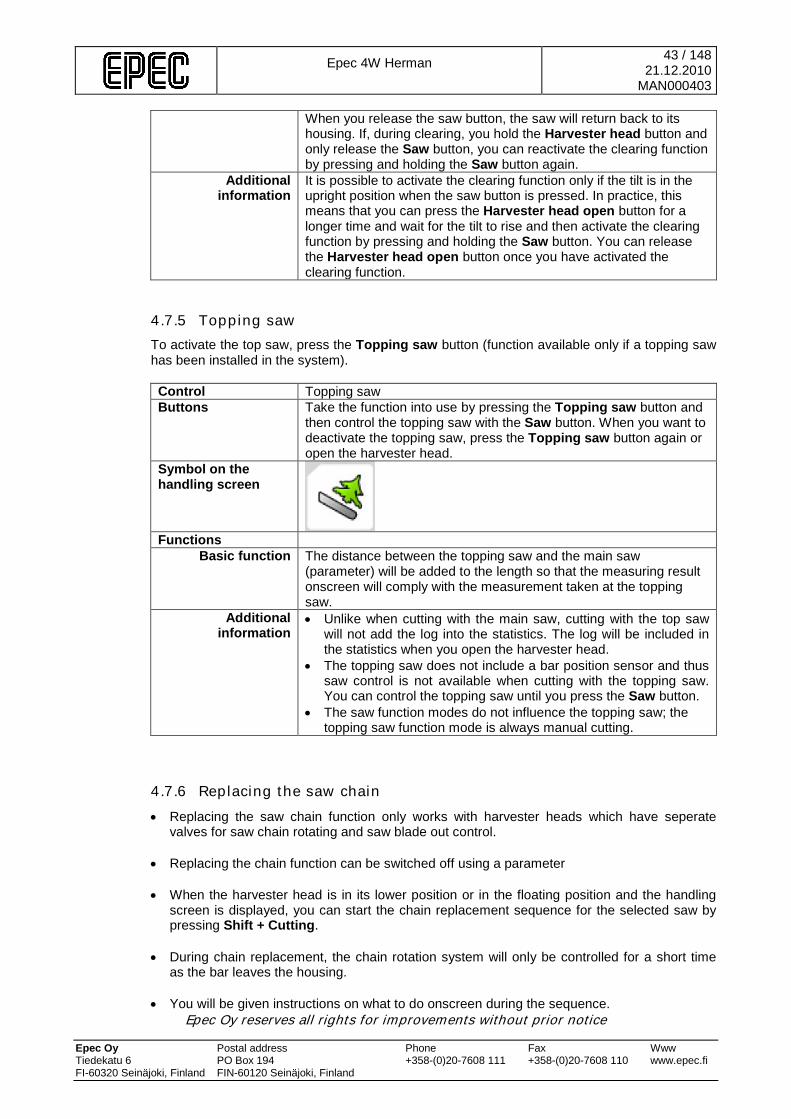
Epec 4W Herman
43 / 148 21.12.2010
MAN000403
Epec Oy reserves all rights for improvements without prior notice Epec Oy Postal address Phone Fax Www Tiedekatu 6 PO Box 194 +358-(0)20-7608 111 +358-(0)20-7608 110 www.epec.fi FI-60320 Seinäjoki, Finland FIN-60120 Seinäjoki, Finland
When you release the saw button, the saw will return back to its housing. If, during clearing, you hold the Harvester head button and only release the Saw button, you can reactivate the clearing function by pressing and holding the Saw button again.
Additional information
It is possible to activate the clearing function only if the tilt is in the upright position when the saw button is pressed. In practice, this means that you can press the Harvester head open button for a longer time and wait for the tilt to rise and then activate the clearing function by pressing and holding the Saw button. You can release the Harvester head open button once you have activated the clearing function.
4.7.5 Topping saw To activate the top saw, press the Topping saw button (function available only if a topping saw has been installed in the system). Control Topping saw Buttons Take the function into use by pressing the Topping saw button and
then control the topping saw with the Saw button. When you want to deactivate the topping saw, press the Topping saw button again or open the harvester head.
Symbol on the handling screen
Functions
Basic function The distance between the topping saw and the main saw (parameter) will be added to the length so that the measuring result onscreen will comply with the measurement taken at the topping saw.
Additional information
• Unlike when cutting with the main saw, cutting with the top saw will not add the log into the statistics. The log will be included in the statistics when you open the harvester head.
• The topping saw does not include a bar position sensor and thus saw control is not available when cutting with the topping saw. You can control the topping saw until you press the Saw button.
• The saw function modes do not influence the topping saw; the topping saw function mode is always manual cutting.
4.7.6 Replacing the saw chain • Replacing the saw chain function only works with harvester heads which have seperate
valves for saw chain rotating and saw blade out control. • Replacing the chain function can be switched off using a parameter • When the harvester head is in its lower position or in the floating position and the handling
screen is displayed, you can start the chain replacement sequence for the selected saw by pressing Shift + Cutting.
• During chain replacement, the chain rotation system will only be controlled for a short time
as the bar leaves the housing. • You will be given instructions on what to do onscreen during the sequence.
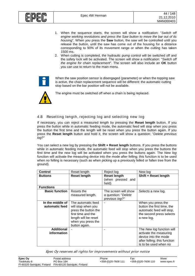
Epec 4W Herman
44 / 148 21.12.2010
MAN000403
Epec Oy reserves all rights for improvements without prior notice Epec Oy Postal address Phone Fax Www Tiedekatu 6 PO Box 194 +358-(0)20-7608 111 +358-(0)20-7608 110 www.epec.fi FI-60320 Seinäjoki, Finland FIN-60120 Seinäjoki, Finland
1. When the sequence starts, the screen will show a notification: ”Switch off
engine working revolutions and press the Saw button to move the bar out of its housing”. When you press the Saw button, the saw will be controlled until you release the button, until the saw has come out of the housing for a distance corresponding to 90% of its movement range or when the cutting has taken 1500 ms.
2. When cutting is completed, the hydraulic pump control will be switched off and the safety lock will be activated. The screen will show a notification: ”Switch off the engine for chain replacement”. The screen will also include an OK button you can use to return to the main menu.
When the saw position sensor is disengaged (parameter) or when the topping saw is active, the chain replacement sequence will be different: the automatic cutting stop based on the bar position will not be available.
The engine must be switched off when a chain is being replaced.
4.8 Resetting length, rejecting log and selecting new log If necessary, you can reject a measured length by pressing the Reset length button. If you press the button while in automatic feeding mode, the automatic feed will stop when you press the button the first time and the length will be reset when you press the button again. If you press the Reset length button and hold it, the screen will show a question: ”Delete previous log?” You can select a new log by pressing the Shift + Reset length buttons. If you press the buttons while in automatic feeding mode, the automatic feed will stop when you press the buttons the first time and the new log will be activated when you press the buttons again. The New log function will activate the measuring device into the mode after felling; this function is to be used when no felling is necessary (such as when picking up a previously felled or fallen tree from the ground). Control Reset length Reject log New log Buttons Reset length Reset length
(when pressed and held)
Shift + Reset length
Functions Basic function Resets the
measured length. The screen will show a question: ”Delete previous log?”
Selects a new log.
In the middle of automatic feed
The automatic feed will stop when you press the button the first time and the length will be reset when you press the button again.
- When you press the button the first time, the automatic feed will stop, the second press selects a new log.
Additional information
- - The New log function will activate the measuring device into the mode after felling; this function is to be used when no

Epec 4W Herman
45 / 148 21.12.2010
MAN000403
Epec Oy reserves all rights for improvements without prior notice Epec Oy Postal address Phone Fax Www Tiedekatu 6 PO Box 194 +358-(0)20-7608 111 +358-(0)20-7608 110 www.epec.fi FI-60320 Seinäjoki, Finland FIN-60120 Seinäjoki, Finland
felling is necessary (such as when picking up a previously felled or fallen tree from the ground).
4.9 Colour marking The colour marking selections are preselection-specific. There are two colours available, and these colours can be used together or separately. The colour markings are made on a log that drops from the harvester head during cutting. The colour marking valves are controlled in relation to the saw position. The parameters are used to set the starting point of the colour marking in relation to saw control (cutting of the log). If the value is negative, the colour marking control will start before the bar reaches the saw control point. If the value is positive, the colour marking will start after the saw control point has been reached. The parameter is also used to set the colour marking valve control time in milliseconds. The display unit's Harvester head control screen enables manual control of the colour marking valves when they are tested. You can manually control the colour marking valve 1 by pressing Shift2 + Head open, and the colour marking valve 2 by pressing Shift2 + Head close.
4.10 Stump treatment You can disable the stump treatment function by using a parameter.
Figure 22. Stump treatment parameters.
4.10.1 Stump treatment in connection with felling If the automatic stump treatment function is active (parameter), the stump treatment will automatically take place during each felling. You can disable the stump treatment function for one felling by pressing the Shift 2 + Butt buttons before felling. If the automatic stump treatment function is disabled (parameter), you can perform stump treatment for one felling by pressing the Shift 2 + Butt buttons before felling. During felling, the stump treatment pump will be controlled as long as the bar is being extracted.

Epec 4W Herman
46 / 148 21.12.2010
MAN000403
Epec Oy reserves all rights for improvements without prior notice Epec Oy Postal address Phone Fax Www Tiedekatu 6 PO Box 194 +358-(0)20-7608 111 +358-(0)20-7608 110 www.epec.fi FI-60320 Seinäjoki, Finland FIN-60120 Seinäjoki, Finland
When stump treatment is active, the following image is shown at the bottom edge of the handling screen:
4.10.2 Stump treatment for the stump of a previously felled tree This function only works with harvester heads which have seperate valves for saw chain rotating and saw blade out control. When the tilt is in the upright position, you can perform stump treatment for the stump of a previously felled tree by pressing and holding the Shift2 + Butt buttons. The stump treatment pump and bar will be controlled as long as you release the Butt button (you can release the Shift2 button when you have pressed the Butt button).
4.11 Track pressure measuring The track pressure sensor type (current or voltage message) can be selected by a parameter. Using a parameter, you can also select that there is no sensor installed. There is a pressure sensor in the harvester head which continuously measures the track pressure. The track pressure is shown on the handling screen.
4.12 Hydraulic pumps The measuring device can support the simultaneous control of a maximum of three hydraulic pumps. • When the measuring device is installed, the pumps are configured as proportional pumps or
ON/OFF-type pumps and the pumps to be used are selected. Furthermore, the pumps to activate each movement and the capacity level have been configured.
•
Figure 23. Pump window 1 • The possible movements are:
o Rotator o Tilt
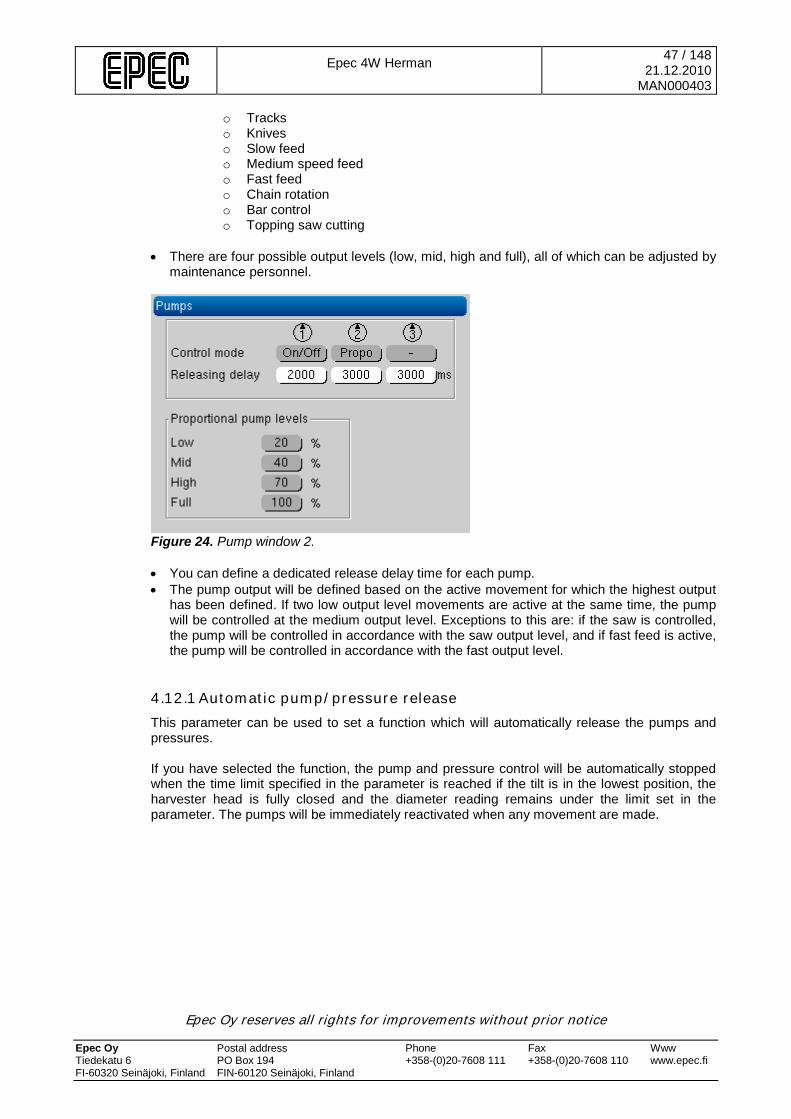
Epec 4W Herman
47 / 148 21.12.2010
MAN000403
Epec Oy reserves all rights for improvements without prior notice Epec Oy Postal address Phone Fax Www Tiedekatu 6 PO Box 194 +358-(0)20-7608 111 +358-(0)20-7608 110 www.epec.fi FI-60320 Seinäjoki, Finland FIN-60120 Seinäjoki, Finland
o Tracks o Knives o Slow feed o Medium speed feed o Fast feed o Chain rotation o Bar control o Topping saw cutting
• There are four possible output levels (low, mid, high and full), all of which can be adjusted by
maintenance personnel.
Figure 24. Pump window 2. • You can define a dedicated release delay time for each pump. • The pump output will be defined based on the active movement for which the highest output
has been defined. If two low output level movements are active at the same time, the pump will be controlled at the medium output level. Exceptions to this are: if the saw is controlled, the pump will be controlled in accordance with the saw output level, and if fast feed is active, the pump will be controlled in accordance with the fast output level.
4.12.1 Automatic pump/pressure release This parameter can be used to set a function which will automatically release the pumps and pressures. If you have selected the function, the pump and pressure control will be automatically stopped when the time limit specified in the parameter is reached if the tilt is in the lowest position, the harvester head is fully closed and the diameter reading remains under the limit set in the parameter. The pumps will be immediately reactivated when any movement are made.

Epec 4W Herman
48 / 148 21.12.2010
MAN000403
Epec Oy reserves all rights for improvements without prior notice Epec Oy Postal address Phone Fax Www Tiedekatu 6 PO Box 194 +358-(0)20-7608 111 +358-(0)20-7608 110 www.epec.fi FI-60320 Seinäjoki, Finland FIN-60120 Seinäjoki, Finland
5 GRAPHICAL USER INTERFACE
5.1 Display buttons and programming wheel The programming wheel is mainly used to move within screens and from one screen to another. There are also five buttons at the bottom edge of the display unit. These five buttons perform the same functions on all screens (unless there are separately specified buttons on the screens themselves).
Figure 25. The display unit buttons.
Figure 26. The programming wheel. The button functions on most of the screens are: 1. Back
• Return to the previous screen. • The red Cancel button on the programming wheel will perform the same function.
2. Previous • Reducing a numerical value when adjusting a value. • Browsing backwards to previous screen components. • The same functions will be performed when you rotate the programming wheel counter-
clockwise. 3. OK
• When adjusting a value, approving and saving a new value. • Transferring to the editing mode. • Under normal circumstances, this button can be used to approve a selection (i.e.,
perform a function or open a screen).
Back Previous OK Next Info
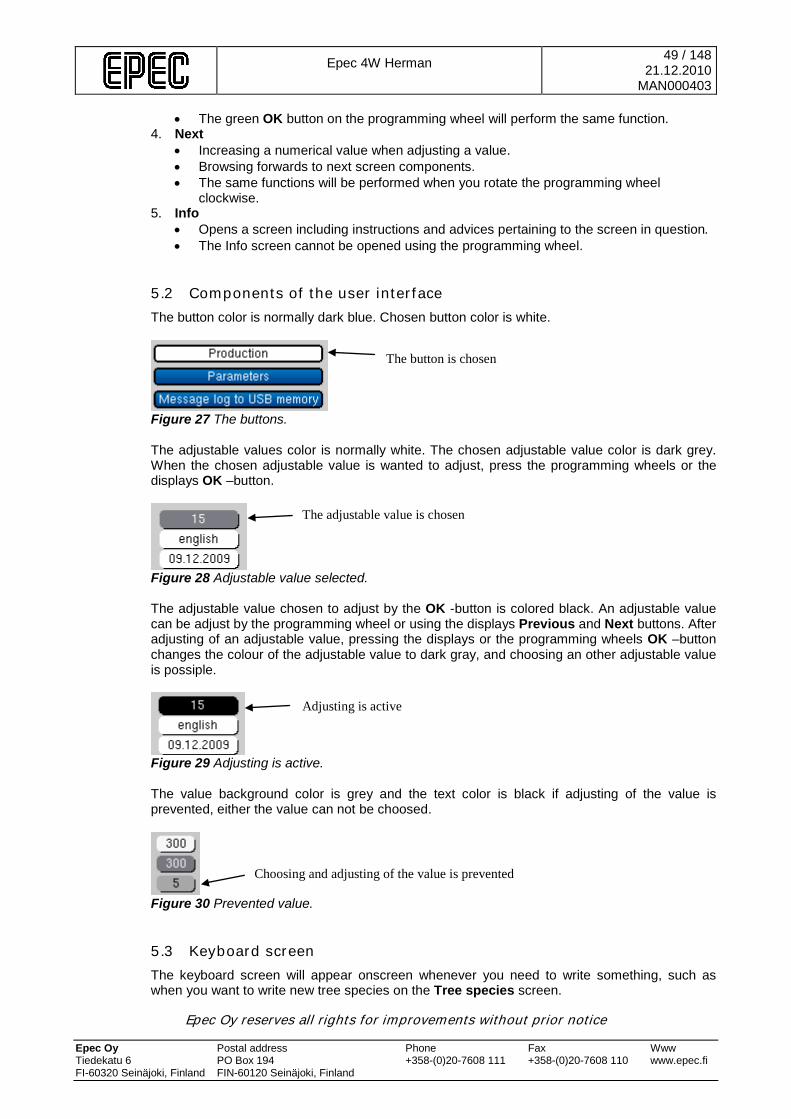
Epec 4W Herman
49 / 148 21.12.2010
MAN000403
Epec Oy reserves all rights for improvements without prior notice Epec Oy Postal address Phone Fax Www Tiedekatu 6 PO Box 194 +358-(0)20-7608 111 +358-(0)20-7608 110 www.epec.fi FI-60320 Seinäjoki, Finland FIN-60120 Seinäjoki, Finland
• The green OK button on the programming wheel will perform the same function. 4. Next
• Increasing a numerical value when adjusting a value. • Browsing forwards to next screen components. • The same functions will be performed when you rotate the programming wheel
clockwise. 5. Info
• Opens a screen including instructions and advices pertaining to the screen in question. • The Info screen cannot be opened using the programming wheel.
5.2 Components of the user interface The button color is normally dark blue. Chosen button color is white.
Figure 27 The buttons. The adjustable values color is normally white. The chosen adjustable value color is dark grey. When the chosen adjustable value is wanted to adjust, press the programming wheels or the displays OK –button.
Figure 28 Adjustable value selected. The adjustable value chosen to adjust by the OK -button is colored black. An adjustable value can be adjust by the programming wheel or using the displays Previous and Next buttons. After adjusting of an adjustable value, pressing the displays or the programming wheels OK –button changes the colour of the adjustable value to dark gray, and choosing an other adjustable value is possiple.
Figure 29 Adjusting is active. The value background color is grey and the text color is black if adjusting of the value is prevented, either the value can not be choosed.
Figure 30 Prevented value.
5.3 Keyboard screen The keyboard screen will appear onscreen whenever you need to write something, such as when you want to write new tree species on the Tree species screen.
The button is chosen
The adjustable value is chosen
Adjusting is active
Choosing and adjusting of the value is prevented
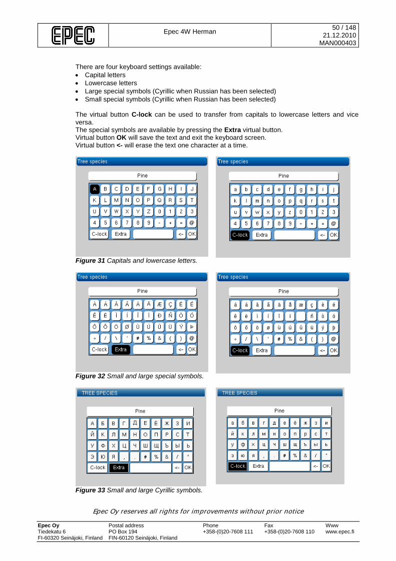
Epec 4W Herman
50 / 148 21.12.2010
MAN000403
Epec Oy reserves all rights for improvements without prior notice Epec Oy Postal address Phone Fax Www Tiedekatu 6 PO Box 194 +358-(0)20-7608 111 +358-(0)20-7608 110 www.epec.fi FI-60320 Seinäjoki, Finland FIN-60120 Seinäjoki, Finland
There are four keyboard settings available: • Capital letters • Lowercase letters • Large special symbols (Cyrillic when Russian has been selected) • Small special symbols (Cyrillic when Russian has been selected) The virtual button C-lock can be used to transfer from capitals to lowercase letters and vice versa. The special symbols are available by pressing the Extra virtual button. Virtual button OK will save the text and exit the keyboard screen. Virtual button <- will erase the text one character at a time.
Figure 31 Capitals and lowercase letters.
Figure 32 Small and large special symbols.
Figure 33 Small and large Cyrillic symbols.

Epec 4W Herman
51 / 148 21.12.2010
MAN000403
Epec Oy reserves all rights for improvements without prior notice Epec Oy Postal address Phone Fax Www Tiedekatu 6 PO Box 194 +358-(0)20-7608 111 +358-(0)20-7608 110 www.epec.fi FI-60320 Seinäjoki, Finland FIN-60120 Seinäjoki, Finland
5.4 Main menu and safety lock Normally, when you switch on the display unit, the main menu will appear. An exception to this is the first time you switch on the display unit. The top row of the main menu shows the name of the active work area. The bottom row shows an explanation of the active button.
Figure 34 The main menu. Safety lock When the system is turned on, the safety lock will be activated. When the safety lock is engaged, the handling screen cannot be opened. When the safety lock is engaged, a lock symbol can be seen on all screens in the top corner and the main menu handling screen icon will also include the lock symbol:
Figure 35 Safety lock engaged. To open the safety lock, activate the safety switch and then press Shift + Harvester head closed. The safety lock will be reengaged • when the system is booted • when the safety switch is triggered • in connection with certain functions (such as the chain replacement sequence) Submenus The main menu is divided into six submenus: Handling, Work area, Calibration, Diagnostics, Settings and Reporting. The table below includes a brief description of each submenu. Handling
Opens a screen that is used when the measuring device is normally used. Shows the measuring device's current selections, any alarms, counters and statistics. There is more information on these functions in Chapter 5.4.1 Handling
Active work area
An explanation of the active button
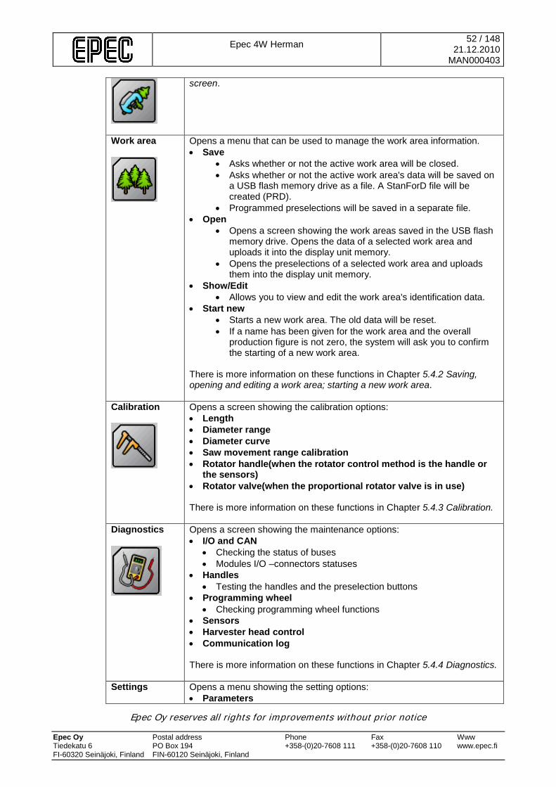
Epec 4W Herman
52 / 148 21.12.2010
MAN000403
Epec Oy reserves all rights for improvements without prior notice Epec Oy Postal address Phone Fax Www Tiedekatu 6 PO Box 194 +358-(0)20-7608 111 +358-(0)20-7608 110 www.epec.fi FI-60320 Seinäjoki, Finland FIN-60120 Seinäjoki, Finland
screen.
Work area
Opens a menu that can be used to manage the work area information. • Save
• Asks whether or not the active work area will be closed. • Asks whether or not the active work area's data will be saved on
a USB flash memory drive as a file. A StanForD file will be created (PRD).
• Programmed preselections will be saved in a separate file. • Open
• Opens a screen showing the work areas saved in the USB flash memory drive. Opens the data of a selected work area and uploads it into the display unit memory.
• Opens the preselections of a selected work area and uploads them into the display unit memory.
• Show/Edit • Allows you to view and edit the work area's identification data.
• Start new • Starts a new work area. The old data will be reset. • If a name has been given for the work area and the overall
production figure is not zero, the system will ask you to confirm the starting of a new work area.
There is more information on these functions in Chapter 5.4.2 Saving, opening and editing a work area; starting a new work area.
Calibration
Opens a screen showing the calibration options: • Length • Diameter range • Diameter curve • Saw movement range calibration • Rotator handle(when the rotator control method is the handle or
the sensors) • Rotator valve(when the proportional rotator valve is in use) There is more information on these functions in Chapter 5.4.3 Calibration.
Diagnostics
Opens a screen showing the maintenance options: • I/O and CAN
• Checking the status of buses • Modules I/O –connectors statuses
• Handles • Testing the handles and the preselection buttons
• Programming wheel • Checking programming wheel functions
• Sensors • Harvester head control • Communication log There is more information on these functions in Chapter 5.4.4 Diagnostics.
Settings
Opens a menu showing the setting options: • Parameters

Epec 4W Herman
53 / 148 21.12.2010
MAN000403
Epec Oy reserves all rights for improvements without prior notice Epec Oy Postal address Phone Fax Www Tiedekatu 6 PO Box 194 +358-(0)20-7608 111 +358-(0)20-7608 110 www.epec.fi FI-60320 Seinäjoki, Finland FIN-60120 Seinäjoki, Finland
• Squeeze pressure • Tilt pressure • Opening pulses • Knives vibration • Rotator • Pumps • Saw bar • Other parameters
• Only the parameters you as the operator can adjust will be shown and can be changed.
• Authorised service agents can browse and adjust all parameters.
• Preselections • Tree species names • Timber assortment names • Display settings • Default settings
• A new installation • Factory settings • Restoring the default settings
• Software • Options There is more information on these functions in Chapter 5.4.5 Settings.
Reporting
Opens a menu showing the reporting options: • Production
• To display • To printer • To file • Work area (PRD) to file
• Parameters • To printer • To file
• Piece printout • To printer, if it is connected to the system • To file, if printout to the printer does not work
• Calibration printout • To printer, if it is connected to the system • To file, if printout to the printer does not work
• Message log to USB memory • To file
There is more information on these functions in Chapter 5.4.6 Reporting.

Epec 4W Herman
54 / 148 21.12.2010
MAN000403
Epec Oy reserves all rights for improvements without prior notice Epec Oy Postal address Phone Fax Www Tiedekatu 6 PO Box 194 +358-(0)20-7608 111 +358-(0)20-7608 110 www.epec.fi FI-60320 Seinäjoki, Finland FIN-60120 Seinäjoki, Finland
5.4.1 Handling screen The handling screen is displayed when the measuring device is normally used. There are four functional parts on the screen:
Figure 36 The Handling screen. There is more information on the functional parts in the following chapters.
5.4.1.1 Section 1: Info bar and sound signal There is an info bar at the top of the screen. This bar includes alarms, other messages and the time. There are three types of messages: alarms, alerts and info. The symbol in front of the message shows which message type it is. If the message is an alarm, its background will flash red. level/group Alarm Alert Info shown as
Background flashes red
priority 1 2 3 sound signal
(500ms On, 500ms Off) repeated continuousely,
mute the sound by pressing the OK button
(200ms On, 50ms Off)
maximum 4 pulses if not muted by pressing the
OK button
(150ms On)
1 pulse
procedure Shown until the OK button is pressed or until a new alarm is activated.
Shown until the OK button is pressed or until a new alarm/alert is activated.
Shown until the OK button is pressed or until a new alarm/alert/info is activated. Stops automatically after 5 seconds.
In the info bar, the way the message is presented depends on it’s priority. Often, if more then one message is active at the same time, the message with the higher priority is shown. If there are many messages active at the same time with the same priority level, the last message is shown and the other active messages are in line by order. You can scroll through these messages by using the arrow button and by pressing the OK button.

Epec 4W Herman
55 / 148 21.12.2010
MAN000403
Epec Oy reserves all rights for improvements without prior notice Epec Oy Postal address Phone Fax Www Tiedekatu 6 PO Box 194 +358-(0)20-7608 111 +358-(0)20-7608 110 www.epec.fi FI-60320 Seinäjoki, Finland FIN-60120 Seinäjoki, Finland
If the info bar shows a message and there are other active messages with a lower priorty, the lower priorty messages are shown in the info bar for 3 seconds and then they move to the line (if OK button is not pressed). After this, the higher priority message is shown. Sound signals are assigned to all messages depending on their priority level. Sound signals accompany messages when they are activated the first time after the measuring device is booted, except for Info level messages, which are accompanied by the sound signal every time. Also, when you proceed to the sawing window and measurements are under the minimum top diameter, there is a sound signal. This sound signal can be controlled off seperately for alarms, alerts, info, proceeding to the sawing window and for minimum top diameter.
Figure 37 Sound signal when proceeding to the sawing window (50ms On, 30ms Off).
Figure 38 Sound signal when under the minimum top diameter (100ms On, 30ms Off).
5.4.1.2 Section 2: Length and diameter screen The middle part of the screen includes the length and diameter showing the log length and diameter information.
Length and diameter:
• The field on the left shows the log
length and the field on the right the diameter.
Diameter unknown:
• When the system is booted and it
enters the handling mode, you must open and close the harvester head a couple of times for the diameter to appear onscreen. If the diameter is unknown, the diameter field will include a flashing message "Open and close head".
• The diameter field background is grey when the diameter is unknown.
Length unknown:
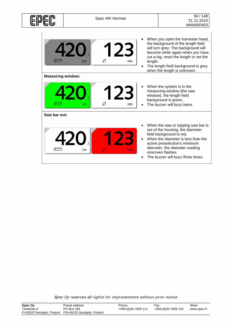
Epec 4W Herman
56 / 148 21.12.2010
MAN000403
Epec Oy reserves all rights for improvements without prior notice Epec Oy Postal address Phone Fax Www Tiedekatu 6 PO Box 194 +358-(0)20-7608 111 +358-(0)20-7608 110 www.epec.fi FI-60320 Seinäjoki, Finland FIN-60120 Seinäjoki, Finland
• When you open the harvester head,
the background of the length field will turn grey. The background will become white again when you have cut a log, reset the length or set the length.
• The length field background is grey when the length is unknown.
Measuring window:
• When the system is in the
measuring window (the saw window), the length field background is green.
• The buzzer will buzz twice.
Saw bar out:
• When the saw or topping saw bar is
out of the housing, the diameter field background is red.
• When the diameter is less than the active preselection's minimum diameter, the diameter reading onscreen flashes.
• The buzzer will buzz fhree times.

Epec 4W Herman
57 / 148 21.12.2010
MAN000403
Epec Oy reserves all rights for improvements without prior notice Epec Oy Postal address Phone Fax Www Tiedekatu 6 PO Box 194 +358-(0)20-7608 111 +358-(0)20-7608 110 www.epec.fi FI-60320 Seinäjoki, Finland FIN-60120 Seinäjoki, Finland
5.4.1.3 Section 3: Active preselection information The bottom part of the handling screen shows the active preselection's information, i.e., the settings that have been selected in the Settings submenu.
Figure 39 Active preselection information. Explanations of the additional preselection options:
1. Tree species 2. Desired length and tolerance 3. Tree assortment 4. Additional preselection options
o FC: Free cut o CM: Colour marking o DB: Debarking, if available
5. Minimum diameter 6. Tracks’s compression pressure 7. Total capacity of the logs registered to the pre-selection (cubic meters). 8. Total amount of running meters registerd to the pre-selection. 9. The quantity of logs registerd to the pre-selection. 10. Preselection number
If a preselection where the length is zero has been selected, the following announcement will be displayed:
Figure 40 Preselection not in use.
5.4.1.4 Section 4: Status information The bottom edge of the handling screen shows the system status as symbols.
Figure 41 An example of status information. There are seventeen status information symbols. There is an order of priority for the symbols: if two or more functions using the same symbol field are simultaneously active, the symbol with the highest priority will be displayed. The figure below shows the symbols in their order of priority (the highest priority at the top).
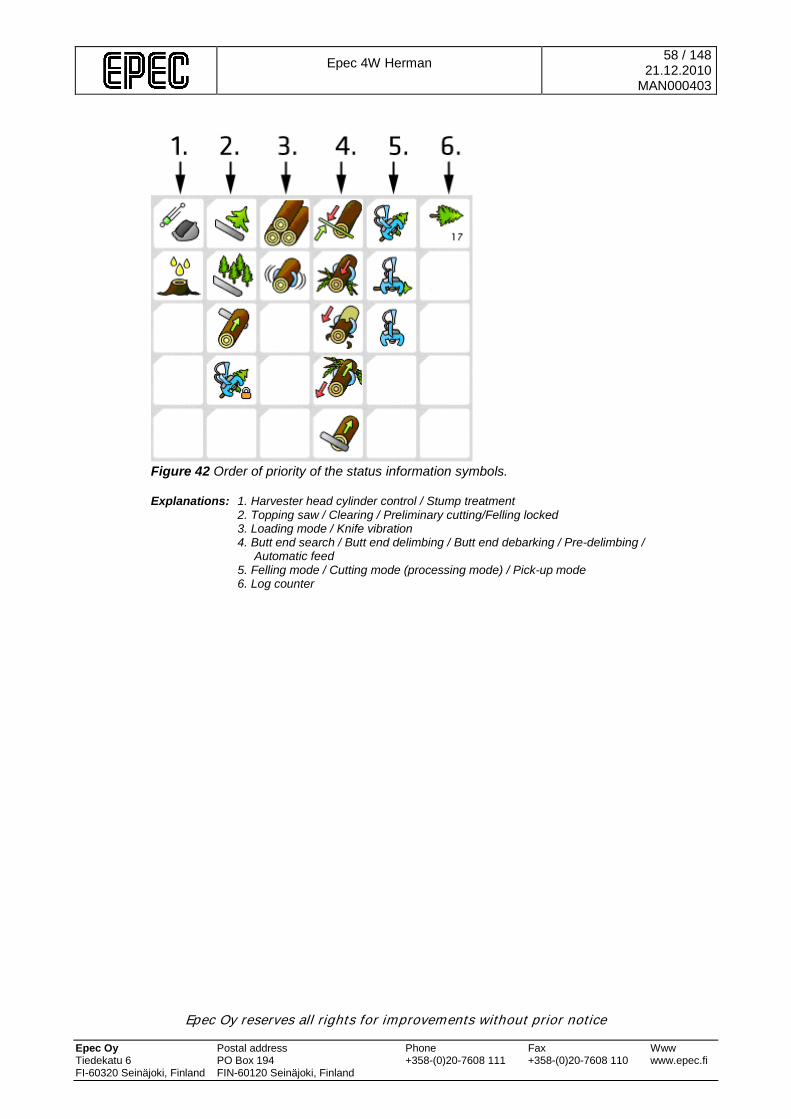
Epec 4W Herman
58 / 148 21.12.2010
MAN000403
Epec Oy reserves all rights for improvements without prior notice Epec Oy Postal address Phone Fax Www Tiedekatu 6 PO Box 194 +358-(0)20-7608 111 +358-(0)20-7608 110 www.epec.fi FI-60320 Seinäjoki, Finland FIN-60120 Seinäjoki, Finland
Figure 42 Order of priority of the status information symbols. Explanations: 1. Harvester head cylinder control / Stump treatment
2. Topping saw / Clearing / Preliminary cutting/Felling locked 3. Loading mode / Knife vibration 4. Butt end search / Butt end delimbing / Butt end debarking / Pre-delimbing / Automatic feed 5. Felling mode / Cutting mode (processing mode) / Pick-up mode 6. Log counter
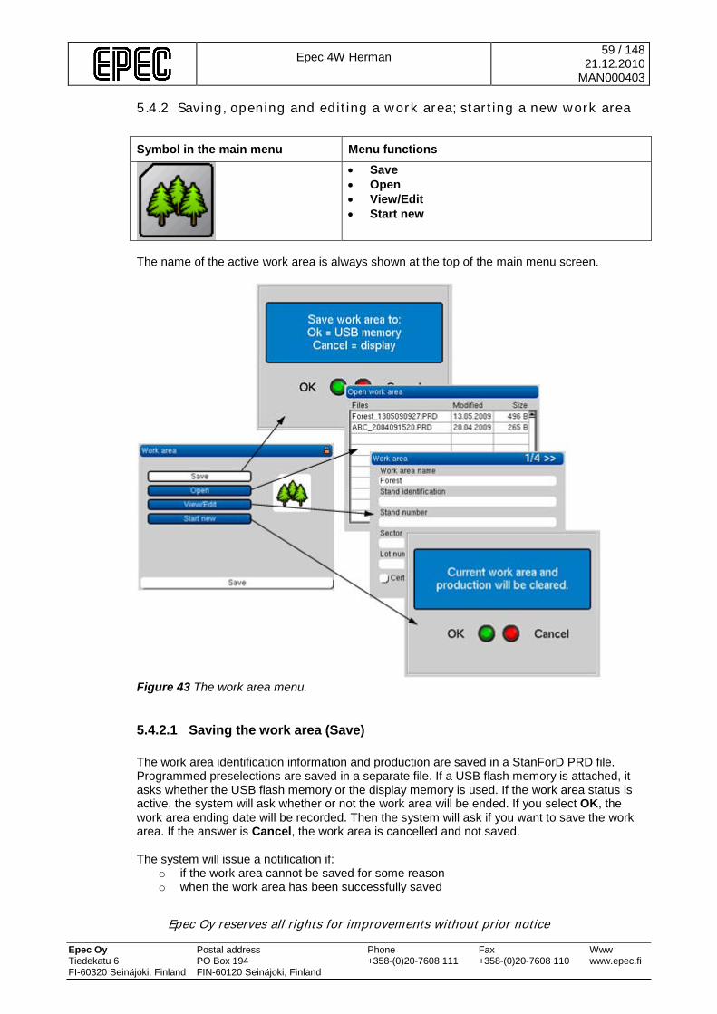
Epec 4W Herman
59 / 148 21.12.2010
MAN000403
Epec Oy reserves all rights for improvements without prior notice Epec Oy Postal address Phone Fax Www Tiedekatu 6 PO Box 194 +358-(0)20-7608 111 +358-(0)20-7608 110 www.epec.fi FI-60320 Seinäjoki, Finland FIN-60120 Seinäjoki, Finland
5.4.2 Saving, opening and editing a work area; starting a new work area Symbol in the main menu Menu functions
• Save • Open • View/Edit • Start new
The name of the active work area is always shown at the top of the main menu screen.
Figure 43 The work area menu.
5.4.2.1 Saving the work area (Save) The work area identification information and production are saved in a StanForD PRD file. Programmed preselections are saved in a separate file. If a USB flash memory is attached, it asks whether the USB flash memory or the display memory is used. If the work area status is active, the system will ask whether or not the work area will be ended. If you select OK, the work area ending date will be recorded. Then the system will ask if you want to save the work area. If the answer is Cancel, the work area is cancelled and not saved. The system will issue a notification if:
o if the work area cannot be saved for some reason o when the work area has been successfully saved
Epec 4W Herman
60 / 148 21.12.2010
MAN000403
Epec Oy reserves all rights for improvements without prior notice Epec Oy Postal address Phone Fax Www Tiedekatu 6 PO Box 194 +358-(0)20-7608 111 +358-(0)20-7608 110 www.epec.fi FI-60320 Seinäjoki, Finland FIN-60120 Seinäjoki, Finland
It is possible to save up to 30 work areas to the display. If the display is full and you try to save to the display, a message will inform you of this. However, it is still possible to save to the display. In this case, it will replace the oldest work area saved to the display. Work areas saved on the display can be copied from the Reports window to USB flash memory. After the work area is copied it is deleted from the display.
5.4.2.2 Opening a work area (Open) This button opens a screen showing the work areas saved to the display or in the USB flash memory drive. If the USB memory stick is not connected, the list shows the work areas saved to the display. To upload the information of a work area onscreen, select it from the list. The preselections used for the work area will also be uploaded. Completed work areas can also be opened, however, work (sawing) is blocked.
5.4.2.3 Editing work area information (show/edit) This button opens a screen in which you can set the work area information. The only mandatory information is the work area name (felling will not be possible if there is no work area name). Select the field you want to edit and press the green button on the programming wheel to open the virtual keyboard. Enter the information you want with the virtual keyboard and then select OK on the virtual keyboard. The Show/Edit screen is divided into four subscreens: Page 1: Work area information Page 2: Seller information Page 3: Buyer information and cutting method You can select the cutting method from a menu using the programming wheel:
• 1. Top tree removal • 2. First thinning • 3. Other thinning • 4. Clear felling • 5. Seed tree, protective tree or belt felling • 6. Felling to clear after a storm or wind damage • 7. Clearing a road, ditch, power line or other line • 8. Residential lot felling • 9. Other special felling type • 10. Clearing or tree stand clearing
Page 4: Additional information You can switch to another subscreen/page by selecting the “>>” button and pressing OK.
5.4.2.4 Starting a new work area (start new) This function will reset the work area information and production data from the display unit memory. Always save or print the information pertaining to a work area before starting a new one. The names of work areas cannot include any blanks.
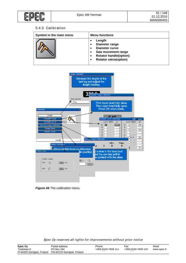
Epec 4W Herman
61 / 148 21.12.2010
MAN000403
Epec Oy reserves all rights for improvements without prior notice Epec Oy Postal address Phone Fax Www Tiedekatu 6 PO Box 194 +358-(0)20-7608 111 +358-(0)20-7608 110 www.epec.fi FI-60320 Seinäjoki, Finland FIN-60120 Seinäjoki, Finland
5.4.3 Calibration
Symbol in the main menu Menu functions
• Length • Diameter range • Diameter curve • Saw movement range • Rotator handle(option) • Rotator valve(option)
Figure 44 The calibration menu.

Epec 4W Herman
62 / 148 21.12.2010
MAN000403
Epec Oy reserves all rights for improvements without prior notice Epec Oy Postal address Phone Fax Www Tiedekatu 6 PO Box 194 +358-(0)20-7608 111 +358-(0)20-7608 110 www.epec.fi FI-60320 Seinäjoki, Finland FIN-60120 Seinäjoki, Finland
5.4.3.1 Length calibration 1. First select the tree species preselection in the Settings menu. Enter the Handling screen,
feed a sufficient length of wood and cut the log. Then remove the harvester head and manually measure the cut log.
2. Select Length in the Calibration menu. The length of the last cut log will be displayed:
Figure 45 Length calibration.
3. Length calibration is tree species specific. Select the tree species in the bottom left hand
corner. Go to the length figure adjustment screen by selecting OK. 4. Change the length using the programming wheel until the length is the same as the length
you manually measured. 5. When the length is the same as you measured, select OK. The system will ask you whether
or not you want to save the new calibration figure. Save the new length calibration figure by selecting OK.
5.4.3.2 Diameter range calibration To calibrate the diameter range: 1. Select Diameter range in the Calibration menu. 2. Open and close the harvester head a couple of times when prompted to do so by the
system until the pulse figure stabilises. 3. Save the value by selecting OK.
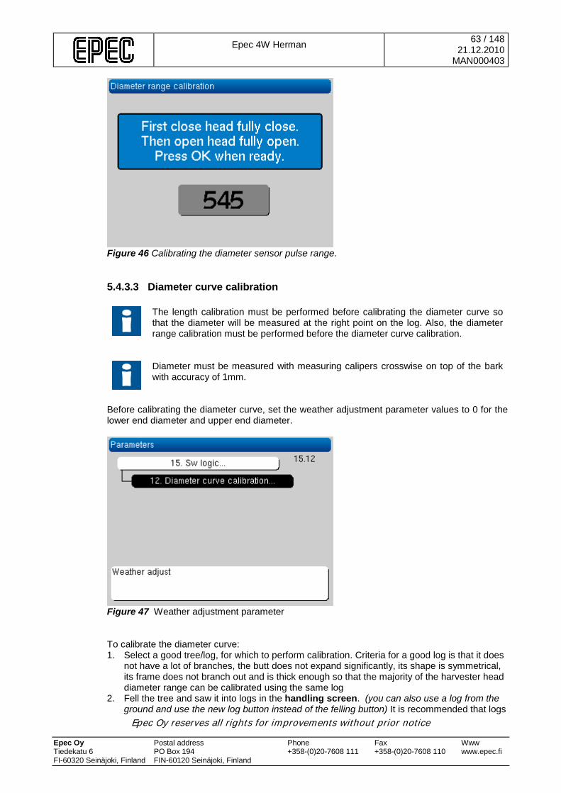
Epec 4W Herman
63 / 148 21.12.2010
MAN000403
Epec Oy reserves all rights for improvements without prior notice Epec Oy Postal address Phone Fax Www Tiedekatu 6 PO Box 194 +358-(0)20-7608 111 +358-(0)20-7608 110 www.epec.fi FI-60320 Seinäjoki, Finland FIN-60120 Seinäjoki, Finland
Figure 46 Calibrating the diameter sensor pulse range.
5.4.3.3 Diameter curve calibration
The length calibration must be performed before calibrating the diameter curve so that the diameter will be measured at the right point on the log. Also, the diameter range calibration must be performed before the diameter curve calibration.
Diameter must be measured with measuring calipers crosswise on top of the bark with accuracy of 1mm.
Before calibrating the diameter curve, set the weather adjustment parameter values to 0 for the lower end diameter and upper end diameter.
Figure 47 Weather adjustment parameter To calibrate the diameter curve: 1. Select a good tree/log, for which to perform calibration. Criteria for a good log is that it does
not have a lot of branches, the butt does not expand significantly, its shape is symmetrical, its frame does not branch out and is thick enough so that the majority of the harvester head diameter range can be calibrated using the same log
2. Fell the tree and saw it into logs in the handling screen. (you can also use a log from the ground and use the new log button instead of the felling button) It is recommended that logs
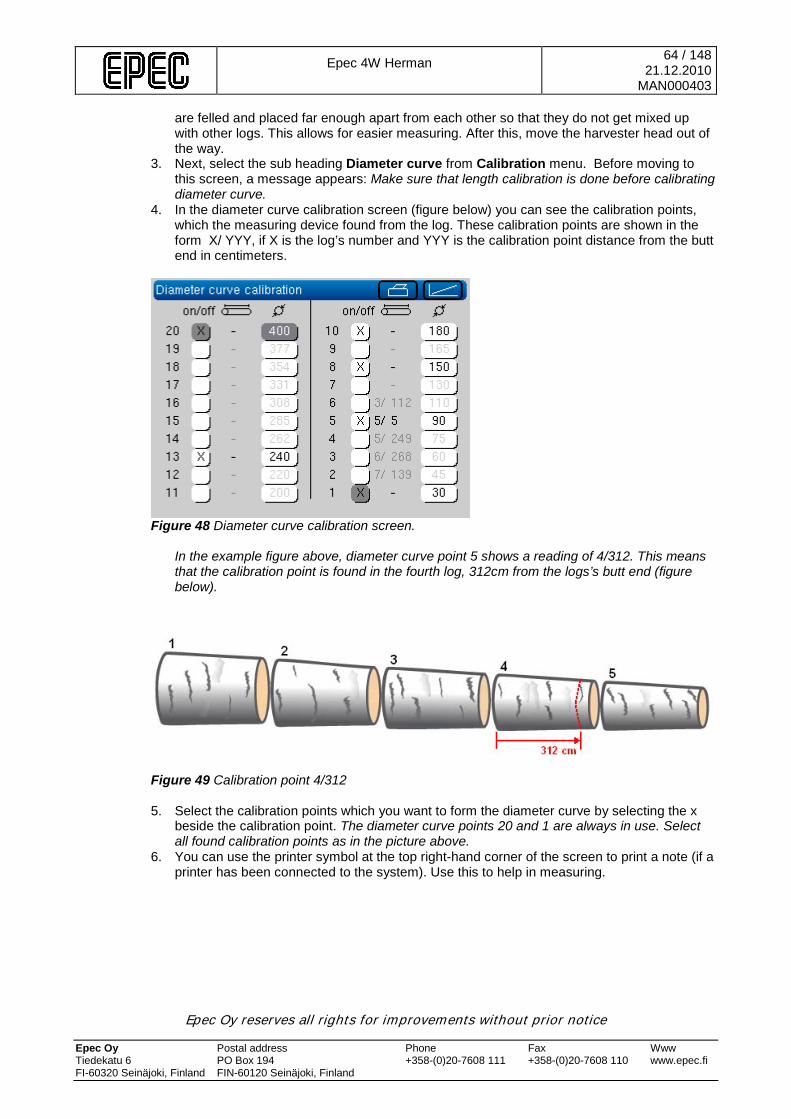
Epec 4W Herman
64 / 148 21.12.2010
MAN000403
Epec Oy reserves all rights for improvements without prior notice Epec Oy Postal address Phone Fax Www Tiedekatu 6 PO Box 194 +358-(0)20-7608 111 +358-(0)20-7608 110 www.epec.fi FI-60320 Seinäjoki, Finland FIN-60120 Seinäjoki, Finland
are felled and placed far enough apart from each other so that they do not get mixed up with other logs. This allows for easier measuring. After this, move the harvester head out of the way.
3. Next, select the sub heading Diameter curve from Calibration menu. Before moving to this screen, a message appears: Make sure that length calibration is done before calibrating diameter curve.
4. In the diameter curve calibration screen (figure below) you can see the calibration points, which the measuring device found from the log. These calibration points are shown in the form X/ YYY, if X is the log’s number and YYY is the calibration point distance from the butt end in centimeters.
Figure 48 Diameter curve calibration screen.
In the example figure above, diameter curve point 5 shows a reading of 4/312. This means that the calibration point is found in the fourth log, 312cm from the logs’s butt end (figure below).
Figure 49 Calibration point 4/312 5. Select the calibration points which you want to form the diameter curve by selecting the x
beside the calibration point. The diameter curve points 20 and 1 are always in use. Select all found calibration points as in the picture above.
6. You can use the printer symbol at the top right-hand corner of the screen to print a note (if a printer has been connected to the system). Use this to help in measuring.
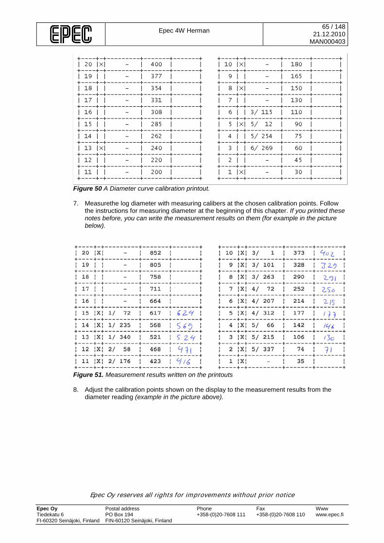
Epec 4W Herman
65 / 148 21.12.2010
MAN000403
Epec Oy reserves all rights for improvements without prior notice Epec Oy Postal address Phone Fax Www Tiedekatu 6 PO Box 194 +358-(0)20-7608 111 +358-(0)20-7608 110 www.epec.fi FI-60320 Seinäjoki, Finland FIN-60120 Seinäjoki, Finland
Figure 50 A Diameter curve calibration printout. 7. Measurethe log diameter with measuring calibers at the chosen calibration points. Follow
the instructions for measuring diameter at the beginning of this chapter. If you printed these notes before, you can write the measurement results on them (for example in the picture below).
Figure 51. Measurement results written on the printouts 8. Adjust the calibration points shown on the display to the measurement results from the
diameter reading (example in the picture above).
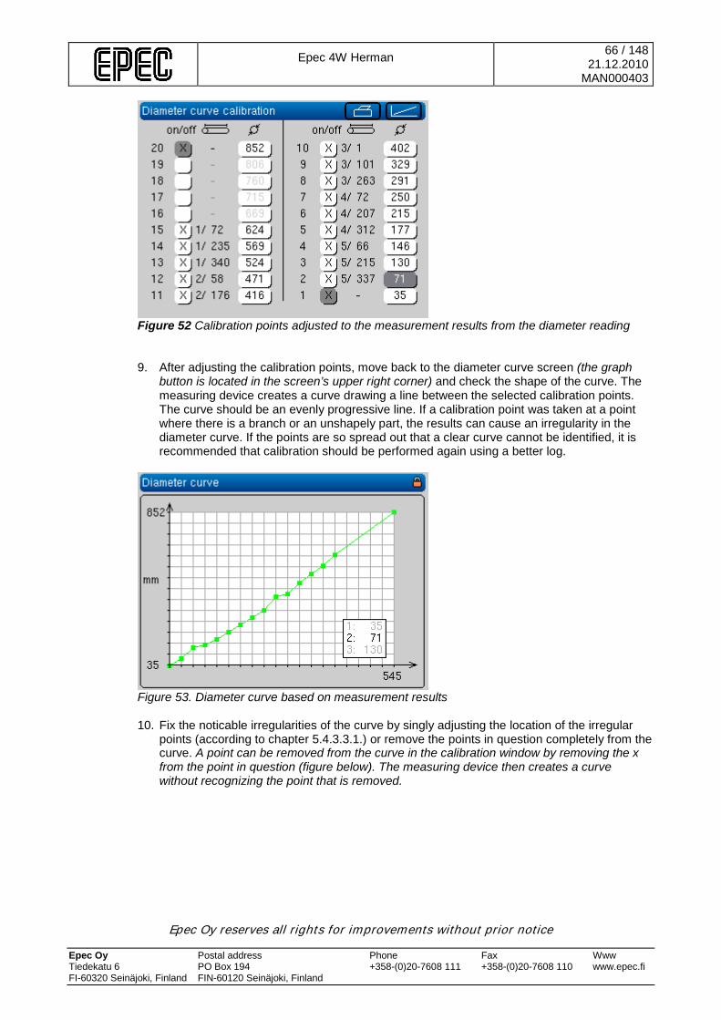
Epec 4W Herman
66 / 148 21.12.2010
MAN000403
Epec Oy reserves all rights for improvements without prior notice Epec Oy Postal address Phone Fax Www Tiedekatu 6 PO Box 194 +358-(0)20-7608 111 +358-(0)20-7608 110 www.epec.fi FI-60320 Seinäjoki, Finland FIN-60120 Seinäjoki, Finland
Figure 52 Calibration points adjusted to the measurement results from the diameter reading 9. After adjusting the calibration points, move back to the diameter curve screen (the graph
button is located in the screen’s upper right corner) and check the shape of the curve. The measuring device creates a curve drawing a line between the selected calibration points. The curve should be an evenly progressive line. If a calibration point was taken at a point where there is a branch or an unshapely part, the results can cause an irregularity in the diameter curve. If the points are so spread out that a clear curve cannot be identified, it is recommended that calibration should be performed again using a better log.
Figure 53. Diameter curve based on measurement results 10. Fix the noticable irregularities of the curve by singly adjusting the location of the irregular
points (according to chapter 5.4.3.3.1.) or remove the points in question completely from the curve. A point can be removed from the curve in the calibration window by removing the x from the point in question (figure below). The measuring device then creates a curve without recognizing the point that is removed.

Epec 4W Herman
67 / 148 21.12.2010
MAN000403
Epec Oy reserves all rights for improvements without prior notice Epec Oy Postal address Phone Fax Www Tiedekatu 6 PO Box 194 +358-(0)20-7608 111 +358-(0)20-7608 110 www.epec.fi FI-60320 Seinäjoki, Finland FIN-60120 Seinäjoki, Finland
Figure 54. Irregular calibration points removed
Figure 55. Diameter curve complete 11. When you are satisfied with the shape of the curve, you can exit the calibration screen. If
calibration was unsuccessful for the whole harvester head diameter area, calibration can be performed again using a different log. Fix the part of the curve which did not calibrate properly the first time.
12. Calibration is complete and you can continue to work. 13. Perform diameter calibration and check measurments regularly. If you find errors in the
calculations of the dimensions, fix the curve and calibrate again (also note weather adjustment).
5.4.3.3.1 Graphically editing the diameter curve In the right side upper corner of the diameter curve calibration screen is the graph button which activates a screen in which the diameter curve can be edited graphically. The X axis shows the number of diameter pulses. The minimum and maximum values define the harvester head’s diameter range based on calibration. The Y axis shows the diameter range in milimeters. The minimum and maximum values are defined by the diameter (points 1 and 20).
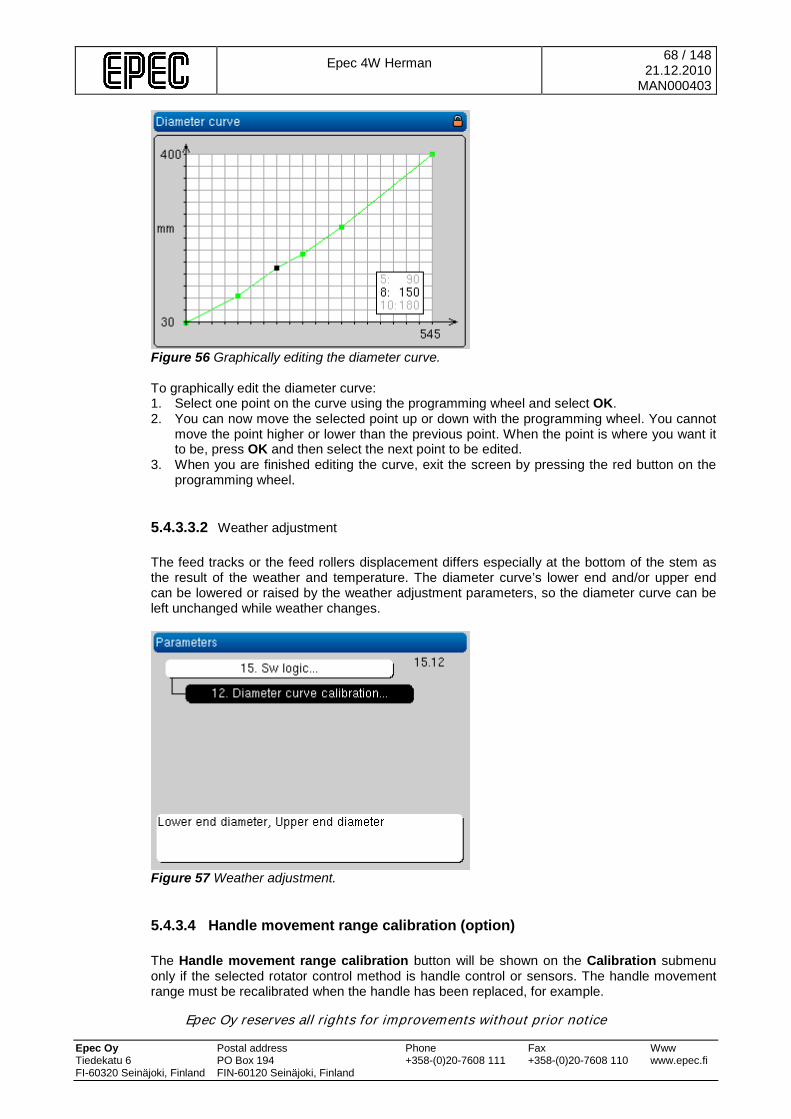
Epec 4W Herman
68 / 148 21.12.2010
MAN000403
Epec Oy reserves all rights for improvements without prior notice Epec Oy Postal address Phone Fax Www Tiedekatu 6 PO Box 194 +358-(0)20-7608 111 +358-(0)20-7608 110 www.epec.fi FI-60320 Seinäjoki, Finland FIN-60120 Seinäjoki, Finland
Figure 56 Graphically editing the diameter curve. To graphically edit the diameter curve: 1. Select one point on the curve using the programming wheel and select OK. 2. You can now move the selected point up or down with the programming wheel. You cannot
move the point higher or lower than the previous point. When the point is where you want it to be, press OK and then select the next point to be edited.
3. When you are finished editing the curve, exit the screen by pressing the red button on the programming wheel.
5.4.3.3.2 Weather adjustment The feed tracks or the feed rollers displacement differs especially at the bottom of the stem as the result of the weather and temperature. The diameter curve’s lower end and/or upper end can be lowered or raised by the weather adjustment parameters, so the diameter curve can be left unchanged while weather changes.
Figure 57 Weather adjustment.
5.4.3.4 Handle movement range calibration (option) The Handle movement range calibration button will be shown on the Calibration submenu only if the selected rotator control method is handle control or sensors. The handle movement range must be recalibrated when the handle has been replaced, for example.
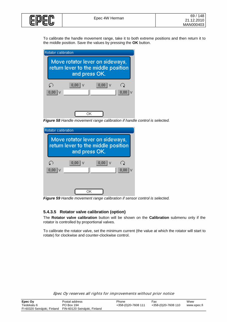
Epec 4W Herman
69 / 148 21.12.2010
MAN000403
Epec Oy reserves all rights for improvements without prior notice Epec Oy Postal address Phone Fax Www Tiedekatu 6 PO Box 194 +358-(0)20-7608 111 +358-(0)20-7608 110 www.epec.fi FI-60320 Seinäjoki, Finland FIN-60120 Seinäjoki, Finland
To calibrate the handle movement range, take it to both extreme positions and then return it to the middle position. Save the values by pressing the OK button.
Figure 58 Handle movement range calibration if handle control is selected.
Figure 59 Handle movement range calibration if sensor control is selected.
5.4.3.5 Rotator valve calibration (option) The Rotator valve calibration button will be shown on the Calibration submenu only if the rotator is controlled by proportional valves. To calibrate the rotator valve, set the minimum current (the value at which the rotator will start to rotate) for clockwise and counter-clockwise control.

Epec 4W Herman
70 / 148 21.12.2010
MAN000403
Epec Oy reserves all rights for improvements without prior notice Epec Oy Postal address Phone Fax Www Tiedekatu 6 PO Box 194 +358-(0)20-7608 111 +358-(0)20-7608 110 www.epec.fi FI-60320 Seinäjoki, Finland FIN-60120 Seinäjoki, Finland
Figure 60 Rotator valve calibration.
The rotator valve calibration is only allowed to do by the authorized maintenance personel.
5.4.3.6 Saw movement range calibration
The saw chain must be removed from the saw bar before calibrating the saw movement range.
To calibrate the saw movement range: 1. Select Saw movement range in the Calibration menu. 2. The saw chain needs to be removed, if rotating of the saw shain can not be stopped.
Figure 61 Has the saw chain been removed.
3. Grab a log with the harvester head and ensure that it has contact with the log (minimum
pulse calibration).

Epec 4W Herman
71 / 148 21.12.2010
MAN000403
Epec Oy reserves all rights for improvements without prior notice Epec Oy Postal address Phone Fax Www Tiedekatu 6 PO Box 194 +358-(0)20-7608 111 +358-(0)20-7608 110 www.epec.fi FI-60320 Seinäjoki, Finland FIN-60120 Seinäjoki, Finland
Figure 62 Minimum pulse calibration.
4. Open the harvester head and drop the log. Control the saw blade out until the mechanical
limit by pressing the Saw button. The measuring device saves the saw blade position as the maximum calibration point.
Figure 63 Maximum pulse calibration.
5. Save the calibration by pressing OK. If you want to retain the old values, select Cancel.
Figure 64 Accepting new values.
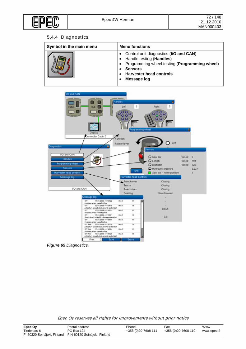
Epec 4W Herman
72 / 148 21.12.2010
MAN000403
Epec Oy reserves all rights for improvements without prior notice Epec Oy Postal address Phone Fax Www Tiedekatu 6 PO Box 194 +358-(0)20-7608 111 +358-(0)20-7608 110 www.epec.fi FI-60320 Seinäjoki, Finland FIN-60120 Seinäjoki, Finland
5.4.4 Diagnostics
Symbol in the main menu Menu functions
• Control unit diagnostics (I/O and CAN) • Handle testing (Handles) • Programming wheel testing (Programming wheel) • Sensors • Harvester head controls • Message log
Figure 65 Diagnostics.
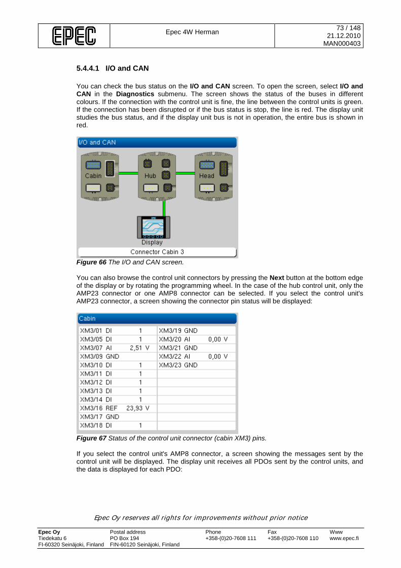
Epec 4W Herman
73 / 148 21.12.2010
MAN000403
Epec Oy reserves all rights for improvements without prior notice Epec Oy Postal address Phone Fax Www Tiedekatu 6 PO Box 194 +358-(0)20-7608 111 +358-(0)20-7608 110 www.epec.fi FI-60320 Seinäjoki, Finland FIN-60120 Seinäjoki, Finland
5.4.4.1 I/O and CAN You can check the bus status on the I/O and CAN screen. To open the screen, select I/O and CAN in the Diagnostics submenu. The screen shows the status of the buses in different colours. If the connection with the control unit is fine, the line between the control units is green. If the connection has been disrupted or if the bus status is stop, the line is red. The display unit studies the bus status, and if the display unit bus is not in operation, the entire bus is shown in red.
Figure 66 The I/O and CAN screen. You can also browse the control unit connectors by pressing the Next button at the bottom edge of the display or by rotating the programming wheel. In the case of the hub control unit, only the AMP23 connector or one AMP8 connector can be selected. If you select the control unit's AMP23 connector, a screen showing the connector pin status will be displayed:
Figure 67 Status of the control unit connector (cabin XM3) pins. If you select the control unit's AMP8 connector, a screen showing the messages sent by the control unit will be displayed. The display unit receives all PDOs sent by the control units, and the data is displayed for each PDO:

Epec 4W Herman
74 / 148 21.12.2010
MAN000403
Epec Oy reserves all rights for improvements without prior notice Epec Oy Postal address Phone Fax Www Tiedekatu 6 PO Box 194 +358-(0)20-7608 111 +358-(0)20-7608 110 www.epec.fi FI-60320 Seinäjoki, Finland FIN-60120 Seinäjoki, Finland
Figure 68 CAN messages or PDOs sent by the selected control unit.
5.4.4.2 Handles
When the Handles screen is active, pressing the handle buttons will not control the harvester head functions. This screen is for testing the buttons only.
The Handles screen shows data of buttons connected to the cabin control unit. To open the screen, select Handles in the Diagnostics submenu. • Preselections shows the number of the preselection button that is pressed. In the
preselection button picture, the selected button turns green. • Right shows the number of the button that is pressed on the right handle. • Left shows the number of the button that is pressed onthe left handle. • Function shows the function performed by the preselection button that has been pressed. • Rotator handle shows the position of the rotator handle (if the rotator handle is in use). The
beam should move right or left when you turn the handle.
Figure 69 The handle buttons.

Epec 4W Herman
75 / 148 21.12.2010
MAN000403
Epec Oy reserves all rights for improvements without prior notice Epec Oy Postal address Phone Fax Www Tiedekatu 6 PO Box 194 +358-(0)20-7608 111 +358-(0)20-7608 110 www.epec.fi FI-60320 Seinäjoki, Finland FIN-60120 Seinäjoki, Finland
5.4.4.3 Programming wheel In the Programming wheel screen, you can test the functionality of the programming wheel buttons and the rotation direction. To open the screen, select Programming wheel in the Diagnostics submenu. Test the functionality of the programming wheel’s buttons by pressing one button at a time:
• If the corresponding button in the diagnostics window turns green, the button is ok. • If the button does not turn green in the diagnostics window, there is an error in the
connection of the button (cable may be broken). • If a wrong button turns green in the diagnostics window when you press the button, the
cable for the button you pressed is connected to the wrong input of the cabin module. Check the electrical diagrams for the correct connection.
Test the functionality of the programming wheel rotation by turning it:
• If the rotation direction is shown as green in the diagnostics window, the programming wheel rotation is ok.
• If the neither direction turns green inthe diagnostics window, there is an error in the connection of the rotator (cable may be broken).
• If the wrong direction turns green when you turn the wheel, the signal wires (A and B chanel) are connected wrong to the cabin module. Check the electrical diagrams for the correct connection.
You can exit the Programming wheel screen by pressing the display's Back button.
Figure 70 Programming wheel testing.
5.4.4.4 Sensors The Sensors screen shows raw values sent by sensors connected to the harvester head control unit. To open the screen, select Sensors in the Diagnostics submenu.
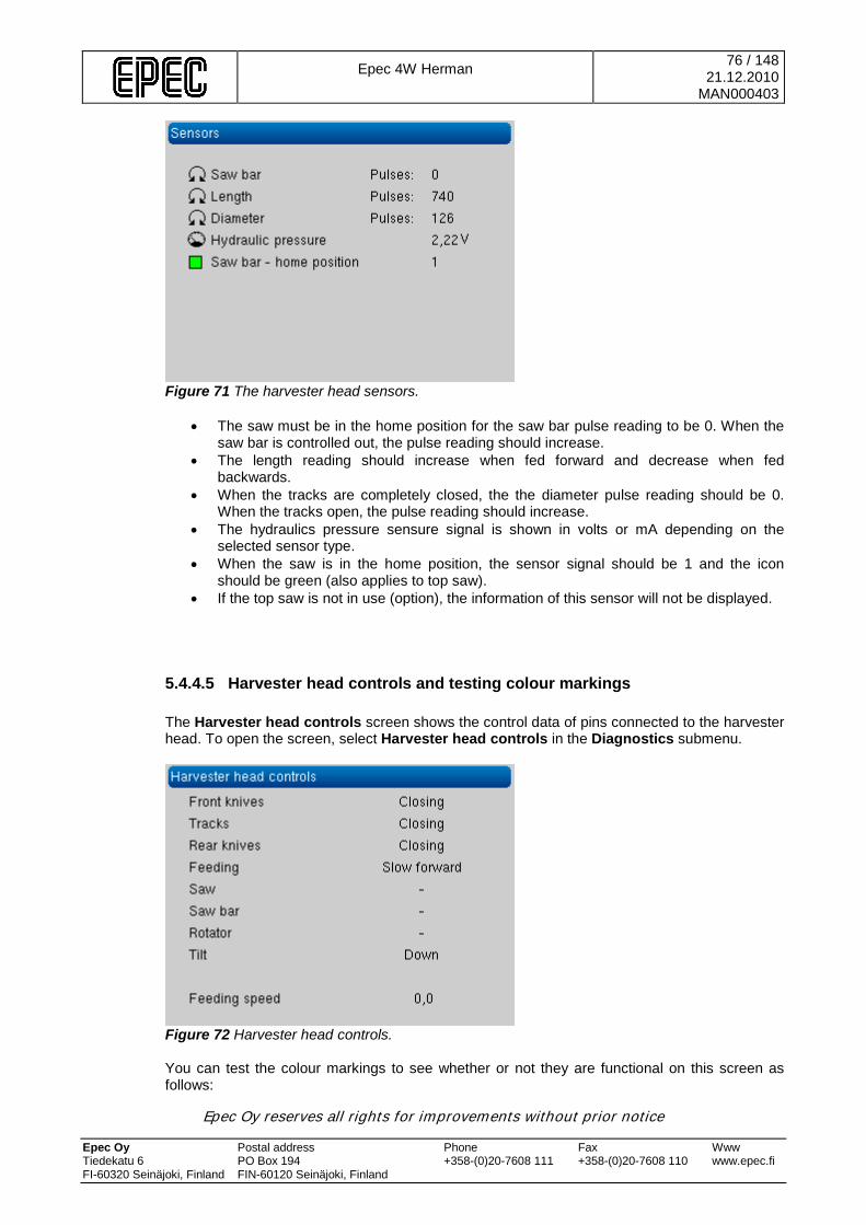
Epec 4W Herman
76 / 148 21.12.2010
MAN000403
Epec Oy reserves all rights for improvements without prior notice Epec Oy Postal address Phone Fax Www Tiedekatu 6 PO Box 194 +358-(0)20-7608 111 +358-(0)20-7608 110 www.epec.fi FI-60320 Seinäjoki, Finland FIN-60120 Seinäjoki, Finland
Figure 71 The harvester head sensors.
• The saw must be in the home position for the saw bar pulse reading to be 0. When the saw bar is controlled out, the pulse reading should increase.
• The length reading should increase when fed forward and decrease when fed backwards.
• When the tracks are completely closed, the the diameter pulse reading should be 0. When the tracks open, the pulse reading should increase.
• The hydraulics pressure sensure signal is shown in volts or mA depending on the selected sensor type.
• When the saw is in the home position, the sensor signal should be 1 and the icon should be green (also applies to top saw).
• If the top saw is not in use (option), the information of this sensor will not be displayed.
5.4.4.5 Harvester head controls and testing colour markings The Harvester head controls screen shows the control data of pins connected to the harvester head. To open the screen, select Harvester head controls in the Diagnostics submenu.
Figure 72 Harvester head controls.
You can test the colour markings to see whether or not they are functional on this screen as follows:
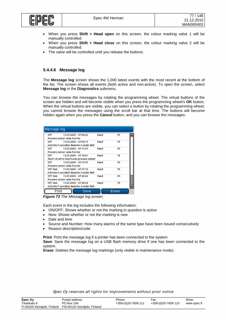
Epec 4W Herman
77 / 148 21.12.2010
MAN000403
Epec Oy reserves all rights for improvements without prior notice Epec Oy Postal address Phone Fax Www Tiedekatu 6 PO Box 194 +358-(0)20-7608 111 +358-(0)20-7608 110 www.epec.fi FI-60320 Seinäjoki, Finland FIN-60120 Seinäjoki, Finland
• When you press Shift + Head open on this screen, the colour marking valve 1 will be manually controlled.
• When you press Shift + Head close on this screen, the colour marking valve 2 will be manually controlled.
• The valve will be controlled until you release the buttons.
5.4.4.6 Message log The Message log screen shows the 1,000 latest events with the most recent at the bottom of the list. The screen shows all events (both active and non-active). To open the screen, select Message log in the Diagnostics submenu. You can browse the messages by rotating the programming wheel. The virtual buttons of the screen are hidden and will become visible when you press the programming wheel's OK button. When the virtual buttons are visible, you can select a button by rotating the programming wheel; you cannot browse the messages using the scroll bar at that time. The buttons will become hidden again when you press the Cancel button, and you can browse the messages.
Figure 73 The Message log screen. Each event in the log includes the following information: • ON/OFF: Shows whether or not the marking in question is active • New: Shows whether or not the marking is new • Date and time • Source and Number: How many alarms of the same type have been issued consecutively • Reason description/code Print: Print the message log if a printer has been connected to the system. Save: Save the message log on a USB flash memory drive if one has been connected to the system. Erase: Deletes the message log markings (only visible in maintenance mode).

Epec 4W Herman
78 / 148 21.12.2010
MAN000403
Epec Oy reserves all rights for improvements without prior notice Epec Oy Postal address Phone Fax Www Tiedekatu 6 PO Box 194 +358-(0)20-7608 111 +358-(0)20-7608 110 www.epec.fi FI-60320 Seinäjoki, Finland FIN-60120 Seinäjoki, Finland
5.4.5 Settings Symbol in the main menu Menu functions
• Parameters • Preselections • Tree species • Assortments • Display • Default settings • Software • Options There are more specific descriptions of these functions in the following chapters.
Figure 74 Settings.

Epec 4W Herman
79 / 148 21.12.2010
MAN000403
Epec Oy reserves all rights for improvements without prior notice Epec Oy Postal address Phone Fax Www Tiedekatu 6 PO Box 194 +358-(0)20-7608 111 +358-(0)20-7608 110 www.epec.fi FI-60320 Seinäjoki, Finland FIN-60120 Seinäjoki, Finland
5.4.5.1 Parameters When you press the Parameters button, a new screen will be displayed. The screen includes the following functions: • Squeeze pressure • Tilt pressure • Opening pulses • Knives vibration • Rotator • Pumps • Saw bar • Other parameters
Figure 75 The parameters.
5.4.5.1.1 Squeeze pressure This screen is used to adjust the front knives, tracks and rear knives pressure valve settings.
Figure 76 Adjusting pressures. The different pressure levels are used as follows: • Low pressure level is used when controlling the knives to close (no log in the harvester
head).
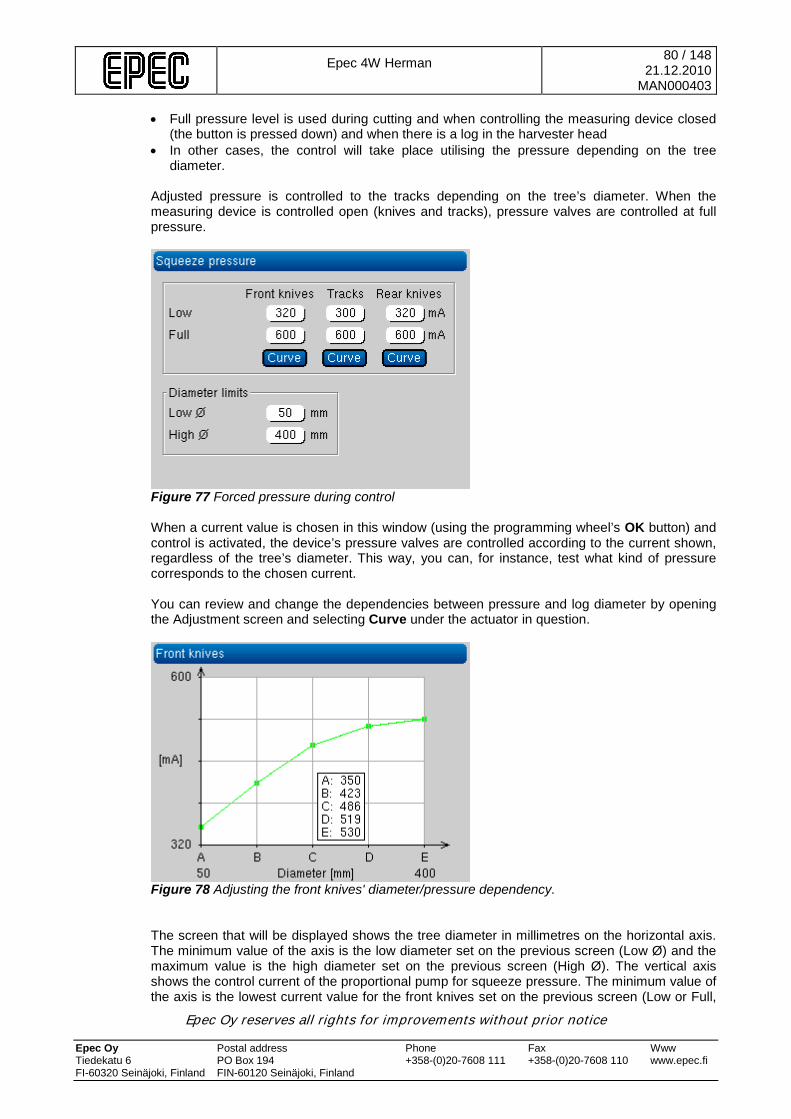
Epec 4W Herman
80 / 148 21.12.2010
MAN000403
Epec Oy reserves all rights for improvements without prior notice Epec Oy Postal address Phone Fax Www Tiedekatu 6 PO Box 194 +358-(0)20-7608 111 +358-(0)20-7608 110 www.epec.fi FI-60320 Seinäjoki, Finland FIN-60120 Seinäjoki, Finland
• Full pressure level is used during cutting and when controlling the measuring device closed (the button is pressed down) and when there is a log in the harvester head
• In other cases, the control will take place utilising the pressure depending on the tree diameter.
Adjusted pressure is controlled to the tracks depending on the tree’s diameter. When the measuring device is controlled open (knives and tracks), pressure valves are controlled at full pressure.
Figure 77 Forced pressure during control When a current value is chosen in this window (using the programming wheel’s OK button) and control is activated, the device’s pressure valves are controlled according to the current shown, regardless of the tree’s diameter. This way, you can, for instance, test what kind of pressure corresponds to the chosen current. You can review and change the dependencies between pressure and log diameter by opening the Adjustment screen and selecting Curve under the actuator in question.
Figure 78 Adjusting the front knives' diameter/pressure dependency. The screen that will be displayed shows the tree diameter in millimetres on the horizontal axis. The minimum value of the axis is the low diameter set on the previous screen (Low Ø) and the maximum value is the high diameter set on the previous screen (High Ø). The vertical axis shows the control current of the proportional pump for squeeze pressure. The minimum value of the axis is the lowest current value for the front knives set on the previous screen (Low or Full,

Epec 4W Herman
81 / 148 21.12.2010
MAN000403
Epec Oy reserves all rights for improvements without prior notice Epec Oy Postal address Phone Fax Www Tiedekatu 6 PO Box 194 +358-(0)20-7608 111 +358-(0)20-7608 110 www.epec.fi FI-60320 Seinäjoki, Finland FIN-60120 Seinäjoki, Finland
whichever is lower). The maximum value of the axis is the highest current value for the front knives set on the previous screen (Low or Full, which ever is higher). The highest and lowest diameter range difference (High Ø – Low Ø) is divided into four equal parts, and thus five points must be adjusted. In between these points, the pressure will be linearly adjusted based on the diameter. The points can be freely moved up or down on the screen in between the Low and Full pressure level values. If the diameter is greater then the specified high diameter, the higher diameter defined pressure is used. Comparably, if the diameter is smaller then the specified low diameter, the lower diameter defined pressure is used. There is a similar diameter/pressure dependency screen for the rear knives and the tracks.
5.4.5.1.2 Tilt pressure This screen is used to adjust the settings of the tilt pressure valves.
Figure 79 Squeeze pressure screen. When controlling the tilt down, tilt pressure is defined by the user set adjustment curve based on the tree’s diameter. Tilt is controlled down by the uset set constant pressure (high pressure up). When one of the direction current values are selected from the screen (by using the programming wheel’s OK button), and the down direction control is activated, the pressure valves are controlled according to the current shown, regardless of the tree’s diameter. This way, you can, for instance, test what kind of pressure corresponds to the chosen current. You can review and change the dependencies between pressure and log diameter by opening the Adjustment screen and selecting Curve under the actuator in question.
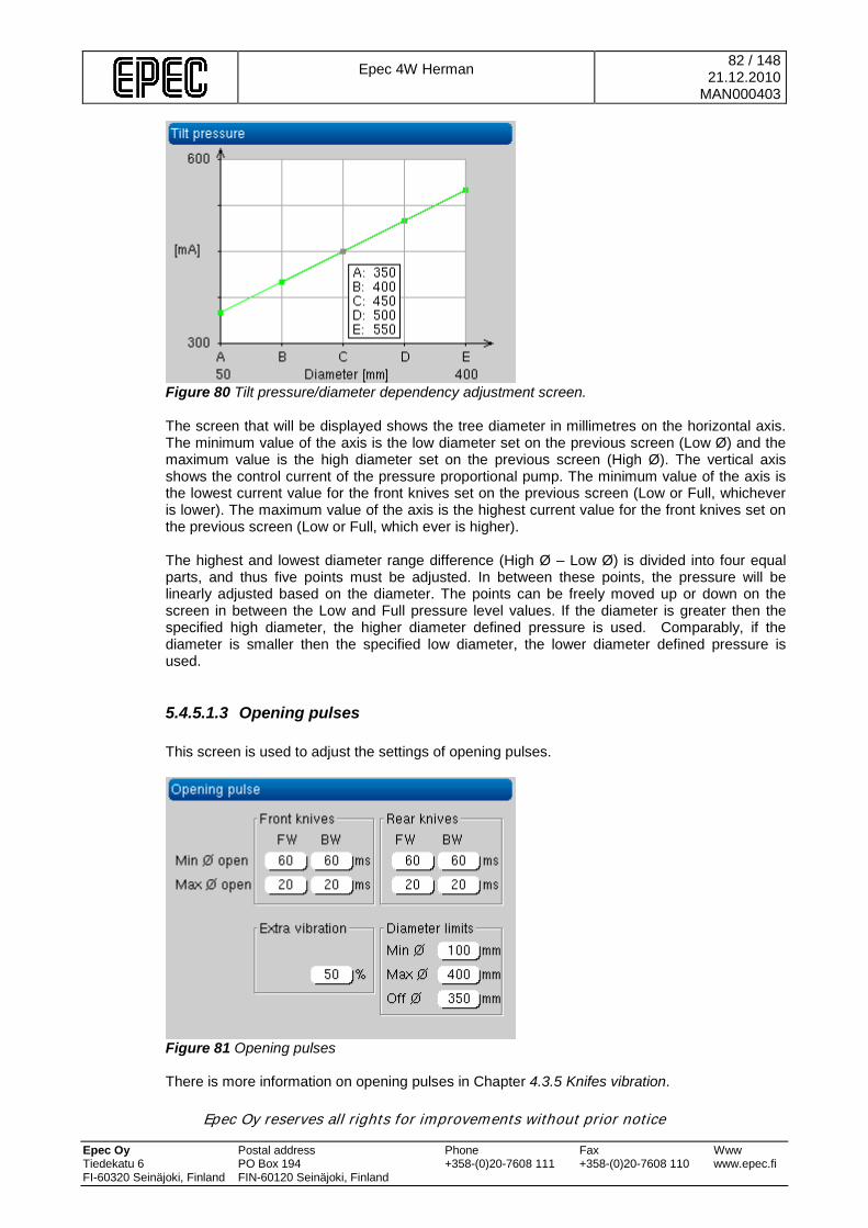
Epec 4W Herman
82 / 148 21.12.2010
MAN000403
Epec Oy reserves all rights for improvements without prior notice Epec Oy Postal address Phone Fax Www Tiedekatu 6 PO Box 194 +358-(0)20-7608 111 +358-(0)20-7608 110 www.epec.fi FI-60320 Seinäjoki, Finland FIN-60120 Seinäjoki, Finland
Figure 80 Tilt pressure/diameter dependency adjustment screen. The screen that will be displayed shows the tree diameter in millimetres on the horizontal axis. The minimum value of the axis is the low diameter set on the previous screen (Low Ø) and the maximum value is the high diameter set on the previous screen (High Ø). The vertical axis shows the control current of the pressure proportional pump. The minimum value of the axis is the lowest current value for the front knives set on the previous screen (Low or Full, whichever is lower). The maximum value of the axis is the highest current value for the front knives set on the previous screen (Low or Full, which ever is higher). The highest and lowest diameter range difference (High Ø – Low Ø) is divided into four equal parts, and thus five points must be adjusted. In between these points, the pressure will be linearly adjusted based on the diameter. The points can be freely moved up or down on the screen in between the Low and Full pressure level values. If the diameter is greater then the specified high diameter, the higher diameter defined pressure is used. Comparably, if the diameter is smaller then the specified low diameter, the lower diameter defined pressure is used.
5.4.5.1.3 Opening pulses This screen is used to adjust the settings of opening pulses.
Figure 81 Opening pulses There is more information on opening pulses in Chapter 4.3.5 Knifes vibration.
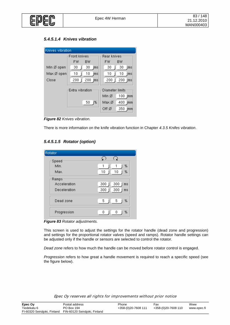
Epec 4W Herman
83 / 148 21.12.2010
MAN000403
Epec Oy reserves all rights for improvements without prior notice Epec Oy Postal address Phone Fax Www Tiedekatu 6 PO Box 194 +358-(0)20-7608 111 +358-(0)20-7608 110 www.epec.fi FI-60320 Seinäjoki, Finland FIN-60120 Seinäjoki, Finland
5.4.5.1.4 Knives vibration
Figure 82 Knives vibration. There is more information on the knife vibration function in Chapter 4.3.5 Knifes vibration.
5.4.5.1.5 Rotator (option)
Figure 83 Rotator adjustments. This screen is used to adjust the settings for the rotator handle (dead zone and progression) and settings for the proportional rotator valves (speed and ramps). Rotator handle settings can be adjusted only if the handle or sensors are selected to control the rotator. Dead zone refers to how much the handle can be moved before rotator control is engaged. Progression refers to how great a handle movement is required to reach a specific speed (see the figure below).
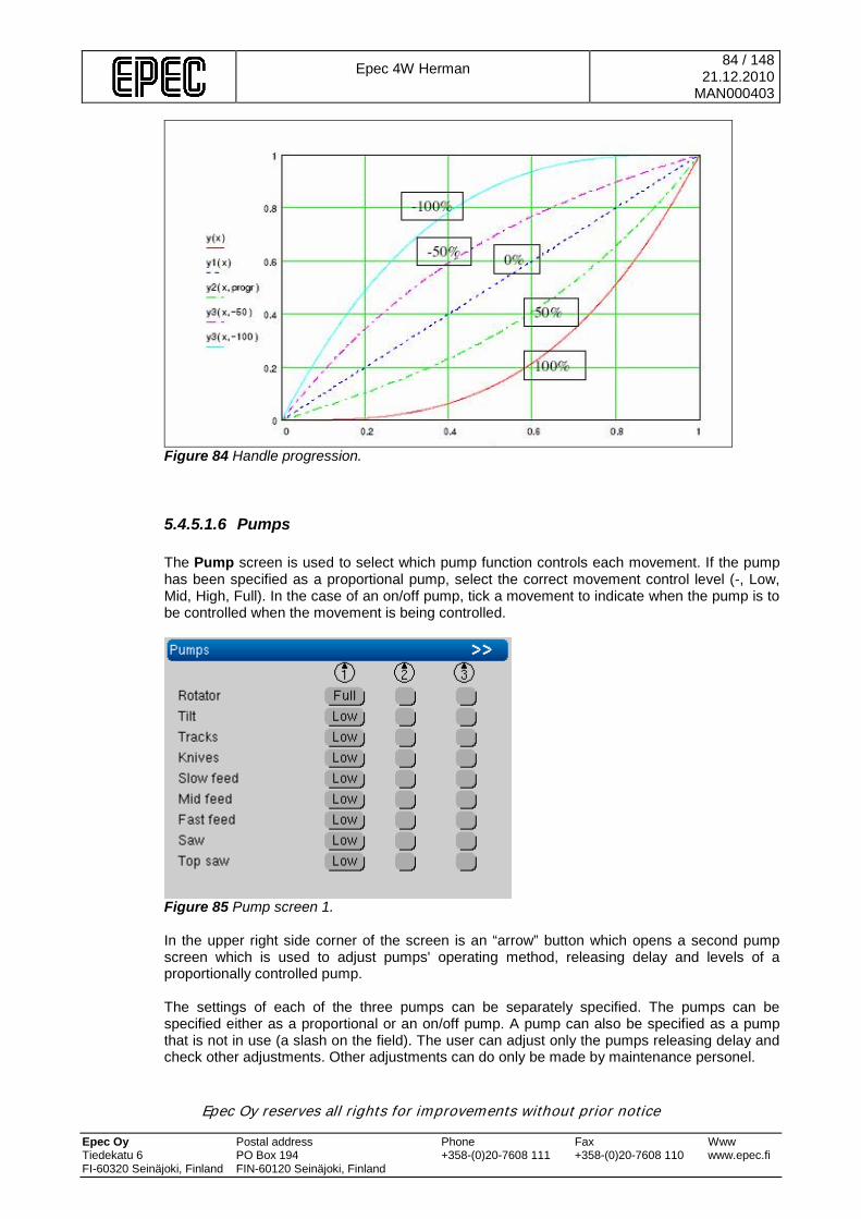
Epec 4W Herman
84 / 148 21.12.2010
MAN000403
Epec Oy reserves all rights for improvements without prior notice Epec Oy Postal address Phone Fax Www Tiedekatu 6 PO Box 194 +358-(0)20-7608 111 +358-(0)20-7608 110 www.epec.fi FI-60320 Seinäjoki, Finland FIN-60120 Seinäjoki, Finland
Figure 84 Handle progression.
5.4.5.1.6 Pumps The Pump screen is used to select which pump function controls each movement. If the pump has been specified as a proportional pump, select the correct movement control level (-, Low, Mid, High, Full). In the case of an on/off pump, tick a movement to indicate when the pump is to be controlled when the movement is being controlled.
Figure 85 Pump screen 1. In the upper right side corner of the screen is an “arrow” button which opens a second pump screen which is used to adjust pumps' operating method, releasing delay and levels of a proportionally controlled pump. The settings of each of the three pumps can be separately specified. The pumps can be specified either as a proportional or an on/off pump. A pump can also be specified as a pump that is not in use (a slash on the field). The user can adjust only the pumps releasing delay and check other adjustments. Other adjustments can do only be made by maintenance personel.
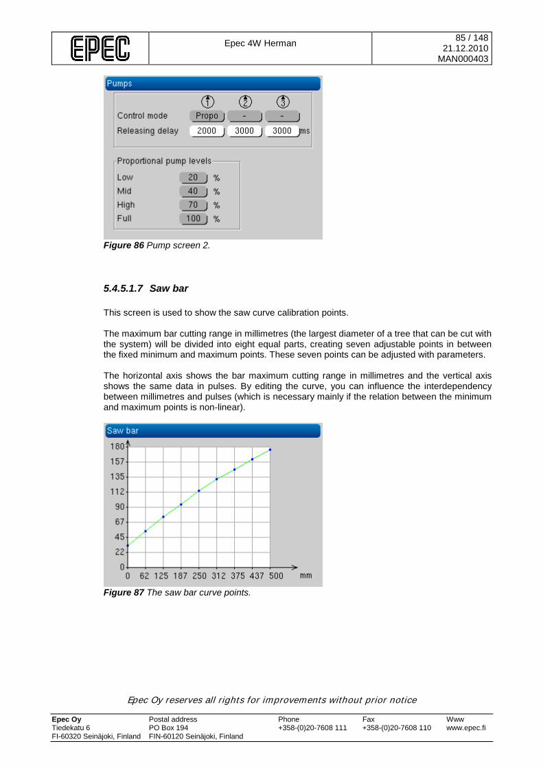
Epec 4W Herman
85 / 148 21.12.2010
MAN000403
Epec Oy reserves all rights for improvements without prior notice Epec Oy Postal address Phone Fax Www Tiedekatu 6 PO Box 194 +358-(0)20-7608 111 +358-(0)20-7608 110 www.epec.fi FI-60320 Seinäjoki, Finland FIN-60120 Seinäjoki, Finland
Figure 86 Pump screen 2.
5.4.5.1.7 Saw bar This screen is used to show the saw curve calibration points. The maximum bar cutting range in millimetres (the largest diameter of a tree that can be cut with the system) will be divided into eight equal parts, creating seven adjustable points in between the fixed minimum and maximum points. These seven points can be adjusted with parameters. The horizontal axis shows the bar maximum cutting range in millimetres and the vertical axis shows the same data in pulses. By editing the curve, you can influence the interdependency between millimetres and pulses (which is necessary mainly if the relation between the minimum and maximum points is non-linear).
Figure 87 The saw bar curve points.
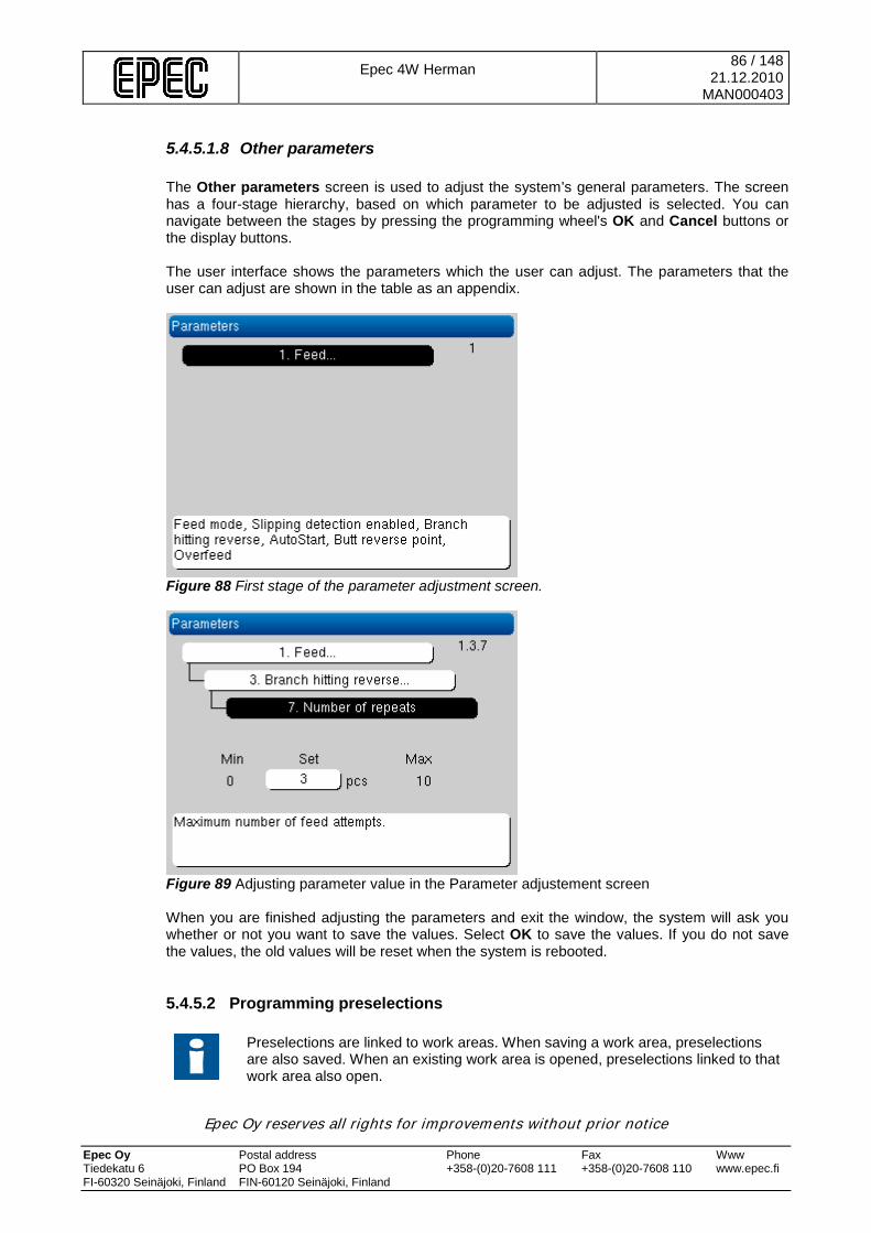
Epec 4W Herman
86 / 148 21.12.2010
MAN000403
Epec Oy reserves all rights for improvements without prior notice Epec Oy Postal address Phone Fax Www Tiedekatu 6 PO Box 194 +358-(0)20-7608 111 +358-(0)20-7608 110 www.epec.fi FI-60320 Seinäjoki, Finland FIN-60120 Seinäjoki, Finland
5.4.5.1.8 Other parameters The Other parameters screen is used to adjust the system’s general parameters. The screen has a four-stage hierarchy, based on which parameter to be adjusted is selected. You can navigate between the stages by pressing the programming wheel's OK and Cancel buttons or the display buttons. The user interface shows the parameters which the user can adjust. The parameters that the user can adjust are shown in the table as an appendix.
Figure 88 First stage of the parameter adjustment screen.
Figure 89 Adjusting parameter value in the Parameter adjustement screen When you are finished adjusting the parameters and exit the window, the system will ask you whether or not you want to save the values. Select OK to save the values. If you do not save the values, the old values will be reset when the system is rebooted.
5.4.5.2 Programming preselections
Preselections are linked to work areas. When saving a work area, preselections are also saved. When an existing work area is opened, preselections linked to that work area also open.
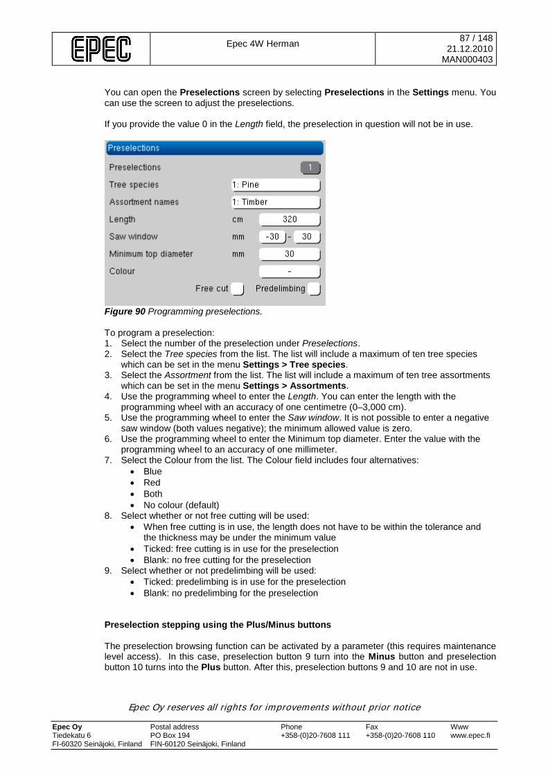
Epec 4W Herman
87 / 148 21.12.2010
MAN000403
Epec Oy reserves all rights for improvements without prior notice Epec Oy Postal address Phone Fax Www Tiedekatu 6 PO Box 194 +358-(0)20-7608 111 +358-(0)20-7608 110 www.epec.fi FI-60320 Seinäjoki, Finland FIN-60120 Seinäjoki, Finland
You can open the Preselections screen by selecting Preselections in the Settings menu. You can use the screen to adjust the preselections. If you provide the value 0 in the Length field, the preselection in question will not be in use.
Figure 90 Programming preselections.
To program a preselection: 1. Select the number of the preselection under Preselections. 2. Select the Tree species from the list. The list will include a maximum of ten tree species
which can be set in the menu Settings > Tree species. 3. Select the Assortment from the list. The list will include a maximum of ten tree assortments
which can be set in the menu Settings > Assortments. 4. Use the programming wheel to enter the Length. You can enter the length with the
programming wheel with an accuracy of one centimetre (0–3,000 cm). 5. Use the programming wheel to enter the Saw window. It is not possible to enter a negative
saw window (both values negative); the minimum allowed value is zero. 6. Use the programming wheel to enter the Minimum top diameter. Enter the value with the
programming wheel to an accuracy of one millimeter. 7. Select the Colour from the list. The Colour field includes four alternatives:
• Blue • Red • Both • No colour (default)
8. Select whether or not free cutting will be used: • When free cutting is in use, the length does not have to be within the tolerance and
the thickness may be under the minimum value • Ticked: free cutting is in use for the preselection • Blank: no free cutting for the preselection
9. Select whether or not predelimbing will be used: • Ticked: predelimbing is in use for the preselection • Blank: no predelimbing for the preselection
Preselection stepping using the Plus/Minus buttons The preselection browsing function can be activated by a parameter (this requires maintenance level access). In this case, preselection button 9 turn into the Minus button and preselection button 10 turns into the Plus button. After this, preselection buttons 9 and 10 are not in use.
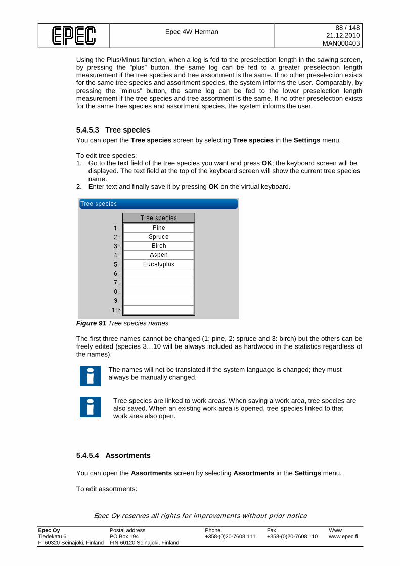
Epec 4W Herman
88 / 148 21.12.2010
MAN000403
Epec Oy reserves all rights for improvements without prior notice Epec Oy Postal address Phone Fax Www Tiedekatu 6 PO Box 194 +358-(0)20-7608 111 +358-(0)20-7608 110 www.epec.fi FI-60320 Seinäjoki, Finland FIN-60120 Seinäjoki, Finland
Using the Plus/Minus function, when a log is fed to the preselection length in the sawing screen, by pressing the ”plus” button, the same log can be fed to a greater preselection length measurement if the tree species and tree assortment is the same. If no other preselection exists for the same tree species and assortment species, the system informs the user. Comparably, by pressing the ”minus” button, the same log can be fed to the lower preselection length measurement if the tree species and tree assortment is the same. If no other preselection exists for the same tree species and assortment species, the system informs the user.
5.4.5.3 Tree species You can open the Tree species screen by selecting Tree species in the Settings menu. To edit tree species: 1. Go to the text field of the tree species you want and press OK; the keyboard screen will be
displayed. The text field at the top of the keyboard screen will show the current tree species name.
2. Enter text and finally save it by pressing OK on the virtual keyboard.
Figure 91 Tree species names. The first three names cannot be changed (1: pine, 2: spruce and 3: birch) but the others can be freely edited (species 3…10 will be always included as hardwood in the statistics regardless of the names).
The names will not be translated if the system language is changed; they must always be manually changed.
Tree species are linked to work areas. When saving a work area, tree species are also saved. When an existing work area is opened, tree species linked to that work area also open.
5.4.5.4 Assortments You can open the Assortments screen by selecting Assortments in the Settings menu. To edit assortments:

Epec 4W Herman
89 / 148 21.12.2010
MAN000403
Epec Oy reserves all rights for improvements without prior notice Epec Oy Postal address Phone Fax Www Tiedekatu 6 PO Box 194 +358-(0)20-7608 111 +358-(0)20-7608 110 www.epec.fi FI-60320 Seinäjoki, Finland FIN-60120 Seinäjoki, Finland
1. Go to the text field of the assortment you want and press OK; the keyboard screen will be displayed. The text field at the top of the keyboard screen will show the current assortment name.
2. Enter text and finally save it by pressing OK on the virtual keyboard.
Figure 92 Assortment names.
The names will not be translated if the system language is changed; they must always be manually changed.
Assortments are linked to work areas. When saving a work area, assortments are also saved. When an existing work area is opened, assortments linked to that work area also open.
5.4.5.5 Display settings You can open the Display settings screen by selecting Display settings in the Settings menu. You can adjust the following settings: • Brightness: The display brightness can be adjusted between 0 and 18. • Language • Date • Time • Unit: The available alternatives are metric (metres, centimetres, millimetres, etc.) or imperial
(feet, inches, etc.). • Night mode: Changes the handling screen colours to darker.
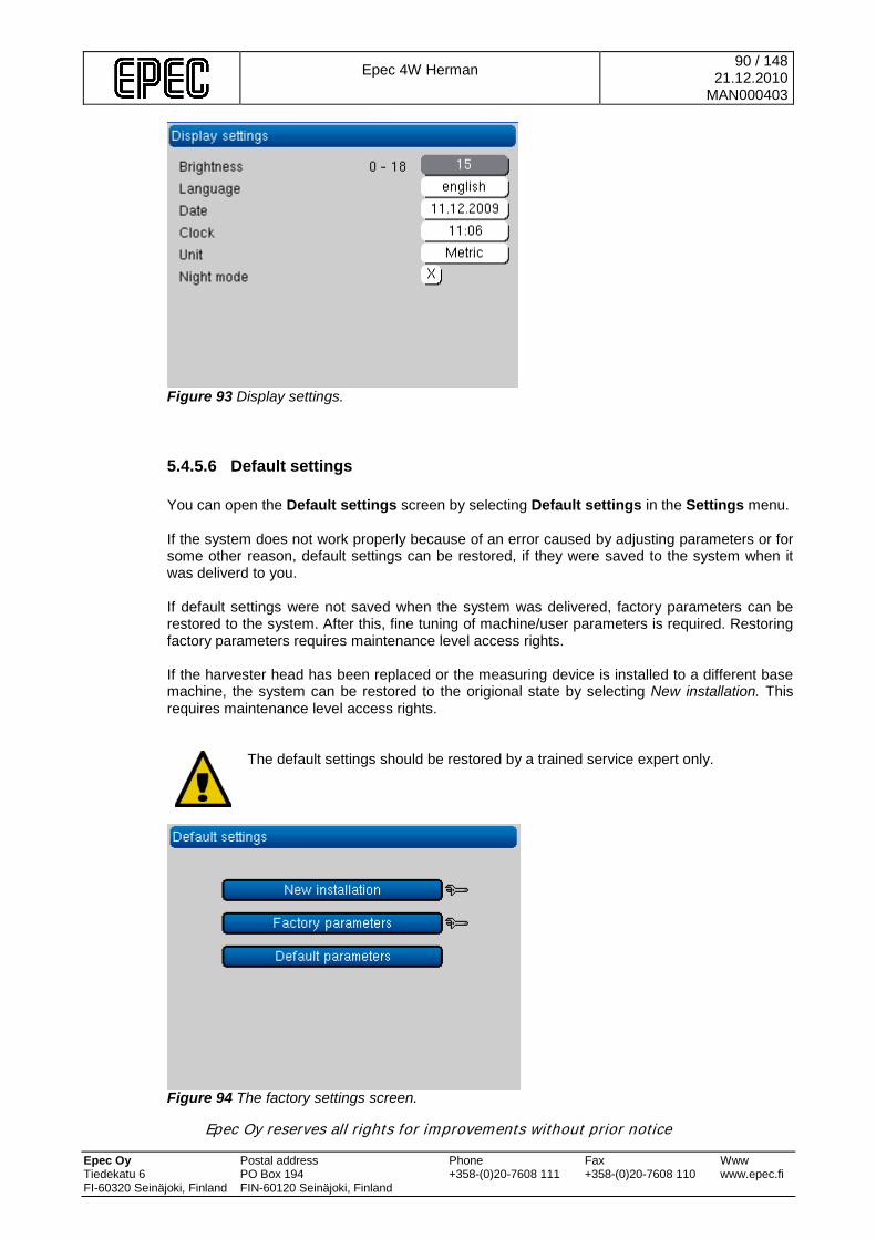
Epec 4W Herman
90 / 148 21.12.2010
MAN000403
Epec Oy reserves all rights for improvements without prior notice Epec Oy Postal address Phone Fax Www Tiedekatu 6 PO Box 194 +358-(0)20-7608 111 +358-(0)20-7608 110 www.epec.fi FI-60320 Seinäjoki, Finland FIN-60120 Seinäjoki, Finland
Figure 93 Display settings.
5.4.5.6 Default settings You can open the Default settings screen by selecting Default settings in the Settings menu. If the system does not work properly because of an error caused by adjusting parameters or for some other reason, default settings can be restored, if they were saved to the system when it was deliverd to you. If default settings were not saved when the system was delivered, factory parameters can be restored to the system. After this, fine tuning of machine/user parameters is required. Restoring factory parameters requires maintenance level access rights. If the harvester head has been replaced or the measuring device is installed to a different base machine, the system can be restored to the origional state by selecting New installation. This requires maintenance level access rights.
The default settings should be restored by a trained service expert only.
Figure 94 The factory settings screen.
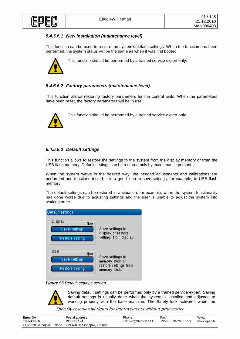
Epec 4W Herman
91 / 148 21.12.2010
MAN000403
Epec Oy reserves all rights for improvements without prior notice Epec Oy Postal address Phone Fax Www Tiedekatu 6 PO Box 194 +358-(0)20-7608 111 +358-(0)20-7608 110 www.epec.fi FI-60320 Seinäjoki, Finland FIN-60120 Seinäjoki, Finland
5.4.5.6.1 New installation (maintenance level) This function can be used to restore the system's default settings. When the function has been performed, the system status will be the same as when it was first booted.
This function should be performed by a trained service expert only.
5.4.5.6.2 Factory parameters (maintenance level) This function allows restoring factory parameters for the control units. When the parameters have been reset, the factory parameters will be in use.
This function should be performed by a trained service expert only.
5.4.5.6.3 Default settings This function allows to restore the settings to the system from the display memory or from the USB flash memory. Default settings can be restored only by maintenance personel. When the system works in the desired way, the needed adjustments and calibrations are performed and functions tested, it is a good idea to save settings, for example, to USB flash memory. The default settings can be restored in a situation, for example, when the system functionality has gone worse due to adjusting settings and the user is unable to adjust the system into working order.
Figure 95 Default settings screen.
Saving default settings can be performed only by a trained service expert. Saving default settings is usually done when the system is installed and adjusted to working properly with the base machine. The Safety lock activates when the

Epec 4W Herman
92 / 148 21.12.2010
MAN000403
Epec Oy reserves all rights for improvements without prior notice Epec Oy Postal address Phone Fax Www Tiedekatu 6 PO Box 194 +358-(0)20-7608 111 +358-(0)20-7608 110 www.epec.fi FI-60320 Seinäjoki, Finland FIN-60120 Seinäjoki, Finland
default settings are restored.
Figure 96 Default setting files. It is also possible to restore default settings, from another system, if the harvester head is the same. Before restoring default settings from another system, a notification is shown stating the difference in machine number. At this point, restoring can also be canceled.
Figure 97 Difference in the machine number.
5.4.5.7 Software You can open the Software screen by selecting Software in the Settings menu.
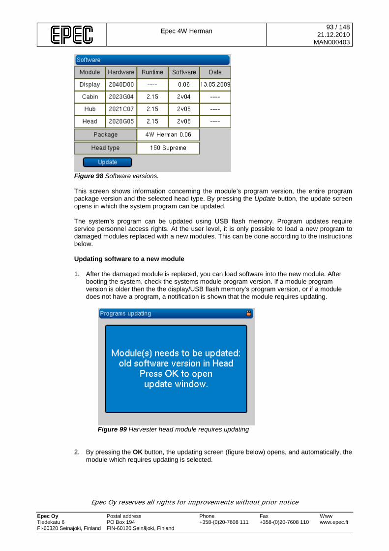
Epec 4W Herman
93 / 148 21.12.2010
MAN000403
Epec Oy reserves all rights for improvements without prior notice Epec Oy Postal address Phone Fax Www Tiedekatu 6 PO Box 194 +358-(0)20-7608 111 +358-(0)20-7608 110 www.epec.fi FI-60320 Seinäjoki, Finland FIN-60120 Seinäjoki, Finland
Figure 98 Software versions. This screen shows information concerning the module’s program version, the entire program package version and the selected head type. By pressing the Update button, the update screen opens in which the system program can be updated. The system’s program can be updated using USB flash memory. Program updates require service personnel access rights. At the user level, it is only possible to load a new program to damaged modules replaced with a new modules. This can be done according to the instructions below. Updating software to a new module 1. After the damaged module is replaced, you can load software into the new module. After
booting the system, check the systems module program version. If a module program version is older then the the display/USB flash memory’s program version, or if a module does not have a program, a notification is shown that the module requires updating.
Figure 99 Harvester head module requires updating
2. By pressing the OK button, the updating screen (figure below) opens, and automatically, the
module which requires updating is selected.
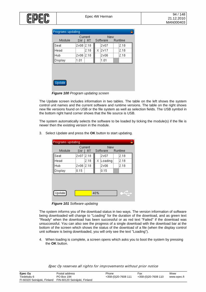
Epec 4W Herman
94 / 148 21.12.2010
MAN000403
Epec Oy reserves all rights for improvements without prior notice Epec Oy Postal address Phone Fax Www Tiedekatu 6 PO Box 194 +358-(0)20-7608 111 +358-(0)20-7608 110 www.epec.fi FI-60320 Seinäjoki, Finland FIN-60120 Seinäjoki, Finland
Figure 100 Program updating screen
The Update screen includes information in two tables. The table on the left shows the system control unit names and the current software and runtime versions. The table on the right shows new file versions found on USB or the file system as well as selection fields. The USB symbol in the bottom right hand corner shows that the file source is USB. The system automatically selects the software to be loaded by ticking the module(s) if the file is newer then the existing version in the module. 3. Select Update and press the OK button to start updating.
Figure 101 Software updating
The system informs you of the download status in two ways. The version information of software being downloaded will change to "Loading" for the duration of the download, and as green text "Ready" when the download has been successful or as red text "Failed" if the download was unsuccessful. You can also see the progress of a single download with the download bar at the bottom of the screen which shows the status of the download of a file (when the display control unit software is being downloaded, you will only see the text "Loading"). 4. When loading is complete, a screen opens which asks you to boot the system by pressing
the OK button.
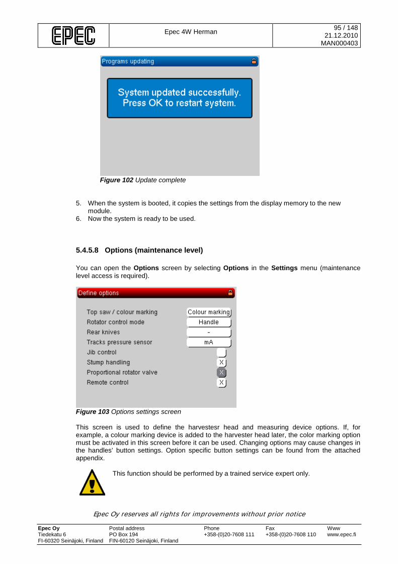
Epec 4W Herman
95 / 148 21.12.2010
MAN000403
Epec Oy reserves all rights for improvements without prior notice Epec Oy Postal address Phone Fax Www Tiedekatu 6 PO Box 194 +358-(0)20-7608 111 +358-(0)20-7608 110 www.epec.fi FI-60320 Seinäjoki, Finland FIN-60120 Seinäjoki, Finland
Figure 102 Update complete
5. When the system is booted, it copies the settings from the display memory to the new
module. 6. Now the system is ready to be used.
5.4.5.8 Options (maintenance level) You can open the Options screen by selecting Options in the Settings menu (maintenance level access is required).
Figure 103 Options settings screen This screen is used to define the harvestesr head and measuring device options. If, for example, a colour marking device is added to the harvester head later, the color marking option must be activated in this screen before it can be used. Changing options may cause changes in the handles’ button settings. Option specific button settings can be found from the attached appendix.
This function should be performed by a trained service expert only.
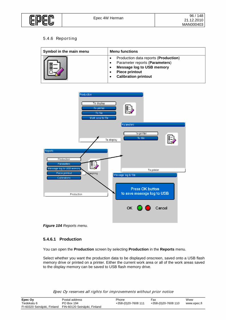
Epec 4W Herman
96 / 148 21.12.2010
MAN000403
Epec Oy reserves all rights for improvements without prior notice Epec Oy Postal address Phone Fax Www Tiedekatu 6 PO Box 194 +358-(0)20-7608 111 +358-(0)20-7608 110 www.epec.fi FI-60320 Seinäjoki, Finland FIN-60120 Seinäjoki, Finland
5.4.6 Reporting
Symbol in the main menu Menu functions
• Production data reports (Production) • Parameter reports (Parameters) • Message log to USB memory • Piece printout • Calibration printout
Figure 104 Reports menu.
5.4.6.1 Production You can open the Production screen by selecting Production in the Reports menu. Select whether you want the production data to be displayed onscreen, saved onto a USB flash memory drive or printed on a printer. Either the current work area or all of the work areas saved to the display memory can be saved to USB flash memory drive.
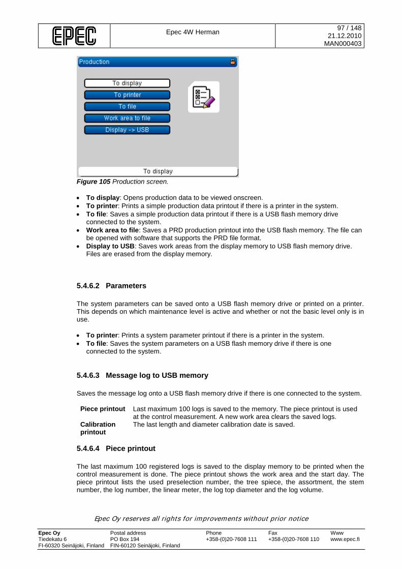
Epec 4W Herman
97 / 148 21.12.2010
MAN000403
Epec Oy reserves all rights for improvements without prior notice Epec Oy Postal address Phone Fax Www Tiedekatu 6 PO Box 194 +358-(0)20-7608 111 +358-(0)20-7608 110 www.epec.fi FI-60320 Seinäjoki, Finland FIN-60120 Seinäjoki, Finland
Figure 105 Production screen. • To display: Opens production data to be viewed onscreen. • To printer: Prints a simple production data printout if there is a printer in the system. • To file: Saves a simple production data printout if there is a USB flash memory drive
connected to the system. • Work area to file: Saves a PRD production printout into the USB flash memory. The file can
be opened with software that supports the PRD file format. • Display to USB: Saves work areas from the display memory to USB flash memory drive.
Files are erased from the display memory.
5.4.6.2 Parameters The system parameters can be saved onto a USB flash memory drive or printed on a printer. This depends on which maintenance level is active and whether or not the basic level only is in use. • To printer: Prints a system parameter printout if there is a printer in the system. • To file: Saves the system parameters on a USB flash memory drive if there is one
connected to the system.
5.4.6.3 Message log to USB memory Saves the message log onto a USB flash memory drive if there is one connected to the system. Piece printout Last maximum 100 logs is saved to the memory. The piece printout is used
at the control measurement. A new work area clears the saved logs. Calibration printout
The last length and diameter calibration date is saved.
5.4.6.4 Piece printout The last maximum 100 registered logs is saved to the display memory to be printed when the control measurement is done. The piece printout shows the work area and the start day. The piece printout lists the used preselection number, the tree spiece, the assortment, the stem number, the log number, the linear meter, the log top diameter and the log volume.

Epec 4W Herman
98 / 148 21.12.2010
MAN000403
Epec Oy reserves all rights for improvements without prior notice Epec Oy Postal address Phone Fax Www Tiedekatu 6 PO Box 194 +358-(0)20-7608 111 +358-(0)20-7608 110 www.epec.fi FI-60320 Seinäjoki, Finland FIN-60120 Seinäjoki, Finland
To ticking the Reports screen Sampling selection, a marker is set to the piece printout where can be seen where the sample logging is started. To stop the sample logging, remove the tick of the Sampling selection.
Starting of a new work area clears the registered logs.
First try to print the Calibration report. If this does not work, save the calibration report to USB memory if one is connected to the system.
Figure 106 The piece printout.
5.4.6.5 Calibration printout Calibration values used for length and diameter measuring, and the latest calibration dates can be printed. The system registeres the latest calibration date and this is shown on the printout. For each calibration of tree species, an adjustment date is saved seperately.
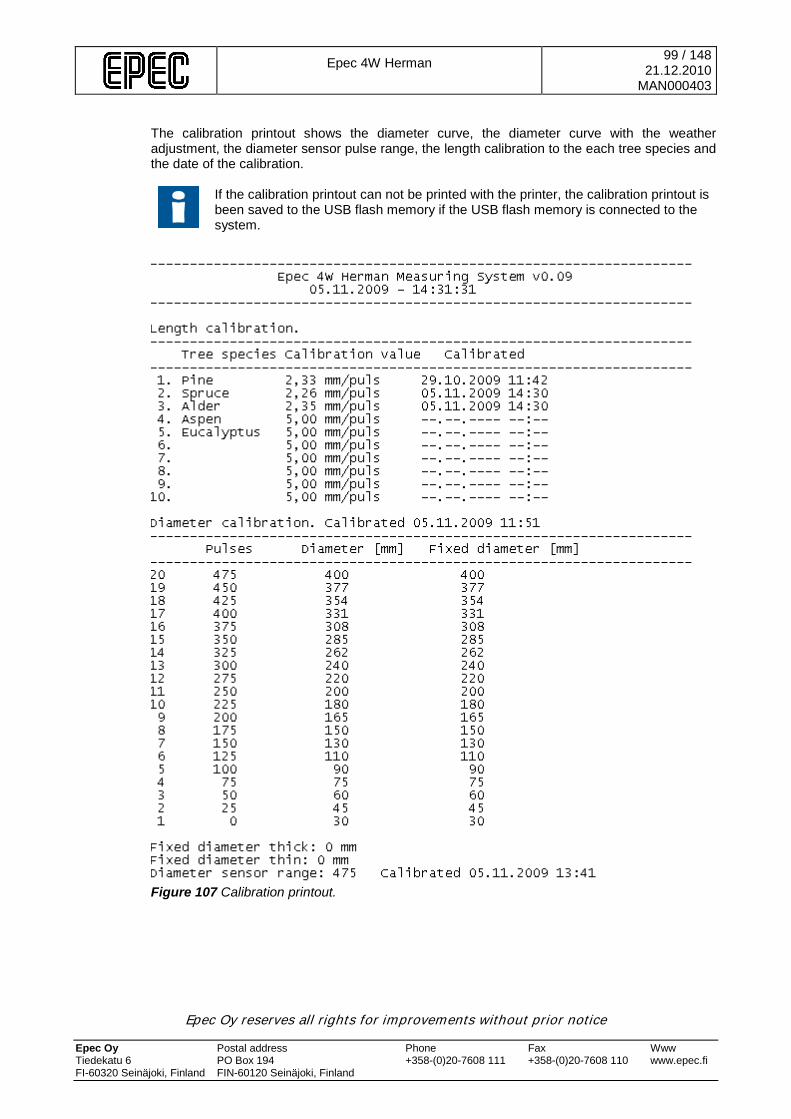
Epec 4W Herman
99 / 148 21.12.2010
MAN000403
Epec Oy reserves all rights for improvements without prior notice Epec Oy Postal address Phone Fax Www Tiedekatu 6 PO Box 194 +358-(0)20-7608 111 +358-(0)20-7608 110 www.epec.fi FI-60320 Seinäjoki, Finland FIN-60120 Seinäjoki, Finland
The calibration printout shows the diameter curve, the diameter curve with the weather adjustment, the diameter sensor pulse range, the length calibration to the each tree species and the date of the calibration.
If the calibration printout can not be printed with the printer, the calibration printout is been saved to the USB flash memory if the USB flash memory is connected to the system.
Figure 107 Calibration printout.
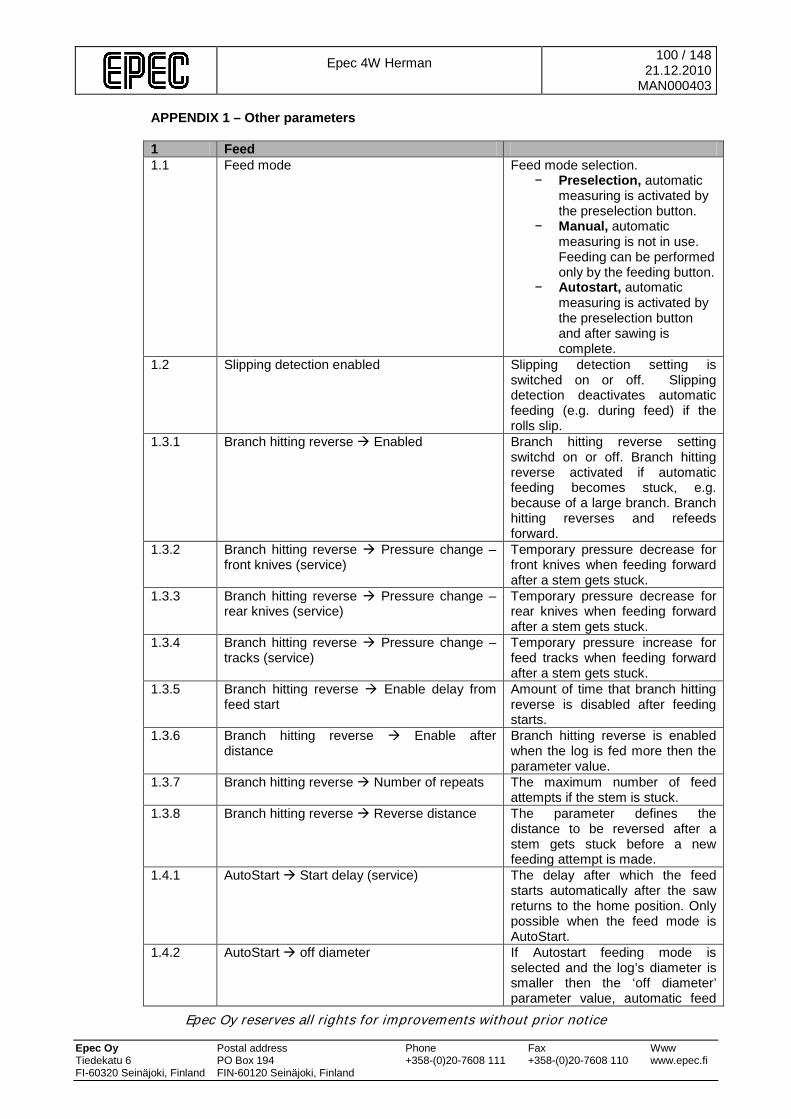
Epec 4W Herman
100 / 148 21.12.2010
MAN000403
Epec Oy reserves all rights for improvements without prior notice Epec Oy Postal address Phone Fax Www Tiedekatu 6 PO Box 194 +358-(0)20-7608 111 +358-(0)20-7608 110 www.epec.fi FI-60320 Seinäjoki, Finland FIN-60120 Seinäjoki, Finland
APPENDIX 1 – Other parameters 1 Feed 1.1 Feed mode Feed mode selection.
− Preselection, automatic measuring is activated by the preselection button.
− Manual, automatic measuring is not in use. Feeding can be performed only by the feeding button.
− Autostart, automatic measuring is activated by the preselection button and after sawing is complete.
1.2 Slipping detection enabled Slipping detection setting is switched on or off. Slipping detection deactivates automatic feeding (e.g. during feed) if the rolls slip.
1.3.1 Branch hitting reverse Enabled Branch hitting reverse setting switchd on or off. Branch hitting reverse activated if automatic feeding becomes stuck, e.g. because of a large branch. Branch hitting reverses and refeeds forward.
1.3.2 Branch hitting reverse Pressure change –front knives (service)
Temporary pressure decrease for front knives when feeding forward after a stem gets stuck.
1.3.3 Branch hitting reverse Pressure change – rear knives (service)
Temporary pressure decrease for rear knives when feeding forward after a stem gets stuck.
1.3.4 Branch hitting reverse Pressure change – tracks (service)
Temporary pressure increase for feed tracks when feeding forward after a stem gets stuck.
1.3.5 Branch hitting reverse Enable delay from feed start
Amount of time that branch hitting reverse is disabled after feeding starts.
1.3.6 Branch hitting reverse Enable after distance
Branch hitting reverse is enabled when the log is fed more then the parameter value.
1.3.7 Branch hitting reverse Number of repeats The maximum number of feed attempts if the stem is stuck.
1.3.8 Branch hitting reverse Reverse distance The parameter defines the distance to be reversed after a stem gets stuck before a new feeding attempt is made.
1.4.1 AutoStart Start delay (service) The delay after which the feed starts automatically after the saw returns to the home position. Only possible when the feed mode is AutoStart.
1.4.2 AutoStart off diameter If Autostart feeding mode is selected and the log’s diameter is smaller then the ‘off diameter’ parameter value, automatic feed

Epec 4W Herman
101 / 148 21.12.2010
MAN000403
Epec Oy reserves all rights for improvements without prior notice Epec Oy Postal address Phone Fax Www Tiedekatu 6 PO Box 194 +358-(0)20-7608 111 +358-(0)20-7608 110 www.epec.fi FI-60320 Seinäjoki, Finland FIN-60120 Seinäjoki, Finland
does not start after sawing. 1.5 Butt delimbing measure Point to which reversed for butt
delimbing function. 1.6 Braking before min top diameter (service) When the difference between the
diameter and minimum top diameter is below the parameter value, the feed speed is reduced to mid speed.
1.7.1 Predelimbing Distance Defines how much of the target length is exceeded during predelimbing before feeding to the target measure.
1.8 Valve step delay (service) The feed valves control interval during autofeed start
2 Saw 2.1 Saw mode Saw mode selection
− Manual, the saw bar returns when the saw button is released or when the saw has reached the target position
− Automatic, the saw bar returns only when the saw has reached the target position even if the saw button is released
2.2.1 Over sawing Relative when felling Relative oversawing when felling specifies, as a percentage, how far the saw bar is controlled over the target position.
2.2.2 Over sawing Absolute when felling Absolute oversawing when felling specifies, in milimeters, how far the saw bar is controlled over the target position. If relative oversawing is also in use, it is calculated first.
2.2.3 Over sawing Relative when cutting Relative oversawing when cutting specifies, as a percentage, how far the saw bar is controlled over the target position.
2.2.4 Over sawing Absolute when cutting Absolute oversawing when cutting specifies, in milimieters, how far the saw bar is controlled over the target position. If relative oversawing is also in use, it is calculated first.
2.3 Surface of log (service) Saw position in pulses when the chain contacts the surface of the log.
2.4 Outer mechanical limit (service) Saw position in pulses when the saw reaches its outer mechanical limit.
2.5.1 Saw chain change position limit (service) Saw bar position when the saw controlling stops automatically during chain change operation.
2.5.2 Saw chain change time limit (service) Time limit for saw controlling during chain change operation.
2.5.3 Saw chain change Saw bar out off delay Time that the saw bar is controlled
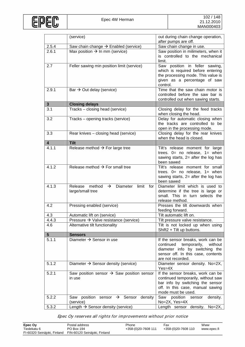
Epec 4W Herman
102 / 148 21.12.2010
MAN000403
Epec Oy reserves all rights for improvements without prior notice Epec Oy Postal address Phone Fax Www Tiedekatu 6 PO Box 194 +358-(0)20-7608 111 +358-(0)20-7608 110 www.epec.fi FI-60320 Seinäjoki, Finland FIN-60120 Seinäjoki, Finland
(service) out during chain change operation, after pumps are off.
2.5.4 Saw chain change Enabled (service) Saw chain change in use. 2.6.1 Max position In mm (service) Saw position in milimeters, when it
is controlled to the mechanical limit.
2.7 Feller sawing min position limit (service) Saw position in feller sawing, which is required before entering the processing mode. This value is given as a percentage of saw control.
2.9.1 Bar Out delay (service) Time that the saw chain motor is controlled before the saw bar is controlled out when sawing starts.
3 Closing delays 3.1 Tracks – closing head (service) Closing delay for the feed tracks
when closing the head. 3.2 Tracks – opening tracks (service) Delay for automatic closing when
the tracks are controlled to be open in the processing mode.
3.3 Rear knives – closing head (service) Closing delay for the rear knives when the head is closed.
4 Tilt 4.1.1 Release method For large tree Tilt’s release moment for large
trees. 0= no release, 1= when sawing starts, 2= after the log has been sawed
4.1.2 Release method For small tree Tilt’s release moment for small trees. 0= no release, 1= when sawing starts, 2= after the log has been sawed
4.1.3 Release method Diameter limit for large/small tree
Diameter limit which is used to determine if the tree is large or small. This in turn selects the release method.
4.2 Pressing enabled (service) Presses the tilt downwards when feeding forward.
4.3 Automatic lift on (service) Tilt automatic lift on. 4.4.3 Pressure Valve resistance (service) Tilt pressure valve resistance. 4.6 Alternative tilt functionality Tilt is not locked up when using
Shift2 + Tilt up buttons. 5 Sensors 5.1.1 Diameter Sensor in use If the sensor breaks, work can be
continued temporarily, without diameter info by switching the sensor off. In this case, contents are not recorded.
5.1.2 Diameter Sensor density (service) Diameter sensor density. No=2X, Yes=4X
5.2.1 Saw position sensor Saw position sensor in use
If the sensor breaks, work can be continued temporarily, without saw bar info by switching the sensor off. In this case, manual sawing mode must be used.
5.2.2 Saw position sensor Sensor density (service)
Saw position sensor density. No=2X, Yes=4X
5.3.2 Length Sensor density (service) Length sensor density. No=2X,
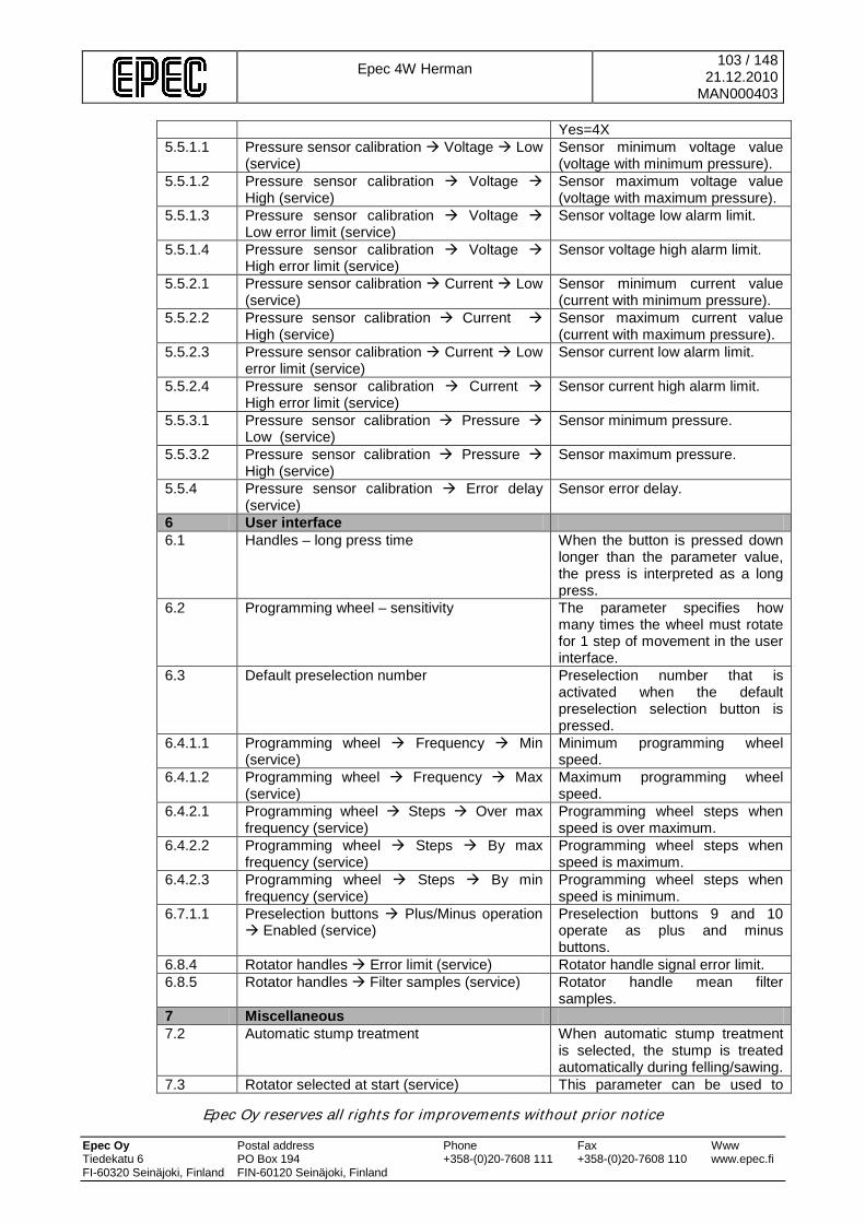
Epec 4W Herman
103 / 148 21.12.2010
MAN000403
Epec Oy reserves all rights for improvements without prior notice Epec Oy Postal address Phone Fax Www Tiedekatu 6 PO Box 194 +358-(0)20-7608 111 +358-(0)20-7608 110 www.epec.fi FI-60320 Seinäjoki, Finland FIN-60120 Seinäjoki, Finland
Yes=4X 5.5.1.1 Pressure sensor calibration Voltage Low
(service) Sensor minimum voltage value (voltage with minimum pressure).
5.5.1.2 Pressure sensor calibration Voltage High (service)
Sensor maximum voltage value (voltage with maximum pressure).
5.5.1.3 Pressure sensor calibration Voltage Low error limit (service)
Sensor voltage low alarm limit.
5.5.1.4 Pressure sensor calibration Voltage High error limit (service)
Sensor voltage high alarm limit.
5.5.2.1 Pressure sensor calibration Current Low (service)
Sensor minimum current value (current with minimum pressure).
5.5.2.2 Pressure sensor calibration Current High (service)
Sensor maximum current value (current with maximum pressure).
5.5.2.3 Pressure sensor calibration Current Low error limit (service)
Sensor current low alarm limit.
5.5.2.4 Pressure sensor calibration Current High error limit (service)
Sensor current high alarm limit.
5.5.3.1 Pressure sensor calibration Pressure Low (service)
Sensor minimum pressure.
5.5.3.2 Pressure sensor calibration Pressure High (service)
Sensor maximum pressure.
5.5.4 Pressure sensor calibration Error delay (service)
Sensor error delay.
6 User interface 6.1 Handles – long press time When the button is pressed down
longer than the parameter value, the press is interpreted as a long press.
6.2 Programming wheel – sensitivity The parameter specifies how many times the wheel must rotate for 1 step of movement in the user interface.
6.3 Default preselection number Preselection number that is activated when the default preselection selection button is pressed.
6.4.1.1 Programming wheel Frequency Min (service)
Minimum programming wheel speed.
6.4.1.2 Programming wheel Frequency Max (service)
Maximum programming wheel speed.
6.4.2.1 Programming wheel Steps Over max frequency (service)
Programming wheel steps when speed is over maximum.
6.4.2.2 Programming wheel Steps By max frequency (service)
Programming wheel steps when speed is maximum.
6.4.2.3 Programming wheel Steps By min frequency (service)
Programming wheel steps when speed is minimum.
6.7.1.1 Preselection buttons Plus/Minus operation Enabled (service)
Preselection buttons 9 and 10 operate as plus and minus buttons.
6.8.4 Rotator handles Error limit (service) Rotator handle signal error limit. 6.8.5 Rotator handles Filter samples (service) Rotator handle mean filter
samples. 7 Miscellaneous 7.2 Automatic stump treatment When automatic stump treatment
is selected, the stump is treated automatically during felling/sawing.
7.3 Rotator selected at start (service) This parameter can be used to
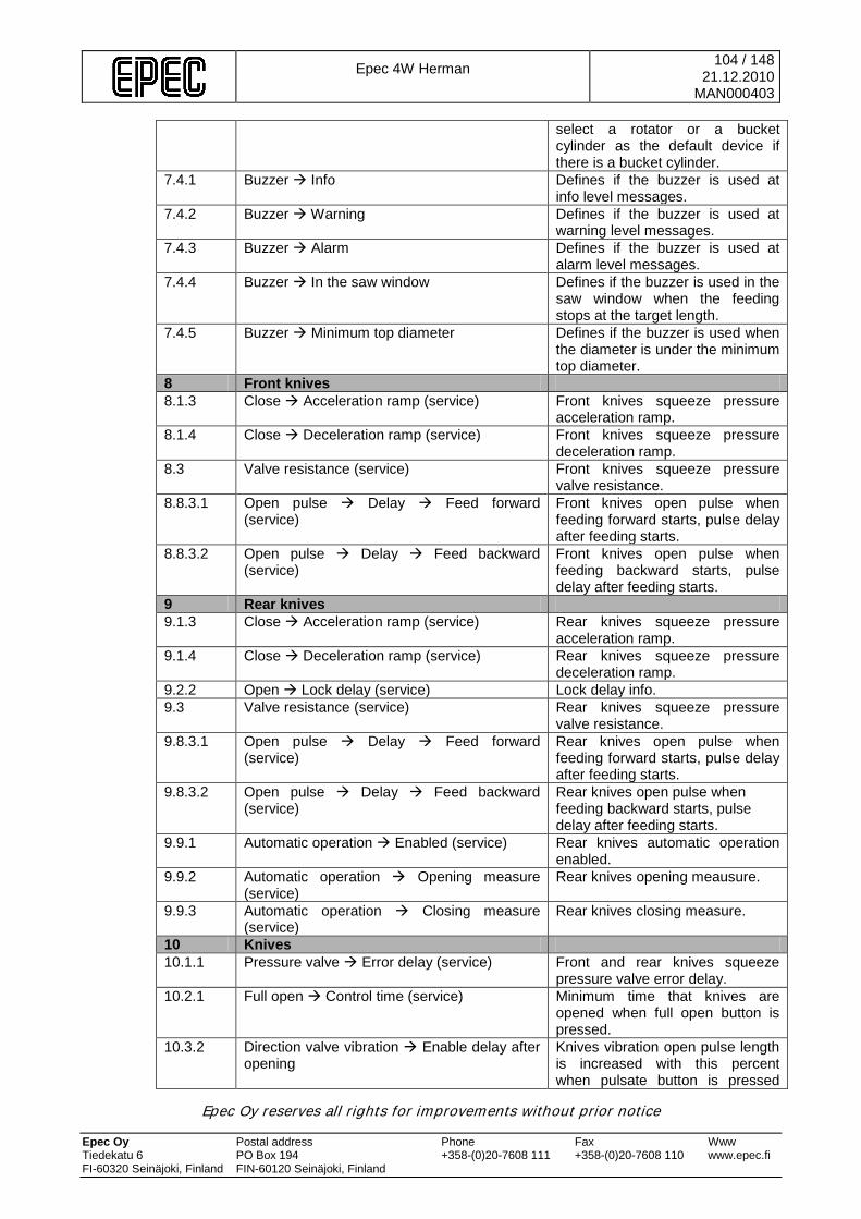
Epec 4W Herman
104 / 148 21.12.2010
MAN000403
Epec Oy reserves all rights for improvements without prior notice Epec Oy Postal address Phone Fax Www Tiedekatu 6 PO Box 194 +358-(0)20-7608 111 +358-(0)20-7608 110 www.epec.fi FI-60320 Seinäjoki, Finland FIN-60120 Seinäjoki, Finland
select a rotator or a bucket cylinder as the default device if there is a bucket cylinder.
7.4.1 Buzzer Info Defines if the buzzer is used at info level messages.
7.4.2 Buzzer Warning Defines if the buzzer is used at warning level messages.
7.4.3 Buzzer Alarm Defines if the buzzer is used at alarm level messages.
7.4.4 Buzzer In the saw window Defines if the buzzer is used in the saw window when the feeding stops at the target length.
7.4.5 Buzzer Minimum top diameter Defines if the buzzer is used when the diameter is under the minimum top diameter.
8 Front knives 8.1.3 Close Acceleration ramp (service) Front knives squeeze pressure
acceleration ramp. 8.1.4 Close Deceleration ramp (service) Front knives squeeze pressure
deceleration ramp. 8.3 Valve resistance (service) Front knives squeeze pressure
valve resistance. 8.8.3.1 Open pulse Delay Feed forward
(service) Front knives open pulse when feeding forward starts, pulse delay after feeding starts.
8.8.3.2 Open pulse Delay Feed backward (service)
Front knives open pulse when feeding backward starts, pulse delay after feeding starts.
9 Rear knives 9.1.3 Close Acceleration ramp (service) Rear knives squeeze pressure
acceleration ramp. 9.1.4 Close Deceleration ramp (service) Rear knives squeeze pressure
deceleration ramp. 9.2.2 Open Lock delay (service) Lock delay info. 9.3 Valve resistance (service) Rear knives squeeze pressure
valve resistance. 9.8.3.1 Open pulse Delay Feed forward
(service) Rear knives open pulse when feeding forward starts, pulse delay after feeding starts.
9.8.3.2 Open pulse Delay Feed backward (service)
Rear knives open pulse when feeding backward starts, pulse delay after feeding starts.
9.9.1 Automatic operation Enabled (service) Rear knives automatic operation enabled.
9.9.2 Automatic operation Opening measure (service)
Rear knives opening meausure.
9.9.3 Automatic operation Closing measure (service)
Rear knives closing measure.
10 Knives 10.1.1 Pressure valve Error delay (service) Front and rear knives squeeze
pressure valve error delay. 10.2.1 Full open Control time (service) Minimum time that knives are
opened when full open button is pressed.
10.3.2 Direction valve vibration Enable delay after opening
Knives vibration open pulse length is increased with this percent when pulsate button is pressed
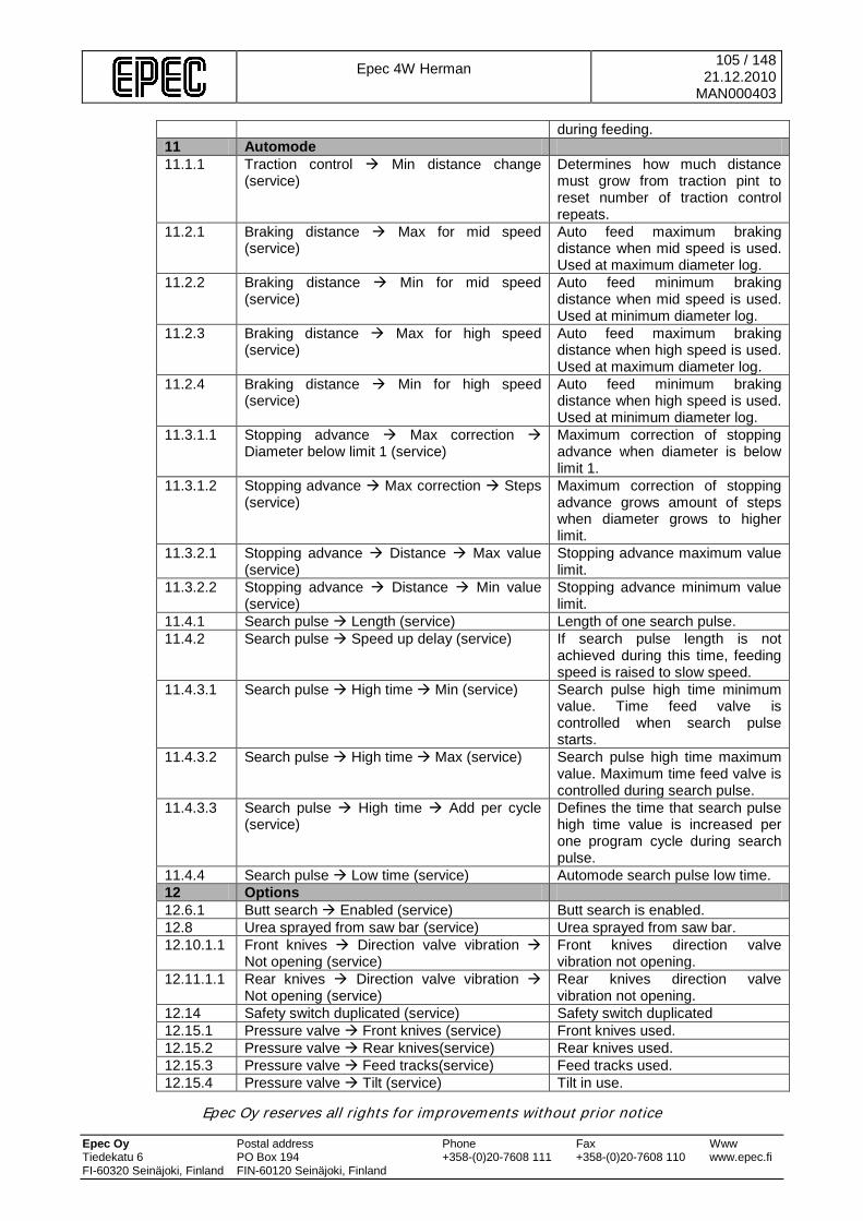
Epec 4W Herman
105 / 148 21.12.2010
MAN000403
Epec Oy reserves all rights for improvements without prior notice Epec Oy Postal address Phone Fax Www Tiedekatu 6 PO Box 194 +358-(0)20-7608 111 +358-(0)20-7608 110 www.epec.fi FI-60320 Seinäjoki, Finland FIN-60120 Seinäjoki, Finland
during feeding. 11 Automode 11.1.1 Traction control Min distance change
(service) Determines how much distance must grow from traction pint to reset number of traction control repeats.
11.2.1 Braking distance Max for mid speed (service)
Auto feed maximum braking distance when mid speed is used. Used at maximum diameter log.
11.2.2 Braking distance Min for mid speed (service)
Auto feed minimum braking distance when mid speed is used. Used at minimum diameter log.
11.2.3 Braking distance Max for high speed (service)
Auto feed maximum braking distance when high speed is used. Used at maximum diameter log.
11.2.4 Braking distance Min for high speed (service)
Auto feed minimum braking distance when high speed is used. Used at minimum diameter log.
11.3.1.1 Stopping advance Max correction Diameter below limit 1 (service)
Maximum correction of stopping advance when diameter is below limit 1.
11.3.1.2 Stopping advance Max correction Steps (service)
Maximum correction of stopping advance grows amount of steps when diameter grows to higher limit.
11.3.2.1 Stopping advance Distance Max value (service)
Stopping advance maximum value limit.
11.3.2.2 Stopping advance Distance Min value (service)
Stopping advance minimum value limit.
11.4.1 Search pulse Length (service) Length of one search pulse. 11.4.2 Search pulse Speed up delay (service) If search pulse length is not
achieved during this time, feeding speed is raised to slow speed.
11.4.3.1 Search pulse High time Min (service) Search pulse high time minimum value. Time feed valve is controlled when search pulse starts.
11.4.3.2 Search pulse High time Max (service) Search pulse high time maximum value. Maximum time feed valve is controlled during search pulse.
11.4.3.3 Search pulse High time Add per cycle (service)
Defines the time that search pulse high time value is increased per one program cycle during search pulse.
11.4.4 Search pulse Low time (service) Automode search pulse low time. 12 Options 12.6.1 Butt search Enabled (service) Butt search is enabled. 12.8 Urea sprayed from saw bar (service) Urea sprayed from saw bar. 12.10.1.1 Front knives Direction valve vibration
Not opening (service) Front knives direction valve vibration not opening.
12.11.1.1 Rear knives Direction valve vibration Not opening (service)
Rear knives direction valve vibration not opening.
12.14 Safety switch duplicated (service) Safety switch duplicated 12.15.1 Pressure valve Front knives (service) Front knives used. 12.15.2 Pressure valve Rear knives(service) Rear knives used. 12.15.3 Pressure valve Feed tracks(service) Feed tracks used. 12.15.4 Pressure valve Tilt (service) Tilt in use.
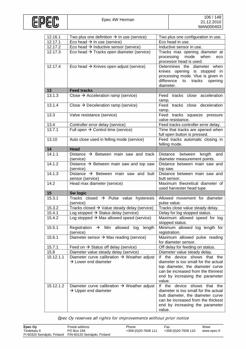
Epec 4W Herman
106 / 148 21.12.2010
MAN000403
Epec Oy reserves all rights for improvements without prior notice Epec Oy Postal address Phone Fax Www Tiedekatu 6 PO Box 194 +358-(0)20-7608 111 +358-(0)20-7608 110 www.epec.fi FI-60320 Seinäjoki, Finland FIN-60120 Seinäjoki, Finland
12.16.1 Two plus one definition In use (service) Two plus one configuration in use. 12.17.1 Eco head In use (service) Eco head in use. 12.17.2 Eco head Inductive sensor (service) Inductive sensor in use. 12.17.3 Eco head Tracks open diameter (service) Tracks max opening diameter at
processing mode when eco processor head is used.
12.17.4 Eco head Knives open adjust (service) Determines the diameter when knives opening is stopped in processing mode. Vlue is given in difference to tracks opening diameter.
13 Feed tracks 13.1.3 Close Acceleration ramp (service) Feed tracks close acceleration
ramp. 13.1.4 Close Deceleration ramp (service) Feed tracks close deceleration
ramp. 13.3 Valve resistance (service) Feed tracks squeeze pressure
valve resistance. 13.4 Controller error delay (service) Feed tracks controller error delay. 13.7.1 Full open Control time (service) Time that tracks are opened when
full open button is pressed. 13.10 Auto close used in felling mode (service) Feed tracks automatic closing in
felling mode. 14 Head 14.1.1 Distance Between main saw and track
(service) Distance between length and diameter measurement points.
14.1.2 Distance Between main saw and top saw (service)
Distance between main saw and top saw.
14.1.3 Distance Between main saw and butt sensor (service)
Distance between main saw and butt sensor.
14.2 Head max diameter (service) Maximum theoretical diameter of used harvester head tupe.
15 Sw logic 15.3.1 Tracks closed Pulse value hysteresis
(service) Allowed movement for diameter pulse value.
15.3.2 Tracks closed Value steady delay (service) Tracks close value steady delay. 15.4.1 Log stopped Status delay (service) Delay for log stopped status. 15.4.2 Log stopped Max allowed speed (service) Maximum allowed speed for log
stopped status. 15.5.1 Registration Min allowed log length
(service) Minimum allowed log length for registration.
15.6.1 Diameter sensor Max reading (service) Maximum allowed pulse reading for diameter sensor.
15.7.1 Feed on Status off delay (service) Off delay for feeding on status. 15.8 Diameter value steady delay (service) Diameter value steady delay. 15.12.1.1 Diameter curve calibration Weather adjust
Lower end diameter If the device shows that the diameter is too small for the actual top diameter, the diameter curve can be increased from the thinnest end by increasing the parameter value.
15.12.1.2 Diameter curve calibration Weather adjust Upper end diameter
If the device shows that the diameter is too small for the actual butt diameter, the diameter curve can be increased from the thickest end by increasing the parameter value.
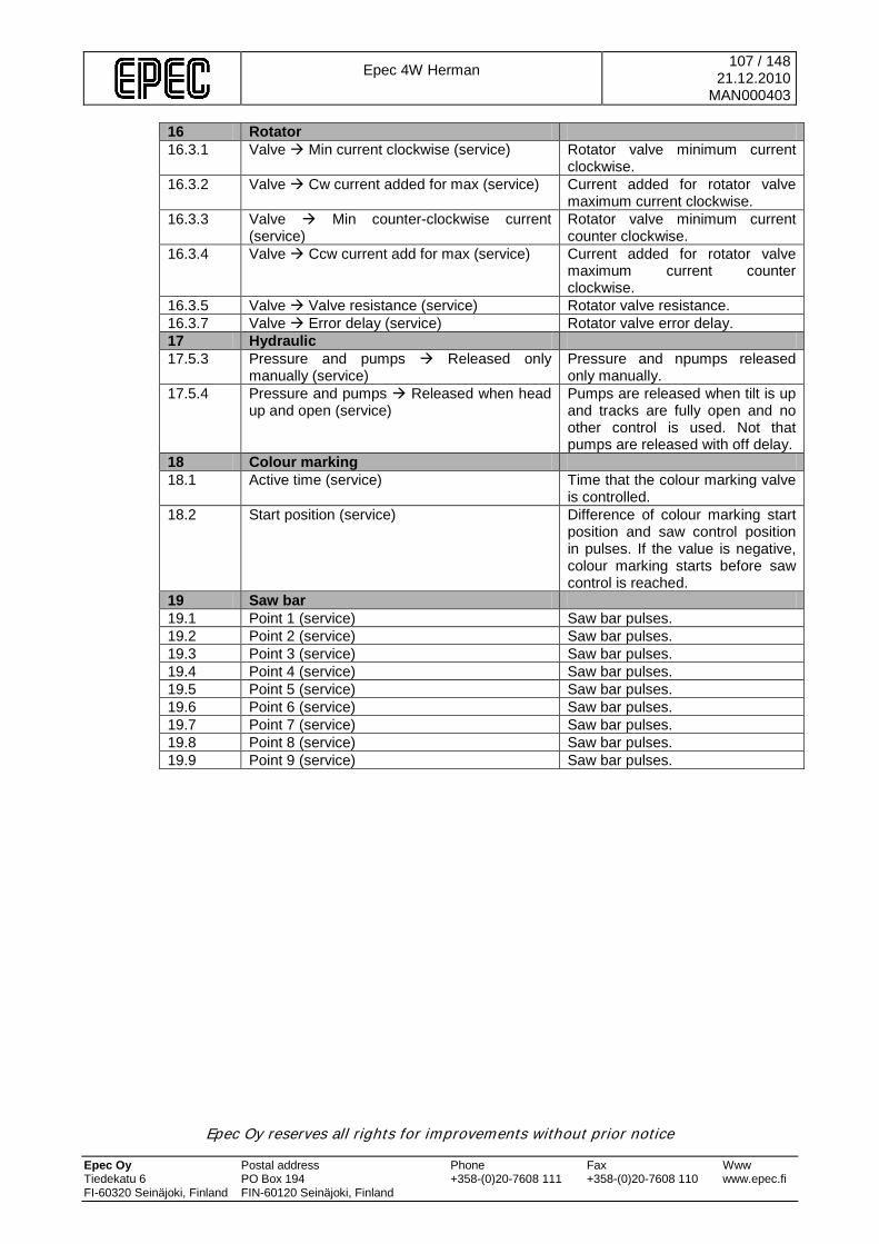
Epec 4W Herman
107 / 148 21.12.2010
MAN000403
Epec Oy reserves all rights for improvements without prior notice Epec Oy Postal address Phone Fax Www Tiedekatu 6 PO Box 194 +358-(0)20-7608 111 +358-(0)20-7608 110 www.epec.fi FI-60320 Seinäjoki, Finland FIN-60120 Seinäjoki, Finland
16 Rotator 16.3.1 Valve Min current clockwise (service) Rotator valve minimum current
clockwise. 16.3.2 Valve Cw current added for max (service) Current added for rotator valve
maximum current clockwise. 16.3.3 Valve Min counter-clockwise current
(service) Rotator valve minimum current counter clockwise.
16.3.4 Valve Ccw current add for max (service) Current added for rotator valve maximum current counter clockwise.
16.3.5 Valve Valve resistance (service) Rotator valve resistance. 16.3.7 Valve Error delay (service) Rotator valve error delay. 17 Hydraulic 17.5.3 Pressure and pumps Released only
manually (service) Pressure and npumps released only manually.
17.5.4 Pressure and pumps Released when head up and open (service)
Pumps are released when tilt is up and tracks are fully open and no other control is used. Not that pumps are released with off delay.
18 Colour marking 18.1 Active time (service) Time that the colour marking valve
is controlled. 18.2 Start position (service) Difference of colour marking start
position and saw control position in pulses. If the value is negative, colour marking starts before saw control is reached.
19 Saw bar 19.1 Point 1 (service) Saw bar pulses. 19.2 Point 2 (service) Saw bar pulses. 19.3 Point 3 (service) Saw bar pulses. 19.4 Point 4 (service) Saw bar pulses. 19.5 Point 5 (service) Saw bar pulses. 19.6 Point 6 (service) Saw bar pulses. 19.7 Point 7 (service) Saw bar pulses. 19.8 Point 8 (service) Saw bar pulses. 19.9 Point 9 (service) Saw bar pulses.
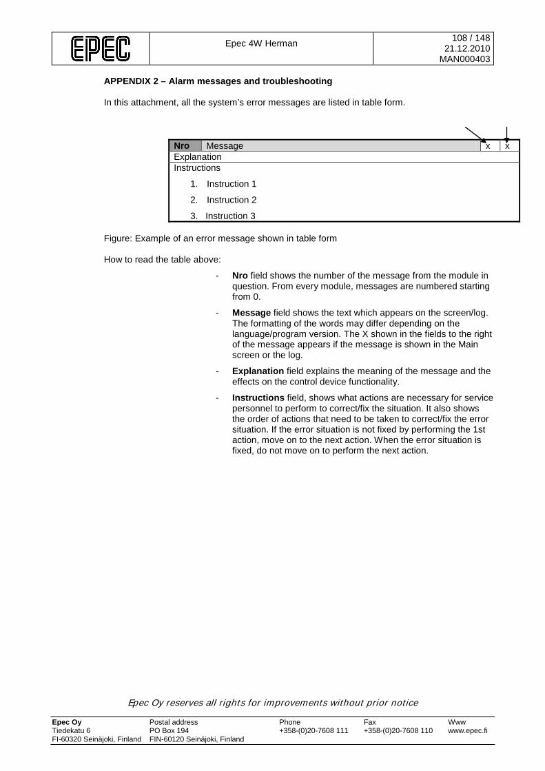
Epec 4W Herman
108 / 148 21.12.2010
MAN000403
Epec Oy reserves all rights for improvements without prior notice Epec Oy Postal address Phone Fax Www Tiedekatu 6 PO Box 194 +358-(0)20-7608 111 +358-(0)20-7608 110 www.epec.fi FI-60320 Seinäjoki, Finland FIN-60120 Seinäjoki, Finland
APPENDIX 2 – Alarm messages and troubleshooting In this attachment, all the system’s error messages are listed in table form.
Nro Message x x Explanation Instructions
1. Instruction 1
2. Instruction 2
3. Instruction 3 Figure: Example of an error message shown in table form How to read the table above:
- Nro field shows the number of the message from the module in question. From every module, messages are numbered starting from 0.
- Message field shows the text which appears on the screen/log. The formatting of the words may differ depending on the language/program version. The X shown in the fields to the right of the message appears if the message is shown in the Main screen or the log.
- Explanation field explains the meaning of the message and the effects on the control device functionality.
- Instructions field, shows what actions are necessary for service personnel to perform to correct/fix the situation. It also shows the order of actions that need to be taken to correct/fix the error situation. If the error situation is not fixed by performing the 1st action, move on to the next action. When the error situation is fixed, do not move on to perform the next action.
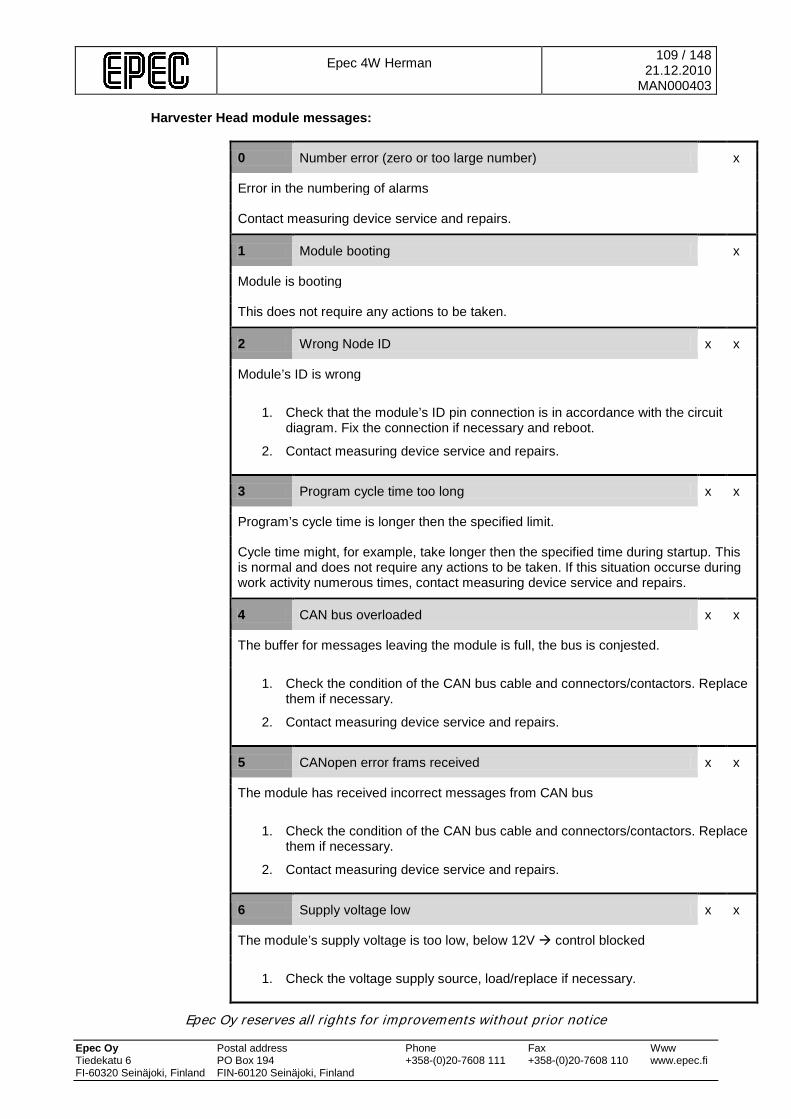
Epec 4W Herman
109 / 148 21.12.2010
MAN000403
Epec Oy reserves all rights for improvements without prior notice Epec Oy Postal address Phone Fax Www Tiedekatu 6 PO Box 194 +358-(0)20-7608 111 +358-(0)20-7608 110 www.epec.fi FI-60320 Seinäjoki, Finland FIN-60120 Seinäjoki, Finland
Harvester Head module messages:
0 Number error (zero or too large number) x
Error in the numbering of alarms
Contact measuring device service and repairs.
1 Module booting x
Module is booting
This does not require any actions to be taken.
2 Wrong Node ID x x
Module’s ID is wrong
1. Check that the module’s ID pin connection is in accordance with the circuit diagram. Fix the connection if necessary and reboot.
2. Contact measuring device service and repairs.
3 Program cycle time too long x x
Program’s cycle time is longer then the specified limit.
Cycle time might, for example, take longer then the specified time during startup. This is normal and does not require any actions to be taken. If this situation occurse during work activity numerous times, contact measuring device service and repairs.
4 CAN bus overloaded x x
The buffer for messages leaving the module is full, the bus is conjested.
1. Check the condition of the CAN bus cable and connectors/contactors. Replace them if necessary.
2. Contact measuring device service and repairs.
5 CANopen error frams received x x
The module has received incorrect messages from CAN bus
1. Check the condition of the CAN bus cable and connectors/contactors. Replace them if necessary.
2. Contact measuring device service and repairs.
6 Supply voltage low x x
The module’s supply voltage is too low, below 12V control blocked
1. Check the voltage supply source, load/replace if necessary.
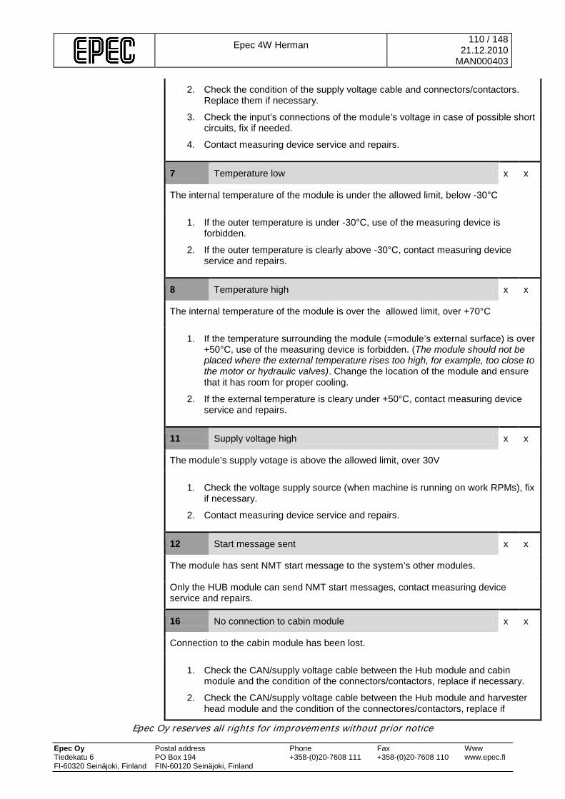
Epec 4W Herman
110 / 148 21.12.2010
MAN000403
Epec Oy reserves all rights for improvements without prior notice Epec Oy Postal address Phone Fax Www Tiedekatu 6 PO Box 194 +358-(0)20-7608 111 +358-(0)20-7608 110 www.epec.fi FI-60320 Seinäjoki, Finland FIN-60120 Seinäjoki, Finland
2. Check the condition of the supply voltage cable and connectors/contactors. Replace them if necessary.
3. Check the input’s connections of the module’s voltage in case of possible short circuits, fix if needed.
4. Contact measuring device service and repairs.
7 Temperature low x x
The internal temperature of the module is under the allowed limit, below -30°C
1. If the outer temperature is under -30°C, use of the measuring device is forbidden.
2. If the outer temperature is clearly above -30°C, contact measuring device service and repairs.
8 Temperature high x x
The internal temperature of the module is over the allowed limit, over +70°C
1. If the temperature surrounding the module (=module’s external surface) is over +50°C, use of the measuring device is forbidden. (The module should not be placed where the external temperature rises too high, for example, too close to the motor or hydraulic valves). Change the location of the module and ensure that it has room for proper cooling.
2. If the external temperature is cleary under +50°C, contact measuring device service and repairs.
11 Supply voltage high x x
The module’s supply votage is above the allowed limit, over 30V
1. Check the voltage supply source (when machine is running on work RPMs), fix if necessary.
2. Contact measuring device service and repairs.
12 Start message sent x x
The module has sent NMT start message to the system’s other modules.
Only the HUB module can send NMT start messages, contact measuring device service and repairs.
16 No connection to cabin module x x
Connection to the cabin module has been lost.
1. Check the CAN/supply voltage cable between the Hub module and cabin module and the condition of the connectors/contactors, replace if necessary.
2. Check the CAN/supply voltage cable between the Hub module and harvester head module and the condition of the connectores/contactors, replace if
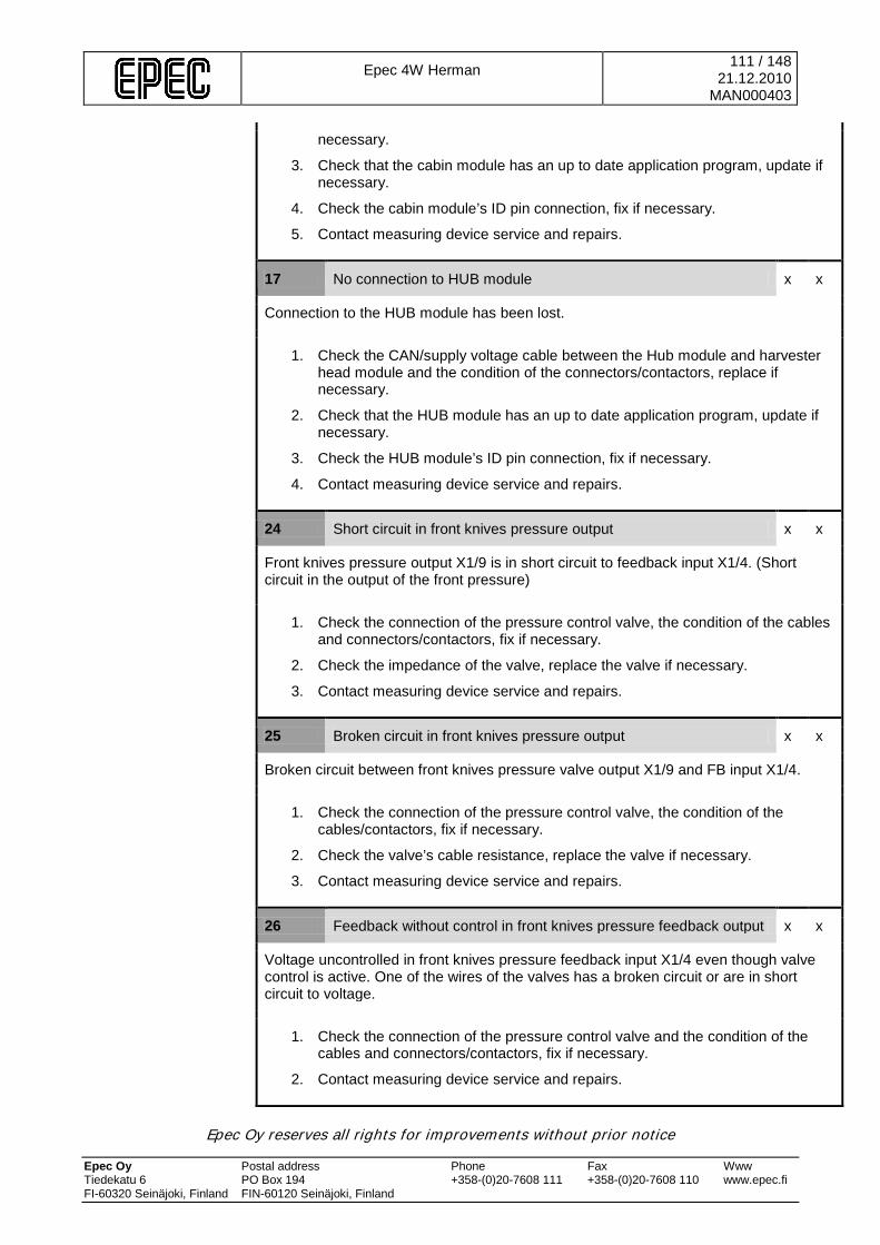
Epec 4W Herman
111 / 148 21.12.2010
MAN000403
Epec Oy reserves all rights for improvements without prior notice Epec Oy Postal address Phone Fax Www Tiedekatu 6 PO Box 194 +358-(0)20-7608 111 +358-(0)20-7608 110 www.epec.fi FI-60320 Seinäjoki, Finland FIN-60120 Seinäjoki, Finland
necessary.
3. Check that the cabin module has an up to date application program, update if necessary.
4. Check the cabin module’s ID pin connection, fix if necessary.
5. Contact measuring device service and repairs.
17 No connection to HUB module x x
Connection to the HUB module has been lost.
1. Check the CAN/supply voltage cable between the Hub module and harvester head module and the condition of the connectors/contactors, replace if necessary.
2. Check that the HUB module has an up to date application program, update if necessary.
3. Check the HUB module’s ID pin connection, fix if necessary.
4. Contact measuring device service and repairs.
24 Short circuit in front knives pressure output x x
Front knives pressure output X1/9 is in short circuit to feedback input X1/4. (Short circuit in the output of the front pressure)
1. Check the connection of the pressure control valve, the condition of the cables and connectors/contactors, fix if necessary.
2. Check the impedance of the valve, replace the valve if necessary.
3. Contact measuring device service and repairs.
25 Broken circuit in front knives pressure output x x
Broken circuit between front knives pressure valve output X1/9 and FB input X1/4.
1. Check the connection of the pressure control valve, the condition of the cables/contactors, fix if necessary.
2. Check the valve’s cable resistance, replace the valve if necessary.
3. Contact measuring device service and repairs.
26 Feedback without control in front knives pressure feedback output x x
Voltage uncontrolled in front knives pressure feedback input X1/4 even though valve control is active. One of the wires of the valves has a broken circuit or are in short circuit to voltage.
1. Check the connection of the pressure control valve and the condition of the cables and connectors/contactors, fix if necessary.
2. Contact measuring device service and repairs.
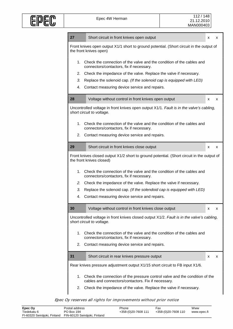
Epec 4W Herman
112 / 148 21.12.2010
MAN000403
Epec Oy reserves all rights for improvements without prior notice Epec Oy Postal address Phone Fax Www Tiedekatu 6 PO Box 194 +358-(0)20-7608 111 +358-(0)20-7608 110 www.epec.fi FI-60320 Seinäjoki, Finland FIN-60120 Seinäjoki, Finland
27 Short circuit in front knives open output x x
Front knives open output X1/1 short to ground potential. (Short circuit in the output of the front knives open)
1. Check the connection of the valve and the condition of the cables and connectors/contactors, fix if necessary.
2. Check the impedance of the valve. Replace the valve if necessary.
3. Replace the solenoid cap. (If the solenoid cap is equipped with LED)
4. Contact measuring device service and repairs.
28 Voltage without control in front knives open output x x
Uncontrolled voltage in front knives open output X1/1. Fault is in the valve’s cabling, short circuit to voltage.
1. Check the connection of the valve and the condition of the cables and connectors/contactors, fix if necessary.
2. Contact measuring device service and repairs.
29 Short circuit in front knives close output x x
Front knives closed output X1/2 short to ground potential. (Short circuit in the output of the front knives closed)
1. Check the connection of the valve and the condition of the cables and connectors/contactors, fix if necessary.
2. Check the impedance of the valve. Replace the valve if necessary.
3. Replace the solenoid cap. (If the solendoid cap is equipped with LED)
4. Contact measuring device service and repairs.
30 Voltage without control in front knives close output x x
Uncontrolled voltage in front knives closed output X1/2. Fault is in the valve’s cabling, short circuit to voltage.
1. Check the connection of the valve and the condition of the cables and connectors/contactors, fix if necessary.
2. Contact measuring device service and repairs.
31 Short circuit in rear knives pressure output x x
Rear knives pressure adjustment output X1/15 short circuit to FB input X1/6.
1. Check the connection of the pressure control valve and the condition of the cables and connectors/contactors. Fix if necessary.
2. Check the impedance of the valve. Replace the valve if necessary.
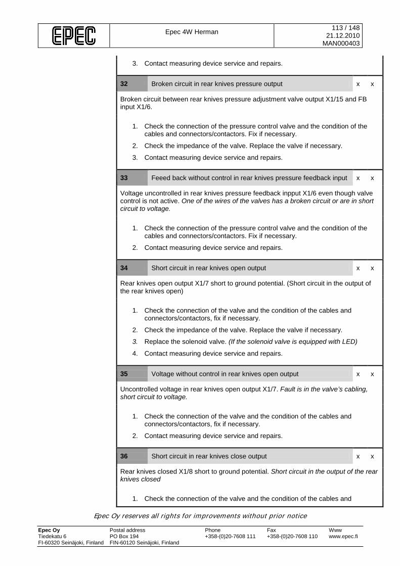
Epec 4W Herman
113 / 148 21.12.2010
MAN000403
Epec Oy reserves all rights for improvements without prior notice Epec Oy Postal address Phone Fax Www Tiedekatu 6 PO Box 194 +358-(0)20-7608 111 +358-(0)20-7608 110 www.epec.fi FI-60320 Seinäjoki, Finland FIN-60120 Seinäjoki, Finland
3. Contact measuring device service and repairs.
32 Broken circuit in rear knives pressure output x x
Broken circuit between rear knives pressure adjustment valve output X1/15 and FB input X1/6.
1. Check the connection of the pressure control valve and the condition of the cables and connectors/contactors. Fix if necessary.
2. Check the impedance of the valve. Replace the valve if necessary.
3. Contact measuring device service and repairs.
33 Feeed back without control in rear knives pressure feedback input x x
Voltage uncontrolled in rear knives pressure feedback inpput X1/6 even though valve control is not active. One of the wires of the valves has a broken circuit or are in short circuit to voltage.
1. Check the connection of the pressure control valve and the condition of the cables and connectors/contactors. Fix if necessary.
2. Contact measuring device service and repairs.
34 Short circuit in rear knives open output x x
Rear knives open output X1/7 short to ground potential. (Short circuit in the output of the rear knives open)
1. Check the connection of the valve and the condition of the cables and connectors/contactors, fix if necessary.
2. Check the impedance of the valve. Replace the valve if necessary.
3. Replace the solenoid valve. (If the solenoid valve is equipped with LED)
4. Contact measuring device service and repairs.
35 Voltage without control in rear knives open output x x
Uncontrolled voltage in rear knives open output X1/7. Fault is in the valve’s cabling, short circuit to voltage.
1. Check the connection of the valve and the condition of the cables and connectors/contactors, fix if necessary.
2. Contact measuring device service and repairs.
36 Short circuit in rear knives close output x x
Rear knives closed X1/8 short to ground potential. Short circuit in the output of the rear knives closed
1. Check the connection of the valve and the condition of the cables and
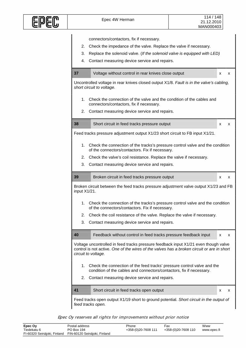
Epec 4W Herman
114 / 148 21.12.2010
MAN000403
Epec Oy reserves all rights for improvements without prior notice Epec Oy Postal address Phone Fax Www Tiedekatu 6 PO Box 194 +358-(0)20-7608 111 +358-(0)20-7608 110 www.epec.fi FI-60320 Seinäjoki, Finland FIN-60120 Seinäjoki, Finland
connectors/contactors, fix if necessary.
2. Check the impedance of the valve. Replace the valve if necessary.
3. Replace the solenoid valve. (If the solenoid valve is equipped with LED)
4. Contact measuring device service and repairs.
37 Voltage without control in rear knives close output x x
Uncontrolled voltage in rear knives closed output X1/8. Fault is in the valve’s cabling, short circuit to voltage.
1. Check the connection of the valve and the condition of the cables and connectors/contactors, fix if necessary.
2. Contact measuring device service and repairs.
38 Short circuit in feed tracks pressure output x x
Feed tracks pressure adjustment output X1/23 short circuit to FB input X1/21.
1. Check the connection of the tracks’s pressure control valve and the condition of the connectors/contactors. Fix if necessary.
2. Check the valve’s coil resistance. Replace the valve if necessary.
3. Contact measuring device service and repairs.
39 Broken circuit in feed tracks pressure output x x
Broken circuit between the feed tracks pressure adjustment valve output X1/23 and FB input X1/21.
1. Check the connection of the tracks’s pressure control valve and the condition of the connectors/contactors. Fix if necessary.
2. Check the coil resistance of the valve. Replace the valve if necessary.
3. Contact measuring device service and repairs.
40 Feedback without control in feed tracks pressure feedback input x x
Voltage uncontrolled in feed tracks pressure feedback input X1/21 even though valve control is not active. One of the wires of the valves has a broken circuit or are in short circuit to voltage.
1. Check the connection of the feed tracks’ pressure control valve and the condition of the cables and connectors/contactors, fix if necessary.
2. Contact measuring device service and repairs.
41 Short circuit in feed tracks open output x x
Feed tracks open output X1/19 short to ground potential. Short circuit in the output of feed tracks open.

Epec 4W Herman
115 / 148 21.12.2010
MAN000403
Epec Oy reserves all rights for improvements without prior notice Epec Oy Postal address Phone Fax Www Tiedekatu 6 PO Box 194 +358-(0)20-7608 111 +358-(0)20-7608 110 www.epec.fi FI-60320 Seinäjoki, Finland FIN-60120 Seinäjoki, Finland
1. Check the connection of the valve and the condition of the cables and connectors/contactors, fix if necessary.
2. Check the impedance of the valve. Replace the valve if necessary.
3. Replace the solenoid valve. (If the solenoid valve is equipped with LED)
4. Contact measuring device service and repairs.
42 Voltage without control in feed tracks open output x x
Uncontrolled voltage in feed tracks open output X1/19. Fault is in the valve’s cabling, short circuit to voltage.
1. Check the connection of the valve and the condition of the cables and connectors/contactors, fix if necessary.
2. Contact measuring device service and repairs.
43 Short circuit in feed tracks close output x x
Feed tracks close output X1/18 short to ground potential. Short circuit in the output of feed tracks close.
1. Check the connection of the valve and the condition of the cables and connectors/contactors, fix if necessary.
2. Check the impedance of the valve. Replace the valve if necessary.
3. Replace the solenoid valve. (If the solenoid valve is equipped with LED)
4. Contact measuring device service and repairs.
44 Voltage without control in feed tracks close output x x
Uncontrolled voltage in feed tracks close output X1/18. Fault is in the valve’s cabling, short circuit to voltage.
1. Check the connection of the valve and the condition of the cables and connectors/contactors, fix if necessary.
2. Contact measuring device service and repairs.
45 Short circuit in feed forward slow output x x
Feed forward slow output X1/11 short to ground potential. Short circuit in the output of feed forward slow.
1. Check the connection of the valve and the condition of the cables and connectors/contactors, fix if necessary.l
2. Check the impedance of the valve. Replace the valve if necessary.
3. Replace the solenoid valve. (If the solenoid valve is equipped with LED)
4. Contact measuring device service and repairs.
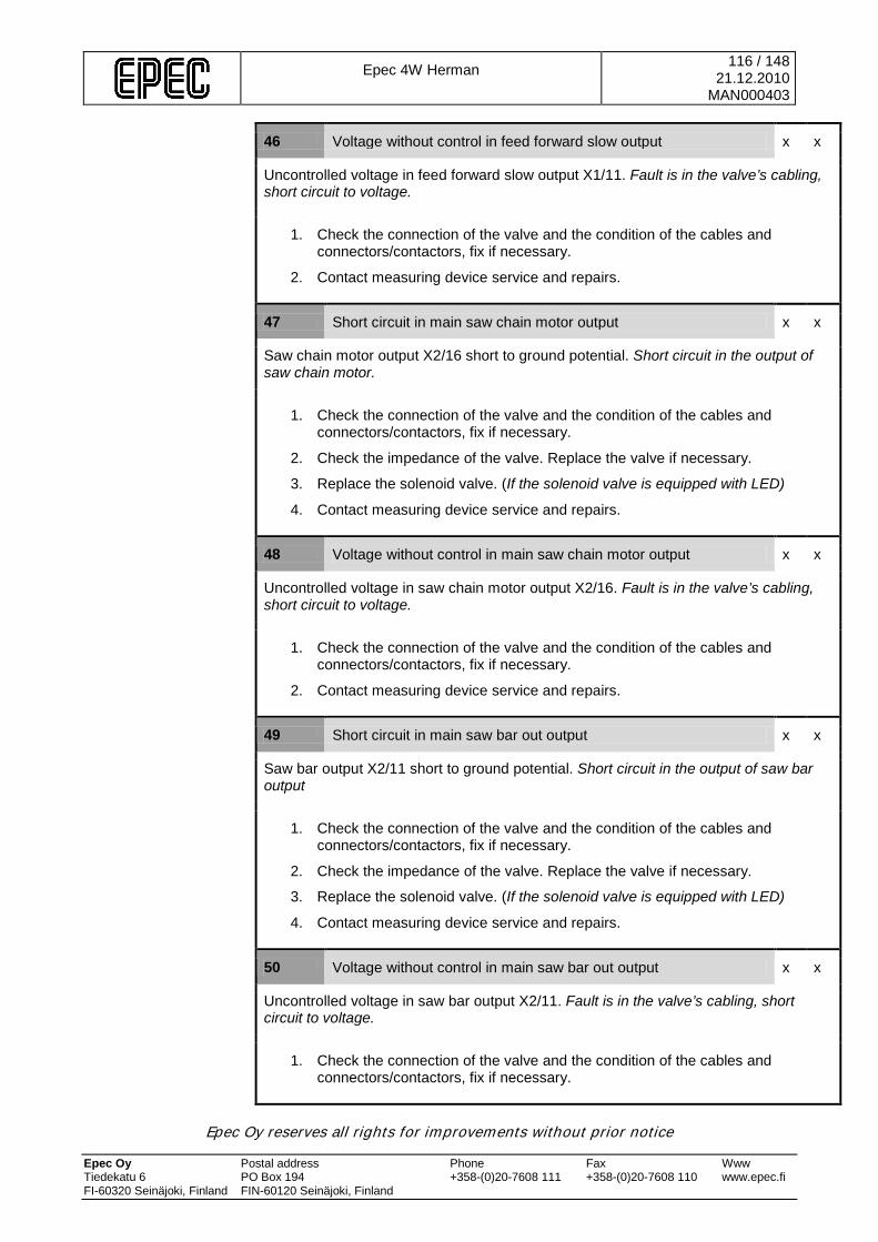
Epec 4W Herman
116 / 148 21.12.2010
MAN000403
Epec Oy reserves all rights for improvements without prior notice Epec Oy Postal address Phone Fax Www Tiedekatu 6 PO Box 194 +358-(0)20-7608 111 +358-(0)20-7608 110 www.epec.fi FI-60320 Seinäjoki, Finland FIN-60120 Seinäjoki, Finland
46 Voltage without control in feed forward slow output x x
Uncontrolled voltage in feed forward slow output X1/11. Fault is in the valve’s cabling, short circuit to voltage.
1. Check the connection of the valve and the condition of the cables and connectors/contactors, fix if necessary.
2. Contact measuring device service and repairs.
47 Short circuit in main saw chain motor output x x
Saw chain motor output X2/16 short to ground potential. Short circuit in the output of saw chain motor.
1. Check the connection of the valve and the condition of the cables and connectors/contactors, fix if necessary.
2. Check the impedance of the valve. Replace the valve if necessary.
3. Replace the solenoid valve. (If the solenoid valve is equipped with LED)
4. Contact measuring device service and repairs.
48 Voltage without control in main saw chain motor output x x
Uncontrolled voltage in saw chain motor output X2/16. Fault is in the valve’s cabling, short circuit to voltage.
1. Check the connection of the valve and the condition of the cables and connectors/contactors, fix if necessary.
2. Contact measuring device service and repairs.
49 Short circuit in main saw bar out output x x
Saw bar output X2/11 short to ground potential. Short circuit in the output of saw bar output
1. Check the connection of the valve and the condition of the cables and connectors/contactors, fix if necessary.
2. Check the impedance of the valve. Replace the valve if necessary.
3. Replace the solenoid valve. (If the solenoid valve is equipped with LED)
4. Contact measuring device service and repairs.
50 Voltage without control in main saw bar out output x x
Uncontrolled voltage in saw bar output X2/11. Fault is in the valve’s cabling, short circuit to voltage.
1. Check the connection of the valve and the condition of the cables and connectors/contactors, fix if necessary.
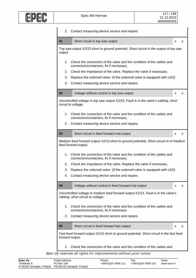
Epec 4W Herman
117 / 148 21.12.2010
MAN000403
Epec Oy reserves all rights for improvements without prior notice Epec Oy Postal address Phone Fax Www Tiedekatu 6 PO Box 194 +358-(0)20-7608 111 +358-(0)20-7608 110 www.epec.fi FI-60320 Seinäjoki, Finland FIN-60120 Seinäjoki, Finland
2. Contact measuring device service and repairs.
51 Short circuit in top saw output x x
Top saw output X2/23 short to ground potential. Short circuit in the output of top saw output
1. Check the connection of the valve and the condition of the cables and connectors/contactors, fix if necessary.
2. Check the impedance of the valve. Replace the valve if necessary.
3. Replace the solenoid valve. (If the solenoid valve is equipped with LED)
4. Contact measuring device service and repairs.
52 Voltage without control in top saw output x x
Uncontrolled voltage in top saw output X2/23. Fault is in the valve’s cabling, short circuit to voltage.
1. Check the connection of the valve and the condition of the cables and connectors/contactors, fix if necessary.
2. Contact measuring device service and repairs.
53 Short circuit in feed forward mid output x x
Medium feed forward output X2/13 short to ground potential. Short circuit in of medium feed forward output.
1. Check the connection of the valve and the condition of the cables and connectors/contactors, fix if necessary.
2. Check the impedance of the valve. Replace the valve if necessary.
3. Replace the solenoid valve. (If the solenoid valve is equipped with LED)
4. Contact measuring device service and repairs.
54 Voltage without control in feed forward mid output x x
Uncontrolled voltage in medium feed forward output X2/13. Fault is in the valve’s cabling, short circuit to voltage.
1. Check the connection of the valve and the condition of the cables and connectors/contactors, fix if necessary.
2. Contact measuring device service and repairs.
55 Short circuit in feed forward fast output x x
Fast feed forward output X2/15 short to ground potential. Short circuit in the fast feed forward output.
1. Check the connection of the valve and the condition of the cables and

Epec 4W Herman
118 / 148 21.12.2010
MAN000403
Epec Oy reserves all rights for improvements without prior notice Epec Oy Postal address Phone Fax Www Tiedekatu 6 PO Box 194 +358-(0)20-7608 111 +358-(0)20-7608 110 www.epec.fi FI-60320 Seinäjoki, Finland FIN-60120 Seinäjoki, Finland
connectors/contactors, fix if necessary.
2. Check the impedance of the valve. Replace the valve if necessary.
3. Replace the solenoid valve. (If the solenoid valve is equipped with LED)
4. Contact measuring device service and repairs.
56 Voltage without control in feed forward fast output x x
Uncontrolled voltage in fast feed forward output X2/15. Fault is in the valve’s cabling, short circuit to voltage.
1. Check the connection of the valve and the condition of the cables and connectors/contactors, fix if necessary.
2. Contact measuring device service and repairs.
57 Short circuit in tilt up output x x
Tilt up output X2/7 short to ground potential. Short circuit in tilt up output.
1. Check the connection of the valve and the condition of the cables and connectors/contactors, fix if necessary.
2. Check the impedance of the valve. Replace the valve if necessary.
3. Replace the solenoid valve. (If the solenoid valve is equipped with LED)
4. Contact measuring device service and repairs.
58 Voltage without control in tilt up output x x
Uncontrolled voltage in tilt up output X2/7. Fault is in the valve’s cabling, short circuit to voltage.
1. Check the connection of the valve and the condition of the cables and connectors/contactors, fix if necessary.
2. Contact measuring device service and repairs.
59 Short circuit in tilt down output x x
Tilt down output X2/8 short to ground potential. Short circuit in tilt down output.
1. Check the connection of the valve and the condition of the cables and connectors/contactors, fix if necessary.
2. Check the impedance of the valve. Replace the valve if necessary.
3. Replace the solenoid valve. (If the solenoid valve is equipped with LED)
4. Contact measuring device service and repairs.
60 Voltage without control in tilt down output x x
Uncontrolled voltage in tilt up output X2/8. Fault is in the valve’s cabling, short circuit to voltage.
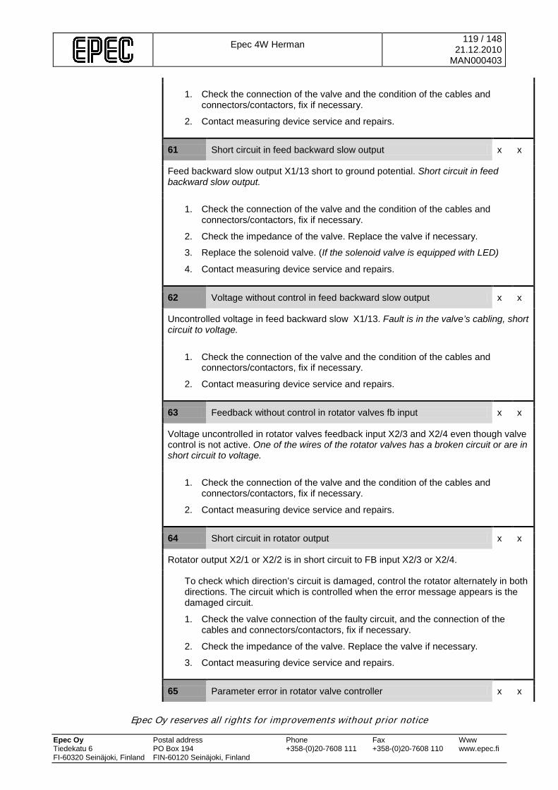
Epec 4W Herman
119 / 148 21.12.2010
MAN000403
Epec Oy reserves all rights for improvements without prior notice Epec Oy Postal address Phone Fax Www Tiedekatu 6 PO Box 194 +358-(0)20-7608 111 +358-(0)20-7608 110 www.epec.fi FI-60320 Seinäjoki, Finland FIN-60120 Seinäjoki, Finland
1. Check the connection of the valve and the condition of the cables and connectors/contactors, fix if necessary.
2. Contact measuring device service and repairs.
61 Short circuit in feed backward slow output x x
Feed backward slow output X1/13 short to ground potential. Short circuit in feed backward slow output.
1. Check the connection of the valve and the condition of the cables and connectors/contactors, fix if necessary.
2. Check the impedance of the valve. Replace the valve if necessary.
3. Replace the solenoid valve. (If the solenoid valve is equipped with LED)
4. Contact measuring device service and repairs.
62 Voltage without control in feed backward slow output x x
Uncontrolled voltage in feed backward slow X1/13. Fault is in the valve’s cabling, short circuit to voltage.
1. Check the connection of the valve and the condition of the cables and connectors/contactors, fix if necessary.
2. Contact measuring device service and repairs.
63 Feedback without control in rotator valves fb input x x
Voltage uncontrolled in rotator valves feedback input X2/3 and X2/4 even though valve control is not active. One of the wires of the rotator valves has a broken circuit or are in short circuit to voltage.
1. Check the connection of the valve and the condition of the cables and connectors/contactors, fix if necessary.
2. Contact measuring device service and repairs.
64 Short circuit in rotator output x x
Rotator output X2/1 or X2/2 is in short circuit to FB input X2/3 or X2/4.
To check which direction’s circuit is damaged, control the rotator alternately in both directions. The circuit which is controlled when the error message appears is the damaged circuit.
1. Check the valve connection of the faulty circuit, and the connection of the cables and connectors/contactors, fix if necessary.
2. Check the impedance of the valve. Replace the valve if necessary.
3. Contact measuring device service and repairs.
65 Parameter error in rotator valve controller x x

Epec 4W Herman
120 / 148 21.12.2010
MAN000403
Epec Oy reserves all rights for improvements without prior notice Epec Oy Postal address Phone Fax Www Tiedekatu 6 PO Box 194 +358-(0)20-7608 111 +358-(0)20-7608 110 www.epec.fi FI-60320 Seinäjoki, Finland FIN-60120 Seinäjoki, Finland
There is a parameter conflict in the rotator’s current regulator or the parameter value is not within the allowed limits.
1. Check the valve calibration. Calibrate again if necessary.
2. Check the rotator ramp parameter values from the measuring device settings. Fix if necessary.
3. Contact measuring device service and repairs.
66 Parameter error in front knives squeeze pressure valve controller x x
There is a parameter conflict in the front knives pressure controller’s current regulator or the parameter value is not within the allowed limits.
1. Check the current settings and the pressure curve of the pressure controller. Adjust if necessary.
2. Check the front knives pressure control ramp parameter values from the measuring device settings. Fix if necessary.
3. Contact measuring device service and repairs.
67 Parameter error in rear knives squeeze pressure valve controller x x
There is a parameter conflict in the rear knives pressure controller’s current regulator or the parameter value is not within the allowed limits.
1. Check the current settings and the pressure curve of the pressure controller. Adjust if necessary.
2. Check the rear knives pressure control ramp parameter values from the measuring device settings. Fix if necessary.
3. Contact measuring device service and repairs.
68 Parameter error in feed tracks squeeze pressure valve controller x x
There is a parameter conflict in the feed tracks pressure controller’s current regulator or the parameter value is not within the allowed limits.
1. Check the current settings and the pressure curve of the pressure controller. Adjust if necessary.
2. Check the feed tracks pressure control ramp parameter values from the measuring device settings. Fix if necessary.
3. Contact measuring device service and repairs.
69 Short circuit in colour marking 1 output x x
Colour marking output X2/23 short to ground potential. Short circuit in colour marking output.
1. Check the connection of the valve and the condition of the cables and connectors/contactors, fix if necessary.
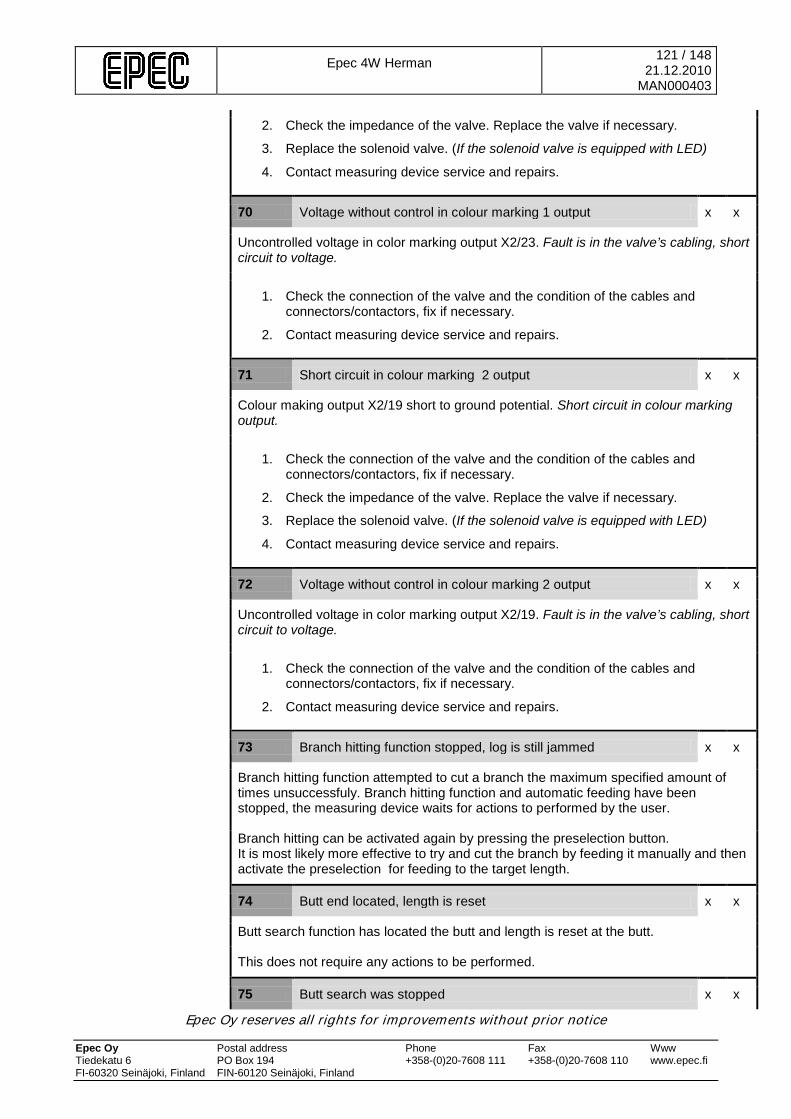
Epec 4W Herman
121 / 148 21.12.2010
MAN000403
Epec Oy reserves all rights for improvements without prior notice Epec Oy Postal address Phone Fax Www Tiedekatu 6 PO Box 194 +358-(0)20-7608 111 +358-(0)20-7608 110 www.epec.fi FI-60320 Seinäjoki, Finland FIN-60120 Seinäjoki, Finland
2. Check the impedance of the valve. Replace the valve if necessary.
3. Replace the solenoid valve. (If the solenoid valve is equipped with LED)
4. Contact measuring device service and repairs.
70 Voltage without control in colour marking 1 output x x
Uncontrolled voltage in color marking output X2/23. Fault is in the valve’s cabling, short circuit to voltage.
1. Check the connection of the valve and the condition of the cables and connectors/contactors, fix if necessary.
2. Contact measuring device service and repairs.
71 Short circuit in colour marking 2 output x x
Colour making output X2/19 short to ground potential. Short circuit in colour marking output.
1. Check the connection of the valve and the condition of the cables and connectors/contactors, fix if necessary.
2. Check the impedance of the valve. Replace the valve if necessary.
3. Replace the solenoid valve. (If the solenoid valve is equipped with LED)
4. Contact measuring device service and repairs.
72 Voltage without control in colour marking 2 output x x
Uncontrolled voltage in color marking output X2/19. Fault is in the valve’s cabling, short circuit to voltage.
1. Check the connection of the valve and the condition of the cables and connectors/contactors, fix if necessary.
2. Contact measuring device service and repairs.
73 Branch hitting function stopped, log is still jammed x x
Branch hitting function attempted to cut a branch the maximum specified amount of times unsuccessfuly. Branch hitting function and automatic feeding have been stopped, the measuring device waits for actions to performed by the user.
Branch hitting can be activated again by pressing the preselection button. It is most likely more effective to try and cut the branch by feeding it manually and then activate the preselection for feeding to the target length.
74 Butt end located, length is reset x x
Butt search function has located the butt and length is reset at the butt.
This does not require any actions to be performed.
75 Butt search was stopped x x
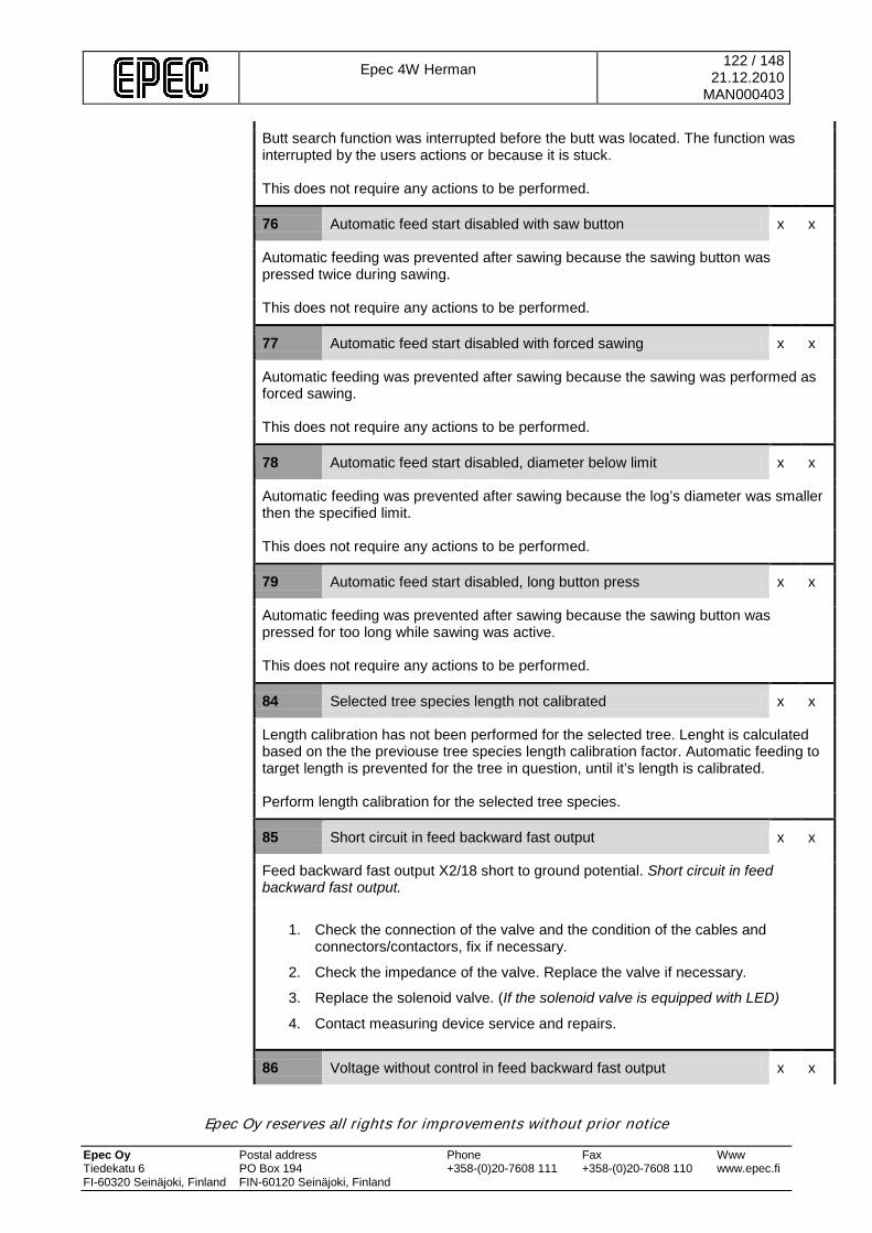
Epec 4W Herman
122 / 148 21.12.2010
MAN000403
Epec Oy reserves all rights for improvements without prior notice Epec Oy Postal address Phone Fax Www Tiedekatu 6 PO Box 194 +358-(0)20-7608 111 +358-(0)20-7608 110 www.epec.fi FI-60320 Seinäjoki, Finland FIN-60120 Seinäjoki, Finland
Butt search function was interrupted before the butt was located. The function was interrupted by the users actions or because it is stuck.
This does not require any actions to be performed.
76 Automatic feed start disabled with saw button x x
Automatic feeding was prevented after sawing because the sawing button was pressed twice during sawing.
This does not require any actions to be performed.
77 Automatic feed start disabled with forced sawing x x
Automatic feeding was prevented after sawing because the sawing was performed as forced sawing.
This does not require any actions to be performed.
78 Automatic feed start disabled, diameter below limit x x
Automatic feeding was prevented after sawing because the log’s diameter was smaller then the specified limit.
This does not require any actions to be performed.
79 Automatic feed start disabled, long button press x x
Automatic feeding was prevented after sawing because the sawing button was pressed for too long while sawing was active.
This does not require any actions to be performed.
84 Selected tree species length not calibrated x x
Length calibration has not been performed for the selected tree. Lenght is calculated based on the the previouse tree species length calibration factor. Automatic feeding to target length is prevented for the tree in question, until it’s length is calibrated.
Perform length calibration for the selected tree species.
85 Short circuit in feed backward fast output x x
Feed backward fast output X2/18 short to ground potential. Short circuit in feed backward fast output.
1. Check the connection of the valve and the condition of the cables and connectors/contactors, fix if necessary.
2. Check the impedance of the valve. Replace the valve if necessary.
3. Replace the solenoid valve. (If the solenoid valve is equipped with LED)
4. Contact measuring device service and repairs.
86 Voltage without control in feed backward fast output x x
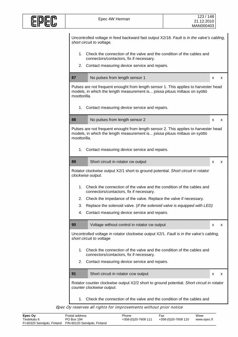
Epec 4W Herman
123 / 148 21.12.2010
MAN000403
Epec Oy reserves all rights for improvements without prior notice Epec Oy Postal address Phone Fax Www Tiedekatu 6 PO Box 194 +358-(0)20-7608 111 +358-(0)20-7608 110 www.epec.fi FI-60320 Seinäjoki, Finland FIN-60120 Seinäjoki, Finland
Uncontrolled voltage in feed backward fast output X2/18. Fault is in the valve’s cabling, short circuit to voltage.
1. Check the connection of the valve and the condition of the cables and connectors/contactors, fix if necessary.
2. Contact measuring device service and repairs.
87 No pulses from length sensor 1 x x
Pulses are not frequent enought from length sensor 1. This applies to harvester head models, in which the length measurement is... joissa pituus mittaus on syöttö moottorilla.
1. Contact measuring device service and repairs.
88 No pulses from length sensor 2 x x
Pulses are not frequent enought from length sensor 2. This applies to harvester head models, in which the length measurement is... joissa pituus mittaus on syöttö moottorilla.
1. Contact measuring device service and repairs.
89 Short circuit in rotator cw output x x
Rotator clockwise output X2/1 short to ground potential. Short circuit in rotator clockwise output.
1. Check the connection of the valve and the condition of the cables and connectors/contactors, fix if necessary.
2. Check the impedance of the valve. Replace the valve if necessary.
3. Replace the solenoid valve. (If the solenoid valve is equipped with LED)
4. Contact measuring device service and repairs.
90 Voltage without control in rotator cw output x x
Uncontrolled voltage in rotator clockwise output X2/1. Fault is in the valve’s cabling, short circuit to voltage
1. Check the connection of the valve and the condition of the cables and connectors/contactors, fix if necessary.
2. Contact measuring device service and repairs.
91 Short circuit in rotator ccw output x x
Rotator counter clockwise output X2/2 short to ground potential. Short circuit in rotator counter clockwise output.
1. Check the connection of the valve and the condition of the cables and

Epec 4W Herman
124 / 148 21.12.2010
MAN000403
Epec Oy reserves all rights for improvements without prior notice Epec Oy Postal address Phone Fax Www Tiedekatu 6 PO Box 194 +358-(0)20-7608 111 +358-(0)20-7608 110 www.epec.fi FI-60320 Seinäjoki, Finland FIN-60120 Seinäjoki, Finland
connectors/contactors, fix if necessary.
2. Check the impedance of the valve. Replace the valve if necessary.
3. Replace the solenoid valve. (If the solenoid valve is equipped with LED)
4. Contact measuring device service and repairs.
92 Voltage without control in rotator ccw output x x
Uncontrolled voltage in rotator counter clockwise output X2/2. Fault is in the valve’s cabling, short circuit to voltage
1. Check the connection of the valve and the condition of the cables and connectors/contactors, fix if necessary.
2. Contact measuring device service and repairs.
93 Broken cicuit in rotator output x x
One of the rotator’s valve circuits is broken. Broken circuit between output X2/1 and FB input X2/3 or output X2/2 and FB input X2/4.
To check which direction’s circuit is damaged, control the rotator alternately in both directions. The circuit which is controlled when the error message appears is the damaged circuit.
1. Check the valve connection of the faulty circuit, and the connection of the cables and connectors/contactors, fix if necessary.
2. Check the impedance of the valve. Replace the valve if necessary.
3. Contact measuring device service and repairs.
94 Tracks pressure sensor value too high x x
The value (voltage or current) of the tracks pressure sensor is over the allowed limit.
1. Check the measuring device settings, that the sensor type (mA/V) is specified as the sensor in use. If the Sensor type is specified incorrectly, contact measuring device service and repairs.
2. Check the sensor connection and the condition of the cables and connectors/contactors. Fix if necessary.
3. Using a multimeter, check the sensor functions properly. Replace the sensor if necessary.
4. Contact measuring device service and repairs.
95 Tracks pressure sensor value too low x x
The value (voltage or current) of the tracks pressure sensor is below the allowed limit.
1. Check the measuring device settings, that the sensor type (mA/V) is specified as the sensor in use. If the Sensor type is specified incorrectly, contact measuring device service and repairs.
2. Check the sensor connection and the condition of the cables and
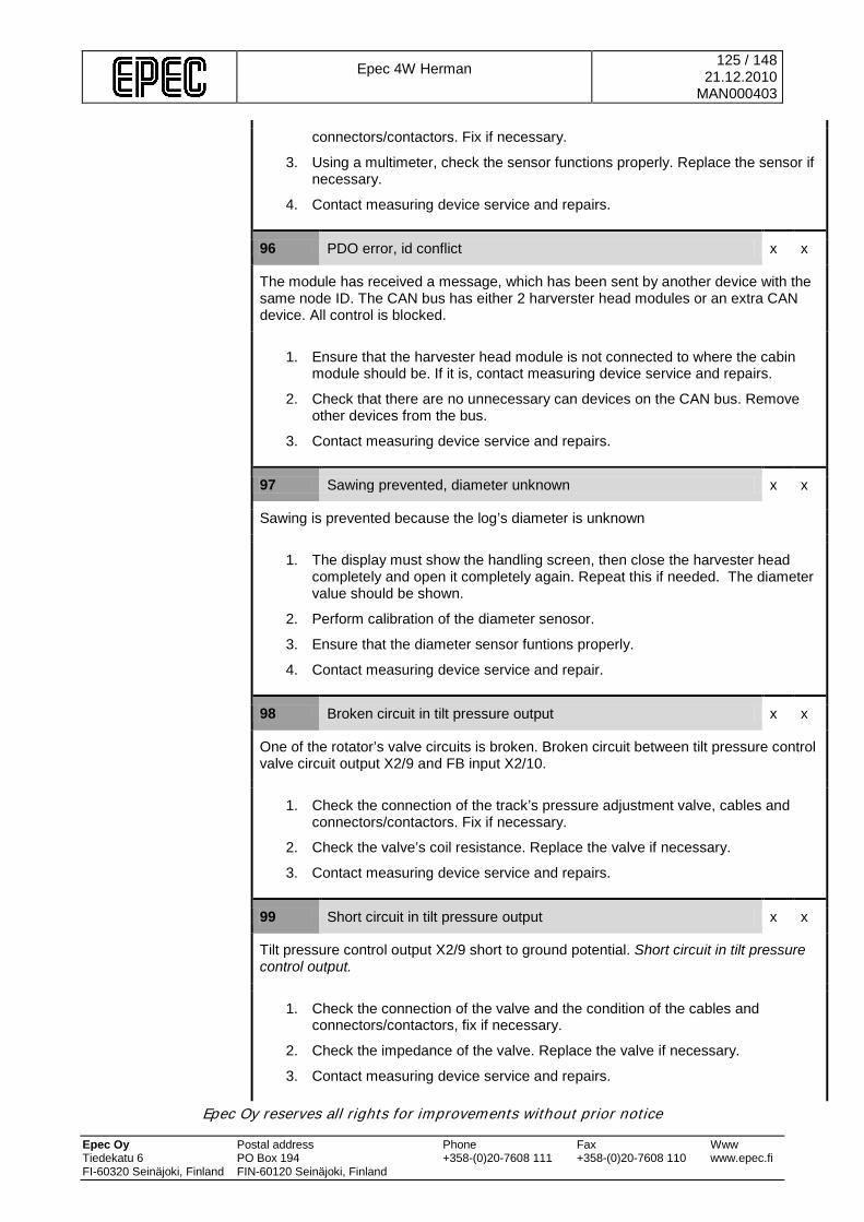
Epec 4W Herman
125 / 148 21.12.2010
MAN000403
Epec Oy reserves all rights for improvements without prior notice Epec Oy Postal address Phone Fax Www Tiedekatu 6 PO Box 194 +358-(0)20-7608 111 +358-(0)20-7608 110 www.epec.fi FI-60320 Seinäjoki, Finland FIN-60120 Seinäjoki, Finland
connectors/contactors. Fix if necessary.
3. Using a multimeter, check the sensor functions properly. Replace the sensor if necessary.
4. Contact measuring device service and repairs.
96 PDO error, id conflict x x
The module has received a message, which has been sent by another device with the same node ID. The CAN bus has either 2 harverster head modules or an extra CAN device. All control is blocked.
1. Ensure that the harvester head module is not connected to where the cabin module should be. If it is, contact measuring device service and repairs.
2. Check that there are no unnecessary can devices on the CAN bus. Remove other devices from the bus.
3. Contact measuring device service and repairs.
97 Sawing prevented, diameter unknown x x
Sawing is prevented because the log’s diameter is unknown
1. The display must show the handling screen, then close the harvester head completely and open it completely again. Repeat this if needed. The diameter value should be shown.
2. Perform calibration of the diameter senosor.
3. Ensure that the diameter sensor funtions properly.
4. Contact measuring device service and repair.
98 Broken circuit in tilt pressure output x x
One of the rotator’s valve circuits is broken. Broken circuit between tilt pressure control valve circuit output X2/9 and FB input X2/10.
1. Check the connection of the track’s pressure adjustment valve, cables and connectors/contactors. Fix if necessary.
2. Check the valve’s coil resistance. Replace the valve if necessary.
3. Contact measuring device service and repairs.
99 Short circuit in tilt pressure output x x
Tilt pressure control output X2/9 short to ground potential. Short circuit in tilt pressure control output.
1. Check the connection of the valve and the condition of the cables and connectors/contactors, fix if necessary.
2. Check the impedance of the valve. Replace the valve if necessary.
3. Contact measuring device service and repairs.
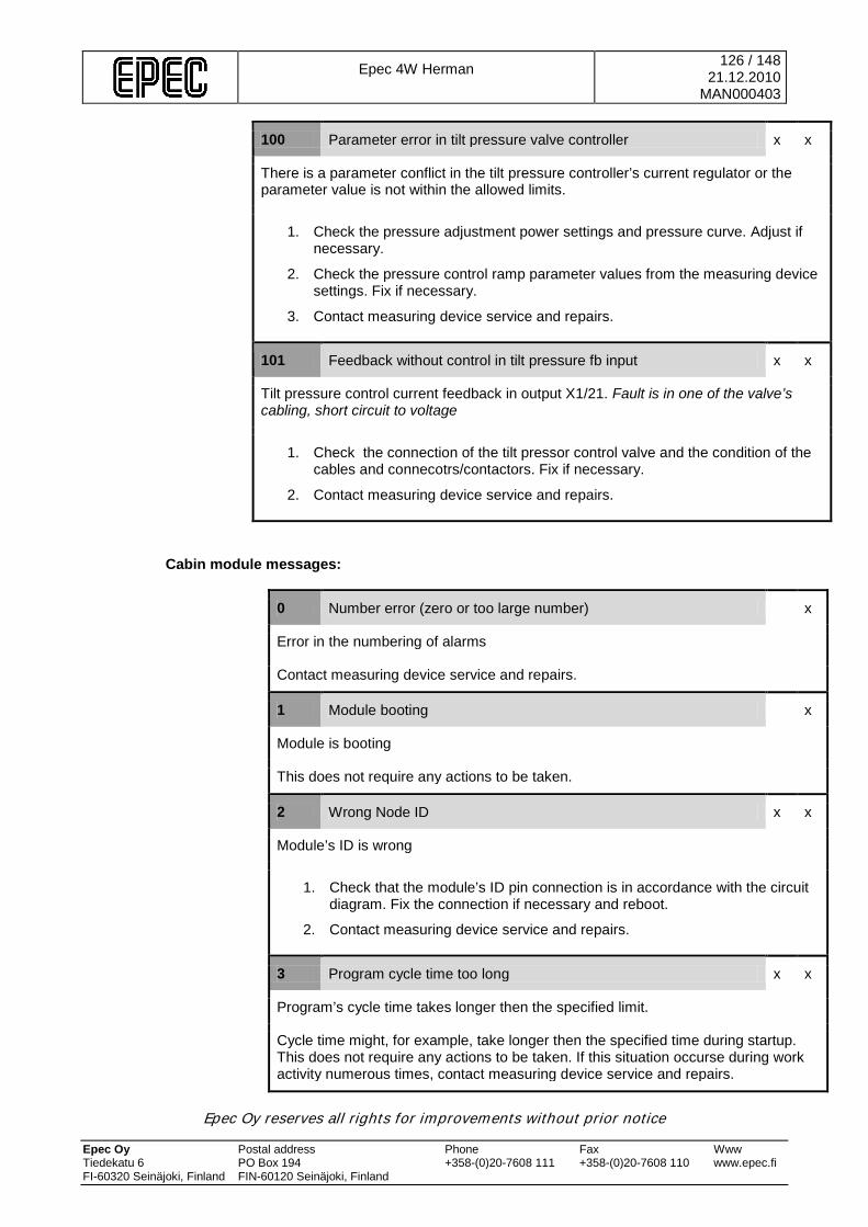
Epec 4W Herman
126 / 148 21.12.2010
MAN000403
Epec Oy reserves all rights for improvements without prior notice Epec Oy Postal address Phone Fax Www Tiedekatu 6 PO Box 194 +358-(0)20-7608 111 +358-(0)20-7608 110 www.epec.fi FI-60320 Seinäjoki, Finland FIN-60120 Seinäjoki, Finland
100 Parameter error in tilt pressure valve controller x x
There is a parameter conflict in the tilt pressure controller’s current regulator or the parameter value is not within the allowed limits.
1. Check the pressure adjustment power settings and pressure curve. Adjust if necessary.
2. Check the pressure control ramp parameter values from the measuring device settings. Fix if necessary.
3. Contact measuring device service and repairs.
101 Feedback without control in tilt pressure fb input x x
Tilt pressure control current feedback in output X1/21. Fault is in one of the valve’s cabling, short circuit to voltage
1. Check the connection of the tilt pressor control valve and the condition of the cables and connecotrs/contactors. Fix if necessary.
2. Contact measuring device service and repairs.
Cabin module messages:
0 Number error (zero or too large number) x
Error in the numbering of alarms
Contact measuring device service and repairs.
1 Module booting x
Module is booting
This does not require any actions to be taken.
2 Wrong Node ID x x
Module’s ID is wrong
1. Check that the module’s ID pin connection is in accordance with the circuit diagram. Fix the connection if necessary and reboot.
2. Contact measuring device service and repairs.
3 Program cycle time too long x x
Program’s cycle time takes longer then the specified limit.
Cycle time might, for example, take longer then the specified time during startup. This does not require any actions to be taken. If this situation occurse during work activity numerous times, contact measuring device service and repairs.
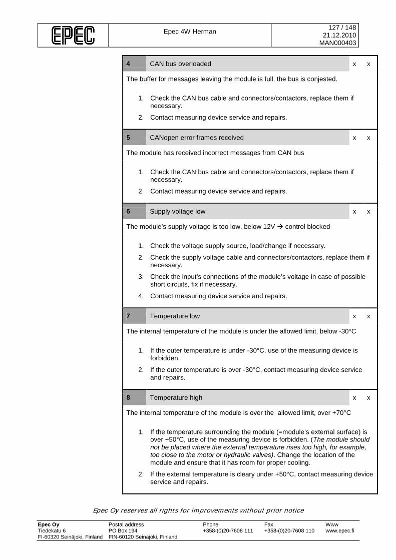
Epec 4W Herman
127 / 148 21.12.2010
MAN000403
Epec Oy reserves all rights for improvements without prior notice Epec Oy Postal address Phone Fax Www Tiedekatu 6 PO Box 194 +358-(0)20-7608 111 +358-(0)20-7608 110 www.epec.fi FI-60320 Seinäjoki, Finland FIN-60120 Seinäjoki, Finland
4 CAN bus overloaded x x
The buffer for messages leaving the module is full, the bus is conjested.
1. Check the CAN bus cable and connectors/contactors, replace them if necessary.
2. Contact measuring device service and repairs.
5 CANopen error frames received x x
The module has received incorrect messages from CAN bus
1. Check the CAN bus cable and connectors/contactors, replace them if necessary.
2. Contact measuring device service and repairs.
6 Supply voltage low x x
The module’s supply voltage is too low, below 12V control blocked
1. Check the voltage supply source, load/change if necessary.
2. Check the supply voltage cable and connectors/contactors, replace them if necessary.
3. Check the input’s connections of the module’s voltage in case of possible short circuits, fix if necessary.
4. Contact measuring device service and repairs.
7 Temperature low x x
The internal temperature of the module is under the allowed limit, below -30°C
1. If the outer temperature is under -30°C, use of the measuring device is forbidden.
2. If the outer temperature is over -30°C, contact measuring device service and repairs.
8 Temperature high x x
The internal temperature of the module is over the allowed limit, over +70°C
1. If the temperature surrounding the module (=module’s external surface) is over +50°C, use of the measuring device is forbidden. (The module should not be placed where the external temperature rises too high, for example, too close to the motor or hydraulic valves). Change the location of the module and ensure that it has room for proper cooling.
2. If the external temperature is cleary under +50°C, contact measuring device service and repairs.
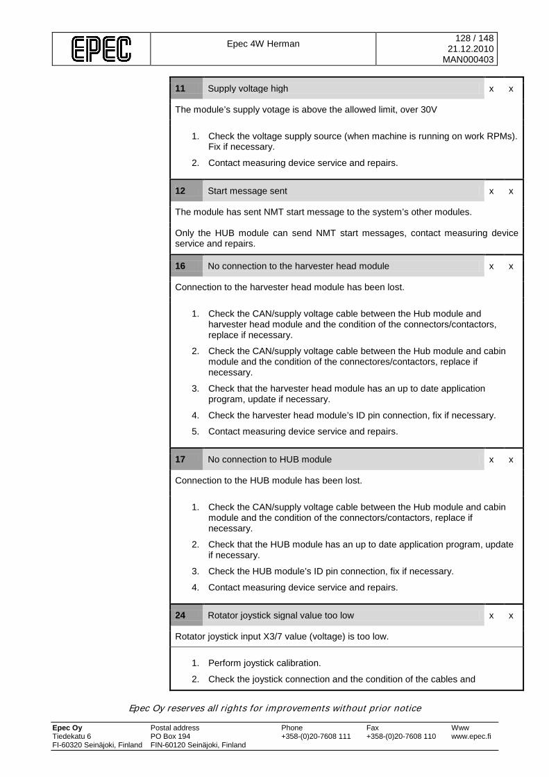
Epec 4W Herman
128 / 148 21.12.2010
MAN000403
Epec Oy reserves all rights for improvements without prior notice Epec Oy Postal address Phone Fax Www Tiedekatu 6 PO Box 194 +358-(0)20-7608 111 +358-(0)20-7608 110 www.epec.fi FI-60320 Seinäjoki, Finland FIN-60120 Seinäjoki, Finland
11 Supply voltage high x x
The module’s supply votage is above the allowed limit, over 30V
1. Check the voltage supply source (when machine is running on work RPMs). Fix if necessary.
2. Contact measuring device service and repairs.
12 Start message sent x x
The module has sent NMT start message to the system’s other modules.
Only the HUB module can send NMT start messages, contact measuring device service and repairs.
16 No connection to the harvester head module x x
Connection to the harvester head module has been lost.
1. Check the CAN/supply voltage cable between the Hub module and harvester head module and the condition of the connectors/contactors, replace if necessary.
2. Check the CAN/supply voltage cable between the Hub module and cabin module and the condition of the connectores/contactors, replace if necessary.
3. Check that the harvester head module has an up to date application program, update if necessary.
4. Check the harvester head module’s ID pin connection, fix if necessary.
5. Contact measuring device service and repairs.
17 No connection to HUB module x x
Connection to the HUB module has been lost.
1. Check the CAN/supply voltage cable between the Hub module and cabin module and the condition of the connectors/contactors, replace if necessary.
2. Check that the HUB module has an up to date application program, update if necessary.
3. Check the HUB module’s ID pin connection, fix if necessary.
4. Contact measuring device service and repairs.
24 Rotator joystick signal value too low x x
Rotator joystick input X3/7 value (voltage) is too low.
1. Perform joystick calibration.
2. Check the joystick connection and the condition of the cables and
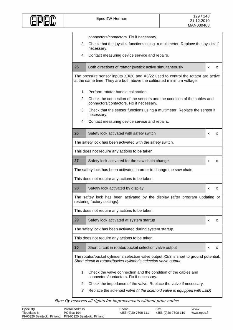
Epec 4W Herman
129 / 148 21.12.2010
MAN000403
Epec Oy reserves all rights for improvements without prior notice Epec Oy Postal address Phone Fax Www Tiedekatu 6 PO Box 194 +358-(0)20-7608 111 +358-(0)20-7608 110 www.epec.fi FI-60320 Seinäjoki, Finland FIN-60120 Seinäjoki, Finland
connectors/contactors. Fix if necessary.
3. Check that the joystick functions using a multimeter. Replace the joystick if necessary.
4. Contact measuring device service and repairs.
25 Both directions of rotator joystick active simultaneously x x
The pressure sensor inputs X3/20 and X3/22 used to control the rotator are active at the same time. They are both above the calibrated minimum voltage.
1. Perform rotator handle calibration.
2. Check the connection of the sensors and the condition of the cables and connectors/contactors. Fix if necessary.
3. Check that the sensor functions using a multimeter. Replace the sensor if necessary.
4. Contact measuring device service and repairs.
26 Safety lock activated with safety switch x x
The safety lock has been activated with the safety switch.
This does not require any actions to be taken.
27 Safety lock activated for the saw chain change x x
The safety lock has been activated in order to change the saw chain
This does not require any actions to be taken.
28 Safetly lock activated by display x x
The saftey lock has been activated by the display (after program updating or restoring factory settings).
This does not require any actions to be taken.
29 Safety lock activated at system startup x x
The safety lock has been activated during system startup.
This does not require any actions to be taken.
30 Short circuit in rotator/bucket selection valve output x x
The rotator/bucket cylinder’s selection valve output X2/3 is short to ground potential. Short circuit in rotator/bucket cylinder’s selection valve output.
1. Check the valve connection and the condition of the cables and connectors/contactors. Fix if necessary.
2. Check the impedance of the valve. Replace the valve if necessary.
3. Replace the solenoid valve (if the solenoid valve is equipped with LED)

Epec 4W Herman
130 / 148 21.12.2010
MAN000403
Epec Oy reserves all rights for improvements without prior notice Epec Oy Postal address Phone Fax Www Tiedekatu 6 PO Box 194 +358-(0)20-7608 111 +358-(0)20-7608 110 www.epec.fi FI-60320 Seinäjoki, Finland FIN-60120 Seinäjoki, Finland
4. Contact measuring device service and repairs.
31 Voltage without control in rotator/bucket selection valve output x x
Uncontrolled voltage in Rotator/bucket cylinder output X2/3. Fault is in the valve’s cabling, short circuit to voltage.
1. Check the valve connection and the condition of the cables and connectors/contactors. Fix if necessary.
2. Contact measuring device service and repairs.
32 Rotator joystick signal value too high x x
Rotator joystick input X3/7 value (voltage) is above the allowed limit.
1. Perform rotator handle calibration.
2. Check the joystick connection and the condition of the cables and connectors/contactors. Fix if necessary.
3. Check that the joystick functions using a multimeter. Replace the joystick if necessary.
4. Contact measuring device service and repairs.
33 Rotator joystick parameter error x x
There is a parameter conflict in the rotator joystick or the parameter value is not within the allowed limits.
1. Perform rotator handle calibration.
2. Check the joystick parameters from the measuring device settings (progression, dead band). Modify if necessary.
3. Contact measuring device service and repairs.
34 Rotator joystick’s positive direction signal too high x x
Rotator clockwise pressure sensor input X3/20 value (voltage) is above the allowed limit.
1. Perform rotator handle calibration.
2. Check the pressure sensor connection and the condition of the cables and connectors/contactors. Fix if necessary.
3. Check that the pressure sensor functions using a multimeter. Replace the sensor if necessary.
4. Contact measuring device service and repairs.
35 Rotator joystick’s positive direction signal too low x x
Rotator clockwise pressure sensor input X3/20 value (voltage) is below the allowed limit.

Epec 4W Herman
131 / 148 21.12.2010
MAN000403
Epec Oy reserves all rights for improvements without prior notice Epec Oy Postal address Phone Fax Www Tiedekatu 6 PO Box 194 +358-(0)20-7608 111 +358-(0)20-7608 110 www.epec.fi FI-60320 Seinäjoki, Finland FIN-60120 Seinäjoki, Finland
1. Perform rotator handle calibration.
2. Check the pressure sensor connection and the condition of the cables and connectors/contactors. Fix if necessary.
3. Check that the pressure sensor functions using a multimeter. Replace the sensor if necessary.
4. Contact measuring device service and repairs.
36 Rotator joystick’s negative direction signal too high x x
Rotator counter clockwise pressure sensor input X3/22 value (voltage) is above the allowed limit.
1. Perform rotator handle calibration.
2. Check the pressure sensor connection and the condition of the cables and connectors/contactors. Fix if necessary.
3. Check that the pressure sensor functions using a multimeter. Replace the sensor if necessary.
4. Contact measuring device service and repairs.
37 Rotator joystick’s negative direction signal too low x x
Rotator counter clockwise pressure sensor input X3/22 value (voltage) is below the allowed limit.
1. Perform rotator handle calibration.
2. Check the pressure sensor connection and the condition of the cables and connectors/contactors. Fix if necessary.
3. Check that the pressure sensor functions using a multimeter. Replace the sensor if necessary.
4. Contact measuring device service and repairs.
38 Rotator handle parameter error x x
There is a parameter conflict in the rotator handle or the parameter value is not within the allowed limits.
1. Perform rotator handle calibration.
2. Check the handle parameters from the measruing device setting (progression, dead band). Modify if necessary.
3. Contact measuring device service and repairs.
40 Button pressed during safety switch release x x
A button was pressed while the safety switch was being released. The safety bar was lifted and the state of the chair’s limit switch changed or the state of the limit changed when the door closed.
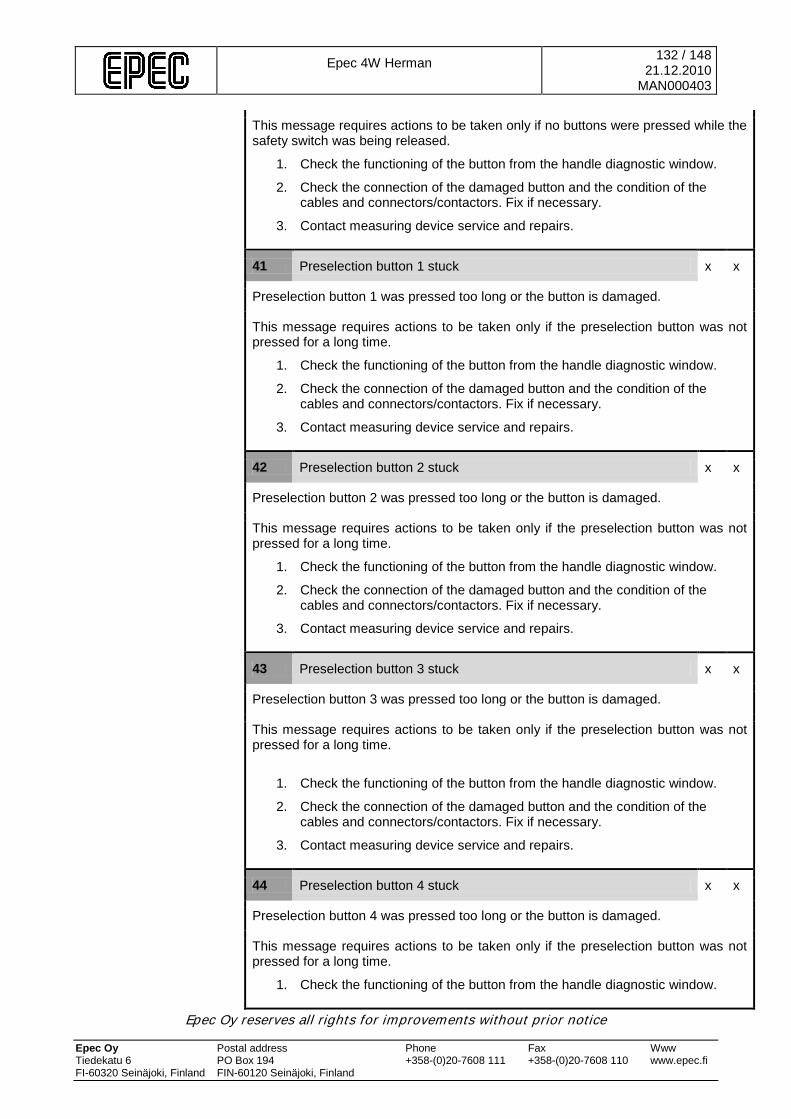
Epec 4W Herman
132 / 148 21.12.2010
MAN000403
Epec Oy reserves all rights for improvements without prior notice Epec Oy Postal address Phone Fax Www Tiedekatu 6 PO Box 194 +358-(0)20-7608 111 +358-(0)20-7608 110 www.epec.fi FI-60320 Seinäjoki, Finland FIN-60120 Seinäjoki, Finland
This message requires actions to be taken only if no buttons were pressed while the safety switch was being released.
1. Check the functioning of the button from the handle diagnostic window.
2. Check the connection of the damaged button and the condition of the cables and connectors/contactors. Fix if necessary.
3. Contact measuring device service and repairs.
41 Preselection button 1 stuck x x
Preselection button 1 was pressed too long or the button is damaged.
This message requires actions to be taken only if the preselection button was not pressed for a long time.
1. Check the functioning of the button from the handle diagnostic window.
2. Check the connection of the damaged button and the condition of the cables and connectors/contactors. Fix if necessary.
3. Contact measuring device service and repairs.
42 Preselection button 2 stuck x x
Preselection button 2 was pressed too long or the button is damaged.
This message requires actions to be taken only if the preselection button was not pressed for a long time.
1. Check the functioning of the button from the handle diagnostic window.
2. Check the connection of the damaged button and the condition of the cables and connectors/contactors. Fix if necessary.
3. Contact measuring device service and repairs.
43 Preselection button 3 stuck x x
Preselection button 3 was pressed too long or the button is damaged.
This message requires actions to be taken only if the preselection button was not pressed for a long time.
1. Check the functioning of the button from the handle diagnostic window.
2. Check the connection of the damaged button and the condition of the cables and connectors/contactors. Fix if necessary.
3. Contact measuring device service and repairs.
44 Preselection button 4 stuck x x
Preselection button 4 was pressed too long or the button is damaged.
This message requires actions to be taken only if the preselection button was not pressed for a long time.
1. Check the functioning of the button from the handle diagnostic window.

Epec 4W Herman
133 / 148 21.12.2010
MAN000403
Epec Oy reserves all rights for improvements without prior notice Epec Oy Postal address Phone Fax Www Tiedekatu 6 PO Box 194 +358-(0)20-7608 111 +358-(0)20-7608 110 www.epec.fi FI-60320 Seinäjoki, Finland FIN-60120 Seinäjoki, Finland
2. Check the connection of the damaged button and the condition of the cables and connectors/contactors. Fix if necessary.
3. Contact measuring device service and repairs.
45 Preselection button 5 stuck x x
Preselection button 5 was pressed too long or the button is damaged.
This message requires actions to be taken only if the preselection button was not pressed for a long time.
1. Check the functioning of the button from the handle diagnostic window.
2. Check the connection of the damaged button and the condition of the cables and connectors/contactors. Fix if necessary.
3. Contact measuring device service and repairs.
46 Preselection button 6 stuck x x
Preselection button 6 was pressed too long or the button is damaged.
This message requires actions to be taken only if the preselection button was not pressed for a long time.
1. Check the functioning of the button from the handle diagnostic window.
2. Check the connection of the damaged button and the condition of the cables and connectors/contactors. Fix if necessary.
3. Contact measuring device service and repairs.
47 Preselection button 7 stuck x x
Preselection button 7 was pressed too long or the button is damaged.
This message requires actions to be taken only if the preselection button was not pressed for a long time.
1. Check the functioning of the button from the handle diagnostic window.
2. Check the connection of the damaged button and the condition of the cables and connectors/contactors. Fix if necessary.
3. Contact measuring device service and repairs.
48 Preselection button 8 stuck x x
Preselection button 8 was pressed too long or the button is damaged.
This message requires actions to be taken only if the preselection button was not pressed for a long time.
1. Check the functioning of the button from the handle diagnostic window.
2. Check the connection of the damaged button and the condition of the cables and connectors/contactors. Fix if necessary.
3. Contact measuring device service and repairs.

Epec 4W Herman
134 / 148 21.12.2010
MAN000403
Epec Oy reserves all rights for improvements without prior notice Epec Oy Postal address Phone Fax Www Tiedekatu 6 PO Box 194 +358-(0)20-7608 111 +358-(0)20-7608 110 www.epec.fi FI-60320 Seinäjoki, Finland FIN-60120 Seinäjoki, Finland
49 Preselection button 9 stuck x x
Preselection button 9 was pressed too long or the button is damaged.
This message requires actions to be taken only if the preselection button was not pressed for a long time.
1. Check the functioning of the button from the handle diagnostic window.
2. Check the connection of the damaged button and the condition of the cables and connectors/contactors. Fix if necessary.
3. Contact measuring device service and repairs.
50 Preselection button 10 stuck x x
Preselection button 10 was pressed too long or the button is damaged.
This message requires actions to be taken only if the preselection button was not pressed for a long time.
1. Check the functioning of the button from the handle diagnostic window.
2. Check the connection of the damaged button and the condition of the cables and connectors/contactors. Fix if necessary.
3. Contact measuring device service and repairs.
51 Programming wheel Ok button stuck x x
Programming wheel OK button was pressed too long or the button is damaged.
This message requires actions to be taken only if the preselection button was not pressed for a long time.
1. Check the functioning of the button from the handle diagnostic window.
2. Check the connection of the damaged button and the condition of the cables and connectors/contactors. Fix if necessary.
3. Contact measuring device service and repairs.
52 Programming wheel Cancel button stuck x x
Programming wheel CANCEL button was pressed too long or the button is damaged.
This message requires actions to be taken only if the preselection button was not pressed for a long time.
1. Check the functioning of the button from the handle diagnostic window.
2. Check the connection of the damaged button and the condition of the cables and connectors/contactors. Fix if necessary.
3. Contact measuring device service and repairs.
53 Safetylock button combination pressed too long x x
The button combination used to release the safety lock (Shift+harvester head close) was pressed too long or one of the buttons is damaged.
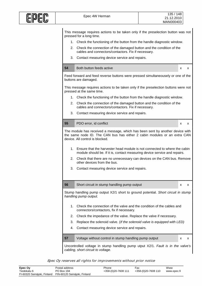
Epec 4W Herman
135 / 148 21.12.2010
MAN000403
Epec Oy reserves all rights for improvements without prior notice Epec Oy Postal address Phone Fax Www Tiedekatu 6 PO Box 194 +358-(0)20-7608 111 +358-(0)20-7608 110 www.epec.fi FI-60320 Seinäjoki, Finland FIN-60120 Seinäjoki, Finland
This message requires actions to be taken only if the preselection button was not pressed for a long time.
1. Check the functioning of the button from the handle diagnostic window.
2. Check the connection of the damaged button and the condition of the cables and connectors/contactors. Fix if necessary.
3. Contact measuring device service and repairs.
54 Both button feeds active x x
Feed forward and feed reverse buttons were pressed simultaneousely or one of the buttons are damaged.
This message requires actions to be taken only if the preselection buttons were not pressed at the same time.
1. Check the functioning of the button from the handle diagnostic window.
2. Check the connection of the damaged button and the condition of the cables and connectors/contactors. Fix if necessary.
3. Contact measuring device service and repairs.
55 PDO error, id conflict x x
The module has received a message, which has been sent by another device with the same node ID. The CAN bus has either 2 cabin modules or an extra CAN device. All control is blocked.
1. Ensure that the harvester head module is not connected to where the cabin module should be. If it is, contact measuring device service and repairs.
2. Check that there are no unnecessary can devices on the CAN bus. Remove other devices from the bus.
3. Contact measuring device service and repairs.
56 Short circuit in stump handling pump output x x
Stump handling pump output X2/1 short to ground potential. Short circuit in stump handling pump output.
1. Check the connection of the valve and the condition of the cables and connectors/contactors, fix if necessary.
2. Check the impedance of the valve. Replace the valve if necessary.
3. Replace the solenoid valve. (If the solenoid valve is equipped with LED)
4. Contact measuring device service and repairs.
57 Voltage without control in stump handling pump output x x
Uncontrolled voltage in stump handling pump utput X2/1. Fault is in the valve’s cabling, short circuit to voltage.
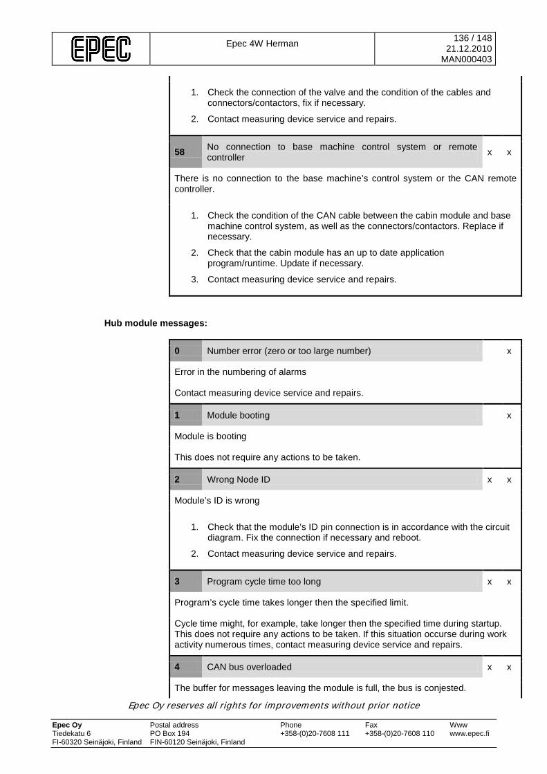
Epec 4W Herman
136 / 148 21.12.2010
MAN000403
Epec Oy reserves all rights for improvements without prior notice Epec Oy Postal address Phone Fax Www Tiedekatu 6 PO Box 194 +358-(0)20-7608 111 +358-(0)20-7608 110 www.epec.fi FI-60320 Seinäjoki, Finland FIN-60120 Seinäjoki, Finland
1. Check the connection of the valve and the condition of the cables and connectors/contactors, fix if necessary.
2. Contact measuring device service and repairs.
58 No connection to base machine control system or remote controller x x
There is no connection to the base machine’s control system or the CAN remote controller.
1. Check the condition of the CAN cable between the cabin module and base machine control system, as well as the connectors/contactors. Replace if necessary.
2. Check that the cabin module has an up to date application program/runtime. Update if necessary.
3. Contact measuring device service and repairs.
Hub module messages:
0 Number error (zero or too large number) x
Error in the numbering of alarms
Contact measuring device service and repairs.
1 Module booting x
Module is booting
This does not require any actions to be taken.
2 Wrong Node ID x x
Module’s ID is wrong
1. Check that the module’s ID pin connection is in accordance with the circuit diagram. Fix the connection if necessary and reboot.
2. Contact measuring device service and repairs.
3 Program cycle time too long x x
Program’s cycle time takes longer then the specified limit.
Cycle time might, for example, take longer then the specified time during startup. This does not require any actions to be taken. If this situation occurse during work activity numerous times, contact measuring device service and repairs.
4 CAN bus overloaded x x
The buffer for messages leaving the module is full, the bus is conjested.
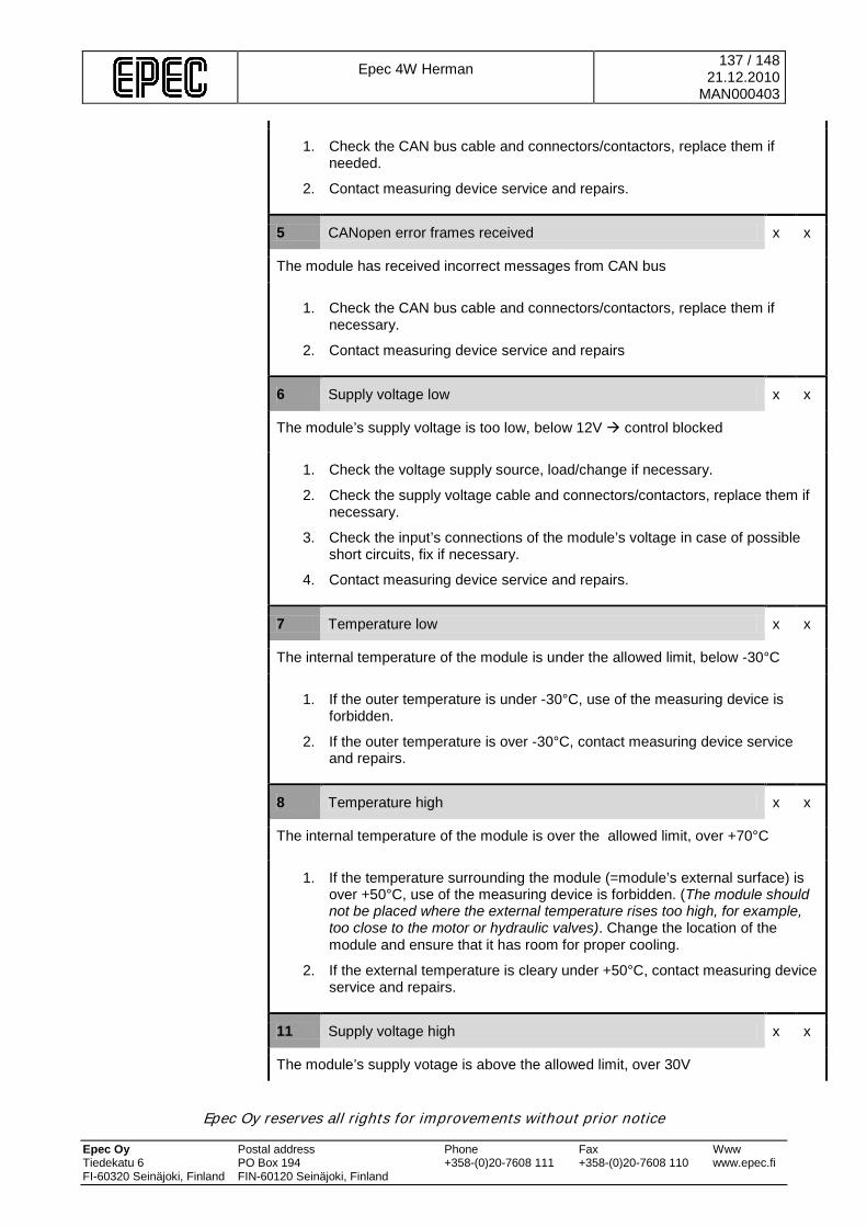
Epec 4W Herman
137 / 148 21.12.2010
MAN000403
Epec Oy reserves all rights for improvements without prior notice Epec Oy Postal address Phone Fax Www Tiedekatu 6 PO Box 194 +358-(0)20-7608 111 +358-(0)20-7608 110 www.epec.fi FI-60320 Seinäjoki, Finland FIN-60120 Seinäjoki, Finland
1. Check the CAN bus cable and connectors/contactors, replace them if needed.
2. Contact measuring device service and repairs.
5 CANopen error frames received x x
The module has received incorrect messages from CAN bus
1. Check the CAN bus cable and connectors/contactors, replace them if necessary.
2. Contact measuring device service and repairs
6 Supply voltage low x x
The module’s supply voltage is too low, below 12V control blocked
1. Check the voltage supply source, load/change if necessary.
2. Check the supply voltage cable and connectors/contactors, replace them if necessary.
3. Check the input’s connections of the module’s voltage in case of possible short circuits, fix if necessary.
4. Contact measuring device service and repairs.
7 Temperature low x x
The internal temperature of the module is under the allowed limit, below -30°C
1. If the outer temperature is under -30°C, use of the measuring device is forbidden.
2. If the outer temperature is over -30°C, contact measuring device service and repairs.
8 Temperature high x x
The internal temperature of the module is over the allowed limit, over +70°C
1. If the temperature surrounding the module (=module’s external surface) is over +50°C, use of the measuring device is forbidden. (The module should not be placed where the external temperature rises too high, for example, too close to the motor or hydraulic valves). Change the location of the module and ensure that it has room for proper cooling.
2. If the external temperature is cleary under +50°C, contact measuring device service and repairs.
11 Supply voltage high x x
The module’s supply votage is above the allowed limit, over 30V

Epec 4W Herman
138 / 148 21.12.2010
MAN000403
Epec Oy reserves all rights for improvements without prior notice Epec Oy Postal address Phone Fax Www Tiedekatu 6 PO Box 194 +358-(0)20-7608 111 +358-(0)20-7608 110 www.epec.fi FI-60320 Seinäjoki, Finland FIN-60120 Seinäjoki, Finland
1. Check the voltage supply source (when machine is running on work RPMs), fix if necessary.
2. Contact measuring device service and repairs.
12 Start message sent x x
The module has sent NMT start message to the system’s other modules.
If the module sends NMT start messages after the measuring device is booted (voltage connection), it means that the Hub module has rebooted for some reason, for example, becuase the supply votage break. (the Hub module can send NMT start messages, for example, during program updating because the display reboots the modules during program updating.
1. Check the condition of the Hub module’s CAN/supply voltage cable and connectors/contactors. Replace if necessary.
2. Contact measuring device service and repairs.
16 No connection to harvester head module x x
Connection to the harvester head module has been lost.
1. Check the CAN/supply voltage cable between the Hub module and harvester head module and the condition of the connectors/contactors. Replace if necessary.
2. Check that the harvester head module has an up to date application program. Update if necessary.
3. Check the harvester head module’s ID pin connection. Fix if necessary.
4. Contact measuring device service and repairs.
17 No connection to cabin module x x
Connection to the cabin module has been lost.
1. Check the CAN/supply voltage cable between the Hub module and cabin module and the condition of the connectors/contactors. Replace if necessary.
2. Check that the cabin module has an up to date application program. Update if necessary.
3. Check the cabin module’s ID pin connection. Fix if necessary.
4. Contact measuring device service and repairs.
24 Hub module X1 connector current over alarm limit x x
Hub module connector X1 current is above the allowed limit
1. Check the supply voltage of the modules connected to connector X1. Also check the condition of the cables and connectors/contactors. Fix if necessary.
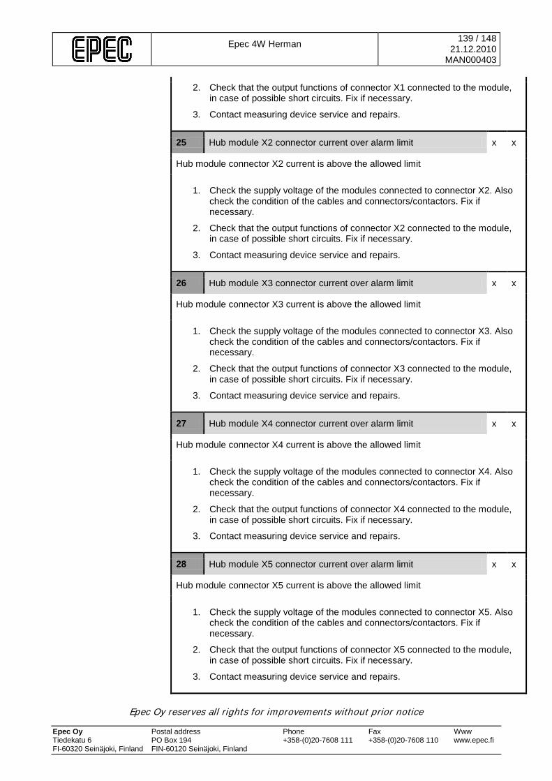
Epec 4W Herman
139 / 148 21.12.2010
MAN000403
Epec Oy reserves all rights for improvements without prior notice Epec Oy Postal address Phone Fax Www Tiedekatu 6 PO Box 194 +358-(0)20-7608 111 +358-(0)20-7608 110 www.epec.fi FI-60320 Seinäjoki, Finland FIN-60120 Seinäjoki, Finland
2. Check that the output functions of connector X1 connected to the module, in case of possible short circuits. Fix if necessary.
3. Contact measuring device service and repairs.
25 Hub module X2 connector current over alarm limit x x
Hub module connector X2 current is above the allowed limit
1. Check the supply voltage of the modules connected to connector X2. Also check the condition of the cables and connectors/contactors. Fix if necessary.
2. Check that the output functions of connector X2 connected to the module, in case of possible short circuits. Fix if necessary.
3. Contact measuring device service and repairs.
26 Hub module X3 connector current over alarm limit x x
Hub module connector X3 current is above the allowed limit
1. Check the supply voltage of the modules connected to connector X3. Also check the condition of the cables and connectors/contactors. Fix if necessary.
2. Check that the output functions of connector X3 connected to the module, in case of possible short circuits. Fix if necessary.
3. Contact measuring device service and repairs.
27 Hub module X4 connector current over alarm limit x x
Hub module connector X4 current is above the allowed limit
1. Check the supply voltage of the modules connected to connector X4. Also check the condition of the cables and connectors/contactors. Fix if necessary.
2. Check that the output functions of connector X4 connected to the module, in case of possible short circuits. Fix if necessary.
3. Contact measuring device service and repairs.
28 Hub module X5 connector current over alarm limit x x
Hub module connector X5 current is above the allowed limit
1. Check the supply voltage of the modules connected to connector X5. Also check the condition of the cables and connectors/contactors. Fix if necessary.
2. Check that the output functions of connector X5 connected to the module, in case of possible short circuits. Fix if necessary.
3. Contact measuring device service and repairs.
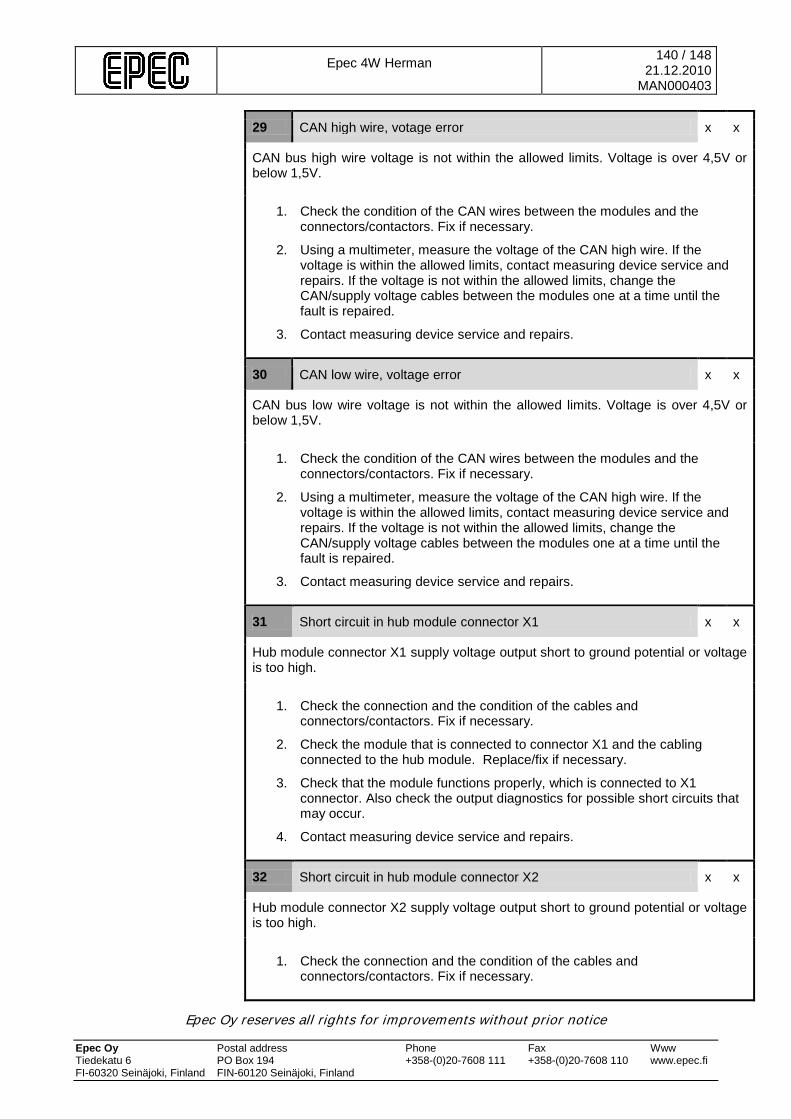
Epec 4W Herman
140 / 148 21.12.2010
MAN000403
Epec Oy reserves all rights for improvements without prior notice Epec Oy Postal address Phone Fax Www Tiedekatu 6 PO Box 194 +358-(0)20-7608 111 +358-(0)20-7608 110 www.epec.fi FI-60320 Seinäjoki, Finland FIN-60120 Seinäjoki, Finland
29 CAN high wire, votage error x x
CAN bus high wire voltage is not within the allowed limits. Voltage is over 4,5V or below 1,5V.
1. Check the condition of the CAN wires between the modules and the connectors/contactors. Fix if necessary.
2. Using a multimeter, measure the voltage of the CAN high wire. If the voltage is within the allowed limits, contact measuring device service and repairs. If the voltage is not within the allowed limits, change the CAN/supply voltage cables between the modules one at a time until the fault is repaired.
3. Contact measuring device service and repairs.
30 CAN low wire, voltage error x x
CAN bus low wire voltage is not within the allowed limits. Voltage is over 4,5V or below 1,5V.
1. Check the condition of the CAN wires between the modules and the connectors/contactors. Fix if necessary.
2. Using a multimeter, measure the voltage of the CAN high wire. If the voltage is within the allowed limits, contact measuring device service and repairs. If the voltage is not within the allowed limits, change the CAN/supply voltage cables between the modules one at a time until the fault is repaired.
3. Contact measuring device service and repairs.
31 Short circuit in hub module connector X1 x x
Hub module connector X1 supply voltage output short to ground potential or voltage is too high.
1. Check the connection and the condition of the cables and connectors/contactors. Fix if necessary.
2. Check the module that is connected to connector X1 and the cabling connected to the hub module. Replace/fix if necessary.
3. Check that the module functions properly, which is connected to X1 connector. Also check the output diagnostics for possible short circuits that may occur.
4. Contact measuring device service and repairs.
32 Short circuit in hub module connector X2 x x
Hub module connector X2 supply voltage output short to ground potential or voltage is too high.
1. Check the connection and the condition of the cables and connectors/contactors. Fix if necessary.
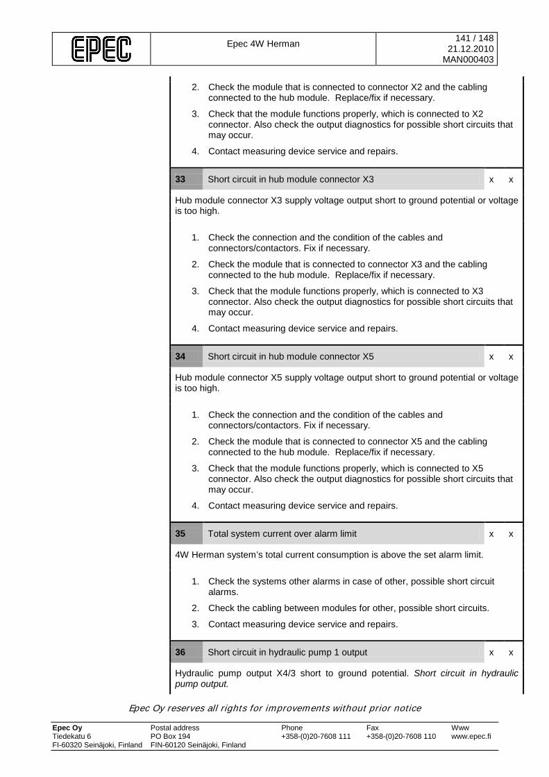
Epec 4W Herman
141 / 148 21.12.2010
MAN000403
Epec Oy reserves all rights for improvements without prior notice Epec Oy Postal address Phone Fax Www Tiedekatu 6 PO Box 194 +358-(0)20-7608 111 +358-(0)20-7608 110 www.epec.fi FI-60320 Seinäjoki, Finland FIN-60120 Seinäjoki, Finland
2. Check the module that is connected to connector X2 and the cabling connected to the hub module. Replace/fix if necessary.
3. Check that the module functions properly, which is connected to X2 connector. Also check the output diagnostics for possible short circuits that may occur.
4. Contact measuring device service and repairs.
33 Short circuit in hub module connector X3 x x
Hub module connector X3 supply voltage output short to ground potential or voltage is too high.
1. Check the connection and the condition of the cables and connectors/contactors. Fix if necessary.
2. Check the module that is connected to connector X3 and the cabling connected to the hub module. Replace/fix if necessary.
3. Check that the module functions properly, which is connected to X3 connector. Also check the output diagnostics for possible short circuits that may occur.
4. Contact measuring device service and repairs.
34 Short circuit in hub module connector X5 x x
Hub module connector X5 supply voltage output short to ground potential or voltage is too high.
1. Check the connection and the condition of the cables and connectors/contactors. Fix if necessary.
2. Check the module that is connected to connector X5 and the cabling connected to the hub module. Replace/fix if necessary.
3. Check that the module functions properly, which is connected to X5 connector. Also check the output diagnostics for possible short circuits that may occur.
4. Contact measuring device service and repairs.
35 Total system current over alarm limit x x
4W Herman system’s total current consumption is above the set alarm limit.
1. Check the systems other alarms in case of other, possible short circuit alarms.
2. Check the cabling between modules for other, possible short circuits.
3. Contact measuring device service and repairs.
36 Short circuit in hydraulic pump 1 output x x
Hydraulic pump output X4/3 short to ground potential. Short circuit in hydraulic pump output.
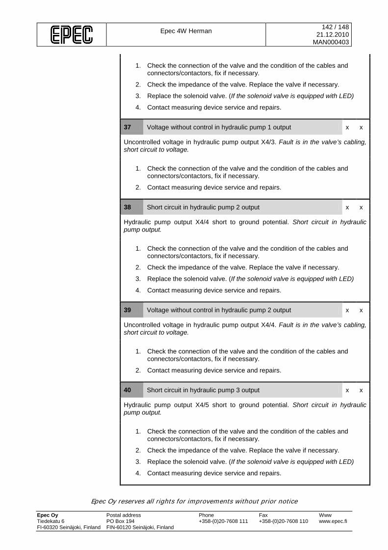
Epec 4W Herman
142 / 148 21.12.2010
MAN000403
Epec Oy reserves all rights for improvements without prior notice Epec Oy Postal address Phone Fax Www Tiedekatu 6 PO Box 194 +358-(0)20-7608 111 +358-(0)20-7608 110 www.epec.fi FI-60320 Seinäjoki, Finland FIN-60120 Seinäjoki, Finland
1. Check the connection of the valve and the condition of the cables and connectors/contactors, fix if necessary.
2. Check the impedance of the valve. Replace the valve if necessary.
3. Replace the solenoid valve. (If the solenoid valve is equipped with LED)
4. Contact measuring device service and repairs.
37 Voltage without control in hydraulic pump 1 output x x
Uncontrolled voltage in hydraulic pump output X4/3. Fault is in the valve’s cabling, short circuit to voltage.
1. Check the connection of the valve and the condition of the cables and connectors/contactors, fix if necessary.
2. Contact measuring device service and repairs.
38 Short circuit in hydraulic pump 2 output x x
Hydraulic pump output X4/4 short to ground potential. Short circuit in hydraulic pump output.
1. Check the connection of the valve and the condition of the cables and connectors/contactors, fix if necessary.
2. Check the impedance of the valve. Replace the valve if necessary.
3. Replace the solenoid valve. (If the solenoid valve is equipped with LED)
4. Contact measuring device service and repairs.
39 Voltage without control in hydraulic pump 2 output x x
Uncontrolled voltage in hydraulic pump output X4/4. Fault is in the valve’s cabling, short circuit to voltage.
1. Check the connection of the valve and the condition of the cables and connectors/contactors, fix if necessary.
2. Contact measuring device service and repairs.
40 Short circuit in hydraulic pump 3 output x x
Hydraulic pump output X4/5 short to ground potential. Short circuit in hydraulic pump output.
1. Check the connection of the valve and the condition of the cables and connectors/contactors, fix if necessary.
2. Check the impedance of the valve. Replace the valve if necessary.
3. Replace the solenoid valve. (If the solenoid valve is equipped with LED)
4. Contact measuring device service and repairs.

Epec 4W Herman
143 / 148 21.12.2010
MAN000403
Epec Oy reserves all rights for improvements without prior notice Epec Oy Postal address Phone Fax Www Tiedekatu 6 PO Box 194 +358-(0)20-7608 111 +358-(0)20-7608 110 www.epec.fi FI-60320 Seinäjoki, Finland FIN-60120 Seinäjoki, Finland
41 Voltage without control in hydraulic pump 3 output x x
Uncontrolled voltage in hydraulic pump output X4/5. Fault is in the valve’s cabling, short circuit to voltage.
1. Check the connection of the valve and the condition of the cables and connectors/contactors, fix if necessary.
2. Contact measuring device service and repairs.
42 Manual bypass mode x x
The system’s manual bypass has been activated.
1. Contact measuring device services and repairs.
43 PDO error, id conflict x x
The module has received a message, which has been sent by another device with the same node ID. The CAN bus has either 2 cabin modules or an extra CAN device. All control is blocked.
1. Check that there are no unnecessary can devices on the CAN bus. Remove other devices from the bus.
2. Contact measuring device service and repairs.
44 Duplicated safety switch status conflict x x
Duplicated safety switch is activated but the safety switch states are in conflict. The safety switches are not in the same position.
1. Check that the safety switch is functioning and check the cabling. Fix if necessary.
2. Contact measuring device service and repairs.
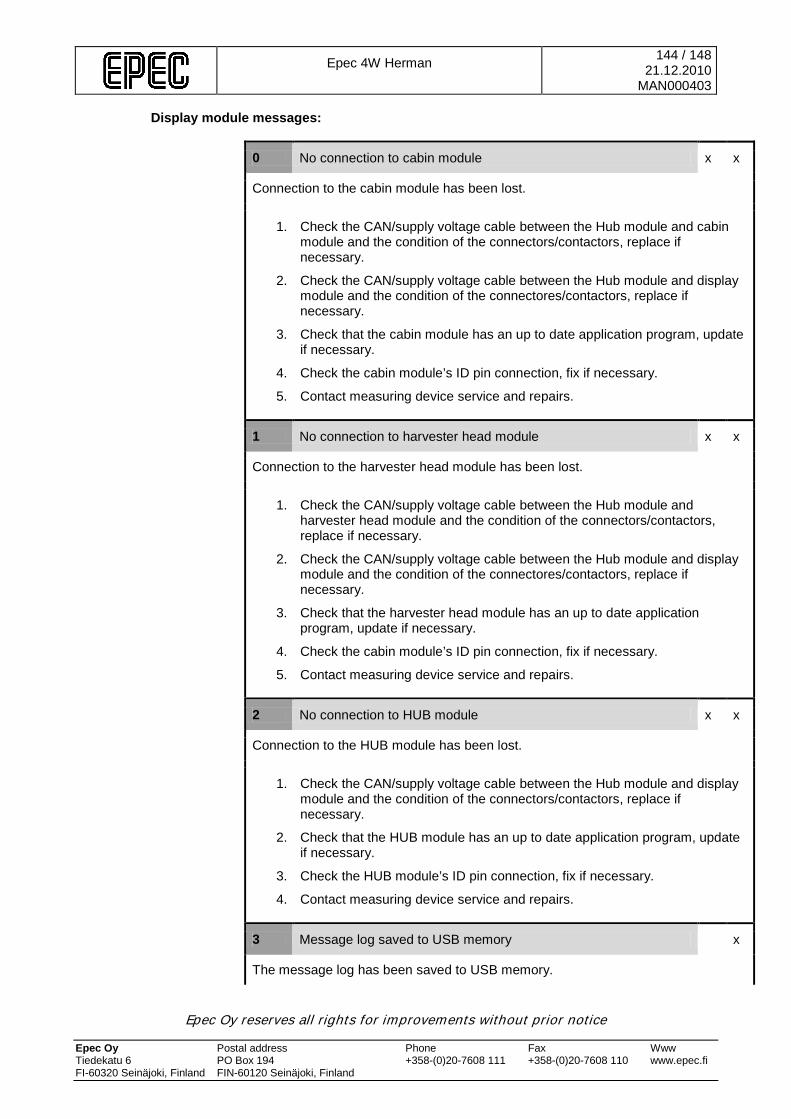
Epec 4W Herman
144 / 148 21.12.2010
MAN000403
Epec Oy reserves all rights for improvements without prior notice Epec Oy Postal address Phone Fax Www Tiedekatu 6 PO Box 194 +358-(0)20-7608 111 +358-(0)20-7608 110 www.epec.fi FI-60320 Seinäjoki, Finland FIN-60120 Seinäjoki, Finland
Display module messages:
0 No connection to cabin module x x
Connection to the cabin module has been lost.
1. Check the CAN/supply voltage cable between the Hub module and cabin module and the condition of the connectors/contactors, replace if necessary.
2. Check the CAN/supply voltage cable between the Hub module and display module and the condition of the connectores/contactors, replace if necessary.
3. Check that the cabin module has an up to date application program, update if necessary.
4. Check the cabin module’s ID pin connection, fix if necessary.
5. Contact measuring device service and repairs.
1 No connection to harvester head module x x
Connection to the harvester head module has been lost.
1. Check the CAN/supply voltage cable between the Hub module and harvester head module and the condition of the connectors/contactors, replace if necessary.
2. Check the CAN/supply voltage cable between the Hub module and display module and the condition of the connectores/contactors, replace if necessary.
3. Check that the harvester head module has an up to date application program, update if necessary.
4. Check the cabin module’s ID pin connection, fix if necessary.
5. Contact measuring device service and repairs.
2 No connection to HUB module x x
Connection to the HUB module has been lost.
1. Check the CAN/supply voltage cable between the Hub module and display module and the condition of the connectors/contactors, replace if necessary.
2. Check that the HUB module has an up to date application program, update if necessary.
3. Check the HUB module’s ID pin connection, fix if necessary.
4. Contact measuring device service and repairs.
3 Message log saved to USB memory x
The message log has been saved to USB memory.
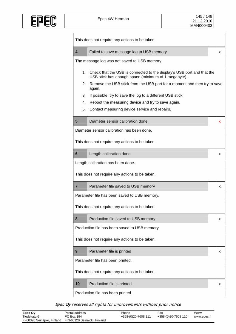
Epec 4W Herman
145 / 148 21.12.2010
MAN000403
Epec Oy reserves all rights for improvements without prior notice Epec Oy Postal address Phone Fax Www Tiedekatu 6 PO Box 194 +358-(0)20-7608 111 +358-(0)20-7608 110 www.epec.fi FI-60320 Seinäjoki, Finland FIN-60120 Seinäjoki, Finland
This does not require any actions to be taken.
4 Failed to save message log to USB memory x
The message log was not saved to USB memory
1. Check that the USB is connected to the display’s USB port and that the USB stick has enough space (minimum of 1 megabyte).
2. Remove the USB stick from the USB port for a moment and then try to save again.
3. If possible, try to save the log to a different USB stick.
4. Reboot the measuring device and try to save again.
5. Contact measuring device service and repairs.
5 Diameter sensor calibration done. x
Diameter sensor calibration has been done.
This does not require any actions to be taken.
6 Length calibration done. x
Length calibration has been done.
This does not require any actions to be taken.
7 Parameter file saved to USB memory x
Parameter file has been saved to USB memory.
This does not require any actions to be taken.
8 Production file saved to USB memory x
Production file has been saved to USB memory.
This does not require any actions to be taken.
9 Parameter file is printed x
Parameter file has been printed.
This does not require any actions to be taken.
10 Production file is printed x
Production file has been printed.

Epec 4W Herman
146 / 148 21.12.2010
MAN000403
Epec Oy reserves all rights for improvements without prior notice Epec Oy Postal address Phone Fax Www Tiedekatu 6 PO Box 194 +358-(0)20-7608 111 +358-(0)20-7608 110 www.epec.fi FI-60320 Seinäjoki, Finland FIN-60120 Seinäjoki, Finland
This does not require any actions to be taken.
11 Sawing prevented, no name for work area x
Sawing is prevented because the work are has not been named.
1. Create a new work area or open the work area which s not finished.
2. Contact measuring device servie and repairs.
12 Sawing prevented, work area finished x
Sawing is prevented because the selected work are is finished.
1. Create a new work area or open the work area which is not finished.
2. Contact measuring device servie and repairs.
13 Shortest target length already selected x
The shortest programmable target length has already been selected for the species of tree.
This does not require any actions to be taken.
14 Longest target length already selected x
The longest programmable target length has already been selected for the species of tree.
This does not require any actions to be taken..
15 New stem selected x
The new stem button has been pressed and the measuring device is in felling state.
This does not require any actions to be taken.
16 Length reseted x
Length has been reset. The measuring device is in sawing state.
This does not require any actions to be taken.
17 Length set x
Not in use.

Epec 4W Herman
147 / 148 21.12.2010
MAN000403
Epec Oy reserves all rights for improvements without prior notice Epec Oy Postal address Phone Fax Www Tiedekatu 6 PO Box 194 +358-(0)20-7608 111 +358-(0)20-7608 110 www.epec.fi FI-60320 Seinäjoki, Finland FIN-60120 Seinäjoki, Finland
18 Last log rejected x
The last log has been rejected and is not included in the production file (cube, length, and stem calulations)
This does not require any actions to be taken.
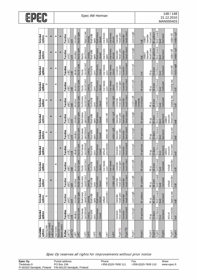
Epec 4W Herman
148 / 148 21.12.2010
MAN000403
Epec Oy reserves all rights for improvements without prior notice Epec Oy Postal address Phone Fax Www Tiedekatu 6 PO Box 194 +358-(0)20-7608 111 +358-(0)20-7608 110 www.epec.fi FI-60320 Seinäjoki, Finland FIN-60120 Seinäjoki, Finland