Embed Size (px)
Citation preview

~ePartment: System Planning and
'M°iC°" TM'"'~'s"ON °Oi~`"Y'Criteria
Strategic Projects
Document No:P LG-C R-0001-V 18
T~cie: Transmission System Planning Criteria issue gate: November 22, 2016
Previous Date: August 3, 2015
SCOPE
This document is the ATC system Planning Criteria. These criteria define systemperformance requirements. Consideration is given to ensure a safe and reliabletransmission system. These criteria address customer expectations and compliance withNERC standards. These criteria apply to the ATC transmission system operated at 69-kVand above.
This document may be revised from time to time in response to changes in industrystandards, new system conditions, new technologies and new operating procedures, asappropriate. The criteria described below will be subject to change at any time at ATC'sdiscretion. Situations that could precipitate such a change could include, but are not limitedto, new system conditions, extraordinary events, safety issues, operation issues,maintenance issues, customer requests, regulatory requirements and Regional Entity orNERC requirements.
Appr e By: Andy olan Prepared By: Curtis Roe, et alia
CAUTION: Any hard copy reproductions of this specification should be verified against the on-line system for current revisions.
ATC PLANNING CRITERIA PLN-CR-0001-V18 Planning Criteria Page 2 of 20
CAUTION: Any hard copy reproductions of this specification should be verified against the on-line system for current revisions.
1. System Performance Criteria ........................................................................................................................3
1.1 Steady State Assessments Overview ....................................................................................................3
1.1.1 Normal Intact Conditions (P0 Contingency) .................................................................................4 1.1.2 Single Contingency Conditions (P1 and P2 Contingencies) ........................................................4
1.1.3 Multiple Contingency Conditions (P3 through P7 Contingencies) ...............................................6
1.1.4 Extreme Disturbance Events (TPL-001-4 Table 1 Steady State Events) ....................................7
1.1.5 Planning Horizon Steady State Voltage Stability .........................................................................7
1.1.6 General Steady State Performance Criteria1,2 .............................................................................8
1.1.7 Contingency Definitions ...............................................................................................................9 1.2 Dynamic Stability Assessments Overview.......................................................................................... 10
1.2.1 Large Disturbance Stability Performance Assessment ............................................................. 11
1.2.2 Small Disturbance Performance Assessment ........................................................................... 12
1.2.3 Extreme Disturbance Events (NERC Standard TPL-001-4 Table 1 Stability Extreme Events) 13
1.3 Voltage Flicker .................................................................................................................................... 13
1.4 Harmonic Voltage and Current Distortion ........................................................................................... 14 1.5 Under-Frequency Load Shedding ...................................................................................................... 16
1.5.1 Island Identification.................................................................................................................... 16
1.5.2 Frequency Performance Assessment Criteria .......................................................................... 17
1.5.3 Volts Per Hertz Assessment Criteria ......................................................................................... 17
2. Variations on ATC Planning Criteria .......................................................................................................... 18
3. Administration ............................................................................................................................................ 19 3.1 Review ................................................................................................................................................ 19
3.2 Retention ............................................................................................................................................ 19
4. Revision History ......................................................................................................................................... 19
ATC PLANNING CRITERIA PLN-CR-0001-V18 Planning Criteria Page 3 of 20
CAUTION: Any hard copy reproductions of this specification should be verified against the on-line system for current revisions.
1. SYSTEM PERFORMANCE CRITERIA System performance over a ten year planning horizon will be assessed at least annually. Such assessments will involve steady state simulations and, as appropriate, dynamic simulations.
1.1 Steady State Assessments Overview Steady state assessments include the consideration of the following system load conditions.
1) Summer peak 2) Summer 90/10 proxy peak 3) Summer off-peak 4) Winter peak 5) Fall/spring off-peak 6) Light load 7) Minimum load
At a minimum, two of the first three load conditions or similar models will be assessed in all long-range planning studies. The last four load conditions may be considered when more detailed analyses are being conducted of specific alternatives developed to solve a particular problem. The steady state load conditions have the following general applications.
1) Summer peak - Used to determine summer peak load serving and regional supply limitations, including voltage security assessments.
2) Summer 90/10 proxy peak - Used considering the P1 and P2 Contingencies (loss of single element) analysis to help us determine whether extreme weather conditions may require unusual measures to meet unexpected load. The 90/10 proxy forecast will be used to help prioritize and stage projects but it will not necessarily be used as the sole reason to justify projects or required in service dates.
3) Summer off-peak - Used to evaluate Contingencies where transmission equipment may be intentionally outaged at appropriate load levels in addition to assessing system biases or high system imports into the ATC system.
4) Winter peak - Used to determine winter peak load serving limitations. 5) Fall/spring off-peak - Used to evaluate Contingencies where transmission
equipment may be intentionally outaged at appropriate load levels to identify seasonal regional transfer impacts.
6) Light load - Used to study the possibility of high voltages on the power system, impact of capacitor switching, and potential equipment overloads near base load power plants due to reduced local demand at light load levels. The light load case represents many more hours in the year than the minimum load model.
ATC PLANNING CRITERIA PLN-CR-0001-V18 Planning Criteria Page 4 of 20
CAUTION: Any hard copy reproductions of this specification should be verified against the on-line system for current revisions.
7) Minimum load - Used to review the expected voltage range at distribution interconnection points and for determination of adequate voltage control at minimum load levels. Typically the highest bus voltages will occur with an intact transmission system during minimum load conditions.
Steady state performance assessments incorporating Operating Guides are done to identify potential transmission system vulnerabilities over a reasonable range of future scenarios. The steady state system performance criteria to be utilized by ATC for its assessments shall include the following conditions. (Applicable NERC Standard: TPL-001-4, R2.1, R2.2, and R3)
1.1.1 Normal Intact Conditions (P0 Contingency) No transmission element (BES and 69-kV transmission circuits, transformers, etc.) should experience voltage levels outside of applicable voltage limits or loading in excess of its applicable normal thermal ratings for P0 Contingency conditions. This criterion should apply for a reasonably broad range of forecasted system demands and associated generation dispatch conditions. The Normal Intact Conditions shall include the following additional considerations.
1) The normal voltage limit range is typically 95 percent to 105 percent of nominal voltage for P0 Contingency conditions. Such measurements shall be made at the high side of transmission-to-distribution transformers. Voltage levels that differ from this range will be considered, if they are acceptable to the affected transmission customer or needed to address specific ATC equipment limitations. Exceptions for certain interconnected entities are evaluated accordingly (e.g., agreements implemented for NERC standard NUC-001). All voltage limits should be met with the net generator reactive power limited to 90 percent of the reported maximum reactive power capability.
2) The steady state voltage as noted in Section 1.1.4 below should be stable at all ATC buses for normal intact system configurations and for a reasonably broad range of forecasted system demands and associated generation dispatch conditions.
1.1.2 Single Contingency Conditions (P1 and P2 Contingencies) No transmission element should experience any of the following system conditions:
• voltage levels outside of applicable voltage limits,
• loading in excess of its applicable thermal emergency ratings, and
• post-Contingency voltage deviation (percent change of actual pre-Contingency and post contingency steady state voltage) of greater than 10%.
This criterion is applicable for the following individual Contingencies at appropriate load levels: P1, P2, and maintenance outage (planned single element outage excluding buses and breakers) followed by a P1 Contingencies. This criterion should be applied for a reasonably broad range of forecasted system demands and associated generation dispatch
ATC PLANNING CRITERIA PLN-CR-0001-V18 Planning Criteria Page 5 of 20
CAUTION: Any hard copy reproductions of this specification should be verified against the on-line system for current revisions.
conditions. Refer to the table in Section 1.1.6 regarding the utilization of load curtailment in planning studies. Field switching may not be considered as acceptable measures for achieving immediate overload relief for breaker-to-breaker Contingencies. For restoration after breaker-to-breaker Contingencies, field switching, Load Tap Changer (LTC) adjustments, Operating Guides and/or generator redispatch may be considered as acceptable measures to bring element loading levels below appropriate limits. The transmission element loading should be reduced within the applicable rating and its associated timeframe. For assessments conducted using applicable Midwest Reliability Organization (MRO) and ReliabilityFirst (RF) region-wide firm load and interchange levels (i.e. no market or non-firm system bias), generator real power output should not be limited under P1 and P2 (excluding P2.2 HV, P2.3 HV, and P2.4) Contingencies. The Single Contingency Conditions shall include the following additional considerations.
1) System design should ensure that loading can be adjusted to observe a reliable state within 30 minutes or any Interconnection Reliability Operating Limit Tv1 (IROL Tv), whichever is less. Temporary excursions above the applicable thermal emergency ratings are acceptable if a Special Protection System (SPS) will reduce loadings automatically (i.e. no manual intervention) to acceptable loading levels in the applicable timeframe. The acceptable loading levels after SPS operation cannot exceed the applicable thermal emergency ratings. The applicable timeframe is determined by the type of limitation that will occur if left unmitigated (e.g., clearance limitation may take several minutes whereas exceeding a relay trip setting may result in an essentially instantaneous trip).
2) Under applicable P1, P2, and maintenance outage (planned single element outage excluding bus and breaker) followed by a P1 Contingencies; at appropriate load levels, the temporary acceptable voltage level must be within the applicable voltage limits. The acceptable temporary voltage range is typically 90 percent to 110 percent of the system nominal voltage. Voltage levels that differ from this range will be considered, if they are acceptable to the affected transmission customer or needed to address specific ATC equipment limitations. Voltage levels more restrictive than this range will be considered to address specific equipment limitations. Exceptions for certain interconnected entities are evaluated accordingly (e.g., agreements implemented for NERC standard NUC-001). Load shedding or field switching is not an acceptable measure for achieving immediate voltage restoration for breaker-to-breaker Contingencies. However, for full or partial restoration of load after the event, field switching, LTC adjustments, Operating Guides and/or generator redispatch may be considered as acceptable measures to bring voltage levels within appropriate limits. The applicable voltage limits are screened with the net generator reactive power limited to 90 percent of the maximum reactive power capability. For Categories where load curtailment is acceptable, consideration may be given to
1 The maximum time that an Interconnection Reliability Operating Limit can be violated before the risk to the interconnection or other Reliability Coordinator Area(s) becomes greater than acceptable. Each Interconnection IROL Tv shall be less than or equal to 30 minutes (from NERC Glossary of Terms).

ATC PLANNING CRITERIA PLN-CR-0001-V18 Planning Criteria Page 6 of 20
CAUTION: Any hard copy reproductions of this specification should be verified against the on-line system for current revisions.
operating procedures that are designed to shed a minimum amount of load. Refer to the table in Section 1.1.6 regarding the utilization of load curtailment in planning studies.
3) System design should ensure that voltage levels outside of any IROL can be restored to achieve a reliable state within 30 minutes or any IROL Tv, whichever is less. These voltage limits are screened with the net generator reactive power limited to 90 percent of the applicable maximum reactive power capability. Temporary voltage excursions outside the range of applicable high and low voltage limits are acceptable if a Special Protection System (SPS) or control of shunt compensation will automatically (i.e. no operator intervention) restore system voltage to temporary acceptable voltage levels within the applicable timeframe. The applicable timeframe will be situation dependent and may need to be reviewed with Asset Planning & Engineering.
4) The steady state voltage should be stable at all ATC buses for applicable P1, P2, and maintenance outage (planned single element outage excluding bus and breaker) followed by a P1 Contingencies; at appropriate load levels, for a reasonably broad range of forecasted system demands and associated generation dispatch conditions.
5) Transmission elements that experience loading in excess of applicable thermal emergency ratings for applicable P1, P2, and maintenance outage (planned single element outage excluding bus and breaker) followed by a P1 Contingencies; at appropriate load levels, should be evaluated in accordance with an applicable Cascading trip threshold to determine the consequence of the contingent event.
1.1.3 Multiple Contingency Conditions (P3 through P7 Contingencies) No transmission element should experience either of the following system conditions:
• voltage levels outside of applicable voltage limits or
• loading in excess of its applicable thermal emergency ratings. This criterion is applicable for applicable P3 through P7 Contingencies. This criterion should be applied for a reasonably broad range of forecasted system demands and associated generation dispatch conditions. Overload relief methods may include supervisory controlled or automatic switching of circuits, or generation redispatch. Refer to the table in Section 1.1.6 regarding the utilization of load curtailment in planning studies. The transmission element loading should be reduced within the applicable rating and its associated timeframe. The Multiple Contingency Conditions shall include the following additional considerations.
1) Under applicable P3 through P7 Contingencies, the temporary acceptable voltage level must be within the applicable voltage limits. The acceptable temporary voltage range is typically 90 percent to 110 percent of the system nominal voltage. Voltage levels that differ from this range will be considered, if they are acceptable to the affected transmission customer or needed to address specific ATC equipment limitations. Voltage levels more restrictive than this range will be considered to

ATC PLANNING CRITERIA PLN-CR-0001-V18 Planning Criteria Page 7 of 20
CAUTION: Any hard copy reproductions of this specification should be verified against the on-line system for current revisions.
address specific equipment limitations. Exceptions for certain interconnected entities are evaluated accordingly (e.g., agreements implemented for NERC standard NUC-001). Methods of restoration to normal voltage range may include supervisory control of the following: capacitor banks, LTCs, generating unit voltage regulation, generation redispatch, or line switching. Refer to the table in Section 1.1.6 regarding the utilization of load curtailment in planning studies. The applicable voltage limits should be met with the net generator reactive power limited to 90 percent of the applicable maximum reactive power capability. For Categories where load curtailment is acceptable consideration may be given to operating procedures that are designed to shed a minimum amount of load.
2) The steady state voltage should be stable at all ATC buses for applicable P3 through P7 Contingencies for a reasonably broad range of forecasted system demands and associated generation dispatch conditions.
3) Transmission elements that experience loading in excess of applicable thermal emergency ratings for applicable P3 through P7 Contingencies should be evaluated in accordance with an applicable Cascading trip threshold to determine the consequence of the contingent event.
1.1.4 Extreme Disturbance Events (TPL-001-4 Table 1 Steady State Events) 1) The NERC Steady State Extreme Events that are expected to produce more severe
system impacts should be evaluated to determine potential system impacts and vulnerabilities. If widespread Cascading may occur, then an evaluation of possible actions that would reduce the likelihood or mitigate the consequences of the extreme event should be performed.
2) Transmission elements that experience loading in excess of applicable thermal emergency ratings for applicable NERC TPL-001-4 Table 1 Steady State Contingencies should be evaluated in accordance with an applicable Cascading trip threshold to determine the consequence of the contingent event.
1.1.5 Planning Horizon Steady State Voltage Stability 1) The nose of the steady state bus P-V curve should be at or below the applicable bus
voltage limit as coordinated with the applicable Planning Coordinator and/or by any applicable Transmission Owner(s) (e.g., the MWEX limitation of 95 percent of nominal voltage at the Arrowhead 230-kV bus) to assure adequate system voltage stability and reactive power resources for P0 through P7 Contingencies. Different values may be appropriate for areas of the system that contain fast acting reactive power devices (e.g., FACTS devices). If additional voltage stability limitations are discovered on the ATC system, then further analysis will be conducted to determine the appropriate course of action based on the probability and impact of the situation.
2) The steady state operating point at all ATC buses should be at least 10 percent away from the nose of the bus P-V curve and above the applicable low voltage limit to assure adequate system voltage stability and reactive power resources for P0 through P7 Contingencies. The pre-Contingency voltage stability margin should be
ATC PLANNING CRITERIA PLN-CR-0001-V18 Planning Criteria Page 8 of 20
CAUTION: Any hard copy reproductions of this specification should be verified against the on-line system for current revisions.
adequate to avoid voltage instability for the most severe applicable Contingency. This 10 percent voltage stability margin is chosen to reflect uncertainties in load forecasting and modeling, as well as to provide a reasonable reliability margin. Exceptions to the 10 percent margin requirement may be granted if there are feasible system adjustments which can reliably restore the 10 percent margin post contingent within 30 minutes.
3) Dynamic voltage stability must be assessed to determine whether voltage instability (collapse) may occur during the transition from acceptable steady state pre-contingent (P0 Contingency) voltage stability to acceptable steady state post-contingent (P1 through P7 Contingencies) voltage stability.
4) Steady state voltage stability assessments are performed on a selective basis using engineering judgment, when ATC bus voltages are found to be at or below the low voltage limit at multiple buses in a common geographic area when performing other steady state analyses over a broad range of forecasted system demands and associated generation dispatch conditions. Otherwise, acceptable steady state voltage stability is assumed to exist.
System design as planned should ensure that exceeding any steady state voltage IROL can be mitigated within 30 minutes or any IROL Tv, whichever is less. Temporary excursions above the applicable voltage stability limit are acceptable if a Special Protection System (SPS) will automatically (i.e. no manual intervention) return the system to an acceptable stability condition in an acceptable timeframe.
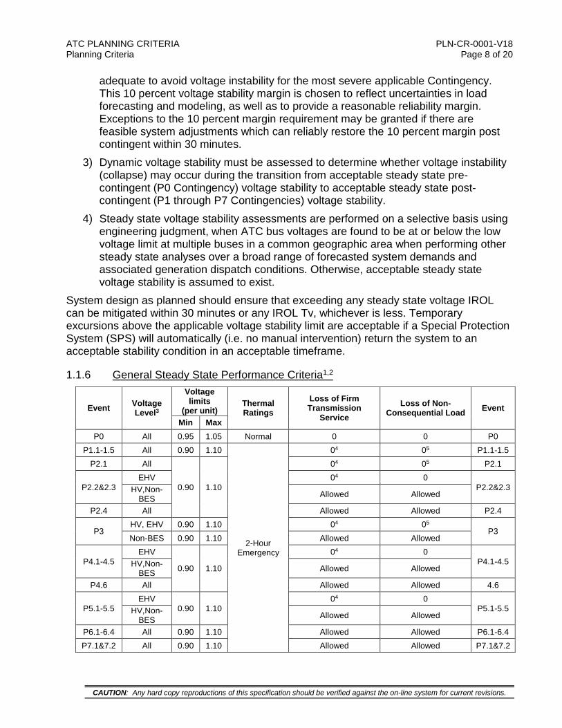
1.1.6 General Steady State Performance Criteria1,2
Event Voltage Level3
Voltage limits
(per unit) Thermal Ratings
Loss of Firm Transmission
Service Loss of Non-
Consequential Load Event
Min Max P0 All 0.95 1.05 Normal 0 0 P0
P1.1-1.5 All 0.90 1.10
2-Hour Emergency
04 05 P1.1-1.5 P2.1 All
0.90 1.10
04 05 P2.1
P2.2&2.3 EHV 04 0
P2.2&2.3 HV,Non-BES Allowed Allowed
P2.4 All Allowed Allowed P2.4
P3 HV, EHV 0.90 1.10 04 05
P3 Non-BES 0.90 1.10 Allowed Allowed
P4.1-4.5 EHV
0.90 1.10
04 0 P4.1-4.5 HV,Non-
BES Allowed Allowed
P4.6 All Allowed Allowed 4.6
P5.1-5.5 EHV
0.90 1.10 04 0
P5.1-5.5 HV,Non-BES Allowed Allowed
P6.1-6.4 All 0.90 1.10 Allowed Allowed P6.1-6.4 P7.1&7.2 All 0.90 1.10 Allowed Allowed P7.1&7.2
ATC PLANNING CRITERIA PLN-CR-0001-V18 Planning Criteria Page 9 of 20
CAUTION: Any hard copy reproductions of this specification should be verified against the on-line system for current revisions.
Table Notes:
1. Generator reactive capability is reduced to 90 percent of the reported capability. 2. Steady State voltage stability is 10 percent from the nose of the P-V curve. 3. ‘All’ is defined as ATC owned equipment at any voltage level. ‘EHV’ is defined as,
300-kV and above, ATC owned equipment at ‘HV’ is defined as ATC owned equipment strictly less than 300-kV and greater than or equal to 100-kV. ‘Non-BES’ is defined as ATC owned 69-kV through 99-kV equipment.
4. Footnote 9 in TPL-001-4 An objective of the planning process should be to minimize the likelihood and magnitude of interruption of Firm Transmission Service following Contingency events. Curtailment of Firm Transmission Service is allowed both as a System adjustment (as identified in the column entitled ‘Initial Condition’) and a corrective action when achieved through the appropriate re-dispatch of resources obligated to re-dispatch, where it can be demonstrated that Facilities, internal and external to the Transmission Planner’s planning region, remain within applicable Facility Ratings and the re-dispatch does not result in any Non-Consequential Load Loss. Where limited options for re-dispatch exist, sensitivities associated with the availability of those resources should be considered.
5. Footnote 12 in TPL-001-4 An objective of the planning process is to minimize the likelihood and magnitude of Non-Consequential Load Loss following planning events. In limited circumstances, Non-Consequential Load Loss may be needed throughout the planning horizon to ensure that BES performance requirements are met. However, when Non-Consequential Load Loss is utilized under footnote 12 within the Near-Term Transmission Planning Horizon to address BES performance requirements, such interruption is limited to circumstances where the Non-Consequential Load Loss meets the conditions shown in Attachment 1. In no case can the planned Non-Consequential Load Loss under footnote 12 exceed 75 MW for US registered entities. The amount of planned Non-Consequential Load Loss for a non-US Registered Entity should be implemented in a manner that is consistent with, or under the direction of, the applicable governmental authority or its agency in the non-US jurisdiction.
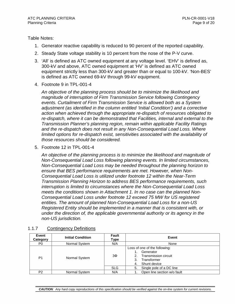
1.1.7 Contingency Definitions Event
Category Initial Condition Fault Type Event
P0 Normal System N/A None
P1 Normal System 3Φ
Loss of one of the following: 1. Generator 2. Transmission circuit 3. Transformer 4. Shunt device
SLG 5. Single pole of a DC line P2 Normal System N/A 1. Open line section w/o fault

ATC PLANNING CRITERIA PLN-CR-0001-V18 Planning Criteria Page 10 of 20
CAUTION: Any hard copy reproductions of this specification should be verified against the on-line system for current revisions.
SLG 2. Bus section fault 3. Internal non-bus-tie breaker fault 4. Internal bus-tie breaker fault
P3 Loss of generator unit followed by system adjustments
3Φ
Loss of one of the following: 1. Generator 2. Transmission circuit 3. Transformer 4. Shunt device
SLG 5. Single pole of a DC line
P4 Normal System SLG
Loss of multiple elements caused by a stuck breaker (non-bus-tie) attempting to clear a Fault on one of the following:
1. Generator 2. Transmission circuit 3. Transformer 4. Shunt device 5. Bus section 6. Loss of multiple elements caused by a stuck
breaker (bus-tie breaker) attempting to clear a fault on the associated bus
P5 Normal System SLG
Delayed Fault clearing due to the failure of a non-redundant relay protecting the Faulted element to operate as designed, for one of the following:
1. Generator 2. Transmission circuit 3. Transformer 4. Shunt device 5. Bus section
P6
Loss of one of the following followed by System adjustments.
1. Transmission circuit 2. Transformer 3. Shunt device 4. Single DC line pole
3Φ
Loss of one of the following: 1. Transmission circuit 2. Transformer 3. Shunt device
SLG 4. Single pole of a DC line
P7 Normal System SLG The loss of:
1. Any two adjacent circuit on a common tower 2. Loss of a bipolar DC line
1.2 Dynamic Stability Assessments Overview The dynamics cases are built to be consistent with the regional dynamics database except for the load modeling, which may consist of appropriate load and motor modeling for voltage stability assessments. Dynamic stability assessments will include consideration of the following system load conditions.
1) Summer peak 2) Light load
The dynamic load conditions have the following general applications. 1) Summer peak – This load condition is typically used for voltage stability studies to
determine whether system disturbances during peak load conditions cause voltage instability. Also, since the performance of wind generators is more closely linked to system voltage performance, summer peak cases should be considered when assessing the performance of wind generation.
ATC PLANNING CRITERIA PLN-CR-0001-V18 Planning Criteria Page 11 of 20
CAUTION: Any hard copy reproductions of this specification should be verified against the on-line system for current revisions.
2) Light load – This load condition is typically used for dynamic stability assessments in order to assess the angular stability of synchronous machines (e.g. fossil fuel generators). Empirically, it is noted that the dynamic performance of synchronous machines is worse in lighter load conditions likely due to lower field excitation current.
Transient and dynamic stability assessments of the planning horizon are generally performed by the System Planning Department to assure adequate avoidance of loss of generator synchronism, prevention of system voltage collapse, and system reactive power resources within 20 seconds after a system disturbance. The transient and dynamic system stability performance criteria to be utilized by ATC for planning purposes shall include the following factors. (Applicable NERC Standard: TPL-001-4, R2.4, R2.5, and R4)
1.2.1 Large Disturbance Stability Performance Assessment 1) For generator transient stability, faults will be modeled on the high side bus at
generating plants. 2) For generating units with actual “as built” or “field setting” dynamic data, a 0.5 cycle
margin will be added to the expected clearing time (ECT) for dynamic Contingency simulations. For generating units with assumed, typical, or proposed dynamic data, a 1.0 cycle margin will be added to the ECT for dynamic Contingency simulations. The total clearing time (ECT + margin) must be equal to or less than the calculated critical clearing time (CCT) from the simulation.
3) Generator transient stability will be demonstrated for at least one key Contingency for each applicable P1 through P7 Contingency. Unacceptable transient stability performance occurs when any of the stability assessment criteria are not met. A. Angular Stability Assessment
i. Generating unit loses synchronism with the transmission system, unless it is deliberately islanded
ii. Cascading tripping of transmission lines, tripping of transmission transformers or uncontrolled loss of load
iii. Poorly damped angular oscillations where acceptable damping is defined in Section 1.2.2 below
B. Voltage Stability Assessment i. Transient stability voltage response at applicable Bulk-Electric System (BES)
buses serving load shall recover to at least 80% of nominal voltage within 2 seconds of the initiating event for all P1-P7 Contingencies
ii. For voltage swings subsequent to fault clearing and the first voltage recovery above 80%, voltage dips at each applicable BES bus serving load shall not dip below 70% of nominal voltage for more than 30 cycles or remain below 80% of nominal voltage for more than 2 seconds for all P1-P7 Contingencies

ATC PLANNING CRITERIA PLN-CR-0001-V18 Planning Criteria Page 12 of 20
CAUTION: Any hard copy reproductions of this specification should be verified against the on-line system for current revisions.
4) Where needed system reinforcement cannot be implemented in an appropriate timeframe, then a corrective plan must be established in order to respect System Operating Limits and/or Interconnected Reliability Operating Limits. Where appropriate, corrective plans may include generator redispatch, operating guides, and/or Special Protection Systems.
1.2.2 Small Disturbance Performance Assessment Small disturbance (e.g. switching) stability performance criteria to be utilized by ATC will include the following characteristics.
1) Unacceptable small disturbance performance consists of a response beyond the limits described below. Unacceptable small disturbance performance indicates that a System Operating Limit (SOL) or an Interconnected Reliability Operating Limit (IROL) exists for the Planning Horizon where improvements cannot be implemented in an appropriate timeframe.
2) With all generating units at their prescribed base case (normally full) real power output, all units will exhibit well damped angular oscillations [as defined below] and acceptable power swings in response to a (non-fault) loss of a generator, transmission circuit, or transmission transformer.
3) With all generating units at their prescribed base case (normally maximum) real power output, all units will exhibit well damped angular oscillations [as defined below] and acceptable power swings in response to a (non-fault) loss of any two transmission circuits on a common structure.
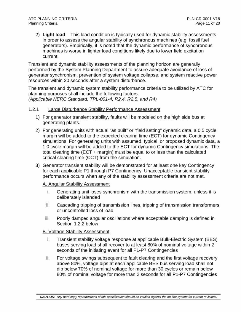
Well damped angular oscillations need to meet one of the following two criteria. 1) The generator rotor angle peak-to-peak magnitude is within 1.0 degree or less at 20
seconds after the switching event: 2) The generator average damping factor for the last five cycles of the 20 second
simulation is 15.0 percent or greater after the switching event.
Average Damping Factor (%) = 1004
4321 ×
+++ dddd
Where:
( )nn SPPRd −= 1 where SPPRn (Successive Positive Peak Ratio) is the ratio of the peak-to-peak amplitude of a rotor angle swing (nth cycle back from the 20 second simulation time) to the peak-to-peak amplitude of a rotor angle swing on the previous cycle (n+1th cycle back from the 20 second simulation time).
5
44 1
ppd −= ,
4
33 1
ppd −= ,
3
22 1
ppd −= ,
2
11 1
ppd −=
ATC PLANNING CRITERIA PLN-CR-0001-V18 Planning Criteria Page 13 of 20
CAUTION: Any hard copy reproductions of this specification should be verified against the on-line system for current revisions.
1.2.3 Extreme Disturbance Events (NERC Standard TPL-001-4 Table 1 Stability Extreme Events)
The NERC Stability Extreme Events that are expected to produce more severe system impacts should be evaluated to determine potential system impacts and vulnerabilities. If widespread Cascading may occur, then an evaluation of possible actions that would reduce the likelihood or mitigate the consequences of the extreme event should be performed.
1.3 Voltage Flicker The criteria for acceptable voltage flicker levels are defined by the requirements of regulatory entities in the states in which ATC owns and operates transmission facilities,
ATC PLANNING CRITERIA PLN-CR-0001-V18 Planning Criteria Page 14 of 20
CAUTION: Any hard copy reproductions of this specification should be verified against the on-line system for current revisions.
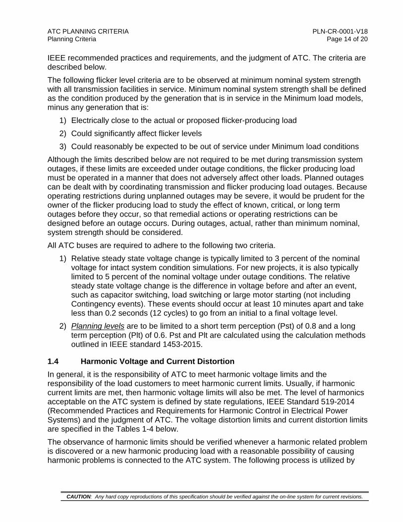
IEEE recommended practices and requirements, and the judgment of ATC. The criteria are described below. The following flicker level criteria are to be observed at minimum nominal system strength with all transmission facilities in service. Minimum nominal system strength shall be defined as the condition produced by the generation that is in service in the Minimum load models, minus any generation that is:
1) Electrically close to the actual or proposed flicker-producing load 2) Could significantly affect flicker levels 3) Could reasonably be expected to be out of service under Minimum load conditions
Although the limits described below are not required to be met during transmission system outages, if these limits are exceeded under outage conditions, the flicker producing load must be operated in a manner that does not adversely affect other loads. Planned outages can be dealt with by coordinating transmission and flicker producing load outages. Because operating restrictions during unplanned outages may be severe, it would be prudent for the owner of the flicker producing load to study the effect of known, critical, or long term outages before they occur, so that remedial actions or operating restrictions can be designed before an outage occurs. During outages, actual, rather than minimum nominal, system strength should be considered. All ATC buses are required to adhere to the following two criteria.
1) Relative steady state voltage change is typically limited to 3 percent of the nominal voltage for intact system condition simulations. For new projects, it is also typically limited to 5 percent of the nominal voltage under outage conditions. The relative steady state voltage change is the difference in voltage before and after an event, such as capacitor switching, load switching or large motor starting (not including Contingency events). These events should occur at least 10 minutes apart and take less than 0.2 seconds (12 cycles) to go from an initial to a final voltage level.
2) Planning levels are to be limited to a short term perception (Pst) of 0.8 and a long term perception (Plt) of 0.6. Pst and Plt are calculated using the calculation methods outlined in IEEE standard 1453-2015.
1.4 Harmonic Voltage and Current Distortion In general, it is the responsibility of ATC to meet harmonic voltage limits and the responsibility of the load customers to meet harmonic current limits. Usually, if harmonic current limits are met, then harmonic voltage limits will also be met. The level of harmonics acceptable on the ATC system is defined by state regulations, IEEE Standard 519-2014 (Recommended Practices and Requirements for Harmonic Control in Electrical Power Systems) and the judgment of ATC. The voltage distortion limits and current distortion limits are specified in the Tables 1-4 below. The observance of harmonic limits should be verified whenever a harmonic related problem is discovered or a new harmonic producing load with a reasonable possibility of causing harmonic problems is connected to the ATC system. The following process is utilized by

ATC PLANNING CRITERIA PLN-CR-0001-V18 Planning Criteria Page 15 of 20
CAUTION: Any hard copy reproductions of this specification should be verified against the on-line system for current revisions.
ATC when managing an existing harmonic-related problem or a new harmonic-producing load:
1) Existing problems – When a harmonic related problem is found on the ATC system, it is ATC’s responsibility to determine the source of the harmonics. If harmonic current limits are violated, the source of the harmonics will be required to decrease their harmonic currents to below the limits. If, after the harmonic current has been reduced to an acceptable level, the harmonic voltage is still causing a problem and above specified levels, it shall be the responsibility of ATC to bring the harmonic voltages within limits. If limits are not violated and there is still a harmonic related problem (an unlikely situation), it is the responsibility of the entity experiencing the problem to harden its equipment to the effect of harmonics or reduce the harmonics at their location. An existing violation of these harmonic limits that is not causing any problems does not necessarily require harmonic mitigation.
2) New harmonic producing loads – It is the responsibility of any customer wanting to connect a harmonic producing load to the ATC system to determine if the proposed load will violate the harmonic current limits and, if these limits are violated, to determine and implement steps necessary to reduce the harmonic currents to acceptable levels. If harmonic voltage limits are not met after harmonic current limits have been met, it is the responsibility of ATC to determine if the harmonic voltage distortion will cause any system problems and if they will, it is ATC’s responsibility to develop and implement a plan to meet the harmonic voltage limits.
Table 1 – IEEE 519 Voltage Distortion Limits Bus Voltage at Point of Common
Coupling Individual Voltage
Distortion (%) Total Voltage Distortion (%)
1-kV<V≤69-kV 3.0 5.0 69-kV<V≤161-kV 1.5 2.5
161-kV<V 1.0 1.5 Note 1: These limits should be used as system design values for the “worst case” for normal operation
(conditions lasting longer than one hour). For periods lasting less than one hour, these limits may be exceeded by 50 percent.
Note 2: High-voltage systems (>161-kV) can have up to two percent Total Voltage Distortion when caused by a HVDC terminal whose harmonics are attenuated by the time it is tapped by a user.
Table 2 – IEEE 519 Current Distortion Limits for General Systems with Nominal Voltages Between 120-V to 69-kV and All Power Generation Equipment Maximum Harmonic Current Distortion for Odd Harmonics
(Percent of IL) ISC/IL Individual Harmonic Order (%)
<11 11≤h<17 17≤h<23 23≤h<35 35≤h TDD <20 4.0 2.0 1.5 0.6 0.3 5.0
20<50 7.0 3.5 2.5 1.0 0.5 8.0 50<100 10.0 4.5 4.0 1.5 0.7 12.0
100<1000 12.0 5.5 5.0 2.0 1.0 15.0 >1000 15.0 7.0 6.0 2.5 1.4 20.0
ISC = maximum short circuit current at PCC IL = maximum demand load current (fundamental frequency component) at PCC Note 1: Even Harmonics are limited to 25 percent of the odd harmonic limits listed above. Note 2: Current distortions that result in a dc offset, e.g. half-wave converters, are not allowed. Note 3: All power generation equipment is limited to the ISC/IL<20 limits listed in this table, regardless of actual
ISC/IL.
ATC PLANNING CRITERIA PLN-CR-0001-V18 Planning Criteria Page 16 of 20
CAUTION: Any hard copy reproductions of this specification should be verified against the on-line system for current revisions.
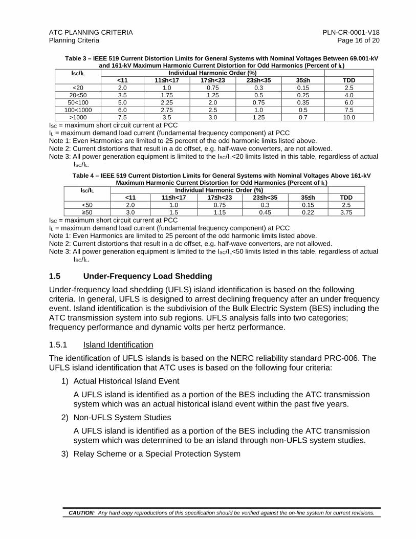
Table 3 – IEEE 519 Current Distortion Limits for General Systems with Nominal Voltages Between 69.001-kV and 161-kV Maximum Harmonic Current Distortion for Odd Harmonics (Percent of IL)
ISC/IL Individual Harmonic Order (%) <11 11≤h<17 17≤h<23 23≤h<35 35≤h TDD
<20 2.0 1.0 0.75 0.3 0.15 2.5 20<50 3.5 1.75 1.25 0.5 0.25 4.0 50<100 5.0 2.25 2.0 0.75 0.35 6.0
100<1000 6.0 2.75 2.5 1.0 0.5 7.5 >1000 7.5 3.5 3.0 1.25 0.7 10.0
ISC = maximum short circuit current at PCC IL = maximum demand load current (fundamental frequency component) at PCC Note 1: Even Harmonics are limited to 25 percent of the odd harmonic limits listed above. Note 2: Current distortions that result in a dc offset, e.g. half-wave converters, are not allowed. Note 3: All power generation equipment is limited to the ISC/IL<20 limits listed in this table, regardless of actual
ISC/IL. Table 4 – IEEE 519 Current Distortion Limits for General Systems with Nominal Voltages Above 161-kV
Maximum Harmonic Current Distortion for Odd Harmonics (Percent of IL) ISC/IL Individual Harmonic Order (%)
<11 11≤h<17 17≤h<23 23≤h<35 35≤h TDD <50 2.0 1.0 0.75 0.3 0.15 2.5 ≥50 3.0 1.5 1.15 0.45 0.22 3.75
ISC = maximum short circuit current at PCC IL = maximum demand load current (fundamental frequency component) at PCC Note 1: Even Harmonics are limited to 25 percent of the odd harmonic limits listed above. Note 2: Current distortions that result in a dc offset, e.g. half-wave converters, are not allowed. Note 3: All power generation equipment is limited to the ISC/IL<50 limits listed in this table, regardless of actual
ISC/IL.
1.5 Under-Frequency Load Shedding Under-frequency load shedding (UFLS) island identification is based on the following criteria. In general, UFLS is designed to arrest declining frequency after an under frequency event. Island identification is the subdivision of the Bulk Electric System (BES) including the ATC transmission system into sub regions. UFLS analysis falls into two categories; frequency performance and dynamic volts per hertz performance.
1.5.1 Island Identification The identification of UFLS islands is based on the NERC reliability standard PRC-006. The UFLS island identification that ATC uses is based on the following four criteria:
1) Actual Historical Island Event A UFLS island is identified as a portion of the BES including the ATC transmission system which was an actual historical island event within the past five years.
2) Non-UFLS System Studies A UFLS island is identified as a portion of the BES including the ATC transmission system which was determined to be an island through non-UFLS system studies.
3) Relay Scheme or a Special Protection System
ATC PLANNING CRITERIA PLN-CR-0001-V18 Planning Criteria Page 17 of 20
CAUTION: Any hard copy reproductions of this specification should be verified against the on-line system for current revisions.
A UFLS island is identified as a portion of the BES including the ATC transmission system which is planned to detach from the transmission system as a result of the operation of a relay scheme or a special protection system.
4) Large Single Island A UFLS island is identified as a single island in the MRO area, the RF area, or the Eastern Interconnection that includes the entire ATC transmission system. The island shall be selected by applying the above criteria and coordinating with the criteria of MISO and PJM to verify that all ATC UFLS schemes meet the PRC-006 standard performance requirements when acting together with or without the programs of the BES.
1.5.2 Frequency Performance Assessment Criteria Transient island frequencies shall remain within the Under-frequency and Over-frequency Performance Characteristic Curves in PRC-006 Standard Attachment 1.
1.5.3 Volts Per Hertz Assessment Criteria Transient Volts per Hertz values shall not exceed 1.18 per unit for longer than two seconds cumulatively per simulated event, and shall not exceed 1.10 per unit for longer than 45 seconds cumulatively per simulated event at each generator bus and generator step-up transformer high-side bus.

ATC PLANNING CRITERIA PLN-CR-0001-V18 Planning Criteria Page 18 of 20
CAUTION: Any hard copy reproductions of this specification should be verified against the on-line system for current revisions.
Figure 1 – Performance Characteristic Curves for UFLS Frequency Performance Criteria
2. VARIATIONS ON ATC PLANNING CRITERIA The ATC transmission system consists of assets contributed by entities within the five Balancing Authorities of the Wisconsin-Upper Michigan Systems. Each of the original asset owners planned their system to separate planning criteria, particularly in regard to transient and dynamic performance. Therefore, as ATC has implemented its own planning criteria, portions of the system may require upgrades to meet the more stringent ATC criteria.

ATC PLANNING CRITERIA PLN-CR-0001-V18 Planning Criteria Page 19 of 20
CAUTION: Any hard copy reproductions of this specification should be verified against the on-line system for current revisions.
This section of the ATC planning criteria describes the philosophy that will be followed for completing projects in a portion of the system identified as deficient with respect to the ATC planning criteria. Area does not meet the ATC planning criteria performance requirements.
1) Complete projects required for bringing the existing system up to the ATC planning criteria performance requirements with no intentional delay.
2) New generator interconnections are not permitted until the ATC planning criteria are met with the addition of the new generator, if the new generator interconnection aggravates the stability condition [A new generation interconnection is deemed to aggravate the stability performance of an area if a change in scope is required to meet the ATC planning criteria. See NERC Standard FAC-002-1 for new generator interconnections].
3) Depending on the level of risk associated with the deficiency, special operating procedures (restrictions or guides) may be required to mitigate the risk until the projects are completed. If a new generator interconnection is permitted but still negatively influences the stability condition, the operating restriction may follow a “last interconnected, first restricted” approach.
3. ADMINISTRATION
3.1 Review This document may be revised from time to time in response to changes in industry standards, new system conditions, new technologies and new operating procedures, as appropriate. Annually the need for a full review will be evaluated.
3.2 Retention The previous version of this document will be retained for at least five years after is becomes retired.
4. REVISION HISTORY
Revision Author(s) Manager(s) V.P.(s) Director(s)
Summary of Changes
14 Connie Lunde, et alia
David Smith, Paul Walter Ron Snead
Primary – split Criteria and Practices into separate documents, added voltage limit text, modified voltage stability margin text; Details – Summary of Planning Criteria V14 and Practices V1 Revisions document
15 Shane Ehster, et alia
David Smith, Paul Walter Ron Snead
Primary – Addition of UFLS criteria, added low voltage limit text for the P-V nose, revised Category D generator stability requirements, moved Variations on ATC Planning Criteria section from Assessment Practices document
16 Curtis Roe, et alia
David Smith, Paul Walter Ron Snead
Revised NERC references to TPL-001-4, revised annual review requirement, added criteria summary table, added maintenance plus in P1, and added TTL specifics
16.1 Curtis Roe, et alia
David Smith, Paul Walter Ron Snead Errata
ATC PLANNING CRITERIA PLN-CR-0001-V18 Planning Criteria Page 20 of 20
CAUTION: Any hard copy reproductions of this specification should be verified against the on-line system for current revisions.
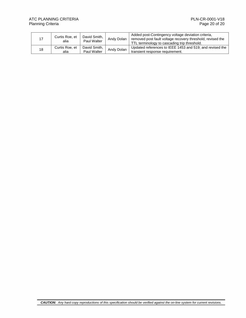
17 Curtis Roe, et alia
David Smith, Paul Walter Andy Dolan
Added post-Contingency voltage deviation criteria, removed post fault voltage recovery threshold, revised the TTL terminology to cascading trip threshold.
18 Curtis Roe, et alia
David Smith, Paul Walter Andy Dolan Updated references to IEEE 1453 and 519; and revised the
transient response requirement.