Embed Size (px)
Citation preview
FRONT END AND BACK END ANALOGSUBSYSTEMSEOVSA Technical Meeting, 6-9 November 2011W. Grammer, NRAO/NJIT

EOVSA Technical Meeting
2
Overview System-level diagram
Ambient-Temp Front End (2-meter antenna) Apex module Control cabinet
Cryogenic Front End (27-meter antenna)
Analog Back End Fiber RX and Block Downconverter LO generation and distribution Mechanical layout
OUTLINE
6-9 November 2011

EOVSA Technical Meeting
3
ANALOG SYSTEM OVERVIEW
6-9 November 2011

EOVSA Technical Meeting
4
GENERAL CHARACTERISTICS
13 x 2-m + 2 x 27-m antennas Ambient-temp. 2-m front end, Tsys < 400K Cooled 27-m front ends, Tsys ~ 50K (goal) Orthogonal linear polarization outputs
Tunable RF sky frequency range: 1 - 18 GHz
IF baseband output bandwidth: 500 MHz
Full RF BW analog transmission out of antennas, via SM optical fiber, ~ 1.2 km max.
6-9 November 2011

EOVSA Technical Meeting
5
FEED AND FRONT END
6-9 November 2011
Tecom 1-18 GHz Feed
EOVSA Technical Meeting
6
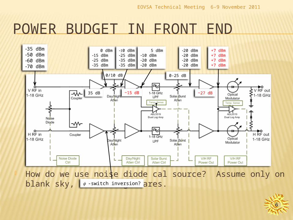
POWER BUDGET IN FRONT END
How do we use noise diode cal source? Assume only on blank sky, not during flares.
6-9 November 2011
-35 dBm-50 dBm-60 dBm-70 dBm
0 dBm-15 dBm-25 dBm-35 dBm
-10 dBm-25 dBm-35 dBm-35 dBm
5 dBm-10 dBm-20 dBm-20 dBm
-20 dBm-20 dBm-20 dBm-20 dBm
+7 dBm+7 dBm+7 dBm+7 dBm
35 dB ~15 dB
0/10 dB 0-25 dB
~27 dB
f -switch inversion?

EOVSA Technical Meeting
7
FRONT END COMPONENT SELECTION
System-level considerations Dynamic range High linearity
Requirement driven by RFI levels, detection limit Min. gain ripple/slope, any 500 MHz segment
Depends on quantization level in Correlator? Low gain and phase drift (small TC)
May require temp. control; one-sided (no TECs)? Reliability
Elevated temp. environment (> 40 ºC); lightning protection ?
6-9 November 2011
EOVSA Technical Meeting
8
FRONT END COMPONENT SELECTION
LNA For Tsys < 400K, NF ~ 2 dB may be OK, if feed loss <
1.5 dB across band Possible sources: Caltech, Microsemi, others ?
2nd/3rd Stage Amps Need additional gain to compensate for loss of added
output pads (for LF stability), and min. loss of filter, attenuators
Low Tc of gain desired – may require eval. testing Could use a VGA for 2nd or 3rd stage, if available Possible sources: PMI, Miteq, Microsemi, Hittite, Marki,
AMI
6-9 November 2011
EOVSA Technical Meeting
9
FRONT END COMPONENT SELECTION
Digital RF Attenuators Step resolution: 1 dB is sufficient Phase change w/atten. set is not an issue – calibrated out Possible sources: Narda, JFW, Herley, Hittite
Couplers/Splitters Possible sources: Narda, MCLI, M/A-Com?
1-18 GHz Lowpass Filter Rejects RF signals at 20-20.5 GHz from leaking through Possible sources: K&L
Noise Diode Possible sources: Noise-Com
6-9 November 2011

EOVSA Technical Meeting
10
FRONT END MODULE - MECHANICAL
Envelope is a 12” dia. cylinder (or ~ 8.5” x 8.5” rectangular box), TBD length
Weight limit is 20 lbs., pref. center of mass close to mounting plate
Component layout and packaging a challenge: Some components (e.g., couplers) are quite long Heat-generating components within a sealed
outdoor box make thermal management difficult Recommend thermal modeling – NRAO has
software (?)
6-9 November 2011
EOVSA Technical Meeting
11
PROBLEMATIC IN-BAND RFI AT SITE
Known strong fixed source at ~1.95 GHz May require a notch filter after LNA or 2nd stage
amplifier, with >20 dB rejection Passive notch filter properties
Need very high Q for a sharp, narrow-band response, combined with flat passband to 18 GHz.
May be difficult to design, as it also has to be compact Interference cancellation could be an elegant
alternative, but may add complexity and cost Need to research both, determine which is viable
6-9 November 2011

EOVSA Technical Meeting
12
ANTENNA CONTROL CABINET
Primarily for vendor-equipped motor controllers, power distribution for 2-m antenna
Space was provided for cRIO M&C unit, not much else Addition items for installation at each antenna:
Fiber breakout box, 6 conn. ports + 1 duplex cable Ethernet switch (1 x optical, ~4 x RJ-45) Optical demodulator for 1PPS timing signal Front End temperature control electronics Power supplies for Front End and all the above
May want a 2nd cabinet for above items. Can easily be located on same stand as existing box, or
back-to-back.
6-9 November 2011

EOVSA Technical Meeting
13
PHOTO OF ANTENNA CABINET
6-9 November 2011

EOVSA Technical Meeting
14
ANT. CABINET COMPONENT SELECTION Fiber breakout box
Details TBD Ethernet switch
Min. (4) Cat5 + full duplex SM opt., 10/100 Mbps 1310 nm wavelength chosen; use same at other
end Extended temp. range (-20 to 70°C); high MTBF Possible sources: Moxa, Phoenix Contact, Black
Box, TC Communications) Moxa unit is very competitively priced (~$400),
rugged, and has EMI and other certifications.
6-9 November 2011
EOVSA Technical Meeting
15
ANT. CABINET COMPONENT SELECTION Optical RX/Demodulator for 1PPS, timing
How are they generated optically? BPSK or AM-modulated RF subcarriers over fiber?
COTS product or custom design, depending on reqs. Should be fairly compact, low-power, robust Other requirements?
Front End temperature control Heat-only is simpler, more reliable, BUT only if OK to run at elev.
temps (~50-55°C).. Can use PWM AC – no DC supply. TEC requires hefty low-voltage DC supply, external heatsink,
fans. Reliability a concern. cRIO can be used for M&C, or separate COTS controller
(remoted) Mechanical thermal cutoff switch on heaters (Klixon), for safety
6-9 November 2011

EOVSA Technical Meeting
16
ANT. CABINET COMPONENT SELECTION Pointing telescope controller?
Is a temporary installation for a one-off measurement – do not need to support this
Power supplies Recommend linear supplies for Front End module
electronics, to avoid risk of spurious switching noise modulation on output signals
Switching supplies can be used for everything else
Recommend adding diagnostic M&C points for all supply outputs (voltage and currents)
6-9 November 2011

EOVSA Technical Meeting
17
ANALOG DOWNCONVERSION
6-9 November 2011

EOVSA Technical Meeting
18
POWER BUDGET IN BACK END
6-9 November 2011
-35 dBm-35dBm-35 dBm-35 dBm
-5 dBm-5 dBm-5 dBm-5 dBm
30 dB
-15 dBm-30 dBm
-5 dBm-15 dBm
-15 dBm-15 dBm
solar + band variation solar variation
-5 dBm-5 dBm

EOVSA Technical Meeting
19
BACK END COMPONENT SELECTION
Important considerations Good dynamic range High linearity (for in-band RFI) Minimal passband gain ripple Highly stable gain/phase with temperature High spurious and image rejection
6-9 November 2011

EOVSA Technical Meeting
20
BACK END COMPONENT SELECTION
Amplifiers Need somewhat more overall gain, to compensate for addl. fixed
pads on mixer and filter ports Low Tc of gain desired – may require eval. testing Could use VGA(s) w/integrated digital attenuator Possible sources:
(RF): PMI, Miteq, Microsemi, Hittite (IF): M/A-Com, Mini-Circuits, PMI, Hittite, Microsemi, RFMD, Analog Devices (LO): Hittite, Marki, Microsemi, PMI
May need isolator on LO amplifier inputs, to reduce LO output ripple Equalizer
Active “cable amp” with positive gain vs. freq. slope, compensates for negative slope from cables over ultra-wide 1-18 GHz band
Sources: PMI
6-9 November 2011

EOVSA Technical Meeting
21
BACK END COMPONENT SELECTION
Digital RF Attenuators Step resolution: 1 dB is sufficient Phase change w/atten. setting a concern? Possible sources: Narda, JFW, Herley, Hittite, Mini-Circuits
Mixers Ultra-wide bandwidths might require triple-balanced design, for
adequate higher-order rejection (TBC). Minor downside of this is higher LO power requirement Possible sources: Marki, Miteq, Hittite ?, M/A-Com ?
Microwave (1st IF) bandpass filter Small fractional bandwidth (~2.5%) makes it more difficult to get
sharp passband response. A cavity filter design might work well here. What level of LO and spurious rejection is required? Possible sources: K&L, Narda?, MCLI?
6-9 November 2011
EOVSA Technical Meeting
22
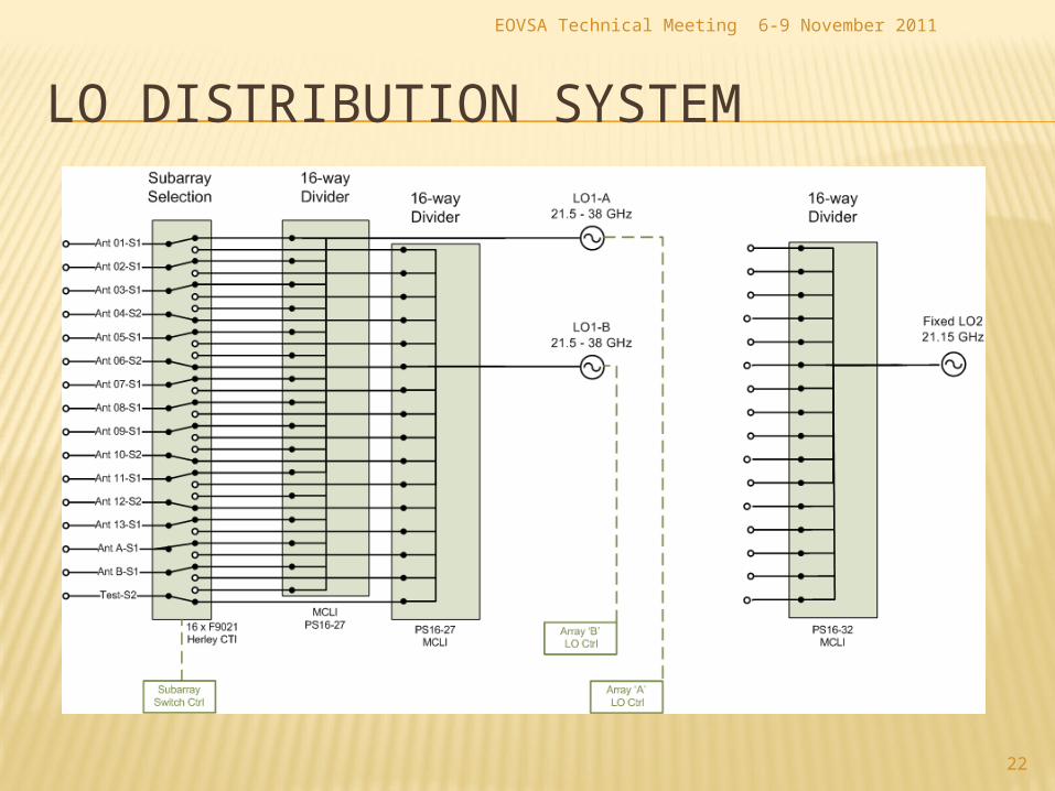
LO DISTRIBUTION SYSTEM
6-9 November 2011

EOVSA Technical Meeting
23
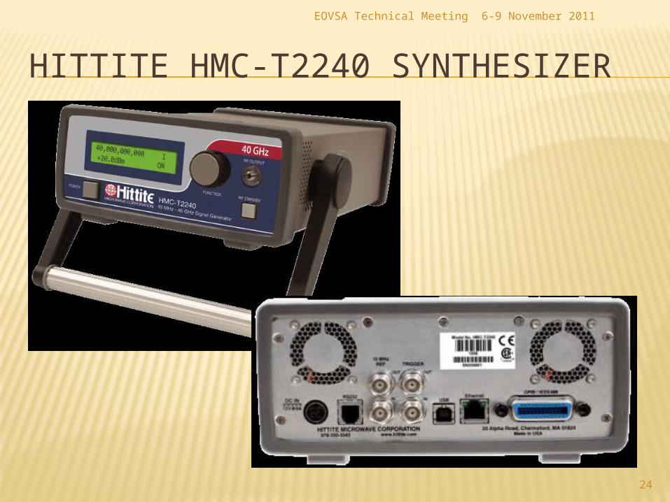
LO DISTRIBUTION COMPONENT SELECTION Hittite HMC-T2240 Synthesizer selected for LO1
Broad tuning range: 10 MHz – 40 GHz, 1 Hz resolution +20 dBm min. output over LO1 tuning range -52 dBc spurious subharmonics over LO1 tuning range,
+10 dBm output SSB phase noise (dBc/Hz @ f_offs), fo = 30 GHz:
-50 @ 10 Hz; -83 @ 1 kHz; -87 @ 100 kHz -106 @ 1 MHz; -128 @ 10 MHz; < -140 dBc/Hz n.f.
10 MHz int/ext ref.; < 1 ppm/yr. drift, 1.5 ppm acc. 500 us freq. sw. time; not freq-agile Manual or remote control via USB, GPIB or Ethernet Dual-unit rack mount kit available
6-9 November 2011
EOVSA Technical Meeting
24
HITTITE HMC-T2240 SYNTHESIZER
6-9 November 2011

EOVSA Technical Meeting
25
LO DISTRIBUTION COMPONENT SELECTION Fixed-tuned LO2 synthesizer (21.15 GHz)
Comparable phase noise, spurious specs to LO1 Assume +20 dBm minimum output (TBC) Internal ref. not needed – locked to LO1 10 MHz
reference output (+10 dBm available) Compact box module w/ext. DC supply
preferred, mounted close to 16-way splitter M&C functions: Lock and Alarm outputs, output
power monitor Possible sources: Miteq, Frequency Sources ?
6-9 November 2011

EOVSA Technical Meeting
26
LO DISTRIBUTION COMPONENT SELECTION 16-way Power Dividers
Possible sources: MCLI Coupled RF detector on one output, remotely monitored
Cabling 2.9mm coax required for single-mode operation to 40
GHz on LO1 lines. Higher unit loss than .141 semi-rigid SMA More costly
Recommend same for LO2 lines Length matching LO dist. cables on each subarray?
Greatly reduce differential phase drift over temperature Need to check cable properties to quantify this effect
6-9 November 2011

EOVSA Technical Meeting
27
LO DISTRIBUTION COMPONENT SELECTION Suggest a non-reflective SP2T switch, if available
Reflections from unterminated switch ports degrade isolation between the splitter ports
Will reduce power reflected back into LO source Consider using a mechanical coaxial switch
Much higher isolation, w/lower VSWR and insertion loss 100ms switching time, cycle life OK in this case (unless
we opt for “ping-pong” LO1 A-B switching, to get around limitations of Hittite LO1 source).
Single DC supply, low power (if latching) Possible candidate: Dow-Key 521Y series
6-9 November 2011

EOVSA Technical Meeting
28
BACK END POWER, M&C, PACKAGING
Recommend linear DC supplies for analog components in signal path, for same reasons as in Front End
Rack-level monitor and control unit will be cRIO Co-locate LO distribution network in the same
rack, close to Downconverter modules, to keep cable lengths as short as possible
Lay out modules for flow-through cooling? More constrained, but more uniform temperature distribution across modules.
6-9 November 2011

EOVSA Technical Meeting
29
GENERAL QUESTIONS & COMMENTS
Does construction budget include component spares? What level? (Ans: unknown)
What is the expected operational life of EOVSA? (Ans: assume 5 years, but could be longer)
Subsystem documentation standards? (Ans: None at the moment)
6-9 November 2011