Embed Size (px)
Citation preview
Classification: Internal
A Survey of North Sea EOR Projects Initiated During the Years 1975 to 2005A.R. Awan, SPE, NTNU/ Total E&P Norge; R. Teigland, SPE, Total E&P Norge; and J. Kleppe, SPE, NTNU
OG21 Seminar
15 Oct. 2008
2
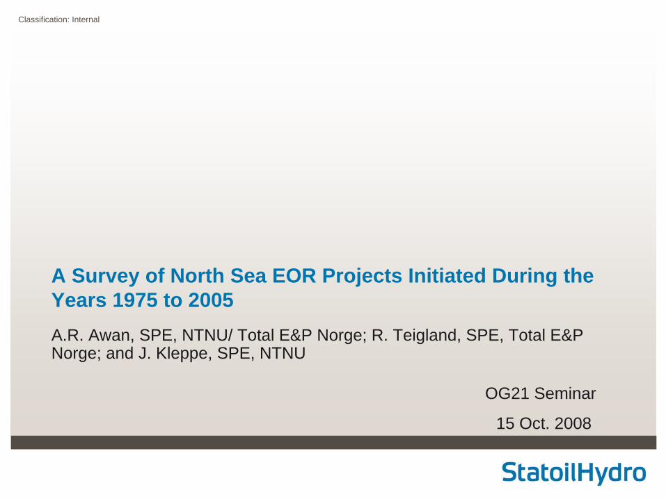
Introduction – Major IOR research programmes in the North Sea
1985
1980
1990
1995SPORSPOR
PROFITPROFIT
RUTHRUTH
Joint Joint Chalk Chalk
ResearchResearch
Recovery from Chalk reservoirs (Ongoing)
IOR / EOR methods
Reservoir characterization near well flowAdvanced IOR methods
3
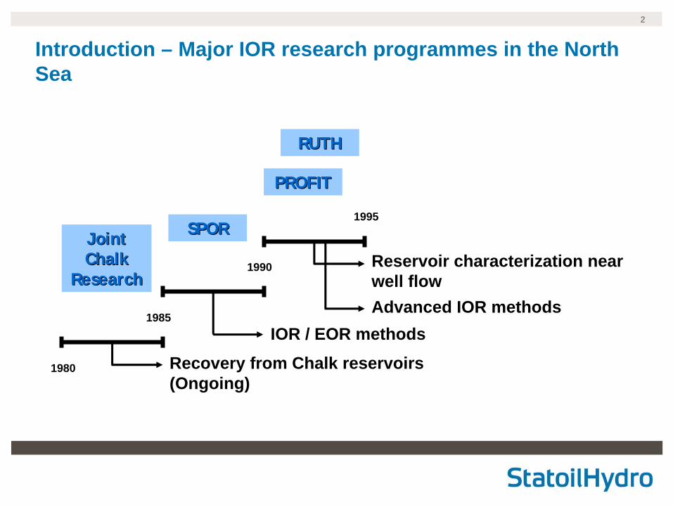
Introduction – EOR is important to achieve 50% recovery
30
35
40
45
50
1990 1995 2000 2005
Aver
age
reco
very
fact
or o
f oil
(%)• Current average recovery factors are above 40%
in the North Sea
• The estimated oil reserves on NCS in 2003 are about 3850 MSm³ (45% RF)
• However, 50% average oil recovery factor has been set as a target by NPD and OG21 (2005). This represents to 600 MSm³ (3776 Mbbls) additional oil
• EOR is one of the solutions to meet this goal
Avg. Oil Factor Evolution on the NCS-2005 (Source: NPD)
Goal: 50% RF
1 bbl = 0.1589 m3
M = million = 106
4
Objectives – Identify the EOR technologies initiated in the North Sea• What are the EOR technologies initiated in the North Sea?
• What are the leading companies and organizations involved in each of the EOR methods?
• Which one is the most successful EOR technology?
• Technology use restrictions?
• Maturity level and / or maturing timeframe?
• Future North Sea trend for EOR?
Laboratory techniques, world statistics, simulation tools and Laboratory techniques, world statistics, simulation tools and economical evaluation were not consideredeconomical evaluation were not considered
5
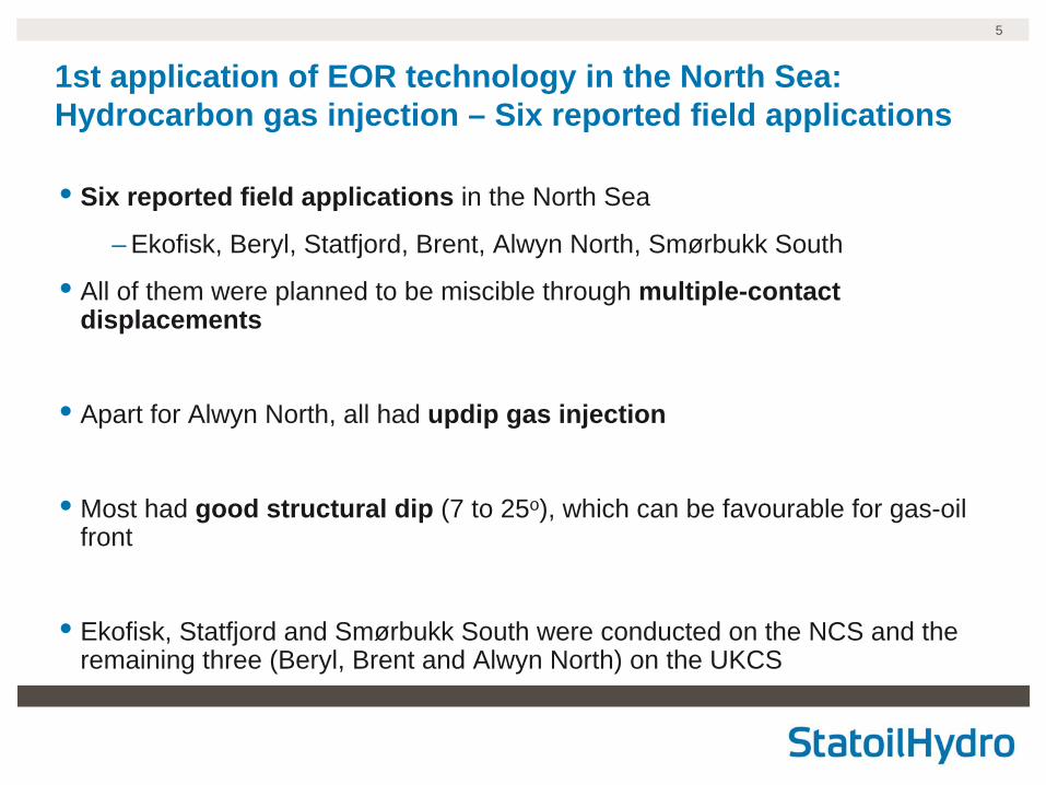
1st application of EOR technology in the North Sea: Hydrocarbon gas injection – Six reported field applications
• Six reported field applications in the North Sea
– Ekofisk, Beryl, Statfjord, Brent, Alwyn North, Smørbukk South
• All of them were planned to be miscible through multiple-contact displacements
• Apart for Alwyn North, all had updip gas injection
• Most had good structural dip (7 to 25o), which can be favourable for gas-oil front
• Ekofisk, Statfjord and Smørbukk South were conducted on the NCS and the remaining three (Beryl, Brent and Alwyn North) on the UKCS
6
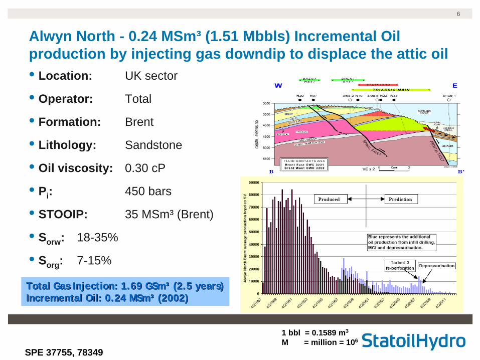
Alwyn North - 0.24 MSm³ (1.51 Mbbls) Incremental Oil production by injecting gas downdip to displace the attic oil• Location: UK sector
• Operator: Total
• Formation: Brent
• Lithology: Sandstone
• Oil viscosity: 0.30 cP
• Pi : 450 bars
• STOOIP: 35 MSm³ (Brent)
• Sorw : 18-35%
• Sorg : 7-15%
SPE 37755, 78349
Total Gas Injection: 1.69 GSmTotal Gas Injection: 1.69 GSm³³ (2.5 years)(2.5 years)Incremental Oil: 0.24 MSmIncremental Oil: 0.24 MSm³³ (2002)(2002)
1 bbl = 0.1589 m3
M = million = 106
7
Maturity level and / or maturing timeframe – Hydrocarbon Gas Injection is a mature technology
• The technology is mature worldwide
– Technical screening guidelines, field applications under secondary and tertiary conditions are well known
• In the North Sea, updip gas injection can work twofold - for gas storing / disposal as well as some incremental production (miscible displacement)
• Injection of other gases, especially CO2 is being considered

8
Technology use restrictions – North Sea reservoirs are very heterogeneous with high permeability streaks which lead to poor sweep efficiency
• Is gas and / or condensate sale more profitable than injecting?
• Thin formations are recommended unless dipping formations and high permeability streaks may be a killing factor
• APIo > 23, µo < 3, So > 30% PV, uniform permeability, high percentage of light components and depth above 1200m are recommended for miscible hydrocarbon gas process
9
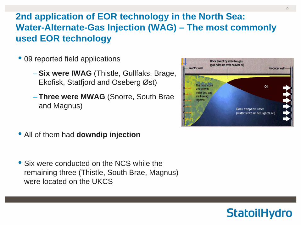
2nd application of EOR technology in the North Sea: Water-Alternate-Gas Injection (WAG) – The most commonly used EOR technology
• 09 reported field applications
– Six were IWAG (Thistle, Gullfaks, Brage, Ekofisk, Statfjord and Oseberg Øst)
– Three were MWAG (Snorre, South Brae and Magnus)
• All of them had downdip injection
• Six were conducted on the NCS while the remaining three (Thistle, South Brae, Magnus) were located on the UKCS
10
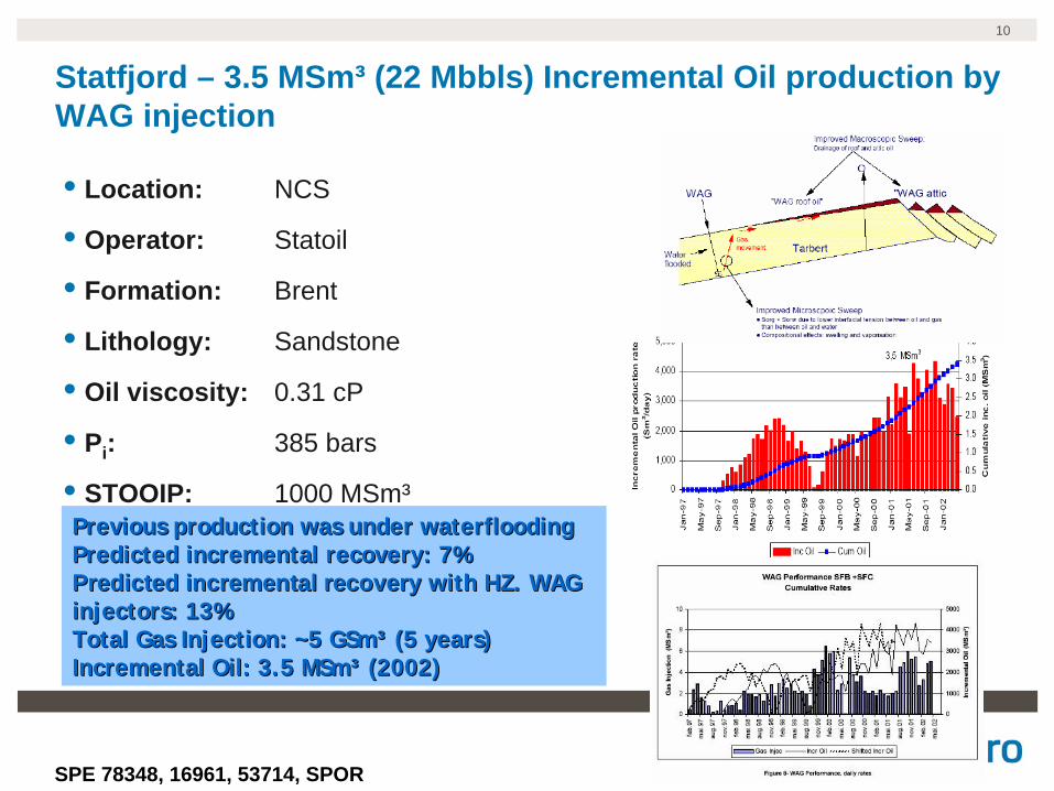
Statfjord – 3.5 MSm³ (22 Mbbls) Incremental Oil production by WAG injection
• Location: NCS
• Operator: Statoil
• Formation: Brent
• Lithology: Sandstone
• Oil viscosity: 0.31 cP
• Pi : 385 bars
• STOOIP: 1000 MSm³Previous production was under waterfloodingPrevious production was under waterfloodingPredicted incremental recovery: 7%Predicted incremental recovery: 7%Predicted incremental recoveryPredicted incremental recovery with HZ. WAG with HZ. WAG injectors: 13%injectors: 13%Total Gas Injection: ~5 GSmTotal Gas Injection: ~5 GSm³³ (5 years)(5 years)Incremental Oil: 3.5 MSmIncremental Oil: 3.5 MSm³³ (2002)(2002)
SPE 78348, 16961, 53714, SPOR
11
• The most commonly used EOR technology is WAG
• New relative permeability and capillary hysteresis models are required
• Availability of CO2 and technical issues of CO2 in the North Sea Chalk reservoirs need to be resolved
– CO2 MWAG at Gullfaks
• Better production profile than the current
– CO2 WAG at Ekofisk
• More incremental production than HC WAG
Maturity level and / or maturing timeframe – WAG is also a mature technology
12
Technology use restrictions
• Are gas sales more profitable than injecting?
• Increase in operational problems
– Hydrate formation can give injectivity problems (Ekofisk)
– Tubing annulus leaks, increase maintenance of gas compressor (Snorre)
– Heating and expansion of the tubing (Brage)
– Corrosion issues in case of CO2
• Pressure, temperature, composition of the injected gas and of the OOIP (MWAG)
• Well spacing, WAG ratio, reservoir thickness and permeability anisotropy
13
3rd application of EOR technology in the North Sea: Simultaneous Water-Gas Injection (SWAG) - Maturity level and / or maturing timeframe• Very few worldwide field applications of SWAG
• Only applied at the Siri field in the North Sea due to limited amount of gas and gas compressor restrictions
• WAG has been used extensively because injectivity is better when one phase is injected at a time
• In the North Sea, SWAG can be favourable if injected hydrocarbon gas is limited and not economical to export
• Future research trend is more on WAG than SWAG
14
Technology use restrictions
• Increased monitoring of the system because of its instability (segregation)
• Injectivity problems because water and gas presence in the wellbore
• Water-Gas ratio, well spacing, permeability distribution and flow barriers

154th application of EOR technology in the North Sea: Foam Assisted WAG (FAWAG) – reduces gas mobility in the high permeable zones and enables more gas to be stored in the reservoir• Initial WAG cycle is more efficient than the later
– Gullfaks, Statfjord, Snorre, Brage
• Early gas breakthrough in later gas injection cycles mainly because the path is already established during the first gas injection
• FAWAG increases the sweep efficiency of gas
– Foam plugs the selected layers or zones with foam while the reservoir remains under WAG
– Foam can be injected either by surfactant alternating gas (SAG) or co- injection
16
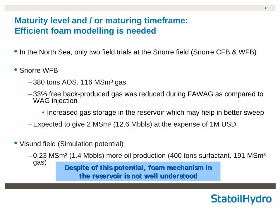
Maturity level and / or maturing timeframe: Efficient foam modelling is needed
• In the North Sea, only two field trials at the Snorre field (Snorre CFB & WFB)
• Snorre WFB
– 380 tons AOS, 116 MSm³ gas
– 33% free back-produced gas was reduced during FAWAG as compared to WAG injection
• Increased gas storage in the reservoir which may help in better sweep
– Expected to give 2 MSm³ (12.6 Mbbls) at the expense of 1M USD
• Visund field (Simulation potential)
– 0,23 MSm³ (1.4 Mbbls) more oil production (400 tons surfactant. 191 MSm³ gas)
Despite of this potential, foam mechanism in Despite of this potential, foam mechanism in the reservoir is not well understoodthe reservoir is not well understood
17
Technology use restrictions
• Gas injectivity below fracturing pressure (SAG is better than co-injection)
• Large inter-well distance (1000 – 2000m), vertical permeability and interlayer communication may limit foam propagation
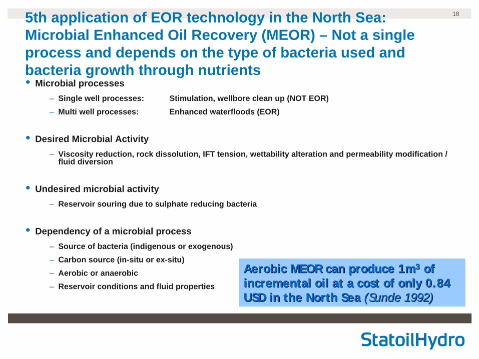
185th application of EOR technology in the North Sea: Microbial Enhanced Oil Recovery (MEOR) – Not a single process and depends on the type of bacteria used and bacteria growth through nutrients• Microbial processes
– Single well processes: Stimulation, wellbore clean up (NOT EOR)– Multi well processes: Enhanced waterfloods (EOR)
• Desired Microbial Activity– Viscosity reduction, rock dissolution, IFT tension, wettability alteration and permeability modification /
fluid diversion
• Undesired microbial activity– Reservoir souring due to sulphate reducing bacteria
• Dependency of a microbial process– Source of bacteria (indigenous or exogenous)– Carbon source (in-situ or ex-situ)– Aerobic or anaerobic– Reservoir conditions and fluid properties
Aerobic MEOR can produce 1mAerobic MEOR can produce 1m33 of of incremental oil at a cost of only 0.84 incremental oil at a cost of only 0.84 USD in the North Sea USD in the North Sea (Sunde 1992)(Sunde 1992)
19
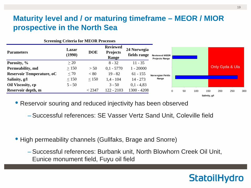
Maturity level and / or maturing timeframe – MEOR / MIOR prospective in the North Sea
Porosity, % > 20 8 - 32 11 - 35Permeability, md > 150 > 50 0,1 - 5770 1 - 20000Reservoir Temperature, oC < 70 < 80 19 - 82 61 - 155Salinity, g/l < 150 < 150 1,4 - 104 14 - 273Oil Viscosity, cp 5 - 50 3 - 50 0,1 - 4,83Reservoir depth, m < 2347 122 - 2103 1300 - 4208
Screening Criteria for MEOR Processes
ParametersReviewed Projects Range
24 Norwegian fields range
Lazar (1990) DOE
0 50 100 150 200 250 300Salinity, g/l
Norwegian FieldsRange
Reviewed MEORProjects Range
Only Gyda & Ula
• Reservoir souring and reduced injectivity has been observed
– Successful references: SE Vasser Vertz Sand Unit, Coleville field
• High permeability channels (Gullfaks, Brage and Snorre)
– Successful references: Burbank unit, North Blowhorn Creek Oil Unit, Eunice monument field, Fuyu oil field
20
Technology use restrictions
• Generally layer permeability greater than 50 md, reservoir temperature less than 80 oC, salinity less than 150 g/l and reservoir depth less than 2400 m are suitable for microbial growth
• Corrosion issues in case of aerobic process
• Logistic problems in case of anaerobic process (specific to North Sea)
21
1.01.0
1.01.0
3.0
1.0
2.0
5.0
1.01.0
19.0
1.0
1.0
GI 1975
GI 1977
GI 1979
WAG1980
GI 1981
WAG1991
WAG1994
WAG1996
WAG /FAWAG
1997
GI /WAG /
SWAG /
MEOR2001
WAG2002
Total
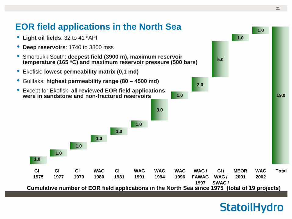
• Light oil fields: 32 to 41 oAPI
• Deep reservoirs: 1740 to 3800 mss
• Smorbukk South: deepest field (3900 m), maximum reservoir temperature (165 oC) and maximum reservoir pressure (500 bars)
• Ekofisk: lowest permeability matrix (0,1 md)• Gullfaks: highest permeability range (80 – 4500 md)• Except for Ekofisk, all reviewed EOR field applications
were in sandstone and non-fractured reservoirs
EOR field applications in the North Sea
Cumulative number of EOR field applications in the North Sea since 1975 (total of 19 projects)
22
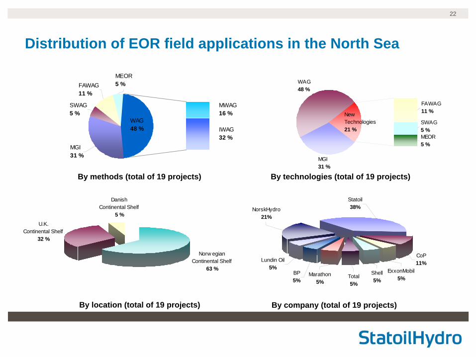
Distribution of EOR field applications in the North Sea
Norw egian Continental Shelf
63 %
U.K. Continental Shelf
32 %
Danish Continental Shelf
5 %
By methods (total of 19 projects) By technologies (total of 19 projects)
By company (total of 19 projects)By location (total of 19 projects)
WAG48 %
MEOR5 %
MGI31 %
MWAG16 %
IWAG32 %
FAWAG11 %
SWAG5 %
MEOR5 %
SWAG5 %
FAWAG11 %
WAG48 %
MGI31 %
New Technologies21 %
CoP11%
ExxonMobil5%
Shell5%
Total5%
Marathon5%
BP5%
Lundin Oil5%
NorskHydro21%
Statoil38%
23
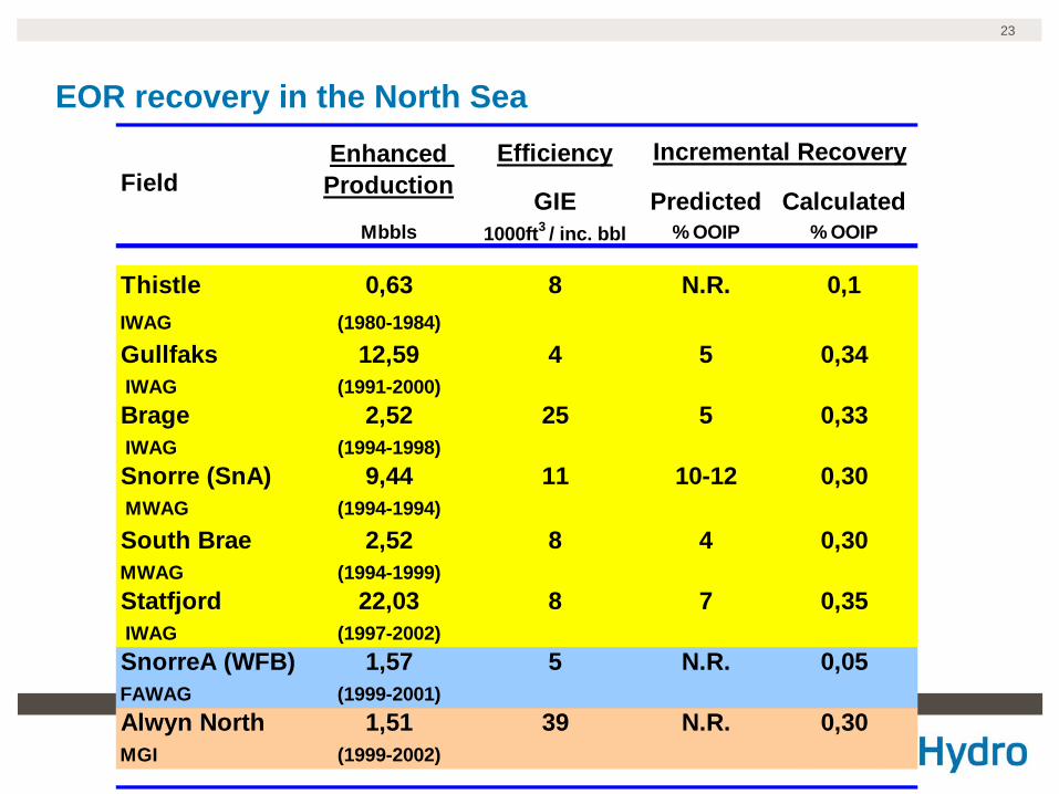
EOR recovery in the North SeaEfficiency
GIE Predicted CalculatedMbbls 1000ft3 / inc. bbl % OOIP % OOIP
Thistle 0,63 8 N.R. 0,1IWAG (1980-1984)
Gullfaks 12,59 4 5 0,34 IWAG (1991-2000)Brage 2,52 25 5 0,33 IWAG (1994-1998)Snorre (SnA) 9,44 11 10-12 0,30 MWAG (1994-1994)
South Brae 2,52 8 4 0,30MWAG (1994-1999)Statfjord 22,03 8 7 0,35 IWAG (1997-2002)SnorreA (WFB) 1,57 5 N.R. 0,05FAWAG (1999-2001)Alwyn North 1,51 39 N.R. 0,30MGI (1999-2002)
FieldEnhanced Production
Incremental Recovery
24
Summary – EOR Survey in the North Sea
1. The EOR technologies initiated in the North Sea area) HGI (6 miscible field applications)b) WAG injection (3 miscible and 6 immiscible field applications) c) SWAG injection (1 field application)d) FAWAG injection (2 field applications)e) MEOR (1 field application “No published data”)
3. WAG vs. SWAG• Difference – field operation strategies• WAG – a mature technology• Enough gas – “WAG”• Limited gas – “SWAG”
2. Most successful EOR Technology “WAG”• No of field applications & Enhanced Production• Attic oil recovery and reduce Sor• Increase the economic value of the project
25
4. FAWAG• SAG is better than co-injection• Large potential & future applications are expected
6. Main Problems experienced were• Injectivity• Injection system monitoring• Reservoir heterogeneities
5. MEOR• To reduce reservoir souring & reduced injectivity• To plug high permeability channels• Aerobic technology – an attractive approach in the North Sea
7. EOR leader in the North Sea by• Technology - WAG• Location - NCS (63% of all reported EOR projects)• Company - Statoil
8. Future research trend• Microbial processes & CO2 injection• WAG (including SWAG) injection schemes

26
AcknowledgementI would like to thank Total E&P Norge and Norwegian University of Science & Technology (NTNU) for the permission to publish this work and providing sufficient support
In addition special thanks to Total, NPD, CIPR, Rogaland Research, Sintef and StatoilHydro expertise for their useful comments and contributions
27
Backup

28
WAG – Key design parameters• WAG Injection pattern
– 5-spot pattern with close well spacing has been reported most successful in onshore fields
– Expensive to drill new wells in the North Sea and therefore the wells are more likely to be placed based on geological considerations and seldom use any fixed injection pattern
• WAG at the Statfjord field
– Horizontal WAG injectors were used because of better efficiency than vertical
– Production wells were sidetracked to prevent early water and / or gas B.T
• WAG Ratio
– 1:1 is the optimum WAG ratio (Gullfaks, Brage, Snorre)
29
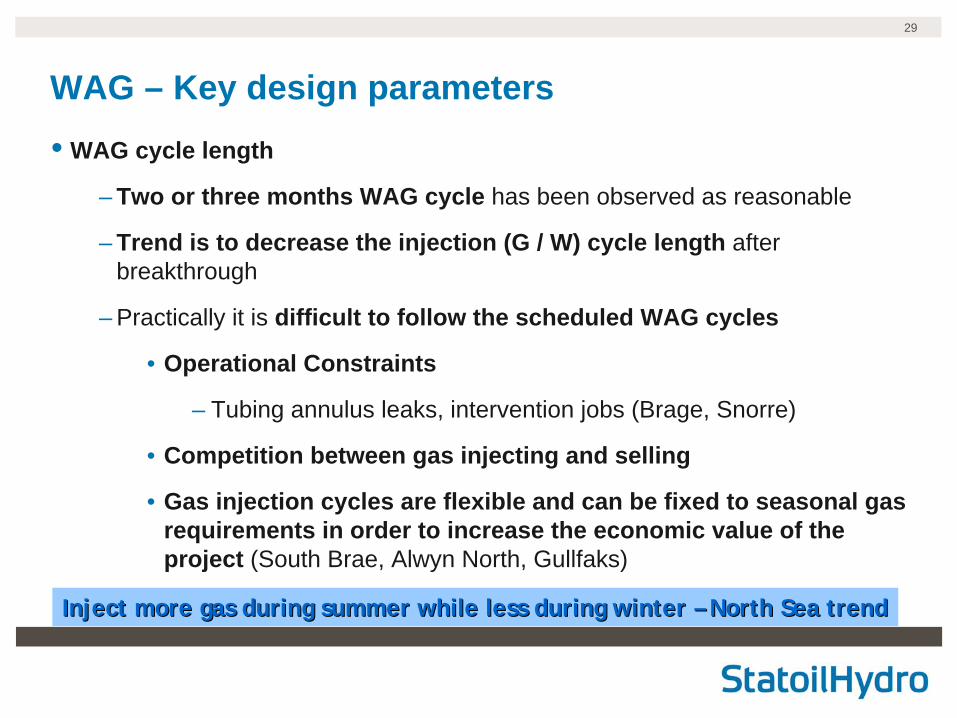
WAG – Key design parameters• WAG cycle length
– Two or three months WAG cycle has been observed as reasonable
– Trend is to decrease the injection (G / W) cycle length after breakthrough
– Practically it is difficult to follow the scheduled WAG cycles
• Operational Constraints
– Tubing annulus leaks, intervention jobs (Brage, Snorre)
• Competition between gas injecting and selling
• Gas injection cycles are flexible and can be fixed to seasonal gas requirements in order to increase the economic value of the project (South Brae, Alwyn North, Gullfaks)
Inject more gas during summer while less during winter Inject more gas during summer while less during winter –– North Sea trendNorth Sea trend
30
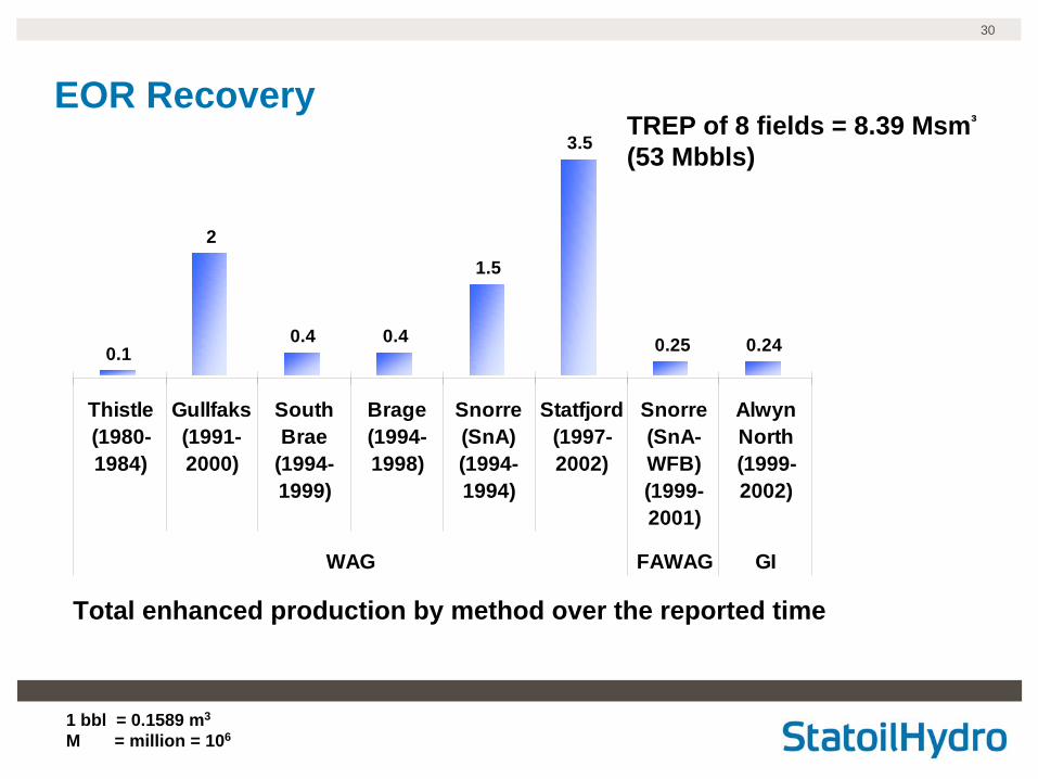
EOR Recovery
0.1
2
0.4 0.4
1.5
3.5
0.25 0.24
Thistle(1980-1984)
Gullfaks(1991-2000)
SouthBrae
(1994-1999)
Brage(1994-1998)
Snorre(SnA)(1994-1994)
Statfjord(1997-2002)
Snorre(SnA-WFB)(1999-2001)
AlwynNorth(1999-2002)
WAG FAWAG GI
Total enhanced production by method over the reported time
1 bbl = 0.1589 m3
M = million = 106
TREP of 8 fields = 8.39 Msm³
(53 Mbbls)
31
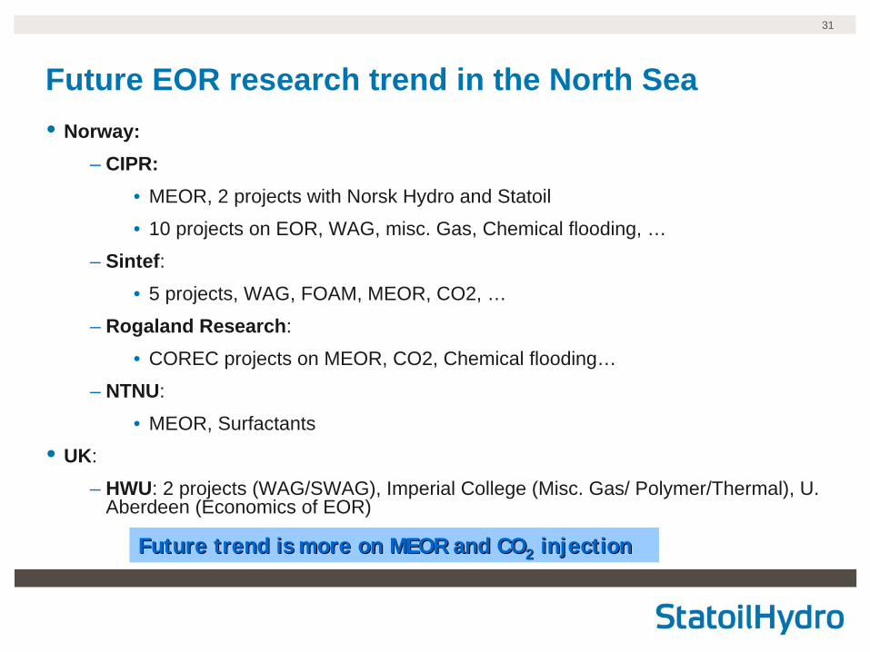
Future EOR research trend in the North Sea• Norway:
– CIPR:• MEOR, 2 projects with Norsk Hydro and Statoil
• 10 projects on EOR, WAG, misc. Gas, Chemical flooding, …
– Sintef:• 5 projects, WAG, FOAM, MEOR, CO2, …
– Rogaland Research:
• COREC projects on MEOR, CO2, Chemical flooding…
– NTNU:
• MEOR, Surfactants
• UK:
– HWU: 2 projects (WAG/SWAG), Imperial College (Misc. Gas/ Polymer/Thermal), U. Aberdeen (Economics of EOR)
Future trend is more on MEOR and COFuture trend is more on MEOR and CO 22 injectioninjection


![EOR - Enhanced Oil Recovery 01[1]](https://img.pdfslide.us/doc/110x75/577d2f9e1a28ab4e1eb22aa6/eor-enhanced-oil-recovery-011.jpg)