Embed Size (px)
Citation preview
GPON ONU Series
Eoptolink Technology Inc., Ltd. V1.h Page 1 of 11
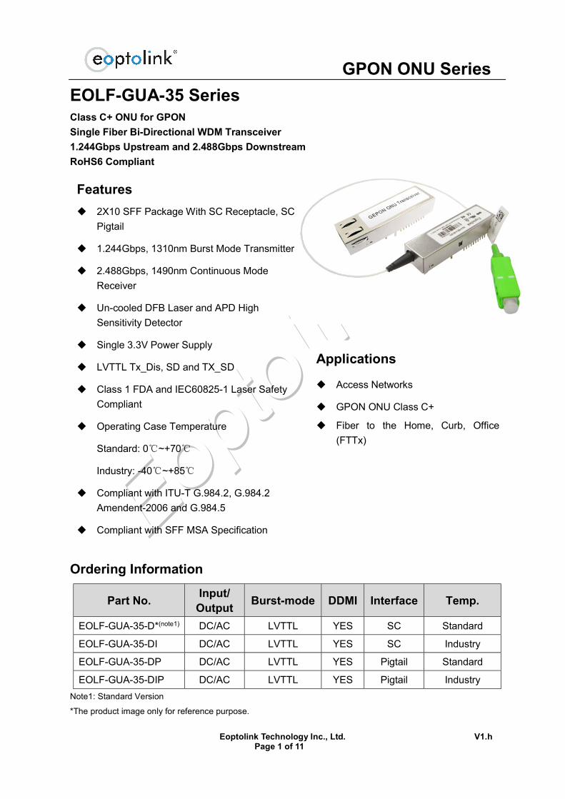
EOLF-GUA-35 Series Class C+ ONU for GPON
Single Fiber Bi-Directional WDM Transceiver
1.244Gbps Upstream and 2.488Gbps Downstream
RoHS6 Compliant
Ordering Information
Part No. Input/
Output Burst-mode DDMI Interface Temp.
EOLF-GUA-35-D*(note1) DC/AC LVTTL YES SC Standard
EOLF-GUA-35-DI DC/AC LVTTL YES SC Industry
EOLF-GUA-35-DP DC/AC LVTTL YES Pigtail Standard
EOLF-GUA-35-DIP DC/AC LVTTL YES Pigtail Industry
Note1: Standard Version
*The product image only for reference purpose.
Features
2X10 SFF Package With SC Receptacle, SC
Pigtail
1.244Gbps, 1310nm Burst Mode Transmitter
2.488Gbps, 1490nm Continuous Mode
Receiver
Un-cooled DFB Laser and APD High
Sensitivity Detector
Single 3.3V Power Supply
LVTTL Tx_Dis, SD and TX_SD
Class 1 FDA and IEC60825-1 Laser Safety
Compliant
Operating Case Temperature
Standard: 0℃~+70℃
Industry: -40℃~+85℃
Compliant with ITU-T G.984.2, G.984.2
Amendent-2006 and G.984.5
Compliant with SFF MSA Specification
Burst mode Tx DDMI function
Applications
Access Networks
GPON ONU Class C+
Fiber to the Home, Curb, Office
(FTTx)

GPON ONU Series
Eoptolink Technology Inc., Ltd. V1.h Page 2 of 11
Regulatory Compliance*Note2
Product Certificate Certificate Number Applicable Standard
TUV R50135086
EN 60950-1:2006+A11+A1+A12+A2
EN 60825-1:2014
EN 60825-2:2004+A1+A2
UL E317337 UL 60950-1
CSA C22.2 No. 60950-1-07
EMC CE AE 50285865 0001 EN 55022:2010
EN 55024:2010
FCC WTF14F0514417E 47 CFR PART 15 OCT., 2013
FDA / CDRH 1040.10
ROHS / 2011/65/EU Note2: The above certificate number updated to June 2014, because some certificate will be updated every year,
such as FDA and ROHS. For the latest certification information, please check with Eoptolink.
Functional Diagram
The Signal Detect (SD), Logic “1” represents the normal optical input level.
The following versions are available:
1. DC/AC Transceiver
Standard PECL inputs and CML outputs, TX is DC coupling and RX is AC coupling.
Product Description
Eoptolink’s high performance GPON ONU transceiver is designed for passive optical network
application. It can fully support the Class C+ ODN application specified by the ITU-T G.984.2
standard and ITU-T G.984.2 Amendent1.
The GPON ONU transceiver is packaged of small form factor 2x10 with a pigtail and SC connector.
The digital diagnostic monitoring function is compliant with SFF 8472 MSA.
The module consists of 1310nm un-cooled DFB Laser, InGaAs preamplifier and WDM filter in a
high-integrated optical sub-assembly. It transmits 1.244Gbps at 1310nm in burst mode and
receives 2.488Gbps at 1490nm in continuous mode.

GPON ONU Series
Eoptolink Technology Inc., Ltd. V1.h Page 3 of 11
Absolute Maximum Ratings*Note3
Parameter Symbol Min. Max. Unit Storage Temperature TS -40 +85 °C
Supply Voltage VCC -0.5 4.0 V
Operating Relative Humidity - 95 %
Wave Soldering Conditions Temp/Time - 260/10 °C/s
*Note3: Exceeding any one of these values may destroy the device immediately.
Recommended Operating Conditions
Parameter Symbol Min. Typical Max. Unit
Operating Case
Temperature Tc
EOLF-GUA-35-D 0 - 70 °C
EOLF-GUA-35-DI -40 - 85
Power Supply Voltage VCC 3.15 3.3 3.45 V
Power Supply Current ICC - - 300 mA
Date Rate Upstream/Downstream - 1.244/2.488 - Gbps
Performance Specifications - Electrical
Parameter Symbol Min. Typ. Max Unit Notes Transmitter
Tx DC Supply Current Icc - - 150 mA
LVPECL
Inputs(Differential) Vin 300 - 1900 mVpp
DC coupled
inputs
Input Impedance
(Differential) Zin 85 100 115 ohm
Rin > 100
kohm @ DC
Tx_Dis
Tx ON /
Enable VIH 2 - Vcc+0.3
V LVTTL, Control
Input Tx Off /
Disable VIL 0 - 0.8
Tx_SD
Laser
ON VOH 2 - Vcc+0.3
V
LVTTL, Output
high when Laser
is On Laser
OFF VOL 0 - 0.8
Receiver Rx Supply Current Icc - - 125 mA
CML Outputs
(Differential) Vout 600 - 1900 mVpp
AC coupled
outputs
Output Impedance
(Differential) Zout 85 100 115 ohm
RX_SD
SD 2 - Vcc+0.3 V Assert High
when signal is
detected LOSS 0 - 0.8 V

GPON ONU Series
Eoptolink Technology Inc., Ltd. V1.h Page 4 of 11
I2C Serial Logic
I2C Serial Data SDA_H 2 - Vcc+0.3 V
SDA_L 0 - 0.8 V
I2C Serial Clock SCL_H 2 - Vcc+0.3 V
SCL_L 0 - 0.8 V
Performance Specifications - Optical
Parameter Symbol Min. Typical Max. Unit Date Rate (Upstream/Downstream) R - 1.244/2488 - Gbps
Transmitter Centre Wavelength λC 1260 1310 1360 nm
-20dB Spectral Width Δλ - - 1 nm
Side Mode Suppression Ratio SMSR 30 - - dB
Average Output Power *(note4) Pout 0.5 - 5 dBm
Extinction Ratio*(note5) ER 10 - - dB
Rise/Fall Time (10%~90%) tR,tF - 0.15 0.26 ns
Output Optical Eye*(note6) ITU-T G984.2 Compliant
Optical Burst On/ Off Time t_on/t_off - - 12.8 ns
Additive Jitter Generation JA - - 0.2 UI
Optical Output Power with TX OFF*(note4) P_off - - -45 dBm
Transmitter and Dispersion Penalty TDP - - 0.5 dB
Transmit Reflectance RFL - - -30 dB
Optical Return Loss RL - - 15 dB
Receiver Centre Wavelength λc 1480 1490 1500 nm
Receiver Sensitivity*(note7) Pmin - - -30 dBm
Saturation Optical Power Pmax -8 - - dBm
Damage Threshold PDT - - 4 dBm
1555nm Rx to 1490nm Isolation - 30 - - dB
Receiver Reflectance Rf - - -20 dB
Polarization Dependent Loss PDL - - 0.5 dB
SD Assert SDA - - -31 dBm
SD De-Assert SDD -45 - - dBm
Signal Detect Hysteresis*(note8) 0.5 2 6 dBm
G.984.5 Wavelength Blocking Filter,
1530nm to1539nm WBF
7
dB G.984.5 Wavelength Blocking Filter,
1540nm to 1625nm 22
Note4: Measured with 9/125um G.652 SMF.
Note5: Filtered, measured with PRBS223-1 test pattern @1.244Gbps.
Note6: Eye Pattern Mask.

GPON ONU Series
Eoptolink Technology Inc., Ltd. V1.h Page 5 of 11
Note 7: Measured with a PRBS 223 -1 test pattern @2.488Gbps and ER=10dB, BER 1X10⁻⁴.
Note 8: LOS Hysteresis (SD signal coincides with the LOS signal inversion)
Transmitter Burst Mode Timing Characteristics
VccT Burst control Data Input Optical Output VccT < 2.5V X X OFF
VccT > 3.13V
Low X OFF
High/NC NO Other
Yes Laser bias and modulation signal output
“X” means don’t care.
“Other” means peak power less than +8dBm.
“High/Low” means Logic high/low level.
“No” means data not present, “Yes” means data present.
“OFF” means the optical power less than -45dBm.

GPON ONU Series
Eoptolink Technology Inc., Ltd. V1.h Page 6 of 11
Burst transmitter timing
Enhanced Digital Diagnostic Interface
The memory map in the following describes an extension to the memory map defined in SFF-8472
MSA. The enhanced interface uses the two wire serial bus address 1010001X (A2H) to provide
diagnostic information about the module’s present operating conditions.

GPON ONU Series
Eoptolink Technology Inc., Ltd. V1.h Page 7 of 11
SFF 2x10 Pin Function Definitions Tx/Rx Pin No. I/O Pin Name Description
Rx
1 NC No Function Definition
2 VeeR Receiver Ground
3 VeeR Receiver Ground
4 NC No Function Definition
5 NC No Function Definition
6 VeeR Receiver Ground
7 VccR +3.3V Receiver Power Supply
8 O SD Normal Optical Input indicated by logic “High”, and No
Optical Input indicated by logic “Low”.
9 O RD(n) Inverted Receiver Data Output (AC-Coupled internally)
10 O RD(p) Non-Inverted Receiver Data Output (AC-Coupled
internally)
Tx
11 VccT +3.3V Transmitter Power Supply
12 VeeT Transmitter Ground
13 I BiasCNT Default LVTTL Logic “High” to Enable Burst Transmitter,
and Disable Burst Transmitter by Logic “Low”.
14 I TD(p) Non-Inverted Transmitter Data Input (DC-Coupled)
15 I TD(n) Inverted Transmitter Data Input (DC-Coupled)
16 VeeT Transmitter Ground (Mod-Def 0)
17 I SCL I2C Serial Clock (LVTTL) (Mod-Def 1)
18 I/O SDA I2C Serial Data (LVTTL) (Mod-Def 2)
19 O TXF Indicate the TX fail.
20 O TX_SD Tx Transmitter State Indication, Assert high when
Transmitter ON. Or to the grand directly.
F Mounting Studs/Connect this pin to Chassis ground
The following figure illustrates the SFF 2x10 pin arrangement.
Pin arrangement (Top View)

GPON ONU Series
Eoptolink Technology Inc., Ltd. V1.h Page 8 of 11
Recommended Circuit Schematic
2x10

GPON ONU Series
Eoptolink Technology Inc., Ltd. V1.h Page 9 of 11
Mechanical Specifications
SC Receptacle
Pigtail with SC Connector
*This 2D drawing only for reference, please check with Eoptolink before ordering.

GPON ONU Series
Eoptolink Technology Inc., Ltd. V1.h Page 10 of 11
Laser Emission
Obtaining Document
You can visit our website:http://www.eoptolink.com Or contact Eoptolink Technology Inc., Ltd. listed at the end of the documentation to get the latest documents.
Revision History
Revision Initiated Reviewed Approved Description Release
Date V1.a Cathy Phlio Released. May 3, 2011
V1.b Phlio Kelly Update the
Transceiver Picture Aug. 18.2011
V1.c Phlio Kelly Add Nomenclature Aug. 22.2011
V1.d Phlio Kelly
Add class B+&C+,
PX20+ to
nomenclature.
Sep 2, 2011
V1.e Phlio Kelly Add G.984.5 and
isolation spec. Oct 24, 2011
V1.f Angela Kelly
Update SDD&ADD
&SD Hysteresis
and deleted
nomenclature
Nov 19,2012
V1.g Angela Kelly/Vina/Dean Phlio
Update the regulatory
compliance, note7 and
2D drawing.
Aug 22,2016
V1.h Angela Kelly/Vina/Dean/
Chao.Wang Phlio
Update the SDD/SDA,
product image and 2D
drawing.
July 24, 2017
Notice:
Eoptolink reserves the right to make changes to or discontinue any optical link product or service
identified in this publication, without notice, in order to improve design and/or performance.
Applications that are described herein for any of the optical link products are for illustrative
purposes only. Eoptolink makes no representation or warranty that such applications will be
suitable for the specified use without further testing or modification.
GPON ONU Series
Eoptolink Technology Inc., Ltd. V1.h Page 11 of 11
Contact:
Add: Floor 5, Building 2, No. 21 Gaopeng Avenue, High-Tech District, CHENGDU, SICHUAN
610041 P.R. CHINA
Tel: (+86) 028-85122709 ext 816 & 809
Fax: (+86) 028-85121912
Postal: 610041
E-mail:[email protected]
http://www.eoptolink.com