Embed Size (px)
Citation preview
E.O.D. ARMORY FLORIDA ARMY NATIONAL GUARD CAMP BLANDING JOINT TRAINING CENTER CONSTRUCTION AND FACILITY MANAGEMENT OFFICE STARKE, FLORIDA DEPARTMENT OF MILITARY AFFAIRS ARCHITECT’S PROJECT # 11070 CFMO PROJECT # 212011
DOOR HARDWARE – REVISED – 01-31-13 087100 - 1
SECTION 087100 - DOOR HARDWARE – REVISED 01-31-13
PART 1 - GENERAL
1.1 RELATED DOCUMENTS
A. Drawings and general provisions of the Contract, including General and Supplementary Conditions and Division 1 Specification Sections, apply to this Section.
1.2 SUMMARY
A. This Section includes the following:
1. Commercial door hardware for the following:
a. Swinging doors. b. Other doors to the extent indicated.
2. Cylinders for doors specified in other Sections.
B. Related Sections include the following:
1. Division 8 Section "Steel Doors and Frames" for astragals provided as part of a fire-rated labeled assembly and for door silencers provided as part of the frame.
C. Products furnished, but not installed, under this Section include the following. Coordinating, purchasing, delivering, and scheduling remain requirements of this Section.
1. Final replacement cores and keys to be installed by Owner.
1.3 SUBMITTALS
A. Product Data: Include installation details, material descriptions, dimensions of individual components and profiles, and finishes.
B. Shop Drawings.
C. Door Hardware Schedule: Prepared by or under the supervision of supplier, detailing fabrication and assembly of door hardware, as well as procedures and diagrams. Coordinate the final Door Hardware Schedule with doors, frames, and related work to ensure proper size, thickness, hand, function, and finish of door hardware.
1. Format: Comply with scheduling sequence and vertical format in DHI's "Sequence and Format for the Hardware Schedule."
E.O.D. ARMORY FLORIDA ARMY NATIONAL GUARD CAMP BLANDING JOINT TRAINING CENTER CONSTRUCTION AND FACILITY MANAGEMENT OFFICE STARKE, FLORIDA DEPARTMENT OF MILITARY AFFAIRS ARCHITECT’S PROJECT # 11070 CFMO PROJECT # 212011
DOOR HARDWARE – REVISED – 01-31-13 087100 - 2
2. Organization: Organize the Door Hardware Schedule into door hardware sets indicating complete designations of every item required for each door or opening.
a. Organize door hardware sets in same order as in the Door Hardware Schedule at the end of Part 3.
3. Content: Include the following information:
a. Type, style, function, size, label, hand, and finish of each door hardware item. b. Manufacturer of each item. c. Fastenings and other pertinent information. d. Location of each door hardware set, cross-referenced to Drawings, both on floor plans and
in door and frame schedule. e. Explanation of abbreviations, symbols, and codes contained in schedule. f. Mounting locations for door hardware. g. Door and frame sizes and materials. h. Description of each electrified door hardware function, including location, sequence of
operation, and interface with other building control systems.
1) Sequence of Operation: Include description of component functions that occur in the following situations: authorized person wants to enter; authorized person wants to exit; unauthorized person wants to enter; unauthorized person wants to exit.
4. Submittal Sequence: Submit the final Door Hardware Schedule at earliest possible date, particularly where approval of the Door Hardware Schedule must precede fabrication of other work that is critical in the Project construction schedule. Include Product Data, Samples, Shop Drawings of other work affected by door hardware, and other information essential to the coordinated review of the Door Hardware Schedule.
D. Keying Schedule: Prepared by or under the supervision of supplier, detailing Owner's final keying instructions for locks. Include schematic keying diagram and index each key set to unique door designations.
E. Warranties: Special warranties specified in this Section.
1.4 QUALITY ASSURANCE
A. Installer Qualifications: An experienced installer who has completed door hardware similar in material, design, and extent to that indicated for this Project and whose work has resulted in construction with a record of successful in-service performance.
B. Supplier Qualifications: Door hardware supplier with warehousing facilities in Project's vicinity and who is or employs a qualified Architectural Hardware Consultant, available during the course of the Work to consult with Contractor, Architect, and Owner about door hardware and keying.
1. Scheduling Responsibility: Preparation of door hardware and keying schedules.
E.O.D. ARMORY FLORIDA ARMY NATIONAL GUARD CAMP BLANDING JOINT TRAINING CENTER CONSTRUCTION AND FACILITY MANAGEMENT OFFICE STARKE, FLORIDA DEPARTMENT OF MILITARY AFFAIRS ARCHITECT’S PROJECT # 11070 CFMO PROJECT # 212011
DOOR HARDWARE – REVISED – 01-31-13 087100 - 3
C. Architectural Hardware Consultant Qualifications: A person who is currently certified by the Door and Hardware Institute as an Architectural Hardware Consultant and who is experienced in providing consulting services for door hardware installations that are comparable in material, design, and extent to that indicated for this Project.
D. Regulatory Requirements: Comply with provisions of the following:
1. Where indicated to comply with accessibility requirements, comply with Americans with Disabilities Act (ADA), "Accessibility Guidelines for Buildings and Facilities (ADAAG)," ANSI A117.1, as follows:
a. Handles, Pulls, Latches, Locks, and other Operating Devices: Shape that is easy to grasp with one hand and does not require tight grasping, tight pinching, or twisting of the wrist.
b. Door Closers: Comply with the following maximum opening-force requirements indicated:
1) Interior Hinged Doors: 5 lbf (22.2 N) applied perpendicular to door. 2) Sliding or Folding Doors: 5 lbf (22.2 N) applied parallel to door at latch. 3) Fire Doors: Minimum opening force allowable by authorities having jurisdiction.
c. Thresholds: Not more than 1/2 inch (13 mm) high. Bevel raised thresholds with a slope of not more than 1:2.
2. NFPA 101: Comply with the following for means of egress doors:
a. Latches, Locks, and Exit Devices: Not more than 15 lbf (67 N) to release the latch. Locks shall not require the use of a key, tool, or special knowledge for operation.
b. Delayed-Egress Locks: Lock releases within 15 seconds after applying a force not more than 15 lbf (67 N) for not more than 3 seconds.
c. Door Closers: Not more than 30 lbf (133 N) to set door in motion and not more than 15 lbf (67 N) to open door to minimum required width.
d. Thresholds: Not more than 1/2 inch (13 mm) high.
E. Fire-Rated Door Assemblies: Provide door hardware for assemblies complying with NFPA 80 that are listed and labeled by a testing and inspecting agency acceptable to authorities having jurisdiction, for fire ratings indicated, based on testing according to NFPA 252.
1. Test Pressure: Test at atmospheric pressure.
F. Keying Conference: Conduct conference at Project site with the Owner. Incorporate keying conference decisions into final keying schedule after reviewing door hardware keying system including, but not limited to, the following:
1. Function of building, flow of traffic, purpose of each area, degree of security required, and plans for future expansion.
2. Preliminary key system schematic diagram. 3. Requirements for key control system. 4. Address for delivery of keys.
G. Pre-installation Conference: Conduct conference at Project site. Review methods and procedures related to electrified door hardware including, but not limited to, the following:
E.O.D. ARMORY FLORIDA ARMY NATIONAL GUARD CAMP BLANDING JOINT TRAINING CENTER CONSTRUCTION AND FACILITY MANAGEMENT OFFICE STARKE, FLORIDA DEPARTMENT OF MILITARY AFFAIRS ARCHITECT’S PROJECT # 11070 CFMO PROJECT # 212011
DOOR HARDWARE – REVISED – 01-31-13 087100 - 4
1. Inspect and discuss preparatory work performed by other trades. 2. Review sequence of operation for each type of door hardware. 3. Review and finalize construction schedule and verify availability of materials, Installer's personnel,
equipment, and facilities needed to make progress and avoid delays. 4. Review required testing, inspecting, and certifying procedures. 5. Inspect frames for square conditions prior to door and hardware installation. Advise General
Contractor of frames needing correction prior to installation of doors.
1.5 DELIVERY, STORAGE, AND HANDLING
A. Inventory door hardware on receipt and provide secure lock-up for door hardware delivered to Project site.
B. Tag each item or package separately with identification related to the final Door Hardware Schedule, and include basic installation instructions with each item or package.
C. Deliver keys to Owner by registered mail or overnight package service.
1.6 COORDINATION
A. Coordinate layout and installation of recessed pivots and closers with floor construction. Cast anchoring inserts into concrete.
B. Templates: Obtain and distribute to the parties involved templates for doors, frames, and other work specified to be factory prepared for installing door hardware. Check Shop Drawings of other work to confirm that adequate provisions are made for locating and installing door hardware to comply with indicated requirements.
C. Electrical System Roughing-in: Coordinate layout and installation of door hardware with connections to power supplies, fire alarm system and detection devices, access control system, security system and building control system.
1.7 WARRANTY
A. General Warranty: Special warranties specified in this Article shall not deprive Owner of other rights Owner may have under other provisions of the Contract Documents and shall be in addition to, and run concurrent with, other warranties made by Contractor under requirements of the Contract Documents.
B. Warranty Period: One (1) year from date of Substantial Completion, unless otherwise indicated.
1.8 MAINTENANCE SERVICE
A. Maintenance Tools and Instructions: Furnish a complete set of specialized tools and maintenance instructions as needed for Owner's continued adjustment, maintenance, and removal and replacement of door hardware.
E.O.D. ARMORY FLORIDA ARMY NATIONAL GUARD CAMP BLANDING JOINT TRAINING CENTER CONSTRUCTION AND FACILITY MANAGEMENT OFFICE STARKE, FLORIDA DEPARTMENT OF MILITARY AFFAIRS ARCHITECT’S PROJECT # 11070 CFMO PROJECT # 212011
DOOR HARDWARE – REVISED – 01-31-13 087100 - 5
PART 2 - PRODUCTS
2.1 SCHEDULED DOOR HARDWARE
A. General: Provide door hardware for each door to comply with requirements in this Section, door hardware sets indicated in door and frame schedule, and the Door Hardware Schedule at the end of Part 3.
1. Door Hardware Sets: Requirements for quantity, item, design, grade, function, finish, size, and other distinctive qualities of each type of door hardware are indicated in the Door Hardware Schedule at the end of Part 3. Products are identified by descriptive titles corresponding to requirements specified in Part 2.
2.2 HINGES AND PIVOTS, GENERAL
A. Manufacturers: Subject to compliance with requirements, provide products by one of the following:
1. Hinges:
a. Hager Companies. b. Lawrence Brothers, Inc. c. McKinney Products Company; Div. of ESSEX Industries, Inc.
B. Standards: Comply with the following:
1. Butts and Hinges: BHMA A156.1. 2. Template Hinge Dimensions: BHMA A156.7. 3. Self-Closing Hinges and Pivots: BHMA A156.17. 4. Pivots: BHMA A156.4.
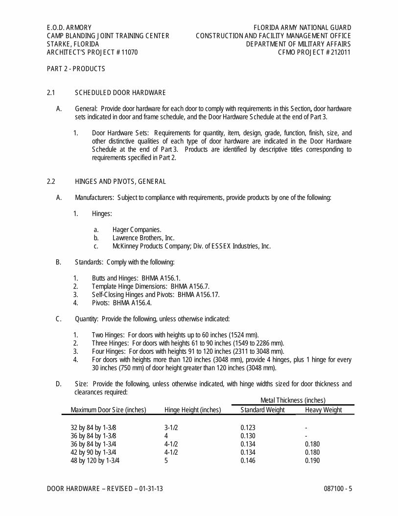
C. Quantity: Provide the following, unless otherwise indicated:
1. Two Hinges: For doors with heights up to 60 inches (1524 mm). 2. Three Hinges: For doors with heights 61 to 90 inches (1549 to 2286 mm). 3. Four Hinges: For doors with heights 91 to 120 inches (2311 to 3048 mm). 4. For doors with heights more than 120 inches (3048 mm), provide 4 hinges, plus 1 hinge for every
30 inches (750 mm) of door height greater than 120 inches (3048 mm).
D. Size: Provide the following, unless otherwise indicated, with hinge widths sized for door thickness and clearances required:
Metal Thickness (inches) Maximum Door Size (inches) Hinge Height (inches) Standard Weight Heavy Weight 32 by 84 by 1-3/8 3-1/2 0.123 - 36 by 84 by 1-3/8 4 0.130 - 36 by 84 by 1-3/4 4-1/2 0.134 0.180 42 by 90 by 1-3/4 4-1/2 0.134 0.180 48 by 120 by 1-3/4 5 0.146 0.190
E.O.D. ARMORY FLORIDA ARMY NATIONAL GUARD CAMP BLANDING JOINT TRAINING CENTER CONSTRUCTION AND FACILITY MANAGEMENT OFFICE STARKE, FLORIDA DEPARTMENT OF MILITARY AFFAIRS ARCHITECT’S PROJECT # 11070 CFMO PROJECT # 212011
DOOR HARDWARE – REVISED – 01-31-13 087100 - 6
E. Template Requirements: Except for hinges and pivots to be installed entirely (both leaves) into wood doors and frames, provide only template-produced units.
F. Hinge Applications: Unless otherwise indicated, provide the following:
1. Entrance Doors: Heavy-weight hinges. 2. Doors with Closers: Antifriction-bearing hinges. 3. Interior Doors: Standard-weight hinges.
G. Fasteners: Comply with the following:
1. Machine Screws: For metal doors and frames. Install into drilled and tapped holes. 2. Wood Screws: For wood doors and frames. 3. Threaded-to-the-Head Wood Screws: For fire-rated wood doors. 4. Screws: Use only manufacturer supplied fasteners with matching finish heads.
2.3 LOCKS AND LATCHES, GENERAL
A. Manufacturers: Subject to compliance with requirements, provide products by one of the following:
1. Mechanical Locks and Latches:
a. Best Lock Corporation
2. Bored Locks and Latches: BHMA A156.2. 3. Mortise Locks and Latches: BHMA A156.13. 4. Exit Locks: BHMA A156.5.
B. Bored Locks: BHMA Grade 1; Series 4000.
C. Certified Products: Provide door hardware listed in the following BHMA directories:
1. Mechanical Locks and Latches: BHMA's "Directory of Certified Locks & Latches."
D. Lock Throw: Comply with testing requirements for length of bolts to comply with labeled fire door requirements, and as follows:
1. Bored Locks: Minimum 1/2-inch (12.7-mm) latchbolt throw. 2. Mortise Locks: Minimum 3/4-inch (19-mm) latchbolt throw. 3. Deadbolts: Minimum 1-inch (25-mm) bolt throw.
2.4 DOOR BOLTS, GENERAL
A. Manufacturers: Subject to compliance with requirements, provide products by one of the following:
1. Surface Bolts:
a. Hager Companies.
E.O.D. ARMORY FLORIDA ARMY NATIONAL GUARD CAMP BLANDING JOINT TRAINING CENTER CONSTRUCTION AND FACILITY MANAGEMENT OFFICE STARKE, FLORIDA DEPARTMENT OF MILITARY AFFAIRS ARCHITECT’S PROJECT # 11070 CFMO PROJECT # 212011
DOOR HARDWARE – REVISED – 01-31-13 087100 - 7
b. Ives: H. B. Ives. c. Rockwood Manufacturing Company.
2. Flush Bolts:
a. Hiawatha, Inc. b. Ives: H. B. Ives. c. Rixson-Firemark, Inc.; Div. of Yale Security Inc. d. Rockwood Manufacturing Company.
B. Standards: Comply with the following:
1. Surface Bolts: BHMA A156.16. 2. Automatic and Self-Latching Flush Bolts: BHMA A156.3. 3. Manual Flush Bolts: BHMA A156.16.
2.5 EXIT DEVICES, GENERAL
A. Manufacturers: Subject to compliance with requirements, provide products by one of the following:
1. Corbin Russwin Architectural Hardware; Div. of Yale Security Inc. 2. Falcon / Ingersoll Rand Security Technologies. 3. Sargent Manufacturing Company; Div. of ESSEX Industries, Inc. 4. Yale Security Inc.; Div. of Williams Holdings.
B. Standard: BHMA A156.3.
1. BHMA Grade: Grade 1.
C. Certified Products: Provide exit devices listed in BHMA's "Directory of Certified Exit Devices."
D. Panic Exit Devices: Listed and labeled by a testing and inspecting agency acceptable to authorities having jurisdiction, for panic protection, based on testing according to UL 305.
E. Fire Exit Devices: Complying with NFPA 80 that are listed and labeled by a testing and inspecting agency acceptable to authorities having jurisdiction, for fire and panic protection, based on testing according to UL 305 and NFPA 252.
F. Through Bolts: For exit devices and trim on metal doors and fire-rated wood doors unless fire door blocking is specified in section 08211 Flush Wood Doors.
2.6 CYLINDERS AND KEYING
A. Manufacturers: Subject to compliance with requirements, provide products by one of the following:
1. Cylinders: Same manufacturer as for locks and latches. 2. Cylinders:
E.O.D. ARMORY FLORIDA ARMY NATIONAL GUARD CAMP BLANDING JOINT TRAINING CENTER CONSTRUCTION AND FACILITY MANAGEMENT OFFICE STARKE, FLORIDA DEPARTMENT OF MILITARY AFFAIRS ARCHITECT’S PROJECT # 11070 CFMO PROJECT # 212011
DOOR HARDWARE – REVISED – 01-31-13 087100 - 8
a. Best Locks Corporation.
3. Key Control Systems:
a. Key Control Systems, Inc. b. Major Metalfab Co. c. Sargent Manufacturing Company; Div. of ESSEX Industries, Inc.
B. Standards: Comply with the following:
1. Cylinders: BHMA A156.5. 2. Key Control System: BHMA A156.5.
C. Cylinder Grade: BHMA Grade 1.
D. Cylinders: Manufacturer's standard tumbler type, constructed from brass or bronze, stainless steel, or nickel silver, and complying with the following:
1. Number of Pins: Seven. 2. Mortise Type: Threaded cylinders with rings and straight- or clover-type cam. 3. Rim Type: Cylinders with back plate, flat-type vertical or horizontal tailpiece, and raised trim ring. 4. Bored-Lock Type: Cylinders with tailpieces to suit locks.
E. Construction Keying: Comply with the following:
1. Construction Master Keys: Provide cylinders with feature that permits voiding of construction keys without cylinder removal. Provide 10 construction master keys.
F. Keying System: Unless otherwise indicated, provide a factory-registered keying system complying with the following requirements:
1. Grand Master Key System: Cylinders are operated by a change key, a master key, and a grand master key.
a. Cylinders shall be master keyed at the direction of the designated owner’s representative. b. Keys: Provide nickel-silver keys complying with the following:
2. Stamping: Permanently inscribe each key with a visual key control number and include the following notation:
a. Notation: "DO NOT DUPLICATE."
3. Quantity: In addition to one extra blank key for each lock, provide the following:
a. Cylinder Change Keys: Three. b. Master Keys: Five. c. Grand Master Keys: Five.
E.O.D. ARMORY FLORIDA ARMY NATIONAL GUARD CAMP BLANDING JOINT TRAINING CENTER CONSTRUCTION AND FACILITY MANAGEMENT OFFICE STARKE, FLORIDA DEPARTMENT OF MILITARY AFFAIRS ARCHITECT’S PROJECT # 11070 CFMO PROJECT # 212011
DOOR HARDWARE – REVISED – 01-31-13 087100 - 9
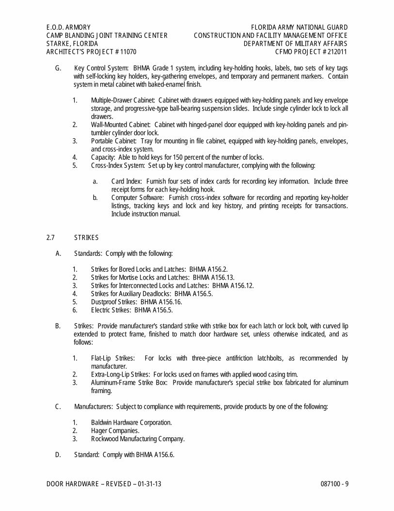
G. Key Control System: BHMA Grade 1 system, including key-holding hooks, labels, two sets of key tags with self-locking key holders, key-gathering envelopes, and temporary and permanent markers. Contain system in metal cabinet with baked-enamel finish.
1. Multiple-Drawer Cabinet: Cabinet with drawers equipped with key-holding panels and key envelope storage, and progressive-type ball-bearing suspension slides. Include single cylinder lock to lock all drawers.
2. Wall-Mounted Cabinet: Cabinet with hinged-panel door equipped with key-holding panels and pin-tumbler cylinder door lock.
3. Portable Cabinet: Tray for mounting in file cabinet, equipped with key-holding panels, envelopes, and cross-index system.
4. Capacity: Able to hold keys for 150 percent of the number of locks. 5. Cross-Index System: Set up by key control manufacturer, complying with the following:
a. Card Index: Furnish four sets of index cards for recording key information. Include three receipt forms for each key-holding hook.
b. Computer Software: Furnish cross-index software for recording and reporting key-holder listings, tracking keys and lock and key history, and printing receipts for transactions. Include instruction manual.
2.7 STRIKES
A. Standards: Comply with the following:
1. Strikes for Bored Locks and Latches: BHMA A156.2. 2. Strikes for Mortise Locks and Latches: BHMA A156.13. 3. Strikes for Interconnected Locks and Latches: BHMA A156.12. 4. Strikes for Auxiliary Deadlocks: BHMA A156.5. 5. Dustproof Strikes: BHMA A156.16. 6. Electric Strikes: BHMA A156.5.
B. Strikes: Provide manufacturer's standard strike with strike box for each latch or lock bolt, with curved lip extended to protect frame, finished to match door hardware set, unless otherwise indicated, and as follows:
1. Flat-Lip Strikes: For locks with three-piece antifriction latchbolts, as recommended by manufacturer.
2. Extra-Long-Lip Strikes: For locks used on frames with applied wood casing trim. 3. Aluminum-Frame Strike Box: Provide manufacturer's special strike box fabricated for aluminum
framing.
C. Manufacturers: Subject to compliance with requirements, provide products by one of the following:
1. Baldwin Hardware Corporation. 2. Hager Companies. 3. Rockwood Manufacturing Company.
D. Standard: Comply with BHMA A156.6.
E.O.D. ARMORY FLORIDA ARMY NATIONAL GUARD CAMP BLANDING JOINT TRAINING CENTER CONSTRUCTION AND FACILITY MANAGEMENT OFFICE STARKE, FLORIDA DEPARTMENT OF MILITARY AFFAIRS ARCHITECT’S PROJECT # 11070 CFMO PROJECT # 212011
DOOR HARDWARE – REVISED – 01-31-13 087100 - 10
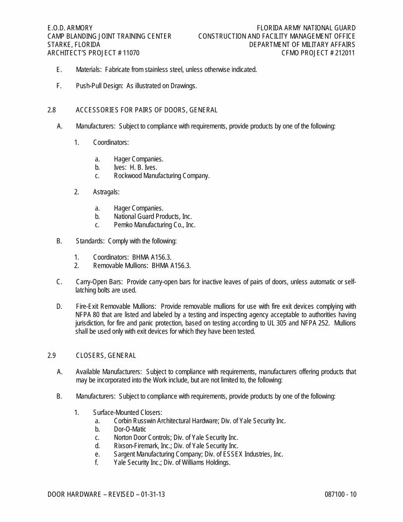
E. Materials: Fabricate from stainless steel, unless otherwise indicated.
F. Push-Pull Design: As illustrated on Drawings.
2.8 ACCESSORIES FOR PAIRS OF DOORS, GENERAL
A. Manufacturers: Subject to compliance with requirements, provide products by one of the following:
1. Coordinators: a. Hager Companies. b. Ives: H. B. Ives. c. Rockwood Manufacturing Company.
2. Astragals:
a. Hager Companies. b. National Guard Products, Inc. c. Pemko Manufacturing Co., Inc.
B. Standards: Comply with the following:
1. Coordinators: BHMA A156.3. 2. Removable Mullions: BHMA A156.3.
C. Carry-Open Bars: Provide carry-open bars for inactive leaves of pairs of doors, unless automatic or self-latching bolts are used.
D. Fire-Exit Removable Mullions: Provide removable mullions for use with fire exit devices complying with NFPA 80 that are listed and labeled by a testing and inspecting agency acceptable to authorities having jurisdiction, for fire and panic protection, based on testing according to UL 305 and NFPA 252. Mullions shall be used only with exit devices for which they have been tested.
2.9 CLOSERS, GENERAL
A. Available Manufacturers: Subject to compliance with requirements, manufacturers offering products that may be incorporated into the Work include, but are not limited to, the following:
B. Manufacturers: Subject to compliance with requirements, provide products by one of the following:
1. Surface-Mounted Closers: a. Corbin Russwin Architectural Hardware; Div. of Yale Security Inc. b. Dor-O-Matic c. Norton Door Controls; Div. of Yale Security Inc. d. Rixson-Firemark, Inc.; Div. of Yale Security Inc. e. Sargent Manufacturing Company; Div. of ESSEX Industries, Inc. f. Yale Security Inc.; Div. of Williams Holdings.
E.O.D. ARMORY FLORIDA ARMY NATIONAL GUARD CAMP BLANDING JOINT TRAINING CENTER CONSTRUCTION AND FACILITY MANAGEMENT OFFICE STARKE, FLORIDA DEPARTMENT OF MILITARY AFFAIRS ARCHITECT’S PROJECT # 11070 CFMO PROJECT # 212011
DOOR HARDWARE – REVISED – 01-31-13 087100 - 11
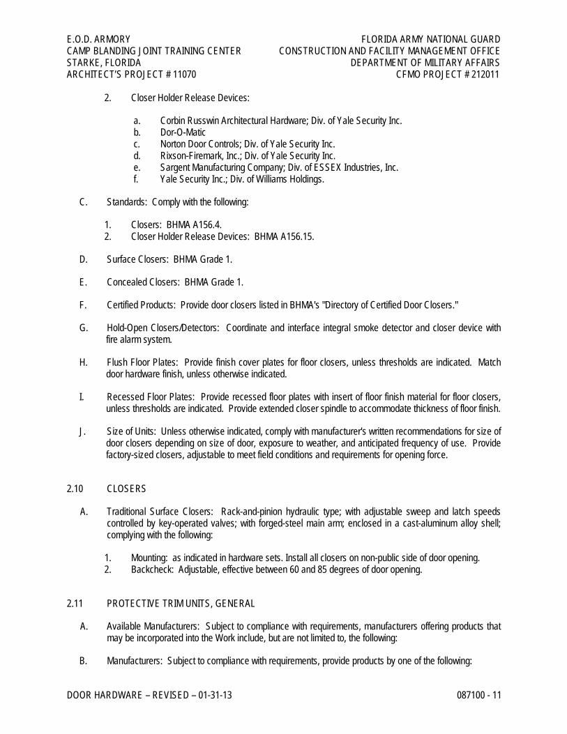
2. Closer Holder Release Devices:
a. Corbin Russwin Architectural Hardware; Div. of Yale Security Inc. b. Dor-O-Matic c. Norton Door Controls; Div. of Yale Security Inc. d. Rixson-Firemark, Inc.; Div. of Yale Security Inc. e. Sargent Manufacturing Company; Div. of ESSEX Industries, Inc. f. Yale Security Inc.; Div. of Williams Holdings.
C. Standards: Comply with the following:
1. Closers: BHMA A156.4. 2. Closer Holder Release Devices: BHMA A156.15.
D. Surface Closers: BHMA Grade 1.
E. Concealed Closers: BHMA Grade 1.
F. Certified Products: Provide door closers listed in BHMA's "Directory of Certified Door Closers."
G. Hold-Open Closers/Detectors: Coordinate and interface integral smoke detector and closer device with fire alarm system.
H. Flush Floor Plates: Provide finish cover plates for floor closers, unless thresholds are indicated. Match door hardware finish, unless otherwise indicated.
I. Recessed Floor Plates: Provide recessed floor plates with insert of floor finish material for floor closers, unless thresholds are indicated. Provide extended closer spindle to accommodate thickness of floor finish.
J. Size of Units: Unless otherwise indicated, comply with manufacturer's written recommendations for size of door closers depending on size of door, exposure to weather, and anticipated frequency of use. Provide factory-sized closers, adjustable to meet field conditions and requirements for opening force.
2.10 CLOSERS
A. Traditional Surface Closers: Rack-and-pinion hydraulic type; with adjustable sweep and latch speeds controlled by key-operated valves; with forged-steel main arm; enclosed in a cast-aluminum alloy shell; complying with the following:
1. Mounting: as indicated in hardware sets. Install all closers on non-public side of door opening. 2. Backcheck: Adjustable, effective between 60 and 85 degrees of door opening.
2.11 PROTECTIVE TRIM UNITS, GENERAL
A. Available Manufacturers: Subject to compliance with requirements, manufacturers offering products that may be incorporated into the Work include, but are not limited to, the following:
B. Manufacturers: Subject to compliance with requirements, provide products by one of the following:
E.O.D. ARMORY FLORIDA ARMY NATIONAL GUARD CAMP BLANDING JOINT TRAINING CENTER CONSTRUCTION AND FACILITY MANAGEMENT OFFICE STARKE, FLORIDA DEPARTMENT OF MILITARY AFFAIRS ARCHITECT’S PROJECT # 11070 CFMO PROJECT # 212011
DOOR HARDWARE – REVISED – 01-31-13 087100 - 12
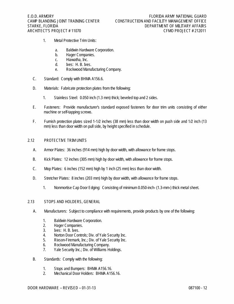
1. Metal Protective Trim Units:
a. Baldwin Hardware Corporation. b. Hager Companies. c. Hiawatha, Inc. d. Ives: H. B. Ives. e. Rockwood Manufacturing Company.
C. Standard: Comply with BHMA A156.6.
D. Materials: Fabricate protection plates from the following:
1. Stainless Steel: 0.050 inch (1.3 mm) thick; beveled top and 2 sides.
E. Fasteners: Provide manufacturer's standard exposed fasteners for door trim units consisting of either machine or self-tapping screws.
F. Furnish protection plates sized 1-1/2 inches (38 mm) less than door width on push side and 1/2 inch (13 mm) less than door width on pull side, by height specified in schedule.
2.12 PROTECTIVE TRIM UNITS
A. Armor Plates: 36 inches (914 mm) high by door width, with allowance for frame stops.
B. Kick Plates: 12 inches (305 mm) high by door width, with allowance for frame stops.
C. Mop Plates: 6 inches (152 mm) high by 1 inch (25 mm) less than door width.
D. Stretcher Plates: 8 inches (203 mm) high by door width, with allowance for frame stops.
1. Nonmortise Cap Door Edging: Consisting of minimum 0.050-inch- (1.3-mm-) thick metal sheet.
2.13 STOPS AND HOLDERS, GENERAL
A. Manufacturers: Subject to compliance with requirements, provide products by one of the following:
1. Baldwin Hardware Corporation. 2. Hager Companies. 3. Ives: H. B. Ives. 4. Norton Door Controls; Div. of Yale Security Inc. 5. Rixson-Firemark, Inc.; Div. of Yale Security Inc. 6. Rockwood Manufacturing Company. 7. Yale Security Inc.; Div. of Williams Holdings.
B. Standards: Comply with the following:
1. Stops and Bumpers: BHMA A156.16. 2. Mechanical Door Holders: BHMA A156.16.
E.O.D. ARMORY FLORIDA ARMY NATIONAL GUARD CAMP BLANDING JOINT TRAINING CENTER CONSTRUCTION AND FACILITY MANAGEMENT OFFICE STARKE, FLORIDA DEPARTMENT OF MILITARY AFFAIRS ARCHITECT’S PROJECT # 11070 CFMO PROJECT # 212011
DOOR HARDWARE – REVISED – 01-31-13 087100 - 13
3. Electromagnetic Door Holders: BHMA A156.15. 4. Combination Overhead Holders and Stops: BHMA A156.8. 5. Door Silencers: BHMA A156.16.
C. Floor Stops: For doors, unless wall or other type stops are scheduled or indicated. Do not mount floor stops where they will impede traffic.
1. Where floor or wall stops are not appropriate, provide overhead holders.
D. Silencers for Metal Door Frames: BHMA Grade 1; neoprene or rubber, minimum diameter 1/2 inch (13 mm); fabricated for drilled-in application to frame.
2.14 STOPS AND HOLDERS
A. Rigid Wall Stops: Polished cast brass, bronze, or aluminum; 3-1/2 inches (89 mm) long, with rubber bumper; expansion-shield application.
B. Wall Bumpers: Polished cast brass or aluminum with rubber bumper; 2-1/2-inch (64-mm) diameter, minimum 3/4-inch (19-mm) projection from wall, with backplate for concealed fastener installation.
C. Roller-Type Bumpers: Polished cast brass or bronze; minimum 4-3/8-inch (111-mm) projection from wall; attached by surface screws.
D. Rigid Floor Stop: Polished cast brass, bronze, or aluminum, with rubber bumper; expansion-shield application.
E. Dome-Type Floor Stop: Polished cast brass, bronze, or aluminum, with rubber bumper; and as follows:
1. Height: Minimum 1 inch (25 mm) high, for doors without threshold, 1-3/8 inches (35 mm) high, for doors with threshold.
2. Riser: Extruded aluminum for carpet installations.
F. Lever-Type Door Holders: Polished cast brass, bronze, or aluminum; consisting of 4-inch- (102-mm-) long arm that swings up and remains in vertical position; with replaceable rubber tip; surface-screw application.
G. Plunger-Type Door Holders: Polished cast brass, bronze, or aluminum; minimum 1-1/8-inch (29-mm) plunger throw; with replaceable rubber tip; surface-screw application.
2.15 DOOR GASKETING, GENERAL
A. Manufacturers: Subject to compliance with requirements, provide products by one of the following:
1. Door Gasketing:
a. Hager Companies. b. National Guard Products, Inc. c. Pemko Manufacturing Co., Inc.
E.O.D. ARMORY FLORIDA ARMY NATIONAL GUARD CAMP BLANDING JOINT TRAINING CENTER CONSTRUCTION AND FACILITY MANAGEMENT OFFICE STARKE, FLORIDA DEPARTMENT OF MILITARY AFFAIRS ARCHITECT’S PROJECT # 11070 CFMO PROJECT # 212011
DOOR HARDWARE – REVISED – 01-31-13 087100 - 14
2. Door Bottoms:
a. Hager Companies. b. National Guard Products, Inc. c. Pemko Manufacturing Co., Inc.
B. General: Provide continuous weather-strip gasketing on exterior doors and provide smoke, light, or sound gasketing on interior doors where indicated or scheduled. Provide noncorrosive fasteners for exterior applications and elsewhere as indicated.
1. Perimeter Gasketing: Apply to head and jamb, forming seal between door and frame. 2. Meeting Stile Gasketing: Fasten to meeting stiles, forming seal when doors are closed. 3. Door Bottoms: Apply to bottom of door, forming seal with threshold when door is closed.
C. Air Leakage: Not to exceed 0.50 cfm per foot (0.000774 cu. m/s per m) of crack length for gasketing other than for smoke control, as tested according to ASTM E 283.
D. Smoke-Labeled Gasketing: Assemblies complying with NFPA 105 that are listed and labeled by a testing and inspecting agency acceptable to authorities having jurisdiction, for smoke-control ratings indicated, based on testing according to UL 1784.
1. Provide smoke-labeled gasketing on 20-minute-rated doors and on smoke-labeled doors.
E. Fire-Labeled Gasketing: Assemblies complying with NFPA 80 that are listed and labeled by a testing and inspecting agency acceptable to authorities having jurisdiction, for fire ratings indicated, based on testing according to UL 10B or NFPA 252.
F. Sound-Rated Gasketing: Assemblies that are listed and labeled by a testing and inspecting agency, for sound ratings indicated, based on testing according to ASTM E 1408.
G. Replaceable Seal Strips: Provide only those units where resilient or flexible seal strips are easily replaceable and readily available from stocks maintained by manufacturer.
H. Gasketing Materials: Comply with ASTM D 2000 and AAMA 701/702.
2.16 DOOR GASKETING
A. Adhesive-Backed Perimeter Gasketing: Gasket material applied to frame rabbet with self-adhesive.
1. Gasket Material: Silicone.
B. Rigid, Housed Perimeter Gasketing: Gasket material held in place by metal housing; fastened to frame stop with screws.
1. Gasket Material: Silicone bulb. 2. Housing Material: Aluminum.
C. Door Sweeps: Gasket material held in place by flat metal housing or flange; surface mounted to face of door with screws.
E.O.D. ARMORY FLORIDA ARMY NATIONAL GUARD CAMP BLANDING JOINT TRAINING CENTER CONSTRUCTION AND FACILITY MANAGEMENT OFFICE STARKE, FLORIDA DEPARTMENT OF MILITARY AFFAIRS ARCHITECT’S PROJECT # 11070 CFMO PROJECT # 212011
DOOR HARDWARE – REVISED – 01-31-13 087100 - 15
1. Gasket Material: Vinyl. 2. Housing Material: Aluminum.
2.17 THRESHOLDS, GENERAL
A. Manufacturers: Subject to compliance with requirements, provide products by one of the following:
1. Hager Companies. 2. National Guard Products, Inc. 3. Pemko Manufacturing Co., Inc.
B. Standard: Comply with BHMA A156.21.
2.18 THRESHOLDS
A. Compressing-Top Thresholds: Metal member with compressible vinyl seal on top of threshold that seals against bottom of door; and base metal of aluminum.
B. Saddle Thresholds: Type and base metal as follows:
1. Type: Fluted top. 2. Base Metal: Aluminum
2.19 FABRICATION
A. Manufacturer's Nameplate: Do not provide manufacturers' products that have manufacturer's name or trade name displayed in a visible location (omit removable nameplates) except in conjunction with required fire-rated labels and as otherwise approved by Architect.
1. Manufacturer's identification will be permitted on rim of lock cylinders only.
B. Base Metals: Produce door hardware units of base metal, fabricated by forming method indicated, using manufacturer's standard metal alloy, composition, temper, and hardness. Furnish metals of a quality equal to or greater than that of specified door hardware units and BHMA A156.18 for finishes. Do not furnish manufacturer's standard materials or forming methods if different from specified standard.
C. Fasteners: Provide door hardware manufactured to comply with published templates generally prepared for machine, wood, and sheet metal screws. Provide screws according to commercially recognized industry standards for application intended. Provide Phillips flat-head screws with finished heads to match surface of door hardware, unless otherwise indicated.
1. Concealed Fasteners: For door hardware units that are exposed when door is closed, except for units already specified with concealed fasteners. Do not use through bolts for installation where bolt head or nut on opposite face is exposed unless it is the only means of securely attaching the door hardware. Where through bolts are used on hollow door and frame construction, provide sleeves for each through bolt.
2. Steel Machine or Wood Screws: For the following fire-rated applications:
E.O.D. ARMORY FLORIDA ARMY NATIONAL GUARD CAMP BLANDING JOINT TRAINING CENTER CONSTRUCTION AND FACILITY MANAGEMENT OFFICE STARKE, FLORIDA DEPARTMENT OF MILITARY AFFAIRS ARCHITECT’S PROJECT # 11070 CFMO PROJECT # 212011
DOOR HARDWARE – REVISED – 01-31-13 087100 - 16
a. Mortise hinges to doors. b. Strike plates to frames. c. Closers to doors and frames.
3. Steel Through Bolts: For the following fire-rated applications, unless door blocking is provided:
a. Surface hinges to doors. b. Closers to doors and frames. c. Surface-mounted exit devices.
4. Spacers or Sex Bolts: For through bolting of hollow metal doors.
2.20 FINISHES
A. Standard: Comply with BHMA A156.18.
B. Protect mechanical finishes on exposed surfaces from damage by applying a strippable, temporary protective covering before shipping.
C. Appearance of Finished Work: Variations in appearance of abutting or adjacent pieces are acceptable if they are within one-half of the range of approved Samples. Noticeable variations in the same piece are not acceptable. Variations in appearance of other components are acceptable if they are within the range of approved Samples and are assembled or installed to minimize contrast.
D. BHMA Designations: Comply with base material and finish requirements indicated by the following:
1. BHMA 600: Primed for painting, over steel base metal. 2. BHMA 626: Satin chromium plated over nickel, over brass or bronze base metal. 3. BHMA 630: Satin stainless steel, over stainless-steel base metal. 4. BHMA 689: Aluminum painted, over any base metal.
2.21 EXAMINATION
A. Examine doors and frames, with Installer present, for compliance with requirements for installation tolerances, labeled fire door assembly construction, wall and floor construction, and other conditions affecting performance of door hardware.
B. Examine roughing-in for electrical power systems to verify actual locations of wiring connections before electrified door hardware installation.
C. Proceed with installation only after unsatisfactory conditions have been corrected.
2.22 PREPARATION
A. Steel Doors and Frames: Comply with DHI A115 series.
1. Surface-Applied Door Hardware: Drill and tap doors and frames according to SDI 107.
E.O.D. ARMORY FLORIDA ARMY NATIONAL GUARD CAMP BLANDING JOINT TRAINING CENTER CONSTRUCTION AND FACILITY MANAGEMENT OFFICE STARKE, FLORIDA DEPARTMENT OF MILITARY AFFAIRS ARCHITECT’S PROJECT # 11070 CFMO PROJECT # 212011
DOOR HARDWARE – REVISED – 01-31-13 087100 - 17
2.23 INSTALLATION
A. Mounting Heights: Mount door hardware units at heights indicated in following applicable publications, unless specifically indicated or required to comply with governing regulations:
1. Standard Steel Doors and Frames: DHI's "Recommended Locations for Architectural Hardware for Standard Steel Doors and Frames."
2. Custom Steel Doors and Frames: DHI's "Recommended Locations for Builders' Hardware for Custom Steel Doors and Frames."
3. Wood Doors: DHI WDHS.3, "Recommended Locations for Architectural Hardware for Wood Flush Doors."
B. Install each door hardware item to comply with manufacturer's written instructions. Where cutting and fitting are required to install door hardware onto or into surfaces that are later to be painted or finished in another way, coordinate removal, storage, and reinstallation of surface protective trim units with finishing work specified in Division 9 Sections. Do not install surface-mounted items until finishes have been completed on substrates involved.
1. Set units level, plumb, and true to line and location. Adjust and reinforce attachment substrates as necessary for proper installation and operation.
2. Drill and countersink units that are not factory prepared for anchorage fasteners. Space fasteners and anchors according to industry standards.
C. Key Control System: Place keys on markers and hooks in key control system cabinet, as determined by final keying schedule.
D. Thresholds: Set thresholds for exterior and acoustical doors in full bed of sealant complying with requirements specified in Division 7 Section "Joint Sealants."
2.24 FIELD QUALITY CONTROL
A. Independent Architectural Hardware Consultant: Owner may engage a qualified independent Architectural Hardware Consultant to perform inspections and to prepare inspection reports.
1. Independent Architectural Hardware Consultant will inspect door hardware and state in each report whether installed work complies with or deviates from requirements, including whether door hardware is properly installed and adjusted.
2.25 CLEANING AND PROTECTION
A. Clean adjacent surfaces soiled by door hardware installation.
B. Clean operating items as necessary to restore proper function and finish.
C. Provide final protection and maintain conditions that ensure door hardware is without damage or deterioration at time of Substantial Completion.
E.O.D. ARMORY FLORIDA ARMY NATIONAL GUARD CAMP BLANDING JOINT TRAINING CENTER CONSTRUCTION AND FACILITY MANAGEMENT OFFICE STARKE, FLORIDA DEPARTMENT OF MILITARY AFFAIRS ARCHITECT’S PROJECT # 11070 CFMO PROJECT # 212011
DOOR HARDWARE – REVISED – 01-31-13 087100 - 18
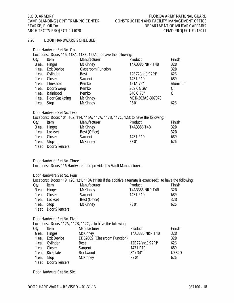
2.26 DOOR HARDWARE SCHEDULE
Door Hardware Set No. One Locations: Doors 115, 118A, 118B, 122A; to have the following: Qty. Item Manufacturer Product Finish 3 ea. Hinges McKinney T4A3386 NRP T4B 32D 1 ea. Exit Device Classroom Function 32D 1 ea. Cylinder Best 12E72(std.) S2RP 626 1 ea. Closer Sargent 1431-P10 689 1 ea. Threshold Pemko 151A 72” Aluminum 1 ea. Door Sweep Pemko 368 CN 36” C 1 ea. Rainhood Pemko 346 C 76” C 1 ea. Door Gasketing McKinney MCK-303AS-307070 1 ea. Stop McKinney FS01 626 Door Hardware Set No. Two Locations: Doors 101, 102, 114, 115A, 117A, 117B, 117C, 123; to have the following: Qty. Item Manufacturer Product Finish 3 ea. Hinges McKinney T4A3386 T4B 32D 1 ea. Lockset Best (Office) 32D 1 ea. Closer Sargent 1431-P10 689 1 ea. Stop McKinney FS01 626 1 set Door Silencers Door Hardware Set No. Three Locations: Doors 116 Hardware to be provided by Vault Manufacturer. Door Hardware Set No. Four Locations: Doors 119, 120, 121, 113A (118B if the additive alternate is exercised); to have the following: Qty. Item Manufacturer Product Finish 3 ea. Hinges McKinney T4A3386 NRP T4B 32D 1 ea. Closer Sargent 1431-P10 689 1 ea. Lockset Best (Office) 32D 1 ea. Stop McKinney FS01 626 1 set Door Silencers Door Hardware Set No. Five Locations: Doors 112A, 112B, 112C, : to have the following: Qty. Item Manufacturer Product Finish 6 ea. Hinges McKinney T4A3386 NRP T4B 32D 1 ea. Exit Device ED5200S (Classroom Function) 32D 1 ea. Cylinder Best 12E72(std.) S2RP 626 1 ea. Closer Sargent 1431-P10 689 1 ea. Kickplate Rockwood 8” x 34” US32D 1 ea. Stop McKinney FS01 626 1 set Door Silencers Door Hardware Set No. Six
E.O.D. ARMORY FLORIDA ARMY NATIONAL GUARD CAMP BLANDING JOINT TRAINING CENTER CONSTRUCTION AND FACILITY MANAGEMENT OFFICE STARKE, FLORIDA DEPARTMENT OF MILITARY AFFAIRS ARCHITECT’S PROJECT # 11070 CFMO PROJECT # 212011
DOOR HARDWARE – REVISED – 01-31-13 087100 - 19
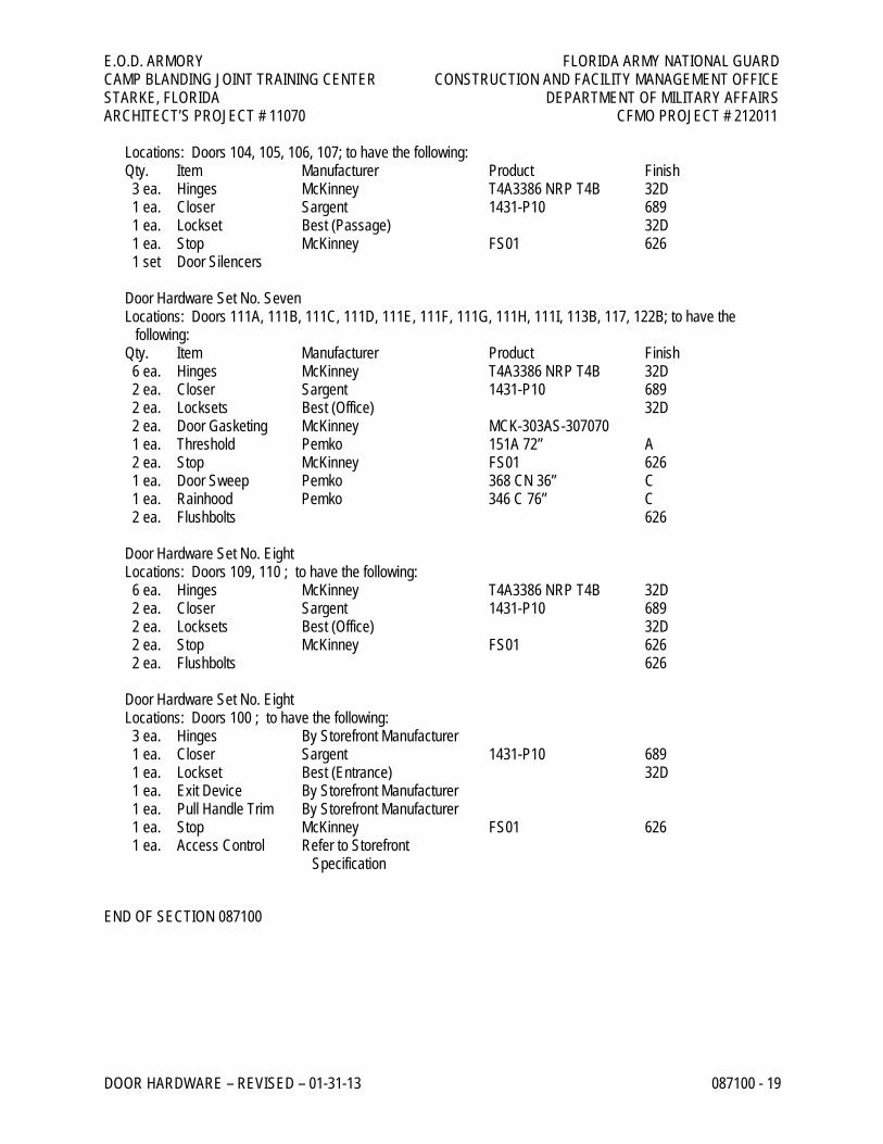
Locations: Doors 104, 105, 106, 107; to have the following: Qty. Item Manufacturer Product Finish 3 ea. Hinges McKinney T4A3386 NRP T4B 32D 1 ea. Closer Sargent 1431-P10 689 1 ea. Lockset Best (Passage) 32D 1 ea. Stop McKinney FS01 626 1 set Door Silencers Door Hardware Set No. Seven Locations: Doors 111A, 111B, 111C, 111D, 111E, 111F, 111G, 111H, 111I, 113B, 117, 122B; to have the
following: Qty. Item Manufacturer Product Finish 6 ea. Hinges McKinney T4A3386 NRP T4B 32D 2 ea. Closer Sargent 1431-P10 689 2 ea. Locksets Best (Office) 32D 2 ea. Door Gasketing McKinney MCK-303AS-307070 1 ea. Threshold Pemko 151A 72” A 2 ea. Stop McKinney FS01 626 1 ea. Door Sweep Pemko 368 CN 36” C 1 ea. Rainhood Pemko 346 C 76” C 2 ea. Flushbolts 626 Door Hardware Set No. Eight Locations: Doors 109, 110 ; to have the following: 6 ea. Hinges McKinney T4A3386 NRP T4B 32D 2 ea. Closer Sargent 1431-P10 689 2 ea. Locksets Best (Office) 32D 2 ea. Stop McKinney FS01 626 2 ea. Flushbolts 626 Door Hardware Set No. Eight Locations: Doors 100 ; to have the following: 3 ea. Hinges By Storefront Manufacturer 1 ea. Closer Sargent 1431-P10 689 1 ea. Lockset Best (Entrance) 32D 1 ea. Exit Device By Storefront Manufacturer 1 ea. Pull Handle Trim By Storefront Manufacturer 1 ea. Stop McKinney FS01 626 1 ea. Access Control Refer to Storefront
Specification
END OF SECTION 087100
E.O.D. ARMORY FLORIDA ARMY NATIONAL GUARD CAMP BLANDING JOINT TRAINING CENTER CONSTRUCTION AND FACILITY MANAGEMENT OFFICE STARKE, FLORIDA DEPARTMENT OF MILITARY AFFAIRS ARCHITECT’S PROJECT # 11070 CFMO PROJECT # 212011
MODULAR VAULT SYSTEM – REVISED – 01-31-13 139110 - 1
SECTION 139110 – MODULAR VAULT SYSTEM – REVISED – 01-31-13
PART 1 - GENERAL
1.1 RELATED DOCUMENTS
A. Drawings and general provisions of the Contract, including General and Supplementary Conditions and Division 1 Specification Sections, apply to this Section.
1.2 SUMMARY
A. This Section includes prefabricated modular Type II panel vault system and vault door.
1. Note: Vault is to be painted inside and out, coordinate with paint and preparation requirements.
B. Related Sections include the following:
1. Division 9 Section “Painting” for painting vault system – exterior and interior. 2. Division 15 Sections for HVAC systems and connections to modular vault. 3. Division 16 Sections for electrical wiring, communication wiring, alarm wiring and connections for
modular vault.
1.3 PERFORMANCE REQUIREMENTS
A. Modular Vault Performance: Provide modular concrete panel vault system that complies with:
1. GSA AA-V-2737.
B. Vault Door Performance: Provide vault door that complies with:
1. GSA Security Class-5 for armory installation.
1.4 SUBMITTALS
A. Product Data: Include construction details, material descriptions, dimensions of individual components and profiles, and finishes for vault.
B. Shop Drawings: Include plans, elevations, sections, details, and attachments to other work.
C. Assurance/Control Submittals:
1. Test Reports: Underwriters Laboratories Incorporated (UL) approval for type 608 Class M vault with General Services Administration (GSA) security Class 5 standards for vault door.
E.O.D. ARMORY FLORIDA ARMY NATIONAL GUARD CAMP BLANDING JOINT TRAINING CENTER CONSTRUCTION AND FACILITY MANAGEMENT OFFICE STARKE, FLORIDA DEPARTMENT OF MILITARY AFFAIRS ARCHITECT’S PROJECT # 11070 CFMO PROJECT # 212011
MODULAR VAULT SYSTEM – REVISED – 01-31-13 139110 - 2
D. Field Painting Assurance: General Contractor to submit painting schedule indicating paint and number of coats for modular vault system.
1.5 QUALITY ASSURANCE
A. Source Limitations: Obtain modular vault through one source from a single manufacturer.
B. Product Options: Information on Drawings and in Specifications establishes requirements for system’s performance characteristics.
C. Welding: Qualify procedures and personnel according to the following:
1. AWS D1.1, “Structural Welding Code--Steel.”
D. Preinstallation Conference: Conduct conference at Project site with Department of Military Affairs CFMO representative, local armory personnel, representatives of mechanical and electrical trade subcontractors and general contractor prior to installation.
1. General Contractor to conduct and record meeting via minutes of meeting and distribute to all attendees and architect.
1.6 PROJECT CONDITIONS
A. Field Measurements: Verify actual locations of walls, columns, and other construction contiguous with modular vault by field measurements before fabrication and indicate measurements on Shop Drawings.
PART 2 - PRODUCTS
2.1 MANUFACTURERS
A. In other Part 2 articles where titles below introduce lists, the following requirements apply to product selection:
1. Basis-of-Design Product: The design for type of modular vault indicated is based on the product named. Subject to compliance with requirements, provide either the named product or a comparable product by one of the other manufacturers specified.
2.2 MODULAR VAULT, GENERAL
A. General: Provide a complete, integrated set of manufacturer’s standard, mutually dependent components that form a completely assembled, prefabricated concrete panel modular vault, ready for installation on Project site. Include structural framing, roof and wall panels, door(s), and accessories complying with requirements indicated.
1. Vault Standard: Meeting Federal Specification GSA AA-V-2737.
E.O.D. ARMORY FLORIDA ARMY NATIONAL GUARD CAMP BLANDING JOINT TRAINING CENTER CONSTRUCTION AND FACILITY MANAGEMENT OFFICE STARKE, FLORIDA DEPARTMENT OF MILITARY AFFAIRS ARCHITECT’S PROJECT # 11070 CFMO PROJECT # 212011
MODULAR VAULT SYSTEM – REVISED – 01-31-13 139110 - 3
2. Doors: Standard meeting GSA Security Class 5 standards for armory installation.
B. Lighting Fixtures: Provided for under Division 16 Electrical Specifications.
2.3 MODULAR VAULT AND DOOR SYSTEM
A. Basis-of-Design Product: Custom Vault Corporation; UL rated Class M (GSA AA-V-2737) prefabricated concrete panel modular vault.
B. Vault Panel System: Modular interlocking vault system consisting of 4” thick concrete panels for slab on grade installation.
1. Utility Entrances: Provide three junction boxes with six conduits through ceiling panel or at location as required by vault manufacturer. General Contractor to provide three junction boxes for access conduit. Manufacturer and General Contractor and Electrical Sub-contractor to verify all penetrations shown on the vault system so as to provide complete system prior to fabrication.
2. Ventilation: Provide ventilating system penetrations meeting UL standard 680. Manufacturer and General Contractor and Mechanical Sub-contractor to verify all penetrations shown on the vault system so as to provide complete system prior to fabrication.
3. Panel Connections: Vault panels shall be welded together in accordance with manufacturer’s requirements for secure welding. Vault systems shall be attached to floor slab with connection angel.
C. Door System: Conform to GSA Security Class-5 standards.
1. Approval label shall state, in white letters on red background: Approved by GSA for security vault door meeting Class 5 security standards.
2. Door Size: Clear Opening 40” x 78”.
D. Finish: Finish exposed surfaces, including structural framework, walls, and ceiling by manufacturer’s standard ready for field painting.
1. Field Painting: Prepare and paint, painting by Division 9 Painting.
2.4 FINISHES
A. Vault system panels and door systems interior and exterior to be final painted under Division 9 Painting.
PART 3 - EXECUTION
3.1 EXAMINATION
A. Examine substrates, areas, and conditions, with installer present, for compliance with requirements for installation tolerances and other conditions affecting performance.
E.O.D. ARMORY FLORIDA ARMY NATIONAL GUARD CAMP BLANDING JOINT TRAINING CENTER CONSTRUCTION AND FACILITY MANAGEMENT OFFICE STARKE, FLORIDA DEPARTMENT OF MILITARY AFFAIRS ARCHITECT’S PROJECT # 11070 CFMO PROJECT # 212011
MODULAR VAULT SYSTEM – REVISED – 01-31-13 139110 - 4
1. For the record, prepare written report, endorsed by installer, listing conditions detrimental to performance.
2. Proceed with installation only after unsatisfactory conditions have been corrected.
3.2 INSTALLATION
A. Install modular vault on existing concrete pad as per manufacturer’s requirements.
B. Set modular vault plumb and aligned.
C. Fasten modular vault panels by welding.
D. Connect electrical power service to power distribution system according to requirements specified in Division 16.
3.3 ADJUSTING AND CLEANING
A. Adjust doors and hardware to operate smoothly, easily, properly, and without binding. Confirm that locks engage accurately and securely without forcing or binding.
B. Lubricate hardware and other moving parts.
C. After completing installation, inspect exposed finishes and repair damaged finishes.
END OF SECTION 139110


![[Zing-man] Armory Castle](https://img.pdfslide.us/doc/110x75/55cf865b550346484b96d8d8/zing-man-armory-castle.jpg)