Embed Size (px)
DESCRIPTION
Eoc Training Module
Citation preview
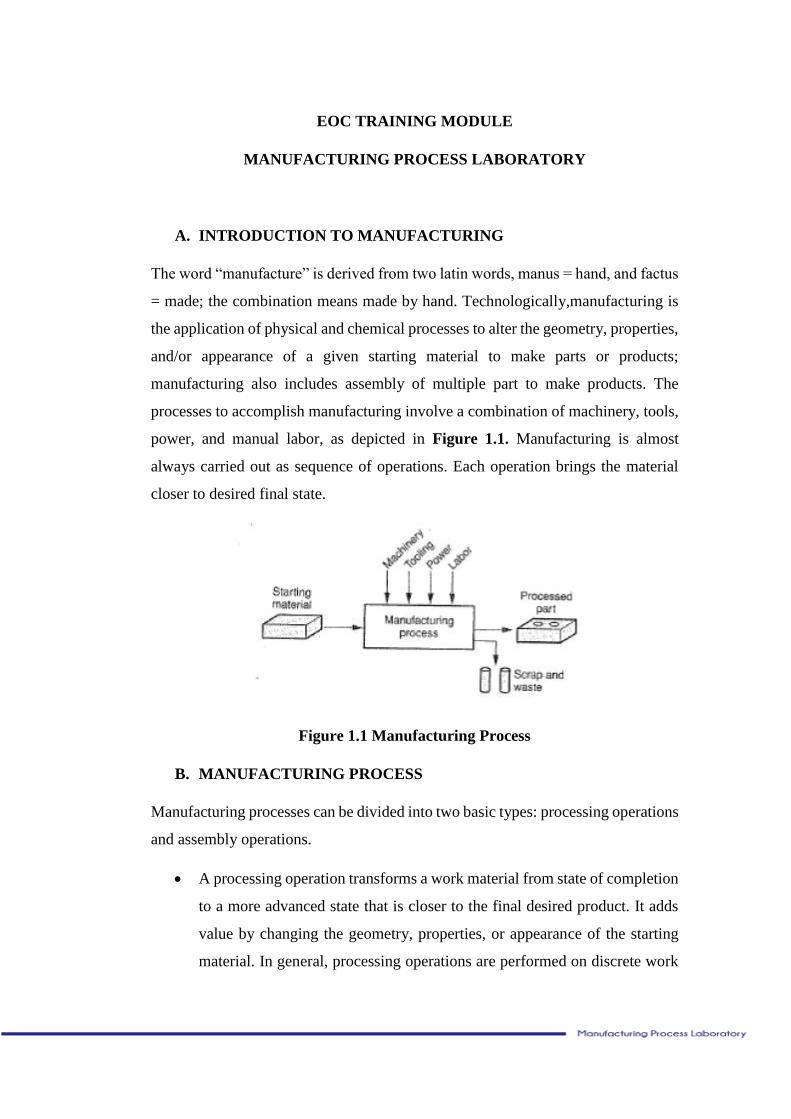
EOC TRAINING MODULE
MANUFACTURING PROCESS LABORATORY
A. INTRODUCTION TO MANUFACTURING
The word “manufacture” is derived from two latin words, manus = hand, and factus
= made; the combination means made by hand. Technologically,manufacturing is
the application of physical and chemical processes to alter the geometry, properties,
and/or appearance of a given starting material to make parts or products;
manufacturing also includes assembly of multiple part to make products. The
processes to accomplish manufacturing involve a combination of machinery, tools,
power, and manual labor, as depicted in Figure 1.1. Manufacturing is almost
always carried out as sequence of operations. Each operation brings the material
closer to desired final state.
Figure 1.1 Manufacturing Process
B. MANUFACTURING PROCESS
Manufacturing processes can be divided into two basic types: processing operations
and assembly operations.
A processing operation transforms a work material from state of completion
to a more advanced state that is closer to the final desired product. It adds
value by changing the geometry, properties, or appearance of the starting
material. In general, processing operations are performed on discrete work
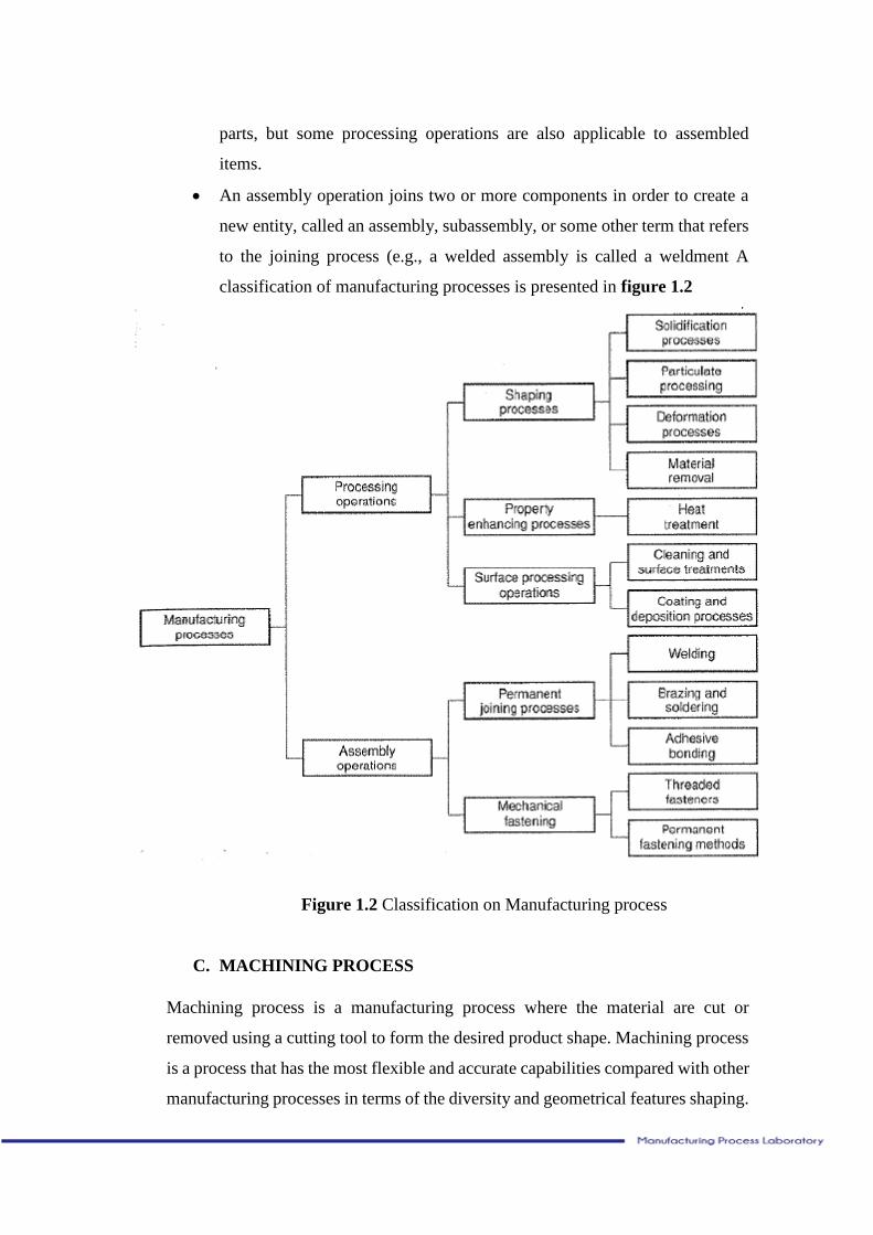
parts, but some processing operations are also applicable to assembled
items.
An assembly operation joins two or more components in order to create a
new entity, called an assembly, subassembly, or some other term that refers
to the joining process (e.g., a welded assembly is called a weldment A
classification of manufacturing processes is presented in figure 1.2
Figure 1.2 Classification on Manufacturing process
C. MACHINING PROCESS
Machining process is a manufacturing process where the material are cut or
removed using a cutting tool to form the desired product shape. Machining process
is a process that has the most flexible and accurate capabilities compared with other
manufacturing processes in terms of the diversity and geometrical features shaping.
Machining process is divided into three categories :
a. Conventional cutting process. Is a machining process that used a cutting tool
with a particular geometry. Three main processes that are often done by this
process is turning, drilling, and milling.
b. Abrasive Process. Is a material removal process using abrasive material,
such as grinding process.
c. Non-traditional machining processes. This processes are carried out with
electrics chemical and with the help of optical power source.
D. GEOMETRIC MODELING IN CAD/ CAM SOFTWARE
The most important aspect of the product is the geometric design (including sizes
and shapes). The design is so important due to specify the tools, machines, materials
and manufacturing processes to be used. The design of the product should be made
in detail and must consider various other aspects related. Designing products with
the manual method will lead to higher costs and will spend a long time. To
overcome these problems, the design should be created in a geometric model by
using computer. Among the usages of computer in manufacturing, Computer Aided
Design and Computer Aided Manufacturing (CAD/CAM) are by the far the best
known as well the best applications to create,modify, analyze, and optimize the
product design then translate it to real object.
Computer Aided Design (CAD)
CAD may be defined as a design processing using sophisticated computer graphics
technique, backed by computer software packages, to aid in the analytical,
development, costing, and ergonomic problems associated with design work. the
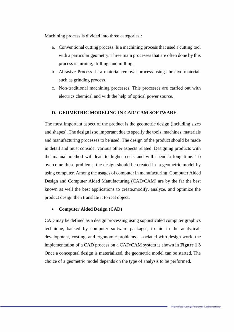
implementation of a CAD process on a CAD/CAM system is shown in Figure 1.3
Once a conceptual design is materialized, the geometric model can be started. The
choice of a geometric model depends on the type of analysis to be performed.
Figure 1.3 The CAD Process
(Source: Alvala, 2008,p.4)
Computer-aided Design (CAD) is defined as any design activity that involves the
effective use of the computer to create, modify, analyze, or document an
engineering design. CAD is most commonly asociated with the use of an interactive
computer graphics system, referred to as CAD system (Groover,2007).
There are various types of geometric models used in CAD, there are :
a. Two-dimensional (2-D) models
In two dimensions the drawings are built up with basic element as lines,
circle bows, curves and text. Two dimensions CAD drawings are obtained
through that the solid model is projected on a plane in a coordinat system.
b. Three-dimensional (3-D) models
In three dimensions one builds up models with curves, surfaces, or solid
models, depending on if you need wire frame, solid or surface model. By
adapting an orig one can obtain a projected image of the model. Surface and
solid modelling are important in engineering industry. Surface modelling
has been used for designing curves surfaces in shipping and consuming
products.
A typical CAD system consists of CAD software program. The software are :
AutoCAD, Catia, Cadkey, Hobbyists, and Solidwork
COMPUTER AIDED MANUFACTURING (CAM)
CAM maybe define as the use of computer system to plan, manage, and control the
operations of a manufacturing plant through either direct or indirect computer
interface with the production resource of the plant. The implementation of the CAM
process on the CAD/CAM system shown in Figure 1.4 . The geometric model
generated during the CAD process forms the basic for the CAM process with CAM
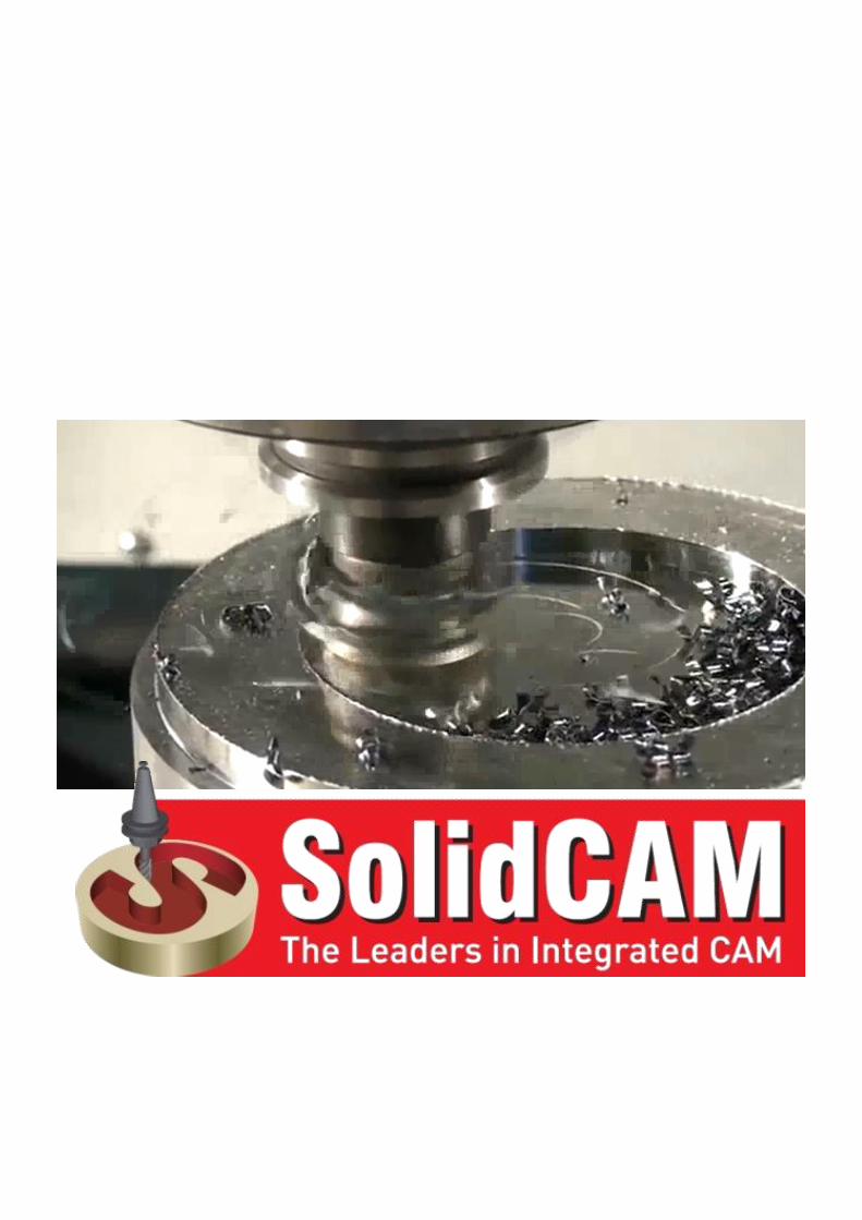
software, for example : SolidCAM or RhinoCAM. The output from CAM software
is NC Code, this code will b input for CNC machine for further processing into the
machine. Various activities in CAM may require different types ofinformation of
the CAD process. Interface algorithms are used to extract such information from
the CAD database. NC program, along with ordering tools and fixture, result from
process planning. once the parts are manufactured, computer-aided quality control
software is used to inspect the part. This is achieved by superposing an image of
the real part with a master image stored in its model database. After passing
inspection, all the parts are assembles by robots to result in the final product.
Computer-aided manufacturing, is using computers to prepare manufacturing of
parts and products. CAM usually regards to computeraided establishment of
program for Computer Numerical Control (CNC) machines, by using CAM
software. In the computer one creates the model of detail or product that is to be
manufactured and a model of the work piece. The program then establishes the tool
path, the way the tool goes over the work piece to create desired part/detail. CAM
is most efficient to be used with complex surfaces, complicated geometries and
curved surfaces.
In CAM software there are usually a simulation menu and options, where you can
simulate the operations you made in a program before machining it for real. In
simulations eventual coalitions in the operations and sequences can be discovered
and improvements can be done. Construction of parts or products is usually made
in CAD software, where drawings and models can be established. These models are
the ones to be used in CAM modelling as well. There is some sofware which is
integrated between CAD and CAM. The CAM software usually generates a cutter
line data (CLdata), to get the G-code languange or NC code. The sofware called
SolidCAM, RhinoCAM, etc
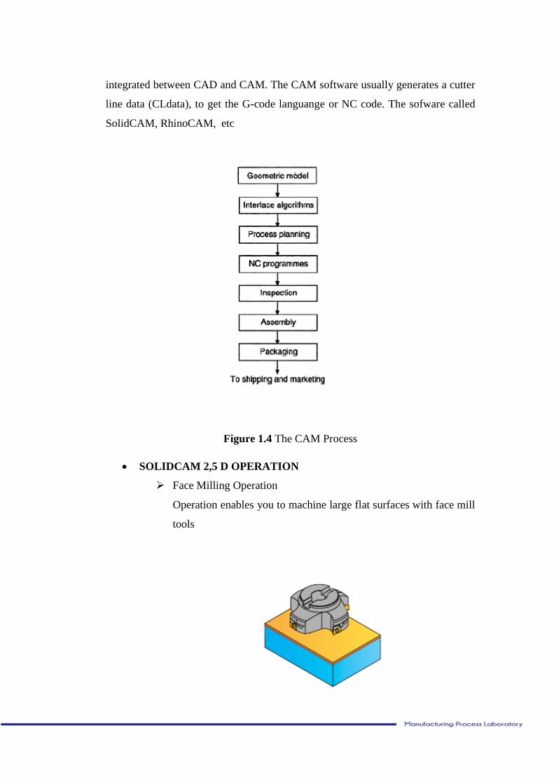
Figure 1.4 The CAM Process
SOLIDCAM 2,5 D OPERATION
Face Milling Operation
Operation enables you to machine large flat surfaces with face mill
tools
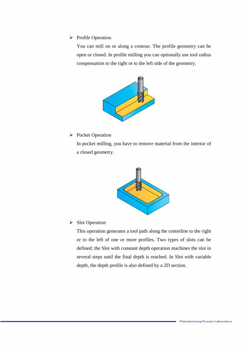
Profile Operation
You can mill on or along a contour. The profile geometry can be
open or closed. In profile milling you can optionally use tool radius
compensation to the right or to the left side of the geometry.
Pocket Operation
In pocket milling, you have to remove material from the interior of
a closed geometry.
Slot Operation
This operation generates a tool path along the centerline to the right
or to the left of one or more profiles. Two types of slots can be
defined: the Slot with constant depth operation machines the slot in
several steps until the final depth is reached. In Slot with variable
depth, the depth profile is also defined by a 2D section.
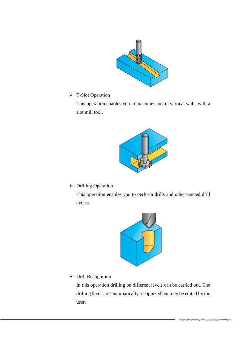
T-Slot Operation
This operation enables you to machine slots in vertical walls with a
slot mill tool.
Drilling Operation
This operation enables you to perform drills and other canned drill
cycles.
Drill Recognition
In this operation drilling on different levels can be carried out. The
drilling levels are automatically recognized but may be edited by the
user.
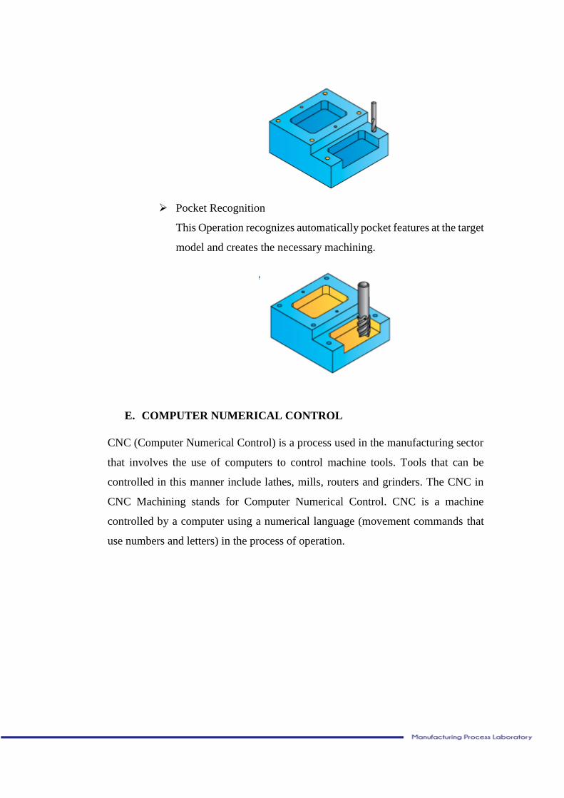
Pocket Recognition
This Operation recognizes automatically pocket features at the target
model and creates the necessary machining.
E. COMPUTER NUMERICAL CONTROL
CNC (Computer Numerical Control) is a process used in the manufacturing sector
that involves the use of computers to control machine tools. Tools that can be
controlled in this manner include lathes, mills, routers and grinders. The CNC in
CNC Machining stands for Computer Numerical Control. CNC is a machine
controlled by a computer using a numerical language (movement commands that
use numbers and letters) in the process of operation.
Figure 1.5 Computer Numerical Control
We can analogize the CNC machine as a printer. When we are going to make an
article, the things we do is made up in the computer first, then when it has finished,
we will print the article that we have made using the printer machine. Similarly,
when we are going to make a product, the first thing we do is creating an image of
the design on the computer, and when the design has been finished then we will
print the design using the CNC machine.
There are many advantages to using CNC Machining. The process is more precise
than manual machining, and can be repeated in exactly the same manner over and
over again. Because of the precision possible with CNC Machining, this process
can produce complex shapes that would be almost impossible to achieve with
manual machining. CNC Machining is used in the production of many complex
three-dimensional shapes.
F. TYPE OF CNC MACHINE
The CNC machines are divided into two kinds, they are:
a. 2 axis (CNC Lathe Machine)
Figure 1.6 CNC Lathe Machine
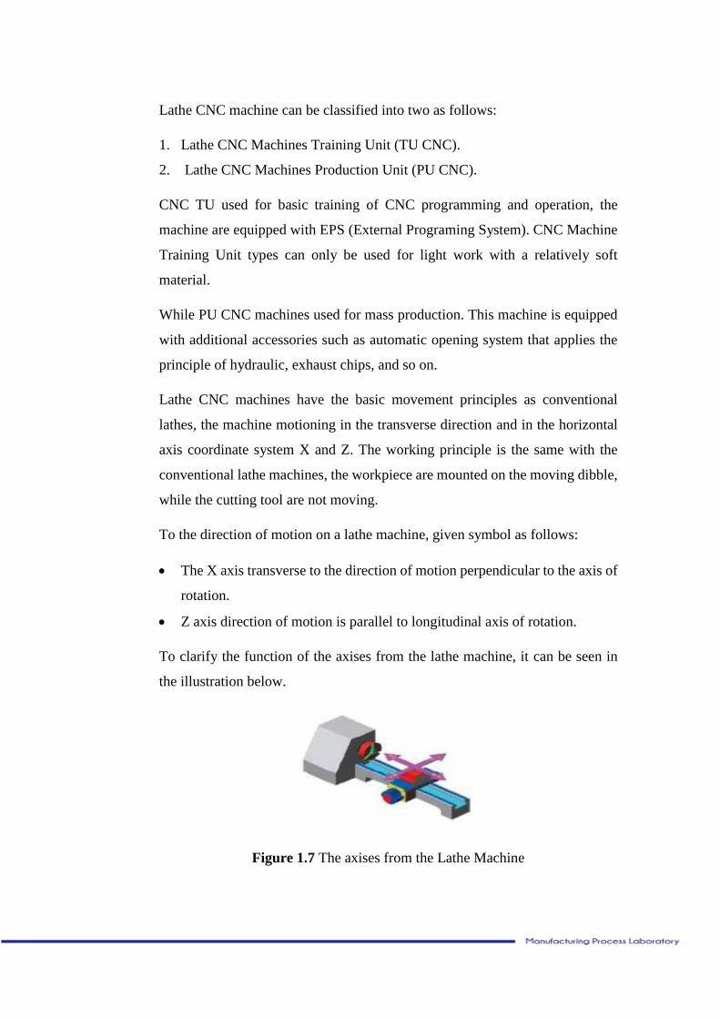
Lathe CNC machine can be classified into two as follows:
1. Lathe CNC Machines Training Unit (TU CNC).
2. Lathe CNC Machines Production Unit (PU CNC).
CNC TU used for basic training of CNC programming and operation, the
machine are equipped with EPS (External Programing System). CNC Machine
Training Unit types can only be used for light work with a relatively soft
material.
While PU CNC machines used for mass production. This machine is equipped
with additional accessories such as automatic opening system that applies the
principle of hydraulic, exhaust chips, and so on.
Lathe CNC machines have the basic movement principles as conventional
lathes, the machine motioning in the transverse direction and in the horizontal
axis coordinate system X and Z. The working principle is the same with the
conventional lathe machines, the workpiece are mounted on the moving dibble,
while the cutting tool are not moving.
To the direction of motion on a lathe machine, given symbol as follows:
The X axis transverse to the direction of motion perpendicular to the axis of
rotation.
Z axis direction of motion is parallel to longitudinal axis of rotation.
To clarify the function of the axises from the lathe machine, it can be seen in
the illustration below.
Figure 1.7 The axises from the Lathe Machine
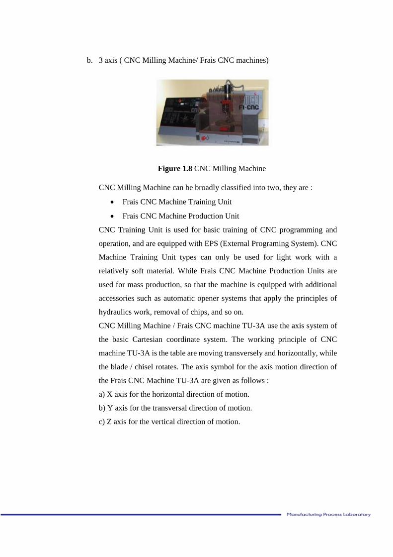
b. 3 axis ( CNC Milling Machine/ Frais CNC machines)
Figure 1.8 CNC Milling Machine
CNC Milling Machine can be broadly classified into two, they are :
Frais CNC Machine Training Unit
Frais CNC Machine Production Unit
CNC Training Unit is used for basic training of CNC programming and
operation, and are equipped with EPS (External Programing System). CNC
Machine Training Unit types can only be used for light work with a
relatively soft material. While Frais CNC Machine Production Units are
used for mass production, so that the machine is equipped with additional
accessories such as automatic opener systems that apply the principles of
hydraulics work, removal of chips, and so on.
CNC Milling Machine / Frais CNC machine TU-3A use the axis system of
the basic Cartesian coordinate system. The working principle of CNC
machine TU-3A is the table are moving transversely and horizontally, while
the blade / chisel rotates. The axis symbol for the axis motion direction of
the Frais CNC Machine TU-3A are given as follows :
a) X axis for the horizontal direction of motion.
b) Y axis for the transversal direction of motion.
c) Z axis for the vertical direction of motion.
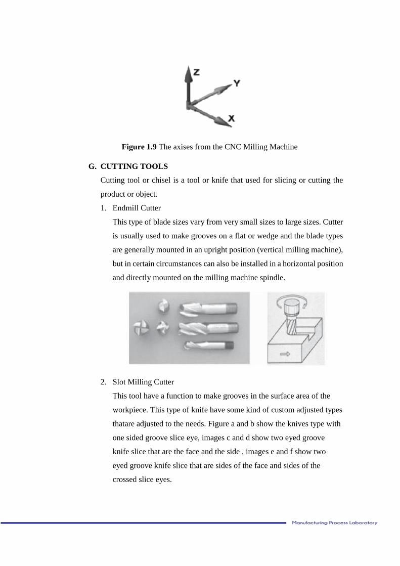
Figure 1.9 The axises from the CNC Milling Machine
G. CUTTING TOOLS
Cutting tool or chisel is a tool or knife that used for slicing or cutting the
product or object.
1. Endmill Cutter
This type of blade sizes vary from very small sizes to large sizes. Cutter
is usually used to make grooves on a flat or wedge and the blade types
are generally mounted in an upright position (vertical milling machine),
but in certain circumstances can also be installed in a horizontal position
and directly mounted on the milling machine spindle.
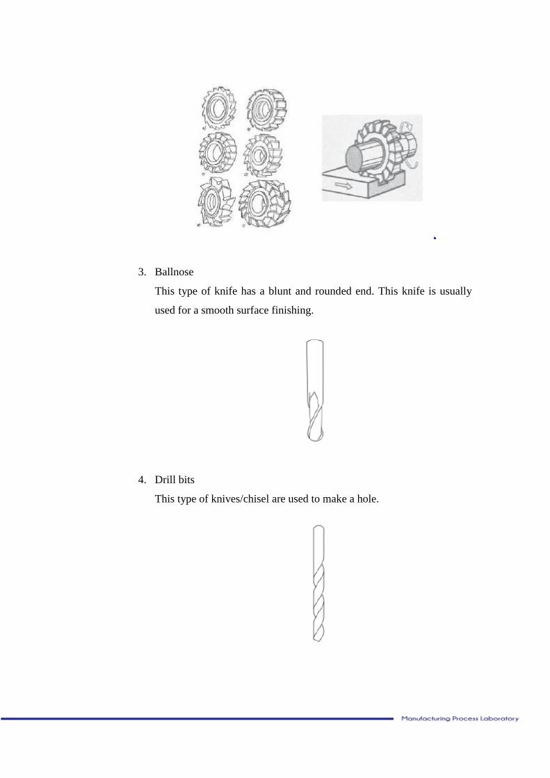
2. Slot Milling Cutter
This tool have a function to make grooves in the surface area of the
workpiece. This type of knife have some kind of custom adjusted types
thatare adjusted to the needs. Figure a and b show the knives type with
one sided groove slice eye, images c and d show two eyed groove
knife slice that are the face and the side , images e and f show two
eyed groove knife slice that are sides of the face and sides of the
crossed slice eyes.
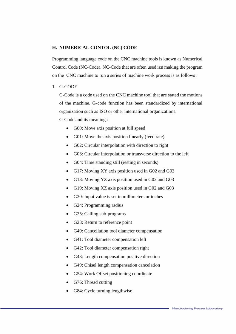
3. Ballnose
This type of knife has a blunt and rounded end. This knife is usually
used for a smooth surface finishing.
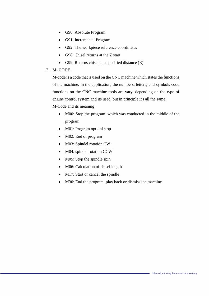
4. Drill bits
This type of knives/chisel are used to make a hole.
H. NUMERICAL CONTOL (NC) CODE
Programming language code on the CNC machine tools is known as Numerical
Control Code (NC-Code). NC-Code that are often used izn making the program
on the CNC machine to run a series of machine work process is as follows :
1. G-CODE
G-Code is a code used on the CNC machine tool that are stated the motions
of the machine. G-code function has been standardized by international
organization such as ISO or other international organizations.
G-Code and its meaning :
G00: Move axis position at full speed
G01: Move the axis position linearly (feed rate)
G02: Circular interpolation with direction to right
G03: Circular interpolation or transverse direction to the left
G04: Time standing still (resting in seconds)
G17: Moving XY axis position used in G02 and G03
G18: Moving YZ axis position used in G02 and G03
G19: Moving XZ axis position used in G02 and G03
G20: Input value is set in millimeters or inches
G24: Programming radius
G25: Calling sub-programs
G28: Return to reference point
G40: Cancellation tool diameter compensation
G41: Tool diameter compensation left
G42: Tool diameter compensation right
G43: Length compensation positive direction
G49: Chisel length compensation cancelation
G54: Work Offset positioning coordinate
G76: Thread cutting
G84: Cycle turning lengthwise
G90: Absolute Program
G91: Incremental Program
G92: The workpiece reference coordinates
G98: Chisel returns at the Z start
G99: Returns chisel at a specified distance (R)
2. M- CODE
M-code is a code that is used on the CNC machine which states the functions
of the machine. In the application, the numbers, letters, and symbols code
functions on the CNC machine tools are vary, depending on the type of
engine control system and its used, but in principle it's all the same.
M-Code and its meaning :
M00: Stop the program, which was conducted in the middle of the
program
M01: Program optionl stop
M02: End of program
M03: Spindel rotation CW
M04: spindel rotation CCW
M05: Stop the spindle spin
M06: Calculation of chisel length
M17: Start or cancel the spindle
M30: End the program, play back or dismiss the machine
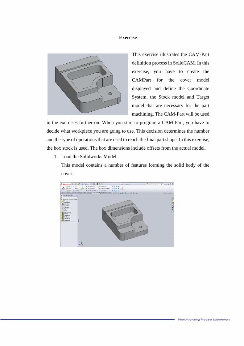
Exercise
This exercise illustrates the CAM-Part
definition process in SolidCAM. In this
exercise, you have to create the
CAMPart for the cover model
displayed and define the Coordinate
System, the Stock model and Target
model that are necessary for the part
machining. The CAM-Part will be used
in the exercises further on. When you start to program a CAM-Part, you have to
decide what workpiece you are going to use. This decision determines the number
and the type of operations that are used to reach the final part shape. In this exercise,
the box stock is used. The box dimensions include offsets from the actual model.
1. Load the Solidworks Model
This model contains a number of features forming the solid body of the
cover.
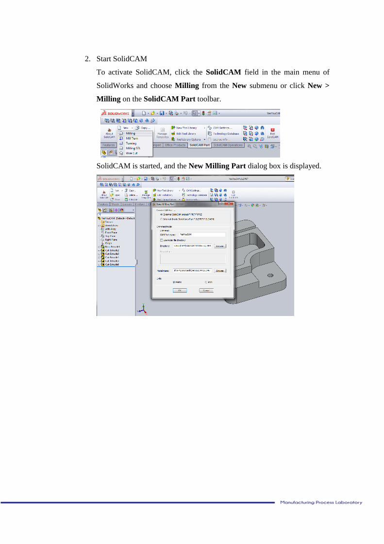
2. Start SolidCAM
To activate SolidCAM, click the SolidCAM field in the main menu of
SolidWorks and choose Milling from the New submenu or click New >
Milling on the SolidCAM Part toolbar.
SolidCAM is started, and the New Milling Part dialog box is displayed.
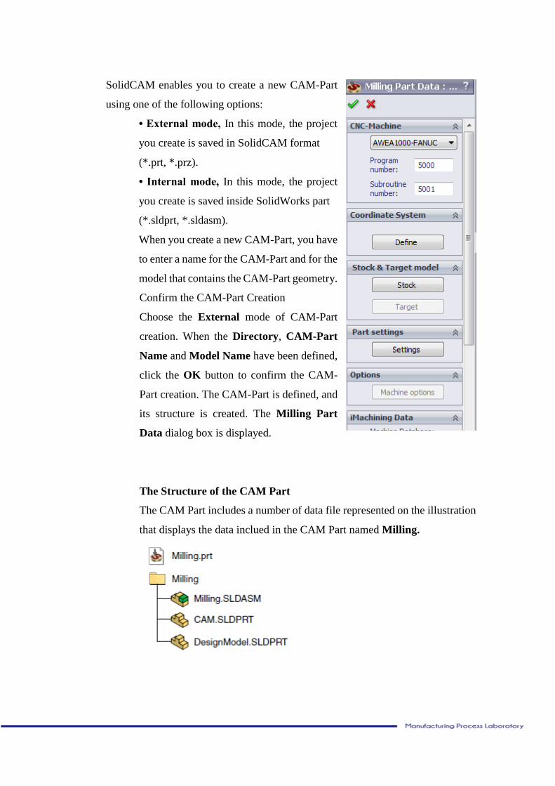
SolidCAM enables you to create a new CAM-Part
using one of the following options:
• External mode, In this mode, the project
you create is saved in SolidCAM format
(*.prt, *.prz).
• Internal mode, In this mode, the project
you create is saved inside SolidWorks part
(*.sldprt, *.sldasm).
When you create a new CAM-Part, you have
to enter a name for the CAM-Part and for the
model that contains the CAM-Part geometry.
Confirm the CAM-Part Creation
Choose the External mode of CAM-Part
creation. When the Directory, CAM-Part
Name and Model Name have been defined,
click the OK button to confirm the CAM-
Part creation. The CAM-Part is defined, and
its structure is created. The Milling Part
Data dialog box is displayed.
The Structure of the CAM Part
The CAM Part includes a number of data file represented on the illustration
that displays the data inclued in the CAM Part named Milling.
SolidCAM copies the original SolidWorks model to the Milling
subdirectory and creates a SolidWorks assembly that has the same name as
the CAM-Part (Milling.sldasm). There are two components in this
assembly:
DesignModel.sldprt – a copy of the SolidWorks model file.
CAM.sldprt – a file that contains SolidCAM Coordinate System
data and geometry data.
The SolidCAM CAM-Part uses the assembly environment of SolidWorks.
This enables you to create auxiliary geometries (i.e. sketches) without
making changes in the original design model. You can also insert some
additional components into the assembly file such as stock model,
CNCmachine table, clamping and other tooling elements.
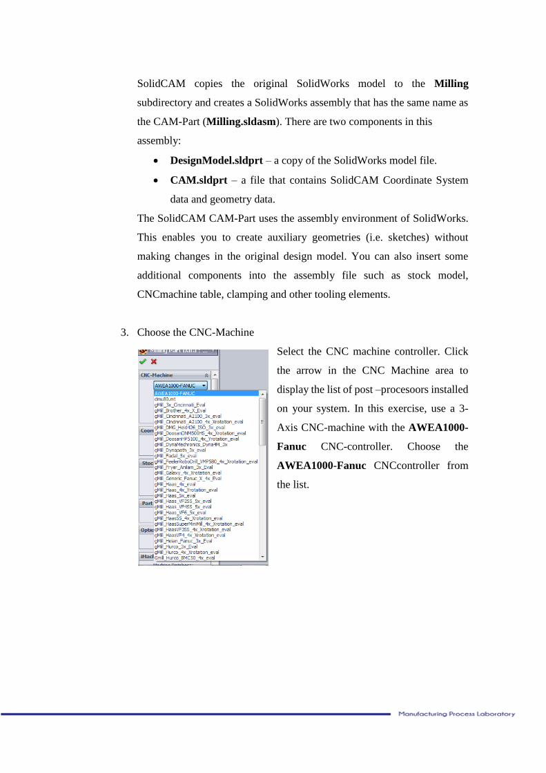
3. Choose the CNC-Machine
Select the CNC machine controller. Click
the arrow in the CNC Machine area to
display the list of post –procesoors installed
on your system. In this exercise, use a 3-
Axis CNC-machine with the AWEA1000-
Fanuc CNC-controller. Choose the
AWEA1000-Fanuc CNCcontroller from
the list.
4. Start the Coordinate System Definition
Click the define button in the coordinate system area
to define the machine coordinate system.
To complete the CAM-Part definition, you need to define the Machine
Coordinate System.
The Machine Coordinate System defines the origin for all machining
operations of the CAM-Part. It corresponds with the built-in controller
functions. You can define the Coordinate System origin position and axes
orientation by selecting model faces, vertices, edges, or SolidWorks
Coordinate Systems. The geometry for the machining can also be defined
directly on the solid model.
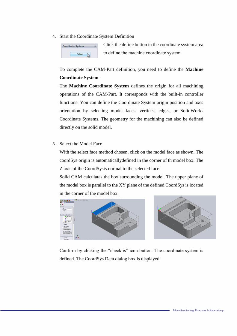
5. Select the Model Face
With the select face method chosen, click on the model face as shown. The
coordSys origin is automaticallydefined in the corner of th model box. The
Z axis of the CoordSysis normal to the selected face.
Solid CAM calculates the box surrounding the model. The upper plane of
the model box is parallel to the XY plane of the defined CoordSys is located
in the corner of the model box.
Confirm by clicking the “checklis” icon button. The coordinate system is
defined. The CoordSys Data dialog box is displayed.
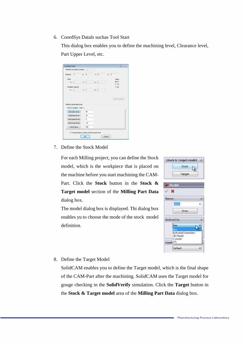
6. CoordSys Datals suchas Tool Start
This dialog box enables you to define the machining level, Clearance level,
Part Upper Level, etc.
7. Define the Stock Model
For each Milling project, you can define the Stock
model, which is the workpiece that is placed on
the machine before you start machining the CAM-
Part. Click the Stock button in the Stock &
Target model section of the Milling Part Data
dialog box.
The model dialog box is displayed. Thi dialog box
enables yu to choose the mode of the stock model
definition.
8. Define the Target Model
SolidCAM enables you to define the Target model, which is the final shape
of the CAM-Part after the machining. SolidCAM uses the Target model for
gouge checking in the SolidVerify simulation. Click the Target button in
the Stock & Target model area of the Milling Part Data dialog box.
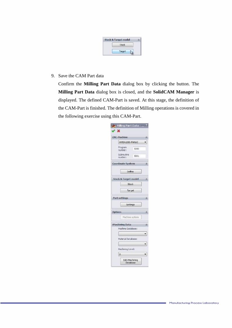
9. Save the CAM Part data
Confirm the Milling Part Data dialog box by clicking the button. The
Milling Part Data dialog box is closed, and the SolidCAM Manager is
displayed. The defined CAM-Part is saved. At this stage, the definition of
the CAM-Part is finished. The definition of Milling operations is covered in
the following exercise using this CAM-Part.
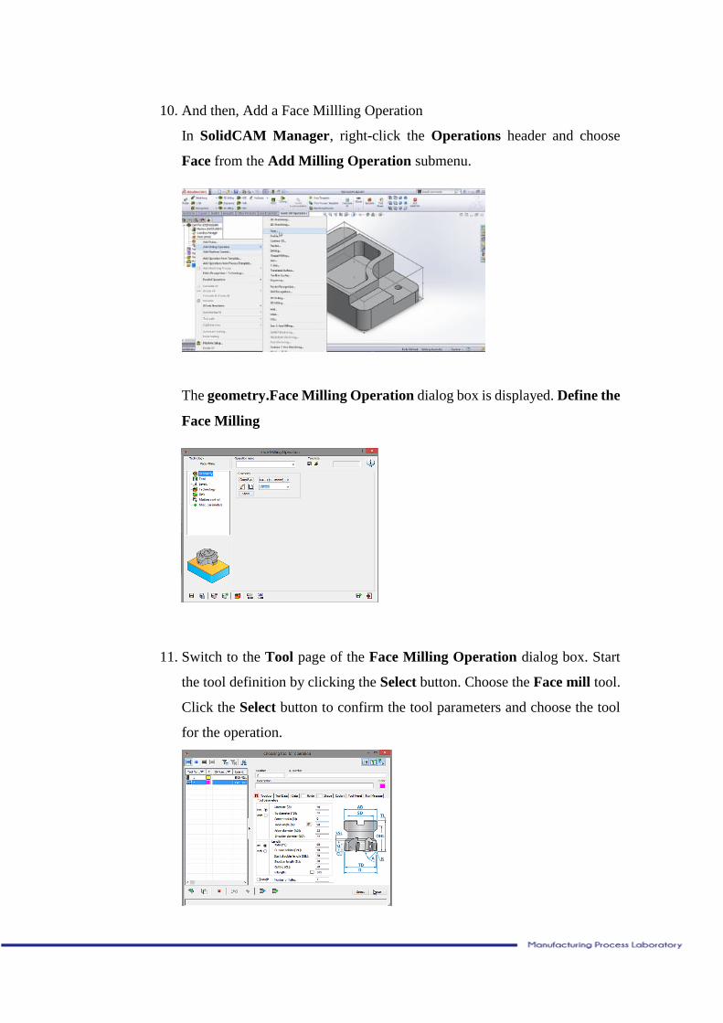
10. And then, Add a Face Millling Operation
In SolidCAM Manager, right-click the Operations header and choose
Face from the Add Milling Operation submenu.
The geometry.Face Milling Operation dialog box is displayed. Define the
Face Milling
11. Switch to the Tool page of the Face Milling Operation dialog box. Start
the tool definition by clicking the Select button. Choose the Face mill tool.
Click the Select button to confirm the tool parameters and choose the tool
for the operation.
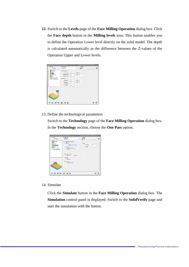
12. Switch to the Levels page of the Face Milling Operation dialog box. Click
the Face depth button in the Milling levels area. This button enables you
to define the Operation Lower level directly on the solid model. The depth
is calculated automatically as the difference between the Z-values of the
Operation Upper and Lower levels.
13. Define the technological parameters
Switch to the Technology page of the Face Milling Operation dialog box.
In the Technology section, choose the One Pass option.
14. Simulate
Click the Simulate button in the Face Milling Operation dialog box. The
Simulation control panel is displayed. Switch to the SolidVerify page and
start the simulation with the button.
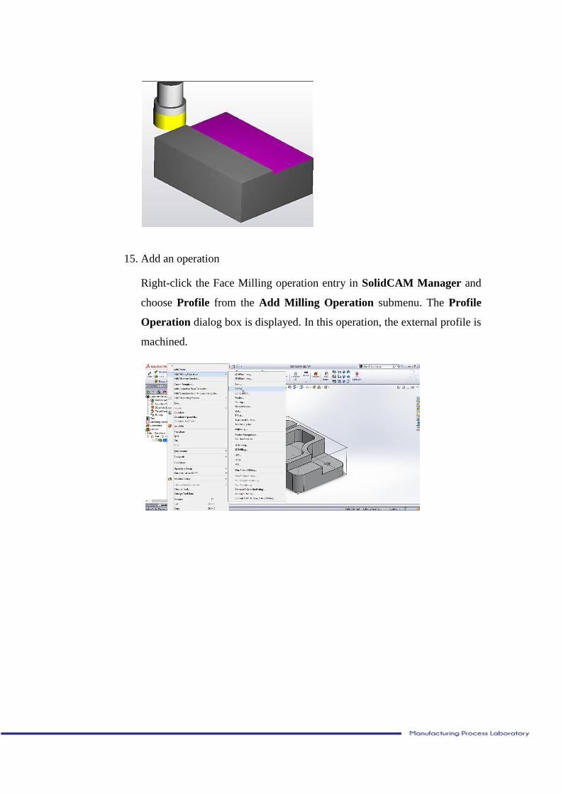
15. Add an operation
Right-click the Face Milling operation entry in SolidCAM Manager and
choose Profile from the Add Milling Operation submenu. The Profile
Operation dialog box is displayed. In this operation, the external profile is
machined.
Refrence:
Alavala, C.R., 2008. CAD/CAM: Concepts and Applications. India:
Prentice-Hall
Bodemyr, Emma., Vallin,Daniel., 2005. How Improve a
CAD/CAM/CNC-process. Adelaide: Lulea University of Technology.
Bralla,James., 2007. Handbook of Manufacturing Process. New York:
Industrial Press. Inc.
SolidCAM, 2013. Milling Training Course 2,5 D Module