Embed Size (px)
Citation preview
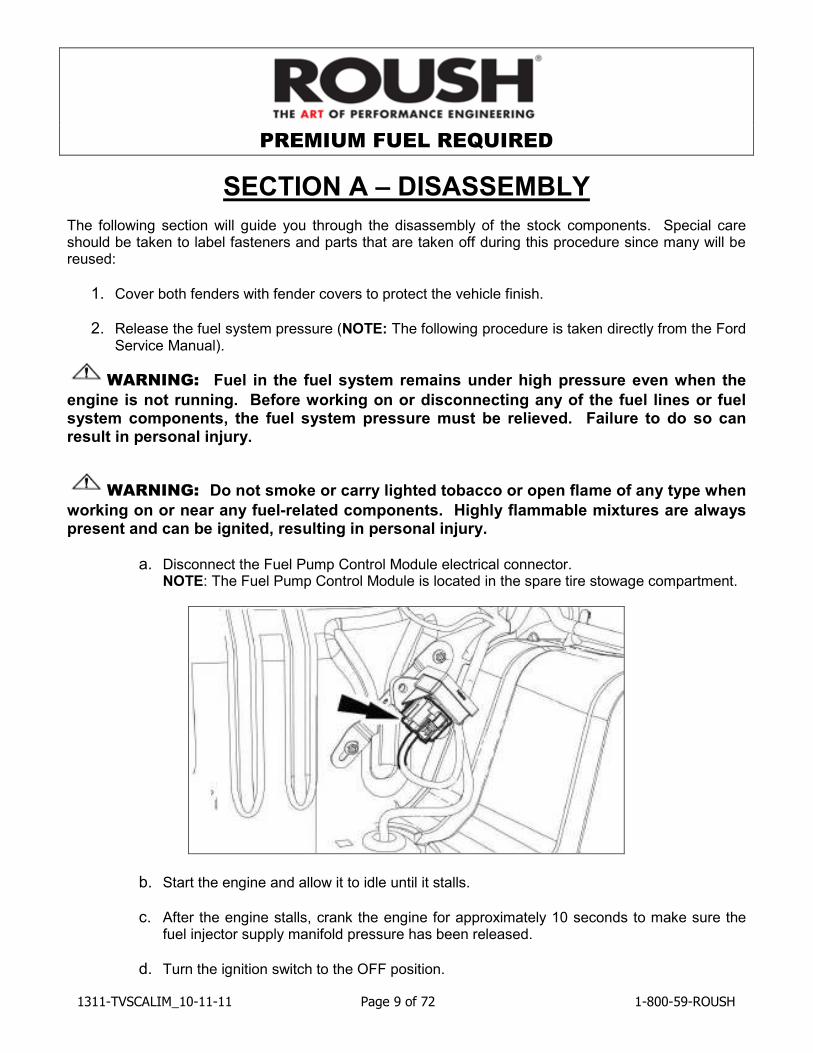
PREMIUM FUEL REQUIRED
1311-TVSCALIM_10-11-11 Page 1 of 72 1-800-59-ROUSH
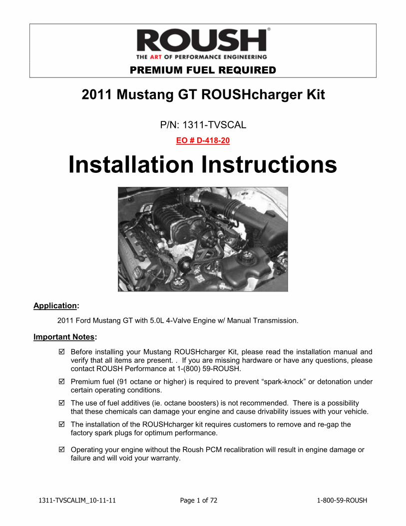
2011 Mustang GT ROUSHcharger Kit
P/N: 1311-TVSCAL
EO # D-418-20
Installation Instructions
Application:
2011 Ford Mustang GT with 5.0L 4-Valve Engine w/ Manual Transmission.
Important Notes:
� Before installing your Mustang ROUSHcharger Kit, please read the installation manual and verify that all items are present. . If you are missing hardware or have any questions, please contact ROUSH Performance at 1-(800) 59-ROUSH.
� Premium fuel (91 octane or higher) is required to prevent “spark-knock” or detonation under certain operating conditions.
� The use of fuel additives (ie. octane boosters) is not recommended. There is a possibility that these chemicals can damage your engine and cause drivability issues with your vehicle.
� The installation of the ROUSHcharger kit requires customers to remove and re-gap the factory spark plugs for optimum performance.
� Operating your engine without the Roush PCM recalibration will result in engine damage or
failure and will void your warranty.
PREMIUM FUEL REQUIRED
1311-TVSCALIM_10-11-11 Page 2 of 72 1-800-59-ROUSH
TABLE OF CONTENTS
PACKAGING LIST FOR 1311-TVSCAL SUPERCHARGER KIT................................................... 3
EQUIPMENT AND SUPPLIES REQUIRED ...................................................................................... 6
GLOSSARY OF TERMS ....................................................................................................................... 7
INFORMATION ABOUT THE SUPERCHARGER BYPASS OPERATION .................................. 7
LIMIT OF LIABILITY STATEMENT ..................................................................................................... 8
SAFETY PRECAUTIONS ..................................................................................................................... 8
SECTION A – DISASSEMBLY ............................................................................................................ 9
SECTION B – MODIFICATIONS....................................................................................................... 19
Airbox Modification ........................................................................................................................... 19 Brake Booster Hose Modification................................................................................................... 20 Front Cover Modification ................................................................................................................. 21 TPS/ETC Wiring ............................................................................................................................... 25 Canister Purge Valve Wiring........................................................................................................... 27 Intercooler Pump Wiring .................................................................................................................. 29 Air Charge Temperature (ACT) Wiring ......................................................................................... 31 Mass Air Flow (MAF) Wiring ........................................................................................................... 33 Knock Sensor Orientation Adjustment .......................................................................................... 34 Changing the Factory Spark Plugs for Optimum Performance................................................. 34
SECTION C – SUBASSEMBLY......................................................................................................... 35
Intercooler Low Temperature Radiator (LTR).............................................................................. 35 Intake Manifold Build Up ................................................................................................................. 38 Throttle Body Spacer Assembly..................................................................................................... 39 Fuel Rail Assembly........................................................................................................................... 41
SECTION D – INSTALLATION .......................................................................................................... 42
Intercooler Reservoir Mounting ...................................................................................................... 42 Intercooler Radiator Assembly Mounting...................................................................................... 43 Electric Water Pump, Mounting Bracket and Hoses................................................................... 44 Induction Resonance Tube Delete Grommet............................................................................... 49 Intake Manifold and Supercharger Installation ............................................................................ 50 FEAD Assembly................................................................................................................................ 56 Coolant Hoses................................................................................................................................... 61 Air Induction System ........................................................................................................................ 64 Final Assembly.................................................................................................................................. 67
PREMIUM FUEL REQUIRED
1311-TVSCALIM_10-11-11 Page 3 of 72 1-800-59-ROUSH
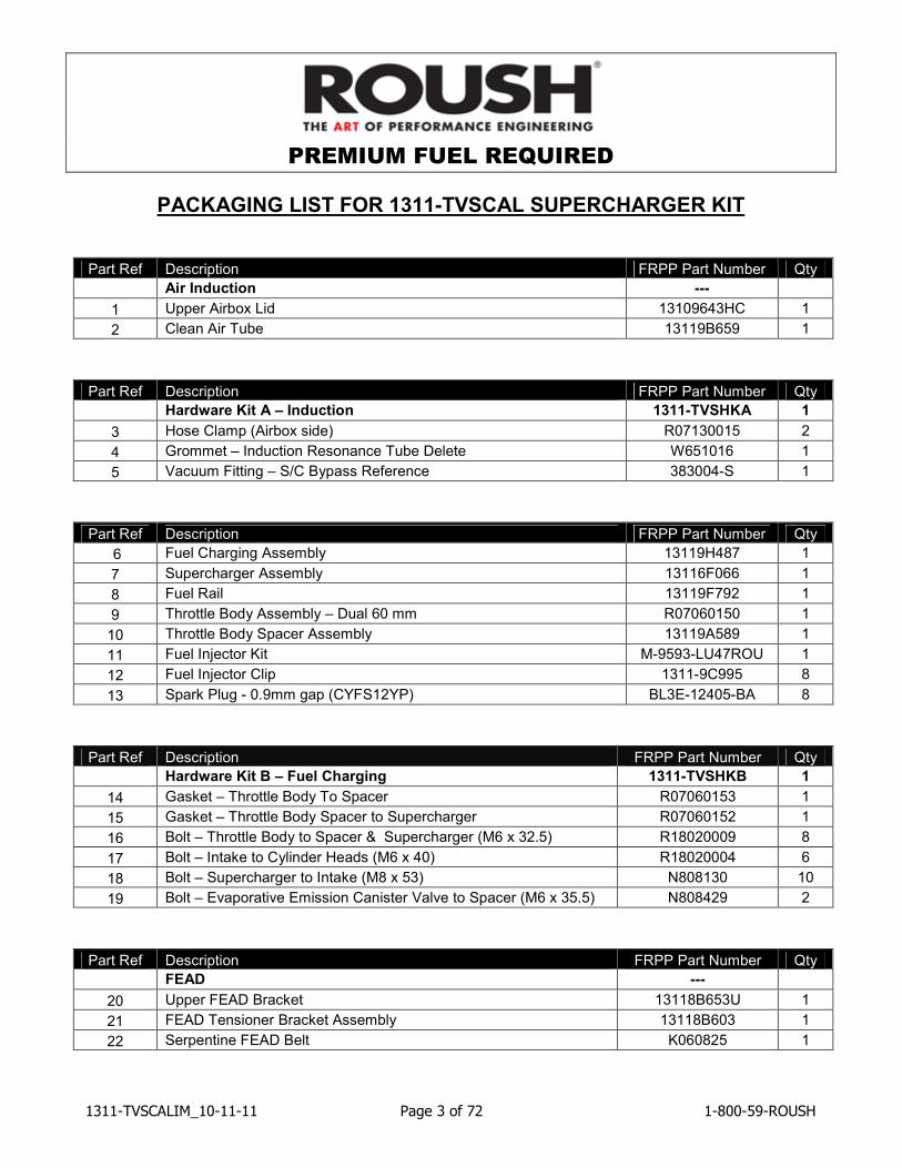
PACKAGING LIST FOR 1311-TVSCAL SUPERCHARGER KIT
Part Ref Description FRPP Part Number Qty
Air Induction ---
1 Upper Airbox Lid 13109643HC 1
2 Clean Air Tube 13119B659 1
Part Ref Description FRPP Part Number Qty
Hardware Kit A – Induction 1311-TVSHKA 1
3 Hose Clamp (Airbox side) R07130015 2
4 Grommet – Induction Resonance Tube Delete W651016 1
5 Vacuum Fitting – S/C Bypass Reference 383004-S 1
Part Ref Description FRPP Part Number Qty
6 Fuel Charging Assembly 13119H487 1
7 Supercharger Assembly 13116F066 1
8 Fuel Rail 13119F792 1
9 Throttle Body Assembly – Dual 60 mm R07060150 1
10 Throttle Body Spacer Assembly 13119A589 1
11 Fuel Injector Kit M-9593-LU47ROU 1
12 Fuel Injector Clip 1311-9C995 8
13 Spark Plug - 0.9mm gap (CYFS12YP) BL3E-12405-BA 8
Part Ref Description FRPP Part Number Qty
Hardware Kit B – Fuel Charging 1311-TVSHKB 1
14 Gasket – Throttle Body To Spacer R07060153 1
15 Gasket – Throttle Body Spacer to Supercharger R07060152 1
16 Bolt – Throttle Body to Spacer & Supercharger (M6 x 32.5) R18020009 8
17 Bolt – Intake to Cylinder Heads (M6 x 40) R18020004 6
18 Bolt – Supercharger to Intake (M8 x 53) N808130 10
19 Bolt – Evaporative Emission Canister Valve to Spacer (M6 x 35.5) N808429 2
Part Ref Description FRPP Part Number Qty
FEAD ---
20 Upper FEAD Bracket 13118B653U 1
21 FEAD Tensioner Bracket Assembly 13118B603 1
22 Serpentine FEAD Belt K060825 1
PREMIUM FUEL REQUIRED
1311-TVSCALIM_10-11-11 Page 4 of 72 1-800-59-ROUSH
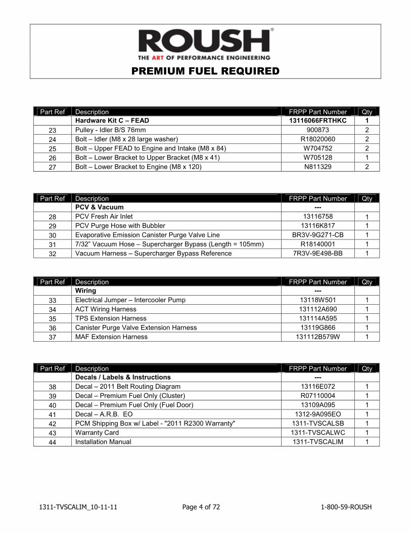
Part Ref Description FRPP Part Number Qty
Hardware Kit C – FEAD 13116066FRTHKC 1
23 Pulley - Idler B/S 76mm 900873 2
24 Bolt – Idler (M8 x 28 large washer) R18020060 2
25 Bolt – Upper FEAD to Engine and Intake (M8 x 84) W704752 2
26 Bolt – Lower Bracket to Upper Bracket (M8 x 41) W705128 1
27 Bolt – Lower Bracket to Engine (M8 x 120) N811329 2
Part Ref Description FRPP Part Number Qty
PCV & Vacuum ---
28 PCV Fresh Air Inlet 13116758 1
29 PCV Purge Hose with Bubbler 13116K817 1
30 Evaporative Emission Canister Purge Valve Line BR3V-9G271-CB 1
31 7/32” Vacuum Hose – Supercharger Bypass (Length = 105mm) R18140001 1
32 Vacuum Harness – Supercharger Bypass Reference 7R3V-9E498-BB 1
Part Ref Description FRPP Part Number Qty
Wiring ---
33 Electrical Jumper – Intercooler Pump 13118W501 1
34 ACT Wiring Harness 131112A690 1
35 TPS Extension Harness 131114A595 1
36 Canister Purge Valve Extension Harness 13119G866 1
37 MAF Extension Harness 131112B579W 1
Part Ref Description FRPP Part Number Qty
Decals / Labels & Instructions ---
38 Decal – 2011 Belt Routing Diagram 13116E072 1
39 Decal – Premium Fuel Only (Cluster) R07110004 1
40 Decal – Premium Fuel Only (Fuel Door) 13109A095 1
41 Decal – A.R.B. EO 1312-9A095EO 1
42 PCM Shipping Box w/ Label - "2011 R2300 Warranty" 1311-TVSCALSB 1
43 Warranty Card 1311-TVSCALWC 1
44 Installation Manual 1311-TVSCALIM 1
PREMIUM FUEL REQUIRED
1311-TVSCALIM_10-11-11 Page 5 of 72 1-800-59-ROUSH
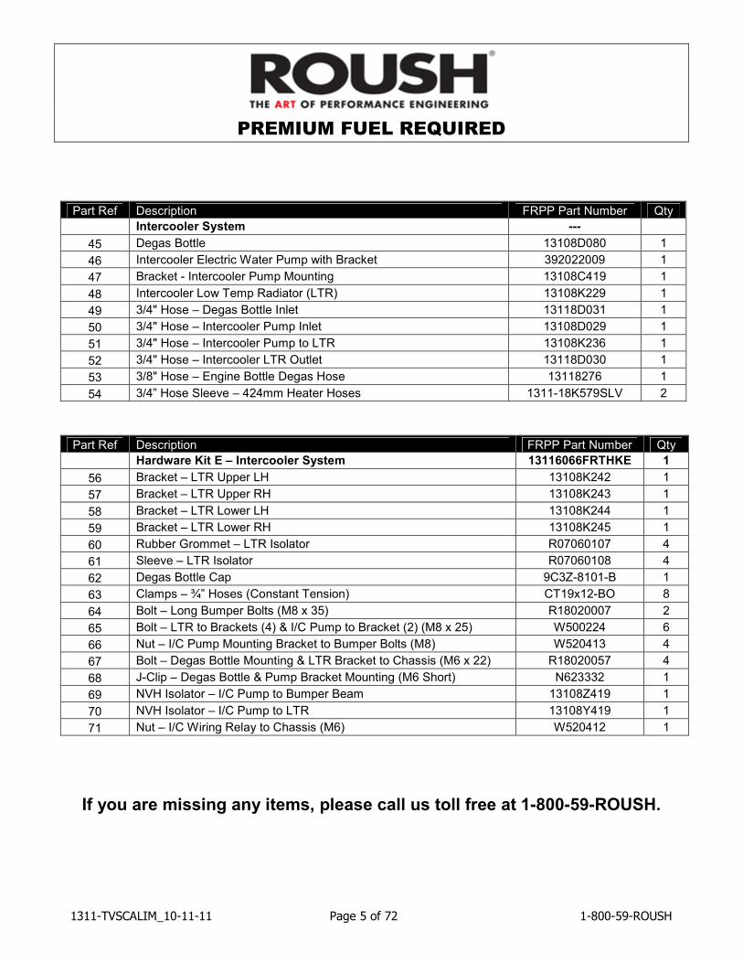
Part Ref Description FRPP Part Number Qty
Intercooler System ---
45 Degas Bottle 13108D080 1
46 Intercooler Electric Water Pump with Bracket 392022009 1
47 Bracket - Intercooler Pump Mounting 13108C419 1
48 Intercooler Low Temp Radiator (LTR) 13108K229 1
49 3/4" Hose – Degas Bottle Inlet 13118D031 1
50 3/4" Hose – Intercooler Pump Inlet 13108D029 1
51 3/4" Hose – Intercooler Pump to LTR 13108K236 1
52 3/4" Hose – Intercooler LTR Outlet 13118D030 1
53 3/8" Hose – Engine Bottle Degas Hose 13118276 1
54 3/4” Hose Sleeve – 424mm Heater Hoses 1311-18K579SLV 2
Part Ref Description FRPP Part Number Qty
Hardware Kit E – Intercooler System 13116066FRTHKE 1
56 Bracket – LTR Upper LH 13108K242 1
57 Bracket – LTR Upper RH 13108K243 1
58 Bracket – LTR Lower LH 13108K244 1
59 Bracket – LTR Lower RH 13108K245 1
60 Rubber Grommet – LTR Isolator R07060107 4
61 Sleeve – LTR Isolator R07060108 4
62 Degas Bottle Cap 9C3Z-8101-B 1
63 Clamps – ¾” Hoses (Constant Tension) CT19x12-BO 8
64 Bolt – Long Bumper Bolts (M8 x 35) R18020007 2
65 Bolt – LTR to Brackets (4) & I/C Pump to Bracket (2) (M8 x 25) W500224 6
66 Nut – I/C Pump Mounting Bracket to Bumper Bolts (M8) W520413 4
67 Bolt – Degas Bottle Mounting & LTR Bracket to Chassis (M6 x 22) R18020057 4
68 J-Clip – Degas Bottle & Pump Bracket Mounting (M6 Short) N623332 1
69 NVH Isolator – I/C Pump to Bumper Beam 13108Z419 1
70 NVH Isolator – I/C Pump to LTR 13108Y419 1
71 Nut – I/C Wiring Relay to Chassis (M6) W520412 1
If you are missing any items, please call us toll free at 1-800-59-ROUSH.
PREMIUM FUEL REQUIRED
1311-TVSCALIM_10-11-11 Page 6 of 72 1-800-59-ROUSH
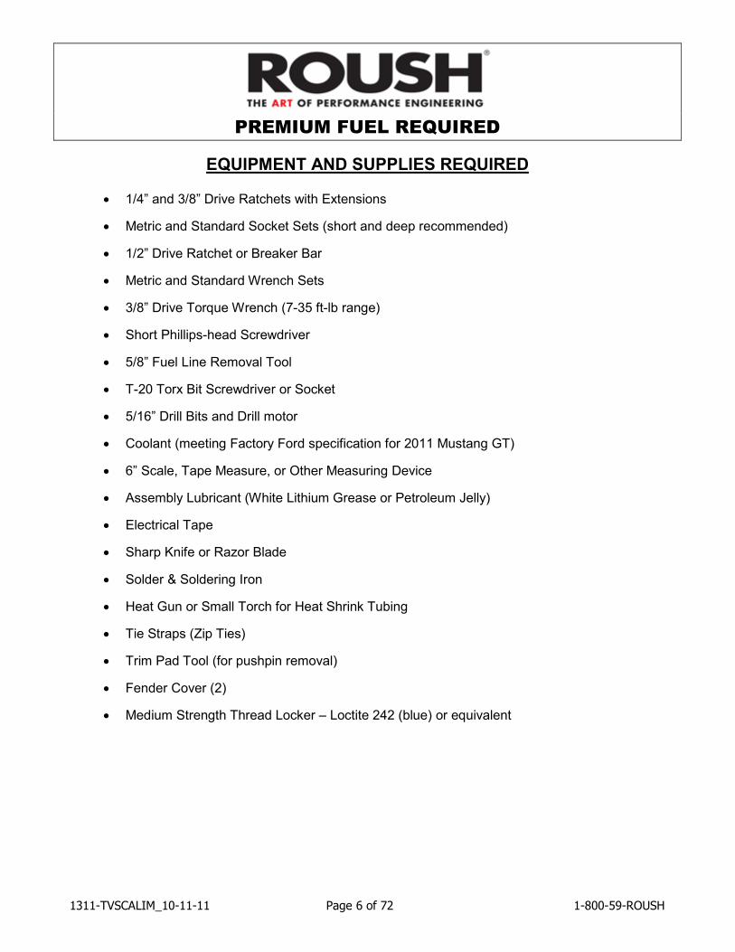
EQUIPMENT AND SUPPLIES REQUIRED
• 1/4” and 3/8” Drive Ratchets with Extensions
• Metric and Standard Socket Sets (short and deep recommended)
• 1/2” Drive Ratchet or Breaker Bar
• Metric and Standard Wrench Sets
• 3/8” Drive Torque Wrench (7-35 ft-lb range)
• Short Phillips-head Screwdriver
• 5/8” Fuel Line Removal Tool
• T-20 Torx Bit Screwdriver or Socket
• 5/16” Drill Bits and Drill motor
• Coolant (meeting Factory Ford specification for 2011 Mustang GT)
• 6” Scale, Tape Measure, or Other Measuring Device
• Assembly Lubricant (White Lithium Grease or Petroleum Jelly)
• Electrical Tape
• Sharp Knife or Razor Blade
• Solder & Soldering Iron
• Heat Gun or Small Torch for Heat Shrink Tubing
• Tie Straps (Zip Ties)
• Trim Pad Tool (for pushpin removal)
• Fender Cover (2)
• Medium Strength Thread Locker – Loctite 242 (blue) or equivalent
PREMIUM FUEL REQUIRED
1311-TVSCALIM_10-11-11 Page 7 of 72 1-800-59-ROUSH
GLOSSARY OF TERMS ACT Air Charge Temperature Sensor (From the factory, this function is integrated into the
MAF sensor. With this kit, a separate ACT sensor is installed into the intake manifold)
ETC Electronic Throttle Control MAFS Mass Air Flow Sensor PCM Powertrain Control Module (a.k.a. ECM, ECU, PCU, EEC) PCV Positive Crankcase Ventilation TPS Throttle Position Sensor VMV Vapor Management Valve (aka Canister Purge Valve) Breakout Point A place in an electrical harness where the wiring for an individual component leaves
(breaks out of) the main harness to attach to an individual component.
INFORMATION ABOUT THE SUPERCHARGER BYPASS OPERATION
There is a great deal of misinformation about the function of supercharger bypass systems. The supercharger is a positive-displacement pump; that is, so long as it is rotating, it is always pumping air. During low demand or high vacuum operation (i.e. idle, deceleration, and light throttle cruise), the pumping action is undesirable as it creates unwanted heat and noise. The bypass circuit, when open, prevents any pressure buildup across the supercharger and allows air to circulate through the rotors, allowing the supercharger to “idle” freely during these conditions. This results in reduced noise, and by reducing heat buildup in the intake, significantly improves street and strip performance. As throttle demand increases, the bypass circuit is closed, resulting in full performance from the supercharger. The bypass circuit is never used to limit or control boost during full-throttle operation and defeating or altering the bypass function will not result in improved performance in any condition, and will result in poor drivability.
PREMIUM FUEL REQUIRED
1311-TVSCALIM_10-11-11 Page 8 of 72 1-800-59-ROUSH
LIMIT OF LIABILITY STATEMENT The information contained in this publication was accurate and in effect at the time the publication was approved for printing and is subject to change without notice or liability. Ford Racing Performance Parts reserves the right to revise the information presented herein or to discontinue the production of parts described at any time.
SAFETY PRECAUTIONS
STOP! CAREFULLY READ THE IMPORTANT SAFETY PRECAUTIONS AND WARNINGS
BEFORE PROCEEDING WITH THE INSTALLATION! Appropriate disassembly, assembly methods and procedures are essential to ensure the personal safety of the individual performing the kit installation. Improper installation due to the failure to correctly follow these instructions could cause personal injury or death. Read each step of the installation manual carefully before starting the installation.
!!!! Always wear safety glasses for eye protection.
!!!! Place the ignition switch in the OFF position.
!!!! Always apply the parking brake when working on the vehicle.
!!!! Block the front and rear tire surfaces to prevent unexpected vehicle movement.
!!!! Operate the engine only in well-ventilated areas to avoid exposure to carbon monoxide.
!!!! Do not smoke or use flammable items near or around the fuel system.
!!!! Use chemicals and cleaners only in well-ventilated areas.
!!!! Batteries can produce explosive hydrogen gas which can cause personal injury. Do not
allow flames, sparks or flammable sources to come near the battery.
!!!! Keep hands and any other objects away from the radiator fan blades.
!!!! Keep yourself and your clothing away from moving parts when the engine is running.
!!!! Do not wear loose clothing or jewelry that can be caught in rotating or moving parts.
PREMIUM FUEL REQUIRED
1311-TVSCALIM_10-11-11 Page 9 of 72 1-800-59-ROUSH
SECTION A – DISASSEMBLY
The following section will guide you through the disassembly of the stock components. Special care should be taken to label fasteners and parts that are taken off during this procedure since many will be reused:
1. Cover both fenders with fender covers to protect the vehicle finish.
2. Release the fuel system pressure (NOTE: The following procedure is taken directly from the Ford Service Manual).
WARNING: Fuel in the fuel system remains under high pressure even when the
engine is not running. Before working on or disconnecting any of the fuel lines or fuel system components, the fuel system pressure must be relieved. Failure to do so can result in personal injury.
WARNING: Do not smoke or carry lighted tobacco or open flame of any type when
working on or near any fuel-related components. Highly flammable mixtures are always present and can be ignited, resulting in personal injury.
a. Disconnect the Fuel Pump Control Module electrical connector. NOTE: The Fuel Pump Control Module is located in the spare tire stowage compartment.
b. Start the engine and allow it to idle until it stalls.
c. After the engine stalls, crank the engine for approximately 10 seconds to make sure the fuel injector supply manifold pressure has been released.
d. Turn the ignition switch to the OFF position.
PREMIUM FUEL REQUIRED
1311-TVSCALIM_10-11-11 Page 10 of 72 1-800-59-ROUSH
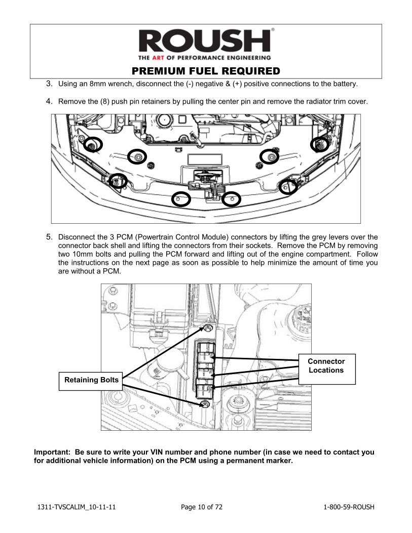
3. Using an 8mm wrench, disconnect the (-) negative & (+) positive connections to the battery.
4. Remove the (8) push pin retainers by pulling the center pin and remove the radiator trim cover.
5. Disconnect the 3 PCM (Powertrain Control Module) connectors by lifting the grey levers over the connector back shell and lifting the connectors from their sockets. Remove the PCM by removing two 10mm bolts and pulling the PCM forward and lifting out of the engine compartment. Follow the instructions on the next page as soon as possible to help minimize the amount of time you are without a PCM.
Important: Be sure to write your VIN number and phone number (in case we need to contact you for additional vehicle information) on the PCM using a permanent marker.
Connector
Locations
Retaining Bolts
PREMIUM FUEL REQUIRED
1311-TVSCALIM_10-11-11 Page 11 of 72 1-800-59-ROUSH
INSTRUCTIONS FOR RETURNING THE PCM TO ROUSH FOR CALIBRATION
Outlined below are the instructions for returning your stock powertrain control module (PCM) to Roush Performance Products so we can install our calibration to make the engine run properly with the new components. Please complete the “Warranty Registration Card” and include it, along with the PCM, in the prepaid shipping box. The prepaid shipping box is set-up for next day delivery to us. Once we receive your PCM, we will reprogram and return it back to you the same day for next-day delivery. Operating your engine without our calibration will result in engine damage or failure and will void all warranty.
Note: It is important to reinstall the PCM in the vehicle it came from to prevent setting a trouble code and having to relearn the anti-theft code which can only be performed using specialized Ford Service Bay tools.
• If you haven’t already done so, write your vehicle identification number (VIN) and phone number on the PCM using a permanent marker.
• Remove the bubble wrap from inside the supplied shipping box and wrap it around the PCM to help prevent it from being damaged during shipping.
• Place the wrapped PCM in the shipping box (13106066M90SB).
• Complete the “Warranty Registration Card” (131019A505) and include it in the shipping box along with the PCM.
• Fill in your name and address in the FROM area of the shipping label that is located inside the box. Follow the instructions on the box for sealing it shut.
• Peel the right label off and attach to the box where indicated.
• Retain the left side label for your records.
• Schedule a FEDEX Package Pick-up by calling 1-800-463-3339 and select OPTION 0 to speak directly to an agent. DO NOT use the automated option to schedule a pick up.
• Inform the agent you have a Prepaid FEDEX billable stamp package and you need a pick-up.
• If there are any issues with the shipping box we supply and you want to ship the PCM to us another way, the address for the PCM re-flash only is: Roush Powertrain Development, Building 57 – attn: PCM Flash, 777 Republic Drive, Allen Park, MI 48101
Customer Name: ________________________ Contact Number: ________________________ VIN: ________________________
2011 5.0L 4V Mustang TVS2300 ROUSHCharger Kit – Manual Transmission
PREMIUM FUEL REQUIRED
1311-TVSCALIM_10-11-11 Page 12 of 72 1-800-59-ROUSH
6. Raise the front of the vehicle using the Ford recommended lifting points and place onto safety stands. With the tires lifted off of the ground, remove the front wheels. Remove the (3) forward Phillips-head screws from each front wheel liner. Using a Phillips-head screwdriver, turn the (5) inner fender push pins ¼ turn to release the centers. Remove the pushpins and then remove the forward inner fenders.
7. Remove the (3) lower close-out to radiator support screws (7mm socket). Remove the (2) upper bumper cover screws near the headlights (10mm socket). Remove the (4) front fender to bumper cover nuts inside the forward wheel well (10mm socket). Reach inside the front wheel wells and unplug the front turn signals. Lift the front bumper cover slightly and pull partially off of the vehicle. Unplug the fog lights and set the front bumper cover aside.
8. Remove the (4) push pins that retain the impact absorber to the front bumper beam and set the absorber aside.
9. Carefully remove the radiator / cooling module side shields that are mounted to the left & right hand side of the A/C Condenser. (See Appendix A) Note: The LH shield engages the air inlet system.
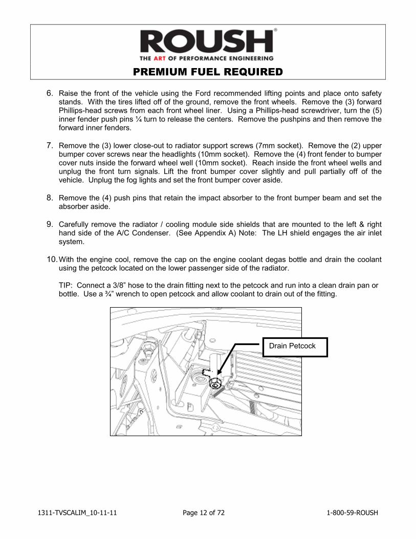
10. With the engine cool, remove the cap on the engine coolant degas bottle and drain the coolant using the petcock located on the lower passenger side of the radiator.
TIP: Connect a 3/8” hose to the drain fitting next to the petcock and run into a clean drain pan or
bottle. Use a ¾” wrench to open petcock and allow coolant to drain out of the fitting.
Drain Petcock
PREMIUM FUEL REQUIRED
1311-TVSCALIM_10-11-11 Page 13 of 72 1-800-59-ROUSH
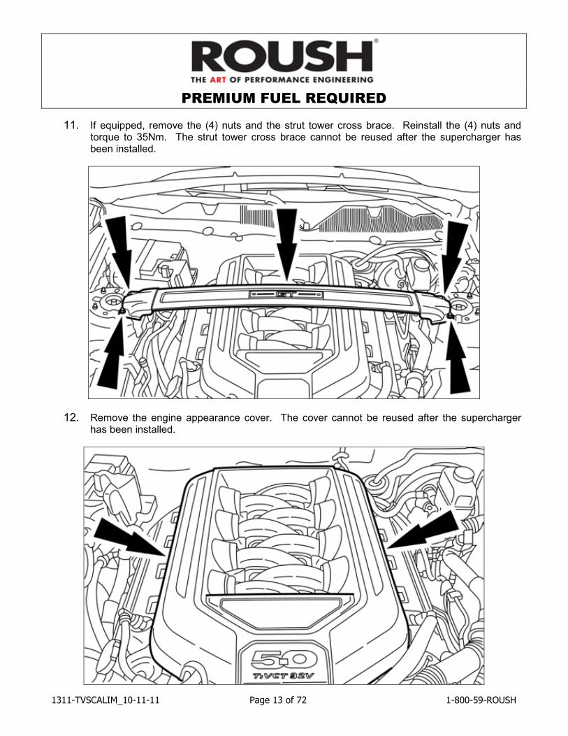
11. If equipped, remove the (4) nuts and the strut tower cross brace. Reinstall the (4) nuts and torque to 35Nm. The strut tower cross brace cannot be reused after the supercharger has been installed.
12. Remove the engine appearance cover. The cover cannot be reused after the supercharger has been installed.
PREMIUM FUEL REQUIRED
1311-TVSCALIM_10-11-11 Page 14 of 72 1-800-59-ROUSH
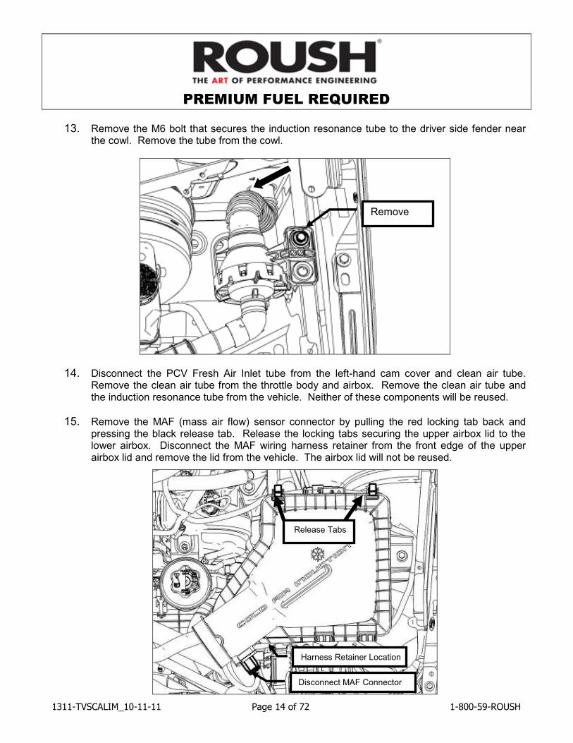
13. Remove the M6 bolt that secures the induction resonance tube to the driver side fender near the cowl. Remove the tube from the cowl.
14. Disconnect the PCV Fresh Air Inlet tube from the left-hand cam cover and clean air tube. Remove the clean air tube from the throttle body and airbox. Remove the clean air tube and the induction resonance tube from the vehicle. Neither of these components will be reused.
15. Remove the MAF (mass air flow) sensor connector by pulling the red locking tab back and pressing the black release tab. Release the locking tabs securing the upper airbox lid to the lower airbox. Disconnect the MAF wiring harness retainer from the front edge of the upper airbox lid and remove the lid from the vehicle. The airbox lid will not be reused.
Release Tabs
Disconnect MAF Connector
Remove
Harness Retainer Location
PREMIUM FUEL REQUIRED
1311-TVSCALIM_10-11-11 Page 15 of 72 1-800-59-ROUSH
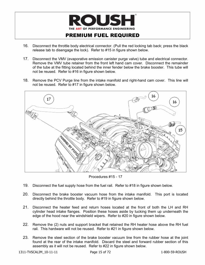
16. Disconnect the throttle body electrical connector. (Pull the red locking tab back; press the black release tab to disengage the lock). Refer to #15 in figure shown below.
17. Disconnect the VMV (evaporative emission canister purge valve) tube and electrical connector. Remove the VMV tube retainer from the front left hand cam cover. Disconnect the remainder of the tube at the fitting located behind the inner fender below the brake booster. This tube will not be reused. Refer to #16 in figure shown below.
18. Remove the PCV Purge line from the intake manifold and right-hand cam cover. This line will not be reused. Refer to #17 in figure shown below.
Procedures #15 - 17
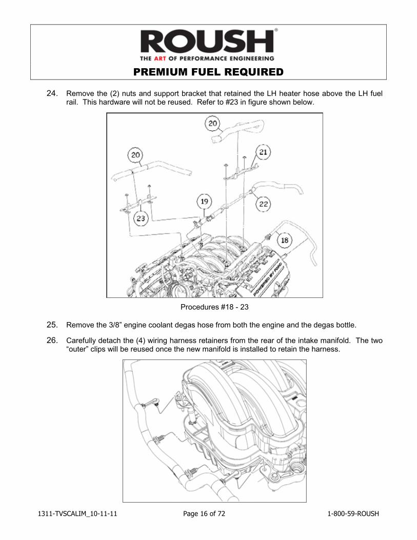
19. Disconnect the fuel supply hose from the fuel rail. Refer to #18 in figure shown below.
20. Disconnect the brake booster vacuum hose from the intake manifold. This port is located directly behind the throttle body. Refer to #19 in figure shown below.
21. Disconnect the heater feed and return hoses located at the front of both the LH and RH cylinder head intake flanges. Position these hoses aside by tucking them up underneath the edge of the hood near the windshield wipers. Refer to #20 in figure shown below.
22. Remove the (2) nuts and support bracket that retained the RH heater hose above the RH fuel rail. This hardware will not be reused. Refer to #21 in figure shown below.
23. Remove the steel section of the brake booster vacuum line from the rubber hose at the joint found at the rear of the intake manifold. Discard the steel and forward rubber section of this assembly as it will not be reused. Refer to #22 in figure shown below.
PREMIUM FUEL REQUIRED
1311-TVSCALIM_10-11-11 Page 16 of 72 1-800-59-ROUSH
24. Remove the (2) nuts and support bracket that retained the LH heater hose above the LH fuel rail. This hardware will not be reused. Refer to #23 in figure shown below.
Procedures #18 - 23
25. Remove the 3/8” engine coolant degas hose from both the engine and the degas bottle.
26. Carefully detach the (4) wiring harness retainers from the rear of the intake manifold. The two “outer” clips will be reused once the new manifold is installed to retain the harness.
PREMIUM FUEL REQUIRED
1311-TVSCALIM_10-11-11 Page 17 of 72 1-800-59-ROUSH
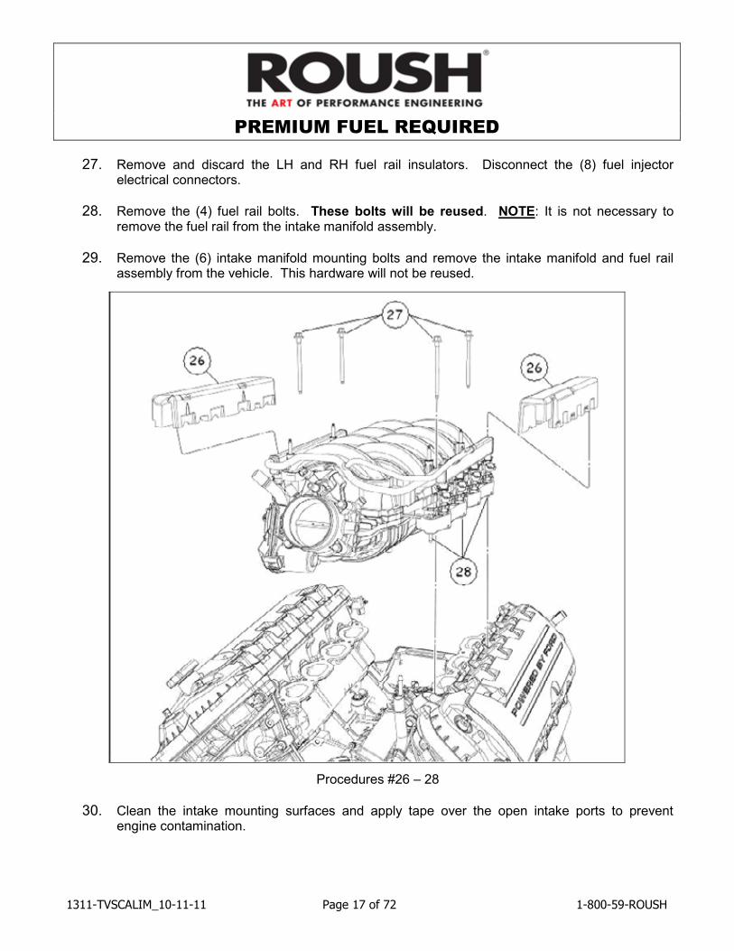
27. Remove and discard the LH and RH fuel rail insulators. Disconnect the (8) fuel injector electrical connectors.
28. Remove the (4) fuel rail bolts. These bolts will be reused. NOTE: It is not necessary to remove the fuel rail from the intake manifold assembly.
29. Remove the (6) intake manifold mounting bolts and remove the intake manifold and fuel rail assembly from the vehicle. This hardware will not be reused.
Procedures #26 – 28
30. Clean the intake mounting surfaces and apply tape over the open intake ports to prevent engine contamination.
PREMIUM FUEL REQUIRED
1311-TVSCALIM_10-11-11 Page 18 of 72 1-800-59-ROUSH
31. Remove the engine coolant degas bottle.
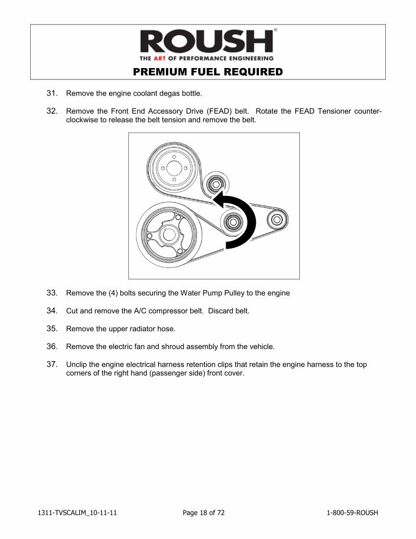
32. Remove the Front End Accessory Drive (FEAD) belt. Rotate the FEAD Tensioner counter-clockwise to release the belt tension and remove the belt.
33. Remove the (4) bolts securing the Water Pump Pulley to the engine
34. Cut and remove the A/C compressor belt. Discard belt.
35. Remove the upper radiator hose.
36. Remove the electric fan and shroud assembly from the vehicle.
37. Unclip the engine electrical harness retention clips that retain the engine harness to the top corners of the right hand (passenger side) front cover.

PREMIUM FUEL REQUIRED
1311-TVSCALIM_10-11-11 Page 19 of 72 1-800-59-ROUSH
SECTION B – MODIFICATIONS
The following section will guide you through the required modifications of existing components and build up of the assemblies used to complete the installation. With the exception of the wiring modifications and intercooler pump bracket mounting, all of this work can be performed away from the vehicle.
Airbox Modification
1. Remove the MAF sensor from the stock airbox cover and install into the new upper airbox lid (13109643HC) using the two factory fasteners. Torque screws to 1.8 – 2.2 Nm.
2. In order for the new airbox lid to be secured to the lower airbox tray properly, the inboard retaining clip needs to be modified. Remove the inboard clip from the tray and use a saw or grinder to remove part of the clip as shown. Deburr all sharp edges.
Modify this clip
PREMIUM FUEL REQUIRED
1311-TVSCALIM_10-11-11 Page 20 of 72 1-800-59-ROUSH
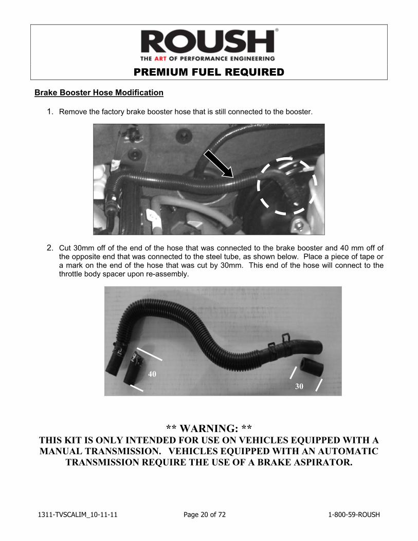
Brake Booster Hose Modification
1. Remove the factory brake booster hose that is still connected to the booster.
2. Cut 30mm off of the end of the hose that was connected to the brake booster and 40 mm off of the opposite end that was connected to the steel tube, as shown below. Place a piece of tape or a mark on the end of the hose that was cut by 30mm. This end of the hose will connect to the throttle body spacer upon re-assembly.
** WARNING: ** THIS KIT IS ONLY INTENDED FOR USE ON VEHICLES EQUIPPED WITH A
MANUAL TRANSMISSION. VEHICLES EQUIPPED WITH AN AUTOMATIC
TRANSMISSION REQUIRE THE USE OF A BRAKE ASPIRATOR.
30
40
PREMIUM FUEL REQUIRED
1311-TVSCALIM_10-11-11 Page 21 of 72 1-800-59-ROUSH
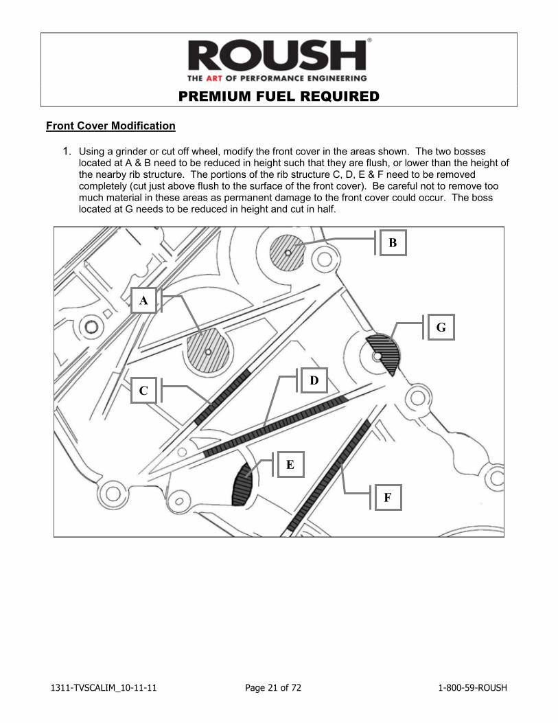
Front Cover Modification
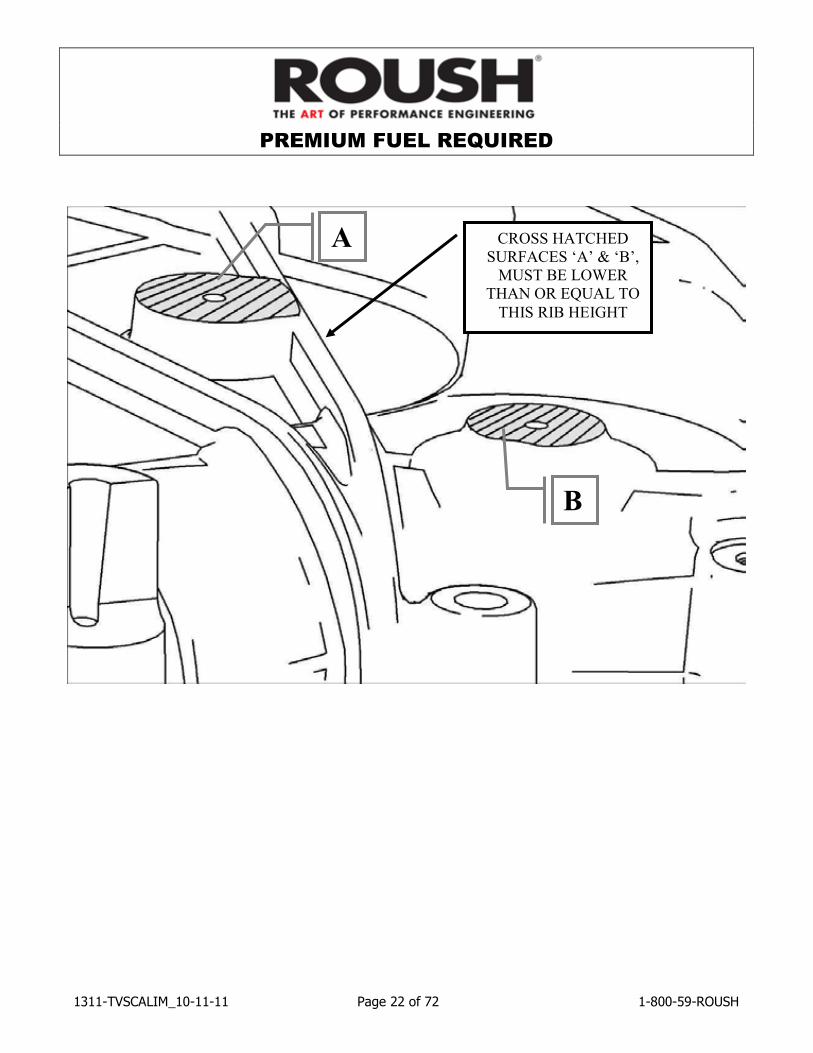
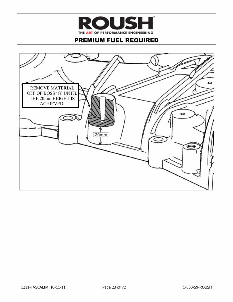
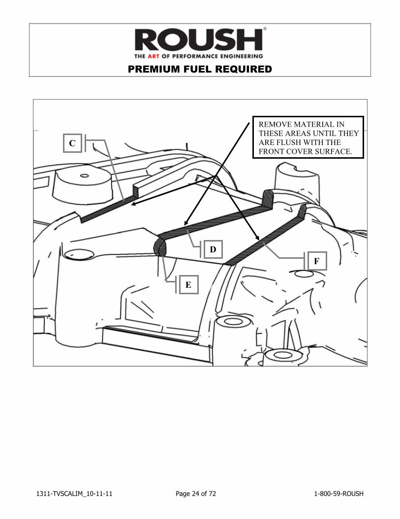
1. Using a grinder or cut off wheel, modify the front cover in the areas shown. The two bosses located at A & B need to be reduced in height such that they are flush, or lower than the height of the nearby rib structure. The portions of the rib structure C, D, E & F need to be removed completely (cut just above flush to the surface of the front cover). Be careful not to remove too much material in these areas as permanent damage to the front cover could occur. The boss located at G needs to be reduced in height and cut in half.
A
B
G
C D
E
F
PREMIUM FUEL REQUIRED
1311-TVSCALIM_10-11-11 Page 22 of 72 1-800-59-ROUSH
CROSS HATCHED
SURFACES ‘A’ & ‘B’,
MUST BE LOWER
THAN OR EQUAL TO
THIS RIB HEIGHT
A
B
PREMIUM FUEL REQUIRED
1311-TVSCALIM_10-11-11 Page 23 of 72 1-800-59-ROUSH
REMOVE MATERIAL
OFF OF BOSS ‘G’ UNTIL
THE 20mm HEIGHT IS
ACHIEVED.
PREMIUM FUEL REQUIRED
1311-TVSCALIM_10-11-11 Page 24 of 72 1-800-59-ROUSH
REMOVE MATERIAL IN
THESE AREAS UNTIL THEY
ARE FLUSH WITH THE
FRONT COVER SURFACE. C
D
E
F
PREMIUM FUEL REQUIRED
1311-TVSCALIM_10-11-11 Page 25 of 72 1-800-59-ROUSH
TPS/ETC Wiring
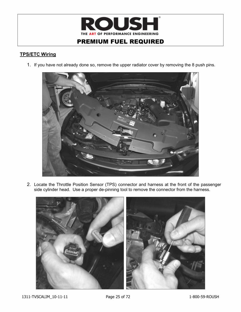
1. If you have not already done so, remove the upper radiator cover by removing the 8 push pins.
2. Locate the Throttle Position Sensor (TPS) connector and harness at the front of the passenger side cylinder head. Use a proper de-pinning tool to remove the connector from the harness.

PREMIUM FUEL REQUIRED
1311-TVSCALIM_10-11-11 Page 26 of 72 1-800-59-ROUSH
3. Depress the locking tab and separate the “empty” female 1 x 6 connector from the new TPS/ETC Extension harness (131114A595). It will be used in the next step.
4. Populate the new connector such that the yellow with violet wire is in position 1, the blue with green wire is in position 2, the brown wire is in position 3, the blue with orange wire is in position 4, the yellow wire is in position 5 and the green with violet wire is in position 6. Install the red plastic lock into the connector to secure the wires in place.
PREMIUM FUEL REQUIRED
1311-TVSCALIM_10-11-11 Page 27 of 72 1-800-59-ROUSH
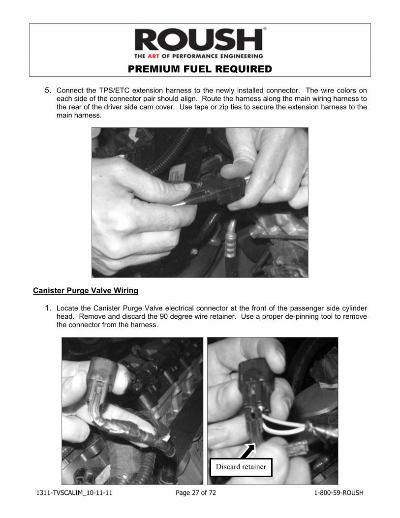
5. Connect the TPS/ETC extension harness to the newly installed connector. The wire colors on
each side of the connector pair should align. Route the harness along the main wiring harness to the rear of the driver side cam cover. Use tape or zip ties to secure the extension harness to the main harness.
Canister Purge Valve Wiring
1. Locate the Canister Purge Valve electrical connector at the front of the passenger side cylinder head. Remove and discard the 90 degree wire retainer. Use a proper de-pinning tool to remove the connector from the harness.
Discard retainer
PREMIUM FUEL REQUIRED
1311-TVSCALIM_10-11-11 Page 28 of 72 1-800-59-ROUSH
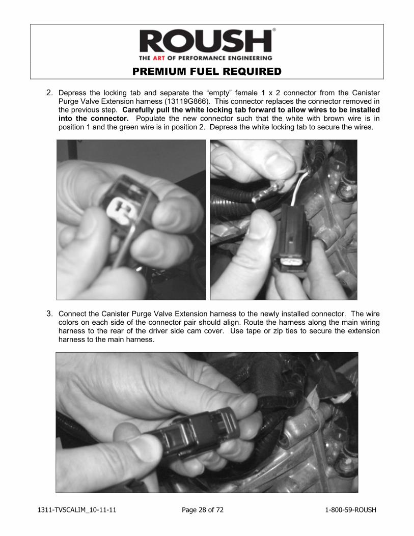
2. Depress the locking tab and separate the “empty” female 1 x 2 connector from the Canister Purge Valve Extension harness (13119G866). This connector replaces the connector removed in the previous step. Carefully pull the white locking tab forward to allow wires to be installed into the connector. Populate the new connector such that the white with brown wire is in position 1 and the green wire is in position 2. Depress the white locking tab to secure the wires.
3. Connect the Canister Purge Valve Extension harness to the newly installed connector. The wire colors on each side of the connector pair should align. Route the harness along the main wiring harness to the rear of the driver side cam cover. Use tape or zip ties to secure the extension harness to the main harness.
PREMIUM FUEL REQUIRED
1311-TVSCALIM_10-11-11 Page 29 of 72 1-800-59-ROUSH
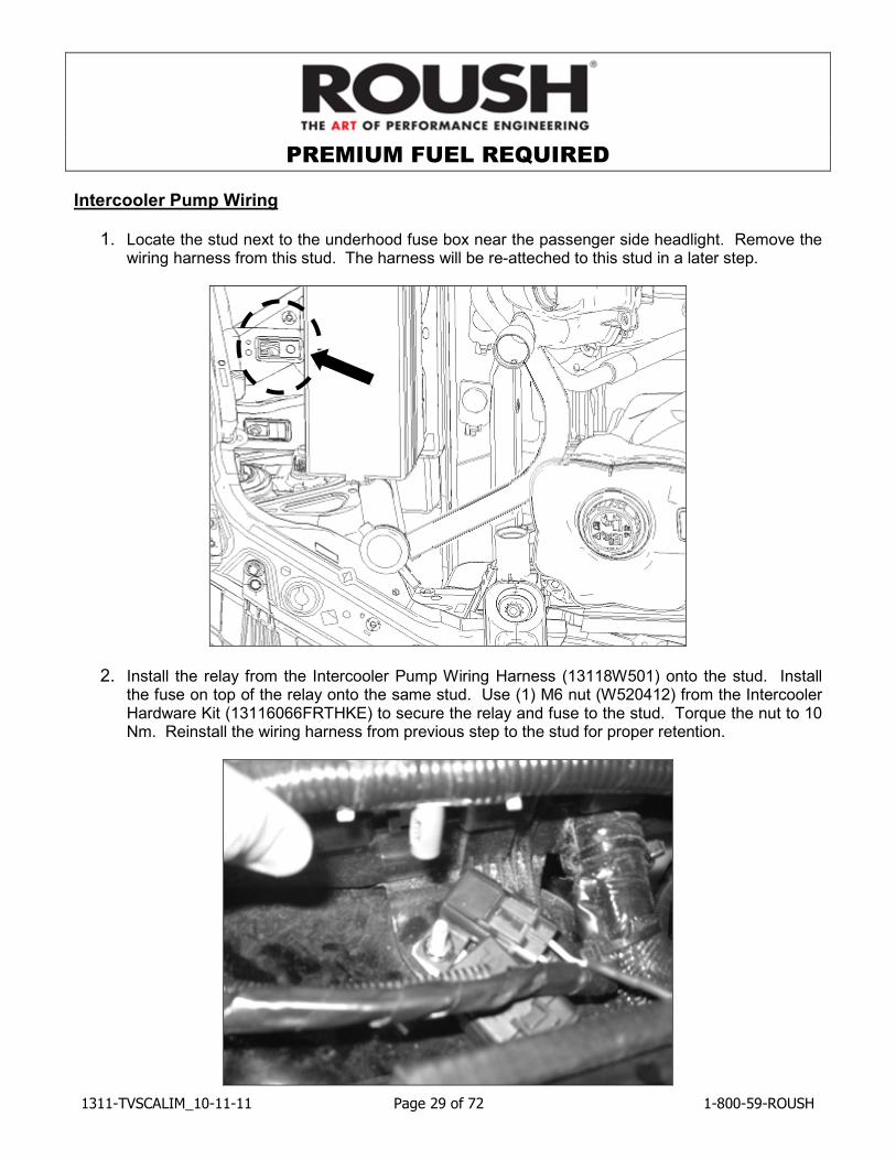
Intercooler Pump Wiring
1. Locate the stud next to the underhood fuse box near the passenger side headlight. Remove the wiring harness from this stud. The harness will be re-atteched to this stud in a later step.
2. Install the relay from the Intercooler Pump Wiring Harness (13118W501) onto the stud. Install the fuse on top of the relay onto the same stud. Use (1) M6 nut (W520412) from the Intercooler Hardware Kit (13116066FRTHKE) to secure the relay and fuse to the stud. Torque the nut to 10 Nm. Reinstall the wiring harness from previous step to the stud for proper retention.
PREMIUM FUEL REQUIRED
1311-TVSCALIM_10-11-11 Page 30 of 72 1-800-59-ROUSH
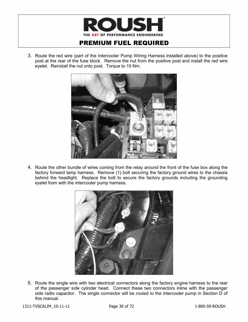
3. Route the red wire (part of the Intercooler Pump Wiring Harness installed above) to the positive post at the rear of the fuse block. Remove the nut from the positive post and install the red wire eyelet. Reinstall the nut onto post. Torque to 10 Nm.
4. Route the other bundle of wires coming from the relay around the front of the fuse box along the factory forward lamp harness. Remove (1) bolt securing the factory ground wires to the chassis behind the headlight. Replace the bolt to secure the factory grounds including the grounding eyelet from with the intercooler pump harness.
5. Route the single wire with two electrical connectors along the factory engine harness to the rear of the passenger side cylinder head. Connect these two connectors inline with the passenger side radio capacitor. The single connector will be routed to the intercooler pump in Section D of this manual.
PREMIUM FUEL REQUIRED
1311-TVSCALIM_10-11-11 Page 31 of 72 1-800-59-ROUSH
Air Charge Temperature (ACT) Wiring
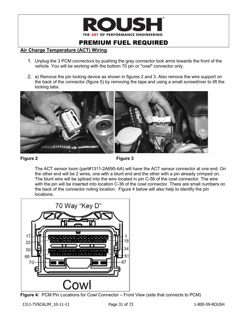
1. Unplug the 3 PCM connectors by pushing the gray connector lock arms towards the front of the vehicle. You will be working with the bottom 70 pin or "cowl" connector only.
2. a) Remove the pin locking device as shown in figures 2 and 3. Also remove the wire support on the back of the connector (figure 5) by removing the tape and using a small screwdriver to lift the locking tabs.
Figure 2 Figure 3
The ACT sensor loom (part#1311-2A690-AA) will have the ACT sensor connector at one end. On the other end will be 2 wires, one with a blunt end and the other with a pin already crimped on. The blunt wire will be spliced into the wire located in pin C-56 of the cowl connector. The wire with the pin will be inserted into location C-36 of the cowl connector. There are small numbers on the back of the connector noting location. Figure 4 below will also help to identify the pin locations.
Figure 4: PCM Pin Locations for Cowl Connector – Front View (side that connects to PCM)
PREMIUM FUEL REQUIRED
1311-TVSCALIM_10-11-11 Page 32 of 72 1-800-59-ROUSH
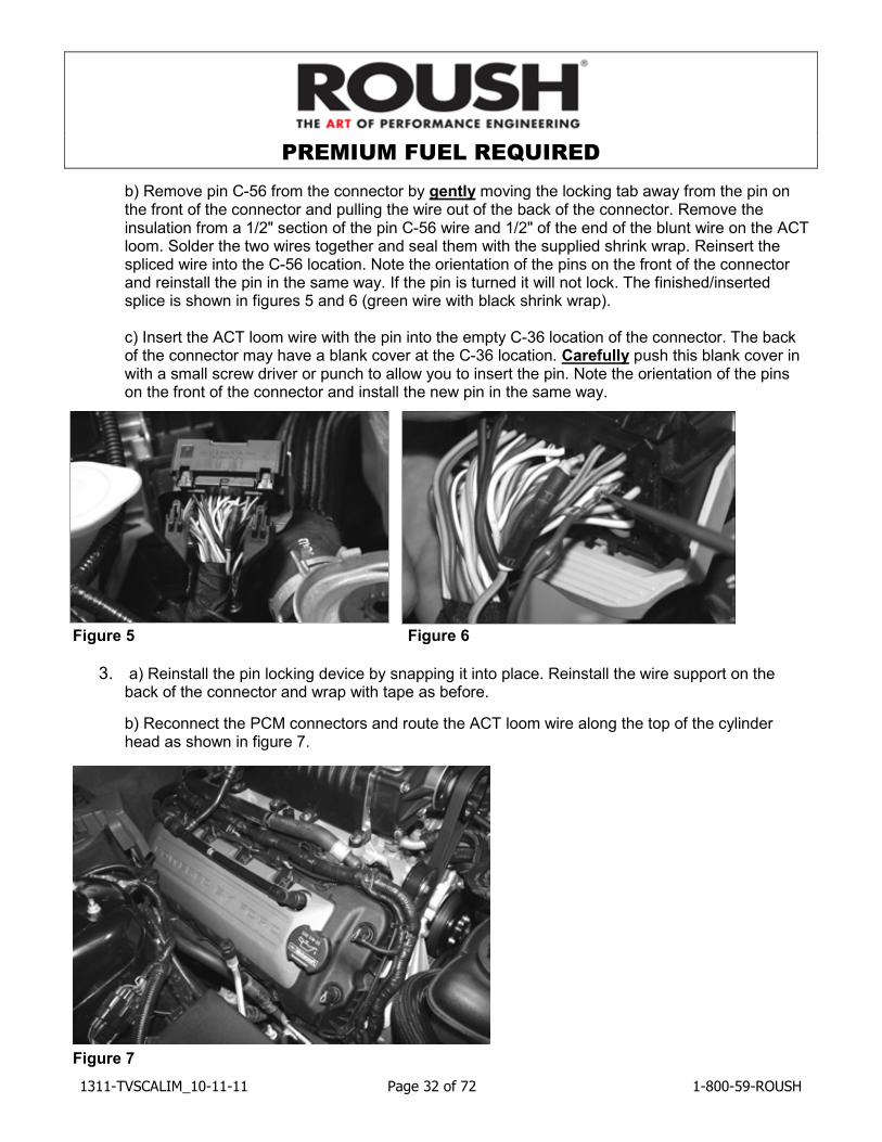
b) Remove pin C-56 from the connector by gently moving the locking tab away from the pin on the front of the connector and pulling the wire out of the back of the connector. Remove the insulation from a 1/2" section of the pin C-56 wire and 1/2" of the end of the blunt wire on the ACT loom. Solder the two wires together and seal them with the supplied shrink wrap. Reinsert the spliced wire into the C-56 location. Note the orientation of the pins on the front of the connector and reinstall the pin in the same way. If the pin is turned it will not lock. The finished/inserted splice is shown in figures 5 and 6 (green wire with black shrink wrap).
c) Insert the ACT loom wire with the pin into the empty C-36 location of the connector. The back of the connector may have a blank cover at the C-36 location. Carefully push this blank cover in with a small screw driver or punch to allow you to insert the pin. Note the orientation of the pins on the front of the connector and install the new pin in the same way.
Figure 5 Figure 6
3. a) Reinstall the pin locking device by snapping it into place. Reinstall the wire support on the back of the connector and wrap with tape as before.
b) Reconnect the PCM connectors and route the ACT loom wire along the top of the cylinder head as shown in figure 7.
Figure 7
PREMIUM FUEL REQUIRED
1311-TVSCALIM_10-11-11 Page 33 of 72 1-800-59-ROUSH
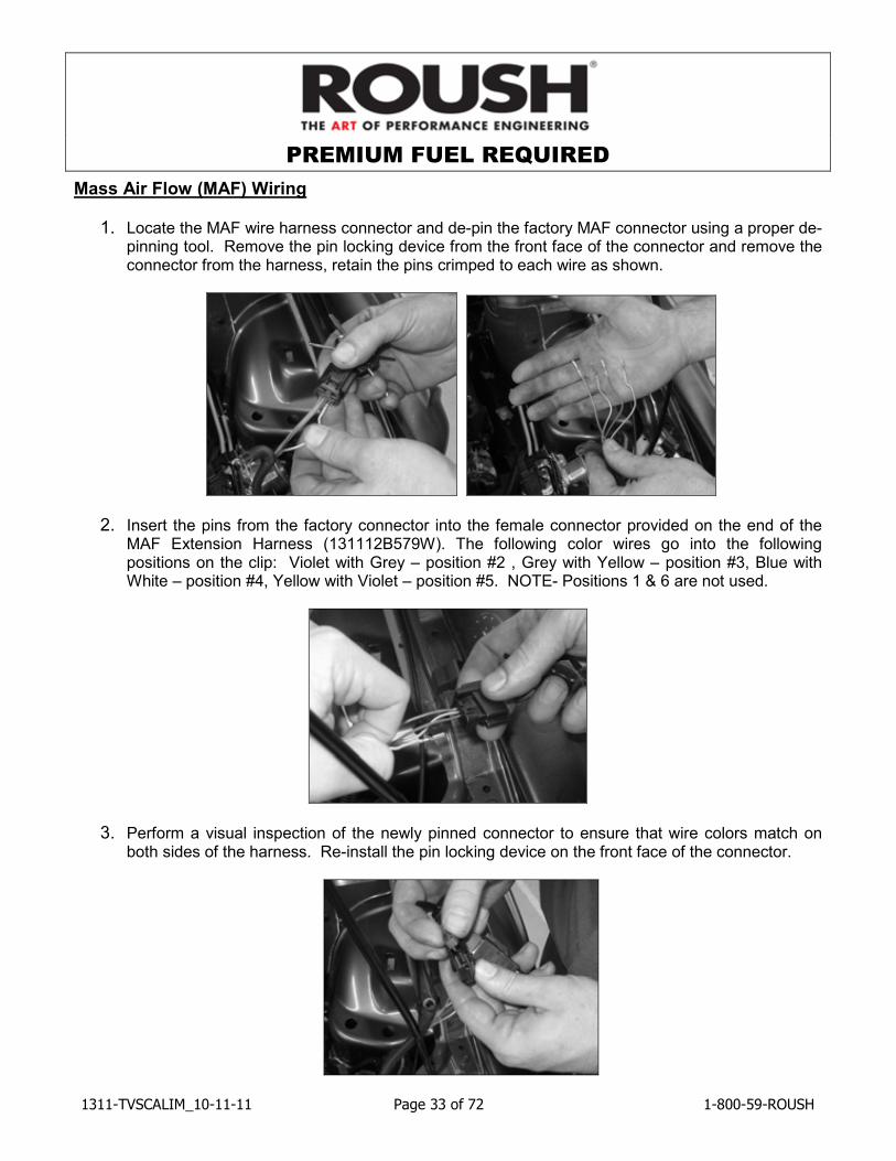
Mass Air Flow (MAF) Wiring
1. Locate the MAF wire harness connector and de-pin the factory MAF connector using a proper de-pinning tool. Remove the pin locking device from the front face of the connector and remove the connector from the harness, retain the pins crimped to each wire as shown.
2. Insert the pins from the factory connector into the female connector provided on the end of the MAF Extension Harness (131112B579W). The following color wires go into the following positions on the clip: Violet with Grey – position #2 , Grey with Yellow – position #3, Blue with White – position #4, Yellow with Violet – position #5. NOTE- Positions 1 & 6 are not used.
3. Perform a visual inspection of the newly pinned connector to ensure that wire colors match on both sides of the harness. Re-install the pin locking device on the front face of the connector.
PREMIUM FUEL REQUIRED
1311-TVSCALIM_10-11-11 Page 34 of 72 1-800-59-ROUSH
4. Connect the new MAF extension harness to the new connector and route the MAF extension harness around the outer perimeter of the lower air filter tray.
Knock Sensor Orientation Adjustment
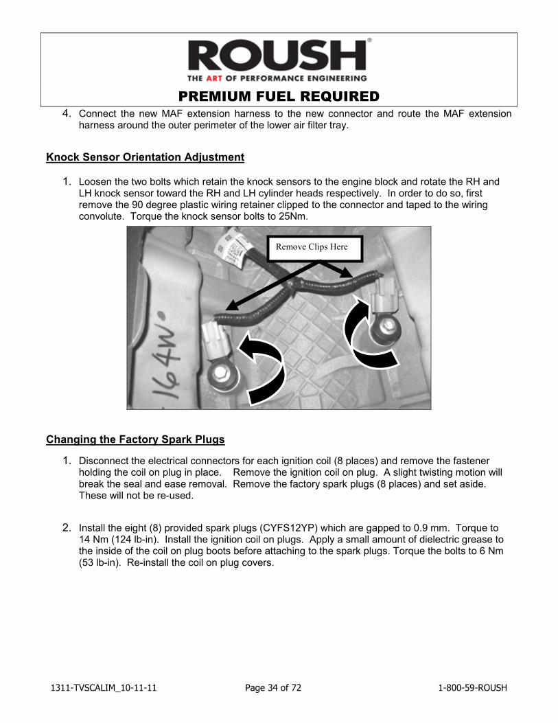
1. Loosen the two bolts which retain the knock sensors to the engine block and rotate the RH and LH knock sensor toward the RH and LH cylinder heads respectively. In order to do so, first remove the 90 degree plastic wiring retainer clipped to the connector and taped to the wiring convolute. Torque the knock sensor bolts to 25Nm.
Changing the Factory Spark Plugs
1. Disconnect the electrical connectors for each ignition coil (8 places) and remove the fastener holding the coil on plug in place. Remove the ignition coil on plug. A slight twisting motion will break the seal and ease removal. Remove the factory spark plugs (8 places) and set aside. These will not be re-used.
2. Install the eight (8) provided spark plugs (CYFS12YP) which are gapped to 0.9 mm. Torque to 14 Nm (124 lb-in). Install the ignition coil on plugs. Apply a small amount of dielectric grease to the inside of the coil on plug boots before attaching to the spark plugs. Torque the bolts to 6 Nm (53 lb-in). Re-install the coil on plug covers.
Remove Clips Here
PREMIUM FUEL REQUIRED
1311-TVSCALIM_10-11-11 Page 35 of 72 1-800-59-ROUSH
SECTION C – SUBASSEMBLY Intercooler Low Temperature Radiator (LTR)
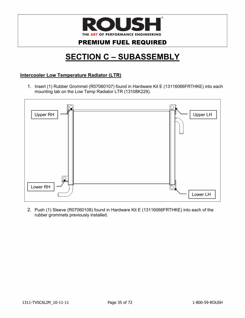
1. Insert (1) Rubber Grommet (R07060107) found in Hardware Kit E (13116066FRTHKE) into each mounting tab on the Low Temp Radiator LTR (13108K229).
2. Push (1) Sleeve (R07060108) found in Hardware Kit E (13116066FRTHKE) into each of the rubber grommets previously installed.
Upper LH
Lower RH
Lower LH
Upper RH
PREMIUM FUEL REQUIRED
1311-TVSCALIM_10-11-11 Page 36 of 72 1-800-59-ROUSH
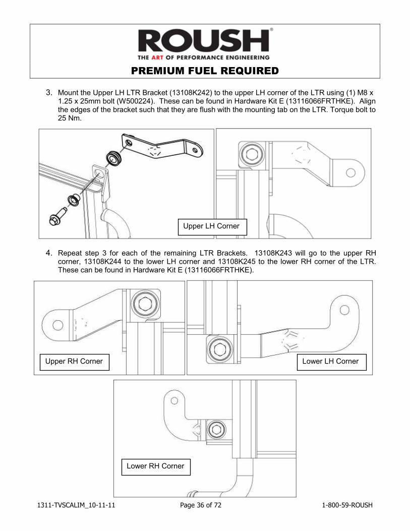
3. Mount the Upper LH LTR Bracket (13108K242) to the upper LH corner of the LTR using (1) M8 x
1.25 x 25mm bolt (W500224). These can be found in Hardware Kit E (13116066FRTHKE). Align the edges of the bracket such that they are flush with the mounting tab on the LTR. Torque bolt to 25 Nm.
4. Repeat step 3 for each of the remaining LTR Brackets. 13108K243 will go to the upper RH corner, 13108K244 to the lower LH corner and 13108K245 to the lower RH corner of the LTR. These can be found in Hardware Kit E (13116066FRTHKE).
Upper RH Corner Lower LH Corner
Lower RH Corner
Upper LH Corner
PREMIUM FUEL REQUIRED
1311-TVSCALIM_10-11-11 Page 37 of 72 1-800-59-ROUSH
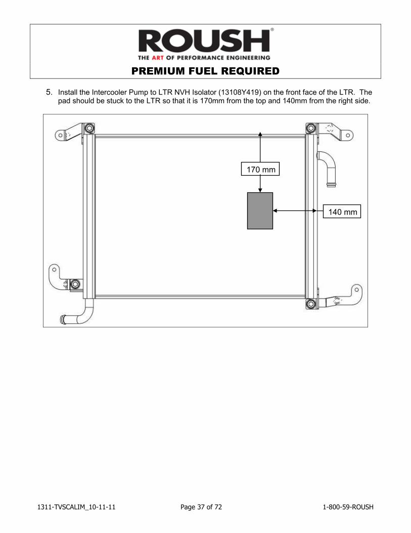
5. Install the Intercooler Pump to LTR NVH Isolator (13108Y419) on the front face of the LTR. The pad should be stuck to the LTR so that it is 170mm from the top and 140mm from the right side.
170 mm
140 mm
PREMIUM FUEL REQUIRED
1311-TVSCALIM_10-11-11 Page 38 of 72 1-800-59-ROUSH
Intake Manifold Build Up
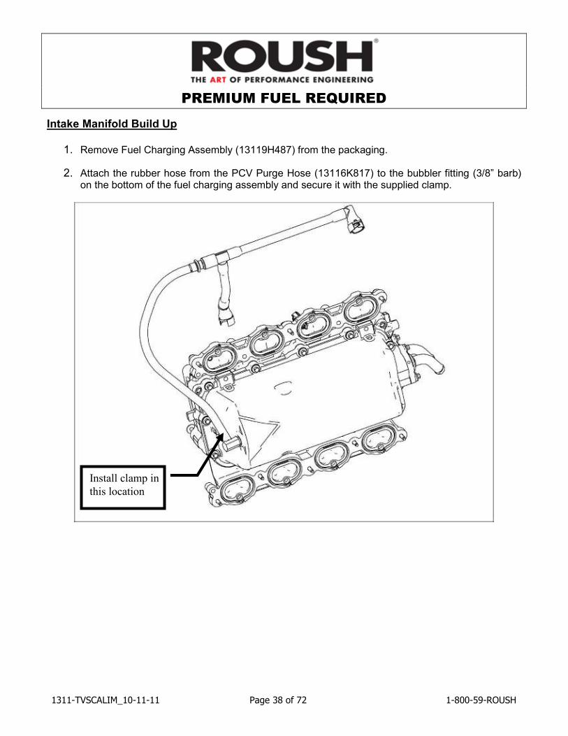
1. Remove Fuel Charging Assembly (13119H487) from the packaging.
2. Attach the rubber hose from the PCV Purge Hose (13116K817) to the bubbler fitting (3/8” barb) on the bottom of the fuel charging assembly and secure it with the supplied clamp.
Install clamp in
this location
PREMIUM FUEL REQUIRED
1311-TVSCALIM_10-11-11 Page 39 of 72 1-800-59-ROUSH
Throttle Body Spacer Assembly
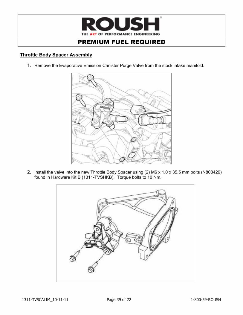
1. Remove the Evaporative Emission Canister Purge Valve from the stock intake manifold.
2. Install the valve into the new Throttle Body Spacer using (2) M6 x 1.0 x 35.5 mm bolts (N808429) found in Hardware Kit B (1311-TVSHKB). Torque bolts to 10 Nm.
PREMIUM FUEL REQUIRED
1311-TVSCALIM_10-11-11 Page 40 of 72 1-800-59-ROUSH
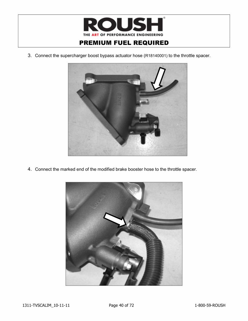
3. Connect the supercharger boost bypass actuator hose (R18140001) to the throttle spacer.
4. Connect the marked end of the modified brake booster hose to the throttle spacer.
PREMIUM FUEL REQUIRED
1311-TVSCALIM_10-11-11 Page 41 of 72 1-800-59-ROUSH
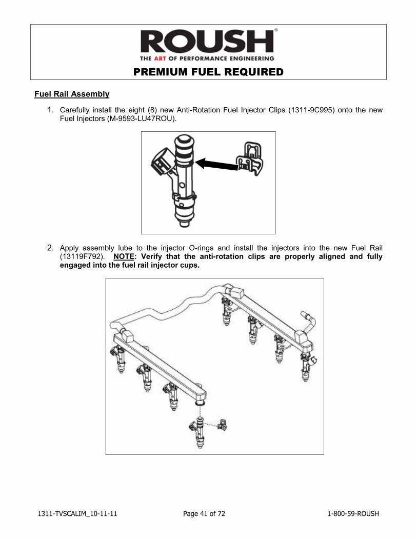
Fuel Rail Assembly
1. Carefully install the eight (8) new Anti-Rotation Fuel Injector Clips (1311-9C995) onto the new Fuel Injectors (M-9593-LU47ROU).
2. Apply assembly lube to the injector O-rings and install the injectors into the new Fuel Rail (13119F792). NOTE: Verify that the anti-rotation clips are properly aligned and fully engaged into the fuel rail injector cups.
PREMIUM FUEL REQUIRED
1311-TVSCALIM_10-11-11 Page 42 of 72 1-800-59-ROUSH
SECTION D – INSTALLATION
The following section will guide you through the final installation of the kit into the vehicle. If you need to stop during any part of the installation, make sure you cover any open ports in the cylinder heads or intake manifold to prevent foreign material from contaminating your engine.
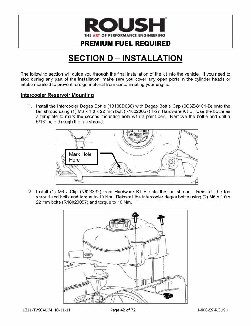
Intercooler Reservoir Mounting
1. Install the Intercooler Degas Bottle (13108D080) with Degas Bottle Cap (9C3Z-8101-B) onto the fan shroud using (1) M6 x 1.0 x 22 mm bolt (R18020057) from Hardware Kit E. Use the bottle as a template to mark the second mounting hole with a paint pen. Remove the bottle and drill a 5/16” hole through the fan shroud.
2. Install (1) M6 J-Clip (N623332) from Hardware Kit E onto the fan shroud. Reinstall the fan shroud and bolts and torque to 10 Nm. Reinstall the intercooler degas bottle using (2) M6 x 1.0 x 22 mm bolts (R18020057) and torque to 10 Nm.
Mark Hole Here
PREMIUM FUEL REQUIRED
1311-TVSCALIM_10-11-11 Page 43 of 72 1-800-59-ROUSH
Intercooler Radiator Assembly Mounting
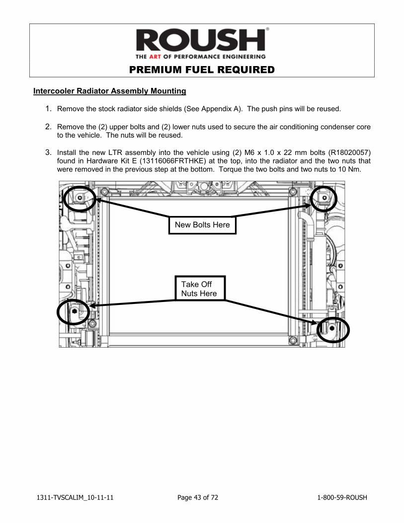
1. Remove the stock radiator side shields (See Appendix A). The push pins will be reused.
2. Remove the (2) upper bolts and (2) lower nuts used to secure the air conditioning condenser core
to the vehicle. The nuts will be reused.
3. Install the new LTR assembly into the vehicle using (2) M6 x 1.0 x 22 mm bolts (R18020057) found in Hardware Kit E (13116066FRTHKE) at the top, into the radiator and the two nuts that were removed in the previous step at the bottom. Torque the two bolts and two nuts to 10 Nm.
New Bolts Here
Take Off Nuts Here
PREMIUM FUEL REQUIRED
1311-TVSCALIM_10-11-11 Page 44 of 72 1-800-59-ROUSH
Electric Water Pump, Mounting Bracket and Hoses
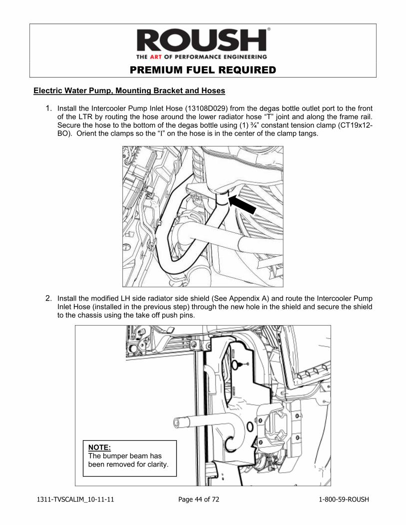
1. Install the Intercooler Pump Inlet Hose (13108D029) from the degas bottle outlet port to the front of the LTR by routing the hose around the lower radiator hose “T” joint and along the frame rail. Secure the hose to the bottom of the degas bottle using (1) ¾” constant tension clamp (CT19x12-BO). Orient the clamps so the “I” on the hose is in the center of the clamp tangs.
2. Install the modified LH side radiator side shield (See Appendix A) and route the Intercooler Pump Inlet Hose (installed in the previous step) through the new hole in the shield and secure the shield to the chassis using the take off push pins.
NOTE: The bumper beam has been removed for clarity.
PREMIUM FUEL REQUIRED
1311-TVSCALIM_10-11-11 Page 45 of 72 1-800-59-ROUSH
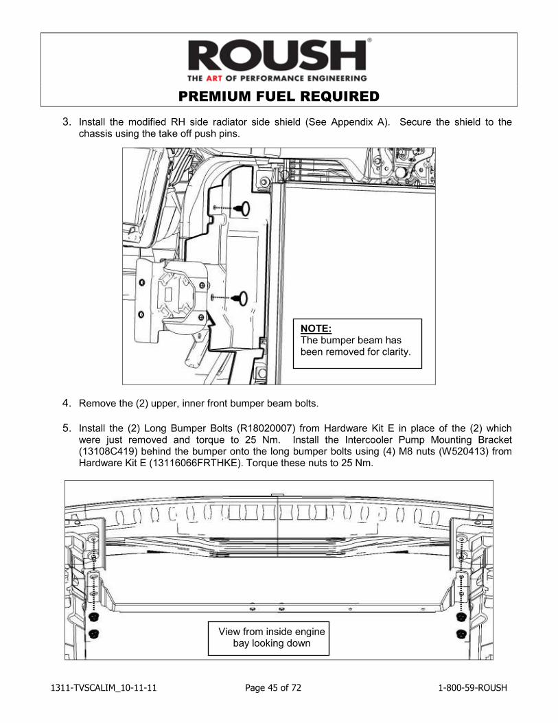
3. Install the modified RH side radiator side shield (See Appendix A). Secure the shield to the chassis using the take off push pins.
4. Remove the (2) upper, inner front bumper beam bolts.
5. Install the (2) Long Bumper Bolts (R18020007) from Hardware Kit E in place of the (2) which
were just removed and torque to 25 Nm. Install the Intercooler Pump Mounting Bracket (13108C419) behind the bumper onto the long bumper bolts using (4) M8 nuts (W520413) from Hardware Kit E (13116066FRTHKE). Torque these nuts to 25 Nm.
View from inside engine bay looking down
NOTE: The bumper beam has been removed for clarity.
PREMIUM FUEL REQUIRED
1311-TVSCALIM_10-11-11 Page 46 of 72 1-800-59-ROUSH
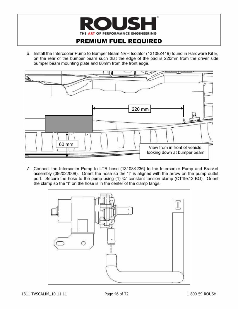
6. Install the Intercooler Pump to Bumper Beam NVH Isolator (13108Z419) found in Hardware Kit E, on the rear of the bumper beam such that the edge of the pad is 220mm from the driver side bumper beam mounting plate and 60mm from the front edge.
7. Connect the Intercooler Pump to LTR hose (13108K236) to the Intercooler Pump and Bracket assembly (392022009). Orient the hose so the “I” is aligned with the arrow on the pump outlet
port. Secure the hose to the pump using (1) ¾” constant tension clamp (CT19x12-BO). Orient the clamp so the “I” on the hose is in the center of the clamp tangs.
220 mm
60 mm View from in front of vehicle, looking down at bumper beam
PREMIUM FUEL REQUIRED
1311-TVSCALIM_10-11-11 Page 47 of 72 1-800-59-ROUSH
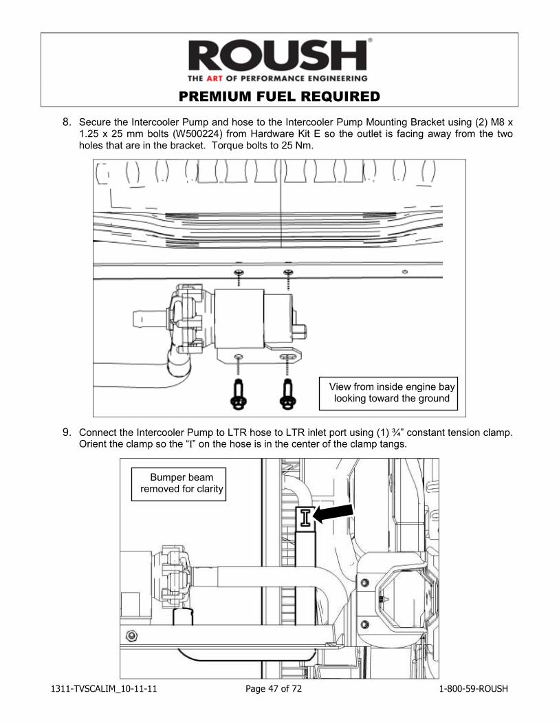
8. Secure the Intercooler Pump and hose to the Intercooler Pump Mounting Bracket using (2) M8 x 1.25 x 25 mm bolts (W500224) from Hardware Kit E so the outlet is facing away from the two holes that are in the bracket. Torque bolts to 25 Nm.
9. Connect the Intercooler Pump to LTR hose to LTR inlet port using (1) ¾” constant tension clamp. Orient the clamp so the “I” on the hose is in the center of the clamp tangs.
View from inside engine bay looking toward the ground
Bumper beam removed for clarity
PREMIUM FUEL REQUIRED
1311-TVSCALIM_10-11-11 Page 48 of 72 1-800-59-ROUSH
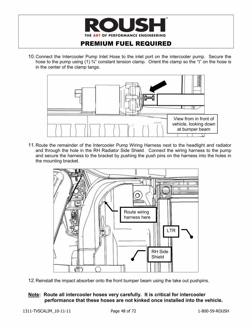
10. Connect the Intercooler Pump Inlet Hose to the inlet port on the intercooler pump. Secure the hose to the pump using (1) ¾” constant tension clamp. Orient the clamp so the “I” on the hose is
in the center of the clamp tangs.
11. Route the remainder of the Intercooler Pump Wiring Harness next to the headlight and radiator and through the hole in the RH Radiator Side Shield. Connect the wiring harness to the pump and secure the harness to the bracket by pushing the push pins on the harness into the holes in the mounting bracket.
12. Reinstall the impact absorber onto the front bumper beam using the take out pushpins.
Note: Route all intercooler hoses very carefully. It is critical for intercooler performance that these hoses are not kinked once installed into the vehicle.
Route wiring harness here
View from in front of vehicle, looking down at bumper beam
RH Side Shield
LTR
PREMIUM FUEL REQUIRED
1311-TVSCALIM_10-11-11 Page 49 of 72 1-800-59-ROUSH
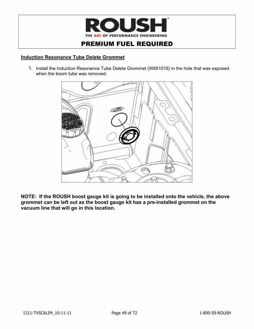
Induction Resonance Tube Delete Grommet
1. Install the Induction Resonance Tube Delete Grommet (W651016) in the hole that was exposed when the boom tube was removed.
NOTE: If the ROUSH boost gauge kit is going to be installed onto the vehicle, the above grommet can be left out as the boost gauge kit has a pre-installed grommet on the vacuum line that will go in this location.
PREMIUM FUEL REQUIRED
1311-TVSCALIM_10-11-11 Page 50 of 72 1-800-59-ROUSH
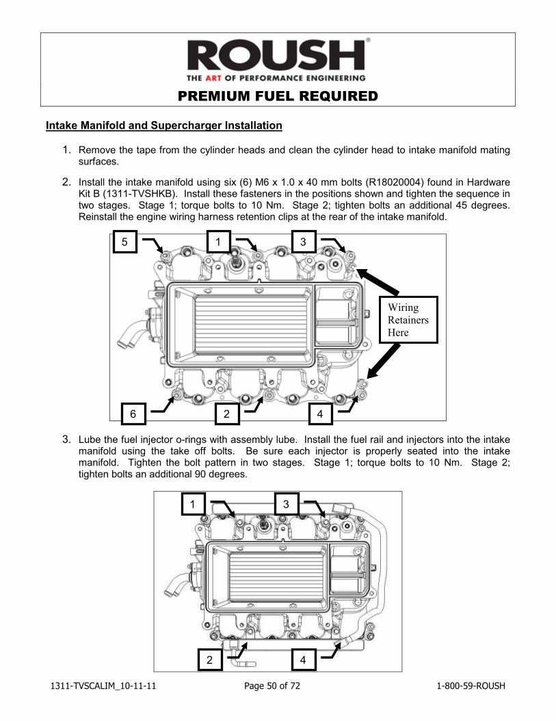
Intake Manifold and Supercharger Installation
1. Remove the tape from the cylinder heads and clean the cylinder head to intake manifold mating surfaces.
2. Install the intake manifold using six (6) M6 x 1.0 x 40 mm bolts (R18020004) found in Hardware Kit B (1311-TVSHKB). Install these fasteners in the positions shown and tighten the sequence in two stages. Stage 1; torque bolts to 10 Nm. Stage 2; tighten bolts an additional 45 degrees. Reinstall the engine wiring harness retention clips at the rear of the intake manifold.
3. Lube the fuel injector o-rings with assembly lube. Install the fuel rail and injectors into the intake manifold using the take off bolts. Be sure each injector is properly seated into the intake manifold. Tighten the bolt pattern in two stages. Stage 1; torque bolts to 10 Nm. Stage 2; tighten bolts an additional 90 degrees.
6 2 4
5 1 3
1
2 4
3
Wiring
Retainers
Here
PREMIUM FUEL REQUIRED
1311-TVSCALIM_10-11-11 Page 51 of 72 1-800-59-ROUSH
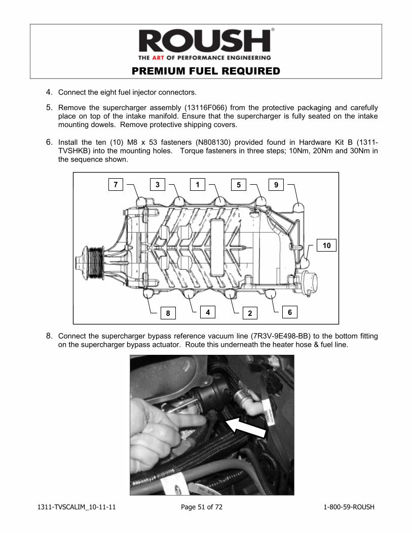
4. Connect the eight fuel injector connectors.
5. Remove the supercharger assembly (13116F066) from the protective packaging and carefully place on top of the intake manifold. Ensure that the supercharger is fully seated on the intake mounting dowels. Remove protective shipping covers.
6. Install the ten (10) M8 x 53 fasteners (N808130) provided found in Hardware Kit B (1311-TVSHKB) into the mounting holes. Torque fasteners in three steps; 10Nm, 20Nm and 30Nm in the sequence shown.
8. Connect the supercharger bypass reference vacuum line (7R3V-9E498-BB) to the bottom fitting on the supercharger bypass actuator. Route this underneath the heater hose & fuel line.
3 7
8
1 5 9
6 4 2
10

PREMIUM FUEL REQUIRED
1311-TVSCALIM_10-11-11 Page 52 of 72 1-800-59-ROUSH
9. Install the throttle spacer to supercharger gasket (R07060152) between the throttle body spacer assembly and the supercharger and mount the spacer using (4) M6 x 32 fasteners (R18020009). These parts can be found in Hardware Kit B (1311-TVSHKB). Torque the fasteners to 10 Nm.
10. Connect the boost bypass hose from the throttle body spacer to the top port of the supercharger bypass actuator.
11. Connect the brake booster vacuum line to the check valve on the brake booster.
PREMIUM FUEL REQUIRED
1311-TVSCALIM_10-11-11 Page 53 of 72 1-800-59-ROUSH
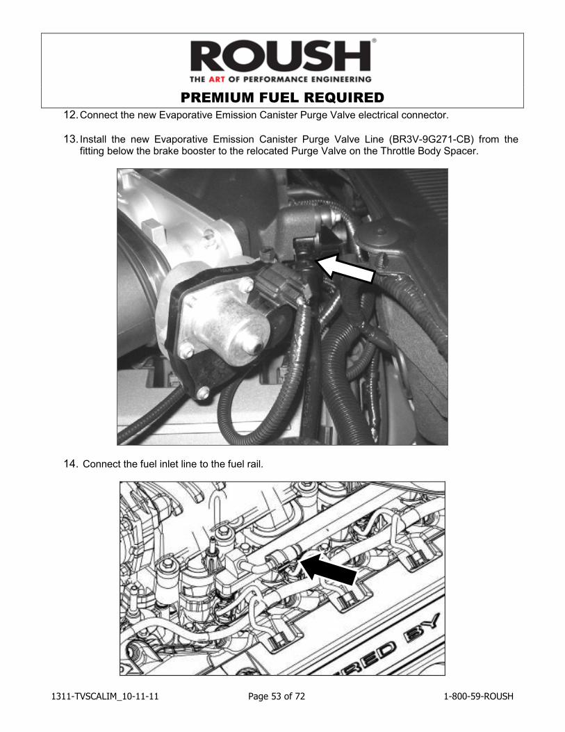
12. Connect the new Evaporative Emission Canister Purge Valve electrical connector.
13. Install the new Evaporative Emission Canister Purge Valve Line (BR3V-9G271-CB) from the fitting below the brake booster to the relocated Purge Valve on the Throttle Body Spacer.
14. Connect the fuel inlet line to the fuel rail.
PREMIUM FUEL REQUIRED
1311-TVSCALIM_10-11-11 Page 54 of 72 1-800-59-ROUSH
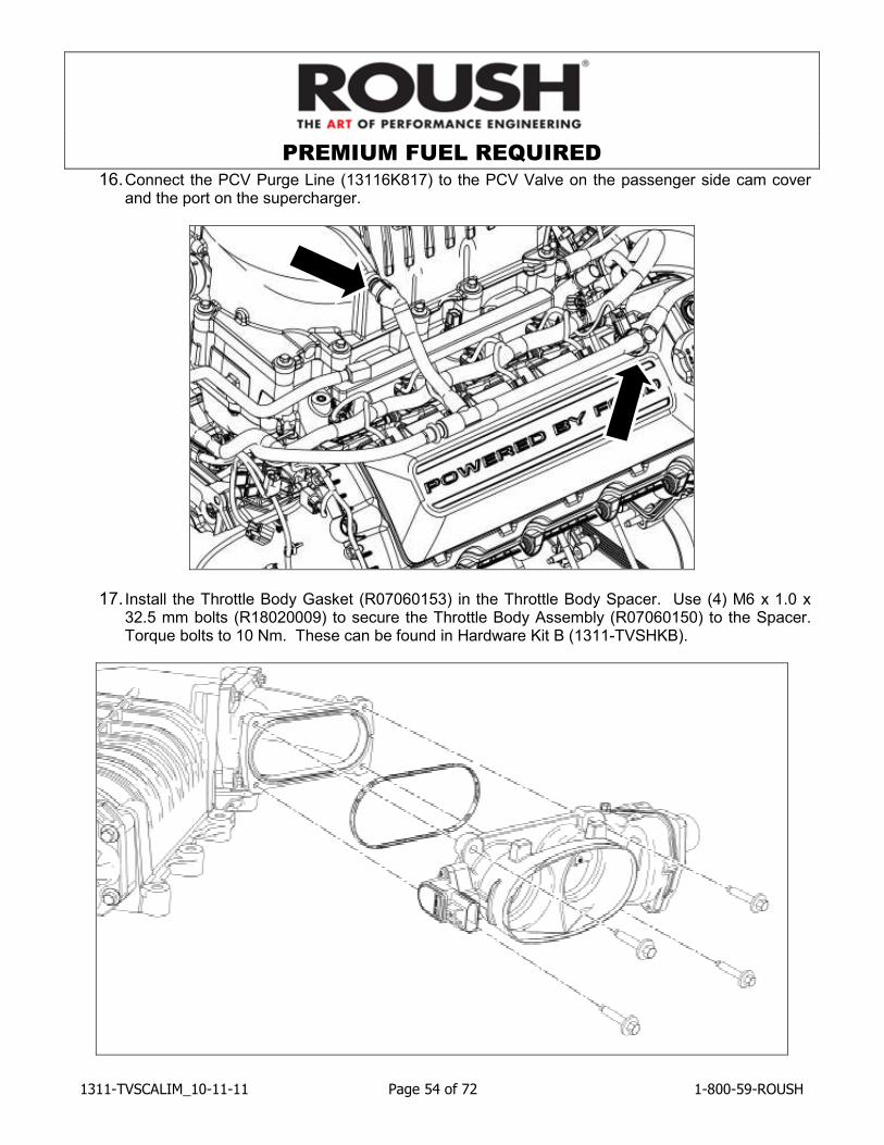
16. Connect the PCV Purge Line (13116K817) to the PCV Valve on the passenger side cam cover and the port on the supercharger.
17. Install the Throttle Body Gasket (R07060153) in the Throttle Body Spacer. Use (4) M6 x 1.0 x 32.5 mm bolts (R18020009) to secure the Throttle Body Assembly (R07060150) to the Spacer. Torque bolts to 10 Nm. These can be found in Hardware Kit B (1311-TVSHKB).
PREMIUM FUEL REQUIRED
1311-TVSCALIM_10-11-11 Page 55 of 72 1-800-59-ROUSH
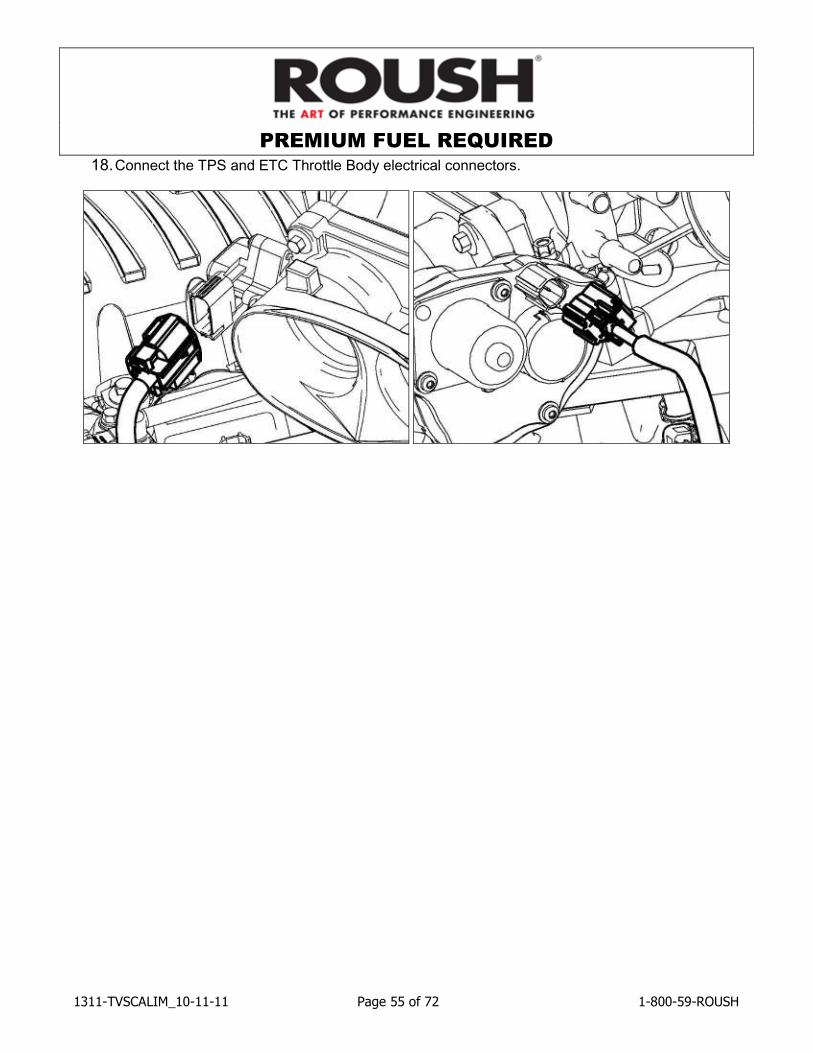
18. Connect the TPS and ETC Throttle Body electrical connectors.
PREMIUM FUEL REQUIRED
1311-TVSCALIM_10-11-11 Page 56 of 72 1-800-59-ROUSH
FEAD Assembly
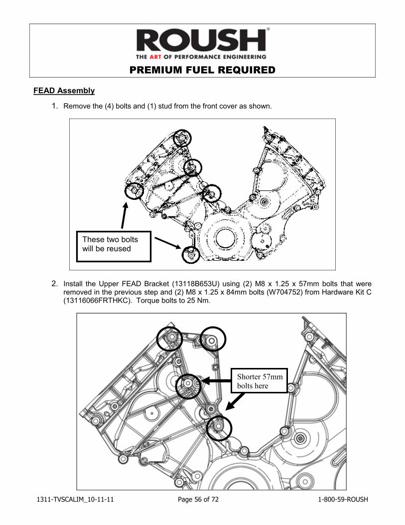
1. Remove the (4) bolts and (1) stud from the front cover as shown.
2. Install the Upper FEAD Bracket (13118B653U) using (2) M8 x 1.25 x 57mm bolts that were removed in the previous step and (2) M8 x 1.25 x 84mm bolts (W704752) from Hardware Kit C (13116066FRTHKC). Torque bolts to 25 Nm.
These two bolts will be reused
Shorter 57mm
bolts here
PREMIUM FUEL REQUIRED
1311-TVSCALIM_10-11-11 Page 57 of 72 1-800-59-ROUSH
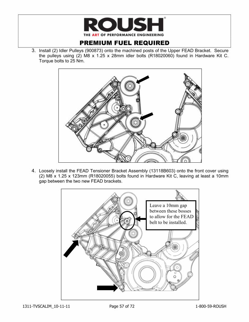
3. Install (2) Idler Pulleys (900873) onto the machined posts of the Upper FEAD Bracket. Secure the pulleys using (2) M8 x 1.25 x 28mm idler bolts (R18020060) found in Hardware Kit C. Torque bolts to 25 Nm.
4. Loosely install the FEAD Tensioner Bracket Assembly (13118B603) onto the front cover using (2) M8 x 1.25 x 123mm (R18020055) bolts found in Hardware Kit C, leaving at least a 10mm gap between the two new FEAD brackets.
Leave a 10mm gap
between these bosses
to allow for the FEAD
belt to be installed.
PREMIUM FUEL REQUIRED
1311-TVSCALIM_10-11-11 Page 58 of 72 1-800-59-ROUSH
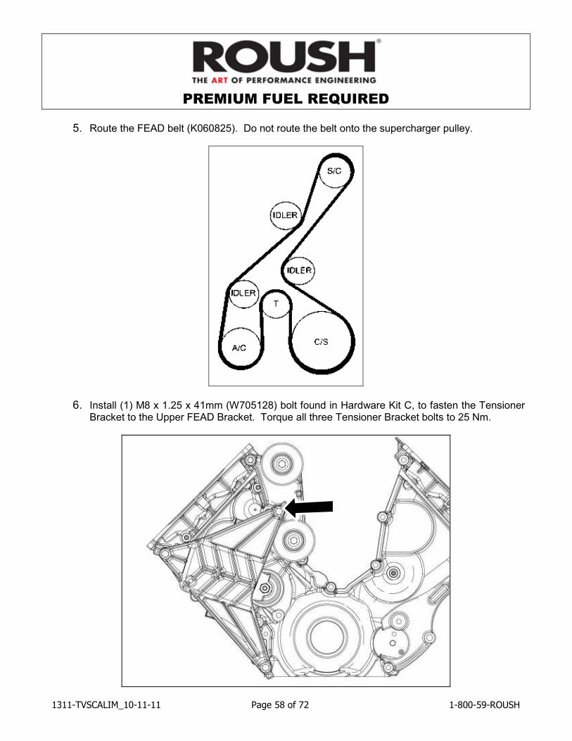
5. Route the FEAD belt (K060825). Do not route the belt onto the supercharger pulley.
6. Install (1) M8 x 1.25 x 41mm (W705128) bolt found in Hardware Kit C, to fasten the Tensioner Bracket to the Upper FEAD Bracket. Torque all three Tensioner Bracket bolts to 25 Nm.
PREMIUM FUEL REQUIRED
1311-TVSCALIM_10-11-11 Page 59 of 72 1-800-59-ROUSH
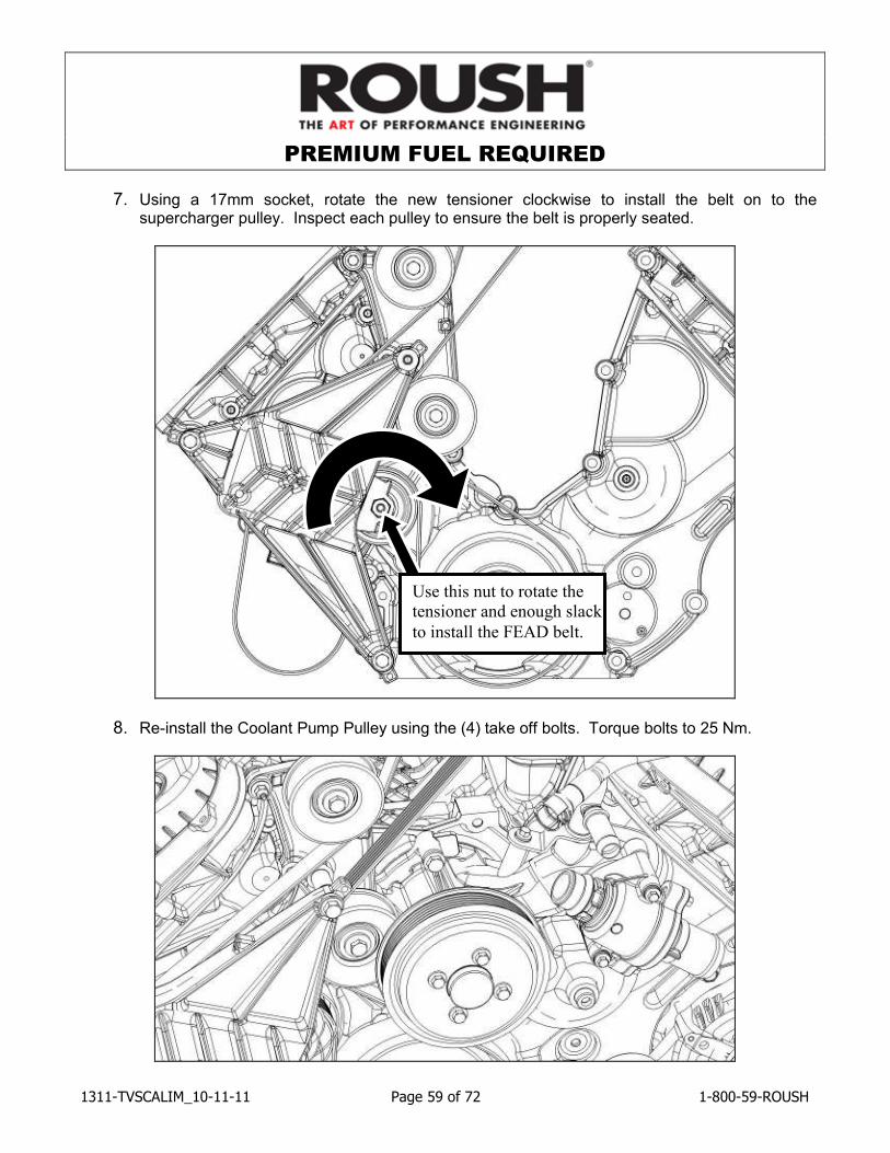
7. Using a 17mm socket, rotate the new tensioner clockwise to install the belt on to the supercharger pulley. Inspect each pulley to ensure the belt is properly seated.
8. Re-install the Coolant Pump Pulley using the (4) take off bolts. Torque bolts to 25 Nm.
Use this nut to rotate the
tensioner and enough slack
to install the FEAD belt.
PREMIUM FUEL REQUIRED
1311-TVSCALIM_10-11-11 Page 60 of 72 1-800-59-ROUSH
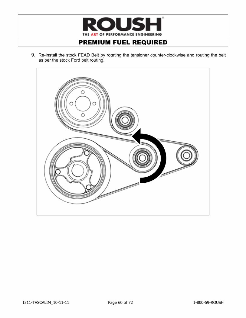
9. Re-install the stock FEAD Belt by rotating the tensioner counter-clockwise and routing the belt as per the stock Ford belt routing.
PREMIUM FUEL REQUIRED
1311-TVSCALIM_10-11-11 Page 61 of 72 1-800-59-ROUSH
Coolant Hoses
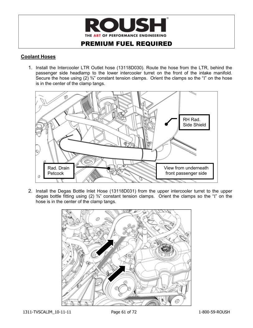
1. Install the Intercooler LTR Outlet hose (13118D030). Route the hose from the LTR, behind the passenger side headlamp to the lower intercooler turret on the front of the intake manifold. Secure the hose using (2) ¾” constant tension clamps. Orient the clamps so the “I” on the hose
is in the center of the clamp tangs.
2. Install the Degas Bottle Inlet Hose (13118D031) from the upper intercooler turret to the upper degas bottle fitting using (2) ¾” constant tension clamps. Orient the clamps so the “I” on the
hose is in the center of the clamp tangs.
View from underneath front passenger side
Rad. Drain Petcock
RH Rad. Side Shield
PREMIUM FUEL REQUIRED
1311-TVSCALIM_10-11-11 Page 62 of 72 1-800-59-ROUSH
3. Reinstall the upper radiator hose.
4. Reinstall the factory degas bottle onto the fan shroud and torque the bolt to 10Nm.
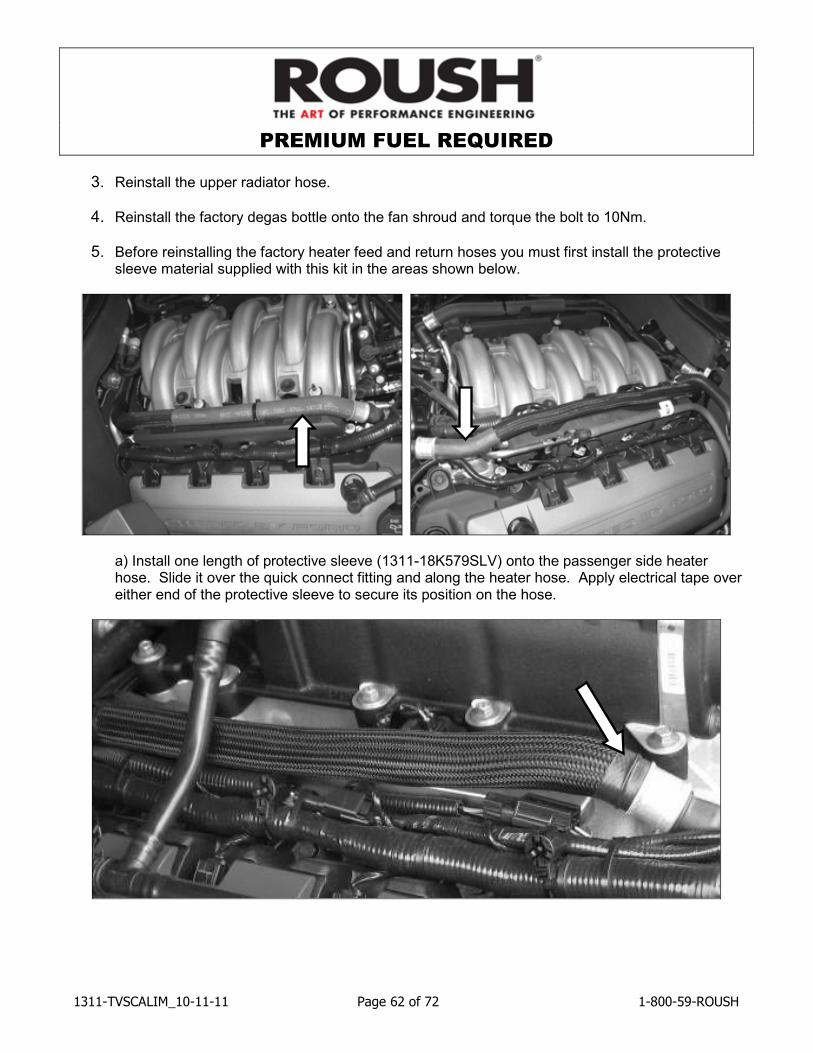
5. Before reinstalling the factory heater feed and return hoses you must first install the protective sleeve material supplied with this kit in the areas shown below.
a) Install one length of protective sleeve (1311-18K579SLV) onto the passenger side heater hose. Slide it over the quick connect fitting and along the heater hose. Apply electrical tape over either end of the protective sleeve to secure its position on the hose.
PREMIUM FUEL REQUIRED
1311-TVSCALIM_10-11-11 Page 63 of 72 1-800-59-ROUSH
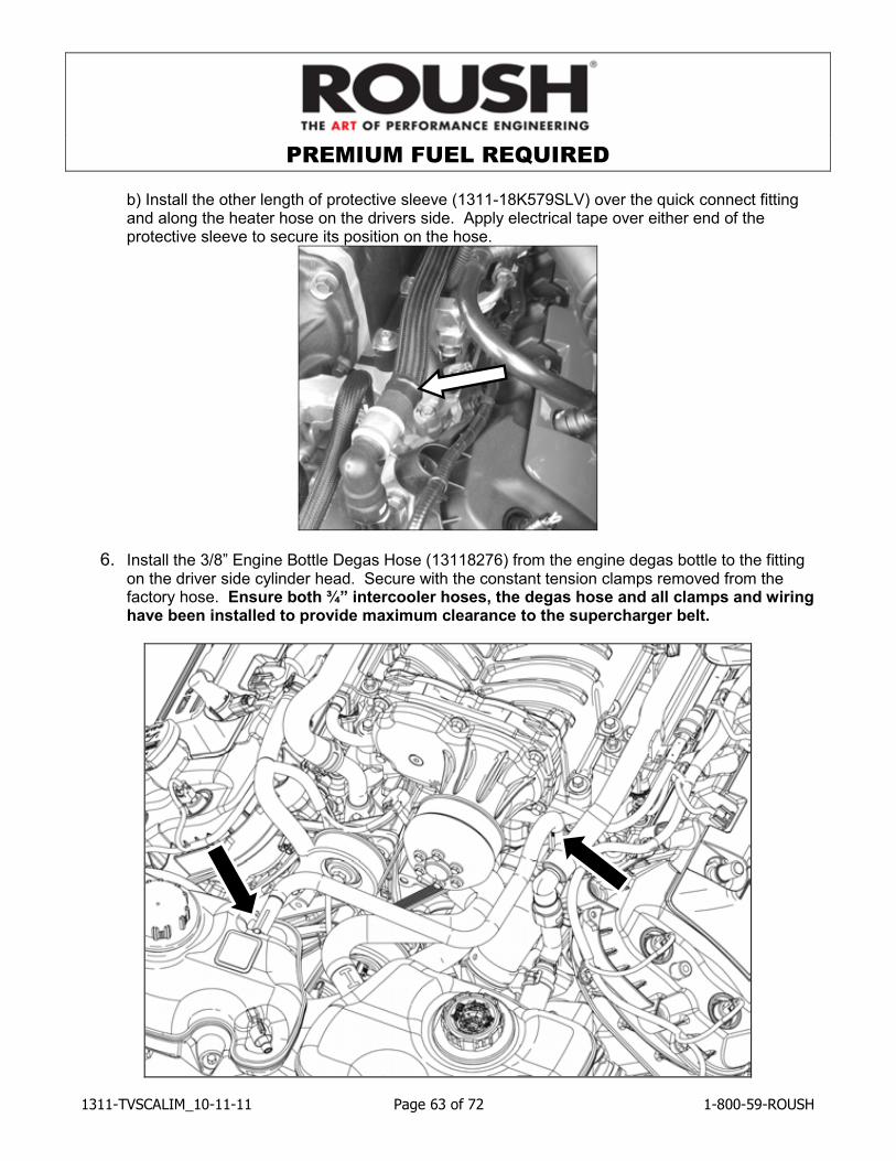
b) Install the other length of protective sleeve (1311-18K579SLV) over the quick connect fitting and along the heater hose on the drivers side. Apply electrical tape over either end of the protective sleeve to secure its position on the hose.
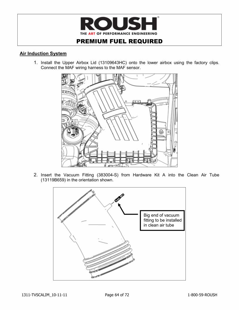
6. Install the 3/8” Engine Bottle Degas Hose (13118276) from the engine degas bottle to the fitting on the driver side cylinder head. Secure with the constant tension clamps removed from the factory hose. Ensure both ¾” intercooler hoses, the degas hose and all clamps and wiring have been installed to provide maximum clearance to the supercharger belt.
PREMIUM FUEL REQUIRED
1311-TVSCALIM_10-11-11 Page 64 of 72 1-800-59-ROUSH
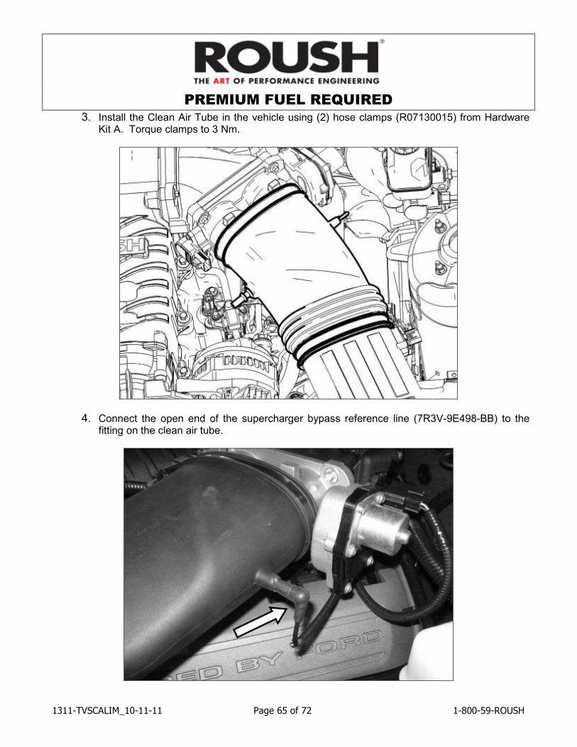
Air Induction System
1. Install the Upper Airbox Lid (13109643HC) onto the lower airbox using the factory clips. Connect the MAF wiring harness to the MAF sensor.
2. Insert the Vacuum Fitting (383004-S) from Hardware Kit A into the Clean Air Tube (13119B659) in the orientation shown.
Big end of vacuum fitting to be installed in clean air tube
PREMIUM FUEL REQUIRED
1311-TVSCALIM_10-11-11 Page 65 of 72 1-800-59-ROUSH
3. Install the Clean Air Tube in the vehicle using (2) hose clamps (R07130015) from Hardware Kit A. Torque clamps to 3 Nm.
4. Connect the open end of the supercharger bypass reference line (7R3V-9E498-BB) to the fitting on the clean air tube.
PREMIUM FUEL REQUIRED
1311-TVSCALIM_10-11-11 Page 66 of 72 1-800-59-ROUSH
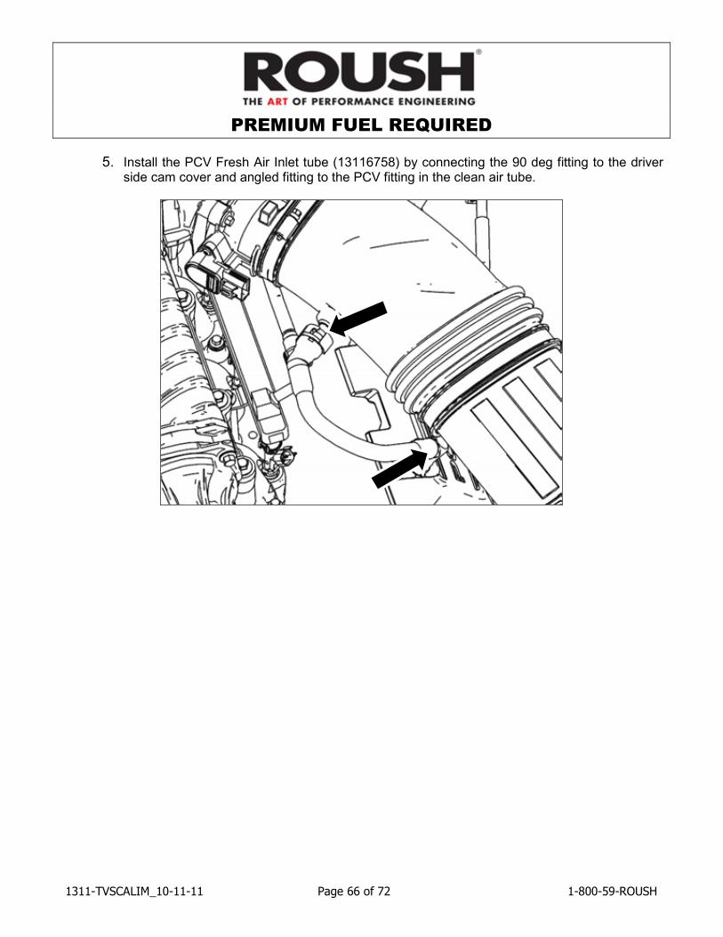
5. Install the PCV Fresh Air Inlet tube (13116758) by connecting the 90 deg fitting to the driver side cam cover and angled fitting to the PCV fitting in the clean air tube.
PREMIUM FUEL REQUIRED
1311-TVSCALIM_10-11-11 Page 67 of 72 1-800-59-ROUSH
Final Assembly
1. Fill the engine cooling system (using a proper coolant mixture) to the marked level on the radiator degas bottle.
2. Using the same coolant mixture, fill the intercooler system. The coolant should be approximately one inch below the top of the cap.
Important: Both coolant systems can trap a large amount of air. It is very important to verify that the air is purged and that coolant is flowing properly through both systems. Roush recommends vacuum filling both systems to properly evacuate the trapped air.
3. Reinstall front bumper cover, lower close-out panel and inner fenders by reversing the removal procedures.
4. Reinstall the front wheels/tires. Torque wheel lugs to the factory Ford specifications.
5. Inspect all underhood wiring harnesses for potential interference issues. Use zip ties to safely position the harness away from any areas of concern.
6. Reinstall the radiator trim cover by reversing the removal instructions.
7. Reinstall the battery connections by connecting the positive cable first then connecting the negative cable.
8. Reconnect the fuel pump control module electrical connector located in the spare tire stowage compartment.
9. In order to complete the installation of this kit, you must complete the PCM Removal Steps and the Shipping instructions found on pages 10 & 11 of these instructions. DO NOT ATTEMP TO START OR TO DRIVE THE VEHICLE UNTIL THE REPROGRAMED PCM HAS BEEN RETURNED AND RE-INSTALLED CORRECTLY INTO THE VEHICLE. OPERATING THE ENGINE WITHOUT THE RECALIBRATED PCM WILL RESULT IN ENGINE DAMAGE OR FAILURE AND WILL VOID THE WARRANTY.
10. Once the PCM has been successfully re-installed, start the engine and check for unusual noises, dash service lights, and unusual operation. If problems are detected, immediately stop the engine or vehicle, diagnose and repair the problem.
PREMIUM FUEL REQUIRED
1311-TVSCALIM_10-11-11 Page 68 of 72 1-800-59-ROUSH
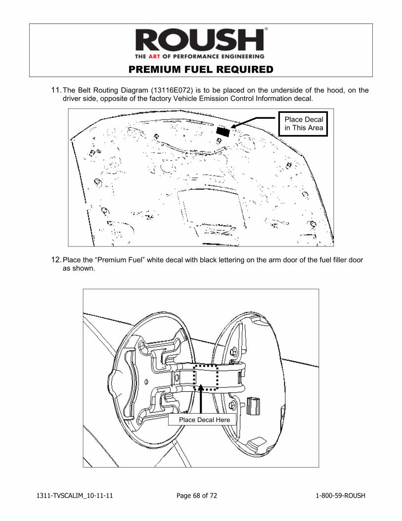
11. The Belt Routing Diagram (13116E072) is to be placed on the underside of the hood, on the driver side, opposite of the factory Vehicle Emission Control Information decal.
12. Place the “Premium Fuel” white decal with black lettering on the arm door of the fuel filler door as shown.
Place Decal in This Area
Place Decal Here
PREMIUM FUEL REQUIRED
1311-TVSCALIM_10-11-11 Page 69 of 72 1-800-59-ROUSH
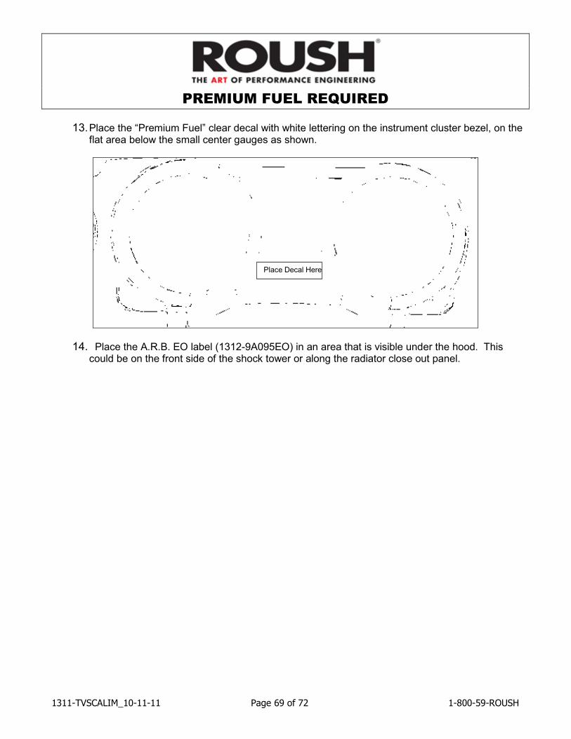
13. Place the “Premium Fuel” clear decal with white lettering on the instrument cluster bezel, on the flat area below the small center gauges as shown.
14. Place the A.R.B. EO label (1312-9A095EO) in an area that is visible under the hood. This could be on the front side of the shock tower or along the radiator close out panel.
Place Decal Here
PREMIUM FUEL REQUIRED
1311-TVSCALIM_10-11-11 Page 70 of 72 1-800-59-ROUSH
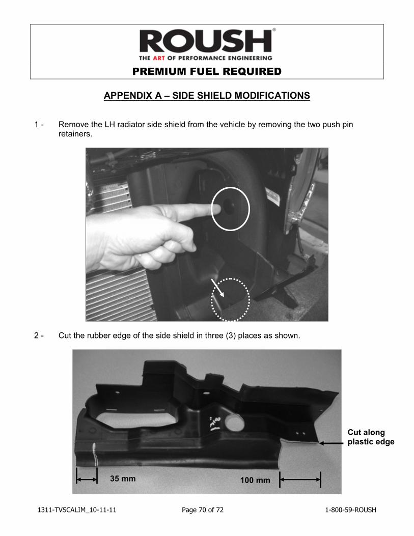
APPENDIX A – SIDE SHIELD MODIFICATIONS
1 - Remove the LH radiator side shield from the vehicle by removing the two push pin retainers.
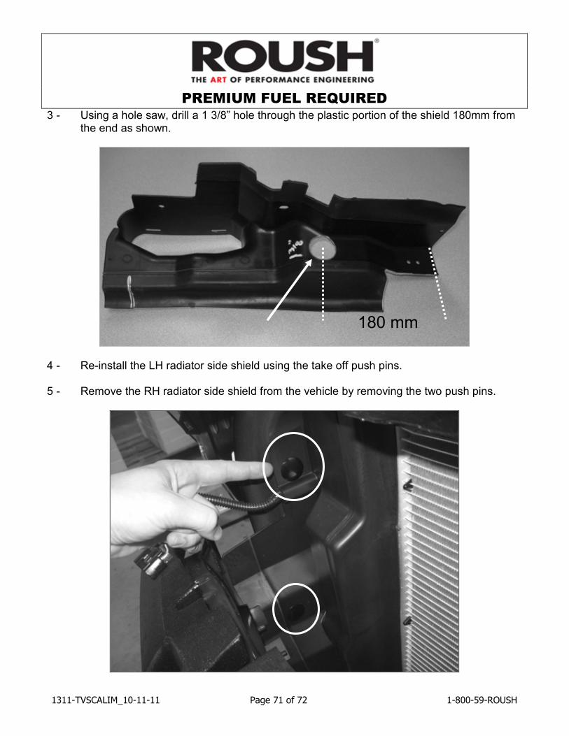
2 - Cut the rubber edge of the side shield in three (3) places as shown.
100 mm 35 mm
Cut along plastic edge
PREMIUM FUEL REQUIRED
1311-TVSCALIM_10-11-11 Page 71 of 72 1-800-59-ROUSH
3 - Using a hole saw, drill a 1 3/8” hole through the plastic portion of the shield 180mm from the end as shown.
4 - Re-install the LH radiator side shield using the take off push pins. 5 - Remove the RH radiator side shield from the vehicle by removing the two push pins.
180 mm
PREMIUM FUEL REQUIRED
1311-TVSCALIM_10-11-11 Page 72 of 72 1-800-59-ROUSH
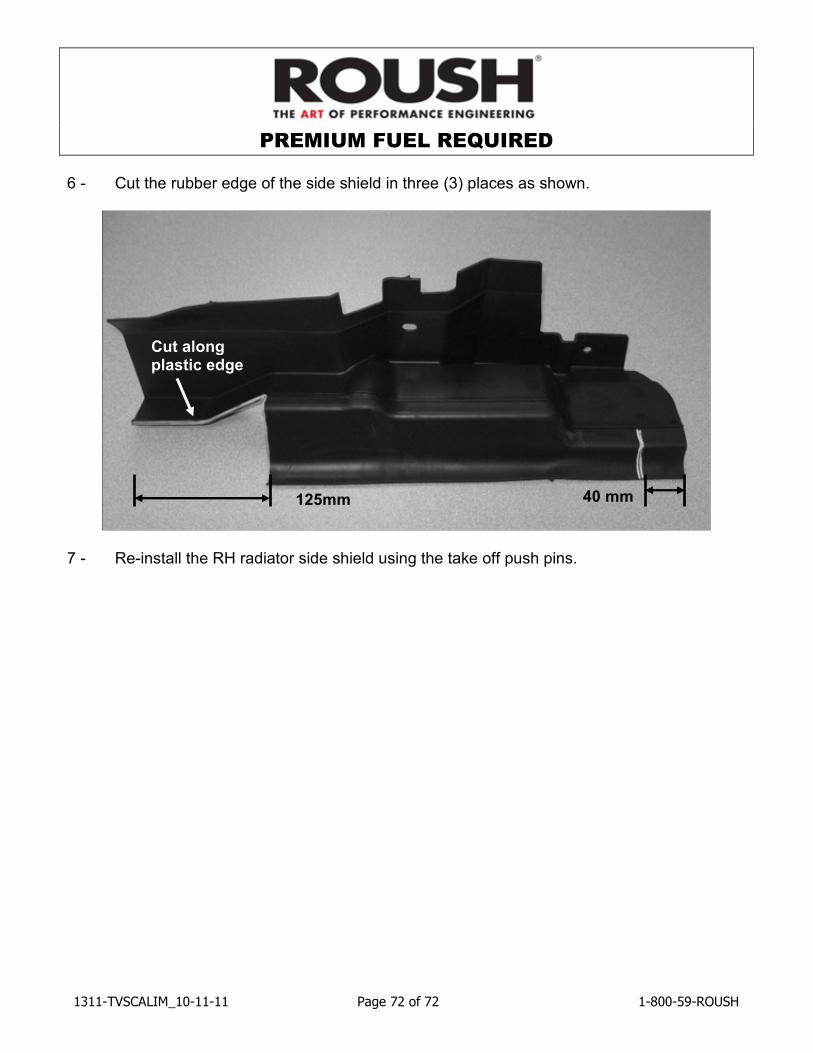
6 - Cut the rubber edge of the side shield in three (3) places as shown.
7 - Re-install the RH radiator side shield using the take off push pins.
40 mm 125mm
Cut along plastic edge