Embed Size (px)
Citation preview

Cleveland State University Cleveland State University
EngagedScholarship@CSU EngagedScholarship@CSU
ETD Archive
2014
Enzyme-Based Nitric Oxide Releasing Thin Films and Scaffolds Enzyme-Based Nitric Oxide Releasing Thin Films and Scaffolds
Mutha Merenna Nuwan Bhagya Gunasekera Cleveland State University
Follow this and additional works at: https://engagedscholarship.csuohio.edu/etdarchive
Part of the Chemistry Commons
How does access to this work benefit you? Let us know! How does access to this work benefit you? Let us know!
Recommended Citation Recommended Citation Gunasekera, Mutha Merenna Nuwan Bhagya, "Enzyme-Based Nitric Oxide Releasing Thin Films and Scaffolds" (2014). ETD Archive. 114. https://engagedscholarship.csuohio.edu/etdarchive/114
This Dissertation is brought to you for free and open access by EngagedScholarship@CSU. It has been accepted for inclusion in ETD Archive by an authorized administrator of EngagedScholarship@CSU. For more information, please contact [email protected].
ENZYME-BASED NITRIC OXIDE RELEASING THIN FILMS AND
SCAFFOLDS
MUTHA MERENNA NUWAN BHAGYA GUNASEKERA
Bachelor of Science in Biology
University of Colombo
August, 2003
Master of Science in Analytical Chemistry
University of Colombo
July, 2008
submitted in partial fulfillment of requirements for the degree
DOCTOR OF PHILOSOPHY IN CLINICAL-BIOANALYTICAL CHEMISTRY
at the
CLEVELAND STATE UNIVERSITY
May 2014

We hereby approve this dissertation
for
Mutha Merenna Nuwan Bhagya Gunasekera
Candidate for the Doctor of Philosophy in Clinical-Bioanalytical Chemistry Degree
for the
Department of Chemistry
and
CLEVELAND STATE UNIVERSITY’S
College of Graduate Studies
________________________________________ Mekki Bayachou. PhD.
Department of Chemistry / May 5th 2014
________________________________________ David W. Ball. PhD.
Department of Chemistry / May 5th 2014
________________________________________ John F. Turner. PhD.
Department of Chemistry / May 5th 2014
________________________________________ Parthasarathy Srinivasan. PhD.
Department of Mathematics / May 5th 2014
________________________________________ Gary Wnek. PhD.
Department of Macromolecular Science and Engineering,
Case Western Reserve University / May 5th 2014
Student’s Date of Defense: April 29th 2014

ACKNOWLEDGEMENTS
I thank first, my advisor Dr. Mekki Bayachou, for his help and guidance throughout
the years. Next, I thank members of the dissertation committee, Dr. David W. Ball, Dr.
John F. Turner, Dr. Parthasarathy Srinivasan and Dr. Gary Wnek for their time and advice.
I also thank faculty members and staff of the Department of Chemistry, College of Science
and Health Professions, College of Graduate Studies and the Center for International
Services and Programs for their help with coursework and administrative matters. I thank
past lab members of the Bayachou lab group for the work that I was able to build upon. I
also thankfully commit to my memory, all my peers of Bayachou group and Wnek group
(Case Western Reserve University) for their support.
I would like to dedicate this thesis to all my family members and all my teachers
whose blessings have always been with me.
iv
ENZYME-BASED NITRIC OXIDE RELEASING THIN FILMS AND
SCAFFOLDS
MUTHA MERENNA NUWAN BHAGYA GUNASEKERA
ABSTRACT
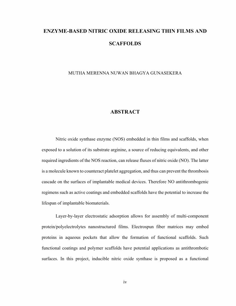
Nitric oxide synthase enzyme (NOS) embedded in thin films and scaffolds, when
exposed to a solution of its substrate arginine, a source of reducing equivalents, and other
required ingredients of the NOS reaction, can release fluxes of nitric oxide (NO). The latter
is a molecule known to counteract platelet aggregation, and thus can prevent the thrombosis
cascade on the surfaces of implantable medical devices. Therefore NO antithrombogenic
regimens such as active coatings and embedded scaffolds have the potential to increase the
lifespan of implantable biomaterials.
Layer-by-layer electrostatic adsorption allows for assembly of multi-component
protein/polyelectrolytes nanostructured films. Electrospun fiber matrices may embed
proteins in aqueous pockets that allow the formation of functional scaffolds. Such
functional coatings and polymer scaffolds have potential applications as antithrombotic
surfaces. In this project, inducible nitric oxide synthase is proposed as a functional

v
component in active thin films and electrospun scaffolds for nitric oxide release under
physiologic conditions.
Atomic force microscopic (AFM) imaging confirms the presence of enzyme in
adsorbed thin films. Fourier transform infrared (FTIR) spectroscopic analysis was used to
characterize structure-function relationships of NOS-containing thin films. Voltammetry
was used to characterize the active catalyst concentration on adsorbed surfaces and activity
of NOS-containing thin films. Further, analysis of cyclic voltammetric data enabled the
study of Michaelis-Menten kinetics of NOS-containing thin films. Other
spectrophotometric and spectrofluorometric assays were used to monitor nitric oxide
release for the NOS-based thin films and scaffolds. Three polymers were characterized for
their ability to embed iNOSoxy and show enzyme activity in electrospun scaffolds.
For the LbL method, during protein adsorption, an adjusted pH of 8.6 or the use of
a branched matrix immobilizes more enzyme units in thin layers compared to pH 7.0 or a
linearly structured polymer matrix. However, the enzyme structure adsorbed at pH 7.0
allows faster catalytic turnover of substrate compared to enzyme structure from pH 8.6
immobilization. Overall, both the cumulative nitric oxide output and the flux were higher
for films immobilized at pH 8.6 or adsorbed onto branched polymer matrices. Electrospun
fiber scaffolds produce nitric oxide when bathed in a cocktail containing the ingredients of
NOS catalyzed reaction.
vi
TABLE OF CONTENTS
Page
LIST OF TABLES .......................................................................................................... XI
LIST OF FIGURES ...................................................................................................... XII
NOMENCLATURE .................................................................................................. XVIII
GENERAL INTRODUCTION ........................................................................................ 1
Background ............................................................................................................. 1
Thrombogenesis ...................................................................................................... 2
Nitric oxide in antithrombogenic regimens ............................................................ 2
Nitric oxide and nitric oxide synthase .................................................................... 5
Mechanism of nitric oxide mediated antithrombogenesis ...................................... 8
Electrostatically adsorbed thin films of NOS enzyme ............................................ 9
NOS embedded electrospun scaffolds .................................................................. 11
NO as a short-lived reactive species and its significance in localized activity ..... 13
CHAPTER I: IMPROVED ENZYME LOADING IN LAYER-BY-LAYER (LBL)
ADSORBED THIN FILMS OF INDUCIBLE NITRIC OXIDE SYNTHASE (INOS)
AND POLYETHYLENIMINE (PEI) ........................................................................... 14
1.1 Introduction ............................................................................................... 14
1.1.1 Isoelectric point of iNOS and its significance .......................................... 15
1.2 Experimental ............................................................................................. 16

vii
1.2.1 Expression and purification of iNOSoxy through recombinant plasmid
DNA ................................................................................................................... 16
1.2.2 Adjustment of pH of protein in solution ................................................... 18
1.2.3 Atomic force microscopic (AFM) imaging of adsorbed thin films .......... 19
1.2.4 Electrochemical investigation of heme-Fe3+ reduction and catalytic NO
reduction by LbL immobilized PEI/iNOSoxy films on graphite electrodes ......... 20
1.2.5 Fourier Transform Infrared Spectroscopy (FTIR) on thin protein layers . 21
1.2.6 Griess assay for the determination of activity of thin films of PEI/iNOSoxy
................................................................................................................... 22
1.3 Results and discussion .............................................................................. 24
1.3.1 AFM images of iNOSoxy on PEI-modified surfaces ............................... 24
1.3.2 Electrocatalytic reduction of NO mediated by iNOSoxy in films ............ 29
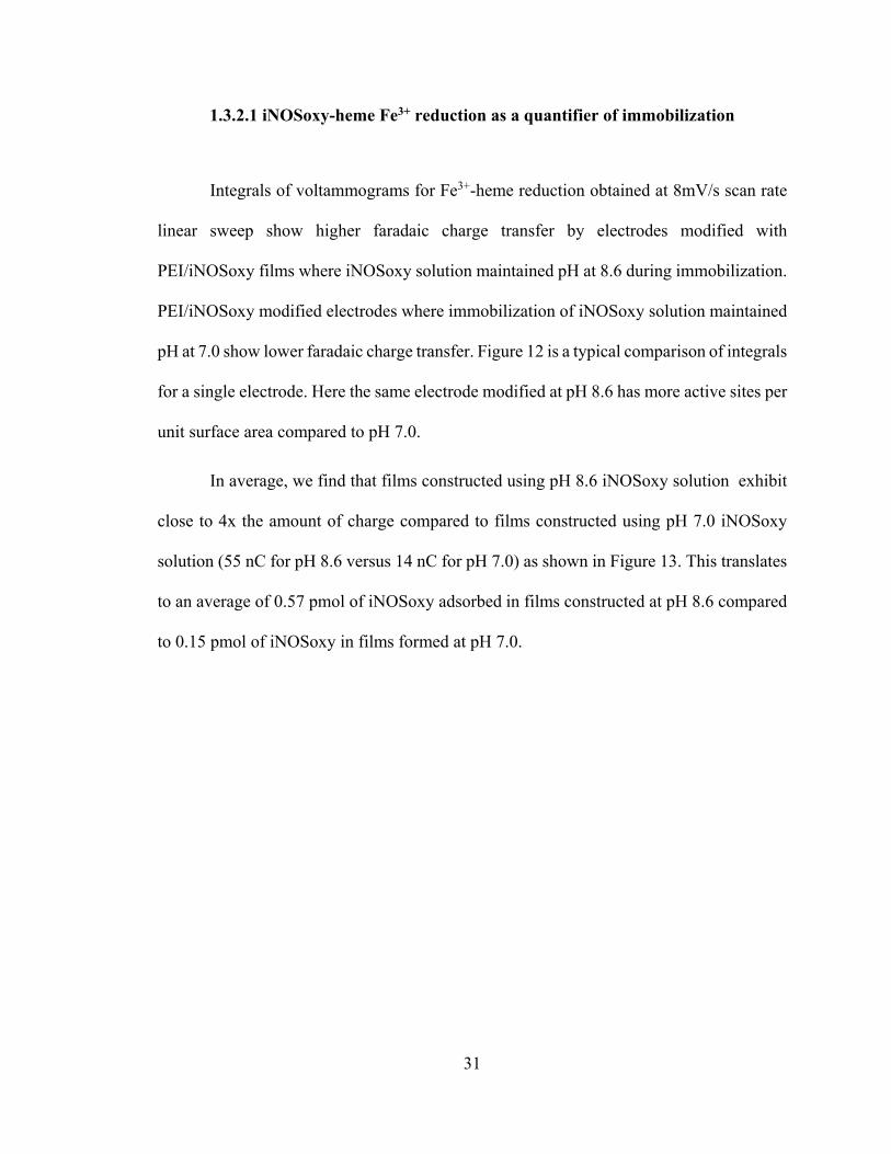
1.3.2.1 iNOSoxy-heme Fe3+ reduction as a quantifier of immobilization ....... 31
1.3.2.2 Catalytic reduction of NO mediated by iNOSoxy on PEI/iNOSoxy films
on PG electrodes ................................................................................................... 34
1.3.2.3 Michaelis-Menten kinetics .................................................................. 37
1.3.3 FTIR Characterization of PEI/iNOSoxy films prepared at various pH’s . 40
1.3.4 Activity of iNOSoxy / PEI thin films ....................................................... 44
1.4 Conclusion ................................................................................................ 48
1.5 Reference .................................................................................................. 49

viii
CHAPTER II: LBL THIN FILMS OF INDUCIBLE NITRIC OXIDE SYNTHASE
OXYGENASE (INOSOXY) AND BRANCHED POLYETHYLENIMINE (PEI) ... 62
2.1 Introduction ............................................................................................... 62
2.1.1 Charge density of matrix polymer and its significance ............................ 63
2.2 Experimental ............................................................................................. 64
2.2.1 Expression and purification of iNOSoxy through recombinant plasmid
DNA ................................................................................................................... 64
2.2.2 Atomic force microscopic (AFM) imaging of adsorbed thin layers ......... 65
2.2.3 Griess assay for the determination of activity of thin films of iNOSoxy . 66
2.2.4 Electrochemical investigation of heme-Fe3+ reduction and catalytic NO
reduction by LbL immobilized PEI/iNOSoxy films on graphite electrodes ......... 67
2.3 Results and discussion .............................................................................. 70
2.3.1 AFM imaging of modified surfaces .......................................................... 70
2.3.2 Activity of thin films of enzyme ............................................................... 75
2.3.3 Electrochemistry and Michaelis-Menten kinetics ..................................... 79
2.3.3.1 Electrocatalytic reduction of NO mediated by iNOSoxy in films ....... 79
2.3.3.2 iNOSoxy-heme Fe3+ reduction as a quantifier of immobilization ....... 81
2.3.3.3 Catalytic reduction of NO by iNOSoxy immobilized on branched and
linear PEI ............................................................................................................. 83
2.3.3.4 Michaelis-Menten kinetics .................................................................. 86

ix
2.4 Conclusion ................................................................................................ 89
2.5 Reference .................................................................................................. 90
CHAPTER III: INDUCIBLE NITRIC OXIDE SYNTHASE OXYGENASE
(INOSOXY) ENCAPSULATED IN ELECTROSPUN FIBER SCAFFOLDS AND
MATS ............................................................................................................................... 94
3.1 Introduction ............................................................................................... 94
3.1.1 Electrospinning ......................................................................................... 94
3.1.2 The polymers ............................................................................................ 96
3.2 Experimental ............................................................................................. 99
3.2.1 iNOSoxy structural study by FTIR in different organic solvent mixtures
used in electrospinning ......................................................................................... 99
3.2.2 Activity of iNOSoxy in polymer mixture before electrospinning ............ 99
3.2.3 Electrospinning apparatus ....................................................................... 100
3.2.4 Preparation of polymer solution and electrospinning parameters ........... 101
3.2.5 Optical microscopic imaging of electrospun scaffolds and mats ............ 103
3.2.6 Scanning Electron Microscopic imaging of electrospun scaffolds and mats
................................................................................................................. 104
3.2.7 Activity of iNOSoxy enzyme embedded in PVA scaffold through Griess
reagent system ..................................................................................................... 104

x
3.2.8 Activity of iNOSoxy enzyme embedded in scaffold using a fluorometric
method................................................................................................................. 105
3.3 Results and Discussion ........................................................................... 108
3.3.1 FTIR analysis for protein structure in organic solvent systems .............. 108
3.3.2 Activity of iNOSoxy in polymer mixture before electrospinning .......... 108
3.3.3 Physical characteristics of electrospun fiber scaffolds and mats ............ 110
3.3.4 Optical microscopic imaging .................................................................. 113
3.3.5 Scanning electron microscopic imaging ................................................. 118
3.3.6 Activity of iNOSoxy enzyme embedded in scaffolds ............................. 122
3.4 Conclusion .............................................................................................. 125
3.5 Reference ................................................................................................ 126

xi
LIST OF TABLES
Table Page
Table 1: Extracted Michaelis-Menten parameters from nonlinear regression fitting
using Michaelis-Menten model. ........................................................................................ 39
Table 2: Extracted Michaelis-Menten parameters from non-linear regression fitting
using Michaelis-Menten model ......................................................................................... 88
Table 3: Electrospinning parameters for each polymer/solvent system. ............... 103

xii
LIST OF FIGURES
Figure Page
Figure 1: Scheme showing thrombosis at the surface of medical implant material. .. 4
Figure 2: A schematic representation of the depletion of NO source in a multilayer
release coating; a) at the initial stages, b) depletion over time. .......................................... 4
Figure 3: A schematic representation of the general reaction catalyzed by NOS. ..... 6
Figure 4: Reaction sequence in the reductase domain for the electron shunt; 1)
NADPH2 to NADP, 2) FADH2 to FAD, 3) FMNH2 to FMN. ............................................ 7
Figure 5: A schematic representation of a cross section of the LbL adsorbed
monolayer of NOS. Enzyme converts substrate to NO. Hence a NOS immobilized implant
displays intrinsic antithrombogenic activity. .................................................................... 10
Figure 6: A schematic representation of the LbL adsorbed monolayers of (-) charged
enzyme protein onto (+) charged polymer matrix layer on surface. ................................. 10
Figure 7: A schematic representation of an embedded aqueous ‘node’ in an
electrospun scaffold microfiber. ....................................................................................... 12
Figure 8: AFM images on the topology of the bare and PEI matrix adsorbed surfaces;
a) Bare HOPG (scan size 25 μm × 25 μm), b) PEI immobilized on HOPG for 5min (Scan
size: 25 μm × 25 μm). ....................................................................................................... 25
Figure 9: AFM images with a 3-D perspective of the topology of the outermost layer
in iNOSoxy immobilization on PEI; a) Outermost iNOSoxy layer immobilized at pH 7.0

xiii
(Scan size: 1 μm × 1 μm), b) Outermost iNOSoxy layer immobilized at pH 8.6 (Scan size:
1 μm × 1 μm). ................................................................................................................... 26
Figure 10: Histogram of cluster abundance in various diameter ranges for pH 8.6 and
pH 7.0 PEI/iNOSoxy films. .............................................................................................. 28
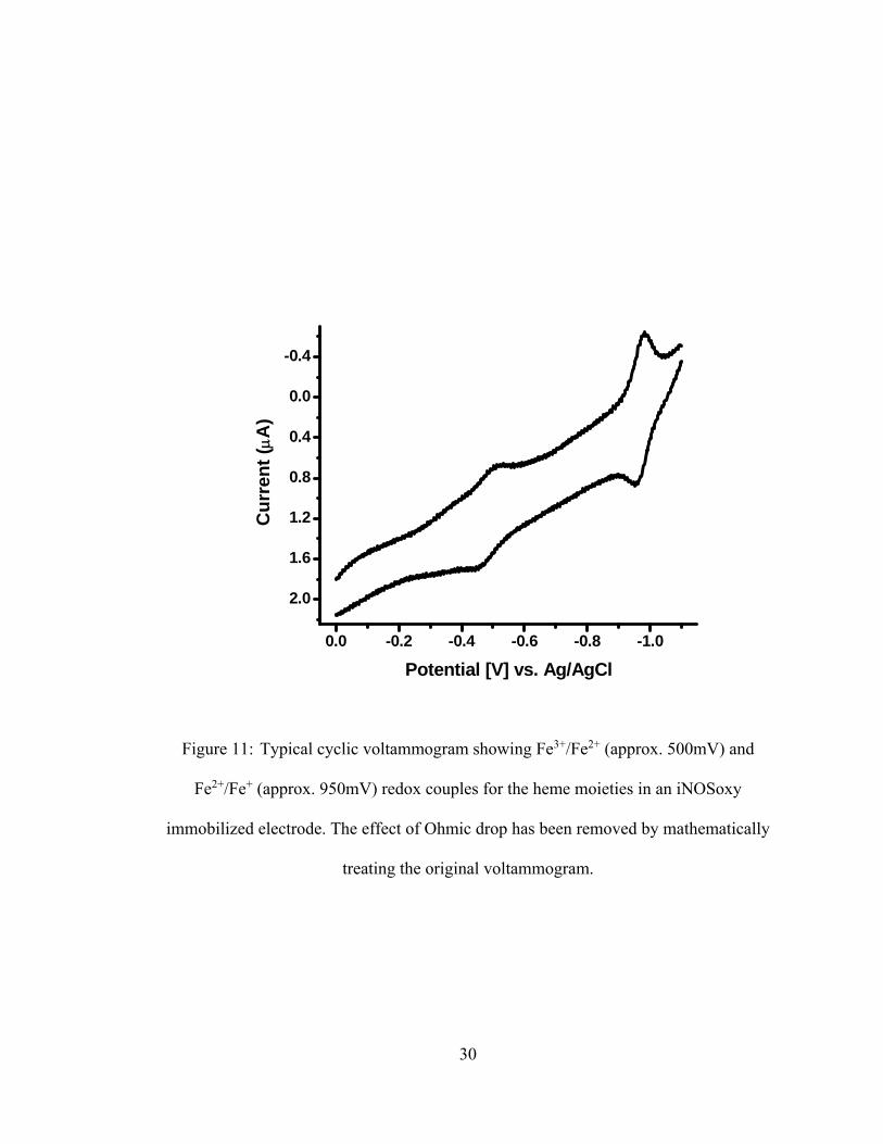
Figure 11: Typical cyclic voltammogram showing Fe3+/Fe2+ (approx. 500mV) and
Fe2+/Fe+ (approx. 950mV) redox couples for the heme moieties in an iNOSoxy
immobilized electrode. The effect of Ohmic drop has been removed by mathematically
treating the original voltammogram. ................................................................................. 30
Figure 12: Integrals of characteristic Fe3+ reduction in 8mV.s-1 linear sweep
voltammograms for iNOSoxy/PEI films adsorbed from iNOSoxy solution at pH 8.6 and
pH 7.0. ................................................................................................................... 32
Figure 13: Average of integrals of the characteristic Fe3+ reduction in 8mV.s-1 linear
sweep voltammograms showing different amounts of immobilization at different pH’s.
Standard deviation based on data for the same batch of electrodes immobilized at pH 8.6
and 7.0 (N=5). ................................................................................................................... 33
Figure 14: Cyclic voltammogram (200mV.s-1) for catalytic NO reduction by different
amounts of iNOSoxy immobilized at different pH’s measured at the same NO
concentration (120 μM). ................................................................................................... 35
Figure 15: Average catalytic peak current for NO reduction at the surfaces of
iNOSoxy/PEI modified electrodes prepared at pH 7.0 and pH 8.6. Standard deviation based
on data for the same batch of electrodes immobilized at the respective pH’s (N=5). ...... 38

xiv
Figure 16: Deconvoluted Amide I bands for the envelope signals obtained at pH 7.0
and pH 8.6 immobilization. .............................................................................................. 42
Figure 17: Deconvoluted Amide II bands for the envelope signals obtained at pH 7.0
and pH 8.6 immobilization. .............................................................................................. 43
Figure 18: Average cumulative NO concentration for immobilization pH values, pH
7.0 & pH 8.6; Standard deviation shown where N=3 for each immobilization pH. ......... 45
Figure 19: Average surface NO flux for each immobilization pH value; pH 7.0 & pH
8.6; Standard deviation shown where N=3 for each immobilization pH. ......................... 47
Figure 20: AFM images on the topology of the bare and PEI matrix adsorbed surfaces;
a) Bare HOPG (scan size 25 μm × 25 μm), b) PEI immobilized on HOPG for 5min (Scan
size: 25 μm × 25 μm). ....................................................................................................... 71
Figure 21: AFM images on the topology of the outermost layer in iNOSoxy
immobilization on PEI; a) Outermost NOS layer immobilized at pH 8.6 on linear PEI
matrix (Scan size: 1 μm × 1 μm) & b) Outermost NOS layer immobilized at pH 8.6 on
branched PEI matrix (Scan size: 1 μm × 1 μm). ............................................................... 72
Figure 22: Histographic comparison of cluster diameters for Figure 21 a) & 21 b)
showing number of features in each diameter range. ....................................................... 74
Figure 23: Average cumulative NO concentration generated from iNOSoxy/PEI films
using branched PEI and linear PEI. Error bars represent standard deviations for 5 trials. 76
Figure 24: Average surface flux of NO from iNOSoxy/PEI films immobilized on
branched PEI and linear PEI. Error bars represent standard deviations for 5 trials. ......... 78

xv
Figure 25: Typical cyclic voltammogram showing Fe3+/Fe2+ (approx. 500mV) and
Fe2+/Fe+ (approx. 950mV) redox couples for the heme moieties in an iNOSoxy
immobilized electrode. The effect of Ohmic drop has been removed by mathematically
treating the original graph. ................................................................................................ 80
Figure 26: Integrals of characteristic Fe3+ reduction in 8mV.s-1 linear sweep
voltammograms for iNOSoxy/PEI films adsorbed on linear PEI and branched PEI. Thin
films immobilized from iNOSoxy solution at pH 8.6. ...................................................... 82
Figure 27: Average of integrals of the characteristic Fe3+ reduction in 8mV.s-1 linear
sweep voltammograms for iNOSoxy/PEI films adsorbed on linear PEI and branched PEI.
Standard deviation based on data for the same batch of electrodes immobilized at pH 8.6
(N=5). ................................................................................................................... 83
Figure 28: Cyclic voltammogram (200 mV.s-1) for catalytic NO reduction iNOSoxy
immobilized on linear PEI and branched PEI, measured at the same NO concentration (120
μM). Immobilization pH is 8.6. ........................................................................................ 85
Figure 29: Average catalytic peak current for NO reduction at the surfaces of thin films
of iNOSoxy adsorbed at pH 8.6 onto linear PEI and branched PEI. Standard deviation
based on data for the same batch of electrodes immobilized using linear and branched PEI
(N=5). ................................................................................................................... 87
Figure 30: Structures of a) polycaprolactone, b) polyvinyl alcohol and, c) polyethyl-
vinyl acetate. ................................................................................................................... 98
Figure 31: A schematic representation of a typical electrospinning apparatus. ....... 101
Figure 32: Reaction scheme for the detection of NO by DAF-FM diacetate. .......... 107

xvi
Figure 33: Activity of iNOSoxy prior to electrospinning in three different
homogenized polymer/solvent mixtures and iNOSoxy. Control is provided by iNOSoxy
enzyme in EPPS buffer. Error bars represent standard deviations in repeated trials (N=3).
................................................................................................................. 109
Figure 34: A photograph of a section of PCL scaffold retrieved from the small 4 mm
mandrel immediately after electrospinning. Electrospinning conditions: Air-gap distance:
15 cm, Potential: 15 kV, Electrospinning emulsion ratio (v/v): 20:1 (Polymer mixture :
iNOSoxy containing buffer), Flow rate 1 ml/hr. ............................................................. 111
Figure 35: A photograph of a section of PEVA scaffold cut open and retrieved from
the small 4 mm mandrel after electrospinning. Electrospinning conditions: Air-gap
distance: 30 cm, Potential: 15 kV, Electrospinning emulsion ratio (v/v): 20:1 (Polymer
mixture : iNOSoxy containing buffer), Flow rate 3 ml/hr. ............................................. 111
Figure 36: A photograph of a section of PVA scaffold retrieved from the large mandrel
immediately after electrospinning. Electrospinning conditions: Air-gap distance: 15 cm,
Potential: 15 kV, Electrospinning emulsion ratio (v/v): 20:1 (Polymer mixture : iNOSoxy
containing buffer), Flow rate 1 ml/hr. ............................................................................. 112
Figure 37: Optical microscopic images of PCL microfibers stained with Sudan IV. ....
................................................................................................................. 114
Figure 38: Optical microscopic images of PCL microfibers with encapsulated pockets
of iNOSoxy. ................................................................................................................. 115
Figure 39: Fluorescence microscopic image of FITC stained PCL electrospun
microfibers. Electrospinning conditions: Air-gap distance: 15 cm, Potential: 15 kV,
xvii
Electrospinning emulsion ratio (v/v): 20:1 (Polymer mixture : iNOSoxy containing buffer),
Flow rate 1 ml/hr ............................................................................................................. 117
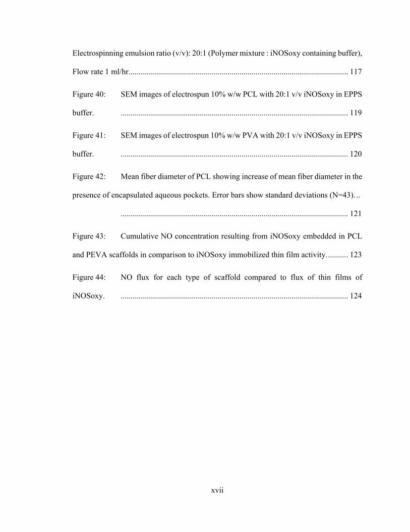
Figure 40: SEM images of electrospun 10% w/w PCL with 20:1 v/v iNOSoxy in EPPS
buffer. ................................................................................................................. 119
Figure 41: SEM images of electrospun 10% w/w PVA with 20:1 v/v iNOSoxy in EPPS
buffer. ................................................................................................................. 120
Figure 42: Mean fiber diameter of PCL showing increase of mean fiber diameter in the
presence of encapsulated aqueous pockets. Error bars show standard deviations (N=43). ..
................................................................................................................. 121
Figure 43: Cumulative NO concentration resulting from iNOSoxy embedded in PCL
and PEVA scaffolds in comparison to iNOSoxy immobilized thin film activity. .......... 123
Figure 44: NO flux for each type of scaffold compared to flux of thin films of
iNOSoxy. ................................................................................................................. 124

xviii
NOMENCLATURE
Amp: Ampicillin
AFM: Atomic force microscopy
ATR: Attenuated total reflectance
CaM: Calmodulin
CV: Cyclic voltammetry
δ-ALA: δ-Aminolevulinic acid
DI: De-ionized
DMSO: Dimethyl sulfoxide
DTT: Dithiothreitol
EPPS: 3-[4-(2-hydroxyethyl)piperazin-1-yl]propane-1-sulfonic acid
FAD: Flavin adenine dinucleotide
FE-SEM: Field emission scanning electron microscope
FITC: Fluorescein isothiocyanate
FMN: Flavin mononucleotide
FTIR: Fourier transform infrared spectroscopy
H4B: Tetrahydrobiopterin
xix
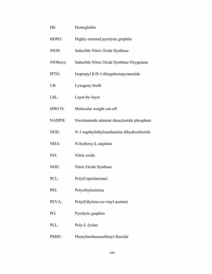
Hb: Hemoglobin
HOPG: Highly oriented pyrolytic graphite
iNOS: Inducible Nitric Oxide Synthase
iNOSoxy: Inducible Nitric Oxide Synthase Oxygenase
IPTG: Isopropyl β-D-1-thiogalactopyranoside
LB: Lysogeny broth
LbL: Layer-by-layer
MWCO: Molecular weight cut-off
NADPH: Nicotinamide adenine dinucleotide phosphate
NED: N-1-napthylethylenediamine dihydrochloride
NHA: N-hydroxy-L-arginine
NO: Nitric oxide
NOS: Nitric Oxide Synthase
PCL: Poly(Caprolactone)
PEI: Polyethylenimine
PEVA: Poly(Ethylene-co-vinyl acetate)
PG: Pyrolytic graphite
PLL: Poly-L-lysine
PMSF: Phenylmethanesulfonyl fluoride

xx
PVA: Polyvinyl alcohol
SEM: Scanning electron microscopy
SPIP®: Scanning probe image processor
TB: Terrific broth
UV-Vis: Ultraviolet – visible

1
GENERAL INTRODUCTION
Background
Increase of life expectancy is ascribed in part to the marked successes in the use of
medical implants. Diseases once considered untreatable make use of synthetic inserts for
better outcomes and are replacing or competing with surgical methods of intervention [1,
2]. Medical implants are becoming common practice in the treatment of acute to chronic
ailments, end-stage diseases, and post-traumatic surgeries. While the use of blood-
contacting medical implants increased over the past few decades [3], their lifespan and
inherent need for replacement has become a concern. Implant malfunction is presented as
clinical complications and can be life-threatening. One of the main causes needing surgical
replacement for a medical implant is the intrinsic thrombosis cascade on its surface that
causes it to be defective [4, 5]. For example, studies reveal that stent thrombosis in the
coronary artery result in 20-48% complications and death while 60-70% of the
cases studied resulted in myocardial infarction [6]. In other studies, control groups of
animals not administered with drugs showed thrombosis cascade on the luminal surfaces
of polyurethane grafts in contrast to sample population treated with potential suppressants
[7].

2
Thrombogenesis
All blood-contacting foreign-body surfaces are prone to a thrombosis cascade
regardless of surface properties [8, 9]. It involves both cellular and protein components.
Adsorption of fibrinogen onto the surface/s of the implant initiates the thrombosis cascade
followed by the recruitment of platelets [10-12], which presents a clinical complication, as
depicted in Figure 1.
Nitric oxide in antithrombogenic regimens
The success of implants that has a built-in antithrombogenic regimen such as in
drug-eluting stents has been reported previously [13-15]. A number of surface modification
methods are being used to increase the blood compatibility of blood-contacting implants
[16]. Release of an antithrombogenic chemical reagent is one approach that has been
adopted [6]. Nitric oxide (NO) is one such molecular intervention for maintaining vascular
hemostasis [17], that also exhibits direct inhibitory action on platelet aggregation [18].
Towards this end, direct NO release by NO donors such as S-nitrothiols [19] and N-
diazeniumdiolates [20] have been reported as potential routes for preparing NO-releasing
films that can be applied to blood-contacting implants.
However, NO releasing chemical coatings do not completely resolve the issue of
graft thrombosis. As shown by Figure 2, release coatings are a time-limited source of NO,
considering longer lifespan of most blood-contacting internal implants. Over a long period
of time, a depletion of NO source allows further recruitment of platelets and the thrombosis

3
cascade. The biocompatibility of direct chemical interventions is another common concern.
This work replaces chemically synthesized NO release coatings with layer-by-layer (LbL)
immobilized thin films of nitric oxide synthase (NOS) enzyme.

4
Figure 1: Scheme showing thrombosis at the surface of medical implant material.
Figure 2: A schematic representation of the depletion of NO source in a multilayer
release coating; a) at the initial stages, b) depletion over time.

5
Nitric oxide and nitric oxide synthase
Three NOS isoenzymes have been identified in mammals: inducible (iNOS/NOS-
2), neuronal (nNOS/ NOS-1), and endothelial (eNOS or NOS-3) [21]. As illustrated in
Figure 3, NOS convert L-arginine to citrulline and nitric oxide (NO) using nicotinamide
adenine dinucleotide phosphate (NADPH) as the reducing equivalent and oxygen [22-25].
The complete primary sequence for NOS [26] consists of an oxygenase domain (N-
terminus) and a reductase domain (C-terminus) with a linker having a calmodulin (CaM)
binding sequence [21]. Electron equivalents are transferred from the reductase domain to
the oxygenase domain where oxygen activation takes place. Following cofactors take part
in this transfer.
Flavin adenine dinucleotide (FAD) → Flavin mononucleotide (FMN) → heme → O2
Functional NOSs are dimeric; Cofactors FAD and FMN in the reductase domain of
one functional monomer transfers the electrons to the heme cofactor at the oxygenase
domain of the other functional monomer. Calcium ion (Ca2+) dependant calmodulin acts
as an activator switch for the transfer of the electrons from FMN to heme in nNOS and
eNOS but iNOS is independent of the Ca2+, likely due to its inherently tightly-bound CaM
[27].

6
L-arginine
Citrulline
Figure 3: A schematic representation of the general reaction catalyzed by NOS.
NH2
NH
NH
NH2
O
OH
NH2
O
NH
NH2
O
OH
+ O2
+ NO
NADPH + H+
NADP+

7
Figure 4: Reaction sequence in the reductase domain for the electron shunt; 1) NADPH2
to NADP, 2) FADH2 to FAD, 3) FMNH2 to FMN.
HH
OH
NH2
O
NO
O
OH
O-
O P
OH
NO
O
OH
O
O
O-
P
N
NN
NH2
H
OH
NH2
O
N+
OO
OH
O-
O P
OH
NO
O
OH
O
O
O-
P
N
NN
NH2H+ + 2e +
H
H
OH
O
OH OP
NO
O
OH
OO
OHP
N N
N
NH2
OHOH
OH
O
O
N
NNH
N
OH
O
OH OP
NO
O
OH
OO
OHP
N N
N
NH2
OHOH
OH
O
O
N
NNH
N
2H+ + 2e +
H
H
O
OH OP
OH
OHOH
OH
O
O
N
NNH
N
OH
O
OH OP
OHOH
OH
O
O
N
NNH
N
2H+ + 2e +
1)
2)
3)
-
-
-

8
Mechanism of nitric oxide mediated antithrombogenesis
The diffusion of NO into platelets stimulate guanylyl cyclase to produce cGMP that
in-turn lowers cytosolic Ca2+ concentration by the inhibition of gated Ca2+ channels [28].
Upon activation, calcium concentration in intracellular space of platelets rise from its
resting levels that triggers the cascade leading to platelet aggregation [29]. In the presence
of guanylyl cyclase inhibitors, the platelet aggregation increases significantly, providing
evidence to the regulatory function of NO on both cGMP and cGMP-dependant protein
kinases [30-33]. For fibrinogen binding, one of the essential requirements is the
conformational change of glycoprotein IIb/IIIa. The deactivation of phosphoinositide 3-
kinase suppresses this conformational change, resulting in fibrinogen binding [34], halting
the thrombosis cascade. Elevated levels of cAMP have also been linked to the decline in
levels of intracellular Ca2+ [35, 36]. NO-induced cGMP production could also suppress
protein kinase C, which in turn regulates surface expression of P-selectin, a mediator of
platelet adhesion [37].

9
Electrostatically adsorbed thin films of NOS enzyme
In our previous work published, we showed that, NO-based antithrombogenic
regimens that use blood-contacting LbL immobilized thin NOS enzyme films are better
than direct NO-release mechanisms in counteracting coagulation [38]. Adsorbed LbL onto
the surface as thin films, NOS catalyzes the conversion of substrate L-arginine to citrulline
and NO as shown in Figure 4.
Charge-based LbL adsorption of thin film components for biocompatible
applications have been widely explored [17, 18, 39, 40]. Here, the enzyme protein used is
a negatively charged polyelectrolyte in solution. Using this solution the enzyme is adsorbed
onto the positively charged matrix layer, polyethylenimine (PEI). Figure 5 and 6 are
depictions of the LbL concept as applicable to a single layer each of both matrix and active
component.

10
Figure 5: A schematic representation of a cross section of the LbL adsorbed monolayer
of NOS. Enzyme converts substrate to NO. Hence a NOS immobilized implant displays
intrinsic antithrombogenic activity.
Figure 6: A schematic representation of the LbL adsorbed monolayers of (-) charged
enzyme protein onto (+) charged polymer matrix layer on surface.
Implant / stent
Blood vessel
LbL adsorbed enzyme
Enzyme (protein) units [(‐)overall
charge]
PEI matrix
[(+) overall charge]

11
NOS embedded electrospun scaffolds
Inserts that demonstrate regenerative potential has been a recent area of thrust in
regenerative medicine. Scaffolds fabricated from synthetic material have been in use for
different applications from stem cell based transplantable artificial organs grown in
laboratory to drug delivery systems fabricated for pharmaceutical purposes. Electrospun
fiber scaffolds are known to closely resemble the extracellular matrix with the porosity and
ultra-thin fiber arrangements [41, 42]. A greater control over the tissue organization can be
achieved with electrospun fiber scaffolds and allows various functional modifications [43-
46].
Similar to all implantable material, scaffolds and mats are prone to the thrombosis
cascade on their surfaces and hence need a mechanism of antithrombogenesis. In this work,
we explore the use of functional iNOS embedded in electrospun fiber scaffolds as a
catalytic source of NO release for potential antithrombogenic action. Figure 7 is a
schematic representation of a porous microfiber with an encapsulated ‘node’ containing an
active component such as NOS. The porosity allows substrates and co-factors access to the
enzyme and allows NO release/diffusion.

12
Figure 7: A schematic representation of an embedded aqueous ‘node’ in an electrospun
scaffold microfiber.

13
NO as a short-lived reactive species and its significance in localized activity
As a gaseous molecule, nitric oxide is known to have a half-life ranging from 6-30
seconds [47]. However, nitric oxide does not have the ability to act as a circulating humoral
species under physiological conditions[48], because plasma hemoglobin (Hb) and
erythrocyte-based Hb scavenge NO rapidly [49]. NO flux resulting from an active NO-
releasing regimen of a modified medical implant is localized. In blood vessels, the NO flux
has to also compete with both the flow and scavengers in the blood plasma to maintain a
useful threshold level of NO in the local environment. Therefore it is reasonable to assume
that antithrombogenic activity of thin film coatings or drug-eluting scaffolds depend on
their ability to produce NO at a rate that compensates for the loss.

14
CHAPTER I: IMPROVED ENZYME LOADING IN LAYER-BY-LAYER (LbL)
ADSORBED THIN FILMS OF INDUCIBLE NITRIC OXIDE SYNTHASE (iNOS)
AND POLYETHYLENIMINE (PEI)
1.1 Introduction
This chapter describes the enzyme loading and activity of NOS enzyme in LbL thin
films. Our aim is to explore ways to increase the amount of enzyme loaded onto the active
layer. NO production is known both to inhibit platelet adhesion and to restore blood flow
[50]. Stimulated human endothelial cells are known to produce NO flux of 400 pmol.cm-
1.min-1 [51]. Our previous work accomplished this by exposing enzyme substrate to an LbL
deposited thin film consisting of multiple alternating iNOS and PEI layers. In this work,
we report comparable fluxes, achieved by an iNOSoxy monolayer immobilized on a
monolayer of PEI matrix. The catalytic turnover of substrate to NO is proportional to the
number of active enzyme units that are exposed to substrate molecules on the surface by
the modified surface. In the current work we explore methods to enhance enzyme loading

15
onto the outermost layer of LbL film of PEI/NOS. The pH at which the immobilization
takes place is expected to modulate the amount of NOS adsorbed. The Isoelectric point of
the enzyme plays a major role in deciding the correct pH of the buffer from which the
enzyme is adsorbed onto the thin film.
1.1.1 Isoelectric point of iNOS and its significance
The isoelectric point of mouse iNOS is 7.76 while for iNOSoxy domain it is 6.11
[52-54]. This implies that iNOSoxy protein used, carries an overall positive charge in
solution below pH 6.11. In contrast, at higher pH values of the solution, the protein has an
overall negative charge. We used two different pH’s, both above 6.11 which ensure the
protein is negatively charged, to study the levels of enzyme loading as a function of pH.
To this end, we used adjusted values of pH 8.6 and 7.0 for sample iNOSoxy
immobilizations. We avoided using pH in excess of 9.0, based on our preliminary findings
that showed enzyme denaturation effects with significantly low enzyme activity. The
control experiments used surfaces with only PEI immobilized. Similar work on pH-
dependant immobilization of proteins as functional thin films have been reported in various
other contexts [55].
16
1.2 Experimental
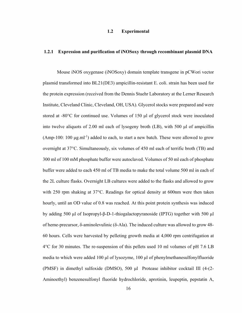
1.2.1 Expression and purification of iNOSoxy through recombinant plasmid DNA
Mouse iNOS oxygenase (iNOSoxy) domain template transgene in pCWori vector
plasmid transformed into BL21(DE3) ampicillin-resistant E. coli. strain has been used for
the protein expression (received from the Dennis Stuehr Laboratory at the Lerner Research
Institute, Cleveland Clinic, Cleveland, OH, USA). Glycerol stocks were prepared and were
stored at -80°C for continued use. Volumes of 150 μl of glycerol stock were inoculated
into twelve aliquots of 2.00 ml each of lysogeny broth (LB), with 500 μl of ampicillin
(Amp-100: 100 μg.ml-1) added to each, to start a new batch. These were allowed to grow
overnight at 37°C. Simultaneously, six volumes of 450 ml each of terrific broth (TB) and
300 ml of 100 mM phosphate buffer were autoclaved. Volumes of 50 ml each of phosphate
buffer were added to each 450 ml of TB media to make the total volume 500 ml in each of
the 2L culture flasks. Overnight LB cultures were added to the flasks and allowed to grow
with 250 rpm shaking at 37°C. Readings for optical density at 600nm were then taken
hourly, until an OD value of 0.8 was reached. At this point protein synthesis was induced
by adding 500 μl of Isopropyl-β-D-1-thiogalactopyranoside (IPTG) together with 500 μl
of heme-precursor, δ-aminolevulinic (δ-Ala). The induced culture was allowed to grow 48-
60 hours. Cells were harvested by pelleting growth media at 4,000 rpm centrifugation at
4°C for 30 minutes. The re-suspension of this pellets used 10 ml volumes of pH 7.6 LB
media to which were added 100 μl of lysozyme, 100 μl of phenylmethanesulfonylfluoride
(PMSF) in dimethyl sulfoxide (DMSO), 500 μl Protease inhibitor cocktail III (4-(2-
Aminoethyl) benzenesulfonyl fluoride hydrochloride, aprotinin, leupeptin, pepstatin A,
17
bestatin, and L-3-trans-Carboxyoxiran-2-carbonyl)-L-leucyl-agmatine), EMD Chemicals,
Inc., Gibbstown, NJ), 1 μl of DNase, and 10 μl of 1 M MgCl2. The resuspended cells were
lysed by sonication at 20 cycles each with 15 second ‘on’ and 45 second ‘off’ timing, while
the cell containing vials were being kept on ice. The light brown colored resuspended pellet
turned light pink indicating protein in the solution. Lysed cellular residue were separated
from the protein cocktail in solution by centrifugation at 12,000 rpm through 30 minutes
at 4°C. Protein in the lysate of the resultant supernatant was carefully collected. The
dissolved protein was salted-out to precipitate by adding a combined mass to the ratio of
0.3 g of ammonium sulfate ((NH4)2SO4(s)) per 1 ml of solution over a period of
approximately one hour while being stirred on ice. The precipitate was separated from the
supernatant by centrifugation at 10,000 rpm through 30 minutes at 4°C. We stored the
precipitated protein overnight and also confirmed its viability through several weeks of
storage.
The pellet saved at -80°C was re-suspended in base buffer to which 100 μl of PMSF
in DMSO and 100 μl of Protease inhibitor cocktail III were added. Resuspensions were
ultra-centrifuged at 10,000 rpm to further remove particulate debris that could clog the
affinity column. In a cold room maintained at 4°C, a newly packed affinity column [56,
57] of Ni-NTA superflow® (Qiagen Inc., CA) with a dead volume of 10 cm3 was charged
with 50 mM NiSO4 charge buffer followed by binding buffer. Once the protein suspension
was loaded, the Tris binding buffer followed by wash buffer were run through the column.
Finally, the elution buffer (200 mM imidazole) was used to detach and elute iNOSoxy,
observed by the gradual movement of reddish-brown colored band in the column. The
enzyme was collected in approx 0.5 ml aliquots in cryogenic vials. The used column was

18
stored in 25% ethanol after stripping. The protein aliquots were dialyzed in batches in 500
ml base buffer to which 200 μl β-mercaptoethanol was added. The enzyme containing
dialysis bags were transferred to fresh dialysis solution twice. The concentrated protein
aliquots were spot-frozen in cryogenic vials using liquid nitrogen before being stored at -
80°C. Concentration of protein in solution was determined for each batch before each
characterization method, using the bathochromic shift of the Soret band for the p-450 type
enzyme [58].
1.2.2 Adjustment of pH of protein in solution
Through a series of dilutions, a solution of ~12 μM NaOH(aq) was prepared. An
aliquot of 100 μl of iNOSoxy was thawed on ice and was transferred into a Microcon®
3000 MWCO centrifugal filter vial. To this tube, an aliquot of 400 μl of ~12 μM NaOH(aq)
was added. After vortexing for 3-5 seconds, the pH of the total aliquot was measured using
an Accumet mini pH probe connected to an AB-15 pH meter (Fisher Scientific). The
solution was centrifuged (in Beckman Coulter Microfuge-18 centrifuge) for 5 minutes at
14,000 rpm. After confirming approx. 4/5 in filtrate, the residual enzyme solution (approx.
100 μl) was kept on ice. This exchange sequence of the washing buffer was repeated three
times before the final aliquot of pH adjusted enzyme solution was retrieved. Using the mini
pH probe, the pH of the final 100 μl of enzyme aliquot was measured. Several aliquots of
100 μl each of pH adjusted enzyme solutions were made immediately before each
investigation.

19
1.2.3 Atomic force microscopic (AFM) imaging of adsorbed thin films
We used Agilent Pico-SPM atomic force microscope, PicoView controller and
Mac-mode module (Agilent Technologies Inc.). The scanner used in this imaging sequence
was the multi-purpose macro scanner with a scan range of 90 m in the x-y dimension and
7 m in the z-dimension (Agilent Technologies Inc.). PointProbe® Plus AFM probe
(NanoAndMore USA Inc., SC, USA) of 125 µm length, 30 µm width, 42 N/m spring
constant, and 270 kHz resonant frequencies were used in Acoustic AC mode. AFM
imaging was carried-out in a chamber at ambient conditions. We used grade ZYA highly
oriented pyrolytic graphite (HOPG) (Structure Probe Inc., PA, USA) for immobilization of
thin films. HOPG squares of 12 mm × 12 mm with 2 mm thickness were mounted on the
sample plate. Freshly cleaved bare HOPG surface was scanned at different speeds for scan
sizes ranging from 90 µm × 90 µm to focused scan sizes of 500 nm × 500 nm. Aliquots of
100 µl of 1.5 mg/ml PEI (Linear; MW 25,000 free base form; Polysciences Inc.) were
added onto the surfaces. After an incubation time of 5 minutes, the surface was washed
with DI water and dried in a nitrogen stream. Scan sizes ranging from 50 µm × 50 µm to
500 nm × 500 nm were obtained. Aliquots of 50 µl of iNOSoxy adjusted to pH 7.0 or 8.6
were added onto the PEI layer. After incubation for 5-10 minutes, the surface was washed
with EPPS buffer and dried using a nitrogen stream. AFM scans were performed for scan
areas ranging from 50 µm × 50 µm down to 500 nm × 500 nm.

20
1.2.4 Electrochemical investigation of heme-Fe3+ reduction and catalytic NO
reduction by LbL immobilized PEI/iNOSoxy films on graphite electrodes
We used an in-house purging system for making saturated NO in aqueous solution.
Nitric oxide (Praxair) was first purged through an oxygen-scrubbing alkaline pyrogallol
solution (1:4 v/v 250 mg.ml-1 pyrogallol: 1 g.ml-1 KOH). The resultant NO stream was then
purged through a saturated KOH solution for further removal of gaseous oxides. The
resultant pure NO gas stream was bubbled into 10 ml of DI water in a sealed scintillation
vial. Using a Griess assay calibration curve, the concentration of saturated aqueous NO
(2.0 mM) was established before each experiment for a separately purged saturated NO
(NO2-) solution.
We prepared graphite electrodes in-house following established methods [59]. The
electrodes were first polished using a rotating polishing pad. Then the discs were polished
using 0.3 μm and then with 0.05 μm size alumina with intermittent washings with water.
Each disc was sonicated in a water bath for 30 sec and dried in a stream of nitrogen gas.
Aliquots of 5 μl each of 1.5 mg/ml PEI solution (Linear; MW 25,000 free base form;
Polysciences Inc.) were added onto the polished surfaces of each of the discs. After a 10
minute incubation time, the electrodes were washed using DI water before drying in a
stream of nitrogen gas. Aliquots of 5 μl each of pH 7.0 and pH 8.6 enzyme solutions were
added on top of PEI-immobilized electrode surfaces. After a 15-20 minute incubation time,
the electrodes were washed with DI water and dried using a nitrogen gas stream. A typical
series of experiment uses five electrodes for enzyme immobilization, which we test side by
21
side for films prepared at pH 7.0 and pH 8.6 respectively. Three electrodes with only PEI
were used as the control experiment.
We used multi-necked electrochemical cells (Ace Glass). The working electrode is
the PEI/iNOSoxy modified PG electrode. We used Ag/AgCl as the reference electrode and
a platinum wire as an auxiliary electrode in 10.0 ml solution of the phosphate buffer. The
buffer was de-gased first for 30 minutes using a slow nitrogen gas flow. A nitrogen blanket
was maintained throughout the experiment. As the first step for all the electrodes, we
observed their current as a response to a linear sweep of potential in the absence of NO
substrate. Blank cyclic voltammetric scans are run to confirm the absence of interfering
catalytic currents for the reduction of nitrite derived from traces of NOx in solution. Small
aliquots of 2.0 mM NO were injected to the buffer solution using an airtight Hamilton
syringe. The NO concentration in buffer increased roughly by 20 μM increments. After
each injection, the solution was stirred using a magnetic stirrer before the beginning of
voltammetric scans.
1.2.5 Fourier Transform Infrared Spectroscopy (FTIR) on thin protein layers
We used attenuated total reflection (ATR) configuration in FTIR analysis to
investigate thin protein films. A diamond ATR crystal assembly (PIKE technologies) was
used with a Varian Digilab Scimitar series FTS 2000 FTIR. An aliquot of 100 μl of 1.5
mg/ml PEI (MW 25,000; Polysciences Inc.) was placed on the clean crystal. Using a plastic
microscope cover-slip the drop was smeared to cover the crystal. This was collected as the

22
blank reading. Evaporation of the water of the smear resulted in the PEI film on the crystal,
which we dried with a nitrogen gas stream using a portable nitrogen purge system. An
aliquot of 100 μl of enzyme solution adjusted at the desired pH was placed on the dry PEI
layer. After an incubation time of 15 minutes, the crystal was washed gently with DI water.
The resulting surface was dried under a slow nitrogen gas stream while obtaining IR
readings. The final IR reading was obtained for the immobilized layer after adding an
aliquot of 100 μl of EPPS buffer and resuspending the immobilized layer.
1.2.6 Griess assay for the determination of activity of thin films of PEI/iNOSoxy
Cylindrical discs were drilled-out from a block of high grade graphite using a hole-
saw type drill-bit. The discs were first polished using the same protocol described earlier
(section 1.2.4) for regular electrodes. Diameter of each disc was measured using a Vernier
caliper. Diameters are in the range of 7.27-7.35 mm for the seven discs used. Aliquots of
50 μl each of 1.5 mg/ml PEI solution (MW 25,000, Polysciences Inc.) were added onto the
polished surfaces of each disc. After a 5 minute incubation time, the disc surfaces were
thoroughly washed with DI water and were dried in a gentle nitrogen stream. Aliquots of
25 μl each of pH 7.0 enzyme solution were added on top of three PEI-modified disc
surfaces. Aliquots of 25 μl each of pH 8.6 enzyme solution were added on top of the other
three PEI-modified discs. One PEI modified disc was used as a control. Surfaces were
incubated for 15-20 minutes with the solutions of enzyme adjusted at the desired pH. After
incubation, the disc surfaces were thoroughly washed with DI water and dried in a gentle
nitrogen stream. All discs were placed in labeled vials with the modified surface faced up.

23
Volumes of 5 ml of the reaction cocktail containing 250 µM N-hydroxy-L-arginine (NHA),
10 µM tetrahydrobiopterin (H4B), and 400 µM dithiothreitol (DTT) prepared in 100 mM
phosphate buffer and adjusted to pH 7.4 were added to each of the vials. The reaction was
triggered by adding hydrogen peroxide to a final concentration of 150 mM at 37˚C.
Aliquots of 100 µl of reaction media were drawn at 2, 4, 8, 12, 24, 48 & 72 hour lapse
times, and were combined with 100 µl of each of Griess reagents R1 (sulfanilamide) and
R2 (N-(1-naphthyl)ethylenediamaine) (Cayman chemical company, Ann Arbor, MI, USA)
[60]. Spectrophotometric absorbance values for 540 nm against the reagent blank were
recorded (UV-Vis; Model 8543, Agilent Technologies) after a 10 minute reaction time for
all aliquots. A standard calibration series was prepared and the readings were plotted.

24
1.3 Results and discussion
1.3.1 AFM images of iNOSoxy on PEI-modified surfaces
Figure 8 shows topology of both the bare HOPG surface and PEI-modified HOPG
surface. Figure 8(a) shows the typical steps characteristic of a HOPG surface. Figure 8(b)
shows the AFM image of PEI immobilized on HOPG, and shows the arrangement of the
polymer aggregates on the surface. Figure 9 shows representative topological images of
PEI/iNOSoxy.

25
Figure 8: AFM images on the topology of the bare and PEI matrix adsorbed surfaces;
a) Bare HOPG (scan size 25 μm × 25 μm), b) PEI immobilized on HOPG for 5min (Scan
size: 25 μm × 25 μm).
(a)
(b)
5 μm
0
-22
19 nm
0
-22
19 nm
5 μm

26
Figure 9: AFM images with a 3-D perspective of the topology of the outermost layer in
iNOSoxy immobilization on PEI; a) Outermost iNOSoxy layer immobilized at pH 7.0
(a)
(b)

27
(Scan size: 1 μm × 1 μm), b) Outermost iNOSoxy layer immobilized at pH 8.6 (Scan
size: 1 μm × 1 μm).
Analysis of the prominent features in the 10-160 nm diameter range shows higher
density of protein clusters for PEI/iNOSoxy films made at pH 8.6 compared to films made
from pH 7.0 iNOSoxy solution. Figure 10 shows the comparative counts of the number of
protein clusters in various diameter ranges for films prepared from iNOSoxy at pH 7.0 and
pH 8.6.
An increased pH beyond the isoelectric point of iNOSoxy brings about a higher
negative charge density for iNOSoxy in the solution which drives higher electrostatic
loading of iNOSoxy on the positively charged PEI matrix. Lower pH values lead to less
attachment to the positively charged PEI film. AFM imaging and cluster density analysis
is consistent with higher enzyme loading at pH 8.6 compared to pH 7.0.

28
Figure 10: Histogram of cluster abundance in various diameter ranges for pH 8.6 and pH
7.0 PEI/iNOSoxy films.
10 t
o 2
0
20 t
o 3
0
30 t
o 4
0
40 t
o 5
0
50 t
o 6
0
60 t
o 7
0
70 t
o 8
0
80 t
o 9
0
90 t
o 1
00
100
to 1
10
110
to 1
20
120
to 1
30
130
to 1
40
140
to 1
50
0
4
8
12
16
Co
un
t (p
er
1m
2 )
Cluster diameter (nm)
iNOSoxy immobilized at pH 8.6 iNOSoxy immobilized at pH 7.0

29
1.3.2 Electrocatalytic reduction of NO mediated by iNOSoxy in films
Electrochemical analyses using iNOSoxy/PEI immobilized on electrode surfaces
as working electrodes provided two aspects of information. In the absence of substrate NO,
the redox active Fe3+-heme of iNOSoxy was used to monitor the overall amount of
iNOSoxy adsorbed in the two sets of films. Integration of the voltammetric current
provides the faradaic charge passed, which indicates the amount of iNOSoxy present in the
film. The enzyme iNOSoxy is also known to catalyze the electrochemical reduction NO
[61]. Therefore, in the second component of electrochemical characterization, we used this
metalloprotein-dependent catalytic reduction as a handle to compare and contrast activity
of iNOSoxy in the thin layers.
Figure 11 is a typical cyclic voltammogram for the specific window that shows the
Fe3+/Fe2+ and Fe2+/Fe+ redox couples by a heme moiety, iNOSoxy in this particular case.
In this control experiment the NO substrate is absent.
30
Figure 11: Typical cyclic voltammogram showing Fe3+/Fe2+ (approx. 500mV) and
Fe2+/Fe+ (approx. 950mV) redox couples for the heme moieties in an iNOSoxy
immobilized electrode. The effect of Ohmic drop has been removed by mathematically
treating the original voltammogram.
0.0 -0.2 -0.4 -0.6 -0.8 -1.0
2.0
1.6
1.2
0.8
0.4
0.0
-0.4
Cu
rren
t (
A)
Potential [V] vs. Ag/AgCl
31
1.3.2.1 iNOSoxy-heme Fe3+ reduction as a quantifier of immobilization
Integrals of voltammograms for Fe3+-heme reduction obtained at 8mV/s scan rate
linear sweep show higher faradaic charge transfer by electrodes modified with
PEI/iNOSoxy films where iNOSoxy solution maintained pH at 8.6 during immobilization.
PEI/iNOSoxy modified electrodes where immobilization of iNOSoxy solution maintained
pH at 7.0 show lower faradaic charge transfer. Figure 12 is a typical comparison of integrals
for a single electrode. Here the same electrode modified at pH 8.6 has more active sites per
unit surface area compared to pH 7.0.
In average, we find that films constructed using pH 8.6 iNOSoxy solution exhibit
close to 4x the amount of charge compared to films constructed using pH 7.0 iNOSoxy
solution (55 nC for pH 8.6 versus 14 nC for pH 7.0) as shown in Figure 13. This translates
to an average of 0.57 pmol of iNOSoxy adsorbed in films constructed at pH 8.6 compared
to 0.15 pmol of iNOSoxy in films formed at pH 7.0.

32
Figure 12: Integrals of characteristic Fe3+ reduction in 8mV.s-1 linear sweep
voltammograms for iNOSoxy/PEI films adsorbed from iNOSoxy solution at pH 8.6 and
pH 7.0.
-0.2 -0.3 -0.4 -0.5 -0.6 -0.7 -0.8 -0.90
50
100
150
200
250
300
Ab
solu
te c
urr
ent
valu
e (n
C)
Potential [V] vs. Ag/AgCl
Film immobilized at pH 8.6 Film immobilized at pH 7.0

33
Figure 13: Average of integrals of the characteristic Fe3+ reduction in 8mV.s-1 linear
sweep voltammograms showing different amounts of immobilization at different pH’s.
Standard deviation based on data for the same batch of electrodes immobilized at pH 8.6
and 7.0 (N=5).
0 5 10 15 20 25 30 35 40 45 50 55 60 65 70 75 80
0
5
10
15
20
25
30
35
40
45
50
55
60
65 Film immobilized at pH 8.6 Film immobilized at pH 7.0
Time (Sec)
To
tal c
har
ge
tran
sfer
(n
C)

34
1.3.2.2 Catalytic reduction of NO mediated by iNOSoxy on PEI/iNOSoxy films on
PG electrodes
Addition of NO substrate to the solution results in a catalytic peak around -0.9V vs.
Ag/AgCl. As expected based on previous studies [38, 61], the catalytic current is
proportional to NO concentration. Figure 14 shows the peaks of nitric oxide catalytic
reduction mediated by iNOSoxy for pH 8.6 and pH 7.0 films.

35
Figure 14: Cyclic voltammogram (200mV.s-1) for catalytic NO reduction by different
amounts of iNOSoxy immobilized at different pH’s measured at the same NO
concentration (120 μM).
0.2 0.0 -0.2 -0.4 -0.6 -0.8 -1.0 -1.2
-2
0
2
4
6
8
10 PG electrode with iNOSoxy immobilized at pH 8.6
PG electrode with iNOSoxy immobilized at pH 7.0
Blank: PEI only
Cu
rre
nt
(A
)
Potential [V] vs. Ag/AgCl
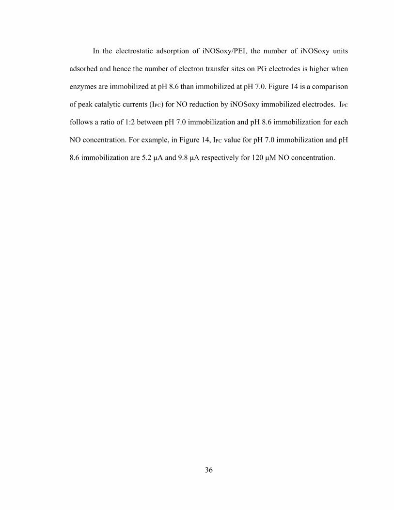
36
In the electrostatic adsorption of iNOSoxy/PEI, the number of iNOSoxy units
adsorbed and hence the number of electron transfer sites on PG electrodes is higher when
enzymes are immobilized at pH 8.6 than immobilized at pH 7.0. Figure 14 is a comparison
of peak catalytic currents (IPC) for NO reduction by iNOSoxy immobilized electrodes. IPC
follows a ratio of 1:2 between pH 7.0 immobilization and pH 8.6 immobilization for each
NO concentration. For example, in Figure 14, IPC value for pH 7.0 immobilization and pH
8.6 immobilization are 5.2 μA and 9.8 μA respectively for 120 μM NO concentration.

37
1.3.2.3 Michaelis-Menten kinetics
The rate of an enzyme-catalyzed reaction is given as V in the Michaelis-Menten
model where;
V ⨉
(1.1)
VMax is the maximum rate at which substrate turnover takes place, kM is the
substrate concentration at half maximum of the rate of reaction (also known as the
Michaelis constant), and, kcat is the turnover number. The corresponding electrochemical
version of the Michaelis-Menten equation is as follows;
I ⨉
(1.2)
where the rate of catalysis is represented by the catalytic current Icat. In this
equation, Γ is the active surface catalyst concentration, A is the electrode surface area, and
F is the Faraday constant. The rearrangement allows the plotting of normalized catalytic
current against nitric oxide concentration as shown in Figure 15, where typical enzyme
saturation kinetics are observed.
38
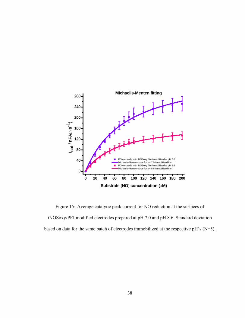
Figure 15: Average catalytic peak current for NO reduction at the surfaces of
iNOSoxy/PEI modified electrodes prepared at pH 7.0 and pH 8.6. Standard deviation
based on data for the same batch of electrodes immobilized at the respective pH’s (N=5).
0 20 40 60 80 100 120 140 160 180 200
0
40
80
120
160
200
240
280Michaelis-Menten fitting
PG electrode with iNOSoxy film immobilized at pH 7.0 Michaelis-Menton curve for pH 7.0 immobilized film PG electrode with iNOSoxy film immobilized at pH 8.6 Michaelis-Menton curve for pH 8.6 immobilized film
Substrate [NO] concentration (M)
I ca
t / n
FAs
-1)
0
5
10
15
20
25
30
35
% (
?Y)

39
iNOSoxy/PEI films grown at pH 7.0 show higher turnover rates of iNOSoxy-
mediated NO reduction compared to films formed at pH 8.6. Non-linear fitting of observed
traces using the Michaelis-Menten kinetic model yields the kM and kcat values for the two
films.
pH of iNOSoxy at Immobilization
kM (μM) kcat (s‐1)
pH 8.6 69.6±4.8 184.4±5.3
pH 7.0 85.9±7.4 375.2±14.6
Table 1: Extracted Michaelis-Menten parameters from nonlinear regression fitting
using Michaelis-Menten model.
According to the Michaelis-Menten parameters extracted from nonlinear fitting of
experimental data, a marked difference of the rate of catalysis is observed between the two
types of iNOSoxy films. Films immobilized at pH 7.0 exhibit higher catalytic turnovers
compared to films immobilized at pH 8.6. The differences in the electrochemical turnover
numbers for iNOSoxy-mediated NO catalytic reduction may be related to a pH-dependent
structural change in the enzyme protein.
Dynamic motions which depend on structure of an enzyme protein are known to
play a role in enzyme catalysis [62-65]. In our case, iNOSoxy electrostatically adsorbed at
the two different pH’s may adopt different active structures characterized by distinct

40
catalytic properties. The structural distortion changes the dynamic motions of the enzyme
as reported in literature [66-70]. The degree to which the pH potentially affected the
iNOSoxy structure, and thus its catalytic properties may be explored in terms of close
structural characterization of PEI/iNOSoxy films prepared at various pH’s.
1.3.3 FTIR Characterization of PEI/iNOSoxy films prepared at various pH’s
FTIR has been used as a tool to investigate conformational change on protein
microenvironments [71, 72]. For example, works by Korkmaz-Ozkan and co-workers [71]
on the outer membrane protein-G (Omp-G) of E.Coli., discusses how similar pH-induced
conformational changes can be monitored by FTIR. We looked closely at structural
features of iNOSoxy/PEI thin films using FTIR spectroscopy. Amide I (1650 cm-1) and
amide II (1550 cm-1) bands [73-75] provide good structural handles to monitor local
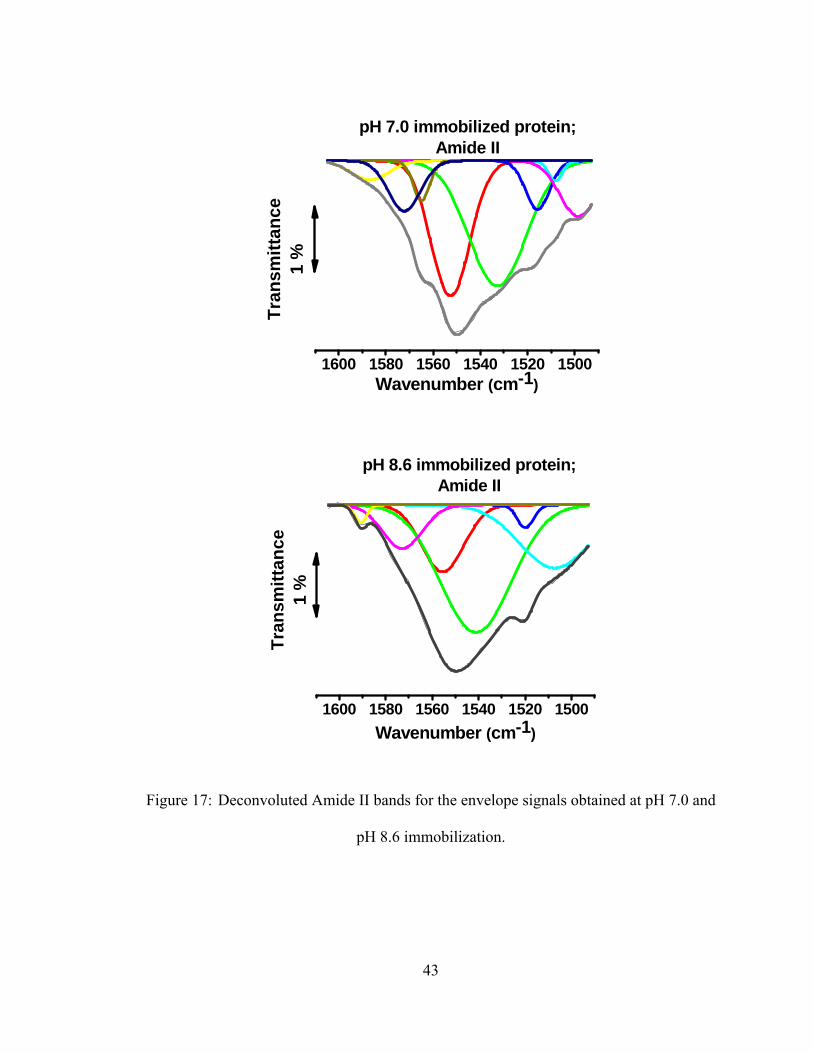
changes in the tertiary structure [62-64]. Figure 16 and Figure 17 show the amide I and II
envelopes of iNOSoxy on PEI in films formed at pH 7.0 and pH 8.6. The Figures also show
the deconvolution of the amide bands into individual components contributing to the
overall envelopes.
Deconvolution of amide I and amide II bands of iNOSoxy into different component
peaks suggest different microenvironments of the enzyme when deposited at different pH.
Solution pH is known to induce conformational changes in proteins [72, 76-78], and
enzymes [68, 79]. Significant differences in both the wavenumber and in the intensity of
component peaks are evident as shown in Figure 16 and Figure 17. The observed changes
in both number of components and positions in amide I and II FTIR envelopes is probably

41
the result of changes in the tertiary structure of iNOSoxy when adsorbed from solution at
pH 8.6 as opposed to pH 7.0 [62-64].
Change of pH is expected to result in changes in intra-molecular hydrogen bonds
and other bipolar interactions. This may drive distortions in the protein’s 3D structure. pH-
driven protein conformational changes are not new, and have been reported for several
proteins [72, 76-78] and enzymes [71, 72, 80, 81]. Dirix and co-workers [82] have
interpreted deconvolution of amide I FTIR envelope into six peaks and attributed them to
structural components such as α & β helices, extended chains, turns and bends. The work
of Baron [73] attributes deconvoluted FTIR peaks to secondary structures in a specific
example where enzyme catalysis is explained. The close link of protein conformation and
enzyme catalysis has been studied both in their native environments [68, 69] and in
immobilized films [20, 78].
From our results, we find pH 7.0 immobilization to result in an iNOSoxy/PEI film
with a higher rate of catalysis than films prepared at pH 8.6, despite high enzyme loading
at pH 8.6. This suggests that immobilization at pH 7.0 brings about a three dimensional
enzyme structure with high catalytic efficiency compared to enzyme units adsorbed at pH
8.6.

42
Figure 16: Deconvoluted Amide I bands for the envelope signals obtained at pH 7.0
and pH 8.6 immobilization.
1720 1700 1680 1660 1640 1620 1600
Tra
nsm
itta
nce
1 %
pH 7.0 immobilized protein;Amide I band
Wavenumber (cm-1)
1720 1700 1680 1660 1640 1620 1600
Tra
nsm
itta
nce
1 %
pH 8.6 immobilized protein;Amide I
Wavenumber (cm-1)
43
Figure 17: Deconvoluted Amide II bands for the envelope signals obtained at pH 7.0 and
pH 8.6 immobilization.
1600 1580 1560 1540 1520 1500
Tra
nsm
itta
nce
1 %
Wavenumber (cm-1)
pH 7.0 immobilized protein;Amide II
1600 1580 1560 1540 1520 1500
Tra
ns
mit
tan
ce
1 %
pH 8.6 immobilized protein;Amide II
Wavenumber (cm-1)

44
1.3.4 Activity of iNOSoxy / PEI thin films
The ultimate test for iNOSoxy-based thin films is the catalytic synthesis of NO
when ingredients of the NOS reaction are provided. We thus explored whether the NOS
reaction in thin films is affected by the pH at which iNOSoxy is adsorbed onto PEI layer.
To this end, we measured NO generated over time in a cocktail that contains the N-
hydroxy-L-arginine as a substrate surrogate and all other ingredients of the NOS reaction
[83, 84]. We followed NO synthesis in terms of nitrite accumulated in solution. In aqueous
media the NOS reaction product, NO, converts to nitrite, and the latter is typically used as
measure of NO formation [60]. Since the reaction cocktail contains all factors for the NOS
catalytic turnover, the initiation of the reaction is the immersion of iNOSoxy-modified
surfaces in the reaction cocktail. Figure 18 shows the graph of cumulative NO synthesis in
the reaction cocktail measured from the time of immersion. NO accumulation is rapid in
the beginning, and reaches a plateau after about 48 hours. For example, during the second
two-hour window the cumulative NO concentration almost quadruples (approx. 0.5 to 2.1
μM for films immobilized at pH 7.0 and 1.3 to 4.5 μM for films immobilized at pH 8.6).
In contrast, in the following four-hour window the cumulative NO concentration increases
only to below twofold of the preceding value, eventually reaching a plateau after 48 hours.
However, as evident from the same Figure, the average cumulative concentration at each
sample interval resulting from pH 8.6 PEI/iNOSoxy film activity is two- to three-fold that
of the average cumulative concentration resulting from activity of the pH 7.0 thin film. At
72 hours, thin layers immobilized at pH 8.6 resulted in nearly 60 nmol of NO released in
solution, whereas thin layers immobilized at pH 7.0 resulted in just over 20 nmol of NO
released.

45
Figure 18: Average cumulative NO concentration for immobilization pH values, pH 7.0
& pH 8.6; Standard deviation shown where N=3 for each immobilization pH.
2hrs 4hrs 8hrs 12hrs 24hrs 48hrs 72hrs
0123456789
1011121314 Blank: PEI immobilized PG discs
iNOSoxy immobilized at pH 7.0 iNOSoxy immobilized at pH 8.6
Cu
mu
lati
ve [
NO
] (
M)
Time

46
When converted to the average flux per unit surface area of the immobilized
surfaces, our results show an initial burst of NO through the first 12 hours followed by a
decline and then stable NO release up to the end of our observation window of 72 hours
for all PEI/iNOSoxy surfaces regardless of pH of film formation (Figure 19). This two-
phase NO release kinetics model has been previously reported [85, 86]. The initial burst is
especially useful to counter early prosthetic graft occlusion and hence delay the
requirement of surgical revision of synthetic grafts such as those used in hemodialysis [87].
The flux peaks at a 2-4 hour timeframe from the start of the reaction. The average peak NO
flux values range from 386 pmol.mm-2 for discs incubated using protein at pH 8.6 to 194
pmol.mm-2 for discs incubated using protein at pH 7.0 in the same time window. For the
two hour window considered, this translates to nearly 322 pmol.cm-2.min-1 for discs
incubated using protein at pH 8.6 and to nearly 162 pmol.cm-2.min-1 for discs incubated
using protein at pH 7.0. The NO flux resulting from the single enzyme layer immobilized
at pH 8.6 comes close to the NO flux of stimulated human endothelial cells, at around 400
pmol.cm-2.min-1 [51]. Moreover, the average flux resulting from pH 7.0 immobilized films
diminishes faster, while flux resulting from pH 8.6 immobilized films is sustained at a
higher level of release up until the end of our observation window of 72 hours.

47
Figure 19: Average surface NO flux for each immobilization pH value; pH 7.0 & pH 8.6;
Standard deviation shown where N=3 for each immobilization pH.
0-2 2-4 4-8 8-12 12-24 24-48 48-720
50
100
150
200
250
300
350
400
450 Blank: PEI immobilized PG discs iNOSoxy immobilized at pH 7.0 iNOSoxy immobilized at pH 8.6
NO
flu
x (p
mo
l/m
m2 )
Time period (hours)

48
1.4 Conclusion
This chapter describes an improvement in the LbL method for the fabrication of
thin films containing NOS enzymes for potential enzyme-based NI-release coatings. NOS
enzymes can potentially be used in antithrombogenic coatings on blood-contacting medical
implants. We have used pH to modulate the iNOSoxy loading on PEI layers. We report an
increase of activity of the thin films formed at pH 8.6 compared to thin films built at pH
7.0 based on NO flux values. The activity of a LbL immobilized enzyme monolayer
adsorbed at pH 8.6 is comparable to reported activity resulting from alternating (3)NOS-
(3)PEI multilayer thin film, that was immobilized at pH 7.4.
The specific focus of this work has been to explore the use of pH of the
immobilizing solution used to adsorb NOS enzyme layer to optimize enzyme loading on
PEI. Electrochemical analysis of iNOSoxy films showed a high density of enzyme in films
prepared at pH 8.6 compared to pH 7.0. This is consistent with our AFM imaging analyses,
which show higher cluster density of features adsorbed at pH 8.6. The immobilization pH
therefore controls the iNOSoxy loading on PEI thin films and hence the higher NO flux
observed for films prepared at pH 8.6.

49
1.5 Reference
1. Taggart, D.P., Stents or surgery in coronary artery disease in 2013. Annals of
Cardiothoracic Surgery, 2013. 2(4): p. 431-434.
2. Serruys, P.W., M.C. Morice, A.P. Kappetein, A. Colombo, D.R. Holmes, M.J.
Mack, E. Stahle, T.E. Feldman, M. van den Brand, E.J. Bass, N. Van Dyck, K.
Leadley, K.D. Dawkins, and F.W. Mohr, Percutaneous coronary intervention
versus coronary-artery bypass grafting for severe coronary artery disease. N Engl
J Med, 2009. 360(10): p. 961-72.
3. Moss, A.J., Hamburger, S., Moore, R.M., Jeng, L.L., Howie, L.J., Use of selected
medical device implants in the United States, 1988. Advance data from vital and
health statistics, Feb 26, 1991. 191: p. 1-24.
4. Baim, D.S., Carrozza Jr, J.P., Stent thrombosis; closing in on the best preventive
treatment. Circulation, 1997. 95(5): p. 1098-1100.
5. Rasche, H., Haemostasis and thrombosis: an overview. European Heart Journal
Supplements, 2001. 3(Q): p. Q3-Q7.
6. Iakovou, I., Thrombosis after stent implantation: How much of a problem is there?
Future Cardiology, 2008. 4(3): p. 261-267.
7. Matsumoto, M., T. Ban, and Y. Okamoto, Behavior of platelets and leukocytes on
the luminal surface of small caliber polyurethane grafts. J Cardiovasc Surg
(Torino), 1989. 30(4): p. 609-13.

50
8. van Kampen, C.L. and D.F. Gibbons, Effect of implant surface chemistry upon
arterial thrombosis. J Biomed Mater Res, 1979. 13(4): p. 517-41.
9. Sarkar, S., K.M. Sales, G. Hamilton, and A.M. Seifalian, Addressing
thrombogenicity in vascular graft construction. J Biomed Mater Res B Appl
Biomater, 2007. 82(1): p. 100-8.
10. Frost, M., Meyerhoff, M.E., Sensors: Tackling biocompatibility. Analytical
Chemistry, 2006. 78(1): p. 7370-7377.
11. Alkhamis, T.M., Beissinger, R.L., Chediak, J.R., Artificial surface effect on red
blood cells and platelets in laminar shear flow. Blood, 1990. 75(7): p. 1568-1575.
12. Furie, B. and B.C. Furie, Thrombus formation in vivo. J Clin Invest, 2005. 115(12):
p. 3355-62.
13. Urban, P., A. Abizaid, A. Banning, A.L. Bartorelli, A.C. Baux, V. Dzavik, S. Ellis,
R. Gao, D. Holmes, M.H. Jeong, V. Legrand, F.J. Neumann, M. Nyakern, C.
Spaulding, and S. Worthley, Stent thrombosis and bleeding complications after
implantation of sirolimus-eluting coronary stents in an unselected worldwide
population: a report from the e-SELECT (Multi-Center Post-Market Surveillance)
registry. J Am Coll Cardiol, 2011. 57(13): p. 1445-54.
14. Hanna, N.N., M.A. Gaglia, Jr., R. Torguson, I. Ben-Dor, M.A. Gonzalez, S.D.
Collins, A.I. Syed, G. Maluenda, K. Kaneshige, Z. Xue, L.F. Satler, K.M. Kent,
W.O. Suddath, A.D. Pichard, and R. Waksman, Three-year outcomes following
sirolimus- versus paclitaxel-eluting stent implantation in an unselected population

51
with coronary artery disease (from the REWARDS Registry). Am J Cardiol, 2010.
106(4): p. 504-10.
15. Di Lorenzo, E., R. Sauro, A. Varricchio, G. Carbone, G. Cortese, M. Capasso, T.
Lanzillo, F. Manganelli, C. Mariello, F. Siano, M.R. Pagliuca, G. Stanco, G.
Rosato, and G. De Luca, Long-Term outcome of drug-eluting stents compared with
bare metal stents in ST-segment elevation myocardial infarction: results of the
paclitaxel- or sirolimus-eluting stent versus bare metal stent in Primary
Angioplasty (PASEO) Randomized Trial. Circulation, 2009. 120(11): p. 964-72.
16. Jacobs, H., D. Grainger, T. Okano, and S.W. Kim, Surface modification for
improved blood compatibility. Artif Organs, 1988. 12(6): p. 506-7.
17. Walford, G., Locallzo, J., Nitric oxide in vascular biology. Journal of Thrombosis
and Haemostasis, 2003. 1(10): p. 2112-2118.
18. Ignarro, L.J., Biological actions and properties of endothelium-derived nitric oxide
formed and released from artery and vein. Circulation Research, 1989. 65(1): p. 1-
21.
19. Jourd'heuil, D., Hallen, K., Feelisch, M., Grisham, M.B., Dynamic state of S-
nitrosothiols in human plasma and whole blood. Free Radical Biology & Medicine,
2000. 28(3): p. 409-417.
20. Zhang, H., Annich, G.M., Miskulin, J., Stankiewicz, K., Osterholzer, K., Merz, S.I.,
Bartlett, R.H., Meyerhoff, M.E., Nitric oxide releasing fumed silica particles:
Synthesis, characterization, and biomedical application. Journal of the American
Chemical Society, 2003. 125(17): p. 5015-5024.

52
21. Titheradge, M.A., Nitric oxide protocols. Methods in molecular biology. 1998,
Totowa, N.J.: Humana Press. xi, 324 p.
22. Stuehr, D.J., N.S. Kwon, C.F. Nathan, O.W. Griffith, P.L. Feldman, and J.
Wiseman, N omega-hydroxy-L-arginine is an intermediate in the biosynthesis of
nitric oxide from L-arginine. J Biol Chem, 1991. 266(10): p. 6259-63.
23. Kwon, N.S., C.F. Nathan, C. Gilker, O.W. Griffith, D.E. Matthews, and D.J. Stuehr,
L-citrulline production from L-arginine by macrophage nitric oxide synthase. The
ureido oxygen derives from dioxygen. J Biol Chem, 1990. 265(23): p. 13442-5.
24. Mayer, B., M. John, B. Heinzel, E.R. Werner, H. Wachter, G. Schultz, and E.
Bohme, Brain nitric oxide synthase is a biopterin- and flavin-containing multi-
functional oxido-reductase. FEBS Lett, 1991. 288(1-2): p. 187-91.
25. Klatt, P., K. Schmidt, G. Uray, and B. Mayer, Multiple catalytic functions of brain
nitric oxide synthase. Biochemical characterization, cofactor-requirement, and the
role of N omega-hydroxy-L-arginine as an intermediate. J Biol Chem, 1993.
268(20): p. 14781-7.
26. Bredt, D.S., P.M. Hwang, C.E. Glatt, C. Lowenstein, R.R. Reed, and S.H. Snyder,
Cloned and expressed nitric oxide synthase structurally resembles cytochrome P-
450 reductase. Nature, 1991. 351(6329): p. 714-8.
27. Cho, H.J., Q.W. Xie, J. Calaycay, R.A. Mumford, K.M. Swiderek, T.D. Lee, and
C. Nathan, Calmodulin is a subunit of nitric oxide synthase from macrophages. J
Exp Med, 1992. 176(2): p. 599-604.

53
28. Trepakova, E.S., R.A. Cohen, and V.M. Bolotina, Nitric oxide inhibits capacitative
cation influx in human platelets by promoting sarcoplasmic/endoplasmic reticulum
Ca2+-ATPase-dependent refilling of Ca2+ stores. Circ Res, 1999. 84(2): p. 201-9.
29. Kroll, M.H. and A.I. Schafer, Biochemical mechanisms of platelet activation.
Blood, 1989. 74(4): p. 1181-95.
30. Moro, M.A., R.J. Russel, S. Cellek, I. Lizasoain, Y. Su, V.M. Darley-Usmar, M.W.
Radomski, and S. Moncada, cGMP mediates the vascular and platelet actions of
nitric oxide: confirmation using an inhibitor of the soluble guanylyl cyclase. Proc
Natl Acad Sci U S A, 1996. 93(4): p. 1480-5.
31. Rao, G.H., S. Krishnamurthi, L. Raij, and J.G. White, Influence of nitric oxide on
agonist-mediated calcium mobilization in platelets. Biochem Med Metab Biol,
1990. 43(3): p. 271-5.
32. Pigazzi, A., S. Heydrick, F. Folli, S. Benoit, A. Michelson, and J. Loscalzo, Nitric
oxide inhibits thrombin receptor-activating peptide-induced phosphoinositide 3-
kinase activity in human platelets. J Biol Chem, 1999. 274(20): p. 14368-75.
33. Zhang, J., J. Zhang, S.J. Shattil, M.C. Cunningham, and S.E. Rittenhouse,
Phosphoinositide 3-kinase gamma and p85/phosphoinositide 3-kinase in platelets.
Relative activation by thrombin receptor or beta-phorbol myristate acetate and
roles in promoting the ligand-binding function of alphaIIbbeta3 integrin. J Biol
Chem, 1996. 271(11): p. 6265-72.
54
34. Michelson, A.D., S.E. Benoit, M.I. Furman, W.L. Breckwoldt, M.J. Rohrer, M.R.
Barnard, and J. Loscalzo, Effects of nitric oxide/EDRF on platelet surface
glycoproteins. Am J Physiol, 1996. 270(5 Pt 2): p. H1640-8.
35. Geiger, J., C. Nolte, and U. Walter, Regulation of calcium mobilization and entry
in human platelets by endothelium-derived factors. Am J Physiol, 1994. 267(1 Pt
1): p. C236-44.
36. Fischer, T.H. and G.C. White, 2nd, Partial purification and characterization of
thrombolamban, a 22,000 dalton cAMP-dependent protein kinase substrate in
platelets. Biochem Biophys Res Commun, 1987. 149(2): p. 700-6.
37. Murohara, T., S.J. Parkinson, S.A. Waldman, and A.M. Lefer, Inhibition of nitric
oxide biosynthesis promotes P-selectin expression in platelets. Role of protein
kinase C. Arterioscler Thromb Vasc Biol, 1995. 15(11): p. 2068-75.
38. Bayachou, M., Abou-Diwan, C. , US Patent # 2009/073643. 2009.
39. Freedman, J.E., Localzo, J., Barnard, M.R., Alpert, C., Keany, J.F., Michelson,
A.D., Nitric oxide released from activated platelets inhibits platelet recruitment.
Journal of Clinical Investigation, 1997. 100(2): p. 350-356.
40. Smith, A.W., Biofilms and antibiotic therapy: Is there a role for combating
bacterial resistance by the use of novel drug delivery systems? Advanced Drug
Delivery Reviews, 2005. 57(10).
41. Kenawy, E., G.L. Bowlin, K. Mansfield, J. Layman, D.G. Simpson, E.H. Sanders,
and G.E. Wnek, Release of tetracycline hydrochloride from electrospun

55
poly(ethylene-co-vinylacetate), poly(lactic acid), and a blend. Journal of
Controlled Release, 2002. 81(1–2): p. 57-64.
42. Telemeco, T.A., C. Ayres, G.L. Bowlin, G.E. Wnek, E.D. Boland, N. Cohen, C.M.
Baumgarten, J. Mathews, and D.G. Simpson, Regulation of cellular infiltration into
tissue engineering scaffolds composed of submicron diameter fibrils produced by
electrospinning. Acta Biomater, 2005. 1(4): p. 377-85.
43. Sun, T., S. Mai, D. Norton, J.W. Haycock, A.J. Ryan, and S. MacNeil, Self-
organization of skin cells in three-dimensional electrospun polystyrene scaffolds.
Tissue Eng, 2005. 11(7-8): p. 1023-33.
44. Lyu, S., C. Huang, H. Yang, and X. Zhang, Electrospun fibers as a scaffolding
platform for bone tissue repair. J Orthop Res, 2013. 31(9): p. 1382-9.
45. Wang, H.S., G.D. Fu, and X.S. Li, Functional polymeric nanofibers from
electrospinning. Recent Pat Nanotechnol, 2009. 3(1): p. 21-31.
46. Wang, X., B. Ding, and B. Li, Biomimetic electrospun nanofibrous structures for
tissue engineering. Materials Today, 2013. 16(6): p. 229-241.
47. Palmer, R.M.J., D.S. Ashton, and S. Moncada, Vascular endothelial-cells
synthesize nitric-oxide from L-arginine. Nature, 1988. 333(6174): p. 664-666.
48. Hakim, T.S., K. Sugimori, E.M. Camporesi, and G. Anderson, Half-life of nitric
oxide in aqueous solutions with and without haemoglobin. Physiol Meas, 1996.
17(4): p. 267-77.

56
49. Gladwin, M.T., J.H. Crawford, and R.P. Patel, The biochemistry of nitric oxide,
nitrite, and hemoglobin: role in blood flow regulation. Free Radic Biol Med, 2004.
36(6): p. 707-17.
50. Yan, Z.-Q., Yokoda, T., Zhang, W., Hansson, G.K., Expression of inducible nitric
oxide synthase inhibits platelet adhesion and restores blood flow in injured artery.
Circulation Research, 1996. 79(1): p. 38-44.
51. Vaughn, M.W., Kuo, L., Lioa, J.C., Estimation of nitric oxide production and
reaction rates in tissue by use of a mathematical model. American Journal of
Physiology; Heart and Circular Physiology, 1998. 274(6-2): p. H2163-2176.
52. Bjellqvist, B., Hughes, G.J., Pasquali, Ch., Paquet, N., Ravier, F., Sanchez, J.-Ch.,
Frutiger, S., Hochstrasser, D.F., The focusing positions of polypeptides in
immobilized pH gradients can be predicted from their amino acid sequences.
Electrophoresis, 1993. 14(10): p. 1023-1031.
53. Bjellqvist, B., Basse, B., Olsen, E. and Celis, J.E., Reference points for comparisons
of two-dimensional maps of proteins from different human cell types defined in a
pH scale where isoelectric points correlate with polypeptide compositions.
Electrophoresis, 1994. 15(3-4): p. 529-539.
54. Gasteiger E., H.C., Gattiker A., Duvaud S., Wilkins M.R., Appel R.D., Bairoch A.,
Protein Identification and Analysis Tools on the ExPASy Server, ed. J.M. Walker.
The Proteomics Protocols Handbook, Humana Press (2005).
55. Belegrinou, S., Mannelli, I., Lisboa, P., Bretagnol, F., Valsesia, A., Ceccone, G.,
Colpo, P., Rauscher, H., Rossi, F., pH-dependant immobilization of proteins on

57
surfaces functionalized by plasma-enhanced chemical vapor deposition of
poly(acrylic acid)- and poly(ethylene oxide)-like films Langmuir, 2008. 24(14): p.
7251-7261.
56. Stuehr, D.J., Purification and properties of nitric oxide synthase. Methods in
Enzymology, 1996. 268: p. 324-333.
57. Tiso, M., Strub, A., Hesslinger, C., Kenney, C.T., Boer, R., Stuehr, D.J.,
BYK191023 (2-[2-(4-Methoxy-pyridin-2-yl)-ethyl]-3H-imidazo[4,5-b]pyridine) is
an NADPH- and time-dependant irreversible inhibitor of inducible nitric oxide
synthase. Molecular Pharmacology, 2008. 73(4): p. 1244-1253.
58. Wang, Z., Wei, C., Stuehr, D.J., A Conserved Tryptophan 457 Modulates the
Kinetics and Extent of N-Hydroxy-l-Arginine Oxidation by Inducible Nitric-oxide
Synthase. The Journal of Biological Chemistry, 2002. 277(15): p. 12830-12837.
59. Rusling, J.F., Nassar, A.F., Enhanced electron transfer for myoglobin in surfactant
films on electrodes. Journal of the American Chemical Society, 1996. 115(25): p.
11891-11897.
60. Waitumbi, J. and A. Warburg, Phlebotomus papatasi saliva inhibits protein
phosphatase activity and nitric oxide production by murine macrophages. Infect
Immun, 1998. 66(4): p. 1534-7.
61. Immoos, C.E., Chou, J., Bayachou, M., Blair, E., Greaves, J., Farmer, P.J.,
Electrocatalytic reductions of nitrite, nitric oxide, and nitrous oxide by
thermophilic cytochrome P450 CYP119 in film-modified electrodes and an

58
analytical comparison of its catalytic activities with myoglobin. Journal of the
American Chemical Society, 2004. 126(15): p. 4934-4942.
62. Agarwal, P.K., Geist, A., Gorin, A., Protein dynamics and enzymatic catalysis:
investigating the peptidyl-prolyl cis-trans isomerization activity of cyclophilin A.
Biochemistry, 2004. 43(33): p. 10605-10618.
63. Agarwal, P.K., Billeter, S.R., Rajagopalan, P.T,, Benkovic, S.J., Hammes-Schiffer,
S., Network of coupled promoting motions in enzyme catalysis. Proc. Natl. Acad.
Sci., 2002. 99(5): p. 2794-2799.
64. Yang, L.W., Bahar, I., Coupling between catalytic site and collective dynamics: A
requirement for mechanochemical activity of enzymes. Structure, 2005. 13(6): p.
893-904.
65. Tousignant, A., Pelletier, J.N. , Protein motions promote catalysis. Chemistry &
Biology, 2004. 11(8): p. 1037-1042.
66. Doshi, U., McGowan, L.C., Ladani, S.F., Hamelberg, D., Resolving the complex
role of enzyme conformational dynamics in catalytic function. Proceedings of the
National Academy of Sciences, 2012. 109(15): p. 5699-5704.
67. Weikl, T.R., Hammateenejad, B., How conformational changes can affect
catalysis, inhibition and drug resistance of enzymes with induced-fit binding
mechanism such as the HIV-1 protease Biochimica et Biophysica Acta, 2013.
1834(5): p. 867-873.

59
68. Ishikita, H., Eger, B.T., Okamoto, K., Nishino, T., Pai, E.F., Protein
conformational gating of enzymatic activity in Xanthine Oxidoreductase. Journal
of the American Chemical Society, 2012. 134(2): p. 999-1009.
69. Gao, J., Catalysis by enzyme conformational change as illustrated by orotidine 5'-
monophosphate decarboxylase. Current Opinion in Structural Biology, 2003. 13:
p. 184-192.
70. Vendruscolo, M., Enzymatic activity in disordered state of proteins. Current
Opinion in Chemical Biology, 2010. 14: p. 671-675.
71. Korkmaz-Ozkan, F., Koster, S., Kuhlbrandt, W., Mantele, W., Yildiz, O.,
Correlation between the OmpG secondary structure and its pH-dependant
alterations monitored by FTIR. Journal of Molecular Biology, 2010. 401(1): p. 56-
67.
72. Shang, L., Wang, Y., Jiang, J., Dong, S., pH-Dependant protein conformational
changes in Albumin: Gold nanoparticle bioconjugates: A spectroscopic study.
Langmuir, 2007. 23(5): p. 2714-2721.
73. Baron, M.H., Revault, M., Servagent-Noinville, S., Abadie, J., Quiquampoix, H.,
Chymotrypsin adsorption on Montmorillonite: Enzymatic activity and kinetic FTIR
structural analysis. Journal of Colloid and Interface Science, 1999. 214(2): p. 319-
332.
74. Venyaminov, S. and N.N. Kalnin, Quantitative IR spectrophotometry of peptide
compounds in water (H2O) solutions. I. Spectral parameters of amino acid residue
absorption bands. Biopolymers, 1990. 30(13-14): p. 1243-57.

60
75. Krimm, S. and J. Bandekar, Vibrational spectroscopy and conformation of
peptides, polypeptides, and proteins. Adv Protein Chem, 1986. 38: p. 181-364.
76. Dockal, M., Carter, D.C., Ruker, F., Conformational transitions of the three
recombinant domains of human serum albumin depending on pH. Journal of
Biological Chemistry, 2000. 275: p. 3042-3050.
77. El Kadi, N., Taulier, N., Le Heurou, J.Y., Gindre, M., Urbach, W., Nwigwe, I.,
Kahn, P.C., Waks, M., Unfolding and refolding of bovine serum albumin at acid
pH: Ultrasound and structural studies. Biophysical Journal, 2006. 91: p. 3397-
3404.
78. Shao, Q., We, P., Gu, P., Xu, X., Zhang, H., Cai, C., Electrochemical and
spectroscopic studies on the conformational structure of hemoglobin assembled on
gold nanoparticles. The Journal of Physical Chemistry, 2011. 115: p. 8627-8637.
79. Di Russo, N.V., Estrin, D.A., Marti, M.A., Roitberg, A.E., pH-Dependent
conformational changes in croteins and their effect on experimental pKas: The case
of Nitrophorin 4. PLoS Computational Biology, 2012. 8(11): p. 1-9.
80. Martinez-Cruz, L.A., Encinar, J. A., Kortazar, D., Prieto, J., Gomez, J., Fernandez-
Millan, P., Lucas, M., Arribas, E.A., Fernandez, J.A., Martinez-Chantar, M.L.,
Mato, J.M., Neira, J.L., The CBS domain protein MJ0729 of Methanocaldococcus
jannaschii is a thermostable protein with pH-dependant self-oligomerization.
Biochemistry, 2009. 48(12): p. 2760-2776.

61
81. Stevens, M.M., Allen, S., Sakata, J.K., Davies, M.C., Roberts, C.J., Tendler, S.J.B.,
Tirrel, D.A., Williams, P.M. , pH-dependant behavior of surface-immobilized
artificial Leucine Zipper Proteins. Langmuir, 2004. 20(18): p. 7747-7752.
82. Dirix, C., Duvetter, T., Loey, A.V., Hendrickx, M., Heremans, K., The in situ
observation of the temperature and pressure stability of recombinant Aspergillus
aculeatus pectin methylesterase with Fourier transform IR spectroscopy reveals an
unusual pressure stability of β-helices. Biochemical Journal, 2005. 392(Pt 3): p.
565-571.
83. Lefevre-Groboillot, D., J.L. Boucher, D. Mansuy, and D.J. Stuehr, Reactivity of the
heme-dioxygen complex of the inducible nitric oxide synthase in the presence of
alternative substrates. Febs j, 2006. 273(1): p. 180-91.
84. Pufahl, R.A., J.S. Wishnok, and M.A. Marletta, Hydrogen Peroxide-Supported
Oxidation of NG-Hydroxy-L-Arginine by Nitric Oxide Synthase. Biochemistry,
1995. 34(6): p. 1930-1941.
85. Jun, H.-W., TaiteL.J., West, J.L., Nitric oxide-producing polyurethanes.
Biomacromolecules, 2005. 6(2): p. 838-844.
86. Matl, F.D., A. Obermeier, S. Repmann, W. Friess, A. Stemberger, and K.D. Kuehn,
New anti-infective coatings of medical implants. Antimicrob Agents Chemother,
2008. 52(6): p. 1957-63.
87. Miller, P.E., Carlton, D., Deierhoi, M.H., Redden, D.T., Allon, M. , Natural history
of arteriovenous grafts in hemodialysis patients. American Journal of Kidney
Diseases, 2000. 36(1): p. 68-74.

62
CHAPTER II: LbL THIN FILMS OF INDUCIBLE NITRIC OXIDE SYNTHASE
OXYGENASE (iNOSoxy) AND BRANCHED POLYETHYLENIMINE (PEI)
2.1 Introduction
In this chapter we report enzyme-derived NO flux values from iNOSoxy monolayer
immobilized on PEI matrix that has a branched polymeric structure as opposed to linear
PEI. Charge-based electrostatic adsorption of macromolecules onto nanostructured thin-
films comprising of different matrices and their bioactivity have been reported [1-4].
The effective NO flux resulting from active component in the film considered -
iNOSoxy - is proportional to the number of active enzyme units at the surface. In the work
described in this chapter, we explored the role of the polymeric structure of the underlying
PEI matrix (linear vs. branched) on iNOSoxy enzyme loading, using the LbL process.
63
2.1.1 Charge density of matrix polymer and its significance
The isoelectric point of mouse iNOS is 7.76 while for iNOSoxy domain used in this
work, it is 6.11 [3-5]. Therefore, iNOSoxy protein carries an overall positive charge in
solutions maintained below pH 6.11. In contrast, at pH values higher than 6.11 in solution,
the iNOSoxy domain has an overall negative charge. In the previous chapter, we have
shown how the increased charge density of protein in solution drives more adsorption. In
this chapter we used a pH of 8.6 for immobilization, based on our results described in
chapter 1 that indicated higher enzyme loading onto iNOSoxy/PEI thin films at pH 8.6
compared to pH 7.0. In the current work we explored a different approach to achieve higher
immobilization and activity. Linear and branched versions of same polymer matrix are
known to carry different charge densities in solution [6, 7]. In a linear segment of PEI,
every third atom is a secondary amino nitrogen that is protonable. This makes linear PEI
chains excellent proton exchangers [8]. Therefore, the presence of protonated secondary
amine groups in the linear PEI side-chains of branched PEI gives branched PEI a higher
overall charge density, similar to reported charge density enhancement in other branched
matrices [9]. We take advantage of this phenomenon, and use both linear and branched PEI
as the matrices to compare and contrast immobilized iNOSoxy monolayers under both
conditions. Polymer charge density and its significance in the formation of multilayered
assemblies [10], co-deposition methods [11] and its ultimate effect on the adsorption of
polyelectrolytes [12] have been reported. In our case, charge density of underlying matrix
polymer layer is expected to dictate the level of iNOSoxy loading, and the strength of the
electrostatic attraction. The characterization methods investigate the loading and activity
of iNOSoxy in the linear and branched matrices.

64
2.2 Experimental
2.2.1 Expression and purification of iNOSoxy through recombinant plasmid DNA
Mouse iNOS oxygenase (iNOSoxy) domain template transgene in pCWori vector
plasmid transformed into BL21(DE3) ampicillin-resistant E. coli. strain has been used for
the protein expression (received from the Dennis Stuehr Laboratory at the Lerner Research
Institute, Cleveland Clinic, Cleveland, OH, USA). From the glycerol stocks stored at -
80°C, we initiated growth of the host and induced synthesis of the enzyme protein
according to standard purification protocols [13] described in chapter 1. Cells were
harvested by pelleting the growth media and lysing the microbial cells to release and then
precipitate the protein. Finally we used affinity chromatography based on the His-tag
sequence binding to a Nickel charged column to further purify the iNOSoxy protein [13,
14]. Dialysis was carried-out to further concentrate the aliquots obtained. Final
concentration of protein in solution was determined for each batch before each
characterization method, using the bathochromic shift of the Soret band for the p-450 type
enzyme [15].
65
2.2.2 Atomic force microscopic (AFM) imaging of adsorbed thin layers
We used the Agilent Pico-SPM atomic force microscope, PicoView controller and
Mac-mode module (Agilent Technologies Inc.). We used the multi-purpose macro scanner
with a scan range of 90m in the x-y dimension and 7m in the z-dimension (Agilent
Technologies Inc.). PointProbe® Plus AFM probes (NanoAndMore USA Inc., SC, USA)
of 125 µm length, 30 µm width, 42 N/m spring constant, and 270 kHz resonant frequencies
were used in Acoustic AC mode in the imaging. AFM imaging was done in the closed
chamber at ambient conditions. We used general-purpose desiccant for dehumidifying the
chamber. For immobilization of thin film components, we used grade ZYA highly ordered
pyrolytic graphite (HOPG) (Structure Probe Inc., PA, USA). HOPG square sizes of 12 mm
× 12 mm × 2 mm were used, mounted on the sample plate. Several graphite layers were
stripped-off from the mounted HOPG surfaces before each scan. The bare HOPG surfaces
were scanned at different scan speeds for scan sizes ranging from an initial wide-window
size of 90 µm × 90 µm to focused scan sizes of 500 nm × 500 nm. Retrieved, aliquots of
100 µl of either linear or branched PEI (Polysciences Inc.) were added onto the surfaces.
After an incubating for period of 5 minutes, the surfaces were washed thoroughly with DI
water and were dried in a gentle nitrogen stream. Scan sizes ranging from 50 µm × 50 µm
to 500 nm × 500 nm were obtained. Retrieved, aliquots of 50 µl of iNOSoxy adjusted to
pH 8.6 were added onto each of the linear and branched PEI layers on HOPG. After an
incubation time of 5-10 minutes, scans were performed for sizes 50 µm × 50 µm down to
500 nm × 500 nm.

66
2.2.3 Griess assay for the determination of activity of thin films of iNOSoxy
Using a hole-saw type drill bit, we made cylindrical PG discs from a high grade PG
block. The discs were first polished following the same protocol described in chapter
section 2.2.3. Using a Vernier caliper, the diameter of each disc was measured. Aliquots of
50 μl each of 1.5 mg/ml linear PEI solutions (Polysciences Inc.) were added onto three of
the polished surfaces while aliquots of 50 μl each of 1.5 mg/ml branched PEI solutions
(Polysciences Inc.) were added onto another three polished surfaces. After an incubation
period of approximately 5 minutes, the surfaces were washed thoroughly using DI water.
Then the surfaces were dried using a nitrogen stream.
Aliquots of 25 μl each of enzyme solution adjusted to pH 8.6 were added onto all
six PEI immobilized disc surfaces. One disc having immobilized linear PEI without
enzyme was used as the control. Modified surfaces were incubated for 15-20 minutes.
Then, the surfaces were thoroughly washed using DI water before being dried in a gentle
nitrogen stream. The seven discs were placed in the bottom of scintillation vials with the
polished surfaces facing upwards. A cocktail volume of 5 ml reaction ingredients adjusted
to 250 µM N-hydroxy-L-arginine (NHA), 10 µM tetrahydrobiopterin (H4B), and 400 µM
dithiothreitol (DTT) made in 100 mM phosphate buffer medium and adjusted to pH 7.4
was made for each vial. After adding the cocktail into the vials, the enzyme catalyzed
reaction was triggered by adding hydrogen peroxide to a final concentration of 150mM.
The vials were incubated at 37˚C. Aliquots of 100 µl of reaction media were drawn from
each vial at 2, 4, 8, 12, 24, 48 & 72 hour lapse times. These were combined with 100µl of
each of Griess reagents R1 (sulfanilamide) and R2 (N-(1-naphthyl)ethylenediamaine)
67
(Cayman chemical company) in cuvettes. After a 10 minute reaction time for the assay,
absorbance values were recorded against the blank at 540 nm (UV-Vis spectrophotometer;
Model 8543, Agilent Technologies). Simultaneously, several standard calibration series
were constructed.
2.2.4 Electrochemical investigation of heme-Fe3+ reduction and catalytic NO
reduction by LbL immobilized PEI/iNOSoxy films on graphite electrodes
We used the redox active Fe3+-heme of iNOSoxy to closely monitor the overall
amount of iNOSoxy adsorbed in the two sets of films. Integration of the voltammetric
current provides the faradaic charge passed, which can be converted to give the amount of
iNOSoxy present in the film. The enzyme iNOSoxy, similar to other heme proteins and
cytochrome P-450 enzymes, is able to catalyze the electrochemical reduction NO. We
used this metalloprotein-dependent direct electron transfer of the enzyme as a handle to
monitor its immobilization and activity in the thin layers.
An in-house purging system for making saturated NO in aqueous solution was used.
Nitric oxide (Praxair) was purged through an alkaline pyrogallol solution (1:4 v/v 250
mg.ml-1 pyrogallol : 1 g.ml-1 KOH) for oxygen-scrubbing. The resulting oxygen free NO
gas flow was purged through a saturated KOH solution for the removal of remaining
gaseous oxides. The resultant purging was collected into 10 ml of DI water contained in a
sealed scintillation vial. Concentration of saturated aqueous NO solution was confirmed
68
using a Griess reagent system based calibration, before each experimental step for a
separately purged, NO (NO2-) saturated solution.
Cylindrical pyrolytic graphite discs drilled-out from graphite blocs were connected
to insulated copper wire, via a junction using conductive epoxy. Discs were then tightly
fitted onto the end of glass tube using non-conductive epoxy resin. After letting the epoxy
dry, the discs were first polished using a rotating polishing pad according to earlier
protocols [16]. The discs were polished using 0.3 μm size Alumina. After washing, they
were polished again using 0.05 μm size alumina. All discs were cleaned further by
sonicating in a water bath for 30 seconds. Then the electrodes were blow-dried using a
nitrogen stream. Aliquots of 5 μl each of 1.5 mg/ml linear and branched PEI solution
(Polysciences Inc.) were added onto the polished surfaces of each of the discs. After
incubating for 10 minutes, the electrodes were washed with DI water and dried in a nitrogen
stream. On top of the electrodes immobilized with linear and branched PEI, aliquots of 5
μl of enzyme solution were added. We used five electrodes with relatively low capacitive
currents for enzyme immobilization, and tested them with both linear PEI and branched
PEI as matrices. Three electrodes coated with only linear PEI and not immobilized with
enzyme were used as the control.
We used multi-necked electrochemical cells (Ace Glass) to set-up apparatus for
enzyme immobilized PG electrode, Ag/AgCl reference electrode and platinum auxiliary
electrode to make contact with 10.0 ml of the phosphate buffer solution used as the
electrolytic medium. The buffer used, has been de-gased first for 30 minutes using a slow
nitrogen purge to remove oxygen. A nitrogen blanket was maintained throughout all stages
of the experiment. First, we observed the current as a response to a linear sweep of potential

69
in the absence of NO substrate for all the electrodes. Proceeding onto cyclic voltammetry,
we did several blank cyclic voltammetric scans to confirm the absence of peak reducing
currents for the reduction of NO2- in solution. Introducing the substrate, aliquots of 2.0 mM
NO were injected to the buffer solution using a Hamilton syringe, increasing the NO
concentration in buffer by approximately 20 μM increments. Immediately after each
injection, the solution was swiftly stirred by the magnetic stirrer before a scan was done.

70
2.3 Results and discussion
2.3.1 AFM imaging of modified surfaces
Figure 20(a) shows topology of the bare HOPG surface while Figure 20(b) shows
the PEI immobilized HOPG surface. The topological image of PEI-modified HOPG shows
aggregate polymeric features. In Figure 21, we show the topological images of iNOSoxy
on PEI. Figure 21(a) for iNOSoxy immobilized on linear PEI shows sparsely distributed,
small clusters of features after incubation in iNOSoxy solution. Figure 21(b), on the other
hand, shows larger clusters of protein aggregates.

71
Figure 20: AFM images on the topology of the bare and PEI matrix adsorbed surfaces; a)
Bare HOPG (scan size 25 μm × 25 μm), b) PEI immobilized on HOPG for 5min (Scan
size: 25 μm × 25 μm).
(a)
(b)
0
-22
19 nm
0
-22
19 nm
5 μm
5 μm

72
Figure 21: AFM images on the topology of the outermost layer in iNOSoxy
immobilization on PEI; a) Outermost NOS layer immobilized at pH 8.6 on linear PEI
matrix (Scan size: 1 μm × 1 μm) & b) Outermost NOS layer immobilized at pH 8.6 on
branched PEI matrix (Scan size: 1 μm × 1 μm).
(b)
(a)

73
The analysis of clusters using Scanning Probe Image Processor (SPIP) is shown in
Figure 22. Overall, for the range of feature diameters 20-100nm, iNOSoxy immobilized on
linear PEI shows higher abundance of features than iNOSoxy immobilized on branched
PEI. There is no significant difference in clusters in the diameter range from 100-120nm
for linear and branched PEI based films. However, branched PEI based iNOSoxy layers
show the presence of relatively larger clusters, from 140-280nm in diameter of features not
seen on linear PEI. Overall, branched PEI loads more iNOSoxy units and exhibits a higher
degree of roughness of iNOSoxy on surface compared to linear PEI.
The positive charge density of matrix layer increases for PEI due to its branching.
This is expected to drive higher level of iNOSoxy adsorption and potentially higher
roughness on surface compared to linear PEI.

74
Figure 22: Histographic comparison of cluster diameters for Figure 21 a) & 21 b)
showing number of features in each diameter range.
20 t
o 4
0
40 t
o 6
0
60 t
o 8
0
80 t
o 1
00
100
to 1
20
120
to 1
40
140
to 1
60
160
to 1
80
180
to 2
00
200
to 2
20
220
to 2
40
240
to 2
60
260
to 2
80
280
to 3
00
0
4
8
12
16
Co
un
t (p
er
1m
2 )
Cluster diameter (nm)
iNOSoxy Immobilized onbranched PEI matrix
iNOSoxy Immobilized on linear PEI matrix

75
2.3.2 Activity of thin films of enzyme
Graphs on cumulative NO concentration in reaction cocktail, assayed by Griess
reagent system [17] is shown in Figure 23. The cumulative NO release follows a general
pattern of an initial burst to a plateau through the 72-hour measurement window, which is
a typical two-phase release model [18, 19]. However, the average cumulative concentration
at each sample interval resulting from iNOSoxy layer immobilized on branched PEI matrix
is higher than the average cumulative concentration resulting from iNOSoxy layer
immobilized on linear PEI matrix. At 72 hours, iNOSoxy layer immobilized on branched
PEI matrix resulted in an average NO concentration of 16 μM in solution, whereas
iNOSoxy layer immobilized on linear PEI matrix resulted in an average NO concentration
close to 12 μM.

76
Figure 23: Average cumulative NO concentration generated from iNOSoxy/PEI films
using branched PEI and linear PEI. Error bars represent standard deviations for 5 trials.
2hrs 4hrs 8hrs 12hrs 24hrs 48hrs 72hrs
0123456789
101112131415161718 Blank: PG immobilized with PEI
iNOSoxy immobilized at pH 8.6 linear PEI iNOSoxy immobilized at pH 8.6 branched PEI
Cu
mu
lati
ve [
NO
] (
M)
Time
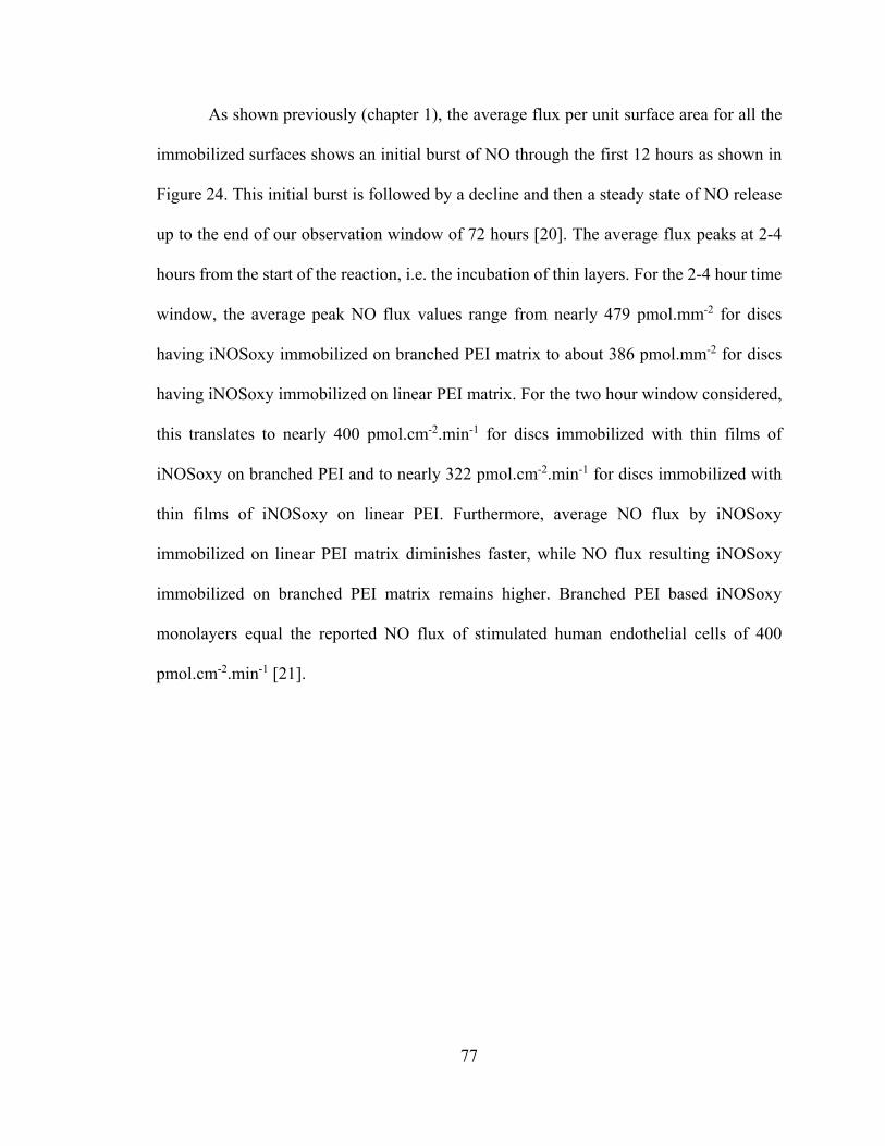
77
As shown previously (chapter 1), the average flux per unit surface area for all the
immobilized surfaces shows an initial burst of NO through the first 12 hours as shown in
Figure 24. This initial burst is followed by a decline and then a steady state of NO release
up to the end of our observation window of 72 hours [20]. The average flux peaks at 2-4
hours from the start of the reaction, i.e. the incubation of thin layers. For the 2-4 hour time
window, the average peak NO flux values range from nearly 479 pmol.mm-2 for discs
having iNOSoxy immobilized on branched PEI matrix to about 386 pmol.mm-2 for discs
having iNOSoxy immobilized on linear PEI matrix. For the two hour window considered,
this translates to nearly 400 pmol.cm-2.min-1 for discs immobilized with thin films of
iNOSoxy on branched PEI and to nearly 322 pmol.cm-2.min-1 for discs immobilized with
thin films of iNOSoxy on linear PEI. Furthermore, average NO flux by iNOSoxy
immobilized on linear PEI matrix diminishes faster, while NO flux resulting iNOSoxy
immobilized on branched PEI matrix remains higher. Branched PEI based iNOSoxy
monolayers equal the reported NO flux of stimulated human endothelial cells of 400
pmol.cm-2.min-1 [21].

78
Figure 24: Average surface flux of NO from iNOSoxy/PEI films immobilized on
branched PEI and linear PEI. Error bars represent standard deviations for 5 trials.
0-2 2-4 4-8 8-12 12-24 24-48 48-720
50
100
150
200
250
300
350
400
450
500 Blank: PEI immobilized PG discs iNOSoxy immobilized on linear PEI iNOSoxy immobilized on branched PEI
NO
flu
x (p
mo
l/m
m2 )
Time period (hours)

79
2.3.3 Electrochemistry and Michaelis-Menten kinetics
2.3.3.1 Electrocatalytic reduction of NO mediated by iNOSoxy in films
Electrochemical analyses of iNOSoxy immobilized electrodes have been used to
provide both the amount of enzyme units on surface and their catalytic turnover rates. First,
in the absence of NO – the reducible substrate – we used the redox active Fe3+-heme of
iNOSoxy to quantify the iNOSoxy adsorption in the two sets of films; one on linear PEI
matrix and the other on branched PEI matrix. Integration of the voltammetric current
provides the faradaic charge passed through the redox active iNOSoxy in each film, which
is an indication of the amount of iNOSoxy present. Like chapter 1, we also used iNOSoxy-
mediated NO catalytic reduction to compare and contrast the amount and catalytic integrity
of adsorbed iNOSoxy units.
Figure 25 shows a typical cyclic voltammogram for a heme containing film for the
specific window. Shown here are the Fe3+/Fe2+ and Fe2+/Fe+ redox couples, of iNOSoxy in
this experiment.
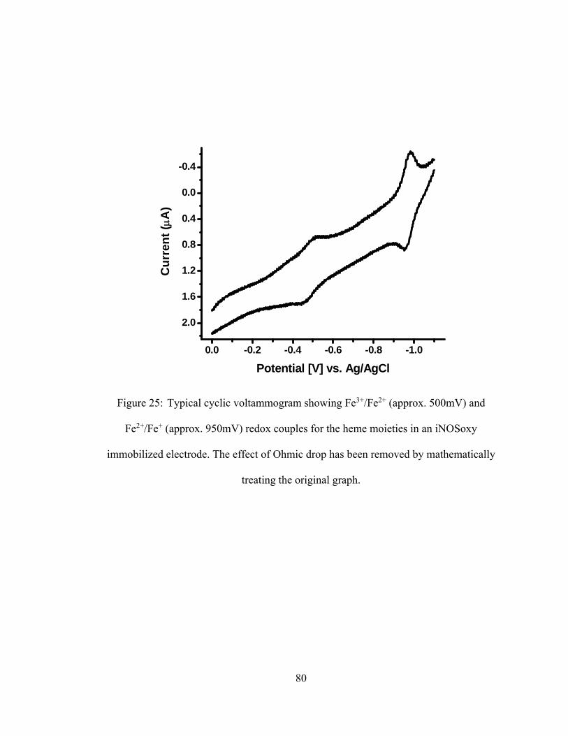
80
Figure 25: Typical cyclic voltammogram showing Fe3+/Fe2+ (approx. 500mV) and
Fe2+/Fe+ (approx. 950mV) redox couples for the heme moieties in an iNOSoxy
immobilized electrode. The effect of Ohmic drop has been removed by mathematically
treating the original graph.
0.0 -0.2 -0.4 -0.6 -0.8 -1.0
2.0
1.6
1.2
0.8
0.4
0.0
-0.4C
urr
ent
(A
)
Potential [V] vs. Ag/AgCl
81
2.3.3.2 iNOSoxy-heme Fe3+ reduction as a quantifier of immobilization
Typical linear sweep voltammograms for Fe3+-heme reduction obtained at 8mV/s
scan rate for a set of the two types of films are shown in Figure 26. We observe a
comparable Faradaic charge transfer by electrodes modified with linear & branched PEI.
In average, we find that iNOSoxy films constructed using linear PEI transfer nearly the
same amount of electrons as films constructed using branched PEI as matrix (approx. 55
nC for branched PEI based films vs. approx. 62 nC for linear PEI based films) as shown in
Figure 27. Here, the same electrode has been modified with alternating PEI/iNOSoxy
monolayers where one set of data were obtained using a linear PEI/iNOSoxy film and the
other using a branched PEI/iNOSoxy film.
Previously, AFM-based cluster analysis showed larger clusters after incubation in
iNOSoxy on branched PEI matrix. If this translates directly into active catalyst
concentration on an electrode surface, the observation must be a higher charge transfer on
branched PEI. The reason for the comparable integrals with approximately the same charge
transfer, despite higher loading in branched PEI, is not clear at this point. However, it is
possible that orientation of adsorbed protein units versus the electrode surface for linear
and branched PEI plays a role in electron transfer, which affects the sampling of iNOSoxy
units during the voltammetric scans in the two cases. However, this potential change of
orientation in the two cases would not affect iNOS activity in terms of NO synthesis, which
explains the results observed in terms of fluxes of NO measured in the previous section

82
Figure 26: Integrals of characteristic Fe3+ reduction in 8mV.s-1 linear sweep
voltammograms for iNOSoxy/PEI films adsorbed on linear PEI and branched PEI. Thin
films immobilized from iNOSoxy solution at pH 8.6.
-0.2 -0.3 -0.4 -0.5 -0.6 -0.7 -0.8 -0.90
50
100
150
200
250
300
350
Ab
solu
te c
urr
ent
valu
e (n
C)
Potential [V] vs. Ag/AgCl
iNOSoxy/branched PEI film iNOSoxy/linear PEI film

83
Figure 27: Average of integrals of the characteristic Fe3+ reduction in 8mV.s-1 linear
sweep voltammograms for iNOSoxy/PEI films adsorbed on linear PEI and branched PEI.
Standard deviation based on data for the same batch of electrodes immobilized at pH 8.6
(N=5).
2.3.3.3 Catalytic reduction of NO by iNOSoxy immobilized on branched and linear
PEI
0 5 10 15 20 25 30 35 40 45 50 55 60 65 70 75 80
0
5
10
15
20
25
30
35
40
45
50
55
60
65
70 iNOSoxy film adsobed on
branched PEI iNOSoxy film adsobed on
linear PEI
Time (Sec)
To
tal c
ha
rge
tra
ns
fer
(nC
)

84
Addition of NO to the solution results in a catalytic peak around -0.9V vs. Ag/AgCl.
In line with previous studies [22, 23], the catalytic current observed, is proportional to NO
concentration. Figure 28 shows the peaks of nitric oxide catalytic reduction mediated by
iNOSoxy films adsorbed onto linear and branched PEI.
Figure 28 is a comparison of peak catalytic currents (IPC) for NO reduction by
iNOSoxy immobilized electrodes. Peak catalytic currents (IPC) for NO reduction by
iNOSoxy immobilized electrodes are comparable between linear PEI and branched PEI
based thin films for each NO concentration. For example, in Figure 28, average IPC values
for NO reduction by thin films of iNOSoxy adsorbed onto linear PEI and branched PEI are
9.8 μA and 10.1 μA respectively, for 120 μM NO concentration. We showed previously
(section 2.3.3.2; Figures 26 & 27) that integral of voltammogram obtained in the absence
of substrate can be comparison of surface-bound active catalyst concentration with regards
to iNOSoxy/PEI on PG electrodes. When substrate NO is present, current, i.e., the rate of
charge transfer by the enzyme in catalytic reduction, becomes a direct measurement of
enzyme kinetics.

85
Figure 28: Cyclic voltammogram (200 mV.s-1) for catalytic NO reduction iNOSoxy
immobilized on linear PEI and branched PEI, measured at the same NO concentration
(120 μM). Immobilization pH is 8.6.
0.2 0.0 -0.2 -0.4 -0.6 -0.8 -1.0 -1.2 -1.4
-2
0
2
4
6
8
10
Cu
rre
nt
(A
)
Potential [V] vs. Ag/AgCl
linear PEI/iNOSoxy branched PEI/iNOSoxy blank

86
2.3.3.4 Michaelis-Menten kinetics
According to the Michaelis-Menten model, the rate of an enzyme catalyzed reaction
denoted by V, is given as follows.
V ⨉
(2.1)
Vmax is the maximum rate of substrate turnover, kM is the substrate concentration at
half maximum of the rate of conversion, and, kcat is the turnover number. In the
electrochemical form, the rate of catalysis is Icat measured in the voltammetric scan.
According to Michaelis-Menten model, Icat is given as follows.
I ⨉
(2.2)
Γ is the surface active catalyst concentration, A is the active surface area electrode,
and, F is the Faraday constant. While [S] is the substrate concentration, kcat denotes the
turnover number. Therefore, typical enzyme saturation kinetics can be observed in a plot
of the normalized catalytic current against substrate (NO) concentration. Figure 29 shows
the Michaelis-Menten plot for the electrodes modified using linear and branched PEI as
matrices and iNOSoxy as the active layer. Michaelis-Menten non-linear curve fitting
derives kM and kcat for the two sets of data, representing the conditions of immobilization
and activity.

87
Figure 29: Average catalytic peak current for NO reduction at the surfaces of thin films
of iNOSoxy adsorbed at pH 8.6 onto linear PEI and branched PEI. Standard deviation
based on data for the same batch of electrodes immobilized using linear and branched
PEI (N=5).
0 20 40 60 80 100 120 140 160 180 200
0
20
40
60
80
100
120
140
160 Michaelis-Menten fitting
PG electrode with iNOSoxy film immobilized at pH 7.0 Michaelis-Menton curve for pH 7.0 immobilized film PG electrode with iNOSoxy film immobilized at pH 8.6 Michaelis-Menton curve for pH 8.6 immobilized film
Substrate [NO] concentration (M)
I ca
t / n
FAs
-1)
0
5
10
15
20
25
30
35
% (
?Y)

88
iNOSoxy films grown on branched PEI and linear PEI show comparable turnover
rates. A slight decrease in the rate of catalysis is observable for the branched PEI based
thin films, possibly due to the hindered electron shunt resulting from stacked iNOSoxy
units. Non-linear fitting of observed traces using the Michaelis-Menten kinetic model
yields the kM and kcat values for the two films shown in table 2.
Type of PEI used for iNOSoxy Immobilization
kM (μM) kcat (s‐1)
Linear PEI 69.6±4.8 184.4±5.3
Branched PEI 63.7±5.1 184.0±5.9
Table 2: Extracted Michaelis-Menten parameters from non-linear regression fitting
using Michaelis-Menten model
Michaelis-Menten saturation kinetics do not show a significant difference in the
rate of catalysis observed, for the iNOSoxy films immobilized on linear PEI or branched
PEI. Our previous work showed a significant change in the rate of catalysis and different
kM and kcat values, when the iNOSoxy/PEI films were immobilized at different pH. This
was attributed to the possible structural distortions of the protein that lead to changes in
dynamic motions of the enzyme [24-27]. In the current work, iNOSoxy is adsorbed at pH
8.6 for both linear and branched PEI based thin films. Therefore, the enzyme structure
remains potentially unaffected when the enzyme is immobilized on either the linear PEI or
the branched PEI, which explains the comparable kinetic parameters KM and kcat of the two
sets of iNOSoxy films adsorbed onto linear PEI and branched PEI.
89
2.4 Conclusion
This chapter explored the effect of PEI structure (linear vs. branched) on iNOSoxy
loading in LbL films. We used branched PEI to modulate the iNOSoxy loading on PEI
layers. We report higher activity by the thin films formed on branched PEI compared to
thin films built on linear PEI. The activity of thin films described in this chapter is
comparable to the activity of alternating (3)NOS-(3)PEI multilayer thin film based LbL
method.
The specific focus of this chapter has been to explore the use of polymer branching
and the corresponding increase of polymer charge density to optimize enzyme loading on
PEI. Active iNOSoxy concentration in thin films explored by electrochemical data implies
comparable enzyme loading onto the outermost layer in linear and branched PEI based thin
films. However, the AFM imaging of films made with branched PEI suggests higher
density of packed enzyme clusters compared to smaller clusters in the case of films made
with linear PEI. Assay based activity results confirm the higher loading onto branched PEI
based films compared to linear PEI based films.
90
2.5 Reference
1. Walford, G., Locallzo, J., Nitric oxide in vascular biology. Journal of Thrombosis
and Haemostasis, 2003. 1(10): p. 2112-2118.
2. Ignarro, L.J., Biological actions and properties of endothelium-derived nitric oxide
formed and released from artery and vein. Circulation Research, 1989. 65(1): p. 1-
21.
3. Bjellqvist, B., Basse, B., Olsen, E. and Celis, J.E., Reference points for comparisons
of two-dimensional maps of proteins from different human cell types defined in a
pH scale where isoelectric points correlate with polypeptide compositions.
Electrophoresis, 1994. 15(3-4): p. 529-539.
4. Gasteiger E., H.C., Gattiker A., Duvaud S., Wilkins M.R., Appel R.D., Bairoch A.,
Protein Identification and Analysis Tools on the ExPASy Server, ed. J.M. Walker.
The Proteomics Protocols Handbook, Humana Press (2005).
5. Bjellqvist, B., Hughes, G.J., Pasquali, Ch., Paquet, N., Ravier, F., Sanchez, J.-Ch.,
Frutiger, S., Hochstrasser, D.F., The focusing positions of polypeptides in
immobilized pH gradients can be predicted from their amino acid sequences.
Electrophoresis, 1993. 14(10): p. 1023-1031.
6. Meier, U. and C.W. Schläpfer, Interaction between Cl− and linear and branched
polyethyleneimine in aqueous solution studied by 35Cl- and 37Cl-NMR. Berichte
der Bunsengesellschaft für physikalische Chemie, 1998. 102(8): p. 1011-1018.

91
7. Wu, C.-b., J.-y. Hao, X.-m. Deng, and Y. Liu, Random branched
poly(hydroxyetheramine): a novel polycation with proton sponge effect and high
density of discrete charge. Polymer Bulletin, 2008. 60(5): p. 635-645.
8. Boussif, O., F. Lezoualc'h, M.A. Zanta, M.D. Mergny, D. Scherman, B. Demeneix,
and J.P. Behr, A versatile vector for gene and oligonucleotide transfer into cells in
culture and in vivo: polyethylenimine. Proceedings of the National Academy of
Sciences, 1995. 92(16): p. 7297-7301.
9. Mateos-Timoneda, M.A., M.C. Lok, W.E. Hennink, J. Feijen, and J.F. Engbersen,
Poly(amido amine)s as gene delivery vectors: effects of quaternary nicotinamide
moieties in the side chains. ChemMedChem, 2008. 3(3): p. 478-86.
10. Voigt, U., V. Khrenov, K. Tauer, M. Hahn, W. Jaeger, and R.v. Klitzing, The effect
of polymer charge density and charge distribution on the formation of multilayers.
Journal of Physics: Condensed Matter, 2003. 15(1): p. S213.
11. Drovetskaya, T.V., E.F. Diantonio, R.L. Kreeger, J.L. Amos, and D.P. Frank, New
high-charge density hydrophobically modified cationic HEC polymers for
improved co-deposition of benefit agents and serious conditioning for problem
hair. J Cosmet Sci, 2007. 58(4): p. 421-34.
12. Shin, Y., J.E. Roberts, and M.M. Santore, The relationship between
polymer/substrate charge density and charge overcompensation by adsorbed
polyelectrolyte layers. J Colloid Interface Sci, 2002. 247(1): p. 220-30.
13. Stuehr, D.J., Purification and properties of nitric oxide synthase. Methods in
Enzymology, 1996. 268: p. 324-333.
92
14. Tiso, M., Strub, A., Hesslinger, C., Kenney, C.T., Boer, R., Stuehr, D.J.,
BYK191023 (2-[2-(4-Methoxy-pyridin-2-yl)-ethyl]-3H-imidazo[4,5-b]pyridine) is
an NADPH- and time-dependant irreversible inhibitor of inducible nitric oxide
synthase. Molecular Pharmacology, 2008. 73(4): p. 1244-1253.
15. Wang, Z., Wei, C., Stuehr, D.J., A Conserved Tryptophan 457 Modulates the
Kinetics and Extent of N-Hydroxy-l-Arginine Oxidation by Inducible Nitric-oxide
Synthase. The Journal of Biological Chemistry, 2002. 277(15): p. 12830-12837.
16. Rusling, J.F., Nassar, A.F., Enhanced electron transfer for myoglobin in surfactant
films on electrodes. Journal of the American Chemical Society, 1996. 115(25): p.
11891-11897.
17. Waitumbi, J. and A. Warburg, Phlebotomus papatasi saliva inhibits protein
phosphatase activity and nitric oxide production by murine macrophages. Infect
Immun, 1998. 66(4): p. 1534-7.
18. Jun, H.-W., TaiteL.J., West, J.L., Nitric oxide-producing polyurethanes.
Biomacromolecules, 2005. 6(2): p. 838-844.
19. Matl, F.D., A. Obermeier, S. Repmann, W. Friess, A. Stemberger, and K.D. Kuehn,
New anti-infective coatings of medical implants. Antimicrob Agents Chemother,
2008. 52(6): p. 1957-63.
20. Miller, P.E., Carlton, D., Deierhoi, M.H., Redden, D.T., Allon, M. , Natural history
of arteriovenous grafts in hemodialysis patients. American Journal of Kidney
Diseases, 2000. 36(1): p. 68-74.

93
21. Vaughn, M.W., L. Kuo, and J.C. Liao, Estimation of nitric oxide production and
reaction rates in tissue by use of a mathematical model. Am J Physiol, 1998. 274(6
Pt 2): p. H2163-76.
22. Bayachou, M., Abou-Diwan, C. , US Patent # 2009/073643. 2009.
23. Immoos, C.E., Chou, J., Bayachou, M., Blair, E., Greaves, J., Farmer, P.J.,
Electrocatalytic reductions of nitrite, nitric oxide, and nitrous oxide by
thermophilic cytochrome P450 CYP119 in film-modified electrodes and an
analytical comparison of its catalytic activities with myoglobin. Journal of the
American Chemical Society, 2004. 126(15): p. 4934-4942.
24. Agarwal, P.K., Geist, A., Gorin, A., Protein dynamics and enzymatic catalysis:
investigating the peptidyl-prolyl cis-trans isomerization activity of cyclophilin A.
Biochemistry, 2004. 43(33): p. 10605-10618.
25. Agarwal, P.K., Billeter, S.R., Rajagopalan, P.T,, Benkovic, S.J., Hammes-Schiffer,
S., Network of coupled promoting motions in enzyme catalysis. Proc. Natl. Acad.
Sci., 2002. 99(5): p. 2794-2799.
26. Yang, L.W., Bahar, I., Coupling between catalytic site and collective dynamics: A
requirement for mechanochemical activity of enzymes. Structure, 2005. 13(6): p.
893-904.
27. Tousignant, A., Pelletier, J.N. , Protein motions promote catalysis. Chemistry &
Biology, 2004. 11(8): p. 1037-1042.

94
CHAPTER III: INDUCIBLE NITRIC OXIDE SYNTHASE OXYGENASE
(iNOSoxy) ENCAPSULATED IN ELECTROSPUN FIBER SCAFFOLDS AND
MATS
3.1 Introduction
3.1.1 Electrospinning
Electrospinning is an economical method for fabricating scaffolds and mats that
can host and release therapeutic agents while functioning as support structures for tissue
and cell growth. Electrospinning produces polymer fibers with diameters in the nano to
micrometer range. Electrospinning is used efficiently in a variety of tissue-engineering
applications for different types of scaffolds [1-4], controlled drug-delivery platforms [5],
and sensors [6, 7]. For example, materials such as DNA has been successfully embedded
into and released from electrospun scaffolds, where the DNA has been used for transfection
[8]. In our current work, electrospun scaffolds and mats encapsulate an enzyme, nitric
oxide synthase, involved in the generation and release of nitric oxide (NO) upon contact

95
with the buffer containing NOS reaction cocktail. Release of NO is useful for the scaffold
to counteract thrombogenesis, which could be an advantage for scaffolds whose primary
function is acting as a solid support for cells in regenerative medical applications.
A homogenized electrospinning mixture of polymer, solvent and active ingredient
(the enzyme in our case) is contained in a syringe. This is horizontally driven at a flow rate
of several milliliters per hour to elute from the needle tip. The eluting mixture, rather than
falling along gravity, is attracted to a mandrel, due to a potential difference applied between
the needle and the mandrel. The ejecting stream of electrospinning mixture forms a Taylor
cone at the edge of the needle, before thinning-out along its direction [9, 10]. Typical
voltage biases range from 5-30 kV and the air-gap distance between the needle and
collecting mandrel range from 15-30 cm. On elution, the polymer mixture with its
constituents is driven as a continuous stream of wet fiber. The electrospinning chamber
facilitates the evaporation of solvent component from the spinning polymer solution. As
the solvent evaporates, the jet solidifies, forming a polymer fiber. The spinning mandrel
collects the fiber and forms either a mat or a scaffold depending on the shape and size of
the mandrel.
The encapsulation of active agents in electrospun fibers can be achieved in two
major electrospinning methods: (1) coaxial electrospinning and, (2) emulsion
electrospinning. Coaxial electrospinning uses two separate spinning streams of fluids for
the electrospinning process. A polymer shell and a core consisting of encapsulating
ingredient are pumped through separate feeder lines, toward the tip of the coaxial double –
bore needle. Coaxial electrospinning has been used to contain bovine serum albumin (BSA)
in polycaprolactone [11, 12]. A number of pharmaceutical agents such as tetracycline
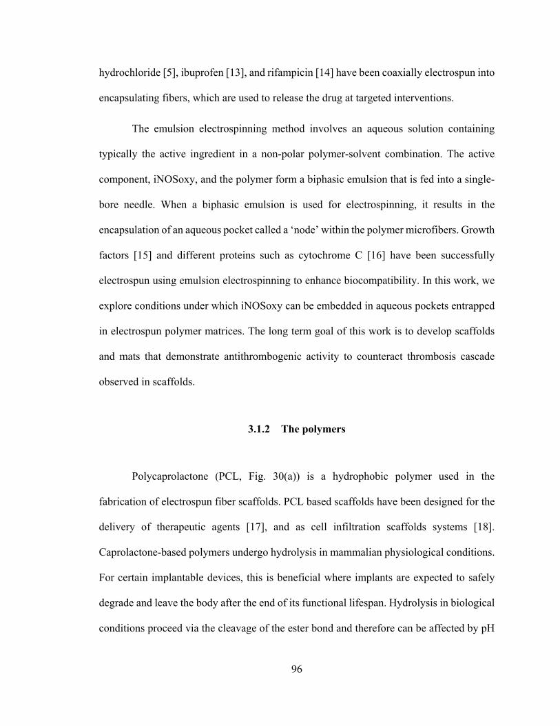
96
hydrochloride [5], ibuprofen [13], and rifampicin [14] have been coaxially electrospun into
encapsulating fibers, which are used to release the drug at targeted interventions.
The emulsion electrospinning method involves an aqueous solution containing
typically the active ingredient in a non-polar polymer-solvent combination. The active
component, iNOSoxy, and the polymer form a biphasic emulsion that is fed into a single-
bore needle. When a biphasic emulsion is used for electrospinning, it results in the
encapsulation of an aqueous pocket called a ‘node’ within the polymer microfibers. Growth
factors [15] and different proteins such as cytochrome C [16] have been successfully
electrospun using emulsion electrospinning to enhance biocompatibility. In this work, we
explore conditions under which iNOSoxy can be embedded in aqueous pockets entrapped
in electrospun polymer matrices. The long term goal of this work is to develop scaffolds
and mats that demonstrate antithrombogenic activity to counteract thrombosis cascade
observed in scaffolds.
3.1.2 The polymers
Polycaprolactone (PCL, Fig. 30(a)) is a hydrophobic polymer used in the
fabrication of electrospun fiber scaffolds. PCL based scaffolds have been designed for the
delivery of therapeutic agents [17], and as cell infiltration scaffolds systems [18].
Caprolactone-based polymers undergo hydrolysis in mammalian physiological conditions.
For certain implantable devices, this is beneficial where implants are expected to safely
degrade and leave the body after the end of its functional lifespan. Hydrolysis in biological
conditions proceed via the cleavage of the ester bond and therefore can be affected by pH

97
and temperature [6]. Studies of mouse fibroblast adhesion onto electrospun scaffolds have
also shown the biocompatibility of PCL [19].
Polyvinyl alcohol (PVA, Figure 30(b)) is a water-soluble polymer used in
electrospinning mats and scaffolds. PVA in electrospun implantable systems showed
resistance against implant infection [20]. Electrospun PVA fiber mats are important as
dissolving drug delivery systems that leave no harmful residue [21]. However, when longer
functionality is desired, cross-linking can increase the stability of PVA fibers, which makes
them resist degradation in aqueous systems, including body fluids [22, 23]. However,
release and activity of embedded ingredients could be affected by the cross-linking process
[24].
Polyethylene-co-vinyl acetate (PEVA, Figure 30(c)) is another hydrophobic
polymer used in fabricating electrospun scaffolds for drug delivery [17]. PEVA is inert
and non-biodegradable under human physiological conditions. In-vivo experiments have
shown PEVA implants to be biocompatible, with evidence of tissue encapsulation of
implants [25].

98
Figure 30: Structures of a) polycaprolactone, b) polyvinyl alcohol and, c) polyethyl-vinyl
acetate.
(a) (b)
(c)

99
3.2 Experimental
3.2.1 iNOSoxy structural study by FTIR in different organic solvent mixtures used
in electrospinning
We used FTIR analysis to characterize iNOSoxy emulsified in different solvents
used in the polymer/solvent mixture. We used the diamond ATR crystal assembly (PIKE
technologies) coupled to a FTIR (Varian Digilab Scimitar series FTS 2000). Aliquots of
10 μl of ~100 μM iNOSoxy in EPPS buffer were combined with volumes of 60, 70, 80 and
90 μl of either chloroform or acetone, and homogenized. The blank measurement was
obtained by placing a 100 μl drop of the respective solvent on the ATR crystal. Aliquots
of 100 μl of homogenized iNOSoxy-solvent mixtures were placed on the crystal to acquire
FTIR spectra.
3.2.2 Activity of iNOSoxy in polymer mixture before electrospinning
When bathed in buffer containing iNOSoxy substrate cocktail, the enzyme
catalyzes the production and release of NO [26, 27]. Similar to the assay methods used in
sections 1.2.6 and 2.2.3, we used the Griess reagent system to monitor NO release in
electrospinning mixture in order to characterize iNOSoxy activity. The combined
iNOS/polymer mixture (25 μl of enzyme in 475 μl in polymer mix) was vortexed at several
3-second cycles. An aliquot of 800 μl of EPPS buffer was added to the vortexed polymer-
enzyme mixture. The combination was again vortexed in the same manner, to partially
extract iNOSoxy from the emulsified spinning mixture into the buffer phase, which was

100
used for testing enzyme activity. A volume of 300 μl of EPPS layer was transferred into a
500 μl cuvette. Aliquots of 300 µl each of Griess reagent (sulfanilamide and NED,
Promega) were added to the cuvette. After 10 minutes, UV-Vis spectra were recorded. In
addition, the EPPS layer used to re-extract the enzyme was removed from the vial
containing the iNOSoxy/polymer emulsion. The remaining iNOSoxy/polymer mixtures
were separated by centrifugation in 1 ml Microcon® filters at 10,000 rpm for 1 minute. The
separated enzyme portions remaining in residue were washed and incubated with 500 μl of
NOS reaction cocktail for 15 minutes. NO output was measured using the Griess assay to
determine the activity of trapped enzyme. A total NO output, produced by both the
extracted and trapped iNOSoxy was measured, and compared against an output of NO by
a native enzyme aliquot used in the characterization.
3.2.3 Electrospinning apparatus
A sketch of the electrospinning apparatus is shown in Figure 31. The apparatus
consists of a syringe, typically 5 cm3, containing the spinning mixture. The syringe is
mounted on, and driven by a syringe pump (model 100 KD scientific Inc., New Hope, PA).
The needle (gauge range of 16-20) is cut flat, to facilitate the Taylor cone formation [9,
10]. A high voltage DC power supply (Spellman, CWE1000R, Spellman High Voltage
Electronics Corp., Hauppauge, NY) applies the bias between needle and the collecting
mandrel. The mandrels are made of steel or coated alloys and are grounded. The oscillation
and the rotation of the mandrel are driven by computer numeric control motors. The
oscillation is made to glide on a linear drive perpendicular to the direction of ejection. The

101
electrospinning assembly is contained in a cage made of commercial plexiglass with
evacuation lines fitted for removing volatile solvent. Ambient conditions such as humidity
and temperature are carefully monitored.
Figure 31: A schematic representation of a typical electrospinning apparatus.
3.2.4 Preparation of polymer solution and electrospinning parameters
A mass of 2.2 g of polycaprolactone (70,000–90,000 MW, Sigma Aldrich by GPC)
was dissolved in 15 ml of chloroform (Sigma) overnight to achieve a homogenous solution
of ~10% w/w PCL. For polyethylene-co-vinyl acetate, (Sigma Aldrich), a mass of 6.0 g
was dissolved in 29 ml of chloroform (Sigma) overnight to achieve a homogenous solution
15cm
Fiber Mandrel
Syringe
Suspension
Drive
15kV
102
of ~14% w/w PEVA. A mass of 2 g of polyvinyl alcohol (99%, hydrolyzed, Sigma Aldrich)
was dissolved in 20 ml of DI water to make ~10% w/w solution of PVA.
We selected a ratio of 20:1 v/v for polymer-solvent to iNOSoxy throughout the
experiments, after examining trials for both lower and higher ratios. A volume of 950 μl of
polymer solution was pipetted into a capped conical vial. To this, an aliquot of 50 μl of 100
μM iNOSoxy in EPPS buffer was added. The suspension was vortexed in several 2-5
second cycles. The resultant 1 ml homogenized mixture was loaded into the 5 cm3 syringe
for electrospinning.

103
Polymer / solvent 10% w/w PCL in
chloroform
14% w/w PEVA in
chloroform
10% w/w PVA in
water
Polymer/solvent :
iNOSoxy ratio (v/v) 20:1 20:1 20:1
Air-gap distance (cm) 15 30 15
Voltage (kV) 15 15 15
Flow rate (ml/hour) 1.0 3.0 1.0
Table 3: Electrospinning parameters for each polymer/solvent system.
3.2.5 Optical microscopic imaging of electrospun scaffolds and mats
Electrospun microfibers were collected in a glass microscope slides (Fisher
Scientific). A number of samples at different distances from the needle were collected and
imaged. The purpose was to monitor solvent evaporation along the ejection path and
formation of nodes. We used a Nikon Eclipse TS100 inverted optical microscope using
10X, 20X and 40X magnifications. Images were captured using a digital camera connected
to the ocular. Image analysis and rendering was done using Qscope software.
We used Sudan IV (Sigma) as a staining reagent to observe separation of polar and
non-polar phases in the electrospinning process. We used a ratio of 1 mg of Sudan IV per

104
1 ml of homogenized electrospinning mixture. Optical microscopic images were obtained
separately for stained electrospun scaffolds. We also used fluorescein
isothiocyanate (FITC) to observe the nodes formed in emulsion electrospinning method
where aqueous solvent pockets are encapsulated.
3.2.6 Scanning Electron Microscopic imaging of electrospun scaffolds and mats
We used JEOL JSM-6510LV series Scanning Electron Microscope (SEM) and
Inspect F-50 field emission SEM (FE-SEM) for imaging electrospun scaffolds and mats.
We used aluminum stubs and square specimen mounts to fix scaffolds and mats for gold
sputtering and imaging. We used Quorum EMS (Quorum Technologies) sputter coater for
gold sputtering. All cylindrical scaffolds were cut open and mounted on stubs. Image-J64
software was used to analyze the fiber diameters.
3.2.7 Activity of iNOSoxy enzyme embedded in PVA scaffold through Griess
reagent system
Several 2 cm × 2 cm non-crosslinked PVA scaffold sections were cut from each
batch of the spun fiber scaffolds containing iNOSoxy. The control sample was a section of
scaffold that did not have iNOSoxy in its aqueous suspension during the electrospinning
process. The scaffold sections were placed in labeled scintillation vials. Volumes of 5 ml
of the NOS reaction cocktail containing 250 µM N-hydroxy-L-arginine (NHA), 10 µM

105
tetrahydrobiopterin (H4B), and 400 µM dithiothreitol (DTT) prepared in 100 mM
phosphate buffer adjusted to pH 7.4, were added to each of the vials. The enzyme-catalyzed
reaction was triggered at 37˚C by adding hydrogen peroxide to a final concentration of 150
mM. Aliquots of 100 µl of reaction medium were retrieved and combined with 100 µl of
each of Griess reagents R1 (sulfanilamide) and R2 (N-(1-naphthyl)ethylenediamaine)
(Cayman Chemical Company) in a UV-Vis cuvettes. Absorbance values at 540 nm against
the reagent blank were recorded (UV-Vis; Model 8543, Agilent Technologies) after a 10-
minute incubation time for all assay aliquots. Concentrations were determined using a
standard calibration curve prepared under the same conditions.
3.2.8 Activity of iNOSoxy enzyme embedded in scaffold using a fluorometric
method
Our preliminary activity characterizations on electrospun fiber based iNOSoxy
prompted the use of a more sensitive assay than the Griess assay system. We used the DAF-
FM (4-amino-5-methylamino-2',7'-difluorofluorescein) diacetate assay [28, 29]. Figure 32
is a schematic representation of the general reaction of DAF-FM based fluorescence assay
used to determine NO concentration.
Scaffold sections of 2 cm × 2 cm were cut from each batch of the iNOSoxy enzyme
containing PCL and PEVA spun fiber scaffolds. For the control experiment, we used a
section of scaffold electrospun without iNOSoxy. The scaffold sections were placed in
labeled scintillation vials. Volumes of 1 ml of the reaction cocktail containing 250 µM N-
hydroxy-L-arginine (NHA), 10 µM tetrahydrobiopterin (H4B), and 400 µM dithiothreitol
(DTT) dissolved in 100 mM phosphate buffer medium and adjusted to a final pH value of

106
7.4 were added to each of vial. The enzyme catalyzed reaction was activated by adding
hydrogen peroxide to a final concentration of 150 mM. Scaffolds were incubated at 37˚C.
Aliquots of 150 µl of reaction media were taken at 2, 4, 8, 12, 24, 48 & 72 hour lapse times
for analysis. The reaction aliquots were placed in opaque microplate wells. Aliquots of 150
µl of 10 µM DAF-FM diacetate (4-amino-5-methylamino- 2′,7′-difluorofluorescein
diacetate, Molecular Probes Inc.) were added to each well. We used Hitachi f-7000
fluorescence spectrophotometer. Excitation wavelength was set at 495 nm, while emission
was monitored at 515 nm. A standard calibration curve for the NO concentration range
from 0.1 µM to 12.0 µM was used to measure NO released in reactions catalyzed by
iNOSoxy in electrospun scaffolds and mats.

107
Figure 32: Reaction scheme for the detection of NO by DAF-FM diacetate.
O-O
CH3
NH
NH2
F
O
O
O-
F
OO
CH3
O
CH3
NH
NH2
F
CH3
O
O
O
O F
NO
N
O-O
CH3
N
N
F
O
O
O-
F
DAF-FM Diacetate
DAF-FMBenzotriazole derivative
(fluorescent)
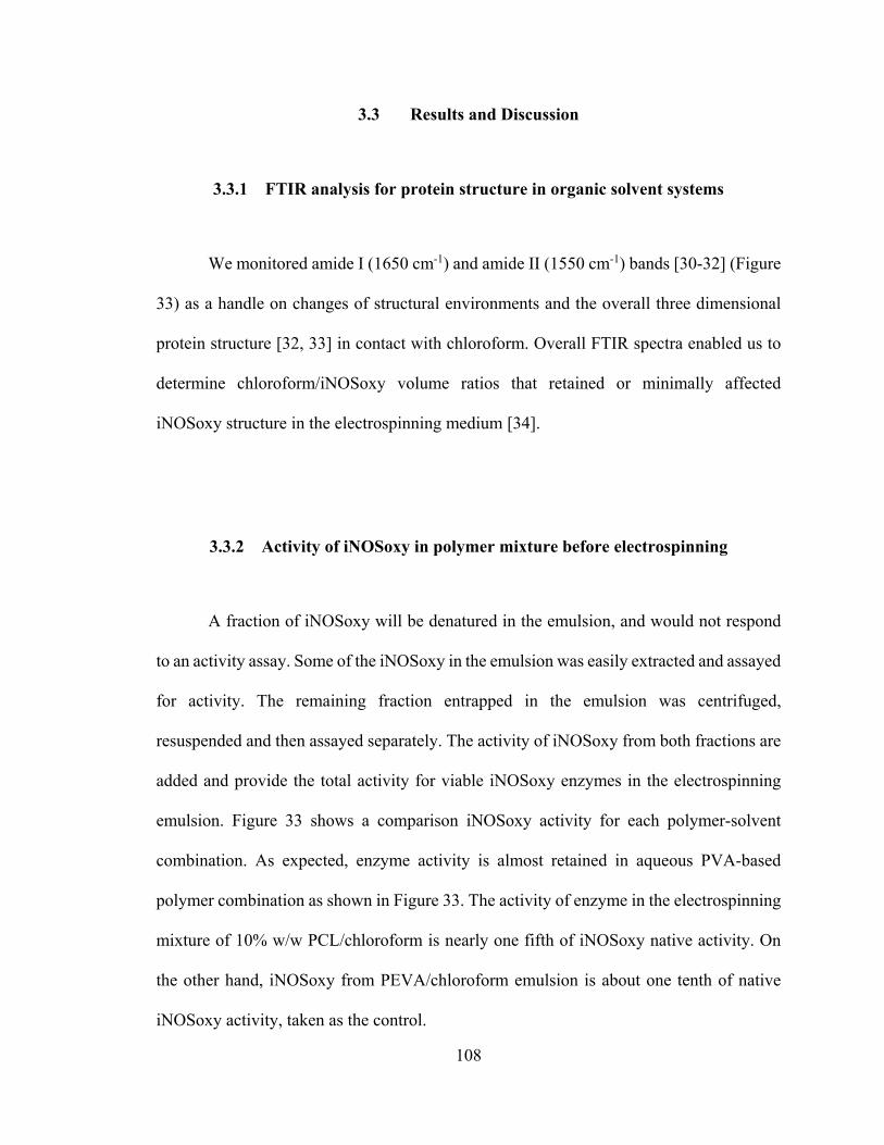
108
3.3 Results and Discussion
3.3.1 FTIR analysis for protein structure in organic solvent systems
We monitored amide I (1650 cm-1) and amide II (1550 cm-1) bands [30-32] (Figure
33) as a handle on changes of structural environments and the overall three dimensional
protein structure [32, 33] in contact with chloroform. Overall FTIR spectra enabled us to
determine chloroform/iNOSoxy volume ratios that retained or minimally affected
iNOSoxy structure in the electrospinning medium [34].
3.3.2 Activity of iNOSoxy in polymer mixture before electrospinning
A fraction of iNOSoxy will be denatured in the emulsion, and would not respond
to an activity assay. Some of the iNOSoxy in the emulsion was easily extracted and assayed
for activity. The remaining fraction entrapped in the emulsion was centrifuged,
resuspended and then assayed separately. The activity of iNOSoxy from both fractions are
added and provide the total activity for viable iNOSoxy enzymes in the electrospinning
emulsion. Figure 33 shows a comparison iNOSoxy activity for each polymer-solvent
combination. As expected, enzyme activity is almost retained in aqueous PVA-based
polymer combination as shown in Figure 33. The activity of enzyme in the electrospinning
mixture of 10% w/w PCL/chloroform is nearly one fifth of iNOSoxy native activity. On
the other hand, iNOSoxy from PEVA/chloroform emulsion is about one tenth of native
iNOSoxy activity, taken as the control.

109
Figure 33: Activity of iNOSoxy prior to electrospinning in three different homogenized
polymer/solvent mixtures and iNOSoxy. Control is provided by iNOSoxy enzyme in
EPPS buffer. Error bars represent standard deviations in repeated trials (N=3).
0
200
400
600
800
1000
1200
1400
1600
10% PVA / water
14% PEVA / chloroform
10% PCL / chloroform
100M iNOSoxy in EPPS
Activity of iNOSoxy in EPPS buffer NO production by iNOSoxy strongly embedded in the emulsion NO production by iNOSoxy weakly associated with the emulsion
Cu
mu
lati
ve N
O o
utp
ut
(m
ol)

110
3.3.3 Physical characteristics of electrospun fiber scaffolds and mats
Higher w/w ratios of solvent to polymer affect the continuity of the polymer fiber
while lower ratios coagulate the spinning mix at the needle due to different viscoelasticity.
Using the 1:20 v/v ratio of polymer/solvent to iNOSoxy in buffer, two types of electrospun
scaffolds were fabricated and used for characterization.
The main type of scaffold we fabricated was the vessel-like tubular electrospun
scaffold. We used the 2 mm and 4 mm diameter smaller mandrels to spin PCL scaffolds of
this type. Scaffolds are retrieved by sliding along the mandrel. Figure 34 shows an image
of a typical PCL scaffold. The resulting material is cut into sections and used for activity
characterization and imaging. PCL scaffolds are relatively rigid mechanically and returns
to original form easily after distortion of its cylindrical shape. Figure 35 shows a section
of PEVA scaffold. Unlike PCL, PEVA scaffolds tend to adhere to mandrel and other
surfaces. The original scaffold is cut along a line parallel to spinning axis. The other type
is the electrospun fiber mat. Figure 36 shows a PVA scaffold spun using the larger 50 mm
diameter mandrel. Sections ranging from 5 cm × 5 cm to 2 cm × 2 cm were used for activity
assays, while smaller sections were used for imaging.

111
Figure 34: A photograph of a section of PCL scaffold retrieved from the small 4 mm
mandrel immediately after electrospinning. Electrospinning conditions: Air-gap distance:
15 cm, Potential: 15 kV, Electrospinning emulsion ratio (v/v): 20:1 (Polymer mixture :
iNOSoxy containing buffer), Flow rate 1 ml/hr.
Figure 35: A photograph of a section of PEVA scaffold cut open and retrieved from the
small 4 mm mandrel after electrospinning. Electrospinning conditions: Air-gap distance:
30 cm, Potential: 15 kV, Electrospinning emulsion ratio (v/v): 20:1 (Polymer mixture :
iNOSoxy containing buffer), Flow rate 3 ml/hr.

112
Figure 36: A photograph of a section of PVA scaffold retrieved from the large mandrel
immediately after electrospinning. Electrospinning conditions: Air-gap distance: 15 cm,
Potential: 15 kV, Electrospinning emulsion ratio (v/v): 20:1 (Polymer mixture : iNOSoxy
containing buffer), Flow rate 1 ml/hr.

113
Both PCL and PEVA based scaffolds maintain their physical form in aqueous
solutions, for all activity characterizations carried-out in EPPS buffer. PVA scaffolds
dissolve considerably in aqueous reaction cocktail where activity assays were carried out.
Initially, the original mats coalesce into polymer aggregates that continue to degrade and
dissolve. Crosslinked PVA mats do not dissolve. Both the crosslinked and non-crosslinked
forms of PVA could be useful, depending on the application. Rapidly dissolving, drug
eluting scaffolds and mats have been investigated previously for their specific benefits for
PCL based systems [35, 36]. Other polymer systems have also been studied for
biodegradable nature of the scaffolds and the accompanying benefits [14].
3.3.4 Optical microscopic imaging
The encapsulation of aqueous pockets in the PCL and PEVA polymer microfiber
is driven by the separation of polar aqueous pockets from the non-polar solvent during the
electrospinning process. In contrast, PVA shows no clear separation of ‘nodes’ as expected.
This is due to the fact that both the active component, iNOSoxy enzyme and polymer
matrix are part of the same aqueous phase.
Figure 37 shows an electrospun microfiber scaffold stained with Sudan IV. Polar
aqueous phase containing ‘nodes’ are shown, which are entrapped in the non-polar PCL
polymer microfibers. Sudan IV has been used previously to provide information on the
composition of PCL fiber mats [37]. Figure 38 shows optical microscopic images of PVA
and PCL microfibers respectively, with embedded iNOSoxy.

114
Figure 37: Optical microscopic images of PCL microfibers stained with Sudan IV.
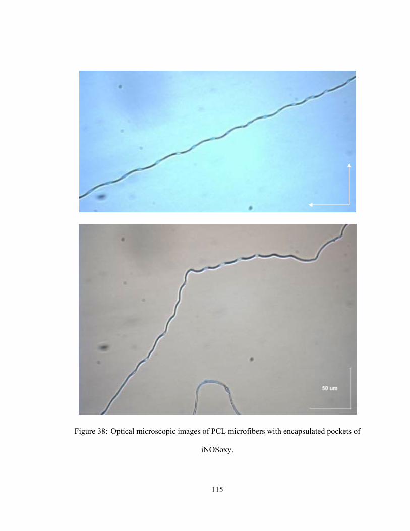
115
Figure 38: Optical microscopic images of PCL microfibers with encapsulated pockets of
iNOSoxy.

116
Figure 39 shows the fluorescence images of PCL microfibers stained with FITC.
With its isothiocyanate group, FITC is known to react and tag proteins [12, 18, 38-40]. The
high fluorescence intensity in ‘nodes’ in Figure 39 corresponds to iNOSoxy proteins
entrapped in the PCL microfiber.
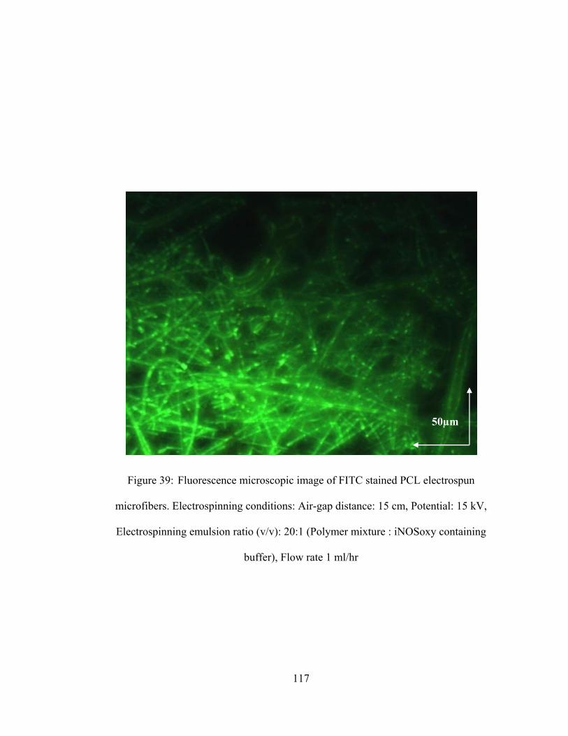
117
Figure 39: Fluorescence microscopic image of FITC stained PCL electrospun
microfibers. Electrospinning conditions: Air-gap distance: 15 cm, Potential: 15 kV,
Electrospinning emulsion ratio (v/v): 20:1 (Polymer mixture : iNOSoxy containing
buffer), Flow rate 1 ml/hr
50µm

118
3.3.5 Scanning electron microscopic imaging
Scanning electron microscopic (SEM) images help visualize fiber morphology,
internal scaffold structures, pore sizes and level of encapsulation [18]. In general, SEM
images of the scaffolds show random orientations of fibers. Figure 40(a) and (b) shows
successful encapsulation of the aqueous pockets in a PCL microfiber. Average diameter of
fibers that successfully encapsulate aqueous pockets is less than few microns.
Figure 41(a) and (b) show SEM images of a section of an electrospun PVA mat.
PVA is water soluble, and hence is electrospun in aqueous buffer with iNOSoxy in the
same phase. Unlike in a two-phase emulsion electrospinning where pockets are observed,
electrospun PVA mats are not expected to show clear separation of entrapped pockets.
Instead, the active component - iNOSoxy - is distributed evenly within the fibers.
Image-J64 software was used to measure fiber diameter of PCL microfibers based
on SEM images [18, 41]. Analysis of SEM images shows that iNOSoxy enzyme and/or
EPPS buffer containing fibers are larger in diameter than the control samples for the
analyzed PCL scaffolds. Control samples are scaffolds electrospun with PCL without
iNOSoxy or buffer. Figure 42 summarizes the fiber diameter increase upon embedding
iNOSoxy/EPPS buffer into electrospun PCL microfibers. Overall broadening of fibers is
evidence of encapsulation of aqueous pockets in emulsion electrospinning method.

119
Figure 40: SEM images of electrospun 10% w/w PCL with 20:1 v/v iNOSoxy in EPPS
buffer.

120
Figure 41: SEM images of electrospun 10% w/w PVA with 20:1 v/v iNOSoxy in EPPS
buffer.
20 μm
30 μm

121
Figure 42: Mean fiber diameter of PCL showing increase of mean fiber diameter in the
presence of encapsulated aqueous pockets. Error bars show standard deviations (N=43).
0.10
0.15
0.20
0.25
0.30
0.35
0.40
0.45
M
ean
fib
er
dia
me
ter
(m
)
Type of scaffold electrospun / imaged
PCL 1:20 PCL withiNOSoxy in buffer
1:20 PCL withEPPS buffer

122
3.3.6 Activity of iNOSoxy enzyme embedded in scaffolds
The release of NO from iNOSoxy encapsulated in electrospun fiber is slow,
compared to the cumulative NO concentrations resulting from thin film coatings of
iNOSoxy. We were not able to detect significant amounts of NO using the DAF-FM
diacetate fluorescence assay until after 48 hour lapse times for electrsospun fibers bathed
in reaction cocktail used for the NOS reaction. Figure 43 shows measured activity of
iNOSoxy in PCL electrospun fibers, beginning from 48 hours through 72 hours. Similarly,
PEVA shows activity after 48 hours.
Figure 44 shows the NO flux for PCL and PEVA scaffolds. The beginning of NO
release from electrospun fiber scaffolds is particularly delayed compared to the immediate
burst of activity in thin LbL films of iNOSoxy. In thin films, the outermost layer of
iNOSoxy is readily accessible to substrate. It is possible that access of substrate and other
NOS ingredients to trapped enzyme pockets in electrospun fiber scaffolds is initially
limited and longer equilibration times of the polymeric electrospun material is needed
before a steady state access is established. This may explain the delayed and slow release
of NO by iNOSoxy in electrospun scaffolds as observed in Figure 44.

123
Figure 43: Cumulative NO concentration resulting from iNOSoxy embedded in PCL and
PEVA scaffolds in comparison to iNOSoxy immobilized thin film activity.
2hrs 4hrs 8hrs 12hrs 24hrs 48hrs 72 hrs0.00.51.01.52.02.53.03.54.04.55.05.56.06.57.07.58.08.5
Cu
mu
lati
ve [
NO
] (
M)
Time
Activity of iNOS/PEI thin films Activity of iNOS in PEVA scaffold Activity of iNOS in PCL scafold
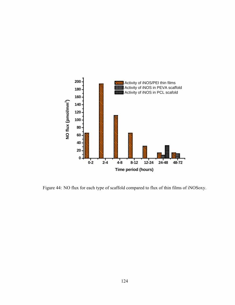
124
Figure 44: NO flux for each type of scaffold compared to flux of thin films of iNOSoxy.
0-2 2-4 4-8 8-12 12-24 24-48 48-720
20
40
60
80
100
120
140
160
180
200 Activity of iNOS/PEI thin films Activity of iNOS in PEVA scaffold Activity of iNOS in PCL scafold
NO
flu
x (p
mo
l/mm
2 )
Time period (hours)

125
3.4 Conclusion
This chapter describes the use of electrospinning method for fabricating iNOSoxy
embedded scaffolds and mats. NOS enzymes, particularly iNOS, can be used as an
antithrombogenic regimen in electrospun scaffolds and mats. As a preliminary step, we
have used PCL, PEVA and PVA for the encapsulation of iNOSoxy enzyme. The average
activity of iNOSoxy embedded in electrospun fibers described in this chapter is less than
the activity of LbL immobilized thin films described in chapter 1 and 2. Microscopic
images show successful encapsulation of iNOSoxy in aqueous pockets of microfibers,
showing increase of fiber diameter.
A combination of the thin film method and electrospun based encapsulation has the
potential to provide NO release to counteract thrombosis in applications requiring
immediate and delayed release of NO. We are now exploring the levels and extent to which
electrospun fibers with trapped NOS enzymes can sustain NO release under physiological
conditions.
126
3.5 Reference
1. Matthews, J.A., G.E. Wnek, D.G. Simpson, and G.L. Bowlin, Electrospinning of
collagen nanofibers. Biomacromolecules, 2002. 3(2): p. 232-8.
2. Wutticharoenmongkol, P., N. Sanchavanakit, P. Pavasant, and P. Supaphol,
Preparation and characterization of novel bone scaffolds based on electrospun
polycaprolactone fibers filled with nanoparticles. Macromol Biosci, 2006. 6(1): p.
70-7.
3. Boland, E.D., T.A. Telemeco, D.G. Simpson, G.E. Wnek, and G.L. Bowlin,
Utilizing acid pretreatment and electrospinning to improve biocompatibility of
poly(glycolic acid) for tissue engineering. Journal of Biomedical Materials
Research Part B: Applied Biomaterials, 2004. 71B(1): p. 144-152.
4. Telemeco, T.A., C. Ayres, G.L. Bowlin, G.E. Wnek, E.D. Boland, N. Cohen, C.M.
Baumgarten, J. Mathews, and D.G. Simpson, Regulation of cellular infiltration into
tissue engineering scaffolds composed of submicron diameter fibrils produced by
electrospinning. Acta Biomater, 2005. 1(4): p. 377-85.
5. Kenawy, E., G.L. Bowlin, K. Mansfield, J. Layman, D.G. Simpson, E.H. Sanders,
and G.E. Wnek, Release of tetracycline hydrochloride from electrospun
poly(ethylene-co-vinylacetate), poly(lactic acid), and a blend. Journal of
Controlled Release, 2002. 81(1–2): p. 57-64.
6. Son, W.K., J.H. Youk, T.S. Lee, and W.H. Park, Effect of pH on electrospinning of
poly(vinyl alcohol). Materials Letters, 2005. 59(12): p. 1571-1575.

127
7. Patel, A.C., S. Li, J.M. Yuan, and Y. Wei, In situ encapsulation of horseradish
peroxidase in electrospun porous silica fibers for potential biosensor applications.
Nano Lett, 2006. 6(5): p. 1042-6.
8. Luu, Y.K., K. Kim, B.S. Hsiao, B. Chu, and M. Hadjiargyrou, Development of a
nanostructured DNA delivery scaffold via electrospinning of PLGA and PLA–PEG
block copolymers. Journal of Controlled Release, 2003. 89(2): p. 341-353.
9. Garg, K. and G.L. Bowlin, Electrospinning jets and nanofibrous structures.
Biomicrofluidics, 2011. 5(1): p. -.
10. Bu, N., Y. Huang, Y. Duan, and Z. Yin, Process optimization of mechano-
electrospinning by response surface methodology. J Nanosci Nanotechnol, 2014.
14(5): p. 3464-72.
11. Jiang, H., Y. Hu, Y. Li, P. Zhao, K. Zhu, and W. Chen, A facile technique to prepare
biodegradable coaxial electrospun nanofibers for controlled release of bioactive
agents. Journal of Controlled Release, 2005. 108(2–3): p. 237-243.
12. Zhang, Y.Z., X. Wang, Y. Feng, J. Li, C.T. Lim, and S. Ramakrishna, Coaxial
electrospinning of (fluorescein isothiocyanate-conjugated bovine serum albumin)-
encapsulated poly(epsilon-caprolactone) nanofibers for sustained release.
Biomacromolecules, 2006. 7(4): p. 1049-57.
13. Jiang, H., D. Fang, B. Hsiao, B. Chu, and W. Chen, Preparation and
characterization of ibuprofen-loaded poly(lactide-co-glycolide)/poly(ethylene
glycol)-g-chitosan electrospun membranes. Journal of Biomaterials Science,
Polymer Edition, 2004. 15(3): p. 279-296.
128
14. Zeng, J., X. Xu, X. Chen, Q. Liang, X. Bian, L. Yang, and X. Jing, Biodegradable
electrospun fibers for drug delivery. Journal of Controlled Release, 2003. 92(3): p.
227-231.
15. Chew, S.Y., J. Wen, E.K.F. Yim, and K.W. Leong, Sustained Release of Proteins
from Electrospun Biodegradable Fibers. Biomacromolecules, 2005. 6(4): p. 2017-
2024.
16. Maretschek, S., A. Greiner, and T. Kissel, Electrospun biodegradable nanofiber
nonwovens for controlled release of proteins. Journal of Controlled Release, 2008.
127(2): p. 180-187.
17. Alhusein, N., I. Blagbrough, and P. Bank, Electrospun matrices for localised
controlled drug delivery: release of tetracycline hydrochloride from layers of
polycaprolactone and poly(ethylene-co-vinyl acetate). Drug Delivery and
Translational Research, 2012. 2(6): p. 477-488.
18. Li, L., Y. Qian, C. Jiang, Y. Lv, W. Liu, L. Zhong, K. Cai, S. Li, and L. Yang, The
use of hyaluronan to regulate protein adsorption and cell infiltration in
nanofibrous scaffolds. Biomaterials, 2012. 33(12): p. 3428-45.
19. Maheshwari, S., S. Kumar, N. Nagiah, and T. Uma, Electrospinning of
polyvinylalcohol–polycaprolactone composite scaffolds for tissue engineering
applications. Polymer Bulletin, 2013. 70(11): p. 2995-3010.
20. Song, W., X. Yu, D.C. Markel, T. Shi, and W. Ren, Coaxial PCL/PVA electrospun
nanofibers: osseointegration enhancer and controlled drug release device.
Biofabrication, 2013. 5(3): p. 035006.
129
21. Li, X., M.A. Kanjwal, L. Lin, and I.S. Chronakis, Electrospun polyvinyl-alcohol
nanofibers as oral fast-dissolving delivery system of caffeine and riboflavin.
Colloids Surf B Biointerfaces, 2013. 103: p. 182-8.
22. Stone, S.A., P. Gosavi, T.J. Athauda, and R.R. Ozer, In situ citric acid crosslinking
of alginate/polyvinyl alcohol electrospun nanofibers. Materials Letters, 2013.
112(0): p. 32-35.
23. Yao, L., T.W. Haas, A. Guiseppi-Elie, G.L. Bowlin, D.G. Simpson, and G.E. Wnek,
Electrospinning and Stabilization of Fully Hydrolyzed Poly(Vinyl Alcohol) Fibers.
Chemistry of Materials, 2003. 15(9): p. 1860-1864.
24. Shaikh, R.P., P. Kumar, Y.E. Choonara, L.C. du Toit, and V. Pillay, Crosslinked
electrospun PVA nanofibrous membranes: elucidation of their physicochemical,
physicomechanical and molecular disposition. Biofabrication, 2012. 4(2): p.
025002.
25. Defrere, S., M. Mestagdt, R. Riva, F. Krier, A. Van Langendonckt, P. Drion, C.
Jerome, B. Evrard, J.P. Dehoux, J.M. Foidart, and J. Donnez, In vivo
biocompatibility of three potential intraperitoneal implants. Macromol Biosci,
2011. 11(10): p. 1336-45.
26. Lefevre-Groboillot, D., J.L. Boucher, D. Mansuy, and D.J. Stuehr, Reactivity of the
heme-dioxygen complex of the inducible nitric oxide synthase in the presence of
alternative substrates. Febs j, 2006. 273(1): p. 180-91.
130
27. Pufahl, R.A., J.S. Wishnok, and M.A. Marletta, Hydrogen Peroxide-Supported
Oxidation of NG-Hydroxy-L-Arginine by Nitric Oxide Synthase. Biochemistry,
1995. 34(6): p. 1930-1941.
28. Sheng, J.Z., D. Wang, and A.P. Braun, DAF-FM (4-amino-5-methylamino-2',7'-
difluorofluorescein) diacetate detects impairment of agonist-stimulated nitric oxide
synthesis by elevated glucose in human vascular endothelial cells: reversal by
vitamin C and L-sepiapterin. J Pharmacol Exp Ther, 2005. 315(2): p. 931-40.
29. Diez, I., S. Calatayud, C. Hernandez, E. Quintana, J.E. O'Connor, J.V. Esplugues,
and M.D. Barrachina, Nitric oxide, derived from inducible nitric oxide synthase,
decreases hypoxia inducible factor-1alpha in macrophages during aspirin-induced
mesenteric inflammation. Br J Pharmacol, 2010. 159(8): p. 1636-45.
30. Baron, M.H., Revault, M., Servagent-Noinville, S., Abadie, J., Quiquampoix, H.,
Chymotrypsin adsorption on Montmorillonite: Enzymatic activity and kinetic FTIR
structural analysis. Journal of Colloid and Interface Science, 1999. 214(2): p. 319-
332.
31. Venyaminov, S. and N.N. Kalnin, Quantitative IR spectrophotometry of peptide
compounds in water (H2O) solutions. I. Spectral parameters of amino acid residue
absorption bands. Biopolymers, 1990. 30(13-14): p. 1243-57.
32. Krimm, S. and J. Bandekar, Vibrational spectroscopy and conformation of
peptides, polypeptides, and proteins. Adv Protein Chem, 1986. 38: p. 181-364.
33. Nevskaya, N.A. and Y.N. Chirgadze, Infrared spectra and resonance interactions
of amide-I and II vibration of alpha-helix. Biopolymers, 1976. 15(4): p. 637-48.

131
34. Klibanov, A.M., Improving enzymes by using them in organic solvents. Nature,
2001. 409(6817): p. 241-246.
35. Li, C., R. Fu, C. Yu, Z. Li, H. Guan, D. Hu, D. Zhao, and L. Lu, Silver
nanoparticle/chitosan oligosaccharide/poly(vinyl alcohol) nanofibers as wound
dressings: a preclinical study. Int J Nanomedicine, 2013. 8: p. 4131-45.
36. Manasco, J.L., C. Tang, N.A. Burns, C.D. Saquing, and S.A. Khan, Rapidly
dissolving poly(vinyl alcohol)/cyclodextrin electrospun nanofibrous membranes.
RSC Advances, 2014. 4(26): p. 13274-13279.
37. Ramalingam, M., M.F. Young, V. Thomas, L. Sun, L.C. Chow, C.K. Tison, K.
Chatterjee, W.C. Miles, and C.G. Simon, Jr., Nanofiber scaffold gradients for
interfacial tissue engineering. J Biomater Appl, 2013. 27(6): p. 695-705.
38. Gök, E. and S. Olgaz, Binding of Fluorescein Isothiocyanate to Insulin: A
Fluorimetric Labeling Study. Journal of Fluorescence, 2004. 14(2): p. 203-206.
39. Majima, E., M. Ishida, S. Miki, Y. Shinohara, and H. Terada, Specific Labeling of
the Bovine Heart Mitochondrial Phosphate Carrier with Fluorescein 5-
Isothiocyanate: ROLES OF LYS185 AND PUTATIVE ADENINE NUCLEOTIDE
RECOGNITION SITE IN PHOSPHATE TRANSPORT. Journal of Biological
Chemistry, 2001. 276(13): p. 9792-9799.
40. Haynie, D.T., D.B. Khadka, and M.C. Cross, Physical Properties of Polypeptide
Electrospun Nanofiber Cell Culture Scaffolds on a Wettable Substrate. Polymers,
2012. 4(3): p. 1535-1553.

132
41. Sant, S., C.M. Hwang, S.-H. Lee, and A. Khademhosseini, Hybrid PGS–PCL
microfibrous scaffolds with improved mechanical and biological properties.
Journal of Tissue Engineering and Regenerative Medicine, 2011. 5(4): p. 283-291.