Embed Size (px)
Citation preview
National Aeronautics and Space Administration
www.nasa.gov
Environmentally Responsible Aviation Project: Infrastructure Enhancements and New Capabilities
AIAA SCITECHKissimmee, FLJanuary 5, 2015
Presenter: Gaudy M. Bezos-OConnorDeputy Project ManagerEnvironmentally Responsible Aviation ProjectIntegrated Systems Research Program/NASA Aeronautics Research Mission Directorate
https://ntrs.nasa.gov/search.jsp?R=20160006922 2020-04-19T13:56:03+00:00Z
Outline
• Introduction and Purpose• Langley COLTS• Armstrong SCRAT• Glenn Open Rotor Rig• Glenn Advanced Subsonic Combustor Rig• Glenn Balance Development for UHB Engine Testing• Glenn Compressor Rig• Langley 14x22 Acoustic and Hot Jet Capabilities• Langley Microphone Array for Use with Flying Testbeds• Summary Remarks
2
Introduction and Purpose
3
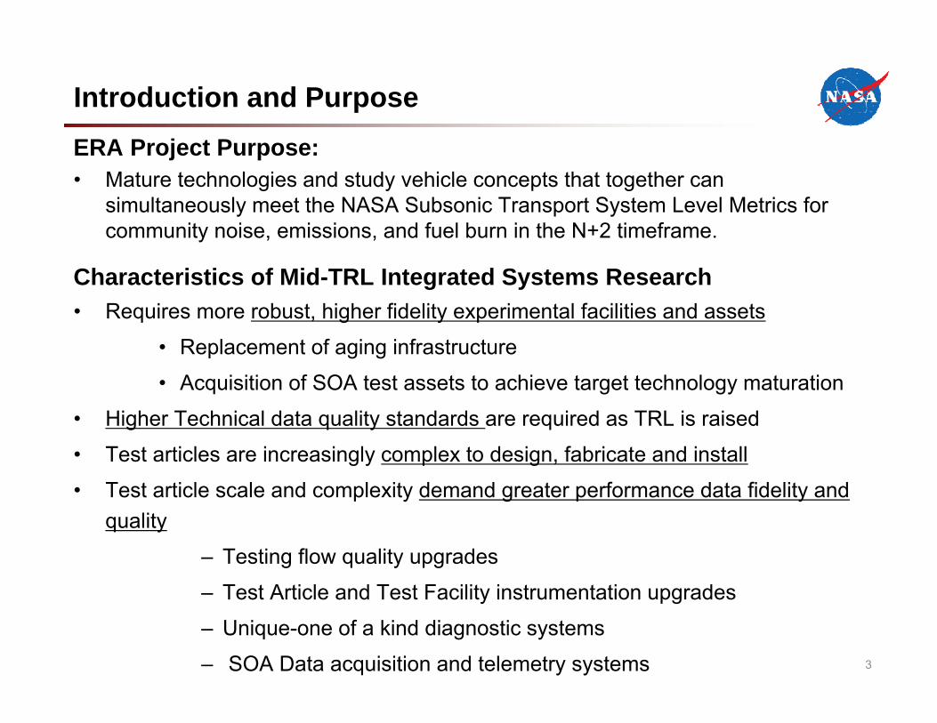
ERA Project Purpose:• Mature technologies and study vehicle concepts that together can
simultaneously meet the NASA Subsonic Transport System Level Metrics for community noise, emissions, and fuel burn in the N+2 timeframe.
Characteristics of Mid-TRL Integrated Systems Research• Requires more robust, higher fidelity experimental facilities and assets
• Replacement of aging infrastructure
• Acquisition of SOA test assets to achieve target technology maturation
• Higher Technical data quality standards are required as TRL is raised
• Test articles are increasingly complex to design, fabricate and install
• Test article scale and complexity demand greater performance data fidelity and quality
– Testing flow quality upgrades
– Test Article and Test Facility instrumentation upgrades
– Unique-one of a kind diagnostic systems
– SOA Data acquisition and telemetry systems
Introduction and Purpose
4
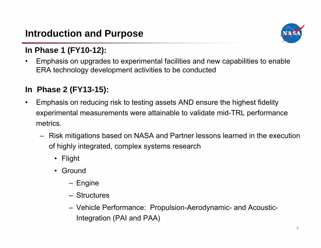
In Phase 1 (FY10-12):• Emphasis on upgrades to experimental facilities and new capabilities to enable
ERA technology development activities to be conducted
In Phase 2 (FY13-15):• Emphasis on reducing risk to testing assets AND ensure the highest fidelity
experimental measurements were attainable to validate mid-TRL performance metrics.
– Risk mitigations based on NASA and Partner lessons learned in the execution of highly integrated, complex systems research
• Flight
• Ground
– Engine
– Structures
– Vehicle Performance: Propulsion-Aerodynamic- and Acoustic-Integration (PAI and PAA)
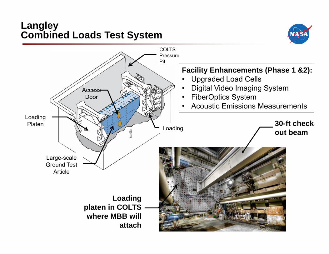
Upper
Section
Large-scale Ground Test
Article
Loading Platen
Loading
COLTS Pressure Pit
Access Door
Loadingplaten in COLTS where MBB will
attach
30-ft check out beam
Langley Combined Loads Test System
Facility Enhancements (Phase 1 &2):• Upgraded Load Cells • Digital Video Imaging System• FiberOptics System• Acoustic Emissions Measurements
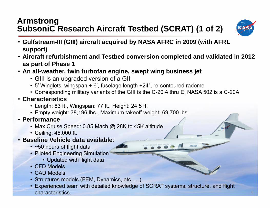
Armstrong SubsoniC Research Aircraft Testbed (SCRAT) (1 of 2)• Gulfstream-III (GIII) aircraft acquired by NASA AFRC in 2009 (with AFRL
support) • Aircraft refurbishment and Testbed conversion completed and validated in 2012
as part of Phase 1• An all-weather, twin turbofan engine, swept wing business jet
• GIII is an upgraded version of a GII• 5’ Winglets, wingspan + 6’, fuselage length +24”, re-contoured radome• Corresponding military variants of the GIII is the C-20 A thru E; NASA 502 is a C-20A
• Characteristics• Length: 83 ft., Wingspan: 77 ft., Height: 24.5 ft.• Empty weight: 38,196 lbs., Maximum takeoff weight: 69,700 lbs.
• Performance• Max Cruise Speed: 0.85 Mach @ 28K to 45K altitude• Ceiling: 45,000 ft.
• Baseline Vehicle data available:• ~50 hours of flight data• Piloted Engineering Simulation
• Updated with flight data• CFD Models• CAD Models• Structures models (FEM, Dynamics, etc. …)• Experienced team with detailed knowledge of SCRAT systems, structure, and flight
characteristics. 6
Features/Capabilities (Phase 2):• Flight Research Instrumentation System
•Fiber Optic Strain Sensing (FOSS)•AirData Parameters•EGI – New with the ACTE flights•Wing Pressures•Leading Edge Hotfilm Data•Wing Strain Gage Data•Structural Accelerometers•Control Surface Positions
• Telemetry System installed on SCRAT.
• Power System modified.
• Cabin can be reconfigurable and allows for researchers to fly with their experiments
• Crew – 3 (2 Pilots & Flight Test Engineer), passengers – up to 3
• Aircraft extensively characterized.
Benefits:GIII is capable of supporting a wide range
of aeronautics related research.
Instrumentation System and Sensors will provide high quality flight data suitable for conducting flight research
Allows for control room monitoring during envelope expansion for additional researchers to monitor research flights
Power System flexible enough to allow for future research experiments
Cabin can be configured to accommodate a wide range of flight experiments.
Researchers can fly along with their experiments and monitor progress real-time without the need for a control room.
NASA has a SOA subsonic transport class testbed aircraft for developing aeronautics technologies. 7
ArmstrongSubsoniC Research Aircraft Testbed (SCRAT) (2 of 2)
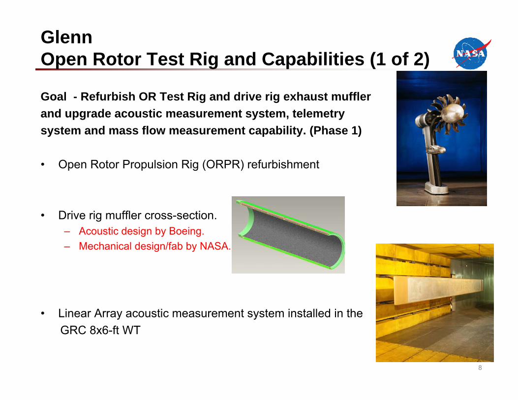
Goal - Refurbish OR Test Rig and drive rig exhaust muffler and upgrade acoustic measurement system, telemetrysystem and mass flow measurement capability. (Phase 1)
• Open Rotor Propulsion Rig (ORPR) refurbishment
• Drive rig muffler cross-section. – Acoustic design by Boeing. – Mechanical design/fab by NASA.
• Linear Array acoustic measurement system installed in theGRC 8x6-ft WT
8
GlennOpen Rotor Test Rig and Capabilities (1 of 2)
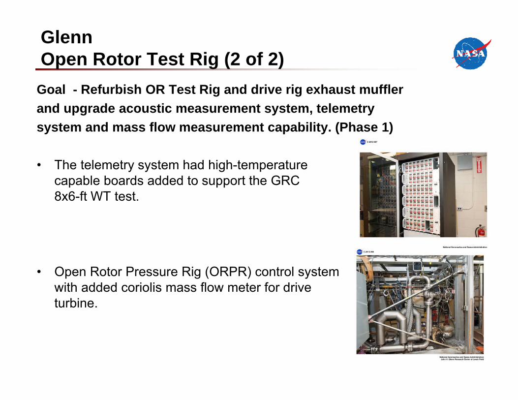
Goal - Refurbish OR Test Rig and drive rig exhaust muffler and upgrade acoustic measurement system, telemetrysystem and mass flow measurement capability. (Phase 1)
• The telemetry system had high-temperature capable boards added to support the GRC 8x6-ft WT test.
• Open Rotor Pressure Rig (ORPR) control system with added coriolis mass flow meter for drive turbine.
GlennOpen Rotor Test Rig (2 of 2)
GlennASCR Facility Improvements (1 of 2)
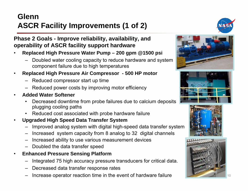
Phase 2 Goals - Improve reliability, availability, and operability of ASCR facility support hardware• Replaced High Pressure Water Pump – 200 gpm @1500 psi
– Doubled water cooling capacity to reduce hardware and system component failure due to high temperatures
• Replaced High Pressure Air Compressor - 500 HP motor– Reduced compressor start up time– Reduced power costs by improving motor efficiency
• Added Water Softener• Decreased downtime from probe failures due to calcium deposits
plugging cooling paths• Reduced cost associated with probe hardware failure
• Upgraded High Speed Data Transfer System– Improved analog system with digital high-speed data transfer system– Increased system capacity from 8 analog to 32 digital channels – Increased ability to use various measurement devices– Doubled the data transfer speed
• Enhanced Pressure Sensing Platform– Integrated 75 high accuracy pressure transducers for critical data.– Decreased data transfer response rates– Increase operator reaction time in the event of hardware failure 10
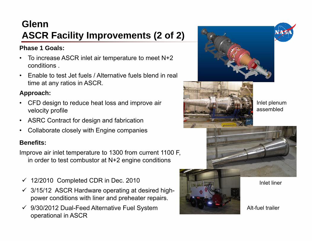
Phase 1 Goals: • To increase ASCR inlet air temperature to meet N+2
conditions . • Enable to test Jet fuels / Alternative fuels blend in real
time at any ratios in ASCR. Approach:• CFD design to reduce heat loss and improve air
velocity profile• ASRC Contract for design and fabrication • Collaborate closely with Engine companies
Benefits: Improve air inlet temperature to 1300 from current 1100 F,
in order to test combustor at N+2 engine conditions
12/2010 Completed CDR in Dec. 2010 3/15/12 ASCR Hardware operating at desired high-
power conditions with liner and preheater repairs. 9/30/2012 Dual-Feed Alternative Fuel System
operational in ASCRAlt-fuel trailer
Inlet liner
Inlet plenumassembled
GlennASCR Facility Improvements (2 of 2)
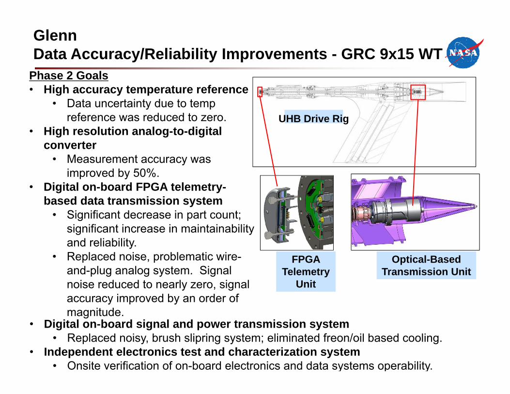
Phase 2 Goals• High accuracy temperature reference
• Data uncertainty due to temp reference was reduced to zero.
• High resolution analog-to-digital converter
• Measurement accuracy was improved by 50%.
• Digital on-board FPGA telemetry-based data transmission system
• Significant decrease in part count; significant increase in maintainability and reliability.
• Replaced noise, problematic wire-and-plug analog system. Signal noise reduced to nearly zero, signal accuracy improved by an order of magnitude.
GlennData Accuracy/Reliability Improvements - GRC 9x15 WT
Final image will show individual parts and names
Optical-Based Transmission Unit
FPGA Telemetry
Unit
UHB Drive Rig
• Digital on-board signal and power transmission system• Replaced noisy, brush slipring system; eliminated freon/oil based cooling.
• Independent electronics test and characterization system• Onsite verification of on-board electronics and data systems operability.
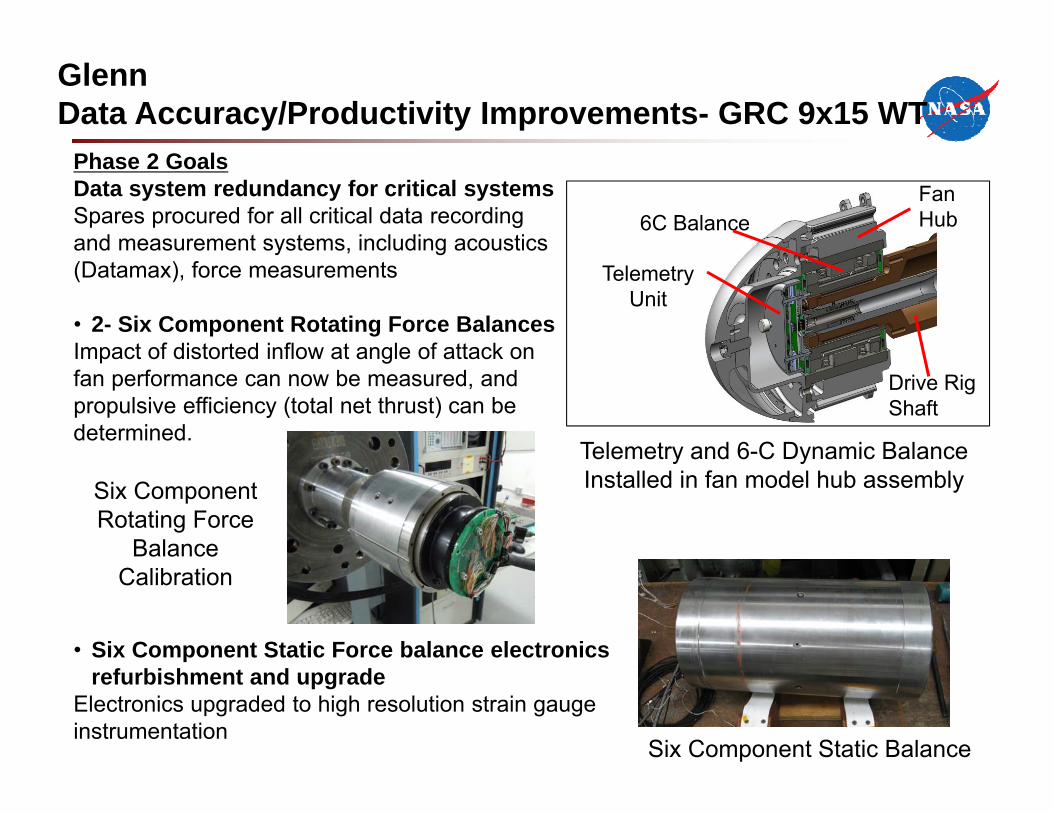
Phase 2 GoalsData system redundancy for critical systemsSpares procured for all critical data recording and measurement systems, including acoustics (Datamax), force measurements
• 2- Six Component Rotating Force BalancesImpact of distorted inflow at angle of attack on fan performance can now be measured, and propulsive efficiency (total net thrust) can be determined.
• Six Component Static Force balance electronics refurbishment and upgrade
Electronics upgraded to high resolution strain gauge instrumentation
GlennData Accuracy/Productivity Improvements- GRC 9x15 WT
Six Component Rotating Force
Balance Calibration
Fan Hub6C Balance
TelemetryUnit
Drive Rig Shaft
Six Component Static Balance
Telemetry and 6-C Dynamic Balance Installed in fan model hub assembly
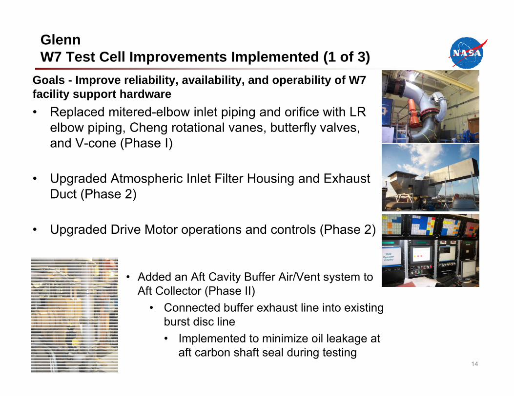
GlennW7 Test Cell Improvements Implemented (1 of 3)
Goals - Improve reliability, availability, and operability of W7 facility support hardware• Replaced mitered-elbow inlet piping and orifice with LR
elbow piping, Cheng rotational vanes, butterfly valves, and V-cone (Phase I)
• Upgraded Atmospheric Inlet Filter Housing and Exhaust Duct (Phase 2)
• Upgraded Drive Motor operations and controls (Phase 2)
• Added an Aft Cavity Buffer Air/Vent system to Aft Collector (Phase II)
• Connected buffer exhaust line into existing burst disc line• Implemented to minimize oil leakage at
aft carbon shaft seal during testing14
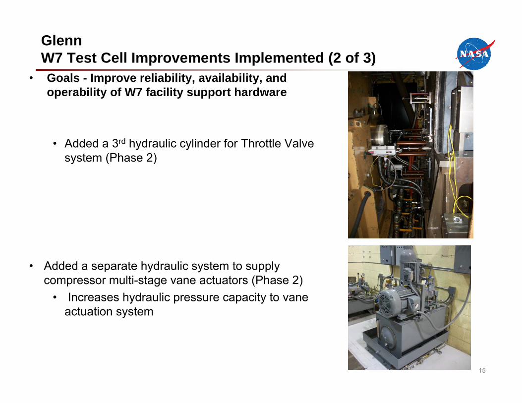
• Goals - Improve reliability, availability, and operability of W7 facility support hardware
• Added a 3rd hydraulic cylinder for Throttle Valve system (Phase 2)
• Added a separate hydraulic system to supply compressor multi-stage vane actuators (Phase 2)
• Increases hydraulic pressure capacity to vane actuation system
15
GlennW7 Test Cell Improvements Implemented (2 of 3)
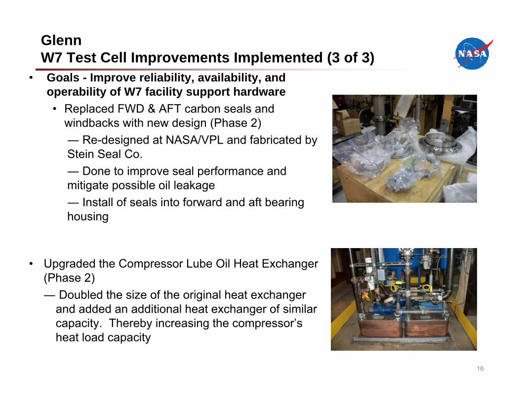
• Goals - Improve reliability, availability, and operability of W7 facility support hardware• Replaced FWD & AFT carbon seals and
windbacks with new design (Phase 2)― Re-designed at NASA/VPL and fabricated by Stein Seal Co.― Done to improve seal performance and mitigate possible oil leakage― Install of seals into forward and aft bearing housing
• Upgraded the Compressor Lube Oil Heat Exchanger (Phase 2)― Doubled the size of the original heat exchanger
and added an additional heat exchanger of similar capacity. Thereby increasing the compressor’s heat load capacity
16
GlennW7 Test Cell Improvements Implemented (3 of 3)
17
LangleyAero-Acoustic Testing Capability for 14x22-ft WT (1 of 6)
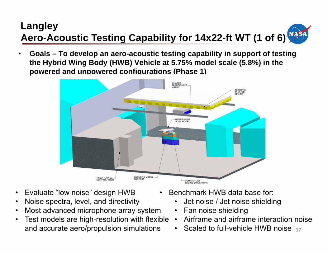
• Goals – To develop an aero-acoustic testing capability in support of testing the Hybrid Wing Body (HWB) Vehicle at 5.75% model scale (5.8%) in the powered and unpowered configurations (Phase 1)
• Evaluate “low noise” design HWB• Noise spectra, level, and directivity • Most advanced microphone array system• Test models are high-resolution with flexible
and accurate aero/propulsion simulations
• Benchmark HWB data base for: • Jet noise / Jet noise shielding• Fan noise shielding• Airframe and airframe interaction noise• Scaled to full-vehicle HWB noise
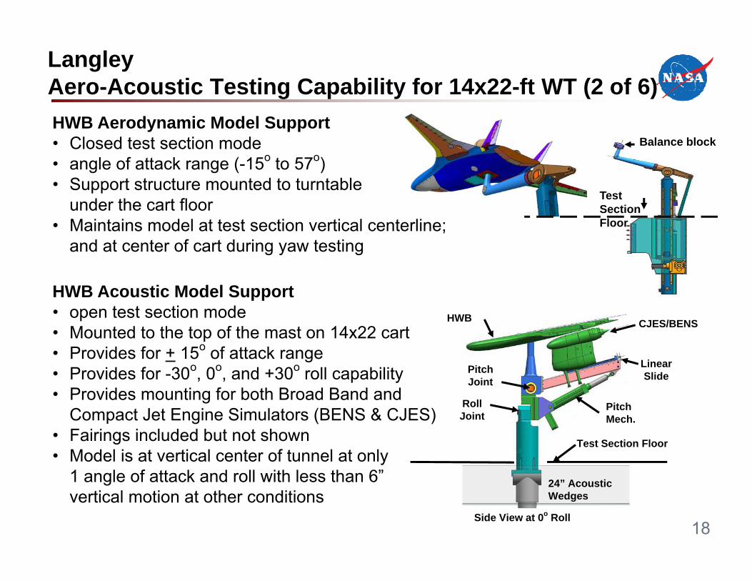
HWB Aerodynamic Model Support• Closed test section mode• angle of attack range (-15o to 57o)• Support structure mounted to turntable
under the cart floor• Maintains model at test section vertical centerline;
and at center of cart during yaw testing
HWB Acoustic Model Support• open test section mode• Mounted to the top of the mast on 14x22 cart• Provides for + 15o of attack range• Provides for -30o, 0o, and +30o roll capability• Provides mounting for both Broad Band and
Compact Jet Engine Simulators (BENS & CJES)• Fairings included but not shown• Model is at vertical center of tunnel at only
1 angle of attack and roll with less than 6” vertical motion at other conditions
Balance block
Test Section Floor
18
LangleyAero-Acoustic Testing Capability for 14x22-ft WT (2 of 6)
Pitch Mech.
LinearSlide
CJES/BENSHWB
Pitch Joint
Roll Joint
24” Acoustic Wedges
Test Section Floor
Side View at 0o Roll
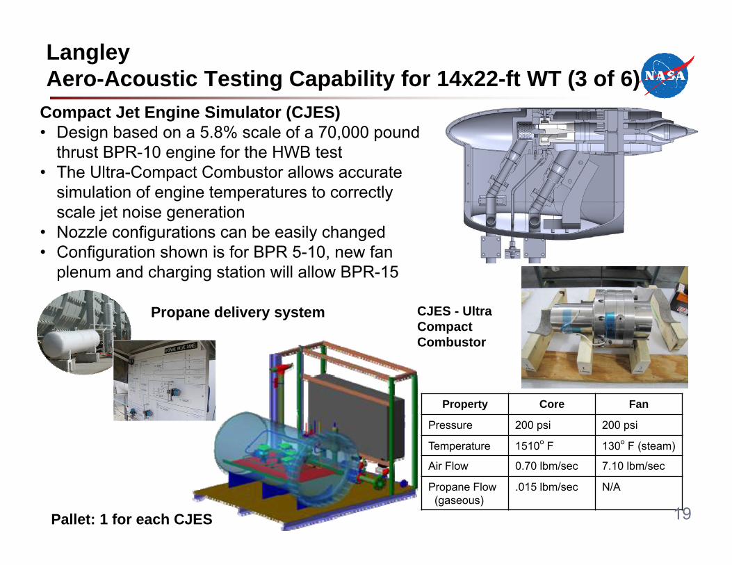
Compact Jet Engine Simulator (CJES)• Design based on a 5.8% scale of a 70,000 pound
thrust BPR-10 engine for the HWB test• The Ultra-Compact Combustor allows accurate
simulation of engine temperatures to correctly scale jet noise generation
• Nozzle configurations can be easily changed• Configuration shown is for BPR 5-10, new fan
plenum and charging station will allow BPR-15
Property Core Fan
Pressure 200 psi 200 psi
Temperature 1510o F 130o F (steam)
Air Flow 0.70 lbm/sec 7.10 lbm/sec
Propane Flow(gaseous)
.015 lbm/sec N/A
CJES - Ultra Compact Combustor
19
LangleyAero-Acoustic Testing Capability for 14x22-ft WT (3 of 6)
Propane delivery system
Pallet: 1 for each CJES
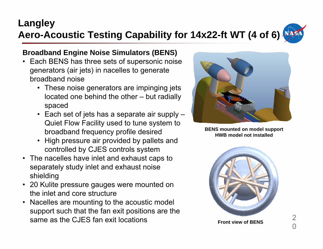
Broadband Engine Noise Simulators (BENS)• Each BENS has three sets of supersonic noise
generators (air jets) in nacelles to generate broadband noise
• These noise generators are impinging jets located one behind the other – but radially spaced
• Each set of jets has a separate air supply –Quiet Flow Facility used to tune system to broadband frequency profile desired
• High pressure air provided by pallets and controlled by CJES controls system
• The nacelles have inlet and exhaust caps to separately study inlet and exhaust noise shielding
• 20 Kulite pressure gauges were mounted on the inlet and core structure
• Nacelles are mounting to the acoustic model support such that the fan exit positions are the same as the CJES fan exit locations Front view of BENS
BENS mounted on model supportHWB model not installed
20
LangleyAero-Acoustic Testing Capability for 14x22-ft WT (4 of 6)
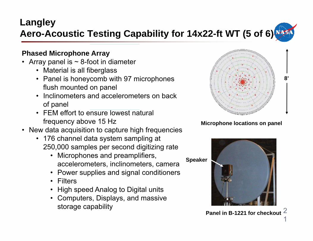
Phased Microphone Array• Array panel is ~ 8-foot in diameter
• Material is all fiberglass• Panel is honeycomb with 97 microphones
flush mounted on panel• Inclinometers and accelerometers on back
of panel • FEM effort to ensure lowest natural
frequency above 15 Hz• New data acquisition to capture high frequencies
• 176 channel data system sampling at 250,000 samples per second digitizing rate
• Microphones and preamplifiers, accelerometers, inclinometers, camera
• Power supplies and signal conditioners• Filters• High speed Analog to Digital units• Computers, Displays, and massive
storage capabilityPanel in B-1221 for checkout
Speaker
Microphone locations on panel
8’
21
LangleyAero-Acoustic Testing Capability for 14x22-ft WT (5 of 6)
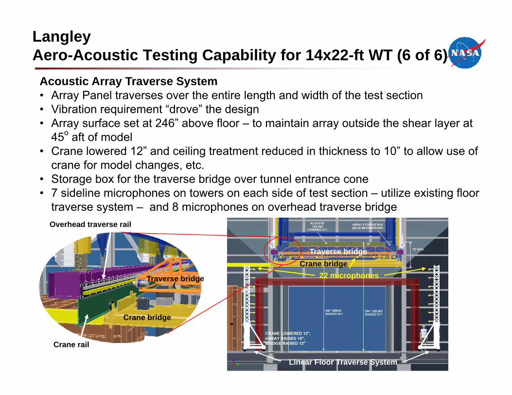
Acoustic Array Traverse System• Array Panel traverses over the entire length and width of the test section• Vibration requirement “drove” the design• Array surface set at 246” above floor – to maintain array outside the shear layer at
45o aft of model• Crane lowered 12” and ceiling treatment reduced in thickness to 10” to allow use of
crane for model changes, etc.• Storage box for the traverse bridge over tunnel entrance cone • 7 sideline microphones on towers on each side of test section – utilize existing floor
traverse system – and 8 microphones on overhead traverse bridge
Crane rail
Overhead traverse rail
22 microphones
Linear Floor Traverse System
Crane bridge
Crane bridge
Traverse bridge
Traverse bridge
LangleyAero-Acoustic Testing Capability for 14x22-ft WT (6 of 6)
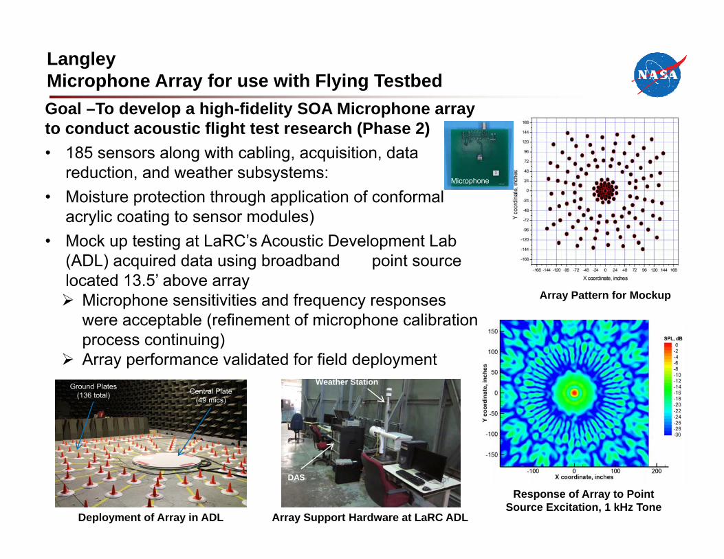
LangleyMicrophone Array for use with Flying TestbedGoal –To develop a high-fidelity SOA Microphone array to conduct acoustic flight test research (Phase 2)• 185 sensors along with cabling, acquisition, data
reduction, and weather subsystems:• Moisture protection through application of conformal
acrylic coating to sensor modules)• Mock up testing at LaRC’s Acoustic Development Lab
(ADL) acquired data using broadband point source located 13.5’ above array Microphone sensitivities and frequency responses
were acceptable (refinement of microphone calibration process continuing)
Array performance validated for field deployment
Deployment of Array in ADL
PIV/LV test setup
Quiet flap (FLEXSEL)
BaselineWeather Station
DAS
Array Support Hardware at LaRC ADL
Array Pattern for Mockup
Response of Array to PointSource Excitation, 1 kHz Tone
Microphone
Central Plate(49 mics)
Ground Plates(136 total)
Summary Remarks
• The ERA Project has invested in the development of SOA test capabilities and infrastructure that enabled technology maturation of critical airframe and propulsion technologies
• We are poised in Phase 2 to advance the TRL and accelerate the technology insertion of the ITD airframe and propulsion technologies into the 2025 fleet of aircraft.
• As ERA concludes the resultant Legacy to ARMD’s Programs, Centers, Industry and Government Partners:– Infrastructure Enhancements
– New Test Capabilities
– Enhanced Modeling and Tool Development
– New/Updated Experimental Databases
– Enriched/Enhanced Workforce Competencies
Paints a very bright and green future to achieving our Carbon Neutral National Aviation Goals
24