Embed Size (px)
Citation preview
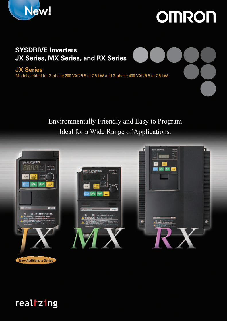
Environmentally Friendly and Easy to Program
Ideal for a Wide Range of Applications.
SYSDRIVE Inverters
JX Series, MX Series, and RX Series
JX SeriesModels added for 3-phase 200 VAC 5.5 to 7.5 kW and 3-phase 400 VAC 5.5 to 7.5 kW.
New Additions to Series

Introducing New, General-purpose SYSDRIVE Inverters from OMRON.
Three Concepts and Three Series Provide the Optimal Selection.
3
Selection
Capacity............................................
Functions...........................................
Features
Kind to the Environment.................
Kind to People..................................
Versatile in Application..................
SYSDRIVE JX Series.......................
Nomenclature and Functions......
Using Digital Operator...................
Standard Specification List..........
Dimensions......................................
Standard Connection Diagram....
Protective and Diagnostic Functions.........................................
Model Number Explanation.........
Standard Models...........................
SYSDRIVE MX Series.....................
Nomenclature and Functions......
Using Digital Operator...................
Standard Specification List..........
Dimensions.....................................
Standard Connection Diagram....
Protective and Diagnostic Functions.........................................
Model Number Explanation.........
Standard Models...........................
SYSDRIVE RX Series.......................
Nomenclature and Functions......
Using Digital Operator..................
Standard Specification List.........
Dimensions.....................................
Standard Connection Diagram....
Protective and Diagnostic Functions.........................................
Model Number Explanation.........
Standard Models...........................
SYSDRIVE Option...........................
Overview of Inverter Selection...
Environmentally FriendlyThe use of long-life consumables, such as capacitors and fans, extends the life of the Inverter (in comparison to previous models). We also gave ample consideration to the lifetime and energy-saving capability of connected motors, and provided full compliance with the RoHS Directive and other international standards, all as standard features.
Versatile in ApplicationAll models meet today's demands for increased performance and advanced functions in General-purpose Inverters, and offer greater versatility in application. From simple models that focus on ease of use to multi-functional and advanced models that are designed to handle diverse applications, a full complement of functions have been provided to ensure optimal performance in meeting various needs.
Easy to UseEase of use was given top priority to help reduce thenumber of overall steps required to use OMRON's Generalpurpose Inverters, starting with wiring and settingparameters and extending to onsite maintenance andadjustments. A wide range offunctions is also included toreduce the total cost ofownership (TCO) for the entiresystem. This further reflects our pursuit of customer satisfaction.
Environmentally friendly and easy-to-use Inverters for simple applications. Environmentally
friendly and easy-to-use multi-functional Inverters.
New Advanced Inverters that handle diverse applications while remaining environmentally friendly and easy to use.
Simple, Compact InvertersSYSDRIVE JX Series
Multi-functional, Compact InvertersSYSDRIVE MX Series
Advanced General-purpose Inverters
SYSDRIVE RX Series
4
5
6
7
8
10
10
12
14
19
21
22
23
23
24
24
26
28
33
35
36
37
37
38
38
40
42
48
50
51
53
53
54
58
5
Selection Based on Functions Specifications
Capacity
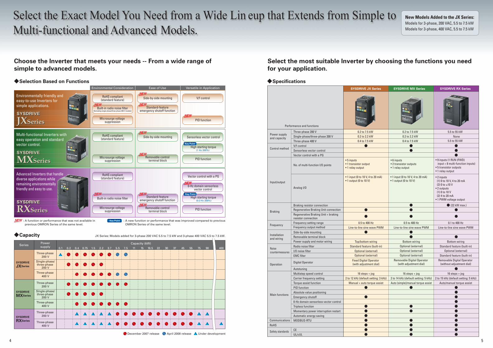
Choose the Inverter that meets your needs -- From a wide range of
simple to advanced models.
Select the most suitable Inverter by choosing the functions you need
for your application.
Environmental Consideration Ease of Use Versatile in Application
Braking resistor connection
Frequency setting rangeFrequency output method
Regenerative Braking Unit connectionRegenerative Braking Unit + braking resistor connection
Side-by-side mountingRemovable terminal blockPower supply and motor wiring
Radio noise filterI/O noise filterEMC filter
Digital Operator
AutotuningMultistep speed controlCarrier frequency settingTorque assist functionPID functionAbsolute value positioningEmergency shutoff0-Hz domain sensorless vector controlTripless functionMomentary power interruption restartAutomatic energy savingMODBUS-RTU
RoHSCEUL/cUL
Braking
Frequency
Installation and wiring
Noise countermeasures
Operation
Main functions
Communications
Safety standards
Three-phase 200 VSingle-phase/three-phase 200 VThree-phase 400 VV/f controlSensorless vector controlVector control with a PG
Performance and functions
No. of multi-function I/O points
Analog I/O
None
Bottom wiring
Auto/manual torque assist
Bottom wiring
Auto (simple)/manual torque assist
• 5 inputs• 1 transistor output• 1 relay output
• 1 input (0 to 10 V, 4 to 20 mA)• 1 output (0 to 10 V)
• 1 input (0 to 10 V, 4 to 20 mA)• 1 output (0 to 10 V)
• 6 inputs• 2 transistor outputs• 1 relay output
• 9 inputs (1 RUN (FWD) input + 8 multi-function inputs) • 5 transistor outputs• 1 relay output
• 2 inputs (1) 0 to 10 V, 4 to 20 mA (2) 0 to ±10 V• 2 outputs (1) 0 to 10 V (2) 4 to 20 mA• 1 PWM voltage output
0.2 to 7.5 kW 0.2 to 7.5 kW 5.5 to 55 kW
5.5 to 55 kW0.4 to 7.5 kW0.2 to 2.2 kW
0.4 to 7.5 kW0.2 to 2.2 kW
0.5 to 400 Hz 0.5 to 400 Hz 0.1 to 400 HzLine-to-line sine wave PWM Line-to-line sine wave PWM Line-to-line sine wave PWM
Top/bottom wiringStandard feature (built-in) Standard feature (built-in)
Standard feature (built-in)Optional (external)
Optional (external)Optional (external) Optional (external)Optional (external)
Removable Digital Operator (with adjustment dial)
Removable Digital Operator (without adjustment dial)
Optional (external)
Fixed Digital Operator (with adjustment dial)
16 steps + jog 16 steps + jog 16 steps + jog2 to 12 kHz (default setting: 3 kHz) 2 to 14 kHz (default setting: 5 kHz) 2 to 15 kHz (default setting: 5 kHz)
Manual + auto torque assist
(1 Hz 200%)
Key Point
Key Point
Key Point
Three-phase 200 V
Three-phase 200 V
Three-phase 400 V
Single-phase/three-phase
200 V
Three-phase 200 V
Three-phase 400 V
Three-phase 400 V
Single-phase/three-phase
200 V
0.1 0.2 0.4 0.75 1.5 2.2 3.7 5.5 7.5 11 15 18.5 22 30 37 45 55 75 90 400
Power supply and capacity
Control method
Input/output
4
Select the Exact Model You Need from a Wide Lin eup that Extends from Simple to
Multi-functional and Advanced Models.
Environmentally friendly and easy-to-use Inverters for simple applications.
Multi-functional Inverters with easy operation and standard vector control.
Advanced Inverters that handle diverse applications while remaining environmentally friendly and easy to use.
RoHS compliant(standard feature)
RoHS compliant(standard feature)
RoHS compliant(standard feature)
Side-by-side mounting
Side-by-side mounting
V/f control
PID function
PID function
PID function
Standard-feature emergency shutoff function
Sensorless vector control
Vector control with a PG
0-Hz domain sensorless vector control
High starting torque
(0.3 Hz 200%)High starting torque
Removable control terminal block
Removable control terminal block
Standard-feature emergency shutoff function
Microsurge voltage suppression
Microsurge voltage suppression
Microsurge voltage suppression
Built-in radio noise filter(Excluding single-phase/three-phase 200-V models)
Built-in radio noise filter
: A function or performance that was not available in previous OMRON Series of the same level.
: A new function or performance that was improved compared to previous OMRON Series of the same level.
SeriesPowersupply
Capacity (kW)
SYSDRIVE
MXSeries
SYSDRIVE
JXSeries
SYSDRIVE
RXSeries
December 2007 release April 2008 release Under development
SYSDRIVE MX SeriesSYSDRIVE JX Series SYSDRIVE RX Series
(22 kW max.)
JX Series: Models added for 3-phase 200 VAC 5.5 to 7.5 kW and 3-phase 400 VAC 5.5 to 7.5 kW.
New Models Added to the JX Series: Models for 3-phase, 200 VAC, 5.5 to 7.5 kWModels for 3-phase, 400 VAC, 5.5 to 7.5 kW
Standard Compliance with the RoHS Directive and Other International Standards Noise Measures for Peripheral Equipment Side-by-side Mounting Saves Space Emergency Shutoff Function
Removable Digital Operator (Standard Feature)
Easy Parameter Setting
Removable Control Terminal Block
6 7
240 mm
324 mm
30 mm 30 mm 30 mm 30 mm
84 mm of space
saved
1,250 V
• RoHS
•International Standards
PBDE
PBBCdPb
Hg Cr6+
Microsurge Voltage Suppression
Automatic Energy-saving Function
Long-life Design
100
90
80
70
60
50
40
30
20
10
010 20 30 40 50 60 70 80 90 100
Energy-saving
effect
Damper suppression76 %
91 %
61 %
22 %
IGBT gate
Latch
Set
Interruption
EMR
Reset
Power supply circuit
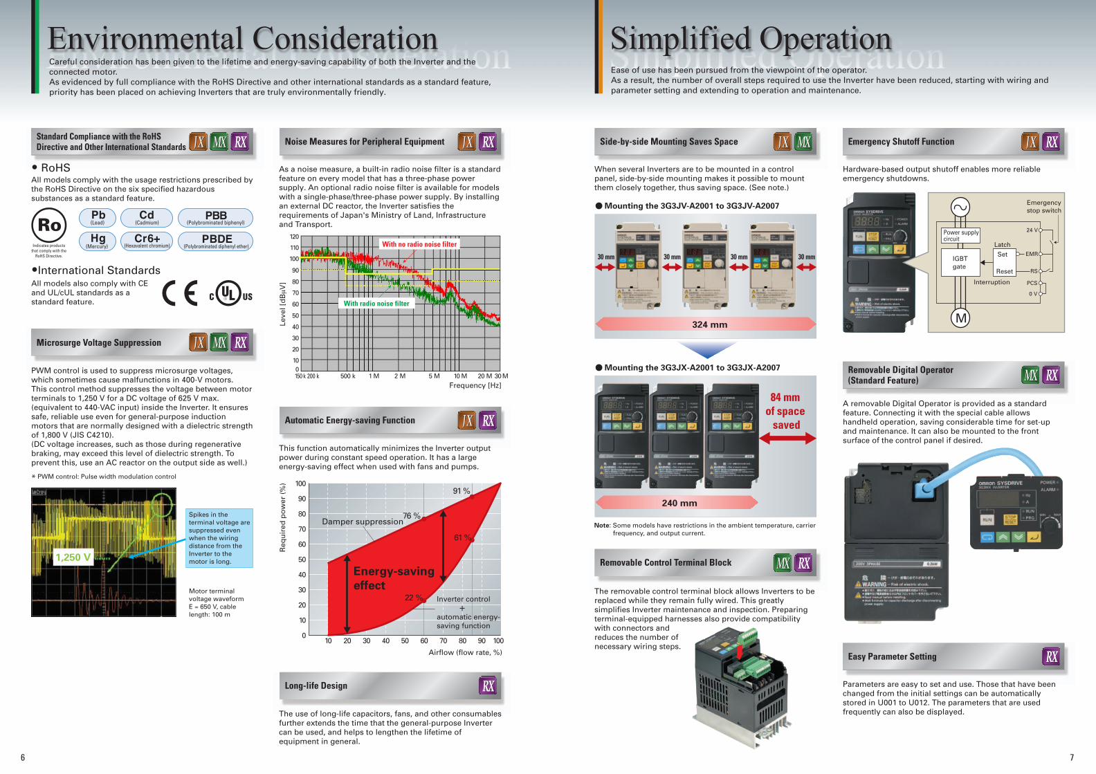
Note: Some models have restrictions in the ambient temperature, carrier frequency, and output current.
24 V
PCS
0 V
RS
Emergency stop switch
M
Environmental Consideration Simplified OperationCareful consideration has been given to the lifetime and energy-saving capability of both the Inverter and theconnected motor. As evidenced by full compliance with the RoHS Directive and other international standards as a standard feature, priority has been placed on achieving Inverters that are truly environmentally friendly.
Ease of use has been pursued from the viewpoint of the operator. As a result, the number of overall steps required to use the Inverter have been reduced, starting with wiring and parameter setting and extending to operation and maintenance.
All models comply with the usage restrictions prescribed by the RoHS Directive on the six specified hazardous substances as a standard feature.
PWM control is used to suppress microsurge voltages, which sometimes cause malfunctions in 400-V motors. This control method suppresses the voltage between motor terminals to 1,250 V for a DC voltage of 625 V max. (equivalent to 440-VAC input) inside the Inverter. It ensures safe, reliable use even for general-purpose induction motors that are normally designed with a dielectric strength of 1,800 V (JIS C4210).(DC voltage increases, such as those during regenerative braking, may exceed this level of dielectric strength. To prevent this, use an AC reactor on the output side as well.)
As a noise measure, a built-in radio noise filter is a standard feature on every model that has a three-phase power supply. An optional radio noise filter is available for models with a single-phase/three-phase power supply. By installing an external DC reactor, the Inverter satisfies the requirements of Japan's Ministry of Land, Infrastructure and Transport.
When several Inverters are to be mounted in a control panel, side-by-side mounting makes it possible to mount them closely together, thus saving space. (See note.)
Hardware-based output shutoff enables more reliable emergency shutdowns.
A removable Digital Operator is provided as a standard feature. Connecting it with the special cable allows handheld operation, saving considerable time for set-up and maintenance. It can also be mounted to the front surface of the control panel if desired.
Parameters are easy to set and use. Those that have beenchanged from the initial settings can be automaticallystored in U001 to U012. The parameters that are used frequently can also be displayed.
The removable control terminal block allows Inverters to be replaced while they remain fully wired. This greatly simplifies Inverter maintenance and inspection. Preparing terminal-equipped harnesses also provide compatibility with connectors and reduces the number of necessary wiring steps.
This function automatically minimizes the Inverter output power during constant speed operation. It has a large energy-saving effect when used with fans and pumps.
The use of long-life capacitors, fans, and other consumables further extends the time that the general-purpose Inverter can be used, and helps to lengthen the lifetime of equipment in general.
All models also comply with CE and UL/cUL standards as a standard feature.
Indicates products that comply with the
RoHS Directive.
(Lead)
(Mercury)
(Cadmium)
(Hexavalent chromium)
(Polybrominated biphenyl)
(Polybrominated diphenyl ether)
* PWM control: Pulse width modulation control
Spikes in the terminal voltage are suppressed even when the wiring distance from the Inverter to the motor is long.
Motor terminal voltage waveformE = 650 V, cable length: 100 m
Req
uir
ed p
ow
er (
%)
120
110
100
90
80
70
60
50
40
30
20
100150 k 200 k 500 k 1 M 2 M 5 M 10 M 20 M 30M
With radio noise filter
With no radio noise filter
Leve
l [d
Bµ
V]
Frequency [Hz]
Inverter control + automatic energy-saving function
Airflow (flow rate, %)
Mounting the 3G3JV-A2001 to 3G3JV-A2007
Mounting the 3G3JX-A2001 to 3G3JX-A2007
Simple Positioning Control with the Inverter PID Control Stall Prevention
Momentary Power Interruption Restart
8
Previously...Functions
Using the JX, MX, RX...
With Overcurrent Suppression Disabled
With Overcurrent Suppression Enabled
Example of Interrupt Feeding
h
Sensor position
Sensor
Speed
Feeding amount
Sensor input
Stopping point
Pump room
M M
PID
200 %
100 %
600 1200
Rotation Speed (min-1)
[Example of Speed vs. Torque Characteristics]
1800
9
In the SYSDRIVE MX Series...
In the SYSDRIVE RX Series...
Sensorless vector controlSensorless vector control in 0-Hz domainVector control with a PG
Sensorless Vector Control in
0-Hz DomainMEMOMEMO Power supply
Inverter output
Motor rotation
Power supply
Inverter output
Motor rotation
Coasting
Coasting
t0 t2t1
t0t1
Example Timing Charts
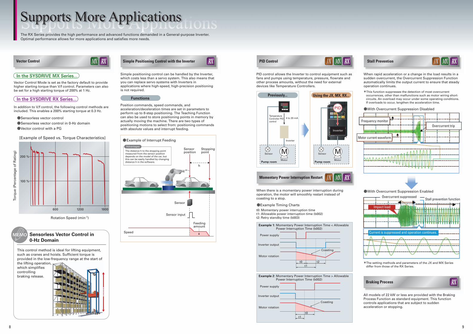
Supports More ApplicationsThe RX Series provides the high performance and advanced functions demanded in a General-purpose Inverter. Optimal performance allows for more applications and satisfies more needs.
Vector Control
Vector Control Mode is set as the factory default to provide higher starting torque than V/f control. Parameters can also be set for a high starting torque of 200% at 1 Hz.
Simple positioning control can be handled by the Inverter, which costs less than a servo system. This also means that you can replace servo systems with Inverters in applications where high-speed, high-precision positioning is not required.
PID control allows the Inverter to control equipment such as fans and pumps using temperature, pressure, flowrate and other process amounts, without the need for external devices like Temperature Controllers.
When rapid acceleration or a change in the load results in a sudden overcurrent, the Overcurrent Suppression Function automatically limits the output current to ensure that steady operation continues.
*This function suppresses the detection of most overcurrent occurrences, other than malfunctions such as motor wiring short- circuits. An overload may occur under some operating conditions. If overloads to occur, lengthen the acceleration time.
*The setting methods and parameters of the JX and MX Series differ from those of the RX Series.
When there is a momentary power interruption during operation, the motor will smoothly restart instead of coasting to a stop.
Position commands, speed commands, and acceleration/deceleration times are set in parameters to perform up to 8-step positioning. The Teaching Function can also be used to store positioning points in memory by actually moving the machine. There are two types of positioning motions to select from: positioning commands with absolute values and interrupt feeding.
In addition to V/f control, the following control methods are included. This enables a 200% starting torque at 0.3 Hz.
Torq
ue
(Per
cen
tag
e o
f R
atin
g)
This control method is ideal for lifting equipment, such as cranes and hoists. Sufficient torque is provided in the low-frequency range at the start of the lifting operation, which simplifies controlling braking release.
Temperature Controller PID control
4 to 20 mA
Inverter
Inverter
Sensor
MotorPump room
Sensor
Motor
t0: Momentary power interruption timet1: Allowable power interruption time (b002)t2: Retry standby time (b003)
Example 1: Momentary Power Interruption Time < Allowable Power Interruption Time (b002)
Example 2: Momentary Power Interruption Time > Allowable Power Interruption Time (b002)
Motor current waveform
Overcurrent tripFrequency monitor
Overcurrent suppressedStall prevention function
Impact load
Current is suppressed and operation continues.
Braking Process
All models of 22 kW or less are provided with the Braking Process Function as standard equipment. This function controls applications that are subject to sudden acceleration or stopping.
The distance h to the stopping point measured from the sensor position depends on the model of the car, but this can be easily handled by changing distance h in the software.
Advantages

10
Simple, Compact Inverters
SYSDRIVE JX Series
Nomenclature and Functions
■ Inverter Nomenclature and Functions
Note 1. Connect the communications cable after opening the cover of the communications connector. Remove the front cover to switch communications. 2. The cover of the communications connector is removable. Remove the front cover to attach it.
8k8k8k8
Bottom cover
Remove this cover when wiring the lower terminal blocks.
Remove this cover when wiring the upper
terminal block.
Used to set parameters, perform various
monitoring, and start and stop the Inverter.
Displays relevant data, such as frequency reference, output current, and set values.
Top Cover
Digital Operator
Data Display
Remove this cover when wiring the upper or lower
terminal block.
Front cover
Sets the frequency reference within a range between 0 Hz and the maximum frequency.
Frequency adjuster
Communications connector (with cover)
Selection
Features
SY
SD
RIV
EJX
Series
SY
SD
RIV
EM
X S
eriesS
YS
DR
IVE
RX
Series
SY
SD
RIV
EO
ption
Overview
ofInverter S
election
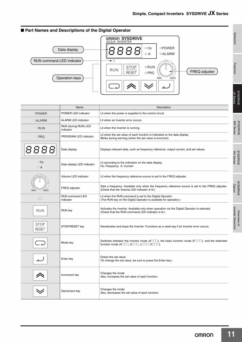
Simple, Compact Inverters SYSDRIVE JX Series
■ Part Names and Descriptions of the Digital Operator
Name Description
POWER LED indicator Lit when the power is supplied to the control circuit.
ALARM LED indicator Lit when an Inverter error occurs.
RUN (during RUN) LED indicator
Lit when the Inverter is running.
PROGRAM LED indicatorLit when the set value of each function is indicated on the data display.Blinks during warning (when the set value is incorrect).
Data display Displays relevant data, such as frequency reference, output current, and set values.
Data display LED indicatorLit according to the indication on the data display.Hz: Frequency A: Current
Volume LED indicator Lit when the frequency reference source is set to the FREQ adjuster.
FREQ adjusterSets a frequency. Available only when the frequency reference source is set to the FREQ adjuster.(Check that the Volume LED indicator is lit.)
RUN command LED indicator
Lit when the RUN command is set to the Digital Operator.(The RUN key on the Digital Operator is available for operation.)
RUN keyActivates the Inverter. Available only when operation via the Digital Operator is selected.(Check that the RUN command LED indicator is lit.)
STOP/RESET key Decelerates and stops the Inverter. Functions as a reset key if an Inverter error occurs.
Mode keySwitches between the monitor mode (d@@@), the basic function mode (F@@@), and the extendedfunction mode (A@@@, b@@@, c@@@, H@@@).
Enter keyEnters the set value.(To change the set value, be sure to press the Enter key.)
Increment keyChanges the mode.Also, increases the set value of each function.
Decrement keyChanges the mode.Also, decreases the set value of each function.
8k8k8k8Data display
RUN command LED indicator
FREQ adjuster
Operation keys
8k8k8k8
11
1
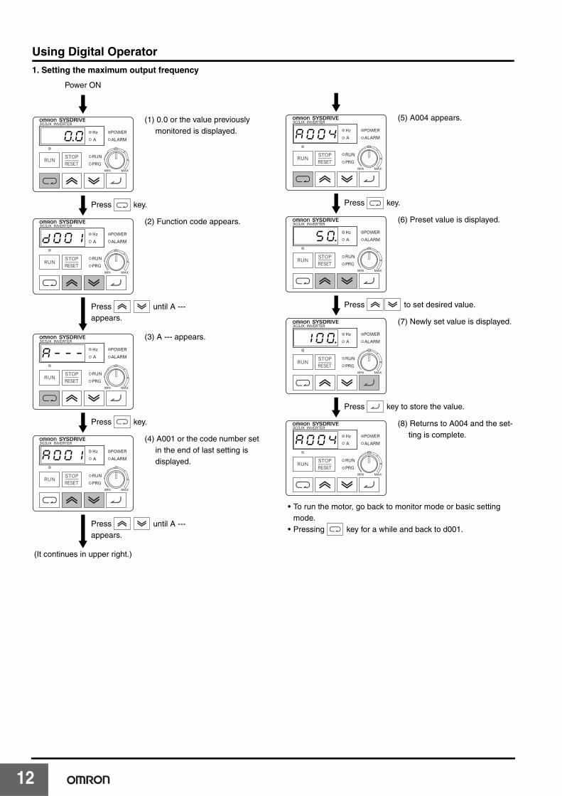
Using Digital Operator1. Setting the maximum output frequency
Power ON
(1) 0.0 or the value previously monitored is displayed.
(2) Function code appears.
(3) A --- appears.
(4) A001 or the code number set in the end of last setting is displayed.
(It continues in upper right.)
0.0
Press key.
Ddk0k0k1
Press until A --- appears.
ak-k-k-
Press key.
ak0k0k1
Press until A --- appears.
(5) A004 appears.
(6) Preset value is displayed.
(7) Newly set value is displayed.
(8) Returns to A004 and the set-ting is complete.
• To run the motor, go back to monitor mode or basic setting mode.
• Pressing key for a while and back to d001.
ak0k0k4
Press key.
5k0.
Press to set desired value.
1k0k0.
Press key to store the value.
ak0k0k4
2
Selection
Features
SY
SD
RIV
EJX
Series
SY
SD
RIV
EM
X S
eriesS
YS
DR
IVE
RX
Series
SY
SD
RIV
EO
ption
Overview
ofInverter S
election
Simple, Compact Inverters SYSDRIVE JX Series
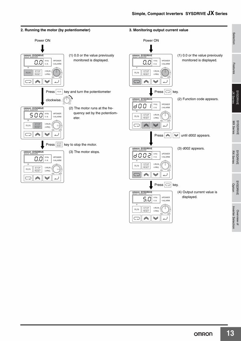
2. Running the motor (by potentiometer) 3. Monitoring output current value
Power ON
(1) 0.0 or the value previously monitored is displayed.
(2) The motor runs at the fre-quency set by the potentiom-eter.
(3) The motor stops.
0.0
Press key and turn the potentiometer
clockwise.
D5k0k0
Press key to stop the motor.
0.0
Power ON
(1) 0.0 or the value previously monitored is displayed.
(2) Function code appears.
(3) d002 appears.
(4) Output current value is displayed.
0.0
Press key.
Ddk0k0k1
Press until d002 appears.
Ddk0k0k2
Press key.
5.0
13
1
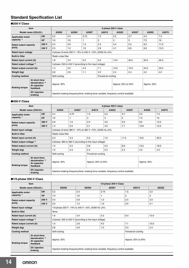
Standard Specification List●200-V Class
●400-V Class
●1/3-phase 200-V Class
Item 3-phase 200-V class
Model name (3G3JX-) A2002 A2004 A2007 A2015 A2022 A2037 A2055 A2075
Applicable motor capacity *1
kW 0.2 0.4 0.75 1.5 2.2 3.7 5.5 7.5
HP 1/4 1/2 1 2 3 5 7.5 10
Rated output capacity (kVA)
200 V 0.4 0.9 1.3 2.4 3.4 5.5 8.3 11.0
240 V 0.5 1.0 1.6 2.9 4.1 6.6 9.9 13.3
Rated input voltage 3-phase (3-wire) 200 V −15% to 240 V +10%, 50/60 Hz ±5%
Built-in filter Radio noise filter
Rated input current (A) 1.8 3.4 5.2 9.3 13.0 20.0 30.0 40.0
Rated output voltage *2 3-phase: 200 to 240 V (according to the input voltage)
Rated output current (A) 1.4 2.6 4.0 7.1 10.0 15.9 24.0 32.0
Weight (kg) 0.8 0.9 1.1 2.2 2.4 2.4 4.2 4.2
Cooling method Self-cooling Forced-air-cooling
Braking torque
At short-time deceleration *3At capacitor feedback
Approx. 50% Approx. 20% to 40% Approx. 20%
DC injection braking
Injection braking frequency/time, braking force variable, frequency control available
Item 3-phase 400-V class
Model name (3G3JX-) A4004 A4007 A4015 A4022 A4037 A4055 A4075
Applicable motor capacity *1
kW 0.4 0.75 1.5 2.2 3.7 5.5 7.5
HP 1/2 1 2 3 5 7.5 10
Rated output capacity (kVA)
380 V 0.9 1.6 2.5 3.6 5.6 8.5 10.5
480 V 1.2 2.0 3.1 4.5 7.1 10.8 13.3
Rated input voltage 3-phase (3-wire) 380 V −15% to 480 V +10%, 50/60 Hz ±5%
Built-in filter Radio noise filter
Rated input current (A) 2.0 3.3 5.0 7.0 11.0 16.5 20.0
Rated output voltage *2 3-phase: 380 to 480 V (according to the input voltage)
Rated output current (A) 1.5 2.5 3.8 5.5 8.6 13.0 16.0
Weight (kg) 1.5 2.3 2.4 2.4 2.4 4.2 4.2
Cooling method Self-cooling Forced-air-cooling
Braking torque
At short-time deceleration *3At capacitor feedback
Approx. 50% Approx. 20% to 40% Approx. 20%
DC injection braking
Injection braking frequency/time, braking force variable, frequency control available
Item 1/3-phase 200-V Class
Model name (3G3JX-) AE002 AE004 AE007 AE015 AE022
Applicable motor capacity *1
kW 0.2 0.4 0.75 1.5 2.2
HP 1/4 1/2 1 2 3
Rated output capacity (kVA)
200 V 0.4 0.9 1.3 2.4 3.4
240 V 0.5 1.0 1.6 2.9 4.1
Rated input voltage 1/3-phase 200 V −15% to 240 V +10%, 50/60 Hz ±5%
Built-in filter None
Rated input current (A) 1.8 3.4 5.2 9.3 13.0
Rated output voltage *2 3-phase: 200 to 240 V (according to the input voltage)
Rated output current (A) 1.4 2.6 4.0 7.1 10.0
Weight (kg) 0.8 0.9 1.5 2.3 2.4
Cooling method Self-cooling Forced-air-cooling
Braking torque
At short-time deceleration *3At capacitor feedback
Approx. 50% Approx. 20% to 40%
DC injection braking
Injection braking frequency/time, braking force variable, frequency control available
4
Selection
Features
SY
SD
RIV
EJX
Series
SY
SD
RIV
EM
X S
eriesS
YS
DR
IVE
RX
Series
SY
SD
RIV
EO
ption
Overview
ofInverter S
election
Simple, Compact Inverters SYSDRIVE JX Series
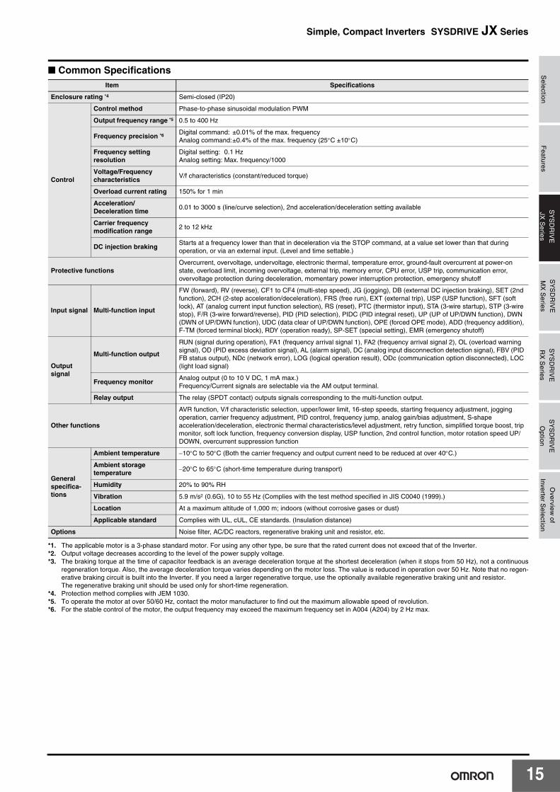
■ Common Specifications
*1. The applicable motor is a 3-phase standard motor. For using any other type, be sure that the rated current does not exceed that of the Inverter.*2. Output voltage decreases according to the level of the power supply voltage.*3. The braking torque at the time of capacitor feedback is an average deceleration torque at the shortest deceleration (when it stops from 50 Hz), not a continuous
regeneration torque. Also, the average deceleration torque varies depending on the motor loss. The value is reduced in operation over 50 Hz. Note that no regen-erative braking circuit is built into the Inverter. If you need a larger regenerative torque, use the optionally available regenerative braking unit and resistor. The regenerative braking unit should be used only for short-time regeneration.
*4. Protection method complies with JEM 1030. *5. To operate the motor at over 50/60 Hz, contact the motor manufacturer to find out the maximum allowable speed of revolution.*6. For the stable control of the motor, the output frequency may exceed the maximum frequency set in A004 (A204) by 2 Hz max.
Item Specifications
Enclosure rating *4 Semi-closed (IP20)
Control
Control method Phase-to-phase sinusoidal modulation PWM
Output frequency range *5 0.5 to 400 Hz
Frequency precision *6Digital command: ±0.01% of the max. frequencyAnalog command:±0.4% of the max. frequency (25°C ±10°C)
Frequency setting resolution
Digital setting: 0.1 HzAnalog setting: Max. frequency/1000
Voltage/Frequency characteristics
V/f characteristics (constant/reduced torque)
Overload current rating 150% for 1 min
Acceleration/Deceleration time
0.01 to 3000 s (line/curve selection), 2nd acceleration/deceleration setting available
Carrier frequency modification range
2 to 12 kHz
DC injection brakingStarts at a frequency lower than that in deceleration via the STOP command, at a value set lower than that during operation, or via an external input. (Level and time settable.)
Protective functionsOvercurrent, overvoltage, undervoltage, electronic thermal, temperature error, ground-fault overcurrent at power-on state, overload limit, incoming overvoltage, external trip, memory error, CPU error, USP trip, communication error, overvoltage protection during deceleration, momentary power interruption protection, emergency shutoff
Input signal Multi-function input
FW (forward), RV (reverse), CF1 to CF4 (multi-step speed), JG (jogging), DB (external DC injection braking), SET (2nd function), 2CH (2-step acceleration/deceleration), FRS (free run), EXT (external trip), USP (USP function), SFT (soft lock), AT (analog current input function selection), RS (reset), PTC (thermistor input), STA (3-wire startup), STP (3-wire stop), F/R (3-wire forward/reverse), PID (PID selection), PIDC (PID integral reset), UP (UP of UP/DWN function), DWN (DWN of UP/DWN function), UDC (data clear of UP/DWN function), OPE (forced OPE mode), ADD (frequency addition), F-TM (forced terminal block), RDY (operation ready), SP-SET (special setting), EMR (emergency shutoff)
Output signal
Multi-function output
RUN (signal during operation), FA1 (frequency arrival signal 1), FA2 (frequency arrival signal 2), OL (overload warning signal), OD (PID excess deviation signal), AL (alarm signal), DC (analog input disconnection detection signal), FBV (PID FB status output), NDc (network error), LOG (logical operation result), ODc (communication option disconnected), LOC (light load signal)
Frequency monitorAnalog output (0 to 10 V DC, 1 mA max.)Frequency/Current signals are selectable via the AM output terminal.
Relay output The relay (SPDT contact) outputs signals corresponding to the multi-function output.
Other functions
AVR function, V/f characteristic selection, upper/lower limit, 16-step speeds, starting frequency adjustment, jogging operation, carrier frequency adjustment, PID control, frequency jump, analog gain/bias adjustment, S-shape acceleration/deceleration, electronic thermal characteristics/level adjustment, retry function, simplified torque boost, trip monitor, soft lock function, frequency conversion display, USP function, 2nd control function, motor rotation speed UP/DOWN, overcurrent suppression function
General specifica-tions
Ambient temperature −10°C to 50°C (Both the carrier frequency and output current need to be reduced at over 40°C.)
Ambient storage temperature
−20°C to 65°C (short-time temperature during transport)
Humidity 20% to 90% RH
Vibration 5.9 m/s2 (0.6G), 10 to 55 Hz (Complies with the test method specified in JIS C0040 (1999).)
Location At a maximum altitude of 1,000 m; indoors (without corrosive gases or dust)
Applicable standard Complies with UL, cUL, CE standards. (Insulation distance)
Options Noise filter, AC/DC reactors, regenerative braking unit and resistor, etc.
15
1
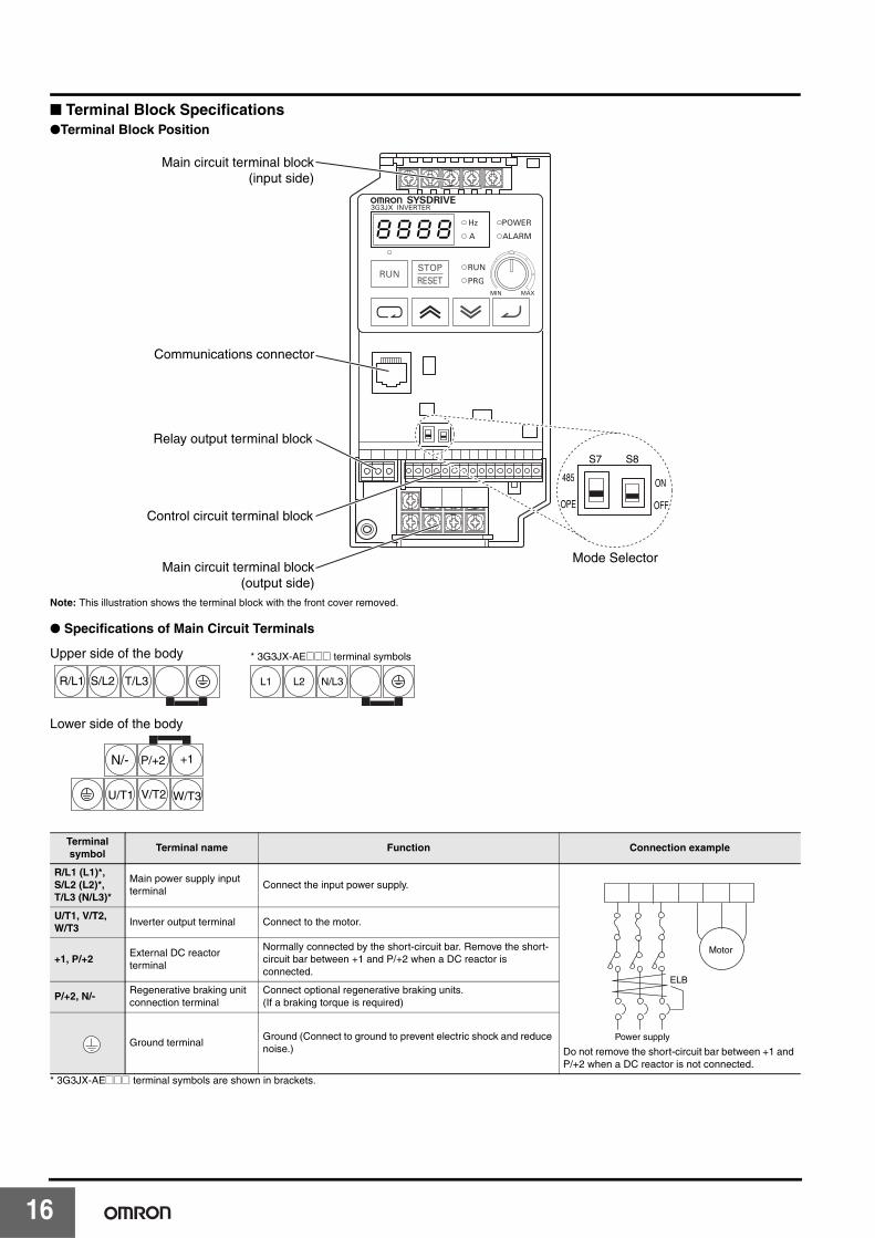
■ Terminal Block Specifications●Terminal Block Position
Note: This illustration shows the terminal block with the front cover removed.
● Specifications of Main Circuit Terminals
* 3G3JX-AE@@@ terminal symbols are shown in brackets.
Terminal symbol
Terminal name Function Connection example
R/L1 (L1)*, S/L2 (L2)*, T/L3 (N/L3)*
Main power supply input terminal
Connect the input power supply.
Do not remove the short-circuit bar between +1 and P/+2 when a DC reactor is not connected.
U/T1, V/T2, W/T3
Inverter output terminal Connect to the motor.
+1, P/+2External DC reactor terminal
Normally connected by the short-circuit bar. Remove the short-circuit bar between +1 and P/+2 when a DC reactor is connected.
P/+2, N/-Regenerative braking unit connection terminal
Connect optional regenerative braking units.(If a braking torque is required)
Ground terminalGround (Connect to ground to prevent electric shock and reduce noise.)
8k8k8k8
S7 S8
485
OPE
ON
OFF
Main circuit terminal block (input side)
Communications connector
Relay output terminal block
Control circuit terminal block
Main circuit terminal block (output side)
Mode Selector
T/L3 L1 L2 N/L3
Upper side of the body
Lower side of the body
* 3G3JX-AE@@@ terminal symbols
R/L1 S/L2
N/- P/+2 +1
U/T1 V/T2 W/T3
Power supply
ELB
Motor
6
Selection
Features
SY
SD
RIV
EJX
Series
SY
SD
RIV
EM
X S
eriesS
YS
DR
IVE
RX
Series
SY
SD
RIV
EO
ption
Overview
ofInverter S
election
Simple, Compact Inverters SYSDRIVE JX Series
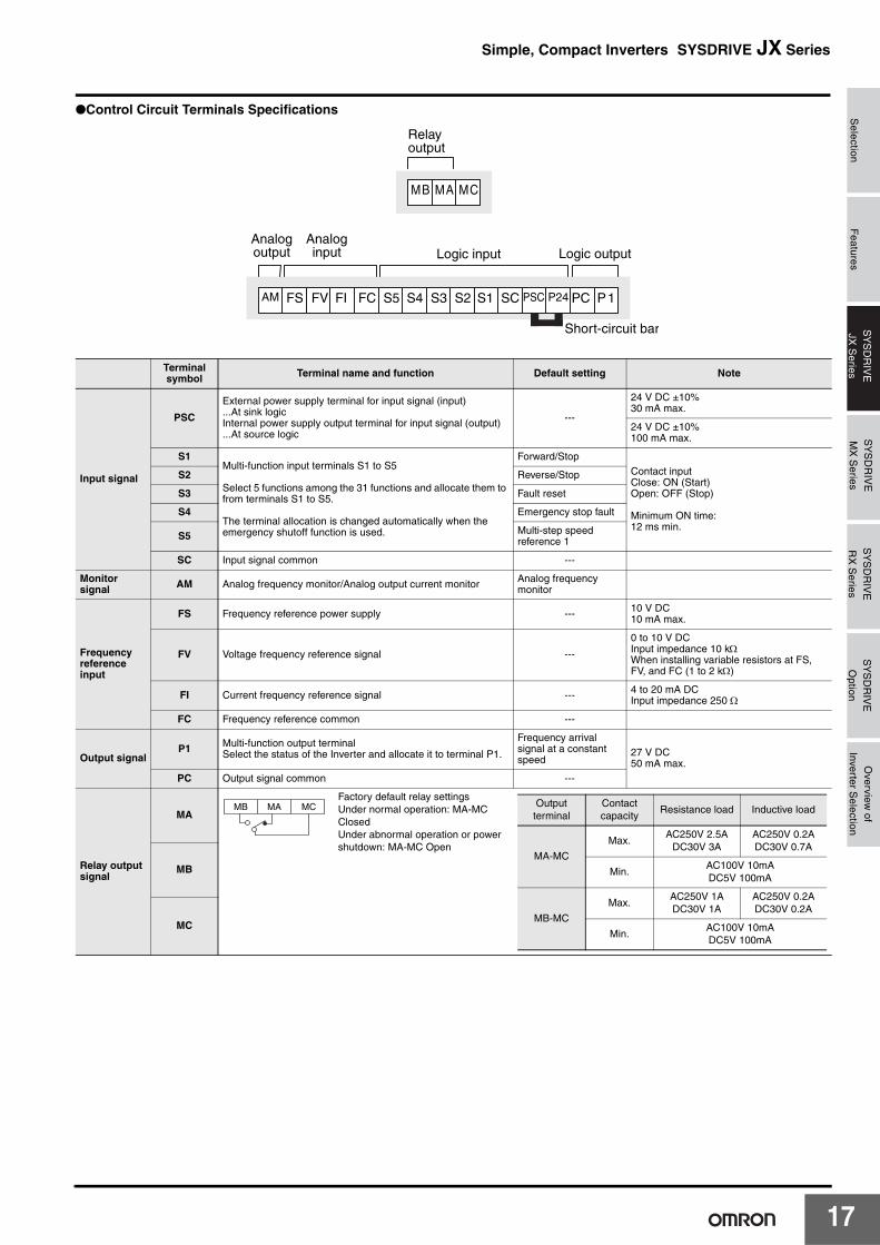
●Control Circuit Terminals Specifications
Terminal symbol Terminal name and function Default setting Note
Input signal
PSC
External power supply terminal for input signal (input)...At sink logicInternal power supply output terminal for input signal (output)...At source logic
---
24 V DC ±10%30 mA max.
24 V DC ±10%100 mA max.
S1Multi-function input terminals S1 to S5
Select 5 functions among the 31 functions and allocate them to from terminals S1 to S5.
The terminal allocation is changed automatically when the emergency shutoff function is used.
Forward/StopContact inputClose: ON (Start)Open: OFF (Stop)
Minimum ON time:12 ms min.
S2 Reverse/Stop
S3 Fault reset
S4 Emergency stop fault
S5 Multi-step speed reference 1
SC Input signal common ---
Monitor signal AM Analog frequency monitor/Analog output current monitor Analog frequency
monitor
Frequency reference input
FS Frequency reference power supply --- 10 V DC10 mA max.
FV Voltage frequency reference signal ---
0 to 10 V DCInput impedance 10 kΩWhen installing variable resistors at FS, FV, and FC (1 to 2 kΩ)
FI Current frequency reference signal --- 4 to 20 mA DCInput impedance 250 Ω
FC Frequency reference common ---
Output signalP1 Multi-function output terminal
Select the status of the Inverter and allocate it to terminal P1.
Frequency arrival signal at a constant speed
27 V DC50 mA max.
PC Output signal common ---
Relay output signal
MA
Factory default relay settingsUnder normal operation: MA-MC ClosedUnder abnormal operation or power shutdown: MA-MC Open
MB
MC
MB MA MC
Relayoutput
AM FS FV FI FC S5 S4 S3 S2 S1 SC PSC P24 PC P1
Analogoutput Logic input Logic output
Short-circuit bar
Analoginput
MB MA MC Output terminal
Contact capacity
Resistance load Inductive load
MA-MC
Max.AC250V 2.5A
DC30V 3AAC250V 0.2ADC30V 0.7A
Min.AC100V 10mADC5V 100mA
MB-MC
Max.AC250V 1ADC30V 1A
AC250V 0.2ADC30V 0.2A
Min.AC100V 10mADC5V 100mA
17

1
●Mode Selector
RS-485 Communication/Operator Selector (S7)Select the mode according to the option connected to the communications connector.
When using the 3G3AX-OP01 supplied with the Inverter, it is available regardless of the switch condition.
Emergency shutoff selector (S8)Use this selector to enable the emergency shutoff input function.
* The multi-function input terminal 3 is switched to a terminal for emergency shutoff input, and the allocation of other multi-function input terminals is also changedautomatically. Do not set to ON immoderately. For details, refer to "Emergency Shutoff Input Function".
Symbol Name Status Description
S7RS-485 communication/operator selector
485 RS485 Modbus communication
OPE [Default] Digital Operator (Option: 3G3AX-OP1)
Symbol Name Status Description
S8Emergency shutoff selector
ON Emergency shutoff input enabled *
OFF[Default]
Normal
8
Selection
Features
SY
SD
RIV
EJX
Series
SY
SD
RIV
EM
X S
eriesS
YS
DR
IVE
RX
Series
SY
SD
RIV
EO
ption
Overview
ofInverter S
election
Simple, Compact Inverters SYSDRIVE JX Series
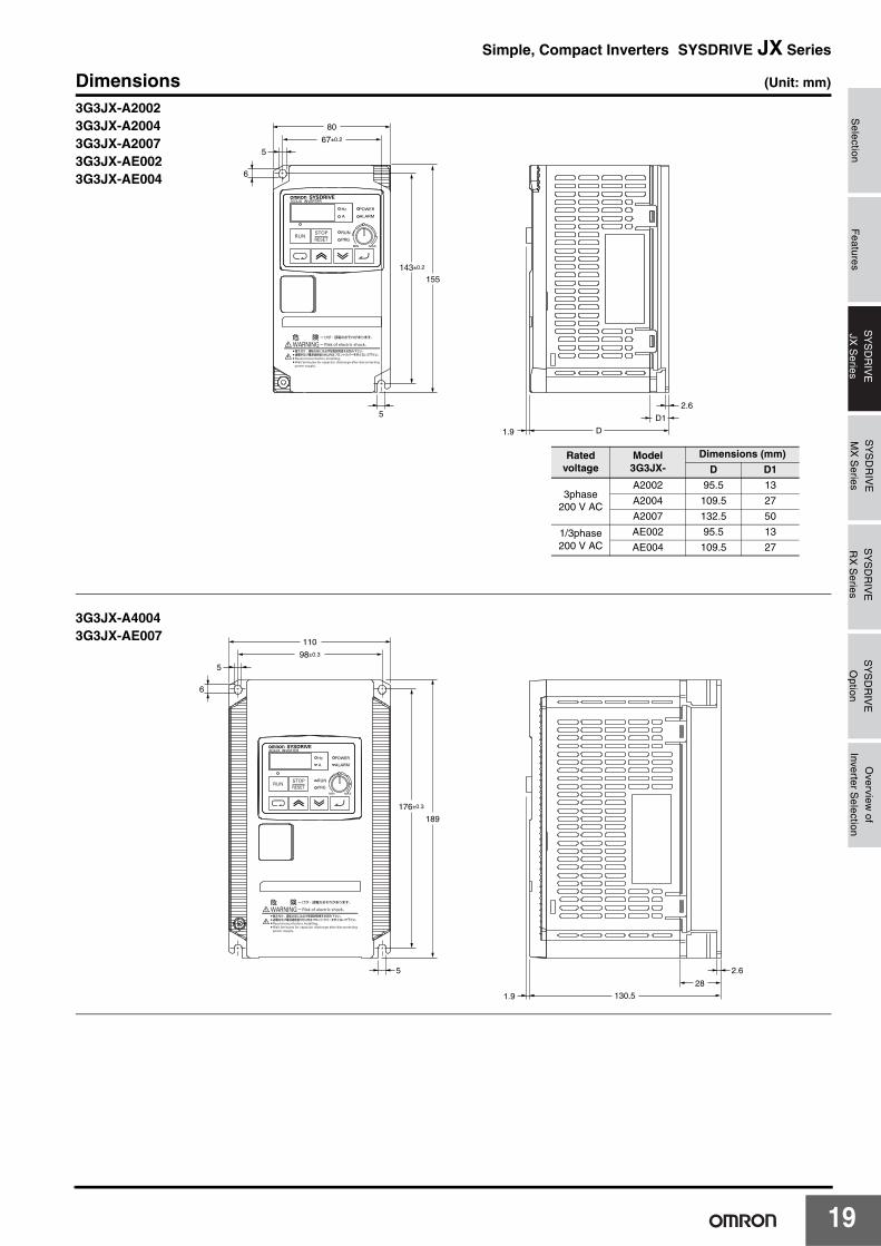
Dimensions (Unit: mm)
143±0.2
5
155
67±0.2
80
5
6
2.6
D1
D1.9
3G3JX-A20023G3JX-A20043G3JX-A20073G3JX-AE0023G3JX-AE004
Rated voltage
Model3G3JX-
Dimensions (mm)
D D1
3phase200 V AC
A2002 95.5 13
A2004 109.5 27
A2007 132.5 50
1/3phase200 V AC
AE002 95.5 13
AE004 109.5 27
6
5
5
110
176±0.3
98±0.3
189
28
2.6
1.9 130.5
3G3JX-A40043G3JX-AE007
19

2
6
5
5
110
176±0.3
98±0.3
189
6
55
1.9 157.5
3G3JX-A20153G3JX-A20223G3JX-A20373G3JX-A40073G3JX-A40153G3JX-A40223G3JX-A40373G3JX-AE0153G3JX-AE022
180
164
250
167.5
77.5
235
6 1.9
3G3JX-A20553G3JX-A20753G3JX-A40553G3JX-A4075
0

Selection
Features
SY
SD
RIV
EJX
Series
SY
SD
RIV
EM
X S
eriesS
YS
DR
IVE
RX
Series
SY
SD
RIV
EO
ption
Overview
ofInverter S
election
Simple, Compact Inverters SYSDRIVE JX Series
Standard Connection Diagram
Braking unitDC reactor (optional)
3-phase 200 V AC1/3-phase 200 V AC *23-phase 400 V AC
Multi-function input 1
Multi-function input 2
Multi-function input 3
Multi-function input 4
Multi-function input 5
Frequency reference power supply
Frequency reference (1 to 2 kΩ)
Frequency reference input (voltage)
Frequency reference input (current)
*1. The 3G3JX-AE@@@ terminal symbols are shown in brackets.*2. Connect a single-phase 200-V AC input to terminals L1 and N/L3.*3. By factory default, MA is set to MC contact, and MB to NO contact in the relay output (MA, MB) selection (C036).
Frequency reference common
Sequence input common
M
R/L1 (L1)*1+1 P/+2 N/-
T/L3 (N/L3)*1
S/L2 (L2)*1
U/L1
W/T3
P1
PC
Multi-function output
Multi-function output common
AM Analog monitor output
Relay output *3
Common
V/T2
PSC
P24
S2
S1
S5
SC
FS
FI
FC
FV
S4
S3
MB
MA
MC
21
2
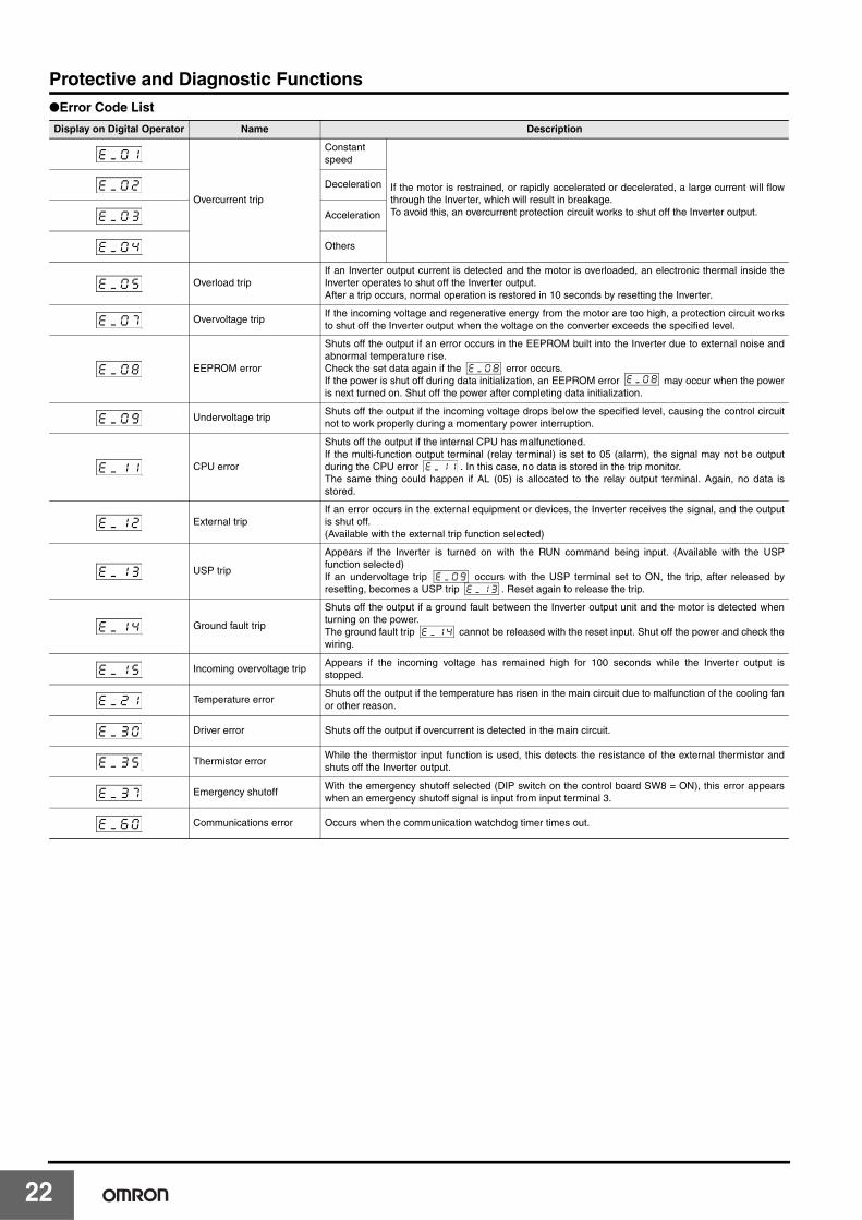
Protective and Diagnostic Functions●Error Code List
Display on Digital Operator Name Description
Overcurrent trip
Constantspeed
If the motor is restrained, or rapidly accelerated or decelerated, a large current will flowthrough the Inverter, which will result in breakage.To avoid this, an overcurrent protection circuit works to shut off the Inverter output.
Deceleration
Acceleration
Others
Overload tripIf an Inverter output current is detected and the motor is overloaded, an electronic thermal inside theInverter operates to shut off the Inverter output.After a trip occurs, normal operation is restored in 10 seconds by resetting the Inverter.
Overvoltage tripIf the incoming voltage and regenerative energy from the motor are too high, a protection circuit worksto shut off the Inverter output when the voltage on the converter exceeds the specified level.
EEPROM error
Shuts off the output if an error occurs in the EEPROM built into the Inverter due to external noise andabnormal temperature rise.Check the set data again if the error occurs.If the power is shut off during data initialization, an EEPROM error may occur when the poweris next turned on. Shut off the power after completing data initialization.
Undervoltage tripShuts off the output if the incoming voltage drops below the specified level, causing the control circuitnot to work properly during a momentary power interruption.
CPU error
Shuts off the output if the internal CPU has malfunctioned.If the multi-function output terminal (relay terminal) is set to 05 (alarm), the signal may not be outputduring the CPU error . In this case, no data is stored in the trip monitor.The same thing could happen if AL (05) is allocated to the relay output terminal. Again, no data isstored.
External tripIf an error occurs in the external equipment or devices, the Inverter receives the signal, and the outputis shut off.(Available with the external trip function selected)
USP trip
Appears if the Inverter is turned on with the RUN command being input. (Available with the USPfunction selected)If an undervoltage trip occurs with the USP terminal set to ON, the trip, after released byresetting, becomes a USP trip . Reset again to release the trip.
Ground fault trip
Shuts off the output if a ground fault between the Inverter output unit and the motor is detected whenturning on the power.The ground fault trip cannot be released with the reset input. Shut off the power and check thewiring.
Incoming overvoltage tripAppears if the incoming voltage has remained high for 100 seconds while the Inverter output isstopped.
Temperature errorShuts off the output if the temperature has risen in the main circuit due to malfunction of the cooling fanor other reason.
Driver error Shuts off the output if overcurrent is detected in the main circuit.
Thermistor errorWhile the thermistor input function is used, this detects the resistance of the external thermistor andshuts off the Inverter output.
Emergency shutoffWith the emergency shutoff selected (DIP switch on the control board SW8 = ON), this error appearswhen an emergency shutoff signal is input from input terminal 3.
Communications error Occurs when the communication watchdog timer times out.
ek_k0k1
ek_k0k2
ek_k0k3
ek_k0k4
ek_k0k5
ek_k0k7
ek_k0k8 ek_k0k8ek_k0k8
ek_k0k9
ek_k1k1 ek_k1k1
ek_k1k2
ek_k1k3 ek_k0k9ek_k1k3
ek_k1k4 ek_k1k4
ek_k1k5
ek_k2k1
ek_k3k0
ek_k3k5
ek_k3k7
ek_k6k0
2
Selection
Features
SY
SD
RIV
EJX
Series
SY
SD
RIV
EM
X S
eriesS
YS
DR
IVE
RX
Series
SY
SD
RIV
EO
ption
Overview
ofInverter S
election
Simple, Compact Inverters SYSDRIVE JX Series
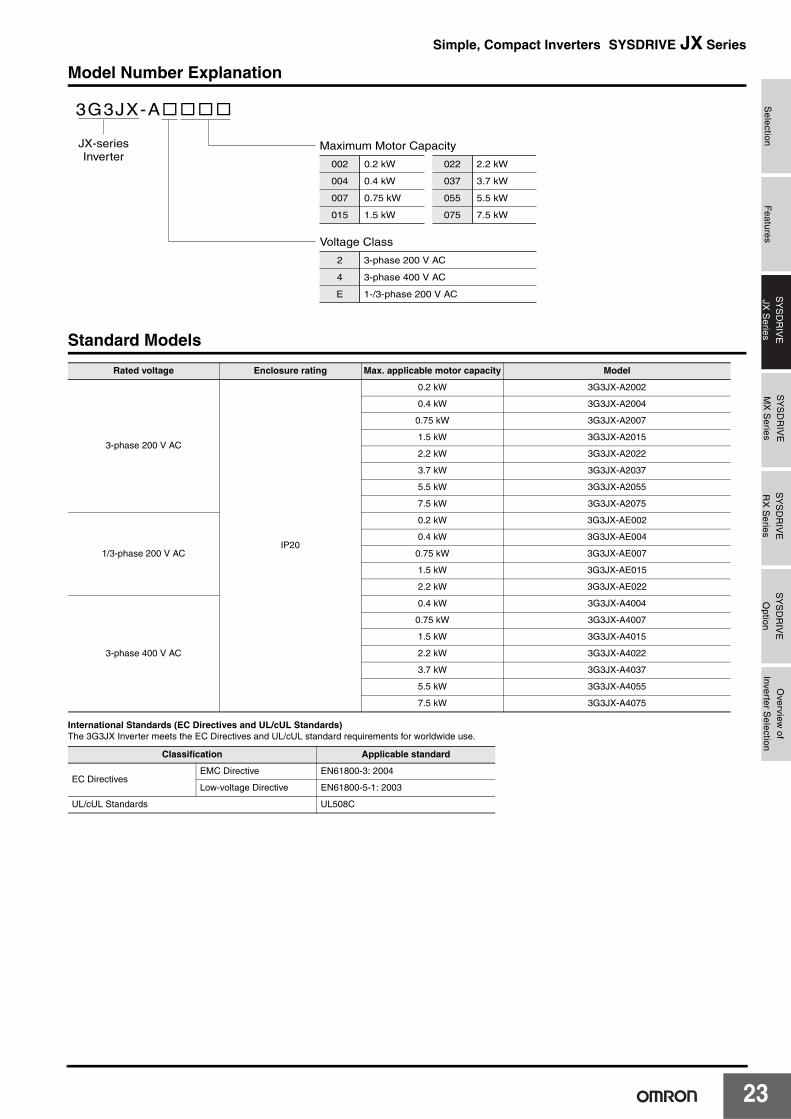
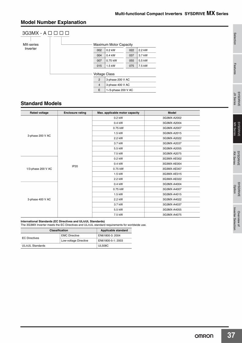
Model Number Explanation
Standard Models
International Standards (EC Directives and UL/cUL Standards)The 3G3JX Inverter meets the EC Directives and UL/cUL standard requirements for worldwide use.
Rated voltage Enclosure rating Max. applicable motor capacity Model
3-phase 200 V AC
IP20
0.2 kW 3G3JX-A2002
0.4 kW 3G3JX-A2004
0.75 kW 3G3JX-A2007
1.5 kW 3G3JX-A2015
2.2 kW 3G3JX-A2022
3.7 kW 3G3JX-A2037
5.5 kW 3G3JX-A2055
7.5 kW 3G3JX-A2075
1/3-phase 200 V AC
0.2 kW 3G3JX-AE002
0.4 kW 3G3JX-AE004
0.75 kW 3G3JX-AE007
1.5 kW 3G3JX-AE015
2.2 kW 3G3JX-AE022
3-phase 400 V AC
0.4 kW 3G3JX-A4004
0.75 kW 3G3JX-A4007
1.5 kW 3G3JX-A4015
2.2 kW 3G3JX-A4022
3.7 kW 3G3JX-A4037
5.5 kW 3G3JX-A4055
7.5 kW 3G3JX-A4075
Classification Applicable standard
EC DirectivesEMC Directive EN61800-3: 2004
Low-voltage Directive EN61800-5-1: 2003
UL/cUL Standards UL508C
3G3JX-A����
Maximum Motor Capacity
Voltage Class
JX-seriesInverter
002
004
007
0.2 kW
0.4 kW
0.75 kW
022
037
2.2 kW
3.7 kW
015 1.5 kW 075 7.5 kW
055 5.5 kW
2
4
3-phase 200 V AC
3-phase 400 V AC
E 1-/3-phase 200 V AC
23
24
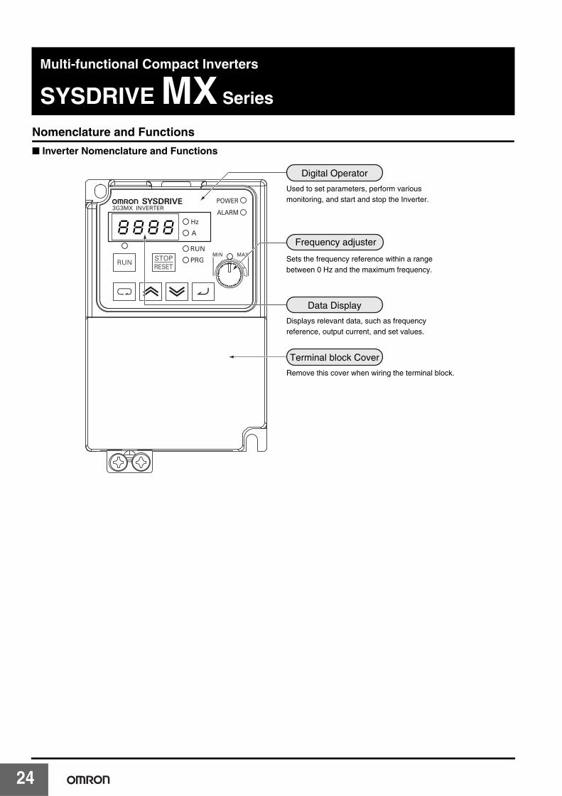
Multi-functional Compact Inverters
SYSDRIVE MX Series
Nomenclature and Functions
■ Inverter Nomenclature and Functions
8k8k8k8
Used to set parameters, perform various monitoring, and start and stop the Inverter.
Digital Operator
Sets the frequency reference within a range between 0 Hz and the maximum frequency.
Displays relevant data, such as frequency reference, output current, and set values.
Data Display
Remove this cover when wiring the terminal block.
Terminal block Cover
Frequency adjuster
Selection
Features
SY
SD
RIV
EM
X S
eriesS
YS
DR
IVE
RX
Series
SY
SD
RIV
EO
ptionO
verview of
Inverter Selection
SY
SD
RIV
EJX
Series
Multi-functional Compact Inverters SYSDRIVE MX Series
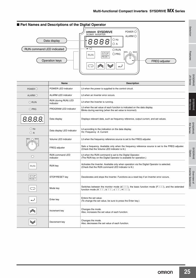
■ Part Names and Descriptions of the Digital Operator
Name Description
POWER LED indicator Lit when the power is supplied to the control circuit.
ALARM LED indicator Lit when an Inverter error occurs.
RUN (during RUN) LED indicator
Lit when the Inverter is running.
PROGRAM LED indicatorLit when the set value of each function is indicated on the data display.Blinks during warning (when the set value is incorrect).
Data display Displays relevant data, such as frequency reference, output current, and set values.
Data display LED indicatorLit according to the indication on the data display.Hz: Frequency A: Current
Volume LED indicator Lit when the frequency reference source is set to the FREQ adjuster.
FREQ adjusterSets a frequency. Available only when the frequency reference source is set to the FREQ adjuster.(Check that the Volume LED indicator is lit.)
RUN command LED indicator
Lit when the RUN command is set to the Digital Operator.(The RUN key on the Digital Operator is available for operation.)
RUN keyActivates the Inverter. Available only when operation via the Digital Operator is selected.(Check that the RUN command LED indicator is lit.)
STOP/RESET key Decelerates and stops the Inverter. Functions as a reset key if an Inverter error occurs.
Mode keySwitches between the monitor mode (d@@@), the basic function mode (F@@@), and the extendedfunction mode (A@@@, b@@@, c@@@, H@@@).
Enter keyEnters the set value.(To change the set value, be sure to press the Enter key.)
Increment keyChanges the mode.Also, increases the set value of each function.
Decrement keyChanges the mode.Also, decreases the set value of each function.
8k8k8k8
FREQ adjuster
Data display
RUN command LED indicated
Operation keys
8.8.8.8.
25
2
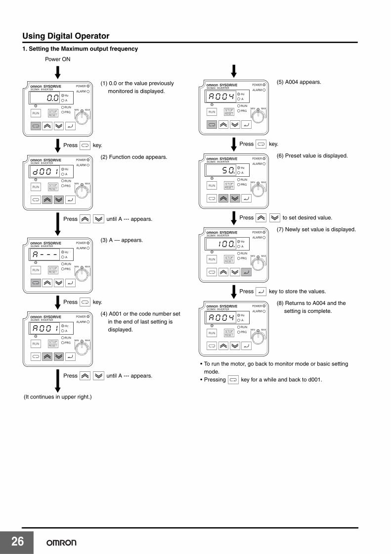
Using Digital Operator1. Setting the Maximum output frequency
Power ON
(1) 0.0 or the value previously monitored is displayed.
(2) Function code appears.
(3) A --- appears.
(4) A001 or the code number set in the end of last setting is displayed.
(It continues in upper right.)
0.0
Press key.
dk0k0k1
Press until A --- appears.
ak-k-k-
Press key.
ak0k0k1
Press until A --- appears.
(5) A004 appears.
(6) Preset value is displayed.
(7) Newly set value is displayed.
(8) Returns to A004 and the setting is complete.
• To run the motor, go back to monitor mode or basic setting mode.
• Pressing key for a while and back to d001.
ak0k0k4
Press key.
5k0.
Press to set desired value.
1k0k0.
Press key to store the values.
ak0k0k4
6
Selection
Features
SY
SD
RIV
EM
X S
eriesS
YS
DR
IVE
RX
Series
SY
SD
RIV
EO
ptionO
verview of
Inverter Selection
SY
SD
RIV
EJX
Series
Multi-functional Compact Inverters SYSDRIVE MX Series
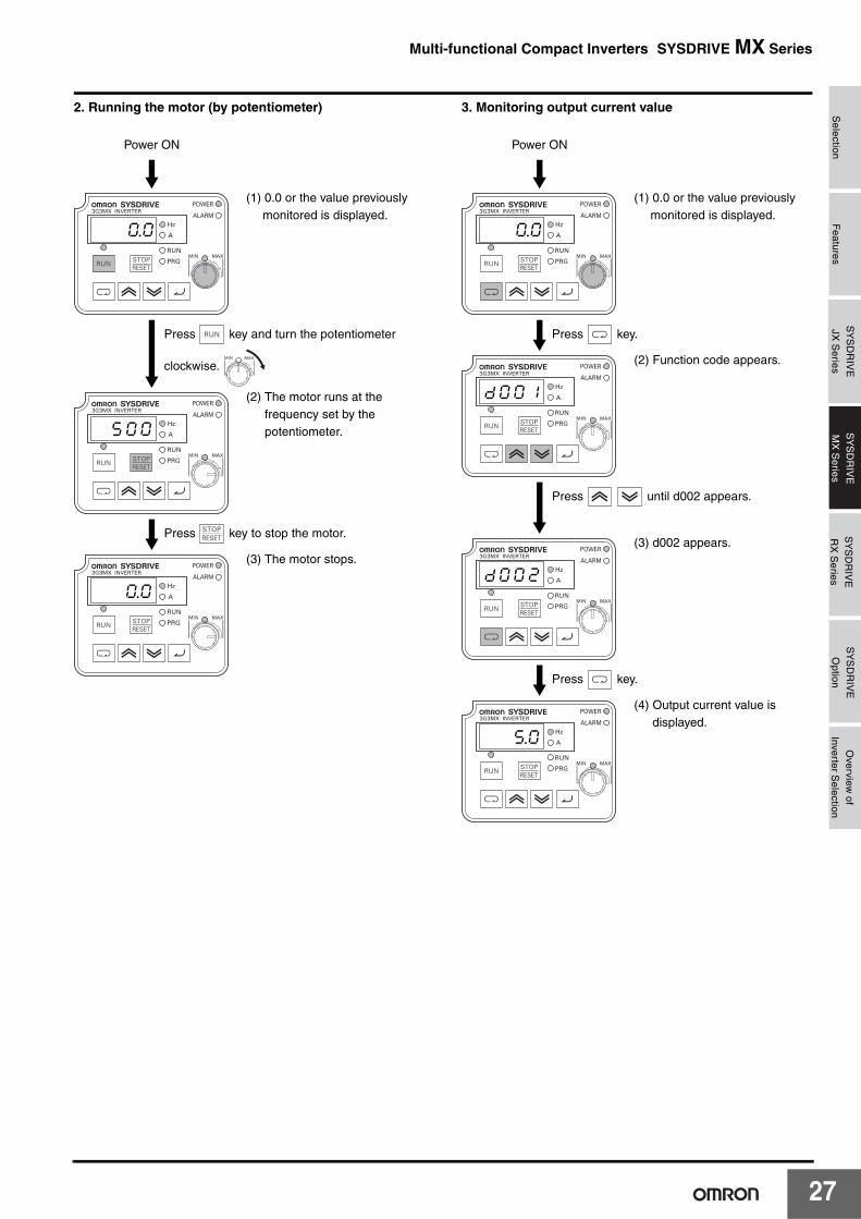
2. Running the motor (by potentiometer) 3. Monitoring output current value
Power ON
(1) 0.0 or the value previously monitored is displayed.
(2) The motor runs at the frequency set by the potentiometer.
(3) The motor stops.
0.0
Press key and turn the potentiometer
clockwise.
5k0k0
Press key to stop the motor.
0.0
Power ON
(1) 0.0 or the value previously monitored is displayed.
(2) Function code appears.
(3) d002 appears.
(4) Output current value is displayed.
0.0
Press key.
dk0k0k1
Press until d002 appears.
dk0k0k2
Press key.
5.0
27
2
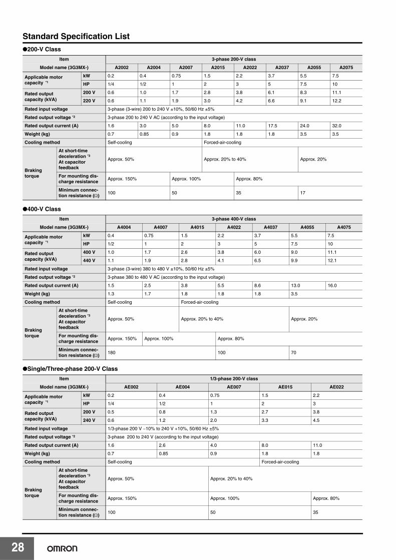
Standard Specification List●200-V Class
●400-V Class
●Single/Three-phase 200-V Class
Item 3-phase 200-V class
Model name (3G3MX-) A2002 A2004 A2007 A2015 A2022 A2037 A2055 A2075
Applicable motor capacity *1
kW 0.2 0.4 0.75 1.5 2.2 3.7 5.5 7.5
HP 1/4 1/2 1 2 3 5 7.5 10
Rated output capacity (kVA)
200 V 0.6 1.0 1.7 2.8 3.8 6.1 8.3 11.1
220 V 0.6 1.1 1.9 3.0 4.2 6.6 9.1 12.2
Rated input voltage 3-phase (3-wire) 200 to 240 V ±10%, 50/60 Hz ±5%
Rated output voltage *2 3-phase 200 to 240 V AC (according to the input voltage)
Rated output current (A) 1.6 3.0 5.0 8.0 11.0 17.5 24.0 32.0
Weight (kg) 0.7 0.85 0.9 1.8 1.8 1.8 3.5 3.5
Cooling method Self-cooling Forced-air-cooling
Brakingtorque
At short-time deceleration *3At capacitor feedback
Approx. 50% Approx. 20% to 40% Approx. 20%
For mounting dis-charge resistance
Approx. 150% Approx. 100% Approx. 80%
Minimum connec-tion resistance (Ω)
100 50 35 17
Item 3-phase 400-V class
Model name (3G3MX-) A4004 A4007 A4015 A4022 A4037 A4055 A4075
Applicable motor capacity *1
kW 0.4 0.75 1.5 2.2 3.7 5.5 7.5
HP 1/2 1 2 3 5 7.5 10
Rated output capacity (kVA)
400 V 1.0 1.7 2.6 3.8 6.0 9.0 11.1
440 V 1.1 1.9 2.8 4.1 6.5 9.9 12.1
Rated input voltage 3-phase (3-wire) 380 to 480 V ±10%, 50/60 Hz ±5%
Rated output voltage *2 3-phase 380 to 480 V AC (according to the input voltage)
Rated output current (A) 1.5 2.5 3.8 5.5 8.6 13.0 16.0
Weight (kg) 1.3 1.7 1.8 1.8 1.8 3.5
Cooling method Self-cooling Forced-air-cooling
Brakingtorque
At short-time deceleration *3At capacitor feedback
Approx. 50% Approx. 20% to 40% Approx. 20%
For mounting dis-charge resistance
Approx. 150% Approx. 100% Approx. 80%
Minimum connec-tion resistance (Ω)
180 100 70
Item 1/3-phase 200-V class
Model name (3G3MX-) AE002 AE004 AE007 AE015 AE022
Applicable motor capacity *1
kW 0.2 0.4 0.75 1.5 2.2
HP 1/4 1/2 1 2 3
Rated output capacity (kVA)
200 V 0.5 0.8 1.3 2.7 3.8
240 V 0.6 1.2 2.0 3.3 4.5
Rated input voltage 1/3-phase 200 V −10% to 240 V +10%, 50/60 Hz ±5%
Rated output voltage *2 3-phase 200 to 240 V (according to the input voltage)
Rated output current (A) 1.6 2.6 4.0 8.0 11.0
Weight (kg) 0.7 0.85 0.9 1.8 1.8
Cooling method Self-cooling Forced-air-cooling
Brakingtorque
At short-time deceleration *3At capacitor feedback
Approx. 50% Approx. 20% to 40%
For mounting dis-charge resistance
Approx. 150% Approx. 100% Approx. 80%
Minimum connec-tion resistance (Ω)
100 50 35
8

Selection
Features
SY
SD
RIV
EM
X S
eriesS
YS
DR
IVE
RX
Series
SY
SD
RIV
EO
ptionO
verview of
Inverter Selection
SY
SD
RIV
EJX
Series
Multi-functional Compact Inverters SYSDRIVE MX Series
Common Specifications
*1. The applicable motor is a 3-phase standard motor. For using any other type, be sure that the rated current does not exceed that of the Inverter.*2. Output voltage decreases according to the level of the power supply voltage.*3. The braking torque at the time of capacitor feedback is an average deceleration torque at the shortest deceleration (when it stops from 50 Hz), not a continuous
regeneration torque. Also, the average deceleration torque varies depending on the motor loss. The value is reduced in operation over 50 Hz. Note that no regen-erative braking circuit is built into the Inverter. If you need a larger regenerative torque, use the optionally available regenerative braking unit and resistor. The regenerative braking unit should be used only for short-time regeneration.
*4. Protection method complies with JEM 1030.*5. To operate the motor at over 50/60 Hz, contact the motor manufacturer to find out the maximum allowable revolution.*6. For motor stabilization, the output frequency may exceed the maximum frequency set in A004 (A204) by 2 Hz max.
Item Specifications
Enclosure rating *4 Semi-closed (IP20)
Control
Control Method Phase-to-phase sinusoidal modulation PWM
Output frequency range *5 0.5 to 400 Hz
Frequency precision *6Digital command: ±0.01% of the max. frequencyAnalog command: ±0.2% of the max. frequency (25°C ±10°C)
Frequency setting resolution
Digital setting: 0.1 Hz Analog setting: Max. frequency/1000
Voltage/Frequency characteristics
V/f characteristics (constant/reduced torque)
Overload current rating 150% for 1 min
Acceleration/Deceleration time
0.01 to 3000 s (line, S-shape curve), 2nd acceleration/deceleration setting available
Start torque 200% min./1 Hz
Carrier frequency modification range
2.0 to 14.0 kHz
DC injection brakingStarts at a frequency lower than that in deceleration via the STOP command, or via an external input. (Level and time settable.)
Protective FunctionsOvercurrent, overvoltage, undervoltage, electronic thermal, temperature error, ground-fault overcurrent at power-on state, overload limit, incoming overvoltage, external trip, memory error, CPU error, USP error, internal communication error, BRD error, overvoltage protection during deceleration, overcurrent suppression
Input signal Multi-function input
FW (forward), RV (reverse), CF1 to CF4 (multi-step speed), RS (reset), AT (current input selection), USP (USP function), EXT (external trip), OPE (forced OPE mode), STA (3-wire startup), STP (3-wire stop), F/R (3-wire forward/reverse), FRS (free run stop), JG (jogging), 2CH (2-step acceleration/deceleration), DB (external DC injection braking), SET (2nd function), UP (remote operation/accelerate), DWN (remote operation/decelerate), PID (PID selection), PIDC (PID deviation reset), PTC (thermistor input), UDC (data clear of UP/DWN function), SFT (soft lock), ADD (frequency addition), F-TM (forced terminal block), RDY (operation ready), SP-SET (special setting)
Output signal
Multi-function output
RUN (signal during operation), FA1 (frequency arrival signal 1), FA2 (frequency arrival signal 2), OL (overload warning signal), OD (PID excess deviation signal), AL (alarm signal), ODC (communication option disconnected), FBV (PID FB status output), NDc (Network error), LOG (Logic operation output)
Frequency monitorAnalog meter (0 to 10 V DC, 1 mA max.),Frequency/Current signals are selectable via the analog output terminal.
Relay output The relay (SPDT contact) outputs signals corresponding to the multi-function output.
Other functions
AVR function, V/f characteristic selection, line acceleration/deceleration, upper/lower limit, 16-step speeds, starting frequency adjustment, jogging operation, carrier frequency adjustment, PID control, frequency jump, analog gain/bias adjustment, S-shape acceleration/deceleration, electronic thermal characteristics/level adjustment, retry function, automatic torque boost, trip monitor, soft lock function, frequency conversion display, USP function, 2nd control function, motor rotation speed UP/DOWN, fan ON/OFF function
General specifica-tions
Ambient temperature−10°C to 40°C (Carrier frequency: 5 kHz max.)−10°C to 50°C (Both the carrier frequency and output current need to be reduced)
Ambient storage temperature
−20°C to 65°C (short-time temperature during transport)
Humidity 20% to 90% RH
Vibration5.9 m/s2 (0.6G), 10 to 55 Hz(Complies with the test method specified in JIS C0040 (1999).)
Location At a maximum altitude of 1,000 m; indoors (without corrosive gases or dust)
Applicable standard Complies with UL, cUL, CE standards. (Insulation distance)
Options Noise filter, AC/DC reactors, regenerative braking unit and resistor, etc.
29
3
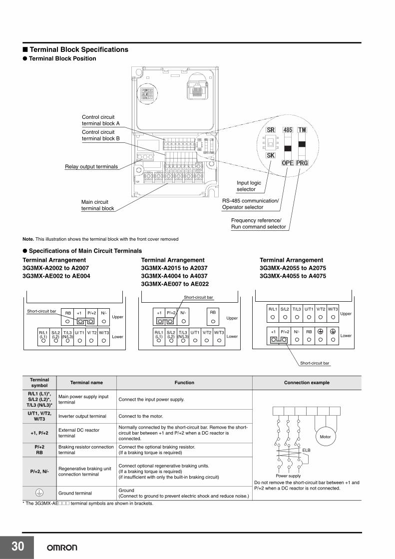
■ Terminal Block Specifications● Terminal Block Position
Note. This illustration shows the terminal block with the front cover removed
● Specifications of Main Circuit Terminals
* The 3G3MX-AE@@@ terminal symbols are shown in brackets.
Terminal symbol
Terminal name Function Connection example
R/L1 (L1)*, S/L2 (L2)*,
T/L3 (N/L3)*
Main power supply input terminal
Connect the input power supply.
Do not remove the short-circuit bar between +1 andP/+2 when a DC reactor is not connected.
U/T1, V/T2, W/T3
Inverter output terminal Connect to the motor.
+1, P/+2External DC reactor terminal
Normally connected by the short-circuit bar. Remove the short-circuit bar between +1 and P/+2 when a DC reactor is connected.
P/+2RB
Braking resistor connection terminal
Connect the optional braking resistor. (If a braking torque is required)
P/+2, N/-Regenerative braking unit connection terminal
Connect optional regenerative braking units.(If a braking torque is required)(if insufficient with only the built-in braking circuit)
Ground terminalGround (Connect to ground to prevent electric shock and reduce noise.)
Control circuit terminal block A
Main circuit terminal block
Relay output terminals
Input logic selector
Control circuit terminal block B
RS-485 communication/Operator selector
Frequency reference/Run command selector
RB +1
R/L1(L1)
S/L2(L2)
T/L3(N/L3)
Upper
Lower
Short-circuit bar P/+2 N/-
U/ T1 V/ T2 W/T3
Upper
Lower
Short-circuit bar
RB+1
R/L1(L1)
S/L2(L2)
T/L3(N/L3)
P/+2 N/-
U/T1 V/T2 W/T3
Upper
Lower+1 P/+2 N/- RB
S/L2 T/L3 U/T1 V/T2 W/T3R/L1
Short-circuit bar
Terminal Arrangement3G3MX-A2002 to A20073G3MX-AE002 to AE004
Terminal Arrangement3G3MX-A2015 to A20373G3MX-A4004 to A40373G3MX-AE007 to AE022
Terminal Arrangement3G3MX-A2055 to A20753G3MX-A4055 to A4075
Power supply
ELB
Motor
0
Selection
Features
SY
SD
RIV
EM
X S
eriesS
YS
DR
IVE
RX
Series
SY
SD
RIV
EO
ptionO
verview of
Inverter Selection
SY
SD
RIV
EJX
Series
Multi-functional Compact Inverters SYSDRIVE MX Series
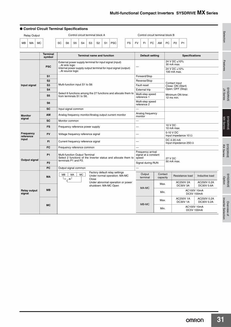
● Control Circuit Terminal Specifications
Terminal symbol Terminal name and function Default setting Specifications
Input signal
PSC
External power supply terminal for input signal (input) ...At sink logicInternal power supply output terminal for input signal (output) ...At source logic
---
24 V DC ±10%30 mA max.
24 V DC ±10%100 mA max.
S1
Multi-function input S1 to S6
Select 6 functions among the 27 functions and allocate them tofrom terminals S1 to S6.
Forward/Stop
Contact inputClose: ON (Start)Open: OFF (Stop)
Minimum ON time:12 ms min.
S2 Reverse/Stop
S3 Fault reset
S4 External trip
S5 Multi-step speed reference 1
S6 Multi-step speed reference 2
SC Input signal common ---
Monitor signal
AM Analog frequency monitor/Analog output current monitor Analog frequency monitor
SC Monitor common ---
Frequency reference input
FS Frequency reference power supply --- 10 V DC10 mA max.
FV Voltage frequency reference signal --- 0-10 V DCInput impedance 10 Ω
FI Current frequency reference signal --- DC 4-20 mAInput impedance 250 Ω
FC Frequency reference common ---
Output signal
P1 Multi-function Output TerminalSelect 2 functions of the Inverter status and allocate them toterminals P1 and P2.
Frequency arrival signal at a constant speed 27 V DC
50 mA max.P2 Signal during RUN
PC Output signal common ---
Relay output signal
MA
Factory default relay settingsUnder normal operation: MA-MC CloseUnder abnormal operation or power shutdown: MA-MC Open
MB
MC
SC S6 S5 S4 S3 S2 S1 PSC
Relay Output
FS FV FI FC AM PC P2 P1MB MA MC
Control circuit terminal block A Control circuit terminal block B
MB MA MC Output terminal
Contact capacity
Resistance load Inductive load
MA-MC
Max.AC250V 2ADC30V 3A
AC250V 0.2ADC30V 0.6A
Min.AC100V 10mADC5V 100mA
MB-MC
Max.AC250V 1ADC30V 1A
AC250V 0.2ADC30V 0.2A
Min.AC100V 10mADC5V 100mA
31
3
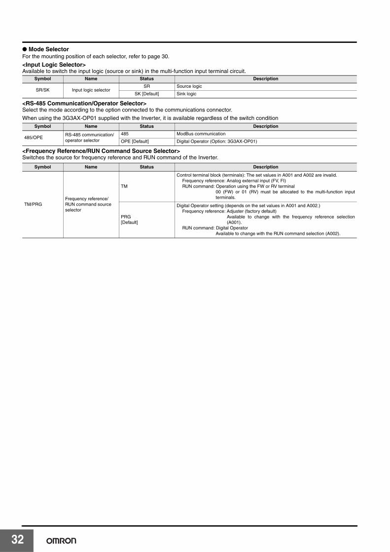
● Mode SelectorFor the mounting position of each selector, refer to page 30.
<Input Logic Selector>Available to switch the input logic (source or sink) in the multi-function input terminal circuit.
<RS-485 Communication/Operator Selector>Select the mode according to the option connected to the communications connector.
When using the 3G3AX-OP01 supplied with the Inverter, it is available regardless of the switch condition
<Frequency Reference/RUN Command Source Selector>Switches the source for frequency reference and RUN command of the Inverter.
Symbol Name Status Description
SR/SK Input logic selectorSR Source logic
SK [Default] Sink logic
Symbol Name Status Description
485/OPERS-485 communication/operator selector
485 ModBus communication
OPE [Default] Digital Operator (Option: 3G3AX-OP01)
Symbol Name Status Description
TM/PRGFrequency reference/RUN command source selector
TM
Control terminal block (terminals): The set values in A001 and A002 are invalid.Frequency reference: Analog external input (FV, FI)RUN command: Operation using the FW or RV terminal
00 (FW) or 01 (RV) must be allocated to the multi-function inputterminals.
PRG[Default]
Digital Operator setting (depends on the set values in A001 and A002.)Frequency reference: Adjuster (factory default)
Available to change with the frequency reference selection(A001).
RUN command: Digital OperatorAvailable to change with the RUN command selection (A002).
2
Selection
Features
SY
SD
RIV
EM
X S
eriesS
YS
DR
IVE
RX
Series
SY
SD
RIV
EO
ptionO
verview of
Inverter Selection
SY
SD
RIV
EJX
Series
Multi-functional Compact Inverters SYSDRIVE MX Series
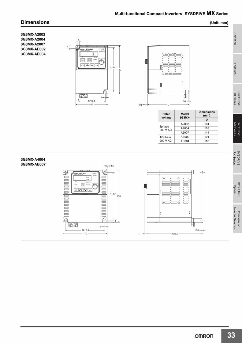
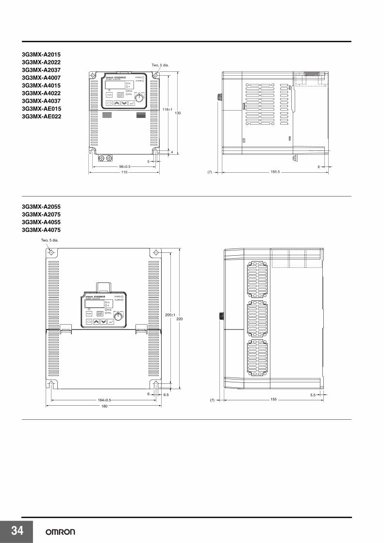
Dimensions (Unit: mm)
D
2.6
(7)80
120
5
67±0.5
6
110±1
5
3G3MX-A20023G3MX-A20043G3MX-A20073G3MX-AE0023G3MX-AE004
Rated voltage
Model3G3MX-
Dimensions (mm)
D
3phase200 V AC
A2002 104
A2004 118
A2007 141
1/3phase200 V AC
AE002 104
AE004 118
4
138.5
98±0.5
(7) 110
130 118±1
5
Two, 5 dia.
2.6
3G3MX-A40043G3MX-AE007
33
3
5
4
98±0.5
130
Two, 5 dia.
110 (7) 165.56
118±1
3G3MX-A20153G3MX-A20223G3MX-A20373G3MX-A40073G3MX-A40153G3MX-A40223G3MX-A40373G3MX-AE0153G3MX-AE022
180
Two, 5 dia.
164±0.5
205±1220
6 6.5
(7) 1555.5
3G3MX-A20553G3MX-A20753G3MX-A40553G3MX-A4075
4
Selection
Features
SY
SD
RIV
EM
X S
eriesS
YS
DR
IVE
RX
Series
SY
SD
RIV
EO
ptionO
verview of
Inverter Selection
SY
SD
RIV
EJX
Series
Multi-functional Compact Inverters SYSDRIVE MX Series
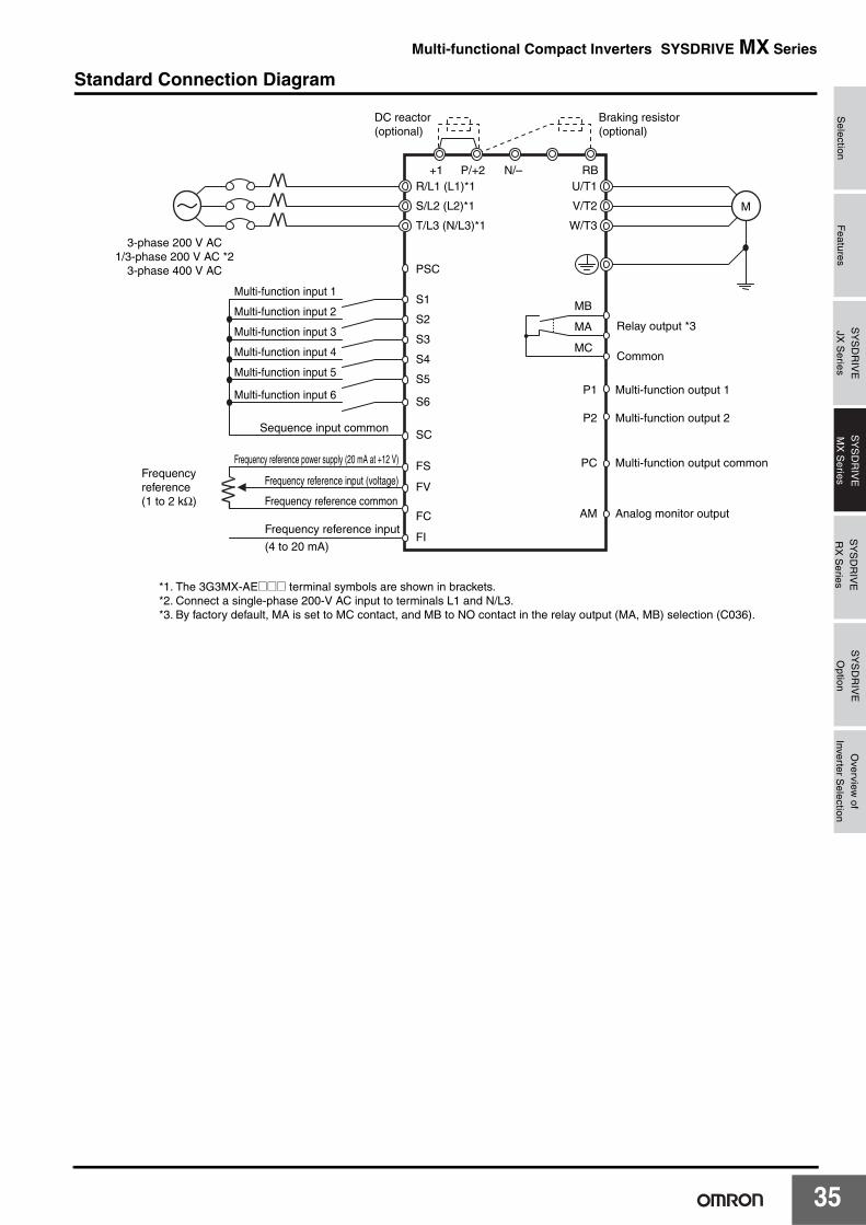
Standard Connection Diagram
DC reactor (optional)
3-phase 200 V AC1/3-phase 200 V AC *2
3-phase 400 V AC
Multi-function input 1
Multi-function input 2
Multi-function input 3
Multi-function input 4
Multi-function input 5
Frequency reference power supply (20 mA at +12 V)Frequency reference (1 to 2 kΩ)
Frequency reference input (voltage)
Frequency reference input
(4 to 20 mA)
*1. The 3G3MX-AE@@@ terminal symbols are shown in brackets.*2. Connect a single-phase 200-V AC input to terminals L1 and N/L3.*3. By factory default, MA is set to MC contact, and MB to NO contact in the relay output (MA, MB) selection (C036).
Frequency reference common
Sequence input common
M
R/L1 (L1)*1+1 P/+2
Braking resistor(optional)
RBN/–
T/L3 (N/L3)*1
S/L2 (L2)*1
U/T1
W/T3
P2
PC
Multi-function output 2
P1 Multi-function output 1
Multi-function output common
AM Analog monitor output
Relay output *3
Common
V/T2
PSC
S2
S1
S5
SC
FS
FI
FC
FV
S4
S3
Multi-function input 6S6
MB
MA
MC
35
3
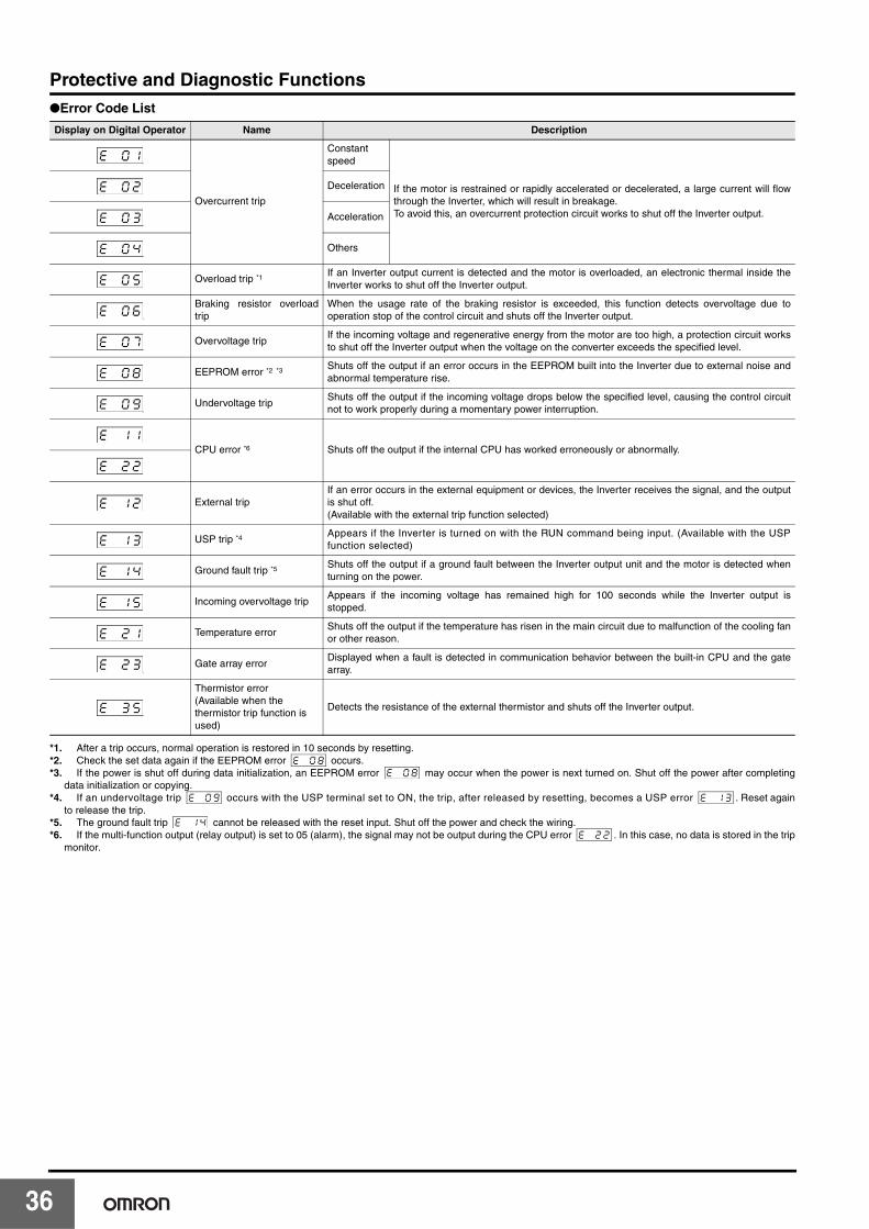
Protective and Diagnostic Functions●Error Code List
*1. After a trip occurs, normal operation is restored in 10 seconds by resetting. *2. Check the set data again if the EEPROM error occurs.*3. If the power is shut off during data initialization, an EEPROM error may occur when the power is next turned on. Shut off the power after completing
data initialization or copying.*4. If an undervoltage trip occurs with the USP terminal set to ON, the trip, after released by resetting, becomes a USP error . Reset again
to release the trip.*5. The ground fault trip cannot be released with the reset input. Shut off the power and check the wiring.*6. If the multi-function output (relay output) is set to 05 (alarm), the signal may not be output during the CPU error . In this case, no data is stored in the trip
monitor.
Display on Digital Operator Name Description
Overcurrent trip
Constantspeed
If the motor is restrained or rapidly accelerated or decelerated, a large current will flowthrough the Inverter, which will result in breakage.To avoid this, an overcurrent protection circuit works to shut off the Inverter output.
Deceleration
Acceleration
Others
Overload trip *1If an Inverter output current is detected and the motor is overloaded, an electronic thermal inside theInverter works to shut off the Inverter output.
Braking resistor overloadtrip
When the usage rate of the braking resistor is exceeded, this function detects overvoltage due tooperation stop of the control circuit and shuts off the Inverter output.
Overvoltage tripIf the incoming voltage and regenerative energy from the motor are too high, a protection circuit worksto shut off the Inverter output when the voltage on the converter exceeds the specified level.
EEPROM error *2 *3 Shuts off the output if an error occurs in the EEPROM built into the Inverter due to external noise andabnormal temperature rise.
Undervoltage tripShuts off the output if the incoming voltage drops below the specified level, causing the control circuitnot to work properly during a momentary power interruption.
CPU error *6 Shuts off the output if the internal CPU has worked erroneously or abnormally.
External tripIf an error occurs in the external equipment or devices, the Inverter receives the signal, and the outputis shut off.(Available with the external trip function selected)
USP trip *4Appears if the Inverter is turned on with the RUN command being input. (Available with the USPfunction selected)
Ground fault trip *5Shuts off the output if a ground fault between the Inverter output unit and the motor is detected whenturning on the power.
Incoming overvoltage tripAppears if the incoming voltage has remained high for 100 seconds while the Inverter output isstopped.
Temperature errorShuts off the output if the temperature has risen in the main circuit due to malfunction of the cooling fanor other reason.
Gate array errorDisplayed when a fault is detected in communication behavior between the built-in CPU and the gatearray.
Thermistor error(Available when the thermistor trip function is used)
Detects the resistance of the external thermistor and shuts off the Inverter output.
ek k0k1
ek k0k2
ek k0k3
ek k0k4
ek k0k5
ek k0k6
ek k0k7
ek k0k8
ek k0k9
ek k1k1
ek k2k2
ek k1k2
ek k1k3
ek k1k4
ek k1k5
ek k2k1
ek k2k3
ek k3k5
ek k0k8ek k0k8
ek k0k9 ek k1k3
ek k1k4ek k2k2
6
Selection
Features
SY
SD
RIV
EM
X S
eriesS
YS
DR
IVE
RX
Series
SY
SD
RIV
EO
ptionO
verview of
Inverter Selection
SY
SD
RIV
EJX
Series
Multi-functional Compact Inverters SYSDRIVE MX Series
Model Number Explanation
Standard Models
International Standards (EC Directives and UL/cUL Standards)The 3G3MX Inverter meets the EC Directives and UL/cUL standard requirements for worldwide use.
Rated voltage Enclosure rating Max. applicable motor capacity Model
3-phase 200 V AC
IP20
0.2 kW 3G3MX-A2002
0.4 kW 3G3MX-A2004
0.75 kW 3G3MX-A2007
1.5 kW 3G3MX-A2015
2.2 kW 3G3MX-A2022
3.7 kW 3G3MX-A2037
5.5 kW 3G3MX-A2055
7.5 kW 3G3MX-A2075
1/3-phase 200 V AC
0.2 kW 3G3MX-AE002
0.4 kW 3G3MX-AE004
0.75 kW 3G3MX-AE007
1.5 kW 3G3MX-AE015
2.2 kW 3G3MX-AE022
3-phase 400 V AC
0.4 kW 3G3MX-A4004
0.75 kW 3G3MX-A4007
1.5 kW 3G3MX-A4015
2.2 kW 3G3MX-A4022
3.7 kW 3G3MX-A4037
5.5 kW 3G3MX-A4055
7.5 kW 3G3MX-A4075
Classification Applicable standard
EC DirectivesEMC Directive EN61800-3: 2004
Low-voltage Directive EN61800-5-1: 2003
UL/cUL Standards UL508C
Voltage Class
3G3MX - A � � � �
002
004
007
0.2 kW
0.4 kW
0.75 kW
022
037
2.2 kW
3.7 kW
015 1.5 kW
055
075
5.5 kW
7.5 kW
2
4
3-phase 200 V AC
3-phase 400 V AC
E 1-/3-phase 200 V AC
MX-seriesInverter
Maximum Motor Capacity
37
38
Advanced General-purpose Inverters
SYSDRIVE RX Series
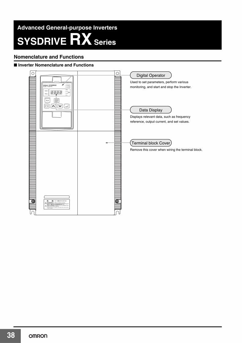
Nomenclature and Functions
■ Inverter Nomenclature and Functions
Used to set parameters, perform various
monitoring, and start and stop the Inverter.
Displays relevant data, such as frequency
reference, output current, and set values.
Digital Operator
Data Display
Remove this cover when wiring the terminal block.
Terminal block Cover
Selection
Features
SY
SD
RIV
EJX
Series
SY
SD
RIV
EM
X S
eriesS
YS
DR
IVE
RX
Series
SY
SD
RIV
EO
ption
Overview
ofInverter S
election
Advanced General-purpose Inverters SYSDRIVE RX Series
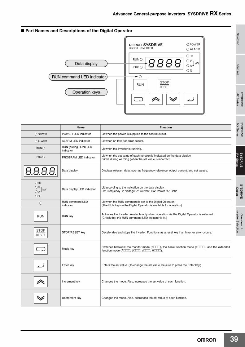
■ Part Names and Descriptions of the Digital Operator
Name Function
POWER LED indicator Lit when the power is supplied to the control circuit.
ALARM LED indicator Lit when an Inverter error occurs.
RUN (during RUN) LED indicator
Lit when the Inverter is running.
PROGRAM LED indicatorLit when the set value of each function is indicated on the data display.Blinks during warning (when the set value is incorrect).
Data display Displays relevant data, such as frequency reference, output current, and set values.
Data display LED indicatorLit according to the indication on the data display.Hz: Frequency V: Voltage A: Current kW: Power %: Ratio
RUN command LED indicator
Lit when the RUN command is set to the Digital Operator.(The RUN key on the Digital Operator is available for operation)
RUN keyActivates the Inverter. Available only when operation via the Digital Operator is selected.(Check that the RUN command LED indicator is lit.)
STOP/RESET key Decelerates and stops the Inverter. Functions as a reset key if an Inverter error occurs.
Mode keySwitches between: the monitor mode (d@@@), the basic function mode (F@@@), and the extendedfunction mode (A@@@, b@@@, c@@@, H@@@).
Enter key Enters the set value. (To change the set value, be sure to press the Enter key.)
Increment key Changes the mode. Also, increases the set value of each function.
Decrement key Changes the mode. Also, decreases the set value of each function.
8k8k8k8kData display
Operation keys
RUN command LED indicator
8.8.8.8.
39

4
Using Digital Operator
■ Setting output frequency
Power ON
(1) 0.0 or the value previously monitored is displayed.
(2) Function code appears.
(3) F001 appears.
(It continues in upper right.)
0.0k0k
Press key.
Ddk0k0k1k
Press until F001 appears.
Dfk0k0k1k
Press key.
(4) Preset value is displayed.
(5) Newly set value is displayed.
(6) Set end. (Back to F001)
D0.0k0k
Press to set desired value.
D6k0.0k0k
Press key to store the value.
Dfk0k0k1k
0
Selection
Features
SY
SD
RIV
EJX
Series
SY
SD
RIV
EM
X S
eriesS
YS
DR
IVE
RX
Series
SY
SD
RIV
EO
ption
Overview
ofInverter S
election
Advanced General-purpose Inverters SYSDRIVE RX Series
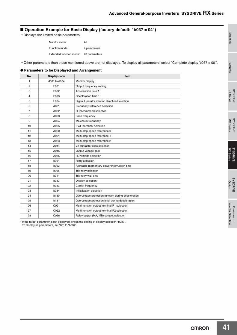
■ Operation Example for Basic Display (factory default: "b037 = 04")• Displays the limited basic parameters.
• Other parameters than those mentioned above are not displayed. To display all parameters, select "Complete display 'b037 = 00'".
● Parameters to be Displayed and Arrangement
* If the target parameter is not displayed, check the setting of display selection "b037".To display all parameters, set "00" to "b037".
Monitor mode: All
Function mode: 4 parameters
Extended function mode: 20 parameters
No. Display code Item
1 d001 to d104 Monitor display
2 F001 Output frequency setting
3 F002 Acceleration time 1
4 F003 Deceleration time 1
5 F004 Digital Operator rotation direction Selection
6 A001 Frequency reference selection
7 A002 RUN command selection
8 A003 Base frequency
9 A004 Maximum frequency
10 A005 FV/FI terminal selection
11 A020 Multi-step speed reference 0
12 A021 Multi-step speed reference 1
13 A023 Multi-step speed reference 2
14 A044 V/f characteristics selection
15 A045 Output voltage gain
16 A085 RUN mode selection
17 b001 Retry selection
18 b002 Allowable momentary power interruption time
19 b008 Trip retry selection
20 b011 Trip retry wait time
21 b037 Display selection *
22 b083 Carrier frequency
23 b084 Initialization selection
24 b130 Overvoltage protection function during deceleration
25 b131 Overvoltage protection level during deceleration
26 C021 Multi-function output terminal P1 selection
27 C022 Multi-function output terminal P2 selection
28 C036 Relay output (MA, MB) contact selection
41
4
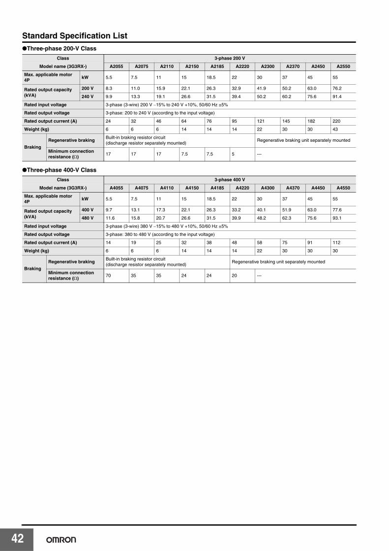
Standard Specification List●Three-phase 200-V Class
●Three-phase 400-V Class
Class 3-phase 200 V
Model name (3G3RX-) A2055 A2075 A2110 A2150 A2185 A2220 A2300 A2370 A2450 A2550
Max. applicable motor 4P
kW 5.5 7.5 11 15 18.5 22 30 37 45 55
Rated output capacity (kVA)
200 V 8.3 11.0 15.9 22.1 26.3 32.9 41.9 50.2 63.0 76.2
240 V 9.9 13.3 19.1 26.6 31.5 39.4 50.2 60.2 75.6 91.4
Rated input voltage 3-phase (3-wire) 200 V −15% to 240 V +10%, 50/60 Hz ±5%
Rated output voltage 3-phase: 200 to 240 V (according to the input voltage)
Rated output current (A) 24 32 46 64 76 95 121 145 182 220
Weight (kg) 6 6 6 14 14 14 22 30 30 43
Braking
Regenerative brakingBuilt-in braking resistor circuit (discharge resistor separately mounted)
Regenerative braking unit separately mounted
Minimum connection resistance (Ω)
17 17 17 7.5 7.5 5 ---
Class 3-phase 400 V
Model name (3G3RX-) A4055 A4075 A4110 A4150 A4185 A4220 A4300 A4370 A4450 A4550
Max. applicable motor 4P
kW 5.5 7.5 11 15 18.5 22 30 37 45 55
Rated output capacity (kVA)
400 V 9.7 13.1 17.3 22.1 26.3 33.2 40.1 51.9 63.0 77.6
480 V 11.6 15.8 20.7 26.6 31.5 39.9 48.2 62.3 75.6 93.1
Rated input voltage 3-phase (3-wire) 380 V −15% to 480 V +10%, 50/60 Hz ±5%
Rated output voltage 3-phase: 380 to 480 V (according to the input voltage)
Rated output current (A) 14 19 25 32 38 48 58 75 91 112
Weight (kg) 6 6 6 14 14 14 22 30 30 30
Braking
Regenerative brakingBuilt-in braking resistor circuit (discharge resistor separately mounted)
Regenerative braking unit separately mounted
Minimum connection resistance (Ω)
70 35 35 24 24 20 ---
2

Selection
Features
SY
SD
RIV
EJX
Series
SY
SD
RIV
EM
X S
eriesS
YS
DR
IVE
RX
Series
SY
SD
RIV
EO
ption
Overview
ofInverter S
election
Advanced General-purpose Inverters SYSDRIVE RX Series
Common Specification
ItemSpecifications
Enclosure rating IP20
Cooling method Forced air cooling
Control method Phase-to-phase sinusoidal modulation PWM
Output frequency range 0.1 to 400Hz
Frequency precisionDigital command: ±0.01% of the max. frequencyAnalog command: ±0.2% of the max. frequency (25°C ±10°C)
Frequency resolution
Digital setting: 0.01 HzAnalog setting: Max. frequency/4000(Terminal FV: 12 bits/0 to +10 V), (Terminal FE: 12 bits/−10 to +10 V), (Terminal FI: 12 bits/0 to +20 mA)
Voltage/Frequency characteristicsV/f optionally changeable at base frequencies of 30 to 400 Hz, V/f braking constant torque, reduction torque, sensorless vector control, sensor-less vector control at 0 Hz
Speed fluctuation ±0.5% (under sensor-less vector control or sensorless vector control at 0 Hz)
Overload current rating 150%/60 s, 200%/3 s
Acceleration/Deceleration time 0.01 to 3600.0 s (line/curve selection)
Starting torque
200%/0.3 Hz(under sensorless vector control or sensor-less vector control at 0 Hz)150%/Torque at 0 Hz (under sensor-less vector control at 0 Hz, or when the motor with one frame fewer than the maximum applicable motor is connected)
DC injection brakingOperates when the starting frequency is lower than that in deceleration via the STOP command, when the frequency reference is lower than the operation frequency, or via an external input (braking power, time, and frequency settable)
InputMulti-function input
8 terminals, NO/NC switchable, sink/source logic switchable[Terminal function] 8 functions can be selected from among 61.Reverse (RV), Multi-step speed 1 (CF1), Multi-step speed 2 (CF2), Multi-step speed 3 (CF3), Multi-step speed 4 (CF4), Jogging (JG), External DC injection braking (DB), 2nd control (SET), 2-step acceleration/deceleration (2CH), Free-run stop (FRS), External trip (EXT), USP function (USP), Commercial switch (CS), Soft lock (SFT), Analog input selection (AT), 3rd control (SET3), Reset (RS), 3-wire startup (STA), 3-wire stop (STP), 3-wire forward/reverse (F/R), PID disabled (PID), PID integral reset (PIDC), Control gain switching (CAS), UP/DWN function accelerated (UP), UP/DWN function decelerated (DWN), UP/DWN function data clear (UDC), Forced operator (OPE), Multi-step speed bit 1 (SF1), Multi-step speed bit 2 (SF2), Multi-step speed bit 3 (SF3), Multi-step speed bit 4 (SF4), Multi-step speed bit 5 (SF5), Multi-step speed bit 6 (SF6), Multi-step speed bit 7 (SF7), Overload limit switching (OLR), Torque limit enabled (TL), Torque limit switching 1 (TRQ1), Torque limit switching 2 (TRQ2), P/PI switching (PPI), Brake confirmation (BOK), Orientation (ORT), LAD cancel (LAC), Position deviation clear (PCLR), Pulse train position command input permission (STAT), Frequency addition function (ADD), Forced terminal (F-TM), Torque reference input permission (ATR), Integrated power clear (KHC), Servo ON (SON), Preliminary excitation (FOC), Position command selection 1 (CP1), Position command selection 2 (CP2), Position command selection 3 (CP3), Zero return limit signal (ORL), Zero return startup signal (ORG), Forward driving stop (FOT), Reverse driving stop (ROT), Speed/Position switching (SPD), Pulse counter (PCNT), Pulse counter clear (PCC), Analog command held (AHD), No allocation (no)
Thermistor input terminal 1 terminal (Positive/Negative temperature coefficient of resistance element switchable)
Output
Multi-function output
5 open collector output terminals: NO/NC switchable, sink/source logic switchable1 relay (SPDT contact) output terminal: NO/NC switchable[Terminal function] 6 functions can be selected from among 45.During operation (RUN), Constant speed reached (FA1), Set frequency exceeded (FA2), Overload warning (OL), Excessive PID deviation (OD), Alarm signal (AL), Set frequency only (FA3), Overtorque (OTQ), Signal during momentary power interruption (IP), Signal during undervoltage (UV), Torque limit (TRQ), RUN time over (RNT), Power ON time over (ONT), Thermal warning (THM), Brake release (BRK), Brake error (BER), Zero-speed signal (ZS), Excessive speed deviation (DSE), Position ready (POK), Set frequency exceeded 2 (FA4), Set frequency only 2 (FA5), Overload warning 2 (OL2), Analog FV disconnection detection (FVDc), Analog FI disconnection detection (FIDc), Analog FE disconnection detection (FEDc), PID FB status output (FBV), Network error (NDc), Logic operation output 1 (LOG1), Logic operation output 2 (LOG2), Logic operation output 3 (LOG3), Logic operation output 4 (LOG4), Logic operation output 5 (LOG5), Logic operation output 6 (LOG6), Capacitor life warning (WAC), Cooling fin overheat warning (WAF), Starting contact signal (FR), Cooling fin overheat warning (OHF), Low current signal (LOC), Operation ready (IRDY), During forward operation (FWR), During reverse operation (RVR), Fatal fault (MJA), Window comparator FV (WCFV), Window comparator FI (WCFI), Window comparator FE (WCFE), Alarm codes 0 to 3 (AC0 to AC3)
Multi-function monitor output terminal
Analog voltage output, Analog current output, Pulse train output (A-F, D-F {multiplied by "n", pulse output only}, A, T, V, P, etc.)
Display monitorOutput frequency, Output current, Output torque, Frequency conversion value, Trip record, I/O terminal status, Electric power, etc.
Other functions
V/f free setting (7), Upper/lower frequency limit, Frequency jump, Curve acceleration/deceleration, Manual torque boost level/break, Energy-saving operation, Analog meter adjustment, Starting frequency, Carrier frequency adjustment, Electronic thermal function, (free setting available), External start/end (frequency/rate), Analog input selection, Trip retry, Restart during momentary power interruption, Various signal outputs, Reduced voltage startup, Overload limit, Initialization value setting, Automatic deceleration at power-off, AVR function, Fuzzy acceleration/deceleration, Auto tuning (Online/Offline), High-torque multi-operation control (sensor-less vector control of two monitors with one Inverter)
Carrier frequency modification range 0.5 to 15 kHz
Protective functions
Overcurrent protection, Overvoltage protection, Undervoltage protection, Electronic thermal protection, Temperature error protection, Momentary power interruption/Power interruption protection, Input open-phase protection, Braking resistor overload protection, Ground-fault overcurrent detection at power-on, USP error, External trip, Emergency shutoff trip, CT error, Communication error, Option error, etc.
43

4
*Complies with the test method specified in JIS C0040 (1999).Note: Insulation distance complies with UL/CE standards.
Operating environ-ment
Ambient/Storage temperature/Humidity
−10°C to 50°C/−20°C to 65°C/20% to 90% RH (with no condensation)
Vibration *3G3RX-A055/-A075/-A110/-A150/-A185/-A220: 5.9 m/s2 (0.6G), 10 to 55 Hz3G3RX-A300/-A370/-A450/-A550: 2.94 m/s2 (0.3G), 10 to 55 Hz
Location At a maximum altitude of 1,000 m; indoors (without corrosive gases or dust)
OptionsFeedback option Sensor vector control
Digital input option 4-digit BCD, 16-bit binary
Other options Braking resistor, AC/DC reactor, Noise filter, Digital Operator cables, Regenerative braking unit, etc.
ItemSpecifications
4
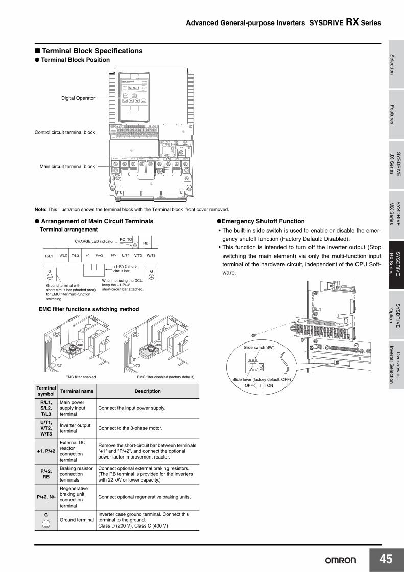
Selection
Features
SY
SD
RIV
EJX
Series
SY
SD
RIV
EM
X S
eriesS
YS
DR
IVE
RX
Series
SY
SD
RIV
EO
ption
Overview
ofInverter S
election
Advanced General-purpose Inverters SYSDRIVE RX Series
■ Terminal Block Specifications● Terminal Block Position
Note: This illustration shows the terminal block with the Terminal block front cover removed.
● Arrangement of Main Circuit Terminals ●Emergency Shutoff Function• The built-in slide switch is used to enable or disable the emer-
gency shutoff function (Factory Default: Disabled).
• This function is intended to turn off the Inverter output (Stop
switching the main element) via only the multi-function input
terminal of the hardware circuit, independent of the CPU Soft-
ware.
Digital Operator
Control circuit terminal block
Main circuit terminal block
Terminal symbol
Terminal name Description
R/L1, S/L2, T/L3
Main power supply input terminal
Connect the input power supply.
U/T1,V/T2,W/T3
Inverter output terminal
Connect to the 3-phase motor.
+1, P/+2
External DC reactor connection terminal
Remove the short-circuit bar between terminals "+1" and "P/+2", and connect the optional power factor improvement reactor.
P/+2, RB
Braking resistor connection terminals
Connect optional external braking resistors. (The RB terminal is provided for the Inverters with 22 kW or lower capacity.)
P/+2, N/-
Regenerative braking unit connection terminal
Connect optional regenerative braking units.
GGround terminal
Inverter case ground terminal. Connect this terminal to the ground.Class D (200 V), Class C (400 V)
GG
Terminal arrangement
RO TORB
R/L1 S/L2 T/L3 +1 P/+2 N/- U/T1 V/T2 W/T3
Ground terminal with short-circuit bar (shaded area)for EMC filter multi-function switching
+1-P/+2 short-circuit bar
When not using the DCL, keep the +1-P/+2 short-circuit bar attached.
CHARGE LED indicator
EMC filter enabled EMC filter disabled (factory default)
EMC filter functions switching method
ON
Slide switch SW1
Slide lever (factory default: OFF)
ONOFF
45
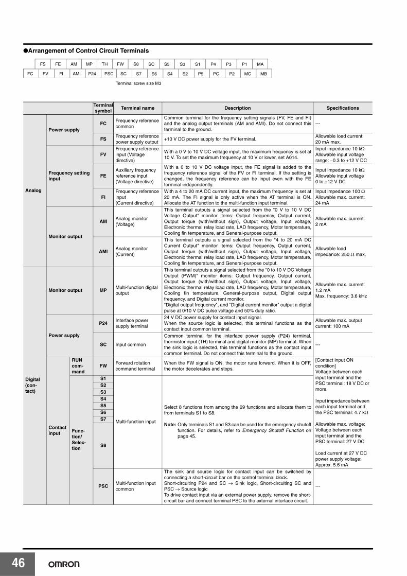
4
●Arrangement of Control Circuit Terminals
Terminal symbol
Terminal name Description Specifications
Analog
Power supplyFC
Frequency reference common
Common terminal for the frequency setting signals (FV, FE and FI)and the analog output terminals (AM and AMI). Do not connect thisterminal to the ground.
---
FSFrequency reference power supply output
+10 V DC power supply for the FV terminal.Allowable load current: 20 mA max.
Frequency setting input
FVFrequency reference input (Voltage directive)
With a 0 V to 10 V DC voltage input, the maximum frequency is set at10 V. To set the maximum frequency at 10 V or lower, set A014.
Input impedance 10 kΩAllowable input voltage range: −0.3 to +12 V DC
FEAuxiliary frequency reference input(Voltage directive)
With a 0 to 10 V DC voltage input, the FE signal is added to thefrequency reference signal of the FV or FI terminal. If the setting ischanged, the frequency reference can be input even with the FEterminal independently.
Input impedance 10 kΩAllowable input voltage0 to ±12 V DC
FIFrequency reference input(Current directive)
With a 4 to 20 mA DC current input, the maximum frequency is set at20 mA. The FI signal is only active when the AT terminal is ON.Allocate the AT function to the multi-function input terminal.
Input impedance 100 ΩAllowable max. current: 24 mA
Monitor output
AMAnalog monitor(Voltage)
This terminal outputs a signal selected from the "0 V to 10 V DCVoltage Output" monitor items: Output frequency, Output current,Output torque (with/without sign), Output voltage, Input voltage,Electronic thermal relay load rate, LAD frequency, Motor temperature,Cooling fin temperature, and General-purpose output.
Allowable max. current: 2 mA
AMIAnalog monitor(Current)
This terminal outputs a signal selected from the "4 to 20 mA DCCurrent Output" monitor items: Output frequency, Output current,Output torque (with/without sign), Output voltage, Input voltage,Electronic thermal relay load rate, LAD frequency, Motor temperature,Cooling fin temperature, and General-purpose output.
Allowable load impedance: 250 Ω max.
Digital (con-tact)
Monitor output MPMulti-function digital output
This terminal outputs a signal selected from the "0 to 10 V DC VoltageOutput (PWM)" monitor items: Output frequency, Output current,Output torque (with/without sign), Output voltage, Input voltage,Electronic thermal relay load rate, LAD frequency, Motor temperature,Cooling fin temperature, General-purpose output, Digital outputfrequency, and Digital current monitor."Digital output frequency", and "Digital current monitor" output a digitalpulse at 0/10 V DC pulse voltage and 50% duty ratio.
Allowable max. current: 1.2 mAMax. frequency: 3.6 kHz
Power supply
P24Interface power supply terminal
24 V DC power supply for contact input signal.When the source logic is selected, this terminal functions as thecontact input common terminal.
Allowable max. output current: 100 mA
SC Input common
Common terminal for the interface power supply (P24) terminal,thermistor input (TH) terminal and digital monitor (MP) terminal. Whenthe sink logic is selected, this terminal functions as the contact inputcommon terminal. Do not connect this terminal to the ground.
---
Contact input
RUN com-mand
FWForward rotation command terminal
When the FW signal is ON, the motor runs forward. When it is OFF,the motor decelerates and stops.
[Contact input ON condition] Voltage between each input terminal and the PSC terminal: 18 V DC or more.
Input impedance between each input terminal and the PSC terminal: 4.7 kΩ
Allowable max. voltage:Voltage between each input terminal and the PSC terminal: 27 V DC
Load current at 27 V DC power supply voltage:Approx. 5.6 mA
Func-tion/Selec-tion
S1
Multi-function input
Select 8 functions from among the 69 functions and allocate them tofrom terminals S1 to S8.
Note: Only terminals S1 and S3 can be used for the emergency shutofffunction. For details, refer to Emergency Shutoff Function onpage 45.
S2S3S4S5S6S7
S8
PSCMulti-function input common
The sink and source logic for contact input can be switched byconnecting a short-circuit bar on the control terminal block.Short-circuiting P24 and SC → Sink logic, Short-circuiting SC andPSC → Source logicTo drive contact input via an external power supply, remove the short-circuit bar and connect terminal PSC to the external interface circuit.
---
FS FE AM MP TH FW S8 SC S5 S3 S1 P4 P3 P1 MA
FC FV FI AMI P24 PSC SC S7 S6 S4 S2 P5 PC P2 MC MB
Terminal screw size M3
6
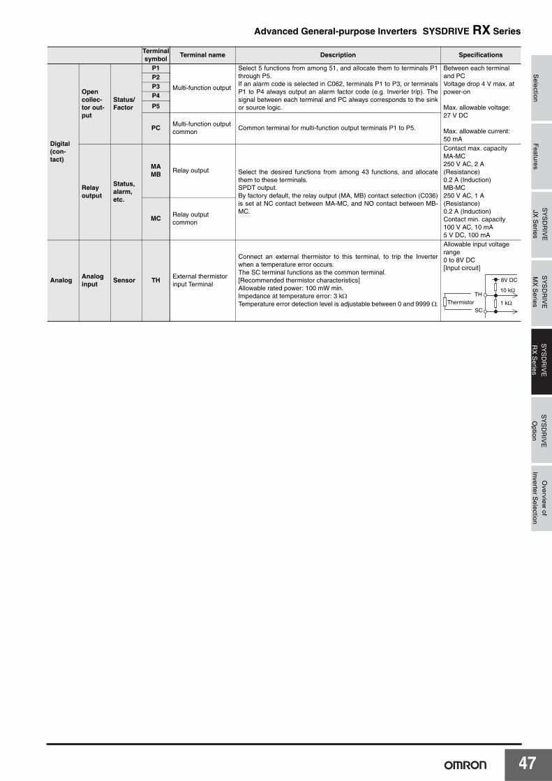
Selection
Features
SY
SD
RIV
EJX
Series
SY
SD
RIV
EM
X S
eriesS
YS
DR
IVE
RX
Series
SY
SD
RIV
EO
ption
Overview
ofInverter S
election
Advanced General-purpose Inverters SYSDRIVE RX Series
Digital (con-tact)
Open collec-tor out-put
Status/ Factor
P1
Multi-function output
Select 5 functions from among 51, and allocate them to terminals P1through P5.If an alarm code is selected in C062, terminals P1 to P3, or terminalsP1 to P4 always output an alarm factor code (e.g. Inverter trip). Thesignal between each terminal and PC always corresponds to the sinkor source logic.
Between each terminal and PCVoltage drop 4 V max. at power-on
Max. allowable voltage: 27 V DC
Max. allowable current: 50 mA
P2P3P4
P5
PCMulti-function output common
Common terminal for multi-function output terminals P1 to P5.
Relay output
Status, alarm, etc.
MAMB
Relay output Select the desired functions from among 43 functions, and allocatethem to these terminals.SPDT output.By factory default, the relay output (MA, MB) contact selection (C036)is set at NC contact between MA-MC, and NO contact between MB-MC.
Contact max. capacityMA-MC250 V AC, 2 A (Resistance)0.2 A (Induction)MB-MC250 V AC, 1 A (Resistance)0.2 A (Induction)Contact min. capacity100 V AC, 10 mA5 V DC, 100 mA
MCRelay output common
AnalogAnalog input
Sensor THExternal thermistor input Terminal
Connect an external thermistor to this terminal, to trip the Inverterwhen a temperature error occurs.The SC terminal functions as the common terminal.[Recommended thermistor characteristics]Allowable rated power: 100 mW min.Impedance at temperature error: 3 kΩTemperature error detection level is adjustable between 0 and 9999 Ω.
Allowable input voltage range0 to 8V DC[Input circuit]
Terminal symbol
Terminal name Description Specifications
TH
SC
Thermistor
8V DC
10 kΩ
1 kΩ
47
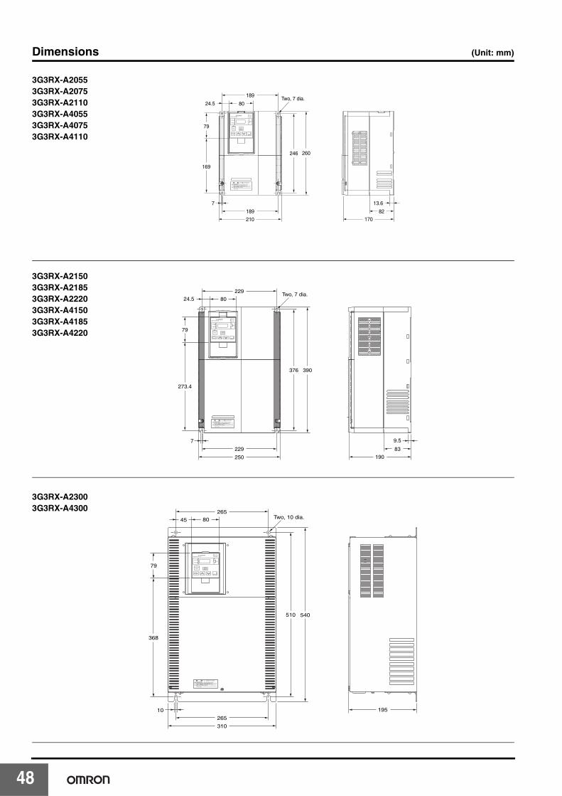
4
Dimensions (Unit: mm)
169
79
246 260
210
24.5 80Two, 7 dia.
189
189
82
13.6
170
7
3G3RX-A20553G3RX-A20753G3RX-A21103G3RX-A40553G3RX-A40753G3RX-A4110
79
273.4
229
229
9.5
83
376 390
250 190
24.5 80Two, 7 dia.
7
3G3RX-A21503G3RX-A21853G3RX-A22203G3RX-A41503G3RX-A41853G3RX-A4220
265
265
310
10
368
79
510 540
45
195
Two, 10 dia.80
3G3RX-A23003G3RX-A4300
8
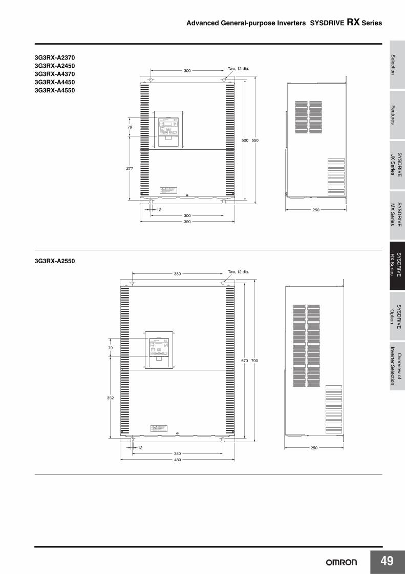
Selection
Features
SY
SD
RIV
EJX
Series
SY
SD
RIV
EM
X S
eriesS
YS
DR
IVE
RX
Series
SY
SD
RIV
EO
ption
Overview
ofInverter S
election
Advanced General-purpose Inverters SYSDRIVE RX Series
390
12
300
300
520 550
250
Two, 12 dia.
79
277
3G3RX-A23703G3RX-A24503G3RX-A43703G3RX-A44503G3RX-A4550
380
380
670 700
12
480
250
79
352
Two, 12 dia.
3G3RX-A2550
49
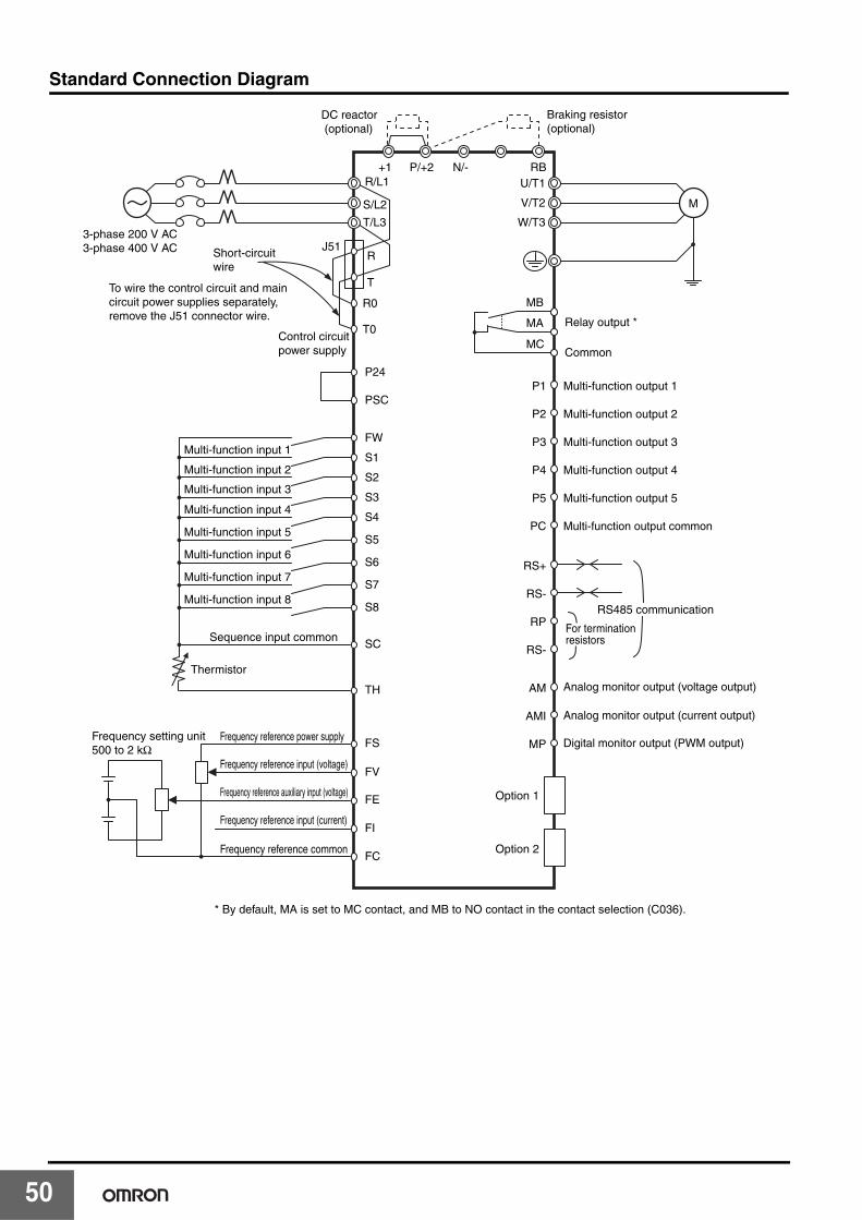
5
Standard Connection Diagram
DC reactor (optional)
3-phase 200 V AC3-phase 400 V AC
Multi-function input 1
Multi-function input 2
Multi-function input 3
Multi-function input 4
Multi-function input 5
Multi-function input 6
Multi-function input 7
Multi-function input 8
Frequency reference power supplyFrequency setting unit500 to 2 kΩ
Frequency reference input (voltage)
Frequency reference auxiliary input (voltage)
Frequency reference input (current)
Frequency reference common
* By default, MA is set to MC contact, and MB to NO contact in the contact selection (C036).
Sequence input common
M
R/L1+1 P/+2
Braking resistor (optional)
RBN/-
T/L3
R
T
R0
T0
S/L2
U/T1
W/T3
P2 Multi-function output 2
P3 Multi-function output 3
P4 Multi-function output 4
P5 Multi-function output 5
PC
RS+
RS-
RP
RS-
AM
AMI
MP
Option 1
Option 2
Multi-function output common
Analog monitor output (voltage output)
Analog monitor output (current output)
Digital monitor output (PWM output)
P1 Multi-function output 1
Relay output *
Common
V/T2
S1
FW
P24
PSC
S4
SC
Thermistor
TH
FS
FI
FC
FV
FE
S3
S2
S5
RS485 communication
S6
S7
S8
Short-circuit wire
To wire the control circuit and main circuit power supplies separately, remove the J51 connector wire.
Control circuit power supply
J51
For termination resistors
MB
MA
MC
0

Selection
Features
SY
SD
RIV
EJX
Series
SY
SD
RIV
EM
X S
eriesS
YS
DR
IVE
RX
Series
SY
SD
RIV
EO
ption
Overview
ofInverter S
election
Advanced General-purpose Inverters SYSDRIVE RX Series
Protective and Diagnostic Functions●Error Code List
Display on Digital Operator
Name Description
Overcurrent protection
Constantspeed If the motor is restrained or rapidly accelerated or decelerated, a large current will flow through
the Inverter, which will result in breakage. The larger than specified current then shuts off theoutput and an error appears.The protection detects this overcurrent through AC CT (current detector).The protection circuit operates at approximately 220% of the Inverter rated output current anda trip occurs.
Deceleration
Acceleration
Others
Overload protection *1Monitors the Inverter output current and shuts off the output, displaying an error if the built-in electronicthermal function detects overload against the motor.Trips depending on the electronic thermal function settings.
Braking resistor overload protection
Shuts off the output and displays an error if the usage rate of regenerative braking circuit exceeds the b090set value.
Overvoltage protection
Extremely high DC voltage between P/+2 and N/- may result in failure. This function therefore shuts off theoutput and displays an error if the DC voltage between P/+2 and N/- exceeds the specified level because ofregenerative energy from the motor or increase of the incoming voltage during operation.Trips when the DC voltage between P/+2 and N/- reaches approximately 400 V DC for 200-V class, and 800V DC for 400-V class.
EEPROM error *2 *3
Shuts off the output and displays an error if an error occurs because of external noise and abnormaltemperature rise in the EEPROM built into the Inverter.Note: It may become a CPU error depending on the case.
Undervoltage
Shuts off the output if the incoming voltage drops below that specified. This is because the control circuit failsto work properly, if the incoming voltage to the Inverter drops.Trips when the DC voltage between P and N reaches approximately 175 V DC for 200-V class, and 345 V DCfor 400-V class.
CT errorShuts off the output if an error occurs in the CT (current detector) built into the Inverter. Trips if the CT outputis approximately 0.6 V or more when the power is turned on.
CPU error *3Shuts off the output and displays an error if the internal CPU has worked erroneously or abnormally.Note: If an abnormal value is read from EEPROM, it may become a CPU error depending on the case.
External tripIf an error occurs in the external equipment or devices, the Inverter receives the signal, and the output is shutoff. (Available with the external trip function selected)
USP errorAppears when the power is turned on with the RUN signal input into the Inverter.(Available with the USP function selected)
Grounding protection *3Protects the Inverter if a ground fault between the Inverter output unit and the motor is detected when turningon the power. (This function does not work when there is residual voltage in the motor.)
Incoming overvoltage protection
Appears if the incoming voltage continues to be higher than the specification value for 100 seconds while theInverter is stopped.Trips when the main circuit DC voltage reaches approximately 390 V DC for 200-V class, and 780 V DC for400-V class.
Momentary power interruption protection
Shuts off the output when a momentary power interruption occurs for 15 ms or more.If the shutoff time is long, it is normally recognized as a power shutoff. Note that, when restart is selected, theInverter restarts from recovery as long as the RUN command remains.
Temperature error when the rotation speed of the cooling fan decreases
Appears if a decrease of the cooling fan rotation speed has been detected when the following temperatureerror occurs.
Temperature error Shuts off the output if the temperature has risen in the main circuit because of the high ambient temperature.
Gate array communications error
Trips when a fault is detected in communication behavior between the built-in CPU and the gate array.
Input open-phase protection
Prevents Inverter damage due to input open-phase protection function when the input open-phase selectionis enabled (b006=01), and trips.Trips when the open-phase time is approximately 1 s or more.
Main circuit error *3Trips when the gate array cannot confirm IGBT ON/OFF because of erroneous operation or main elementbreakage caused by noise interfusion.
IGBT errorShuts off the Inverter output to protect the main element when a momentary overcurrent, temperature error inthe main element, or drop of the main element driving power supply occurs.(Retry operation cannot be performed after this trip.)
Thermistor errorShuts off the Inverter output when detecting the thermistor resistance value inside the motor connected tothe TH terminal and resulting motor temperature rise.
Brake errorWhen 01 is selected in b120 (brake control selection), this error appears if the brake ON/OFF cannot berecognized within the b124 set time (brake confirmation wait time) after the Inverter outputs the brake releasesignal.
Emergency shutoff *4Shuts off the hardware output and displays an error when the EMR terminal (S3) is turned on with SW1 onthe logic board ON.
Overload protection in a low speed range
If an overload is detected in the lowest speed range of 0.2 Hz max., an electronic thermal inside the Inverterworks to shut off the Inverter output. (2nd electronic thermal level)(However, higher frequency could remain in the error history.)
Modbus communications error
Appears when the timeout occurs because of disconnection during Modbus-RTU communication.(Trip by the C076 setting)
ek0k1.
ek0k2.
ek0k3.
ek0k4.
ek0k5.
ek0k6.
ek0k7.
ek0k8.
ek0k9.
ek1k0.
ek1k1.
ek1k2.
ek1k3.
ek1k4.
ek1k5.
ek1k6.
ek2k0.
ek2k1.
ek2k3.
ek2k4.
ek2k5.
ek3k0.
ek3k5.
ek3k6.
ek3k7.
ek3k8.
ek4k1.
51

5
*1. The reset command will not be accepted until approximately 10 seconds pass since the trip occurs (protection function works)
*2. The reset command will not be accepted if the EEPROM error occurs. Turn off the power once. If you find E08 when turning on the power again, it ispossible that the memory element has been broken or the parameters have not been memorized correctly. Perform the user initialization to set the parametersagain.
*3. The reset command through the RS terminal or STOP/RESET key will not be accepted. Turn off the power.*4. The reset operation via the Digital Operator will not be accepted. Be sure to reset via the RS terminal.
Option 1 errorDetects an error on the board mounted on option slot 1. For details, refer to the operation manual for themounted option board.
Option 2 errorDetects an error on the board mounted on option slot 2. For details, refer to the operation manual for themounted option board.
Display on Digital Operator
Name Description
ek6k0.
ek6k9.
ek7k0.
ek7k9.
ek0k8.
2
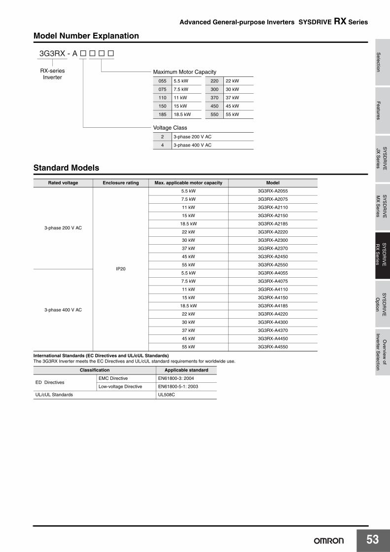
Selection
Features
SY
SD
RIV
EJX
Series
SY
SD
RIV
EM
X S
eriesS
YS
DR
IVE
RX
Series
SY
SD
RIV
EO
ption
Overview
ofInverter S
election
Advanced General-purpose Inverters SYSDRIVE RX Series
Model Number Explanation
Standard Models
International Standards (EC Directives and UL/cUL Standards)The 3G3RX Inverter meets the EC Directives and UL/cUL standard requirements for worldwide use.
Rated voltage Enclosure rating Max. applicable motor capacity Model
3-phase 200 V AC
IP20
5.5 kW 3G3RX-A2055
7.5 kW 3G3RX-A2075
11 kW 3G3RX-A2110
15 kW 3G3RX-A2150
18.5 kW 3G3RX-A2185
22 kW 3G3RX-A2220
30 kW 3G3RX-A2300
37 kW 3G3RX-A2370
45 kW 3G3RX-A2450
55 kW 3G3RX-A2550
3-phase 400 V AC
5.5 kW 3G3RX-A4055
7.5 kW 3G3RX-A4075
11 kW 3G3RX-A4110
15 kW 3G3RX-A4150
18.5 kW 3G3RX-A4185
22 kW 3G3RX-A4220
30 kW 3G3RX-A4300
37 kW 3G3RX-A4370
45 kW 3G3RX-A4450
55 kW 3G3RX-A4550
Classification Applicable standard
ED DirectivesEMC Directive EN61800-3: 2004
Low-voltage Directive EN61800-5-1: 2003
UL/cUL Standards UL508C
Maximum Motor Capacity
Voltage Class
RX-seriesInverter
055
075
110
5.5 kW
7.5 kW
11 kW
220
300
22 kW
30 kW
150 15 kW 450 45 kW
185 18.5 kW 550 55 kW
370 37 kW
2
4
3-phase 200 V AC
3-phase 400 V AC
3G3RX - A � � � �
53
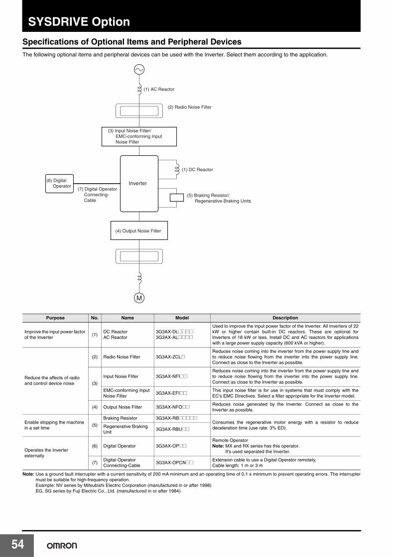
54
SYSDRIVE Option
Specifications of Optional Items and Peripheral DevicesThe following optional items and peripheral devices can be used with the Inverter. Select them according to the application.
Note: Use a ground fault interrupter with a current sensitivity of 200 mA minimum and an operating time of 0.1 s minimum to prevent operating errors. The interruptermust be suitable for high-frequency operation. Example: NV series by Mitsubishi Electric Corporation (manufactured in or after 1998)EG, SG series by Fuji Electric Co., Ltd. (manufactured in or after 1984)
Purpose No. Name Model Description
Improve the input power factor of the Inverter
(1)DC ReactorAC Reactor
3G3AX-DL@@@@3G3AX-AL@@@@
Used to improve the input power factor of the Inverter. All Inverters of 22kW or higher contain built-in DC reactors. These are optional forInverters of 18 kW or less. Install DC and AC reactors for applicationswith a large power supply capacity (600 kVA or higher).
Reduce the affects of radio and control device noise
(2) Radio Noise Filter 3G3AX-ZCL@Reduces noise coming into the inverter from the power supply line andto reduce noise flowing from the inverter into the power supply line.Connect as close to the Inverter as possible.
(3)
Input Noise Filter 3G3AX-NFI@@Reduces noise coming into the inverter from the power supply line andto reduce noise flowing from the inverter into the power supply line.Connect as close to the Inverter as possible.
EMC-conforming Input Noise Filter
3G3AX-EFI@@ This input noise filter is for use in systems that must comply with theEC's EMC Directives. Select a filter appropriate for the Inverter model.
(4) Output Noise Filter 3G3AX-NFO@@ Reduces noise generated by the Inverter. Connect as close to theInverter as possible.
Enable stopping the machine in a set time
(5)
Braking Resistor 3G3AX-RB@@@@@Consumes the regenerative motor energy with a resistor to reducedeceleration time (use rate: 3% ED).Regenerative Braking
Unit3G3AX-RBU@@
Operates the Inverter externally
(6) Digital Operator 3G3AX-OP@@Remote OperatorNote: MX and RX series has this operator.
It's used separated the Inverter.
(7)Digital Operator Connecting-Cable
3G3AX-OPCN@@ Extension cable to use a Digital Operator remotely.Cable length: 1 m or 3 m
M
(1) AC Reactor
(2) Radio Noise Filter
(1) DC Reactor
Inverter
(3) Input Noise Filter/ EMC-conforming Input Noise Filter
(4) Output Noise Filter
(5) Braking Resistor/ Regenerative Braking Units
(6) Digital Operator
(7) Digital Operator Connecting- Cable

SYSDRIVE OptionS
electionF
eaturesS
YS
DR
IVE
JX S
eries
SY
SD
RIV
EM
X S
eriesS
YS
DR
IVE
RX
Series
SY
SD
RIV
EO
ptionO
verview of
Inverter Selection
JX/MX/RX Series Related Options ❍: Release
* The braking resistor is optionally required.
Name Model SpecificationsApplicable Series
JX MX RX
Regenerative Braking Units
3G3AX-RBU21
3-phase 200 V
General purpose with Braking resistor ❍ ❍ ❍
3G3AX-RBU22 High Regeneration purpose with Braking resistor ❍ ❍ ❍
3G3AX-RBU23 General purpose for 30 kW * ❍
3G3AX-RBU24 General purpose for 55 kW * ❍
3G3AX-RBU41
3-phase 400 V
General purpose with Braking resistor ❍ ❍ ❍
3G3AX-RBU42 General purpose for 30 kW * ❍
3G3AX-RBU43 General purpose for 55 kW * ❍
Braking Resistor
3G3AX-RBA1201
Compact type
Resistor 120 W, 180 Ω ❍ ❍
3G3AX-RBA1202 Resistor 120 W, 100 Ω ❍ ❍
3G3AX-RBA1203 Resistor 120 W, 5 Ω ❍ ❍
3G3AX-RBA1204 Resistor 120 W, 35 Ω ❍ ❍
3G3AX-RBB2001
Standard type
Resistor 200 W, 180 Ω ❍ ❍
3G3AX-RBB2002 Resistor 200 W, 100 Ω ❍ ❍
3G3AX-RBB3001 Resistor 300 W, 50 Ω ❍ ❍
3G3AX-RBB4001 Resistor 400 W, 35 Ω ❍ ❍
3G3AX-RBC4001Medium capacity type
Resistor 400 W, 50 Ω ❍
3G3AX-RBC6001 Resistor 600 W, 35 Ω ❍
3G3AX-RBC12001 Resistor 1200 W, 17 Ω ❍
DC Reactor
3G3AX-DL2002
3-phase 200 V
0.2 kW ❍ ❍ ❍
3G3AX-DL2004 0.4 kW ❍ ❍ ❍
3G3AX-DL2007 0.7 kW ❍ ❍ ❍
3G3AX-DL2015 1.5 kW ❍ ❍ ❍
3G3AX-DL2022 2.2 kW ❍ ❍ ❍
3G3AX-DL2037 3.7 kW ❍ ❍ ❍
3G3AX-DL2055 5.5 kW ❍ ❍ ❍
3G3AX-DL2075 7.5 kW ❍ ❍ ❍
3G3AX-DL2110 11 kW ❍
3G3AX-DL2150 15 kW ❍
3G3AX-DL2220 22 kW ❍
3G3AX-DL2300 30 kW ❍
3G3AX-DL2370 37 kW ❍
3G3AX-DL2450 45 kW ❍
3G3AX-DL2550 55 kW ❍
3G3AX-DL4004
3-phase 400 V
0.4 kW ❍ ❍ ❍
3G3AX-DL4007 0.7 kW ❍ ❍ ❍
3G3AX-DL4015 1.5 kW ❍ ❍ ❍
3G3AX-DL4022 2.2 kW ❍ ❍ ❍
3G3AX-DL4037 3.7 kW ❍ ❍ ❍
3G3AX-DL4055 5.5 kW ❍ ❍ ❍
3G3AX-DL4075 7.5 kW ❍ ❍ ❍
3G3AX-DL4110 11 kW ❍
3G3AX-DL4150 15 kW ❍
3G3AX-DL4220 22 kW ❍
3G3AX-DL4300 30 kW ❍
3G3AX-DL4370 37 kW ❍
3G3AX-DL4450 45 kW ❍
3G3AX-DL4550 55 kW ❍
Radio Noise Filter3G3AX-ZCL1 ❍ ❍ ❍
3G3AX-ZCL2 ❍ ❍ ❍
55
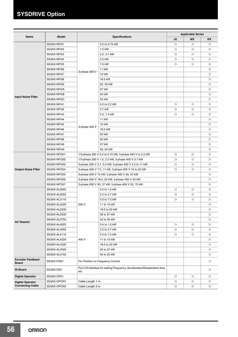
SYSDRIVE Option
5
Name Model SpecificationsApplicable Series
JX MX RX
Input Noise Filter
3G3AX-NFI21
3-phase 200 V
0.2 to 0.75 kW ❍ ❍ ❍
3G3AX-NFI22 1.5 kW ❍ ❍ ❍
3G3AX-NFI23 2.2, 3.7 kW ❍ ❍ ❍
3G3AX-NFI24 5.5 kW ❍ ❍ ❍
3G3AX-NFI25 7.5 kW ❍ ❍ ❍
3G3AX-NFI26 11 kW ❍
3G3AX-NFI27 15 kW ❍
3G3AX-NFI28 18.5 kW ❍
3G3AX-NFI29 22, 30 kW ❍
3G3AX-NFI2A 37 kW ❍
3G3AX-NFI2B 45 kW ❍
3G3AX-NFI2C 55 kW ❍
3G3AX-NFI41
3-phase 400 V
0.2 to 2.2 kW ❍ ❍ ❍
3G3AX-NFI42 3.7 kW ❍ ❍ ❍
3G3AX-NFI43 5.5, 7.5 kW ❍ ❍ ❍
3G3AX-NFI44 11 kW ❍
3G3AX-NFI45 15 kW ❍
3G3AX-NFI46 18.5 kW ❍
3G3AX-NFI47 22 kW ❍
3G3AX-NFI48 30 kW ❍
3G3AX-NFI49 37 kW ❍
3G3AX-NFI4A 45, 55 kW ❍
Output Noise Filter
3G3AX-NFO01 1/3-phase 200 V 0.2 to 0.75 kW, 3-phase 400 V to 2.2 kW ❍ ❍ ❍
3G3AX-NFO02 1/3-phase 200 V 1.5, 2.2 kW, 3-phase 400 V 3.7 kW ❍ ❍ ❍
3G3AX-NFO03 3-phase 200 V 3.7, 5.5 kW, 3-phase 400 V 5.5 to 11 kW ❍ ❍ ❍
3G3AX-NFO04 3-phase 200 V 7.5, 11 kW, 3-phase 400 V 15 to 22 kW ❍ ❍ ❍
3G3AX-NFO05 3-phase 200 V 15 kW, 3-phase 400 V 30, 37 kW ❍
3G3AX-NFO06 3-phase 200 V 18.5, 22 kW, 3-phase 400 V 45 kW ❍
3G3AX-NFO07 3-phase 200 V 30, 37 kW, 3-phase 400 V 55, 75 kW ❍
AC Reactor
3G3AX-AL2025
200 V
0.2 to 1.5 kW ❍ ❍ ❍
3G3AX-AL2055 2.2 to 3.7 kW ❍ ❍ ❍
3G3AX-AL2110 5.5 to 7.5 kW ❍ ❍ ❍
3G3AX-AL2220 11 to 15 kW ❍
3G3AX-AL2330 18.5 to 22 kW ❍
3G3AX-AL2500 30 to 37 kW ❍
3G3AX-AL2750 45 to 55 kW ❍
3G3AX-AL4025
400 V
0.4 to 1.5 kW ❍ ❍ ❍
3G3AX-AL4055 2.2 to 3.7 kW ❍ ❍ ❍
3G3AX-AL4110 5.5 to 7.5 kW ❍ ❍ ❍
3G3AX-AL4220 11 to 15 kW ❍
3G3AX-AL4330 18.5 to 22 kW ❍
3G3AX-AL4500 30 to 37 kW ❍
3G3AX-AL4750 45 to 55 kW ❍
Encoder Feedback Board
3G3AX-PG01 For Position or Frequency Control ❍
DI Board 3G3AX-DI01PLC I/O Interface for setting Frequency, Acceleration/Deceleration time etc
❍
Digital Operator 3G3AX-OP01 ❍ ❍ ❍
Digital Operator Connecting Cable
3G3AX-OPCN1 Cable Length 1 m ❍ ❍ ❍
3G3AX-OPCN3 Cable Length 3 m ❍ ❍ ❍
6

SYSDRIVE Option
MEMO
57
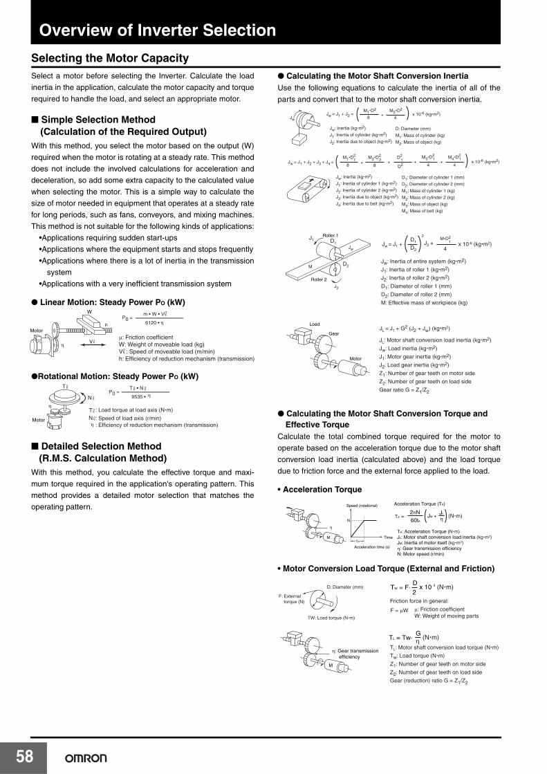
58
Overview of Inverter Selection
Selecting the Motor CapacitySelect a motor before selecting the Inverter. Calculate the load
inertia in the application, calculate the motor capacity and torque
required to handle the load, and select an appropriate motor.
■ Simple Selection Method (Calculation of the Required Output)
With this method, you select the motor based on the output (W)
required when the motor is rotating at a steady rate. This method
does not include the involved calculations for acceleration and
deceleration, so add some extra capacity to the calculated value
when selecting the motor. This is a simple way to calculate the
size of motor needed in equipment that operates at a steady rate
for long periods, such as fans, conveyors, and mixing machines.
This method is not suitable for the following kinds of applications:
•Applications requiring sudden start-ups
•Applications where the equipment starts and stops frequently
•Applications where there is a lot of inertia in the transmission
system
•Applications with a very inefficient transmission system
● Linear Motion: Steady Power PO (kW)
●Rotational Motion: Steady Power PO (kW)
■ Detailed Selection Method (R.M.S. Calculation Method)
With this method, you calculate the effective torque and maxi-
mum torque required in the application's operating pattern. This
method provides a detailed motor selection that matches the
operating pattern.
● Calculating the Motor Shaft Conversion InertiaUse the following equations to calculate the inertia of all of the
parts and convert that to the motor shaft conversion inertia.
● Calculating the Motor Shaft Conversion Torque and Effective Torque
Calculate the total combined torque required for the motor to
operate based on the acceleration torque due to the motor shaft
conversion load inertia (calculated above) and the load torque
due to friction force and the external force applied to the load.
• Acceleration Torque
• Motor Conversion Load Torque (External and Friction)
Motor
W
V
μ
μ: Friction coefficientW: Weight of moveable load (kg)V : Speed of moveable load (m/min)h: Efficiency of reduction mechanism (transmission)
m • W • V
6120 • η
η
P0 =
Motor
T • N
9535 • ηN
T
ηTNη
: Load torque at load axis (N�m)
: Speed of load axis (r/min): Efficiency of reduction mechanism (transmission)
P0 =
Jw
D: Diameter (mm)
M1: Mass of cylinder (kg)
M2: Mass of object (kg)
Jw: Inertia (kg�m2)
J1: Inertia of cylinder (kg�m2)
J2: Inertia due to object (kg�m2)
Jw = J1 + J2 = M1�D
2
8+
M2�D2
4x 10⁻⁶ (kg�m2)
Jw = J1 + J2 + J3 + J4 = M1�D
2
8+
M2�D2
8x 10⁻⁶ (kg�m2)1 2 +
D2
D21 +
M3�D2
41
+M4�D
2
41
D1: Diameter of cylinder 1 (mm)
D2: Diameter of cylinder 2 (mm)
M1: Mass of cylinder 1 (kg)
M2: Mass of cylinder 2 (kg)
M3: Mass of object (kg)
M4: Mass of belt (kg)
Jw: Inertia (kg�m2)
J1: Inertia of cylinder 1 (kg�m2)
J2: Inertia of cylinder 2 (kg�m2)
J3: Inertia due to object (kg�m2)
J4: Inertia due to belt (kg�m2)
Roller 1
Roller 2
Load
Gear
Motor
Jw = J1 + D1
D2
2
J2 + M�D2
1
4x 10⁻⁶ (kg�m2)
Jw: Inertia of entire system (kg�m2)
J1: Inertia of roller 1 (kg�m2)
J2: Inertia of roller 2 (kg�m2)
D1: Diameter of roller 1 (mm)
D2: Diameter of roller 2 (mm)
M: Effective mass of workpiece (kg)
J1 D1
D2
J2
Jw
M
JL = J1 + G2 (J2 + Jw) (kg�m2)
JL: Motor shaft conversion load inertia (kg�m2)
Jw: Load inertia (kg�m2)
J1: Motor gear inertia (kg�m2)
J2: Load gear inertia (kg�m2)
Z1: Number of gear teeth on motor side
Z2: Number of gear teeth on load side
Gear ratio G = Z1/Z2
A
TA =
Acceleration Torque (TA)
N
Acceleration time (s)
Speed (rotational)
Timet
M
η
2πN
60tA
JM + JL
η (N�m)
TA: Acceleration Torque (N�m)JL: Motor shaft conversion load inertia (kg�m2)JM: Inertia of motor itself (kg�m2)η: Gear transmission efficiencyN: Motor speed (r/min)
2
DD: Diameter (mm)
TW: Load torque (N�m)
F: External torque (N)
TW = F� x 10−3 (N�m)
Friction force in general:
F = μW μ: Friction coefficientW: Weight of moving parts
M
η: Gear transmission efficiency
TL: Motor shaft conversion load torque (N�m)
Tw: Load torque (N�m)
Z1: Number of gear teeth on motor side
Z2: Number of gear teeth on load side
Gear (reduction) ratio G = Z1/Z2
ηG
TL = Tw� (N�m)
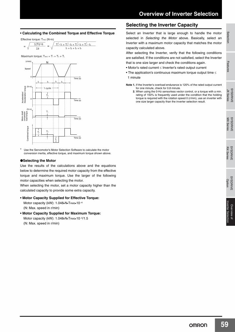
Overview of Inverter SelectionS
electionF
eaturesS
YS
DR
IVE
JX S
eriesS
YS
DR
IVE
MX
Series
SY
SD
RIV
ER
X S
eriesS
YS
DR
IVE
Option
Overview
ofInverter S
election
• Calculating the Combined Torque and Effective Torque
* Use the Servomotor's Motor Selection Software to calculate the motorconversion inertia, effective torque, and maximum torque shown above.
●Selecting the MotorUse the results of the calculations above and the equations
below to determine the required motor capacity from the effective
torque and maximum torque. Use the larger of the following
motor capacities when selecting the motor.
When selecting the motor, set a motor capacity higher than the
calculated capacity to provide some extra capacity.
• Motor Capacity Supplied for Effective Torque:Motor capacity (kW): 1.048•N•TRMS•10−4
(N: Max. speed in r/min)
• Motor Capacity Supplied for Maximum Torque:Motor capacity (kW): 1.048•N•TRMS•10−4/1.5
(N: Max. speed in r/min)
Selecting the Inverter Capacity
Select an Inverter that is large enough to handle the motor
selected in Selecting the Motor above. Basically, select an
Inverter with a maximum motor capacity that matches the motor
capacity calculated above.
After selecting the Inverter, verify that the following conditions
are satisfied. If the conditions are not satisfied, select the Inverter
that is one size larger and check the conditions again.
• Motor’s rated current ≤ Inverter’s rated output current
• The application’s continuous maximum torque output time ≤1 minute
Note 1. If the Inverter's overload endurance is 120% of the rated output currentfor one minute, check for 0.8 minute.
2. When using the 0-Hz sensorless vector control, or a torque with a min.rating of 150% is frequently used under the condition that the holdingtorque is required with the rotation speed 0 (r/min), use an inverter withone size larger capacity than the inverter selection result.
(N�m)
(N�m)
Time (s)0
0Time (s)
Time (s)
Time (s)
N
=
Speed
(r/min)
Acc
eler
atio
n/D
ecel
erat
ion
torq
ueM
otor
sha
ft co
nver
sion
load
torq
ue
Com
bine
d to
rque
T3
T2T1
TL
TA
1 cycle
t1 t2 t3 t4
Maximum torque: TMAX = T1 = TA + TL
Effective torque: TRMS (N�m)
Σ(Ti)2�ti
Σti=
t1 + t2 + t3 + t4
T1 � t1 + T2 � t2 + T3 � t3 + T4 � t42 2 22
59
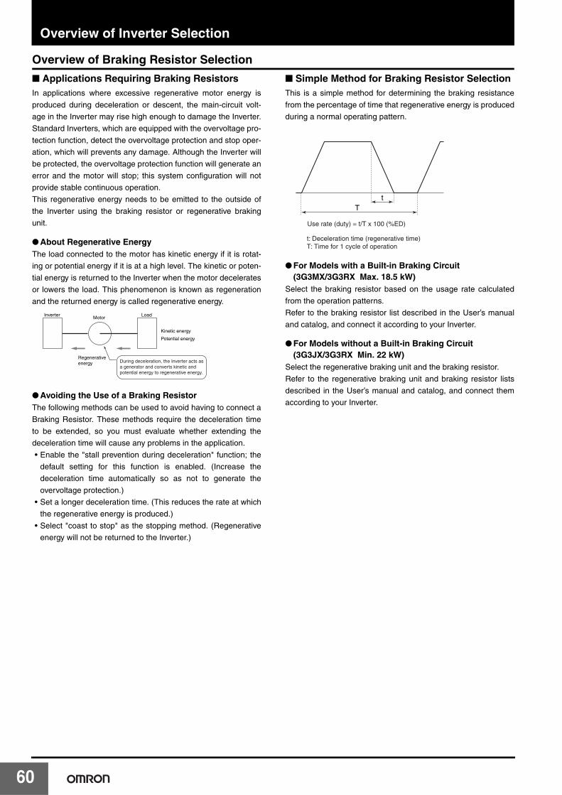
Overview of Inverter Selection
6
Overview of Braking Resistor Selection
■ Applications Requiring Braking ResistorsIn applications where excessive regenerative motor energy is
produced during deceleration or descent, the main-circuit volt-
age in the Inverter may rise high enough to damage the Inverter.
Standard Inverters, which are equipped with the overvoltage pro-
tection function, detect the overvoltage protection and stop oper-
ation, which will prevents any damage. Although the Inverter will
be protected, the overvoltage protection function will generate an
error and the motor will stop; this system configuration will not
provide stable continuous operation.
This regenerative energy needs to be emitted to the outside of
the Inverter using the braking resistor or regenerative braking
unit.
● About Regenerative EnergyThe load connected to the motor has kinetic energy if it is rotat-
ing or potential energy if it is at a high level. The kinetic or poten-
tial energy is returned to the Inverter when the motor decelerates
or lowers the load. This phenomenon is known as regeneration
and the returned energy is called regenerative energy.
● Avoiding the Use of a Braking ResistorThe following methods can be used to avoid having to connect a
Braking Resistor. These methods require the deceleration time
to be extended, so you must evaluate whether extending the
deceleration time will cause any problems in the application.
• Enable the "stall prevention during deceleration" function; the
default setting for this function is enabled. (Increase the
deceleration time automatically so as not to generate the
overvoltage protection.)
• Set a longer deceleration time. (This reduces the rate at which
the regenerative energy is produced.)
• Select "coast to stop" as the stopping method. (Regenerative
energy will not be returned to the Inverter.)
■ Simple Method for Braking Resistor SelectionThis is a simple method for determining the braking resistance
from the percentage of time that regenerative energy is produced
during a normal operating pattern.
● For Models with a Built-in Braking Circuit (3G3MX/3G3RX Max. 18.5 kW)
Select the braking resistor based on the usage rate calculated
from the operation patterns.
Refer to the braking resistor list described in the User’s manual
and catalog, and connect it according to your Inverter.
● For Models without a Built-in Braking Circuit (3G3JX/3G3RX Min. 22 kW)
Select the regenerative braking unit and the braking resistor.
Refer to the regenerative braking unit and braking resistor lists
described in the User’s manual and catalog, and connect them
according to your Inverter.
Inverter Load
Regenerativeenergy
Kinetic energy
Potential energy
Motor
During deceleration, the Inverter acts as a generator and converts kinetic and potential energy to regenerative energy.
Tt
Use rate (duty) = t/T x 100 (%ED)
t: Deceleration time (regenerative time)T: Time for 1 cycle of operation
0
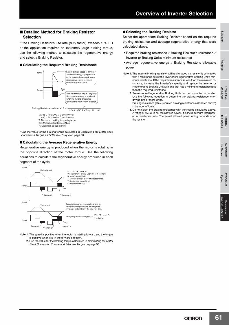
Overview of Inverter SelectionS
electionF
eaturesS
YS
DR
IVE
JX S
eriesS
YS
DR
IVE
MX
Series
SY
SD
RIV
ER
X S
eriesS
YS
DR
IVE
Option
Overview
ofInverter S
election
■ Detailed Method for Braking Resistor Selection
If the Braking Resistor's use rate (duty factor) exceeds 10% ED
or the application requires an extremely large braking torque,
use the following method to calculate the regenerative energy
and select a Braking Resistor.
● Calculating the Required Braking Resistance
* Use the value for the braking torque calculated in Calculating the Motor ShaftConversion Torque and Effective Torque on page 58.
● Calculating the Average Regenerative EnergyRegenerative energy is produced when the motor is rotating in
the opposite direction of the motor torque. Use the following
equations to calculate the regenerative energy produced in each
segment of the cycle.
Note 1. The speed is positive when the motor is rotating forward and the torqueis positive when it is in the forward direction.
2. Use the value for the braking torque calculated in Calculating the MotorShaft Conversion Torque and Effective Torque on page 58.
● Selecting the Braking ResistorSelect the appropriate Braking Resistor based on the required
braking resistance and average regenerative energy that were
calculated above.
• Required braking resistance ≥ Braking Resistor's resistance ≥Inverter or Braking Unit's minimum resistance
• Average regenerative energy ≤ Braking Resistor's allowable
power
Note 1. The internal braking transistor will be damaged if a resistor is connectedwith a resistance below the Inverter or Regenerative Braking Unit's min-imum resistance. If the required resistance is less than the minimum re-sistance, increase the Inverter's capacity and replace the Inverter orRegenerative Braking Unit with one that has a minimum resistance lessthan the required resistance.
2. Two or more Regenerative Braking Units can be connected in parallel.Use the following equation to determine the braking resistance whendriving two or more Units.Braking resistance (Ω) = (required braking resistance calculated above)× (number of Units)
3. Do not select the braking resistance with the results calculated above.A rating of 150 W is not the allowed power, it is the maximum rated pow-er in resistance units. The actual allowed power rating depends uponthe resistor.
Energy at max. speed N (r/min):The kinetic energy is proportionalto the square of the speed, so the regenerative energy is highest momentarily at this point.
Max deceleration torque T (kgf•cm):Regenerative energy is produced when the motor's direction is opposite the motor torque direction.
TimeTorque
Speed
Braking Resistor’s resistance: R ≤V2
1.048 x (T-0.2 x Tm) x N x 10-1
V: 385 V for a 200-V Class Inverter 400 V for a 400-V Class InverterT: Maximum braking torque (kgf•cm)Tm: Motor’s rated torque (N•cm)N: Maximum speed (r/min)
Segment 1 Segment 2
Horizontal load
Vertical load
Torque
Torque
Speed
Speed
Time
Segment 1Segment 2
Segment 3
Time
Pi: N x T x t x 1.048 x 10⁻¹
Pi: Regenerative energy (J) produced in segmentiN: Motor’s speed (r/min) (Use the average speed if the speed varies.)T: Deceleration torque (N•m)t: Deceleration time (s)
Calculate the average regenerative energy by adding the power produced in each segment of the cycle and dividing by the total cycle time.
Average regenerative energy (W) = (P1 + P2 + ...... + P)
1 cycle time
61

MEMO
62
Read and Understand this Catalog
Please read and understand this catalog before purchasing the product. Please consult your OMRON representative if you have any questions or comments.
Warranty and Limitations of Liability
WARRANTY
OMRON's exclusive warranty is that the products are free from defects in materials and workmanship for a period of one year (or other period if specified) from date of sale by OMRON.
OMRON MAKES NO WARRANTY OR REPRESENTATION, EXPRESS OR IMPLIED, REGARDING NON-INFRINGEMENT, MERCHANTABILITY, OR FITNESS FOR PARTICULAR PURPOSE OF THE PRODUCTS. ANY BUYER OR USER ACKNOWLEDGES THAT THE BUYER OR USER ALONE HAS DETERMINED THAT THE PRODUCTS WILL SUITABLY MEET THE REQUIREMENTS OF THEIR INTENDED USE. OMRON DISCLAIMS ALL OTHER WARRANTIES, EXPRESS OR IMPLIED.
LIMITATIONS OF LIABILITY
OMRON SHALL NOT BE RESPONSIBLE FOR SPECIAL, INDIRECT, OR CONSEQUENTIAL DAMAGES, LOSS OF PROFITS, OR COMMERCIAL LOSS IN ANY WAY CONNECTED WITH THE PRODUCTS, WHETHER SUCH CLAIM IS BASED ON CONTRACT, WARRANTY, NEGLIGENCE, OR STRICT LIABILITY.
In no event shall the responsibility of OMRON for any act exceed the individual price of the product on which liability is asserted.
IN NO EVENT SHALL OMRON BE RESPONSIBLE FOR WARRANTY, REPAIR, OR OTHER CLAIMS REGARDING THE PRODUCTS UNLESS OMRON'S ANALYSIS CONFIRMS THAT THE PRODUCTS WERE PROPERLY HANDLED, STORED, INSTALLED, AND MAINTAINED AND NOT SUBJECT TO CONTAMINATION, ABUSE, MISUSE, OR INAPPROPRIATE MODIFICATION OR REPAIR.
Application Considerations
SUITABILITY FOR USE
OMRON shall not be responsible for conformity with any standards, codes, or regulations that apply to the combination of products in the customer's application or use of the products.
Take all necessary steps to determine the suitability of the product for the systems, machines, and equipment with which it will be used.
Know and observe all prohibitions of use applicable to this product.
NEVER USE THE PRODUCTS FOR AN APPLICATION INVOLVING SERIOUS RISK TO LIFE OR PROPERTY WITHOUT ENSURING THAT THE SYSTEM AS A WHOLE HAS BEEN DESIGNED TO ADDRESS THE RISKS, AND THAT THE OMRON PRODUCTS ARE PROPERLY RATED AND INSTALLED FOR THE INTENDED USE WITHIN THE OVERALL EQUIPMENT OR SYSTEM.
PROGRAMMABLE PRODUCTS
OMRON shall not be responsible for the user’s programming of a programmable product, or any consequence thereof.
Disclaimers
CHANGE IN SPECIFICATIONS
Product specifications and accessories may be changed at any time based on improvements and other reasons.
It is our practice to change model numbers when published ratings or features are changed, or when significant construction changes are made. However, some specifications of the products may be changed without any notice. When in doubt, special model numbers may be assigned to fix or establish key specifications for your application on your request. Please consult with your OMRON representative at any time to confirm actual specifications of purchased products.
DIMENSIONS AND WEIGHTS
Dimensions and weights are nominal and are not to be used for manufacturing purposes, even when tolerances are shown.
PERFORMANCE DATA
Performance data given in this catalog is provided as a guide for the user in determining suitability and does not constitute a warranty. It may represent the result of OMRON’s test conditions, and the users must correlate it to actual application requirements. Actual performance is subject to the OMRON Warranty and Limitations of Liability.

Authorized Distributor:
© OMRON Corporation 2008 All Rights Reserved.In the interest of product improvement, specifications are subject to change without notice.
Note: Do not use this document to operate the Unit.
Printed in Japan0508 (0208)
OMRON CorporationIndustrial Automation Company
Control Devices Division H.Q.
Motion Control Department
Shiokoji Horikawa, Shimogyo-ku,Kyoto, 600-8530 JapanTel: (81) 75-344-7173/Fax: (81) 75-344-7149
2-2-1 Nishikusatsu, Kusatsu-shi,Shiga, 525-0035 JapanTel: (81) 77-565-5223/Fax: (81) 77-565-5568
Regional Headquarters
OMRON EUROPE B.V.
Wegalaan 67-69, NL-2132 JD HoofddorpThe NetherlandsTel: (31)2356-81-300/Fax: (31)2356-81-388
OMRON ELECTRONICS LLC
One Commerce Drive Schaumburg,IL 60173-5302 U.S.A.Tel: (1) 847-843-7900/Fax: (1) 847-843-7787
OMRON ASIA PACIFIC PTE. LTD.
No. 438A Alexandra Road # 05-05/08 (Lobby 2),Alexandra Technopark, Singapore 119967Tel: (65) 6835-3011/Fax: (65) 6835-2711
OMRON (CHINA) CO., LTD.
Room 2211, Bank of China Tower,200 Yin Cheng Zhong Road,Pu Dong New Area, Shanghai, 200120, ChinaTel: (86) 21-5037-2222/Fax: (86) 21-5037-2200
Cat. No. I914-E1-02OMRON Industrial Automation Global:www.ia.omron.com