Embed Size (px)
Citation preview
Environmental Mine Waste Management:Strategies for the Prevention, Control, and Treatment
of Problematic DrainagesVolume 1 of 2
Advances in Mine Waste Management ProjectFinal Report to the Minerals Coordinating Committee
June 30, 2001
Minnesota Department of Natural ResourcesDivision of Lands and Minerals

ENVIRONMENTAL MINE WASTE MANAGEMENT:
STRATEGIES FOR THE PREVENTION, CONTROL, AND
TREATMENT OF PROBLEMATIC DRAINAGES
Volume 1 of 2
Advances in Mine Waste Management ProjectReport to the Minerals Coordinating Committee
June 30, 2001
Emmelyn LeopoldKim Lapakko
Minnesota Department of Natural ResourcesDivision of Lands and Minerals
500 Lafayette RoadSaint Paul, MN 55155

Environmental Mine Waste Management StrategiesOrganizational Scheme
PreventionStrategies
ControlStrategies
TreatmentStrategies
SelectiveHandling
BackfillingMine Voids
Co-disposal:Tailings & Waste
Rock
PhysicalIsolation
"Dry" Covers
"Wet" Covers
BiologicalStabilization
Bactericides
ChemicalStabilization
AlkalineAmendments
Microencapsulation
PassiveSystems
ConstructedWetlands
PermeableReactive Barriers
ActiveSystems
Acid Neutralization
ChemicalPrecipitation
Ion Exchange
Membrane Filtration
BiologicalSulfate Reduction
EXECUTIVE SUMMARY
Considerable mineral potential for base and precious metals is associated with Minnesota’sPrecambrian rocks, specifically in Archean metavolcanics, metasedimentary formations, and theDuluth Complex. If mineral development occurs, the potential for generation of acidic minewaste drainage is the primary water quality concern. The goal of this document is to evaluatecurrent methods and identify strategies for environmental mine waste management that showpotential for application in Minnesota.
A search of literature contained in the Minnesota Department of Natural Resources, Division ofLands and Minerals literature database and various mine waste management conferenceproceedings resulted in a large number of citations. Consequently, it was necessary to refine thescope of this document. This was accomplished by reviewing similar efforts in Canada,Australia, the United States, and Sweden to compile information on the current state ofenvironmental mine waste management technology.
As a result of the literature search and scope refinement, fifteen environmental mine wastemanagement strategies were identified for further investigation. In order to create an organizedand efficient presentation, the fifteen strategies were divided into three generalized categories:prevention, control, and treatment. The first category deals with strategies intended to preventthe generation of problematic drainages. Strategies that control problematic drainage in situ areconsidered in the second category. Finally, existing problematic drainages generally requiretreatment, the third category. Within this context, the fifteen target strategies are arranged asfollows:
Selected literature regarding these fifteen environmental mine waste management strategies willbe reviewed in terms of: 1) a brief description; 2) methods used to assess performance; 3)generalized cost analysis; and 4) applicability to environmental mine waste management issuesin Minnesota. When available, case studies are included in the appropriate appendix. It isimportant to note that this review does not represent a comprehensive literature review on theprevention, control, or treatment of acid mine drainage, nor does it address the entire range ofpossible preventive technologies currently in use.
As a result of this literature review, it was determined that there is no single, correct approachto environmental mine waste management. Successful mine waste management and mitigationprograms implement multiple strategies to address a wide array of site- and waste-specificvariables. Integrated management systems, including contingencies to treat impacted waters,are often necessary to meet regulatory standards. Four examples of integrated environmentalmine waste management approaches used in Minnesota, Wisconsin, and South Dakota arepresented.
TABLE OF CONTENTS
INTRODUCTION
1. Mining in Minnesota . . . . . . . . . . . . . . . . . . . . . . . . . . . . . . . . . . . . . . . . . . . . . . . . . . 11.1. Mine Waste Drainage Mitigation in Minnesota . . . . . . . . . . . . . . . . . . . . . . . 1
1.1.1. MN DNR laboratory and small-scale field studies . . . . . . . . . . . . . . . 21.1.2. MN DNR operational-scale field studies . . . . . . . . . . . . . . . . . . . . . . . 3
1.2. Objectives and Scope . . . . . . . . . . . . . . . . . . . . . . . . . . . . . . . . . . . . . . . . . . . . 31.2.1 United States . . . . . . . . . . . . . . . . . . . . . . . . . . . . . . . . . . . . . . . . . . . . 41.2.2 Canada . . . . . . . . . . . . . . . . . . . . . . . . . . . . . . . . . . . . . . . . . . . . . . . . . 51.2.3 Australia . . . . . . . . . . . . . . . . . . . . . . . . . . . . . . . . . . . . . . . . . . . . . . . . 51.2.4 Sweden . . . . . . . . . . . . . . . . . . . . . . . . . . . . . . . . . . . . . . . . . . . . . . . . . 61.2.5 International . . . . . . . . . . . . . . . . . . . . . . . . . . . . . . . . . . . . . . . . . . . . . 6
1.3 Structure of this Document . . . . . . . . . . . . . . . . . . . . . . . . . . . . . . . . . . . . . . . 71.4. References . . . . . . . . . . . . . . . . . . . . . . . . . . . . . . . . . . . . . . . . . . . . . . . . . . . . 9
2. Geochemical Background . . . . . . . . . . . . . . . . . . . . . . . . . . . . . . . . . . . . . . . . . . . . . 142.1. Mine Waste Dissolution and Acid Mine Drainage . . . . . . . . . . . . . . . . . . . . 142.2. References . . . . . . . . . . . . . . . . . . . . . . . . . . . . . . . . . . . . . . . . . . . . . . . . . . . 15
PREVENTION STRATEGIES
3. Selective Handling of Reactive Mine Wastes . . . . . . . . . . . . . . . . . . . . . . . . . . . . . . 173.1. Backfilling Reactive Mine Wastes . . . . . . . . . . . . . . . . . . . . . . . . . . . . . . . . 17
3.1.1. Objectives of Backfilling Reactive Mine Wastes . . . . . . . . . . . . . . . 173.1.2. Monitoring Water Quality Associated with Backfilled Mine Works
. . . . . . . . . . . . . . . . . . . . . . . . . . . . . . . . . . . . . . . . . . . . . . . . . . . . . . 183.1.3. Economic Benefits of Backfilling Mine Voids . . . . . . . . . . . . . . . . . 193.1.4. Potential Application of Backfill Technology in Minnesota . . . . . . . 19
3.2. Co-disposal of Tailings and Waste Rock as a Preventative Strategy . . . . . . 193.2.1. Objectives of Co-disposal . . . . . . . . . . . . . . . . . . . . . . . . . . . . . . . . . 193.2.2. Evaluation of Co-disposal Performance . . . . . . . . . . . . . . . . . . . . . . 203.2.3. Economic Benefits of Co-disposal of Mine Wastes . . . . . . . . . . . . . 223.2.4. Co-disposal Studies and Applications in Minnesota . . . . . . . . . . . . . 23
3.2.4.1. MN DNR Joint Disposal Studies3.2.4.2. Minnesota Mineral Research Center Studies Involving
Co-disposal3.2.4.3. Full-Scale Application of Co-disposal in a Taconite
Tailings Basin3.3. References for Selective Handling of Reactive Mine Wastes . . . . . . . . . . . . 27
4. Physical Isolation of Reactive Mine Wastes . . . . . . . . . . . . . . . . . . . . . . . . . . . . . . . 33
4.1. Liners . . . . . . . . . . . . . . . . . . . . . . . . . . . . . . . . . . . . . . . . . . . . . . . . . . . . . . . 334.2. Dry Cover Systems . . . . . . . . . . . . . . . . . . . . . . . . . . . . . . . . . . . . . . . . . . . . 34
4.2.1. Objectives of a Dry Cover System . . . . . . . . . . . . . . . . . . . . . . . . . . . 344.2.2. Dry Cover System Designs . . . . . . . . . . . . . . . . . . . . . . . . . . . . . . . . 364.2.3 Assessment of Dry Cover System Designs . . . . . . . . . . . . . . . . . . . . 39
4.2.3.1. Variables Affecting Dry Cover System Design4.2.3.2. Predictive Modeling of Dry Cover System Design4.2.3.3. Materials Testing4.2.3.4. Effectiveness of a Dry Cover System Design
4.2.4. Cost Analysis of Dry Cover Systems . . . . . . . . . . . . . . . . . . . . . . . . . 404.2.5. Potential for the Use of Dry Cover Systems for Reactive Mine Wastes in
Minnesota . . . . . . . . . . . . . . . . . . . . . . . . . . . . . . . . . . . . . . . . . . . . . . 414.2.5.1. Dry Cover Systems Used in Minnesota4.2.5.2. Potential for Capillary Barriers4.2.5.3. Potential for Organic Cover Systems
4.3. Water Cover Systems . . . . . . . . . . . . . . . . . . . . . . . . . . . . . . . . . . . . . . . . . . . 434.3.1. Principles of Water Cover Systems . . . . . . . . . . . . . . . . . . . . . . . . . . 434.3.2. Water Cover System Designs . . . . . . . . . . . . . . . . . . . . . . . . . . . . . . 444.3.3. Assessment of Water Cover Systems . . . . . . . . . . . . . . . . . . . . . . . . 45
4.3.3.1. Variables Affecting the Design of a Water Cover System4.3.3.2. Modeling Water Cover Systems4.3.3.3. Effectiveness of a Water Cover System
4.3.4. Cost Analysis of Water Cover Systems . . . . . . . . . . . . . . . . . . . . . . . 474.3.5. Water Cover Studies and Potential Use in Minnesota . . . . . . . . . . . . 47
4.3.5.1. MN DNR Subaqueous Disposal Studies4.3.5.2. MN DNR Study to Create Wetlands on Reactive Tailings4.3.5.3. Potential Use of Water Covers in Minnesota
4.4. References on Physical Isolation of Reactive Mine Wastes . . . . . . . . . . . . . 49
CONTROL STRATEGIES
5. Chemical Stabilization of Reactive Mine Wastes . . . . . . . . . . . . . . . . . . . . . . . . . . . 575.1. Alkaline Amendments . . . . . . . . . . . . . . . . . . . . . . . . . . . . . . . . . . . . . . . . . . 57
5.1.1. The Goals of Alkaline Amendments . . . . . . . . . . . . . . . . . . . . . . . . . 575.1.2. Assessment of Alkaline Amendment Effectiveness . . . . . . . . . . . . . 585.1.3. Cost Analysis of Adding Alkaline Materials to Reactive Mine
Wastes . . . . . . . . . . . . . . . . . . . . . . . . . . . . . . . . . . . . . . . . . . . . . . . . 585.1.4. Alkaline Amendments and Reactive Mine Wastes in Minnesota . . . 59
5.2. Microencapsulation of Reactive Wastes . . . . . . . . . . . . . . . . . . . . . . . . . . . . 605.2.1. Mechanisms of Microencapsulation . . . . . . . . . . . . . . . . . . . . . . . . . 605.2.2. Assessment of Microencapsulation Effectiveness . . . . . . . . . . . . . . . 615.2.3. Cost Analysis of Microencapsulation Techniques . . . . . . . . . . . . . . . 615.2.4. Potential Use of Microencapsulation Technology to Address Mine Waste
Issues in Minnesota . . . . . . . . . . . . . . . . . . . . . . . . . . . . . . . . . . . . . . 635.3. Organic Amendments . . . . . . . . . . . . . . . . . . . . . . . . . . . . . . . . . . . . . . . . . . 63
5.4. References on the Chemical Stabilization of Reactive Mine Wastes . . . . . . 64
6. Biological Stabilization of Reactive Mine Wastes . . . . . . . . . . . . . . . . . . . . . . . . . . 686.1. Inhibition of Biological Sulfide Oxidation Using Bactericides . . . . . . . . . . . 686.2. Assessment of Bactericides as Sulfide Oxidation Inhibitors . . . . . . . . . . . . . 68
6.2.1. Preliminary Evaluation of Bactericides . . . . . . . . . . . . . . . . . . . . . . . 686.2.2. Parameters Used to Assess Bactericide Effectiveness . . . . . . . . . . . . 69
6.3. Cost Analysis of Bactericides . . . . . . . . . . . . . . . . . . . . . . . . . . . . . . . . . . . . 696.4. Potential Use of Bactericides to Inhibit Sulfide Oxidation in Minnesota Mine
Wastes . . . . . . . . . . . . . . . . . . . . . . . . . . . . . . . . . . . . . . . . . . . . . . . . . . . . . . 696.5. References on the Use of Bactericides . . . . . . . . . . . . . . . . . . . . . . . . . . . . . 71
TREATMENT SYSTEMS
7. Passive Treatment Systems . . . . . . . . . . . . . . . . . . . . . . . . . . . . . . . . . . . . . . . . . . . . 747.1. Constructed Wetlands . . . . . . . . . . . . . . . . . . . . . . . . . . . . . . . . . . . . . . . . . . 75
7.1.1. Aerobic Wetlands . . . . . . . . . . . . . . . . . . . . . . . . . . . . . . . . . . . . . . . . 757.1.2. Organic Substrate Wetlands . . . . . . . . . . . . . . . . . . . . . . . . . . . . . . . . 757.1.3. Assessment of Constructed Wetland Treatment System Designs and
Size . . . . . . . . . . . . . . . . . . . . . . . . . . . . . . . . . . . . . . . . . . . . . . . . . . . 767.1.4. Cost Analysis of Constructed Wetland Treatment Systems . . . . . . . 777.1.5. Constructed Wetland Treatment of Problematic Drainages in
Minnesota . . . . . . . . . . . . . . . . . . . . . . . . . . . . . . . . . . . . . . . . . . . . . . 787.2. Permeable Reactive Barriers . . . . . . . . . . . . . . . . . . . . . . . . . . . . . . . . . . . . . 80
7.2.1. Factors Affecting Permeable Reactive Barrier Performance . . . . . . . 817.2.2. Evaluation of Reactive Barrier Systems . . . . . . . . . . . . . . . . . . . . . . 837.2.3. Construction Costs Associated with Reactive Barriers . . . . . . . . . . . 837.2.4. Potential Application of Reactive Barrier Technology in
Minnesota . . . . . . . . . . . . . . . . . . . . . . . . . . . . . . . . . . . . . . . . . . . . . . 837.3. Passive Treatment References . . . . . . . . . . . . . . . . . . . . . . . . . . . . . . . . . . . . 85
8. Active Treatment Systems . . . . . . . . . . . . . . . . . . . . . . . . . . . . . . . . . . . . . . . . . . . . . 958.1 Acid Neutralization Treatment Systems . . . . . . . . . . . . . . . . . . . . . . . . . . . . 958.2. Chemical Precipitation Systems . . . . . . . . . . . . . . . . . . . . . . . . . . . . . . . . . . 988.3. Ion Exchange Technology . . . . . . . . . . . . . . . . . . . . . . . . . . . . . . . . . . . . . . . 99
8.3.1. The GYP-CIX Process . . . . . . . . . . . . . . . . . . . . . . . . . . . . . . . . . . . . 998.3.2. BIO-FIX Beads . . . . . . . . . . . . . . . . . . . . . . . . . . . . . . . . . . . . . . . . 1008.3.3. Zeolites and Selective Chelating Resins . . . . . . . . . . . . . . . . . . . . . 100
8.4. Membrane Filtration . . . . . . . . . . . . . . . . . . . . . . . . . . . . . . . . . . . . . . . . . . 1028.5. Biological Sulfate Reduction Treatment Systems . . . . . . . . . . . . . . . . . . . . 1038.6. Assessment of Active Treatment Systems . . . . . . . . . . . . . . . . . . . . . . . . . . 1058.7. Cost Comparison of Different Active Treatment Systems . . . . . . . . . . . . . 1068.8. Application of Active Treatment Systems to Problematic Mine Drainages in
Minnesota . . . . . . . . . . . . . . . . . . . . . . . . . . . . . . . . . . . . . . . . . . . . . . . . . . . 1088.8.1. AMAX/Kennecott Test Site . . . . . . . . . . . . . . . . . . . . . . . . . . . . . . . 108
8.8.2. MN DNR Field Research Site, Hibbing, MN . . . . . . . . . . . . . . . . . 1108.8.3. Dunka Mine Site . . . . . . . . . . . . . . . . . . . . . . . . . . . . . . . . . . . . . . . 110
8.9. Active Treatment References . . . . . . . . . . . . . . . . . . . . . . . . . . . . . . . . . . . . 113
SUMMARY AND CONCLUSIONS
9. Integrated Case Studies . . . . . . . . . . . . . . . . . . . . . . . . . . . . . . . . . . . . . . . . . . . . . . 1189.1. Dunka Mine, Babbitt, Minnesota . . . . . . . . . . . . . . . . . . . . . . . . . . . . . . . . . 1189.2. Flambeau Mine, near Ladysmith, Wisconsin . . . . . . . . . . . . . . . . . . . . . . . 120
9.2.1. Mine Waste Characterization and Storage . . . . . . . . . . . . . . . . . . . . 1209.2.2. Backfill Operation . . . . . . . . . . . . . . . . . . . . . . . . . . . . . . . . . . . . . . 1229.2.3. Environmental and Ground Water Monitoring . . . . . . . . . . . . . . . . 123
9.3. Richmond Hill Gold Mine, South Dakota . . . . . . . . . . . . . . . . . . . . . . . . . . 1249.3.1. Short-term Mitigation Measures . . . . . . . . . . . . . . . . . . . . . . . . . . . 1259.3.2. Closure Plans . . . . . . . . . . . . . . . . . . . . . . . . . . . . . . . . . . . . . . . . . . 1259.3.3. Environmental and Ground Water Monitoring . . . . . . . . . . . . . . . . 126
9.4. Crandon Deposit (Proposed Mine), Crandon, Wisconsin . . . . . . . . . . . . . . 1279.5. References . . . . . . . . . . . . . . . . . . . . . . . . . . . . . . . . . . . . . . . . . . . . . . . . . . 128
LIST OF FIGURES
Figure 1. Environmental mine waste management strategies addressed in this document . . . . . . . . . . . . . . . . . . . . . . . . . . . . . . . . . . . . . . . . . . . . . . . . . . . . . 8
Figure 2. Schematic of a generalized dry cover system design . . . . . . . . . . . . . . . . . . 35Figure 3. Dry cover designs generally fall into one of seven categories . . . . . . . . . . . 38Figure 4. Constructed wetland design depends upon the chemistry of water to be
treated . . . . . . . . . . . . . . . . . . . . . . . . . . . . . . . . . . . . . . . . . . . . . . . . . . . . . . . 76Figure 5. Cross-sectional view of a permeable reactive wall . . . . . . . . . . . . . . . . . . . . 80Figure 6. Drainage from field experiments conducted at the MN DNR Hibbing research
facility is treated with magnesium hydroxide . . . . . . . . . . . . . . . . . . . . . . . 111Figure 7. Area map of the Dunka Mine, near Babbitt, MN . . . . . . . . . . . . . . . . . . . . 119Figure 8. Aerial view of the Flambeau pit seen from the northeast . . . . . . . . . . . . . . 121Figure 9. Schematic diagram of the Richmond Hill Mine complex, near Lead, South
Dakota . . . . . . . . . . . . . . . . . . . . . . . . . . . . . . . . . . . . . . . . . . . . . . . . . . . . . 124
LIST OF TABLES
Table 1. Several practical waste handling design and transportation issues must be
addressed when considering a co-disposal strategy . . . . . . . . . . . . . . . . . . . . 21Table 2. Costs associated with co-disposal of tailings and waste rock . . . . . . . . . . . . 22Table 3. Flow-weighted concentrations from joint disposal bins . . . . . . . . . . . . . . . . 24Table 4. Calcite-bearing taconite tailings reduced the amount of nickel and copper release
from Duluth Complex ore . . . . . . . . . . . . . . . . . . . . . . . . . . . . . . . . . . . . . . . 24Table 5. Water chemistry measured from monitoring wells and seeps in LTV Steel
Mining Company’s tailings basin . . . . . . . . . . . . . . . . . . . . . . . . . . . . . . . . . 25Table 6. Summary of water chemistry measured from a seep on the southwest side of LTV
Steel Mining Company’s tailings basin . . . . . . . . . . . . . . . . . . . . . . . . . . . . . 26Table 7. Summary of cover construction costs by type of cover . . . . . . . . . . . . . . . . . 40Table 8. Oxygen solubility/concentration and diffusion coefficient in air and water at
25EC . . . . . . . . . . . . . . . . . . . . . . . . . . . . . . . . . . . . . . . . . . . . . . . . . . . . . . . . 43Table 9. A wide array of factors should be assessed prior to disposing of reactive waste
rock beneath a water cover . . . . . . . . . . . . . . . . . . . . . . . . . . . . . . . . . . . . . . 46Table 10. Natural geologic, industrial, and waste products have been used as alkaline
amendments . . . . . . . . . . . . . . . . . . . . . . . . . . . . . . . . . . . . . . . . . . . . . . . . . . 57Table 11. Prices for alkaline materials vary widely . . . . . . . . . . . . . . . . . . . . . . . . . . . . 59Table 12. Summary of drainage quality results from microencapsulation laboratory tests
and field demonstrations . . . . . . . . . . . . . . . . . . . . . . . . . . . . . . . . . . . . . . . . 62Table 13. Summary of results from laboratory studies designed to evaluate the
effectiveness of bacterial inhibitors . . . . . . . . . . . . . . . . . . . . . . . . . . . . . . . . 70Table 14. Summary of results from field tests on the effect of bacterial inhibitors . . . 70Table 15. Summary of naturally occurring removal mechanisms . . . . . . . . . . . . . . . . . 74Table 16. Summary of major cost components for constructed wetlands . . . . . . . . . . . 77Table 17. Five wetland treatment systems located at the Dunka Mine site near Babbitt, MN
have treated near-neutral drainage from stockpiles with variable results . . . 79Table 18. The long-term success of permeable reactive barriers have not been
established . . . . . . . . . . . . . . . . . . . . . . . . . . . . . . . . . . . . . . . . . . . . . . . . . . . 85Table 19. Summary of the advantages and disadvantages of some common neutralization
chemicals . . . . . . . . . . . . . . . . . . . . . . . . . . . . . . . . . . . . . . . . . . . . . . . . . . . . 96Table 20. Summary of the sludge dewatering methods used in coal mining . . . . . . . . . 97Table 21. The GYP-CIX process resulted in elevated pH and decreased levels of Ca, Mg,
Fe, Mn, Cu, Zn, and SO4 in waters from the Berkeley Pit, Butte, MT . . . . 101Table 22. Two different treatment approaches have been used to demonstrate metal
removal by BIO-FIX beads in four field-scale tests . . . . . . . . . . . . . . . . . . 101Table 23. Summary of membrane filtration techniques . . . . . . . . . . . . . . . . . . . . . . . 102Table 24. Optimum drainage chemistry for various active treatment systems . . . . . . 105Table 25. Average operational costs of selected North American acid neutralization
treatment operations . . . . . . . . . . . . . . . . . . . . . . . . . . . . . . . . . . . . . . . . . . . 107Table 26. Several active treatment system requirements increase operating costs . . . 107Table 27. Qualitative cost analysis information indicate that ion exchange and reverse
osmosis are the most expensive active treatment options . . . . . . . . . . . . . . 109Table 28. MN DNR Hibbing research site treatment plant specifications. . . . . . . . . . 112Table 29. Leachate treatment specifications for the MN DNR research site treatment
plant . . . . . . . . . . . . . . . . . . . . . . . . . . . . . . . . . . . . . . . . . . . . . . . . . . . . . . . 112Table 30. Summary of environmental mine waste management activities and research
projects at the Dunka Mine, Babbitt, MN . . . . . . . . . . . . . . . . . . . . . . . . . . 118Table 31. Physical characteristics of the Flambeau open mine pit and operation . . . . 120Table 32. Overburden and waste rock were classified based on sulfur content and placed
in separate surface storage facilities during operation of the Flambeau Mine . . . . . . . . . . . . . . . . . . . . . . . . . . . . . . . . . . . . . . . . . . . . . . . . . . . . . . . 122
APPENDICES
APPENDIX 1: Mitigation and Treatment References (In progress)APPENDIX 2: Selective Handling of Reactive Mine WastesAPPENDIX 3: Physical Isolation of Reactive Mine WastesAPPENDIX 4: Chemical Stabilization of Reactive Mine Waste MaterialsAPPENDIX 5: Biological Stabilization of Reactive Mine Wastes (Bactericides)APPENDIX 6: Treatment Systems for Problematic DrainageAPPENDIX 7: Integrated Case Studies
ACKNOWLEDGMENTS
Funding for this project was provided by the Minerals Coordinating Committee from theMinerals Diversification Program of the Minnesota Legislature. Char Fiest obtained much ofthe literature reviewed in this document. Her contribution was invaluable. Additional peoplewho provided information related to the development of this compilation include: DaveAntonson (MN DNR), Jon Bennett (ANSTO), David Blowes (U of Waterloo), Angus Campbell(CO Dept. of Health), Richard Clark (MN PCA), Paul Eger (MN DNR), Bill Evangelou (IowaState U), James Gusek (Knight Piesold & CO), Mike Holm (EPA), Victor Ketalapper (EPA),Larry Lynch (WI DNR), Mark Nelson (SD DENR), Bill Price (BC Ministry of Energy andMines), Dan Scheppers (CO Dept. of Health), Mary Scott (CO Dept. of Health), Giles Tremblay(CANMET), and Jon Wagner (MN DNR). Special thanks to Dave Antonson (MN DNR),Daniel Doctor (MN DNR), Jennifer Engstrom (MN DNR), Larry Lynch (WI DNR), MarkNelson (SD DENR), Erin Phillips (MN DNR), and Jon Wagner (MN DNR) for reviewing andcommenting on sections of this document.
1
INTRODUCTION
1. Mining in Minnesota
Minnesota has an extensive mining industry and potential for mineral expansion anddiversification. Iron mining began in Minnesota over a century ago and led to the taconitemining industry which, in 1996, shipped 45 million long tons of iron ore valued at 2.4 billiondollars (Minnesota Department of Revenue, 1997). Nonferrous mining development showspromise for the future. The state is presently the subject of extensive mineral exploration, with59 leases covering more than 26,000 acres of state land (MN DNR, 1998).
Considerable base and precious metal mineral potential is associated with Minnesota’sPrecambrian rocks, specifically in Archean metavolcanics, metasedimentary formations and theDuluth Complex. The Archean metavolcanics and metasedimentary formations, or greenstonebelts, of Minnesota extend north into Canada, where they have yielded substantial mineralproduction. These formations are potential hosts for gold, zinc-copper massive sulfides withvarious by-products, and magmatic sulfide deposits containing copper, nickel, and platinumgroup elements. Recent exploration of greenstone belt metasedimentary formations has focusedon gold, base metals, and silver-cobalt-copper deposits. The Duluth Complex contains anestimated copper-nickel resource of 4.4 billion tons (Minnesota Environmental Quality Board,1979), as well as significant titanium resources. Drill core analyses have also revealed thepresence of chromium, vanadium, cobalt, and platinum group elements.
If mineral development occurs, tailings and waste rock, as well as the mine itself will be wastesremaining after the operation is abandoned. The potential for generation of acidic mine wastedrainage is the primary water quality concern, and this potential is largely determined by themine waste composition. Mine wastes capable of producing problematic drainage must bemanaged to ensure that the quality of Minnesota waters is not adversely impacted. Mine wastemanagement strategies directed at this objective include prevention, control, and treatment ofproblematic drainage. However, implementation of mitigative strategies alone is not sufficientinsurance of non problematic drainage. Empirical data on the long-term performance of mostmine waste management strategies is limited. Consequently, surface and ground watermonitoring must also be included in any environmental mine waste management plan.
1.1. Mine Waste Drainage Mitigation in Minnesota
The Reclamation Section within the Division of Lands and Minerals, Minnesota Department ofNatural Resources (MN DNR) has conducted numerous studies on environmental mine wastemanagement (Lapakko et al., 1998a). Mitigative laboratory and small-scale field studies includethe use of alkaline solids and subaqueous disposal of sulfidic waste rock. Operational-scalemitigative measures include capping and selective placement of reactive waste rock, drainagediversion, and passive and active treatment systems.
2
In addition to these studies, disposal of taconite tailings within existing open mine pits andassociated surface and ground water quality have been investigated (Berndt et al., 1999;Lapakko and Jakel, 1999). However, taconite tailings contain very little sulfidic material andsufficient carbonate minerals to prevent acidic drainage in waters associated with them. Thus,these studies are beyond the scope of this presentation and will not be mentioned here.
1.1.1. MN DNR laboratory and small-scale field studies
A two-phase, laboratory and field program examined the feasibility of removing trace metals(Cu, Ni, Co, Zn) from stockpile drainage using readily available materials (peat, till, wood chips,Cu-Ni tailings, and zeolite) in low-cost, low-maintenance systems at the AMAX/Kennecott site.The results of the entire program are presented in two reports (Lapakko et al., 1986a,b), andsynopses of various research segments are presented in several symposium proceedings(Lapakko and Eger 1981, 1983, 1988; Lapakko et al, 1983; Eger et al., 1984).
Laboratory experiments were conducted to examine the mitigative potential of mixing alkalinesolids with acid-producing mine waste. In one of these laboratory experiments, rotary kiln fines(RK fines; a waste product generated by the conversion of limestone to lime), !10 meshlimestone, and +10 mesh/-0.25 inch limestone were each mixed with finely crushed DuluthComplex rock (0.053 < d # 0.149 mm) to examine their effectiveness in reducing the release ofacid and trace metals in drainage from the rock (Lapakko and Antonson, 1989a, 1990a, 1991;Lapakko et al., 1997, 2000).
Laboratory and small-scale field tests were conducted to determine the effectiveness oflimestone beds for treating mine waste drainage. In the laboratory, columns containing +10mesh/ -0.25 inch high calcium limestone were used to treat three problematic mine drainages,one from a stockpile at the Dunka mine site and two from field test piles at theAMAX/Kennecott site (Lapakko and Antonson, 1989b, 1990a,b). Based on the results from thelaboratory study, a field-scale limestone bed (1.4 m3 bed volume) was constructed to treat oneof the problematic drainages at the Dunka site (Lapakko and Antonson, 1989c, 1990c).
Finally, disposal of sulfidic rock in a subaqueous setting with and without various layers toinhibit oxygen transport (unmodified subaqueous, composted yard waste, taconite tailings,compost and taconite tailings, and limestone) is under investigation in laboratory experiments.Taconite tailings, tailings and compost, and limestone barriers are also being examined in fieldexperiments (MN DNR, unpublished data).
Although these laboratory and small-scale field tests show promise as mitigative techniques forreactive mine wastes in Minnesota, it is important to note that, at this time, none of them havebeen tested at an operational-scale. Furthermore, each of these tests was conducted on a singlerock type. Consequently, conclusions related to the application of these techniques to specific,large-scale, environmental mine waste problems in Minnesota should be regarded cautiously.
1.1.2. MN DNR operational-scale field studies
3
Operational-scale field studies of passive wetland and active treatment systems have beenimplemented at the Dunka mine site. Based on the observation that metals were removed fromwaste rock stockpile drainage as it flowed through a white cedar swamp (Eger et al., 1980; Egerand Lapakko, 1988), studies were conducted to evaluate the use of wetlands as a technique formitigating mine waste drainage. Literature was reviewed to summarize reported mechanismsand capacities for metal removal by peat (as well as other materials, Lapakko et al., 1985, 1986a,b) and laboratory experiments were conducted with native peat and waste rock drainage to moreaccurately assess the reactions applicable to situations in Minnesota (Lapakko and Eger, 1983).These results were subsequently used to estimate metal removal by peat under field conditionsin Minnesota (Lapakko and Eger, 1988).
Based on the laboratory results, as well as observed metal removal by peat in a white cedarswamp and other natural wetlands, field test plots were designed (Eger and Lapakko, 1989) andmetal removal in these systems was quantified (Eger et al., 1994). Based partly on these studies,wetland treatment systems were designed to treat drainage from operational-scale stockpiles(Eger et al., 1996, 1997, 2000). In addition to the wetland treatment system, the stockpiles werecovered with various dry cover systems to reduce flow to these treatment systems (STSConsultants Ltd., 1993, 1994a, 1994b). An active lime precipitation treatment plant treatsdrainage from several of the aforementioned systems.
Sulfate reduction is an additional mechanism of metal removal (and pH elevation) in wetlands.Field experiments were initiated in 1990 to determine the efficiency, rates, and capacities of thismitigative approach (Eger, 1992, 1994a). In 1993, the field phase of this experiment wascompleted, although subsequent laboratory experiments have continued since 1995 (Eger andWagner, 1995, 2001).
1.2. Objectives and Scope
Our goal is to further evaluate current methods and identify additional strategies forenvironmental mine waste management that show potential for application in Minnesota. Forthe purposes of this presentation, “environmental mine waste management” refers to mitigativemethods used to prevent, control, and treat acidic and/or metal-laden drainage from sulfidic minewaste materials.
A literature search of the Reclamation Unit’s literature database for the keyword string“mitigation or treatment” yielded more than 900 citations (MN DNR, Saint Paul, MN; Appendix1.1). Approximately 400 additional citations were found in proceedings of mine wastemanagement conferences that took place between 1994 and 2000 and other sources not yetentered into the database (Appendix1.2). It is important to note that the list of citations inAppendix 1 is largely comprised of references that were on hand in the Saint Paul office of theMN DNR. It does not represent an exhaustive literature review of mine waste mitigationstrategies.
4
Due to the large number of citations found during the initial literature search, it was necessaryto refine the scope of this document. This was accomplished by reviewing similar efforts inCanada, Australia, the United States, and Sweden to describe the current state of environmentalmine waste management technology. These national efforts have resulted in several publishedcompilations of mitigative strategies for waste management issues in metal mining (Feasby etal., 1997; MISTRA, 1998; Parker and Robertson, 1999; Gusek et al., in progress) and coalmining (Skousen and Ziemkiewicz, 1995; PA DEP, 1998; Skousen et al., 1998). Eachcompilation represents a comprehensive summary of mitigative approaches relevant to site-specific conditions. Our objective is to analyze these strategies to determine their applicabilityto environmentally sound mine waste management in Minnesota.
1.2.1 United States
The US Environmental Protection Agency (US EPA) has actively reviewed various activetreatment options for acidic drainage from reactive mine wastes (US EPA, 1983). In 1983, theUS EPA published a design manual for acid mine drainage neutralization that outlinedprocedures, advantages and disadvantages for different methods, and cost estimates for a varietyof treatment options (US EPA, 1983). This design manual also includes information on reverseosmosis and ion exchange treatment. More recent research in the area of environmental minewaste management includes advances in active and passive treatment systems, source control,biological barriers, and engineered cover systems (US EPA, 1999).
In 1995, West Virginia University and the National Mine Land Reclamation Center publisheda compilation of articles on the prevention and treatment of acid mine drainage related to coalmining (Skousen and Ziemkiewicz, 1995). These articles covered a range of mitigativestrategies with particular focus on the addition of alkaline materials to reactive mine wastes,neutralization of acidic drainage, and passive treatment systems for acidic drainage. Three yearslater, a similar publication was produced by the Acid Drainage Technology Initiative (ADTI)-Avoidance and Remediation Working Group (Skousen et al., 1998; Hornberger et al., 2000).However, this document was considered Phase 1, and summarized various mitigative andtreatment technologies considered to be appropriate for specific drainage problems. Most ofthese strategies also appeared in Skousen and Ziemkiewicz (1995) with the addition of moreactive and passive treatment methods, bioremediation, and mineral surface treatment techniques.
The ADTI-Metal Mining Sector, a coalition of government agencies, industry, academia, andconsultants, has been investigating metal mining environmental mine waste management issuessince 1996 (Hornberger et al., 2000). One goal of the Metal Mining Sector of ADTI is toproduce a technology handbook that describes the design, performance, applicability, andlimitations of various mitigative strategies. This workbook will include information onsampling, monitoring, prediction, mitigation, and modeling of metal mining drainage problems(Hornberger et al., 2000; Gusek et al., in progress).
A state-wide effort by the Pennsylvania Department of Environmental Protection (PA DEP) andother governmental agencies, academia, and industry resulted in a compilation of current
5
strategies to predict, prevent, and control acidic drainage from coal wastes (PA DEP, 1998).Highlighted strategies include reclamation and vegetation, including bactericide technology,addition of alkaline materials to mine wastes, special handling techniques for mine wastes anddrainage, and remining.
1.2.2 Canada
The Mine Environment Neutral Drainage (MEND) program, a cooperative effort between theCanadian government and industry, has focused on the prevention and control of acid minedrainage since 1998 (Tremblay, 2000; Tremblay and Weatherell, 2000; MEND, 2001). MENDhas identified water covers as the “best prevention technology” against the generation of acidicdrainage from unoxidized sulfidic wastes (Feasby et al., 1997; Tremblay, 2000). In areas wherewater covers are not suitable, MEND has investigated the use of various innovative dry coverdesigns and materials, disposal of mine wastes in cold (permafrost) environments, andsurrounding reactive mine wastes with porous material to control ground water flow. Passivetreatment technologies such as constructed wetlands and anoxic limestone drains were reportedto have limited, site-specific applicability. However, newer passive technologies involvingpermeable sulfate reduction barriers and the biosulfide process were mentioned as promising(Feasby et al., 1997).
1.2.3 Australia
The Australian Minerals and Energy Environment Foundation (AMEEF) was established in1991 to “promote the implementation of the principles of sustainable development in Australia’smineral, energy and related industries.” This is a non-profit organization supported by grantsfrom industry and government. A recent publication summarized the current state-of-knowledgeon environmental mine waste management in Australia and around the world (Parker andRobertson, 1999). While this review covered a wide range of mitigative strategies, innovativecover systems, mineral surface treatments, porous surroundings, and long-term passive treatmentsystems were specifically identified as requiring additional investigation.
Several other Australian organizations concerned with environmental mine waste managementexist. The Environmental Division of the Australian Nuclear Science and TechnologyOrganisation (ANSTO) conducts project-oriented, applied research in many areas ofenvironmental impact, including mine waste treatment and disposal. ANSTO’s Managing MineWastes Project focuses primarily on sulfidic mine waste and acidic drainage managementthrough laboratory and field measurements, hydrologic and geochemical modeling, andecological risk assessment (ANSTO, 1999; Bennett, 2000).
The Commonwealth Scientific and Industrial Research Organisation’s (CSIRO) is a governmentresearch organization that is involved with environmental research on a wide range of topics(Bennett, 2000). Research related to environmental mine waste management tends to be focusedin the areas of acid drainage, sulfidic mine waste management, innovative capping techniquesfor tailings storage facilities, and mine waste characterization (CSIRO, 2000).
6
The Australian Mineral Industries Research Association (AMIRA) coordinates efforts byresearchers and industry to develop proposals, identify sponsors, and manage research projects.The main area of focus is mineral processing. However, some of these projects involveenvironmental mine waste management (AMIRA, 2000; Bennett, 2000; Greenhill, 2000).
The Australian Centre for Mining Environmental Research (ACMER) was established as anindustry supported organization with the goals of conducting environmental research anddisseminating information throughout the mining industry. Several research organizations,including ANSTO, have been involved in the research aspects of their work (ACMER, 1998;Bennett, 2000).
1.2.4 Sweden
In Sweden, the Mitigation of the Environmental Impact from Mining Waste (MiMi), has alsoinitiated a coordinated effort to improve the economic efficiency of mine waste management(MISTRA, 1998; Hoglund, 2000). The multidisciplinary MiMi program goals include usingpredictive modeling to identify existing mine waste deposits that can be reclaimed using simple,cost-efficient methods. The MiMi program is also developing strategies that will prevent futureenvironmental problems associated with reactive mine wastes. To this end, five researchprojects were initiated during the first program period from 1999 to 2000. These projects willaddress dry and wet cover systems, biotic barriers (i.e. shallow wetlands in tailings ponds),passive leachate treatment systems, permeable reactive walls, and co-deposition of tailings andwaste rock (MISTRA, 1998).
1.2.5 International
In October 1998, the International Network for Acid Prevention (INAP) was officially launched(Brehaut, 2000; INAP, 2000). This international movement was initiated after the success of theCanadian MEND program led to the realization that this level of technology transfer on aninternational scale was important. INAP consists of an international committee withrepresentatives from industry, academia, and government from Australia, Canada, and theUnited States. INAP’s objectives are “to promote significant improvements in the managementof sulfidic mine materials and the reduction of liability associated with acid drainage throughknowledge sharing and research and development of technology” (INAP, 2000).
7
At the present time, INAP has developed a web site, which provides access to information onprofessionals working on acid drainage issues, INAP research projects and proposals, casestudies on the implementation of new techniques, and a forum for online discussion (Brehaut,2000; INAP, 2000). Research areas specifically mentioned in INAP media releases include wetand dry cover systems for reactive mine wastes and passivation techniques to prevent theoxidation of sulfide minerals present in waste materials.
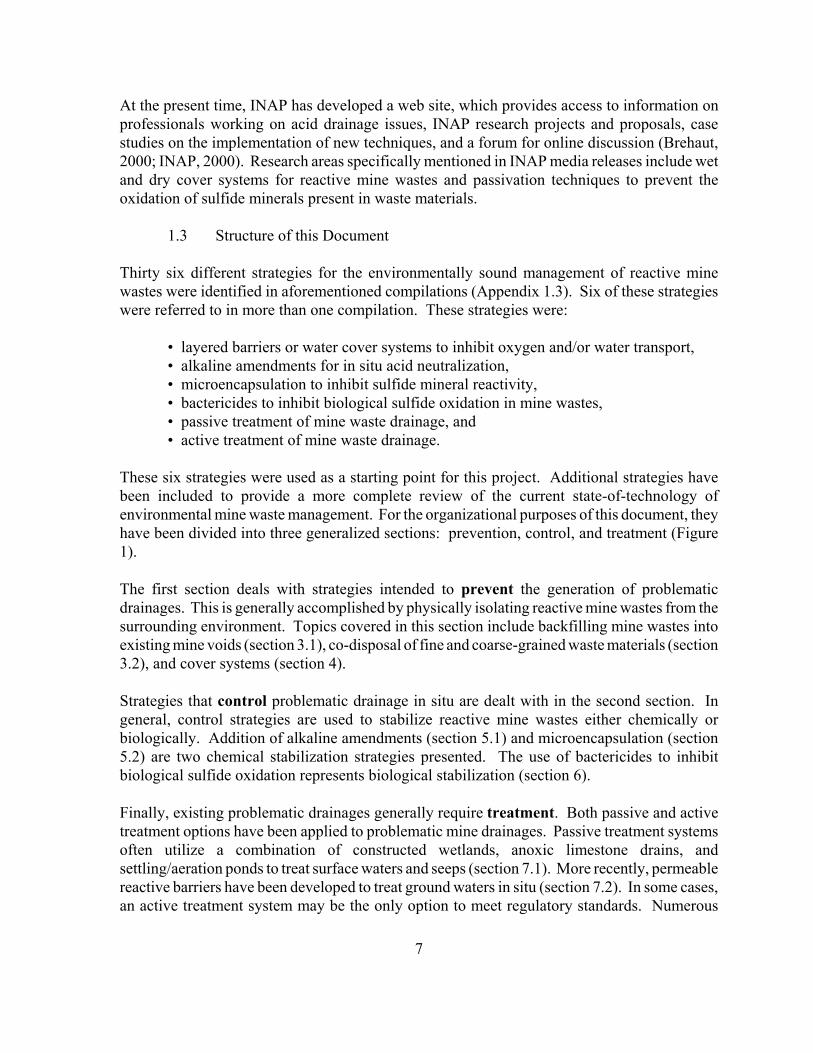
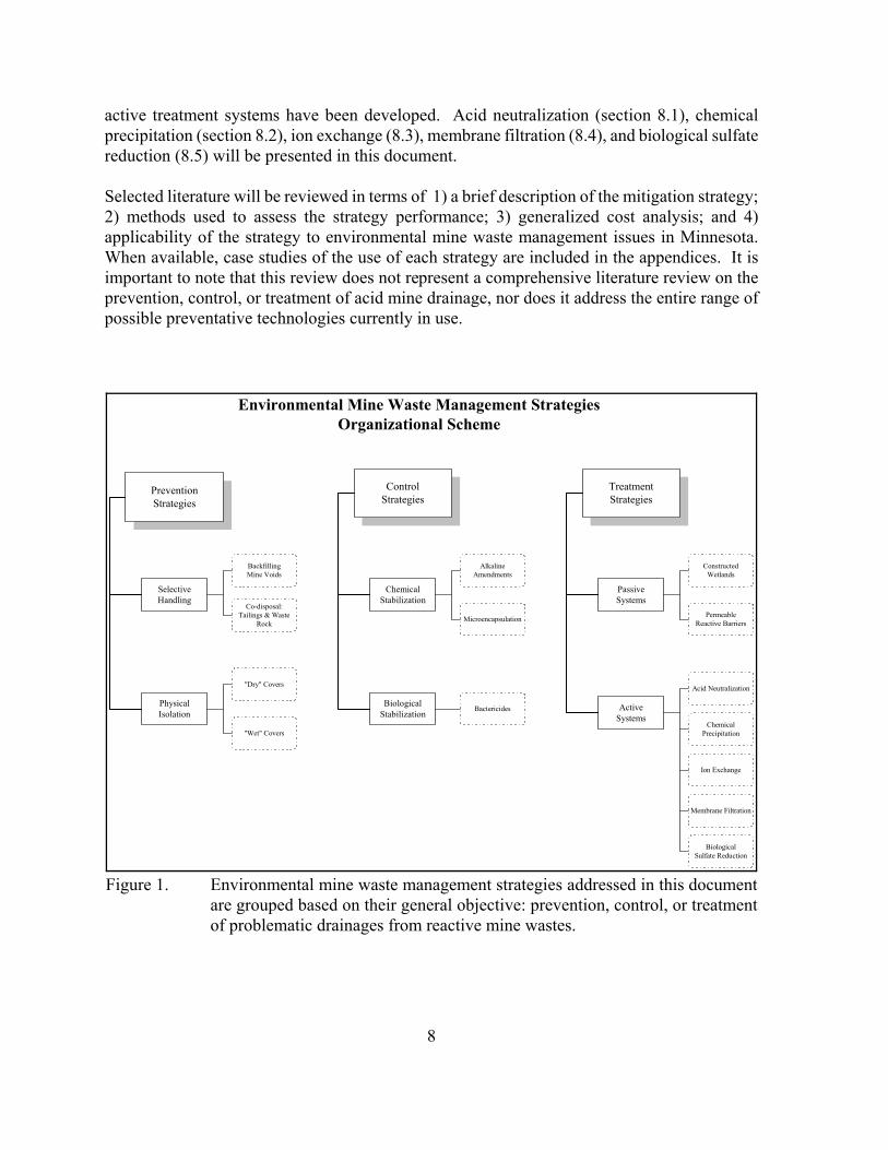
1.3 Structure of this Document
Thirty six different strategies for the environmentally sound management of reactive minewastes were identified in aforementioned compilations (Appendix 1.3). Six of these strategieswere referred to in more than one compilation. These strategies were:
• layered barriers or water cover systems to inhibit oxygen and/or water transport,• alkaline amendments for in situ acid neutralization, • microencapsulation to inhibit sulfide mineral reactivity,• bactericides to inhibit biological sulfide oxidation in mine wastes,• passive treatment of mine waste drainage, and• active treatment of mine waste drainage.
These six strategies were used as a starting point for this project. Additional strategies havebeen included to provide a more complete review of the current state-of-technology ofenvironmental mine waste management. For the organizational purposes of this document, theyhave been divided into three generalized sections: prevention, control, and treatment (Figure1).
The first section deals with strategies intended to prevent the generation of problematicdrainages. This is generally accomplished by physically isolating reactive mine wastes from thesurrounding environment. Topics covered in this section include backfilling mine wastes intoexisting mine voids (section 3.1), co-disposal of fine and coarse-grained waste materials (section3.2), and cover systems (section 4).
Strategies that control problematic drainage in situ are dealt with in the second section. Ingeneral, control strategies are used to stabilize reactive mine wastes either chemically orbiologically. Addition of alkaline amendments (section 5.1) and microencapsulation (section5.2) are two chemical stabilization strategies presented. The use of bactericides to inhibitbiological sulfide oxidation represents biological stabilization (section 6).
Finally, existing problematic drainages generally require treatment. Both passive and activetreatment options have been applied to problematic mine drainages. Passive treatment systemsoften utilize a combination of constructed wetlands, anoxic limestone drains, andsettling/aeration ponds to treat surface waters and seeps (section 7.1). More recently, permeablereactive barriers have been developed to treat ground waters in situ (section 7.2). In some cases,an active treatment system may be the only option to meet regulatory standards. Numerous
8
Environmental Mine Waste Management StrategiesOrganizational Scheme
PreventionStrategies
ControlStrategies
TreatmentStrategies
SelectiveHandling
BackfillingMine Voids
Co-disposal:Tailings & Waste
Rock
PhysicalIsolation
"Dry" Covers
"Wet" Covers
BiologicalStabilization
Bactericides
ChemicalStabilization
AlkalineAmendments
Microencapsulation
PassiveSystems
ConstructedWetlands
PermeableReactive Barriers
ActiveSystems
Acid Neutralization
ChemicalPrecipitation
Ion Exchange
Membrane Filtration
BiologicalSulfate Reduction
Figure 1. Environmental mine waste management strategies addressed in this documentare grouped based on their general objective: prevention, control, or treatmentof problematic drainages from reactive mine wastes.
active treatment systems have been developed. Acid neutralization (section 8.1), chemicalprecipitation (section 8.2), ion exchange (8.3), membrane filtration (8.4), and biological sulfatereduction (8.5) will be presented in this document.
Selected literature will be reviewed in terms of 1) a brief description of the mitigation strategy;2) methods used to assess the strategy performance; 3) generalized cost analysis; and 4)applicability of the strategy to environmental mine waste management issues in Minnesota.When available, case studies of the use of each strategy are included in the appendices. It isimportant to note that this review does not represent a comprehensive literature review on theprevention, control, or treatment of acid mine drainage, nor does it address the entire range ofpossible preventative technologies currently in use.
9
1.4. References
ACMER, 1998. Australian Centre for Mining Environmental Research. URL:http://acmer.com.au.
AMIRA, 2000. Australian Mineral Industries Research Association LTD. URL:http://www.amira.com.au.
ANSTO, 1999. Australian Nuclear Science and Technology Organisation.URL:http://www.ansto.gov.au/ansto/environment1/abt.html.
Bennett, J.W. 2000. Principal Research Scientist. ANSTO, Environmental Division, ManagingMine Wastes Project. personal communication.
Berndt, M.E.; Lapakko, K.A.; Jakel, M.E. 1999. In-pit disposal of taconite tailings:geochemistry. Final report. MN Dept. Nat. Resour., Division of Lands and Minerals, Saint Paul,MN. 77 p. plus appendices.
Brehaut, H. 2000. The International Network for Acid Prevention - a progress report. In: Proc.of the 5th Internat. Conf. on Acid Rock Drainage (ICARD), Denver, CO, May 21-24, pg 29-32.
CSIRO, 2000. Commonwealth Scientific and Industrial Research Organisation. URL:http://www.csiro.au
Eger, P. 1992. The use of sulfate reduction to remove metals from AMD. In: Proc. Am. Soc.for Surface Mining and Reclamation Meeting. ASSMR, pg 563-575.
Eger, P. 1994a. The use of sulfate reduction to remove metals from acid mine drainage. In:Internat. Land Reclamation and Mine Drainage Conf. and 3rd Internat. Conf. on the Abatementof Acidic Drainage, Pittsburgh, PA, April 24-29, 2, pg 412.
Eger, P.; Lapakko, K. 1988. Nickel and copper removal from mine drainage by a naturalwetland. In: Proc. 1988 Mine Drainage and Surface Mine Reclamation Conf., Pittsburgh, PA,April 19-21, 1, pg 301-309.
Eger, P.; Lapakko, K. 1989. The use of wetlands to remove nickel and copper from minedrainage. In: Constructed Wetlands for Wastewater Treatment. June 12-17, Chattanooga, TN,pg 780-787.
Eger, P.; Lapakko, K.; Chamberlain, P.G. 1984. Mixed disposal of waste rock and tailings toreduce trace metal release from waste rock. Symp. on Surface Mining, Hydrology,Sedimentology, and Reclamation, University of Kentucky, Lexington, KY, Dec. 2-7, pg 49-56.
10
Eger, P.; Lapakko, K.; Otterson, P. 1980. Trace metal uptake by peat: Interaction of a whitecedar bog and mining stockpile leachate. In: Proc. of the 6th Internat. Peat Congress, Duluth,MN, Aug. 17-23, pg 542-547.
Eger, P.; Wagner, J. 1995. Sulfate reduction for the treatment of acid mine drainage: long termsolution or short term fix? In: Mining and the Environment Conf. Proc., Sudbury, ON, May 28-June 1, 2, pg 515-524.
Eger, P., Wagner, J. 2001. Sulfate reduction - Designing systems for long term treatment. SME Annual Meeting, Denver, CO, Feb 26-28, Preprint 01-115.
Eger, P.; Wagner, J.; Kassa, Z.; Melchert, G. 1994. Metal removal in wetland treatment systems.In: Internat. Land Reclamation and Mine Drainage Conf. and 3rd Internat. Conf. on theAbatement of Acidic Drainage, Pittsburgh, PA, April 24-29, 1, pg 80-88.
Eger, P.; Wagner, J.; Melchert, G. 1996. The use of overland flow wetland treatment systemsto remove nickel from neutral mine drainage. In: Successes and Failures: Applying ResearchResults to Insure Reclamation Success. Proc. 13th Nat. Meeting, Knoxville, TN, May 18-23, pg580-589.
Eger, P.; Wagner, J.R.; Melchert, G. 1997. The use of a peat/limestone system to treat acid rockdrainage. In: Proc. 4th Internat. Conf. on Acid Rock Drainage (ICARD), Vancouver, BritishColumbia, May 31-June 6, 3, pg 1195-1209.
Eger, P.; Wagner, J.; Melchert, G.; Antonson, D.; Johnson, A. 2000. Long term wetlandtreatment of mine drainage at LTV Steel Mining Company’s Dunka Mine. MN Dept. Nat.Resour., Division of Lands and Minerals, 54 p. plus appendices.
Feasby, D.G.; Tremblay, G.A.; Weatherell, C.J. 1997. A decade of technology improvement tothe challenge of acid drainage- A Canadian perspective. In: Proc. 4th Internat. Conf. on AcidRock Drainage (ICARD), Vancouver, British Columbia, May 31-June 6, 1, pg i.
Greenhill, P.G. 2000. AMIRA international: AMD research through industry collaboration.In: Proc. of the 5th Internat. Conf. on Acid Rock Drainage (ICARD), Denver, CO, May 21-24,pg 13-19.
Gusek, J.J. et al. 2001. Draft: Handbook of Technologies for Avoidance and Mitigationof Metal Mine Drainage, Acid Drainage Technology Initiative (ADTI), Publ. byUniversity of Reno, NV, in progress.
Hoglund, L.O. 2000. Mitigation of the environmental impact from mining waste (MiMi)- a Swedish multidisciplinary research programme. In: Proc. of the 5th Internat. Conf. onAcid Rock Drainage (ICARD), Denver, CO, May 21-24, pg 3-12.
11
Hornberger, R.J.; Lapakko, K.A.; Krueger, G.E.; Bucknam, C.H.; Ziemkiewicz, P.F.; vanZyl,D.J.A.; Posey, H.H. 2000. The Acid Drainage Technology Initiative (ADTI). In: Proc. of the5th Internat. Conf. on Acid Rock Drainage (ICARD), Denver, CO, May 21-24, pg 41-50.
INAP. 2000. International Network for Acid Prevention. URL: http://www.inap.com.au.
Lapakko, K.A.; Antonson, D.A. 1989a. Alkaline addition reactor experiments: April 1989 statusreport. MN Dept. Nat. Resour., Division of Minerals, Saint Paul, MN, 28 p.
Lapakko, K.A.; Antonson, D.A. 1989b. Limestone column treatment of stockpile drainage: April1989 status report. MN Dept. Nat. Resour., Division of Minerals, Saint Paul, MN, 16 p.
Lapakko, K.A.; Antonson, D.A. 1989c. Seep 1 limestone bed: 1988 Progress report. MN Dept.Nat. Resour., Division of Minerals, Saint Paul, MN, 17 p.
Lapakko, K.A.; Antonson, D.A. 1990a. Laboratory experiments on the mixture of alkaline solidswith sulfide bearing rock. MN Dept. Nat. Resour., Division of Minerals, Saint Paul, MN, 37 p.plus appendices.
Lapakko, K.A.; Antonson, D.A. 1990b. Laboratory treatment of three acidic stockpile drainagesby limestone columns. MN Dept. Nat. Resour., Division of Minerals, Saint Paul, MN, 22 p. plusappendices.
Lapakko, K.A.; Antonson, D.A. 1990c. Pilot scale limestone bed treatment of the Seep 1 wasterock drainage. MN Dept. Nat. Resour., Division of Minerals, Saint Paul, MN, 24 p. plusappendices.
Lapakko, K.A.; Antonson, D.A. 1991. Mixing of limestone with acid producing rock. In: Proc.of the 2nd Internat. Conf. on the Abatement of Acidic Drainage, Montreal, Quebec, Sept. 16-18,pg 343-358.
Lapakko, K.; Antonson, D.; Jakel, E. 1998a. Mine waste characterization and drainagemitigation: Research summary 1998. MN Dept. Nat. Resour., Division of Minerals, Saint Paul,MN, 50 p.
Lapakko, K.A.; Antonson, D.A.; Wagner, J.R. 1997. Mixing of alkaline solids with finely-crushed acid-producing rock. In: Proc. 4th Internat. Conf. on Acid Rock Drainage (ICARD),Vancouver, British Columbia, May 31-June 6, pg 1345-1360.
Lapakko, K.A.; Antonson, D.A.; Wagner, J.R. 2000. Mixing of rotary kiln fines with fine-grained acid-producing rock. In: Proc. of the 5th Internat. Conf. on Acid Rock Drainage(ICARD), Denver, CO, May 21-24, pg 901-910.
12
Lapakko, K.; Eger, P. 1981. Trace metal removal from mining stockpile runoff using peat,wood chips, tailings, till, and zeolite. Symp. on Surface Mining, Hydrology, Sedimentology, andReclamation, University of Kentucky, Lexington, KY, Dec. 7-11, pg 105-116.
Lapakko, K.; Eger, P. 1983. Passive treatment of sulfide stockpile runoff. In: Proc. 1983 Nat.Conf. on Environmental Engineering, A. Medine and M. Anderson eds. ASCE, New York, pg643-651.
Lapakko, K.; Eger, P. 1988. Trace metal removal from stockpile drainage by peat. In: Proc.1988 Mine Drainage and Surface Mine Reclamation Conf., Pittsburgh, PA, April 19-21, 1, pg291-300.
Lapakko, K.A.; Eger, A.P.; Strudell, J.D. 1986a. Low-cost removal of trace metals fromcopper-nickel mine stockpile drainage. Vol 1, Laboratory and field investigations. Report to theUS Bureau of Mines, Contract J0205047, 103p.
Lapakko, K.A.; Eger, A.P.; Strudell, J.D. 1986b. Low-cost removal of trace metals fromcopper-nickel mine stockpile drainage. Vol 2, Trace metal sequestration by peat, other organics,tailings, and soils: a literature review. Report to the US Bureau of Mines, Contract J0205047,45p.
Lapakko, K.; Jakel, M.E. 1999. Summary of potential impacts of taconite tailings disposal in theMinorca Pit on water quality in the Missabe Mountain Pit. MN Dept. Nat. Resour., Division ofLands and Minerals, Saint Paul, MN, 29 p. plus appendices.
Lapakko, K.; Strudell, J.; Eger, P. 1983. Sulfide stockpile leachate flow through a tailing bed:trace metal removal and flow modeling for a low maintenance treatment system. Symp. onSurface Mining, Hydrology, Sedimentology, and Reclamation, University of Kentucky,Lexington, KY, Nov. 27-Dec. 2, pg 321-327.
MEND. 2001. Mine Environment Neutral Drainage Program Manual, Report 5.4.2, Volumes1-6. (eds: G.A. Tremblay and C.M. Hogan) Energy, Mines and Resources Canada, CandianCentre for Mineral and Energy Tecnology (CANMET).
MN DNR. 1998. October 1997 (Q2 F1998) Report on state mineral leasing activities. MNDept. Nat. Resour., Division of Minerals, Minerals Leasing and Mineral Rights ManagementSection, St. Paul, MN.
Minnesota Department of Revenue, 1997. Personal communication with Tom Schmucker,Administrative engineer, Eveleth, MN.
Minnesota Environmental Quality Board. 1979. Regional copper-nickel study, Executivesummary, volume 1. MN State Planning Agency, St. Paul, MN, 118 p.
13
MISTRA, 1998. Programme plan for the period 1999-2000. Mitigation of the environmentalimpact from mining waste. A MISTRA research programme, 50 p.
PA DEP, 1998. Coal mine drainage prediction and pollution prevention in Pennsylvania. ThePennsylvania Dept. of Environmental Protection. Harrisburg, PA, 375p.
Parker, G.; Robertson, A. 1999. Acid drainage. Occasional Paper No. 11. Australian Mineralsand Energy Environment Foundation, Melbourne, Victoria, 227 p.
Skousen, J.G.; Ziemkiewicz, P.F. 1995. Acid mine drainage: Control & treatment. WestVirginia University and the National Mine land Reclamation Center, Morgantown, WV, 255p.
Skousen, J.; Rose, A.; Geidel, G.; Forman, F.; Evans, R.; Hellier, W. 1998. A Handbook ofTechnologies for Avoidance and Remediation of Acid Mine Drainage. Acid DrainageTechnology Initiative (ADTI), Morgantown: National Mine Land Reclamation Center at WestVirginia University.
STS Consultants Ltd. 1993. Final closure plan for Dunka Mine. Report to LTV Steel MiningCompany, Hoyt Lakes, MN, 218 p. plus appendices.
STS Consultants Ltd. 1994a. Stockpile 8018 capping, Dunka Mine NPDES Permit No.MN0042579. Report to LTV Steel Mining Company, Hoyt Lakes, MN, 6 p. plus appendices.
STS Consultants Ltd. 1994b. 051 treatment system, Dunka Mine NPDES Permit No.MN0042579. Report to LTV Steel Mining Company, Hoyt Lakes, MN, 14 p. plus appendices.
Tremblay, G. 2000. The Canadian Mine Environmental Neutral Drainage 2000 (MEND 2000)Program. In: Proc. of the 5th Internat. Conf. on Acid Rock Drainage (ICARD), Denver, CO,May 21-24, pg 33-40.
Tremblay, G., Weatherell, C. 2000. MEND 2000: Progress through partnerships.http://mend2000.nrcan.gc.ca/mend2000/cim.html.
US EPA. 1983. Design manual: Neutralization of acid mine drainage. U.S. EnvironmentalProtection Agency, Industrial Environmental Research Laboratory. EPA-600/2-83-001, 231p.
US EPA. 1999. United States Environmental Protection Agency, Mine Waste TechnologyProgram. URL: http://www.epa.gov/ ORD/NRMRL/std/mtb/activities.htm.
14
2. Geochemical Background
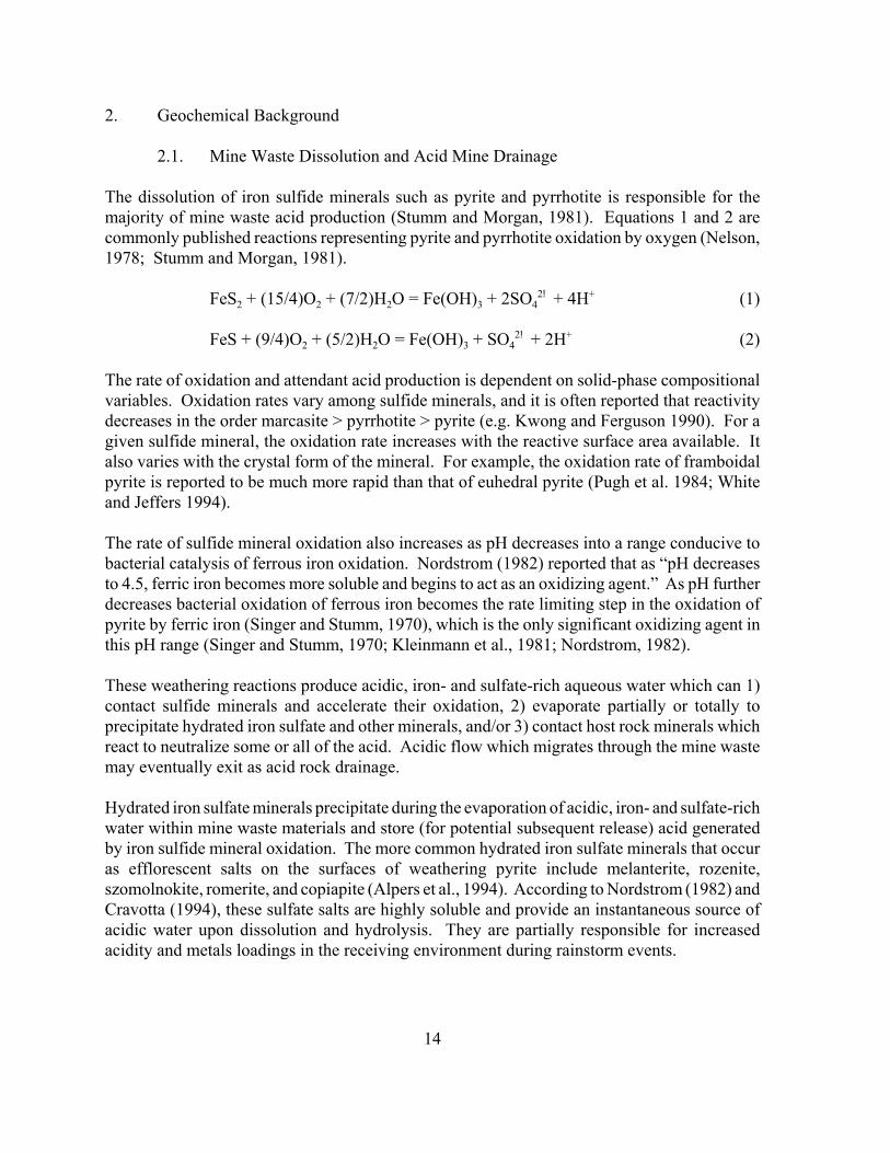
2.1. Mine Waste Dissolution and Acid Mine Drainage
The dissolution of iron sulfide minerals such as pyrite and pyrrhotite is responsible for themajority of mine waste acid production (Stumm and Morgan, 1981). Equations 1 and 2 arecommonly published reactions representing pyrite and pyrrhotite oxidation by oxygen (Nelson,1978; Stumm and Morgan, 1981).
FeS2 + (15/4)O2 + (7/2)H2O = Fe(OH)3 + 2SO42! + 4H+ (1)
FeS + (9/4)O2 + (5/2)H2O = Fe(OH)3 + SO42! + 2H+ (2)
The rate of oxidation and attendant acid production is dependent on solid-phase compositionalvariables. Oxidation rates vary among sulfide minerals, and it is often reported that reactivitydecreases in the order marcasite > pyrrhotite > pyrite (e.g. Kwong and Ferguson 1990). For agiven sulfide mineral, the oxidation rate increases with the reactive surface area available. Italso varies with the crystal form of the mineral. For example, the oxidation rate of framboidalpyrite is reported to be much more rapid than that of euhedral pyrite (Pugh et al. 1984; Whiteand Jeffers 1994).
The rate of sulfide mineral oxidation also increases as pH decreases into a range conducive tobacterial catalysis of ferrous iron oxidation. Nordstrom (1982) reported that as “pH decreasesto 4.5, ferric iron becomes more soluble and begins to act as an oxidizing agent.” As pH furtherdecreases bacterial oxidation of ferrous iron becomes the rate limiting step in the oxidation ofpyrite by ferric iron (Singer and Stumm, 1970), which is the only significant oxidizing agent inthis pH range (Singer and Stumm, 1970; Kleinmann et al., 1981; Nordstrom, 1982).
These weathering reactions produce acidic, iron- and sulfate-rich aqueous water which can 1)contact sulfide minerals and accelerate their oxidation, 2) evaporate partially or totally toprecipitate hydrated iron sulfate and other minerals, and/or 3) contact host rock minerals whichreact to neutralize some or all of the acid. Acidic flow which migrates through the mine wastemay eventually exit as acid rock drainage.
Hydrated iron sulfate minerals precipitate during the evaporation of acidic, iron- and sulfate-richwater within mine waste materials and store (for potential subsequent release) acid generatedby iron sulfide mineral oxidation. The more common hydrated iron sulfate minerals that occuras efflorescent salts on the surfaces of weathering pyrite include melanterite, rozenite,szomolnokite, romerite, and copiapite (Alpers et al., 1994). According to Nordstrom (1982) andCravotta (1994), these sulfate salts are highly soluble and provide an instantaneous source ofacidic water upon dissolution and hydrolysis. They are partially responsible for increasedacidity and metals loadings in the receiving environment during rainstorm events.
15
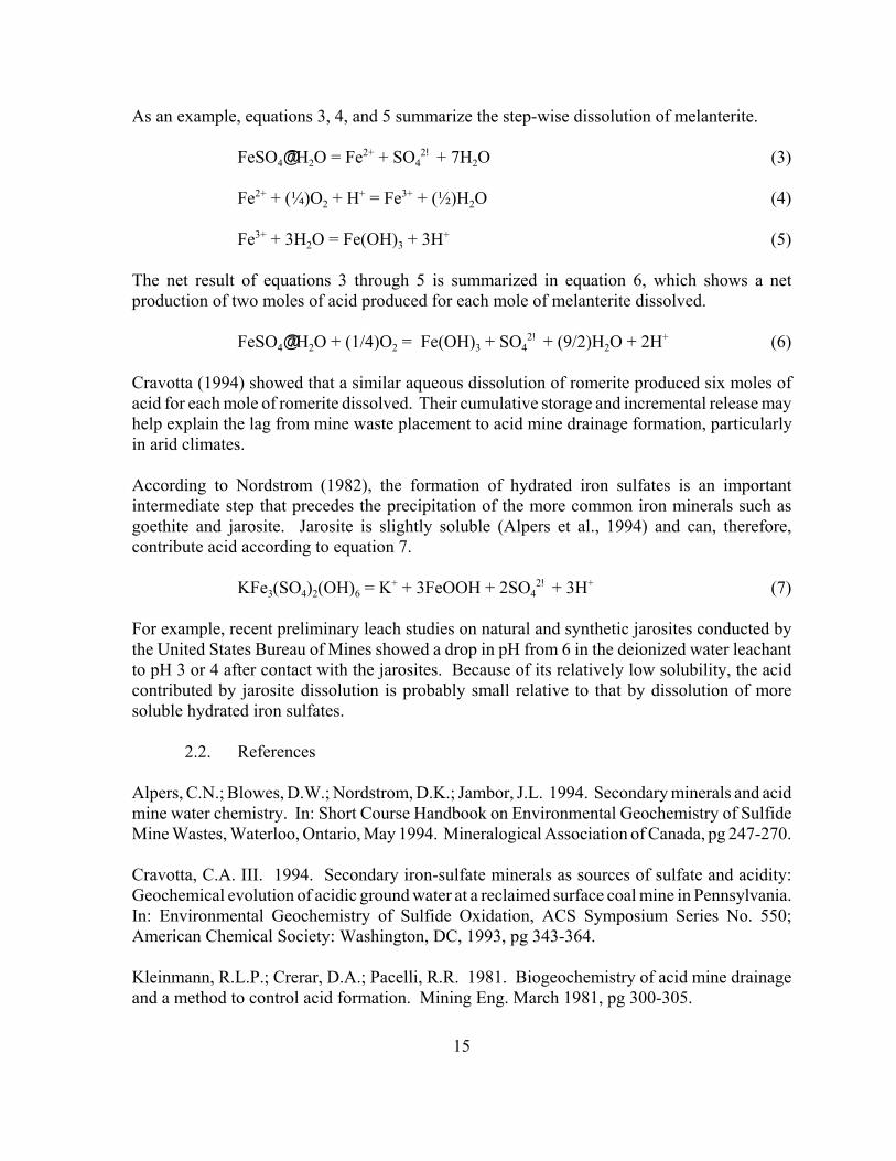
As an example, equations 3, 4, and 5 summarize the step-wise dissolution of melanterite.
FeSO4@7H2O = Fe2+ + SO42! + 7H2O (3)
Fe2+ + (¼)O2 + H+ = Fe3+ + (½)H2O (4)
Fe3+ + 3H2O = Fe(OH)3 + 3H+ (5)
The net result of equations 3 through 5 is summarized in equation 6, which shows a netproduction of two moles of acid produced for each mole of melanterite dissolved.
FeSO4@7H2O + (1/4)O2 = Fe(OH)3 + SO42! + (9/2)H2O + 2H+ (6)
Cravotta (1994) showed that a similar aqueous dissolution of romerite produced six moles ofacid for each mole of romerite dissolved. Their cumulative storage and incremental release mayhelp explain the lag from mine waste placement to acid mine drainage formation, particularlyin arid climates.
According to Nordstrom (1982), the formation of hydrated iron sulfates is an importantintermediate step that precedes the precipitation of the more common iron minerals such asgoethite and jarosite. Jarosite is slightly soluble (Alpers et al., 1994) and can, therefore,contribute acid according to equation 7.
KFe3(SO4)2(OH)6 = K+ + 3FeOOH + 2SO42! + 3H+ (7)
For example, recent preliminary leach studies on natural and synthetic jarosites conducted bythe United States Bureau of Mines showed a drop in pH from 6 in the deionized water leachantto pH 3 or 4 after contact with the jarosites. Because of its relatively low solubility, the acidcontributed by jarosite dissolution is probably small relative to that by dissolution of moresoluble hydrated iron sulfates.
2.2. References
Alpers, C.N.; Blowes, D.W.; Nordstrom, D.K.; Jambor, J.L. 1994. Secondary minerals and acidmine water chemistry. In: Short Course Handbook on Environmental Geochemistry of SulfideMine Wastes, Waterloo, Ontario, May 1994. Mineralogical Association of Canada, pg 247-270.
Cravotta, C.A. III. 1994. Secondary iron-sulfate minerals as sources of sulfate and acidity:Geochemical evolution of acidic ground water at a reclaimed surface coal mine in Pennsylvania.In: Environmental Geochemistry of Sulfide Oxidation, ACS Symposium Series No. 550;American Chemical Society: Washington, DC, 1993, pg 343-364.
Kleinmann, R.L.P.; Crerar, D.A.; Pacelli, R.R. 1981. Biogeochemistry of acid mine drainageand a method to control acid formation. Mining Eng. March 1981, pg 300-305.
16
Nelson, M. 1978. Kinetics and mechanisms of the oxidation of ferrous sulfide. Ph. D. Thesis,Stanford University, Palo Alto, CA.
Nordstrom, D.K. 1982. Aqueous pyrite oxidation and the consequent formation of secondaryiron minerals. In: Acid Sulfate Weathering. J.A. Kittrick, D.S. Fanning, and L.R. Hossner(eds.), Soil Sci. Soc. America Spec. Pub. 10, Madison, WI, pg 37-56.
Singer, P.C.; Stumm, W. 1970. Acid mine drainage: The rate determining step. Science, 167,pg 1121-1123.
Stumm, W., Morgan, J. J. 1981. Aquatic Chemistry-An introduction emphasizing chemicalequilibria in natural waters. John Wiley and Sons, Inc. New York. 780p.
17
PREVENTION STRATEGIES
Whether or not a mine waste produces problematic drainage depends on a wide array ofvariables that describe the physical, chemical, and mineralogical characteristics of the waste,pre-existing site conditions, climate, and government regulations. Consequently, there is nosingle, correct approach to environmental mine waste management. One approach is to usestrategies that prevent the generation of problematic drainages in the first place. Typicalprevention strategies involve constructing a barrier between reactive mine wastes and air (i.e.oxygen) and/or water. This section will review the use of backfill options and cover systemscommonly used to physically isolate reactive mine waste materials from the surroundingenvironment.
3. Selective Handling of Reactive Mine Wastes
3.1. Backfilling Reactive Mine Wastes
3.1.1. Objectives of Backfilling Reactive Mine Wastes
Backfilling existing mine voids with reactive mine waste materials is a prevention strategycurrently practiced at both surface and underground mines. In terms of environmental minewaste management, the goal of backfilling is to isolate reactive mine wastes from the atmosphereand/or water. Additional benefits to the mining operation include increased stability ofunderground mine workings and reduced land development, disposal, and reclamation costs.
Numerous techniques for backfilling mine voids have evolved over the years. In a situationwhere an open pit is to be backfilled, transporting mine wastes from a temporary storage areamay simply involve truck hauling or pumping a tailings slurry. Typically, reactive materials areplaced near the center of the pit. The surrounding material usually consists of less reactive minewaste that limit exposure to water and oxygen. Highly reactive mine wastes often requireadditional mitigative measures. Ideally, the reactive mine waste can be encapsulated with netneutralizing mine wastes. However, if these materials are not available locally, alkalinematerials such as limestone or fly ash can be intermixed with the reactive mine waste toneutralize any acid generated.
Prior to mine closure, backfilled pits must be reclaimed. Reclamation can vary from a simplereplacement of topsoil and vegetation to complex multi-layer cover schemes (see section 4.2).Alternatively, if the pit intersects the ground water table, it may be preferable to inundate thewaste materials. A major benefit of establishing a water cover is that oxygen diffusion will belimited, reducing the potential for acid generation (see section 4.3).
Occasionally, underground mines can be backfilled using ordinary haul trucks and bulldozers.However, more complicated methods, such as hydraulic flushing or pneumatic stowing arefrequently required. Hydraulic flushing involves pumping fill material as a slurry into the void.This method has several drawbacks. Operators have very little control over the direction and
18
compaction of the backfill that results. Furthermore, the particle size distribution of the fillmaterial varies with respect to slurry velocity during deposition. Finally, this method requirestransport of relatively large volumes of water into the mine, which may or may not be beneficial(Walker, 1993).
Pneumatic stowing is a second method for backfilling mine voids, which eliminates the volumeof water introduced into the mine. While a greater degree of compaction can be achieved usingpneumatic stowing, abrasion of the injection nozzle and elbows leads to rapid equipment failure(Walker, 1993). This problem has been addressed, in part, by the development of a highefficiency ejector that uses a supersonic airstream to project fill material horizontally into thevoid (Burnett et al., 1995).
Handling of mine wastes, particularly tailings, can often present problems. A common goal isto create a high density fill material using paste technology. Pastes are mixtures of tailings andwater, similar to a slurry. However, pastes are differentiated from slurries by the fact that theydo not segregate with respect to particle size when at rest. In order for this to occur, a paste mustcontain approximately 15% fines (< 20 um) by weight. The fines retain moisture due to theirhigh surface tension, preventing segregation (Cincilla et al., 1997). Portland cement can beadded to the paste to increase strength and durability (Cincilla et al., 1997).
Similar to the open pit situation, alkaline materials (e.g. limestone, fly ash etc.) are often usedto increase backfill strength and neutralize acidic drainage. However, laboratory studies havedemonstrated the preferential dissolution of alkaline binders in cemented paste backfills(Bertrand et al., 2000). These results also indicated that the backfill material became passivated,although the exact mechanism of passivation was unclear. Consequently, cemented pastebackfills may not provide long-term buffering against acidic drainage generated withinbackfilled mine works.
3.1.2. Monitoring Water Quality Associated with Backfilled Mine Works
Post-closure monitoring must be included in the disposal design in order to determine the overalleffectiveness of a backfill program. Objectives are likely to include monitoring the movementof water into and out of the backfill as well as water quality. If poor water quality is anticipated,a liner and underdrain system should be installed prior to construction. These are necessary tocollect drainage for additional treatment if needed.
Monitoring instrumentation may include a series probes and piezometers to measure gasconcentrations (e.g. oxygen), moisture content, and water levels within the backfill. Theseinstruments can easily be connected to an automated datalogger system to streamline datacollection. Both ground and surface water quality should be monitored. Lysimeters and wellscan be installed in strategic locations to obtain ground water quality samples. Seeps and pondedwater, in the case of flooded wastes, also give an indication of the extent to which backfillmaterials may have reacted with ground and surface waters.
19
3.1.3. Economic Benefits of Backfilling Mine Voids
Backfilling mine voids with reactive mine waste materials can be a cost effective approach toenvironmental mine waste management. This is particularly true if abandoned pits or mineworkings are available on-site. If mine wastes are to be redeposited in an operational mine, atemporary disposal plan will be required. In this situation, mine wastes are effectively disposedof twice (once as they are removed from the mine and again to their final disposal location),which increases design, transportation, handling, and management costs. However, these costscan be offset by the savings due to reductions in storage volume required. As with any disposalsituation, the economic impacts of each variable must be evaluated on a site-specific basis.
3.1.4. Potential Application of Backfill Technology in Minnesota
Numerous mined out natural iron ore pits exist along the Cuyuna and Mesabi Iron Ranges innorthern Minnesota. If mineral development were to occur in these areas, backfilling these pitswith reactive mine wastes may appear to be a feasible option. However, potential impacts toaquifers (i.e. local drinking water supplies) must be considered. According to the Laws ofMinnesota, 1996, Chapter 407, Section 56, the Minnesota Pollution Control Agency may issuea permit to dispose of fine taconite tailings into taconite mine pits provided, “the proposerdemonstrates through an environmental impact statement and risk assessment that the depositionwill not pose an unreasonable risk of pollution or degradation of groundwater.” It should benoted that this law refers specifically to taconite mine wastes, which generally do not produceproblematic drainage. Sulfide-bearing mine wastes may have a higher probability of impactinglocal ground waters due to their reactivity and the likelihood that mine workings will intersectlocal aquifers. Whether or not backfilling open pits with reactive materials is a practicable minewaste management option in Minnesota will largely depend on the solid-phase characteristicsof the mine waste material and the hydrogeology of the open pit and surrounding area.Consequently, practicability of this strategy is likely to be determined by site-specificevaluations.
3.2. Co-disposal of Tailings and Waste Rock as a Preventative Strategy
3.2.1. Objectives of Co-disposal
Traditional handling of mining wastes calls for separate disposal of coarse waste rock and fine-grained tailings. However, recent investigations into the co-disposal of tailings and waste rocksuggest that this strategy has both environmental and economic benefits. Co-disposal simplyrefers to the combining of tailings and waste rock prior to disposal. Layered co-disposalinvolves placing layers of tailings at predefined intervals within a waste rock deposit duringconstruction. In both cases, the resulting deposit has improved physical and chemicalcharacteristics that decrease the potential for acid generation and trace metal release.
Generation of problematic drainages is the result of sulfide mineral oxidation, which is, in turn,a function of the amount of water and oxygen present in reactive mine wastes (equations 1 and
20
2). The primary goal of co-disposal is to exploit the hydraulic properties of fine-grainedmaterials (i.e. tailings) to limit exposure of mine waste materials to oxygen. This isaccomplished by mixing tailings and waste rock prior to disposal. The high moisture-retentioncapacity of the tailings creates saturated conditions throughout the deposit. Since oxygendiffuses more slowly through water than air (Table 8), the rate of sulfide oxidation is minimized.Additional benefits of co-disposal include:
• short-term control as reactive wastes are disposed,• increased physical stability of the deposit due to waste rock sheer strength,• increased density within the deposit,• increased water recovery from tailings,• relatively high surface area associated with fine-grained material increases potentialfor adsorptive trace metal removal,• certain fine-grained waste materials (e.g. taconite tailings) may contain acidneutralizing minerals, and• reduced land development, disposal, and reclamation costs.
Despite these advantages, co-disposal of tailings and waste rock may involve considerableplanning and design. Both pumped and layered co-disposal strategies involve departures fromconventional waste handling and transportation techniques (Table 1). If the objective is anintermixed deposit of tailings and coarse reject, the two waste streams can be combined andpumped to an impoundment or abandoned pit. However, specialized equipment is needed tohandle the additional strain on pumps and pipelines. Waste handling and transportation issuesalso arise for layered co-disposal situations. Compaction of the tailings layers maximizes thecapillary effect. However, compaction requires dewatered tailings. Consequently, practicalissues of how to transport dewatered tailings to the impoundment must be addressed. Thisusually involves truck hauling (Table 1). In general, co-disposal of tailings and waste rock willinvolve a greater effort in the areas of deposit design, disposal scheduling, and supervision.
3.2.2. Evaluation of Co-disposal Performance
Generation of problematic drainages in waste rock piles is directly related physical as well aschemical processes. Without a good conceptual model of the disposal system, performance isdifficult to evaluate. Numerous efforts have been made to characterize the physical processes(i.e. water and oxygen flow) operating within waste rock piles and fine-grained materials(Nicholson et al. 1989; Lefebvre and Gelinas 1995; Nichol et al. 2000; Wilson et al. 2000b).Quantification of these processes is essential in determining mechanisms that control drainagechemistry. By understanding these mechanisms, they can be exploited to optimize waste rockdeposit design and develop monitoring programs to evaluate overall performance.
21
Table 1. Several practical waste handling design and transportation issues must beaddressed when considering a co-disposal strategy for mine waste management.
Co-disposal Description Issue Consider...
Pumped
pump & pipeline wear
1. high-pressure, large borepumps
2. ceramic- or polyurethane-linedpipes
3. particle shape4. decrease solids concentration
pipeline blockages 1. increase flow velocity2. increase pressure
fines wash out of porespaces among coarseparticles
1. high coarse to fine mass ratio2. small size gap between coarse
and fine materials3. decrease flow velocity
hydraulic sorting upondischarge 1. direct discharge up slope
Layered transportation of dewateredtailings 1. truck hauling
22
3.2.3. Economic Benefits of Co-disposal of Mine Wastes
Pumping, specialized heavy duty equipment, and/or transportation of dewatered tailings willincrease the expense incurred by co-disposal of fine and coarse waste materials. However, thesecosts may be offset by the savings due to reductions in storage volume required. For example,a coal operation in Australia pumped tailings and coarse reject to an abandoned pit, resulting ina reported savings of $0.52/ton of product (Williams, 1997). This estimate may be higher thancan be expected at other sites due to the availability of an abandoned pit and site-specificproblems associated with conventional waste disposal. An alternative estimate predicted a 20%reduction in operating costs (Sellgren and Addie, 1998). As with any disposal situation, theeconomic impacts of each variable must be evaluated on a site-specific basis (Table 2).
Table 2. Costs associated with co-disposal of tailings and waste rock may be reduced,depending on the relative savings compared to conventional disposal.
Conventional Disposal Cost Items Economic Benefit/Liability of Co-Disposal
tailings thickener(capital, operation, maintenance)
A portion of the tailings stream may be able tobypass the thickener.
tailings impoundment construction Increased density of the deposit reduces thesize requirements.
acquiring land Increased density of the deposit reduces theamount of land required.
pumps & pipeline(capital, operation, maintenance)
Considerably higher due to the need for heavyduty equipment.
water recovery site-specific
reclamation site-specific
coarse reject hopper A hopper to combine tailings and coarsestreams will still be necessary.
conveyor system(capital, operation, maintenance) None required
truck(capital, operation, maintenance, replacement)
No truck hauling for pumped co-disposal. May be a factor for layered co-disposal.
haul roads(construction, maintenance)
No truck hauling for pumped co-disposal. May be a factor for layered co-disposal.
drainage management(collection, treatment) site-specific
3.2.4. Co-disposal Studies and Applications in Minnesota
23
Several laboratory-scale investigations into the effectiveness of tailings and waste rock co-disposal have been conducted (Lapakko and Eger, 1981; Iwasaki et al., 1982; Eger et al., 1984;Lapakko et al., 1983, 1985, 1986a, b; Johnson et al., 1995; Fortin et al., 2000; Lamontagne etal., 2000). This discussion will focus on those using tailings and mine wastes from northernMinnesota.
3.2.4.1. MN DNR Joint Disposal Studies
Laboratory and field studies examining the ability of taconite tailings to passively treat stockpiledrainages were conducted by the MN DNR (Lapakko and Eger, 1981; Eger et al., 1984; Lapakkoet al., 1983, 1985, 1986a, b). The two-phase experimental program was conducted under USBureau of Mines funding to examine the feasibility of removing copper, nickel, cobalt, and zincfrom stockpile drainage using readily available materials in low cost, low maintenance systems(Lapakko et al., 1986a,b). The first phase was a laboratory program using: 1) batch experimentsas a screening program; and 2) column experiments to select the most promising materials forfield trials (Lapakko and Eger, 1981; Lapakko et al., 1985, 1986a).
Low sulfide tailings were chosen for the phase two field testing, utilizing both treatment bedsand joint disposal bins. Saturated and unsaturated flow tailings treatment beds demonstrated thegreatest removal efficiency for copper and lowest for nickel (Lapakko et al., 1983, 1985, 1986a).
In the joint disposal study, total effluent from waste rock was reduced 34% by the addition oftailings and 66% by the addition of tailings followed by an additional cover layer of tailings andvegetation (Eger et al., 1984; Lapakko et al., 1985, 1986a). During the 1983 field season, bothtreatments produced effluent that met the copper guideline; the nickel concentration was alsoreduced, but it nevertheless exceeded the guideline by more than a factor of two (Table 3).
Furthermore, these successes were short-lived. After three years, metal concentrations hadincreased three to five fold and effluent pH had begun to decrease (MN DNR, 1987). Amongthe conclusions from the MN DNR joint disposal field study were the following generalconsiderations for operational-scale co-disposal (Lapakko et al., 1985, 1986a):
• optimal tailings and waste rock incorporation methods to reduce the area required foroverall waste disposal,• correct positioning of the discharge pipe relative to the deposit to avoid hydraulicsorting,• quantification of the hydraulic and metal removal capacities of the system,• construction of toe ditch and berms, settling basins, or similar structures to minimizetotal suspended solids in the effluent,• deposit reclamation to reduce erosion, and• potential long-term trace metal release from the tailings.
24
Table 3. Flow-weighted concentrations from joint disposal bins compared to effluentguidelines (Lapakko et al., 1985).
ParameterGuidelineLimitation
(mg/L)
Average flow-weighted concentration (mg/L)
Controls UnvegetatedTailings
VegetatedTailings
Cu 0.15 0.31 0.11 0.06
Ni 0.75 3.2 1.58 1.78
Co 0.15 0.11 0.06 0.05
Zn 0.75 0.23 0.07 0.15
pH 6.0-9.0 6.0 6.2 6.2
TSS 20.0 1.4 3200 280
Table 4. Calcite-bearing taconite tailings reduced the amount of nickel and copper releasefrom Duluth Complex ore (Iwasaki et al., 1982).
Parameter Ore Ore +taconite tailings
pH1 6.3 6.6-6.7
Cu (mg/L)1 0.09 below detection
Ni1 3 0.95-1.8
SO42 1500 900-1300
1 120 day leach test2 after 8 months
25
3.2.4.2. Minnesota Mineral Research Center Studies InvolvingCo-disposal
The Minnesota Minerals Research Center also conducted laboratory studies in which thepotential use of carbonate-bearing taconite tailings as acid neutralizing additives wasinvestigated (Iwasaki, 1982). Shake flask leaching of Duluth Complex (copper-nickel) ore wasconducted using 0.5%, 1.0%, and 2.0% taconite tailings. The results indicated that taconitetailings did provide some neutralization and decreased heavy metal release from the ore (Table4).
3.2.4.3. Full-Scale Application of Co-disposal in a TaconiteTailings Basin
Finally, there is one known, operational-scale case of waste rock disposal within a tailings basinin Minnesota. Upon closure of the Dunka Mine near Babbitt, MN, LTV Steel Mining Companydisposed of approximately 262,000 long tons of high sulfur Virginia Formation hornfels wasterock (LTV, 1996). Hornfels and dolomitic limestone (ratio of 8.35:1) were encapsulated withina section of their taconite tailings basin. Monitoring wells were installed in 1995, however,subsequent mining activity damaged the two wells to the extent that they were no longer usable.Two additional wells were installed in the spring of 1998. Monitoring of water quality in thesewells and local seeps continues on a quarterly basis (Table 5).
Table 5. Water chemistry measured from monitoring wells and seeps in LTV SteelMining Company’s tailings basin between March 1995 and February 2000.Concentrations in µg/L unless noted otherwise. See Appendix 2 for a moredetailed summary (Clark, 2000).
ParameterWells (N=43) Seeps (N=112)
Range Average Range Average
pH 7.0 - 10.0 8.3 7.1 - 8.71 7.9
Cu <1 - 125 13 <1 - 80.8 1.4
Ni <1 - 243 19 <1 - 13.6 1.4
Co <1 - 20.6 4 <1 - 7.8 1.0
Zn <10 - 181 27 <10 - 20 6.4
SO4 (mg/L) 54.5 - 825 153 132 - 5311 2101 N = 84
26
Between 1996 and 1999, water samples were collected from a seep along the southwest side ofthe tailings basin as part of a MN DNR-University of Minnesota joint study (Berndt et al., 1999).High sulfate levels in these samples indicate transport of sulfate from the hornfels rock (Table6). However, it cannot be determined whether the sulfate was the result of rinsing of oxidationproducts produced prior to placement of the hornfels rock in the tailings basin, or subsequentcontinued sulfide oxidation within the tailings basn. Seepage pH and trace metal levels wereconsidered non-problematic. This suggested that the additional dolomite and taconite tailings(i.e. ankerite) contained adequate capacity for neutralization. Iron oxides present in the tailings(approximately 19 wt%) were believed to provide sites for trace metal adsorption (Berndt et al.,1999).
Table 6. Summary of water chemistry measured from a seep on the southwest side of LTVSteel Mining Company’s tailings basin between June 1996 and February 1999.Appendix 2 for a more detailed summary. Concentrations in µg/L unless notedotherwise.
Parameter Range Average N
pH 7.1-7.7 7.3 11
Cu 0.0-1.5 0.7 11
Ni 0.9-3.3 1.8 11
Co 1.6-5.1 2.6 11
Zn 5.0-30.2 17.3 11
SO4 (mg/L) 169-284 230 11
In summary, results from laboratory studies suggest that co-disposal of tailings and waste rockcan be used to mitigate problematic drainages (Lapakko and Eger, 1981; Iwasaki et al., 1982;Eger et al., 1984; Lapakko et al., 1983, 1985, 1986a, b; Johnson et al., 1995; Fortin et al., 2000;Lamontagne et al., 2000). However, these studies indicate that practical issues of waste depositdesign, use of alkaline additives, transportation and discharge of wastes, reclamation, and long-term contaminant release present potential technical, economic, and environmental problems.Individual operations must resolve these issues (i.e. large-scale field tests) before co-disposalstrategies can be considered a viable waste disposal strategy.
27
3.3. References for Selective Handling of Reactive Mine Wastes
Aiken, S.R.; Pettit, C.M.; Halbert, B.E.; Knapp, R.A. 1999. Whistle mine closure modellingstudies and water treatment considerations. In: Mining and the Environment Conf. Proc.,Sudbury, Ontario, Sept. 13-17, 2, pg 771-780.
Amaratunga, L.M. 2000. Designing a strong total tailings pastefill using cold-bonded tailingsagglomerates. CIM Bulletin, 93, 1043, pg 119-122.
Berndt, M.E.; Lapakko, K; Jakel, E. 1999. In-pit disposal of taconite tailings: geochemistry.Final Report. MN DNR, Division of Lands and Minerals, Saint Paul, MN, 77 p. plus appendices.
Bernier, L.R.; Li, M.G.; Moerman, A. 1999. Effects of tailings and binder geochemistry on thephysical strength of paste backfill. In: Mining and the Environment Conf. Proc., Sudbury,Ontario, Sept. 13-17, 3, pg 1113-1122.
Bertrand, V.J.; Monroy, M.G.; Lawrence, R.W. 2000. Weathering characteristics of cementedpaste backfill: Mineralogy and solid phase chemistry. In: Proc. of the 5th Internat. Conf. onAcid Rock Drainage (ICARD), Denver, CO, May 21-24, 2, pg 863-876.
Burnett, J.M.; Burnett, M.; Ziemkiewicz, P.; Black, D.C. 1995. Pneumatic backfilling of coalcombustion residues in underground mines. In: Mining and the Environment Conf. Proc.,Sudbury, ON, May 28-June 1, 3, pg 1211-1220.
Chapman, J.; Hockley, D.; Sevick, J.; Dachel, R.; Paul, M. 1998. Pit backfilling on twocontinents: Comparison of recent experiences. In: Proc. 5th Internat. Conf. on Tailings and MineWaste ‘98, Fort Collins, CO, USA, Jan. 26-28, A.A. Balkema, Rotterdam, Netherlands, 968 p.
Chen, L.J.; Millette, D.G.; Annor, A. 1999. A new development in paste backfill technology.In: Proc. 6th Internat. Conf. on Tailings and Mine Waste ‘99, Fort Collins, CO, USA, Jan. 24-27,A.A. Balkema, Rotterdam, Netherlands, 808 p.
Cincilla, W.A.; Landriault, D.A. Verburg, R. 1997. Application of paste technology to surfacedisposal of mineral wastes. In: Proc. 4th Internat. Conf. on Tailings and Mine Waste ‘97, FortCollins, CO, USA, Jan. 13-17, A.A. Balkema, Rotterdam, Netherlands, 788 p.
Clark, R. 2000. Operations/Planning/Major Facilities, North District, Minnesota PollutionControl Agency. personal communication.
28
Cravotta, C.A. III; Brady, K.B.C.; Gustafson-Minnich, L.C.; DiMatteo, M.R. 1994.Geochemical and geohydrological characteristics of bedrock and spoil from two methods ofmining at a reclaimed surface coal mine, Clarion County, PA, USA. In: Internat. LandReclamation and Mine Drainage Conf. and 3rd Internat. Conf. on the Abatement of AcidicDrainage, Pittsburgh, PA, April 24-29, 2, pg 242-249.
Dahlstrom, D.A. 1997. Disposal of fine tailings in the underground mine. In: Proc. 4th Internat.Conf. on Tailings and Mine Waste ‘97, Fort Collins, CO, USA, Jan. 13-17, A.A. Balkema,Rotterdam, Netherlands, 788 p.
Dorey, R.; Willow, M.; Duckett, R. 1999. Open pit reclamation at the Kennecott Ridgewaygold mine. In: Proc. 6th Internat. Conf. on Tailings and Mine Waste ‘99, Fort Collins, CO, USA,Jan. 24-27, A.A. Balkema, Rotterdam, Netherlands, 808 p.
Duex, T.A. 2000. Reclamation at the Richmond Hill Mine, Lawrence County, South Dakota.In: Proc. of the 5th Internat. Conf. on Acid Rock Drainage (ICARD), Denver, CO, May 21-242, pg 807-811.
Dusseault, M.B.; Davidson, B.C. 1997. Salt solution cavern disposal for toxic solid miningwastes. In: Proc. 4th Internat. Conf. on Tailings and Mine Waste ‘97, Fort Collins, CO, USA,Jan. 13-17, A.A. Balkema, Rotterdam, Netherlands, 788 p.
Eger, P.; Lapakko, K.; Chamberlain, P.G. 1984. Mixed disposal fo waste rock and tailings toreduce trace metal release from waste rock. Symp. on Surface Mining, Hydrology,Sedimentology, and Reclamation, University of Kentucky, Lexington, KY, Dec. 2-7, pg 49-56.
Flambeau Mining Company. 2001. 2000 Annual Report. Flambeau Mining Company,Ladysmith, WI. 36 p. plus appendices.
Fortin, S.; Lamontagne, A.; Tasse, N.; Poulin, R. 2000. The use of basic additives to tailings inlayered co-mingling to improve AMD control. In: Environmental Issues and Management ofWaste in Energy and Mineral Production, Singhai & Mehrotra eds. Balkema, Rotterdam, pg549-556.
Gay, F.; Constantiner, D. 1998. Additives for improving paste backfill mixes. In: Proc. 5th
Internat. Conf. on Tailings and Mine Waste ‘98, Fort Collins, CO, USA, Jan. 26-28, A.A.Balkema, Rotterdam, Netherlands, 968 p.
Helms, W.; Heinrich, D. 1997. Development of backfill material for minimizing acid minedrainage generation in abandoned underground mines. In: Proc. 4th Internat. Conf. on AcidRock Drainage (ICARD), Vancouver, British Columbia, May 31-June 6, 3, pg 1251-1266.
29
Hill, T.H.; Benson, C.H. 1999. Hydraulic conductivity of compacted mine rock backfill. In:Proc. 6th Internat. Conf. on Tailings and Mine Waste ‘99, Fort Collins, CO, USA, Jan. 24-27,A.A. Balkema, Rotterdam, Netherlands, 808 p.
Hockley, D.; Paul, M.; Chapman, J.; Jahn, S.; Weise, W. 1997. Relocation of waste rock to theLichtenberg Pit near Ronneburg, Germany. In: Proc. 4th Internat. Conf. on Acid Rock Drainage(ICARD), Vancouver, British Columbia, May 31-June 6, 3, pg 1267-1283.
Hockley, D.; Chapman, J.; Sevick, J.; Moe, D. 1998. Estimating contaminant concentrationsin a re-flooded underground mine. In: Proc. 5th Internat. Conf. on Tailings and Mine Waste ‘98,Fort Collins, CO, USA, Jan. 26-28, A.A. Balkema, Rotterdam, Netherlands, 968 p.
Hu, Z. 1995. Coal waste disposal and management in Chinese Shouli Mine. In: Mining andthe Environment Conf. Proc., Sudbury, ON, May 28-June 1, 3, pg 1183-1188.
Iwasaki, I.; Smith, K.A.; Makicsi, A.S. 1982. By-product recovery from copper-nickel bearingDuluth Gabbro. University of Minnesota, Mineral Resources Research Center, Minneapolis,MN, 283p.
Jakubick, A.T.; Gatzweiler, R.; Mager, D.; Robertson, A. MacG. 1997. The Wismut waste rockpile remediation program of the Ronneburg mining district, Germany. In: Proc. 4th Internat.Conf. on Acid Rock Drainage (ICARD), Vancouver, British Columbia, May 31-June 6, 3, pg1285-1301.
Johnson, G.; Sperring, P.; Phelan, K. 1995. Co-disposal of tailings and mine waste. Proc. ofthe Randol Gold Forum, Perth, Western Australia, March 14-17, pg 443-447.
Kerr, T.; Machin, D.; Aiken, S.; Stevens, A.; Potocic, W. 1999. Use of a by-product to mitigateacid mine drainage from an historic mine at Goudreau, Ontario. In: Mining and theEnvironment Conf. Proc., Sudbury, Ontario, Sept. 13-17, 3, pg 1093-1102.
Kump, D. 2001. Backfill - whatever it takes. Mining Engineering, 53, 1, pg 50-52.
Lamontagne, A.; Fortin, S.; Poulin, R.; Tasse, N.; Lefebvre, R. 2000. Layered co-mingling forthe construction of waste rock piles as a method to mitigate acid mine drainage - Laboratoryinvestigations. In: Proc. of the 5th Internat. Conf. on Acid Rock Drainage (ICARD), Denver,CO, May 21-24, 2, pg 779-788.
Landriault, D.A.; Brown, R.E.; Counter, D.B. 2000. Paste backfill study for deep mining atKidd Creek. CIM Bulletin, 93, 1036, pg 156-161.
Lapakko, K.; Eger, P. 1981. Trace metal removal from mining stockpile runoff using peat,wood chips, tailings, till, and zeolite. Symp. on Surface Mining, Hydrology, Sedimentology, andReclamation, University of Kentucky, Lexington, KY, Dec. 7-11, pg 105-116.
30
Lapakko, K.A.; Eger, A.P.; Strudell, J.D. 1986a. Low-cost removal of trace metals fromcopper-nickel mine stockpile drainage. Vol 1, Laboratory and field investigations. Report to theUS Bureau of Mines, Contract J0205047, 103p.
Lapakko, K.A.; Eger, A.P.; Strudell, J.D. 1986b. Low-cost removal of trace metals fromcopper-nickel mine stockpile drainage. Vol 2, Trace metal sequestration by peat, other organics,tailings, and soils: a literature review. Report to the US Bureau of Mines, Contract J0205047,45p.
Lapakko, K.; Strudell, J.; Eger, P. 1983. Sulfide stockpile leachate flow through a tailing bed:trace metal removal and flow modeling for a low maintenance treatment system. Symp. onSurface Mining, Hydrology, Sedimentology, and Reclamation, University of Kentucky,Lexington, KY, Nov. 27-Dec. 2, 321-327.
Lapakko, K.; Strudell, J.; Eger, P. 1985. Trace metal removal from copper-nickel mine stockpiledrainage. MN DNR, Division of Minerals, Saint Paul, MN, 147 p. plus appendices.
Lefebvre, R.; Gelinas, P. 1995. Numerical modelling of AMD production in waste rock dumps.In: Mining and the Environment Conf. Proc., Sudbury, ON, May 28-June 1, 3, pg 869-878.
Lewis-Russ, A.; Bronson, J.; Lupo, J.F.; Long, B.G. 1997. Control of acid rock drainage by pitbackfilling. In: Proc. 4th Internat. Conf. on Acid Rock Drainage (ICARD), Vancouver, BritishColumbia, May 31-June 6 3, pg 1377-1388.
Lord, E.RF.; Liu, Y. 1998. Depositional and geotechnical characteristics of paste producedfrom oil sands tailings. In: Proc. 5th Internat. Conf. on Tailings and Mine Waste ‘98, FortCollins, CO, USA, Jan. 26-28, A.A. Balkema, Rotterdam, Netherlands, 968 p.
LTV Steel Mining Company. 1996. Dunka Mine: Updated Final Closure Plan, Revision 4,March 15, NPDES/SDS Permit No. MN 0042579, 58 p. plus drawings.
Luppnow, D.J.; Dorman, S.A. 1998. The advantages of paste disposal of tailings in aridenvironments. In: Proc. 5th Internat. Conf. on Tailings and Mine Waste ‘98, Fort Collins, CO,USA, Jan. 26-28, A.A. Balkema, Rotterdam, Netherlands, 968 p.
Mehling, P.E.; Day, S.J.; Sexsmith, K.S. 1997. Blending and layering waste rock to delay,mitigate or prevent acid generation: a case study review. In: Proc. 4th Internat. Conf. on AcidRock Drainage (ICARD), Vancouver, British Columbia, May 31-June 6, 3, pg 951-969.
MN DNR. 1987. Progress report for contract #J0205047 - Joint disposal of tailings and wasterock. MN Dept. Nat. Resour., Division of Minerals, Saint Paul, MN, 23 p.
31
Morin, K.A.; Hutt, N.M. 2000. Relocation and submergence of net-acid-generating waste rockfor control of acidic drainage: a case study. In: Proc. of the 5th Internat. Conf. on Acid RockDrainage (ICARD), Denver, CO, May 21-24, 2, pg 819-825.
Nichol, C.; Smith, L.; Beckie, R. 2000. Hydrogeologic behavior of unsaturated waste rock: anexperimental study. In: Proc. of the 5th Internat. Conf. on Acid Rock Drainage (ICARD),Denver, CO, May 21-24, 1, pg 215-224.
Nicholson, R.V.; Gillham, R.W.; Cherry, J.A.; Reardon, E.J. 1989. Reduction of acidgeneration in mine tailings through the use of moisture-retaining cover layers as oxygen barriers.Canadian Geotechnical Journal, pg 1-8.
Orava, D.A.; Tremblay, G.A.; Tibble, P.A.; Nicholson, R.V. 1997. Prevention of acid rockdrainage through the application of in-pit disposal and elevated water table concepts. In: Proc.4th Internat. Conf. on Acid Rock Drainage (ICARD), Vancouver, British Columbia, May 31-June6, 3, pg 973-987.
Ouellet, J.; Benzaazoua, M.; Servant, S. 1998. Mechanical, mineralogical, and chemicalcharacterization of a paste backfill. In: Proc. 5th Internat. Conf. on Tailings and Mine Waste‘98, Fort Collins, CO, USA, Jan. 26-28, A.A. Balkema, Rotterdam, Netherlands, 968 p.
Peterson, L.D.; Swanson, D.A.; Atkins, D.A.; Bennett, M.W.; Travers, C.L.; Kempton, J.H.1998. Sulfide oxidation in pit-backfilled, waste rock facilities. In: Proc. 5th Internat. Conf. onTailings and Mine Waste ‘98, Fort Collins, CO, USA, Jan. 26-28, A.A. Balkema, Rotterdam,Netherlands, 968 p.
Poulin, R.; Hadfigeorgiou, J.; Lawrence, R.W. 1996. Layered mine waste co-mingling formitigation of acid rock drainage. Trans. Inst. Min. Metal., 105, pg A55-A62.
Qiu, Y.; Sego, D.C.; Szymanski, J. 1999. Innovative tailings backfill using HSM. In: Proc.6th Internat. Conf. on Tailings and Mine Waste ‘99, Fort Collins, CO, USA, Jan. 24-27, A.A.Balkema, Rotterdam, Netherlands, 808 p.
Scheetz, B.E.; Schantz, C.R. 1999. Utilization of dredge material-based grouts for minelandreclamation. In: Proc. 6th Internat. Conf. on Tailings and Mine Waste ‘99, Fort Collins, CO,USA, Jan. 24-27, A.A. Balkema, Rotterdam, Netherlands, 808 p.
32
Scheetz, B.E.; Silsbee, M; Schueck, J. 1998. Acid mine drainage abatement resulting frompressure grouting of buried bituminous mine spoils. In: Proc. 5th Internat. Conf. on Tailings andMine Waste ‘98, Fort Collins, CO, USA, Jan. 26-28, A.A. Balkema, Rotterdam, Netherlands,968 p.
Sellgren, A.; Addie, G. 1998. Effective integrated mine waste handling with slurry pumping.In: Proc. 5th Internat. Conf. on Tailings and Mine Waste ‘98, Fort Collins, CO, USA, Jan. 26-28,A.A. Balkema, Rotterdam, Netherlands, 968 p.
Sevick, G.W.; Hutchinson, J.B.; Murphy, J. Chapman, J.T. 1998. Engineered open pit minebackfilling. In: Proc. 5th Internat. Conf. on Tailings and Mine Waste ‘98, Fort Collins, CO,USA, Jan. 26-28, A.A. Balkema, Rotterdam, Netherlands, 968 p.
Skousen, J.; Foreman, J. 2000. Water management techniques for acid mine drainage control.Greenlands, 30, 1, pg 44-52.
Verburg, R.; Atkin, S.; Hansen, B.; McWharter, D. 2000. Subaqueous and subaerial kinetictesting of paste tailings. In: Proc. of the 5th Internat. Conf. on Acid Rock Drainage (ICARD),Denver, CO, May 21-24, 2, pg 877-889.
Walker, J.S. 1993. State-of-the-art Techniques for Backfilling Abandoned Mine Voids.(Information Circular 9359) United States Department of the Interior, Bureau of Mines,Pittsburgh, PA. 17 p.
Wickham, M.; Johnson, B.; Johnson, D. 2001. A dynamic systems modeling approach toevaluating backfill designs. SME Annual Meeting, Denver, CO, Feb 26-28, Preprint 01-64.
Williams, D.J. 1997. Effectiveness of co-disposing coal washery wastes. In: Proc. 4th Internat.Conf. on Tailings and Mine Waste ‘97, Fort Collins, CO, USA, Jan. 13-17, A.A. Balkema,Rotterdam, Netherlands, 788 p.
Wilson, G.W.; Newman, L.L.; Ferguson, K.D. 2000a. The co-disposal of waste rock andtailings. In: Proc. of the 5th Internat. Conf. on Acid Rock Drainage (ICARD), Denver, CO, May21-24, 2, pg 789-796.
Wilson, J.A.; Wilson, G.W.; Fedlund, D.G. 2000b. Numerical modeling of vertical and inclinedwaste rock layers. In: Proc. of the 5th Internat. Conf. on Acid Rock Drainage (ICARD), Denver,CO, May 21-24, 1, pg 257-268.
Zou, D.H.S. 1997. An innovative technology for tailings treatment. In: Proc. 4th Internat. Conf.on Tailings and Mine Waste ‘97, Fort Collins, CO, USA, Jan. 13-17, A.A. Balkema, Rotterdam,Netherlands, 788 p.
33
4. Physical Isolation of Reactive Mine Wastes
One approach to environmental mine waste management involves construction of a barrierbetween reactive mine wastes and air (i.e. oxygen), water, or both. This section will review theuse of cover systems commonly used to physically isolate reactive mine waste materials. Duringthe literature search for this document, it was discovered that each research group seemed tohave developed their own terminology to describe physical isolation of reactive mine wastes.Consequently, it is important to define the terminology that will be used in this document. Thissection describes three general physical isolation methods. The first is a liner (section 4.1),which is defined as a material placed beneath mine wastes. The remaining two are “dry” and“water” cover systems. The dry cover systems in section 4.2 describe layers of solid-phasematerials intentionally placed over mine wastes. In contrast, “water” cover systems (section 4.3)submerge mine waste materials.
4.1. Liners
Although not technically a mitigative strategy, it is important to mention the use of highstrength, low permeability liners in environmental mine waste management. Liners have beenused in the mining industry for containment and reinforcement purposes for years. For thepurposes of this document, a “liner” will be defined as a material placed beneath mine wastesor mitigative system component (e.g. constructed wetland cells are often lined, section 7.1).This is distinct from a “cover” placed over a reactive mine waste (sections 4.2).
The most commonly applied liners are either compacted clay (CCL) or a flexible syntheticmembrane (i.e. HDPE or PVC). However, in recent years, geosynthetic clay liners (GCL) havebeen developed (see section 4.2.1; Miller and Hornaday, 1998). Improved leak protection andlower susceptibility to desiccation and freeze-thaw damage give GCLs a practical advantagesover CCL and synthetic liners despite the higher cost.
The need to meet government regulations generally leads to the decision to incorporate a linersinto mine waste disposal designs. Frequently, synthetic liners are used to divert water to desiredlocations (e.g. constructed wetlands). However, they may also be a component in a backupsystem designed to minimize impacts if the primary mitigative strategy fails. Many of the minewaste strategies described in this document have liners incorporated into their design, althoughthey usually are not mentioned specifically.
34
4.2. Dry Cover Systems
This section reviews the use of dry cover systems to physically isolate reactive mine wastes fromthe surrounding environment, and in doing so, preventing the generation of problematicdrainages. During the literature search for this document, it was discovered that a consistentterminology used to describe cover systems did not exist. Consequently, it is important to definethe term “dry cover system.” Section 4.2 describes dry cover systems, in which solid-phasematerials are systematically placed on top of reactive mine wastes. This may involve one ormore layers of one or more materials (e.g. compacted clay, sand, top soil etc.). Some coversystem layers may be designed to retain moisture within pore spaces, however, these are distinctfrom “water” covers in that the mine wastes are not submerged in water.
4.2.1. Objectives of a Dry Cover System
The amount of acidity and associated trace metals released due to oxidative sulfide dissolutionis a function of the amount of water and oxygen present in reactive mine wastes. Furthermore,water is necessary to transport these reaction products from the mine wastes to the environment.The rate of sulfide oxidation can be minimized, by limiting exposure of mine waste materialsto water and oxygen (equations 1 and 2). Dry cover systems are designed to achieve one ormore of the following objectives: 1) minimize water infiltration into underlying mine wastes,2) inhibit oxygen diffusion into reactive mine wastes, and 3) consume oxygen within a coverlayer over reactive mine wastes. Each cover system will have an effect, to some degree, towardthese objectives depending on the physical properties (permeability, grain and pore size, etc.)of the cover materials used.
In reality, there are as many dry cover system designs as there are dry cover applications.However, dry cover system designs generally fall into one of seven categories: soil covers,compacted clay covers, anisotropic barriers, capillary barriers, oxygen consuming barriers,synthetic covers, and self-sealing/self-healing barriers. Three main design components can beused to describe a dry cover system (Figure 2). Frequently, a distinct, support layer isincorporate into a dry cover system design. A barrier layer is then laid out over the supportlayer. Physical properties of barrier layer materials are utilized to inhibit water infiltrationand/or oxygen diffusion. Certain materials (e.g. organic matter) may be used to consume oxygenwithin the barrier layer. Usually a protection layer is laid out over the barrier layer. Protectionlayers increase lateral drainage of surface runoff, minimize erosion, protect against damagecaused by freeze-thaw cycles, and prevent biointrusion of the barrier layer. Frequently, anadditional layer of topsoil is added as a support for vegetation, which increasesevapotranspiration further reducing water infiltration into the underlying mine wastes. Each ofthe six dry cover system designs will be described in terms of the support layer, a barrier layer,and any protection layers incorporated into the design.
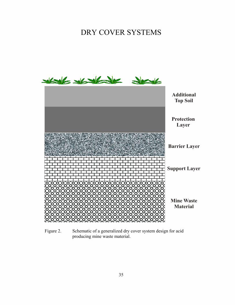
35
Mine WasteMaterial
Support Layer
Barrier Layer
ProtectionLayer
AdditionalTop Soil
Figure 2. Schematic of a generalized dry cover system design for acidproducing mine waste material.
DRY COVER SYSTEMS
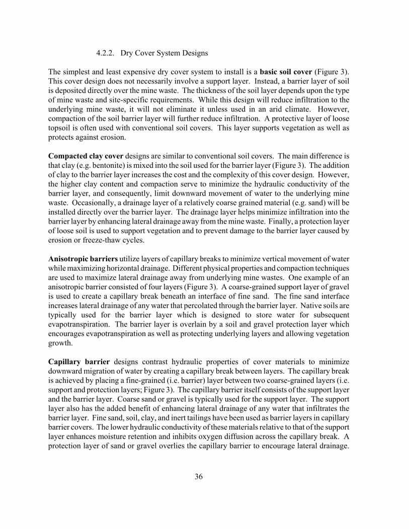
36
4.2.2. Dry Cover System Designs
The simplest and least expensive dry cover system to install is a basic soil cover (Figure 3).This cover design does not necessarily involve a support layer. Instead, a barrier layer of soilis deposited directly over the mine waste. The thickness of the soil layer depends upon the typeof mine waste and site-specific requirements. While this design will reduce infiltration to theunderlying mine waste, it will not eliminate it unless used in an arid climate. However,compaction of the soil barrier layer will further reduce infiltration. A protective layer of loosetopsoil is often used with conventional soil covers. This layer supports vegetation as well asprotects against erosion.
Compacted clay cover designs are similar to conventional soil covers. The main difference isthat clay (e.g. bentonite) is mixed into the soil used for the barrier layer (Figure 3). The additionof clay to the barrier layer increases the cost and the complexity of this cover design. However,the higher clay content and compaction serve to minimize the hydraulic conductivity of thebarrier layer, and consequently, limit downward movement of water to the underlying minewaste. Occasionally, a drainage layer of a relatively coarse grained material (e.g. sand) will beinstalled directly over the barrier layer. The drainage layer helps minimize infiltration into thebarrier layer by enhancing lateral drainage away from the mine waste. Finally, a protection layerof loose soil is used to support vegetation and to prevent damage to the barrier layer caused byerosion or freeze-thaw cycles.
Anisotropic barriers utilize layers of capillary breaks to minimize vertical movement of waterwhile maximizing horizontal drainage. Different physical properties and compaction techniquesare used to maximize lateral drainage away from underlying mine wastes. One example of ananisotropic barrier consisted of four layers (Figure 3). A coarse-grained support layer of gravelis used to create a capillary break beneath an interface of fine sand. The fine sand interfaceincreases lateral drainage of any water that percolated through the barrier layer. Native soils aretypically used for the barrier layer which is designed to store water for subsequentevapotranspiration. The barrier layer is overlain by a soil and gravel protection layer whichencourages evapotranspiration as well as protecting underlying layers and allowing vegetationgrowth.
Capillary barrier designs contrast hydraulic properties of cover materials to minimizedownward migration of water by creating a capillary break between layers. The capillary breakis achieved by placing a fine-grained (i.e. barrier) layer between two coarse-grained layers (i.e.support and protection layers; Figure 3). The capillary barrier itself consists of the support layerand the barrier layer. Coarse sand or gravel is typically used for the support layer. The supportlayer also has the added benefit of enhancing lateral drainage of any water that infiltrates thebarrier layer. Fine sand, soil, clay, and inert tailings have been used as barrier layers in capillarybarrier covers. The lower hydraulic conductivity of these materials relative to that of the supportlayer enhances moisture retention and inhibits oxygen diffusion across the capillary break. Aprotection layer of sand or gravel overlies the capillary barrier to encourage lateral drainage.
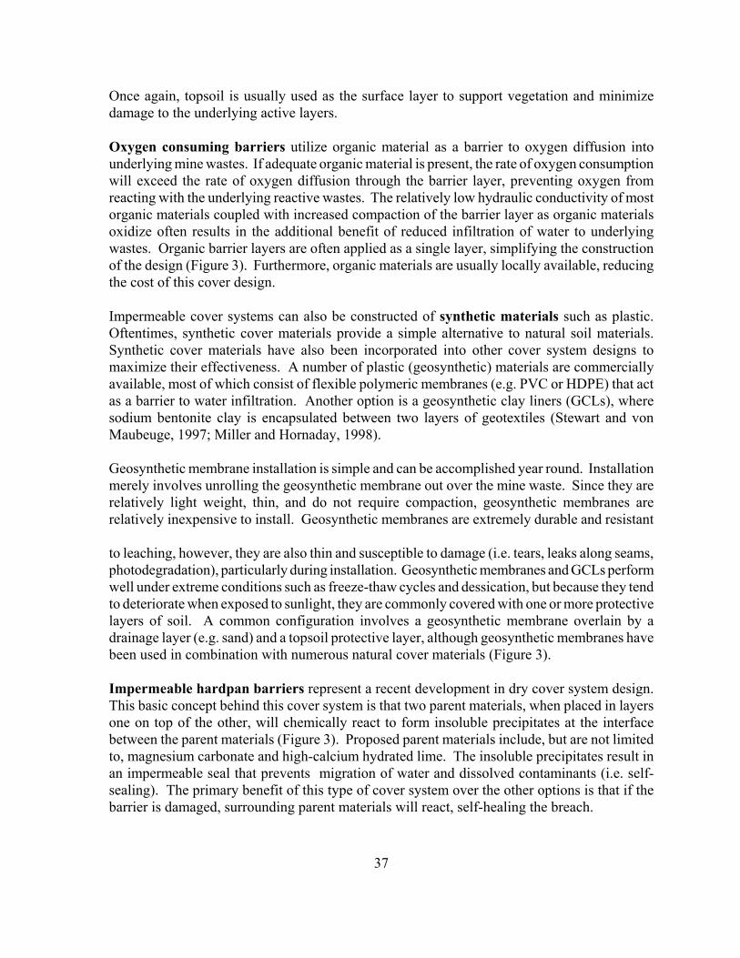
37
Once again, topsoil is usually used as the surface layer to support vegetation and minimizedamage to the underlying active layers.
Oxygen consuming barriers utilize organic material as a barrier to oxygen diffusion intounderlying mine wastes. If adequate organic material is present, the rate of oxygen consumptionwill exceed the rate of oxygen diffusion through the barrier layer, preventing oxygen fromreacting with the underlying reactive wastes. The relatively low hydraulic conductivity of mostorganic materials coupled with increased compaction of the barrier layer as organic materialsoxidize often results in the additional benefit of reduced infiltration of water to underlyingwastes. Organic barrier layers are often applied as a single layer, simplifying the constructionof the design (Figure 3). Furthermore, organic materials are usually locally available, reducingthe cost of this cover design.
Impermeable cover systems can also be constructed of synthetic materials such as plastic.Oftentimes, synthetic cover materials provide a simple alternative to natural soil materials.Synthetic cover materials have also been incorporated into other cover system designs tomaximize their effectiveness. A number of plastic (geosynthetic) materials are commerciallyavailable, most of which consist of flexible polymeric membranes (e.g. PVC or HDPE) that actas a barrier to water infiltration. Another option is a geosynthetic clay liners (GCLs), wheresodium bentonite clay is encapsulated between two layers of geotextiles (Stewart and vonMaubeuge, 1997; Miller and Hornaday, 1998).
Geosynthetic membrane installation is simple and can be accomplished year round. Installationmerely involves unrolling the geosynthetic membrane out over the mine waste. Since they arerelatively light weight, thin, and do not require compaction, geosynthetic membranes arerelatively inexpensive to install. Geosynthetic membranes are extremely durable and resistant
to leaching, however, they are also thin and susceptible to damage (i.e. tears, leaks along seams,photodegradation), particularly during installation. Geosynthetic membranes and GCLs performwell under extreme conditions such as freeze-thaw cycles and dessication, but because they tendto deteriorate when exposed to sunlight, they are commonly covered with one or more protectivelayers of soil. A common configuration involves a geosynthetic membrane overlain by adrainage layer (e.g. sand) and a topsoil protective layer, although geosynthetic membranes havebeen used in combination with numerous natural cover materials (Figure 3).
Impermeable hardpan barriers represent a recent development in dry cover system design.This basic concept behind this cover system is that two parent materials, when placed in layersone on top of the other, will chemically react to form insoluble precipitates at the interfacebetween the parent materials (Figure 3). Proposed parent materials include, but are not limitedto, magnesium carbonate and high-calcium hydrated lime. The insoluble precipitates result inan impermeable seal that prevents migration of water and dissolved contaminants (i.e. self-sealing). The primary benefit of this type of cover system over the other options is that if thebarrier is damaged, surrounding parent materials will react, self-healing the breach.
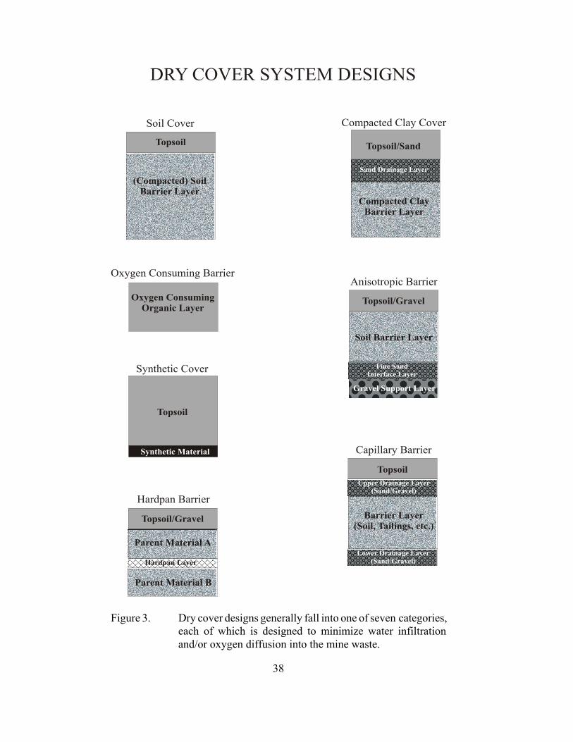
38
DRY COVER SYSTEM DESIGNS
Soil Cover
(Compacted) SoilBarrier Layer
Topsoil
Anisotropic Barrier
Topsoil/Gravel
Gravel Support Layer
Fine SandInterface Layer
Soil Barrier Layer
Capillary Barrier
Upper Drainage Layer(Sand/Gravel)
Topsoil
Lower Drainage Layer(Sand/Gravel)
Barrier Layer(Soil, Tailings, etc.)
Oxygen Consuming Barrier
Oxygen ConsumingOrganic Layer
Synthetic Cover
Topsoil
Synthetic Material
Compacted Clay Cover
Topsoil/Sand
Compacted ClayBarrier Layer
Sand Drainage Layer
Hardpan Barrier
Topsoil/Gravel
Parent Material B
Parent Material A
Hardpan Layer
Figure 3. Dry cover designs generally fall into one of seven categories,each of which is designed to minimize water infiltrationand/or oxygen diffusion into the mine waste.
39
4.2.3 Assessment of Dry Cover System Designs
4.2.3.1. Variables Affecting Dry Cover System Design
The primary issue concerns the type of materials to be used in the dry cover system. Coverrequirements are almost always site-specific, depending on variables such as the physical,chemical and mineralogical properties of the wastes, climatic conditions, local regulations, andavailability of cover materials. Consequently, a cover system implemented at one mine site maynot meet the objectives intended for similar reactive wastes at another site. The choice of covermaterials is often based upon numerous variables including costs, ease of construction, andoverall effectiveness.
4.2.3.2. Predictive Modeling of Dry Cover System Design
How well a proposed dry cover system will perform is usually tested using predictive modeling,and occasionally, laboratory column studies. Predictive models are frequently used to predictthe long-term effectiveness of a cover system, since long-term performance of a specific coversystem cannot be determined prior to installation. Predictive models are typically used to meetone of the following objectives: determine ground water flow through a mine waste mass aswell as over or around it, estimate surface water and precipitation infiltration through the coversystem, and predict the water quality of drainage from the covered mine wastes. The use ofmodels in this way is an inexpensive method to evaluate multiple cover systems and their long-term impacts on local surface and ground water quality in a very short amount of time.
4.2.3.3. Materials Testing
Laboratory tests are typically used to determine the hydraulic and geotechnical properties ofparticular dry cover materials under consideration as well as how layers of multiple covermaterials may interact to reduce infiltration and oxygen diffusion to the underlying waste.Hydraulic conductivity and porosity are the most frequently determined properties. However,D10, specific gravity, plasticity index, and numerous other parameters have been determined aswell. Occasionally, the same parameters will be determined for the mine waste, particularly ifthe mine waste is tailings rather than waste rock. The most thorough studies also determinedthe physical, chemical, and mineralogical properties of potential cover materials and/or the minewaste.
4.2.3.4. Effectiveness of a Dry Cover System Design
The effectiveness of a cover system is typically measured in terms of oxygen concentrations andwater content profiles throughout and beneath the cover. Column experiments are designed withinstrumentation to measure temperature and pressure changes, water content and oxygenconcentrations at regular intervals in the column. Since sulfide oxidation is an exothermicreaction, temperature measurements provide a qualitative indication of the extent to whichoxidation had occurred in the mine waste. Pressure changes were measured using tensiometers
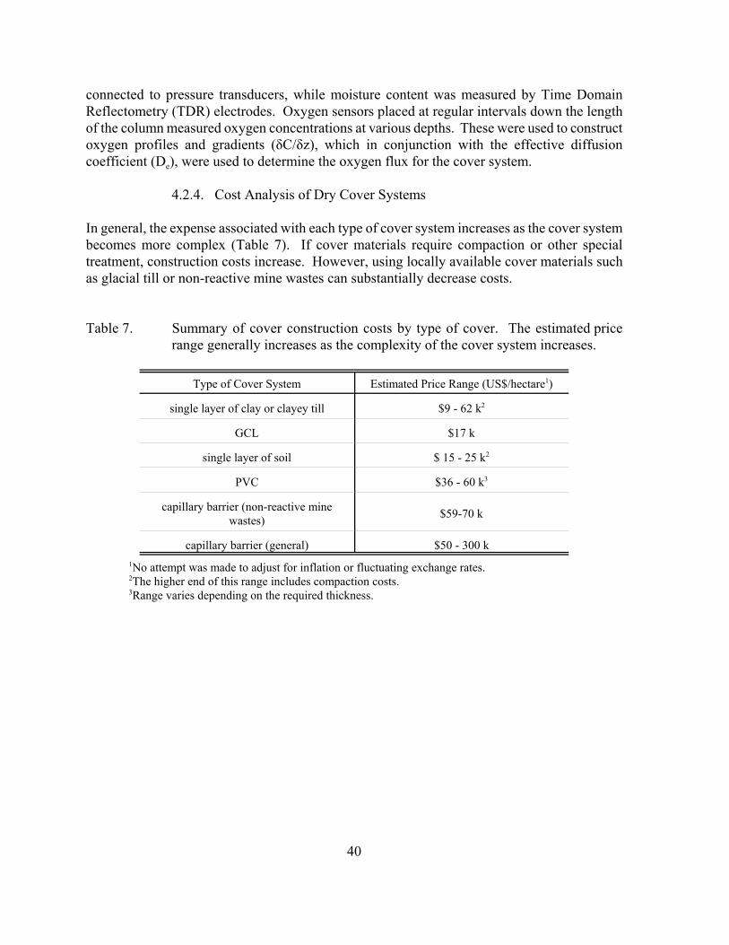
40
connected to pressure transducers, while moisture content was measured by Time DomainReflectometry (TDR) electrodes. Oxygen sensors placed at regular intervals down the lengthof the column measured oxygen concentrations at various depths. These were used to constructoxygen profiles and gradients (δC/δz), which in conjunction with the effective diffusioncoefficient (De), were used to determine the oxygen flux for the cover system.
4.2.4. Cost Analysis of Dry Cover Systems
In general, the expense associated with each type of cover system increases as the cover systembecomes more complex (Table 7). If cover materials require compaction or other specialtreatment, construction costs increase. However, using locally available cover materials suchas glacial till or non-reactive mine wastes can substantially decrease costs.
Table 7. Summary of cover construction costs by type of cover. The estimated pricerange generally increases as the complexity of the cover system increases.
Type of Cover System Estimated Price Range (US$/hectare1)
single layer of clay or clayey till $9 - 62 k2
GCL $17 k
single layer of soil $ 15 - 25 k2
PVC $36 - 60 k3
capillary barrier (non-reactive minewastes) $59-70 k
capillary barrier (general) $50 - 300 k1No attempt was made to adjust for inflation or fluctuating exchange rates.2The higher end of this range includes compaction costs.3Range varies depending on the required thickness.
41
4.2.5. Potential for the Use of Dry Cover Systems for Reactive Mine Wastes inMinnesota
4.2.5.1. Dry Cover Systems Used in Minnesota
Dry cover systems have been shown to limit water infiltration into reactive mine wastes inMinnesota. Simple soil and synthetic cover materials were applied to stockpiled reactive minewastes at LTV Steel Mining Company’s Dunka Mine near Babbitt, Minnesota (Eger andLapakko, 1985; Udoh, 1993). These systems were designed to minimize the amount of drainagefrom the stockpiles rather than prevent drainage acidification.
Six test stockpiles containing 820 to 1300 metric tons of sulfidic mine waste material wereconstructed in 1977 at the AMAX/Kennecott site (Eger and Lapakko, 1985). Three of thestockpiles remained exposed to the atmosphere as controls, and the other three were coveredwith 18-29 cm of soil obtained from a nearby borrow pit in 1978. Stockpile 2 was covered withtopsoil, while piles 3 and 5 were covered with a coarse, sandy soil. However, 30 cm of sandytill was added to the coarse sand on pile 5 in 1980. Revegetation efforts began immediately in1978. There was no flow reduction by the vegetated coarse sand cover (pile 3). The vegetatedcovers of topsoil (pile 2) and combined sandy till over coarse sand (pile 5) both produced runoffcoefficients 30 to 50% less than the control values.
Three different soil cover systems and one synthetic cover were evaluated for their effectivenessat stemming infiltration into sulfidic mine wastes at the Dunka site (Udoh, 1993). The covermaterials under consideration were glacial tills screened to minus 2.5 inches and 0.5 inches,glacial till screened to minus 2.5 inches mixed with 5% bentonite, and a 20-mil PVC membrane.Laboratory tests indicated that the permeability of these materials ranged from 1.55 x 10⁻⁶ cm/s(49 cm/yr) for the glacial till down to 4.12 x 10⁻⁹ cm/s (0.13 cm/yr) for glacial till mixed with5% bentonite, meeting the set standard of 2 x 10⁻⁶ cm/s (63 cm/yr). These results were similarto Hydrologic Evaluation of Landfill Performance (HELP) model simulations that predictedpermeabilities ranging from 2.1 x 10⁻⁶ cm/s (66 cm/yr) for minus 2.5 inches of glacial till downto 5.2 x 10⁻¹⁰ cm/s (0.02 cm/yr) for glacial till mixed with 5% bentonite. The model simulationsalso indicated that the major water loss would be to evapotranspiration. Infiltration waspredicted to be reduced by 34% for glacial till cover, and could be decreased by up to 80% if thecover materials were compacted. Actual field test results showed that infiltration was reducedby 60%, 88%, 89%, and 97% for glacial till screened to minus 2.5 inches, till screened to minus0.5 inches, till screened to minus 2.5 inches mixed with 5% bentonite, and the PVC membrane,respectively.
4.2.5.2. Potential for Capillary Barriers
Cover systems designed to retain moisture within their layers (e.g. capillary barriers), appear tobe well-suited to the climate in northern Minnesota, where most reactive mine wastes are found.Northern Minnesota receives approximately twenty eight inches of precipitation each year, twothirds of which falls between May and September (MN DNR, 2000). This amount of rainfall
42
should be sufficient to maintain a moisture-retaining layer within a capillary barrier. Moisture-retaining layers not only divert infiltration, but also inhibit oxygen transport to the underlyingwaste. These characteristics help minimize the extent of drainage acidification. Laboratory andfield scale studies world-wide have demonstrated the effectiveness of capillary barriers undersimilar climatic conditions.
There are several potential drawbacks to capillary barrier cover systems. First, most operationaldemonstrations of capillary barriers have been on tailings within a basin, where side slopes werenot an issue. Methods to cover side slopes without additional expense must be developed beforeextensive use of capillary barriers on stockpiles is feasible. In practice, capillary barriers maybe better suited for tailings within a basin or covering waste material disposed of in an open pitrather than large stockpiles.
Second, the cost of constructing a capillary barrier cover system may be prohibitive. Sinceseveral layers of different cover materials must be purchased, transported, and put in place,capillary barriers are generally more expensive to construct than simple cover systems. Inpractice, costs are minimized by using locally available materials. For example, local glacialtill is frequently used to construct capillary barriers. However, similar materials are not readilyavailable in northern Minnesota, the third potential drawback. Local alternative materials arelikely to include low or desulfurized tailings. One particularly attractive alternative is taconitetailings, which generally contain very little sulfur and several percent carbonate minerals. It isimportant to note however, that the availability of taconite tailings or any other alternativematerial will be highly site specific.
4.2.5.3. Potential for Organic Cover Systems
Oxygen-consuming organic covers also show potential for preventing acidic drainage fromreactive mine wastes in Minnesota. However, several questions must be addressed beforeorganic cover systems can be used extensively. Two methods of applying organic material toreactive mine wastes have been described in the literature. The first method involves theapplication of successive layers of organic material over reactive wastes throughout the life ofthe disposal operation. Ultimately, this practice results in layering and/or blending of organicand mine waste materials. The second method assumes that operations have ceased and that theorganic material represents the final cover. At this time, it is not entirely clear which of thesemethods would be best suited for Minnesota mine wastes.
Numerous organic materials have been tested in laboratory and field cover systemdemonstrations conducted world-wide. Listed among these materials are forestry wastes, peat,paper residue, and various municipal wastes. Based on demonstrated results reported in theliterature and local availability, paper recycling residues, and possibly municipal wastes, appearto be the most promising organic cover materials in northern Minnesota. Both of these optionsare also attractive in that they use one waste material to contain another.
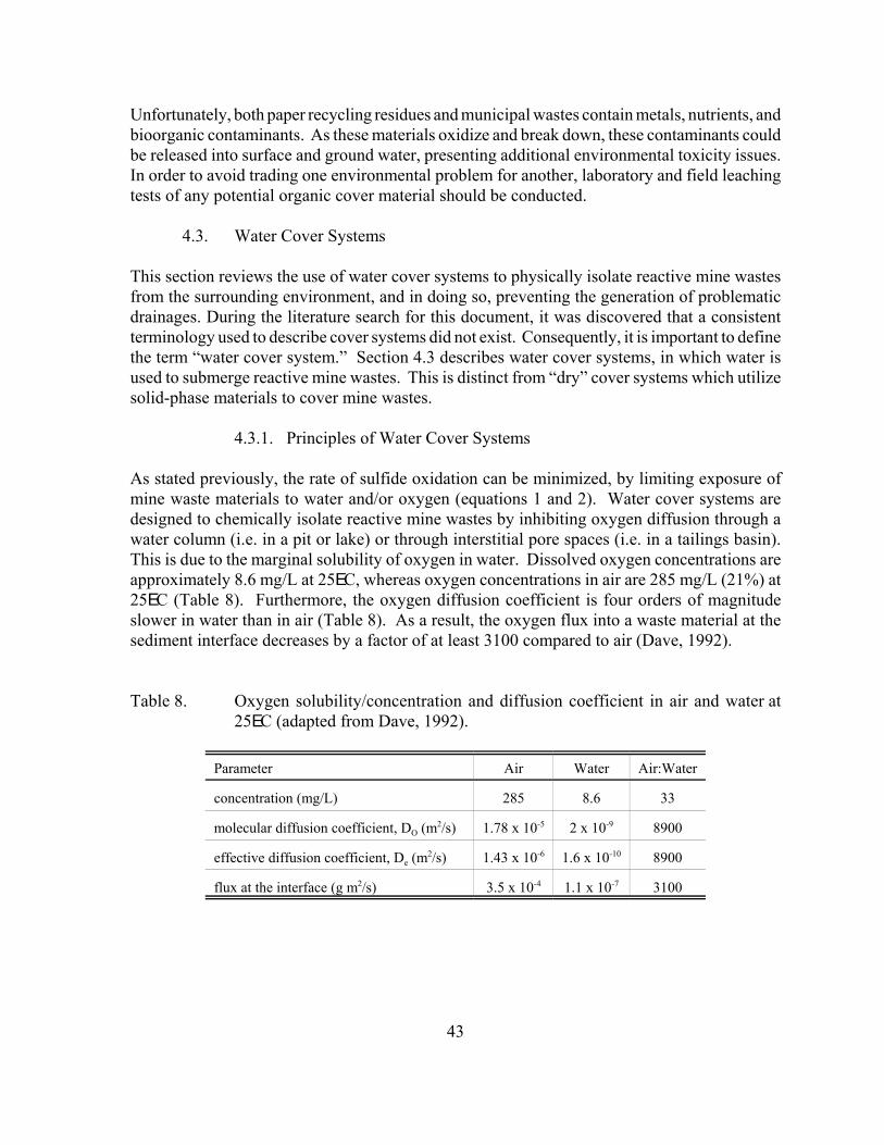
43
Unfortunately, both paper recycling residues and municipal wastes contain metals, nutrients, andbioorganic contaminants. As these materials oxidize and break down, these contaminants couldbe released into surface and ground water, presenting additional environmental toxicity issues.In order to avoid trading one environmental problem for another, laboratory and field leachingtests of any potential organic cover material should be conducted.
4.3. Water Cover Systems
This section reviews the use of water cover systems to physically isolate reactive mine wastesfrom the surrounding environment, and in doing so, preventing the generation of problematicdrainages. During the literature search for this document, it was discovered that a consistentterminology used to describe cover systems did not exist. Consequently, it is important to definethe term “water cover system.” Section 4.3 describes water cover systems, in which water isused to submerge reactive mine wastes. This is distinct from “dry” cover systems which utilizesolid-phase materials to cover mine wastes.
4.3.1. Principles of Water Cover Systems
As stated previously, the rate of sulfide oxidation can be minimized, by limiting exposure ofmine waste materials to water and/or oxygen (equations 1 and 2). Water cover systems aredesigned to chemically isolate reactive mine wastes by inhibiting oxygen diffusion through awater column (i.e. in a pit or lake) or through interstitial pore spaces (i.e. in a tailings basin).This is due to the marginal solubility of oxygen in water. Dissolved oxygen concentrations areapproximately 8.6 mg/L at 25EC, whereas oxygen concentrations in air are 285 mg/L (21%) at25EC (Table 8). Furthermore, the oxygen diffusion coefficient is four orders of magnitudeslower in water than in air (Table 8). As a result, the oxygen flux into a waste material at thesediment interface decreases by a factor of at least 3100 compared to air (Dave, 1992).
Table 8. Oxygen solubility/concentration and diffusion coefficient in air and water at25EC (adapted from Dave, 1992).
Parameter Air Water Air:Water
concentration (mg/L) 285 8.6 33
molecular diffusion coefficient, DO (m2/s) 1.78 x 10⁻⁵ 2 x 10⁻⁹ 8900
effective diffusion coefficient, De (m2/s) 1.43 x 10⁻⁶ 1.6 x 10⁻¹⁰ 8900
flux at the interface (g m2/s) 3.5 x 10⁻⁴ 1.1 x 10⁻⁷ 3100
44
In a theoretical, ideal situation, sulfide oxidation rates can be slowed by placing reactive wastesbeneath a water cover. Although it is unlikely that sulfide oxidation rates would decrease tosuch an extreme extent at an operational scale, the amount of alkalinity required to neutralizeany acid produced due to sulfide oxidation will be lower beneath a water cover than in air.Depending on specific conditions on site, the required alkalinity may be supplied by neutralizingminerals in the waste itself, surrounding rocks, or surface and/or ground water inputs to thesystem. The presence of organic materials (e.g. dissolved organic matter, algae, etc.) is alsobeneficial in that they may further limit the rate of sulfide oxidation by consuming dissolvedoxygen.
4.3.2. Water Cover System Designs
There are two general types of water cover systems: underwater disposal and elevated watertables. Underwater disposal assumes a permanent water cover above the waste material.Simple underwater disposal consists of depositing reactive mine wastes at the bottom of anexisting pit or natural lake. If the pit or lake is deep enough, the water column may becomechemically and/or thermally stratified, resulting in a deep layer of anaerobic water above thewaste. This stratification further isolates waste materials from oxygen.
In some situations, it may be beneficial to place a surface barrier layer of fine-grained,nonreactive material ( clay, sand, soil, till etc.) above the submerged reactive waste. The surfacebarrier layer further inhibits diffusion of oxygen to and may reduce metal release from reactivewastes. Alternatively, organic materials may be used as a surface barrier layer, which promotessulfate reduction and metal sulfide precipitation.
If ground water outflow from the system is a concern, a ground water barrier layer can be placedbelow the reactive waste material. Ground water barriers either block ground water flow (e.g.clay liners), create preferential low resistance flow paths for ground water (e.g. porousenvelopes), or remediate outflow prior to entering ground water (e.g. reactive walls or anoxiclimestone drains). In some situations, surface and ground water barriers may be used to isolatereactive wastes under water.
Elevated water tables involve raising the water table to saturate reactive wastes placed in a pitor tailings basin. In this situation, a ground water gradient often exists. Consequently,infiltrating precipitation and ground water can be expected to flow through the reactive wasteas directed by the gradient. Additional surface and ground water barriers can be incorporatedinto an elevated water table design. Generally speaking, these options are the same as describedfor the case of simple underwater disposal. However, surface barriers designed to reduceinfiltration of precipitation may also be considered.
45
4.3.3. Assessment of Water Cover Systems
4.3.3.1. Variables Affecting the Design of a Water Cover System
Many of the variables affecting water cover design, such as the physical, chemical andmineralogical properties of the wastes, climatic conditions, local regulations, and economics,are identical to those that must be considered when constructing a dry cover. However, watercover designs must also take into account local hydrology, pit, lake, or tailings pond dimensionsand orientation, storage volume requirements, minimum water depth for bed stability, andstructural engineering requirements (Table 9). Each of these variables is site-specific.Consequently, a water cover system designed for one location will not be suitable for any other.
4.3.3.2. Modeling Water Cover Systems
Frequently, a water cover system will be tested for potential success under several different setsof conditions using hydrologic and/or geochemical predictive models. Predictive models arefrequently used to predict the long-term effectiveness of a water cover, since this cannot bedetermined prior to implementation. Predictive hydrologic models are typically used to establishsteady-state flow into or out of the system and future water levels (e.g. in an open pit afterclosure). Predictive geochemical models are used to determine oxygen transport through thecover, sulfide oxidation rates, metal release, and geochemical equilibria in the water column.The use of models in this way is an inexpensive method to evaluate multiple scenarios (e.g.diversion of surface water to or from a water cover) and their long-term impacts on local surfaceand ground water quality in a very short amount of time.
4.3.3.3. Effectiveness of a Water Cover System
The effectiveness of a water cover system is typically measured in terms of water chemistry andtrace metal release into pore waters, the overlying water layer, and surface and ground wateroutflow from the system (if applicable). The ultimate water quality overlying a reactive wastewill ultimately depend upon sediment transport and wave effects, oxygen flux at the water-wasteinterface, the nature of waste-water interaction, rate of sulfide oxidation, diffusion of reactionproducts into the water cover, and dilution or evaporation due to climatic conditions. Each ofthese factors can be estimated using relatively simple numeric models, laboratory experiments,and field observations. Laboratory experiments are generally designed to determine the physicaland/or chemical interactions between reactive wastes and the water cover. They have also beenused to test the effectiveness of various barrier layers (e.g. sand, peat, etc.) at reducing oxidationin reactive wastes placed beneath a water cover. These results are often used as input forpredictive models (see previous section). Field lysimeter studies are conducted to verifylaboratory studies and to demonstrate the effectiveness of these methods under environmentalconditions.
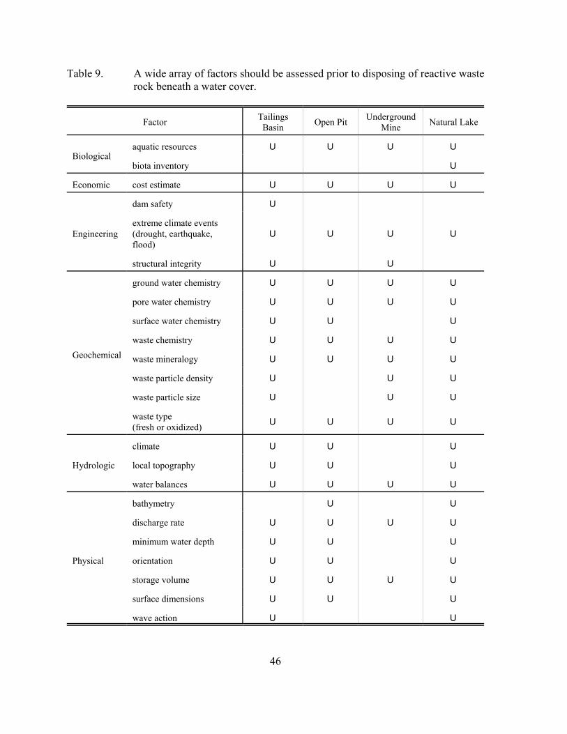
46
Table 9. A wide array of factors should be assessed prior to disposing of reactive wasterock beneath a water cover.
Factor TailingsBasin Open Pit Underground
Mine Natural Lake
Biologicalaquatic resources U U U U
biota inventory U
Economic cost estimate U U U U
Engineering
dam safety U
extreme climate events(drought, earthquake,flood)
U U U U
structural integrity U U
Geochemical
ground water chemistry U U U U
pore water chemistry U U U U
surface water chemistry U U U
waste chemistry U U U U
waste mineralogy U U U U
waste particle density U U U
waste particle size U U U
waste type (fresh or oxidized) U U U U
Hydrologic
climate U U U
local topography U U U
water balances U U U U
Physical
bathymetry U U
discharge rate U U U U
minimum water depth U U U
orientation U U U
storage volume U U U U
surface dimensions U U U
wave action U U
47
4.3.4. Cost Analysis of Water Cover Systems
The expense associated with a water cover system increases as the cover system becomes morecomplex. Construction costs may become an issue if a bottom rock drain or dams must beincluded in the disposal design. Maintaining dams around flooded tailings basins will alsoincrease long-term costs. Even relatively simple disposal of waste materials in an open pit orlake involves transportation of the material to the disposal site. Due to the wide range of watercover system options and site-specific variables, the actual expense of a water cover system mustbe evaluated in terms of the needs and requirements of individual operations.
4.3.5. Water Cover Studies and Potential Use in Minnesota
4.3.5.1. MN DNR Subaqueous Disposal Studies
Water cover systems represent another promising method for preventing acidic drainage fromreactive mine wastes in Minnesota. The MN DNR, Division of Lands and Minerals hasconducted five laboratory experiments and one field experiment to examine the effectivenessof subaqueous disposal and subaqueous disposal with various barrier layers for controlling theoxidation of sulfide minerals present in mine wastes (Lapakko et al., 1998a):
1. Subaqueous disposal tests in the absence of oxygen consuming layers or oxygendiffusion barriers were initially conducted in 2-L Erlenmeyer flasks;2. Subsequent tests were conducted in 2-in.-diameter columns to describe the release ofsulfate as a function of sulfidic mine waste depth for two different mine waste particlesizes;3. In a second phase of the Erlenmeyer flask experiment (#1), composted yard wastewas added to some of these flasks to determine if organic amendments would furtherinhibit oxidation;4. Composted yard waste and fresh rock, as well as controls for compost and rock, weresubjected to subaqueous dissolution in the laboratory;5. A column experiment was conducted to determine the effectiveness of taconitetailings, yard waste compost/tailings mixtures, and limestone layers as potential oxygendiffusion barriers above sulfidic mine wastes; and6. Barriers of tailings, a yard waste compost/tailings mixture, and limestone arepresently under examination in small-scale field tests.
Subaqueous disposal tests in the absence of oxygen consuming layers or oxygen diffusionbarriers were initially conducted in flasks (#1 above) using Virginia Formation hornfels rockcontaining 14% pyrrhotite and in columns (#2 above) using sulfidic Duluth Complex rock(Lapakko et al., 1998). These two experiments revealed that separating sulfidic mine waste fromthe atmosphere with a layer of water would reduce the rate of oxidation of sulfide mineralspresent. However, oxidation would continue and possibly produce acidic waters.
48
Modified subaqueous disposal experiments with barrier layers were conducted in flasks (#3above), beakers (#4 above), and columns (#5 above; Lapakko et al., 1998a). Composted yardwaste was used as an oxygen consuming layer between sulfidic rock and the overlying water inthe flask and beaker tests. Tailings, tailings/yard waste compost mixtures, and limestone wereused as barrier layers in the column tests. In general, the inorganic barrier layers were moreeffective at decreasing sulfide oxidation rates than the compost barriers (MN DNR Hibbinglaboratory, unpublished data). However, it was noted that experimentally determined rates ofacid production averaged roughly 500% higher than theoretical values based on oxygendiffusion through a water column. This is a considerable difference, and should be considereda result of the weekly addition of fresh, oxygen saturated water. The amount of water removedfor sampling and replaced with new water was nearly 5% of the entire column water volume foreach sample. Therefore, the rates of acid production due to pyrrhotite oxidation in thisexperiment are not controlled by the rate of oxygen diffusion, but by the addition of oxygenatedwater to the rock bed.
A field test (#6 above) examining the effectiveness of limestone, tailings and a tailings compostmixture above sulfidic rock in a subaqueous environment is presently in progress at the MNDNR Research Site in Hibbing, MN (Lapakko et al., 1998a). The subaqueous tests are beingconducted in large cylindrical tanks (d = 46-in., h = 11-ft.), fitted with a 30-mil PVC liner. Thetanks were filled to a depth of 48 inches with minus 3/4 inch Duluth Complex rock with sulfurcontents ranging from 0.63 % to 0.69 %. Initial calculations have yielded negative acidproduction rates (MN DNR Hibbing laboratory, unpublished data). The most likely explanationfor this is that the amount of sulfate released due to sulfide oxidation is very small relative tosulfate concentrations already present in the water cover, and therefore, cannot be measuredaccurately.
4.3.5.2. MN DNR Study to Create Wetlands on Reactive Tailings
In addition to subaqueous disposal, the MN DNR, Division of Lands and Minerals has beeninvestigating various strategies to create wetlands on acid and non-acid generating tailings (Egeret al., 2000a,b). This discussion will focus on small-scale field studies conducted on acid-generating tailings at the MN DNR field research facility in Hibbing, MN (Eger et al., 2000a).Acid-generating tailings from a massive zinc sulfide deposit in Winston Lake, Ontario, wereplaced in small cylindrical tanks. Two uncovered controls were established in addition to fivetreatments: 61-cm cover of wetland soil, 61-cm of glacial till, 61-cm of tailings, and two tankswith 71-cm of water. One of the water covers included the aquatic macrophytes: Elodeacanadensis, Potamegeton sp., and Ceratophyllum demersum. Cattails (Typha sp.) were plantedin the tanks with substrate cover. Overall, the wetlands created over acid generating tailingswere effective at preventing acid conditions (pH = 6.0-6.5) and minimizing metal release (Zn= 0.02 - 0.1 mg/L) relative to the “on-land” controls (pH = 3.1-3.2; Zn = 6400-7400 mg/L; Egeret al., 2000a). The authors suggested that successful creation of wetlands in large tailings basinswould require a 60-cm soil cover along the shoreline and establishment of submergentvegetation in the deeper water areas.
49
4.3.5.3. Potential Use of Water Covers in Minnesota
In summary, both of these strategies show promise as mitigative strategies for reactive minewastes in Minnesota. Subaqueous disposal in abandoned open mine pits represents onealternative for water covers. Decades of iron mining in northern Minnesota has left a largenumber of abandoned open mine pits across the Mesabi and Cuyuna Iron Ranges. One optionmay be to backfill reactive mine wastes into selected pit lakes. The advantage of this alternativeis that these pits lie below local ground water tables and fill with surface and ground waternaturally.
However, backfilling open pit lakes with reactive mine waste should be approached cautiously.As open pits fill with water, local ground water gradients can reverse, resulting in ground wateroutflow into local aquifers. Any contamination of water within the pit due to oxidation ofreactive mine waste will be carried into the aquifer, potentially resulting in contamination. Thiswould be particularly disadvantageous, since a large number of communities in northernMinnesota draw drinking water from these aquifers. Consequently, any plan to dispose ofreactive mine wastes within an existing open pit should involve extensive geochemical andhydrologic characterization as well as ground water monitoring to ensure that local watersupplies are protected.
Elevating the local water table and establishing wetlands on reactive tailings represent a secondalternative water cover system. Wetlands have several advantages including the creation of ananoxic zone above reactive wastes, accumulation of decaying organic matter provides additionalsubstrate to improve growth, and fits with reclamation goals aimed at restoring wetlands inmining areas.
4.4. References on Physical Isolation of Reactive Mine Wastes
Ahmed, S.M. 1994. Surface chemical methods of forming hardpan in pyrrhotite tailings andprevention of the acid mine drainage. In: Internat. Land Reclamation and Mine Drainage Conf.and 3rd Internat. Conf. on the Abatement of Acidic Drainage, Pittsburgh, PA, April 24-29, 2, pg57-66
Ahmed, S.M. 1995. Chemistry of pyrrhotite hardpan formation. In: Mining and theEnvironment Conf. Proc., Sudbury, ON, May 28-June 1, 1, pg 171-180.
Aubertin, M., Bussiere, B., Barbera, J.M., Chapuis, R.P., Monzon, M., Aachib, M. 1997a.Construction and instrumentation of in-situ test plots to evaluate covers built with clean tailings.In: Proc. 4th Internat. Conf. on Acid Rock Drainage (ICARD), Vancouver, British Columbia,May 31-June 6, 2, pg 715-730.
Aubertin, M., Chapuis, R.P., Bouchentouf, A., Bussiere, B. 1997b. Unsaturated flow modelingof inclined layers for the analysis of covers. In: Proc. 4th Internat. Conf. on Acid Rock Drainage(ICARD), Vancouver, British Columbia, May 31-June 6, 2, pg 731-746.
50
Aziz, M.L.; Ferguson, K.D., 1997. Equity silver mine- integrated case study. In: Proc. 4th
Internat. Conf. on Acid Rock Drainage (ICARD), Vancouver, British Columbia, May 31-June6, 1, pg 181-196.
Bell, A.V., Riley, M.D., Yanful, E.K. 1994. Evaluation of a composite soil cover to control acidwaste rock pile drainage. In: Internat. Land Reclamation and Mine Drainage Conf. and 3rd
Internat. Conf. on the Abatement of Acidic Drainage, Pittsburgh, PA, April 24-29, 2, pg 113-121.
Benzaazoua, M., Bussiere, B., Nicholson, R.V., Bernier, L. 1998. Geochemical behavior of amulti-layered cover composed of desulfurized mine tailings. In: Proc. 5th Internat. Conf. onTailings and Mine Waste ‘98, Fort Collins, CO, USA, Jan. 26-28, A.A. Balkema, Rotterdam,Netherlands, 968 p.
Boorman, R.S.; Watson, D.M. 1976. Chemical processes in abandoned sulphide tailings dumpsand environmental implications for northeastern New Brunswick. CIM Bulletin, August, pg 86-96.
Brennecke, D.F.; Corser, P.G. 1998. Performance issues related to geosynthetic liners atMonticello, Utah. In: Proc. 5th Internat. Conf. on Tailings and Mine Waste ‘98, Fort Collins,CO, USA, Jan. 26-28, A.A. Balkema, Rotterdam, Netherlands, 968 p.
Brown, R. 1989. Water management at Brenda Mines. In Proc. of the Thirteenth Annual BritishColumbia Mine Reclamation Symposium, Vernon, British Columbia, June 7-9,1989, pg 8-17.
Bussiere, B., Nicholson, R.V., Aubertin, M., Servant, S. 1997. Effectiveness of covers built withdesulfurized tailings: column tests investigation. In: Proc. 4th Internat. Conf. on Acid RockDrainage (ICARD), Vancouver, British Columbia, May 31-June 6, 2, pg 763-778.
Cabral, A.; Burnotte, F.; Lefebvre, G.; Amyot, G.; Lacassa, G. 1999. Design construction andmonitoring of a waste rock cover using pulp and paper residues. In: Proc. 6th Internat. Conf. onTailings and Mine Waste ‘99, Fort Collins, CO, USA, Jan. 24-27, A.A. Balkema, Rotterdam,Netherlands, 808 p.
Cabral, A.; Lefebvre, G.; Burnotte, F.; Proulx, M.F.; Racine, I.; Audet, C. 1998. Developmentsin the use of deinking residues in cover systems for mine tailings. In: Proc. 5th Internat. Conf.on Tailings and Mine Waste ‘98, Fort Collins, CO, USA, Jan. 26-28, A.A. Balkema, Rotterdam,Netherlands, 968 p.
Cabral, A.; Lefebvre, G.; Proulx, M.F.; Audet, C.; Labbe, M.; Michaud, C. 1997. Use ofdeinking residues as cover material in the prevention of AMD generation at an abandoned minesite. In: Proc. 4th Internat. Conf. on Tailings and Mine Waste ‘97, Fort Collins, CO, USA, Jan.13-17, A.A. Balkema, Rotterdam, Netherlands, 788 p.
51
Catalan, L.J.J.; Yanful, E.K.; Boucher, J.F.; Shelp, M.L. 2000. A field investigation of tailingsresuspension in a shallow water cover. In: Proc. of the 5th Internat. Conf. on Acid RockDrainage (ICARD), Denver, CO, May 21-24, 2, pg 921-931.
Chermak, J.A.; Runnells, D.D. 1997. Development of chemical caps in acid rock drainageenvironments. Mining Engineering, pg 96-97.
Chtaini, A.; Bellaloui, A; Ballivy, G.; Narasiah, S.; Lalancette, J.; Bilodeau, C. 1997. A studyof acid mine drainage control by addition of a alkaline mill paper waste. In: Proc. 4th Internat.Conf. on Acid Rock Drainage (ICARD), Vancouver, British Columbia, May 31-June 6, 3, pg1145-1162.
Crusius, J.; Dunbar, D.; McNee, J.J. 2001. Predictions of pit lake water column properties usinga coupled mixing and geochemical speciation model. SME Annual Meeting, Denver, CO, Feb26-28, Preprint 01-165.
Dave, N.K., 1992. Water cover on acid generating mine/mill wastes: A technical review.CANMET, Project # 30.14.99, 118 p.
Day, S.; Flemming, A.; Demchuk, J. 2000. Waste management planning at the Telkwa CoalProject, Telkwa, British Columbia. In: Proc. of the 5th Internat. Conf. on Acid Rock Drainage(ICARD), Denver, CO, May 21-24, 2, pg 769-777.
Delaney, T.; Hockley, D.; Sollner, D. 1997. Applications of methods for delaying the onset ofacidic drainage. In: Proc. 4th Internat. Conf. on Acid Rock Drainage (ICARD), Vancouver,British Columbia, May 31-June 6, 2, pg 795-810.
De Vos, K.; Barone, F.; Hall, G.; Blowes, D. 2000. Management of water quality in a floodedtailings impoundment. In: Proc. of the 5th Internat. Conf. on Acid Rock Drainage (ICARD),Denver, CO, May 21-24, 2, pg 933-942.
Eger, P; Antonson, D.; Folman, J.; Wagner, J. Melchert, G. 2000a. Creating wetlands on acid-generating tailings; an alternative to encapsulation. MN Dept. Nat. Resour., Div. of Lands andMinerals, St. Paul, MN. 33 p. plus appendices.
Eger, P; Johnson, A.; Melchert, G.; Antonson, D.; Dewar, S. 2000b. The use of dredge materialas an organic substrate to create wetlands in taconite tailings basins. MN Dept. Nat. Resour.,Div. of Lands and Minerals, St. Paul, MN. 54 p. plus appendices.
Eger, A.P., Lapakko, K.A. 1985. Heavy metals study progress report on the field leaching andreclamation program: 1977-1983. MN Dept. Nat. Resour., Div. of Minerals, St. Paul, MN. 53p. plus appendices.
52
Elliott, L.C.M., Liu, L., Stogran, S.W. 1997a. Organic cover materials for tailings: do they meetthe requirements of an effective long term cover? In: Proc. 4th Internat. Conf. on Acid RockDrainage (ICARD), Vancouver, British Columbia, May 31-June 6, 2, pg 811-824.
Elliott, L.C.M., Liu, L., Stogran, S.W. 1997b. Evaluation of single layer organic and inorganiccover materials for oxidized tailings. In: Proc. 4th Internat. Conf. on Tailings and Mine Waste‘97, Fort Collins, CO, USA, Jan. 13-17, A.A. Balkema, Rotterdam, Netherlands, 788 p.
Ettner, D.C.; Brasstad, G. 1999. Induced hardpan formation in a historic tailings impoundment,Roros, Norway. In: Proc. 6th Internat. Conf. on Tailings and Mine Waste ‘99, Fort Collins, CO,USA, Jan. 24-27, A.A. Balkema, Rotterdam, Netherlands, 808 p.
Ganguli, R.; Wilson, T.E.; Bandopadhyay, S. 2001. STADES: an expert system for marinedisposal of mine tailings. SME Annual Meeting, Denver, CO, Feb 26-28, Preprint 01-11.
Gardiner, R.T., Dawson, B.B., Gibson, G.G. 1997. Application of ard abatement technology inreclamation of tailing ponds at Cominco Ltd., Sullivan Mine. In: Proc. 4th Internat. Conf. onAcid Rock Drainage (ICARD), Vancouver, British Columbia, May 31-June 6, 1, pg 47-64.
Germain, D.; Tasse, N.; Dufour, C. 2000. A novel treatment for acid mine drainage using awood-waste cover preventing sulfide oxidation. In: Proc. of the 5th Internat. Conf. on AcidRock Drainage (ICARD), Denver, CO, May 21-24, 2, pg 987-998.
Hanselman, K.; Courtin, G.M. 1999. Effect of different cover, cover/tailings mixes andcapillary breaks on water dynamics within tailings and paper waste cover materials. In: Miningand the Environment Conf. Proc., Sudbury, Ontario, Sept. 13-17, 2, pg 801-810.
Kowalewski, P.E.; Dorey, R.; Wilson, G.W.; Duckett, R. 1998. Tailings impoundmentreclamation soil cover design at the Ridgeway Mine. In: Proc. 5th Internat. Conf. on Tailingsand Mine Waste ‘98, Fort Collins, CO, USA, Jan. 26-28, A.A. Balkema, Rotterdam,Netherlands, 968 p.
Lapakko, K.; Antonson, D.; Jakel, E. 1998a. Mine waste characterization and drainagemitigation: Research summary 1998. MN Dept. Nat. Resour., Division of Minerals, Saint Paul,MN. 50 p.
Lewis, B.A.; Gallinger, R.D.; Wiber, M. 2000. Poirier Site reclamation program. In: Proc. ofthe 5th Internat. Conf. on Acid Rock Drainage (ICARD), Denver, CO, May 21-24, 2, pg 959-968.
Li, M.; Catalan, L.J.J.; St-Germain, P. 2000. Rates of oxygen consumption by sulphidic tailingsunder shallow water covers - field measurements and modelling. In: Proc. of the 5th Internat.Conf. on Acid Rock Drainage (ICARD), Denver, CO, May 21-24, 2, pg 913-920.
53
Lin, Z.; Herbert, R.B. Jr. 1997. Formation of Fe precipitated layers in a mill-tailings deposit:barriers to metal mobilization. In: Proc. 4th Internat. Conf. on Tailings and Mine Waste ‘97,Fort Collins, CO, USA, Jan. 13-17, A.A. Balkema, Rotterdam, Netherlands, 788 p.
Lindvall, M., Lindahl, L.A., Ericsson. 1997. The reclamation project at Saxberget Mine,Sweden. In: Proc. 4th Internat. Conf. on Acid Rock Drainage (ICARD), Vancouver, BritishColumbia, May 31-June 6, 3, pg 1389-1400.
McGregor, R.G.; Stegemann, J.A.; van der Sloot, H.A. 1997. Preliminary results of a field studyof a self-sealing/self-healing cover system. In: Proc. 4th Internat. Conf. on Acid Rock Drainage(ICARD), Vancouver, British Columbia, May 31-June 6, 3, pg 1435-1450.
Miller, B., Hornaday, C. 1998. Geosynthetic clay liners for the mining industry. In: Proc. 5th
Internat. Conf. on Tailings and Mine Waste ‘98, Fort Collins, CO, USA, Jan. 26-28, A.A.Balkema, Rotterdam, Netherlands, 968 p.
MN DNR, 2000. DNR Waters, Climate of Minnesota. URL: http: // www.dnr.state.mn.us/waters /climate /index.html.
Morin, K.A.; Hutt, N.M. 2000. Relocation and submergence of net-acid-generating waste rockfor control of acidic drainage: a case study. In: Proc. of the 5th Internat. Conf. on Acid RockDrainage (ICARD), Denver, CO, May 21-24, 2, pg 819-825.
Nicholson, R.V., Akindunni, F.F., Sydor, R.C., Gillham, R.W. 1991. Saturated tailings coversabove the water table: the physics and criteria for design. Proc. 2nd International Conference onthe Abatement of Acidic Drainage, Montreal, Canada, Sept.16-18, 1, pg 443-460.
Nicholson, R.V., Elberling, B., Williams, G. 1995. A New oxygen consumption technique toprovide rapid assessment of tailings reactivity in the field and the laboratory. In: Mining andthe Environment Conf. Proc., Sudbury, ON, May 28-June 1, 3, pg 999-1006.
Nicholson, R.V., Gillham, R.W., Cherry, J.A., Reardon, E.J. 1989. Reduction of acid generationin mine tailings through the use of moisture-retaining cover layers as oxygen barriers. Can.Geotech. J., 26, pg 1-8.
Nicholson, R.V.; Rinker, M.J. 2000. Metal leaching from sulfide mine waste under neutral pHconditions. In: Proc. of the 5th Internat. Conf. on Acid Rock Drainage (ICARD), Denver, CO,May 21-24, 2, pg 951-957.
O’Kane, M., Wilson, G.W., Barbour, S.L., Swanson, D.A. 1995. Aspects on the performanceof the till cover system at Equity Silver Mines Ltd. In: Mining and the Environment Conf.Proc., Sudbury, ON, May 28-June 1, 2, pg 565-574.
54
O’Kane, M., Perterfield, D., Endersby, M., Haug, M.D. 1998. The design and implementationof the field test plots at BHP Iron Ore, Mt Whaleback-a cover system for an arid climate. SMEAnnual Meeting, Preprint 98-70.
Ricard, J.F., Aubertin, M., Firlotte, F.W., Knapp, R., McMullen, J., Julien, M. 1997. Design andconstruction of a dry cover made of tailings for the closure of Les Terains Auriferes Site,Malartic, Quebec, Canada. In: Proc. 4th Internat. Conf. on Acid Rock Drainage (ICARD),Vancouver, British Columbia, May 31-June 6, 4, pg 1515-1530.
Sevick, G.W., Paruvakat, N., Black, K.P., Hockley, D. 1998. Engineered upland sulfide tailingsmanagement facility. In: Proc. 5th Internat. Conf. on Tailings and Mine Waste ‘98, Fort Collins,CO, USA, Jan. 26-28, A.A. Balkema, Rotterdam, Netherlands, 968 p.
Shay, D.A.; Cellan, R.R. 2000. Acid remediation at Homestake’s Santa Fe Mine using achemical cap. Proc. 2000 Billings Land Reclamation Symposium, March 20-24, Billings, MT.CD-ROM.
Shuri, F.S., Brown, M.L., Schumacher P.M. 1998. Design of the tailings disposal facilities forBattle Mountain Gold Company's Crown Jewel Mine near Oroville, Washington. In: Proc. 5th
Internat. Conf. on Tailings and Mine Waste ‘98, Fort Collins, CO, USA, Jan. 26-28, A.A.Balkema, Rotterdam, Netherlands, 968 p.
Stewart, D., vonMaubeuge, K. 1997. Cost effective and efficient solutions with geosyntheticclay liners for sealing applications in the mining industry. In: Proc. 4th Internat. Conf. onTailings and Mine Waste ‘97, Fort Collins, CO, USA, Jan. 13-17, A.A. Balkema, Rotterdam,Netherlands, 788 p.
Stogran, S.W.; Wiseman, M.E. 1995. A comparison of organic and inorganic covers for longterm prevention or amelioration of acid mine drainage. In: Mining and the Environment Conf.Proc., Sudbury, ON, May 28-June 1, 2, pg 555-564.
Tasse, N. 1999. Long term efficiency of wood waste covers: Indications from pore gascompositions. In: Mining and the Environment Conf. Proc., Sudbury, Ontario, Sept. 13-17, 2,pg 655-660.
Tasse, N. 2000. Efficient prevention of sulfide oxidation by an organic cover: For how long cana reactive barrier be reactive? In: Proc. of the 5th Internat. Conf. on Acid Rock Drainage(ICARD), Denver, CO, May 21-24, 2, pg 979-986.
Tasse, N., Germain, D., Dufour, C., Tremblay, R. 1997a. Organic-waste cover over the East Sullivan mine tailings: beyond the oxygen barrier. In: Proc. 4th Internat. Conf. on Acid RockDrainage (ICARD), Vancouver, British Columbia, May 31-June 6, 4, pg 1627-1642.
55
Tasse, N.; Germain, D.; Dufour, C.; Tremblay, R. 1997b. Hard-pan formation in the CanadianMalartic mine tailings: implication for the reclamation of the abandoned impoundment. In:Proc. 4th Internat. Conf. on Acid Rock Drainage (ICARD), Vancouver, British Columbia, May31-June 6, 4, pg 1797-1812.
Udoh, F.D. 1993. Minimization of infiltration into mining stockpiles using low permeabilitycovers. PhD thesis, University of Wisconsin, Madison, WI. 121p.
Williams, D.J., Wilson, G.W., Currey, N.A. 1997. A cover system for a potentially acid formingwaste rock dump in a dry climate. In: Proc. 4th Internat. Conf. on Tailings and Mine Waste ‘97,Fort Collins, CO, USA, Jan. 13-17, A.A. Balkema, Rotterdam, Netherlands, 788 p.
Wilson, G.W., Newman, L., Barbour, S.L. 1997. The cover research program at Equity SilverMine Ltd. Proc. In: Proc. 4th Internat. Conf. on Acid Rock Drainage (ICARD), Vancouver,British Columbia, May 31-June 6, 1, pg 197-210.
Woyshner, M.R., St Arneault, C., St Arnaud, L.C. 1997. Five years after covering tailings andwaste rock with a composite soil cover: a case review and water quality predictions at theMillenbach Site near Rouyn-Noranda, Quebec. In: Proc. 4th Internat. Conf. on Acid RockDrainage (ICARD), Vancouver, British Columbia, May 31-June 6, 4, pg 1673-1690.
Woyshner, M.R., Swarbrick, B. 1997. First year findings from soil cover test plots on KiddCreek thickened tailings near Timmins, Ontario. In: Proc. 4th Internat. Conf. on Acid RockDrainage (ICARD), Vancouver, British Columbia, May 31-June 6, 3, pg 1075-1092.
Yanful, E.K. 1991. Engineered soil covers for reactive tailings management: theoretical conceptsand laboratory development. Proc. 2nd International Conference on the Abatement of AcidicDrainage, Montreal, Canada, Sept.16-18, 1, pg 461-486.
Yanful, E.K. 1993. Oxygen diffusion through soil covers on sulfidic mine tailings. J. Geotech.Eng., 119, 8, pg 1207-28.
Yanful, E.K., St-Arnaud, L.C. 1991. Design, instrumentation, and construction of engineeredsoil covers for reactive tailings management. Proc. 2nd International Conference on theAbatement of Acidic Drainage, Montreal, Canada, Sept.16-18, 1, pg 487-504.
Yanful, E.K., Bell, A.V., Woyshner, M.R. 1993a. Design of a composite soil cover for anexperimental waste rock pile near Newcastle, New Brunswick, Canada. Can. Geotech. J., 30, pg578-587.
Yanful, E.K., Riley, M.D., Woyshner, M.R., Duncan, J. 1993b. Construction and monitoring ofa composite soil cover on an experimental waste-rock pile near Newcastle, New Brunswick,Canada. Can. Geotech. J., 30, pg 588-599.
56
Yanful, E.K., Aube, B.C., Woyshner, M., St-Arnaud, L.C. 1994. Field and laboratoryperformance of engineered covers on the Waite Amulet tailings. In: Internat. Land Reclamationand Mine Drainage Conf. and 3rd Internat. Conf. on the Abatement of Acidic Drainage,Pittsburgh, PA, April 24-29, 2, pg 138-147.
Zahn, G.; Aubertin, M.; Mayer, A.; Burke, K.; McMullen, J. 2001. Capillary cover design forleach pad closure. SME Annual Meeting, Denver, CO, Feb 26-28, Preprint 01-137.
Zhixun, L.; Herbert Jr., R.B. 1997. Formation of Fe precipitated layers in a mill-tailings deposit:Barriers to metal mobilization. In: Proc. 4th Internat. Conf. on Tailings and Mine Waste ‘97,Fort Collins, CO, USA, Jan. 13-17, A.A. Balkema, Rotterdam, Netherlands, 788 p.
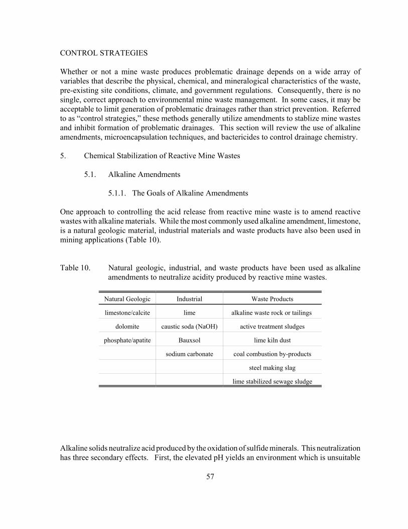
57
CONTROL STRATEGIES
Whether or not a mine waste produces problematic drainage depends on a wide array ofvariables that describe the physical, chemical, and mineralogical characteristics of the waste,pre-existing site conditions, climate, and government regulations. Consequently, there is nosingle, correct approach to environmental mine waste management. In some cases, it may beacceptable to limit generation of problematic drainages rather than strict prevention. Referredto as “control strategies,” these methods generally utilize amendments to stablize mine wastesand inhibit formation of problematic drainages. This section will review the use of alkalineamendments, microencapsulation techniques, and bactericides to control drainage chemistry.
5. Chemical Stabilization of Reactive Mine Wastes
5.1. Alkaline Amendments
5.1.1. The Goals of Alkaline Amendments
One approach to controlling the acid release from reactive mine waste is to amend reactivewastes with alkaline materials. While the most commonly used alkaline amendment, limestone,is a natural geologic material, industrial materials and waste products have also been used inmining applications (Table 10).
Table 10. Natural geologic, industrial, and waste products have been used as alkalineamendments to neutralize acidity produced by reactive mine wastes.
Natural Geologic Industrial Waste Products
limestone/calcite lime alkaline waste rock or tailings
dolomite caustic soda (NaOH) active treatment sludges
phosphate/apatite Bauxsol lime kiln dust
sodium carbonate coal combustion by-products
steel making slag
lime stabilized sewage sludge
Alkaline solids neutralize acid produced by the oxidation of sulfide minerals. This neutralizationhas three secondary effects. First, the elevated pH yields an environment which is unsuitable
58
for Thiobacillus ferrooxidans, a strain of bacteria which catalyzes sulfide mineral oxidation.The elimination of these bacteria limits the rate of sulfide oxidation, and therefore, the rate ofacid production. Second, the elevated pH enhances the oxidation of ferrous iron and thesubsequent precipitation of ferric oxyhydroxides. If the pH is elevated in the immediateneighborhood of iron sulfide mineral surfaces, precipitates will form on the mineral surface.This would impede chemical transport to and from the iron sulfide mineral surface, andconsequently, inhibit iron sulfide oxidation and the attendant acid production. Third, as pHincreases the equilibrium concentrations of trace metals decrease. The decrease in trace metalconcentrations is due to increased precipitation (as hydroxides, oxides, and/or carbonates) andadsorption.
An important factor in the balance between acid production and acid neutralization is the relativemasses of the iron sulfide and calcium and magnesium carbonate minerals. The alkaline dosagerequirement can be estimated based on theory or empirical evidence. The theoretical alkalinityrequirement can be calculated assuming that each mole of sulfur produces two moles of acid andthat each mole of calcium carbonate equivalent consumes two moles of acid. Calculation of theacid-producing sulfur content should be based on sulfur associated with iron sulfide minerals.
5.1.2. Assessment of Alkaline Amendment Effectiveness
The effectiveness of an alkaline amendment is measured in terms of the quality of water drainingfrom the mine waste. This is usually determined in terms of drainage pH, acidity, and chemicalrelease (e.g. sulfate and trace metals). In other words, a successful amendment will result innear-neutral drainage pH with low levels of sulfate and trace metals.
Laboratory studies on alkaline amendments are typically conducted in columns, where reactivewaste rock or tailings are mixed with alkaline material (e.g. limestone, lime, fly ash, etc.).Alkaline loadings are geochemically determined by the acid producing potential (AP) of thewaste material and the neutralization potential (NP) of the alkaline amendment. Although awide range of NP to AP ratios have been tested, those in the range of 1:1 to 2:1 tend totemporarily neutralize acid produced due to sulfide oxidation (Day, 1994; Stewart et al., 1994;Lapakko et al., 1997, 2000).
5.1.3. Cost Analysis of Adding Alkaline Materials to Reactive Mine Wastes
The actual cost involved with amending reactive mine wastes with alkaline material varieswidely depending on the type of alkaline material used, application ratio, and accessibility of thelocation. Chemical costs tend to be low, ranging from zero to tens of dollars per ton (Table 11).Waste alkaline materials, such as fly ash, are the least expensive and are usually free.
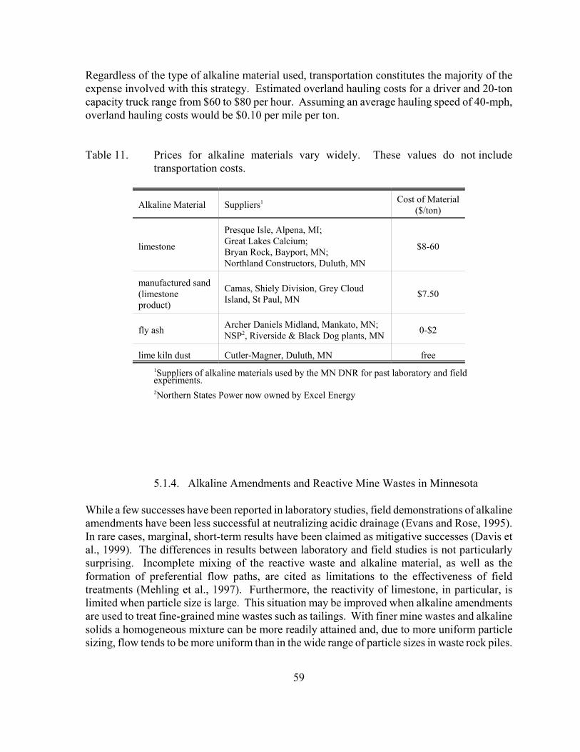
59
Regardless of the type of alkaline material used, transportation constitutes the majority of theexpense involved with this strategy. Estimated overland hauling costs for a driver and 20-toncapacity truck range from $60 to $80 per hour. Assuming an average hauling speed of 40-mph,overland hauling costs would be $0.10 per mile per ton.
Table 11. Prices for alkaline materials vary widely. These values do not includetransportation costs.
Alkaline Material Suppliers1 Cost of Material($/ton)
limestone
Presque Isle, Alpena, MI;Great Lakes Calcium;Bryan Rock, Bayport, MN;Northland Constructors, Duluth, MN
$8-60
manufactured sand(limestoneproduct)
Camas, Shiely Division, Grey CloudIsland, St Paul, MN $7.50
fly ash Archer Daniels Midland, Mankato, MN;NSP2, Riverside & Black Dog plants, MN 0-$2
lime kiln dust Cutler-Magner, Duluth, MN free1Suppliers of alkaline materials used by the MN DNR for past laboratory and field experiments.2Northern States Power now owned by Excel Energy
5.1.4. Alkaline Amendments and Reactive Mine Wastes in Minnesota
While a few successes have been reported in laboratory studies, field demonstrations of alkalineamendments have been less successful at neutralizing acidic drainage (Evans and Rose, 1995).In rare cases, marginal, short-term results have been claimed as mitigative successes (Davis etal., 1999). The differences in results between laboratory and field studies is not particularlysurprising. Incomplete mixing of the reactive waste and alkaline material, as well as theformation of preferential flow paths, are cited as limitations to the effectiveness of fieldtreatments (Mehling et al., 1997). Furthermore, the reactivity of limestone, in particular, islimited when particle size is large. This situation may be improved when alkaline amendmentsare used to treat fine-grained mine wastes such as tailings. With finer mine wastes and alkalinesolids a homogeneous mixture can be more readily attained and, due to more uniform particlesizing, flow tends to be more uniform than in the wide range of particle sizes in waste rock piles.
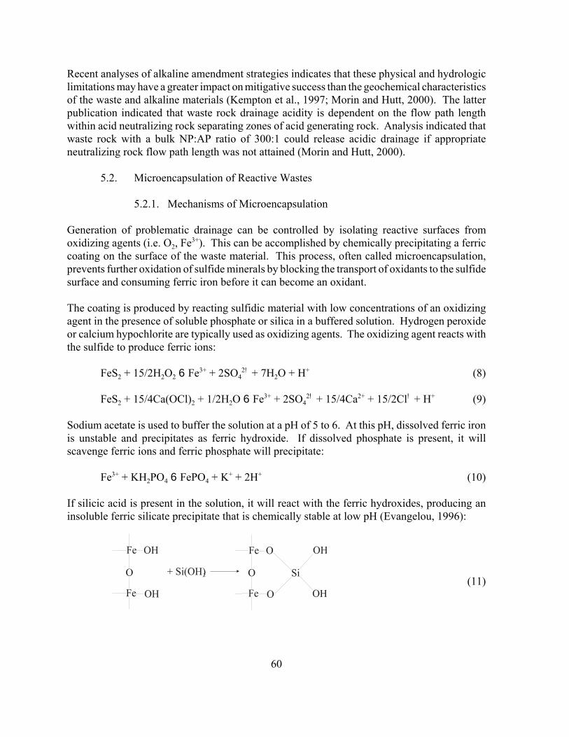
60
Recent analyses of alkaline amendment strategies indicates that these physical and hydrologiclimitations may have a greater impact on mitigative success than the geochemical characteristicsof the waste and alkaline materials (Kempton et al., 1997; Morin and Hutt, 2000). The latterpublication indicated that waste rock drainage acidity is dependent on the flow path lengthwithin acid neutralizing rock separating zones of acid generating rock. Analysis indicated thatwaste rock with a bulk NP:AP ratio of 300:1 could release acidic drainage if appropriateneutralizing rock flow path length was not attained (Morin and Hutt, 2000).
5.2. Microencapsulation of Reactive Wastes
5.2.1. Mechanisms of Microencapsulation
Generation of problematic drainage can be controlled by isolating reactive surfaces fromoxidizing agents (i.e. O2, Fe3+). This can be accomplished by chemically precipitating a ferriccoating on the surface of the waste material. This process, often called microencapsulation,prevents further oxidation of sulfide minerals by blocking the transport of oxidants to the sulfidesurface and consuming ferric iron before it can become an oxidant.
The coating is produced by reacting sulfidic material with low concentrations of an oxidizingagent in the presence of soluble phosphate or silica in a buffered solution. Hydrogen peroxideor calcium hypochlorite are typically used as oxidizing agents. The oxidizing agent reacts withthe sulfide to produce ferric ions:
FeS2 + 15/2H2O2 6 Fe3+ + 2SO42! + 7H2O + H+ (8)
FeS2 + 15/4Ca(OCl)2 + 1/2H2O 6 Fe3+ + 2SO42! + 15/4Ca2+ + 15/2Cl! + H+ (9)
Sodium acetate is used to buffer the solution at a pH of 5 to 6. At this pH, dissolved ferric ironis unstable and precipitates as ferric hydroxide. If dissolved phosphate is present, it willscavenge ferric ions and ferric phosphate will precipitate:
Fe3+ + KH2PO4 6 FePO4 + K+ + 2H+ (10)
If silicic acid is present in the solution, it will react with the ferric hydroxides, producing aninsoluble ferric silicate precipitate that is chemically stable at low pH (Evangelou, 1996):
(11)
61
Silicate coatings are generally considered more “environmentally friendly” than phosphatecoatings. This is because the addition of excess dissolved phosphate species to the mine wastemay result in contamination of local surface and/or ground waters. Silicate coatings are moreresistant to degradation, especially under acidic conditions.
In addition to phosphate and silicate coating materials, organic derivatives have been used tocreate a thin surface coating on reactive mine wastes. The exact composition of these materialsare frequently vague but, some examples include epoxy resins, dust suppressants, and latexcoatings.
5.2.2. Assessment of Microencapsulation Effectiveness
Approximately half of the studies cited here dealt with the feasibility of chemically producingcoatings on reactive mine wastes and tailings. Reasonably successful coatings were reported inlaboratory studies using phosphates, silicates, and various organic materials. Generally, thepresence of coatings on rock and tailing surfaces were confirmed using SEM, althoughdecreased iron levels in drainages was often cited as evidence of coating formation.
Twelve laboratory and field studies addressed issues of drainage quality from treated samplesof waste rock and tailings (Table 12). Seven studies reported drainage pH, which was usuallyin the range of 6 to 7. However, alkaline materials were used during two of these tests, whichwould have influenced the results. Finally, laboratory and field tests have reported that inducedcoatings inhibited the release of arsenic and heavy metals (e.g. lead, zinc, and cadmium) frommine waste materials (Table 12).
5.2.3. Cost Analysis of Microencapsulation Techniques
Microencapsulation is a fairly new technology and few field-scale applications exist. Most fieldapplications are proprietary demonstrations that did not include cost analyses. Only twoestimates were found in the literature. In 1995, microencapsulation of a waste materialcontaining 30% pyrrhotite was estimated to be $4-5/ton of waste (Georgopoulou et al., 1995).A more recent estimate for one acre of soil treated to a depth of 50-cm was $20,000 - 30,000(Conca et al., 1999). Since application of microencapsulation solutions requires no specializedequipment, the major expense is that of chemicals.
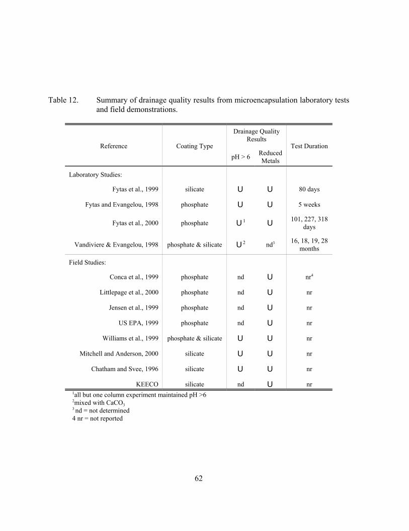
62
Table 12. Summary of drainage quality results from microencapsulation laboratory testsand field demonstrations.
Reference Coating Type
Drainage QualityResults
Test DurationpH > 6 Reduced
Metals
Laboratory Studies:
Fytas et al., 1999 silicate U U 80 days
Fytas and Evangelou, 1998 phosphate U U 5 weeks
Fytas et al., 2000 phosphate U1 U101, 227, 318
days
Vandiviere & Evangelou, 1998 phosphate & silicate U2 nd3 16, 18, 19, 28months
Field Studies:
Conca et al., 1999 phosphate nd U nr4
Littlepage et al., 2000 phosphate nd U nr
Jensen et al., 1999 phosphate nd U nr
US EPA, 1999 phosphate nd U nr
Williams et al., 1999 phosphate & silicate U U nr
Mitchell and Anderson, 2000 silicate U U nr
Chatham and Svee, 1996 silicate U U nr
KEECO silicate nd U nr1all but one column experiment maintained pH >62mixed with CaCO33 nd = not determined4 nr = not reported
63
5.2.4. Potential Use of Microencapsulation Technology to Address Mine WasteIssues in Minnesota
Application of microencapsulation techniques are likely to be very site-specific based onindividual rock types. It has been suggested that physical parameters such as particle size andshape may determine the extent to which an effective microencapsulation coating can be induced(Evangelou, 2000). Furthermore, mineralogic characteristics of the waste material may alsoaffect microencapsulation effectiveness. A coating solution that inhibited pyrite oxidation in afield demonstration may not effectively encapsulate pyrrhotite-bearing waste material (i.e. fromthe Duluth Complex). Therefore, laboratory tests should be conducted on specific rock typesto optimize the method of microencapsulation prior to implementation of a field-scale project.
Field demonstrations of microencapsulation technology suggest that a wide range of metals canbe immobilized in soils and tailings using a phosphate- or silicate-type coating (Chatham andSvee, 1996; Conca et al., 1999; Jensen et al., 1999; US EPA, 1999; Williams et al., 1999;Littlepage et al., 2000; Mitchell and Anderson, 2000). While these results look promising, theexact method of application on an operational scale is unclear at this time. Several questionsstill need to be answered:
• How are microencapsulation coatings induced under field conditions?• How are optimized coating solutions determined in the laboratory scaled up for use inthe field?• Most of these studies used pyritic tailings or finely crushed waste rock. Can a uniformcoating on larger particle size material (i.e. 1-2 inches) be achieved?• What is the long-term stability of these coatings?
5.3. Organic Amendments
The following information was excerpted from Gusek et al. (in progress). Oxygen is one of thekey reactants in the generation of acidic drainage from reactive mine wastes (reactions 1 and 2).If the presence of oxygen within a stockpile, tailings basin, or waste rock dump can be limited,the rate of acid generation can be minimized. One approach is to intermix organic material withthe waste. As the organic material decomposes, it consumes oxygen (reaction 12):
CH2O + O2(g) 6 CO2 + H2O (12)
where, CH2O represents a generic organic material. If adequate organic material is present, therate of oxygen consumption will exceed the rate of oxygen diffusion, preventing oxygen fromreacting with reactive minerals. Ultimately, organic materials may begin to ferment, producingreducing conditions within the waste. Under reducing conditions the rate of sulfide oxidationis extremely low. Reducing conditions also favor sulfate reducing bacteria, which help increasedrainage pH and remove metals from pore waters.
64
Although there are several case studies where organic material has been placed on top of tailings(Appendix 3), there is little information on incorporation of organic material into mine waste.Greenworld Science has several patents on the use of this technology and have injected solubleorganics at metal mining sites to remediate contaminated groundwater (Greenworld Science).
5.4. References on the Chemical Stabilization of Reactive Mine Wastes
Adams, R.L.; Ninesteel, J.J.; Rauch, H.W. 1994. Laboratory testing of coatings for preventionof acid drainage in underground coal mines. In: Internat. Land Reclamation and Mine DrainageConf. and 3rd Internat. Conf. on the Abatement of Acidic Drainage, Pittsburgh, PA, April 24-29,2, pg 218-225.
Chatham,W.H.; Svee,W.A. 1996. Evaluation of KEECO product KB-SEA to permanently fixarsenic and other heavy metals in mine tailings characteristic of southwest Montana. (Preparedfor Bureau of Abandoned Mines, Department of Environmental Quality, State of Montana)(Phase 1 Sample characterization and batch stability tests.) University of Montana, Butte, MT.56 p.
Chen, Y.; Belzile, N.; Goldsack, D.E. 1999. Passivation of pyrite oxidation by organiccompounds. In: Mining and the Environment Conf. Proc., Sudbury, Ontario, Sept. 13-17, 3, pg1063-1072.
Conca, J.; Wright, J.; Mockler, T.J. 1999. Phosphate-induced metal stabilization for theremediation of acid mine drainage and heavy-metal contamination. In: Mining and theEnvironment Conf. Proc., Sudbury, Ontario, Sept. 13-17, 3, pg 1143-1152.
Condon, P. 1999. Improved waste rock pile design at the Kennecott Greens Creek Mine. In:Proc. 6th Internat. Conf. on Tailings and Mine Waste ‘99, Fort Collins, CO, USA, Jan. 24-27,A.A. Balkema, Rotterdam, Netherlands, 808 p.
Davis, A.; Eary, L.E.; Helgen S. 1999. Assessing the efficacy of lime amendment togeochemically stabilize mine tailings. Environ. Sci. and Tech., 33, pg 2626-2632.
Day, S. J. 1994. Evaluation of acid generating rock and acid consuming rock mixing to preventacid rock drainage. In: Internat. Land Reclamation and Mine Drainage Conf. and 3rd Internat.Conf. on the Abatement of Acidic Drainage, Pittsburgh, PA, April 24-29, 2, pg 77-86.
Evangelou, V. P. 1994. Potential microencapsulation of pyrite by artificial inducement of FePO4coatings. In: Internat. Land Reclamation and Mine Drainage Conf. and 3rd Internat. Conf. onthe Abatement of Acidic Drainage, Pittsburgh, PA, April 24-29, 2, pg 96-103.
Evangelou, V. P. 1996. Oxidation proof silicate surface coating on iron sulfides. U.S. Patent,Patent number 5494703.
65
Evangelou, V. P. 2000. Department of Agronomy, Iowa State University, Ames, IA. personalcommunication.
Evans, D.R.; Rose, A.W. 1995. Experiments on alkaline addition to coal mine spoil. In:Mining and the Environment Conf. Proc., Sudbury, ON, May 28-June 1, 1, pg 49-58.
Fytas, K.; Bousquet, P.; Evangelou, B. 1999. Application of silicate coatings on pyrite to preventacid mine drainage. In: Mining and the Environment Conf. Proc., Sudbury, Ontario, Sept. 13-17, 3, pg 1199-1207.
Fytas, K.; Bousquet, P.; Evangelou, B. 2000. Silicate coating technology to prevent acid minedrainage. In: Proc. of the 5th Internat. Conf. on Acid Rock Drainage (ICARD), Denver, CO,May 21-24, 1, pg 87-95.
Fytas, K.; Evangelou, B. 1998. Phosphate coating on pyrite to prevent acid mine drainage.Internat. J. Surface Mining, Reclamation and Environment, 12, pg 101-104.
Georgopoulou, Z.J.; Fytas, K.; Soto, H.; Evangelou, B. 1995. Pyrrhotite coating to preventoxidation. In: Mining and the Environment Conf. Proc., Sudbury, ON, May 28-June 1, 1, pg7-16.
Green World Science, Boise, ID. www.greenworldscience.com.
Gusek, J.J. et al. 2001. Draft: Handbook of Technologies for Avoidance and Mitigation of MetalMine Drainage, Acid Drainage Technology Initiative (ADTI), Publ. by University of Reno, NV,in progress.
Jensen, R.; Sogue, A.; Schurman, S. 1999. Treating heavy metals in mine soil and waste usingEnvirobondTM binder. In: Proc. 6th Internat. Conf. on Tailings and Mine Waste ‘99, Fort Collins,CO, USA, Jan. 24-27, A.A. Balkema, Rotterdam, Netherlands, 808 p.
KEECO (Klean Earth Environmental Company), Lynnwood, WA.
Kempton, J.H.; Swanson, D.; Bennett, M.; MacDonald, R.; Locke, W.; Gillespie, C.; Lechner,M.; Maley, P. 1997. Application of probabilistic acid/base accounting to minimize waste-rockhandling in semi-arid climates. In: Proc. 4th Internat. Conf. on Acid Rock Drainage (ICARD),Vancouver, British Columbia, May 31-June 6, 2, pg 871-888.
Lapakko, K.A.; Antonson, D.A.; Wagner, J.R. 1997. Mixing of alkaline solids with finely-crushed acid-producing rock. In: Proc. 4th Internat. Conf. on Acid Rock Drainage (ICARD),Vancouver, British Columbia, May 31-June 6, 3, pg 1345-1360.
66
Lapakko, K.A.; Antonson, D.A.; Wagner, J.R. 2000. Mixing of rotary kiln fines with fine-grained acid-producing rock. In: Proc. of the 5th Internat. Conf. on Acid Rock Drainage(ICARD), Denver, CO, May 21-24, pg 901-910.
Littlepage, B.; Schurman, S.; Maloney, D. 2000. Treating metals contaminated sludges withEnvirobondTM. Mining Environmental Management, May, pg 22.
Maki, S.; Belzile, N.; Goldsack, D. 1995. Inhibition of pyrite oxidation by surface treatment. In: Mining and the Environment Conf. Proc., Sudbury, ON, May 28-June 1, 1, pg 1-5.
Mehling, P.E.; Day, S.J.; Sexsmith, K.S. 1997. Blending and layering waste rock to delay,mitigate or prevent acid generation: A case study review. In: Proc. 4th Internat. Conf. on AcidRock Drainage (ICARD), Vancouver, British Columbia, May 31-June 6, 2, pg 951-969.
Mitchell, P.; Anderson, A. 2000. Silica micro encapsulation treatment of tailings. MiningEnvironmental Management, May, pg 16-17.
Morin, K.A.; Hutt, N.M. 2000. Discrete-zone blending of Net-acid-neutralizing and net-acid-generating rock: Avoiding the argument over appropriate ratios. In: Proc. of the 5th Internat.Conf. on Acid Rock Drainage (ICARD), Denver, CO, May 21-24, pg 797-806.
Moskalyk, R.R. 1995. Development of a protective cover for mine waste rock. In: Mining andthe Environment Conf. Proc., Sudbury, ON, May 28-June 1, 1, pg 99-108.
Roy, S.; Worral, F. 1999. Pyrite oxidation in coal-bearing strata - the use of P-blockingtechniques. In: Mining and the Environment Conf. Proc., Sudbury, Ontario, Sept. 13-17, 1, pg177-181.
Rybock, J.; Mitchell, P.; Wheaton, A.; Hopper, R. 1999. Silica micro encapsulation: aninnovative technology for the prevention and treatment of ARD. Proc. Randol Gold & SilverForum, ‘99. Denver, CO, May 12-14.
Stewart, B.R.; Jackson, M.L.; Daniels, W.L. 1994. The effects of fly ash blending rates and ashproperties on leachate quality from fly ash/coal refuse mixtures. In: Internat. Land Reclamationand Mine Drainage Conf. and 3rd Internat. Conf. on the Abatement of Acidic Drainage,Pittsburgh, PA, April 24-29, 2, pg 425.
US EPA (1999): EnvironbondTM Process: Rocky Mountain Remediation Services. SuperfundInnovative Technology Evaluation, Demonstration Bulletin, July, EPA/540/MR-99/502.
Vandiviere, M.M.; Evangelou, V.P. 1998. Comparative testing between conventional andmicroencapsulation approaches in controlling pyrite oxidation. J. Geochem. Exploration, 64,pg. 161-176.
67
Williams, B.C.; Nimmer, R.E.; McGeehan, S.L. 1999. Demonstration of metals-fixationtechnologies on the Coeur d’Alene River, Idaho. In: Proc. 6th Internat. Conf. on Tailings andMine Waste ‘99, Fort Collins, CO, USA, Jan. 24-27, A.A. Balkema, Rotterdam, Netherlands,808 p.
Zhang, Y.L.; Evangelou, V.P., 1998. Formation of ferric hydroxide-silica coatings on pyrite andits oxidation behavior. Soil Sci., 163, 1, pg 53-62.
68
6. Biological Stabilization of Reactive Mine Wastes
6.1. Inhibition of Biological Sulfide Oxidation Using Bactericides
Bacteria, such as Thiobacillus ferrooxidans, have been shown to catalyze the oxidation offerrous iron in reactive mine waste effluents below a pH of approximately 4.5. Bacterialoxidation produces acid, which may result in highly acidic drainage. Surfactants have beenshown to interrupt bacterial activity, reducing the rate of oxidation, and therefore, controllingthe rate of drainage acidification.
Surfactants can be obtained as a powder or in a controlled release pellet. Powdered surfactantscan be slurried with water and sprayed directly onto the mine waste material, or incorporatedwith the mine waste material as it is deposited. Drawbacks to powdered surfactants are that theyare easily flushed through the waste material and that they degrade over time. Consequently,surfactants require frequent re-application. Re-application rates are estimated at three to sixmonths (Patterson, 1987; Delaney et al., 1997).
Control release pellets incorporate the surfactant in a rubberized matrix. The surfactant isgradually released through a diffusion mechanism. Since pellets are not likely to be flushedfrom the waste material, their bactericidal properties can last for several years.
Recently, a second class of bactericides has been investigated. Thiol-blocking agents havebeen shown to block the oxidation thiosulfate and sulfur to sulfate (i.e. sulfuric acid). Most ofthese chemicals are toxic and unsuitable for environmental applications. However, one class ofthiol-blocking agents, heterocyclic mercaptans, are considered “relatively non-toxic.”Heterocyclic mercaptans, have been reported to inhibit the activity of Thiobacillus thioparus,a neutrophilic sulfur-oxidizing bacteria, in laboratory column and field tests (Stichbury et al.,1995; Lortie et al., 1999). As with the surfactants, the affects of heterocyclic mercaptans aretemporary and would require re-application.
6.2. Assessment of Bactericides as Sulfide Oxidation Inhibitors
6.2.1. Preliminary Evaluation of Bactericides
Prior to application on an operational-scale, physical, chemical, and biological characterizationof the waste material should be completed. Laboratory studies are generally designed todetermine the acid generation potential in terms of sulfide minerals present as well as bacterialactivity (i.e. bacteria counts). This information, used in conjunction with laboratory columntests, can be used to determine an appropriate bactericide application rate for a specific wasterock type (Kleinmann and Erickson, 1988). However, application rates determined in thelaboratory do not always extrapolate well to operational-scale, environmental conditions(Patterson, 1987; Delaney et al., 1997).
69
6.2.2. Parameters Used to Assess Bactericide Effectiveness
The effectiveness of a bactericide application can be measured in terms of the quality of waterdraining from the mine waste. This can be determined in terms of drainage pH, acidity,chemical release (e.g. sulfate, iron, and other metals), and bacteria counts. If the application ofbactericide successfully inhibits biological oxidation of sulfides in a mine waste, drainage pHshould remain neutral, while acidity, chemical release of sulfate and metals, and bacteria countsremain low.
In laboratory and field studies reported in the literature, the effectiveness of surfactants asbactericides was frequently reported in terms of drainage acidity (Tables 6.2.2a and 6.2.2b).Unfortunately, these data did not indicate whether or not the drainage met the environmentalwater quality standard (pH >6). The fact that acidity was present suggested that these drainagesdid not meet this standard. This is not an unexpected result because surfactants inhibit theactivity of acidophilic bacteria. Acidophilic bacteria do not become active until the pH reachesan acidic range, approximately 4-4.5. Consequently, drainage pH values as low as 4 can beexpected when surfactants are used as bactericides.
Heterocyclic mercaptans, however, inhibit the activity of neutrophilic sulfide oxidizingbacteria. When heterocyclic mercaptans are used as bactericides, drainage pH values in theneutral range are more likely to occur. Drainage pH did remain elevated in the two studies thathave been conducted on heterocyclic mercaptans (Stichbury et al., 1995; Lortie et al., 1999).However, it did not necessarily remain above 6.0 (Tables 13 and 14).
6.3. Cost Analysis of Bactericides
Based on case studies presented by Benedetti et al. (1990) and Rastogi et al. (1990), a singleapplication of surfactant to an acre of waste material will cost between $1000 and $3000. Notethat these are 1990 dollars and have not been adjusted. These cost estimates do not include thoseassociated with waste disposal, neutralization chemicals, grading, or other reclamation measures.No estimates were found for heterocyclic mercaptans.
6.4. Potential Use of Bactericides to Inhibit Sulfide Oxidation in Minnesota MineWastes
Bactericide proponents claim that bactericides show promise as a preventative strategy againstthe development of acidic drainage from mine wastes. They are attractive because they areinexpensive and can be applied easily either sprayed on as a slurry or distributed within thewaste in pellet form. Bactericides appear to be the most effective at preventing acid minedrainage when they are used on fresh waste material and reapplied frequently throughoutoperations. They should not be expected to remediate an existing drainage problem.
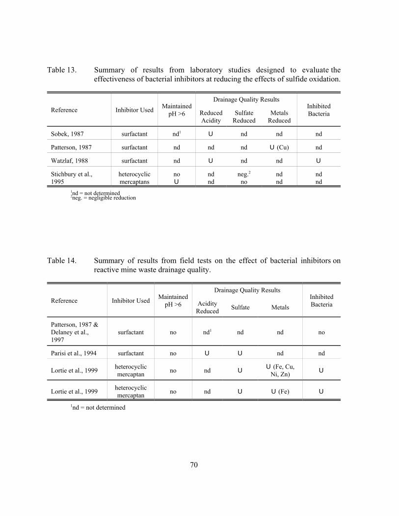
70
Table 13. Summary of results from laboratory studies designed to evaluate theeffectiveness of bacterial inhibitors at reducing the effects of sulfide oxidation.
Reference Inhibitor Used MaintainedpH >6
Drainage Quality ResultsInhibitedBacteriaReduced
AciditySulfate
ReducedMetals
Reduced
Sobek, 1987 surfactant nd1 U nd nd nd
Patterson, 1987 surfactant nd nd nd U (Cu) nd
Watzlaf, 1988 surfactant nd U nd nd U
Stichbury et al.,1995
heterocyclicmercaptans
noU
ndnd
neg.2
nondnd
ndnd
1nd = not determined2neg. = negligible reduction
Table 14. Summary of results from field tests on the effect of bacterial inhibitors onreactive mine waste drainage quality.
Reference Inhibitor Used MaintainedpH >6
Drainage Quality ResultsInhibitedBacteriaAcidity
Reduced Sulfate Metals
Patterson, 1987 &Delaney et al.,1997
surfactant no nd1 nd nd no
Parisi et al., 1994 surfactant no U U nd nd
Lortie et al., 1999 heterocyclicmercaptan no nd U
U (Fe, Cu,Ni, Zn) U
Lortie et al., 1999 heterocyclicmercaptan no nd U U (Fe) U
1nd = not determined
71
It is important to remember that bactericides represent a short-term mitigative strategy that willrequire the use of another, longer-term mitigative strategy for long-term control. The mostfrequently reported objective of bactericide usage has been to prevent acidification long enoughfor vegetation to become established on a reclaimed surface. In these cases, reclamation effortsare usually expected to minimize the amount of water that must be collected and treated priorto discharge into the environment. Bactericides used in this manner are considered to be a costeffective method to minimize treatment costs. Alternatively, establishment of a healthyvegetative cover may, in some situations, be sufficient to prevent future acidification ofdrainage. Although reported less frequently, it seems logical that bactericides could be used toprevent acidification of mine wastes during operations until a dry cover system, including avegetated surface, can be placed over the mine waste.
There are two major drawbacks to the use of bactericides. First, surfactants cannot be reliedupon to maintain drainage pH above 6.0. This pH may be sufficient to maintain a healthyvegetative cover in some instances. However, it generally does not meet acceptableenvironmental standards. As a result, the use of surfactants alone is not a viable option forpreventing acidic drainage problems in Minnesota.
Second, the “relatively non-toxic” nature of heterocyclic mercaptans has not been defined in theliterature. It is unclear at this time whether or not heterocyclic mercaptans can or should bereleased to the environment. Furthermore, neither of the two heterocyclic mercaptans describedin the literature could be found in the Minnesota Pollution Control Agency (MN PCA) database(Clark, 2000). Based on information found on Material Safety Data Sheets for these twochemicals, aquatic toxicity has not yet been determined. Since the MN PCA does not haveadequate toxicity information on either of the two heterocyclic mercaptans, no standard existsto govern their usage. Consequently, the MN PCA recommends conducting biological toxicitytests on drainages containing these compounds prior to extensive use (Clark, 2000).
6.5. References on the Use of Bactericides
Benedetti, B.A.; Rastogi, V.; Sobek, A.A. 1990. Minimizing water treatment costs at activeoperations. Nat. Symp. on Mining, Knoxville, TN.
Clark, R. 2000. Operations/Planning/Major Facilities, North District, Minnesota PollutionControl Agency. personal communication.
Delaney, T.; Hockley, D.; Sollner, D. 1997. Applications of methods for delaying the onset ofacidic drainage. In: Proc. 4th Internat. Conf. on Acid Rock Drainage (ICARD), Vancouver,British Columbia, May 31-June 6, 2, pg 795-810.
Fox, L.A.; Rastogi, V. 1983. Developments in controlled release technology and its applicationin acid mine drainage. Symposium on Mining, Hydrology, Sedimentology, and Reclamation.University of Kentucy, Lexington, KY.
72
Gould, W.D.; Lortie, L.; Bechard, G. 1996. Method for inhibiting the formation of acid minedrainage. U.S. Patent #5,550,141.
Kleinmann, R.L.P. 1980. Bactericidal control of acid problems in surface mines and coalrefuse. Symp. Surf. Mining Hydrology, Sedimentology, and Reclamation, University ofKentucky, Dec 1-5, pg 333-337.
Kleinmann, R.L.P.; Erickson, P.M. 1988. Control of acid drainage from coal refuse usinganionic surfactants. US BOM Report of Investigations 8847. 16p.
Lortie, L.; Gould, W.D.; Stichbury, M.; Blowes, D.W.; Thurel, A. 1999. Inhibitors for theprevention of acid mine drainage. In: Mining and the Environment Conf. Proc., Sudbury,Ontario, Sept. 13-17, 3, pg 1191-1198.
Parisi, D.; Horneman, J; Rastogi, V. 1994. Use of bactericides to control acid mine drainagefrom surface operations. In: Internat. Land Reclamation and Mine Drainage Conf. and 3rd
Internat. Conf. on the Abatement of Acidic Drainage, Pittsburgh, PA, April 24-29, 2, 319-325.
Patterson, R.J. 1987. Environmental and reclamation measures at Equity Silver Mines Ltd. Proc.Acid Mine Drainage Seminar/Workshop, March 23-26, Halifax, Nova Scotia, pg 457.
Rastogi, V.; Sobek, A.A. 1986. The economics of using bactericides in active mining andreclamation to control acid mine drainage. National Symposium on Mining, Hydrology,Sedimentology, and Reclamation. University of Kentucky, Lexington, KY.
Rastogi, V.; Sobek, A.A.; Benedetti, D.A. 1990. Prevention of water pollution problems inmining: The bactericide technology. Society for Mining, Metallurgy, and Exploration, Inc.
Sobek, A.A. 1987. The use of surfactants to prevent AMD in coal refuse and base metal tailings.Proc. Acid Mine Drainage Seminar/Workshop, Halifax, Nova Scotia. March 23-26, 1987. pg357.
Sobek, A.A.; Benedetti, D.A.; Rastogi, V. 1990. Successful reclamation using controlled releasebactericides: Two case studies. American Society for Surface Mining and ReclamationConference, Charleston, WV.
Stichbury, M.; Bechard, G.; Lortie, L.; Gould, W.D. 1995. Use of inhibitors to prevent acidMine drainage. In: Mining and the Environment Conf. Proc., Sudbury, ON, May 28-June 1,2, pg 613-622.
Unknown. 1995. ProMac: bacterial inhibition. Mining Environmental Management, June, pg27-29.
73
Watzlaf, G.R. 1988. Chemical inhibition of iron-oxidizing bacteria in waste rock and sulfidetailings and effect on water quality. Mine Drainage and Surface Mine Reclamation Conference,Pittsburgh, PA.
Ziemkiewicz, P.F. 1995. Acid mine drainage control technologies. Ch 5. Acid Mine DrainageControl and Treatment. West Virginia University and the National Mine Land ReclamationCenter, Morgantown, WV.
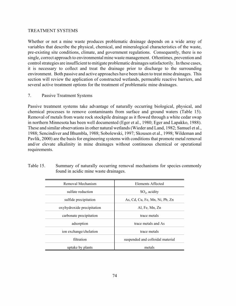
74
TREATMENT SYSTEMS
Whether or not a mine waste produces problematic drainage depends on a wide array ofvariables that describe the physical, chemical, and mineralogical characteristics of the waste,pre-existing site conditions, climate, and government regulations. Consequently, there is nosingle, correct approach to environmental mine waste management. Oftentimes, prevention andcontrol strategies are insufficient to mitigate problematic drainages satisfactorily. In these cases,it is necessary to collect and treat the drainage prior to discharge to the surroundingenvironment. Both passive and active approaches have been taken to treat mine drainages. Thissection will review the application of constructed wetlands, permeable reactive barriers, andseveral active treatment options for the treatment of problematic mine drainages.
7. Passive Treatment Systems
Passive treatment systems take advantage of naturally occurring biological, physical, andchemical processes to remove contaminants from surface and ground waters (Table 15).Removal of metals from waste rock stockpile drainage as it flowed through a white cedar swapin northern Minnesota has been well documented (Eger et al., 1980; Eger and Lapakko, 1988).These and similar observations in other natural wetlands (Wieder and Land, 1982; Samuel et al.,1988; Sencindiver and Bhumbla, 1988; Sobolewski, 1997; Skousen et al., 1998; Wildeman andPavlik, 2000) are the basis for engineering systems with conditions that promote metal removaland/or elevate alkalinity in mine drainages without continuous chemical or operationalrequirements.
Table 15. Summary of naturally occurring removal mechanisms for species commonlyfound in acidic mine waste drainages.
Removal Mechanism Elements Affected
sulfate reduction SO4, acidity
sulfide precipitation As, Cd, Cu, Fe, Mn, Ni, Pb, Zn
oxyhydroxide precipitation Al, Fe, Mn, Zn
carbonate precipitation trace metals
adsorption trace metals and As
ion exchange/chelation trace metals
filtration suspended and colloidal material
uptake by plants metals
75
7.1. Constructed Wetlands
Although the design of wetland treatment systems can vary substantially, there are two basictypes; aerobic (overland or surface flow) wetlands, and organic substrate (vertical flow)wetlands (Eger, 2000). Settling ponds and alkaline producing systems (i.e. SAPS and openlimestone channels) are often incorporated into passive treatment system designs to improveeffluent metal and alkalinity levels. Constructed wetlands require little operational attention ormaintenance, and therefore, may be favorable over conventional active treatment systems.Disadvantages of constructed wetland systems include the large area of open land required foradequate treatment, the relatively low flow requirements, and diminished performance in coldclimates.
7.1.1. Aerobic Wetlands
Aerobic wetland systems promote metal removal via oxidation reactions in the surface water orupper portion of the substrate where oxygen is present in the highest concentrations. Ironremoval occurs primarily through precipitation of ferric oxyhydroxides. Trace metals areremoved by adsorption, chelation, or ion exchange processes associated with the organiccomponent of the substrate. Since these reactions are favored at high pH, aerobic wetlands aremost effective when the mine drainage is net alkaline.
Aerobic wetlands can be used for acidic drainages following adequate pretreatment using ananoxic limestone drain (ALD). ALDs are typically constructed in an area with seeps, where thewater will contain little to no dissolved oxygen. The presence of even a small amount ofdissolved oxygen will result in precipitation of iron oxyhydroxides, which can coat limestonerendering it ineffective and/or plug the drain. Thus, oxygen must be excluded from the drain.
An ALD usually consists of a trench constructed to intercept the contaminated ground water andfilled with two to three inch limestone. The goal of the drain is to provide sufficient alkalinityto the drainage so that when the water surfaces, there is sufficient alkalinity to maintain a neutralpH. Outflow from the drain collects in an aerobic wetland or settling pond to remove iron andother metals.
7.1.2. Organic Substrate Wetlands
Organic substrate wetlands are anaerobic systems that promote bacterial sulfate reduction, whichproduces dissolved hydrogen sulfide and bicarbonate alkalinity (reaction 13),
2CH2O + SO42! 6 H2S + 2HCO3
! (13)
where CH2O represents a low molecular weight organic substance such as lactate or acetate.
The wetland is constructed with organic material (e.g. compost) that is usually supplementedwith limestone. Trace metal removal occurs primarily through the precipitation of metal
76
Passive Treatment SystemDesign Criteria
OpenLimestoneChannel
Heavy Metals Present
No
Determine Flow RateAnalyze Water
ChemistryCalculate Loadings
Net AlkalineWater
Net AcidicWater
SettlingPond
AerobicWetland
Discharge
AnoxicLimestone
Drain
AnaerobicWetland
DO, FeIII, and,Al <1 mg/L?
SAPS
SettlingPond
SettlingPond
SettlingPond
Aeration andSettling Pond
OR
Net AcidicWater
No
Yes
Meets EffluentStandards?
Yes
No
Net AlkalineWater
Heavy Metals Present
Polish for DO, Mn, BOD
Meets EffluentStandards?
Yes
Re-evaluateDesign
Figure 4. Constructed wetland design depends upon the chemistry of water tobe treated. Modified Gusek et al., 2001.
sulfides, hydroxides, and carbonates. Acid is neutralized both through sulfate reductionprocesses and limestone dissolution. Organic substrate wetlands are most effective when themine drainage is acidic.
7.1.3. Assessment of Constructed Wetland Treatment System Designs and Size
Wetland treatment systems are evaluated primarily by the water quality at the outflow of thewetland (Hedin et al., 1994). In order to produce an effluent which meets water qualitystandards, wetlands must be designed properly. For detailed information on wetland treatmentdesign considerations, a reasonably comprehensive overview was compiled by Wildeman et al.(1993).
Important factors in the design are the drainage pH and total metal load (Figure 4). Net alkalinewaters can be treated using an aerobic wetland. Net acidic waters must either be pretreatedusing an ALD or treated using an organic substrate wetland. If the raw water contains highlevels of dissolved oxygen and iron, an organic substrate wetland is the preferred treatmentstrategy. Oftentimes, a combined system is the most effective. Several wetland cells may beconnected to optimize metal removal or to treat large flow volumes.
77
Wetland treatment systems require large areas of space in order to be effective. Inadequatemetal removal and poor performance will result if the size of the system is underestimated.Hedin et al. (1994) developed sizing criteria for constructed wetlands based on previous cases.In order to consistently meet regulatory guidelines for an alkaline drainage, sizing factors were10 g/m2d and 0.5 g/m2d for iron and manganese, respectively. The acidity sizing factor for anet acid drainage was 3.5 g/m2d. It is important to note that these “compliance criteria” weregenerated for coal mine drainages in Appalachia and may not be appropriate for metal miningoperations or other regions. However, Wildeman et al. (1993) considered these sizing factorsreasonable for wetland treatment of metal mine drainages in Colorado.
7.1.4. Cost Analysis of Constructed Wetland Treatment Systems
Costs for these systems can vary depending on the system design and complexity. Constructioncosts for liners, trenches, and spillways will increase as the number of treatment cells increase.Since constructed wetland treatment system designs are site-specific, average construction costsare difficult to determine. Costs estimates include a wide variety of capital, construction, andoperation costs (Table 16). It has been estimated that constructed wetland installation costsrange from $5 to $32/m2 (Wildeman et al., 1993). Installation of constructed wetlands at theDunka Mine site in northern Minnesota varied from $19 - $31/m2 (Eger, 2000).
Table 16. Summary of major cost components for constructed wetlands (modified fromWildeman et al., 1993).
Capital Construction Operation/Maintenance
engineering(design, testing, & specifications) personnel inspections
environmental studies & permitting transportation monitoring
land acquisition site preparation cleaning of conveyances
access (rights of way) source control /diversion flow adjustments
earthwork major overhauls (i.e. substraterejuvenation/replacement)
basin lining
concrete
plumbing
substrate conditioning /installation
vegetation
7.1.5. Constructed Wetland Treatment of Problematic Drainages in Minnesota
78
The majority of constructed wetlands have been applied to coal mine drainage issues. However,they do have some potential for addressing hard rock mining issues. A survey of 128 coal minedrainages found that coal mine drainages can have copper, nickel, and zinc concentrations ashigh as 2.49, 10, and 146 mg/L, respectively (Hyman and Watzlaf, 1996). These levels arecomparable to those expected for hard rock mine drainage.
The MN DNR has conducted considerable research on the topic of constructed wetlands to treatproblematic drainages on a laboratory-, field-, and operational-scale. Field studies have alsoaddressed issues related to establishing wetlands on sulfidic tailings as a preventative technique.A bibliography of MN DNR publications related to these studies is provided here (Appendix 6).
Currently in Minnesota, there are five operating constructed wetland treatment systems at theDunka Mine site near Babbitt, and one proposed sulfate reduction system at the Soudan StatePark (Eger, 2000). The sulfate reduction system proposed to treat mine drainage at the SoudanState park will probably be built in the spring of 2001.
The five operating systems were designed to treat drainage from covered stockpiles (section4.2.5). The drainage is generally near-neutral, although pretreatment systems help increasedrainage pH from W1-D and Seep 1 prior to wetland treatment. These drainages also containelevated levels of nickel, copper, cobalt, and zinc (Eger and Lapakko, 1991; Eger and Melchert,1992). These systems are basically overland flow wetlands with some subsurface flow occursthrough limestone drains which were built as part of the berms within the wetlands. Treatmentefficiency varies for each of the five wetland systems due to the fact that each system treatsdrainage from a different stockpile area (Table 17). In general, these wetlands have decreasedmetal loads in the stockpile drainage (Eger et al., 1996, 1997, 2000b; MN DNR, unpublisheddata).
Based on results from the Dunka Mine site, constructed wetland treatment of near-neutraldrainage appears to be a viable treatment system throughout much of the year. However, it isimportant to note that the wetlands at Dunka are part of an integrated mine waste managementsystem involving dry covers on the stockpiles (section 4.2.5) and a neutralization treatment plant(section 8.8.2). Wetland treatment alone has not been able to consistently meet regulatorydischarge limits at Dunka.
Two climatic conditions common to northern Minnesota limit the extent to which constructedwetlands can be used to treat problematic mine drainages. First, cold temperatures typicalduring winter months severely limit biological activity. Second, constructed wetland treatmentfailures are common when flow rates fluctuate widely or are too high. Consequently, elevatedflow rates in the spring (i.e. snow melt) occurring immediately after an extended period of coldwinter temperatures may render constructed wetlands ineffective for a substantial period of time.Due
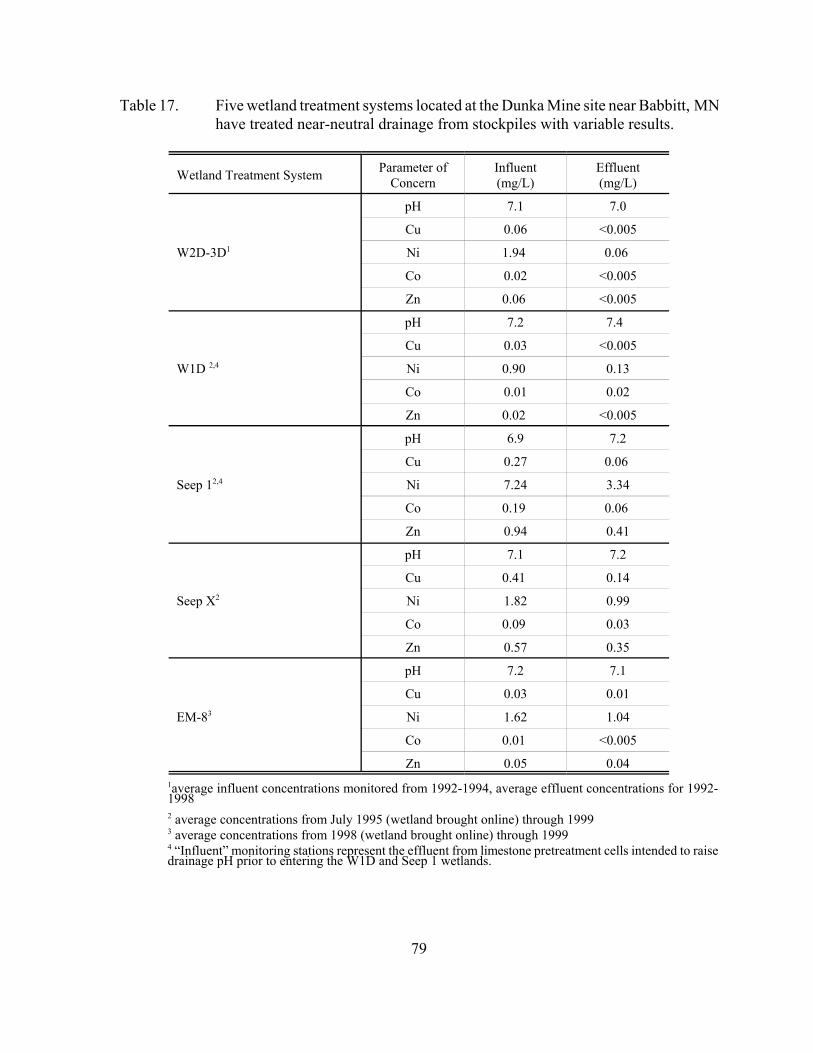
79
Table 17. Five wetland treatment systems located at the Dunka Mine site near Babbitt, MNhave treated near-neutral drainage from stockpiles with variable results.
Wetland Treatment System Parameter ofConcern
Influent(mg/L)
Effluent(mg/L)
W2D-3D1
pH 7.1 7.0
Cu 0.06 <0.005
Ni 1.94 0.06
Co 0.02 <0.005
Zn 0.06 <0.005
W1D 2,4
pH 7.2 7.4
Cu 0.03 <0.005
Ni 0.90 0.13
Co 0.01 0.02
Zn 0.02 <0.005
Seep 12,4
pH 6.9 7.2
Cu 0.27 0.06
Ni 7.24 3.34
Co 0.19 0.06
Zn 0.94 0.41
Seep X2
pH 7.1 7.2
Cu 0.41 0.14
Ni 1.82 0.99
Co 0.09 0.03
Zn 0.57 0.35
EM-83
pH 7.2 7.1
Cu 0.03 0.01
Ni 1.62 1.04
Co 0.01 <0.005
Zn 0.05 0.041average influent concentrations monitored from 1992-1994, average effluent concentrations for 1992-19982 average concentrations from July 1995 (wetland brought online) through 19993 average concentrations from 1998 (wetland brought online) through 19994 “Influent” monitoring stations represent the effluent from limestone pretreatment cells intended to raisedrainage pH prior to entering the W1D and Seep 1 wetlands.
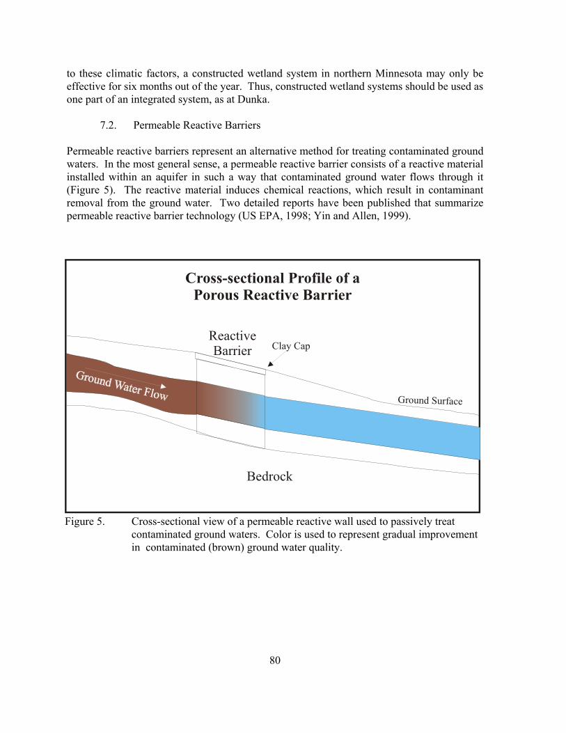
80
Cross-sectional Profile of aPorous Reactive Barrier
Bedrock
ReactiveBarrier Clay Cap
Ground Surface
Figure 5. Cross-sectional view of a permeable reactive wall used to passively treatcontaminated ground waters. Color is used to represent gradual improvementin contaminated (brown) ground water quality.
to these climatic factors, a constructed wetland system in northern Minnesota may only beeffective for six months out of the year. Thus, constructed wetland systems should be used asone part of an integrated system, as at Dunka.
7.2. Permeable Reactive Barriers
Permeable reactive barriers represent an alternative method for treating contaminated groundwaters. In the most general sense, a permeable reactive barrier consists of a reactive materialinstalled within an aquifer in such a way that contaminated ground water flows through it(Figure 5). The reactive material induces chemical reactions, which result in contaminantremoval from the ground water. Two detailed reports have been published that summarizepermeable reactive barrier technology (US EPA, 1998; Yin and Allen, 1999).
81
The mechanisms by which permeable reactive barriers remove contaminants vary dependingupon the type of application. Acidic drainage from mine wastes is usually treated using abiological sulfate reduction system. Sulfate reducing bacteria consume dissolved sulfate,converting it to hydrogen sulfide (reaction 14). Metal removal occurs when the biologicallyproduced sulfide reacts with metals in solution to form insoluble metal sulfides (reaction 15):
SO42! + 2CH2O 6 H2S + 2HCO3
! (14)
H2S + Me2+ 6 MeS + 2H+ (15)
where, CH2O generically refers to an organic carbon source and Me2+ represents a dissolvedmetal.
Adsorption is another mechanism by which metals can be removed from ground waterscontaminated by mining activities. In addition to adsorption to organic substrates in sulfatereducing barriers, laboratory-scale tests have also been conducted on the ability of variousinorganic absorbents to remove metals from contaminated water. Column experiments haveshown that arsenic removal can be achieved using basic oxygen furnace oxide (a by-product ofsteel manufacturing; McRae et al., 1999), zero valent iron (McRae et al., 1999; Su and Puls,2001), activated alumina (McRae et al., 1999), and hydrous ferric oxide (Martin and Kempton,1999). Hydrous ferric oxide (Martin and Kempton, 1999) and zero valent iron (Astrup et al.,2000; Phillips et al., 2000) were also able to remove hexavalent chromium from solution.Recent research in the area of mesoporous molecular sieves (nanostructures with high adsorptivecapacities and specificity) may also have an application in permeable reactive barriers for a widevariety of heavy metals and mercury (Mercier et al., 1999).
Finally, Conca et al. (1999) suggest that phosphate induced metal stabilization can be used ina permeable reactive barrier system to passively remove metals from ground waters. Theremoval mechanism in this system involves the secondary precipitation of metal phosphatephases in the presence of a poorly crystalline apatite mineral referred to as Apatite II. Thissystem is particularly effective at removing U, Pb, Cd, and Zn from solution.
7.2.1. Factors Affecting Permeable Reactive Barrier Performance
Several site-specific factors affect the performance of a permeable reactive barrier. Drainagechemistry, ground water flow patterns and velocity, and site accessibility must be consideredwhen designing a permeable reactive barrier. Careful selection of reactive materials is anothercritical factor in reactive barrier performance. Selected materials must be reactive enough tohandle contaminant loads. However, they must not react so quickly that they are rapidlyconsumed. Materials used in a reactive barrier must also be permeable enough to transmitground water flow at the site for an extended period of time. Finally, materials must be readilyavailable and affordable. Although several different reactive barrier technologies exist,subsequent discussion of these factors will focus on treatment of acid rock drainage using sulfatereduction barriers.
82
Success of a sulfate reducing barrier depends on establishment of sulfate reducing bacteriawithin the barrier. Sulfate reducing bacteria require an organic substrate, nutrients, near neutralpH, and anoxic conditions for optimum growth. The ideal organic substrate should be fresh andcontain short carbon chains with single bonds. Numerous organic materials have been tested.Those that have shown some success include leaf mulch (Waybrant et al., 1995, 1997; Benneret al., 1997, 1999, 2000; McGregor, 1999, 2000), wood wastes (Blowes et al., 1995; Waybrantet al., 1995, 1997; Benner et al., 1997, 1999, 2000), animal by-products (Waybrant et al., 1995;Canty, 1999a,b, 2000), and municipal wastes (Benner et al., 1997, 1999, 2000;Waybrant et al.,1995, 1997;). The use of these particular organic materials is primarily based on laboratoryexperiments conducted by Waybrant et al. (1997). Partially decomposed straw has also beenused as an organic substrate for sulfate reducing bacteria in a reactive barrier with limitedsuccess (Bechard et al., 1991; 1995).
One problem inherent to sulfate reducing reactive barrier systems is that the permeability of thebarrier decreases over time as the organic substrate decomposes. This loss of permeability mayrestrict ground water flow to the point where it is forced around the reactive barrier rather thanthrough it. To avoid this problem, the organic substrate must be thoroughly mixed with amaterial with a relatively high hydraulic conductivity, such as pea gravel. Any layering ofhydraulic conductivities within the reactive barrier may result in channeling, which reducesresidence time and diminishes effectiveness.
The overall hydraulic conductivity of the reactive mixture may be very sensitive to the substrate-gravel ratio. Therefore, permeability tests should be conducted prior to installation to determinethe gravel requirement for a specific substrate and ground water flow. Hydrologic modeling canbe used to determine appropriate target hydraulic conductivities for the reactive mixture. Benneret al. (1997) found that the hydraulic conductivity of the wall must be an order of magnitudegreater than that of the surrounding aquifer to achieve good flow distribution within a reactivebarrier.
Strongly acidic environments typical of acid rock drainage do not favor sulfate reducingbacteria. To avoid this problem, limestone is usually added to the organic substrate to elevatethe solution pH within the barrier. Oxygen will also inhibit the activity of sulfate reducingbacteria. Consequently, a protective cap (e.g. clay) should be placed across the upper sectionof the barrier to minimize oxygen ingress.
83
7.2.2. Evaluation of Reactive Barrier Systems
Field evaluation of reactive barrier systems typically involves the use of monitoring wells andpiezometers. Contaminant removal can be qualitatively estimated by the water chemistry ofsamples collected from monitoring wells placed both up and down gradient from the reactivebarrier. Monitoring wells and piezometers may also be installed within the barrier or at differentdepths. Careful planning and installation makes it possible to track ground water flow andidentify zones of maximum contaminant removal relative to barrier placement. These data areoften used as input for geochemical models.
Geochemical models are used to describe geochemical interactions and mass transport occurringwithin a reactive barrier. Application of reactive transport models is used to meet two importantobjectives. First, models can be used as a design tool. Quantification of potential loss oraccumulation of mass within the barrier and estimation of long-term permeability of thesubstrate are critical factors to consider during the reactive material selection phase of barrierdesign. Second, modeling is used to evaluate reactive barrier performance and to provide insightinto geochemical mechanisms controlling contaminant removal.
7.2.3. Construction Costs Associated with Reactive Barriers
Construction costs for permeable reactive barriers will vary widely depending on the size of thebarrier needed, barrier design, and reactive materials used. Very few operational-scale examplesof permeable reactive barriers used to treat mining impacted ground water were found in theliterature. Probably the most relevant example was the reactive barrier installed at the NickelRim Mine tailings impoundment near Sudbury, Ontario. Materials and installation for thisreactive barrier were estimated to cost US $30,000 (Yin and Allen, 1999). No other costestimates were found in the literature.
7.2.4. Potential Application of Reactive Barrier Technology in Minnesota
Results from laboratory and field studies suggest that permeable reactive barrier technology canbe used to remove sulfate (Waybrant et al., 1995, 1997), metals (Blowes and Ptacek, 1992;Waybrant et al., 1995, 1997; Blowes et al., 1998; Conca et al., 1999; Martin and Kempton, 1999;McRae et al., 1999; Mercier et al., 1999), halogenated organics (Gillham and O’Hannesin, 1992;1994; Yabusake et al., 2001), and phosphate ( Ptacek et al., 1994; Baker et al., 1996, 1997, 1998)from contaminated ground waters. In addition to these, field-scale studies have demonstratedthe use of permeable reactive barriers to treat ground water contaminated with acid rockdrainage (Bechard et al., 1991, 1995; Blowes and Ptacek, 1994; Blowes et al., 1994, 1995;Benner et al., 1997, 1999, 2000; Canty, 1999a, b, 2000; McGregor et al., 1999, 2000) andseepage from landfills (Greenwald et al., 1999). This technology can also be incorporated intoseptic system designs to prevent nitrate contamination of local ground water (Robertson andCherry, 1995).
84
Permeable reactive barriers using sulfate reduction technology may be an attractive strategy totreat certain ground waters contaminated with acid rock drainage. One of the advantages of thisstrategy is that the reactive wall is underground, eliminating the need to create anaerobicconditions for sulfate reducing bacteria. The in-ground location of a permeable reactive barriersystem makes it less visible from the surface, and therefore, more aesthetic than other treatmentsystems. Finally, it is less expensive than typical ground water “pump and treat” strategies,because the reactive barrier is installed within the ground water flow path. These advantagesmake application of permeable reactive barriers particularly attractive at abandoned or inactivemine sites and possibly the toe of tailings impoundments.
However, there are two main disadvantages to this strategy that must be addressed. Permeablereactive barrier systems are not feasible at all sites. In order for a permeable reactive barriersystem to be successful, the contaminated ground water must flow through the barrier. Localhydrogeology must facilitate movement of ground water through the barrier at a rate at whichit can be treated. If subsurface features allows ground water to flow around the barrier, thisstrategy will be ineffective. Consequently, detailed knowledge of the local geohydrologicsetting is required if this strategy is to be considered.
This problem may prove critical for mining applications in northern Minnesota. Bedrock innorthern Minnesota is shallow, with only a few feet of overburden (i.e. glacial till) present inmost areas (Olsen and Mossler, 1982). Correct placement of a permeable reactive barrier in thissituation would be difficult, and in areas with significant outcropping, impossible withoutblasting and excavation.
The second disadvantage is that the long-term effectiveness of permeable sulfate reducingbarriers has not been demonstrated. There are only a few operational-scale demonstrationsreported in the literature. Only three mining-related demonstrations have been cited in thisdocument. Of these three, only one demonstrated the ability to remove metals from groundwater for more than three years (Table 18). This is most likely due to the gradual degradationof the substrate, resulting in a loss of reactivity and/or permeability. Since substrate degradationis inevitable, permeable reactive barriers will have a definite, finite lifetime. For example, thelifetime of the Nickel Rim reactive barrier was calculated to be only fifteen years. This is arather short period of time relative to the potential lifetime of water quality problems associatedwith acid mine drainage (i.e. hundreds of years). Maintenance costs associated with replacingor overhauling reactive barriers may actually be cost prohibitive in some cases. However, acomparison of long-term costs associated with periodic maintenance of a permeable reactivebarrier system to active ground water treatment has not been conducted.
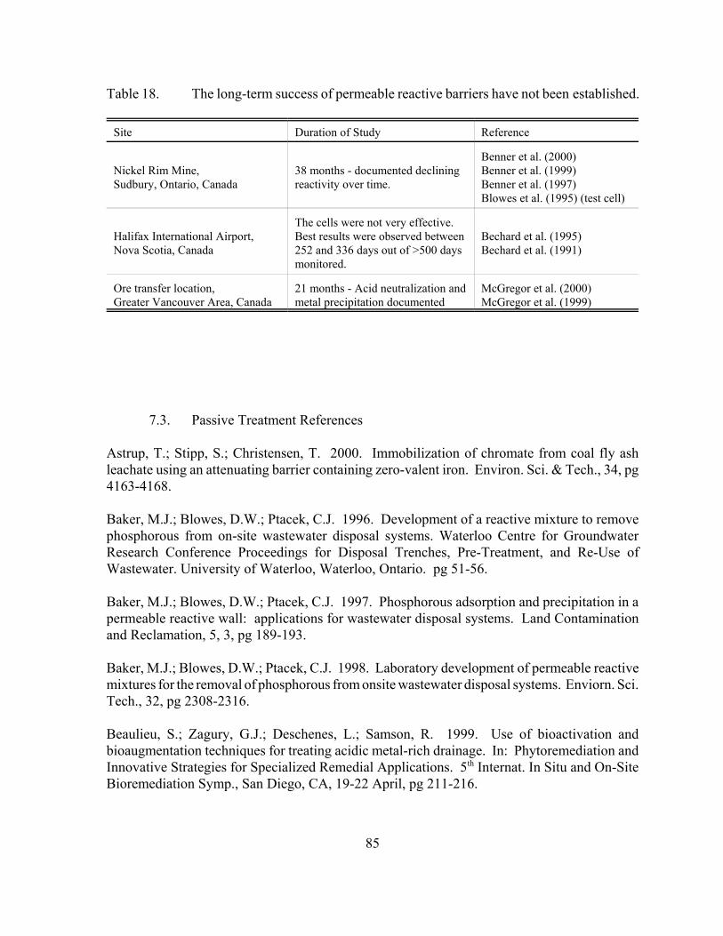
85
Table 18. The long-term success of permeable reactive barriers have not been established.
Site Duration of Study Reference
Nickel Rim Mine,Sudbury, Ontario, Canada
38 months - documented decliningreactivity over time.
Benner et al. (2000)Benner et al. (1999)Benner et al. (1997)Blowes et al. (1995) (test cell)
Halifax International Airport,Nova Scotia, Canada
The cells were not very effective. Best results were observed between252 and 336 days out of >500 daysmonitored.
Bechard et al. (1995)Bechard et al. (1991)
Ore transfer location,Greater Vancouver Area, Canada
21 months - Acid neutralization andmetal precipitation documented
McGregor et al. (2000)McGregor et al. (1999)
7.3. Passive Treatment References
Astrup, T.; Stipp, S.; Christensen, T. 2000. Immobilization of chromate from coal fly ashleachate using an attenuating barrier containing zero-valent iron. Environ. Sci. & Tech., 34, pg4163-4168.
Baker, M.J.; Blowes, D.W.; Ptacek, C.J. 1996. Development of a reactive mixture to removephosphorous from on-site wastewater disposal systems. Waterloo Centre for GroundwaterResearch Conference Proceedings for Disposal Trenches, Pre-Treatment, and Re-Use ofWastewater. University of Waterloo, Waterloo, Ontario. pg 51-56.
Baker, M.J.; Blowes, D.W.; Ptacek, C.J. 1997. Phosphorous adsorption and precipitation in apermeable reactive wall: applications for wastewater disposal systems. Land Contaminationand Reclamation, 5, 3, pg 189-193.
Baker, M.J.; Blowes, D.W.; Ptacek, C.J. 1998. Laboratory development of permeable reactivemixtures for the removal of phosphorous from onsite wastewater disposal systems. Enviorn. Sci.Tech., 32, pg 2308-2316.
Beaulieu, S.; Zagury, G.J.; Deschenes, L.; Samson, R. 1999. Use of bioactivation andbioaugmentation techniques for treating acidic metal-rich drainage. In: Phytoremediation andInnovative Strategies for Specialized Remedial Applications. 5th Internat. In Situ and On-SiteBioremediation Symp., San Diego, CA, 19-22 April, pg 211-216.
86
Bechard, G.; Goudey, P.; Rajan, S.; McCready, R.G.L. 1991. Microbiological process for thetreatment of acidic drainage at the Halifax International Airport. In: Proc. 2nd InternationalConference on the Abatement of Acidic Drainage, (Ed: MEND Program) Quebec MiningAssociation, Ottawa, 3, pg 171-183.
Bechard, G.; McCready, R.G.L.; Koren, D.W.; Rajan, S. 1995. Microbial treatment of acidmine drainage at Halifax International Airport. In: Mining and the Environment Conf. Proc.,Sudbury, ON, May 28-June 1, 2, pg 545-554.
Benner, S.G.; Blowes, D.W.; Gould, W.D.; Herbert, R.B. Jr., Ptacek, C.J. 1999. Geochemistryof a permeable reactive barrier for metals and acid mine drainage. Environ. Sci. Technol. 33,16, pg 2793-2799.
Benner, S.G.; Blowes, D.W.; Ptacek, C.J. 1997. A full-scale porous reactive wall for theprevention of acid mine drainage. Groundwater Monitoring and Remediation, 17, 4, pg 99-107.
Benner, S.; Blowes, D.; Ptacek, C. 2000. Long term performance of the Nickel Rim reactivebarrier: a summary. In: Proc. of the 5th Internat. Conf. on Acid Rock Drainage (ICARD),Denver, CO, May 21-24, 2, pg 1221-1225.
Blowes, D.W.; Ptacek, C.J. 1992. Geochemical remediation of groundwater by permeablereactive walls: removal of chromate by reaction with iron-bearing solids. SubsurfaceRestoration Conf., Dallas, TX, 21-24 June, pg 214-216.
Blowes, D.W.; Ptacek, C.J. 1994. Acid-neutralization mechanisms in inactive mine tailings.Chap. 10. In: Short Course Handbook on Environmental Geochemistry of Sulfide Mine-Wastes.Vol. 22. (Waterloo, Ontario, May 1994) (Eds: Jambor,JL; Blowes,DW) (Short CourseHandbook.) Mineralogical Society of Canada, Ontario, Canada, pg 271-292.
Blowes, D.W.; Ptacek, C.J.; Bain, J.G.; Waybrant, K.R.; Robertson, W.D. 1995. Treatment ofmine drainage water using in situ permeable reactive walls. In: Mining and the EnvironmentConf. Proc., Sudbury, ON, May 28-June 1, 3, pg 979-987.
Blowes, D.W.; Ptacek, C.J.; Benner, S.G.; McRae, C.W.T.; Puls, R.W. 1998. Treatment ofdissolved metals using permeable reactive barriers. Groundwater Quality: Remediation andProtection. Proc. of the GQ ‘98 Conf., Sept. 1998, Tubingen Germany.
Blowes, D.W.; Ptacek, C.J.; Jambor, J.L. 1994. Remediation and prevention of low-qualitydrainage from tailings impoundments. Chap. 13. In: Short Course Handbook on EnvironmentalGeochemistry of Sulfide Mine-Wastes. Vol. 22. (Waterloo, Ontario, May 1994) (Eds:Jambor,JL; Blowes,DW) (Short Course Handbook.) Mineralogical Society of Canada, Ontario,Canada, pg 365-379.
87
Brant, D.L.; Ziemkiewicz, P.F.; Svonavec, J. 1995. Anoxic limestone foundation drains forAMD control in coal refuse piles. In: Mining and the Environment Conf. Proc., Sudbury, ON,May 28-June 1, 2, pg 537-543.
Brodie, G.A. 1991. Engineered wetlands for effective treatment of acid drainage - applications,results, and prospects in the Tennessee Valley. 34th Annual Meeting of the Assoc. of EngineeringGeologists, Chicago, IL, pg 558-568.
Brodie, G.A.; Britt, C.R.; Taylor, H.N. 1992. Staged, aerobic constructed wetlands to treat aciddrainage - the Tennessee Valley Authority Program. West Virginia Surf. Mine Drainage TaskForce Symp., Morgantown, WV.
Brodie, G.A.; Britt, C.R.; Tomaszewski, T.M.; Taylor, H.N. 1991. Anoxic limestone drains toenhance performance of aerobic acid drainage treatment wetlands - experiences of the TennesseeValley Authority. Internat. Conf. on Constructed Wetlands for Water Quality Improvement.October, Pensacola, FL.
Canty, M. 1999a. Innovative in situ treatment of acid mine drainage using sulfate reducingbacteria. In: Phytoremediation and Innovative Strategies for Specialized RemedialApplications. 5th Internat. In Situ and On-Site Bioremediation Symp., San Diego, CA, 19-22April, pg 193-204.
Canty, M. 1999b. Overview of the sulfate reducing bacteria demonstration project under themine waste technology program. Mining Engineering, June, pg 93-99.
Canty, M. 2000. Innovative in situ treatment of AMD using sulfate-reducing bacteria. In:Proc. of the 5th Internat. Conf. on Acid Rock Drainage (ICARD), Denver, CO, May 21-24, 2, pg1139-1147.
Chilakapati, A.; Williams, M.; Yabusaki, S.; Cole, C.; Szecsody, J. 2000. Optimal design ofan in situ Fe(II) barrier: transport limited reoxidation. Environ. Sci. Tech., 34, 24, pg 5215-5221.
Conca, J.; Wright, J.; Mockler, T.J. 1999. Phosphate-induced metal stabilization for theremediation of AMD and heavy metal contamination. In: Mining and the Environment Conf.Proc., Sudbury, Ontario, Sept. 13-17, 3, pg 1143-1152.
Cravotta, C.A. III; Trahan, M.K. 1999. Limestone drains to increase pH and remove dissolvedmetals from acidic mine drainage. Appl. Geochem., 14, pg 581-606.
Eger, P. 1992. The use of sulfate reduction to remove metals from AMD. In: Proc. Am. Soc.for Surface Mining and Reclamation Meeting. ASSMR, pg 563-575.
88
Eger, P., 1994a. The use of sulfate reduction to remove metals from acid mine drainage. In:Internat. Land Reclamation and Mine Drainage Conf. and 3rd Internat. Conf. on the Abatementof Acidic Drainage, Pittsburgh, PA, April 24-29, pg 412.
Eger, P. 1994b. Wetland treatment for trace metal removal from mine drainage: the importanceof aerobic and anaerobic process. Wat. Sci. Tech., 29, 4, pg 249-256.
Eger, P., 2000. Principal Engineer. Minnesota Department of Natural Resources, Division ofLands and Minerals. personal communication.
Eger, A.P.; Lapakko, K.A. 1985. Heavy metals study progress report on the field leaching andreclamation program: 1977-1983. MN Dept. Nat. Resour., Div. of Minerals, St. Paul, MN. 53p. plus appendices.
Eger, P.; Lapakko, K. 1988. Nickel and copper removal from mine drainage by a naturalwetland. In: Proc. 1988 Mine Drainage and Surface Mine Reclamation Conf., April 19-21,Pittsburgh, PA, 1, pg 301-309.
Eger, P.; Lapakko, K. 1989. The use of wetlands to remove nickel and copper from minedrainage. In: Constructed Wetlands for Wastewater Treatment, Chattanooga, TN, June 12-17,pg 780-787.
Eger, P.; Lapakko, K. 1991. Use of wetlands to remove nickel and copper from mine drainage.In: Constructed Wetlands for Wastewater Treatment. (Ed: D.A. Hammer) 780p.
Eger, P.; Lapakko, K.; Chamberlain, P. 1984. Mixed disposal of waste rock and tailings toreduce trace metal release from waste rock. In: Proc. 1984 Symp. on Surface MiningHydrology, Sedimentology and Reclamation, Lexington, KY. pg 49-56.
Eger, P.; Lapakko, K.; Otterson, P., 1980. Trace metal uptake by peat: Interaction of a whitecedar bog and mining stockpile leachate. In: Proc. of the 6th Internat. Peat Congress, Duluth,MN, Aug. 17-23, pg 542-547.
Eger, P.; Melchert, G. 1992. The design of a wetland treatment system to remove trace metalsfrom mine drainage. Am. Soc. Surf. Mining and Reclamation Meeting, Duluth, MN., June 14-18.
Eger, P.; Melchert, G.; Antonson, D.; Wagner, J.; Folman, J. 2000a. Creating wetlands on acidgenerating tailings - maintenance free reclamation? In: Proc. of the 5th Internat. Conf. on AcidRock Drainage (ICARD), Denver, CO, May 21-24, 2, pg 1149-1158.
Eger, P.; Melchert, G.; Wagner, J. 1999a. Using passive systems for mine closure-A goodapproach or a risky alternative. In: Mining in a New Era. CD-Rom. Soc. of Mining EngineersAnn. Meeting, Denver, CO, March 1-3, Preprint 99-38.
89
Eger, P.; Wagner, J. 1995. Sulfate reduction for the treatment of acid mine drainage: long termsolution or short term fix? In: Mining and the Environment Conf. Proc., Sudbury, ON, May28-June 1, 2, pg 515-524.
Eger, P., Wagner, J. 2001. Sulfate reduction - Designing systems for long term treatment. SME Annual Meeting, Denver, CO, Feb 26-28, Preprint 01-115.
Eger, P.; Wagner, J.; Kassa, Z.; Melchert, G. 1994. Metal removal in wetland treatment systems.In: Internat. Land Reclamation and Mine Drainage Conf. and 3rd Internat. Conf. on theAbatement of Acidic Drainage, Pittsburgh, PA, April 24-29, 1, pg 80-88.
Eger, P.; Wagner, J.; Melchert, G. 1996. The use of overland flow wetland treatment systemsto remove nickel from neutral mine drainage. In: Successes and Failures: Applying ResearchResults to Insure Reclamation Success. Proc. 13th Nat. Meeting, Knoxville, TN, May 18-23, pg580-589.
Eger, P.; Wagner, J.R.; Melchert, G. 1997. The use of a peat/limestone system to treat acid rockdrainage. In: Proc. 4th Internat. Conf. on Acid Rock Drainage (ICARD), Vancouver, BritishColumbia, May 31-June 6, 3, pg 1195-1209.
Eger, P.; Wagner, J.; Melchert, G.; Antonson, D.; Johnson, A. 2000b. Long term wetlandtreatment of mine drainage at LTV Steel Mining Company’s Dunka Mine. MN Dept. Nat.Resour., Division of Lands and Minerals, 54 p. plus appendices.
Faulkner, B.B.; Skousen, J.G. 1994. Treatment of acid mine drainage by passive treatmentsystems. In: Internat. Land Reclamation and Mine Drainage Conf. and 3rd Internat. Conf. onthe Abatement of Acidic Drainage, Pittsburgh, PA, April 24-29, 2, pg 250-257.
Fyson, A.; Kalin, M.; Smith, M.P. 1995. Microbially mediated metal removal from acid minedrainage. In: Mining and the Environment Conf. Proc., Sudbury, ON, May 28-June 1, 2, pg459-466.
Gammons, C.H.; Drury, W.J.; Li, Youning. 2000. Seasonal influences on heavy metalattenuation in an anaerobic treatment wetland, Butte, Montana. In: Proc. of the 5th Internat.Conf. on Acid Rock Drainage (ICARD), Denver, CO, May 21-24, 2, pg 1159-1168.
Gillham, R.W.; O’Hannesin, S.F. 1992. Metal-catalysed abiotic degradation of halogenatedorganic compounds. Modern Trends in Hydrogeol. Conf. Internat. Assoc. Hydrogeologists,Hamilton, ON, May 11-13, pg 94-103.
Gillham, R.W.; O’Hannesin, S.F. 1994. Enhanced degradation of halogenated aliphatics byzero-valent iron. Ground Water, 32, 6, pg 958-967.
90
Greenwald, R.M.; Rich, P.A.; Ochs, L.D. 1999. Field demonstration of a permeable bioreactivebarrier for leachate control. In: Phytoremediation and Innovative Strategies for SpecializedRemedial Applications. 5th Internat. In Situ and On-Site Bioremediation Symp., San Diego, CA,19-22 April, pg 169-174.
Gusek, J.J. et al. 2001. Draft: Handbook of Technologies for Avoidance and Mitigation of MetalMine Drainage, Acid Drainage Technology Initiative (ADTI), Publ. by University of Reno, NV,in progress.
Gusek, J.; Mann, C.; Wildeman, T.; Murphy, D. 2000. Operational results of a 1200 gpmpassive bioreactor for metal mine drainage, West Fork, Missouri. In: Proc. of the 5th Internat.Conf. on Acid Rock Drainage (ICARD), Denver, CO, May 21-24, 2, pg 1133-1137.
Gusek, J.; Wildeman, T.; Miller, A. 1999. Design, construction and operation of a 1200 gpmpassive bioreactor for metal mine drainage. In: Phytoremediation and Innovative Strategies forSpecialized Remedial Applications. 5th Internat. In Situ and On-Site Bioremediation Symp., SanDiego, CA, 19-22 April, pg 217-223.
Hedin, R.S.; Nairn, R.W. 1992. Designing and sizing passive mine treatment systems. 13th
Annual West Virginia Surface Mine Drainage Task Force Symp., Morgantown, WV, April 8-9.
Hedin, R.S.; Nairn, R.W.; Kleinmann, R.L.P. 1994. Passive treatment of coal mine drainage.US Bureau of Mines Information Circular 9389, 35p.
Hedin, R.S.; Watzlaf, G.R. 1994. The effects of anoxic limestone drains on mine waterchemistry. In: Internat. Land Reclamation and Mine Drainage Conf. and 3rd Internat. Conf. onthe Abatement of Acidic Drainage, Pittsburgh, PA, April 24-29, 1, pg 185-194.
Hyman, D.M.; Watzlaf, G.R. 1996. Metals and other components of coal mine drainage. 18th
Annual Conf. of the Assoc. of Abandoned Mine Lands Programs, Kalispell, MT, September 15-18, pg 105-114.
Kleinmann, R.L.P.; Hedin, R.S. 1993. Treat mine water using passive methods. PollutionEngineering, August, pg 20-22.
Kolmert, A.K.; Hallberg, K.B.; Johnson, D.B. 1999. Remediation of acid mine drainage bysulfate reducing bacteria in biofilm reactors. In: Phytoremediation and Innovative Strategiesfor Specialized Remedial Applications. 5th Internat. In Situ and On-Site Bioremediation Symp.,San Diego, CA, 19-22 April, pg 225-230.
Lapakko, K.; Antonson, D. 1990. Pilot scale limestone bed treatment of the Seep 1 waste rockdrainage. MN Dept. Nat. Resour., Division of Minerals, Saint Paul, MN 45p.
91
Lapakko, K.; Antonson, D.; Wagner, J.; Jakel, E. 1998. Pilot scale limestone bed treatment ofthe Seep 1 waste rock drainage. MN Dept. Nat. Resour., Division of Minerals, Saint Paul, MN23p plus appendices.
Lapakko, K.; Eger, P. 1981. Trace metal removal from mining stockpile runoff using peat, woodchips, tailings, till, and zeolite. In: Proc. 1981 Symp. on Surface Mining Hydrology,Sedimentology and Reclamation, Lexington, KY, pg 105-116.
Lapakko, K.; Eger, P. 1983. Passive treatment of sulfide stockpile runoff. In: Proc. 1983 Nat.Conf. on Environmental Engineering, (Eds:A. Medine and M. Anderson) ASCE, New York. pg643-651.
Lapakko, K.; Eger, P. 1988. Trace metal removal from stockpile drainage by peat. In: Proc.1988 Mine Drainage and Surface Mine Reclamation Conf., Pittsburgh, PA, April 19-21, 1, pg291-300.
Lapakko, K.A.; Eger, A.P., Strudell, J.D. 1986a. Low-cost removal of trace metals from copper-nickel mine drainage. Final Report BuMines Contract J0205047. U.S.D.I. Bureau of MinesNTIS #PB 87-186136. 103p.
Lapakko, K.; Strudell, J.; Eger, P. 1983. Sulfide stockpile leachate flow through a tailing bed:Trace metal removal and flow modeling for a low maintenance treatment system. Proc. 1983Symp. on Surface Mining Hydrology, Sedimentology and Reclamation. Lexington, KY. pg 321-327.
Lapakko, K.; Strudell, J.; Eger, P. 1986b. Trace metal sequestration by peat, other organics,tailings, and soils: A literature review. Final Report BuMines Contract J0205047. U.S.D.I.Bureau of Mines NTIS #PB 87-186144. 45p.
Martin, T.A.; Kempton, J.H. 1999. In situ stabilization of metal contaminated ground water.In: Mining and the Environment Conf. Proc., Sudbury, Ontario, Sept. 13-17, 2, pg 611-615.
Mayer, K.U.; Benner, S.G.; Blowes, D.W. 1999. The reactive transport model MIN3P:application to AMD generation and treatment - Nickel Rim Mine Site, Sudbury, Ontario. In:Mining and the Environment Conf. Proc., Sudbury, Ontario, Sept. 13-17, 1, pg 145-154.
McCarthy, D.; Bullock, R.; Pantano, J. 1999. Evaluation of wetland treatment for the removalof metals from mining impacted ground water. In: Proc. 6th Internat. Conf. on Tailings andMine Waste ‘99, Fort Collins, CO, USA, Jan. 24-27, A.A. Balkema, Rotterdam, Netherlands,808 p.
McGregor, R.; Blowes, D.; Ludwig, R.; Choi, M. 2000. The use of an in-situ porous reactivewall to remediate a heavy metal plume. In: Proc. of the 5th Internat. Conf. on Acid RockDrainage (ICARD), Denver, CO, May 21-24, 2, pg 1227-1232.
92
McGregor, R.; Blowes, D.; Ludwig, R.; Pringle, E.; Choi, R.; Booth, R.; Duchene, M.; Pomeroy,M. 1999. Remediation of heavy metal-contaminated groundwater using a porous reactive wallwithin an urban setting. In: Mining and the Environment Conf. Proc., Sudbury, Ontario, Sept.13-17, 2, pg 645-653.
McRae, C.W.T.; Blowes, D.W.; Ptacek, C.J. 1999. In situ removal of arsenic from groundwaterusing permeable reactive barriers: a laboratory study. In: Mining and the Environment Conf.Proc., Sudbury, Ontario, Sept. 13-17, 2, pg 601-609.
Mercier, L.; Brown, J.; Bell, V.; Richer, R. 1999. Functionalized ordered mesoporous materialsfor heavy metal ion trapping: an emerging environmental technology. In: Mining and theEnvironment Conf. Proc., Sudbury, Ontario, Sept. 13-17, 2, pg 765-769.
Mine Environment Neutral Drainage Program (MEND). 1999. Review of passive systems fortreatment of acid mine drainage. MEND Report 3.14.1, 72p. plus appendices.
Olsen, B.M.; Mossler, J.H. 1982. Geologic map of Minnesota, Depth to bedrock, Map S-14.Minnesota Geological Survey, University of Minnesota, Saint Paul, MN.
Orava, D.; Hallam, C.E.; Swider, R. 1995. Evaluating alternative long-term strategies fortreatment of AMD. In: Mining and the Environment Conf. Proc., Sudbury, ON, May 28-June1, 2, pg 505-514.
Ordonez, A.; Loredo, J.; Pendas, F. 2000. Treatment of mine drainage water using a combinedpassive system. In: Proc. of the 5th Internat. Conf. on Acid Rock Drainage (ICARD), Denver,CO, May 21-24, 2, pg 1121-1129.
Phillips, D.H.; Gu, B.; Watson, D.B.; Roh, Y.; Liang, L.; Lee, S.Y. 2000. Performanceevaluation of a zero valent iron reactive barrier: mineralogical characteristics. Environ. Sci. &Tech., 34, pg 4169-4176.
Ptacek, C.J.; Blowes, D.W.; Robertson, W.D.; Baker, M.J. 1994. Adsorption and mineralizationof phosphorous from septic system effluent in aquifer materials. Waterloo Centre forGroundwater Research, Wastewater Nutrient Removal Technologies and Onsite ManagementDistricts Conference Proceedings, Waterloo, Ontario, June 6.
Reisinger, R.W.; Gusek, J.J.; Richmond, T.C. 2000. Pilot-scale passive treatment test ofcontaminated waters at the historic Ferris-Haggarty Mine, WY. In: Proc. of the 5th Internat.Conf. on Acid Rock Drainage (ICARD), Denver, CO, May 21-24, 2, pg 1071-1077.
Robertson, W.D.; Cherry, J.A. 1995. In situ denitrification of septic system nitrate usingreactive porous media barriers: field trials. Ground Water, 33, 1, pg 99-111.
93
Samuel, D.E.; Sencindiver, J.C.; Rauch, H.W. 1988. Water and soil parameters affectinggrowth of cattails. In: Proc. Mine Drainage and Surface Mine Reclamation, April 19-21, 1, IC#9183, US Bureau of Mines, Pittsburgh, PA, pg 367-374.
Sencindiver, J.C.; Bhumbla, D.K. 1988. Effects of cattails (Typha) on metal removal from minedrainage. In: Proc. Mine Drainage and Surface Mine Reclamation, April 19-21, 1, IC# 9183,US Bureau of Mines, Pittsburgh, PA, pg 359-366.
Sjoblom, A.; Allard, B. 2000. Changes in water chemistry along a river receiving treated AMD- the influence of different kinds of wetlands, phase 1. In: Proc. of the 5th Internat. Conf. onAcid Rock Drainage (ICARD), Denver, CO, May 21-24, 2, pg 1185-1192.
Skousen, J. 1991. Anoxic limestone drains for acid mine drainage treatment. Green Lands, 21,4, pg 30-35.
Skousen, J.G.; Faulkner, B. 1992. Preliminary results of anoxic limestone drains in WestVirginia. Minelands, 4, 1, 3-5.
Skousen, J.; Rose, A.; Geidel, G.; Forman, F.; Evans, R.; Hellier, W. 1998. A Handbook ofTechnologies for Avoidance and Remediation of Acid Mine Drainage. Acid DrainageTechnology Initiative (ADTI), Morgantown: National Mine Land Reclamation Center at WestVirginia University.
Sobolewski, A. 1997. The capacity of natural wetlands to ameliorate water quality: a reviewof case studies. In: Proc. 4th Internat. Conf. on Acid Rock Drainage (ICARD), Vancouver,British Columbia, May 31-June 6, 3, pg 1551-1563.
Su, C.; Puls, R.W. 2001. Arsenate and arsenite removal by zero valent iron: kinetics, redoxtransformation, and implications for in situ groundwater remediation. Environ. Sci. Technol.,35, 7, pg 1493-1503.
US EPA. 1998. Permeable Reactive Barrier Technologies for Contaminant Remediation. Officeof Solid Waste and Emergency Response, Washington, DC. EPA-600-R-98-125.
Watzlaf, G.R.; Hedin, R.S. 1993. A method for predicting the alkalinity generated by anoxiclimestone drains. Poster session, ASSMR meeting, Spokane, WA, May.
Waybrant, K.R.; Blowes, D.W.; Ptacek, C.J. 1995. Selection of reactive mixtures for theprevention of acid mine drainage using porous reactive walls. In: Mining and the EnvironmentConf. Proc., Sudbury, ON, May 28-June 1, 3, pg 945-953.
Waybrant, K.R.; Blowes, D.W.; Ptacek, C.J.; Benner, S.G. 1997. A geochemical andmineralogical investigation of porous reactive walls for the prevention of acid mine drainage.
94
In: Proc. 4th Internat. Conf. on Acid Rock Drainage (ICARD), Vancouver, British Columbia,May 31-June 6, 4, pg 1643-1658.
Wieder, R.K.; Lank, G.E. 1982. Modification of acid mine drainage in a freshwater wetland.In: Symp. on Wetlands of the Unglaciated Appalachian Region, West Virginia University,Morgantown, WV, pg 43-53.
Wildeman, T.; Brodie, G.; Gusek, J. 1993. Wetland Design for Mining Operations. BiTechPublishers LTD., Richmond, B.C., Canada.
Wildeman, T.R.; Dinkel, J.W.; Smith, R.M.; McCallister, M.L. 1997. Field assessment ofFe(III), Al, and dissolved O2 for passive treatment options. In: Proc. 4th Internat. Conf. on AcidRock Drainage (ICARD), Vancouver, British Columbia, May 31-June 6, 3, pg 1659-1672.
Wildeman, T.; Pavlik, M. 2000. Accumulation of metals in a natural wetland that receives acidmine drainage. In: Proc. of the 5th Internat. Conf. on Acid Rock Drainage (ICARD), Denver,CO, May 21-24, 2, pg 1193-1200.
Yabusaki, S.; Cantrell, K.; Sass, B.; Steefel, C. 2001. Multicomponent reactive transport in anin situ zero-valent iron cell. Environ. Sci. Technol., 35, 7, pg 1504-1510.
Yin, Y.; Allen, H.E. 1999. In situ chemical treatment. Technology Evaluation Report, TE-99-01. Ground-Water Remediation Technologies Analysis Center. Pittsburgh, PA. 74p.
Zaluski, M.; Foote, M.; Manchester, K.; Canty, M.; Willis, M.; Consort, J.; Trudnowski, J.;Johnson, M.; Harrington-Baker, M.A. 1999. Design and construction of bioreactors withsulfate-reducing bacteria for acid mine drainage control. In: Phytoremediation and InnovativeStrategies for Specialized Remedial Applications. 5th Internat. In Situ and On-SiteBioremediation Symp., San Diego, CA, 19-22 April, pg 205-210.
Zaluski, M.; Trudnowski, J.; Canty, M.; Baker, M.A.H. 2000. Performance of field bioreactorswith sulfate reducing bacteria to control AMD. In: Proc. of the 5th Internat. Conf. on Acid RockDrainage (ICARD), Denver, CO, May 21-24, 2, pg 1169-1175.
95
8. Active Treatment Systems
Active treatment is an effective strategy to ameliorate problematic drainages, however capitoland operational costs make active treatment an expensive alternative. It may also require long-term liability, even beyond the life of the operation. In this section, several active treatmentstrategies will be reviewed.
The most commonly utilized active treatment system for problematic mine drainages in theUnited States is a neutralization system. Acid neutralization systems are generally moderatelyexpensive, relatively simple to operate, require no pretreatment or specialized chemicals, andaddress a wide variety of water quality issues. In addition, acid neutralization systems can beenhanced with chemical precipitation circuits for additional metals removal.
Ion exchange and reverse osmosis systems tend to be used in cases where conventional chemicalprecipitation fails to meet regulatory discharge limits. These technologies are rarely used asstand alone treatment systems. Rather, circuits are added to the existing systems to enhanceremoval of target dissolved species. In most cases, there are only one or two dissolved speciesthat cannot be removed using conventional methods.
Biological treatment systems are less expensive then the aforementioned systems. However,they require a high level of technical expertise to operate and maintain. They are particularlybeneficial when sulfate concentrations must be reduced to relatively low levels to meetregulatory discharge requirements.
8.1 Acid Neutralization Treatment Systems
Active treatment of problematic drainage in the United States typically involves neutralizationof acid followed by oxidation and precipitation of iron oxyhydroxides,sedimentation/dewatering, and sludge disposal. Much of the information presented in thissection was summarized in a design manual published by the US EPA (1983).
Lime, limestone, caustic soda, and soda ash are examples of chemicals that have been used toneutralize acidic drainage in active treatment systems. Each of these chemicals has specificadvantages and disadvantages (Table 19) for use in active treatment systems. Limeneutralization is used the most frequently.
Neutralization is usually followed by aeration to promote precipitation of iron oxyhydroxides.Ferric iron is much less soluble than ferrous iron in a neutral pH range. Therefore, iron removalwill be more efficient if ferrous iron present in acidic drainages can be oxidized to ferric iron.This can be accomplished using mechanical or chemical aeration systems. Mechanical aerationis designed to introduce large amounts of oxygen into the drainage and keep iron oxyhydroxideprecipitates suspended until reaching a settling basin. Chemical oxidation can be achieved
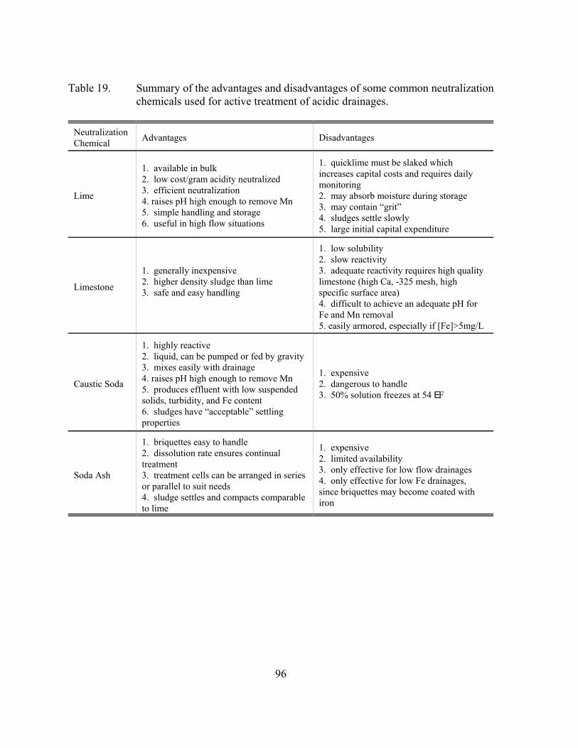
96
Table 19. Summary of the advantages and disadvantages of some common neutralizationchemicals used for active treatment of acidic drainages.
NeutralizationChemical Advantages Disadvantages
Lime
1. available in bulk2. low cost/gram acidity neutralized3. efficient neutralization4. raises pH high enough to remove Mn 5. simple handling and storage6. useful in high flow situations
1. quicklime must be slaked whichincreases capital costs and requires dailymonitoring2. may absorb moisture during storage3. may contain “grit”4. sludges settle slowly5. large initial capital expenditure
Limestone
1. generally inexpensive2. higher density sludge than lime3. safe and easy handling
1. low solubility2. slow reactivity3. adequate reactivity requires high qualitylimestone (high Ca, -325 mesh, highspecific surface area)4. difficult to achieve an adequate pH forFe and Mn removal5. easily armored, especially if [Fe]>5mg/L
Caustic Soda
1. highly reactive2. liquid, can be pumped or fed by gravity3. mixes easily with drainage4. raises pH high enough to remove Mn5. produces effluent with low suspendedsolids, turbidity, and Fe content6. sludges have “acceptable” settlingproperties
1. expensive2. dangerous to handle3. 50% solution freezes at 54 EF
Soda Ash
1. briquettes easy to handle2. dissolution rate ensures continualtreatment3. treatment cells can be arranged in seriesor parallel to suit needs4. sludge settles and compacts comparableto lime
1. expensive2. limited availability3. only effective for low flow drainages4. only effective for low Fe drainages,since briquettes may become coated withiron
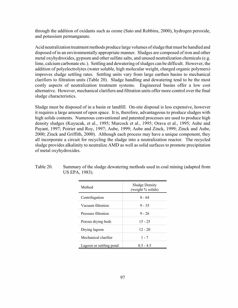
97
through the addition of oxidants such as ozone (Sato and Robbins, 2000), hydrogen peroxide,and potassium permanganate.
Acid neutralization treatment methods produce large volumes of sludge that must be handled anddisposed of in an environmentally appropriate manner. Sludges are composed of iron and othermetal oxyhydroxides, gypsum and other sulfate salts, and unused neutralization chemicals (e.g.lime, calcium carbonate etc.). Settling and dewatering of sludges can be difficult. However, theaddition of polyelectrolytes (water soluble, high molecular weight, charged organic polymers)improves sludge settling rates. Settling units vary from large earthen basins to mechanicalclarifiers to filtration units (Table 20). Sludge handling and dewatering tend to be the mostcostly aspects of neutralization treatment systems. Engineered basins offer a low costalternative. However, mechanical clarifiers and filtration units offer more control over the finalsludge characteristics.
Sludge must be disposed of in a basin or landfill. On-site disposal is less expensive, howeverit requires a large amount of open space. It is, therefore, advantageous to produce sludges withhigh solids contents. Numerous conventional and patented processes are used to produce highdensity sludges (Kuyucak, et al., 1995; Murcock et al., 1995; Orava et al., 1995; Aube andPayant, 1997; Poirier and Roy, 1997; Aube, 1999; Aube and Zinck, 1999; Zinck and Aube,2000; Zinck and Griffith, 2000). Although each process may have a unique component, theyall incorporate a circuit for recycling the sludge into a neutralization reactor. The recycledsludge provides alkalinity to neutralize AMD as well as solid surfaces to promote precipitationof metal oxyhydroxides.
Table 20. Summary of the sludge dewatering methods used in coal mining (adapted fromUS EPA, 1983).
Method Sludge Density(weight % solids)
Centrifugation 8 - 64
Vacuum filtration 9 - 35
Pressure filtration 9 - 26
Porous drying beds 15 - 25
Drying lagoon 12 - 20
Mechanical clarifier 1 - 7
Lagoon or settling pond 0.5 - 4.5
98
An alternative method to produce a more innocuous sludge is known as the “Ferrite Process”(Choung et al., 2000; McKinnon et al., 2000). Ferrites are magnetic iron oxide minerals thatincorporate divalent metals into their crystal lattice, MFe2O4. They can be produced by heatingaerated sludges to approximately 65 EC. The sludge must have a ferric to ferrous iron ratio ofapproximately 1.75, which can be attained by adding FeSO4C7H2O. The optimum pH is between9 and 11.
Ferrites containing trace metals can be magnetically separated from the sludge, resulting in a lesshazardous sludge. A potential drawback to the Ferrite Process is that high levels of calcium inthe sludge will result in coprecipitation of calcite and/or gypsum. These precipitates interferewith ferrite crystal growth. Consequently, pH adjustments are made using NaOH and excesscalcium must be removed prior to ferrite production. Calcium removal involves additionalexpense. However, the commercial value of ferrites may offset the cost.
8.2. Chemical Precipitation Systems
In some systems, the lime treatment system may be followed by an additional circuit toprecipitate dissolved species as gypsum, sulfides, or ferric iron co-precipitates. In high sulfatedrainages, the lime-treated effluent tends to be supersaturated with respect to gypsum (CaSO4).Excess sulfate can be removed from solution by adding seed crystals of gypsum, which provideactive surfaces to catalyze precipitation (Smit, 2000). Precipitated gypsum is thickened, filtered,and removed as a waste product, or recycled as seed crystals.
Additional metal removal can be accomplished by taking advantage of the relatively lowsolubility of metal sulfides. The addition of sodium sulfide to the lime-treated effluent promotesmetal sulfide precipitation. As with the lime treatment circuit, a polymer can be added toimprove settling of fine-grained sulfides, which are usually removed using gravity filtration.
Ferric iron co-precipitation typically occurs prior to the neutralization step (Lapakko, 1993;Ericksen et al., 1999; Aube and Stroiazzo, 2000). This process can be used to remove dissolvedspecies (i.e. molybdenum and arsenic) that do not precipitate well using standard neutralizationmethods. Ferric iron is added to the raw drainage in the form of ferric sulfate. The pH of thesolution is adjusted to 4.5 to optimize co-precipitation. Solids are removed by standardtechniques and the clarified water can be sent on to the neutralization circuit for additionalmetals removal and polishing before discharge to the environment.
Finally, a unique chemical precipitation treatment system, in which heavy metals areencapsulated in a silica structure, is being developed (Mitchell and Atkinson, 1995; Mitchell andWheaton, 1999; Rybock et al., 1999; Mitchell et al., 2000). The primary reagent is a proprietarycalcium/silica-based powder, called KB-1TM. It can be applied dry or in a slurry, similar totypical neutralization reagents. The removal mechanism takes place in phases initiated bydifferent reagent components. One component raises the pH to precipitate metals. The secondcomponent polymerizes, incorporating metals into a silica matrix. Within this silica matrix,
99
metals precipitate as relatively coarse, dense particles, creating a sludge that is chemically stableunder normal environmental conditions.
8.3. Ion Exchange Technology
Ion exchange involves the interchange of ions between a solid medium and aqueous solution.The solid medium typically consists of monovalent ions electrostatically attracted to chargedfunctional groups on an inert, polymeric substrate (i.e. resin). Di- and trivalent ions in solutionare more strongly attracted to the charged functional groups than monovalent ions.Consequently, di- and trivalent ions replace monovalent ions on the resin, releasing themonovalent species to solution. Water softening is the most common example of ion exchange,where dissolved calcium and magnesium ions exchange with sodium ions on the ion exchangeresin.
The long-term effectiveness of an ion exchange resin is determined by the density of functionalgroups, and therefore the concentration of monovalent ions, on the resin. Once all themonovalent ions on the resin have been replaced, the ion exchange resin will be renderedineffective. However, ion exchange resins are easily regenerated by periodically back flushingthe system with a strong acid, base, or salt solution. Waste water produced by regeneration mustalso be treated and disposed of properly. The higher the dissolved solids concentration, the morefrequently the exchange resins will need to be regenerated.
Ion exchange resins have been shown to remove trace metals and anions from problematic minedrainages. Dissolved di- and trivalent metal ions are removed from solution and exchanged formonovalent ions, typically sodium or hydrogen. Dissolved anions, such as sulfate and arsenate,can also be removed using anion exchange resins. However, high calcium and sulfateconcentrations typical of most mine drainages result in the need for frequent resin regeneration.This potential drawback has been avoided in more complicated treatment systems, where apretreatment step removes some of the dissolved solid load prior to the ion exchange step.
8.3.1. The GYP-CIX Process
Several ion exchange processes have been developed to treat mine drainages. The GYP-CIXprocess has been particularly promising in the treatment of drainages with elevated calcium andsulfate levels (Bowell, 2000). It uses a series of different ion exchange resins to remove bothcations and anions from low acidity mine water without pretreatment (Robertson and Rohrs,1995). In the first stage, calcium is removed by a strong acid cation exchange bed. This resultsin a strongly acidic solution, which is passed through an anion exchange unit to remove sulfateand arsenate. The anion exchange unit releases hydroxide ions, which neutralizes the solution.The cation exchange bed can be regenerated using sulfuric acid, which is neutralized with limeto precipitate gypsum and metal hydroxides. Similarly, the anion resin is regenerated with alime solution, which also precipitates gypsum. These gypsum sludges are similar to thoseproduced by typical neutralization treatment systems and can be disposed of in the same manner.
100
The GYP-CIX process has been used to treat water from the Berkeley Pit, Butte, MT withencouraging results (Table 21; Bowell, 2000).
8.3.2. BIO-FIX Beads
In the late 1980s, the US Bureau of Mines developed a porous polymeric bead to remove metalsfrom mining-related waste waters (Bennett and Jeffers, 1990; USBM, 1990; Bennett et al., 1991;Jeffers et al., 1992). Nonliving biomass (i.e. sphagnum moss) was immobilized in a polysulfonematrix to create a biomass-foam immobilized extractant (BIO-FIX) bead. Laboratory and fieldtests showed that the nonliving biomass in BIO-FIX beads effectively adsorbed heavy metalscommonly found in mine drainages (Bennet and Jeffers, 1990; USBM, 1990; Bennett et al.,1991; Jeffers et al., 1992).
One of the advantages of BIO-FIX beads is that they are easy to handle and can be used inconventional processing equipment without producing sludge. They are less cumbersomecompared to living biomass treatment systems because they do not require additional nutrientsor special conditions. Since the biomass is incorporated into a synthetic matrix (i.e. bead),separating the metal-laden biomass from the treated water can be accomplished easily.
Laboratory tests have established the stability of BIO-FIX beads for a wide range of pH values,flow rates, and treatment volumes (Bennet and Jeffers, 1990; Bennett et al., 1991). High metalremoval efficiencies were demonstrated in four field-scale tests using two different treatmentapproaches (Table 22). While maintenance requirements for these tests were generally low, highsuspended solid loads resulted in plugging problems (Jeffers et al., 1992). Although thelaboratory and field tests have demonstrated effective metal removal in the pH range of 3 - 8,it is not certain how effective metal removal would be in a strongly acidic mine drainage(Bennett et al., 1991; Parker and Robertson, 1998). It should also be noted that BIO-FIX beadtreatment does not provide alkalinity or increase drainage pH.
8.3.3. Zeolites and Selective Chelating Resins
Not all ion exchange materials consist of polymeric resins. Naturally occurring zeolites alsoexhibit cation exchange characteristics (Leppert, 1990; Gussmann et al., 1991; Vos and O'Hearn,1993; Schultze et al., 1994; Riveros, 1995; Gilbert et al., 1999). The crystal structure of naturalzeolites produce negative surface charges that attract cations. Structural differences betweenzeolites result in variable affinities for different metal ions. Therefore, zeolites should beselected based on site-specific drainage water chemistry and metal removal needs. Advantagesof using zeolites as ion exchangers include high physical integrity and loading capacity.However, substantial desorption of sodium, potassium, calcium or other metals into solution mayprove to be a major disadvantage. Another disadvantage of natural zeolites is that in practicethey cannot be regenerated and must be replaced regularly.
101
Table 21. The GYP-CIX process resulted in elevated pH and decreased levels of Ca, Mg,Fe, Mn, Cu, Zn, and SO4 in waters from the Berkeley Pit, Butte, MT (fromBowell, 2000).
Concentrations (mg/L,unless noted) Untreated GYP-CIX
pH (su) 2.7 8.0
Ca 490 50
Mg 420 20
Na 70 50
Fe 1100 <0.1
Mn 182 <0.1
Cu 186 <0.1
Zn 550 <0.1
SO4 8000 200
Table 22. Two different treatment approaches have been used to demonstrate metalremoval by BIO-FIX beads in four field-scale tests (Bennet and Jeffers, 1990;USBM, 1990; Bennett et al., 1991).
Parameter
PercentRemoval Treatment Approach Met Discharge
Limits?
Cd 90 low-maintenance troughs U
Co 94 3-column circuit U
Cu 99 3-column circuit; low-maintenancetroughs U
Fe >83 3-column circuit; low-maintenancetroughs in 2 out of 3 field tests
Mn >97 3-column circuit U
Ni 96 3-column circuit U
Pb 18 low-maintenance troughs
102
Zn >77 3-column circuit; low-maintenancetroughs
Selective chelating resins and synthetic zeolites have also been investigated as ion exchangematerials. However, these materials tend to be degraded at low pH typical of most minedrainages. Furthermore, iron interferes with their ion exchange capacities. One example of achelating resin that may have application to mine drainage treatment is the Octolig® treatmentsystem (Metre-General Inc., 2000). Metal immobilization occurs via chelation by ligandsbound to silica gel (resin). These ligands are reported to be highly selective for metals withoutretaining “benign” ions such as sodium, potassium, or calcium. This selectivity results ineffluent metal concentrations in the parts per billion level.
The Octolig® resin is insoluble and stable at a range of pH values from 0.5 to 10.5 andtemperatures from 0EC to 80EC (Metre-General Inc., 2000). It comes in packed columns from12 to 42 inches in diameter. The 42 inch columns can treat up to 25 gpm of water. For largerflows, the columns are arranged in parallel. Pretreatment precipitation or filtration circuits canalso be added, particularly if the drainage contains high levels of heavy metals. Fielddemonstrations of the Octolig® treatment system have taken place at a Colorado gold mine, theBerkeley Pit in Montana, the Summitville mine in Colorado, and the Leadville drainage tunnelin Colorado (Metre-General Inc., 2000; Appendix 7).
8.4. Membrane Filtration
Reverse osmosis can be applied to a wide variety of water purification needs. Commonly, it isused to desalinate seawater and brackish water to produce potable water. It has also been usedto treat problematic mine drainages (Sastri and Ashbrook, 1976; Blackshaw et al., 1983;Awadalla and Hazlett, 1992; Stewart et al., 1997; Berg and Arthur, 1999; Bowell, 2000; HWProcess, 2000). Membrane filtration techniques purify water by forcing water under pressurethrough membranes that are impervious to certain dissolved species. Several membranefiltration techniques, as determined by membrane pore size, have been used world-wide. Theexact technique used depends upon water usage requirements (Table 23).
Table 23. Summary of membrane filtration techniques based on operation parameters andwater usage.
Filtration Technique Pore Radius(nm)
Operating Pressure(MPa)
Potential Applications for ProblematicMine Drainages
Reverse osmosis <1.5 2.7 - 10.3 removal of mono- and divalent salts
Nanofiltration 1.5 - 2.5 1.0 - 2.7 removal of divalent salts
Ultrafiltration 2.5 - 50.0 0.35 - 1.4 removal of colloids and fine particles
103
Microfiltration 100 - 10000 0.04 - 0.35 filtration of fine particles
Reverse osmosis separates mono- and divalent salts from water through the application ofpressure that exceeds the osmotic pressure of the drainage. Flow through the membrane will beproportional to the net applied pressure and the natural osmotic pressure. Dissolved solids areretained in a brine, which requires special disposal (e.g. lime neutralization).
Advantages of reverse osmosis include removal of both dissolved inorganic and organiccontaminants, a simple modular configuration, minimal space requirement, and continuousoperation. However, water chemistry typical of most mine drainages may lead to severalproblems. High levels of dissolved species (i.e. iron, calcium, and sulfate) can result in; (1) highosmotic pressures, which lower the effective driving force for separation, (2) deterioration ofproduct water quality, (3) shortened membrane life, and (4) precipitation of sparingly solublesalts (i.e. gypsum, metal hydroxides), which can lead to membrane fouling and increasedresistance to permeation.
Although the lower pH typical of many mining effluents may improve efficiency, it alsocontributes to the deterioration of the membrane. Reverse osmosis is also an expensivetechnology relative to more conventional chemical precipitation techniques (section 8.6).Consequently, reverse osmosis is usually only used as a pre- or post-treatment step to removecontaminants not removed by more conventional means.
8.5. Biological Sulfate Reduction Treatment Systems
Biological sulfate reduction systems represent one alternative to typical neutralization systemsused to treat contaminated ground waters (Nakamura, 1988; Dvorak et al., 1991; Boreck et al.,1995; de Vegt et al., 1997; Diaz et al., 1997; Rowley et al., 1997; de Vegt et al., 1998; Dijkmanet al., 1999; Kolmert et al., 1999). These systems utilize sulfate reducing bacteria to consumedissolved sulfate and acid, producing hydrogen sulfide gas and alkalinity. In order for sulfatereduction to occur, however, a dissolved species capable of donating electrons (i.e. energysource) must be available. Both hydrogen gas (reaction 16) and simple organic compounds(reaction 17) can be used for this purpose and both types of systems have been used to treatmining effluents (Boreck et al., 1995; Diaz et al., 1997; Dijkman et al., 1999).
SO42! + 4H2 +2H+ 6 H2S + 4H2O (16)
3SO42! + 2C2H5OH + 2H+ 6 3H2S + 4HCO3
! + 2H2O (17)
Hydrogen is generally used in systems with high sulfate loads. However, hydrogen must beproduced on site by cracking methanol or using a natural gas steam reformer. Organic electrondonors are preferred for smaller sulfate loads.
104
Contaminated ground water must be pumped to a surface biological reactor, where sulfatereduction takes place. Although systems vary, they generally proceed in a series of stepsbeginning with sulfate reduction. Alkalinity generated during the reaction helps consume acidityin the waste stream, while biologically produced hydrogen sulfide reacts with dissolved metals(reaction 18):
H2S + Me2+ 6 MeS(s) + 2H+ (18)
where, Me2+ represents a dissolved metal. Subsequent steps allow metal sulfide precipitates tosettle out of solution. Some systems utilize a “chemical loop,” which enables selectiveprecipitation of metals (Nakamura, 1988; Dvorak et al., 1991; de Vegt et al., 1997, 1998).
As a final step, some biological treatment systems recover elemental sulfide as a saleableproduct. This is accomplished by oxidizing either gaseous or dissolved hydrogen sulfide toelemental sulfur. One documented method utilizes aerobic sulfur bacteria to oxidize excessdissolved hydrogen sulfide to elemental sulfur (reaction 19):
2HS! + O2 6 S0 + OH! (19)
A second method utilizes the two step Claus Process (reactions 20 and 21),:
2H2S + 3O2 6 2SO2 + 2H2O (20)
2H2S + SO2 6 3S0 + 2H2O (21)
where hydrogen sulfide is stripped from metal sulfides in the sludge.
Biological sulfate reducing treatment systems have the potential to effectively remove sulfateand metals from ground waters contaminated by mining wastes. Biological treatment systemsare advantageous over traditional neutralization systems because; 1) lower levels of sulfate, iron,and other metal can be achieved, 2) it produces a relatively innocuous sludge that settles rapidly,and 3) organic waste materials (e.g. municipal sludge) can be used as the electron donor. Sulfatereducing treatment systems have an additional advantage in that saleable elemental sulfur canbe recovered, making these systems more economical.
Despite these advantages, biological sulfate reducing treatment systems can be fragile. Sulfatereducing bacteria require an anaerobic and pH neutral environment to effectively reducedissolved sulfate to hydrogen sulfide. Most ground waters contaminated by mining wastes areanaerobic, satisfying the first requirement. However, these waters tend to be acidic rather thanneutral. Acidic influents require neutralization prior to entering the sulfate reducing reactors.The addition of neutralization circuits to treatment system design increases capitol and operatingcosts, as well as creating additional sludge disposal issues.
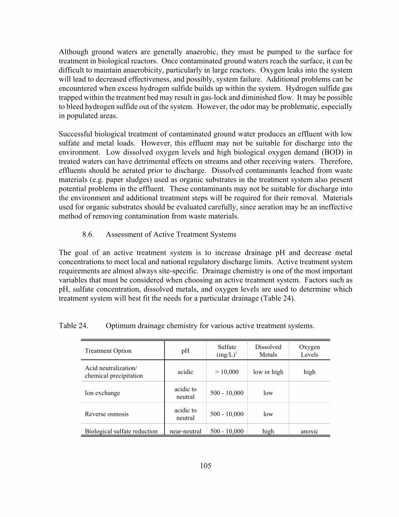
105
Although ground waters are generally anaerobic, they must be pumped to the surface fortreatment in biological reactors. Once contaminated ground waters reach the surface, it can bedifficult to maintain anaerobicity, particularly in large reactors. Oxygen leaks into the systemwill lead to decreased effectiveness, and possibly, system failure. Additional problems can beencountered when excess hydrogen sulfide builds up within the system. Hydrogen sulfide gastrapped within the treatment bed may result in gas-lock and diminished flow. It may be possibleto bleed hydrogen sulfide out of the system. However, the odor may be problematic, especiallyin populated areas.
Successful biological treatment of contaminated ground water produces an effluent with lowsulfate and metal loads. However, this effluent may not be suitable for discharge into theenvironment. Low dissolved oxygen levels and high biological oxygen demand (BOD) intreated waters can have detrimental effects on streams and other receiving waters. Therefore,effluents should be aerated prior to discharge. Dissolved contaminants leached from wastematerials (e.g. paper sludges) used as organic substrates in the treatment system also presentpotential problems in the effluent. These contaminants may not be suitable for discharge intothe environment and additional treatment steps will be required for their removal. Materialsused for organic substrates should be evaluated carefully, since aeration may be an ineffectivemethod of removing contamination from waste materials.
8.6. Assessment of Active Treatment Systems
The goal of an active treatment system is to increase drainage pH and decrease metalconcentrations to meet local and national regulatory discharge limits. Active treatment systemrequirements are almost always site-specific. Drainage chemistry is one of the most importantvariables that must be considered when choosing an active treatment system. Factors such aspH, sulfate concentration, dissolved metals, and oxygen levels are used to determine whichtreatment system will best fit the needs for a particular drainage (Table 24).
Table 24. Optimum drainage chemistry for various active treatment systems.
Treatment Option pH Sulfate(mg/L)1
DissolvedMetals
OxygenLevels
Acid neutralization/chemical precipitation acidic > 10,000 low or high high
Ion exchange acidic toneutral 500 - 10,000 low
Reverse osmosis acidic toneutral 500 - 10,000 low
Biological sulfate reduction near-neutral 500 - 10,000 high anoxic
106
Other variables include site accessability, the amount of available space for process equipmentand sludge disposal, climate, and local discharge limits. In some situations, it may be necessaryto use a combination of active treatment systems to optimize treatment and/or meet dischargelimits. Finally, sludge produced as a result of metals precipitation must meet Toxic ContaminantLeaching Protocol (TCLP) standards in order to be disposed of in a municipal landfill. Ifsludges do not meet these standards, they must be treated as hazardous waste, greatly increasingthe cost of handling and disposal.
8.7. Cost Comparison of Different Active Treatment Systems
Operational costs of active treatment systems vary depending on the choice of system, chemicalsand materials required, sludge handling and disposal, and site-specific considerations such astransportation costs. Additional precipitation circuits to remove metals also add to constructionand operational costs. However, these costs can be reduced if an economically valuable product,such as elemental sulfur, pyrite, or a specific metal, can be recovered from the waste stream.
Based on information collected from several North American treatment plants (Appendix 6),operational costs for acid neutralization plants are on the order of several dollars per thousandgallons treated (Table 25). One operation reported that chemicals accounted for approximatelytwo thirds of their operational costs (Aziz and Ferguson, 1997). Very little information wasavailable for design, capital, and construction costs for neutralization plants. Based oninformation provided for a single operation, the Argo Tunnel, CO, these costs are estimated at$5.8 million dollars.
Ultimately, the costs associated with an ion exchange treatment system depend upon thedissolved solids load in the drainage relative to the drainage quality that must be achieved (Table26). Due to the regeneration frequency required to remain effective, ion exchange systems tendto be cost prohibitive as a lone treatment for problematic mine drainage. However, in certainsituations, ion exchange systems may be cost effective. For example, ion exchange may be costeffective if the drainage in question contains high levels of metals that are difficult to removeby neutralization alone. In this case, an ion exchange circuit placed prior to neutralization canreduce the quantity of neutralization chemicals and associated expense that would otherwise berequired to meet discharge limits. Ion exchange should also be considered when very low waterquality standards must be met. In this situation, ion exchange is used as a polishing step afterneutralization but prior to discharge. Finally, extraction of economically valuable metals maymake ion exchange a viable and efficient treatment option.
As with ion exchange systems, the cost associated with a membrane filtration treatment system(i.e. reverse osmosis) depends upon the drainage chemistry relative to the quality of water thatmust be achieved to meet discharge limits (Table 26). No current mine drainage applicationsof reverse osmosis were identified during the course of this study. Past applications were used

107
to treat a specific mine drainage issue and were discontinued, presumably due to the high costof
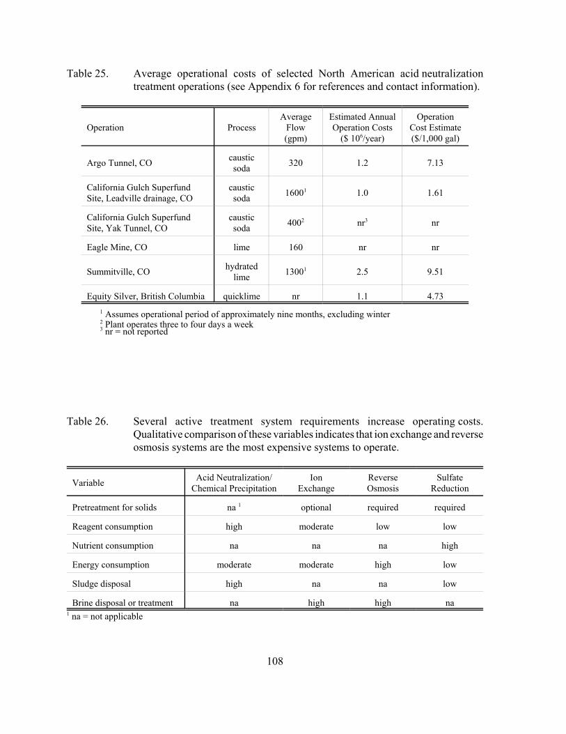
108
Table 25. Average operational costs of selected North American acid neutralizationtreatment operations (see Appendix 6 for references and contact information).
Operation ProcessAverage
Flow(gpm)
Estimated AnnualOperation Costs
($ 106/year)
OperationCost Estimate($/1,000 gal)
Argo Tunnel, CO causticsoda 320 1.2 7.13
California Gulch SuperfundSite, Leadville drainage, CO
causticsoda 16001 1.0 1.61
California Gulch SuperfundSite, Yak Tunnel, CO
causticsoda 4002 nr3 nr
Eagle Mine, CO lime 160 nr nr
Summitville, CO hydratedlime 13001 2.5 9.51
Equity Silver, British Columbia quicklime nr 1.1 4.731 Assumes operational period of approximately nine months, excluding winter2 Plant operates three to four days a week3 nr = not reported
Table 26. Several active treatment system requirements increase operating costs.Qualitative comparison of these variables indicates that ion exchange and reverseosmosis systems are the most expensive systems to operate.
Variable Acid Neutralization/Chemical Precipitation
IonExchange
ReverseOsmosis
SulfateReduction
Pretreatment for solids na 1 optional required required
Reagent consumption high moderate low low
Nutrient consumption na na na high
Energy consumption moderate moderate high low
Sludge disposal high na na low
Brine disposal or treatment na high high na1 na = not applicable
109
operation. High costs are largely due to high energy consumption and the need to dispose ofbrine wastes.
In general, biological treatment systems are the least expensive, but the most complicatedsystems to operate (Table 26). Only a few operational-scale examples of biological treatmentsystems for mining impacted ground water are reported here. Projected capital and annualoperating costs for the “Biosulphide Process” treatment system installed at the Britannia CopperMine, British Columbia were $2.2 million and $1 million, respectively (Rowley et al., 1997).The more recently applied THIOPAQ Process, used at Budelco Zinc Refinery, The Netherlandsand a pilot plant at Kennecott’s Bingham Canyon, Utah Copper Mine, is estimated to cost US$340/t of sulfate removed. Depending on the current market value, operating costs can bedecreased by adding a circuit to recover elemental sulfur for resale.
Cost comparisons between the various active treatment strategies are difficult to quantify. Thisis due, in part, to a lack of adequate cost analysis data. However, the validity of any suchcomparison would be questionable on the basis that these systems are employed to meet site-specific treatment needs. Comparisons are further complicated by the fact that one or more ofthese systems may be used in series to optimize conditions for a particular system or to meetlocal discharge requirements.
Qualitative comparisons can be made based on the various system requirements (Table 26).Pretreatment circuits and high energy consumption often result in high operational costs (Table27). Consequently, reverse osmosis and ion exchange systems tend to be more expensive thanacid neutralization alone. Sulfate reduction circuits are generally the least expensive becausethey require very little energy input and reagents can be regenerated on-site. In relative terms,annual operating costs for ion exchange and reverse osmosis systems may be as much as 30 -50% higher than a conventional acid neutralization system, while operation of a sulfate reductionsystem may cost as much as 50% less.
8.8. Application of Active Treatment Systems to Problematic Mine Drainages inMinnesota
8.8.1. AMAX/Kennecott Test Site
In 1976, AMAX Exploration, Inc. began construction of an exploration shaft near Babbitt,Minnesota. Six small test piles containing 62,000 tons of low grade copper-nickel DuluthComplex rock taken from an exploration shaft, were constructed. In 1982, Kennecott MiningCompany took over state leases for the prospect. In 1998 Kennecott reclaimed the site with theexception of the six test piles and the settling basin. The MN DNR assumed liability for the testpiles and as part of a NPDES permit had to establish an acceptable active treatment system forthe effluent from the piles. Treatment objectives were to develop a low maintenance, low costtreatment system that would reduce all metals in the drainage to less than 1 mg/L (Eger et al.,1993).
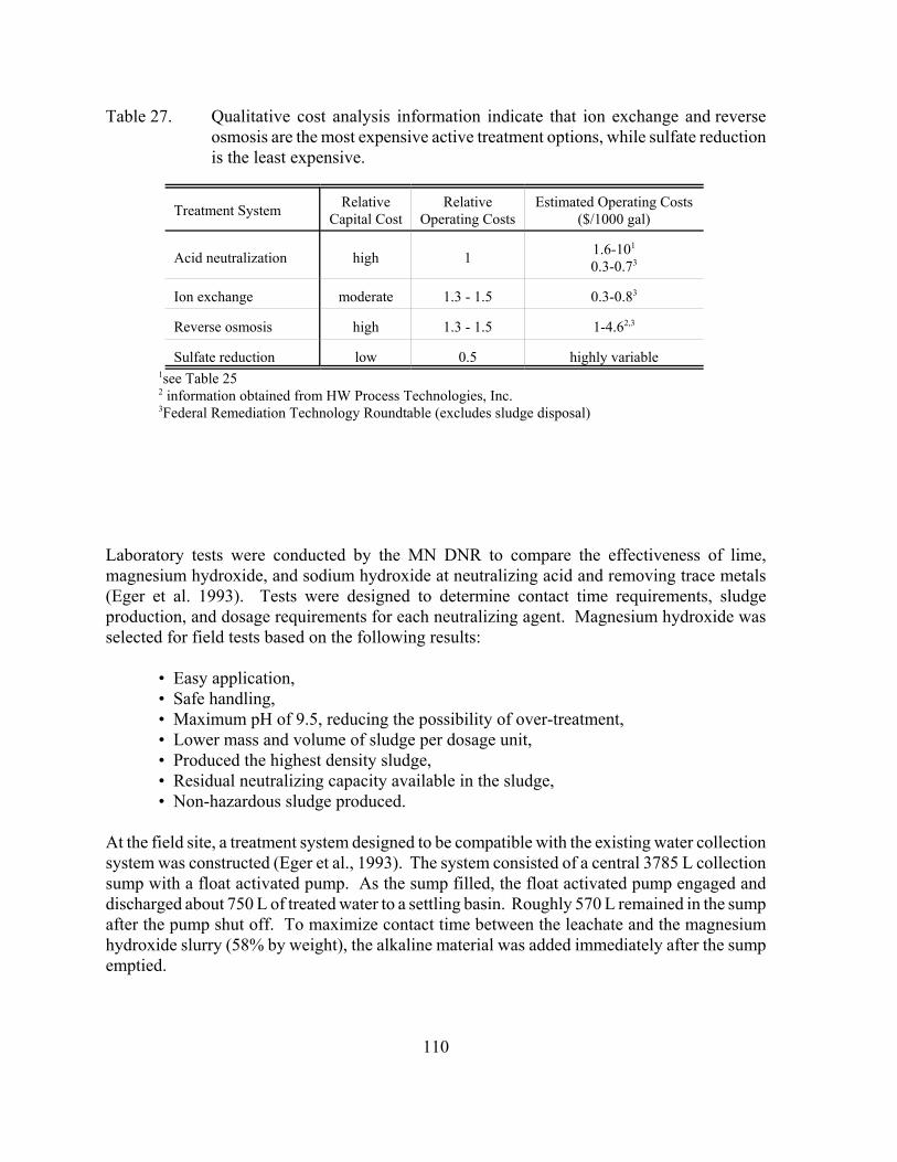
110
Table 27. Qualitative cost analysis information indicate that ion exchange and reverseosmosis are the most expensive active treatment options, while sulfate reductionis the least expensive.
Treatment System RelativeCapital Cost
RelativeOperating Costs
Estimated Operating Costs($/1000 gal)
Acid neutralization high 1 1.6-101
0.3-0.73
Ion exchange moderate 1.3 - 1.5 0.3-0.83
Reverse osmosis high 1.3 - 1.5 1-4.62,3
Sulfate reduction low 0.5 highly variable1see Table 252 information obtained from HW Process Technologies, Inc.3Federal Remediation Technology Roundtable (excludes sludge disposal)
Laboratory tests were conducted by the MN DNR to compare the effectiveness of lime,magnesium hydroxide, and sodium hydroxide at neutralizing acid and removing trace metals(Eger et al. 1993). Tests were designed to determine contact time requirements, sludgeproduction, and dosage requirements for each neutralizing agent. Magnesium hydroxide wasselected for field tests based on the following results:
• Easy application,• Safe handling,• Maximum pH of 9.5, reducing the possibility of over-treatment,• Lower mass and volume of sludge per dosage unit,• Produced the highest density sludge,• Residual neutralizing capacity available in the sludge,• Non-hazardous sludge produced.
At the field site, a treatment system designed to be compatible with the existing water collectionsystem was constructed (Eger et al., 1993). The system consisted of a central 3785 L collectionsump with a float activated pump. As the sump filled, the float activated pump engaged anddischarged about 750 L of treated water to a settling basin. Roughly 570 L remained in the sumpafter the pump shut off. To maximize contact time between the leachate and the magnesiumhydroxide slurry (58% by weight), the alkaline material was added immediately after the sumpemptied.
111
Based on the laboratory results, an initial magnesium hydroxide dose between 1.0 - 2.0 g/L wasused (Eger et al., 1993). By the end of the field season, this dose was increased to 2.2 g/L toprovide better treatment at high flow rates. Field results generally agreed with the laboratoryresults. When dosage and contact time (>6hr) were adequate, pH generally exceeded 8.0 andsuitable treatment was achieved. However, treatment efficiency decreased, particularly in termsof nickel removal, as flow rates increased above 3.7 L/min. Overall, it was concluded thatmagnesium hydroxide could effectively neutralize acid and remove metals from problematicmine drainages (Eger et al., 1993).
8.8.2. MN DNR Field Research Site, Hibbing, MN
In 1996, the magnesium hydroxide treatment technology developed at the AMAX/Kennecott sitewas applied to drainage from field experiments conducted at the MN DNR field research site inHibbing, Minnesota (Figure 6). Construction cost for the building and treatment system wereapproximately $95,000. The treatment plant operates continuously and is designed for a dailymaximum flow of 1.5 gpm (Table 28). Approximately 60,000-80,000 gallons of waste wateris treated annually at a cost of approximately $12,000 (MN DNR, unpublished data).
Drainage from field experiments is generally acidic, containing elevated levels of copper, nickel,cobalt, and zinc. Since effluent from the treatment plant discharges into the Hibbing sewersystem, it must meet local discharge limits (Table 29). Sludge produced during the treatmentprocess must also meet TCLP limits for landfill disposal.
8.8.3. Dunka Mine Site
Active treatment of problematic mine drainages is currently used at LTV Steel MiningCompany’s Dunka Mine Site near Babbitt, Minnesota. More than 50 million tons of sulfidebearing rock is stockpiled at this site. The most recent report indicates total flow from thestockpiles ranges from 50 to 200 million gallons per year. Drainage seeping from the stockpilesis generally near-neutral, however, pH values as low as 4.5 have been reported. Despite theneutral drainage pH, copper, nickel, cobalt, and zinc concentrations exceed ambient levels by10 to 10,000 times.
At present, drainage from these stockpiles is collected and discharged into wetland treatmentsystems. Outflow from the wetland treatment systems can be pumped to a collection basin forlime precipitation treatment to further reduce trace metal concentrations prior to discharge intoUnnamed Creek, and ultimately, Birch Lake. Each year, this system treats approximately threemillion liters of drainage at a cost of $200,000 (see A6.2 for description of the process).
Early in 2000, LTV Steel Mining Company announced that they would be closing theiroperation. In July 2000, LTV proposed re-issuance of their National Pollution DischargeElimination System (NPDES) permit to allow them to shut down the lime precipitation plant atDunka. In response, the MN DNR requested that the facilities remain in such a condition that
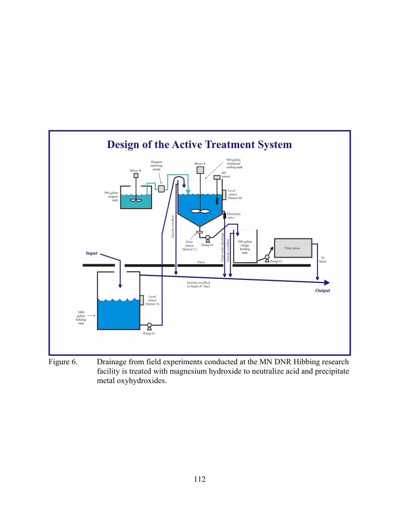
112
100 gallonreagent
tank
Mixer B
Mixer A
500 gallonsludgeholding
tank
Electronicvalve
Gra
vity
ove
rflo
w
500 gallontreatment/settling tank
Pump #2
Pump #3
Input
Output
Pump #1
Reagentmetering
pump
FloorTo
basin
Gravity overflowto basin (4" line)
pHsensor
Cle
an w
ater
dis
char
ge
Gra
vity
ove
rflo
w
Levelsensor
(Sensor A)
Flowsensor
(Sencor C)
1000gallon
holdingtank
Levelsensor
(Sensor B)
Design of the Active Treatment System
Filter press
Figure 6. Drainage from field experiments conducted at the MN DNR Hibbing researchfacility is treated with magnesium hydroxide to neutralize acid and precipitatemetal oxyhydroxides.
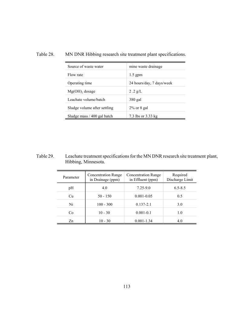
113
Table 28. MN DNR Hibbing research site treatment plant specifications.
Source of waste water mine waste drainage
Flow rate 1.5 gpm
Operating time 24 hours/day, 7 days/week
Mg(OH)2 dosage 2 .2 g/L
Leachate volume/batch 380 gal
Sludge volume after settling 2% or 8 gal
Sludge mass / 400 gal batch 7.3 lbs or 3.33 kg
Table 29. Leachate treatment specifications for the MN DNR research site treatment plant,Hibbing, Minnesota.
Parameter Concentration Rangein Drainage (ppm)
Concentration Rangein Effluent (ppm)
RequiredDischarge Limit
pH 4.0 7.25-9.0 6.5-8.5
Cu 50 - 150 0.001-0.05 0.5
Ni 100 - 300 0.137-2.1 3.0
Co 10 - 30 0.001-0.1 1.0
Zn 10 - 30 0.001-1.34 4.0
114
operation of the treatment plant could resume on short notice should the wetland treatmentsystems fail or if water quality standards in Unnamed Creek are exceeded. Both requests weregranted, and the Minnesota Pollution Control Agency reissued LTV’s NPDES permit in August2000 (Permit MN 0042579).
8.9. Active Treatment References
Aube, B.C. 1999. Innovative modifications to High Density Sludge Process. In: Mining andthe Environment Conf. Proc., Sudbury, Ontario, Sept. 13-17, 3, pg 1103-1112.
Aube, B.; Payant, S. 1997. The GECO process: a new high density sludge treatment for AMD.In: Proc. 4th Internat. Conf. on Acid Rock Drainage (ICARD), Vancouver, British Columbia,May 31-June 6, 1, pg 165-179.
Aube, B.C.; Stroiazzo, J. 2000. Molybdenum treatment at Brenda Mines. In: Proc. of the 5th
Internat. Conf. on Acid Rock Drainage (ICARD), Denver, CO, May 21-24, 2, pg 1113-1119.
Aube, B.C.; Zinck, J.M. 1999. Comparison of AMD treatment processes and their impact onsludge characteristics. In: Mining and the Environment Conf. Proc., Sudbury, Ontario, Sept.13-17, 1, pg 261-270.
Awadalla, F.T.; Hazlett, J.D. 1992. Application of membranes for the treatment of mining andmetallurgical effluents. Proc. Internat. Symp. on Waste Processing and Recycling in Mining andMetallurgical Industries, Edmonton, Alberta, August 23-27, pg 87-103.
Aziz, M.L.; Ferguson, K.D. 1997. Equity silver mine- integrated case study. In: Proc. 4th
Internat. Conf. on Acid Rock Drainage (ICARD), Vancouver, British Columbia, May 31-June6, 1, pg 181.
Bennett, P.G.; Ferguson, C.R.; Jeffers, T.H. 1991. Biological treatment of acid mine waters -case studies. In: Proc. 2nd Internat. Conf. on the Abatement of Acidic Drainage, Montreal,Canada. Sept. 16-18, 1, pg 283-300.
Bennett, P.G.; Jeffers, T.H. 1990. Removal of metal contaminants from a waste stream usingBIO-FIX beads containing sphagnum moss. Ch 35. In: Mining and Mineral Processing Wastes.Proc. Western Regional Symp. on Mining and Mineral Processing Wastes, Society for Mining,Metallurgy, and Exploration. Berkeley, CA, May 30 - June 1., pg 279-286.
Berg, G.; Arthur, B. 1999. Proposed mine water treatment in Wisconsin. In: Mining and theEnvironment Conf. Proc., Sudbury, Ontario, Sept. 13-17, 2, pg 627-634.
Blackshaw, G.L.; Pappano, A.W.; Thomas, G.E. Jr.; Cheng, S.Y. 1983. Pilot plant treatment ofacid mine drainage by reverse osmosis. Project Summary. EPA-600/S2-83-031, June.
115
Borek, S.L.; Dvorak, D.H.; Edenborn, H.M. 1995. Ability of cheese whey to support bacterialsulfate reduction in mine water treatment systems. In: Mining and the Environment Conf.Proc., Sudbury, ON, May 28-June 1, 3, pg 879-885.
Bowell, R.J., 2000. Sulphate and salt minerals: the problem of treating mine waste. Environ.Management, May, pg 11-13.
Choung, J.W.; Xu, Z.; Finch, J.A. 2000. Ambient temperature ferrite process for ARDtreatment. In: Proc. of the 5th Internat. Conf. on Acid Rock Drainage (ICARD), Denver, CO,May 21-24, 2, pg 1101-1111.
de Vegt, A.L.; Bayer, H.G.; Buisman, C.J. 1997. Biological sulfate removal and metal recoveryfrom mine waters. SME preprint 97-93, SME Annual Meeting, Denver, CO, Feb. 24-27.
deVegt, A.L.; Bayer, H.G.; Buisman, C.J. 1998. Biological sulfate removal and metal recoveryfrom mine waters. Mining Engineering, November, pg 67-70.
Diaz, M.A.; Monhemius, A.J.; Narayanan, A. 1997. Consecutive hydroxide-sulfideprecipitation treatment of acid rock drainage. In: Proc. 4th Internat. Conf. on Acid RockDrainage (ICARD), Vancouver, British Columbia, May 31-June 6, 3, pg 1179-1193.
Dijkman, H.; Buisman, C.J.N.; Bayer, H.G. 1999. Biotechnology in the mining andmetallurgical industries: cost savings through selective precipitation of metal sulfides. Presentedat Copper 99 Internat. Conf., Phoenix, AZ, Oct 10-13.
Dvorak, D.H.; Hedin, R.S.; Edenborn, H.M.; Gustafson, S.L. 1991. Treatment of metalcontaminated water using bacterial sulfate reduction: results from pilot-scale reactors. Proc. 2nd
Internat. Conf. on Acid Rock Drainage. Montreal, Quebec, Sept. 16-18, 1, pg 301-314.
Eger, P.; Melchert, G.; Antonson, D.; Wagner, J. 1993. Magnesium hydroxide as a treatmentfor acid mine drainage in northern Minnesota. Presented at the American Society for SurfaceMining and Reclamation Meeting, Spokane, WA, May 16-19.
Ericksen, L.P.; Walker, W.J.; Maslanka, C.K.; Burau, R.G.; Zasoski, R.J. 1999. Bi-phasicneutralization of evapoconcentrated acid mine drainage. In: Proc. 6th Internat. Conf. onTailings and Mine Waste ‘99, Fort Collins, CO, USA, Jan. 24-27, A.A. Balkema, Rotterdam,Netherlands, 808 p.
Federal Remediation Technology Roundtable. Remediation Technologies Screening Matrix andReference Guide, Version 3.0. www.frtr.gov/matrix2/section4.
116
Gilbert, J.S.; O’Meara, P.M.; Wildeman, T.R.; Crock, J.G.; Desborough, G.A. 1999.Adsorption capabilities of clinoptilolite relating to mine drainage remediation. In: Proc. 6th
Internat. Conf. on Tailings and Mine Waste ‘99, Fort Collins, CO, USA, Jan. 24-27, A.A.Balkema, Rotterdam, Netherlands, 808 p.
Gussmann, H.W.; Everett, D,J.; Du Plessis, J. 1991. The treatment of underground mine watersfor the removal of calcium and sulfates by a GYP-CIX process. 2nd Internat. Conf. on theAbatement of Acidic Drainage, Montreal, Sept. 16-18, 2, pg 377-390.
HW Process Technologies, Inc., 2000. Denver, CO. www.harrisonwestern.com.
Jeffers, T.H.; Bennett, P.G.; Corwin, R.R. 1992. Wastewater remediation using BIO-FIX beadtechnology. In: Proc. 2nd Internat. Conf. Environmental Issues and Waste Management inEnergy and Minerals Production. Balkema, Rotterdam. pg 1379-1387.
Kolmert, A.K.; Hallberg, K.B.; Johnson, D.B. 1999. Remediation of acid mine drainage bysulfate reducing bacteria in biofilm reactors. In: Phytoremediation and Innovative Strategies forSpecialized Remedial Applications. 5th Internat. In Situ and On Site Bioremediation Symp. SanDiego, CA, 19-22 April, pg 225-230.
Kuyucak, N.; Payant, S.; Sheremata, T. 1995. Improved lime neutralization process. In:Mining and the Environment Conf. Proc., Sudbury, ON, May 28-June 1, 1, pg 129-137.
Lapakko, K.A. 1993. Non-ferrous mine waste characterization project, Final Report. MN Dept.Nat. Resour., Division of Lands and Minerals. Saint Paul, MN. 98 p. plus appendices.
Leppert,D. 1990. Heavy metal sorption with clinoptilolite zeolite: Alternative for treatingcontaminated soil and water. Mining Engineering, pg 604-608.
McKinnon, W.; Choung, J.W.; Xu, Z.; Finch, J.A. 2000. Magnetic seed in ambient temperatureferrite process applied to acid mine drainage treatment. Environ. Sci. Technol., 34, pg 2576-2581.
Metre-General Inc. Advantages of Octolig® Treatment. Westminster, CO. www.octolig.com.
Miedecke, J.; Miller, S.; Gowen, M. Ritchie, I.; Johnston, J.; McBride, P. 1997. Remediationoptions (including Cu recovery by SX/EW) to reduce acid drainage from historical miningoperations at Mount Lyell, western Tasmania, Australia. In: Proc. 4th Internat. Conf. on AcidRock Drainage (ICARD), Vancouver, British Columbia, May 31-June 6, 4, pg 1451-1468.
Mitchell, P.B.; Atkinson, K. 1995. The treatment of ARD: a preliminary study of enhancedlime treatment by the coapplication of soluble sodium silicate. In: Mining and the EnvironmentConf. Proc., Sudbury, ON, May 28-June 1, 2, pg 467-476.
117
Mitchell, P.; Wheaton, A. 1999. From environmental burden to natural resource: new reagentsfor cost effective treatment of, and metal recovery from, acid rock drainage. In: Mining andthe Environment Conf. Proc., Sudbury, Ontario, Sept. 13-17, 3, pg 1231-1239.
Mitchell, P.; Potter, C.; Watkins, M. 2000. Treatment of ARD: field demonstration of silicamicro encapsulation technology and comparison with an existing caustic soda-based system.In: Proc. of the 5th Internat. Conf. on Acid Rock Drainage (ICARD), Denver, CO, May 21-24,2, pg 1035-1043.
Murdock, D.J.; Fox, J.R.W.; Bensley, J.G. 1995. Treatment of AMD by the HDS process. In:Mining and the Environment Conf. Proc., Sudbury, ON, May 28-June 1, 2, pg 431-439.
Nakamura, K. 1988. Biological metal removal from mine drainage. Mine Drainage andSurface Reclamation, Vol. 1, U.S. Bureau of Mines IC #9183, pg 274-278.
Nicolet Minerals Company. Crandon, WI. www.crandonmine.com.
Orava, D.; Hallam, C.E.; Swider, R. 1995. Evaluating alternative long-term strategies fortreatment of AMD. In: Mining and the Environment Conf. Proc., Sudbury, ON, May 28-June1, 2, pg 505-514.
Poirier, P.J.; Roy, M. 1997. AMD characterization and treatment at La Mine Doyon. In: Proc.4th Internat. Conf. on Tailings and Mine Waste ‘97, Fort Collins, CO, USA, Jan. 13-17, A.A.Balkema, Rotterdam, Netherlands, 788 p.
Riveros, P.A. 1995. Applications of ion exchangers to the treatment of AMD. In: Mining andthe Environment Conf. Proc., Sudbury, ON, May 28-June 1, 2, pg 441-449.
Robertson, A. MacG; Rohrs, R.G. 1995. Sulfate removal of AMD water after lime treatment. In: Mining and the Environment Conf. Proc., Sudbury, ON, May 28-June 1, 2, pg 575-586.
Rowley, M.V.; Warkentin, D.D.; Sicotte, V. 1997. Site demonstration of the biosulfide processat the former Britannia Mine. In: Proc. 4th Internat. Conf. on Acid Rock Drainage (ICARD),Vancouver, British Columbia, May 31-June 6, 4, pg 1531-1547.
Rybock, J.; Mitchell, P.; Wheaton, A.; Hopper, R. 1999. Silica micro encapsulation: aninnovative technology for the prevention and treatment of ARD. Proc. Randol Gold & SilverForum, ‘99. Denver, CO, May 12-14.
Sastri, V.S.; Ashbrook, A.W. 1976. Performance of some reverse osmosis membranes and theirapplication in the separation of metals in acid mine-water. Separation Science, 11, 2, pg 133-146.
118
Sato, M.; Robbins, E.I. 2000. Recovery/removal of metallic elements from acid mine drainageusing ozone. In: Proc. of the 5th Internat. Conf. on Acid Rock Drainage (ICARD), Denver, CO,May 21-24, 2, pg 1095-1100.
Schultze, L.E.; Zamzow, M.J.; Bremmer, P.R. 1994. AMD cleanup using natural zeolites. In:Internat. Land Reclamation and Mine Drainage Conf. and 3rd Internat. Conf. on the Abatementof Acidic Drainage, Pittsburgh, PA, April 24-29, 2, pg 341-347.
Smit, J.P., 2000. Potable water from sulphate polluted mine sources. Environ. Management,Nov., pg 7-9.
Stewart, D.; Norman, T.; Cordery-Cotter, S.; Kleiner, R.; Sweeney, E. 1997. Utilization of aceramic membrane for AMD treatment. In: Proc. 4th Internat. Conf. on Tailings and MineWaste ‘97, Fort Collins, CO, USA, Jan. 13-17, A.A. Balkema, Rotterdam, Netherlands, 788 p.
Tempel, R.N.; Lengke, M.F.; Ford, R.C.; Eastep, T.E.; Romig, B.R.; Clothier, G. 2000. Aquantitative approach to optimize chemical treatment of acid drainage using geochemicalreaction path modeling methods: Climax Mine, CO. In: Proc. of the 5th Internat. Conf. on AcidRock Drainage (ICARD), Denver, CO, May 21-24, 2, pg 1053-1058.
USBM. 1990. Removal of heavy metals from LTV Steel Mining Company water using BIO-FIX beads. U.S. Bureau of Mines, Salt Lake City Research Center, US Dept of the Interior. 13p.
US EPA. 1983. Design manual: Neutralization of acid mine drainage. U.S. EnvironmentalProtection Agency, Industrial Environmental Research Laboratory. EPA-600/2-83-001. 231p.
Vos, R.J.; O'Hearn, T.A. 1993. Use of zeolite to treat acid rock drainage from Britannia minesite.In: Proc. 17th Annual British Columbia Mine Reclamation Symposium: Mine Reclamation"Building Confidence". (Ed: Sponsored by: Mining Association of British Columbia) TheMinistry of Energy, Mines and Petroleum Resources, British Columbia, pg 223-232.
Willow, M.; tenBraak, C. 1999. Survey of three hard rock acid drainage treatment facilities inColorado. In: Proc. 6th Internat. Conf. on Tailings and Mine Waste ‘99, Fort Collins, CO, USA,Jan. 24-27, A.A. Balkema, Rotterdam, Netherlands, 808 p.
Zinck, J.M.; Aube, B.C. 2000. Optimization of lime treatment processes. CIM Bulletin, 93,1043, pg 98-105.
Zinck, J.M.; Griffith, W.F. 2000. An assessment of HDS-type lime treatment processes -efficiency and environmental impact. In: Proc. of the 5th Internat. Conf. on Acid Rock Drainage(ICARD), Denver, CO, May 21-24, 2, pg 1027 - 1034.
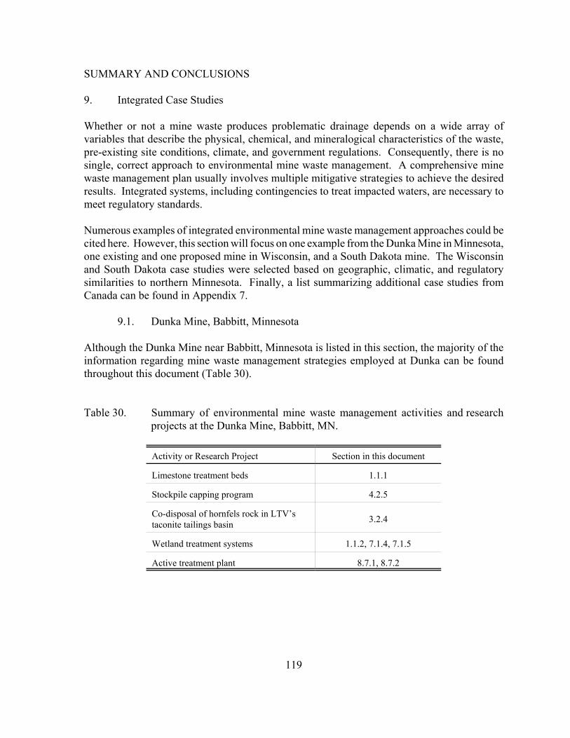
119
SUMMARY AND CONCLUSIONS
9. Integrated Case Studies
Whether or not a mine waste produces problematic drainage depends on a wide array ofvariables that describe the physical, chemical, and mineralogical characteristics of the waste,pre-existing site conditions, climate, and government regulations. Consequently, there is nosingle, correct approach to environmental mine waste management. A comprehensive minewaste management plan usually involves multiple mitigative strategies to achieve the desiredresults. Integrated systems, including contingencies to treat impacted waters, are necessary tomeet regulatory standards.
Numerous examples of integrated environmental mine waste management approaches could becited here. However, this section will focus on one example from the Dunka Mine in Minnesota,one existing and one proposed mine in Wisconsin, and a South Dakota mine. The Wisconsinand South Dakota case studies were selected based on geographic, climatic, and regulatorysimilarities to northern Minnesota. Finally, a list summarizing additional case studies fromCanada can be found in Appendix 7.
9.1. Dunka Mine, Babbitt, Minnesota
Although the Dunka Mine near Babbitt, Minnesota is listed in this section, the majority of theinformation regarding mine waste management strategies employed at Dunka can be foundthroughout this document (Table 30).
Table 30. Summary of environmental mine waste management activities and researchprojects at the Dunka Mine, Babbitt, MN.
Activity or Research Project Section in this document
Limestone treatment beds 1.1.1
Stockpile capping program 4.2.5
Co-disposal of hornfels rock in LTV’staconite tailings basin 3.2.4
Wetland treatment systems 1.1.2, 7.1.4, 7.1.5
Active treatment plant 8.7.1, 8.7.2
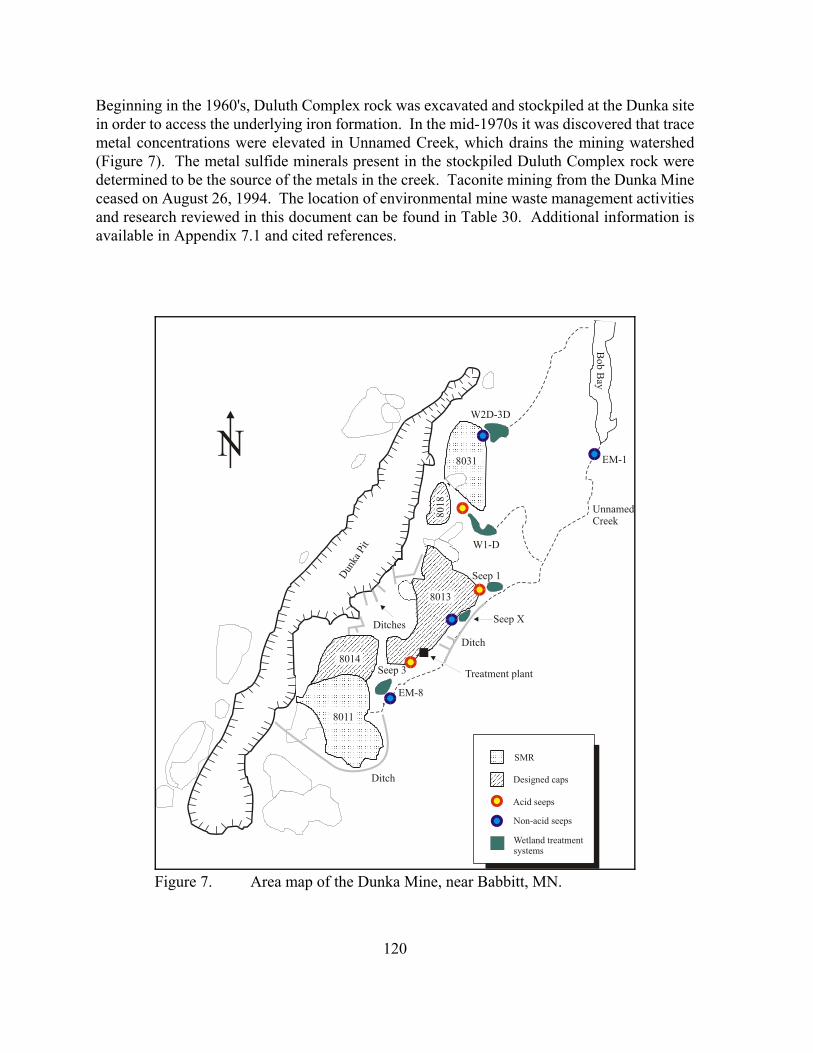
120
Bob B
ay
EM-1
Dunka
Pit
W2D-3D
W1-D
UnnamedCreek
Seep 1
Seep X
Seep 3
EM-8
8031
8018
8013
8011
8014
Designed caps
SMR
Wetland treatmentsystems
Acid seeps
Non-acid seeps
N
Ditches
Ditch
Ditch
Treatment plant
Figure 7. Area map of the Dunka Mine, near Babbitt, MN.
Beginning in the 1960's, Duluth Complex rock was excavated and stockpiled at the Dunka sitein order to access the underlying iron formation. In the mid-1970s it was discovered that tracemetal concentrations were elevated in Unnamed Creek, which drains the mining watershed(Figure 7). The metal sulfide minerals present in the stockpiled Duluth Complex rock weredetermined to be the source of the metals in the creek. Taconite mining from the Dunka Mineceased on August 26, 1994. The location of environmental mine waste management activitiesand research reviewed in this document can be found in Table 30. Additional information isavailable in Appendix 7.1 and cited references.
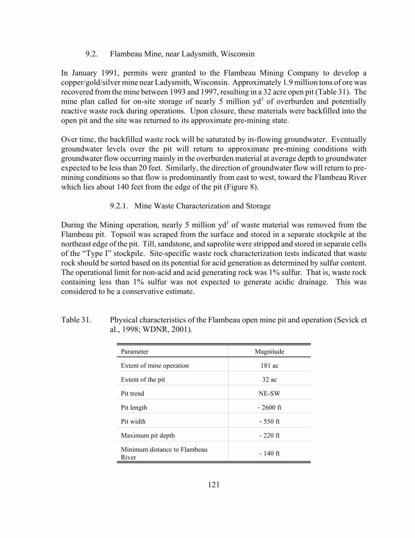
121
9.2. Flambeau Mine, near Ladysmith, Wisconsin
In January 1991, permits were granted to the Flambeau Mining Company to develop acopper/gold/silver mine near Ladysmith, Wisconsin. Approximately 1.9 million tons of ore wasrecovered from the mine between 1993 and 1997, resulting in a 32 acre open pit (Table 31). Themine plan called for on-site storage of nearly 5 million yd3 of overburden and potentiallyreactive waste rock during operations. Upon closure, these materials were backfilled into theopen pit and the site was returned to its approximate pre-mining state.
Over time, the backfilled waste rock will be saturated by in-flowing groundwater. Eventuallygroundwater levels over the pit will return to approximate pre-mining conditions withgroundwater flow occurring mainly in the overburden material at average depth to groundwaterexpected to be less than 20 feet. Similarly, the direction of groundwater flow will return to pre-mining conditions so that flow is predominantly from east to west, toward the Flambeau Riverwhich lies about 140 feet from the edge of the pit (Figure 8).
9.2.1. Mine Waste Characterization and Storage
During the Mining operation, nearly 5 million yd3 of waste material was removed from theFlambeau pit. Topsoil was scraped from the surface and stored in a separate stockpile at thenortheast edge of the pit. Till, sandstone, and saprolite were stripped and stored in separate cellsof the “Type I” stockpile. Site-specific waste rock characterization tests indicated that wasterock should be sorted based on its potential for acid generation as determined by sulfur content.The operational limit for non-acid and acid generating rock was 1% sulfur. That is, waste rockcontaining less than 1% sulfur was not expected to generate acidic drainage. This wasconsidered to be a conservative estimate.
Table 31. Physical characteristics of the Flambeau open mine pit and operation (Sevick etal., 1998; WDNR, 2001).
Parameter Magnitude
Extent of mine operation 181 ac
Extent of the pit 32 ac
Pit trend NE-SW
Pit length -2600 ft
Pit width -550 ft
Maximum pit depth -220 ft
Minimum distance to FlambeauRiver -140 ft
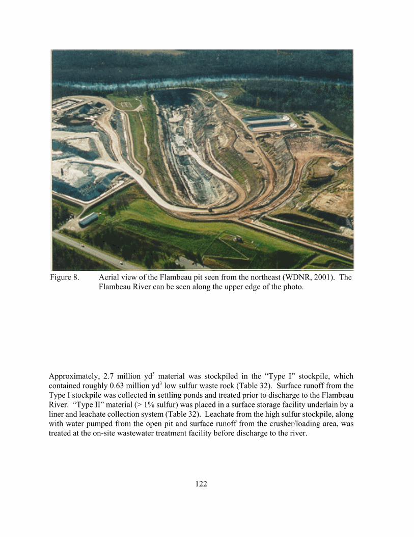
122
Figure 8. Aerial view of the Flambeau pit seen from the northeast (WDNR, 2001). TheFlambeau River can be seen along the upper edge of the photo.
Approximately, 2.7 million yd3 material was stockpiled in the “Type I” stockpile, whichcontained roughly 0.63 million yd3 low sulfur waste rock (Table 32). Surface runoff from theType I stockpile was collected in settling ponds and treated prior to discharge to the FlambeauRiver. “Type II” material (> 1% sulfur) was placed in a surface storage facility underlain by aliner and leachate collection system (Table 32). Leachate from the high sulfur stockpile, alongwith water pumped from the open pit and surface runoff from the crusher/loading area, wastreated at the on-site wastewater treatment facility before discharge to the river.
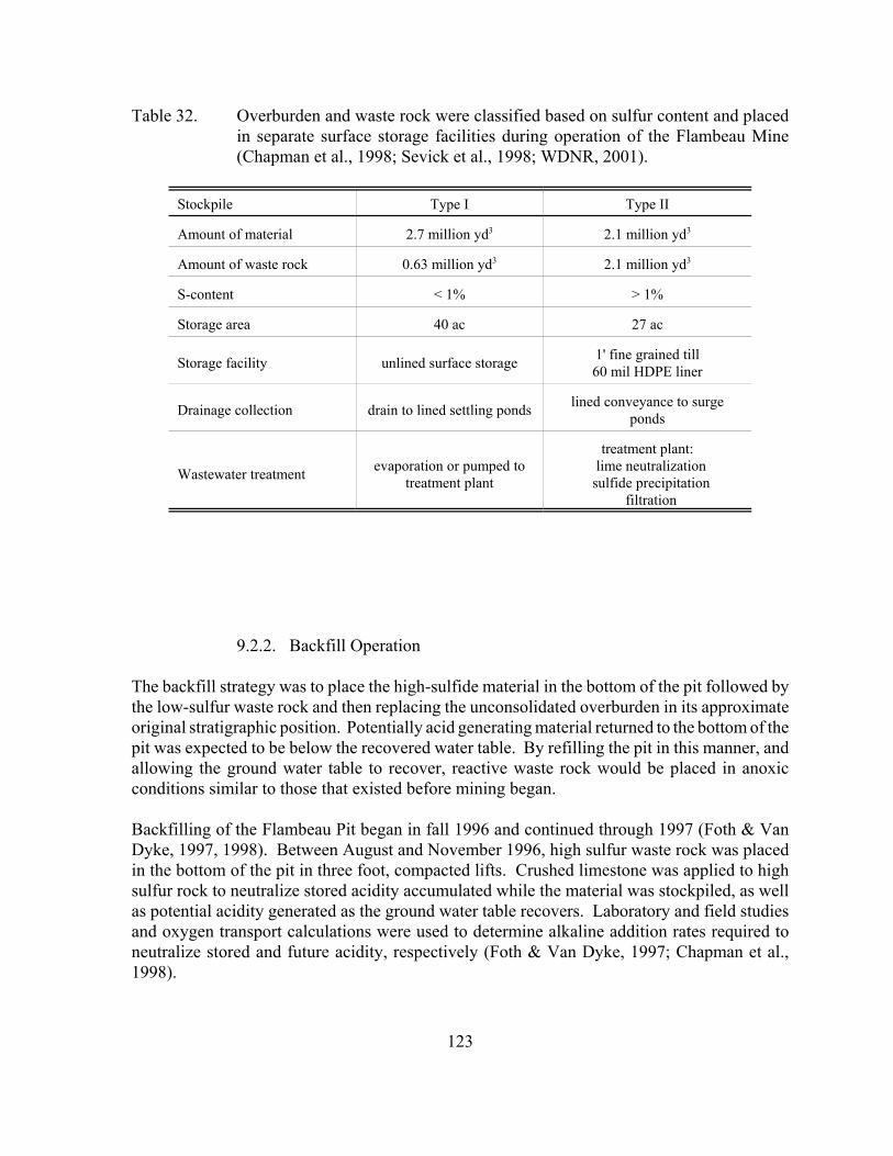
123
Table 32. Overburden and waste rock were classified based on sulfur content and placedin separate surface storage facilities during operation of the Flambeau Mine(Chapman et al., 1998; Sevick et al., 1998; WDNR, 2001).
Stockpile Type I Type II
Amount of material 2.7 million yd3 2.1 million yd3
Amount of waste rock 0.63 million yd3 2.1 million yd3
S-content < 1% > 1%
Storage area 40 ac 27 ac
Storage facility unlined surface storage 1' fine grained till60 mil HDPE liner
Drainage collection drain to lined settling ponds lined conveyance to surgeponds
Wastewater treatment evaporation or pumped totreatment plant
treatment plant: lime neutralization
sulfide precipitation filtration
9.2.2. Backfill Operation
The backfill strategy was to place the high-sulfide material in the bottom of the pit followed bythe low-sulfur waste rock and then replacing the unconsolidated overburden in its approximateoriginal stratigraphic position. Potentially acid generating material returned to the bottom of thepit was expected to be below the recovered water table. By refilling the pit in this manner, andallowing the ground water table to recover, reactive waste rock would be placed in anoxicconditions similar to those that existed before mining began.
Backfilling of the Flambeau Pit began in fall 1996 and continued through 1997 (Foth & VanDyke, 1997, 1998). Between August and November 1996, high sulfur waste rock was placedin the bottom of the pit in three foot, compacted lifts. Crushed limestone was applied to highsulfur rock to neutralize stored acidity accumulated while the material was stockpiled, as wellas potential acidity generated as the ground water table recovers. Laboratory and field studiesand oxygen transport calculations were used to determine alkaline addition rates required toneutralize stored and future acidity, respectively (Foth & Van Dyke, 1997; Chapman et al.,1998).
124
The rate of limestone addition for high sulfur rock that was excavated from the west end of thepit and immediately deposited in the east end ranged from 4.0 - 4.9 lb/ton. Application rates of20 lb/ton were used for stockpiled high sulfur rock backfill. In practice, limestone was appliedto the surface of each waste rock lift prior to its removal from the stockpile (Foth & Van Dyke,1998). Approximately 1.5 million pounds of crushed limestone was applied to the high sulfurrock during this portion of the backfill operation (Foth & Van Dyke, 1998). After placement ofthe high sulfur rock and limestone in the pit was completed, backfilling continued with lowsulfur waste rock amended with a limited amount of limestone, saprolite, sandstone, and till.
Surface reclamation of the site began in 1998 by regrading the land surface to its approximateoriginal contour. Stockpiled topsoil was spread over the site and vegetated to create grasslands,woodlands, and wetlands. Reclamation activities through 2000 included seeding, plug planting,tree planting, erosion control, mowing, invasive species control, trail construction, andprescribed burning (Flambeau Mining Co., 2001).
9.2.3. Environmental and Ground Water Monitoring
According to permit requirements, the Flambeau Mining Company must regularly monitorground water, backfill pore water, wetland, and Flambeau River water levels and quality inaddition to aquatic ecology characteristics (WDNR, 2001). As part of the permitting process,both hydrologic and geochemical modeling were used to characterize the potential impacts ofthe backfilled pit on the Flambeau River (Prickett et al., 1996; Foth and Van Dyke, 1997; Eng.Tech. Assoc. Inc., 1998). Hydrologic modeling indicated that it would take fifteen years forground water levels in the backfilled pit to recover (Eng. Tech. Assoc. Inc., 1998). Furthermore,calculations showed that the flux of backfill pore water to the river would be 6.5 x 10⁵ timeslower than the ten year, seven day, low flow for the river (Flambeau Mining Company, 2001).Consequently, it was assumed that backfill pore water quality would not have a measurableaffect on surface water quality. The October 2000 assessment concluded that regional groundwater flow, including backfill pore water, is indeed moving toward the Flambeau River asexpected (Flambeau Mining Company, 2001).
Ground water quality monitoring in nineteen wells has been conducted on a regular basis.Trends in backfill pore water chemistry indicate a calcium-magnesium-sulfate-carbonatedominated water in equilibrium with calcite and gypsum (Flambeau Mining Company, 2001).This equilibrium condition suggests that stored acidity in the backfill has been neutralized bylimestone. Major elements, pH, and alkalinity concentrations have been stable, although iron,manganese, and carbon dioxide levels are higher than anticipated (Flambeau Mining Company,2001). Concentrations of other metals, including copper, are similar to predicted values. Inthe October 2000 assessment, it was concluded that backfill pore water chemistry had stabilizedand was not affecting Flambeau River water quality.
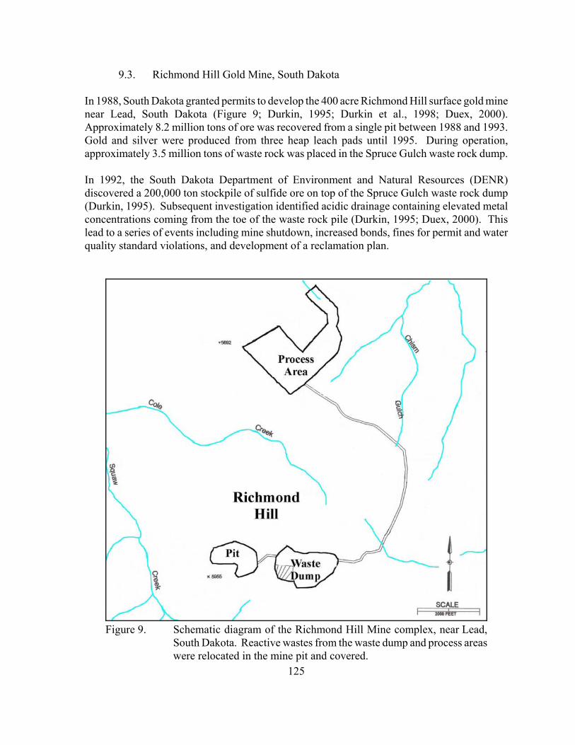
125
Figure 9. Schematic diagram of the Richmond Hill Mine complex, near Lead,South Dakota. Reactive wastes from the waste dump and process areaswere relocated in the mine pit and covered.
9.3. Richmond Hill Gold Mine, South Dakota
In 1988, South Dakota granted permits to develop the 400 acre Richmond Hill surface gold minenear Lead, South Dakota (Figure 9; Durkin, 1995; Durkin et al., 1998; Duex, 2000).Approximately 8.2 million tons of ore was recovered from a single pit between 1988 and 1993.Gold and silver were produced from three heap leach pads until 1995. During operation,approximately 3.5 million tons of waste rock was placed in the Spruce Gulch waste rock dump.
In 1992, the South Dakota Department of Environment and Natural Resources (DENR)discovered a 200,000 ton stockpile of sulfide ore on top of the Spruce Gulch waste rock dump(Durkin, 1995). Subsequent investigation identified acidic drainage containing elevated metalconcentrations coming from the toe of the waste rock pile (Durkin, 1995; Duex, 2000). Thislead to a series of events including mine shutdown, increased bonds, fines for permit and waterquality standard violations, and development of a reclamation plan.
126
9.3.1. Short-term Mitigation Measures
Short-term mitigation measures focused on collection and treatment of impacted waters (Durkin,1995; Durkin et al., 1998). Beginning in the spring of 1992, treatment and retention ponds wereconstructed to collect drainage from the waste rock depository. An anoxic limestone drain wasused for the initial treatment. However, it was quickly rendered ineffective by ferric hydroxidearmoring of the limestone. Subsequent treatment in the ponds utilized caustic soda toneutralization acid and precipitate metal hydroxides. After partial treatment, this water waspumped to an 80 million gallon storm water pond for storage, and ultimately, treatment in thewaste water treatment plant. A system of pumping wells was constructed within the retentionpond area to collect local impacted ground water within a near surface alluvial/colluvial aquifer.
Several other measures were taken to contain the reactive sulfide ore and inhibit furtheroxidation. In order to contain further drainage problems, the sulfide ore stockpile was movedto the heap leach pads. Diversion ditches were constructed to prevent unimpacted surface waterfrom entering the depository and becoming contaminated. Since it was likely that some reactivewaste rock remained in the depository, lime, limestone, and fly ash were applied to key areas foradditional neutralization. Finally, the surface of the depository was sprayed with a semi-sealantto minimize infiltration of precipitation.
9.3.2. Closure Plans
The primary goal of the closure plan was to isolate and stabilize the reactive sulfide ore toreduce the potential for long-term environmental risk to surface and ground waters (Durkin,1995; Durkin et al., 1998; Duex, 2000). To achieve this goal, 2.7 million tons of reactivematerial from the waste rock depository and heap leach pads was relocated to the former openpit (Figure 9). The remaining, non-acid generating, waste rock from the depository wasincorporated into a multilayer cover system designed to minimize exposure to precipitation andoxygen. The backfilled and covered pit is now referred to as the “Engineered Pit BackfillFacility.”
Because the pit lies above the regional ground water table, there was little concern fromcontamination of deep ground water (Duex, 2000). However, shallow water entered the pitthrough seeps in the highwalls. Chimney drains were constructed near these seeps to divertshallow ground water around the backfill waste.
The backfill operation was accomplished by placing reactive waste rock in the bottom of the pitin three foot, compacted lifts (Durkin, 1995; Duex, 2000). Before emplacing the cover system,the backfill surface was graded to 3:1 to 6:1 slopes. The cover system, from bottom to top,consisted of 6 inches crushed limestone, an 18 inch low permeability layer, a 54 inch thermalbarrier/drainage layer made of non-acid generating waste rock and limestone, and 6 inches oftopsoil and vegetation. The low permeability layer, constructed by mixing non-acid generatingwaste rock crushed to minus ½ inch with high sodium bentonite clay, was placed in two nine
127
inch lifts. Reported permeabilities ranged from 1 x 10⁻⁹ to 8 x 10⁻⁹ cm/s, which met the targetmaximum permeability of 1 x 10⁻⁷ cm/s (Duex, 2000).
Performance monitoring focuses mainly on water movement into and out of the backfilled waste(Durkin et al., 1998; Duex, 2000). However, pore gas (i.e. oxygen and carbon dioxide) levels,settling, temperature, ground and surface water quality, and aquatic ecology characteristics arealso monitored. Monitoring results through 1999 indicate that the multilayer cover system doeslimit infiltration of precipitation and oxygen into the backfilled waste (DENR, 2000; Duex,2000). Furthermore, surface and ground water quality and aquatic ecological monitoringsuggest that the Engineered Pit Backfill Facility has not adversely impacted the surroundingenvironment (Durkin et al., 1998; Holm et al., 1999; DENR, 2000).
Water quality at the toe of the former waste dump was markedly improved by removal of thewaste rock, although soluble acid salts remain in the colluvium and near-surface fracturedbedrock of Spruce Gulch. Consequently, water treatment is still required prior to discharge. Itis anticipated that these soluble contaminants will rinse from the impacted colluvium, and thatlong-term water treatment will not be required in this area.
Reclamation of the three heap leach pads was approved by the DENR in June 1996 (DENR,1996). Closure issues related to the leach pads included acid drainage from leach pad three, andnear neutral pH contaminant mobility from leach pads one and two. Remediation at leach padthree included blending limestone with the spent ore. The limestone was mined on-site, crushedto minus 1/4 inch, and blended at a ratio of 3:1 neutralization potential:acid potential, includingan additional factor for the effective calcium carbonate efficiency due to the grain sizedistribution of the limestone. All three pads were capped with a low-permeability clay capsimilar to the Engineered Pit Backfill Facility. Double liner, leak detection, collection, andrecover systems are required by South Dakota state law below all heap leach pads. The spentore from the site was reclaimed in place on the existing leach pad liners to limit potentialmigration of pad effluent solutions to ground water.
Intermittent water treatment is currently required at the site. Water is collected year-round fromthe three leach pads and several sources in the former waste dump area and stored in a linedpond. The water treatment plant is operated on a intermittent basis as required by the site waterbalance.
9.3.3. Environmental and Ground Water Monitoring
According to permit requirements, the backfilled pit must be monitored for water movement,pore gas content, and temperature as well as surface and ground water quality and aquatic health(i.e. Squaw Creek). Performance monitoring as of 2000 indicate that the cover system is stableand effective (Holm et al., 1999; DENR, 2000; LAC Minerals, 2001).
• Neutron probe measurements indicate that the clay cap has limited infiltration of waterinto the underlying waste, although some infiltration has occurred.
128
• Oxygen levels in the waste pore spaces remain elevated in local ore zones. However,this is thought to be due to diffusive or convective transport from the base of the backfillalong contacts rather than through the cap. • Temperature profiles were relatively stable and did not indicate the occurrence ofaccelerated sulfide oxidation. • Vegetation has become well established on the covered surface, and no cracks orserious erosion problems were visible.
A series of ground water monitoring wells were installed around the former pit, waste dump, andprocess area. Surface water monitoring sites were established at the toe of the waste dump andat several points along Squaw Creek. Monitoring results indicate that ground water qualitytrends are improving and collection systems are adequate to prevent impacts to surface water(Duex, 2000). Metal concentrations in the pad effluent are low enough that passive treatmentmay become a feasible long-term treatment option. A pilot-scale passive treatment system wasinstalled in 1999 (DENR, 2000). Brief summaries of surface and ground water quality appearin Appendix 7.3. All monitoring data is considered public and is available from the DENR(Durkin et al., 1998; Nelson, 2001).
9.4. Crandon Deposit (Proposed Mine), Crandon, Wisconsin
The Crandon Deposit is a massive zinc-copper ore body located near Crandon, Wisconsin. TheNicolet Minerals Company has submitted permit applications to develop an underground mineto remove approximately 55 million tons of sulfidic ore (WDNR, 2001). The WDNR is in theprocess of reviewing the project. Since the project is only in the proposal stage, a detailedreview in this document is not yet warranted. However, a few aspects of the proposed minewaste management plan are listed below (Hockley et al., 1998; Sevick et al., 1998; WI DNR,2001).
Tailings Management! De-pyritization of the tailings! Underground disposal of pyrite tailings
# incorporation of pyrite in a cement-based paste backfill# submergence of the paste backfill upon closure
! Placement of depyritized tailings in the Tailings Management Area# base liner (described from bottom to top)
• fine soil layer (1 ft thick)• GCL• 60-mil HDPE geomembrane
# leachate collection system# dry cover system (described from bottom to top)
• site soils placed directly over waste• fine soil layer (1 ft thick)• GCL• 60-mil HDPE geomembrane
129
• drainage layer• vegetative layer
Water Management! Grouting of underground mine workings to minimize ground water inflow! Reflooding underground mine workings upon closure! Active treatment of contaminated ground water from the mine
# lime neutralization and precipitation# sulfide precipitation# filtration# reverse osmosis# evaporation# discharge to a soil adsorption system
! Recycling of water from the Tailings Management Area to the mill
9.5. References
Berndt, M.E.; Lapakko, K; Jakel, E., 1999. In-pit disposal of taconite tailings: geochemistry.Final Report. MN DNR, Division of Lands and Minerals, Saint Paul, MN, 77 p plus appendices.
Chapman, J.; Hockley, D.; Sevick, J.; Dachel, R.; Paul, M. 1998. Pit backfilling on twocontinents: comparison of recent experiences in the Wismut and Flambeau projects. In: Proc.5th Internat. Conf. on Tailings and Mine Waste ‘98, Fort Collins, CO, USA, Jan. 26-28, A.A.Balkema, Rotterdam, Netherlands, 968 p.
DENR. 1996. 1996 Mineral Summary. South Dakota Department of Environment & NaturalResources, Minerals and Mining Program. http://www.state.sd.us/denr/DES/Mining/1996sum.htm.
DENR. 2000. Summary of the Mining industry in South Dakota 1999. Prepared by theMinerals and Mining Program, South Dakota Department of Environment and NaturalResources, April 2000. http://www.state.sd.us/denr/DES/Mining/1999minesum.html.
Duex, T.A. 2000. Reclamation at the Richmond Hill Mine, Lawrence County, South Dakaota.In: Proc. of the 5th Internat. Conf. on Acid Rock Drainage (ICARD), Denver, CO, May 21-24,2, 807-811.
Durkin, T.V. 1995. Acid mine drainage: reclamation at the Richmond Hill and Gilt EdgeMines, South Dakota. Infomine/Enviromine - www.infomine.com.
Durkin, T.V.; Townsend, R.D.; Cepak, M.D. 1998. South Dakota gold Mining: regulations,compliance, and environmental history. SME Annual Meeting, Orlando, Florida, March 9-11.Preprint No. 98-47.
130
Eger, P., 2000. Principal Engineer. Minnesota Department of Natural Resources, Division ofLands and Minerals. personal communication.
Eger, A.P., Lapakko, K.A. 1985. Heavy metals study progress report on the field leaching andreclamation program: 1977-1983. MN Dept. Nat. Resour., Div. of Minerals, St. Paul, MN. 53p. plus appendices.
Eger, P.; Lapakko, K., 1991. Use of wetlands to remove nickel and copper from mine drainage.In: Constructed Wetlands for Wastewater Treatment. D.A. Hammer, ed., 780p.
Eger, P.; Melchert, G. 1992. The design of a wetland treatment system to remove trace metalsfrom mine drainage. Am. Soc. Surf. Mining and Reclamation Meeting, Duluth, MN., June 14-18.
Eger, P.; Wagner, J.; Melchert, G., 1996. The use of overland flow wetland treatment systemsto remove nickel from neutral mine drainage. In: Successes and Failures: Applying ResearchResults to Insure Reclamation Success. Proc. 13th Nat. Meeting, May 18-23, Knoxville, TN.580-589.
Eger, P.; Wagner, J.R.; Melchert, G. 1997. The use of a peat/limestone system to treat acid rockdrainage. In: Proc. 4th Internat. Conf. on Acid Rock Drainage (ICARD), Vancouver, BritishColumbia, May 31-June 6, 3, pg 1195-1209.
Eger, P.; Wagner, J.; Melchert, G.; Antonson, D.; Johnson, A. 2000. Long term wetlandtreatment of mine drainage at LTV Steel Mining Company’s Dunka Mine. MN Dept. Nat.Resour., Division of Lands and Minerals, 54 p. plus appendices.
Engineering Technologies Associates, Inc. 1998. Addendum to Flambeau Mine Ground WaterModel. 43 p. plus appendices.
Flambeau Mining Company. 2001. 2000 Annual Report. Flambeau Mining Company,Ladysmith, WI., 36 p. plus appendices.
Flambeau Mining Company. 1997. 1997 Annual Reclamation Report. Flambeau MiningCompany, Ladysmith, WI.
Foth & Van Dyke and Associates, Inc. 1997. 1997 Backfilling plan for stockpiled type IImaterial. Prepared for Flambeau Mining Company. Foth & Van Dyke, Green Bay, WI., 87 p.plus appendices.
Foth & Van Dyke and Associates, Inc. 1998. Pit Backfill QA/QC 1997 summary. Prepared forFlambeau Mining Company. Foth & Van Dyke, Green Bay, WI., 57 p. plus appendices.
131
Hockley, D.; Chapman, J.; Sevick, J.; Moe, D. 1998. Estimating contaminant concentrationsin a re-flooded underground mine. In: Proc. 5th Internat. Conf. on Tailings and Mine Waste ‘98,Fort Collins, CO, USA, Jan. 26-28, A.A. Balkema, Rotterdam, Netherlands, 968 p.
Holm, E.; Burtts, D.; Nelson, M.; Nelson, E. 1999. SOUTH DAKOTA – 1999 MineralSummary. South Dakota Department of Environment & Natural Resources, Minerals andMining Program. http://www.state.sd.us/denr/DES/Mining/1999sum.htm#Environmental Issues.
LAC Minerals (USA), Inc. 1996. Richmond Hill Mine: heap leach pad closure geochemicalcharacterization summary report. Prepared by Schafer and Associates, Lakewood, CO,Bozeman, MT. 35 p. plus appendices.
LAC Minerals (USA), LLC. 2001. Richmond Hill Mine: mine pit backfill monitoring annualreport. Prepared by Shepherd Miller, Inc., Fort Collins, CO. 81 p.
Lapakko, K.A.; Antonson, D.A., 1989a. Limestone column treatment of stockpile drainage:April 1989 status report. MN Dept. Nat. Resour., Division of Minerals. Saint Paul. MN, 16 p.
Lapakko, K.A.; Antonson, D.A., 1989b. Seep 1 limestone bed: 1988 Progress report. MN Dept.Nat. Resour., Division of Minerals. Saint Paul, MN. 17 p.
Lapakko, K.A.; Antonson, D.A., 1990a. Laboratory experiments on the mixture of alkalinesolids with sulfide bearing rock. MN Dept. Nat. Resour., Division of Minerals. Saint Paul, MN.37 p. plus appendices.
Lapakko, K.A.; Antonson, D.A., 1990b. Laboratory treatment of three acidic stockpiledrainages by limestone columns. MN Dept. Nat. Resour., Division of Minerals. Saint Paul, MN.22 p. plus appendices.
Lapakko, K.A.; Antonson, D.A., 1990c. Pilot scale limestone bed treatment of the Seep 1 wasterock drainage. MN Dept. Nat. Resour., Division of Minerals. Saint Paul, MN. 24 p. plusappendices.
Lapakko, K.; Antonson, D.; Jakel, E., 1998a. Mine waste characterization and drainagemitigation: Research summary 1998. MN Dept. Nat. Resour., Division of Minerals. Saint Paul,MN. 50 p.
Lapakko, K.; Eger, P. 1981. Trace metal removal from Mining stockpile runoff using peat,wood chips, tailings, till, and zeolite. Symp. on Surface Mining, Hydrology, Sedimentology, andReclamation, University of Kentucky, Lexington, KY, Dec. 7-11, 105-116.
Lapakko, K.; Eger, P., 1983. Passive treatment of sulfide stockpile runoff. In: Proc. 1983 Nat.Conf. on Environmental Engineering, A. Medine and M. Anderson eds. ASCE, New York. 643-651.
132
Lapakko, K.; Eger, P., 1988. Trace metal removal from stockpile drainage by peat. In: Proc.1988 Mine Drainage and Surface Mine Reclamation Conf., April 19-21, Pittsburgh, PA. Vol.1, pg 291-300.
Lapakko, K.A.; Eger, A.P.; Strudell, J.D. 1986a. Low-cost removal of trace metals fromcopper-nickel mine stockpile drainage. Vol 1, Laboratory and field investigations. Report to theUS Bureau of Mines, Contract J0205047, 103p.
Lapakko, K.A.; Eger, A.P.; Strudell, J.D. 1986b. Low-cost removal of trace metals fromcopper-nickel mine stockpile drainage. Vol 2, Trace metal sequestration by peat, other organics,tailings, and soils: a literature review. Report to the US Bureau of Mines, Contract J0205047,45p.
Lapakko, K.; Strudell, J.; Eger, P. 1983. Sulfide stockpile leachate flow through a tailing bed:trace metal removal and flow modeling for a low maintenance treatment system. Symp. onSurface Mining, Hydrology, Sedimentology, and Reclamation, University of Kentucky,Lexington, KY, Nov. 27-Dec. 2, 321-327.
LTV Steel Mining Company. 1996. Dunka Mine: Updated Final Closure Plan, Revision 4,March 15, NPDES/SDS Permit No. MN 0042579, 58 p plus drawings.
Nelson, Mark. 2001. Senior Hydrologist, Department of Environment and Natural Resources,Rapid City, SD. personal communication.
Prickett, T.A. & Associates; Engineering Technologies Associates, Inc. 1996. Flambeau MineGround Water Model. 66 p. plus appendices.
Schafer, W.M.; Duex, T.; Luckay, C.; King, D. 1995. Characterization of the contaminantpotential and remediation measures in waste rock piles in the US, Case study: Richmond HillMin, USA, site closure - pit backfill with sulfide waste rock. 1995 Wismut Waste RockRemediation Workshop, Chemnitz-Siegmar, Germany, November 6-8.
Sevick, G.W.; Hutchinson, J.B.; Murphy, J.; Chapman, J.T. 1998. Engineered open pit minebackfilling. In: Proc. 5th Internat. Conf. on Tailings and Mine Waste ‘98, Fort Collins, CO,USA, Jan. 26-28, A.A. Balkema, Rotterdam, Netherlands, 968 p.
Sevick, G.W., Paruvakat, N., Black, K.P., Hockley, D. 1998. Engineered upland sulfide tailingsmanagement facility. In: Proc. 5th Internat. Conf. on Tailings and Mine Waste ‘98, Fort Collins,CO, USA, Jan. 26-28, A.A. Balkema, Rotterdam, Netherlands, 968 p.
STS Consultants Ltd., 1993. Final closure plan for Dunka Mine. Report to LTV Steel MiningCompany. Hoyt Lakes, MN. 218 p. plus appendices.
133
STS Consultants Ltd., 1994a. Stockpile 8018 capping, Dunka Mine NPDES Permit No.MN0042579. Report to LTV Steel Mining Company. Hoyt Lakes, MN. 6 p. plus appendices.
STS Consultants Ltd., 1994b. 051 treatment system, Dunka Mine NPDES Permit No.MN0042579. Report to LTV Steel Mining Company. Hoyt Lakes, MN. 14 p. plus appendices.
Udoh, F.D., 1993. Minimization of infiltration into Mining stockpiles using low permeabilitycovers. PhD thesis, University of Wisconsin, Madison, WI. 121p.
WDNR. 2001. www.dnr.state.wi.us/org/es/science/Mining/flambeau/flambeau.html.Wisconsin Department of Natural Resources.
WDNR, 2001. Crandon Mine Information. www.dnr.state.wi.us. Wisconsin Department ofNatural Resources.