Embed Size (px)
Citation preview
Environmental Durability Test Method Development for
Composite Bonded Joints
Zachary SievertHeather McCartin
Dan AdamsUniversity of Utah
JAMS 2019 Technical ReviewMay 22-23, 2019
FAA Sponsored Project Information
• Principal Investigators:Dr. Dan Adams
• Graduate Student Researchers:Heather McCartinZachary Sievert
• FAA Technical Monitor:Ahmet Oztekin
• Collaborators:Boeing, Hexcel, 3M Corp, AFRLASTM Committees D30 and D14Composite Materials Handbook, CMH-17
2
Outline
• Updates: – Revision of metal wedge test method (ASTM D3762)– ASTM Adhesive Bonding Task Group D14.80.01 – New adhesives testing content in CMH-17 Handbook
• Primary focus: Environmental durability test methods for composite bonded joints– Composite wedge test development– “Smart Wedge” traveling wedge test concept
3

Background: Revision of the Metal Wedge Test
ASTM D3762: “Standard Test Method for Adhesive-Bonded Surface Durability of Aluminum (Wedge Test)”• Bonded aluminum double cantilever beam loaded by forcing a
wedge between adherends• Assembly placed into test environment (ex: 50⁰ C, 95% RH)• Crack growth Δa due to environmental exposure measured
following prescribed time• Able to assess bond quality
quickly by causing rapid hydration of oxide layers
4
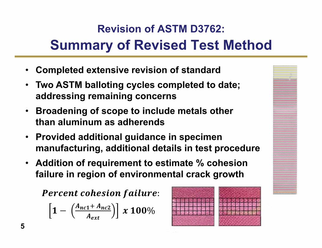
𝑷𝒆𝒓𝒄𝒆𝒏𝒕 𝒄𝒐𝒉𝒆𝒔𝒊𝒐𝒏 𝒇𝒂𝒊𝒍𝒖𝒓𝒆:
𝟏 𝑨𝒏𝒄𝟏 𝑨𝒏𝒄𝟐𝑨𝒆𝒙𝒕
𝒙 𝟏𝟎𝟎%
• Completed extensive revision of standard• Two ASTM balloting cycles completed to date;
addressing remaining concerns• Broadening of scope to include metals other
than aluminum as adherends• Provided additional guidance in specimen
manufacturing, additional details in test procedure• Addition of requirement to estimate % cohesion
failure in region of environmental crack growth
Revision of ASTM D3762:Summary of Revised Test Method
5
Collaborations with ASTM D14 (Adhesives):Formation of D14.80.01 Task Group
• Includes ASTM D14 (Adhesives) and ASTM D30 (Composites) committee members
• Meets concurrently with ASTM D30 to allow for greater participation• Balloting through D14.80 subcommittee and D14 main committee• Technical contact(s) from D30 to attend D14 meetings and provide
TG status reports
Current Activities• ASTM D3762 Metal Wedge Test revision• ASTM D5656 Thick Adherend Lap Shear Test revision• Bonded composite fracture mechanics test evaluation• Composite Wedge Test development/standardization
6

7
Improvements to ASTM D5656–Thick Adherend Lap Shear Test• Best practices for shear strain measurement
– Identify suitable replacement(s) for obsolete KGR‐1 extensometer
– Optimal attachment points for shear strain measurement
• Initial round‐robin investigation completed• Follow‐on round‐robin investigation planned
– AFRL specimens, single film adhesive– Evaluation of candidate shear strain measurement
methods• Update ASTM D5656 Standard• In conjunction with CMH‐17
Current Activities:ASTM D14.80.01 Task Group
Adhesive Test
Section
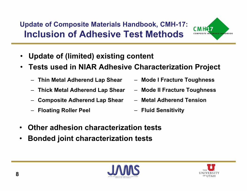
Update of Composite Materials Handbook, CMH-17:Inclusion of Adhesive Test Methods
• Update of (limited) existing content• Tests used in NIAR Adhesive Characterization Project
8
– Thin Metal Adherend Lap Shear
– Thick Metal Adherend Lap Shear
– Composite Adherend Lap Shear
– Floating Roller Peel
– Mode I Fracture Toughness
– Mode II Fracture Toughness
– Metal Adherend Tension
– Fluid Sensitivity
• Other adhesion characterization tests• Bonded joint characterization tests
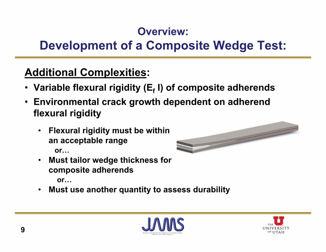
Additional Complexities:• Variable flexural rigidity (Ef I) of composite adherends• Environmental crack growth dependent on adherend
flexural rigidity• Flexural rigidity must be within
an acceptable range or…
• Must tailor wedge thickness for composite adherends
or…• Must use another quantity to assess durability
Overview:Development of a Composite Wedge Test:
9
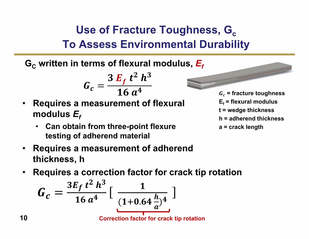
GC written in terms of flexural modulus, Ef
𝒄𝒇
𝟐 𝟑
𝟒 𝑮𝒄 = fracture toughnessEf = flexural modulust = wedge thicknessh = adherend thicknessa = crack length
• Requires a measurement of flexural modulus Ef • Can obtain from three-point flexure
testing of adherend material• Requires a measurement of adherend
thickness, h• Requires a correction factor for crack tip rotation
𝒄𝟑𝑬𝒇 𝒕𝟐 𝒉𝟑
𝟏𝟔 𝒂𝟒𝟏
𝟏 𝟎.𝟔𝟒 𝒉𝒂𝟒
Correction factor for crack tip rotation10
Use of Fracture Toughness, GcTo Assess Environmental Durability
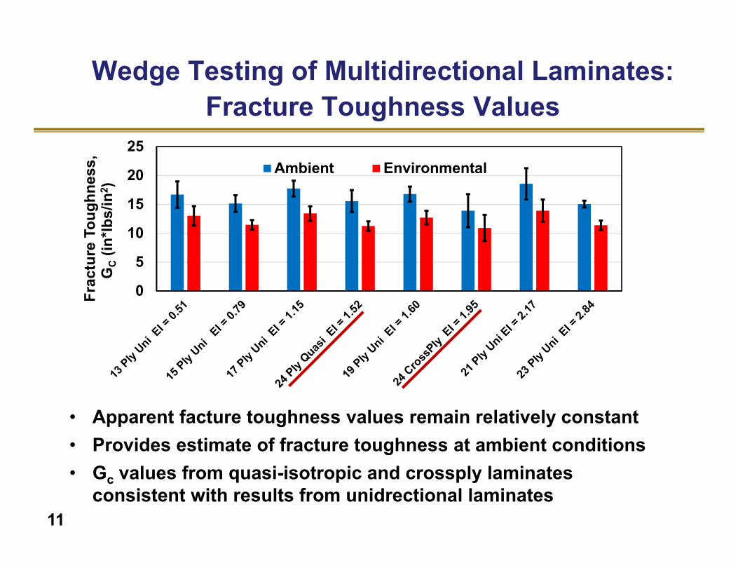
Wedge Testing of Multidirectional Laminates:Fracture Toughness Values
0
5
10
15
20
25
Frac
ture
Tou
ghne
ss,
GC
(in*lb
s/in
2 )
Ambient Environmental
• Apparent facture toughness values remain relatively constant• Provides estimate of fracture toughness at ambient conditions• Gc values from quasi-isotropic and crossply laminates
consistent with results from unidrectional laminates11
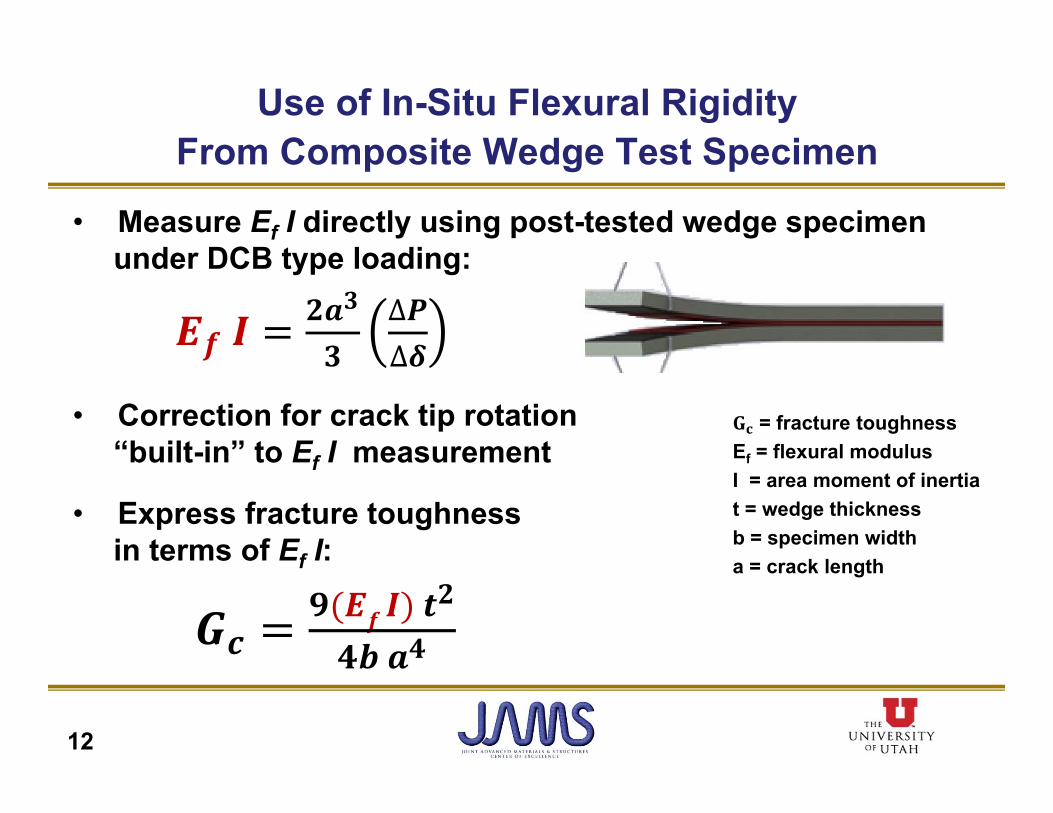
• Measure Ef I directly using post-tested wedge specimen under DCB type loading:
𝒇𝟐𝒂𝟑
𝟑∆𝑷∆𝜹
• Correction for crack tip rotation “built-in” to Ef I measurement
• Express fracture toughness in terms of Ef I:
𝒇 𝟐
𝟒
Use of In-Situ Flexural Rigidity From Composite Wedge Test Specimen
𝐆𝐜 = fracture toughnessEf = flexural modulusI = area moment of inertiat = wedge thicknessb = specimen widtha = crack length
12
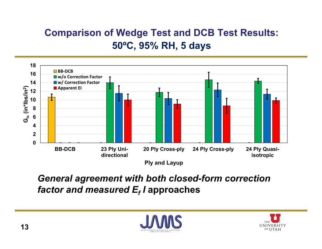
Comparison of Wedge Test and DCB Test Results:50ºC, 95% RH, 5 days
General agreement with both closed-form correction factor and measured Ef I approaches
13
02468
1012141618
BB-DCB 23 Ply Uni-directional
20 Ply Cross-ply 24 Ply Cross-ply 24 Ply Quasi-isotropic
GIc
(in*lb
s/in
2 )
Ply and Layup
BB‐DCBw/o Correction Factorw/ Correction FactorApparent EI

• ABAQUS 3D finite element analysis • Crack modeled at center of adhesive bondline (cohesion failure)
• Highly refined mesh in vicinity of crack tip• Displacement loading to simulate wedge inserted in bondline
• Investigation of candidate methods for Gc calculation using results from simulated composite wedge test
• Use of VCCT to calculate reference Gc value
14
Evaluation of Gc Calculation Methods:Numerical Simulations
0.0
0.5
1.0
1.5
2.0
2.5
3.0
3.5
Ef = E11 Ef = E11 3 PointBend Ef
DCB derivedEf
VCCT
GIc
(in*
lbs/
in2 )
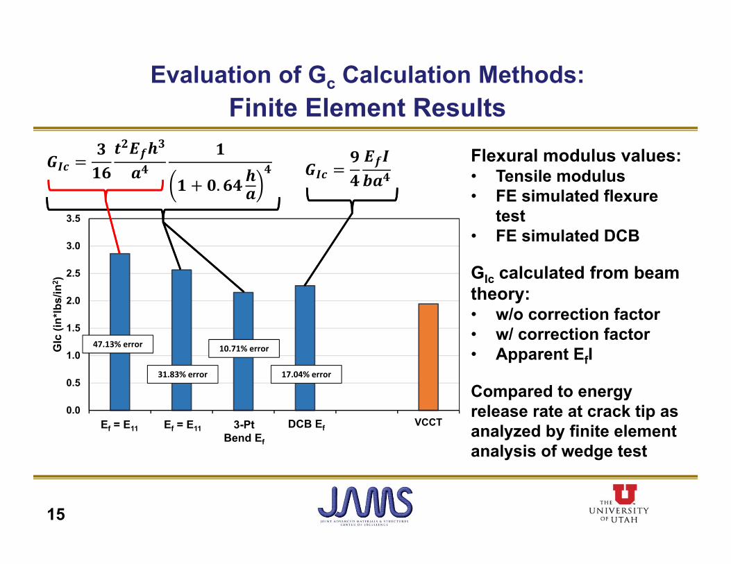
Flexural modulus values:• Tensile modulus• FE simulated flexure
test• FE simulated DCB
GIc calculated from beam theory:• w/o correction factor• w/ correction factor• Apparent EfI
Compared to energy release rate at crack tip as analyzed by finite element analysis of wedge test
15
Ef = E11 3-Pt Bend Ef
DCB Ef
47.13% error
31.83% error
10.71% error
17.04% error
Ef = E11
𝑮𝑰𝒄𝟑
𝟏𝟔𝒕𝟐𝑬𝒇𝒉𝟑
𝒂𝟒𝟏
𝟏 𝟎. 𝟔𝟒 𝒉𝒂
𝟒 𝑮𝑰𝒄𝟗𝟒
𝑬𝒇𝑰𝒃𝒂𝟒
Evaluation of Gc Calculation Methods:Finite Element Results
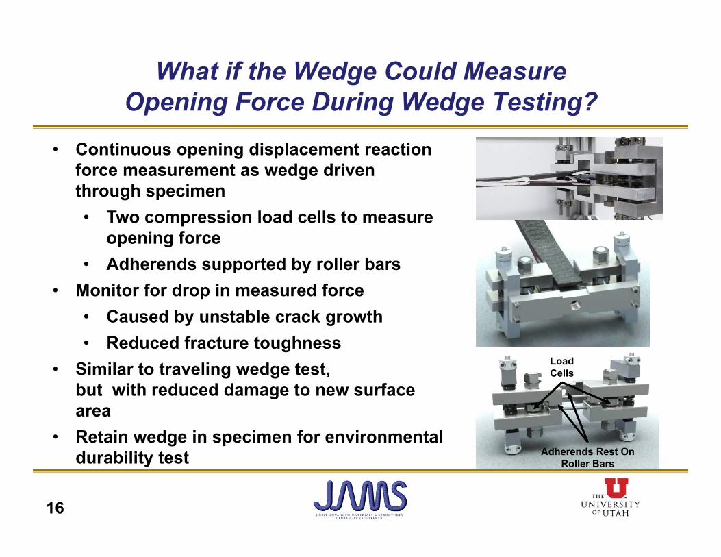
What if the Wedge Could Measure Opening Force During Wedge Testing?
• Continuous opening displacement reaction force measurement as wedge driven through specimen• Two compression load cells to measure
opening force• Adherends supported by roller bars
• Monitor for drop in measured force• Caused by unstable crack growth• Reduced fracture toughness
• Similar to traveling wedge test, but with reduced damage to new surface area
• Retain wedge in specimen for environmental durability test
Load Cells
Adherends Rest On Roller Bars
16

Smart Wedge Testing:Operation & Procedure
17
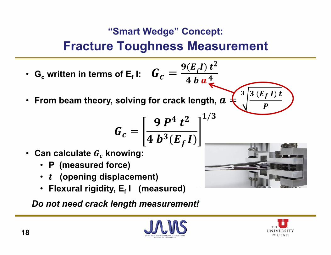
• Gc written in terms of Ef I: 𝒄𝟗 𝑬𝒇𝑰 𝒕𝟐
𝟒 𝒃 𝒂 𝟒
• From beam theory, solving for crack length, 𝟑 𝑬𝒇 𝑰 𝒕
𝑷
𝟑
𝒄
𝟒 𝟐
𝟑𝒇
𝟏/𝟑
• Can calculate 𝑮𝒄 knowing:• P (measured force)• 𝒕 (opening displacement) • Flexural rigidity, Ef I (measured)
Do not need crack length measurement!
“Smart Wedge” Concept: Fracture Toughness Measurement
18
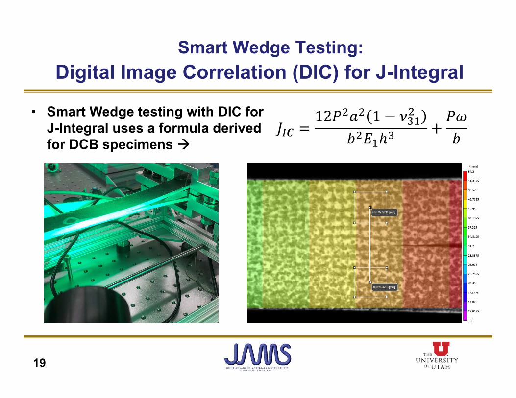
Smart Wedge Testing:Digital Image Correlation (DIC) for J-Integral
19
• Smart Wedge testing with DIC for J-Integral uses a formula derived for DCB specimens
𝐽 𝑪12𝑃 𝑎 1 𝜈
𝑏 𝐸 ℎ𝑃𝜔𝑏
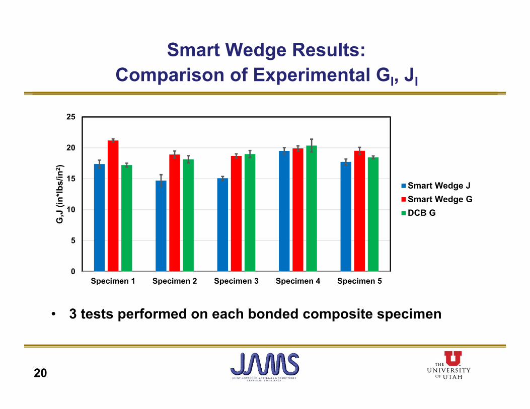
Smart Wedge Results:Comparison of Experimental GI, JI
20
• 3 tests performed on each bonded composite specimen
0
5
10
15
20
25
Specimen 1 Specimen 2 Specimen 3 Specimen 4 Specimen 5
G,J
(in*
lbs/
in2 )
Smart Wedge JSmart Wedge GDCB G
21
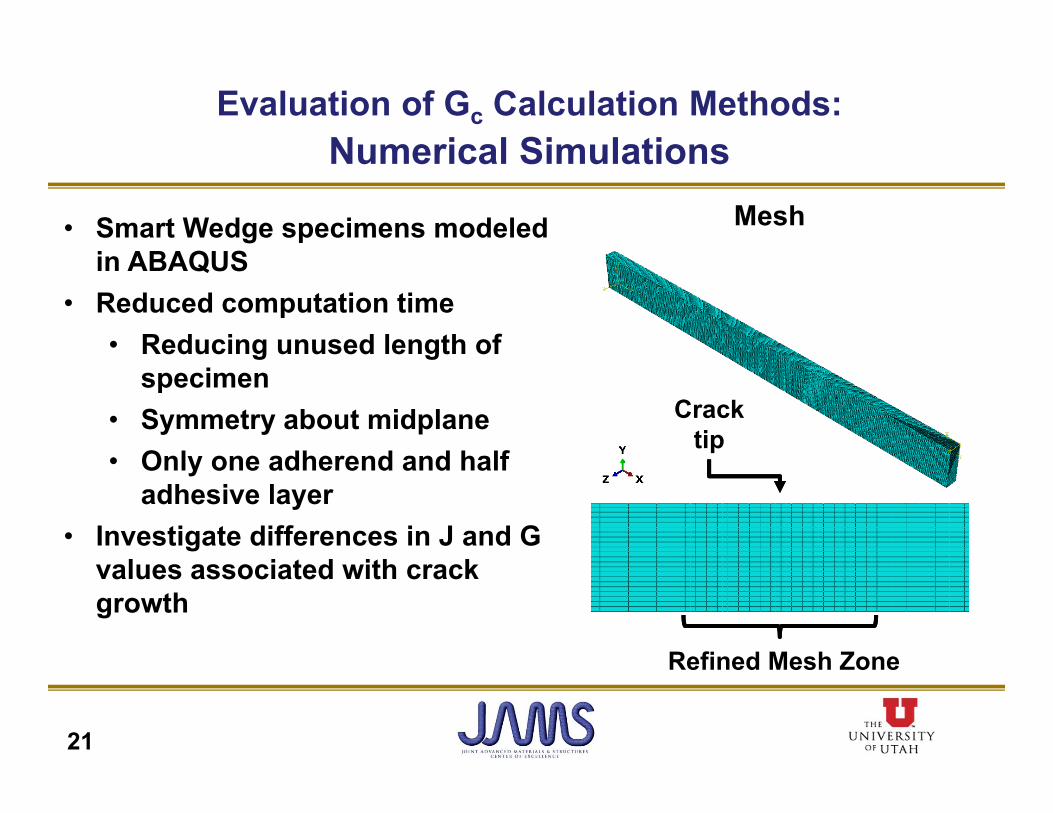
• Smart Wedge specimens modeled in ABAQUS
• Reduced computation time• Reducing unused length of
specimen• Symmetry about midplane• Only one adherend and half
adhesive layer• Investigate differences in J and G
values associated with crackgrowth
Mesh
Crack tip
Refined Mesh Zone
Evaluation of Gc Calculation Methods:Numerical Simulations
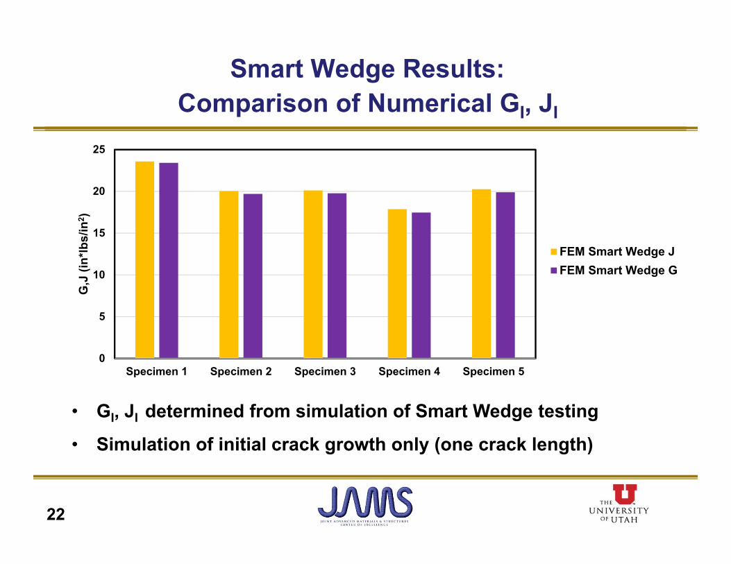
Smart Wedge Results:Comparison of Numerical GI, JI
22
• GI, JI determined from simulation of Smart Wedge testing
• Simulation of initial crack growth only (one crack length)
0
5
10
15
20
25
Specimen 1 Specimen 2 Specimen 3 Specimen 4 Specimen 5
G,J
(in*
lbs/
in2 )
FEM Smart Wedge JFEM Smart Wedge G
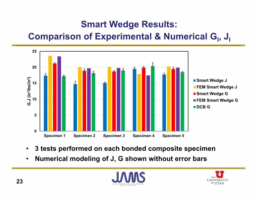
Smart Wedge Results:Comparison of Experimental & Numerical GI, JI
23
• 3 tests performed on each bonded composite specimen• Numerical modeling of J, G shown without error bars
0
5
10
15
20
25
Specimen 1 Specimen 2 Specimen 3 Specimen 4 Specimen 5
G,J
(in*
lbs/
in2 ) Smart Wedge J
FEM Smart Wedge JSmart Wedge GFEM Smart Wedge GDCB G
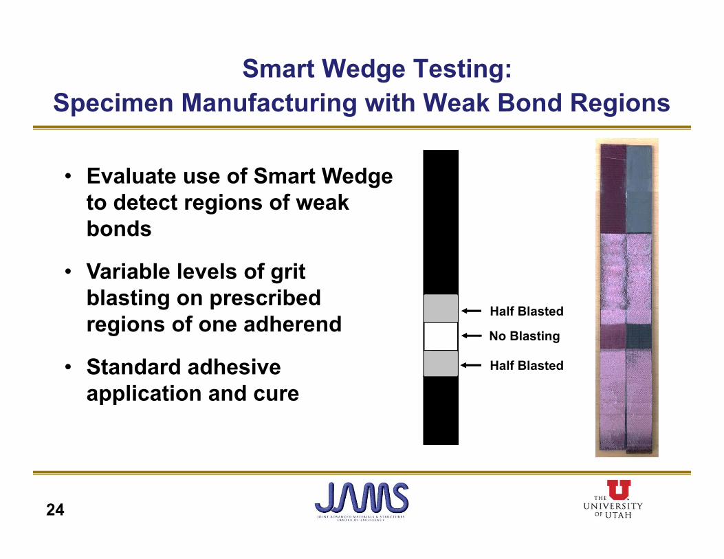
Smart Wedge Testing:Specimen Manufacturing with Weak Bond Regions
24
• Evaluate use of Smart Wedge to detect regions of weak bonds
• Variable levels of gritblasting on prescribed regions of one adherend
• Standard adhesive application and cure
Half Blasted
Half Blasted
No Blasting
25
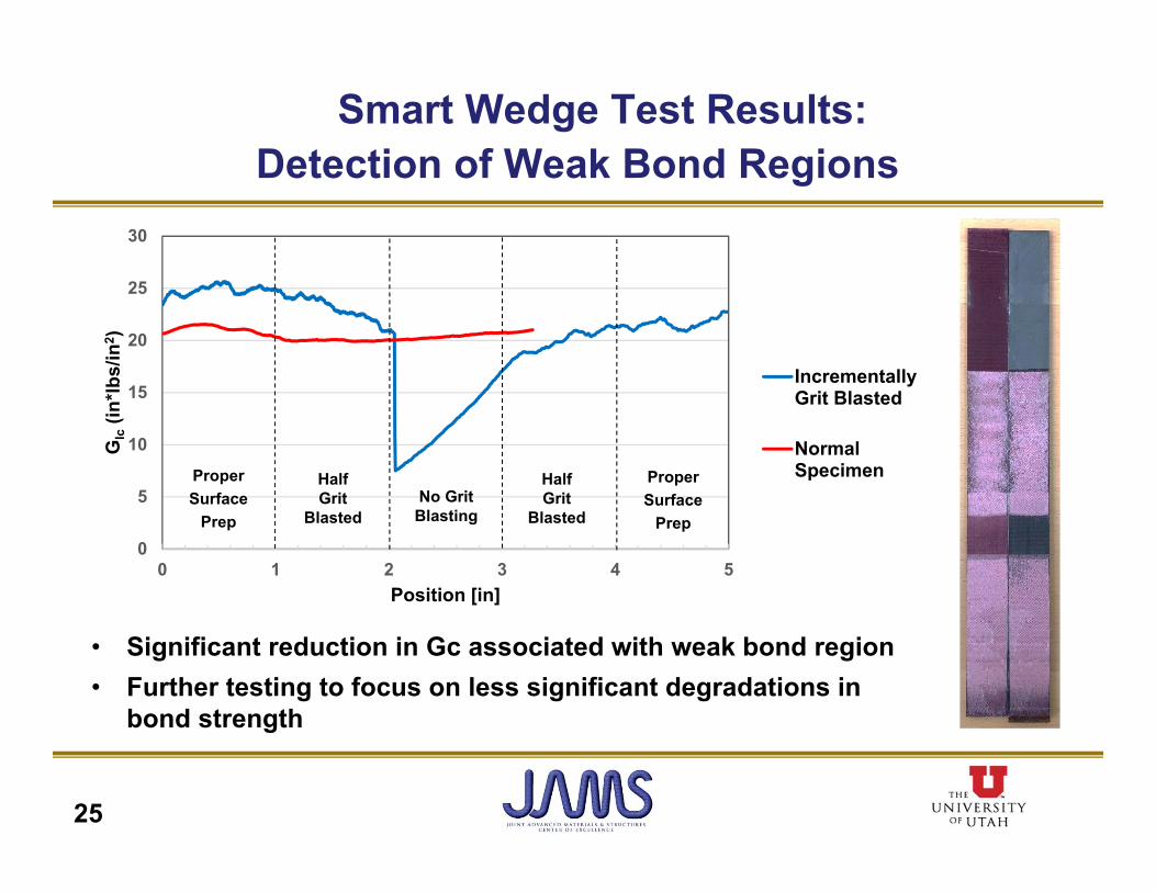
• Significant reduction in Gc associated with weak bond region• Further testing to focus on less significant degradations in
bond strength
0
5
10
15
20
25
30
0 1 2 3 4 5
GIc
(in*lb
s/in
2 )
Position [in]
IncrementallyGrit Blasted
NormalSpecimenHalf
GritBlasted
Half Grit
BlastedNo Grit
Blasting
ProperSurface
Prep
ProperSurface
Prep
Smart Wedge Test Results:Detection of Weak Bond Regions

BENEFITS TO AVIATION• Improved environmental durability test method for metal
bonds (metal wedge test, ASTM D3762)
• Improved shear test method for adhesives (ASTM D5656)
• Composite wedge test for assessing the environmental durability of composite bonds and assessing surface preparations
• Hybrid traveling wedge/static wedge test for evaluation of larger bond areas
• Dissemination of research results through FAA technical reports and conference/journal publications
26

Questions?
Don’t forget to fill out the feedback form in your packet or online at
www.surveymonkey.com/r/jamsfeedback
Thank you.
27