Embed Size (px)
Citation preview
Environmental Degradation of Micro- & Nano-Composites
Dr. Muhammad ShahidDept of Mechanical Engineering,
College of EME, NUST
www.ceme.edu.pk
• CorrosionDeterioration of materials (generally metals or alloys) resulting from electrochemical attack by its environment (usually aqueous). It is usually a low temperature phenomenon.
• DegradationNon-metallic materials such as ceramics & polymers do not suffer electrochemical attack but can be deteriorated by direct chemical attack.
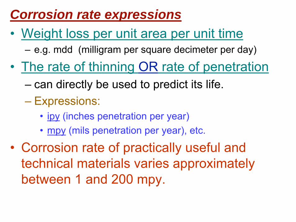
Corrosion rate expressions• Weight loss per unit area per unit time
– e.g. mdd (milligram per square decimeter per day)
• The rate of thinning OR rate of penetration– can directly be used to predict its life. – Expressions:
• ipy (inches penetration per year) • mpy (mils penetration per year), etc.
• Corrosion rate of practically useful and technical materials varies approximately between 1 and 200 mpy.
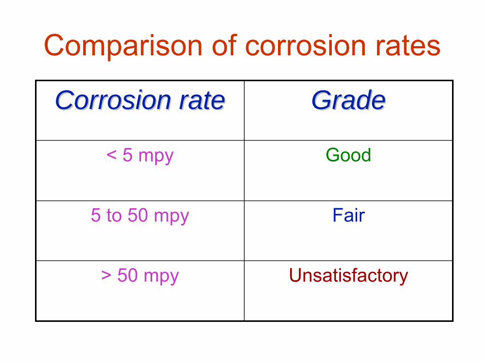
Comparison of corrosion rates
Corrosion rateCorrosion rate GradeGrade
< 5 mpy Good
5 to 50 mpy Fair
> 50 mpy Unsatisfactory
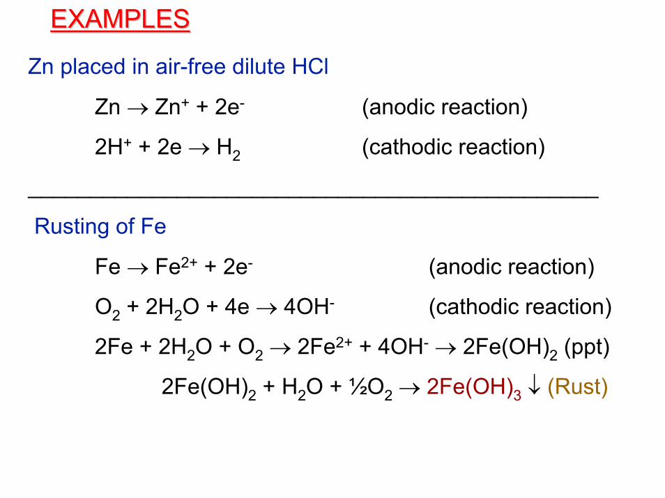
Zn placed in air-free dilute HCl
Zn → Zn+ + 2e- (anodic reaction)
2H+ + 2e → H2 (cathodic reaction)
______________________________________________
Rusting of Fe
Fe → Fe2+ + 2e- (anodic reaction)
O2 + 2H2O + 4e → 4OH- (cathodic reaction)
2Fe + 2H2O + O2 → 2Fe2+ + 4OH- → 2Fe(OH)2 (ppt)
2Fe(OH)2 + H2O + ½O2 → 2Fe(OH)3 ↓ (Rust)
EXAMPLESEXAMPLES
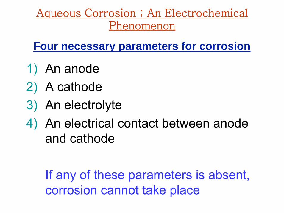
Aqueous Corrosion ; An Electrochemical Phenomenon
1) An anode2) A cathode3) An electrolyte4) An electrical contact between anode
and cathode
If any of these parameters is absent, corrosion cannot take place
Four necessary parameters for corrosion
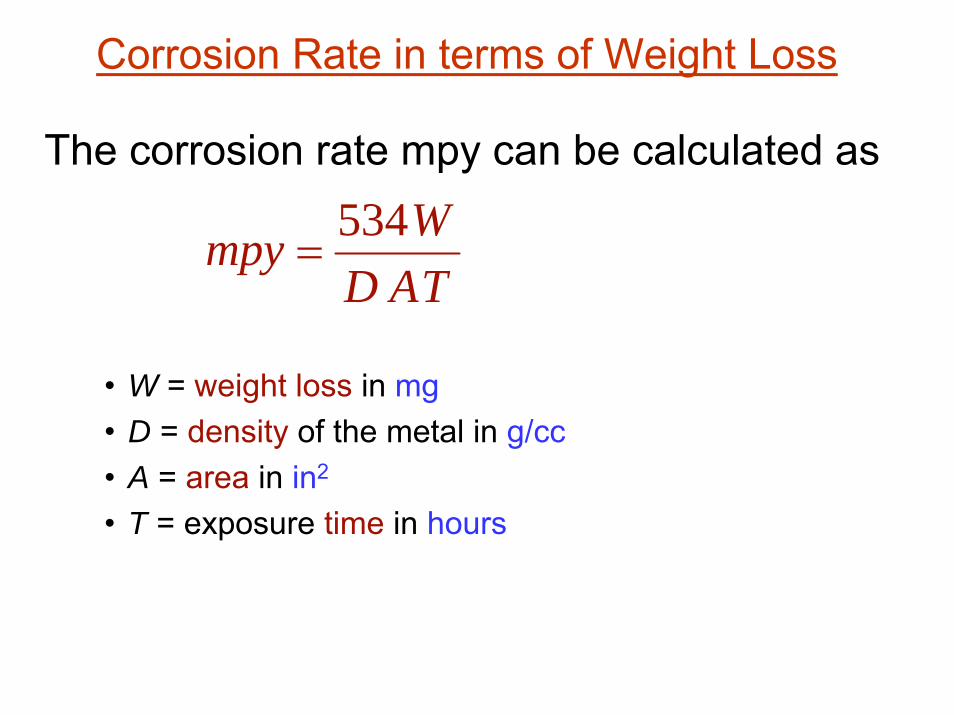
The corrosion rate mpy can be calculated as
• W = weight loss in mg• D = density of the metal in g/cc• A = area in in2
• T = exposure time in hours
Corrosion Rate in terms of Weight Loss
TADWmpy 534
=
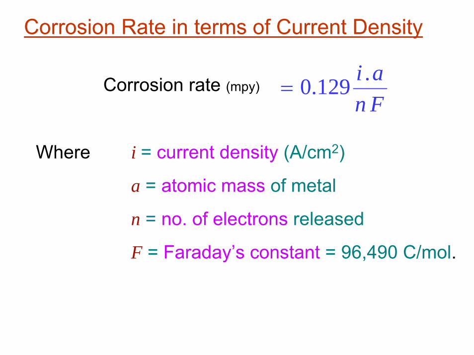
Corrosion Rate in terms of Current Density
Corrosion rate (mpy)Fnai .129.0=
Where i = current density (A/cm2)
a = atomic mass of metal
n = no. of electrons released
F = Faraday’s constant = 96,490 C/mol.
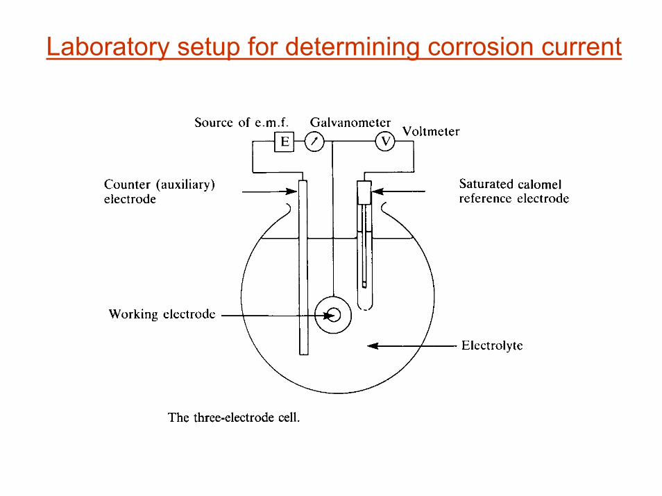
Laboratory setup for determining corrosion current


Galvanic cells are generated by differences in Composition, Structure, and Stress.1. Grain vs. grain-boundary galvanic cells
2. Multiple-phase galvanic cells
3. Impurity galvanic cells
Sources of Galvanic Cells
A composite has similar features:An interface between matrix and reinforcement
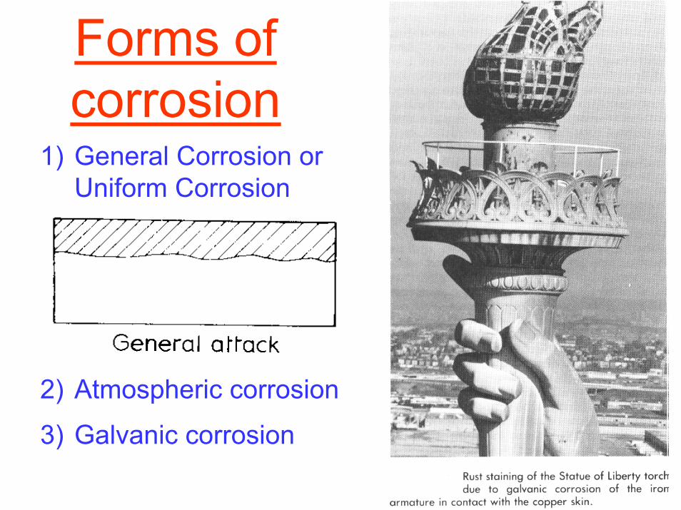
Forms of corrosion
2) Atmospheric corrosion
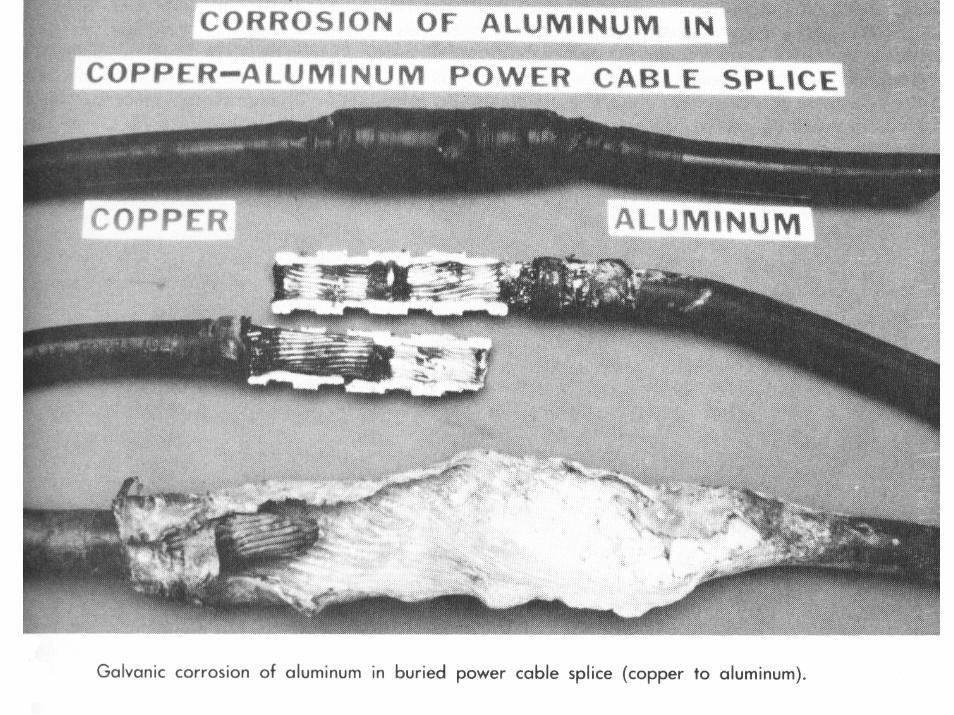
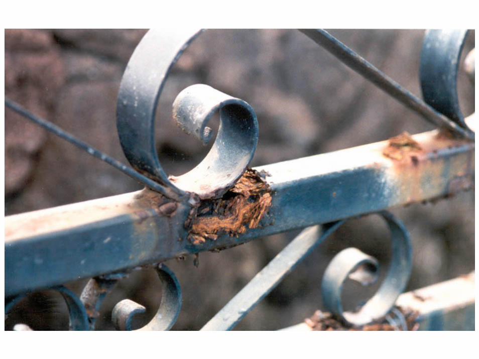
3) Galvanic corrosion
1) General Corrosion or Uniform Corrosion


4) Crevice corrosion
Localized Corrosion
5) Pitting


6) Intergranular corrosion
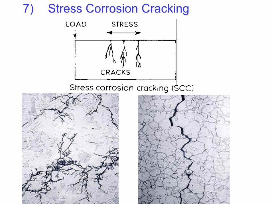
7) Stress Corrosion Cracking
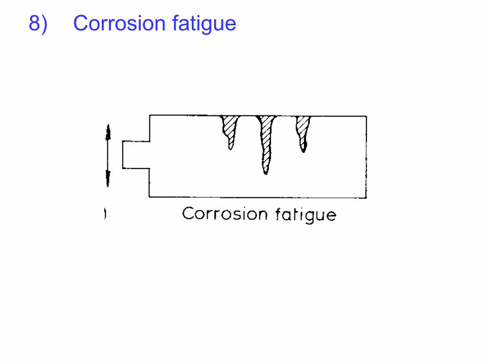
8) Corrosion fatigue
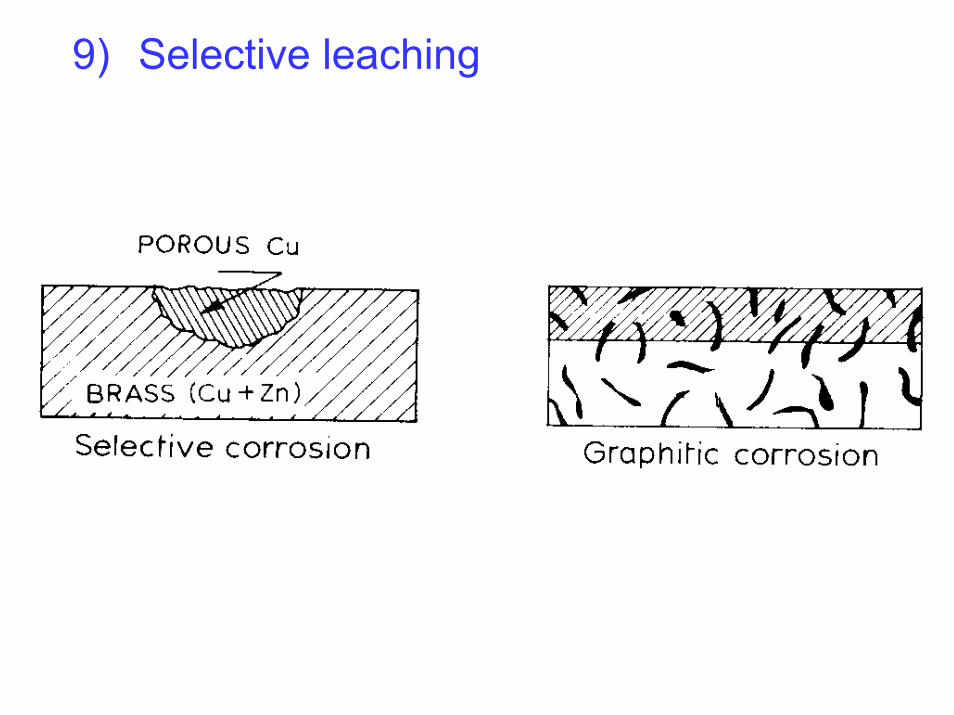
9) Selective leaching
10) Microbiological corrosion
11) Erosion corrosion
12) Stray current corrosion
13) Cavitation & Impingement
14) High temperature corrosion
• High temperature oxidation
• Hot corrosion
• Hot ash corrosion
Factors accelerating corrosion
• Humidity• Temperature• pH• Aggressive ions• Oxygen• Thermal & Mech. Stresses• Velocity of fluid• Pressure

CORROSION CONTROL CORROSION CONTROL TECHNIQUESTECHNIQUES

• Avoid bimetallic coupling– Use galvanic series for the particular electrolyte
• Avoid crevices• Avoid sharp bends and corners• Avoid deposit on the surface• Stress relieving• Optimum fluid velocity• Avoid Stray Current
Control by DesignControl by Design

Control byControl byEnvironmental ChangeEnvironmental Change
• Control water chemistry• Use Inhibitors
– Anodic inhibitors– Cathodic inhibitors– Mixed Inhibitors
• Oxygen removal– Oxygen scavengers should be used with care
• E.g. Hydrazine (liberates Ammonia on dissociation)—corrosive to copper and Cu-alloys
Control by CoatingsControl by Coatings• Epoxies • Polyurethanes• Vinyls• Plastics• Nylon• Rubber• Metals• PTFE (Teflon)
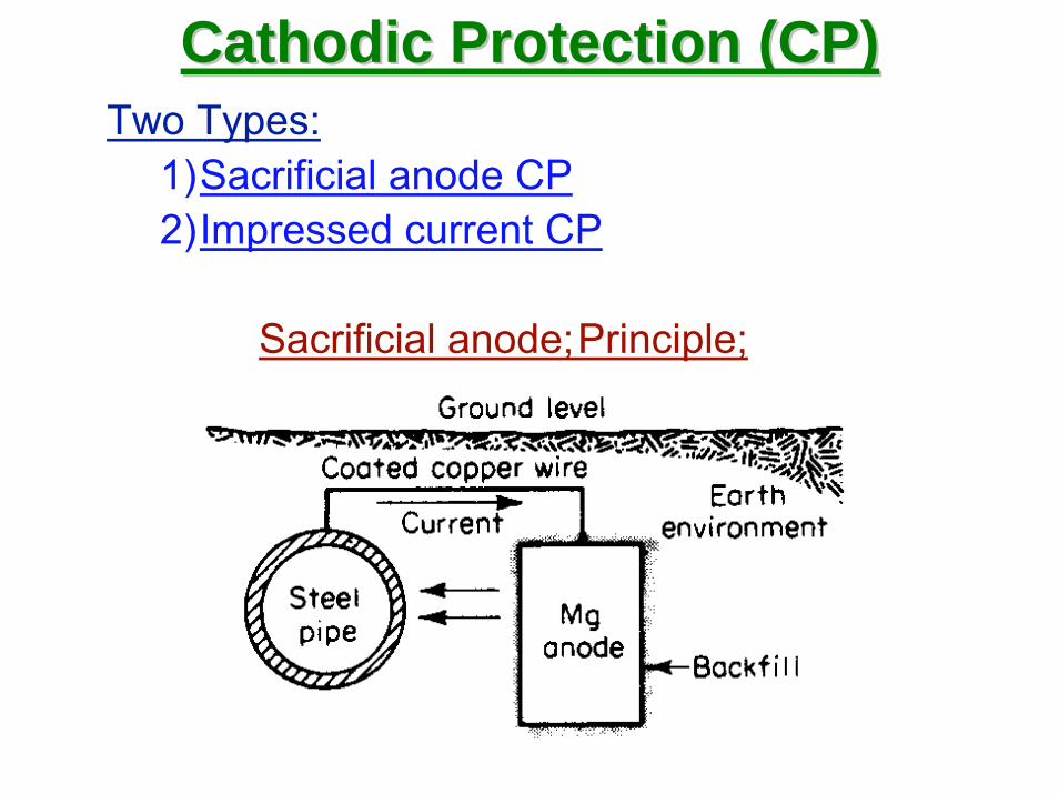
Cathodic Protection (CP)Cathodic Protection (CP)Two Types:
1)Sacrificial anode CP2)Impressed current CP
Sacrificial anode;Principle;

Cathodic Protection (CP)Cathodic Protection (CP)
CP of a domestic water geyser using a sacrificial anode

Cathodic Protection (CP)Cathodic Protection (CP)
Impressed current; Principle
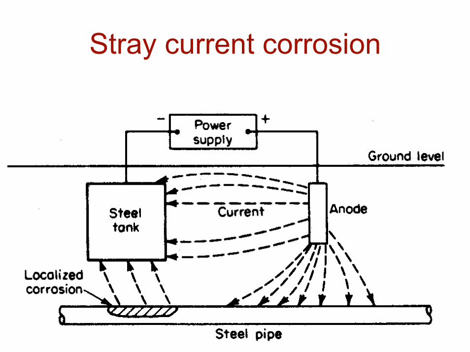
Stray current corrosion
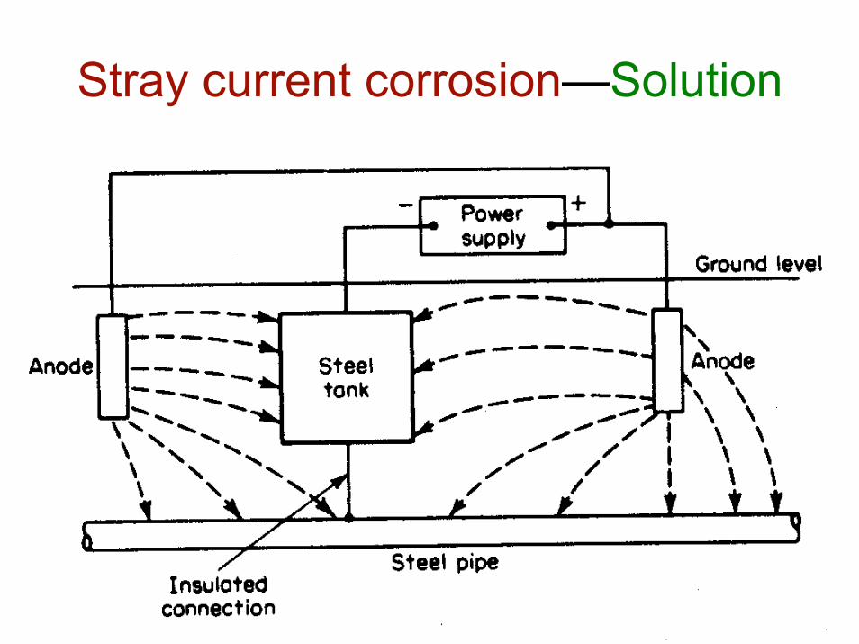
Stray current corrosion—Solution

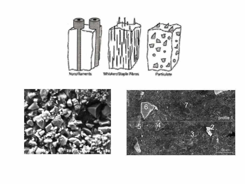
Corrosion in MMCs• Metal Matrix Composites
– Sources for cell generation:• Interface between matrix and reinforcement• The interface acts as anodic site and the
reinforcement serves as cathode.• Anodes dissolves; the reinforcement loses strength
and falls out• Corrosion propagates inside through the interface.

Most important MMC systems:• Aluminum matrix
– Continuous fibers: boron, silicon carbide, alumina, graphite – Discontinuous fibers: alumina, alumina-silica – Whiskers: silicon carbide – Particulates: silicon carbide, boron carbide
• Magnesium matrix – Continuous fibers: graphite, alumina – Whiskers: silicon carbide – Particulates: silicon carbide, boron carbide
• Titanium matrix – Continuous fibers: silicon carbide, coated boron – Particulates: titanium carbide
• Copper matrix – Continuous fibers: graphite, silicon carbide – Wires: niobium-titanium, niobium-tin – Particulates: silicon carbide, boron carbide, titanium carbide.
• Superalloy matrices – Wires: tungsten
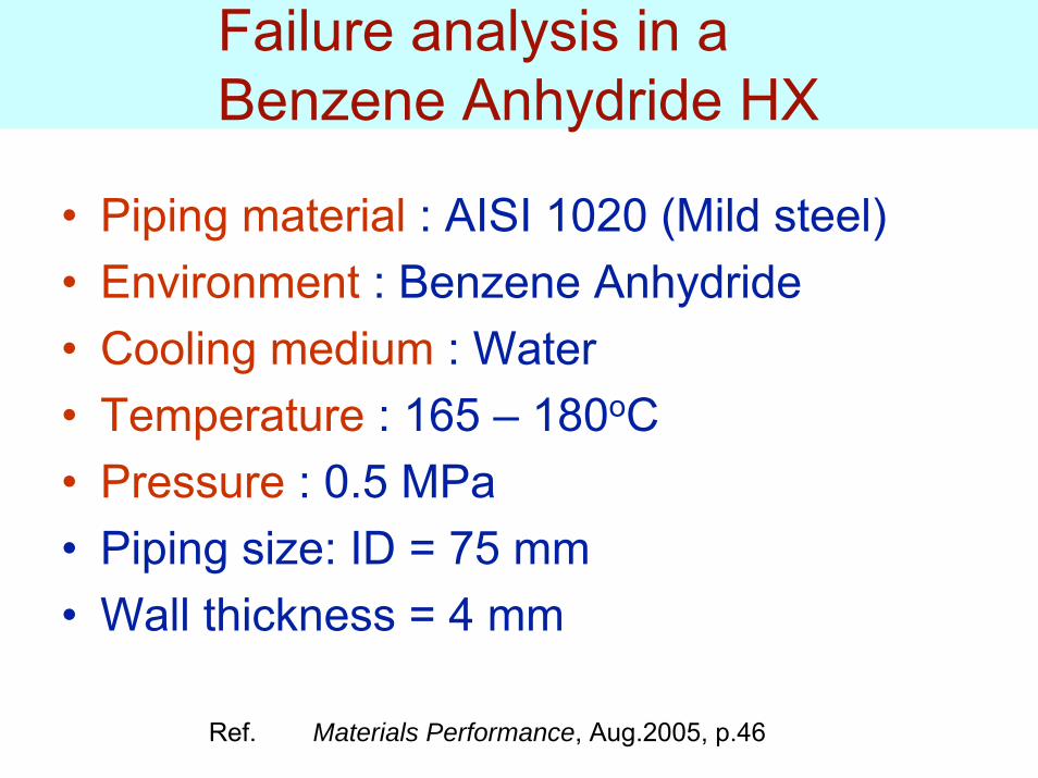
Failure analysis in a Benzene Anhydride HX
• Piping material : AISI 1020 (Mild steel)• Environment : Benzene Anhydride• Cooling medium : Water• Temperature : 165 – 180oC• Pressure : 0.5 MPa• Piping size: ID = 75 mm• Wall thickness = 4 mm
Ref. Materials Performance, Aug.2005, p.46

• Corrosion type– Grain boundary corrosion– Pitting
• Both lead to Stress Corrosion Cracking• Source of corrosion
– S & Cl was found at g.b.• Suggestions for remedy:
– Material replacement • SS 316 or SS316L
– Impurities of Cl & S to be reduced.
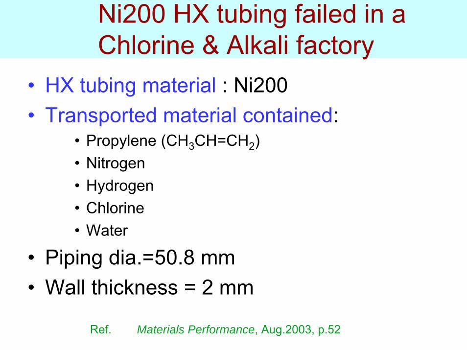
Ni200 HX tubing failed in a Chlorine & Alkali factory
• HX tubing material : Ni200• Transported material contained:
• Propylene (CH3CH=CH2)• Nitrogen• Hydrogen• Chlorine• Water
• Piping dia.=50.8 mm• Wall thickness = 2 mm
Ref. Materials Performance, Aug.2003, p.52
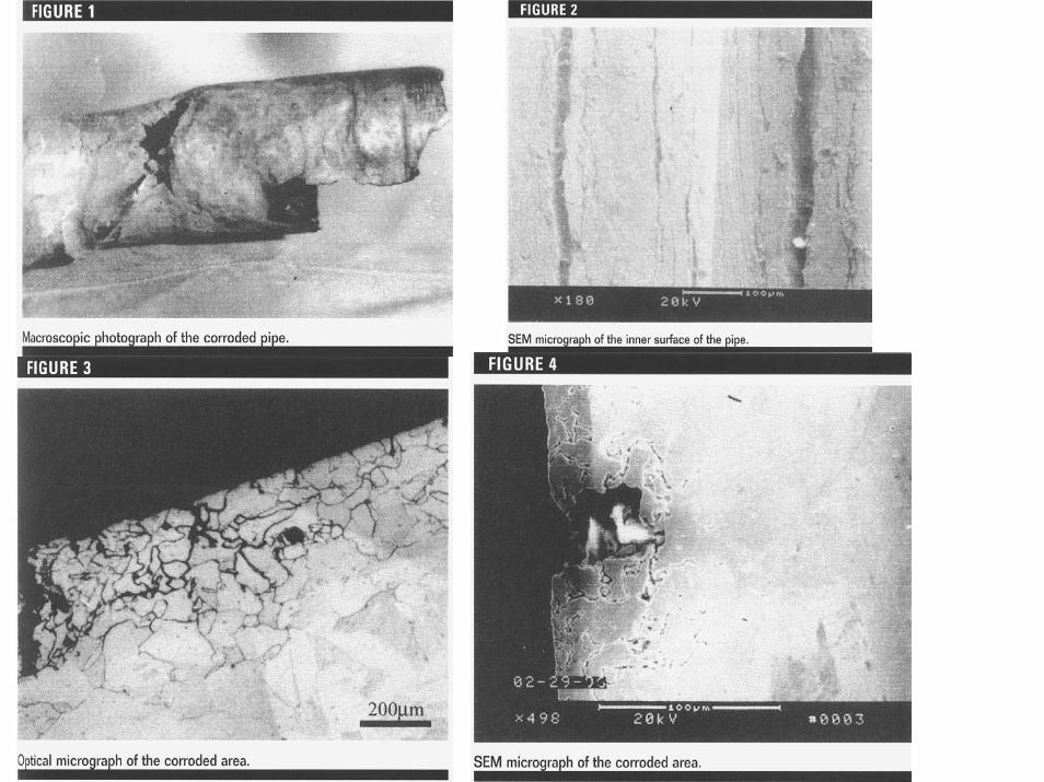

Failure mode
• Intergranular corrosion• Caused decrease in thickness• Later on Plastic deformation occurred• Leading to SCC

Degradation of Glasses, Ceramics & CMCs
• These materials are:– Oxides, fluorides, borates, phosphates, etc.
• Ceramics—crystalline: • Glasses—non-crystalline or amorphous
– Electrically insulating and contain few carriers, hence,• Chemical attack mainly by acid-base type of reactions rather
than electrochemical redox reactions.• Glasses & ceramics of similar composition—often have quite
different corrosion behavior—structure at atomic scale plays an important role.
– Literature on corrosion of ceramics is sparse since these are not affected under normal aqueous environment.
Glasses, Ceramics & CMCs
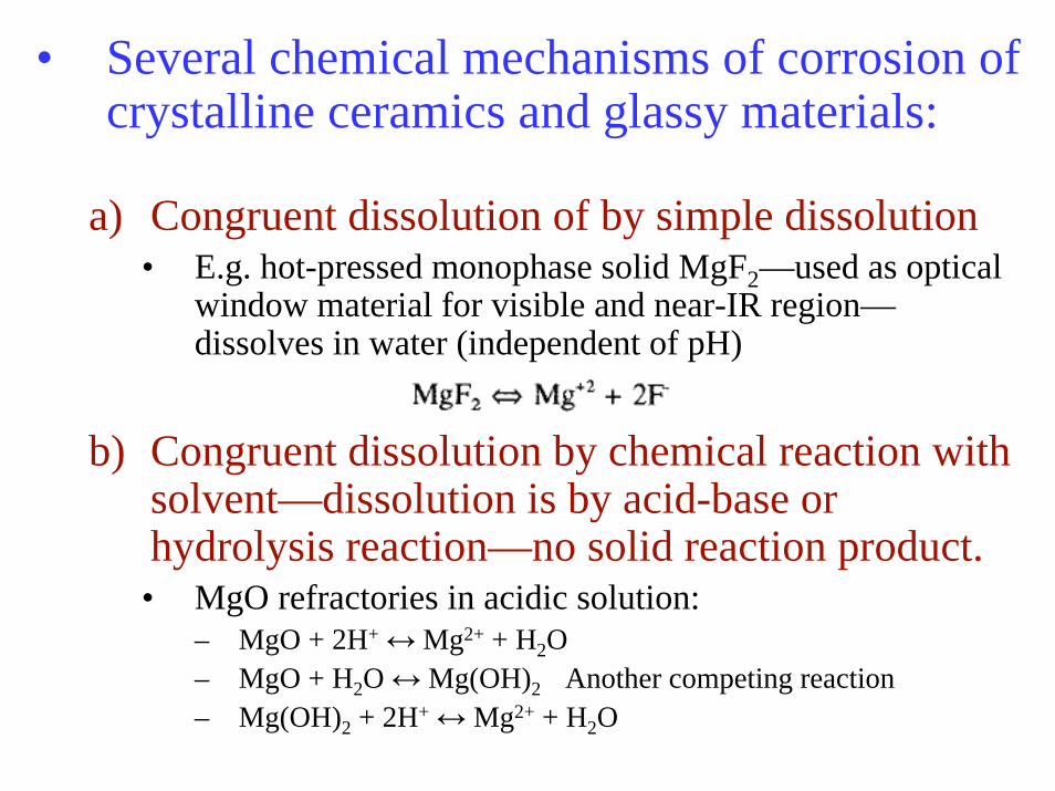
• Several chemical mechanisms of corrosion of crystalline ceramics and glassy materials:
a) Congruent dissolution of by simple dissolution• E.g. hot-pressed monophase solid MgF2—used as optical
window material for visible and near-IR region—dissolves in water (independent of pH)
b) Congruent dissolution by chemical reaction with solvent—dissolution is by acid-base or hydrolysis reaction—no solid reaction product.
• MgO refractories in acidic solution:– MgO + 2H+ ↔ Mg2+ + H2O– MgO + H2O ↔ Mg(OH)2 Another competing reaction– Mg(OH)2 + 2H+ ↔ Mg2+ + H2O

c) Incongruent dissolution with formation of crystalline reaction product.
SrTiO3 + 2H+ ↔ Sr2+ + TiO2
d) Incongruent dissolution with formation of non-crystalline reaction layers.
e) Ion-Exchange
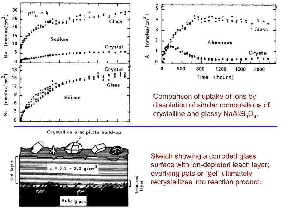
Comparison of uptake of ions by dissolution of similar compositions of crystalline and glassy NaAlSi3O8.
Sketch showing a corroded glass surface with ion-depleted leach layer; overlying ppts or “gel” ultimately recrystallizes into reaction product.


LENS
FUNGUS
PLASTER
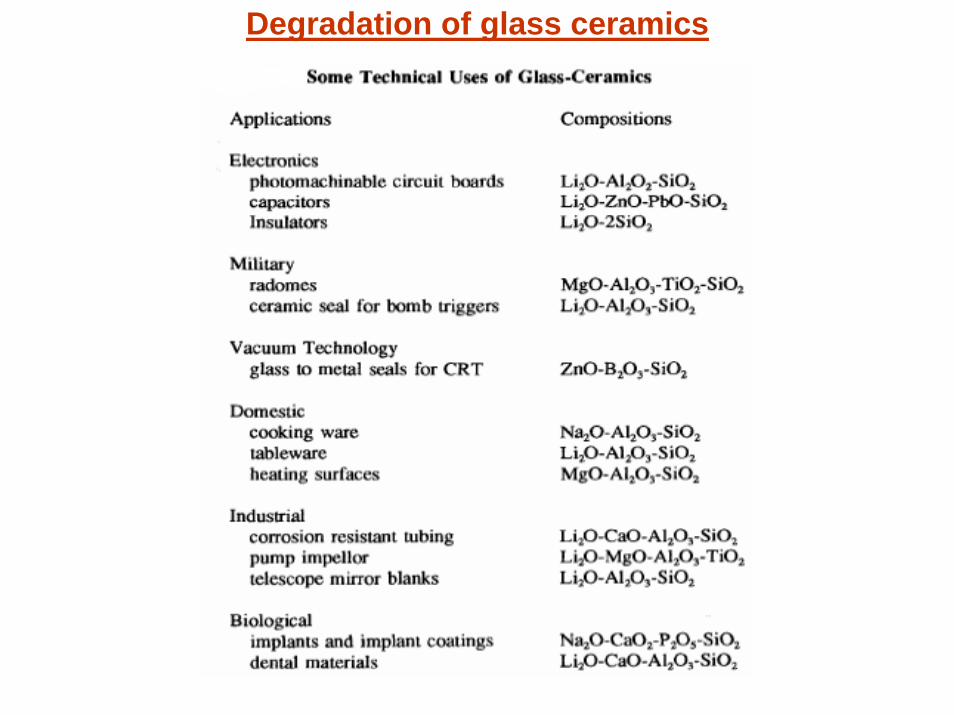
Degradation of glass ceramics
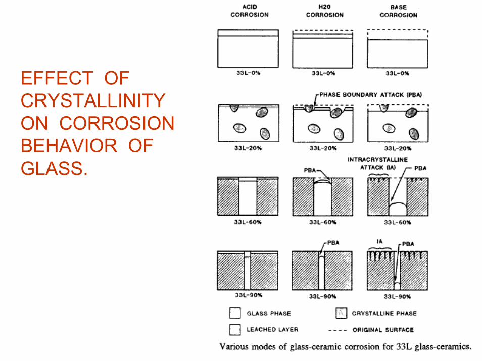
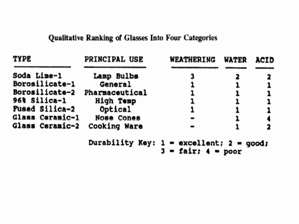
EFFECT OF CRYSTALLINITY ON CORROSION BEHAVIOR OF GLASS.
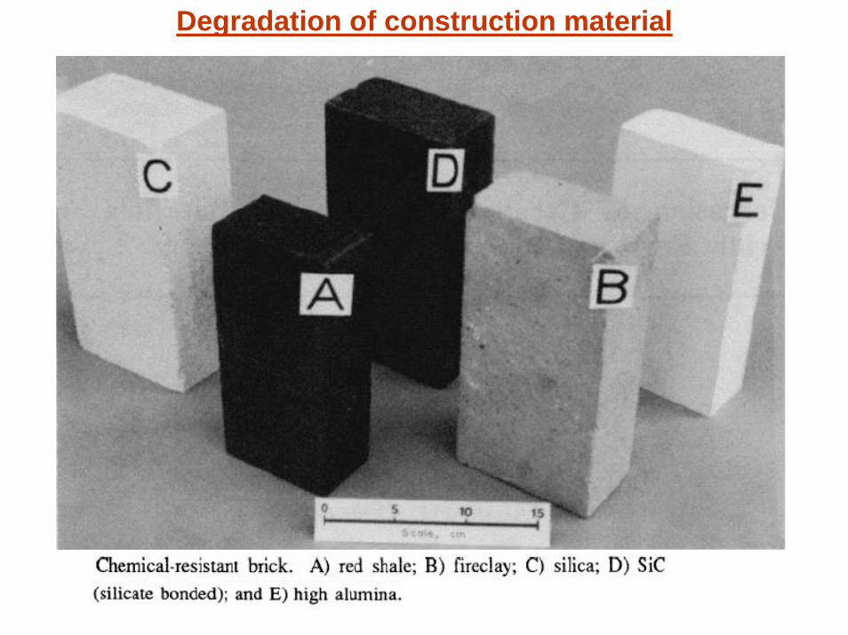
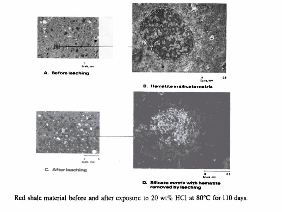
Degradation of construction material
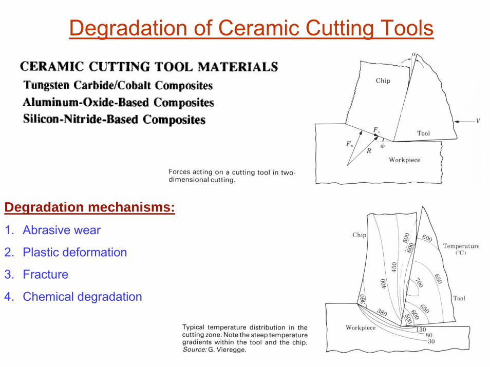
Degradation mechanisms:1. Abrasive wear
2. Plastic deformation
3. Fracture
4. Chemical degradation
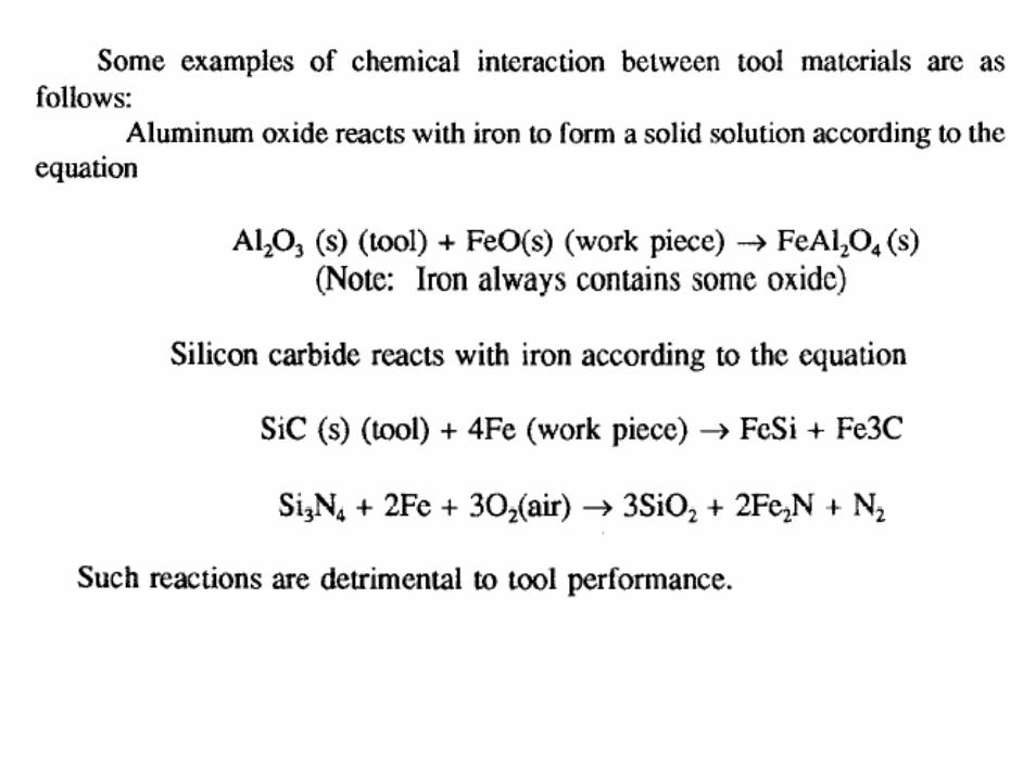
Degradation of Ceramic Cutting Tools
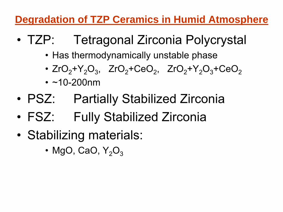
• TZP: Tetragonal Zirconia Polycrystal• Has thermodynamically unstable phase• ZrO2+Y2O3, ZrO2+CeO2, ZrO2+Y2O3+CeO2
• ~10-200nm
• PSZ: Partially Stabilized Zirconia• FSZ: Fully Stabilized Zirconia• Stabilizing materials:
• MgO, CaO, Y2O3
Degradation of TZP Ceramics in Humid Atmosphere
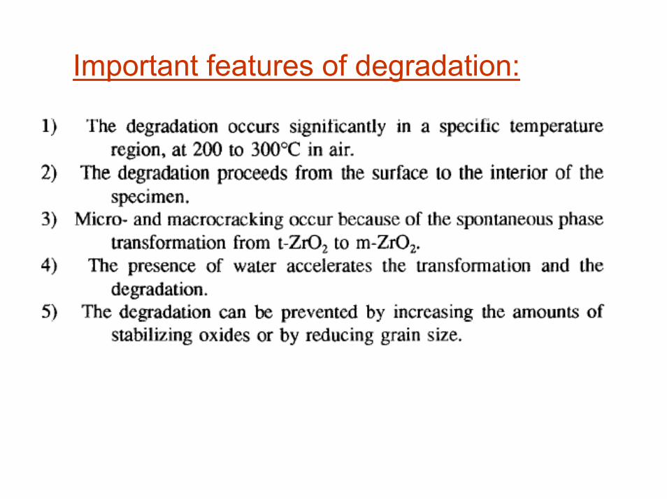
Important features of degradation:
Degradation of Polymer Matrix Nano-composites
Polymer Matrix Nano-Composites• Thermal stability
– In general, nanocomposites of all polymers showed higher thermal stability with dispersion of clay under inert as well as oxygen atmosphere.
• Biodegradability– There is no confirmation about the mechanisms
of bioconsumption in the presence of clay. • UV light
– The degradability under UV light is a serious problem, which may limit the applicability of these materials.

• PE & PP / Clay nanocomposites– Nano composites of these polymers exhibited less
stability than neat polymers. – One may get highly improved material properties by
filling the polymer matrix with layered silicates, but the durability in outdoor application is still a challenge.
– The best way would be to develop nanocomposites by modification in clay rather than functionalisation of thermoplastics to increase the outdoor durability.
• PLA (Polylactide) nanocomposite– In preparation of PLA composites thermal degradation
has been observed even in the presence of thermal stabilizers which lead the deterioration of properties in the resulting products.
• Polyurethane nanocomposite– Durability of few industrially useful polymeric
nanocomposites like polyurethane has not been evaluated in any environment.
• Biodegradable nanocomposites– Nanocomposites especially biodegradable
nanocomposites are an emerging new class of materials.
– These nanocomposites are the wave of the future and considered as the material of next generation.
– The moisture sensitivity is still a problem in the starch nanocomposites.
• Overall there is essential requirement to investigate the durability of these nanocomposites in different environmental conditions to extend the applicability of these hybrid materials.