Embed Size (px)
Citation preview
ENVIRONMENT MANAGEMENT SYSTEM (EMS) MANUAL
CH.06 VOLUNTARY ENVIRONMENTAL COMPLIANCE PLAN
Rev. No. 2
Date 15-Apr-16
Page 1 of 31
6.1. INTRODUCTION
This section also reiterates the company policy of laying high priority on Environment protection and
highlights the company’s commitment to implement all reasonable and practicable actions to prevent
pollution.
a. Exceeding the statutory requirements, Company has initiated a Voluntary Environmental
Compliance Plan which is described in this section
b. To achieve company`s Environmental Objective it is necessary to ensure all pollution
prevention Equipment’s on-board are fully operational.
c. This will be one crucial step for achieving our goal of “Zero injuries, Zero damages and
Zero Spills to sea”.
The company is committed to a Zero tolerance approach to any non-compliance with the
international convention for the prevention of pollution from ships (MARPOL) and is committed to
strict adherence with International Maritime Organization (IMO) requirements concerning the use of
Oily water separators and all other Marpol equipment.
It is the company’s policy to operate its vessels in full compliance with regulations that are in force
and when there is a violation or non-compliance, the company will extend full co-operation to
authorities for them to take necessary legal actions.
Company encourages open reporting and voluntary disclosures of violations.
We introduce this voluntary compliance plan which will assist the shipboard and shore based
personnel to ensure 100% compliance with international regulations with regards to disposal of
shipboard wastes and effluents. Also VECP ensures that all vessels go beyond just compliance with
mandatory rules and regulations.
Uncontrolled when Printed
ENVIRONMENT MANAGEMENT SYSTEM (EMS) MANUAL
CH.06 VOLUNTARY ENVIRONMENTAL COMPLIANCE PLAN
Rev. No. 2
Date 15-Apr-16
Page 2 of 31
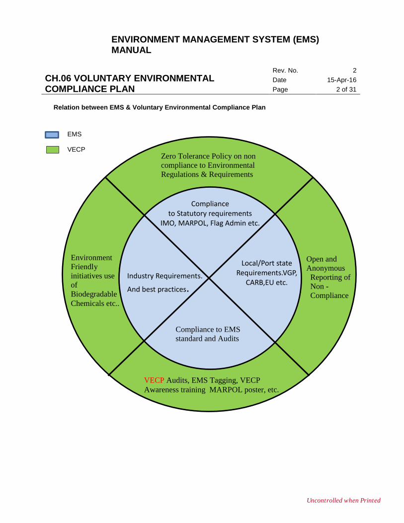
Relation between EMS & Voluntary Environmental Compliance Plan
VECP Audits, EMS Tagging, VECP
Awareness training MARPOL poster, etc.
Compliance to EMS
standard and Audits
Local/Port state Requirements.VGP,
CARB,EU etc.
Open and
Anonymous
Reporting of
Non -
Compliance
Zero Tolerance Policy on non
compliance to Environmental
Regulations & Requirements
Compliance
to Statutory requirements IMO, MARPOL, Flag Admin etc.
Industry Requirements.
And best practices.
Environment
Friendly
initiatives use
of
Biodegradable
Chemicals etc..
EMS
VECP
Uncontrolled when Printed
ENVIRONMENT MANAGEMENT SYSTEM (EMS) MANUAL
CH.06 VOLUNTARY ENVIRONMENTAL COMPLIANCE PLAN
Rev. No. 2
Date 15-Apr-16
Page 3 of 31
6.2. PROCEDURES FOR TAKING OVER A SHIP IN TO MANAGEMENT.
On taking over a ship into the management, as a minimum, the following should be checked as part
of Management of Change (MOC) and reported to office by Chief Engineer.
a. Thorough check of the Oily water Separator (OWS) to ensure its correct functioning.
b. Check of Type approval certificate of OWS.
c. Check calibration certificate and Type approval certificate of Oil Content Meter (OCM) is on
board and carry out zero check/function test.
d. Thorough search of the Engine room for any ‘magic pipes’, hoses etc. which could lead to
suspicion of MARPOL violation. If any such pipe exists, office to be informed and pipe removed
from vessel, with a clear change of custody.
e. Inspect bilge holding tank, clean up if required.
f. Inspect the OWS overboard pipeline internally, clean up if required.
g. Check maintenance routines / records for the OWS and associated machinery.
h. Check availability of critical spares for OWS and order missing spares in accordance with
company guidelines for minimum spare part requirement.
i. Check spectacle flange interconnection between bilge and Sludge system. Both systems should
be properly isolated and fitted with a tamper proof seals supplied by the company.
j. Open up and inspect direct bilge well suction filters leading to the Fire & GS and Bilge & GS
pumps. Clean up if required. Report condition before cleaning and after cleaning to the Office
with photographs.
k. Confirm that the details of the equipment, tank capacities etc. are entered correctly in the IOPP
certificate and that all bilge, sludge and drain tanks including scavenge drain tanks are included.
If there are any discrepancies found the office is to be informed of the same.
l. Check previous Oil record books, Bunker Delivery Notes (BDNs) and MARPOL Bunker samples.
Records should be available for at least last 3 years or as per Flag requirements for Oil record
books and Bunker Delivery Notes. MARPOL Bunker samples to be retained on board for 12
months or as per flag requirements.
m. Oil Record book at least copy of the same for the last 3 years to be kept on board.
n. Master/ Chief Engineer to carry out training session highlighting company’s commitment for
environment protection and procedures for same.
o. Check that all bilge / sludge pipelines are in accordance with the original yard plans. In case
there are any modifications to the original - are they Class approved? In case of any deviation
Uncontrolled when Printed
ENVIRONMENT MANAGEMENT SYSTEM (EMS) MANUAL
CH.06 VOLUNTARY ENVIRONMENTAL COMPLIANCE PLAN
Rev. No. 2
Date 15-Apr-16
Page 4 of 31
from the Original yard or Class approved plans, office must be informed immediately. In case
vessel has a set of plans that do not conform to the actual pipeline (not as per original or Class
approved) these should be destroyed to avoid any confusion.
p. Tamper proof seals to be fitted at all locations as specified in TE 41(List of general sealing
points)and records of same to be maintained as per TE37.(Summary of sealing points).
q. OWS maintenance to be carried out, photographic evidence of work done must be maintained.
r. Ozone Depleting Substances form TE 30(MARPOL Annex VI Record Book), and Garbage Log
must be started immediately.
s. Every ship taken into management with an oily water separator of the filtration type must have
minimum critical spares like spare coalescer/filter cartridges on board as per company
guidelines in Technical Manual & PMS.
t. Check the operation of Sewage treatment plant for proper functioning. Check availability of
critical spares for STP as per guidelines for minimum spare parts requirement.
u. Check the operation of W.O. Incinerator for proper functioning. Check availability of critical
spares for W.O. Incinerator as per guidelines for minimum spare parts requirement.
6.3. GUIDELINES FOR PREPARATION TO PORT STATE CONTROL INSPECTION FOR
MARPOL VIOLATIONS
a. It is most important that the authorities are escorted by the Chief Engineer and another
engineer or officer during the engine room inspection. Close communication with the Master
via Walkie-talkie must be maintained.
b. If the authorities take any samples of bilges or oil, the office to be advised immediately. The
authorities may provide the vessel with split samples (i.e. single sample drawn and divided
into two parts of which one is given to the vessel.) in case split samples are not provided,
vessel should also endeavor to take samples from the same location, seal them with the
counter-signature of all parties concerned, if the authorities agree to sign the ship’s
representative samples.
c. If the authorities take photographs of the installation and / or location form where the sample is drawn, vessel should also take similar photographs from the same viewpoint with the date, stamp on the camera operational to the local date and time. In any case, even if authorities do not take photographs the vessel must take them.
Uncontrolled when Printed
ENVIRONMENT MANAGEMENT SYSTEM (EMS) MANUAL
CH.06 VOLUNTARY ENVIRONMENTAL COMPLIANCE PLAN
Rev. No. 2
Date 15-Apr-16
Page 5 of 31
d. Records of all conversation with the authorities are to be made at the earliest convenience
to avoid missing out any details later.
Following Checks have to be carried out for preparation prior arrival Port:
- Documentation and records must be precisely and correctly maintained.
- Latest shore calibration certificate of the 15 ppm Oil content Monitor.
- Alarm test of 15 ppm equipment and operation of 3-way valve / pump stop.
- Can the effluent from the OWS, after three way valve be tested? (with overboard valve
closed)
- OWS operation; 15ppm alarm test; check of data recorded in the OCM memory card.
- General condition of bilges and seawater, oil leaks in the engine room.
- Temporary repair on OWS casing by means of cold repair.
- Temporary repair done on sewage treatment plant casing.
- Spares for OWS and bilge pumps.
- OWS maintenance records.
- Incinerator operation – test operation on waste oil.
- Sewage plant operation. Check for residual chlorine content of treated water and presence
of any floating solids in the test sample.
- Check of activated sludge return flow through the flow return tubes for the sewage treatment
plant.
- Garbage Log – special care on garbage incineration and disposal of cargo residue. Logs
maintained must reflect the actual quantity of garbage generated / disposed. Care should be
taken when filling the logs as PSC’s are looking at these more stringently.
- Verify the quantity mentioned in individual tanks in oil record book tallies with the actual
retention in each of the tanks in engine room.
- Verify the timings recorded in oil record book tallies with what is recorded in the OCM
memory card (if applicable) and/or Oil Content Meter panel of the Oily Water Separator and
the panel of Incinerator.
- Verify the alarm log print outs of the Engine Control Room printer and may check the Oil
record book entries to establish when oily water separator or incinerator were used New
Uncontrolled when Printed
ENVIRONMENT MANAGEMENT SYSTEM (EMS) MANUAL
CH.06 VOLUNTARY ENVIRONMENTAL COMPLIANCE PLAN
Rev. No. 2
Date 15-Apr-16
Page 6 of 31
version of oil record book is in use and the new codes are being used which have come into
force.
6.4. INSTALLATION AND MAINTENANCE OF TAMPER PROOF SEALS IN BILGE PIPE
LINES SYSTEM.
6.4.1. To maintain the ER bilge pipe line integrity
The main feature of this is to install numbered tamper proof seals in the ER bilge system and various
other system components as listed below and to maintain a log of all seals that are installed in
engine room at any given time in the MARPOL SEAL LOG. (Ref: Illustration No. 6.5)
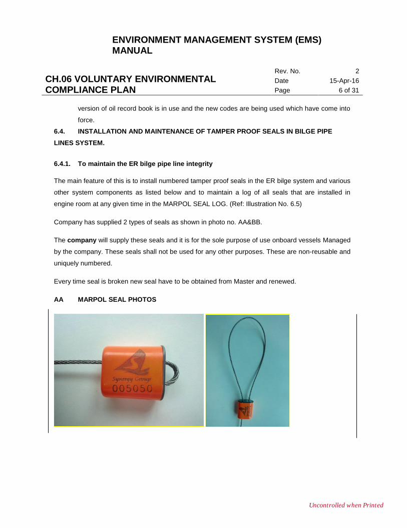
Company has supplied 2 types of seals as shown in photo no. AA&BB.
The company will supply these seals and it is for the sole purpose of use onboard vessels Managed
by the company. These seals shall not be used for any other purposes. These are non-reusable and
uniquely numbered.
Every time seal is broken new seal have to be obtained from Master and renewed.
AA MARPOL SEAL PHOTOS
Uncontrolled when Printed
ENVIRONMENT MANAGEMENT SYSTEM (EMS) MANUAL
CH.06 VOLUNTARY ENVIRONMENTAL COMPLIANCE PLAN
Rev. No. 2
Date 15-Apr-16
Page 7 of 31
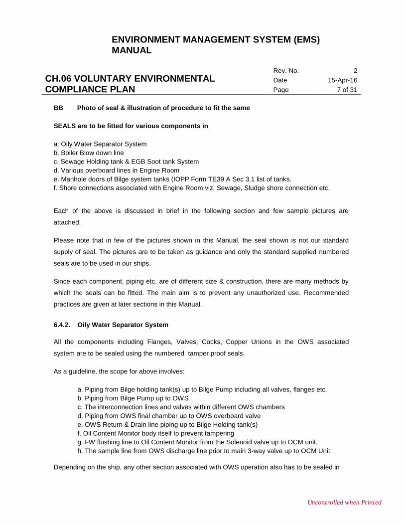
BB Photo of seal & illustration of procedure to fit the same
SEALS are to be fitted for various components in
a. Oily Water Separator System
b. Boiler Blow down line
c. Sewage Holding tank & EGB Soot tank System
d. Various overboard lines in Engine Room
e. Manhole doors of Bilge system tanks (IOPP Form TE39 A Sec 3.1 list of tanks.
f. Shore connections associated with Engine Room viz. Sewage, Sludge shore connection etc.
Each of the above is discussed in brief in the following section and few sample pictures are
attached.
Please note that in few of the pictures shown in this Manual, the seal shown is not our standard
supply of seal. The pictures are to be taken as guidance and only the standard supplied numbered
seals are to be used in our ships.
Since each component, piping etc. are of different size & construction, there are many methods by
which the seals can be fitted. The main aim is to prevent any unauthorized use. Recommended
practices are given at later sections in this Manual..
6.4.2. Oily Water Separator System
All the components including Flanges, Valves, Cocks, Copper Unions in the OWS associated
system are to be sealed using the numbered tamper proof seals.
As a guideline, the scope for above involves:
a. Piping from Bilge holding tank(s) up to Bilge Pump including all valves, flanges etc.
b. Piping from Bilge Pump up to OWS
c. The interconnection lines and valves within different OWS chambers
d. Piping from OWS final chamber up to OWS overboard valve
e. OWS Return & Drain line piping up to Bilge Holding tank(s)
f. Oil Content Monitor body itself to prevent tampering
g. FW flushing line to Oil Content Monitor from the Solenoid valve up to OCM unit.
h. The sample line from OWS discharge line prior to main 3-way valve up to OCM Unit
Depending on the ship, any other section associated with OWS operation also has to be sealed in
Uncontrolled when Printed
ENVIRONMENT MANAGEMENT SYSTEM (EMS) MANUAL
CH.06 VOLUNTARY ENVIRONMENTAL COMPLIANCE PLAN
Rev. No. 2
Date 15-Apr-16
Page 8 of 31
such a manner so as to prevent unauthorized usage. Following guidelines can be used to seal small sections of copper piping like
a. 3-way copper piping b. Ball valve connection c. Inlet piping for Oil Content Monitor d. Small ferrules, copper unions etc. in copper piping.
The pictures give just an idea of how to go about. Vessel staff should take this guidance and to seal
the components in a thoughtful way suiting the particular location in order to prevent the
unauthorized opening.
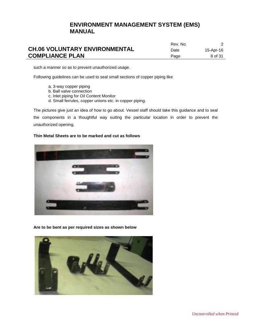
Thin Metal Sheets are to be marked and cut as follows
Are to be bent as per required sizes as shown below
Uncontrolled when Printed
ENVIRONMENT MANAGEMENT SYSTEM (EMS) MANUAL
CH.06 VOLUNTARY ENVIRONMENTAL COMPLIANCE PLAN
Rev. No. 2
Date 15-Apr-16
Page 9 of 31
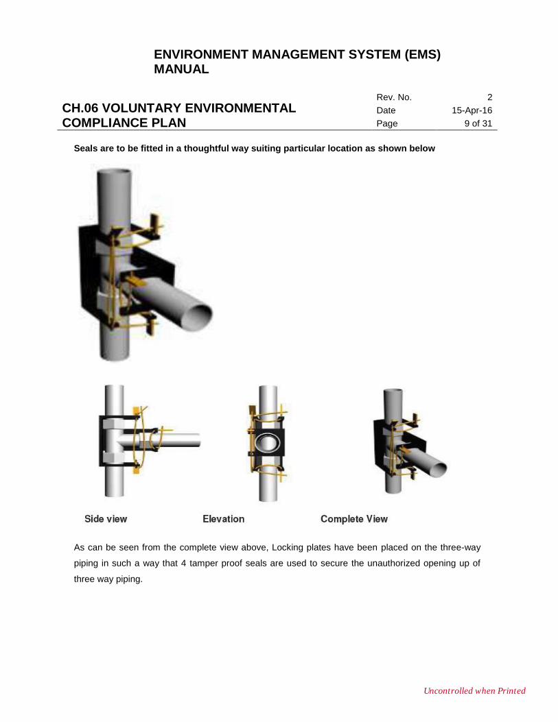
Seals are to be fitted in a thoughtful way suiting particular location as shown below
As can be seen from the complete view above, Locking plates have been placed on the three-way
piping in such a way that 4 tamper proof seals are used to secure the unauthorized opening up of
three way piping.
Uncontrolled when Printed
ENVIRONMENT MANAGEMENT SYSTEM (EMS) MANUAL
CH.06 VOLUNTARY ENVIRONMENTAL COMPLIANCE PLAN
Rev. No. 2
Date 15-Apr-16
Page 10 of 31
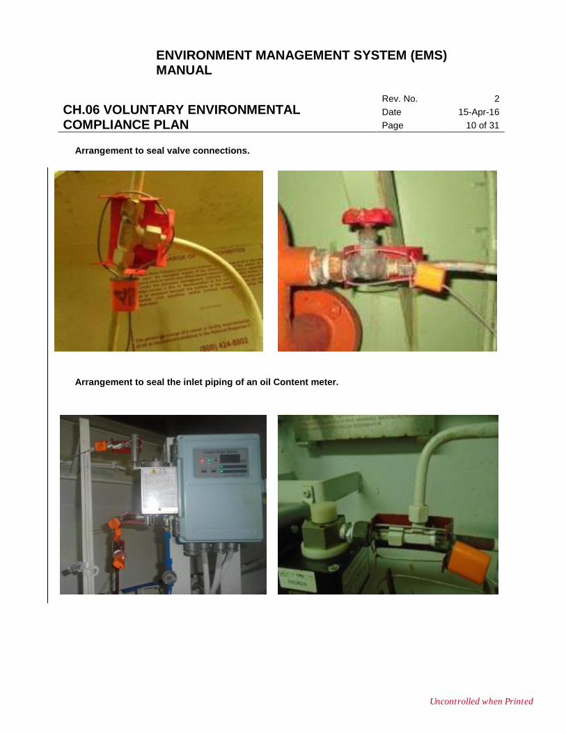
Arrangement to seal valve connections.
Arrangement to seal the inlet piping of an oil Content meter.
Uncontrolled when Printed
ENVIRONMENT MANAGEMENT SYSTEM (EMS) MANUAL
CH.06 VOLUNTARY ENVIRONMENTAL COMPLIANCE PLAN
Rev. No. 2
Date 15-Apr-16
Page 11 of 31
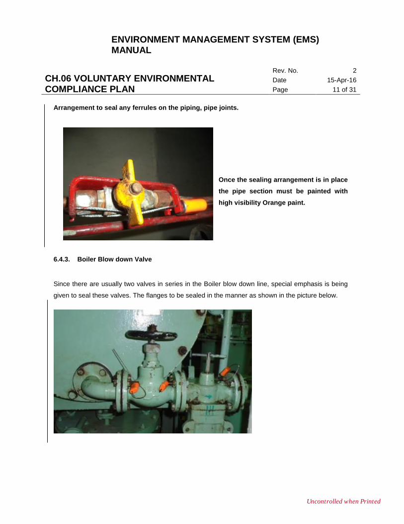
Arrangement to seal any ferrules on the piping, pipe joints.
Once the sealing arrangement is in place
the pipe section must be painted with
high visibility Orange paint.
6.4.3. Boiler Blow down Valve
Since there are usually two valves in series in the Boiler blow down line, special emphasis is being
given to seal these valves. The flanges to be sealed in the manner as shown in the picture below.
Uncontrolled when Printed
ENVIRONMENT MANAGEMENT SYSTEM (EMS) MANUAL
CH.06 VOLUNTARY ENVIRONMENTAL COMPLIANCE PLAN
Rev. No. 2
Date 15-Apr-16
Page 12 of 31
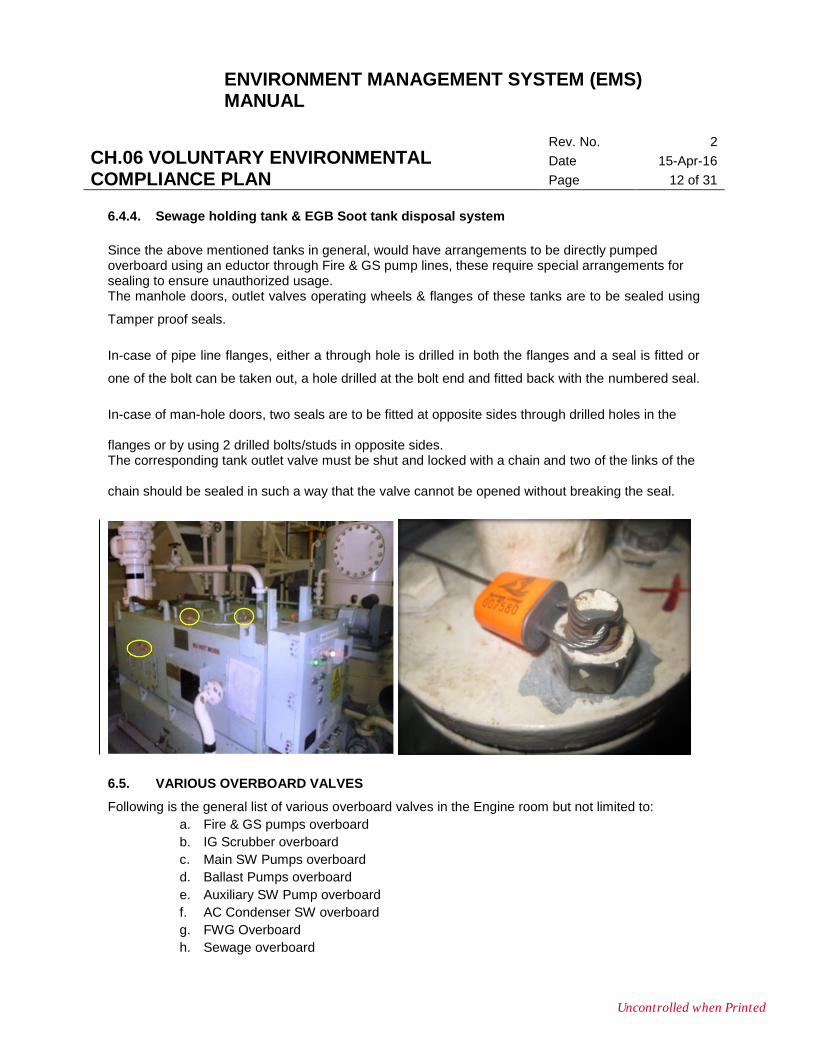
6.4.4. Sewage holding tank & EGB Soot tank disposal system
Since the above mentioned tanks in general, would have arrangements to be directly pumped overboard using an eductor through Fire & GS pump lines, these require special arrangements for sealing to ensure unauthorized usage. The manhole doors, outlet valves operating wheels & flanges of these tanks are to be sealed using
Tamper proof seals.
In-case of pipe line flanges, either a through hole is drilled in both the flanges and a seal is fitted or
one of the bolt can be taken out, a hole drilled at the bolt end and fitted back with the numbered seal.
In-case of man-hole doors, two seals are to be fitted at opposite sides through drilled holes in the flanges or by using 2 drilled bolts/studs in opposite sides. The corresponding tank outlet valve must be shut and locked with a chain and two of the links of the chain should be sealed in such a way that the valve cannot be opened without breaking the seal.
6.5. VARIOUS OVERBOARD VALVES
Following is the general list of various overboard valves in the Engine room but not limited to:
a. Fire & GS pumps overboard
b. IG Scrubber overboard
c. Main SW Pumps overboard
d. Ballast Pumps overboard
e. Auxiliary SW Pump overboard
f. AC Condenser SW overboard
g. FWG Overboard
h. Sewage overboard
Uncontrolled when Printed
ENVIRONMENT MANAGEMENT SYSTEM (EMS) MANUAL
CH.06 VOLUNTARY ENVIRONMENTAL COMPLIANCE PLAN
Rev. No. 2
Date 15-Apr-16
Page 13 of 31
i. Galley disposer overboard
j. Grey Water overboard
k. Hospital Drain overboard.
l. Eductor overboard
m. Soot Collection tank Eductor Overboard etc.
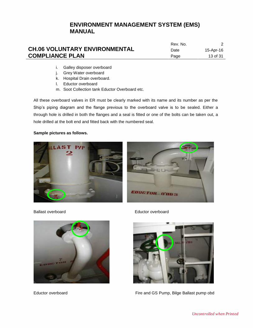
All these overboard valves in ER must be clearly marked with its name and its number as per the
Ship’s piping diagram and the flange previous to the overboard valve is to be sealed. Either a
through hole is drilled in both the flanges and a seal is fitted or one of the bolts can be taken out, a
hole drilled at the bolt end and fitted back with the numbered seal.
Sample pictures as follows.
Ballast overboard Eductor overboard
Eductor overboard Fire and GS Pump, Bilge Ballast pump obd
Uncontrolled when Printed
ENVIRONMENT MANAGEMENT SYSTEM (EMS) MANUAL
CH.06 VOLUNTARY ENVIRONMENTAL COMPLIANCE PLAN
Rev. No. 2
Date 15-Apr-16
Page 14 of 31
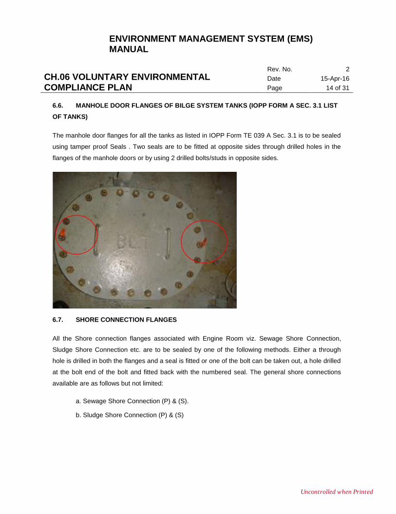
6.6. MANHOLE DOOR FLANGES OF BILGE SYSTEM TANKS (IOPP FORM A SEC. 3.1 LIST
OF TANKS)
The manhole door flanges for all the tanks as listed in IOPP Form TE 039 A Sec. 3.1 is to be sealed
using tamper proof Seals . Two seals are to be fitted at opposite sides through drilled holes in the
flanges of the manhole doors or by using 2 drilled bolts/studs in opposite sides.
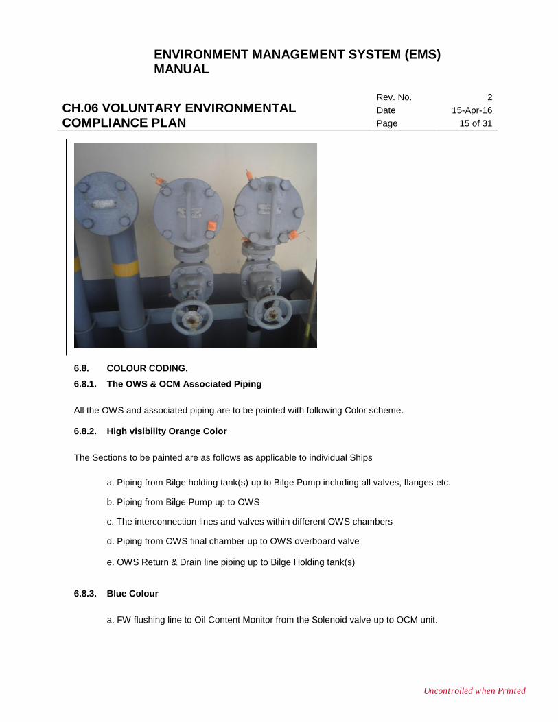
6.7. SHORE CONNECTION FLANGES
All the Shore connection flanges associated with Engine Room viz. Sewage Shore Connection,
Sludge Shore Connection etc. are to be sealed by one of the following methods. Either a through
hole is drilled in both the flanges and a seal is fitted or one of the bolt can be taken out, a hole drilled
at the bolt end of the bolt and fitted back with the numbered seal. The general shore connections
available are as follows but not limited:
a. Sewage Shore Connection (P) & (S).
b. Sludge Shore Connection (P) & (S)
Uncontrolled when Printed
ENVIRONMENT MANAGEMENT SYSTEM (EMS) MANUAL
CH.06 VOLUNTARY ENVIRONMENTAL COMPLIANCE PLAN
Rev. No. 2
Date 15-Apr-16
Page 15 of 31
6.8. COLOUR CODING.
6.8.1. The OWS & OCM Associated Piping
All the OWS and associated piping are to be painted with following Color scheme. 6.8.2. High visibility Orange Color
The Sections to be painted are as follows as applicable to individual Ships
a. Piping from Bilge holding tank(s) up to Bilge Pump including all valves, flanges etc.
b. Piping from Bilge Pump up to OWS
c. The interconnection lines and valves within different OWS chambers
d. Piping from OWS final chamber up to OWS overboard valve e. OWS Return & Drain line piping up to Bilge Holding tank(s)
6.8.3. Blue Colour
a. FW flushing line to Oil Content Monitor from the Solenoid valve up to OCM unit.
Uncontrolled when Printed
ENVIRONMENT MANAGEMENT SYSTEM (EMS) MANUAL
CH.06 VOLUNTARY ENVIRONMENTAL COMPLIANCE PLAN
Rev. No. 2
Date 15-Apr-16
Page 16 of 31
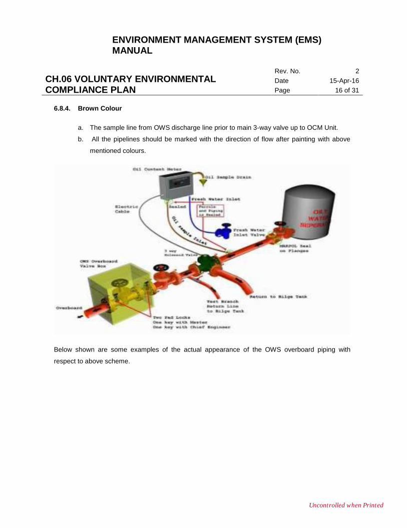
6.8.4. Brown Colour
a. The sample line from OWS discharge line prior to main 3-way valve up to OCM Unit.
b. All the pipelines should be marked with the direction of flow after painting with above
mentioned colours.
Below shown are some examples of the actual appearance of the OWS overboard piping with
respect to above scheme.
Uncontrolled when Printed
ENVIRONMENT MANAGEMENT SYSTEM (EMS) MANUAL
CH.06 VOLUNTARY ENVIRONMENTAL COMPLIANCE PLAN
Rev. No. 2
Date 15-Apr-16
Page 17 of 31
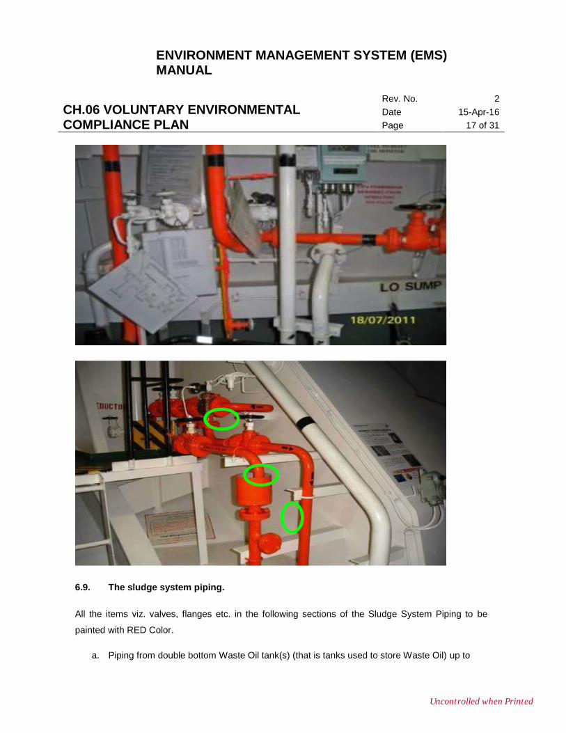
6.9. The sludge system piping.
All the items viz. valves, flanges etc. in the following sections of the Sludge System Piping to be
painted with RED Color.
a. Piping from double bottom Waste Oil tank(s) (that is tanks used to store Waste Oil) up to
Uncontrolled when Printed
ENVIRONMENT MANAGEMENT SYSTEM (EMS) MANUAL
CH.06 VOLUNTARY ENVIRONMENTAL COMPLIANCE PLAN
Rev. No. 2
Date 15-Apr-16
Page 18 of 31
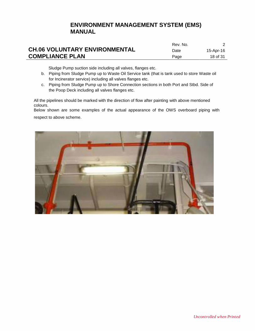
Sludge Pump suction side including all valves, flanges etc.
b. Piping from Sludge Pump up to Waste Oil Service tank (that is tank used to store Waste oil
for Incinerator service) including all valves flanges etc.
c. Piping from Sludge Pump up to Shore Connection sections in both Port and Stbd. Side of
the Poop Deck including all valves flanges etc.
All the pipelines should be marked with the direction of flow after painting with above mentioned colours. Below shown are some examples of the actual appearance of the OWS overboard piping with
respect to above scheme.
Uncontrolled when Printed
ENVIRONMENT MANAGEMENT SYSTEM (EMS) MANUAL
CH.06 VOLUNTARY ENVIRONMENTAL COMPLIANCE PLAN
Rev. No. 2
Date 15-Apr-16
Page 19 of 31
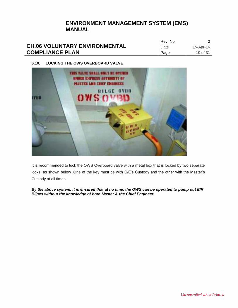
6.10. LOCKING THE OWS OVERBOARD VALVE
It is recommended to lock the OWS Overboard valve with a metal box that is locked by two separate
locks, as shown below .One of the key must be with C/E’s Custody and the other with the Master’s
Custody at all times.
By the above system, it is ensured that at no time, the OWS can be operated to pump out E/R Bilges without the knowledge of both Master & the Chief Engineer.
Uncontrolled when Printed
ENVIRONMENT MANAGEMENT SYSTEM (EMS) MANUAL
CH.06 VOLUNTARY ENVIRONMENTAL COMPLIANCE PLAN
Rev. No. 2
Date 15-Apr-16
Page 20 of 31
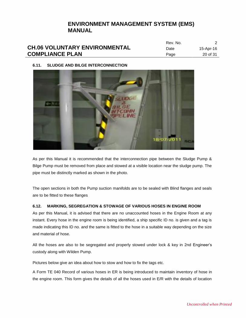
6.11. SLUDGE AND BILGE INTERCONNECTION
As per this Manual it is recommended that the interconnection pipe between the Sludge Pump &
Bilge Pump must be removed from place and stowed at a visible location near the sludge pump. The
pipe must be distinctly marked as shown in the photo.
The open sections in both the Pump suction manifolds are to be sealed with Blind flanges and seals
are to be fitted to these flanges
6.12. MARKING, SEGREGATION & STOWAGE OF VARIOUS HOSES IN ENGINE ROOM
As per this Manual, it is advised that there are no unaccounted hoses in the Engine Room at any
instant. Every hose in the engine room is being identified, a ship specific ID no. is given and a tag is
made indicating this ID no. and the same is fitted to the hose in a suitable way depending on the size
and material of hose.
All the hoses are also to be segregated and properly stowed under lock & key in 2nd Engineer’s
custody along with Wilden Pump.
Pictures below give an idea about how to stow and how to fix the tags etc. A Form TE 040 Record of various hoses in ER is being introduced to maintain inventory of hose in
the engine room. This form gives the details of all the hoses used in E/R with the details of location
Uncontrolled when Printed

ENVIRONMENT MANAGEMENT SYSTEM (EMS) MANUAL
CH.06 VOLUNTARY ENVIRONMENTAL COMPLIANCE PLAN
Rev. No. 2
Date 15-Apr-16
Page 21 of 31
and application etc. Any hose that is newly put in use should be entered in this form and any hose
that is taken out of service is also to be entered as“DISCARDED”in the remarks column.
Various hoses used in Engine room are as follows but not limited up to
1. Hose for general Air/Water service
2. Hose for used oil, sludge transfers while cleaning tanks, LO sumps etc.
3. Hose for Oxygen & Acetylene Gas cutting operations
4. Hose for cleaning of Heat exchangers by Chemical Circulation method.
Illustrations for different methods to Tag the Hoses
Uncontrolled when Printed
ENVIRONMENT MANAGEMENT SYSTEM (EMS) MANUAL
CH.06 VOLUNTARY ENVIRONMENTAL COMPLIANCE PLAN
Rev. No. 2
Date 15-Apr-16
Page 22 of 31
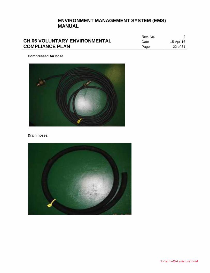
Compressed Air hose
.
Drain hoses.
Uncontrolled when Printed
ENVIRONMENT MANAGEMENT SYSTEM (EMS) MANUAL
CH.06 VOLUNTARY ENVIRONMENTAL COMPLIANCE PLAN
Rev. No. 2
Date 15-Apr-16
Page 23 of 31
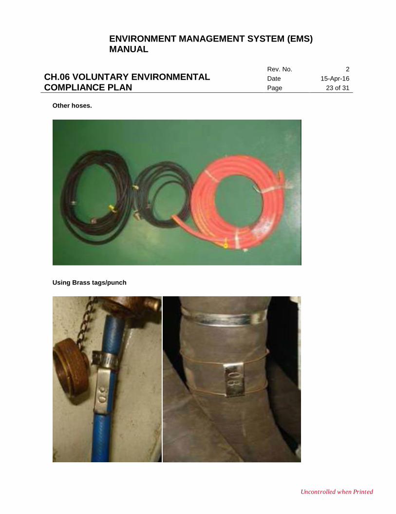
Other hoses.
Using Brass tags/punch
Uncontrolled when Printed
ENVIRONMENT MANAGEMENT SYSTEM (EMS) MANUAL
CH.06 VOLUNTARY ENVIRONMENTAL COMPLIANCE PLAN
Rev. No. 2
Date 15-Apr-16
Page 24 of 31
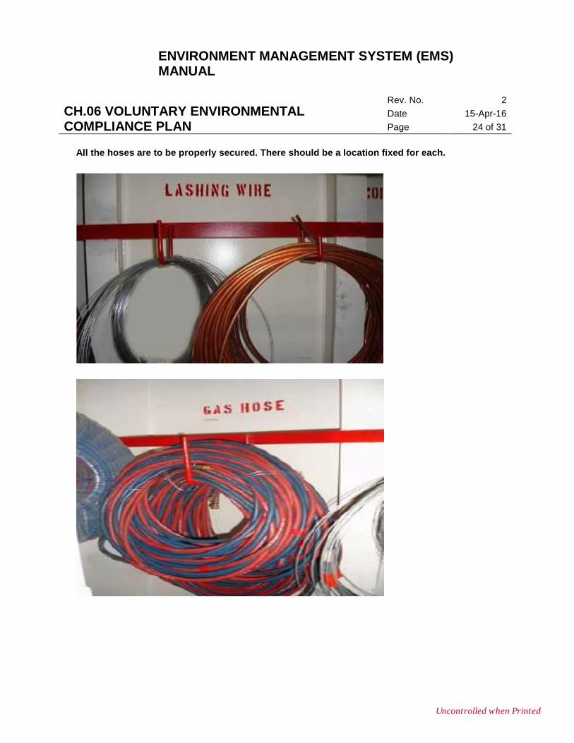
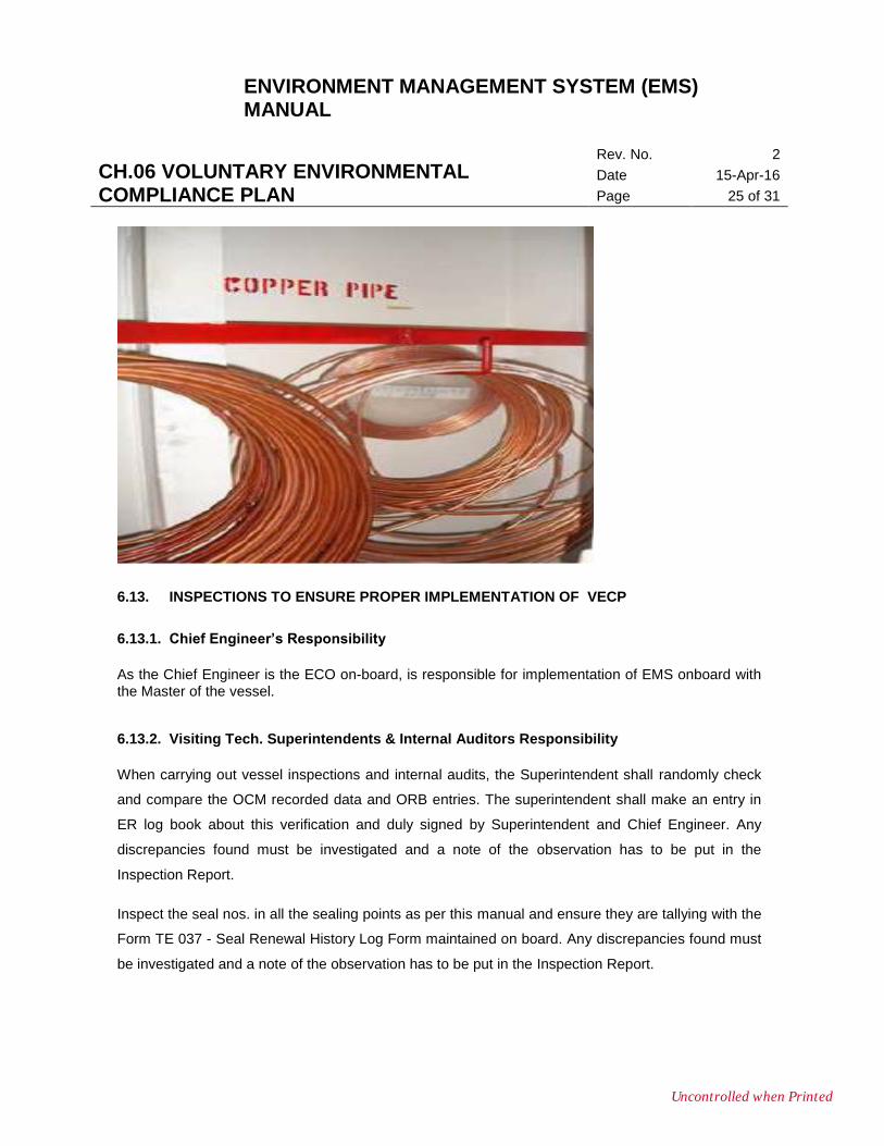
All the hoses are to be properly secured. There should be a location fixed for each.
Uncontrolled when Printed
ENVIRONMENT MANAGEMENT SYSTEM (EMS) MANUAL
CH.06 VOLUNTARY ENVIRONMENTAL COMPLIANCE PLAN
Rev. No. 2
Date 15-Apr-16
Page 25 of 31
6.13. INSPECTIONS TO ENSURE PROPER IMPLEMENTATION OF VECP
6.13.1. Chief Engineer’s Responsibility
As the Chief Engineer is the ECO on-board, is responsible for implementation of EMS onboard with the Master of the vessel.
6.13.2. Visiting Tech. Superintendents & Internal Auditors Responsibility
When carrying out vessel inspections and internal audits, the Superintendent shall randomly check
and compare the OCM recorded data and ORB entries. The superintendent shall make an entry in
ER log book about this verification and duly signed by Superintendent and Chief Engineer. Any
discrepancies found must be investigated and a note of the observation has to be put in the
Inspection Report.
Inspect the seal nos. in all the sealing points as per this manual and ensure they are tallying with the
Form TE 037 - Seal Renewal History Log Form maintained on board. Any discrepancies found must
be investigated and a note of the observation has to be put in the Inspection Report.
Uncontrolled when Printed
ENVIRONMENT MANAGEMENT SYSTEM (EMS) MANUAL
CH.06 VOLUNTARY ENVIRONMENTAL COMPLIANCE PLAN
Rev. No. 2
Date 15-Apr-16
Page 26 of 31
Inspect the internal condition of Bilge Holding tank and OWS and a note of the observation to be put
in the Inspection Report.
6.13.3. Taking Over Chief Engineer’s responsibility
At the time of change of Chief Engineer, incoming Chief Engineer must:
Inspect the condition of Bilge Holding tank and OWS prior to take over. To facilitate this,Bilge holding
tank and OWS shall be kept opened immediately upon berthing where there is a change of Chief
Engineer. Once inspected, suitable entries to be made in ER log book duly signed by Outgoing CE
and Incoming CE. Any discrepancies found must be brought to the attention of Technical
Superintendent as early as possible.
Inspect the seal nos. in all the sealing points and ensure they are tallying with the TE 037 Seal
Renewal History Log Form maintained on board. Any discrepancies found must be brought to the
attention of EMS Cell and Technical Superintendent as early as possible. The TE 037 Seal Renewal
History Log Form should be endorsed by taking over C/E and send to Ems Cell.Randomly check
and compare the OCM recorded data and ORB entries. The incoming CE shall make an entry in ER
log book about this verification. Any discrepancies found must be brought to the attention of
Technical Superintendent as early as possible.
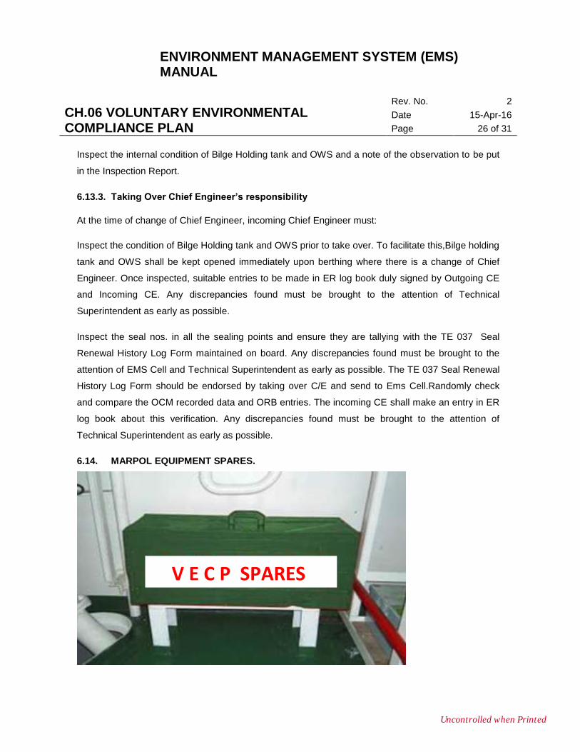
6.14. MARPOL EQUIPMENT SPARES.
V E C P SPARES
Uncontrolled when Printed
ENVIRONMENT MANAGEMENT SYSTEM (EMS) MANUAL
CH.06 VOLUNTARY ENVIRONMENTAL COMPLIANCE PLAN
Rev. No. 2
Date 15-Apr-16
Page 27 of 31
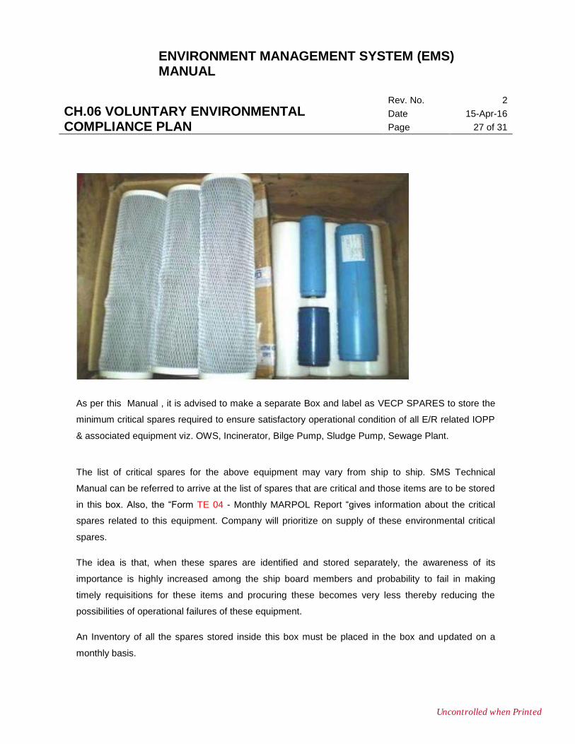
As per this Manual , it is advised to make a separate Box and label as VECP SPARES to store the
minimum critical spares required to ensure satisfactory operational condition of all E/R related IOPP
& associated equipment viz. OWS, Incinerator, Bilge Pump, Sludge Pump, Sewage Plant.
The list of critical spares for the above equipment may vary from ship to ship. SMS Technical
Manual can be referred to arrive at the list of spares that are critical and those items are to be stored
in this box. Also, the “Form TE 04 - Monthly MARPOL Report “gives information about the critical
spares related to this equipment. Company will prioritize on supply of these environmental critical
spares.
The idea is that, when these spares are identified and stored separately, the awareness of its
importance is highly increased among the ship board members and probability to fail in making
timely requisitions for these items and procuring these becomes very less thereby reducing the
possibilities of operational failures of these equipment.
An Inventory of all the spares stored inside this box must be placed in the box and updated on a
monthly basis.
Uncontrolled when Printed
ENVIRONMENT MANAGEMENT SYSTEM (EMS) MANUAL
CH.06 VOLUNTARY ENVIRONMENTAL COMPLIANCE PLAN
Rev. No. 2
Date 15-Apr-16
Page 28 of 31
Also monthly MARPOL report is to be made and forwarded to the technical Superintendent
regarding the condition of the pollution prevention equipment on board with the points that require
special attention in the remarks columns.
6.14.1. PROMINENT MARKING OF INTERCONNECTION VALVES WITH ER BILGE SYSTEM
Prominent Marking of Valves that are interconnected with ER Bilge System that are to be regularly
operated for either Testing or Operational purposes viz.
a. Emergency Bilge Suction
b. Direct Bilge Suction
c. Cargo holds Bilge Suction
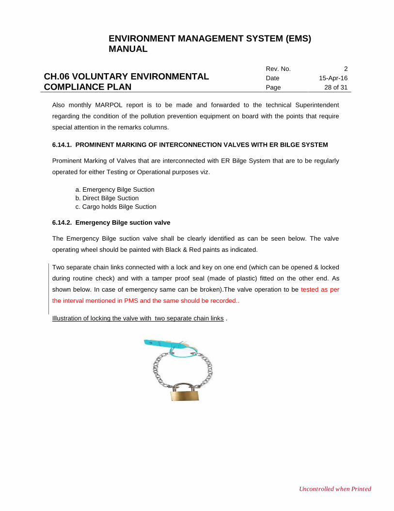
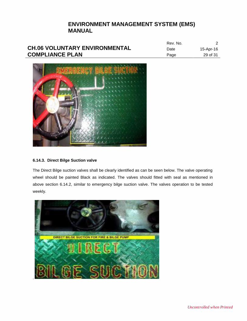
6.14.2. Emergency Bilge suction valve
The Emergency Bilge suction valve shall be clearly identified as can be seen below. The valve
operating wheel should be painted with Black & Red paints as indicated.
Two separate chain links connected with a lock and key on one end (which can be opened & locked
during routine check) and with a tamper proof seal (made of plastic) fitted on the other end. As
shown below. In case of emergency same can be broken).The valve operation to be tested as per
the interval mentioned in PMS and the same should be recorded..
Illustration of locking the valve with two separate chain links .
Uncontrolled when Printed
ENVIRONMENT MANAGEMENT SYSTEM (EMS) MANUAL
CH.06 VOLUNTARY ENVIRONMENTAL COMPLIANCE PLAN
Rev. No. 2
Date 15-Apr-16
Page 29 of 31
6.14.3. Direct Bilge Suction valve
The Direct Bilge suction valves shall be clearly identified as can be seen below. The valve operating
wheel should be painted Black as indicated. The valves should fitted with seal as mentioned in
above section 6.14.2, similar to emergency bilge suction valve. The valves operation to be tested
weekly.
.
Uncontrolled when Printed
ENVIRONMENT MANAGEMENT SYSTEM (EMS) MANUAL
CH.06 VOLUNTARY ENVIRONMENTAL COMPLIANCE PLAN
Rev. No. 2
Date 15-Apr-16
Page 30 of 31
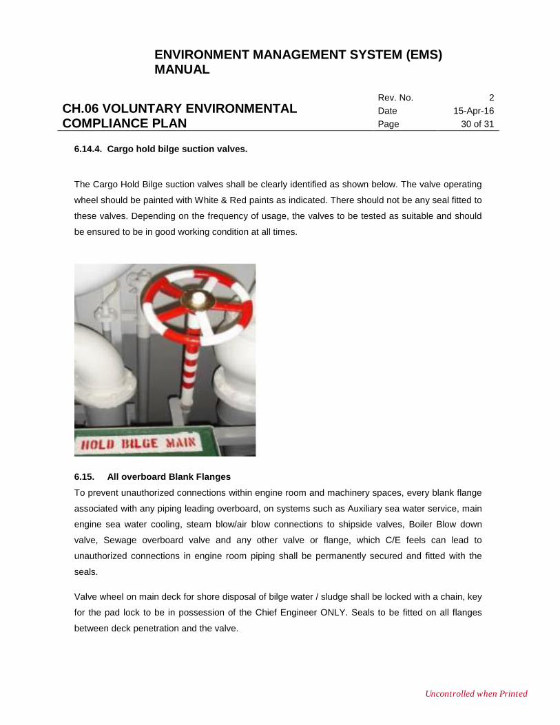
6.14.4. Cargo hold bilge suction valves.
The Cargo Hold Bilge suction valves shall be clearly identified as shown below. The valve operating
wheel should be painted with White & Red paints as indicated. There should not be any seal fitted to
these valves. Depending on the frequency of usage, the valves to be tested as suitable and should
be ensured to be in good working condition at all times.
6.15. All overboard Blank Flanges
To prevent unauthorized connections within engine room and machinery spaces, every blank flange
associated with any piping leading overboard, on systems such as Auxiliary sea water service, main
engine sea water cooling, steam blow/air blow connections to shipside valves, Boiler Blow down
valve, Sewage overboard valve and any other valve or flange, which C/E feels can lead to
unauthorized connections in engine room piping shall be permanently secured and fitted with the
seals.
Valve wheel on main deck for shore disposal of bilge water / sludge shall be locked with a chain, key
for the pad lock to be in possession of the Chief Engineer ONLY. Seals to be fitted on all flanges
between deck penetration and the valve.
Uncontrolled when Printed
ENVIRONMENT MANAGEMENT SYSTEM (EMS) MANUAL
CH.06 VOLUNTARY ENVIRONMENTAL COMPLIANCE PLAN
Rev. No. 2
Date 15-Apr-16
Page 31 of 31
6.15.1 INVENTORY CONTROL OF SEALS
a. The Chief engineer shall keep a record of TE 37 when the seals are fitted. This record shall
be a part of the Masters/Chief Engineer Handover notes.
b. The Master shall retain the new replacement seals. Proper records of seals issued must be
kept in Seal inventory log (TE-38A).
c. If a seal has to be broken for any reason (maintenance, etc.), details of the reasons and new
seal number fitted to be entered, record (TE 38 Seals renewal log) maintained.
d. Record of seal numbers used along with their location shall be maintained by the Chief
Engineer. (TE 37 Summary of sealing points).
e. Vessel should prepare a ship specific schematic diagram identifying all relevant flanges and
valves. The flanges and valves are to be identified in numerical order (Starting with “1” from
the 1st flange on Oily Water Separator bilge pump discharge side). This diagram shall be
maintained.
f. The integrity of the seals should be checked on a 3-monthly basis by the Chief Engineer.
Entries of checks done must be made in the “Engine Room Log Book”
g. In case any evidence of tampering of seals is noticed, management office and the
Environmental Compliance officer should be informed immediately and investigation should
be carried out onboard.
h. The seals will be checked at random during Superintendent and internal auditor visits.
6.16. PROCEDURE FOR OPEN REPORTING OF NON COMPLIANCE
ENVIRONMENTAL COMPLIANCE OFFICER
The chief engineer shall be the designated environmental compliance officer (eco) on board and is
fully responsible for the implementation of the environmental compliance policy on board. The duties
and responsibilities of the environmental compliance officer are laid down in EMS manual.
ENVIRONMENTAL COMPLIANCE DECLARATION FORMS (Form M-29)
a. At the time of sign-on, each crew member shall sign a declaration in writing that they are
aware of company`s Environmental Management System and completed forms are to be
retained on board.
b. Environmental compliance declaration forms should be retained on board in Master’s
custody for 3 years after the date of sign off of the ship’s staff.
Uncontrolled when Printed