Embed Size (px)
Citation preview
Environment and Social Due Diligence Report (Appendix 4A)
August 2017
IND: Clean Energy Finance Investment Program –Orange Anantapur Wind Power Pvt. Ltd. Prepared by Indian Renewable Energy Development Agency for the Asian Development Bank This report is a document of the borrower. The views expressed herein do not necessarily represent those of ADB's Board of Directors, Management, or staff, and may be preliminary in nature. In preparing any country program or strategy, financing any project, or by making any designation of or reference to a particular territory or geographic area in this document, the Asian Development Bank does not intend to make any judgments as to the legal or other status of any territory or area.

Annexure 4
Copy of ESIA Report
106
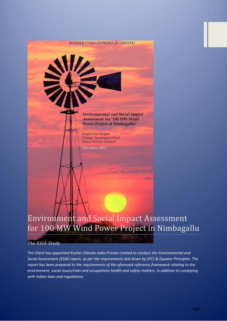
Environment and Social Impact Assessment for MW Wind Power Project in NimbagalluThe ESIA Study
The Client has appointed Kosher Climate India Private Limited to conduct the Environmental and
Social Assessment (ESIA) report, as per the requirements laid down by (IFC) & Equator Principles. The
report has been prepared to the requirements of the aforesaid reference framework relating to the
environment, social issues/risks and occupations health and safety matters, in addition to complying
with Indian laws and regulations.
107
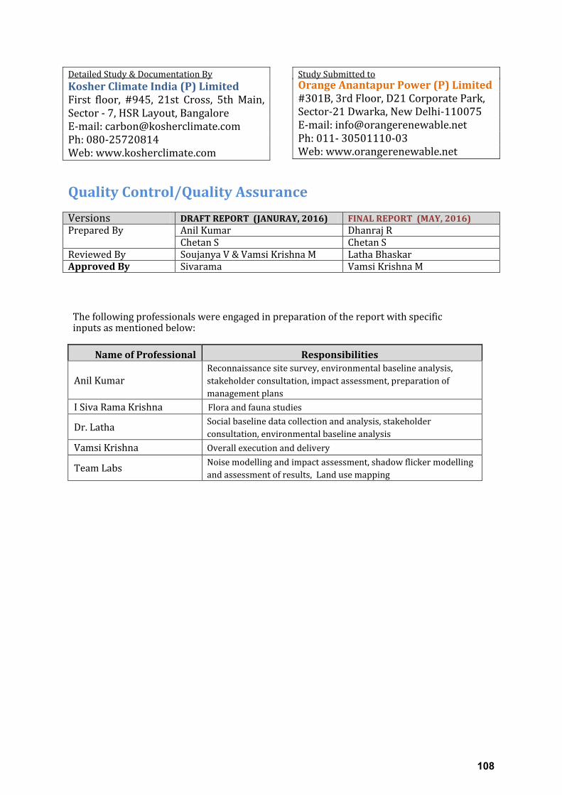
Detailed Study & Documentation By
Kosher Climate India (P) Limited
First floor, #945, 21st Cross, 5th Main,
Sector - 7, HSR Layout, Bangalore
E-mail: [email protected]
Ph: 080-25720814
Web: www.kosherclimate.com
Study Submitted to
Orange Anantapur Power (P) Limited
#301B, 3rd Floor, D21 Corporate Park,
Sector-21 Dwarka, New Delhi-110075
E-mail: [email protected]
Ph: 011- 30501110-03
Web: www.orangerenewable.net
Quality Control/Quality Assurance Versions DRAFT REPORT (JANURAY, 2016) FINAL REPORT (MAY, 2016) Prepared By Anil Kumar Dhanraj R
Chetan S Chetan S
Reviewed By Soujanya V & Vamsi Krishna M Latha Bhaskar
Approved By Sivarama Vamsi Krishna M
The following professionals were engaged in preparation of the report with specific inputs as mentioned below:
Name of Professional Responsibilities
Anil Kumar
Reconnaissance site survey, environmental baseline analysis,
stakeholder consultation, impact assessment, preparation of
management plans
I Siva Rama Krishna Flora and fauna studies
Dr. Latha Social baseline data collection and analysis, stakeholder
consultation, environmental baseline analysis
Vamsi Krishna Overall execution and delivery
Team Labs Noise modelling and impact assessment, shadow flicker modelling
and assessment of results, Land use mapping
108
1 | P a g e
Table of Content
Table of Contents 1) EXECUTIVE SUMMARY .............................................................................................................. 11
2) INTRODUCTION ......................................................................................................................... 12
2.1 Project Brief .......................................................................................................................... 12
2.2 Project Overview ................................................................................................................... 13
2.3 Implementation Progress...................................................................................................... 14
2.4 Scope Of This Study ............................................................................................................... 12
2.5 Purpose of the Study ............................................................................................................. 14
2.6 Objective of the Study .......................................................................................................... 14
2.7 Limitations of the Study ........................................................................................................ 14
2.8 Approach and Methodology ................................................................................................. 15
2.9 Agencies Contacted............................................................................................................... 18
2.10 Report Structure ................................................................................................................... 19
3) PROJECT DESCRIPTION .............................................................................................................. 19
3.1 Overview: .............................................................................................................................. 19
3.2 Site Setting: ........................................................................................................................... 20
3.3 Location Description and key feature of the project site: .................................................... 25
3.4 Project Components: ............................................................................................................ 26
3.4.1 Wind Turbine Generators ............................................................................................. 26
3.4.2 Pooling Substation (Power Evacuation) & Transmission Line:...................................... 29
3.4.3 Access Road ................................................................................................................... 33
3.4.4 Storage Yard .................................................................................................................. 36
3.5 Summary of Activities ........................................................................................................... 36
3.5.1 Conceptualization Phase: .............................................................................................. 36
3.5.2 Construction Phase ....................................................................................................... 37
3.5.3 Operation & Maintenance ............................................................................................ 37
3.5.4 Decommissioning .......................................................................................................... 37
3.6 Resource Management ......................................................................................................... 38
3.6.1 Construction Phase ....................................................................................................... 38
3.6.2 Operational Phase: ........................................................................................................ 43
3.7 Benefits of The Project .......................................................................................................... 44
3.8 Energy Assessment: .............................................................................................................. 45
109
2 | P a g e
3.9 Organizational Structure ....................................................................................................... 49
3.10 Tentative Project Schedule ................................................................................................... 50
3.11 Corporate Policies ................................................................................................................. 54
3.11.1 Corporate Policies of ANPWPL: ..................................................................................... 54
3.11.2 Corporate Policies of Gamesa ....................................................................................... 54
4 POLICY, LEGAL, AND ADMINISTRATIVE FRAME WORK ............................................................. 57
4.2 Introduction: ......................................................................................................................... 57
4.2 Enforcement Agencies of Relevant to the Project: ............................................................... 57
4.3 Applicable Laws, Policies and Regulations on Environment and Social Structure................ 61
4.4 IFC Performance Standards................................................................................................... 71
4.5 Equator Principles (by the Equator Principles Financial Institutions) ................................... 80
4.6 EHS Guidelines of IFC ............................................................................................................ 84
4.7 Categorization of the Project ................................................................................................ 93
4.8 Applicable Environment Standards ....................................................................................... 94
4.8.1 Ambient Air Quality ....................................................................................................... 94
4.8.2 Water Quality Standards ............................................................................................... 96
4.8.3 Ambient Noise Standards ............................................................................................. 99
4.8.4 Noise Standards for Occupational Exposure ................................................................. 99
4.9 International Conventions & Legislations ........................................................................... 101
5 ANALYSIS OF ALTERNATIVES ................................................................................................... 103
5.1 No Project Scenario;............................................................................................................ 103
5.2 Power Scenario in Andhra Pradesh ..................................................................................... 105
5.3 Alternate Location for the Proposed Project Site ............................................................... 106
5.4 Alternate Methods of Power Generation ........................................................................... 107
5.5 Statutory and Policy Requirements .................................................................................... 109
5.6 Alternative Technologies within Wind: ............................................................................... 111
5.7 Alternate Route for Transmission Line ............................................................................... 112
5.8 Conclusion ........................................................................................................................... 113
6 STAKEHOLDER MAPPING AND ENGAGEMENT ....................................................................... 114
6.1 Stakeholder Identification................................................................................................... 114
6.2 Stakeholder Analysis (Categorization) ................................................................................ 115
6.3 “takeholde s Co sultatio a d Dis losu e ‘e ui e e t .................................................. 121
6.3.1 Disclosure Requirement: ............................................................................................. 121
6.3.2 Process of Information Disclosure .............................................................................. 122
110
3 | P a g e
6.3.3 Stakeholder Engagement ............................................................................................ 122
7 DESCRIPTION OF ENVIRONEMENT ......................................................................................... 127
7.1 Introduction ........................................................................................................................ 127
7.2 Physical Environment .......................................................................................................... 127
7.2.1 Topography: ................................................................................................................ 127
7.2.2 LAND USE: ................................................................................................................... 129
7.2.3 Geology & Hydrogeology: ........................................................................................... 139
7.2.4 Drainage pattern & Irrigation: .................................................................................... 142
7.2.5 Seismicity: ................................................................................................................... 143
7.3 Meteorological Conditions .................................................................................................. 143
7.3.1 Meteorology of Study Area ......................................................................................... 143
7.3.2 Temperature: .............................................................................................................. 144
7.3.3 Relative Humidity: ....................................................................................................... 145
7.3.4 Wind Speed/Direction:................................................................................................ 146
7.3.5 Rainfall: ....................................................................................................................... 148
7.3.6 Ambient Air Quality ..................................................................................................... 149
7.3.7 Water Environment..................................................................................................... 153
7.3.8 Noise Environment ...................................................................................................... 161
7.3.9 Soil Quality .................................................................................................................. 163
7.4 Biological Environment ....................................................................................................... 166
7.4.1 Introduction: ............................................................................................................... 166
7.4.2 Vegetation in the Study Area: ..................................................................................... 166
7.4.3 Methodology of Assessment ...................................................................................... 167
7.4.4 Floral Study: ................................................................................................................ 169
7.4.5 Faunal Study: ............................................................................................................... 172
7.4.6 Status of the Plants: .................................................................................................... 173
7.4.7 Wind Energy Projects and Concerns of Bird & Bats Mortalities ................................. 176
7.4.8 Legal F a e o k & I dia s I te atio al O ligatio for Biodiversity Conservation .. 176
7.4.9 Ecological importance sites:........................................................................................ 176
7.5 Socio Economic Environment ............................................................................................. 188
7.5.1 Introduction: ............................................................................................................... 188
7.5.2 District Profile: ............................................................................................................ 188
. . Ad i st ati e “etup of the “tud A ea ....................................................................... 189
7.5.4 Methodology: .............................................................................................................. 190
111
4 | P a g e
7.5.5 Project Area Profile: .................................................................................................... 191
7.5.6 Living Standards and Infrastructure ............................................................................ 193
7.5.7 Summary of Socio-Economic Assessment .................................................................. 197
7.5.8 Conclusion ................................................................................................................... 198
8 ANTICIPATED IMPACTS AND MITIGATION MEASURES ........................................................... 199
8.1 Introduction: ....................................................................................................................... 199
8.2 Impact Assessment Methodology: ..................................................................................... 199
8.3 Impact Appraisal Criteria .................................................................................................... 200
8.4 Impact Identification ........................................................................................................... 202
8.4.1 Pre - Construction Phase Impact Assessment ............................................................. 205
8.4.2 Impact Assessment – Construction Phase .................................................................. 211
8.4.3 Impact Assessment – Operation Phase....................................................................... 223
8.4.4 Cumulative Impacts .................................................................................................... 240
9 ENVIRONMENTAL AND SOCIAL MANAGEMENT PLAN ........................................................... 243
9.1 Introduction of ESMP .......................................................................................................... 243
9.2 Organization Roles & Responsibilities ................................................................................ 244
9.3 Contractors Management ................................................................................................... 245
9.4 Implementation of ESMP (Inspection Monitoring & Compliance Audit) ........................... 245
9.5 Reporting & Review of HSE Incidents ................................................................................. 246
9.6 Emergency Readiness Training for the HSE Teams ............................................................. 246
9.7 Structure of the ESMP ......................................................................................................... 247
10 GRIEVANCE REDRESSAL MECHANISM .................................................................................... 262
10.1 Introduction: ....................................................................................................................... 262
10.2 Applicability of the Mechanism: ......................................................................................... 262
10.3 Teams for Management of GRM: ....................................................................................... 262
10.3.1 Local GRM Team (Site Team) ...................................................................................... 263
10.3.2 Corporate GRM Team (Head Office) ........................................................................... 263
10.4 Reception of Complaints: .................................................................................................... 263
10.5 Various Means of Registering a Complaint: ........................................................................ 263
10.6 The GRM Form: ................................................................................................................... 264
10.7 Grievance Investigation and Closeout ................................................................................ 264
11 CORPORATE SOCIAL RESPONSIBILITY (CSR) PLAN .................................................................. 267
11.1 Introduction: ....................................................................................................................... 267
11.2 Community Needs and Development Priorities ................................................................. 267
112

5 | P a g e
11.3 Suggested Development Activities ..................................................................................... 271
12 CONCLUSION AND RECOMMENDATIONS ............................................................................... 278
13 ANNEXURES............................................................................................................................. 279
113
6 | P a g e
Table of Annexures
Annexure I: List of Documents Reviewed and collected from ANPWPL ..................... 279
Annexure II: Project Allotment from NREDCAP ................................................................. 280
Annexure III: Evacuation Approval ........................................................................................ 281
Annexure IV: List of Land Owners (Finalized till December 2015) .............................. 282
Annexure V: Stakeholders’ Grievance Record .................................................................... 283
Annexure VI: Noise Modelling (ISO 9613-2 General) Noise Sensitive Receptor ........ 284
Annexure VII: Shadow Flicker Analysis for Individual Shdaow Receptor .................... 287
Annexure VIII: Sample Format Used for Social Consultatio n- Local Community ........ 289
Annexure IX: Sample of Format Used for Social Consultation- Village Head ............ 293
Annexure X: Photo-documentation of the study area & WTG Profiling ..................... 297
Table of Figures
Figure 2-1: Indicative Project locations (Map showing the Anantapur District) ................................... 14
Figure 2-2: Master Drawing indicating all land survey numbers and settlements & water bodies ...... 15
Figure 2-3: Map showing location of individual WTGs ......................................................................... 11
Figure 2-4: Schematic of Approach and Methodology ......................................................................... 16
Figure 3-1: Physical Features around the Site ...................................................................................... 24
Figure 3-2: Project Site and WTGs Location ......................................................................................... 25
Figure 3-3: Digramatic presentation of WTG ........................................................................................ 26
Figure 3-4: Diagramatic presentation of Rotor ..................................................................................... 27
Figure 3-5: Digramatic presentaion of Nacelle ..................................................................................... 27
Figure 3-6: Diagram: Transmission lines to the Pooling Substation ..................................................... 31
Figure 3-7: 220 kV/33 kV Switchyard and Metering Diagram ........................................................... 32
Figure 3-8: Representation of Material movement to site and Accessibility. ....................................... 33
Figure 3-9: Representation of Material Transportation Map ............................................................... 35
Figure 3-10: Figure: Wind Power Density Map of India ........................................................................ 47
Figure 3-11: Below map presents the potential of the wind site as the NIEW online GIS mapping. ... 47
Figure 3-12: Organizational Structure of ANPWPL (at Site) .................................................................. 49
Figure 3-14: Gamesa Emergency Communication Channel .................................................................. 55
Figure 3-15: Gamesa Zero Tolerance Policy Framework ....................................................................... 56
Figure 5-1: Power Generation Technologies share in India ................................................................ 103
Figure 5-2: Historic Power Supply Condition in India (units in BU) ..................................................... 104
Figure 5-3: Figure & Table showing Power Curve comparison of various models .............................. 111
Figure 7-1: DEM topo map .................................................................................................................. 128
Figure 7-2: The map showing WTGs locations .................................................................................... 130
Figure 7-3: Illustration of various step/methodology involved in LULC .............................................. 131
Figure 7-4: Landuse Land Cover in the study Area .............................................................................. 134
Figure 7-5: Satellite Image of the Study Area ..................................................................................... 135
Figure 7-6: Spatial Assessment of Land Use/Land Cover Classes ........................................................ 136
114
7 | P a g e
Figure 7-7: Spatial Assessment of Land Use/Land Cover Classes ........................................................ 137
Figure 7-8: Hydrogeological Map (Anantapur District) ...................................................................... 139
Figure 7-9: Pre-Monsoon Water Depth ............................................................................................... 140
Figure 7-10: Pre-Monsoon Water Depth ............................................................................................. 141
Figure 7-11: Water Depth Level Fluctuation ....................................................................................... 142
Figure 7-12: Earthquake map of India with Project site .................................................................... 143
Figure 7-13: Monthly Temperature Variation ..................................................................................... 145
Figure 7-14: Monthly Average Humidity of Anantapur ...................................................................... 145
Figure 7-15: Wind speed and Frequency in the project study area..................................................... 146
Figure 7-16: Wind Rose ....................................................................................................................... 147
Figure 7-17: Average Rainfall presentation ........................................................................................ 148
Figure 7-18: The cumulative departure of annual rainfall from LPA .................................................. 148
Figure 7-19: Graphical Presentation of concentration of various parameters ................................... 150
Figure 7-20: Air sampling Location .................................................................................................... 152
Figure 7-21: Water sampling Location ............................................................................................... 160
Figure 7-22: Noise sampling Location ................................................................................................ 162
Figure 7-23: Soil sampling Location ................................................................................................... 165
Figure 7-24: Map showing all the sample collection points in and around the study area ................ 168
Figure 7-25: IVI Values ........................................................................................................................ 173
Figure 7-26: Administrative Setup of the Study Area .......................................................................... 189
Figure 7-27: Co u it Ce tre du ed as Medi al are Ce tre as per i ter ie s ......................... 195
Figure - : I pa t assess e t ethodolog flo prese tatio ........................................................ 199
Figure - : The Noise Le els at arious re eptors ............................................................................... 227
Figure - : Cu ulati e Noise Modelli g ............................................................................................. 227
Figure - : The Worst Case s e ario result of shado Fli ker at all the ‘e eptor .............................. 234
Figure - : Belo if the ta le represe ti g real a d orst ase s e ario for i di idual WTGs .......... 234
Figure - : Cu ulati e Map of “hado Fli ker I pa t ...................................................................... 235
Figure 10-1: Grievance Form of Gamesa ............................................................................................ 264
Figure 10-2: Grievance investigation, Management and closeout system ......................................... 266
List of Tables
Table 3-1: Site setting for individual WTGs: .......................................................................................... 21
Table 3-2: Technical Specification of G97: ............................................................................................ 28
Table 3-3: Manpower requirements of Mamatkheda and its contractors in construction phase ....... 38
Table 3-4: Water requirement .............................................................................................................. 40
Table 3-5: Raw material & Quantities Required ................................................................................... 41
Table 3-6: Estimated Staff Requirement ............................................................................................... 43
Table 3-7: Wind Potential Recorded at six Masts ................................................................................. 48
Table 3-8: Quantification of Uncertainty Factors ................................................................................. 48
Table 3-9: Details of Estimated Generation .......................................................................................... 49
Table 3-10: Progress & Schedule of Activities ....................................................................................... 50
Table 3-11 Table: The detailed construction schedule: ......................................................................... 52
Table 3-12: Status of Consents and Approvals for Project .................................................................... 53
Table 4-1: Applicable Enforcement Agencies ........................................................................................ 57
115
8 | P a g e
Table 4-2: Categorization of Project Types ........................................................................................... 93
Table 4-3: Ambient Air Quality Standard in India ................................................................................. 94
Table 4-4: WHO Ambient Air Quality Standard .................................................................................... 95
Table 4-5: Drinking Water Quality Standard in India ............................................................................ 96
Table 4-6: Primary Water Quality Criteria for Designated-Best-Use-Classes (CPCB) ............................ 97
Table 4-7: Treated Sewage Discharge Guideline IFC ............................................................................. 98
Table 4-8: Ambient Noise Standards ..................................................................................................... 99
Table 4-9: Standards for Occupational Noise Exposure ........................................................................ 99
Table 5-1: Historic Power Supply Condition in India ........................................................................... 104
Table 5-2: Installed capacity of Andhra Pradesh ................................................................................ 105
Table 6-1: Identified Stakeholders ...................................................................................................... 114
Table 6- : “takeholders Categorizatio ............................................................................................. 115
Table 6-3: “takeholders I tera tio Co er s & A tio s ................................................................. 125
Table 7-1: Land Use/Land Cover Classes in the Study Area ................................................................ 136
Table 7-2: Change in Land use and Land cover due to project ........................................................... 138
Table 7-3: Land use Breakup of the Study Area .................................................................................. 139
Table 7-4: Historic Climate data of Anantapur ................................................................................... 144
Table 7-5: Distribution of Wind Direction and Frequency (as recorded at one of the project towers)
............................................................................................................................................................ 146
Table 7-6: Rainfall (in mm) for Anantapur District.............................................................................. 149
Table 7-7: Climate data for the year 2014-15 ..................................................................................... 149
Table 7-8: Locations of Ambient Air Quality Monitoring Stations ...................................................... 150
Table 7-9: Results of PM 2.5 & PM10 ................................................................................................. 150
Table 7-10: Ambient Air Quality Status for VOC, CO and HC .............................................................. 151
Table 7-11: Water Analysis Data (Surface water) ............................................................................... 154
Table 7-12: Water Analysis Data (Ground water) ............................................................................... 156
Table 7-13: Equivalent Noise levels in the Study Area ........................................................................ 161
Table 7-14: Soil Analysis data ............................................................................................................. 163
Table 7-15: Frequency, density and abundance of dominant vegetation in the study area ............... 172
Table 7-16: IVI values of the Fauna ..................................................................................................... 175
Table 7-17: Study area trees, shrubs, perennial climbers and grasses .............................................. 177
Table 7-18: Buffer zone, trees shrubs, perennial climbers and tall grasses ........................................ 177
Table 7-19: Vertebrates other than Birds in study area and buffer .................................................... 180
Table 7-20: Birds either spotted or reported from the areas .............................................................. 181
Table 7-21: Population Distribution-Study Area ................................................................................. 191
Table 7-22: Population of SC & ST Distribution-Study Area ................................................................ 192
Table 7-23: Litera - “tud Area ........................................................................................................ 192
Ta le - : E plo e t – “tud Area ................................................................................................ 193
Ta le - : Criteria of I pa t ................................................................................................................ 200
Ta le - : I pa t “ig ifi a e Criteria ................................................................................................ 201
Ta le - : I pa t Matri ..................................................................................................................... 203
Ta le - : ‘esulta t Noise Le els ........................................................................................................ 226
Ta le - : I pa ts of Worst Case “hado Fli ker Effe ts ................................................................ 233
Table 8-6: ICNIRP exposure limits for general public exposure ........................................................... 237
Table 8-7: ICNIRP exposure limits for occupational exposure ............................................................. 237
116

9 | P a g e
Table 11-1: Summary of CSR activities initiated by Orange around 100.5 MW wind power project at
Mamatkheda, dist. – Mandsaur & Ratlam (MP). ............................................................................... 273
Table 11-2: Furniture Distribution in Mandsaur & Ratlam district in MP ........................................... 274
Table 11-3: Stationary Distribution in Mandsaur & Ratlam district in MP: ........................................ 274
Table of Photographs
Photograph 3-1: Indicative Site Setting of the project site ................................................................... 20
Photograph 3-2: Picture: Pooling Substation under Construction ........................................................ 30
Photograph 3-3: Picture: Substation of Uravakonda ........................................................................... 30
Photograph 3-4: Picture: Access Road to the Pooling Substation and Storage Yard in Mopidi ............ 34
Photograph 3-5: Picture: Internal Access Road to the WTGs ................................................................ 34
Photograph 3-6: Picture: Storage Yard of Gamesa ............................................................................... 36
Photograph 3-7: Photographs of Labour camps ................................................................................... 39
Photograph 3-8: Water Tanker for transportation to site .................................................................... 40
Photograph 3-9: Picture: Storage of Raw Material at Site ................................................................... 41
Photograph 3-10: Picture: Movable DG sets for site............................................................................. 42
Photograph 4-1: Safety Identify Cards & Instructions on Equipment ................................................... 84
Photograph 4-2: Safety Instructions & Policies ..................................................................................... 84
Photograph 4-3: Picture: Safety Instructions & Policies ........................................................................ 84
Photograph 4-4: Tungabhadra High Level Canal near the Project Site ................................................ 97
Photograph 6-1: Consultation with Gamesa Team ............................................................................. 117
Photograph 6-2: Consultation with Contractors ................................................................................. 117
Photograph 6-3: Consultation with Land Sellers ................................................................................. 118
Photograph 6-4: Consultation with Local Villagers ............................................................................. 118
Photograph 6-5: Consultation with Farmers ....................................................................................... 118
Photograph 6-6: Consultation with Local Labourers........................................................................... 119
Photograph 6-7: Consultation with Marginalized Farmers & Vulnerable Groups .............................. 119
Photograph 6-8: Consultation with Migrant Labourers ...................................................................... 119
Photograph 6-9: Consultation with Sarpanch ..................................................................................... 120
Photograph 6-10: Consultation with Women Stakeholders ............................................................... 120
Photograph 6-11: Pictures showing Stakeholders Consultation (Group Gathering) .......................... 123
Photograph 6-12: Pictures showing Stakeholders Consultation (Individual Houses) ......................... 123
Photograph 7-1: Sampling Team Setting Sampler .............................................................................. 151
Photograph 7-2: Sampling Team Collecting Ground Water Sample ................................................... 159
Photograph 7-3: Sampling Team Collecting Ground Water Sample ................................................... 159
Photograph 7-4: Sampling Team Setting Noise Location ................................................................... 161
Photograph 7-5: Sampling Team Collecting Soil Samples ................................................................... 164
Photograph 7-6: Field photos during the study .................................................................................. 184
Photograph 7-7: Flora and Faunal Survey photos: ............................................................................. 185
Photograph - : Pi ture Fa ilities i the Villages of “tud Area ......................................................... 193
Photograph - : “ hools i the “tud Area ......................................................................................... 194
Photograph - : Water “uppl Go er e t & Ha d pu ps ....................................................... 195
Photograph 7-11: ‘eprese tatio Pakka & Ka hha houses i Village ................................................ 197
Photograph 11-1: Furniture Distribution ............................................................................................ 274
117

10 | P a g e
Photograph 11-2: Stationary Distribution ........................................................................................... 275
Photograph 11-3: Three Toiles contructed at the village Karju; ......................................................... 275
Photograph 11-4: Drinking Water systems setup by Orange ............................................................. 276
118
11 | P a g e
1) EXECUTIVE SUMMARY
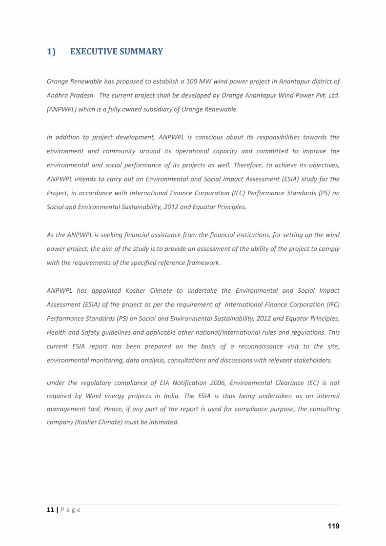
Orange Renewable has proposed to establish a 100 MW wind power project in Anantapur district of
Andhra Pradesh. The current project shall be developed by Orange Anantapur Wind Power Pvt. Ltd.
(ANPWPL) which is a fully owned subsidiary of Orange Renewable.
In addition to project development, ANPWPL is conscious about its responsibilities towards the
environment and community around its operational capacity and committed to improve the
environmental and social performance of its projects as well. Therefore, to achieve its objectives,
ANPWPL intends to carry out an Environmental and Social Impact Assessment (ESIA) study for the
Project, in accordance with International Finance Corporation (IFC) Performance Standards (PS) on
Social and Environmental Sustainability, 2012 and Equator Principles.
As the ANPWPL is seeking financial assistance from the financial institutions, for setting up the wind
power project, the aim of the study is to provide an assessment of the ability of the project to comply
with the requirements of the specified reference framework.
ANPWPL has appointed Kosher Climate to undertake the Environmental and Social Impact
Assessment (ESIA) of the project as per the requirement of International Finance Corporation (IFC)
Performance Standards (PS) on Social and Environmental Sustainability, 2012 and Equator Principles,
Health and Safety guidelines and applicable other national/international rules and regulations. This
current ESIA report has been prepared on the basis of a reconnaissance visit to the site,
environmental monitoring, data analysis, consultations and discussions with relevant stakeholders.
Under the regulatory compliance of EIA Notification 2006, Environmental Clearance (EC) is not
required by Wind energy projects in India. The ESIA is thus being undertaken as an internal
management tool. Hence, if any part of the report is used for compliance purpose, the consulting
company (Kosher Climate) must be intimated.
119
12 | P a g e
2) INTRODUCTION
2.1 Project Brief
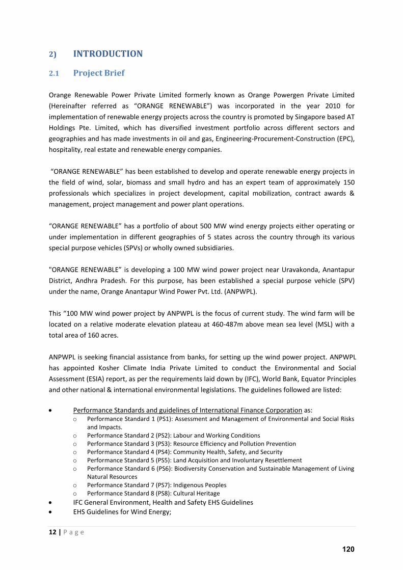
Orange Renewable Power Private Limited formerly known as Orange Powergen Private Limited
(Hereinafter efe ed as O‘ANGE ‘ENEWABLE was incorporated in the year 2010 for
implementation of renewable energy projects across the country is promoted by Singapore based AT
Holdings Pte. Limited, which has diversified investment portfolio across different sectors and
geographies and has made investments in oil and gas, Engineering-Procurement-Construction (EPC),
hospitality, real estate and renewable energy companies.
O‘ANGE ‘ENEWABLE has been established to develop and operate renewable energy projects in
the field of wind, solar, biomass and small hydro and has an expert team of approximately 150
professionals which specializes in project development, capital mobilization, contract awards &
management, project management and power plant operations.
O‘ANGE ‘ENEWABLE has a portfolio of about 500 MW wind energy projects either operating or
under implementation in different geographies of 5 states across the country through its various
special purpose vehicles (SPVs) or wholly owned subsidiaries.
"O‘ANGE ‘ENEWABLE is developing a 100 MW wind power project near Uravakonda, Anantapur
District, Andhra Pradesh. For this purpose, has been established a special purpose vehicle (SPV)
under the name, Orange Anantapur Wind Power Pvt. Ltd. (ANPWPL).
This MW i d po e p oje t ANPWPL is the fo us of u e t stud . The wind farm will be
located on a relative moderate elevation plateau at 460-487m above mean sea level (MSL) with a
total area of 160 acres.
ANPWPL is seeking financial assistance from banks, for setting up the wind power project. ANPWPL
has appointed Kosher Climate India Private Limited to conduct the Environmental and Social
Assessment (ESIA) report, as per the requirements laid down by (IFC), World Bank, Equator Principles
and other national & international environmental legislations. The guidelines followed are listed:
Performance Standards and guidelines of International Finance Corporation as: o Performance Standard 1 (PS1): Assessment and Management of Environmental and Social Risks
and Impacts.
o Performance Standard 2 (PS2): Labour and Working Conditions
o Performance Standard 3 (PS3): Resource Efficiency and Pollution Prevention
o Performance Standard 4 (PS4): Community Health, Safety, and Security
o Performance Standard 5 (PS5): Land Acquisition and Involuntary Resettlement
o Performance Standard 6 (PS6): Biodiversity Conservation and Sustainable Management of Living
Natural Resources
o Performance Standard 7 (PS7): Indigenous Peoples
o Performance Standard 8 (PS8): Cultural Heritage
IFC General Environment, Health and Safety EHS Guidelines
EHS Guidelines for Wind Energy;
120
13 | P a g e
EHS Guidelines for Power Transmission and Distribution
Equator Principles, June 2013
Applicable National Regulatory Requirements
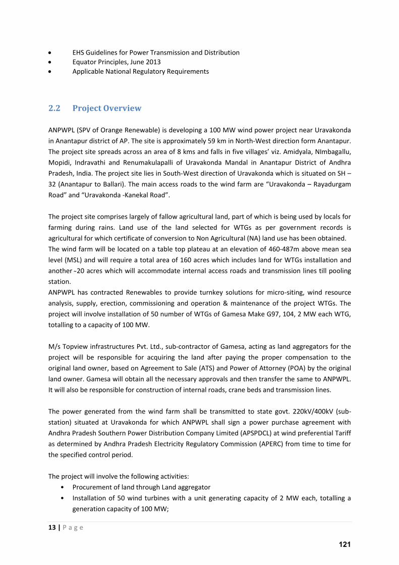
2.2 Project Overview
ANPWPL (SPV of Orange Renewable) is developing a 100 MW wind power project near Uravakonda
in Anantapur district of AP. The site is approximately 59 km in North-West direction form Anantapur.
The p oje t site sp eads a oss a a ea of k s a d falls i fi e illages iz. A id ala, NI agallu,
Mopidi, Indravathi and Renumakulapalli of Uravakonda Mandal in Anantapur District of Andhra
Pradesh, India. The project site lies in South-West direction of Uravakonda which is situated on SH –
32 (Anantapur to Ballari). The main access roads to the wind farm are Uravakonda – Rayadurgam
Road and Uravakonda -Kanekal Road .
The project site comprises largely of fallow agricultural land, part of which is being used by locals for
farming during rains. Land use of the land selected for WTGs as per government records is
agricultural for which certificate of conversion to Non Agricultural (NA) land use has been obtained.
The wind farm will be located on a table top plateau at an elevation of 460-487m above mean sea
level (MSL) and will require a total area of 160 acres which includes land for WTGs installation and
another 20 acres which will accommodate internal access roads and transmission lines till pooling
station.
ANPWPL has contracted Renewables to provide turnkey solutions for micro-siting, wind resource
analysis, supply, erection, commissioning and operation & maintenance of the project WTGs. The
project will involve installation of 50 number of WTGs of Gamesa Make G97, 104, 2 MW each WTG,
totalling to a capacity of 100 MW.
M/s Topview infrastructures Pvt. Ltd., sub-contractor of Gamesa, acting as land aggregators for the
project will be responsible for acquiring the land after paying the proper compensation to the
original land owner, based on Agreement to Sale (ATS) and Power of Attorney (POA) by the original
land owner. Gamesa will obtain all the necessary approvals and then transfer the same to ANPWPL.
It will also be responsible for construction of internal roads, crane beds and transmission lines.
The power generated from the wind farm shall be transmitted to state govt. 220kV/400kV (sub-
station) situated at Uravakonda for which ANPWPL shall sign a power purchase agreement with
Andhra Pradesh Southern Power Distribution Company Limited (APSPDCL) at wind preferential Tariff
as determined by Andhra Pradesh Electricity Regulatory Commission (APERC) from time to time for
the specified control period.
The project will involve the following activities:
• Procurement of land through Land aggregator
• Installation of 50 wind turbines with a unit generating capacity of 2 MW each, totalling a
generation capacity of 100 MW;
121
14 | P a g e
• Electrical connection will require feeder underground cable from the turbines, to the
distribution transformers and a connection to the substation.
• Construction of access roads and internal roads
• Power evacuation at 220/400 kV Uravakonda substation
2.3 Implementation Progress
The status of project implementation as on November 30, 2015 is as follows:
Wind Resource Assessment completed;
Micro-siting has been completed;
WTG land acquisition completed for 80% locations with demarcations and pathway
finalization in progress;
Soil testing completed for all the site being purchased;
Pooling Substation and zero point storage yard completed;
Approach and internal roads completed to WTG clusters and in some clusters to individual
WTGs;
WTGs Foundations completed at twenty sites
Erection of tower and stringing underway to the PSS (Evacuation);
Site office of ANPWPL established and Project staff mobilization completed
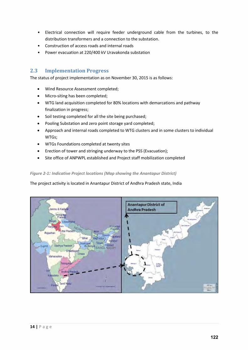
Figure 2-1: Indicative Project locations (Map showing the Anantapur District)
The project activity is located in Anantapur District of Andhra Pradesh state, India
122
15 | P a g e
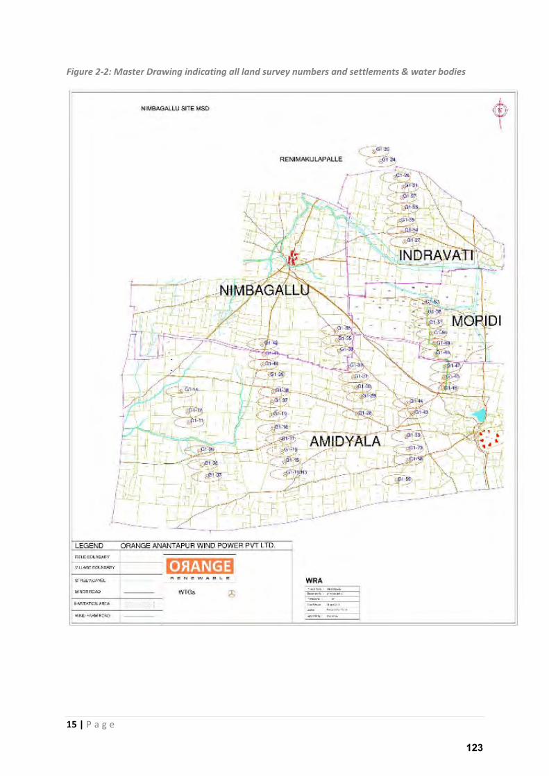
Figure 2-2: Master Drawing indicating all land survey numbers and settlements & water bodies
123
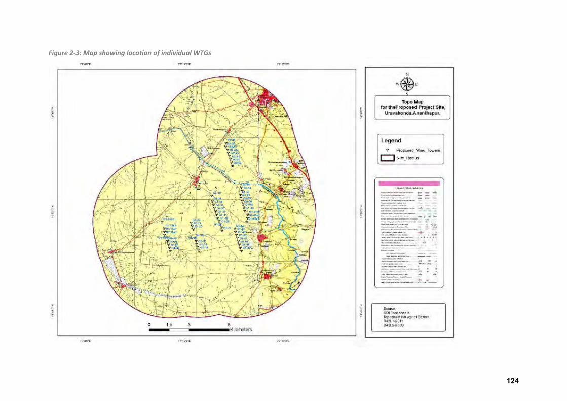
Figure 2-3: Map showing location of individual WTGs
124
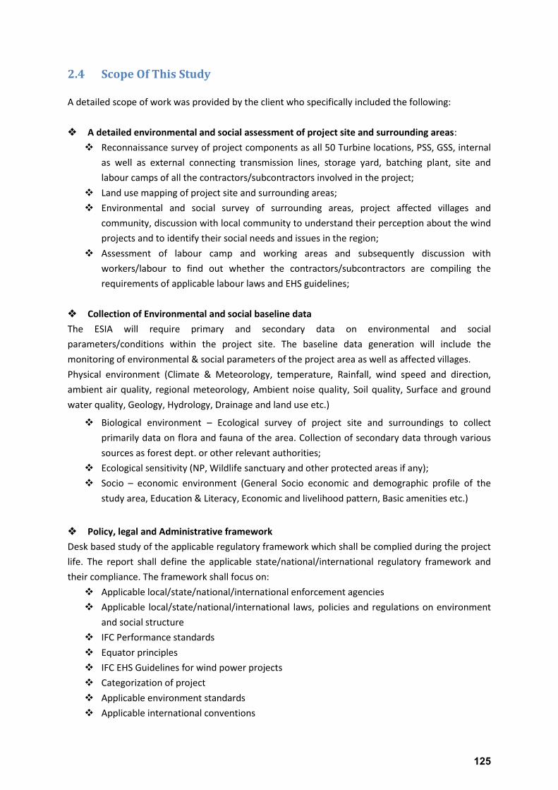
2.4 Scope Of This Study
A detailed scope of work was provided by the client who specifically included the following:
A detailed environmental and social assessment of project site and surrounding areas:
Reconnaissance survey of project components as all 50 Turbine locations, PSS, GSS, internal
as well as external connecting transmission lines, storage yard, batching plant, site and
labour camps of all the contractors/subcontractors involved in the project;
Land use mapping of project site and surrounding areas;
Environmental and social survey of surrounding areas, project affected villages and
community, discussion with local community to understand their perception about the wind
projects and to identify their social needs and issues in the region;
Assessment of labour camp and working areas and subsequently discussion with
workers/labour to find out whether the contractors/subcontractors are compiling the
requirements of applicable labour laws and EHS guidelines;
Collection of Environmental and social baseline data
The ESIA will require primary and secondary data on environmental and social
parameters/conditions within the project site. The baseline data generation will include the
monitoring of environmental & social parameters of the project area as well as affected villages.
Physical environment (Climate & Meteorology, temperature, Rainfall, wind speed and direction,
ambient air quality, regional meteorology, Ambient noise quality, Soil quality, Surface and ground
water quality, Geology, Hydrology, Drainage and land use etc.)
Biological environment – Ecological survey of project site and surroundings to collect
primarily data on flora and fauna of the area. Collection of secondary data through various
sources as forest dept. or other relevant authorities;
Ecological sensitivity (NP, Wildlife sanctuary and other protected areas if any);
Socio – economic environment (General Socio economic and demographic profile of the
study area, Education & Literacy, Economic and livelihood pattern, Basic amenities etc.)
Policy, legal and Administrative framework
Desk based study of the applicable regulatory framework which shall be complied during the project
life. The report shall define the applicable state/national/international regulatory framework and
their compliance. The framework shall focus on:
Applicable local/state/national/international enforcement agencies
Applicable local/state/national/international laws, policies and regulations on environment
and social structure
IFC Performance standards
Equator principles
IFC EHS Guidelines for wind power projects
Categorization of project
Applicable environment standards
Applicable international conventions
125
13 | P a g e
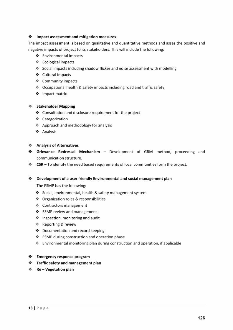
Impact assessment and mitigation measures
The impact assessment is based on qualitative and quantitative methods and asses the positive and
negative impacts of project to its stakeholders. This will include the following:
Environmental impacts
Ecological impacts
Social impacts including shadow flicker and noise assessment with modelling
Cultural Impacts
Community impacts
Occupational health & safety impacts including road and traffic safety
Impact matrix
Stakeholder Mapping
Consultation and disclosure requirement for the project
Categorization
Approach and methodology for analysis
Analysis
Analysis of Alternatives
Grievance Redressal Mechanism – Development of GRM method, proceeding and
communication structure.
CSR – To identify the need based requirements of local communities form the project.
Development of a user friendly Environmental and social management plan
The ESMP has the following:
Social, environmental, health & safety management system
Organization roles & responsibilities
Contractors management
ESMP review and management
Inspection, monitoring and audit
Reporting & review
Documentation and record keeping
ESMP during construction and operation phase
Environmental monitoring plan during construction and operation, if applicable
Emergency response program
Traffic safety and management plan
Re – Vegetation plan
126
14 | P a g e
2.5 Purpose of the Study
The current study is embarked to assess the Environmental & Social impacts of the project activity
based on the requirements of the International Finance Corporation (IFC) Guidelines. Apart from IFC
guideli es the stud also assesses the p oje t s compliance to all the guidelines as listed in the
chapter 4 of this report. Appropriate mitigation measures and environmental and social
management plans have been suggested to restrain and reduce all impacts identified during the
Assessment Study.
2.6 Objective of the Study
The study has been undertaken to fulfil the objectives as listed below:
To describe the proposed project and associated works together with the requirements
for carrying out the proposed developments;
To define the elements of existing baseline conditions prevailing in the study area;
to identify and describe elements of community and environment likely to be affected by
the proposed developments and/or likely to cause adverse impacts to the proposed
project;
to identify the aspects of project which may have impact on sensitive receptors and
quantify the same with reference to the significance of impacts;
to identify and quantify any potential losses or damage to flora, fauna and natural
habitats;
to identify any negative impacts on sites of cultural heritage and to propose measures to
mitigate these impacts;
to identify the impacts and propose the provision of mitigation measures so as to
minimize pollution, environmental disturbance and nuisance during construction and
operation of the developments arising from the Study;
to design and specify environmental monitoring and audit requirements, if necessary, to
ensure the implementation and the effectiveness of the environmental protection and
pollution control measures adopted;
To document the stakeholder consultation during the study;
To develop plans for the management and monitoring of impacts, including plans for on-
going stakeholder engagement;
2.7 Limitations of the Study
The ESIA study is a valiant effort to address key issues pertaining to the project including surface
water, hydrogeology, ecology, air quality, noise quality and socio-economics aspects. The study has
been conducted based on standard approaches and best suited methodology which can be
practically implemented. These approach and methodology are scientifically driven; however, the
end analysis is heavily dependent on the limitation of data/information available and
implementation status of the project. Below a few limitations in the study are highlighted:
127
15 | P a g e
Tentatively identified site tend to change in case of any technical difficulty which cannot be
assessed or included in the report.
The progress at the site was limited and evacuation arrangements were not fully planned;
hence the reconnaissance survey could not cover the transmission lines.
Only select land sellers could be consulted, which may not be an ideal sample to assess or
representative of others.
Social Impact Assessment was limited to 50-100 families per village and Sarpanch/secretary
of the Village. A number of Government officials could not be reached given the schedule
and their non-availability.
Consultation with subcontractors was limited to the ones engaged. A number of sub-
contractors will be engaged as the implementation progresses.
ESIA is an iterative process and the Proponent must adopt a process of continual improvement in
managing and/or mitigating adverse environmental impacts arising from the project. The EMP will
be used as a basis of environmental management and should be improved and refined periodically.
2.8 Approach and Methodology
This Section summarises the key stages of the ESIA process undertaken by Consultant. As such, it
presents the approach that has been adopted for the execution of this ESIA and defines the
methodology that has been used for the collection of baseline data and mainly for the assessment of
impacts.
The diagrammatic presentation of approach and methodology applied for the execution of the
impact assessment study is as provided:
128
16 | P a g e
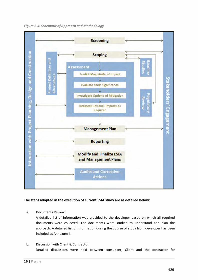
Figure 2-4: Schematic of Approach and Methodology
The steps adopted in the execution of current ESIA study are as detailed below:
a. Documents Review:
A detailed list of information was provided to the developer based on which all required
documents were collected. The documents were studied to understand and plan the
approach. A detailed list of information during the course of study from developer has been
included as Annexure I.
b. Discussion with Client & Contractor:
Detailed discussions were held between consultant, Client and the contractor for
129
17 | P a g e
understanding the progress and plan of the project activity.
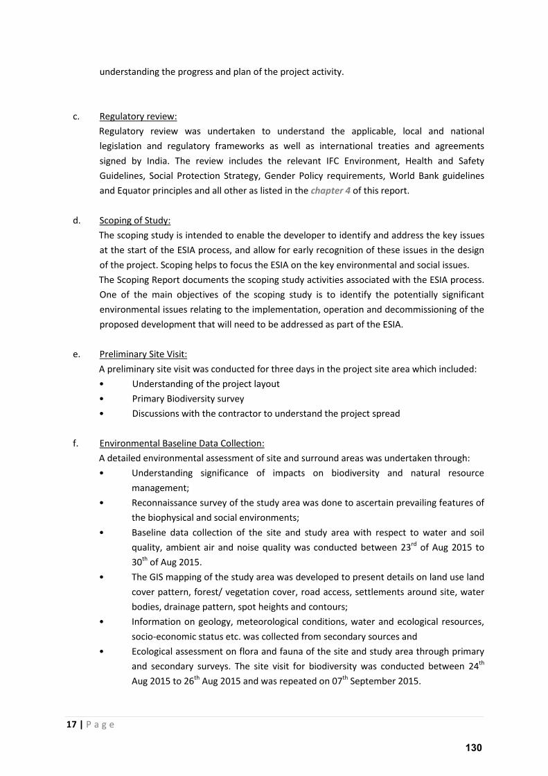
c. Regulatory review:
Regulatory review was undertaken to understand the applicable, local and national
legislation and regulatory frameworks as well as international treaties and agreements
signed by India. The review includes the relevant IFC Environment, Health and Safety
Guidelines, Social Protection Strategy, Gender Policy requirements, World Bank guidelines
and Equator principles and all other as listed in the chapter 4 of this report.
d. Scoping of Study:
The scoping study is intended to enable the developer to identify and address the key issues
at the start of the ESIA process, and allow for early recognition of these issues in the design
of the project. Scoping helps to focus the ESIA on the key environmental and social issues.
The Scoping Report documents the scoping study activities associated with the ESIA process.
One of the main objectives of the scoping study is to identify the potentially significant
environmental issues relating to the implementation, operation and decommissioning of the
proposed development that will need to be addressed as part of the ESIA.
e. Preliminary Site Visit:
A preliminary site visit was conducted for three days in the project site area which included:
• Understanding of the project layout
• Primary Biodiversity survey
• Discussions with the contractor to understand the project spread
f. Environmental Baseline Data Collection:
A detailed environmental assessment of site and surround areas was undertaken through:
• Understanding significance of impacts on biodiversity and natural resource
management;
• Reconnaissance survey of the study area was done to ascertain prevailing features of
the biophysical and social environments;
• Baseline data collection of the site and study area with respect to water and soil
quality, ambient air and noise quality was conducted between 23rd of Aug 2015 to
30th of Aug 2015.
• The GIS mapping of the study area was developed to present details on land use land
cover pattern, forest/ vegetation cover, road access, settlements around site, water
bodies, drainage pattern, spot heights and contours;
• Information on geology, meteorological conditions, water and ecological resources,
socio-economic status etc. was collected from secondary sources and
• Ecological assessment on flora and fauna of the site and study area through primary
and secondary surveys. The site visit for biodiversity was conducted between 24th
Aug 2015 to 26th Aug 2015 and was repeated on 07th September 2015.
130
18 | P a g e
g. Social Consultations:
A detailed social assessment of site and surround areas was undertaken through:
• Reconnaissance surveys to understand site specific issues was conducted between,
24th Aug 2015 to 26th Aug 2015 it included understanding the local conditions and
factoring of all possible areas which the project will effect or be effected in-turn.
• Further, detailed social survey was conducted from 02nd of Sep 2015 to 09th of Sep
2015 which covered all the identified areas under preliminary survey.
• Government policies and engagement of communities was understood.
• Availability of human resource and possible impact of the local man power.
• Impacts pertaining to land aggregation on marginalized communities, local
population and heritage sites.
• Impact of possible HSE issues related to construction, erection and operation of the
project activity.
• Discussions with the local community and identification any key issues;
• Collation of secondary information on social aspect of the site, supplemented by
consultations with the local communities to understand community perception with
regard to the project and its activities.
The details of stakeholde s appi g a d o sultatio is p o ided under the chapter 6 of this
report.
h. Impact Assessment:
Based on the result of the baseline survey the assessment of potential impacts of the project
on the characteristics of environmental and social conditions is identifies.
The range of potential impacts and extent of their severity on environment, ecology, socio-
economic resources, demographics, livelihoods, as well as access to infrastructure issues is
drawn based on the actual and foreseeable activities. Mitigation measures for the identified
impacts are also presented in this part of the study for preparation of Environment and
Social Management Plan.
i. Preparation of Environment and Social Management Plan:
An Environment and Social Management Plan has been developed based on the outcome of
the impact assessment and suggested mitigation measures. These measures will be adopted
by the project proponent to implement during construction and operation of the project
activity.
2.9 Agencies Contacted
The Study involved interaction with a number of individual and organizations for collection of
primary and secondary information pertaining to the site area. These Agencies were either
contacted through meeting, telephonic conversation or written communications.
Survey of India in Bangalore;
Divisional Forest Office, Anantapur;
India Meteorological Department, Meteorological Centre, Bangalore;
131
19 | P a g e
Land and Revenue Department, Anantapur;
Directorate of Census Operations in Bangalore;
Local Panchayats, Sarpanchs and Village Secretary;
Nagaraj, local co-ordinator and Land Aggregator;
Accion Fraterna Ecology Centre;
Sri Krishnadevaraya University, Anantapur;
2.10 Report Structure
The remaining sections of the report include the following:
Section 3: Description of Project;
Section 4: Policy, Legal and Administrative Framework;
Section 5: Analysis of Alternatives;
Section 6: Stakeholder Mapping;
Section 7: Description of Environment (Physical, Metrological, Biological Environment and
Socio-Economic baseline);
Section 8: Anticipated Impact Assessment and Mitigation Measures;
Section 9: Environmental & Social Management Plans
Section 10: Grievance Redressal Mechanism
Section 11: Corporate Social Responsibility (CSR) Plan
Section 12: Impact Summary, Conclusion and Recommendation
Section 13: Annexures
Annexes to the report include the following:
Annexure I: List of Documents Reviewed and collected from ANPWPL
Annexure II: List of Land Owners (Finalized till December 2015)
Annexure III: Noise Modelling (ISO 9613-2 General) Noise Sensitive Receptor
Annexure IV: Shadow Flicker Analysis for Individual Shdaow Receptor
Annexure V: Sample Format Used for Social Consultation- Local Community
Annexure VI: Sample of Format Used for Social Consultation- Village Head
Annexure VII: Photo-documentation of the study area & WTG Profiling
3) PROJECT DESCRIPTION
3.1 Overview:
The following chapter provides details of project and a complete overview of the proposed project
plan in terms of technical details, designs and dimensions. The technical details have been
presented based on the information project by ANPWPL. In due course of implementation, there
may be ground challenges which may contribute to slightly alteration, which ideally should have any
132
20 | P a g e
significant impact on the outcome of this report. The project is being developed by Gamesa on
Turnkey basis as per the agreement with ANPWPL.
A typical wind power project comprises of the following components:
• Wind turbines mounted on towers,
• An electrical collection system, and
• Transmission /interconnection facilities.
Besides these the associated facilities may include access roads, Operation and Maintenance
facilities, and Meteorological tower/s.
The power generated from the project will be evacuated into the Southern Grid at Uravakonda
Substation. A Power Purchase Agreement (PPA) is to be signed with the APDCL for sale of power
generated from the project activity.
The Uravakonda substation (220/400kV) is located in Uravakonda Mandal which is approximately 8.0
km awa f o the p oje t s pooli g su statio / kV at Nimbagallu Village. The power will be
evacuated via a 220KV Moose DC line.
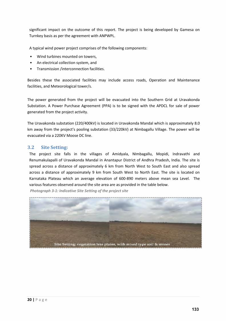
3.2 Site Setting:
The project site falls in the villages of Amidyala, NImbagallu, Mopidi, Indravathi and
Renumakulapalli of Uravakonda Mandal in Anantapur District of Andhra Pradesh, India. The site is
spread across a distance of approximately 6 km from North West to South East and also spread
across a distance of approximately 9 km from South West to North East. The site is located on
Karnataka Plateau which an average elevation of 600-890 meters above mean sea Level. The
various features observed around the site area are as provided in the table below.
Photograph 3-1: Indicative Site Setting of the project site
133
21 | P a g e
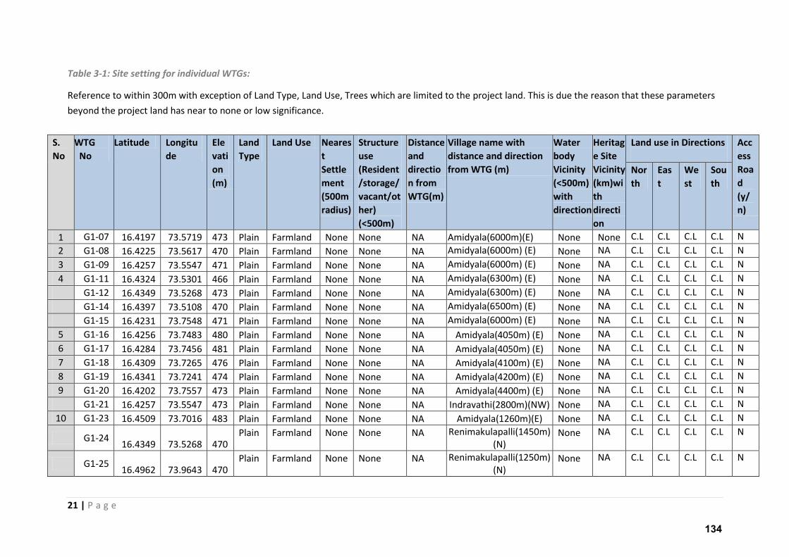
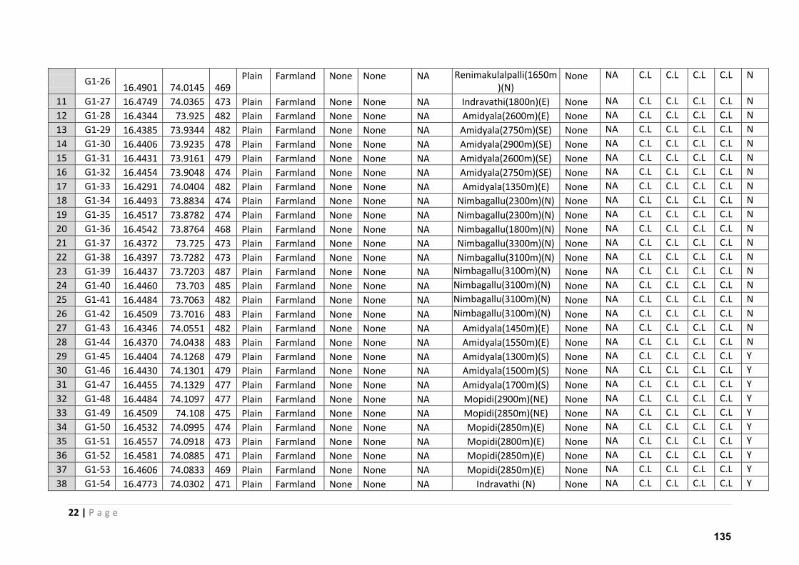
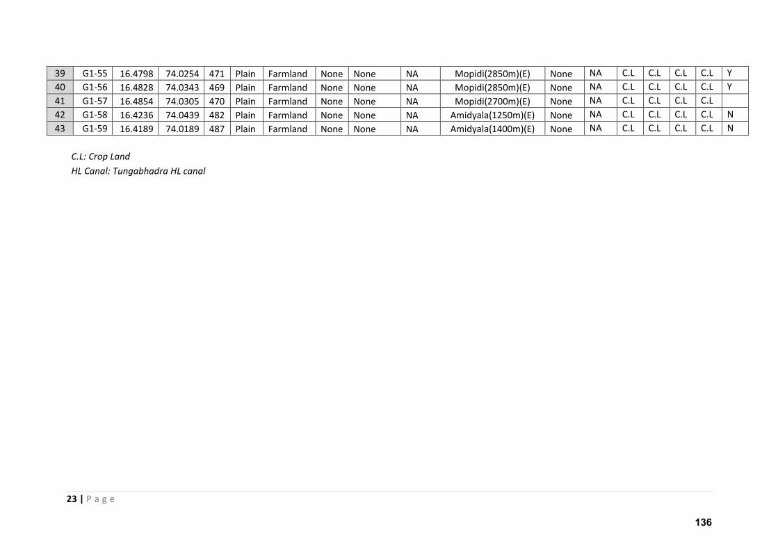
Table 3-1: Site setting for individual WTGs:
Reference to within 300m with exception of Land Type, Land Use, Trees which are limited to the project land. This is due the reason that these parameters
beyond the project land has near to none or low significance.
S.
No
WTG
No
Latitude Longitu
de
Ele
vati
on
(m)
Land
Type
Land Use Neares
t
Settle
ment
(500m
radius)
Structure
use
(Resident
/storage/
vacant/ot
her)
(<500m)
Distance
and
directio
n from
WTG(m)
Village name with
distance and direction
from WTG (m)
Water
body
Vicinity
(<500m)
with
direction
Heritag
e Site
Vicinity
(km)wi
th
directi
on
Land use in Directions
Acc
ess
Roa
d
(y/
n)
Nor
th
Eas
t
We
st
Sou
th
1 G1-07 16.4197 73.5719 473 Plain Farmland None None NA Amidyala(6000m)(E) None None C.L C.L C.L C.L N
2 G1-08 16.4225 73.5617 470 Plain Farmland None None NA Amidyala(6000m) (E) None NA C.L C.L C.L C.L N
3 G1-09 16.4257 73.5547 471 Plain Farmland None None NA Amidyala(6000m) (E) None NA C.L C.L C.L C.L N
4 G1-11 16.4324 73.5301 466 Plain Farmland None None NA Amidyala(6300m) (E) None NA C.L C.L C.L C.L N
G1-12 16.4349 73.5268 473 Plain Farmland None None NA Amidyala(6300m) (E) None NA C.L C.L C.L C.L N
G1-14 16.4397 73.5108 470 Plain Farmland None None NA Amidyala(6500m) (E) None NA C.L C.L C.L C.L N
G1-15 16.4231 73.7548 471 Plain Farmland None None NA Amidyala(6000m) (E) None NA C.L C.L C.L C.L N
5 G1-16 16.4256 73.7483 480 Plain Farmland None None NA Amidyala(4050m) (E) None NA C.L C.L C.L C.L N
6 G1-17 16.4284 73.7456 481 Plain Farmland None None NA Amidyala(4050m) (E) None NA C.L C.L C.L C.L N
7 G1-18 16.4309 73.7265 476 Plain Farmland None None NA Amidyala(4100m) (E) None NA C.L C.L C.L C.L N
8 G1-19 16.4341 73.7241 474 Plain Farmland None None NA Amidyala(4200m) (E) None NA C.L C.L C.L C.L N
9 G1-20 16.4202 73.7557 473 Plain Farmland None None NA Amidyala(4400m) (E) None NA C.L C.L C.L C.L N
G1-21 16.4257 73.5547 473 Plain Farmland None None NA Indravathi(2800m)(NW) None NA C.L C.L C.L C.L N
10 G1-23 16.4509 73.7016 483 Plain Farmland None None NA Amidyala(1260m)(E) None NA C.L C.L C.L C.L N
G1-24 16.4349 73.5268 470
Plain Farmland None None NA Renimakulapalli(1450m)
(N) None NA C.L C.L C.L C.L N
G1-25 16.4962 73.9643 470
Plain Farmland None None NA Renimakulapalli(1250m)
(N) None NA C.L C.L C.L C.L N
134
22 | P a g e
G1-26 16.4901 74.0145 469
Plain Farmland None None NA Renimakulalpalli(1650m
)(N) None NA C.L C.L C.L C.L N
11 G1-27 16.4749 74.0365 473 Plain Farmland None None NA Indravathi(1800n)(E) None NA C.L C.L C.L C.L N
12 G1-28 16.4344 73.925 482 Plain Farmland None None NA Amidyala(2600m)(E) None NA C.L C.L C.L C.L N
13 G1-29 16.4385 73.9344 482 Plain Farmland None None NA Amidyala(2750m)(SE) None NA C.L C.L C.L C.L N
14 G1-30 16.4406 73.9235 478 Plain Farmland None None NA Amidyala(2900m)(SE) None NA C.L C.L C.L C.L N
15 G1-31 16.4431 73.9161 479 Plain Farmland None None NA Amidyala(2600m)(SE) None NA C.L C.L C.L C.L N
16 G1-32 16.4454 73.9048 474 Plain Farmland None None NA Amidyala(2750m)(SE) None NA C.L C.L C.L C.L N
17 G1-33 16.4291 74.0404 482 Plain Farmland None None NA Amidyala(1350m)(E) None NA C.L C.L C.L C.L N
18 G1-34 16.4493 73.8834 474 Plain Farmland None None NA Nimbagallu(2300m)(N) None NA C.L C.L C.L C.L N
19 G1-35 16.4517 73.8782 474 Plain Farmland None None NA Nimbagallu(2300m)(N) None NA C.L C.L C.L C.L N
20 G1-36 16.4542 73.8764 468 Plain Farmland None None NA Nimbagallu(1800m)(N) None NA C.L C.L C.L C.L N
21 G1-37 16.4372 73.725 473 Plain Farmland None None NA Nimbagallu(3300m)(N) None NA C.L C.L C.L C.L N
22 G1-38 16.4397 73.7282 473 Plain Farmland None None NA Nimbagallu(3100m)(N) None NA C.L C.L C.L C.L N
23 G1-39 16.4437 73.7203 487 Plain Farmland None None NA Nimbagallu(3100m)(N) None NA C.L C.L C.L C.L N
24 G1-40 16.4460 73.703 485 Plain Farmland None None NA Nimbagallu(3100m)(N) None NA C.L C.L C.L C.L N
25 G1-41 16.4484 73.7063 482 Plain Farmland None None NA Nimbagallu(3100m)(N) None NA C.L C.L C.L C.L N
26 G1-42 16.4509 73.7016 483 Plain Farmland None None NA Nimbagallu(3100m)(N) None NA C.L C.L C.L C.L N
27 G1-43 16.4346 74.0551 482 Plain Farmland None None NA Amidyala(1450m)(E) None NA C.L C.L C.L C.L N
28 G1-44 16.4370 74.0438 483 Plain Farmland None None NA Amidyala(1550m)(E) None NA C.L C.L C.L C.L N
29 G1-45 16.4404 74.1268 479 Plain Farmland None None NA Amidyala(1300m)(S) None NA C.L C.L C.L C.L Y
30 G1-46 16.4430 74.1301 479 Plain Farmland None None NA Amidyala(1500m)(S) None NA C.L C.L C.L C.L Y
31 G1-47 16.4455 74.1329 477 Plain Farmland None None NA Amidyala(1700m)(S) None NA C.L C.L C.L C.L Y
32 G1-48 16.4484 74.1097 477 Plain Farmland None None NA Mopidi(2900m)(NE) None NA C.L C.L C.L C.L Y
33 G1-49 16.4509 74.108 475 Plain Farmland None None NA Mopidi(2850m)(NE) None NA C.L C.L C.L C.L Y
34 G1-50 16.4532 74.0995 474 Plain Farmland None None NA Mopidi(2850m)(E) None NA C.L C.L C.L C.L Y
35 G1-51 16.4557 74.0918 473 Plain Farmland None None NA Mopidi(2800m)(E) None NA C.L C.L C.L C.L Y
36 G1-52 16.4581 74.0885 471 Plain Farmland None None NA Mopidi(2850m)(E) None NA C.L C.L C.L C.L Y
37 G1-53 16.4606 74.0833 469 Plain Farmland None None NA Mopidi(2850m)(E) None NA C.L C.L C.L C.L Y
38 G1-54 16.4773 74.0302 471 Plain Farmland None None NA Indravathi (N) None NA C.L C.L C.L C.L Y
135
23 | P a g e
39 G1-55 16.4798 74.0254 471 Plain Farmland None None NA Mopidi(2850m)(E) None NA C.L C.L C.L C.L Y
40 G1-56 16.4828 74.0343 469 Plain Farmland None None NA Mopidi(2850m)(E) None NA C.L C.L C.L C.L Y
41 G1-57 16.4854 74.0305 470 Plain Farmland None None NA Mopidi(2700m)(E) None NA C.L C.L C.L C.L
42 G1-58 16.4236 74.0439 482 Plain Farmland None None NA Amidyala(1250m)(E) None NA C.L C.L C.L C.L N
43 G1-59 16.4189 74.0189 487 Plain Farmland None None NA Amidyala(1400m)(E) None NA C.L C.L C.L C.L N
C.L: Crop Land
HL Canal: Tungabhadra HL canal
136
24 | P a g e
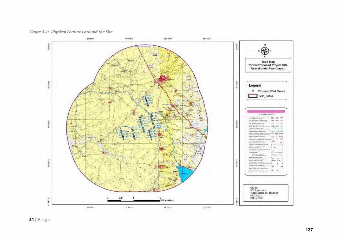
Figure 3-1: Physical Features around the Site
137
25 | P a g e
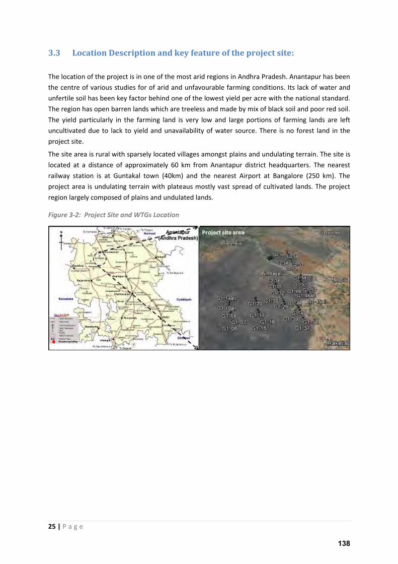
3.3 Location Description and key feature of the project site:
The location of the project is in one of the most arid regions in Andhra Pradesh. Anantapur has been
the centre of various studies for of arid and unfavourable farming conditions. Its lack of water and
unfertile soil has been key factor behind one of the lowest yield per acre with the national standard.
The region has open barren lands which are treeless and made by mix of black soil and poor red soil.
The yield particularly in the farming land is very low and large portions of farming lands are left
uncultivated due to lack to yield and unavailability of water source. There is no forest land in the
project site.
The site area is rural with sparsely located villages amongst plains and undulating terrain. The site is
located at a distance of approximately 60 km from Anantapur district headquarters. The nearest
railway station is at Guntakal town (40km) and the nearest Airport at Bangalore (250 km). The
project area is undulating terrain with plateaus mostly vast spread of cultivated lands. The project
region largely composed of plains and undulated lands.
Figure 3-2: Project Site and WTGs Location
138
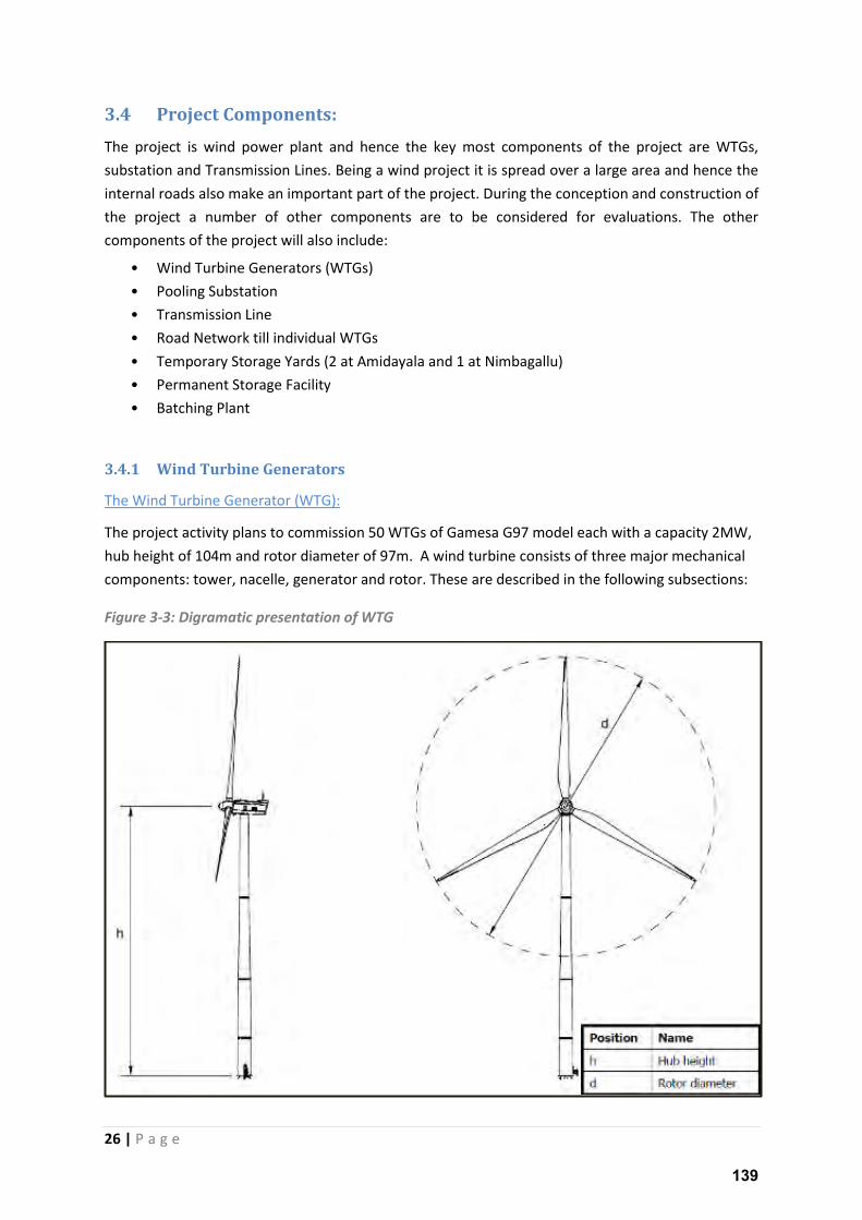
26 | P a g e
3.4 Project Components:
The project is wind power plant and hence the key most components of the project are WTGs,
substation and Transmission Lines. Being a wind project it is spread over a large area and hence the
internal roads also make an important part of the project. During the conception and construction of
the project a number of other components are to be considered for evaluations. The other
components of the project will also include:
• Wind Turbine Generators (WTGs)
• Pooling Substation
• Transmission Line
• Road Network till individual WTGs
• Temporary Storage Yards (2 at Amidayala and 1 at Nimbagallu)
• Permanent Storage Facility
• Batching Plant
3.4.1 Wind Turbine Generators
The Wind Turbine Generator (WTG):
The project activity plans to commission 50 WTGs of Gamesa G97 model each with a capacity 2MW,
hub height of 104m and rotor diameter of 97m. A wind turbine consists of three major mechanical
components: tower, nacelle, generator and rotor. These are described in the following subsections:
Figure 3-3: Digramatic presentation of WTG
139
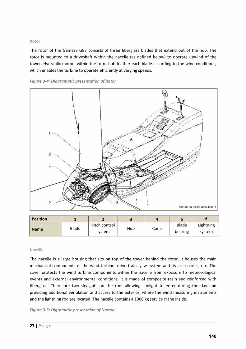
27 | P a g e
Rotor
The rotor of the Gamesa G97 consists of three fiberglass blades that extend out of the hub. The
rotor is mounted to a driveshaft within the nacelle (as defined below) to operate upwind of the
tower. Hydraulic motors within the rotor hub feather each blade according to the wind conditions,
which enables the turbine to operate efficiently at varying speeds.
Figure 3-4: Diagramatic presentation of Rotor
Position 1 2 3 4 5 6
Name Blade Pitch control
system Hub Cone
Blade
bearing
Lightning
system
Nacelle
The nacelle is a large housing that sits on top of the tower behind the rotor. It houses the main
mechanical components of the wind turbine: drive train, yaw system and its accessories, etc. The
cover protects the wind turbine components within the nacelle from exposure to meteorological
events and external environmental conditions. It is made of composite resin and reinforced with
fiberglass. There are two skylights on the roof allowing sunlight to enter during the day and
providing additional ventilation and access to the exterior, where the wind measuring instruments
and the lightning rod are located. The nacelle contains a 1000 kg service crane inside.
Figure 3-5: Digramatic presentaion of Nacelle
140
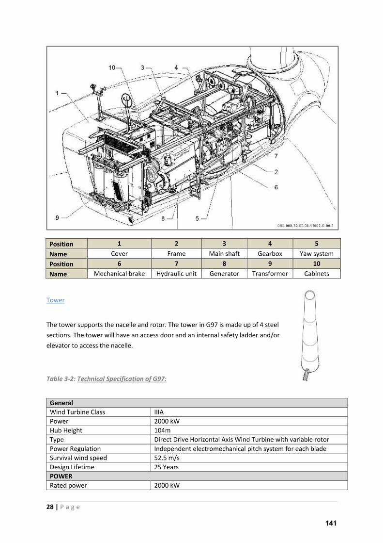
28 | P a g e
Position 1 2 3 4 5
Name Cover Frame Main shaft Gearbox Yaw system
Position 6 7 8 9 10
Name Mechanical brake Hydraulic unit Generator Transformer Cabinets
Tower
The tower supports the nacelle and rotor. The tower in G97 is made up of 4 steel
sections. The tower will have an access door and an internal safety ladder and/or
elevator to access the nacelle.
Table 3-2: Technical Specification of G97:
General
Wind Turbine Class IIIA
Power 2000 kW
Hub Height 104m
Type Direct Drive Horizontal Axis Wind Turbine with variable rotor
Power Regulation Independent electromechanical pitch system for each blade
Survival wind speed 52.5 m/s
Design Lifetime 25 Years
POWER
Rated power 2000 kW
141
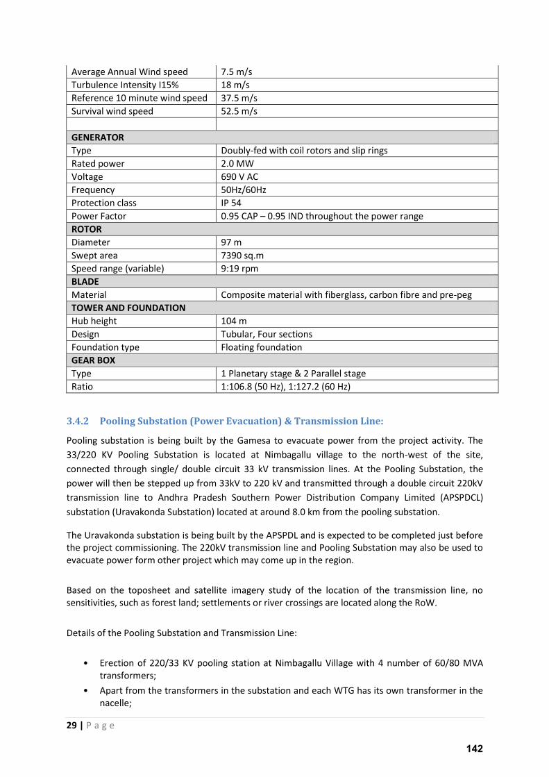
29 | P a g e
Average Annual Wind speed 7.5 m/s
Turbulence Intensity I15% 18 m/s
Reference 10 minute wind speed 37.5 m/s
Survival wind speed 52.5 m/s
GENERATOR
Type Doubly-fed with coil rotors and slip rings
Rated power 2.0 MW
Voltage 690 V AC
Frequency 50Hz/60Hz
Protection class IP 54
Power Factor 0.95 CAP – 0.95 IND throughout the power range
ROTOR
Diameter 97 m
Swept area 7390 sq.m
Speed range (variable) 9:19 rpm
BLADE
Material Composite material with fiberglass, carbon fibre and pre-peg
TOWER AND FOUNDATION
Hub height 104 m
Design Tubular, Four sections
Foundation type Floating foundation
GEAR BOX
Type 1 Planetary stage & 2 Parallel stage
Ratio 1:106.8 (50 Hz), 1:127.2 (60 Hz)
3.4.2 Pooling Substation (Power Evacuation) & Transmission Line:
Pooling substation is being built by the Gamesa to evacuate power from the project activity. The
33/220 KV Pooling Substation is located at Nimbagallu village to the north-west of the site,
connected through single/ double circuit 33 kV transmission lines. At the Pooling Substation, the
power will then be stepped up from 33kV to 220 kV and transmitted through a double circuit 220kV
transmission line to Andhra Pradesh Southern Power Distribution Company Limited (APSPDCL)
substation (Uravakonda Substation) located at around 8.0 km from the pooling substation.
The Uravakonda substation is being built by the APSPDL and is expected to be completed just before
the project commissioning. The 220kV transmission line and Pooling Substation may also be used to
evacuate power form other project which may come up in the region.
Based on the toposheet and satellite imagery study of the location of the transmission line, no
sensitivities, such as forest land; settlements or river crossings are located along the RoW.
Details of the Pooling Substation and Transmission Line:
• Erection of 220/33 KV pooling station at Nimbagallu Village with 4 number of 60/80 MVA
transformers;
• Apart from the transformers in the substation and each WTG has its own transformer in the
nacelle;
142
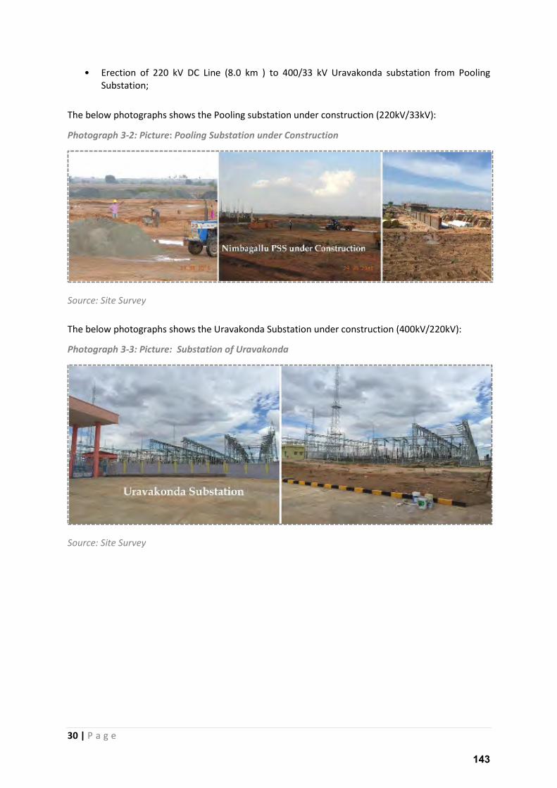
30 | P a g e
• Erection of 220 kV DC Line (8.0 km ) to 400/33 kV Uravakonda substation from Pooling
Substation;
The below photographs shows the Pooling substation under construction (220kV/33kV):
Photograph 3-2: Picture: Pooling Substation under Construction
Source: Site Survey
The below photographs shows the Uravakonda Substation under construction (400kV/220kV):
Photograph 3-3: Picture: Substation of Uravakonda
Source: Site Survey
143
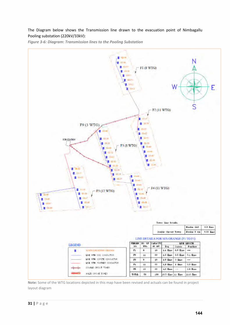
31 | P a g e
The Diagram below shows the Transmission line drawn to the evacuation point of Nimbagallu
Pooling substation (220kV/33kV):
Figure 3-6: Diagram: Transmission lines to the Pooling Substation
Note: Some of the WTG locations depicted in this map have been revised and actuals can be found in project
layout diagram
144
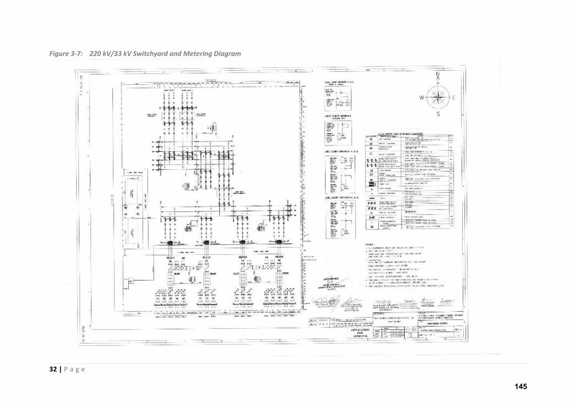
32 | P a g e
Figure 3-7: 220 kV/33 kV Switchyard and Metering Diagram
145

33 | P a g e
3.4.3 Access Road
The project activity is not very far from the existing road networks, however, it is to be noted that
for reach to individual WTGs there is a need to construct internal roads and reinforce the existing
roads to prevent impact from the movement of heavy vehicles. The roads will be planned with a
width of 7m to 12m along the normal course and of 22m along the curves to enable movement of
large wind turbine components. The acceptable supporting or load capacity of the Wind farm access
roads has been agreed at at-least 2kg/sqcm (approx. 0.2 mpa) and the internal access roads will be
at-least 4kg/sqcm (approx. 0.4 mpa), at wearing course level. In total the access road will be spread
over a length of about 11 km and with an approximate width of 7m.
Roads for Access to the Project Site:
The site is accessible via Bellary-Uravakonda-Anantapur NH167 which is principal road connecting
the project site to both Anantapur and Bellary. All the key project equipment is brought to the site
from this road connection. Establishment of access to site will be one of the preliminary activities
that will be undertaken as part of construction process. Two approach roads, with length of 2.5 km
and 3.1 km each, have been proposed for accessing the cluster of WTGs locations. Besides the
approach roads there will be internal roads for access to each turbine location and associated
facilities within the wind farm area.
Figure 3-8: Representation of Material movement to site and Accessibility.
146
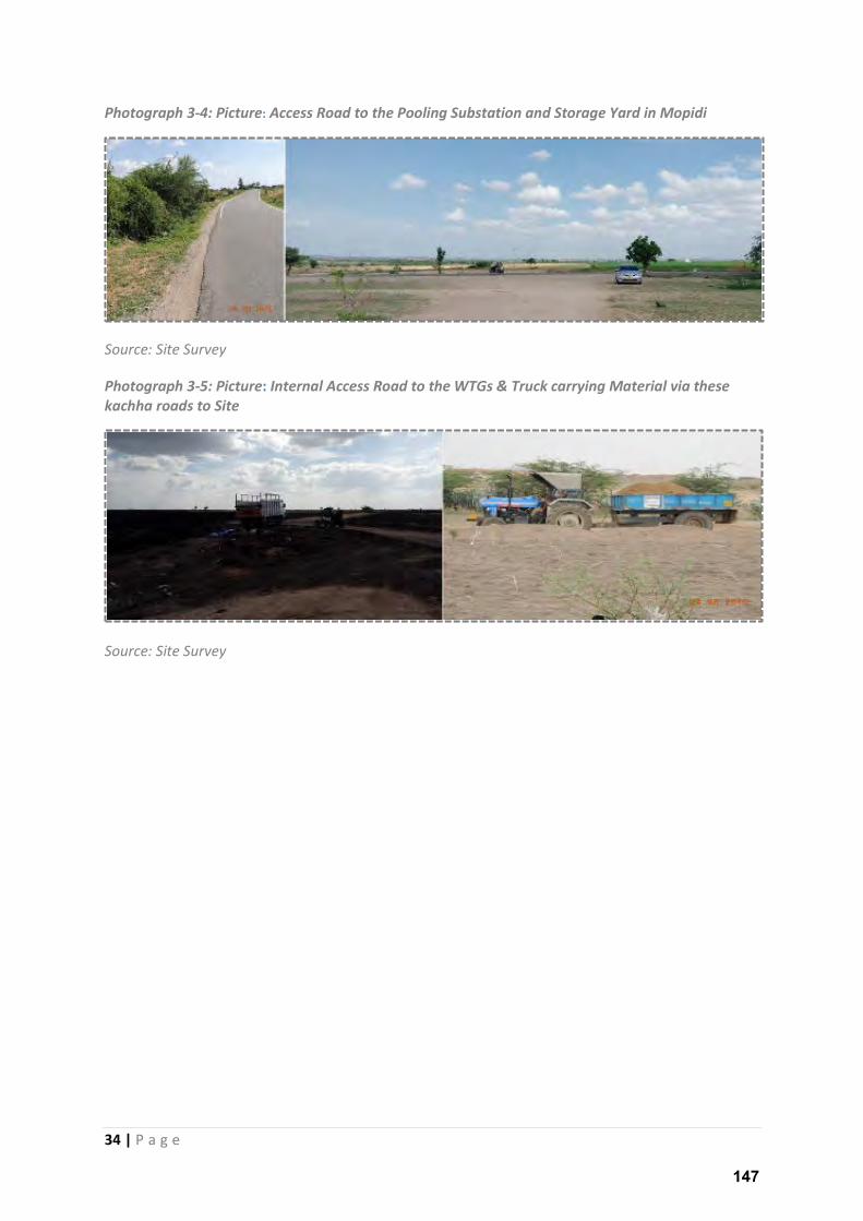
34 | P a g e
Photograph 3-4: Picture: Access Road to the Pooling Substation and Storage Yard in Mopidi
Source: Site Survey
Photograph 3-5: Picture: Internal Access Road to the WTGs & Truck carrying Material via these
kachha roads to Site
Source: Site Survey
147
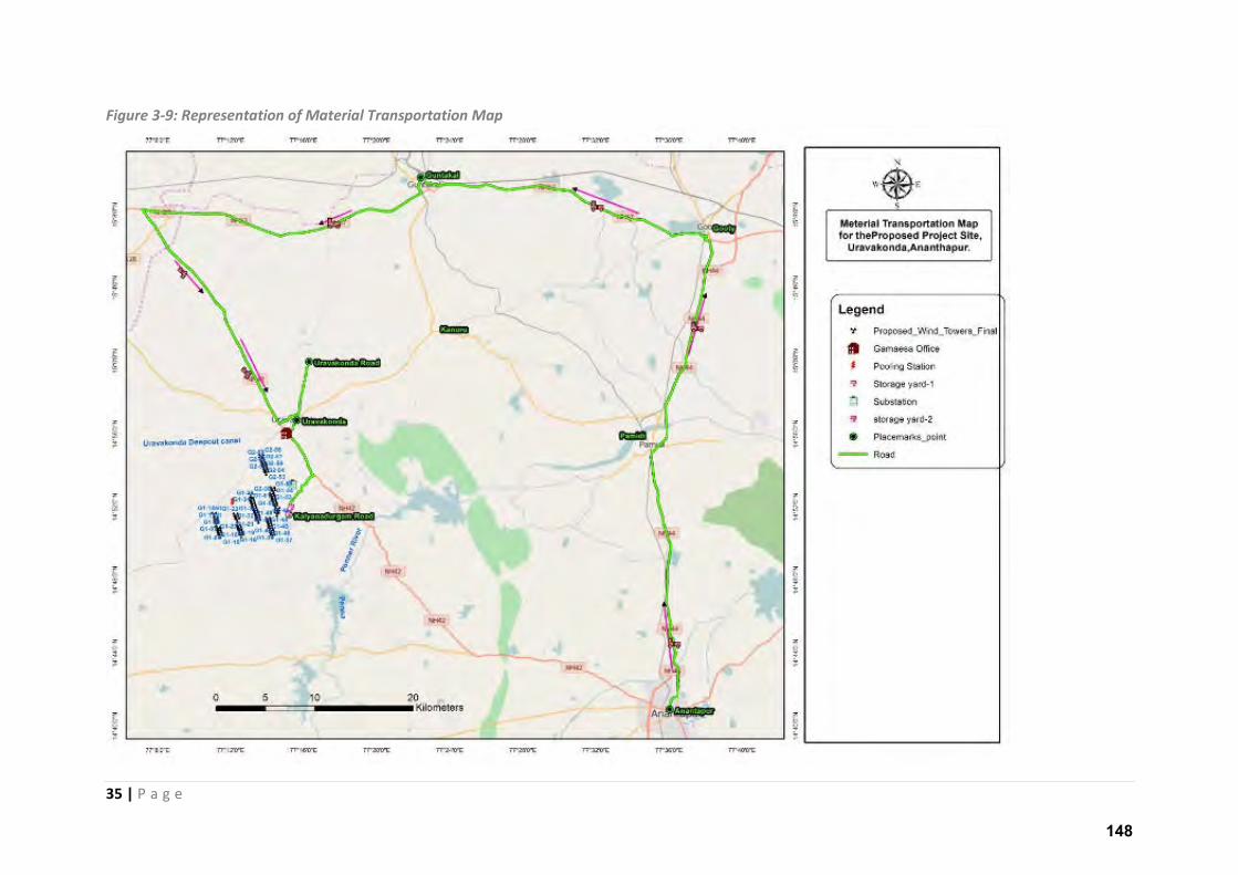
35 | P a g e
Figure 3-9: Representation of Material Transportation Map
148
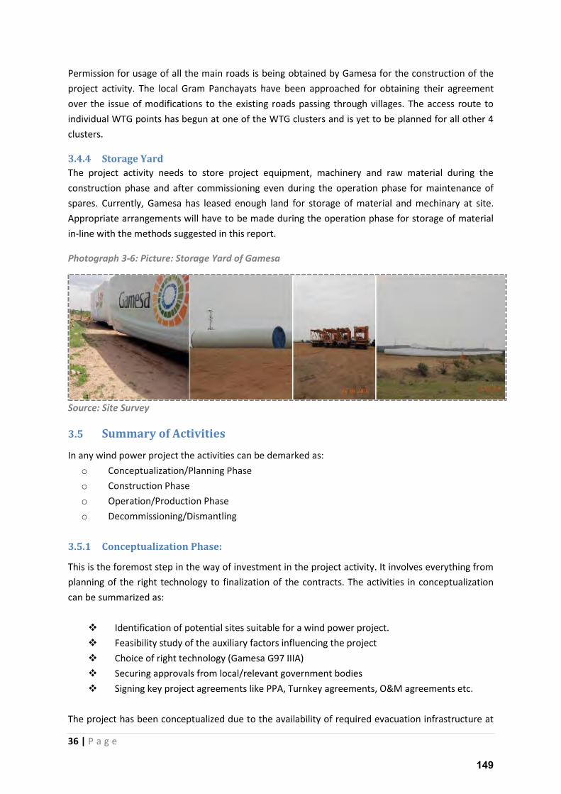
36 | P a g e
Permission for usage of all the main roads is being obtained by Gamesa for the construction of the
project activity. The local Gram Panchayats have been approached for obtaining their agreement
over the issue of modifications to the existing roads passing through villages. The access route to
individual WTG points has begun at one of the WTG clusters and is yet to be planned for all other 4
clusters.
3.4.4 Storage Yard
The project activity needs to store project equipment, machinery and raw material during the
construction phase and after commissioning even during the operation phase for maintenance of
spares. Currently, Gamesa has leased enough land for storage of material and mechinary at site.
Appropriate arrangements will have to be made during the operation phase for storage of material
in-line with the methods suggested in this report.
Photograph 3-6: Picture: Storage Yard of Gamesa
Source: Site Survey
3.5 Summary of Activities
In any wind power project the activities can be demarked as:
o Conceptualization/Planning Phase
o Construction Phase
o Operation/Production Phase
o Decommissioning/Dismantling
3.5.1 Conceptualization Phase:
This is the foremost step in the way of investment in the project activity. It involves everything from
planning of the right technology to finalization of the contracts. The activities in conceptualization
can be summarized as:
Identification of potential sites suitable for a wind power project.
Feasibility study of the auxiliary factors influencing the project
Choice of right technology (Gamesa G97 IIIA)
Securing approvals from local/relevant government bodies
Signing key project agreements like PPA, Turnkey agreements, O&M agreements etc.
The project has been conceptualized due to the availability of required evacuation infrastructure at
149
37 | P a g e
the project site and availability of required land at desired locations.
3.5.2 Construction Phase
The project construction is in progress and the status of the project can be found in section 3.10 of
this chapter. Co st u tio phase is the ost a ti e phase i the p oje t s life le. It a also e termed as the phase with possibly noteworthy impact. The construction activities will have the
following stages:
Development of access roads
Site development activities like site levelling, removal of ground vegetation and any
obstructions in movement of material.
Installation of temporary and/or permanent meteorological towers
Installation of wind turbine and associated facilities
Construction of underground and/or overhead electrical collection lines to connect
turbines to the collection substation
turbine foundations and erection
switch yard structure and equipment foundations including power transformer and
control room cum administration building
Synchronization and commissioning of the WTGs
Security kiosks, collection substation, fencing and drainage etc
3.5.3 Operation & Maintenance
Wind projects require a dedicated Operation and Maintenance (O&M) facility for storing equipment
and supplies required during operation. An O&M agreement has been signed with Gamesa which
entrusts them with responsibility of maintenance and repairs. The Power Purchase Agreement will
be executed before start of the project operation. Gamesa is ISO14001 and OSHA 18001 certified
company with established EHS procedures. The site will be under 24 hours on site monitoring under
the supervision of technically skilled and experienced staff to look after the O&M requirements of
the project activity. A storage yard sufficient stock of tools and spares as well as critical components
will be maintained at the site.
The typical maintenance and repair activity during operation phase involves preventive and
breakdown maintenance of Wind turbines and/or the related equipment in accordance with the
safety management plans and procedures as applicable and/or in accordance with accepted industry
practices.
3.5.4 Decommissioning
Decommissioning activities depend on the proposed subsequent use of the site, but they typically
consist of removal of infrastructure. The life of the project activity is 25 years and depending on the
conditions of equipment and applicable regulation at the e d of p oje t s life le, the de elope will decide whether to decommission the project activity.
150
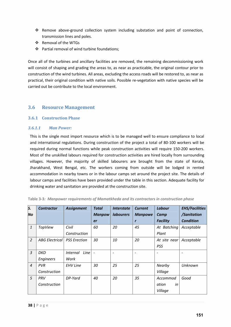
38 | P a g e
Remove above-ground collection system including substation and point of connection,
transmission lines and poles.
Removal of the WTGs
Partial removal of wind turbine foundations;
Once all of the turbines and ancillary facilities are removed, the remaining decommissioning work
will consist of shaping and grading the areas to, as near as practicable, the original contour prior to
construction of the wind turbines. All areas, excluding the access roads will be restored to, as near as
practical, their original condition with native soils. Possible re-vegetation with native species will be
carried out be contribute to the local environment.
3.6 Resource Management
3.6.1 Construction Phase
3.6.1.1 Man Power:
This is the single most import resource which is to be managed well to ensure compliance to local
and international regulations. During construction of the project a total of 80-100 workers will be
required during normal functions while peak construction activities will require 150-200 workers.
Most of the unskilled labours required for construction activities are hired locally from surrounding
villages. However, the majority of skilled labourers are brought from the state of Kerala,
Jharakhand, West Bengal, etc. The workers coming from outside will be lodged in rented
accommodation in nearby towns or in the labour camps set around the project site. The details of
labour camps and facilities have been provided under the table in this section. Adequate facility for
drinking water and sanitation are provided at the construction site.
Table 3-3: Manpower requirements of Mamatkheda and its contractors in construction phase
S.
No
Contractor Assignment Total
Manpow
er
Interstate
labourers
Current
Manpowe
r
Labour
Camp
Facility
EHS/Facilities
/Sanitation
Condition
1 TopView Civil
Construction
60 20 45 At Batching
Plant
Acceptable
2 ABG Electrical PSS Erection 30 10 20 At site near
PSS
Acceptable
3 DKD
Engineers
Internal Line
Work
- - - - -
4 PVR
Construction
EHV Line 30 25 25 Nearby
Village
Unknown
5 PRV
Construction
DP-Yard 40 20 35 Accommod
ation in
Village
Good
151
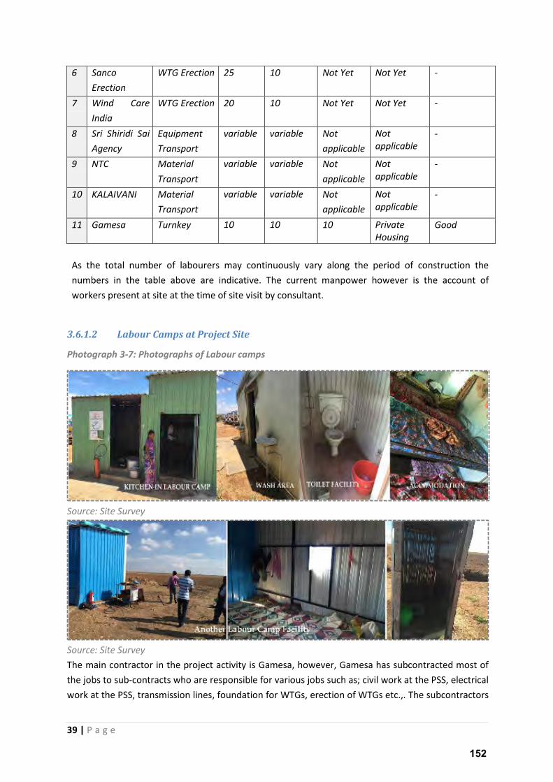
39 | P a g e
6 Sanco
Erection
WTG Erection 25 10 Not Yet Not Yet -
7 Wind Care
India
WTG Erection 20 10 Not Yet Not Yet -
8 Sri Shiridi Sai
Agency
Equipment
Transport
variable variable Not
applicable
Not
applicable
-
9 NTC Material
Transport
variable variable Not
applicable
Not
applicable
-
10 KALAIVANI Material
Transport
variable variable Not
applicable
Not
applicable
-
11 Gamesa Turnkey 10 10 10 Private
Housing
Good
As the total number of labourers may continuously vary along the period of construction the
numbers in the table above are indicative. The current manpower however is the account of
workers present at site at the time of site visit by consultant.
3.6.1.2 Labour Camps at Project Site
Photograph 3-7: Photographs of Labour camps
Source: Site Survey
Source: Site Survey
The main contractor in the project activity is Gamesa, however, Gamesa has subcontracted most of
the jobs to sub-contracts who are responsible for various jobs such as; civil work at the PSS, electrical
work at the PSS, transmission lines, foundation for WTGs, erection of WTGs etc.,. The subcontractors
152
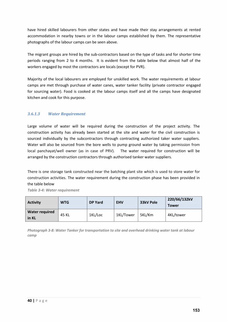
40 | P a g e
have hired skilled labourers from other states and have made their stay arrangements at rented
accommodation in nearby towns or in the labour camps established by them. The representative
photographs of the labour camps can be seen above.
The migrant groups are hired by the sub-contractors based on the type of tasks and for shorter time
periods ranging from 2 to 4 months. It is evident from the table below that almost half of the
workers engaged by most the contractors are locals (except for PVR).
Majority of the local labourers are employed for unskilled work. The water requirements at labour
camps are met through purchase of water canes, water tanker facility (private contractor engaged
for sourcing water). Food is cooked at the labour camps itself and all the camps have designated
kitchen and cook for this purpose.
3.6.1.3 Water Requirement
Large volume of water will be required during the construction of the project activity. The
construction activity has already been started at the site and water for the civil construction is
sourced individually by the subcontractors through contracting authorized taker water suppliers.
Water will also be sourced from the bore wells to pump ground water by taking permission from
local panchayat/well owner (as in case of PRV). The water required for construction will be
arranged by the construction contractors through authorised tanker water suppliers.
There is one storage tank constructed near the batching plant site which is used to store water for
construction activities. The water requirement during the construction phase has been provided in
the table below
Table 3-4: Water requirement
Activity WTG DP Yard EHV 33kV Pole 220/66/132kV
Tower
Water required
in KL 45 KL 1KL/Loc 1KL/Tower 5KL/Km 4KL/tower
Photograph 3-8: Water Tanker for transportation to site and overhead drinking water tank at labour
camp
153
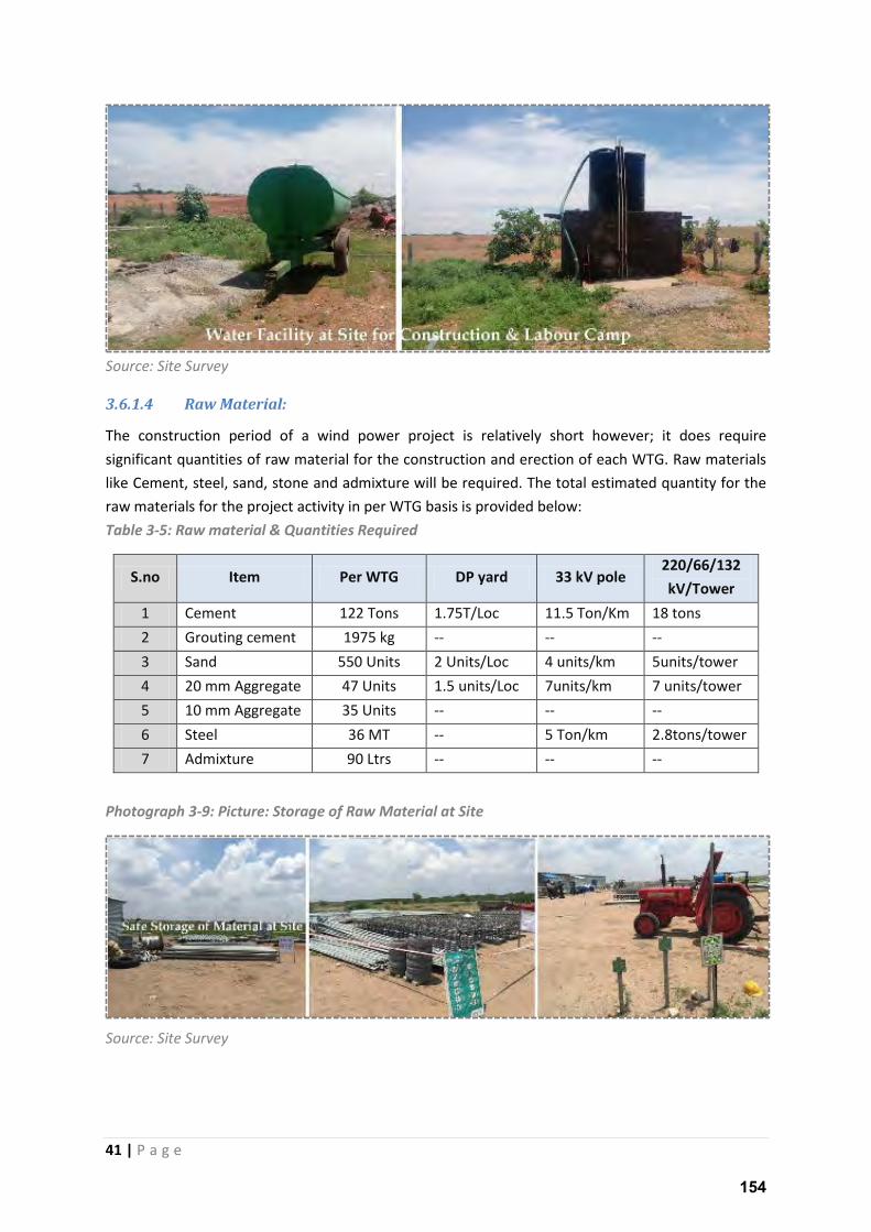
41 | P a g e
Source: Site Survey
3.6.1.4 Raw Material:
The construction period of a wind power project is relatively short however; it does require
significant quantities of raw material for the construction and erection of each WTG. Raw materials
like Cement, steel, sand, stone and admixture will be required. The total estimated quantity for the
raw materials for the project activity in per WTG basis is provided below:
Table 3-5: Raw material & Quantities Required
S.no Item Per WTG DP yard 33 kV pole 220/66/132
kV/Tower
1 Cement 122 Tons 1.75T/Loc 11.5 Ton/Km 18 tons
2 Grouting cement 1975 kg -- -- --
3 Sand 550 Units 2 Units/Loc 4 units/km 5units/tower
4 20 mm Aggregate 47 Units 1.5 units/Loc 7units/km 7 units/tower
5 10 mm Aggregate 35 Units -- -- --
6 Steel 36 MT -- 5 Ton/km 2.8tons/tower
7 Admixture 90 Ltrs -- -- --
Photograph 3-9: Picture: Storage of Raw Material at Site
Source: Site Survey
154
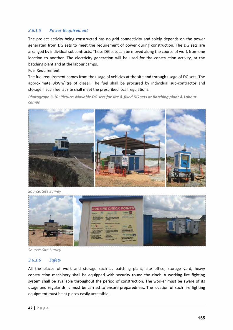
42 | P a g e
3.6.1.5 Power Requirement
The project activity being constructed has no grid connectivity and solely depends on the power
generated from DG sets to meet the requirement of power during construction. The DG sets are
arranged by individual subcontracts. These DG sets can be moved along the course of work from one
location to another. The electricity generation will be used for the construction activity, at the
batching plant and at the labour camps.
Fuel Requirement
The fuel requirement comes from the usage of vehicles at the site and through usage of DG sets. The
approximate 3kWh/litre of diesel. The fuel shall be procured by individual sub-contractor and
storage if such fuel at site shall meet the prescribed local regulations.
Photograph 3-10: Picture: Movable DG sets for site & fixed DG sets at Batching plant & Labour
camps
Source: Site Survey
Source: Site Survey
3.6.1.6 Safety
All the places of work and storage such as batching plant, site office, storage yard, heavy
construction machinery shall be equipped with security round the clock. A working fire fighting
system shall be available throughout the period of construction. The worker must be aware of its
usage and regular drills must be carried to ensure preparedness. The location of such fire fighting
equipment must be at places easily accessible.
155
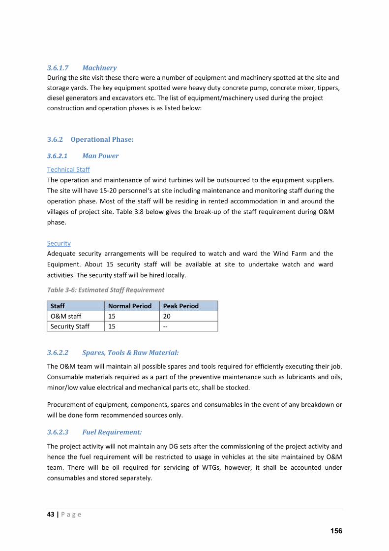
43 | P a g e
3.6.1.7 Machinery
During the site visit these there were a number of equipment and machinery spotted at the site and
storage yards. The key equipment spotted were heavy duty concrete pump, concrete mixer, tippers,
diesel generators and excavators etc. The list of equipment/machinery used during the project
construction and operation phases is as listed below:
3.6.2 Operational Phase:
3.6.2.1 Man Power
Technical Staff
The operation and maintenance of wind turbines will be outsourced to the equipment suppliers.
The site will have 15-20 personnel s at site i ludi g ai te a e a d o ito i g staff du i g the operation phase. Most of the staff will be residing in rented accommodation in and around the
villages of project site. Table 3.8 below gives the break-up of the staff requirement during O&M
phase.
Security Adequate security arrangements will be required to watch and ward the Wind Farm and the
Equipment. About 15 security staff will be available at site to undertake watch and ward
activities. The security staff will be hired locally.
Table 3-6: Estimated Staff Requirement
Staff Normal Period Peak Period
O&M staff 15 20
Security Staff 15 --
3.6.2.2 Spares, Tools & Raw Material:
The O&M team will maintain all possible spares and tools required for efficiently executing their job.
Consumable materials required as a part of the preventive maintenance such as lubricants and oils,
minor/low value electrical and mechanical parts etc, shall be stocked.
Procurement of equipment, components, spares and consumables in the event of any breakdown or
will be done form recommended sources only.
3.6.2.3 Fuel Requirement:
The project activity will not maintain any DG sets after the commissioning of the project activity and
hence the fuel requirement will be restricted to usage in vehicles at the site maintained by O&M
team. There will be oil required for servicing of WTGs, however, it shall be accounted under
consumables and stored separately.
156
44 | P a g e
3.6.2.4 Power Requirement:
As described earlier once the project is commissioned there will no requirement of DG sets at the
sites. Unlike other technologies, a wind power project does not need any axillary power for
operating.
3.7 Benefits of The Project
Unlike conventional power plants a wind power project generates clean energy and has minimal
impact both during its construction and operation. The project draws minimal from the natural
system and generates maximum output. Wind power project come along a number of benefits
to the environment, economy and the local population. The Ministry of Environment and
Forests, Govt. of India has stipulated the following indicators1 for sustainable development in
the interim approval guidelines. These are guidelines for assessing the sustainability of a Clean
Development Mechanism (CDM) project however, as there are set national guidelines for a wind
power project, the current project is being evaluated on the same parameters:
a) Social well-being
b) Economic well-being
c) Environmental well-being
d) Technological well-being
These project activity contributions towards the sustainable development are as follows;
Jobs: The project during the course of construction is expected to create more than 150 jobs. Post
construction the project will continue to engage around 40 personnel. More than 50% of the
manpower used during construction phase will be local workers.
Better price of Land: The project activity offers as much as three folds the market price to the land
seller and also encourages the land sellers in case a job opportunity. This fact has been affirmed
during the social consultation process.
Land Use: A typical WTG will use less than 1 acre permanently and less than 2.5 acres per WTG
during the construction phase. The remainder of the land can be used for a variety of other
productive purposes, including livestock grazing, agriculture etc.
Local Business: The project provides opportunity to the local vehicle leases for long term. It also
helps the villages to get revenue of their houses by renting them at desired price during the
construction phase. Hence, the project can diversify the economies of rural communities, by
creating opportunities during its construction and operation.
1 http://envfor.nic.in/sites/default/files/cc/cdm/criteria.htm
157
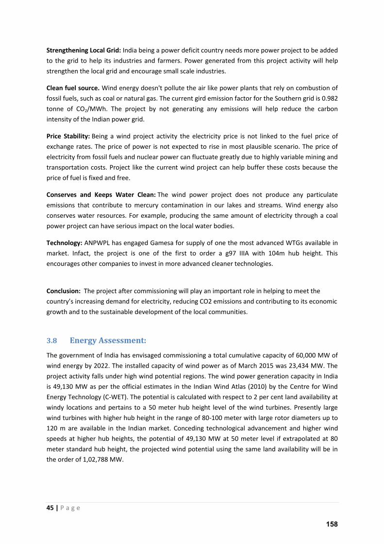
45 | P a g e
Strengthening Local Grid: India being a power deficit country needs more power project to be added
to the grid to help its industries and farmers. Power generated from this project activity will help
strengthen the local grid and encourage small scale industries.
Clean fuel source. Wind energy doesn't pollute the air like power plants that rely on combustion of
fossil fuels, such as coal or natural gas. The current gird emission factor for the Southern grid is 0.982
tonne of CO2/MWh. The project by not generating any emissions will help reduce the carbon
intensity of the Indian power grid.
Price Stability: Being a wind project activity the electricity price is not linked to the fuel price of
exchange rates. The price of power is not expected to rise in most plausible scenario. The price of
electricity from fossil fuels and nuclear power can fluctuate greatly due to highly variable mining and
transportation costs. Project like the current wind project can help buffer these costs because the
price of fuel is fixed and free.
Conserves and Keeps Water Clean: The wind power project does not produce any particulate
emissions that contribute to mercury contamination in our lakes and streams. Wind energy also
conserves water resources. For example, producing the same amount of electricity through a coal
power project can have serious impact on the local water bodies.
Technology: ANPWPL has engaged Gamesa for supply of one the most advanced WTGs available in
market. Infact, the project is one of the first to order a g97 IIIA with 104m hub height. This
encourages other companies to invest in more advanced cleaner technologies.
Conclusion: The project after commissioning will play an important role in helping to meet the
ou t s i easi g de a d fo ele t i it , edu i g CO e issio s a d o t i uti g to its e o o i growth and to the sustainable development of the local communities.
3.8 Energy Assessment:
The government of India has envisaged commissioning a total cumulative capacity of 60,000 MW of
wind energy by 2022. The installed capacity of wind power as of March 2015 was 23,434 MW. The
project activity falls under high wind potential regions. The wind power generation capacity in India
is 49,130 MW as per the official estimates in the Indian Wind Atlas (2010) by the Centre for Wind
Energy Technology (C-WET). The potential is calculated with respect to 2 per cent land availability at
windy locations and pertains to a 50 meter hub height level of the wind turbines. Presently large
wind turbines with higher hub height in the range of 80-100 meter with large rotor diameters up to
120 m are available in the Indian market. Conceding technological advancement and higher wind
speeds at higher hub heights, the potential of 49,130 MW at 50 meter level if extrapolated at 80
meter standard hub height, the projected wind potential using the same land availability will be in
the order of 1,02,788 MW.
158

46 | P a g e
NIWE (earlier C-WET) has assessed India's wind power potential at 100m hub height with scientific
rigor and based on authentic latest available data-sets of wind as well as land geologically spread
across India. The wind potential sites have been classified according to annual mean wind power
density ranging from 200 W/ m2 to 500 W/ m2. As seen in the map below India has good potential
for wind power generation as many areas have more than 200 W/ m2 of wind density.
The below map shows wind density throughout India.
159
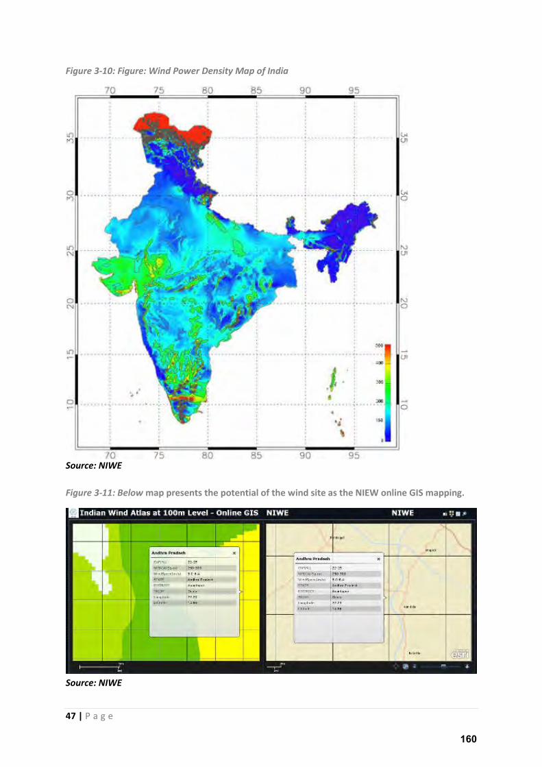
47 | P a g e
Figure 3-10: Figure: Wind Power Density Map of India
Source: NIWE
Figure 3-11: Below map presents the potential of the wind site as the NIEW online GIS mapping.
Source: NIWE
160
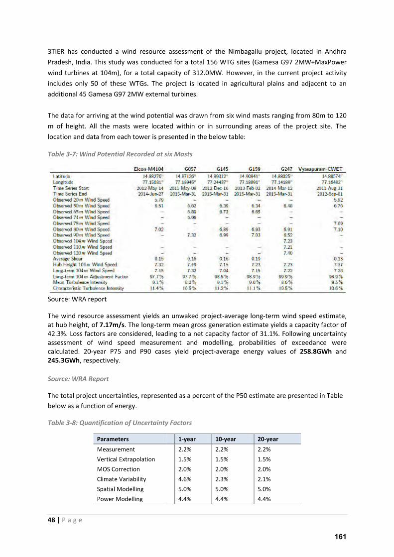
48 | P a g e
3TIER has conducted a wind resource assessment of the Nimbagallu project, located in Andhra
Pradesh, India. This study was conducted for a total 156 WTG sites (Gamesa G97 2MW+MaxPower
wind turbines at 104m), for a total capacity of 312.0MW. However, in the current project activity
includes only 50 of these WTGs. The project is located in agricultural plains and adjacent to an
additional 45 Gamesa G97 2MW external turbines.
The data for arriving at the wind potential was drawn from six wind masts ranging from 80m to 120
m of height. All the masts were located within or in surrounding areas of the project site. The
location and data from each tower is presented in the below table:
Table 3-7: Wind Potential Recorded at six Masts
Source: WRA report
The wind resource assessment yields an unwaked project-average long-term wind speed estimate,
at hub height, of 7.17m/s. The long-term mean gross generation estimate yields a capacity factor of
42.3%. Loss factors are considered, leading to a net capacity factor of 31.1%. Following uncertainty
assessment of wind speed measurement and modelling, probabilities of exceedance were
calculated. 20-year P75 and P90 cases yield project-average energy values of 258.8GWh and
245.3GWh, respectively.
Source: WRA Report
The total project uncertainties, represented as a percent of the P50 estimate are presented in Table
below as a function of energy.
Table 3-8: Quantification of Uncertainty Factors
Parameters
1-year 10-year 20-year
Measurement
2.2% 2.2% 2.2%
Vertical Extrapolation
1.5% 1.5% 1.5%
MOS Correction
2.0% 2.0% 2.0%
Climate Variability
4.6% 2.3% 2.1%
Spatial Modelling
5.0% 5.0% 5.0%
Power Modelling
4.4% 4.4% 4.4%
161
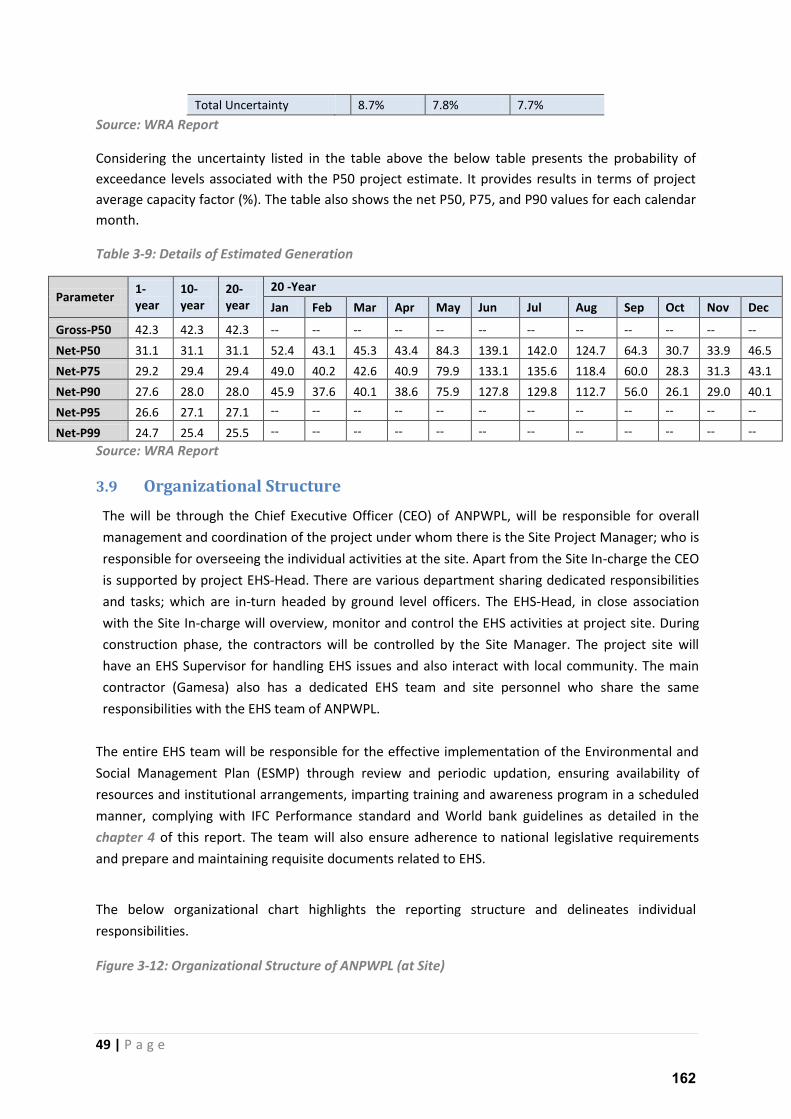
49 | P a g e
Total Uncertainty
8.7% 7.8% 7.7%
Source: WRA Report
Considering the uncertainty listed in the table above the below table presents the probability of
exceedance levels associated with the P50 project estimate. It provides results in terms of project
average capacity factor (%). The table also shows the net P50, P75, and P90 values for each calendar
month.
Table 3-9: Details of Estimated Generation
Parameter 1-
year
10-
year
20-
year
20 -Year
Jan Feb Mar Apr May Jun Jul Aug Sep Oct Nov Dec
Gross-P50 42.3 42.3 42.3 -- -- -- -- -- -- -- -- -- -- -- --
Net-P50 31.1 31.1 31.1 52.4 43.1 45.3 43.4 84.3 139.1 142.0 124.7 64.3 30.7 33.9 46.5
Net-P75 29.2 29.4 29.4 49.0 40.2 42.6 40.9 79.9 133.1 135.6 118.4 60.0 28.3 31.3 43.1
Net-P90 27.6 28.0 28.0 45.9 37.6 40.1 38.6 75.9 127.8 129.8 112.7 56.0 26.1 29.0 40.1
Net-P95 26.6 27.1 27.1 -- -- -- -- -- -- -- -- -- -- -- --
Net-P99 24.7 25.4 25.5 -- -- -- -- -- -- -- -- -- -- -- --
Source: WRA Report
3.9 Organizational Structure
The will be through the Chief Executive Officer (CEO) of ANPWPL, will be responsible for overall
management and coordination of the project under whom there is the Site Project Manager; who is
responsible for overseeing the individual activities at the site. Apart from the Site In-charge the CEO
is supported by project EHS-Head. There are various department sharing dedicated responsibilities
and tasks; which are in-turn headed by ground level officers. The EHS-Head, in close association
with the Site In-charge will overview, monitor and control the EHS activities at project site. During
construction phase, the contractors will be controlled by the Site Manager. The project site will
have an EHS Supervisor for handling EHS issues and also interact with local community. The main
contractor (Gamesa) also has a dedicated EHS team and site personnel who share the same
responsibilities with the EHS team of ANPWPL.
The entire EHS team will be responsible for the effective implementation of the Environmental and
Social Management Plan (ESMP) through review and periodic updation, ensuring availability of
resources and institutional arrangements, imparting training and awareness program in a scheduled
manner, complying with IFC Performance standard and World bank guidelines as detailed in the
chapter 4 of this report. The team will also ensure adherence to national legislative requirements
and prepare and maintaining requisite documents related to EHS.
The below organizational chart highlights the reporting structure and delineates individual
responsibilities.
Figure 3-12: Organizational Structure of ANPWPL (at Site)
162
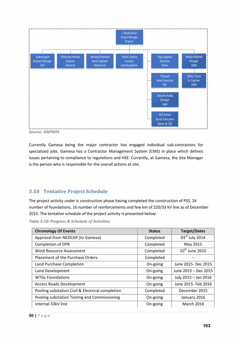
50 | P a g e
Source: ANPWPL
Currently Gamesa being the major contractor has engaged individual sub-contractors for
specialized jobs. Gamesa has a Contractor Management System (CMS) in place which defines
issues pertaining to compliance to regulations and HSE. Currently, at Gamesa, the Site Manager
is the person who is responsible for the overall actions at site.
3.10 Tentative Project Schedule
The project activity under is construction phase having completed the construction of PSS, 24
number of foundations, 16 number of reinforcements and few km of 220/33 kV line as of December
2015. The tentative schedule of the project activity is presented below:
Table 3-10: Progress & Schedule of Activities
C Balakrishnan
Project Manager
Projects
Sankarlingam
Assistant Manager
Civil
Shivkumar Homkar
Engineer
Electrical
T Ramesh
Senior Executive
HSE
Abhishek Reddiwal
Senior Engineer
Mechanical
Vijay Upadhya
Executive
Stores
Mohan Muthiah
Manager
O&M
Adisesha Reddy
Manager
Legal
Anil Kumar
Senior Executive
Admin & CSR
Satish Chandra
Surveyor
Land Acquisition
Mohd. Patani
Sr. Engineer
O&M
Chronology Of Events Status Target/Dates
Approval from NEDCAP (to Gamesa) Completed 03rd July 2014
Completion of DPR Completed May 2015
Wind Resource Assessment Completed 10th June 2015
Placement of the Purchase Orders Completed --
Land Purchase Completion On-going June 2015- Dec 2015
Land Development On-going June 2015 – Dec 2015
WTGs Foundations On-going July 2015 – Jan 2016
Access Roads Development On-going June 2015- Feb 2016
Pooling substation Civil & Electrical completion Completed December 2015
Pooling substation Testing and Commissioning On-going January 2016
Internal 33kV line On-going March 2016
163

51 | P a g e
Line from PSS to Uravakonda Sub station (220/400kV) On-going February 2015
WTGs Commissioning On-going March 2016
Signing of PPA with EB Planned March 2016
164
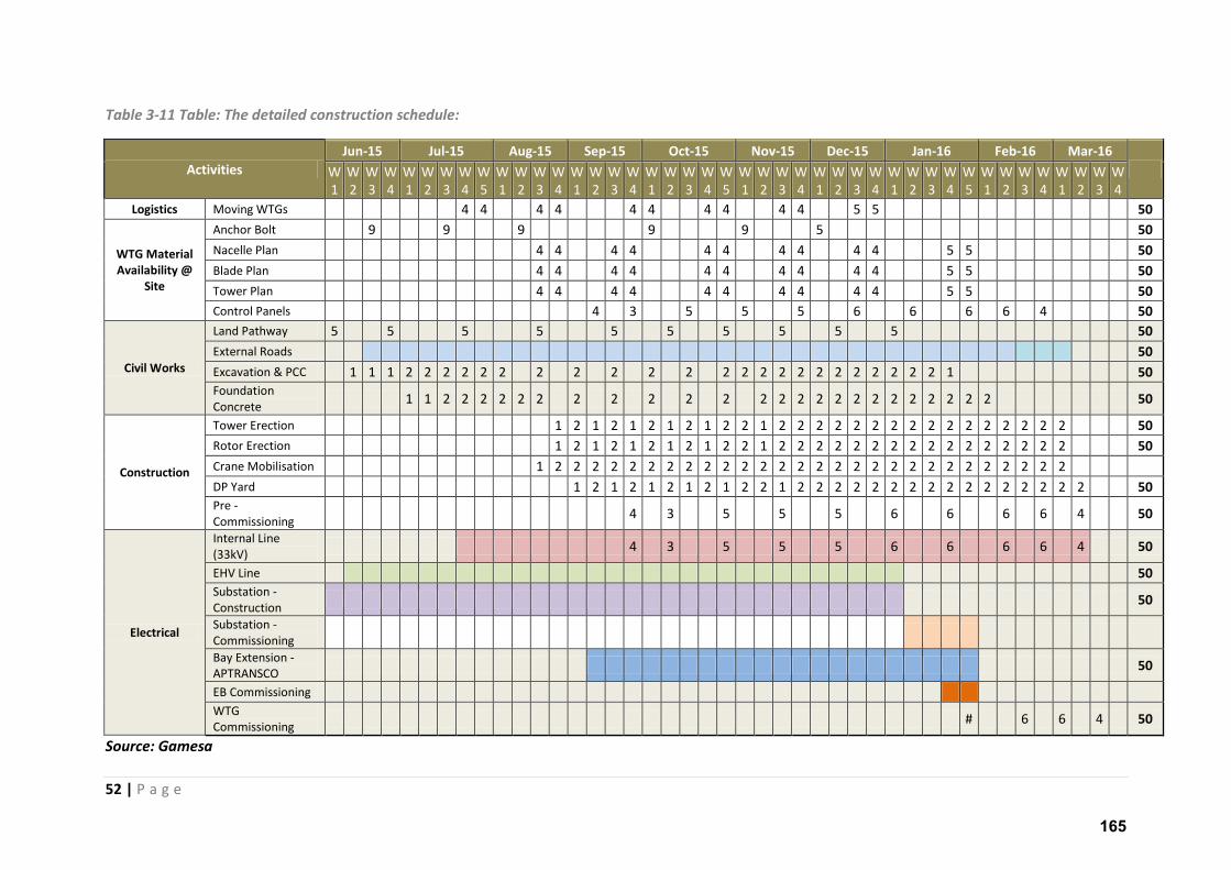
52 | P a g e
Table 3-11 Table: The detailed construction schedule:
Activities
Jun-15 Jul-15 Aug-15 Sep-15 Oct-15 Nov-15 Dec-15 Jan-16 Feb-16 Mar-16
W
1
W
2
W
3
W
4
W
1
W
2
W
3
W
4
W
5
W
1
W
2
W
3
W
4
W
1
W
2
W
3
W
4
W
1
W
2
W
3
W
4
W
5
W
1
W
2
W
3
W
4
W
1
W
2
W
3
W
4
W
1
W
2
W
3
W
4
W
5
W
1
W
2
W
3
W
4
W
1
W
2
W
3
W
4
Logistics Moving WTGs 4 4 4 4 4 4 4 4 4 4 5 5 50
WTG Material
Availability @
Site
Anchor Bolt 9 9 9 9 9 5 50
Nacelle Plan 4 4 4 4 4 4 4 4 4 4 5 5 50
Blade Plan 4 4 4 4 4 4 4 4 4 4 5 5 50
Tower Plan 4 4 4 4 4 4 4 4 4 4 5 5 50
Control Panels 4 3 5 5 5 6 6 6 6 4 50
Civil Works
Land Pathway 5 5 5 5 5 5 5 5 5 5 50
External Roads 50
Excavation & PCC 1 1 1 2 2 2 2 2 2 2 2 2 2 2 2 2 2 2 2 2 2 2 2 2 2 2 1 50
Foundation
Concrete 1 1 2 2 2 2 2 2 2 2 2 2 2 2 2 2 2 2 2 2 2 2 2 2 2 2 50
Construction
Tower Erection 1 2 1 2 1 2 1 2 1 2 2 1 2 2 2 2 2 2 2 2 2 2 2 2 2 2 2 2 50
Rotor Erection 1 2 1 2 1 2 1 2 1 2 2 1 2 2 2 2 2 2 2 2 2 2 2 2 2 2 2 2 50
Crane Mobilisation 1 2 2 2 2 2 2 2 2 2 2 2 2 2 2 2 2 2 2 2 2 2 2 2 2 2 2 2 2
DP Yard 1 2 1 2 1 2 1 2 1 2 2 1 2 2 2 2 2 2 2 2 2 2 2 2 2 2 2 2 50
Pre -
Commissioning 4 3 5 5 5 6 6 6 6
4 50
Electrical
Internal Line
(33kV) 4 3 5 5 5 6 6 6 6 4 50
EHV Line 50
Substation -
Construction 50
Substation -
Commissioning
Bay Extension -
APTRANSCO 50
EB Commissioning
WTG
Commissioning # 6 6 4 50
Source: Gamesa
165
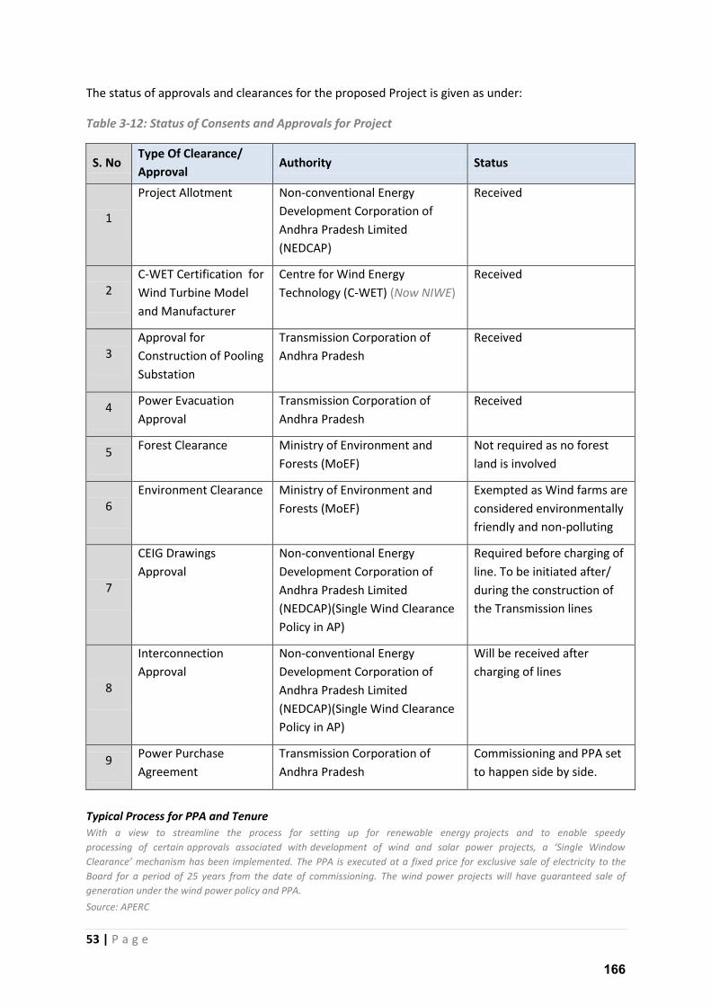
53 | P a g e
The status of approvals and clearances for the proposed Project is given as under:
Table 3-12: Status of Consents and Approvals for Project
S. No Type Of Clearance/
Approval Authority Status
1
Project Allotment Non-conventional Energy
Development Corporation of
Andhra Pradesh Limited
(NEDCAP)
Received
2
C-WET Certification for
Wind Turbine Model
and Manufacturer
Centre for Wind Energy
Technology (C-WET) (Now NIWE)
Received
3
Approval for
Construction of Pooling
Substation
Transmission Corporation of
Andhra Pradesh
Received
4 Power Evacuation
Approval
Transmission Corporation of
Andhra Pradesh
Received
5 Forest Clearance Ministry of Environment and
Forests (MoEF)
Not required as no forest
land is involved
6
Environment Clearance Ministry of Environment and
Forests (MoEF)
Exempted as Wind farms are
considered environmentally
friendly and non-polluting
7
CEIG Drawings
Approval
Non-conventional Energy
Development Corporation of
Andhra Pradesh Limited
(NEDCAP)(Single Wind Clearance
Policy in AP)
Required before charging of
line. To be initiated after/
during the construction of
the Transmission lines
8
Interconnection
Approval
Non-conventional Energy
Development Corporation of
Andhra Pradesh Limited
(NEDCAP)(Single Wind Clearance
Policy in AP)
Will be received after
charging of lines
9 Power Purchase
Agreement
Transmission Corporation of
Andhra Pradesh
Commissioning and PPA set
to happen side by side.
Typical Process for PPA and Tenure With a view to streamline the process for setting up for renewable energy projects and to enable speedy
pro essi g of ertai appro als asso iated ith de elop e t of i d a d solar po er proje ts, a “i gle Wi do Cleara e mechanism has been implemented. The PPA is executed at a fixed price for exclusive sale of electricity to the
Board for a period of 25 years from the date of commissioning. The wind power projects will have guaranteed sale of
generation under the wind power policy and PPA. Source: APERC
166
54 | P a g e
3.11 Corporate Policies
3.11.1 Corporate Policies of ANPWPL:
ANPWPL is part of the Orange Renewable Power Private Limted which is under the umbrella of the
Holodi g o pa O a ge ‘e e a el Holdi g Pte Ltd. O a ge has defi ed Corporate HR policies
and EHS team to implement EHS plans. The EHS team of ANPWPL ensures that the contracts
engaged are of repute and follow required Health and safety guidelines as set forwards by national
and International standards. In the project scenario, Gamesa is the key contract as the project
execution has been complete handed over under the turnkey mode of development. It is further to
be noted that the role of Gamesa is even more crucial as the project Operation and Maintenance
(O&M) will be further under the control of Gamesa.
3.11.2 Corporate Policies of Gamesa
Gamesa is a global technological leader in the wind industry, with a footprint in 54 countries. With
21 years' experience and close to 33,500 MW installed; Gamesa also caters to wind turbine's
operation and maintenance services, that manages for more than 20,600 MW.
Gamesa is part of the leading international sustainability indices: FTSE4Good and FTSE4Good IBEX,
Ethibel Excellence, Cleantech Index, S&P Global Clean Energy Index and Global Challenges Index,
among others.
Gamesa is included in specialized ratings in the fields of renewable energy, sustainability and the
fight against climate change, like Cleantech Index, Global Challengex Index and S&P Global Clean
Energy Index.
According to the Corporate Reputation Monitor (MERCO) report, Gamesa rose to No. 39 in 2012
from No. 48 in 2011. The report, which assesses companies' corporate reputations, has become a
leading benchmark for reputation rankings worldwide since its launch 12 years ago. For the 2012
edition, MERCO polled approximately 1,500 company executives, 658 industry experts, news outlets
and more than 3,000 members of the public. In addition to its overall score, Gamesa ranked No. 27
among the most responsible corporate citizens and companies with the best corporate governance.
Gamesa is also certified with:
ISO 9001:2008 Certificate for Quality Management System from TUV Rhineland, Germany
ISO 14001:2004 Certificate for Environmental Management Systems from from TUV Rhineland,
Germany
BS OHSAS 18001:2007 Certificate for Occupational Health & Safety Management Systems from TUV
Rhineland, Germany
The Corporate Policies of Gamesa are listed below:
167
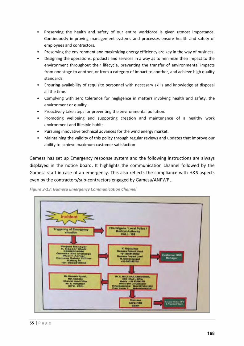
55 | P a g e
• Preserving the health and safety of our entire workforce is given utmost importance.
Continuously improving management systems and processes ensure health and safety of
employees and contractors.
• Preserving the environment and maximizing energy efficiency are key in the way of business.
• Designing the operations, products and services in a way as to minimize their impact to the
environment throughout their lifecycle, preventing the transfer of environmental impacts
from one stage to another, or from a category of impact to another, and achieve high quality
standards.
• Ensuring availability of requisite personnel with necessary skills and knowledge at disposal
all the time.
• Complying with zero tolerance for negligence in matters involving health and safety, the
environment or quality.
• Proactively take steps for preventing the environmental pollution.
• Promoting wellbeing and supporting creation and maintenance of a healthy work
environment and lifestyle habits.
• Pursuing innovative technical advances for the wind energy market.
• Maintaining the validity of this policy through regular reviews and updates that improve our
ability to achieve maximum customer satisfaction
Gamesa has set up Emergency response system and the following instructions are always
displayed in the notice board. It highlights the communication channel followed by the
Gamesa staff in case of an emergency. This also reflects the compliance with H&S aspects
even by the contractors/sub-contractors engaged by Gamesa/ANPWPL.
Figure 3-13: Gamesa Emergency Communication Channel
168
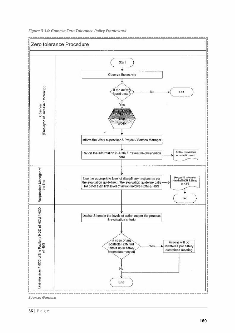
56 | P a g e
Figure 3-14: Gamesa Zero Tolerance Policy Framework
Source: Gamesa
169
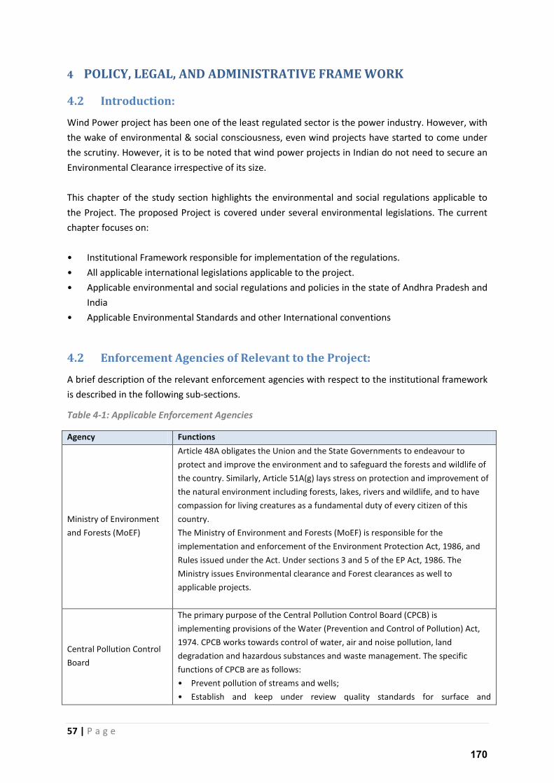
57 | P a g e
4 POLICY, LEGAL, AND ADMINISTRATIVE FRAME WORK
4.2 Introduction:
Wind Power project has been one of the least regulated sector is the power industry. However, with
the wake of environmental & social consciousness, even wind projects have started to come under
the scrutiny. However, it is to be noted that wind power projects in Indian do not need to secure an
Environmental Clearance irrespective of its size.
This chapter of the study section highlights the environmental and social regulations applicable to
the Project. The proposed Project is covered under several environmental legislations. The current
chapter focuses on:
• Institutional Framework responsible for implementation of the regulations.
• All applicable international legislations applicable to the project.
• Applicable environmental and social regulations and policies in the state of Andhra Pradesh and
India
• Applicable Environmental Standards and other International conventions
4.2 Enforcement Agencies of Relevant to the Project:
A brief description of the relevant enforcement agencies with respect to the institutional framework
is described in the following sub-sections.
Table 4-1: Applicable Enforcement Agencies
Agency Functions
Ministry of Environment
and Forests (MoEF)
Article 48A obligates the Union and the State Governments to endeavour to
protect and improve the environment and to safeguard the forests and wildlife of
the country. Similarly, Article 51A(g) lays stress on protection and improvement of
the natural environment including forests, lakes, rivers and wildlife, and to have
compassion for living creatures as a fundamental duty of every citizen of this
country.
The Ministry of Environment and Forests (MoEF) is responsible for the
implementation and enforcement of the Environment Protection Act, 1986, and
Rules issued under the Act. Under sections 3 and 5 of the EP Act, 1986. The
Ministry issues Environmental clearance and Forest clearances as well to
applicable projects.
Central Pollution Control
Board
The primary purpose of the Central Pollution Control Board (CPCB) is
implementing provisions of the Water (Prevention and Control of Pollution) Act,
1974. CPCB works towards control of water, air and noise pollution, land
degradation and hazardous substances and waste management. The specific
functions of CPCB are as follows:
• Prevent pollution of streams and wells;
• Establish and keep under review quality standards for surface and
170
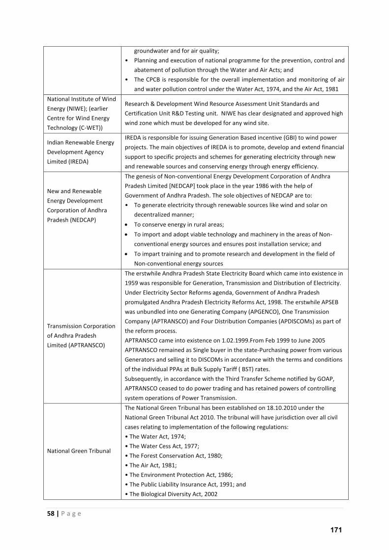
58 | P a g e
groundwater and for air quality;
• Planning and execution of national programme for the prevention, control and
abatement of pollution through the Water and Air Acts; and
• The CPCB is responsible for the overall implementation and monitoring of air
and water pollution control under the Water Act, 1974, and the Air Act, 1981
National Institute of Wind
Energy (NIWE); (earlier
Centre for Wind Energy
Technology (C-WET))
Research & Development Wind Resource Assessment Unit Standards and
Certification Unit R&D Testing unit. NIWE has clear designated and approved high
wind zone which must be developed for any wind site.
Indian Renewable Energy
Development Agency
Limited (IREDA)
IREDA is responsible for issuing Generation Based incentive (GBI) to wind power
projects. The main objectives of IREDA is to promote, develop and extend financial
support to specific projects and schemes for generating electricity through new
and renewable sources and conserving energy through energy efficiency.
New and Renewable
Energy Development
Corporation of Andhra
Pradesh (NEDCAP)
The genesis of Non-conventional Energy Development Corporation of Andhra
Pradesh Limited [NEDCAP] took place in the year 1986 with the help of
Government of Andhra Pradesh. The sole objectives of NEDCAP are to:
• To generate electricity through renewable sources like wind and solar on
decentralized manner;
To conserve energy in rural areas;
To import and adopt viable technology and machinery in the areas of Non-
conventional energy sources and ensures post installation service; and
To impart training and to promote research and development in the field of
Non-conventional energy sources
Transmission Corporation
of Andhra Pradesh
Limited (APTRANSCO)
The erstwhile Andhra Pradesh State Electricity Board which came into existence in
1959 was responsible for Generation, Transmission and Distribution of Electricity.
Under Electricity Sector Reforms agenda, Government of Andhra Pradesh
promulgated Andhra Pradesh Electricity Reforms Act, 1998. The erstwhile APSEB
was unbundled into one Generating Company (APGENCO), One Transmission
Company (APTRANSCO) and Four Distribution Companies (APDISCOMs) as part of
the reform process.
APTRANSCO came into existence on 1.02.1999.From Feb 1999 to June 2005
APTRANSCO remained as Single buyer in the state-Purchasing power from various
Generators and selling it to DISCOMs in accordance with the terms and conditions
of the individual PPAs at Bulk Supply Tariff ( BST) rates.
Subsequently, in accordance with the Third Transfer Scheme notified by GOAP,
APTRANSCO ceased to do power trading and has retained powers of controlling
system operations of Power Transmission.
National Green Tribunal
The National Green Tribunal has been established on 18.10.2010 under the
National Green Tribunal Act 2010. The tribunal will have jurisdiction over all civil
cases relating to implementation of the following regulations:
• The Wate A t, ; • The Wate Cess A t, ; • The Fo est Co se atio A t, ; • The Ai A t, ; • The E i o e t P ote tio Act, 1986;
• The Pu li Lia ilit I su a e A t, ; a d
• The Biologi al Di e sit A t,
171
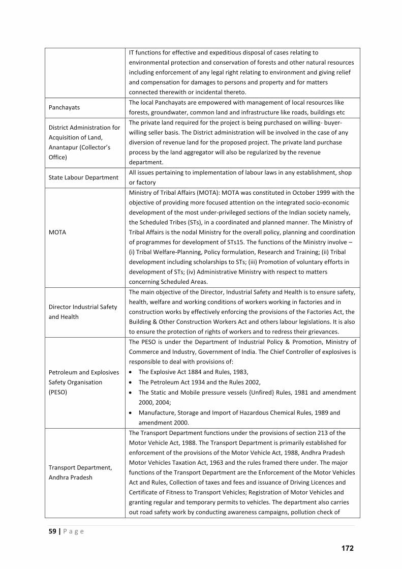
59 | P a g e
IT functions for effective and expeditious disposal of cases relating to
environmental protection and conservation of forests and other natural resources
including enforcement of any legal right relating to environment and giving relief
and compensation for damages to persons and property and for matters
connected therewith or incidental thereto.
Panchayats The local Panchayats are empowered with management of local resources like
forests, groundwater, common land and infrastructure like roads, buildings etc
District Administration for
Acquisition of Land,
A a tapu Colle to s Office)
The private land required for the project is being purchased on willing- buyer-
willing seller basis. The District administration will be involved in the case of any
diversion of revenue land for the proposed project. The private land purchase
process by the land aggregator will also be regularized by the revenue
department.
State Labour Department All issues pertaining to implementation of labour laws in any establishment, shop
or factory
MOTA
Ministry of Tribal Affairs (MOTA): MOTA was constituted in October 1999 with the
objective of providing more focused attention on the integrated socio-economic
development of the most under-privileged sections of the Indian society namely,
the Scheduled Tribes (STs), in a coordinated and planned manner. The Ministry of
Tribal Affairs is the nodal Ministry for the overall policy, planning and coordination
of programmes for development of STs15. The functions of the Ministry involve –
(i) Tribal Welfare-Planning, Policy formulation, Research and Training; (ii) Tribal
development including scholarships to STs; (iii) Promotion of voluntary efforts in
development of STs; (iv) Administrative Ministry with respect to matters
concerning Scheduled Areas.
Director Industrial Safety
and Health
The main objective of the Director, Industrial Safety and Health is to ensure safety,
health, welfare and working conditions of workers working in factories and in
construction works by effectively enforcing the provisions of the Factories Act, the
Building & Other Construction Workers Act and others labour legislations. It is also
to ensure the protection of rights of workers and to redress their grievances.
Petroleum and Explosives
Safety Organisation
(PESO)
The PESO is under the Department of Industrial Policy & Promotion, Ministry of
Commerce and Industry, Government of India. The Chief Controller of explosives is
responsible to deal with provisions of:
The Explosive Act 1884 and Rules, 1983,
The Petroleum Act 1934 and the Rules 2002,
The Static and Mobile pressure vessels {Unfired} Rules, 1981 and amendment
2000, 2004;
Manufacture, Storage and Import of Hazardous Chemical Rules, 1989 and
amendment 2000.
Transport Department,
Andhra Pradesh
The Transport Department functions under the provisions of section 213 of the
Motor Vehicle Act, 1988. The Transport Department is primarily established for
enforcement of the provisions of the Motor Vehicle Act, 1988, Andhra Pradesh
Motor Vehicles Taxation Act, 1963 and the rules framed there under. The major
functions of the Transport Department are the Enforcement of the Motor Vehicles
Act and Rules, Collection of taxes and fees and issuance of Driving Licences and
Certificate of Fitness to Transport Vehicles; Registration of Motor Vehicles and
granting regular and temporary permits to vehicles. The department also carries
out road safety work by conducting awareness campaigns, pollution check of
172

60 | P a g e
vehicles and enforce measures such booking speeding vehicles through laser guns
and interceptor vehicles and detect drunken drivers through breath analysers.
Other international standard for regulation of wind power projects such as IFC Performance
standards, Equator Principles, and IFC EHS Guidelines for wind power project are not described in
the table above as the same are detailed in the following sections of this chapter.
173
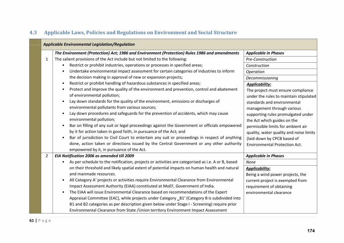
61 | P a g e
4.3 Applicable Laws, Policies and Regulations on Environment and Social Structure
Applicable Environmental Legislation/Regulation
1
The Environment (Protection) Act; 1986 and Environment (Protection) Rules 1986 and amendments
The salient provisions of the Act include but not limited to the following:
• Restrict or prohibit industries, operations or processes in specified areas;
• Undertake environmental impact assessment for certain categories of industries to inform
the decision making in approval of new or expansion projects;
• Restrict or prohibit handling of hazardous substances in specified areas;
• Protect and improve the quality of the environment and prevention, control and abatement
of environmental pollution;
• Lay down standards for the quality of the environment, emissions or discharges of
environmental pollutants from various sources;
• Lay down procedures and safeguards for the prevention of accidents, which may cause
environmental pollution;
• Bar on filling of any suit or legal proceedings against the Government or officials empowered
by it for action taken in good faith, in pursuance of the Act; and
• Bar of jurisdiction to Civil Court to entertain any suit or proceedings in respect of anything
done, action taken or directions issued by the Central Government or any other authority
empowered by it, in pursuance of the Act.
Applicable in Phases
Pre-Construction
Construction
Operation
Decommissioning
Applicability:
The project must ensure compliance
under the rules to maintain stipulated
standards and environmental
management through various
supporting rules promulgated under
the Act which guides on the
permissible limits for ambient air
quality, water quality and noise limits
(laid down by CPCB based of
Environmental Protection Act.
2
EIA Notification 2006 as amended till 2009
• As per schedule to the notification, projects or activities are categorised as i.e. A or B, based
on their threshold and likely spatial extent of potential impacts on human health and natural
and manmade resources.
• All Catego A p oje ts o a ti ities require Environmental Clearance from Environmental
Impact Assessment Authority (EIAA) constituted at MoEF, Government of India.
• The EIAA will issue Environmental Clearance based on recommendations of the Expert
Appraisal Committee (EAC), while projects u de Catego ‗B Catego B is su di ided i to B1 and B2 categories as per description given below under Stage I - Screening) require prior
Environmental Clearance from State /Union territory Environment Impact Assessment
Applicable in Phases
None
Applicability:
Being a wind power projects, the
current project is exempted from
requirement of obtaining
environmental clearance
174
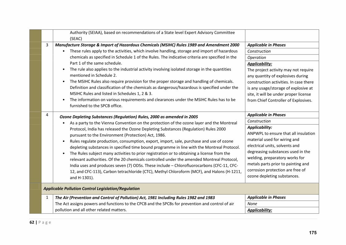
62 | P a g e
Authority (SEIAA), based on recommendations of a State level Expert Advisory Committee
(SEAC)
3 Manufacture Storage & Import of Hazardous Chemicals (MSIHC) Rules 1989 and Amendment 2000
• These rules apply to the activities, which involve handling, storage and import of hazardous
chemicals as specified in Schedule 1 of the Rules. The indicative criteria are specified in the
Part 1 of the same schedule.
• The rule also applies to the industrial activity involving isolated storage in the quantities
mentioned in Schedule 2.
• The MSIHC Rules also require provision for the proper storage and handling of chemicals.
Definition and classification of the chemicals as dangerous/hazardous is specified under the
MSIHC Rules and listed in Schedules 1, 2 & 3.
• The information on various requirements and clearances under the MSIHC Rules has to be
furnished to the SPCB office.
Applicable in Phases
Construction
Operation
Applicability:
The project activity may not require
any quantity of explosives during
construction activities. In case there
is any usage/storage of explosive at
site, it will be under proper license
from Chief Controller of Explosives.
4 Ozone Depleting Substances (Regulation) Rules, 2000 as amended in 2005
• As a party to the Vienna Convention on the protection of the ozone layer and the Montreal
Protocol, India has released the Ozone Depleting Substances (Regulation) Rules 2000
pursuant to the Environment (Protection) Act, 1986.
• Rules regulate production, consumption, export, import, sale, purchase and use of ozone
depleting substances in specified time bound programme in line with the Montreal Protocol.
• The Rules subject many activities to prior registration or to obtaining a license from the
relevant authorities. Of the 20 chemicals controlled under the amended Montreal Protocol,
India uses and produces seven (7) ODSs. These include – Chlorofluorocarbons (CFC-11, CFC-
12, and CFC-113), Carbon tetrachloride (CTC), Methyl Chloroform (MCF), and Halons (H-1211,
and H-1301).
Applicable in Phases
Construction
Applicability:
ANPWPL to ensure that all insulation
material used for wiring and
electrical units, solvents and
degreasing substances used in the
welding, preparatory works for
metals parts prior to painting and
corrosion protection are free of
ozone depleting substances.
Applicable Pollution Control Legislation/Regulation
1
The Air (Prevention and Control of Pollution) Act, 1981 Including Rules 1982 and 1983
The Act assigns powers and functions to the CPCB and the SPCBs for prevention and control of air
pollution and all other related matters.
Applicable in Phases
None
Applicability:
175
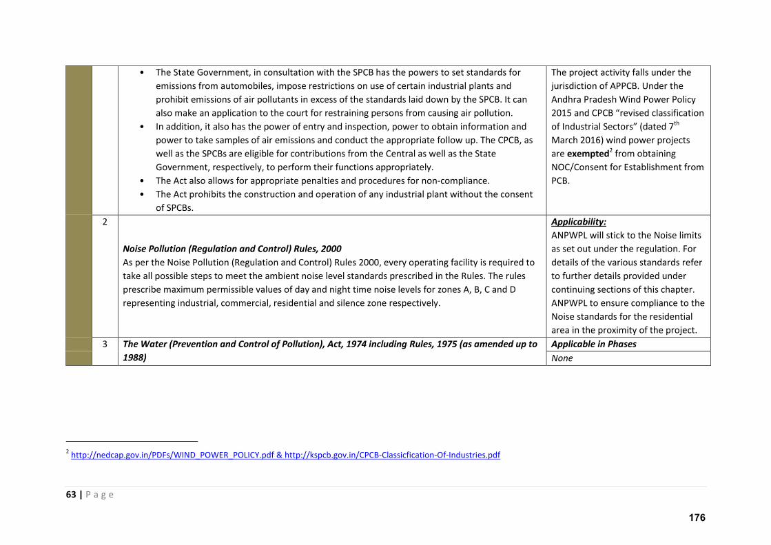
63 | P a g e
• The State Government, in consultation with the SPCB has the powers to set standards for
emissions from automobiles, impose restrictions on use of certain industrial plants and
prohibit emissions of air pollutants in excess of the standards laid down by the SPCB. It can
also make an application to the court for restraining persons from causing air pollution.
• In addition, it also has the power of entry and inspection, power to obtain information and
power to take samples of air emissions and conduct the appropriate follow up. The CPCB, as
well as the SPCBs are eligible for contributions from the Central as well as the State
Government, respectively, to perform their functions appropriately.
• The Act also allows for appropriate penalties and procedures for non-compliance.
• The Act prohibits the construction and operation of any industrial plant without the consent
of SPCBs.
The project activity falls under the
jurisdiction of APPCB. Under the
Andhra Pradesh Wind Power Policy
a d CPCB e ised lassifi atio of I dust ial “e to s dated th
March 2016) wind power projects
are exempted2 from obtaining
NOC/Consent for Establishment from
PCB.
2
Noise Pollution (Regulation and Control) Rules, 2000
As per the Noise Pollution (Regulation and Control) Rules 2000, every operating facility is required to
take all possible steps to meet the ambient noise level standards prescribed in the Rules. The rules
prescribe maximum permissible values of day and night time noise levels for zones A, B, C and D
representing industrial, commercial, residential and silence zone respectively.
Applicability:
ANPWPL will stick to the Noise limits
as set out under the regulation. For
details of the various standards refer
to further details provided under
continuing sections of this chapter.
ANPWPL to ensure compliance to the
Noise standards for the residential
area in the proximity of the project.
3 The Water (Prevention and Control of Pollution), Act, 1974 including Rules, 1975 (as amended up to
1988)
Applicable in Phases
None
2 http://nedcap.gov.in/PDFs/WIND_POWER_POLICY.pdf & http://kspcb.gov.in/CPCB-Classicfication-Of-Industries.pdf
176
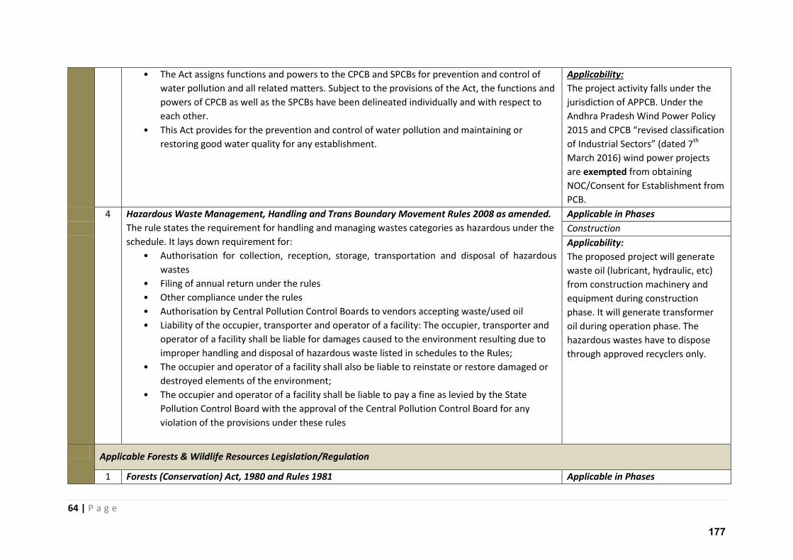
64 | P a g e
• The Act assigns functions and powers to the CPCB and SPCBs for prevention and control of
water pollution and all related matters. Subject to the provisions of the Act, the functions and
powers of CPCB as well as the SPCBs have been delineated individually and with respect to
each other.
• This Act provides for the prevention and control of water pollution and maintaining or
restoring good water quality for any establishment.
Applicability:
The project activity falls under the
jurisdiction of APPCB. Under the
Andhra Pradesh Wind Power Policy
a d CPCB e ised lassifi atio of I dust ial “e to s dated th
March 2016) wind power projects
are exempted from obtaining
NOC/Consent for Establishment from
PCB.
4 Hazardous Waste Management, Handling and Trans Boundary Movement Rules 2008 as amended.
The rule states the requirement for handling and managing wastes categories as hazardous under the
schedule. It lays down requirement for:
• Authorisation for collection, reception, storage, transportation and disposal of hazardous
wastes
• Filing of annual return under the rules
• Other compliance under the rules
• Authorisation by Central Pollution Control Boards to vendors accepting waste/used oil
• Liability of the occupier, transporter and operator of a facility: The occupier, transporter and
operator of a facility shall be liable for damages caused to the environment resulting due to
improper handling and disposal of hazardous waste listed in schedules to the Rules;
• The occupier and operator of a facility shall also be liable to reinstate or restore damaged or
destroyed elements of the environment;
• The occupier and operator of a facility shall be liable to pay a fine as levied by the State
Pollution Control Board with the approval of the Central Pollution Control Board for any
violation of the provisions under these rules
Applicable in Phases
Construction
Applicability:
The proposed project will generate
waste oil (lubricant, hydraulic, etc)
from construction machinery and
equipment during construction
phase. It will generate transformer
oil during operation phase. The
hazardous wastes have to dispose
through approved recyclers only.
Applicable Forests & Wildlife Resources Legislation/Regulation
1 Forests (Conservation) Act, 1980 and Rules 1981 Applicable in Phases
177
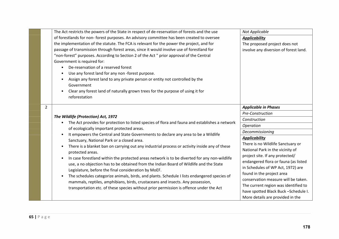
65 | P a g e
The Act restricts the powers of the State in respect of de-reservation of forests and the use
of forestlands for non- forest purposes. An advisory committee has been created to oversee
the implementation of the statute. The FCA is relevant for the power the project, and for
passage of transmission through forest areas, since it would involve use of forestland for
o -fo est pu poses. A o di g to “e tio of the A t " p io app o al of the Ce t al Government is required for:
• De-reservation of a reserved forest
• Use any forest land for any non -forest purpose.
• Assign any forest land to any private person or entity not controlled by the
Government
• Clear any forest land of naturally grown trees for the purpose of using it for
reforestation
Not Applicable
Applicability
The proposed project does not
involve any diversion of forest land.
2
The Wildlife (Protection) Act, 1972
• The Act provides for protection to listed species of flora and fauna and establishes a network
of ecologically important protected areas.
• It empowers the Central and State Governments to declare any area to be a Wildlife
Sanctuary, National Park or a closed area.
• There is a blanket ban on carrying out any industrial process or activity inside any of these
protected areas.
• In case forestland within the protected areas network is to be diverted for any non-wildlife
use, a no objection has to be obtained from the Indian Board of Wildlife and the State
Legislature, before the final consideration by MoEF.
• The schedules categorize animals, birds, and plants. Schedule I lists endangered species of
mammals, reptiles, amphibians, birds, crustaceans and insects. Any possession,
transportation etc. of these species without prior permission is offence under the Act
Applicable in Phases
Pre-Construction
Construction
Operation
Decommissioning
Applicability
There is no Wildlife Sanctuary or
National Park in the vicinity of
project site. If any protected/
endangered flora or fauna (as listed
in Schedules of WP Act, 1972) are
found in the project area
conservation measure will be taken.
The current region was identified to
have spotted Black Buck –Schedule I.
More details are provided in the
178
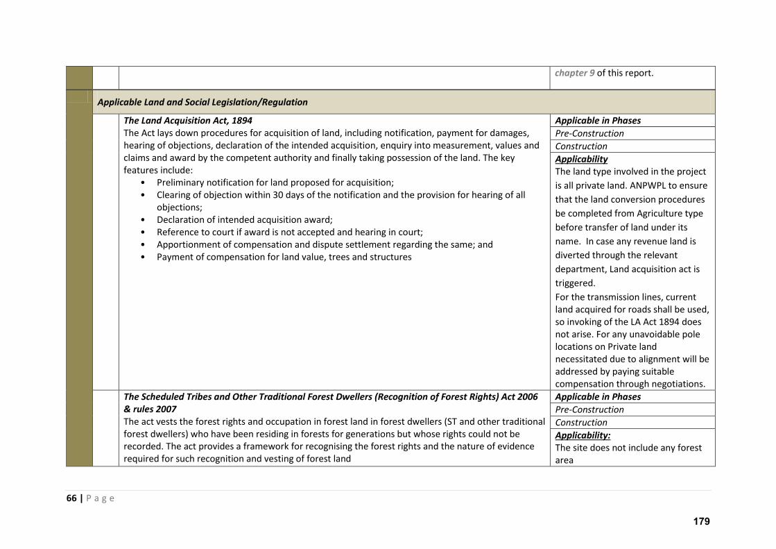
66 | P a g e
chapter 9 of this report.
Applicable Land and Social Legislation/Regulation
The Land Acquisition Act, 1894
The Act lays down procedures for acquisition of land, including notification, payment for damages,
hearing of objections, declaration of the intended acquisition, enquiry into measurement, values and
claims and award by the competent authority and finally taking possession of the land. The key
features include:
• Preliminary notification for land proposed for acquisition;
• Clearing of objection within 30 days of the notification and the provision for hearing of all
objections;
• Declaration of intended acquisition award;
• Reference to court if award is not accepted and hearing in court;
• Apportionment of compensation and dispute settlement regarding the same; and
• Payment of compensation for land value, trees and structures
Applicable in Phases
Pre-Construction
Construction
Applicability
The land type involved in the project
is all private land. ANPWPL to ensure
that the land conversion procedures
be completed from Agriculture type
before transfer of land under its
name. In case any revenue land is
diverted through the relevant
department, Land acquisition act is
triggered. For the transmission lines, current
land acquired for roads shall be used,
so invoking of the LA Act 1894 does
not arise. For any unavoidable pole
locations on Private land
necessitated due to alignment will be
addressed by paying suitable
compensation through negotiations.
The Scheduled Tribes and Other Traditional Forest Dwellers (Recognition of Forest Rights) Act 2006
& rules 2007
The act vests the forest rights and occupation in forest land in forest dwellers (ST and other traditional
forest dwellers) who have been residing in forests for generations but whose rights could not be
recorded. The act provides a framework for recognising the forest rights and the nature of evidence
required for such recognition and vesting of forest land
Applicable in Phases
Pre-Construction
Construction
Applicability:
The site does not include any forest
area
179
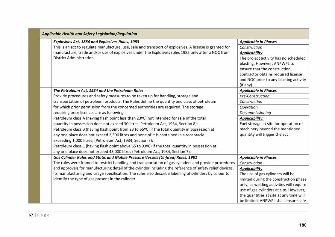
67 | P a g e
Applicable Health and Safety Legislation/Regulation
Explosives Act, 1884 and Explosives Rules, 1983
This is an act to regulate manufacture, use, sale and transport of explosives. A license is granted for
manufacture, trade and/or use of explosives under the Explosives rules 1983 only after a NOC from
District Administration.
Applicable in Phases
Construction
Applicability
The project activity has no scheduled
blasting. However, ANPWPL to
ensure that the construction
contractor obtains required license
and NOC prior to any blasting activity
(if any)
The Petroleum Act, 1934 and the Petroleum Rules
Provide procedures and safety measures to be taken up for handling, storage and
transportation of petroleum products. The Rules define the quantity and class of petroleum
for which prior permission from the concerned authorities are required. The storage
requiring prior licences are as following:
Petroleum class A (having flash point less than 23ºC) not intended for sale of the total
quantity in possession does not exceed 30 litres. Petroleum Act, 1934, Section 8);
Petroleum class B (having flash point from 23 to 65ºC) if the total quantity in possession at
any one place does not exceed 2,500 litres and none of it is contained in a receptacle
exceeding 1,000 litres; (Petroleum Act, 1934, Section 7);
Petroleum class C (having flash point above 65 to 93ºC) if the total quantity in possession at
any one place does not exceed 45,000 litres (Petroleum Act, 1934, Section 7).
Applicable in Phases
Pre-Construction
Construction
Operation
Decommissioning
Applicability:
Fuel storage at site for operation of
machinery beyond the mentioned
quantity will trigger the act
Gas Cylinder Rules and Static and Mobile Pressure Vessels (Unfired) Rules, 1981
The rules were framed to restrict handling and transportation of gas cylinders and provide procedures
and approvals for manufacturing detail of the cylinder including the reference of safety relief devices,
its manufacturing and usage specification. The rules also describe labelling of cylinders by colour to
identify the type of gas present in the cylinder
Applicable in Phases
Construction
Applicability
The use of gas cylinders will be
limited during the construction phase
only; as welding activities will require
use of gas cylinders at site. However,
the quantities at site at any time will
be limited. ANPWPL shall ensure safe
180
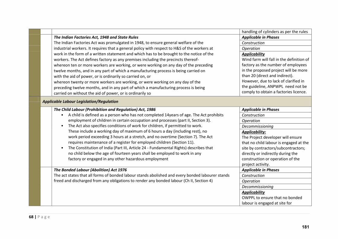
68 | P a g e
handling of cylinders as per the rules
The Indian Factories Act, 1948 and State Rules
The Indian Factories Act was promulgated in 1948, to ensure general welfare of the
industrial workers. It requires that a general policy with respect to H&S of the workers at
work in the form of a written statement and which has to be brought to the notice of the
workers. The Act defines factory as any premises including the precincts thereof-
whereon ten or more workers are working, or were working on any day of the preceding
twelve months, and in any part of which a manufacturing process is being carried on
with the aid of power, or is ordinarily so carried on, or
whereon twenty or more workers are working, or were working on any day of the
preceding twelve months, and in any part of which a manufacturing process is being
carried on without the aid of power, or is ordinarily so
Applicable in Phases
Construction
Operation
Applicability
Wind farm will fall in the definition of
factory as the number of employees
in the proposed project will be more
than 20 (direct and indirect).
However, due to lack of clarified in
the guideline, ANPWPL need not be
comply to obtain a factories licence.
Applicable Labour Legislation/Regulation
The Child Labour (Prohibition and Regulation) Act, 1986
• A child is defined as a person who has not completed 14years of age. The Act prohibits
employment of children in certain occupation and processes (part II, Section 3).
• The Act also specifies conditions of work for children, if permitted to work.
These include a working day of maximum of 6 hours a day (including rest), no
work period exceeding 3 hours at a stretch, and no overtime (Section 7). The Act
requires maintenance of a register for employed children (Section 11).
• The Constitution of India (Part III, Article 24 - Fundamental Rights) describes that
no child below the age of fourteen years shall be employed to work in any
factory or engaged in any other hazardous employment
Applicable in Phases
Construction
Operation
Decommissioning
Applicability:
The Project developer will ensure
that no child labour is engaged at the
site by contractors/subcontractors;
directly or indirectly during the
construction or operation of the
project activity.
The Bonded Labour (Abolition) Act 1976
The act states that all forms of bonded labour stands abolished and every bonded labourer stands
freed and discharged from any obligations to render any bonded labour (Ch II, Section 4)
Applicable in Phases
Construction
Operation
Decommissioning
Applicability
OWPPL to ensure that no bonded
labour is engaged at site for
181
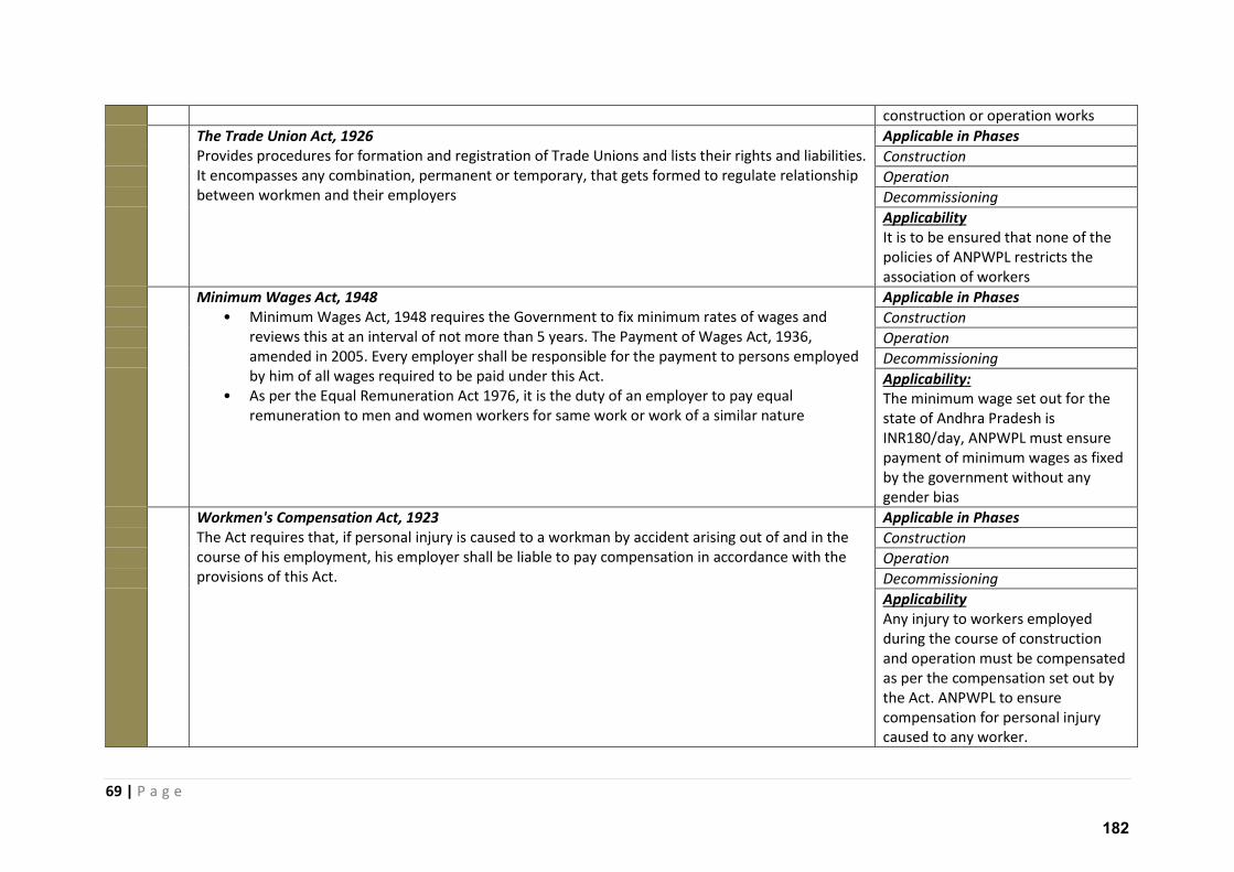
69 | P a g e
construction or operation works
The Trade Union Act, 1926
Provides procedures for formation and registration of Trade Unions and lists their rights and liabilities.
It encompasses any combination, permanent or temporary, that gets formed to regulate relationship
between workmen and their employers
Applicable in Phases
Construction
Operation
Decommissioning
Applicability
It is to be ensured that none of the
policies of ANPWPL restricts the
association of workers
Minimum Wages Act, 1948
• Minimum Wages Act, 1948 requires the Government to fix minimum rates of wages and
reviews this at an interval of not more than 5 years. The Payment of Wages Act, 1936,
amended in 2005. Every employer shall be responsible for the payment to persons employed
by him of all wages required to be paid under this Act.
• As per the Equal Remuneration Act 1976, it is the duty of an employer to pay equal
remuneration to men and women workers for same work or work of a similar nature
Applicable in Phases
Construction
Operation
Decommissioning
Applicability:
The minimum wage set out for the
state of Andhra Pradesh is
INR180/day, ANPWPL must ensure
payment of minimum wages as fixed
by the government without any
gender bias
Workmen's Compensation Act, 1923
The Act requires that, if personal injury is caused to a workman by accident arising out of and in the
course of his employment, his employer shall be liable to pay compensation in accordance with the
provisions of this Act.
Applicable in Phases
Construction
Operation
Decommissioning
Applicability
Any injury to workers employed
during the course of construction
and operation must be compensated
as per the compensation set out by
the Act. ANPWPL to ensure
compensation for personal injury
caused to any worker.
182
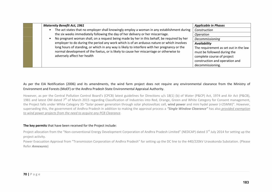
70 | P a g e
Maternity Benefit Act, 1961
• The act states that no employer shall knowingly employ a woman in any establishment during
the six weeks immediately following the day of her delivery or her miscarriage.
• No pregnant woman shall, on a request being made by her in this behalf, be required by her
employer to do during the period any work which is of an arduous nature or which involves
long hours of standing, or which in any way is likely to interfere with her pregnancy or the
normal development of the foetus, or is likely to cause her miscarriage or otherwise to
adversely affect her health
Applicable in Phases
Construction
Operation
Decommissioning
Availability
The requirement as set out in the law
must be followed during the
complete course of project
construction and operation and
decommissioning.
As per the EIA Notification (2006) and its amendments, the wind farm project does not require any environmental clearance from the Ministry of
Environment and Forests (MoEF) or the Andhra Pradesh State Environmental Appraisal Authority.
Ho e e , as pe the Ce t al Pollutio Co t ol Boa d s CPCB latest guideli es fo Di e tio s u/s of Wate P&CP Act, 1974 and Air Act (P&CB),
1981 and latest OM dated 7th of March 2015 regarding Classification of Industries into Red, Orange, Green and White Category for Consent management,
the Project falls under White Category 35- Solar power generation through solar photovoltaic cell, wind power and mini hydel power (<25MW) . Ho e e , superseding this, the government of Andhra Pradesh in addition to making the approval process a “i gle Wi do Cleara e has also provided exemption
to wind power projects from the need to acquire any PCB Clearance.
The key permits that have been received for the Project include:
P oje t allo atio f o the No - o e tio al E e g De elop e t Co po atio of A dh a P adesh Li ited NEDCAP dated rd July 2014 for setting up the
project activity.
Po e E a uatio App o al f o T a s issio Co po atio of A dh a P adesh fo setti g up the DC li e to the / kV U a ako da “u statio . (Please
Refer Annexures)
183
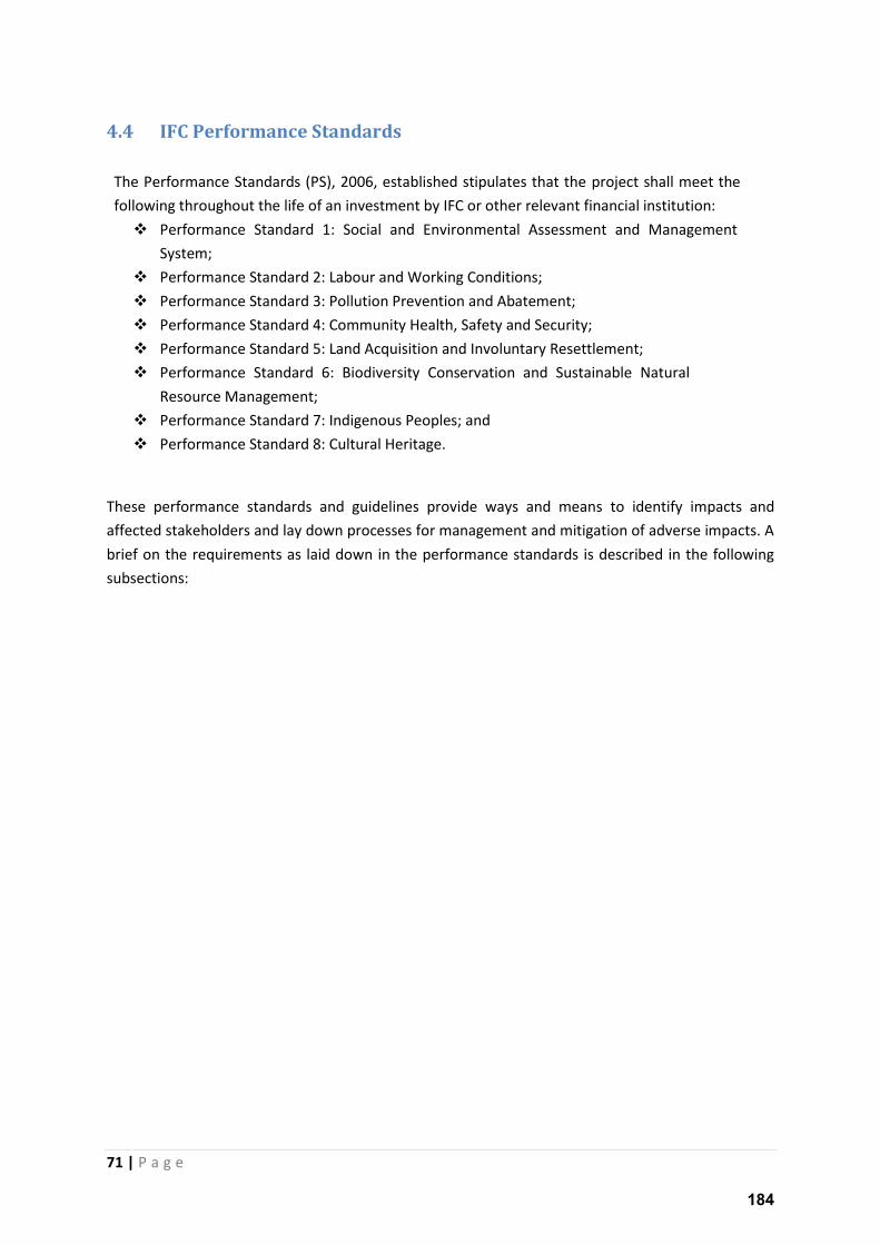
71 | P a g e
4.4 IFC Performance Standards
The Performance Standards (PS), 2006, established stipulates that the project shall meet the
following throughout the life of an investment by IFC or other relevant financial institution:
Performance Standard 1: Social and Environmental Assessment and Management
System;
Performance Standard 2: Labour and Working Conditions;
Performance Standard 3: Pollution Prevention and Abatement;
Performance Standard 4: Community Health, Safety and Security;
Performance Standard 5: Land Acquisition and Involuntary Resettlement;
Performance Standard 6: Biodiversity Conservation and Sustainable Natural
Resource Management;
Performance Standard 7: Indigenous Peoples; and
Performance Standard 8: Cultural Heritage.
These performance standards and guidelines provide ways and means to identify impacts and
affected stakeholders and lay down processes for management and mitigation of adverse impacts. A
brief on the requirements as laid down in the performance standards is described in the following
subsections:
184
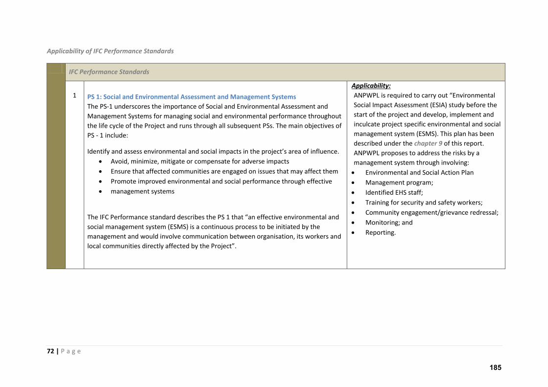
72 | P a g e
Applicability of IFC Performance Standards
IFC Performance Standards
1 PS 1: Social and Environmental Assessment and Management Systems
The PS-1 underscores the importance of Social and Environmental Assessment and
Management Systems for managing social and environmental performance throughout
the life cycle of the Project and runs through all subsequent PSs. The main objectives of
PS - 1 include:
Ide tif a d assess e i o e tal a d so ial i pa ts i the p oje t s a ea of i flue e. Avoid, minimize, mitigate or compensate for adverse impacts
Ensure that affected communities are engaged on issues that may affect them
Promote improved environmental and social performance through effective
management systems
The IFC Performance standard describes the P“ that a effe ti e e i o e tal a d social management system (ESMS) is a continuous process to be initiated by the
management and would involve communication between organisation, its workers and
lo al o u ities di e tl affe ted the P oje t .
Applicability:
ANPWPL is e ui ed to a out E i o e tal Social Impact Assessment (ESIA) study before the
start of the project and develop, implement and
inculcate project specific environmental and social
management system (ESMS). This plan has been
described under the chapter 9 of this report.
ANPWPL proposes to address the risks by a
management system through involving:
Environmental and Social Action Plan
Management program;
Identified EHS staff;
Training for security and safety workers;
Community engagement/grievance redressal;
Monitoring; and
Reporting.
185
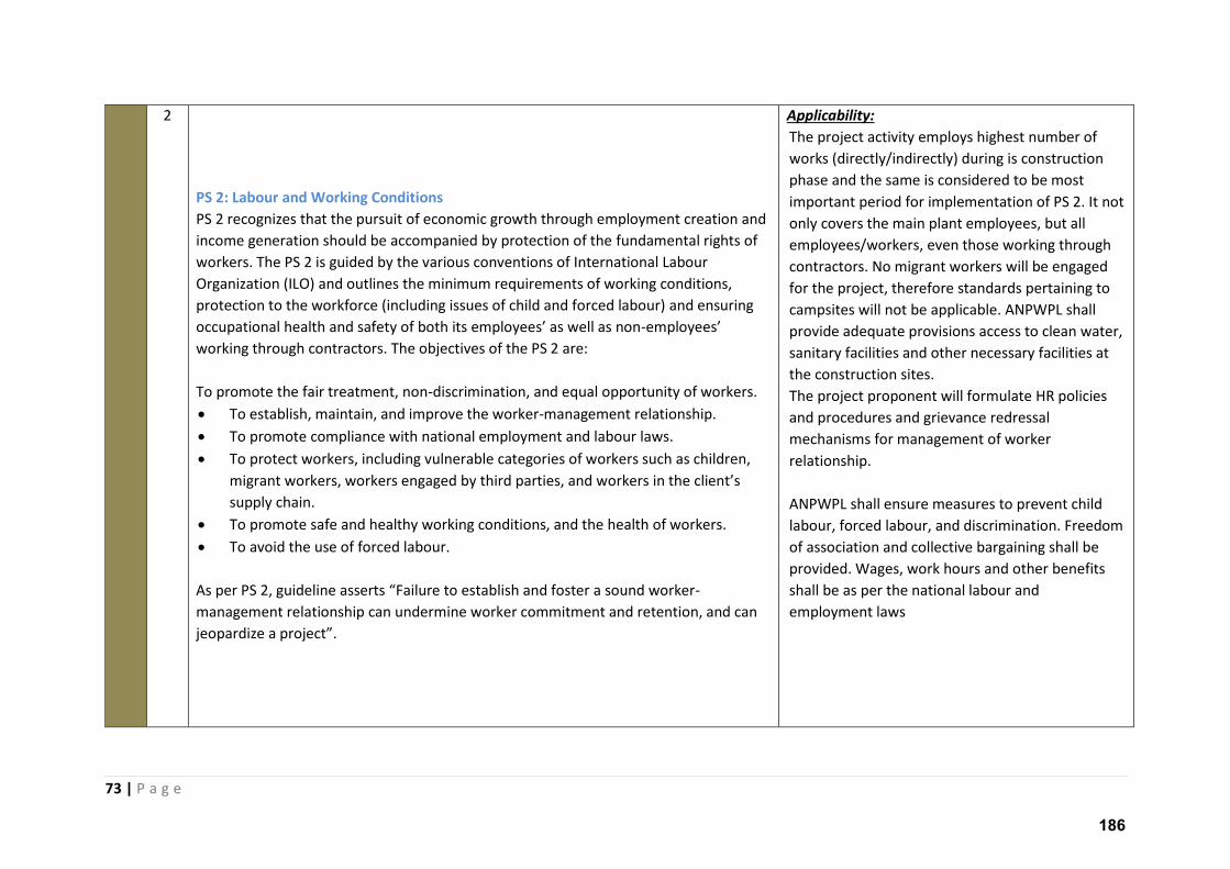
73 | P a g e
2
PS 2: Labour and Working Conditions
PS 2 recognizes that the pursuit of economic growth through employment creation and
income generation should be accompanied by protection of the fundamental rights of
workers. The PS 2 is guided by the various conventions of International Labour
Organization (ILO) and outlines the minimum requirements of working conditions,
protection to the workforce (including issues of child and forced labour) and ensuring
occupational health a d safet of oth its e plo ees as ell as o -e plo ees
working through contractors. The objectives of the PS 2 are:
To promote the fair treatment, non-discrimination, and equal opportunity of workers.
To establish, maintain, and improve the worker-management relationship.
To promote compliance with national employment and labour laws.
To protect workers, including vulnerable categories of workers such as children,
migrant workers, workers engaged by third parties, a d o ke s i the lie t s supply chain.
To promote safe and healthy working conditions, and the health of workers.
To avoid the use of forced labour.
As pe P“ , guideli e asse ts Failu e to esta lish a d foste a sou d o ke -
management relationship can undermine worker commitment and retention, and can
jeopa dize a p oje t .
Applicability:
The project activity employs highest number of
works (directly/indirectly) during is construction
phase and the same is considered to be most
important period for implementation of PS 2. It not
only covers the main plant employees, but all
employees/workers, even those working through
contractors. No migrant workers will be engaged
for the project, therefore standards pertaining to
campsites will not be applicable. ANPWPL shall
provide adequate provisions access to clean water,
sanitary facilities and other necessary facilities at
the construction sites.
The project proponent will formulate HR policies
and procedures and grievance redressal
mechanisms for management of worker
relationship.
ANPWPL shall ensure measures to prevent child
labour, forced labour, and discrimination. Freedom
of association and collective bargaining shall be
provided. Wages, work hours and other benefits
shall be as per the national labour and
employment laws
186
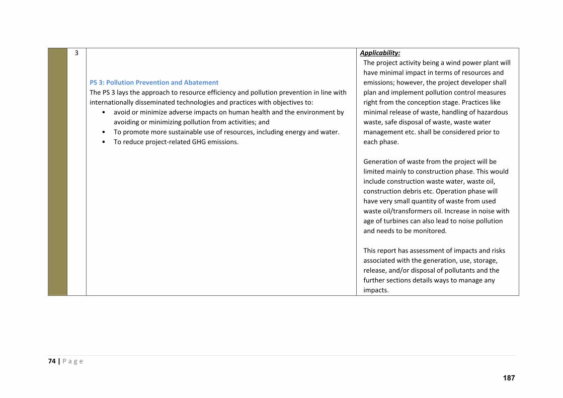
74 | P a g e
3
PS 3: Pollution Prevention and Abatement
The PS 3 lays the approach to resource efficiency and pollution prevention in line with
internationally disseminated technologies and practices with objectives to:
• avoid or minimize adverse impacts on human health and the environment by
avoiding or minimizing pollution from activities; and
• To promote more sustainable use of resources, including energy and water.
• To reduce project-related GHG emissions.
Applicability:
The project activity being a wind power plant will
have minimal impact in terms of resources and
emissions; however, the project developer shall
plan and implement pollution control measures
right from the conception stage. Practices like
minimal release of waste, handling of hazardous
waste, safe disposal of waste, waste water
management etc. shall be considered prior to
each phase.
Generation of waste from the project will be
limited mainly to construction phase. This would
include construction waste water, waste oil,
construction debris etc. Operation phase will
have very small quantity of waste from used
waste oil/transformers oil. Increase in noise with
age of turbines can also lead to noise pollution
and needs to be monitored.
This report has assessment of impacts and risks
associated with the generation, use, storage,
release, and/or disposal of pollutants and the
further sections details ways to manage any
impacts.
187
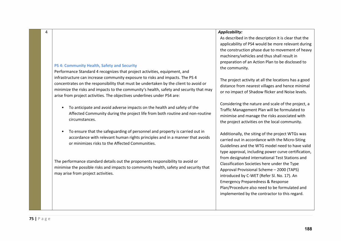
75 | P a g e
4
PS 4: Community Health, Safety and Security
Performance Standard 4 recognizes that project activities, equipment, and
infrastructure can increase community exposure to risks and impacts. The PS 4
concentrates on the responsibility that must be undertaken by the client to avoid or
i i ize the isks a d i pa ts to the o u it s health, safet a d se u it that a arise from project activities. The objectives underlines under PS4 are:
• To anticipate and avoid adverse impacts on the health and safety of the
Affected Community during the project life from both routine and non-routine
circumstances.
• To ensure that the safeguarding of personnel and property is carried out in
accordance with relevant human rights principles and in a manner that avoids
or minimizes risks to the Affected Communities.
The performance standard details out the proponents responsibility to avoid or
minimise the possible risks and impacts to community health, safety and security that
may arise from project activities.
Applicability:
As described in the description it is clear that the
applicability of PS4 would be more relevant during
the construction phase due to movement of heavy
machinery/vehicles and thus shall result in
preparation of an Action Plan to be disclosed to
the community.
The project activity at all the locations has a good
distance from nearest villages and hence minimal
or no impact of Shadow flicker and Noise levels.
Considering the nature and scale of the project, a
Traffic Management Plan will be formulated to
minimise and manage the risks associated with
the project activities on the local community.
Additionally, the siting of the project WTGs was
carried out in accordance with the Micro-Siting
Guidelines and the WTG model need to have valid
type approval, including power curve certification,
from designated international Test Stations and
Classification Societies here under the Type
Approval Provisional Scheme – 2000 (TAPS)
introduced by C-WET (Refer Sl. No. 17). An
Emergency Preparedness & Response
Plan/Procedure also need to be formulated and
implemented by the contractor to this regard.
188
76 | P a g e
5
PS 5: Land Acquisition and Involuntary Resettlement
The objectives of this PS are to:
• To avoid, and when avoidance is not possible, minimize displacement by
exploring alternative project designs.
• To avoid forced eviction.
• To anticipate and avoid, or where avoidance is not possible, minimize adverse
social and economic impacts from land acquisition or restrictions on land use
by (i) providing compensation for loss of assets at replacement cost and (ii)
ensuring that resettlement activities are implemented with appropriate
disclosure of information, consultation, and the informed participation of those
affected.
• To improve, or restore, the livelihoods and standards of living of displaced
persons.
• To improve living conditions among physically displaced persons through the
provision of adequate housing with security of tenure at resettlement sites.
Performance Standard 5 recognizes that project-related land acquisition and
restrictions on land use can have adverse impacts on communities and persons that use
this land. Involuntary resettlement refers both to physical displacement (relocation or
loss of shelter) and to economic displacement (loss of assets or access to assets that
leads to loss of income sources or other means of livelihood) as a result of project-
related land acquisition and/or restrictions on land use.
This PS does not apply to resettlement resulting from voluntary land transactions (i.e.,
market transactions in which the seller is not obliged to sell and the buyer cannot resort
to expropriation or other compulsory procedures if negotiations fail). The impacts
arising from such transactions shall be dealt with as under PS1, though sometimes,
when risks are identified, the project proponent may decide to adhere to PS 5
requirement even in willing buyer-seller cases.
Applicability:
All the project location fall under farming lands
which do not have any structures of settlements.
The land sellers interviewed had large portions of
land at their disposal and hence the project does
not attract any resettlement.
Moreover, the purchase of land for the proposed
project was through direct negotiations between
owners and land aggregators with no obligation
on the seller. There is no loss of assets or access
from the project. There will be no physical
resettlement and relocation of people as the
project area is not inhabited.
189
77 | P a g e
Resettlement is considered involuntary when affected persons or communities do not
have the right to refuse land acquisition or restrictions on land use that result in
physical or economic displacement.
6
PS 6: Biodiversity Conservation & Sustainable Natural Resources Management
Performance Standard 6 recognizes that protecting and conserving biodiversity,
maintaining ecosystem services, and sustainably managing living natural resources are
fundamental to sustainable development. The requirements set out in this
Performance Standard have been guided by the Convention on Biological Diversity,
hi h defi es iodi e sit as the a ia ilit a o g li i g o ga is s f om all sources
including, inter alia, terrestrial, marine and other aquatic ecosystems and the ecological
complexes of which they are a part; this includes diversity within species, between
spe ies, a d of e os ste s.
This Performance Standard addresses how clients can sustainably manage and mitigate
i pa ts o iodi e sit a d e os ste se i es th oughout the p oje t s life le.
• To protect and conserve biodiversity.
• To maintain the benefits from ecosystem services
• To promote the sustainable management of living natural resources through
the adoption of practices that integrate conservation needs and development
priorities
Applicability:
PS 6 is applicable to projects located in modified
natural, and critical habitats; or projects that
potentially impact or are dependent on ecosystem
services or that include the production of living
natural resources.
The proposed project is not located in close
proximity to any protected area. The ESIA study will
determine the significance of impacts on the
ecology of the project area.
The project area does not fall in any eco-sensitive
zones or critically endangered habitat.
The project can coexist with ecosystem with almost
no damage to living natural resources as the site
region is almost tree less. Due to lack of any air
emissions or liquid discharges during operation
phase, no adverse impacts to biodiversity or living
natural resources are anticipated.
The implementation of the actions necessary to
meet the requirements of PS6 shall be managed
through the suggested mitigation measures. The
operation phase of the proposed project shall
ensure protection of fauna and flora of the site and
190
78 | P a g e
the surrounding areas.
7 PS 7: Indigenous Peoples
Performance Standard 7 recognizes that Indigenous Peoples, as social groups with
identities that are distinct from mainstream groups in national societies, are often
among the most marginalized and vulnerable segments of the population. In many
cases, their economic, social, and legal status limits their capacity to defend their rights
to, and interests in, lands and natural and cultural resources, and may restrict their
ability to participate in and benefit from development. Indigenous Peoples are
particularly vulnerable if their lands and resources are transformed, encroached upon,
or significantly degraded. Their languages, cultures, religions, spiritual beliefs, and
institutions may also come under threat. As a consequence, Indigenous Peoples may be
more vulnerable to the adverse impacts associated with project development than
nonindigenous communities. This vulnerability may include loss of identity, culture, and
natural resource-based livelihoods, as well as exposure to impoverishment and
diseases.
The PS 7 highlights how Private sector projects can create opportunities for Indigenous
Peoples to participate in, and benefit from project related activities that may help them
fulfil their aspiration for economic and social development.
Applicability:
The project area or its surroundings does not
support indigenous communities like tribes, ethnic
minorities, aboriginals etc.
Scheduled Tribe (ST) population as classified by
Government of India do not qualify as indigenous
population, as per IFC PS -7, as ST have merged
with the mainstream population and share local
customs, traditions, social and legal structure. They
speak the same dialects and are equally dependent
on the surrounding natural resources as the
general population.
Moreover it is evident from the chapter 7 of this
report that the population of ST community in the
region is extremely limited and project has not
made any land purchase with the community so
far. In case of any land purchase from the
community, it will be ensured that the family find
employment in the project construction/operation.
Hence, the project does not anticipate any impact
to any indigenous population.
191
79 | P a g e
8 PS 8: Cultural Heritage
Performance Standard 8 recognizes the importance of cultural heritage for current and
future generations. Consistent with the Convention Concerning the Protection of the
World Cultural and Natural Heritage, this Performance Standard aims to ensure that
clients protect cultural heritage in the course of their project activities. In addition, the
re ui e e ts of this Pe fo a e “ta da d o a p oje t s use of ultu al he itage a e based in part on standards set by the Convention on Biological Diversity.
The two main objects as set out under PS 8 are:
To protect cultural heritage from the adverse impacts of project activities and support
its preservation
To promote the equitable sharing of benefits from the use of cultural heritage
Applicability:
PS 8 is applicable when tangible/intangible forms of
cultural heritage are impacted due the activities in
the project region.
The project study area has no cultural heritage
importance which can be impacted due to the
project. Hence, PS8 is not applicable for this
project.
192
80 | P a g e
4.5 Equator Principles (by the Equator Principles Financial Institutions)
The Equator Principles (EPs) is a risk management framework, adopted by financial institutions, for
determining, assessing and managing environmental and social risk in projects and is primarily
intended to provide a minimum standard for due diligence to support responsible risk decision-
making. The EP apply globally, to all industry sectors and to four financial products 1) Project Finance
Advisory Services 2) Project Finance 3) Project-Related Corporate Loans and 4) Bridge Loans.
Compliance with the Equator Principles (EP) is a requirement of many commercial banks for new
project financing with total capital costs of US$10 million or more3.
Currently 82 Equator Principles Financial Institutions (EPFIs) in 36 countries have officially adopted
the EPs, covering over 70 percent of international Project Finance debt in emerging markets.
There are a total 10 guidelines under the Equator Principles which are listed below:
1. Review and Categorisation
2. Social and Environmental Assessment
3. Applicable Environmental and Social standards
4. Environment and Social Management System and Equator Principles Action Plan
5. Stakeholder Engagement
6. Grievance Mechanism
7. Independent Review
8. Covenants
9. Independent Monitoring and Reporting
10. Reporting and Transparency
Principle 1: Review and Categorisation
When a project is proposed for financing, the EPFI will, as part of its internal social and
environmental review and due diligence, categorise such project based on the magnitude of its
potential impacts and risks in accordance with the environmental and social screening criteria of IFC.
Usi g atego isatio , the EPFI s e i o e tal a d so ial due dilige e is o e su ate with the
nature, scale and stage of the Project, and with the level of environmental and social risks and
impacts
Within the IFC, the wind project activity is a category B project – hi h i plies a p oje t ith potentially limited adverse environmental or social impacts that are few in number, generally site
spe ifi , la gel e e si le, a d eadil add essed th ough itigatio easu es .
Principle 2: Social and Environmental Assessment
3 http://www.equator-principles.com/resources/equator_principles_III.pdf
193
81 | P a g e
For all Category A and Category B Projects, the EPFI will require the client to conduct an Assessment
p o ess to add ess, to the EPFI s satisfa tio , the ele a t e i o e tal a d so ial isks a d impacts of the proposed Project. The Assessment Documentation should propose measures to
minimise, mitigate, and offset adverse impacts in a manner relevant and appropriate to the nature
and scale of the proposed Project.
The project activity has been assessed and assessment documentation is made comprehensively to
be adequate and accurate by doing objective evaluation and presentation of the environmental and
social risks and impacts.
Principle 3: Applicable Environmental and Social Standards
The Assessment process should, in the first instance, address compliance with relevant host country
laws, regulations and permits that pertain to environmental and social issues.
The EPFI will require that the Assessment process evaluates compliance with the applicable
standards as follows:
1) The Assessment process evaluates compliance with IFC PS and EHS Guideline
2) The Assessment process evaluates compliance with relevant host country laws, regulations
and permits that pertain to environmental and social issues.
The project activity has evaluated all the local National and international conventions, laws and
regulations applicable to the project activity. The details of same were presented in the previous
sections of the same chapter.
Principle 4: Environmental and Social Management System and Equator Principles Action Plan
For all Category A and Category B Projects, the EPFI will require the client to develop or maintain an
Environmental and Social Management System (ESMS).
Further, an Environmental and Social Management Plan (ESMP) will be prepared by the client to
address issues raised in the Assessment process and incorporate actions required to comply with the
appli a le sta da ds. Whe e the appli a le sta da ds a e ot et to the EPFI s satisfa tio , the client and the EPFI will agree an Equator Principles Action Plan (AP). The Equator Principles AP is
intended to outline gaps and commitments to meet EPFI requirements in line with the applicable
standards.
Hence, in accordance with the requirement of IFC PS and EP, an Environmental and Social
Management Plan has been drafted as a part of the ESIA study for the proposed project under the
chapter 9 of this report. The ESMP plan specifies appropriate plans and procedures which requires
to be implemented during various phases in order to prevent, control and mitigate any potential
environmental and social risks.
194
82 | P a g e
Principle 5: Stakeholder Engagement
For all Category A and Category B Projects, the EPFI will require the client to demonstrate effective
Stakeholder Engagement as an on-going process in a structured and culturally appropriate manner
with Affected Communities and, where relevant, Other Stakeholders.
The p oje t a ti it is atego ized u de Catego B , ith o pote tial ad e se i pa ts o the neighbouring Community. The project activity has undertaken social consultation at a household
level. The social consultation of the project involved consulting random houses and land seller and
nearby village representatives to establish the socio-economic condition of the area. This social
consultation also helped to understand any community concern that might be associated with the
proposed project, particularly related to loss of land, livelihood, resource requirement etc.
Taking into the factor laid in the principle the consultation meeting details are provided under the
chapter 6 of this report.
Principle 6: Grievance Mechanism
For all Category A and, as appropriate, Category B Projects, the EPFI will require the client, as part of
the ESMS, to establish a grievance mechanism designed to receive and facilitate resolution of
concerns and grievances about the Proje t s e i o e tal a d so ial pe fo a e.
The grievance mechanism is required to be scaled to the risks and impacts of the Project and have
Affected Communities as its primary user. It will seek to resolve concerns promptly, using an
understandable and transparent consultative process that is culturally appropriate, readily
accessible, at no cost, and without retribution to the party that originated the issue or concern.
Considering the requirement under this Principle, the project proponent has designed the CSR
programmes which maintain regular dialogue with communities through its activities in the project
region.
Principle 7: Independent Review
For all Category A and, as appropriate, Category B Projects, an Independent Environmental and
Social Consultant, not directly associated with the client, will carry out an Independent Review of the
Assessment Documentation including the ESMPs, the ESMS, and the Stakeholder Engagement
process documentation in order to assist the EPFI's due diligence, and assess Equator Principles
compliance.
The p oje t a ti it to get the o plia e of the p oje t s o plia e to the e ui e e t of E uato Principles.
195
83 | P a g e
Principle 8: Covenants
This guideline underlines the importance of incorporation of covenants linked to compliance.
For all Projects, the client will covenant in the financing documentation to comply with all relevant
host country environmental and social laws, regulations and permits in all material respects.
Furthermore for all Category A and Category B Projects, should to comply with the ESMPs and
Equator Principles AP, to provide periodic reports in a format agreed with the EPFI and at the time of
decommissioning, decommission the facilities, where applicable and appropriate, in accordance with
an agreed decommissioning plan.
The project to ensure communication with EP and convey their plans to EPFI. Where a client is not in
compliance with its environmental and social covenants, the EPFI will work with the client on
remedial actions to bring the Project back into compliance to the extent feasible.
Principle 9: Independent Monitoring and Reporting
To assess Project compliance with the Equator Principles and ensure on-going monitoring and
reporting after Financial Close and over the life of the loan, the EPFI will, for all Category A and, as
appropriate, Category B Projects, require the appointment of an Independent Environmental and
Social Consultant, or require that the client retain qualified and experienced external experts to
verify its monitoring information which would be shared with the EPFI.
The client to ensure that is engages with EPFI.
Principle 10: Reporting and Transparency
The following client reporting requirements are in addition to the disclosure requirements in
Principle 5.
For all Category A and, as appropriate, Category B Projects:
• The client will ensure that, at a minimum, a summary of the ESIA is accessible and available
online
• The client will publicly report GHG emission levels during the operational phase for Projects
emitting over 100,000 tonnes of CO2 equivalent annually.
The Client will make an extract of the ESIA summary to be available at the site office. Further the
project does not fall under the category of emissions over 1,00,000 tCO2. However, the project
emissions if any will be listed publically in the reports of CDM under Kyoto Protocol.
196
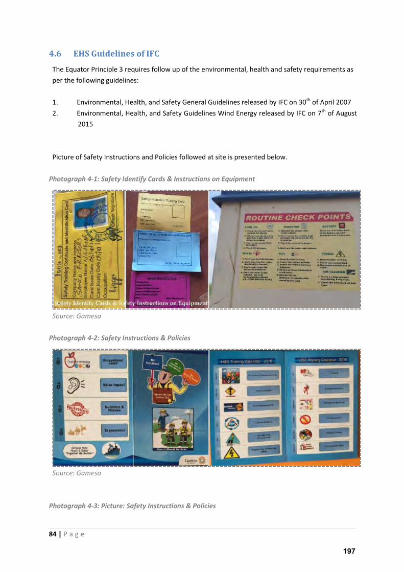
84 | P a g e
4.6 EHS Guidelines of IFC
The Equator Principle 3 requires follow up of the environmental, health and safety requirements as
per the following guidelines:
1. Environmental, Health, and Safety General Guidelines released by IFC on 30th of April 2007
2. Environmental, Health, and Safety Guidelines Wind Energy released by IFC on 7th of August
2015
Picture of Safety Instructions and Policies followed at site is presented below.
Photograph 4-1: Safety Identify Cards & Instructions on Equipment
Source: Gamesa
Photograph 4-2: Safety Instructions & Policies
Source: Gamesa
Photograph 4-3: Picture: Safety Instructions & Policies
197
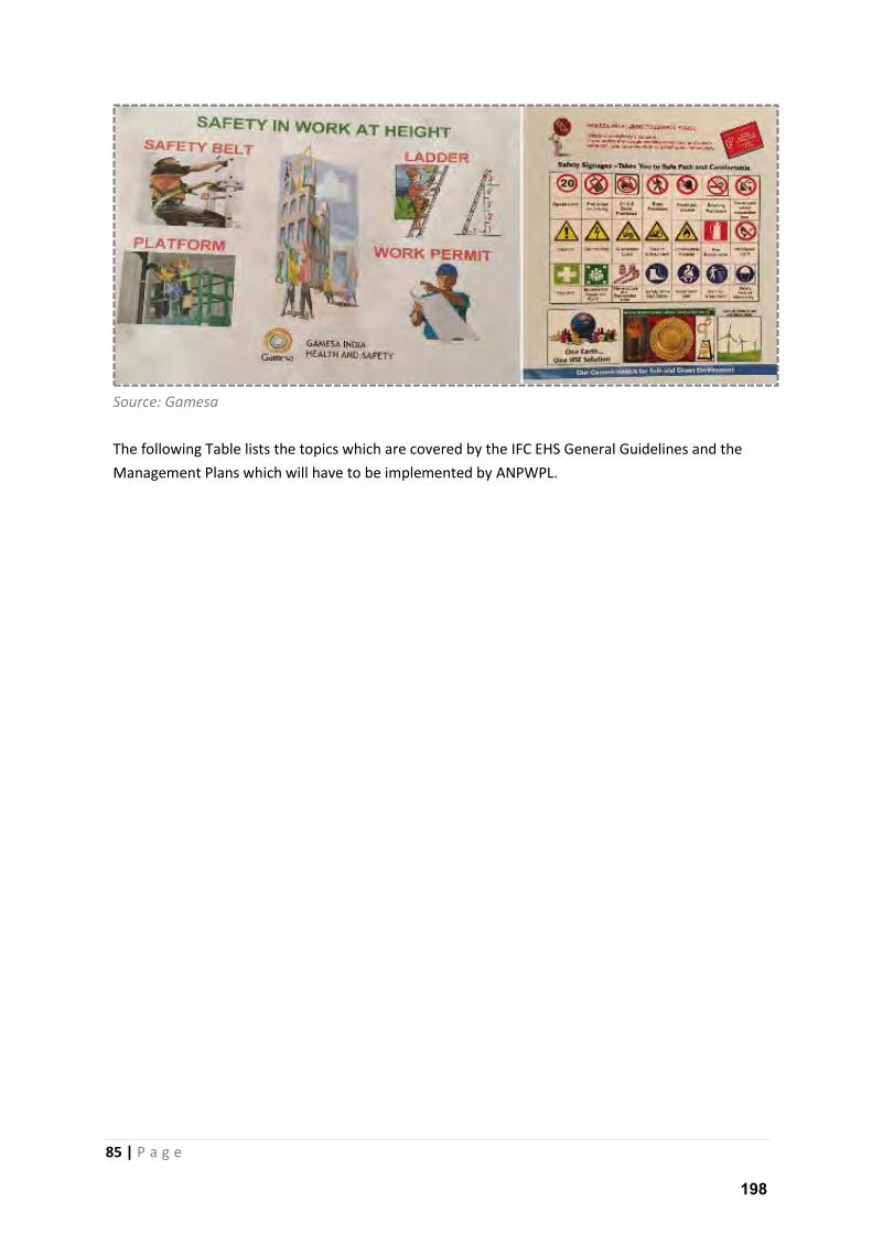
85 | P a g e
Source: Gamesa
The following Table lists the topics which are covered by the IFC EHS General Guidelines and the
Management Plans which will have to be implemented by ANPWPL.
198
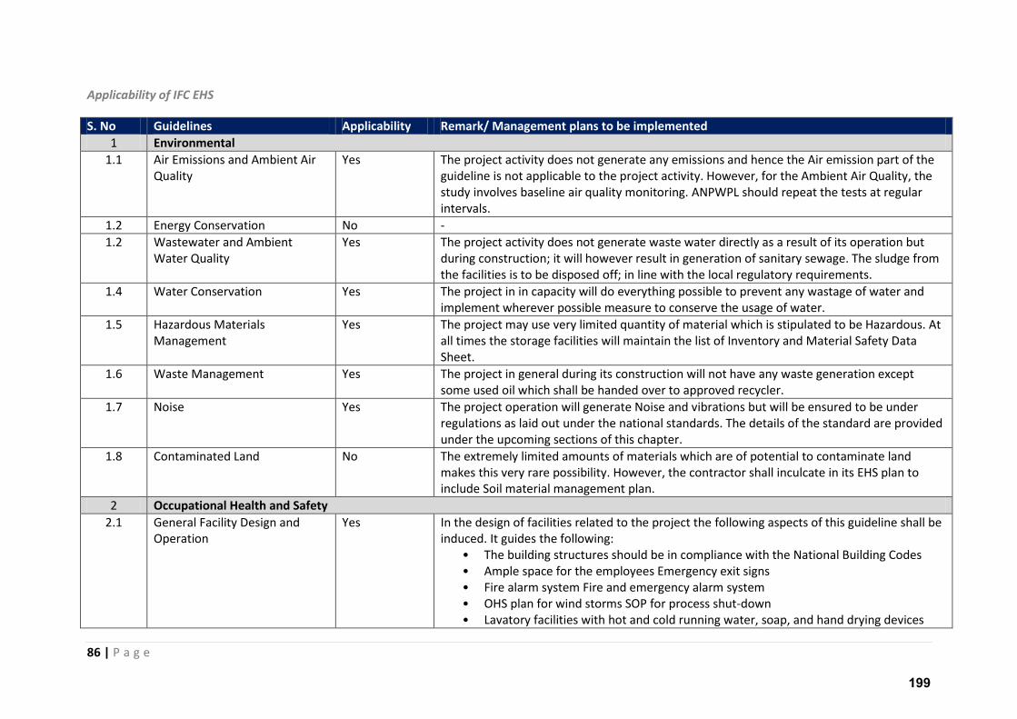
86 | P a g e
Applicability of IFC EHS
S. No Guidelines Applicability Remark/ Management plans to be implemented
1 Environmental
1.1 Air Emissions and Ambient Air
Quality
Yes The project activity does not generate any emissions and hence the Air emission part of the
guideline is not applicable to the project activity. However, for the Ambient Air Quality, the
study involves baseline air quality monitoring. ANPWPL should repeat the tests at regular
intervals.
1.2 Energy Conservation No -
1.2 Wastewater and Ambient
Water Quality
Yes The project activity does not generate waste water directly as a result of its operation but
during construction; it will however result in generation of sanitary sewage. The sludge from
the facilities is to be disposed off; in line with the local regulatory requirements.
1.4 Water Conservation Yes The project in in capacity will do everything possible to prevent any wastage of water and
implement wherever possible measure to conserve the usage of water.
1.5 Hazardous Materials
Management
Yes The project may use very limited quantity of material which is stipulated to be Hazardous. At
all times the storage facilities will maintain the list of Inventory and Material Safety Data
Sheet.
1.6 Waste Management Yes The project in general during its construction will not have any waste generation except
some used oil which shall be handed over to approved recycler.
1.7 Noise Yes The project operation will generate Noise and vibrations but will be ensured to be under
regulations as laid out under the national standards. The details of the standard are provided
under the upcoming sections of this chapter.
1.8 Contaminated Land No The extremely limited amounts of materials which are of potential to contaminate land
makes this very rare possibility. However, the contractor shall inculcate in its EHS plan to
include Soil material management plan.
2 Occupational Health and Safety
2.1 General Facility Design and
Operation
Yes In the design of facilities related to the project the following aspects of this guideline shall be
induced. It guides the following:
• The building structures should be in compliance with the National Building Codes
• Ample space for the employees Emergency exit signs
• Fire alarm system Fire and emergency alarm system
• OHS plan for wind storms SOP for process shut-down
• Lavatory facilities with hot and cold running water, soap, and hand drying devices
199
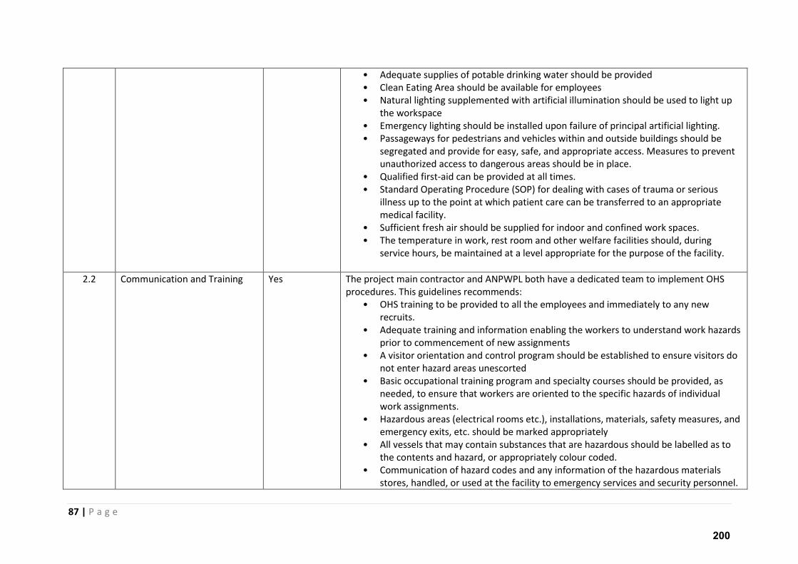
87 | P a g e
• Adequate supplies of potable drinking water should be provided
• Clean Eating Area should be available for employees
• Natural lighting supplemented with artificial illumination should be used to light up
the workspace
• Emergency lighting should be installed upon failure of principal artificial lighting.
• Passageways for pedestrians and vehicles within and outside buildings should be
segregated and provide for easy, safe, and appropriate access. Measures to prevent
unauthorized access to dangerous areas should be in place.
• Qualified first-aid can be provided at all times.
• Standard Operating Procedure (SOP) for dealing with cases of trauma or serious
illness up to the point at which patient care can be transferred to an appropriate
medical facility.
• Sufficient fresh air should be supplied for indoor and confined work spaces.
• The temperature in work, rest room and other welfare facilities should, during
service hours, be maintained at a level appropriate for the purpose of the facility.
2.2 Communication and Training Yes The project main contractor and ANPWPL both have a dedicated team to implement OHS
procedures. This guidelines recommends:
• OHS training to be provided to all the employees and immediately to any new
recruits.
• Adequate training and information enabling the workers to understand work hazards
prior to commencement of new assignments
• A visitor orientation and control program should be established to ensure visitors do
not enter hazard areas unescorted
• Basic occupational training program and specialty courses should be provided, as
needed, to ensure that workers are oriented to the specific hazards of individual
work assignments.
• Hazardous areas (electrical rooms etc.), installations, materials, safety measures, and
emergency exits, etc. should be marked appropriately
• All vessels that may contain substances that are hazardous should be labelled as to
the contents and hazard, or appropriately colour coded.
• Communication of hazard codes and any information of the hazardous materials
stores, handled, or used at the facility to emergency services and security personnel.
200
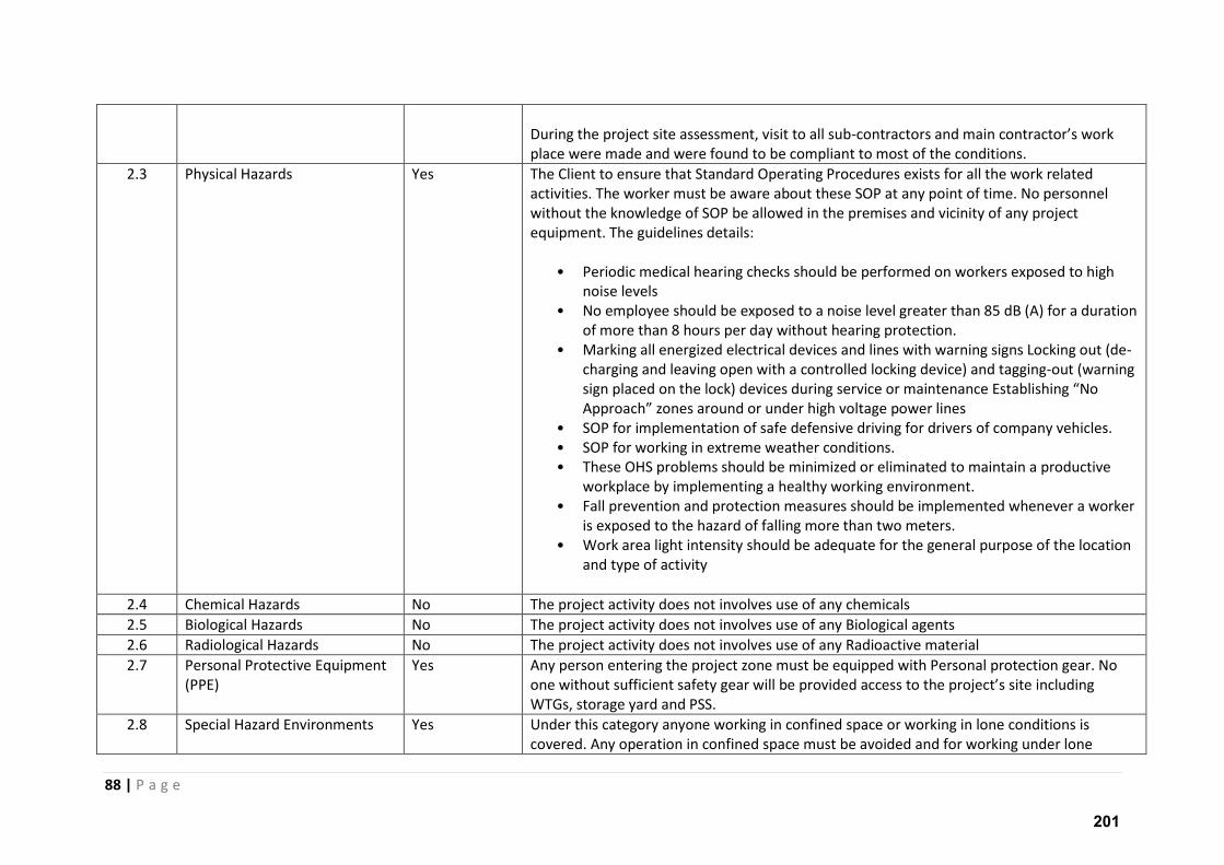
88 | P a g e
During the project site assessment, visit to all sub- o t a to s a d ai o t a to s o k place were made and were found to be compliant to most of the conditions.
2.3 Physical Hazards Yes The Client to ensure that Standard Operating Procedures exists for all the work related
activities. The worker must be aware about these SOP at any point of time. No personnel
without the knowledge of SOP be allowed in the premises and vicinity of any project
equipment. The guidelines details:
• Periodic medical hearing checks should be performed on workers exposed to high
noise levels
• No employee should be exposed to a noise level greater than 85 dB (A) for a duration
of more than 8 hours per day without hearing protection.
• Marking all energized electrical devices and lines with warning signs Locking out (de-
charging and leaving open with a controlled locking device) and tagging-out (warning
sig pla ed o the lo k de i es du i g se i e o ai te a e Esta lishi g No App oa h zo es a ou d o u de high oltage po e li es
• SOP for implementation of safe defensive driving for drivers of company vehicles.
• SOP for working in extreme weather conditions.
• These OHS problems should be minimized or eliminated to maintain a productive
workplace by implementing a healthy working environment.
• Fall prevention and protection measures should be implemented whenever a worker
is exposed to the hazard of falling more than two meters.
• Work area light intensity should be adequate for the general purpose of the location
and type of activity
2.4 Chemical Hazards No The project activity does not involves use of any chemicals
2.5 Biological Hazards No The project activity does not involves use of any Biological agents
2.6 Radiological Hazards No The project activity does not involves use of any Radioactive material
2.7 Personal Protective Equipment
(PPE)
Yes Any person entering the project zone must be equipped with Personal protection gear. No
o e ithout suffi ie t safet gea ill e p o ided a ess to the p oje t s site i ludi g WTGs, storage yard and PSS.
2.8 Special Hazard Environments Yes Under this category anyone working in confined space or working in lone conditions is
covered. Any operation in confined space must be avoided and for working under lone
201
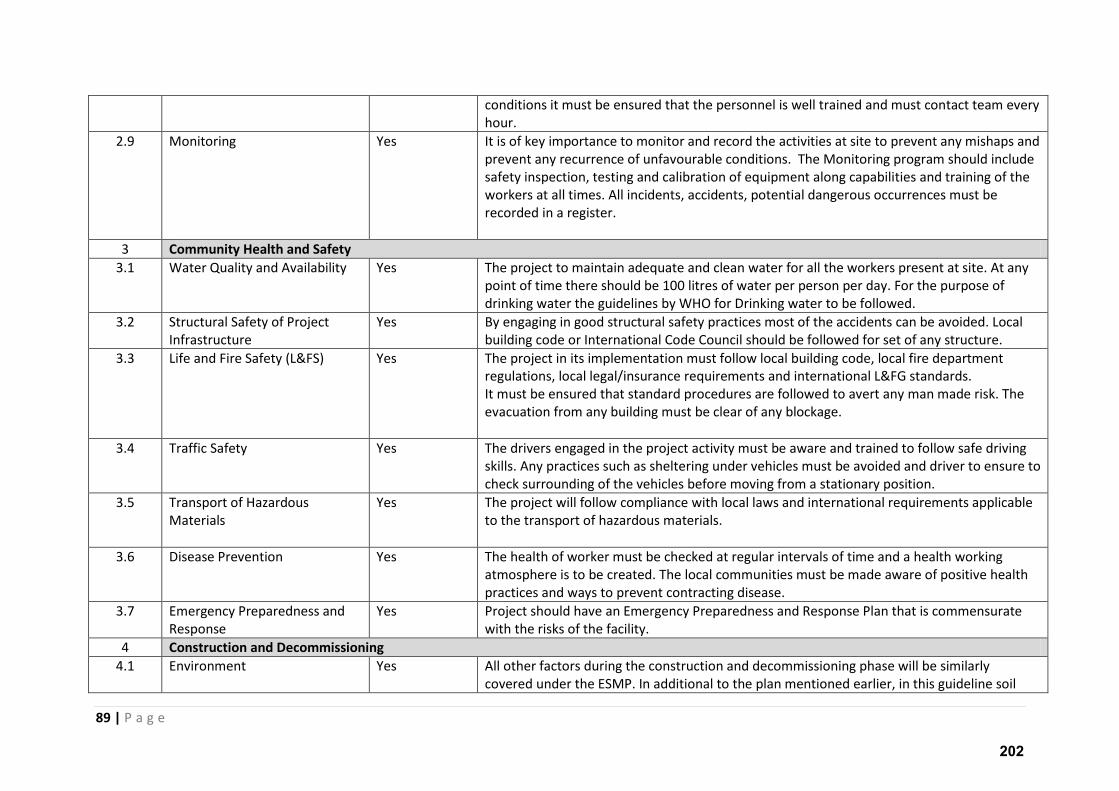
89 | P a g e
conditions it must be ensured that the personnel is well trained and must contact team every
hour.
2.9 Monitoring Yes It is of key importance to monitor and record the activities at site to prevent any mishaps and
prevent any recurrence of unfavourable conditions. The Monitoring program should include
safety inspection, testing and calibration of equipment along capabilities and training of the
workers at all times. All incidents, accidents, potential dangerous occurrences must be
recorded in a register.
3 Community Health and Safety
3.1 Water Quality and Availability Yes The project to maintain adequate and clean water for all the workers present at site. At any
point of time there should be 100 litres of water per person per day. For the purpose of
drinking water the guidelines by WHO for Drinking water to be followed.
3.2 Structural Safety of Project
Infrastructure
Yes By engaging in good structural safety practices most of the accidents can be avoided. Local
building code or International Code Council should be followed for set of any structure.
3.3 Life and Fire Safety (L&FS) Yes The project in its implementation must follow local building code, local fire department
regulations, local legal/insurance requirements and international L&FG standards.
It must be ensured that standard procedures are followed to avert any man made risk. The
evacuation from any building must be clear of any blockage.
3.4 Traffic Safety Yes The drivers engaged in the project activity must be aware and trained to follow safe driving
skills. Any practices such as sheltering under vehicles must be avoided and driver to ensure to
check surrounding of the vehicles before moving from a stationary position.
3.5 Transport of Hazardous
Materials
Yes The project will follow compliance with local laws and international requirements applicable
to the transport of hazardous materials.
3.6 Disease Prevention Yes The health of worker must be checked at regular intervals of time and a health working
atmosphere is to be created. The local communities must be made aware of positive health
practices and ways to prevent contracting disease.
3.7 Emergency Preparedness and
Response
Yes Project should have an Emergency Preparedness and Response Plan that is commensurate
with the risks of the facility.
4 Construction and Decommissioning
4.1 Environment Yes All other factors during the construction and decommissioning phase will be similarly
covered under the ESMP. In additional to the plan mentioned earlier, in this guideline soil
202
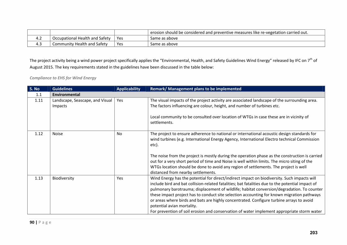
90 | P a g e
erosion should be considered and preventive measures like re-vegetation carried out.
4.2 Occupational Health and Safety Yes Same as above
4.3 Community Health and Safety Yes Same as above
The project activity being a wind power project specifi all applies the E i o e tal, Health, a d “afet Guideli es Wi d E e g eleased by IFC on 7th of
August 2015. The key requirements stated in the guidelines have been discussed in the table below:
Compliance to EHS for Wind Energy
S. No Guidelines Applicability Remark/ Management plans to be implemented
1.1 Environmental
1.11 Landscape, Seascape, and Visual
Impacts
Yes The visual impacts of the project activity are associated landscape of the surrounding area.
The factors influencing are colour, height, and number of turbines etc.
Local community to be consulted over location of WTGs in case these are in vicinity of
settlements.
1.12 Noise No The project to ensure adherence to national or international acoustic design standards for
wind turbines (e.g. International Energy Agency, International Electro technical Commission
etc).
The noise from the project is mostly during the operation phase as the construction is carried
out for a very short period of time and Noise is well within limits. The micro siting of the
WTGs location should be done to avoid any region of settlements. The project is well
distanced from nearby settlements.
1.13 Biodiversity Yes Wind Energy has the potential for direct/indirect impact on biodiversity. Such impacts will
include bird and bat collision-related fatalities; bat fatalities due to the potential impact of
pulmonary barotrauma; displacement of wildlife; habitat conversion/degradation. To counter
these impact project has to conduct site selection accounting for known migration pathways
or areas where birds and bats are highly concentrated. Configure turbine arrays to avoid
potential avian mortality.
For prevention of soil erosion and conservation of water implement appropriate storm water
203
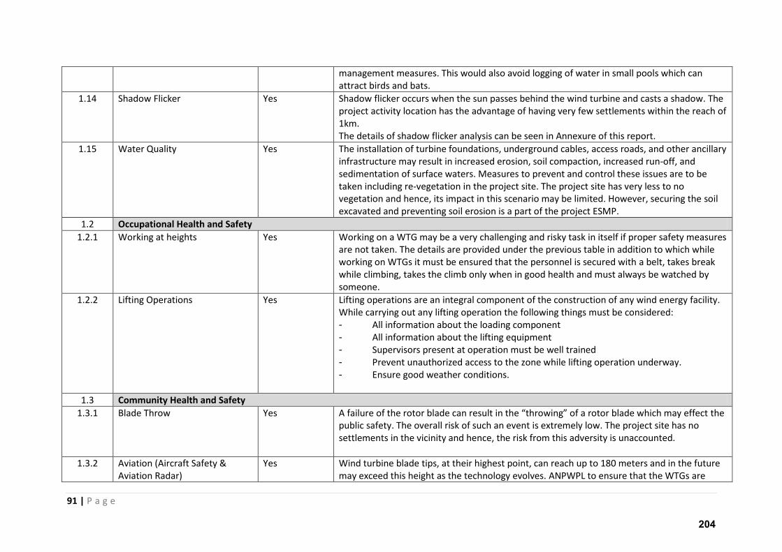
91 | P a g e
management measures. This would also avoid logging of water in small pools which can
attract birds and bats.
1.14 Shadow Flicker Yes Shadow flicker occurs when the sun passes behind the wind turbine and casts a shadow. The
project activity location has the advantage of having very few settlements within the reach of
1km.
The details of shadow flicker analysis can be seen in Annexure of this report.
1.15 Water Quality Yes The installation of turbine foundations, underground cables, access roads, and other ancillary
infrastructure may result in increased erosion, soil compaction, increased run-off, and
sedimentation of surface waters. Measures to prevent and control these issues are to be
taken including re-vegetation in the project site. The project site has very less to no
vegetation and hence, its impact in this scenario may be limited. However, securing the soil
excavated and preventing soil erosion is a part of the project ESMP.
1.2 Occupational Health and Safety
1.2.1 Working at heights
Yes Working on a WTG may be a very challenging and risky task in itself if proper safety measures
are not taken. The details are provided under the previous table in addition to which while
working on WTGs it must be ensured that the personnel is secured with a belt, takes break
while climbing, takes the climb only when in good health and must always be watched by
someone.
1.2.2 Lifting Operations Yes Lifting operations are an integral component of the construction of any wind energy facility.
While carrying out any lifting operation the following things must be considered:
- All information about the loading component
- All information about the lifting equipment
- Supervisors present at operation must be well trained
- Prevent unauthorized access to the zone while lifting operation underway.
- Ensure good weather conditions.
1.3 Community Health and Safety
1.3.1 Blade Throw Yes A failu e of the oto lade a esult i the th o i g of a oto lade hi h a effe t the
public safety. The overall risk of such an event is extremely low. The project site has no
settlements in the vicinity and hence, the risk from this adversity is unaccounted.
1.3.2 Aviation (Aircraft Safety &
Aviation Radar)
Yes Wind turbine blade tips, at their highest point, can reach up to 180 meters and in the future
may exceed this height as the technology evolves. ANPWPL to ensure that the WTGs are
204
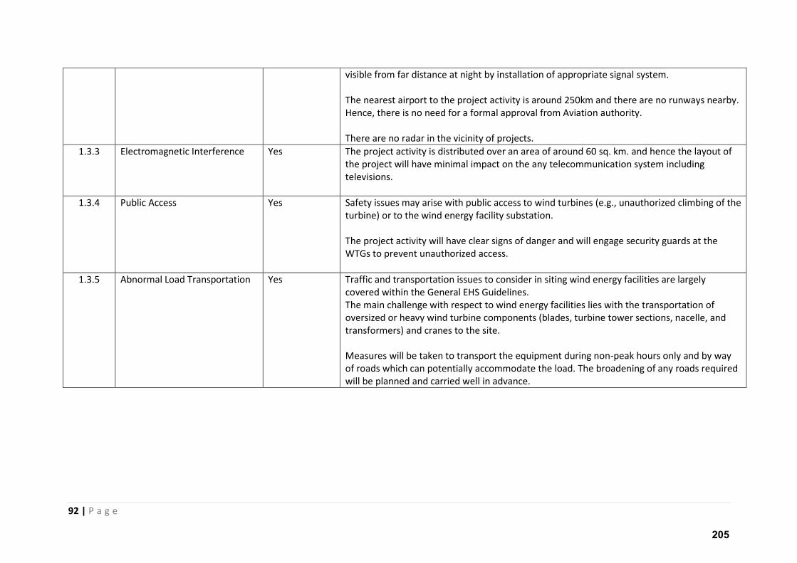
92 | P a g e
visible from far distance at night by installation of appropriate signal system.
The nearest airport to the project activity is around 250km and there are no runways nearby.
Hence, there is no need for a formal approval from Aviation authority.
There are no radar in the vicinity of projects.
1.3.3 Electromagnetic Interference Yes The project activity is distributed over an area of around 60 sq. km. and hence the layout of
the project will have minimal impact on the any telecommunication system including
televisions.
1.3.4 Public Access Yes Safety issues may arise with public access to wind turbines (e.g., unauthorized climbing of the
turbine) or to the wind energy facility substation.
The project activity will have clear signs of danger and will engage security guards at the
WTGs to prevent unauthorized access.
1.3.5 Abnormal Load Transportation
Yes Traffic and transportation issues to consider in siting wind energy facilities are largely
covered within the General EHS Guidelines.
The main challenge with respect to wind energy facilities lies with the transportation of
oversized or heavy wind turbine components (blades, turbine tower sections, nacelle, and
transformers) and cranes to the site.
Measures will be taken to transport the equipment during non-peak hours only and by way
of roads which can potentially accommodate the load. The broadening of any roads required
will be planned and carried well in advance.
205
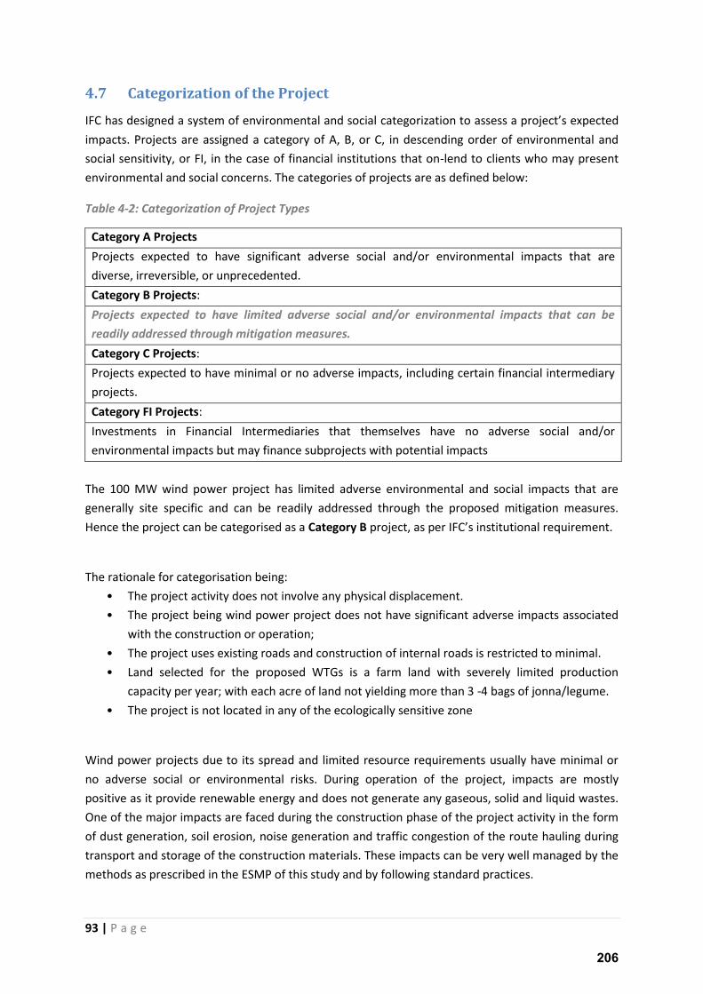
93 | P a g e
4.7 Categorization of the Project
IFC has designed a system of environmental and social atego izatio to assess a p oje t s e pe ted impacts. Projects are assigned a category of A, B, or C, in descending order of environmental and
social sensitivity, or FI, in the case of financial institutions that on-lend to clients who may present
environmental and social concerns. The categories of projects are as defined below:
Table 4-2: Categorization of Project Types
Category A Projects
Projects expected to have significant adverse social and/or environmental impacts that are
diverse, irreversible, or unprecedented.
Category B Projects:
Projects expected to have limited adverse social and/or environmental impacts that can be
readily addressed through mitigation measures.
Category C Projects:
Projects expected to have minimal or no adverse impacts, including certain financial intermediary
projects.
Category FI Projects:
Investments in Financial Intermediaries that themselves have no adverse social and/or
environmental impacts but may finance subprojects with potential impacts
The 100 MW wind power project has limited adverse environmental and social impacts that are
generally site specific and can be readily addressed through the proposed mitigation measures.
Hence the project can be categorised as a Category B project, as per IFC s i stitutio al e ui e e t.
The rationale for categorisation being:
• The project activity does not involve any physical displacement.
• The project being wind power project does not have significant adverse impacts associated
with the construction or operation;
• The project uses existing roads and construction of internal roads is restricted to minimal.
• Land selected for the proposed WTGs is a farm land with severely limited production
capacity per year; with each acre of land not yielding more than 3 -4 bags of jonna/legume.
• The project is not located in any of the ecologically sensitive zone
Wind power projects due to its spread and limited resource requirements usually have minimal or
no adverse social or environmental risks. During operation of the project, impacts are mostly
positive as it provide renewable energy and does not generate any gaseous, solid and liquid wastes.
One of the major impacts are faced during the construction phase of the project activity in the form
of dust generation, soil erosion, noise generation and traffic congestion of the route hauling during
transport and storage of the construction materials. These impacts can be very well managed by the
methods as prescribed in the ESMP of this study and by following standard practices.
206
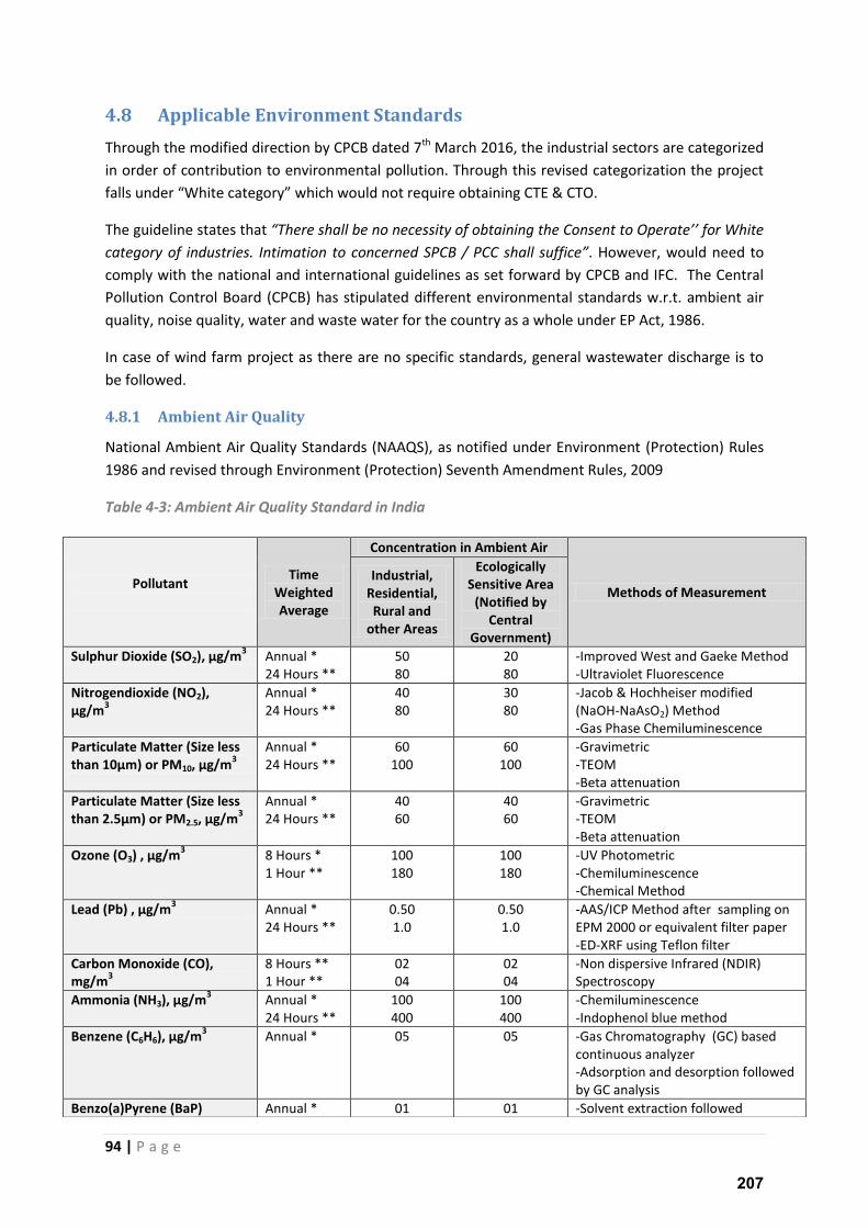
94 | P a g e
4.8 Applicable Environment Standards
Through the modified direction by CPCB dated 7th March 2016, the industrial sectors are categorized
in order of contribution to environmental pollution. Through this revised categorization the project
falls under White category which would not require obtaining CTE & CTO.
The guideline states that There shall e o e essit of o tai i g the Co se t to Operate for White category of industries. Intimation to concerned SPCB / PCC shall suffice . However, would need to
comply with the national and international guidelines as set forward by CPCB and IFC. The Central
Pollution Control Board (CPCB) has stipulated different environmental standards w.r.t. ambient air
quality, noise quality, water and waste water for the country as a whole under EP Act, 1986.
In case of wind farm project as there are no specific standards, general wastewater discharge is to
be followed.
4.8.1 Ambient Air Quality
National Ambient Air Quality Standards (NAAQS), as notified under Environment (Protection) Rules
1986 and revised through Environment (Protection) Seventh Amendment Rules, 2009
Table 4-3: Ambient Air Quality Standard in India
Pollutant
Time
Weighted
Average
Concentration in Ambient Air
Methods of Measurement
Industrial,
Residential,
Rural and
other Areas
Ecologically
Sensitive Area
(Notified by
Central
Government)
Sulphur Dioxide (SO2), µg/m3 Annual *
24 Hours **
50
80
20
80
-Improved West and Gaeke Method
-Ultraviolet Fluorescence
Nitrogendioxide (NO2),
µg/m3
Annual *
24 Hours **
40
80
30
80
-Jacob & Hochheiser modified
(NaOH-NaAsO2) Method
-Gas Phase Chemiluminescence
Particulate Matter (Size less
than 10µm) or PM10, µg/m3
Annual *
24 Hours **
60
100
60
100
-Gravimetric
-TEOM
-Beta attenuation
Particulate Matter (Size less
than 2.5µm) or PM2.5, µg/m3
Annual *
24 Hours **
40
60
40
60
-Gravimetric
-TEOM
-Beta attenuation
Ozone (O3) , µg/m3 8 Hours *
1 Hour **
100
180
100
180
-UV Photometric
-Chemiluminescence
-Chemical Method
Lead (Pb) , µg/m3 Annual *
24 Hours **
0.50
1.0
0.50
1.0
-AAS/ICP Method after sampling on
EPM 2000 or equivalent filter paper
-ED-XRF using Teflon filter
Carbon Monoxide (CO),
mg/m3
8 Hours **
1 Hour **
02
04
02
04
-Non dispersive Infrared (NDIR)
Spectroscopy
Ammonia (NH3), µg/m3 Annual *
24 Hours **
100
400
100
400
-Chemiluminescence
-Indophenol blue method
Benzene (C6H6), µg/m3 Annual *
05 05 -Gas Chromatography (GC) based
continuous analyzer
-Adsorption and desorption followed
by GC analysis
Benzo(a)Pyrene (BaP) Annual * 01 01 -Solvent extraction followed
207
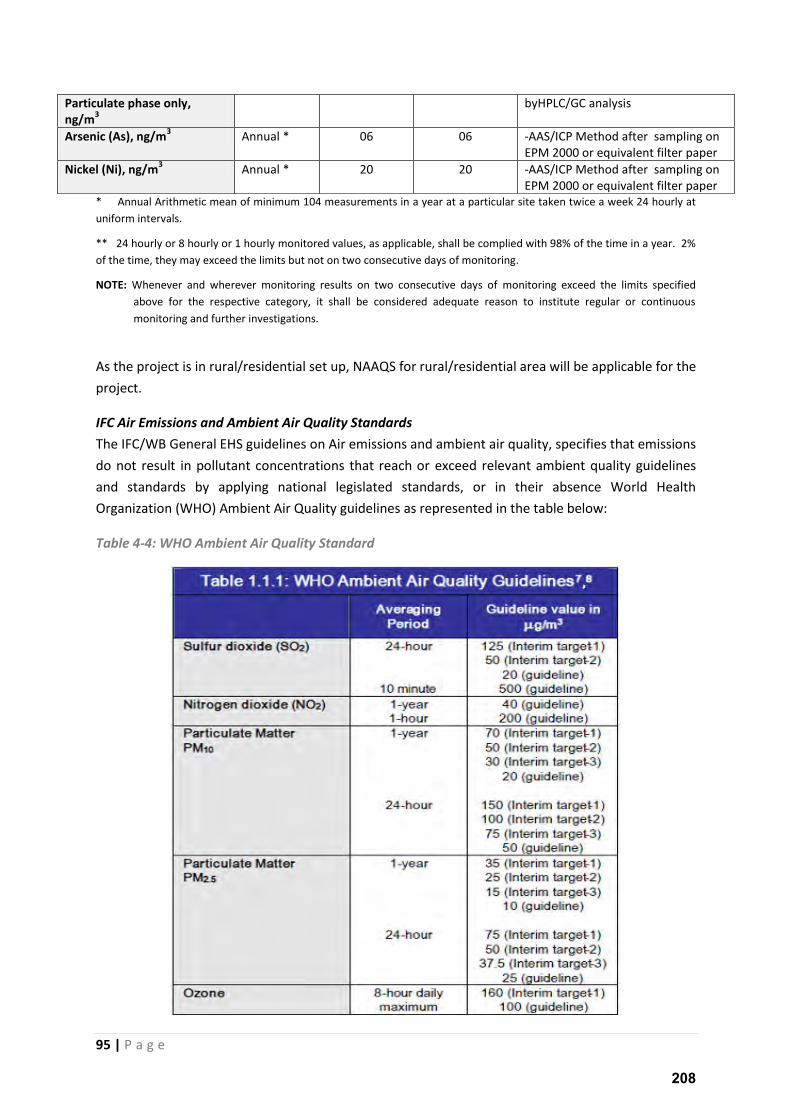
95 | P a g e
* Annual Arithmetic mean of minimum 104 measurements in a year at a particular site taken twice a week 24 hourly at
uniform intervals.
** 24 hourly or 8 hourly or 1 hourly monitored values, as applicable, shall be complied with 98% of the time in a year. 2%
of the time, they may exceed the limits but not on two consecutive days of monitoring.
NOTE: Whenever and wherever monitoring results on two consecutive days of monitoring exceed the limits specified
above for the respective category, it shall be considered adequate reason to institute regular or continuous
monitoring and further investigations.
As the project is in rural/residential set up, NAAQS for rural/residential area will be applicable for the
project.
IFC Air Emissions and Ambient Air Quality Standards
The IFC/WB General EHS guidelines on Air emissions and ambient air quality, specifies that emissions
do not result in pollutant concentrations that reach or exceed relevant ambient quality guidelines
and standards by applying national legislated standards, or in their absence World Health
Organization (WHO) Ambient Air Quality guidelines as represented in the table below:
Table 4-4: WHO Ambient Air Quality Standard
Particulate phase only,
ng/m3
byHPLC/GC analysis
Arsenic (As), ng/m3 Annual *
06 06 -AAS/ICP Method after sampling on
EPM 2000 or equivalent filter paper
Nickel (Ni), ng/m3 Annual *
20 20 -AAS/ICP Method after sampling on
EPM 2000 or equivalent filter paper
208
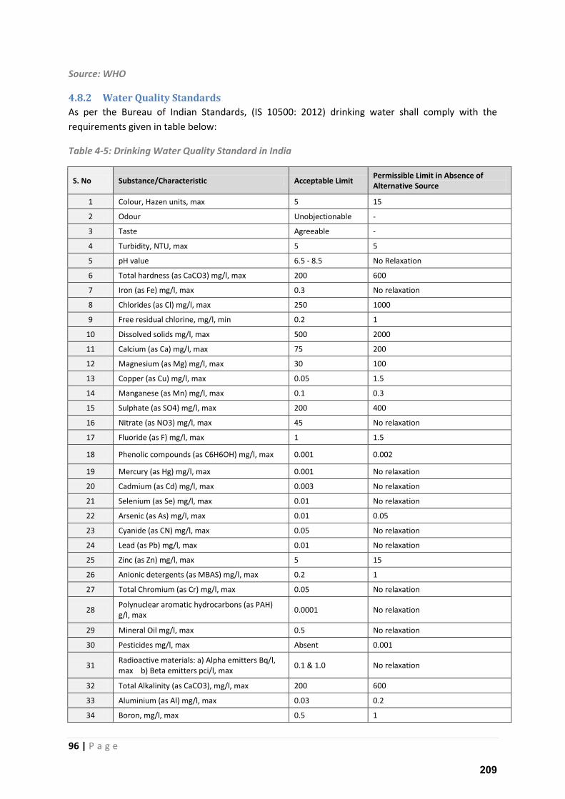
96 | P a g e
Source: WHO
4.8.2 Water Quality Standards
As per the Bureau of Indian Standards, (IS 10500: 2012) drinking water shall comply with the
requirements given in table below:
Table 4-5: Drinking Water Quality Standard in India
S. No Substance/Characteristic Acceptable Limit Permissible Limit in Absence of
Alternative Source
1 Colour, Hazen units, max 5 15
2 Odour Unobjectionable -
3 Taste Agreeable -
4 Turbidity, NTU, max 5 5
5 pH value 6.5 - 8.5 No Relaxation
6 Total hardness (as CaCO3) mg/l, max 200 600
7 Iron (as Fe) mg/l, max 0.3 No relaxation
8 Chlorides (as Cl) mg/l, max 250 1000
9 Free residual chlorine, mg/l, min 0.2 1
10 Dissolved solids mg/l, max 500 2000
11 Calcium (as Ca) mg/l, max 75 200
12 Magnesium (as Mg) mg/l, max 30 100
13 Copper (as Cu) mg/l, max 0.05 1.5
14 Manganese (as Mn) mg/l, max 0.1 0.3
15 Sulphate (as SO4) mg/l, max 200 400
16 Nitrate (as NO3) mg/l, max 45 No relaxation
17 Fluoride (as F) mg/l, max 1 1.5
18 Phenolic compounds (as C6H6OH) mg/l, max 0.001 0.002
19 Mercury (as Hg) mg/l, max 0.001 No relaxation
20 Cadmium (as Cd) mg/l, max 0.003 No relaxation
21 Selenium (as Se) mg/l, max 0.01 No relaxation
22 Arsenic (as As) mg/l, max 0.01 0.05
23 Cyanide (as CN) mg/l, max 0.05 No relaxation
24 Lead (as Pb) mg/l, max 0.01 No relaxation
25 Zinc (as Zn) mg/l, max 5 15
26 Anionic detergents (as MBAS) mg/l, max 0.2 1
27 Total Chromium (as Cr) mg/l, max 0.05 No relaxation
28 Polynuclear aromatic hydrocarbons (as PAH)
g/l, max 0.0001 No relaxation
29 Mineral Oil mg/l, max 0.5 No relaxation
30 Pesticides mg/l, max Absent 0.001
31 Radioactive materials: a) Alpha emitters Bq/l,
max b) Beta emitters pci/l, max 0.1 & 1.0 No relaxation
32 Total Alkalinity (as CaCO3), mg/l, max 200 600
33 Aluminium (as Al) mg/l, max 0.03 0.2
34 Boron, mg/l, max 0.5 1
209
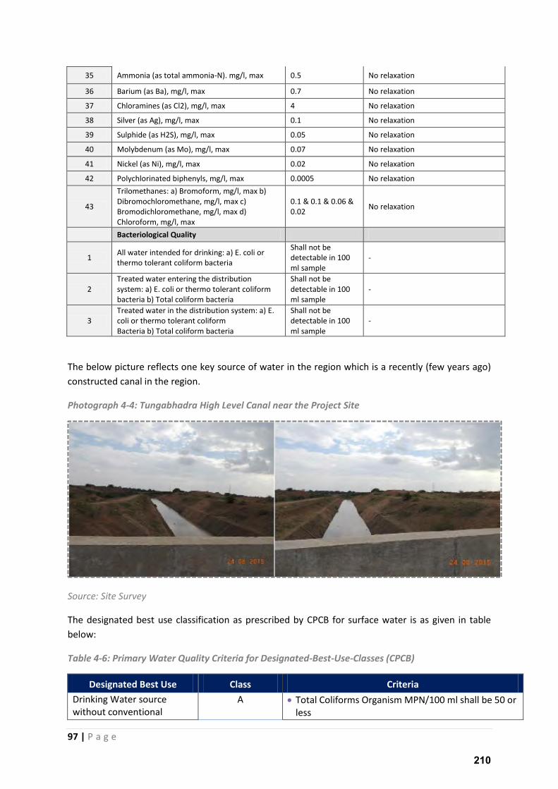
97 | P a g e
35 Ammonia (as total ammonia-N). mg/l, max 0.5 No relaxation
36 Barium (as Ba), mg/l, max 0.7 No relaxation
37 Chloramines (as Cl2), mg/l, max 4 No relaxation
38 Silver (as Ag), mg/l, max 0.1 No relaxation
39 Sulphide (as H2S), mg/l, max 0.05 No relaxation
40 Molybdenum (as Mo), mg/l, max 0.07 No relaxation
41 Nickel (as Ni), mg/l, max 0.02 No relaxation
42 Polychlorinated biphenyls, mg/l, max 0.0005 No relaxation
43
Trilomethanes: a) Bromoform, mg/l, max b)
Dibromochloromethane, mg/l, max c)
Bromodichloromethane, mg/l, max d)
Chloroform, mg/l, max
0.1 & 0.1 & 0.06 &
0.02 No relaxation
Bacteriological Quality
1 All water intended for drinking: a) E. coli or
thermo tolerant coliform bacteria
Shall not be
detectable in 100
ml sample
-
2
Treated water entering the distribution
system: a) E. coli or thermo tolerant coliform
bacteria b) Total coliform bacteria
Shall not be
detectable in 100
ml sample
-
3
Treated water in the distribution system: a) E.
coli or thermo tolerant coliform
Bacteria b) Total coliform bacteria
Shall not be
detectable in 100
ml sample
-
The below picture reflects one key source of water in the region which is a recently (few years ago)
constructed canal in the region.
Photograph 4-4: Tungabhadra High Level Canal near the Project Site
Source: Site Survey
The designated best use classification as prescribed by CPCB for surface water is as given in table
below:
Table 4-6: Primary Water Quality Criteria for Designated-Best-Use-Classes (CPCB)
Designated Best Use Class Criteria
Drinking Water source
without conventional
A Total Coliforms Organism MPN/100 ml shall be 50 or
less
210
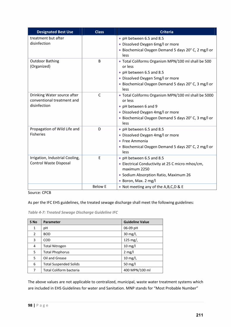
98 | P a g e
Designated Best Use Class Criteria
treatment but after
disinfection
pH between 6.5 and 8.5
Dissolved Oxygen 6mg/l or more
Biochemical Oxygen Demand 5 days 20° C, 2 mg/l or
less
Outdoor Bathing
(Organized)
B Total Coliforms Organism MPN/100 ml shall be 500
or less
pH between 6.5 and 8.5
Dissolved Oxygen 5mg/l or more
Biochemical Oxygen Demand 5 days 20° C, 3 mg/l or
less
Drinking Water source after
conventional treatment and
disinfection
C Total Coliforms Organism MPN/100 ml shall be 5000
or less
pH between 6 and 9
Dissolved Oxygen 4mg/l or more
Biochemical Oxygen Demand 5 days 20° C, 3 mg/l or
less
Propagation of Wild Life and
Fisheries
D pH between 6.5 and 8.5
Dissolved Oxygen 4mg/l or more
Free Ammonia
Biochemical Oxygen Demand 5 days 20° C, 2 mg/l or
less
Irrigation, Industrial Cooling,
Control Waste Disposal
E pH between 6.5 and 8.5
Electrical Conductivity at 25 C micro mhos/cm,
maximum 2250
Sodium Absorption Ratio, Maximum 26
Boron, Max. 2 mg/l
Below E Not meeting any of the A,B,C,D & E
Source: CPCB
As per the IFC EHS guidelines, the treated sewage discharge shall meet the following guidelines:
Table 4-7: Treated Sewage Discharge Guideline IFC
S No Parameter Guideline Value
1 pH 06-09 pH
2 BOD 30 mg/l,
3 COD 125 mg/,
4 Total Nitrogen 10 mg/l
5 Total Phophorus 2 mg/l
5 Oil and Grease 10 mg/l,
6 Total Suspended Solids 50 mg/l
7 Total Coliform bacteria 400 MPN/100 ml
The above values are not applicable to centralized, municipal, waste water treatment systems which
a e i luded i EH“ Guideli es fo ate a d “a itatio . MNP sta ds fo Most P o a le Nu e
211
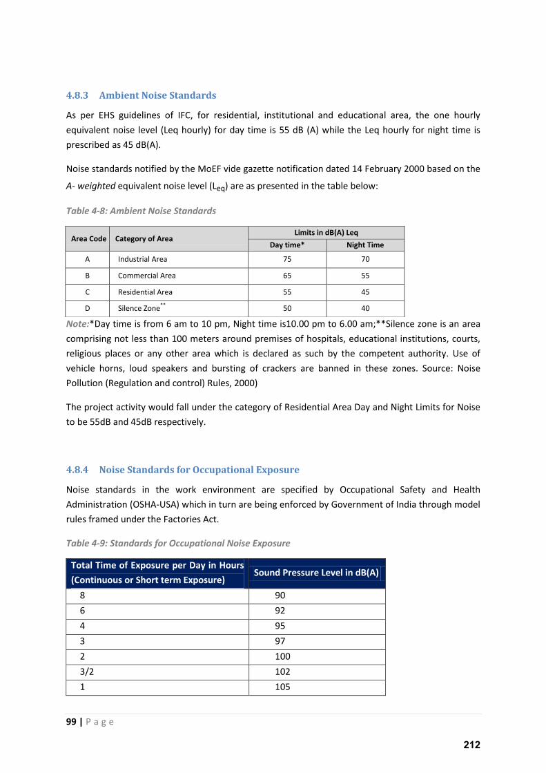
99 | P a g e
4.8.3 Ambient Noise Standards
As per EHS guidelines of IFC, for residential, institutional and educational area, the one hourly
equivalent noise level (Leq hourly) for day time is 55 dB (A) while the Leq hourly for night time is
prescribed as 45 dB(A).
Noise standards notified by the MoEF vide gazette notification dated 14 February 2000 based on the
A- weighted equivalent noise level (Leq) are as presented in the table below:
Table 4-8: Ambient Noise Standards
Note:*Day time is from 6 am to 10 pm, Night time is10.00 pm to 6.00 am;**Silence zone is an area
comprising not less than 100 meters around premises of hospitals, educational institutions, courts,
religious places or any other area which is declared as such by the competent authority. Use of
vehicle horns, loud speakers and bursting of crackers are banned in these zones. Source: Noise
Pollution (Regulation and control) Rules, 2000)
The project activity would fall under the category of Residential Area Day and Night Limits for Noise
to be 55dB and 45dB respectively.
4.8.4 Noise Standards for Occupational Exposure
Noise standards in the work environment are specified by Occupational Safety and Health
Administration (OSHA-USA) which in turn are being enforced by Government of India through model
rules framed under the Factories Act.
Table 4-9: Standards for Occupational Noise Exposure
Total Time of Exposure per Day in Hours
(Continuous or Short term Exposure) Sound Pressure Level in dB(A)
8 90
6 92
4 95
3 97
2 100
3/2 102
1 105
Area Code Category of Area Limits in dB(A) Leq
Day time* Night Time
A Industrial Area 75 70
B Commercial Area 65 55
C Residential Area 55 45
D Silence Zone**
50 40
212

100 | P a g e
¾ 107
½ 110
¼ 115
Never >115
• No exposure in excess of 115 dB(A) is to be permitted.
• For any period of exposure falling in between any figure and the next higher or lower figure
as indicated in column (1), the permissible level is to be determined by extrapolation on a
proportionate scale.
213
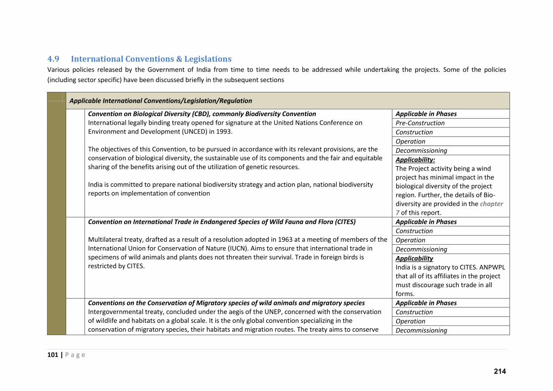
101 | P a g e
4.9 International Conventions & Legislations
Various policies released by the Government of India from time to time needs to be addressed while undertaking the projects. Some of the policies
(including sector specific) have been discussed briefly in the subsequent sections
Applicable International Conventions/Legislation/Regulation
Convention on Biological Diversity (CBD), commonly Biodiversity Convention
International legally binding treaty opened for signature at the United Nations Conference on
Environment and Development (UNCED) in 1993.
The objectives of this Convention, to be pursued in accordance with its relevant provisions, are the
conservation of biological diversity, the sustainable use of its components and the fair and equitable
sharing of the benefits arising out of the utilization of genetic resources.
India is committed to prepare national biodiversity strategy and action plan, national biodiversity
reports on implementation of convention
Applicable in Phases
Pre-Construction
Construction
Operation
Decommissioning
Applicability:
The Project activity being a wind
project has minimal impact in the
biological diversity of the project
region. Further, the details of Bio-
diversity are provided in the chapter
7 of this report.
Convention on International Trade in Endangered Species of Wild Fauna and Flora (CITES)
Multilateral treaty, drafted as a result of a resolution adopted in 1963 at a meeting of members of the
International Union for Conservation of Nature (IUCN). Aims to ensure that international trade in
specimens of wild animals and plants does not threaten their survival. Trade in foreign birds is
restricted by CITES.
Applicable in Phases
Construction
Operation
Decommissioning
Applicability
India is a signatory to CITES. ANPWPL
that all of its affiliates in the project
must discourage such trade in all
forms.
Conventions on the Conservation of Migratory species of wild animals and migratory species
Intergovernmental treaty, concluded under the aegis of the UNEP, concerned with the conservation
of wildlife and habitats on a global scale. It is the only global convention specializing in the
conservation of migratory species, their habitats and migration routes. The treaty aims to conserve
Applicable in Phases
Construction
Operation
Decommissioning
214
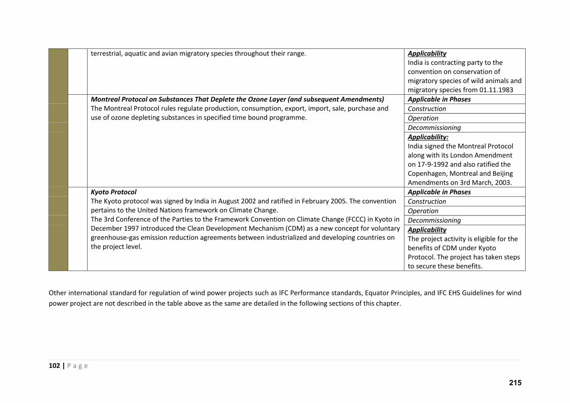
102 | P a g e
terrestrial, aquatic and avian migratory species throughout their range. Applicability
India is contracting party to the
convention on conservation of
migratory species of wild animals and
migratory species from 01.11.1983
Montreal Protocol on Substances That Deplete the Ozone Layer (and subsequent Amendments)
The Montreal Protocol rules regulate production, consumption, export, import, sale, purchase and
use of ozone depleting substances in specified time bound programme.
Applicable in Phases
Construction
Operation
Decommissioning
Applicability:
India signed the Montreal Protocol
along with its London Amendment
on 17-9-1992 and also ratified the
Copenhagen, Montreal and Beijing
Amendments on 3rd March, 2003.
Kyoto Protocol
The Kyoto protocol was signed by India in August 2002 and ratified in February 2005. The convention
pertains to the United Nations framework on Climate Change.
The 3rd Conference of the Parties to the Framework Convention on Climate Change (FCCC) in Kyoto in
December 1997 introduced the Clean Development Mechanism (CDM) as a new concept for voluntary
greenhouse-gas emission reduction agreements between industrialized and developing countries on
the project level.
Applicable in Phases
Construction
Operation
Decommissioning
Applicability
The project activity is eligible for the
benefits of CDM under Kyoto
Protocol. The project has taken steps
to secure these benefits.
Other international standard for regulation of wind power projects such as IFC Performance standards, Equator Principles, and IFC EHS Guidelines for wind
power project are not described in the table above as the same are detailed in the following sections of this chapter.
215
103 | P a g e
5 ANALYSIS OF ALTERNATIVES
The alternatives analysis for the wind project as a standard includes analysis of project existence,
location, technology and evacuation plan. An analysis of alternatives for the proposed wind power
project is discussed in the following section. The variables as described are chosen to be:
Project vs No Project Scenario;
Alternate location for the proposed Project ;
Alternate methods of power generation; and
Alternate routes to transmission lines.
5.1 No Project Scenario;
It is a hypothetical scenario where the project would not have been conceived. It is interesting to
note that India to fuel is economy and growth needs more power than ever before.
India is a developing country with significant shortage of electricity. Hence, a scenario where the
project is not conceived is an unfavourable scenario.
Currently, as of February 2016 India has a total installed capacity of 288,005 MW (Central Electricty
Authority4) of which only 38,821 MW is renewable energy. The major (200,740MW) of the installed
capacity comes from very old and inefficient Coal, Oil & Gas power projects. Currently, in India,
emissions associated with generation of each MW of electricity is in the range of 950kg of CO2.
Hence, it is clear that our national power generation is highly carbon intensive and India must focus
on a shift towards renewable energy to help mitigate climate change. There is no better alternative
than implementation of renewable power projects. The power mix in India is presented in the
following table.
Figure 5-1: Power Generation Technologies share in India
4 http://www.cea.nic.in/reports/monthly/executivesummary/2016/exe_summary-01.pdf
216
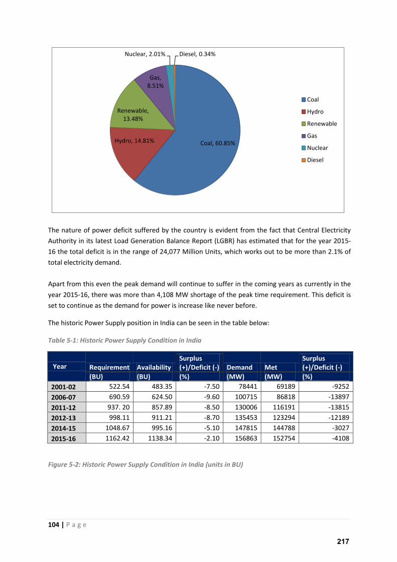
104 | P a g e
The nature of power deficit suffered by the country is evident from the fact that Central Electricity
Authority in its latest Load Generation Balance Report (LGBR) has estimated that for the year 2015-
16 the total deficit is in the range of 24,077 Million Units, which works out to be more than 2.1% of
total electricity demand.
Apart from this even the peak demand will continue to suffer in the coming years as currently in the
year 2015-16, there was more than 4,108 MW shortage of the peak time requirement. This deficit is
set to continue as the demand for power is increase like never before.
The historic Power Supply position in India can be seen in the table below:
Table 5-1: Historic Power Supply Condition in India
Year Requirement Availability
Surplus
(+)/Deficit (-) Demand Met
Surplus
(+)/Deficit (-)
(BU) (BU) (%) (MW) (MW) (%)
2001-02 522.54 483.35 -7.50 78441 69189 -9252
2006-07 690.59 624.50 -9.60 100715 86818 -13897
2011-12 937. 20 857.89 -8.50 130006 116191 -13815
2012-13 998.11 911.21 -8.70 135453 123294 -12189
2014-15 1048.67 995.16 -5.10 147815 144788 -3027
2015-16 1162.42 1138.34 -2.10 156863 152754 -4108
Figure 5-2: Historic Power Supply Condition in India (units in BU)
Coal, 60.85% Hydro, 14.81%
Renewable,
13.48%
Gas,
8.51%
Nuclear, 2.01% Diesel, 0.34%
Coal
Hydro
Renewable
Gas
Nuclear
Diesel
217
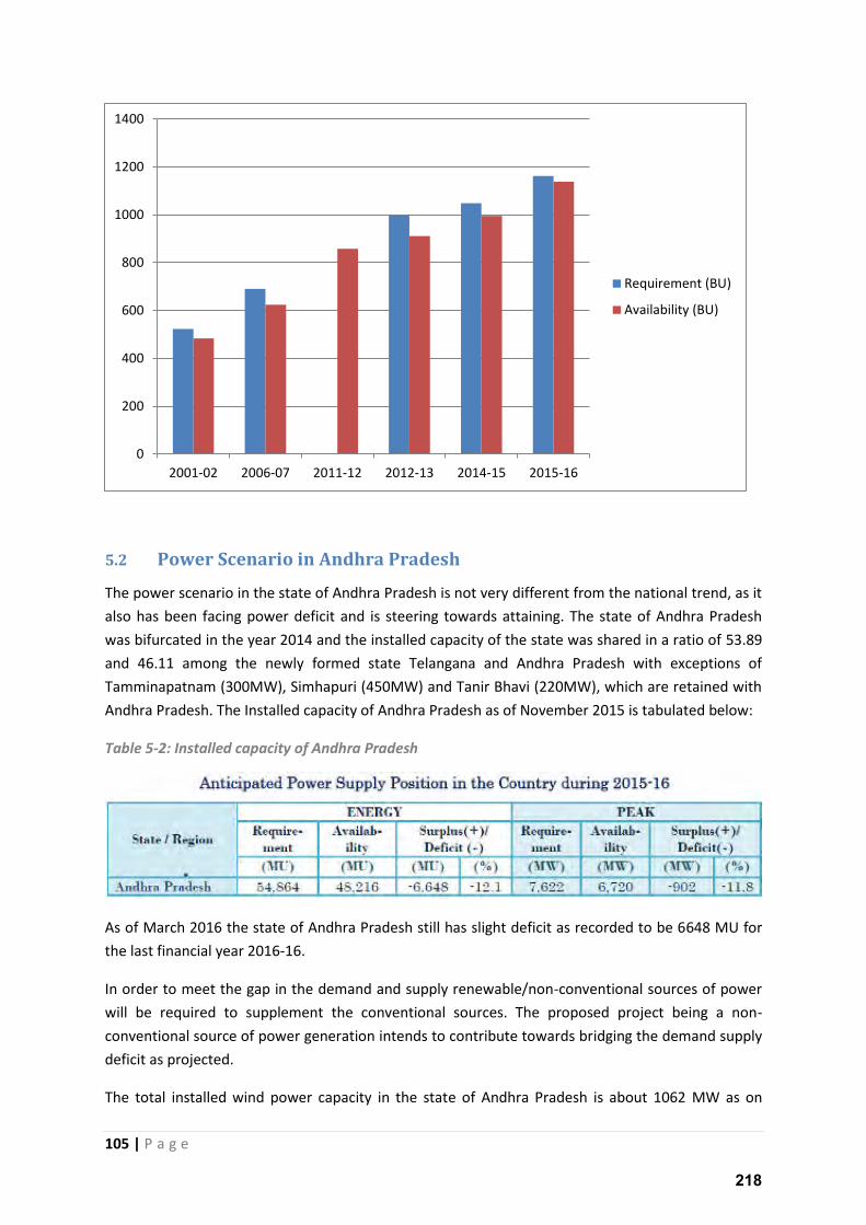
105 | P a g e
5.2 Power Scenario in Andhra Pradesh
The power scenario in the state of Andhra Pradesh is not very different from the national trend, as it
also has been facing power deficit and is steering towards attaining. The state of Andhra Pradesh
was bifurcated in the year 2014 and the installed capacity of the state was shared in a ratio of 53.89
and 46.11 among the newly formed state Telangana and Andhra Pradesh with exceptions of
Tamminapatnam (300MW), Simhapuri (450MW) and Tanir Bhavi (220MW), which are retained with
Andhra Pradesh. The Installed capacity of Andhra Pradesh as of November 2015 is tabulated below:
Table 5-2: Installed capacity of Andhra Pradesh
As of March 2016 the state of Andhra Pradesh still has slight deficit as recorded to be 6648 MU for
the last financial year 2016-16.
In order to meet the gap in the demand and supply renewable/non-conventional sources of power
will be required to supplement the conventional sources. The proposed project being a non-
conventional source of power generation intends to contribute towards bridging the demand supply
deficit as projected.
The total installed wind power capacity in the state of Andhra Pradesh is about 1062 MW as on
0
200
400
600
800
1000
1200
1400
2001-02 2006-07 2011-12 2012-13 2014-15 2015-16
Requirement (BU)
Availability (BU)
218
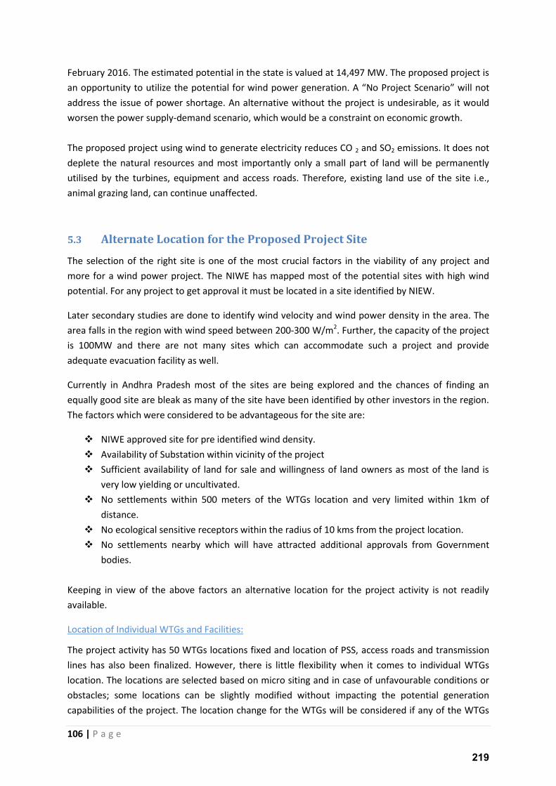
106 | P a g e
February 2016. The estimated potential in the state is valued at 14,497 MW. The proposed project is
an opportunity to utilize the potential for wind po e ge e atio . A No Project Scenario will not
address the issue of power shortage. An alternative without the project is undesirable, as it would
worsen the power supply-demand scenario, which would be a constraint on economic growth.
The proposed project using wind to generate electricity reduces CO 2 and SO2 emissions. It does not
deplete the natural resources and most importantly only a small part of land will be permanently
utilised by the turbines, equipment and access roads. Therefore, existing land use of the site i.e.,
animal grazing land, can continue unaffected.
5.3 Alternate Location for the Proposed Project Site
The selection of the right site is one of the most crucial factors in the viability of any project and
more for a wind power project. The NIWE has mapped most of the potential sites with high wind
potential. For any project to get approval it must be located in a site identified by NIEW.
Later secondary studies are done to identify wind velocity and wind power density in the area. The
area falls in the region with wind speed between 200-300 W/m2. Further, the capacity of the project
is 100MW and there are not many sites which can accommodate such a project and provide
adequate evacuation facility as well.
Currently in Andhra Pradesh most of the sites are being explored and the chances of finding an
equally good site are bleak as many of the site have been identified by other investors in the region.
The factors which were considered to be advantageous for the site are:
NIWE approved site for pre identified wind density.
Availability of Substation within vicinity of the project
Sufficient availability of land for sale and willingness of land owners as most of the land is
very low yielding or uncultivated.
No settlements within 500 meters of the WTGs location and very limited within 1km of
distance.
No ecological sensitive receptors within the radius of 10 kms from the project location.
No settlements nearby which will have attracted additional approvals from Government
bodies.
Keeping in view of the above factors an alternative location for the project activity is not readily
available.
Location of Individual WTGs and Facilities:
The project activity has 50 WTGs locations fixed and location of PSS, access roads and transmission
lines has also been finalized. However, there is little flexibility when it comes to individual WTGs
location. The locations are selected based on micro siting and in case of unfavourable conditions or
obstacles; some locations can be slightly modified without impacting the potential generation
capabilities of the project. The location change for the WTGs will be considered if any of the WTGs
219
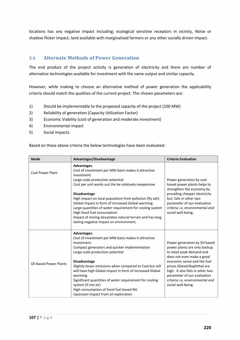
107 | P a g e
locations has any negative impact including; ecological sensitive receptors in vicinity, Noise or
shadow flicker impact, land available with marginalized farmers or any other socially driven impact.
5.4 Alternate Methods of Power Generation
The end product of the project activity is generation of electricity and there are number of
alternative technologies available for investment with the same output and similar capacity.
However, while making to choose an alternative method of power generation the applicability
criteria should match the qualities of the current project. The chosen parameters are:
1) Should be implementable to the proposed capacity of the project (100 MW)
2) Reliability of generation (Capacity Utilization Factor)
3) Economic Viability (cost of generation and moderate investment)
4) Environmental impact
5) Social impacts.
Based on these above criteria the below technologies have been evaluated:
Mode Advantages/Disadvantage Criteria Evaluation
Coal Power Plant
Advantages:
Cost of investment per MW basis makes it attractive
investment
Large scale production potential
Cost per unit works out the be relatively inexpensive
Disadvantage
High impact on local population from pollution (fly ash)
Global impact in form of increased Global warming.
Large quantities of water requirement for cooling system
High fossil fuel consumption
Impact of mining devastates natural terrain and has long
lasting negative impact on environment;
Power generation by coal
based power plants helps to
strengthen the economy by
providing cheaper electricity
but, fails in other two
parameter of our evaluation
criteria i.e, environmental and
social well-being.
Oil Based Power Plants
Advantages:
Cost of investment per MW basis makes it attractive
investment.
Compact generators and quicker implementation
Large scale production potential
Disadvantage
Slightly lesser emissions when compared to Coal but still
will have high Global impact in form of increased Global
warming.
Significant quantities of water requirement for cooling
system (if not air)
High consumption of fossil fuel based NG
Upstream impact from oil exploration
Power generation by Oil based
power plants are only backup
to meet peak demand and
does not even make a good
economic sense and the fuel
prices (Diesel/Naphtha) are
high. It also fails in other two
parameter of our evaluation
criteria i.e, environmental and
social well-being.
220
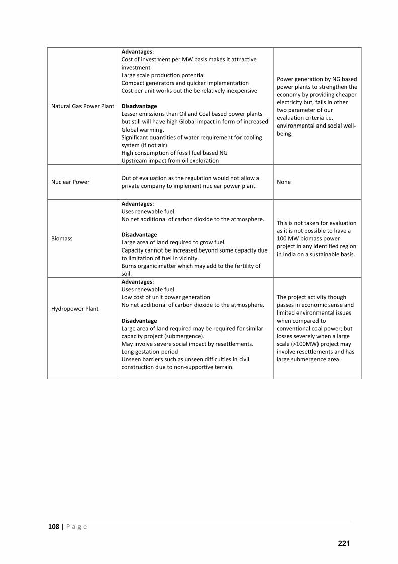
108 | P a g e
Natural Gas Power Plant
Advantages:
Cost of investment per MW basis makes it attractive
investment
Large scale production potential
Compact generators and quicker implementation
Cost per unit works out the be relatively inexpensive
Disadvantage
Lesser emissions than Oil and Coal based power plants
but still will have high Global impact in form of increased
Global warming.
Significant quantities of water requirement for cooling
system (if not air)
High consumption of fossil fuel based NG
Upstream impact from oil exploration
Power generation by NG based
power plants to strengthen the
economy by providing cheaper
electricity but, fails in other
two parameter of our
evaluation criteria i.e,
environmental and social well-
being.
Nuclear Power Out of evaluation as the regulation would not allow a
private company to implement nuclear power plant. None
Biomass
Advantages:
Uses renewable fuel
No net additional of carbon dioxide to the atmosphere.
Disadvantage
Large area of land required to grow fuel.
Capacity cannot be increased beyond some capacity due
to limitation of fuel in vicinity.
Burns organic matter which may add to the fertility of
soil.
This is not taken for evaluation
as it is not possible to have a
100 MW biomass power
project in any identified region
in India on a sustainable basis.
Hydropower Plant
Advantages:
Uses renewable fuel
Low cost of unit power generation
No net additional of carbon dioxide to the atmosphere.
Disadvantage
Large area of land required may be required for similar
capacity project (submergence).
May involve severe social impact by resettlements.
Long gestation period
Unseen barriers such as unseen difficulties in civil
construction due to non-supportive terrain.
The project activity though
passes in economic sense and
limited environmental issues
when compared to
conventional coal power; but
losses severely when a large
scale (>100MW) project may
involve resettlements and has
large submergence area.
221
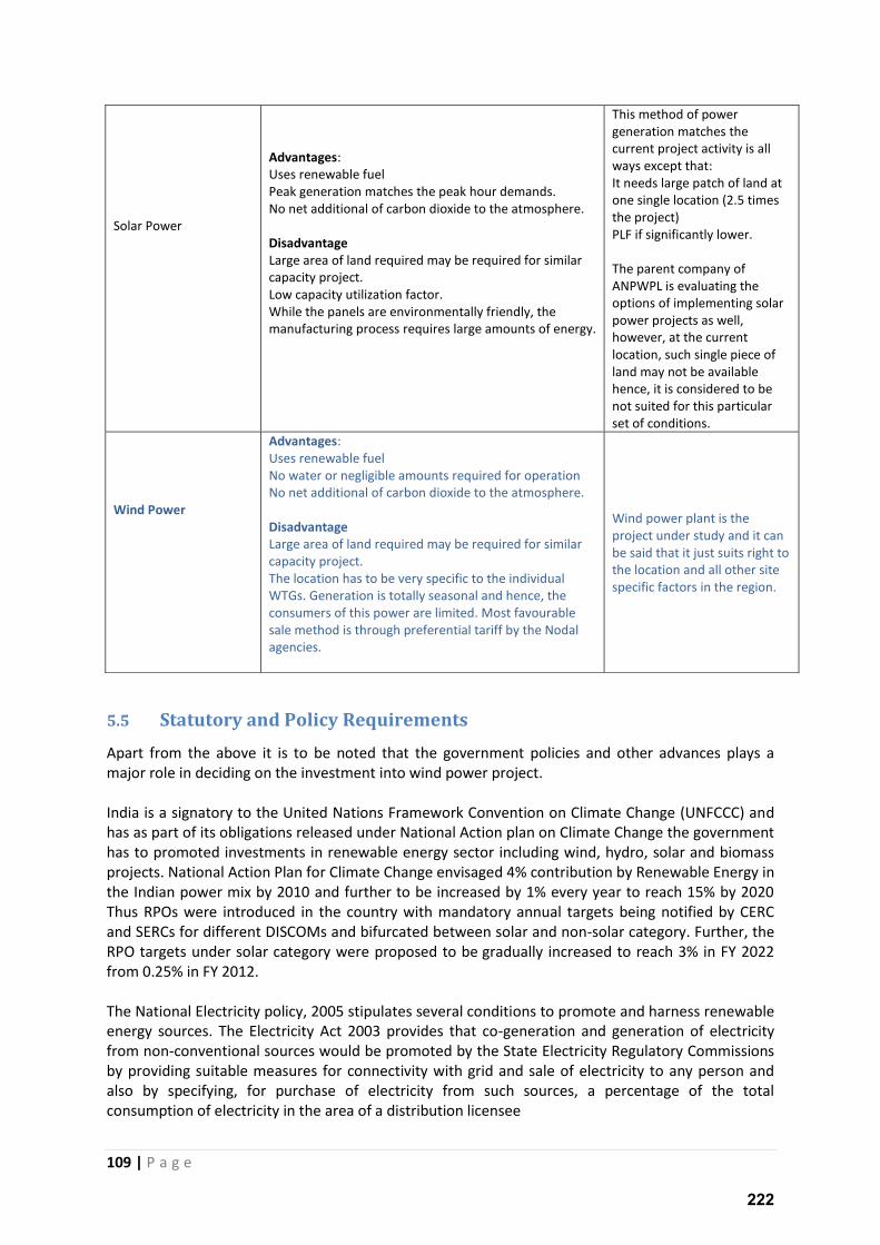
109 | P a g e
5.5 Statutory and Policy Requirements
Apart from the above it is to be noted that the government policies and other advances plays a
major role in deciding on the investment into wind power project.
India is a signatory to the United Nations Framework Convention on Climate Change (UNFCCC) and
has as part of its obligations released under National Action plan on Climate Change the government
has to promoted investments in renewable energy sector including wind, hydro, solar and biomass
projects. National Action Plan for Climate Change envisaged 4% contribution by Renewable Energy in
the Indian power mix by 2010 and further to be increased by 1% every year to reach 15% by 2020
Thus RPOs were introduced in the country with mandatory annual targets being notified by CERC
and SERCs for different DISCOMs and bifurcated between solar and non-solar category. Further, the
RPO targets under solar category were proposed to be gradually increased to reach 3% in FY 2022
from 0.25% in FY 2012.
The National Electricity policy, 2005 stipulates several conditions to promote and harness renewable
energy sources. The Electricity Act 2003 provides that co-generation and generation of electricity
from non-conventional sources would be promoted by the State Electricity Regulatory Commissions
by providing suitable measures for connectivity with grid and sale of electricity to any person and
also by specifying, for purchase of electricity from such sources, a percentage of the total
consumption of electricity in the area of a distribution licensee
Solar Power
Advantages:
Uses renewable fuel
Peak generation matches the peak hour demands.
No net additional of carbon dioxide to the atmosphere.
Disadvantage
Large area of land required may be required for similar
capacity project.
Low capacity utilization factor.
While the panels are environmentally friendly, the
manufacturing process requires large amounts of energy.
This method of power
generation matches the
current project activity is all
ways except that:
It needs large patch of land at
one single location (2.5 times
the project)
PLF if significantly lower.
The parent company of
ANPWPL is evaluating the
options of implementing solar
power projects as well,
however, at the current
location, such single piece of
land may not be available
hence, it is considered to be
not suited for this particular
set of conditions.
Wind Power
Advantages:
Uses renewable fuel
No water or negligible amounts required for operation
No net additional of carbon dioxide to the atmosphere.
Disadvantage
Large area of land required may be required for similar
capacity project.
The location has to be very specific to the individual
WTGs. Generation is totally seasonal and hence, the
consumers of this power are limited. Most favourable
sale method is through preferential tariff by the Nodal
agencies.
Wind power plant is the
project under study and it can
be said that it just suits right to
the location and all other site
specific factors in the region.
222
110 | P a g e
The following fiscal and tax incentives have been offered by the Central and State government for
promotion of wind power projects
Generation Based Incentive (GBI): MNRE had introduced GBI scheme. Under the scheme,
presently, a GBI of Rs. 0.50 per unit of electricity fed into the grid will be provided to wind
electricity producers for a period of ten years with a maximum incentive of Rs. 1 crore per
MW
Renewable Purchase Obligation: The Electricity Act, 2003 requires in section 86(1)(e), the
state commission to specify renewable purchase obligation (RPO) for the obligated entities.
Preferential Tariff: The NTP provides DISCOMs to procure power from renewable energy
sources at a preferential tariff in order to promote such projects. Preferential Tariff in case
of the project activity works out to be 4.83 Rs/kWh
Renewable Energy Certificates: The REC certificates are provided to renewable project from
generating electricity. It will enable the RE producer and distributor to engage in trading
within a specified band. However, there are a number of restrictions on the eligibility and
technical constrains in trade. The project does not fall in eligibility criteria if it opts for
preferential tariff.
Concession on import duty on specified wind turbine components;
10 year income tax holiday for wind power generation projects;
100% exemption from excise duty on certain wind turbine components;
100% FDI investment allowed in renewable energy generation projects;
Government of Andhra Pradesh has also a number of benefits declared for wind power projects
through its Wind Power Policy. These benefits which are available to wind power project being
implemented in Andhra Pradesh are listed below:
Power Evacuation: Wind power projects will be exempted from paying the supervision charges to
APTransco/Discom towards the internal evacuation infrastructure within the wind farm site and up-
to pooling sub-station.
APTransco/Discom will dispose the proposals for the technical feasibility for evacuation within 14
days from the date of receipt of application.
Transmission and Distribution charges for wheeling of power: There will be no T&D charges for
wheeling of power generated from wind power projects, to the desired location/s for captive
use/third party sale within the State through grid.
Energy Banking: Banking of 100% of energy shall be permitted during all 12 months of the year.
Banking charges shall be adjusted in kind @ 2% of the energy delivered at the point of drawal. (April
to March)
Open Access: Intra-state Open Access clearance for the whole tenure of the project or 25 years
whichever is earlier will be granted.
Electricity Duty: All wind power projects are exempted from paying Electricity Duty in case of sale of
power to APDiscom.
223
111 | P a g e
Deemed Public Private Partnership (PPP) Status: Deemed PPP status shall be provided for projects
coming up under Category I and have entered into a PPA with APDiscom for sale of power.
Non Agriculture Status: Deemed Non-Agricultural (NA) status for the land where wind power
projects will be accorded, on payment of applicable statutory fees.
Deemed Industry Status: Generation of electricity from wind power projects shall be treated as
eligible industry under the schemes administered by the Industries Department and incentives
available to industrial units under such schemes shall be available to the wind power producers.
Must run status: Injection from wind power projects shall be considered to be deemed scheduled
subject to prevailing regulations/grid code of appropriate commission.
Pollution Clearance: Wind power projects will be exempted from obtaining any NOC/Consent for
establishment under pollution control laws from AP Pollution Control Board.
5.6 Alternative Technologies within Wind:
Gamesa G97 IIIA: The p oje t a ti it is i stalli g the Ga esa s G IIIA WTGs hi h e plo o e of the most advanced technologies in their WTGs and hence are capable of giving reliable power
generation from the machines. The fact is also evident form the fact that Gamesa has made a
generation guarantee of 30% PLF/year form the project.
Credentials: The G97 IIIA by Gamesa is one of the most advanced WTG available in the market today.
Below are some of the unique features of G97 IIIA:
New optimized blades are thick roots and light body made of fibre glass and carbon fibre
using re-impregnation methods.
Increased hub height of 104 m, which is one of the tallest available in the market at the time
of finalizing supply order.
New airfoil technology reduces noise from the WTG
New Nacelle improves continuous & quicker cooling
Power curve:
Figure 5-3: Figure & Table showing Power Curve comparison of various models
224
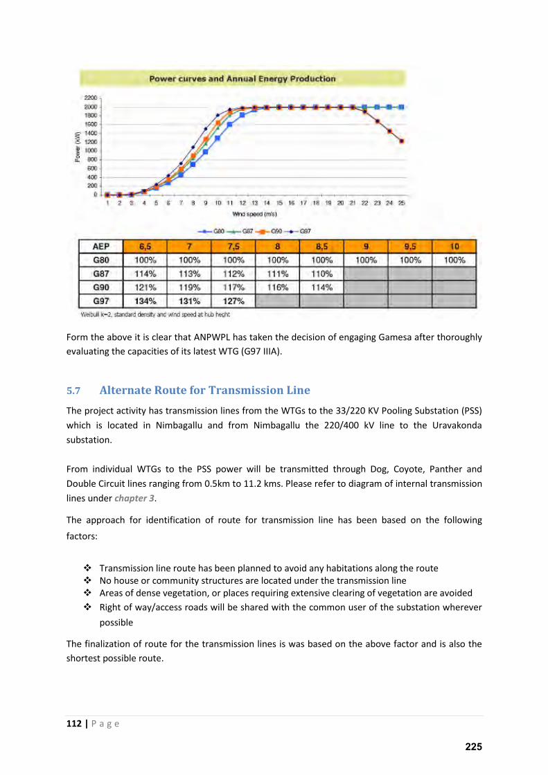
112 | P a g e
Form the above it is clear that ANPWPL has taken the decision of engaging Gamesa after thoroughly
evaluating the capacities of its latest WTG (G97 IIIA).
5.7 Alternate Route for Transmission Line
The project activity has transmission lines from the WTGs to the 33/220 KV Pooling Substation (PSS)
which is located in Nimbagallu and from Nimbagallu the 220/400 kV line to the Uravakonda
substation.
From individual WTGs to the PSS power will be transmitted through Dog, Coyote, Panther and
Double Circuit lines ranging from 0.5km to 11.2 kms. Please refer to diagram of internal transmission
lines under chapter 3. The approach for identification of route for transmission line has been based on the following
factors:
Transmission line route has been planned to avoid any habitations along the route
No house or community structures are located under the transmission line
Areas of dense vegetation, or places requiring extensive clearing of vegetation are avoided
Right of way/access roads will be shared with the common user of the substation wherever
possible The finalization of route for the transmission lines is was based on the above factor and is also the
shortest possible route.
225
113 | P a g e
5.8 Conclusion
The project site conditions and criteria for investment makes the project unique in itself and hence
does not has a convincing viable alternative. The conditions of land availability, high wind density,
less water availability, absence of eco sensitive zones make is apt for implementation of a wind
power project.
226
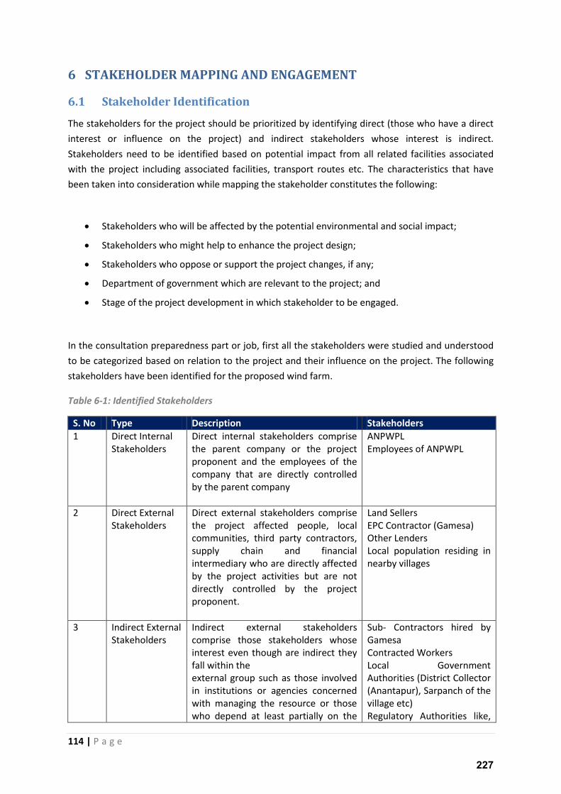
114 | P a g e
6 STAKEHOLDER MAPPING AND ENGAGEMENT
6.1 Stakeholder Identification
The stakeholders for the project should be prioritized by identifying direct (those who have a direct
interest or influence on the project) and indirect stakeholders whose interest is indirect.
Stakeholders need to be identified based on potential impact from all related facilities associated
with the project including associated facilities, transport routes etc. The characteristics that have
been taken into consideration while mapping the stakeholder constitutes the following:
Stakeholders who will be affected by the potential environmental and social impact;
Stakeholders who might help to enhance the project design;
Stakeholders who oppose or support the project changes, if any;
Department of government which are relevant to the project; and
Stage of the project development in which stakeholder to be engaged.
In the consultation preparedness part or job, first all the stakeholders were studied and understood
to be categorized based on relation to the project and their influence on the project. The following
stakeholders have been identified for the proposed wind farm.
Table 6-1: Identified Stakeholders
S. No Type Description Stakeholders
1 Direct Internal
Stakeholders
Direct internal stakeholders comprise
the parent company or the project
proponent and the employees of the
company that are directly controlled
by the parent company
ANPWPL
Employees of ANPWPL
2 Direct External
Stakeholders
Direct external stakeholders comprise
the project affected people, local
communities, third party contractors,
supply chain and financial
intermediary who are directly affected
by the project activities but are not
directly controlled by the project
proponent.
Land Sellers
EPC Contractor (Gamesa)
Other Lenders
Local population residing in
nearby villages
3 Indirect External
Stakeholders
Indirect external stakeholders
comprise those stakeholders whose
interest even though are indirect they
fall within the
external group such as those involved
in institutions or agencies concerned
with managing the resource or those
who depend at least partially on the
Sub- Contractors hired by
Gamesa
Contracted Workers
Local Government
Authorities (District Collector
(Anantapur), Sarpanch of the
village etc)
Regulatory Authorities like,
227
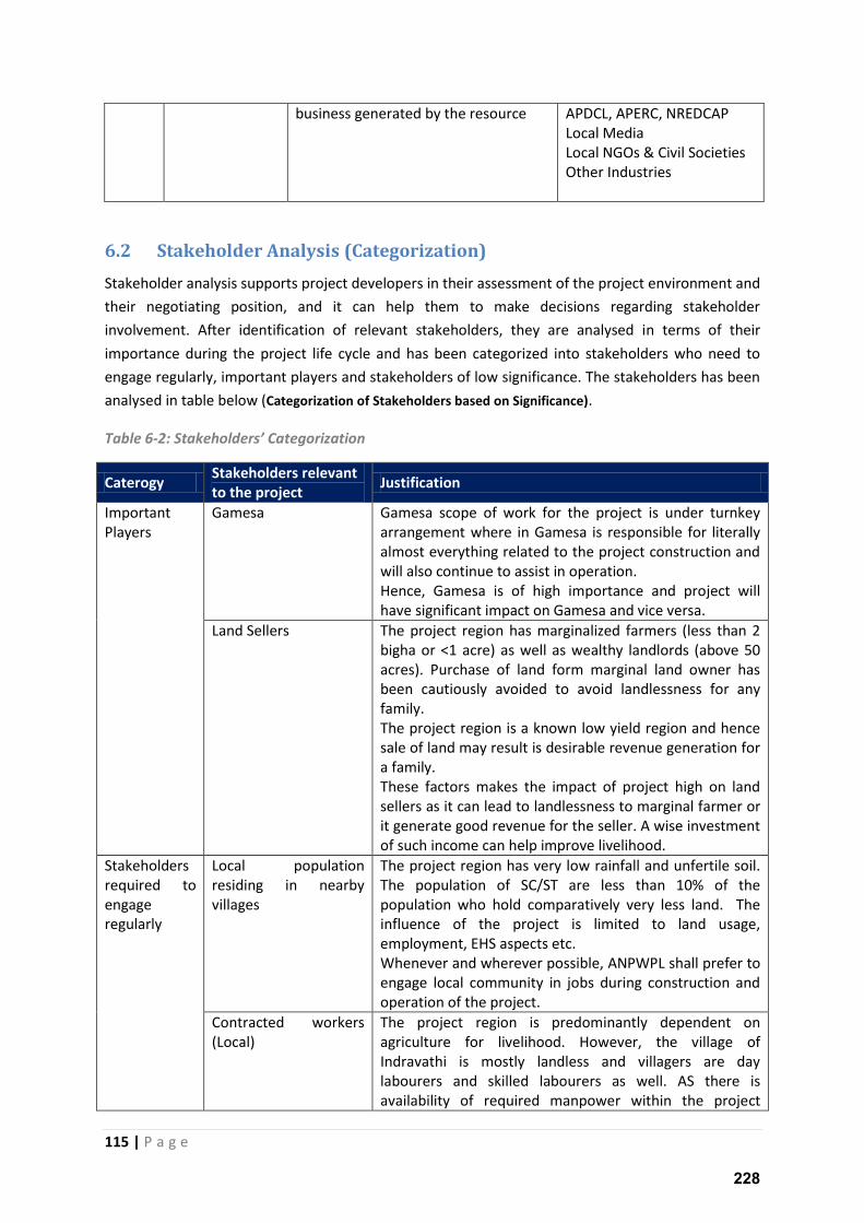
115 | P a g e
business generated by the resource APDCL, APERC, NREDCAP
Local Media
Local NGOs & Civil Societies
Other Industries
6.2 Stakeholder Analysis (Categorization)
Stakeholder analysis supports project developers in their assessment of the project environment and
their negotiating position, and it can help them to make decisions regarding stakeholder
involvement. After identification of relevant stakeholders, they are analysed in terms of their
importance during the project life cycle and has been categorized into stakeholders who need to
engage regularly, important players and stakeholders of low significance. The stakeholders has been
analysed in table below (Categorization of Stakeholders based on Significance).
Table 6-2: “takeholders’ Categorizatio
Caterogy Stakeholders relevant
to the project Justification
Important
Players
Gamesa Gamesa scope of work for the project is under turnkey
arrangement where in Gamesa is responsible for literally
almost everything related to the project construction and
will also continue to assist in operation.
Hence, Gamesa is of high importance and project will
have significant impact on Gamesa and vice versa.
Land Sellers The project region has marginalized farmers (less than 2
bigha or <1 acre) as well as wealthy landlords (above 50
acres). Purchase of land form marginal land owner has
been cautiously avoided to avoid landlessness for any
family.
The project region is a known low yield region and hence
sale of land may result is desirable revenue generation for
a family.
These factors makes the impact of project high on land
sellers as it can lead to landlessness to marginal farmer or
it generate good revenue for the seller. A wise investment
of such income can help improve livelihood.
Stakeholders
required to
engage
regularly
Local population
residing in nearby
villages
The project region has very low rainfall and unfertile soil.
The population of SC/ST are less than 10% of the
population who hold comparatively very less land. The
influence of the project is limited to land usage,
employment, EHS aspects etc.
Whenever and wherever possible, ANPWPL shall prefer to
engage local community in jobs during construction and
operation of the project.
Contracted workers
(Local)
The project region is predominantly dependent on
agriculture for livelihood. However, the village of
Indravathi is mostly landless and villagers are day
labourers and skilled labourers as well. AS there is
availability of required manpower within the project
228
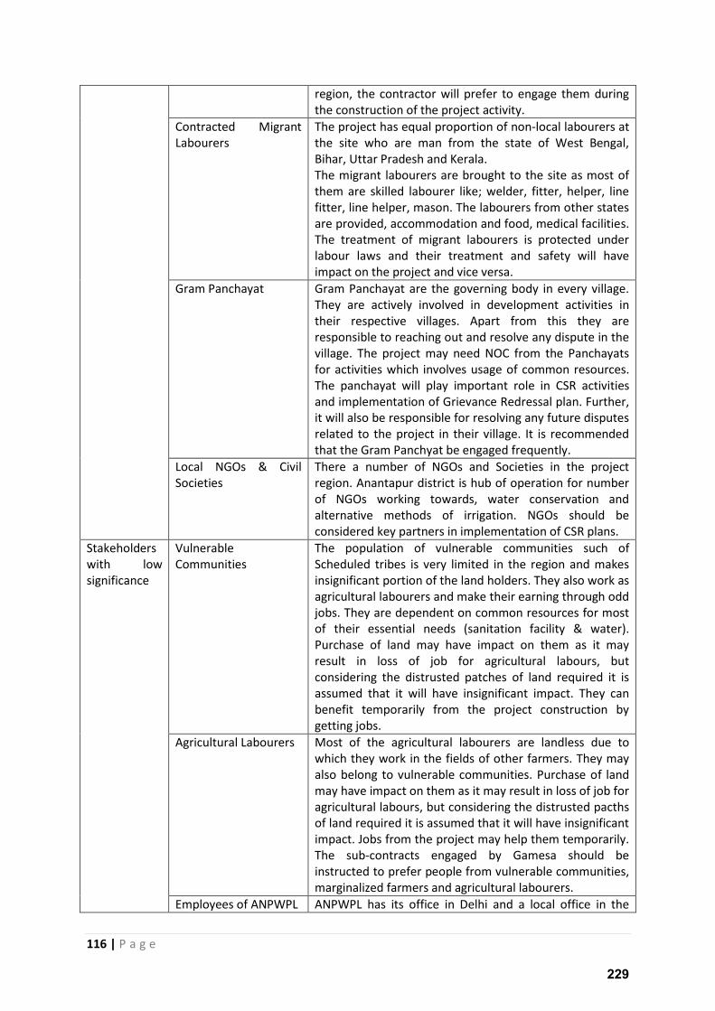
116 | P a g e
region, the contractor will prefer to engage them during
the construction of the project activity.
Contracted Migrant
Labourers
The project has equal proportion of non-local labourers at
the site who are man from the state of West Bengal,
Bihar, Uttar Pradesh and Kerala.
The migrant labourers are brought to the site as most of
them are skilled labourer like; welder, fitter, helper, line
fitter, line helper, mason. The labourers from other states
are provided, accommodation and food, medical facilities.
The treatment of migrant labourers is protected under
labour laws and their treatment and safety will have
impact on the project and vice versa.
Gram Panchayat Gram Panchayat are the governing body in every village.
They are actively involved in development activities in
their respective villages. Apart from this they are
responsible to reaching out and resolve any dispute in the
village. The project may need NOC from the Panchayats
for activities which involves usage of common resources.
The panchayat will play important role in CSR activities
and implementation of Grievance Redressal plan. Further,
it will also be responsible for resolving any future disputes
related to the project in their village. It is recommended
that the Gram Panchyat be engaged frequently.
Local NGOs & Civil
Societies
There a number of NGOs and Societies in the project
region. Anantapur district is hub of operation for number
of NGOs working towards, water conservation and
alternative methods of irrigation. NGOs should be
considered key partners in implementation of CSR plans.
Stakeholders
with low
significance
Vulnerable
Communities
The population of vulnerable communities such of
Scheduled tribes is very limited in the region and makes
insignificant portion of the land holders. They also work as
agricultural labourers and make their earning through odd
jobs. They are dependent on common resources for most
of their essential needs (sanitation facility & water).
Purchase of land may have impact on them as it may
result in loss of job for agricultural labours, but
considering the distrusted patches of land required it is
assumed that it will have insignificant impact. They can
benefit temporarily from the project construction by
getting jobs.
Agricultural Labourers Most of the agricultural labourers are landless due to
which they work in the fields of other farmers. They may
also belong to vulnerable communities. Purchase of land
may have impact on them as it may result in loss of job for
agricultural labours, but considering the distrusted pacths
of land required it is assumed that it will have insignificant
impact. Jobs from the project may help them temporarily.
The sub-contracts engaged by Gamesa should be
instructed to prefer people from vulnerable communities,
marginalized farmers and agricultural labourers.
Employees of ANPWPL ANPWPL has its office in Delhi and a local office in the
229
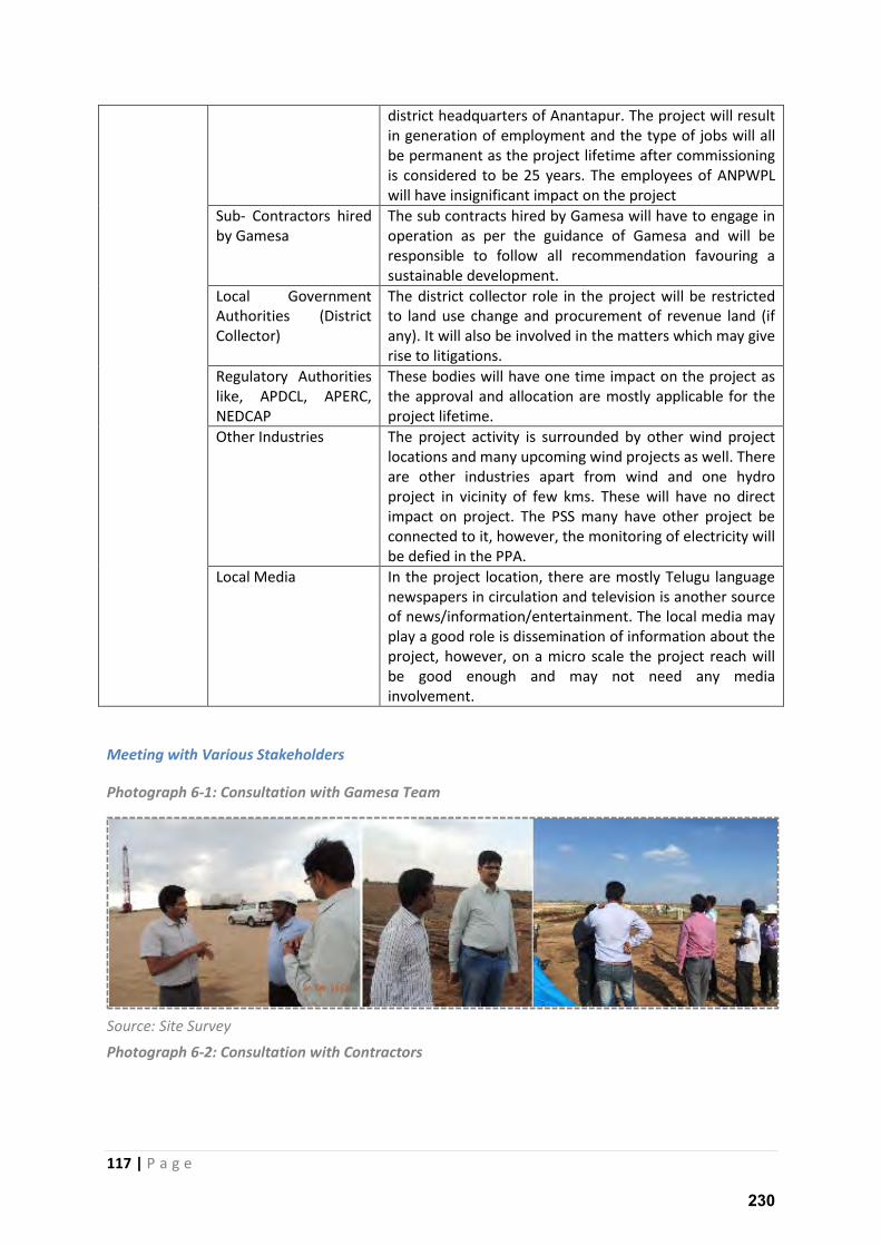
117 | P a g e
district headquarters of Anantapur. The project will result
in generation of employment and the type of jobs will all
be permanent as the project lifetime after commissioning
is considered to be 25 years. The employees of ANPWPL
will have insignificant impact on the project
Sub- Contractors hired
by Gamesa
The sub contracts hired by Gamesa will have to engage in
operation as per the guidance of Gamesa and will be
responsible to follow all recommendation favouring a
sustainable development.
Local Government
Authorities (District
Collector)
The district collector role in the project will be restricted
to land use change and procurement of revenue land (if
any). It will also be involved in the matters which may give
rise to litigations.
Regulatory Authorities
like, APDCL, APERC,
NEDCAP
These bodies will have one time impact on the project as
the approval and allocation are mostly applicable for the
project lifetime.
Other Industries The project activity is surrounded by other wind project
locations and many upcoming wind projects as well. There
are other industries apart from wind and one hydro
project in vicinity of few kms. These will have no direct
impact on project. The PSS many have other project be
connected to it, however, the monitoring of electricity will
be defied in the PPA.
Local Media In the project location, there are mostly Telugu language
newspapers in circulation and television is another source
of news/information/entertainment. The local media may
play a good role is dissemination of information about the
project, however, on a micro scale the project reach will
be good enough and may not need any media
involvement.
Meeting with Various Stakeholders
Photograph 6-1: Consultation with Gamesa Team
Source: Site Survey
Photograph 6-2: Consultation with Contractors
230
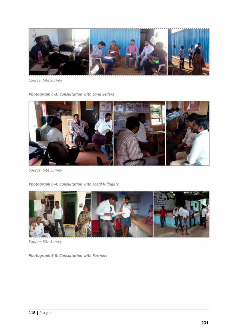
118 | P a g e
Source: Site Survey
Photograph 6-3: Consultation with Land Sellers
Source: Site Survey
Photograph 6-4: Consultation with Local Villagers
Source: Site Survey
Photograph 6-5: Consultation with Farmers
231
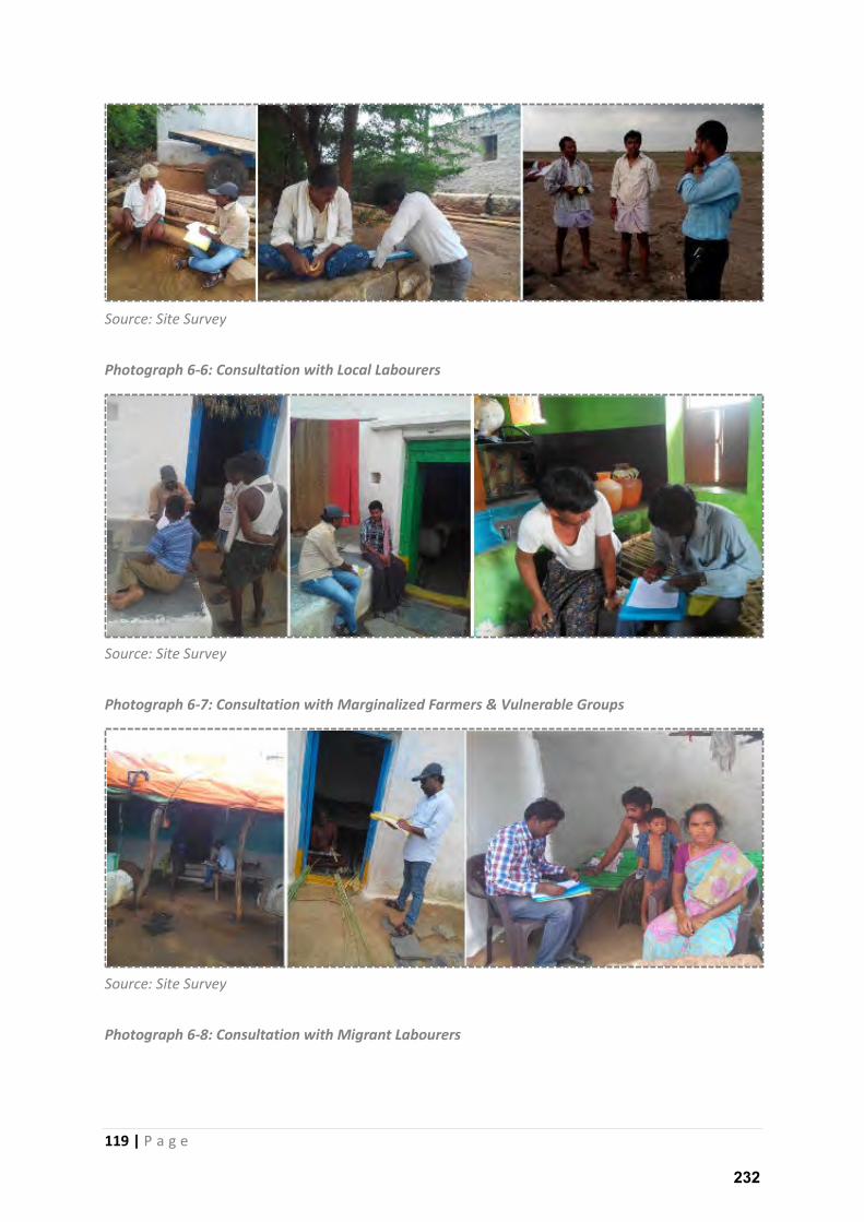
119 | P a g e
Source: Site Survey
Photograph 6-6: Consultation with Local Labourers
Source: Site Survey
Photograph 6-7: Consultation with Marginalized Farmers & Vulnerable Groups
Source: Site Survey
Photograph 6-8: Consultation with Migrant Labourers
232
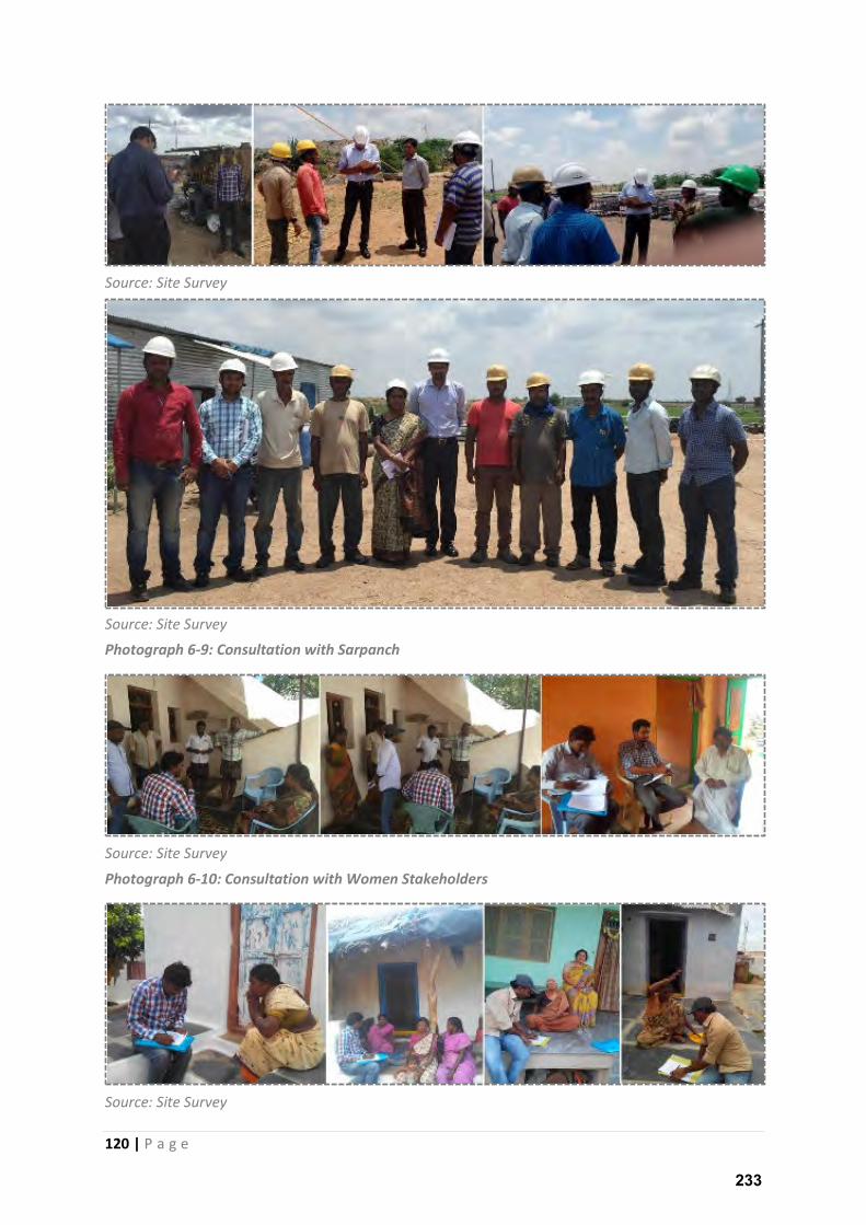
120 | P a g e
Source: Site Survey
Source: Site Survey
Photograph 6-9: Consultation with Sarpanch
Source: Site Survey
Photograph 6-10: Consultation with Women Stakeholders
Source: Site Survey
233
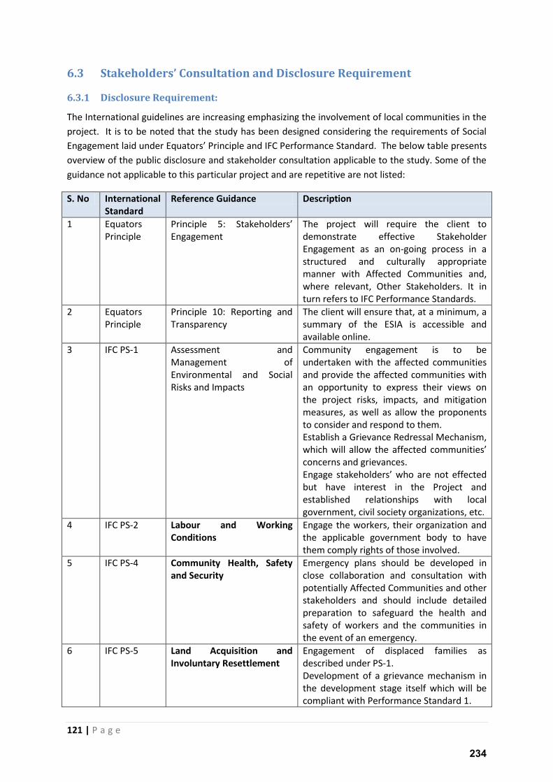
121 | P a g e
6.3 Stakeholders’ Consultation and Disclosure Requirement
6.3.1 Disclosure Requirement:
The International guidelines are increasing emphasizing the involvement of local communities in the
project. It is to be noted that the study has been designed considering the requirements of Social
E gage e t laid u de E uato s P i iple a d IFC Pe fo a e “ta da d. The elo table presents
overview of the public disclosure and stakeholder consultation applicable to the study. Some of the
guidance not applicable to this particular project and are repetitive are not listed:
S. No International
Standard
Reference Guidance Description
1 Equators
Principle
P i iple : “takeholde s Engagement
The project will require the client to
demonstrate effective Stakeholder
Engagement as an on-going process in a
structured and culturally appropriate
manner with Affected Communities and,
where relevant, Other Stakeholders. It in
turn refers to IFC Performance Standards.
2 Equators
Principle
Principle 10: Reporting and
Transparency
The client will ensure that, at a minimum, a
summary of the ESIA is accessible and
available online.
3 IFC PS-1 Assessment and
Management of
Environmental and Social
Risks and Impacts
Community engagement is to be
undertaken with the affected communities
and provide the affected communities with
an opportunity to express their views on
the project risks, impacts, and mitigation
measures, as well as allow the proponents
to consider and respond to them.
Establish a Grievance Redressal Mechanism,
hi h ill allo the affe ted o u ities concerns and grievances.
E gage stakeholde s ho a e ot effe ted but have interest in the Project and
established relationships with local
government, civil society organizations, etc.
4 IFC PS-2 Labour and Working
Conditions
Engage the workers, their organization and
the applicable government body to have
them comply rights of those involved.
5 IFC PS-4 Community Health, Safety
and Security
Emergency plans should be developed in
close collaboration and consultation with
potentially Affected Communities and other
stakeholders and should include detailed
preparation to safeguard the health and
safety of workers and the communities in
the event of an emergency.
6 IFC PS-5 Land Acquisition and
Involuntary Resettlement
Engagement of displaced families as
described under PS-1.
Development of a grievance mechanism in
the development stage itself which will be
compliant with Performance Standard 1.
234
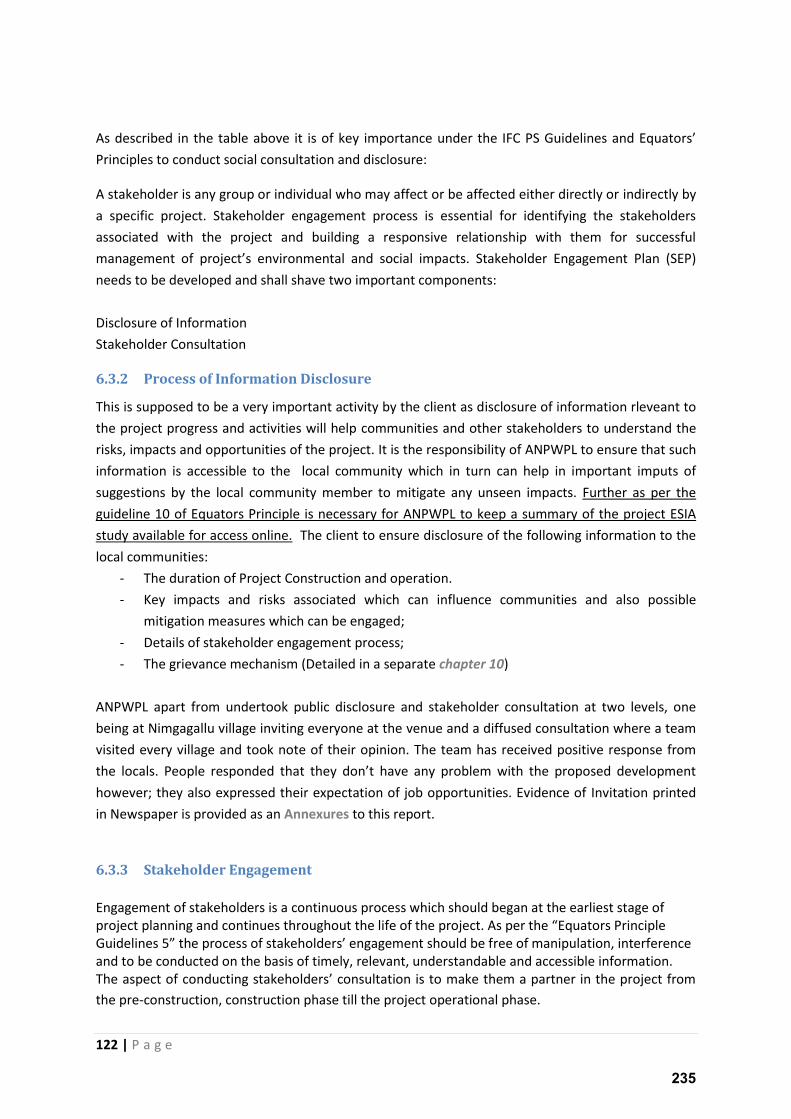
122 | P a g e
As des i ed i the ta le a o e it is of ke i po ta e u de the IFC P“ Guideli es a d E uato s Principles to conduct social consultation and disclosure:
A stakeholder is any group or individual who may affect or be affected either directly or indirectly by
a specific project. Stakeholder engagement process is essential for identifying the stakeholders
associated with the project and building a responsive relationship with them for successful
a age e t of p oje t s e i o e tal a d so ial i pacts. Stakeholder Engagement Plan (SEP)
needs to be developed and shall shave two important components:
Disclosure of Information
Stakeholder Consultation
6.3.2 Process of Information Disclosure
This is supposed to be a very important activity by the client as disclosure of information rleveant to
the project progress and activities will help communities and other stakeholders to understand the
risks, impacts and opportunities of the project. It is the responsibility of ANPWPL to ensure that such
information is accessible to the local community which in turn can help in important imputs of
suggestions by the local community member to mitigate any unseen impacts. Further as per the
guideline 10 of Equators Principle is necessary for ANPWPL to keep a summary of the project ESIA
study available for access online. The client to ensure disclosure of the following information to the
local communities:
- The duration of Project Construction and operation.
- Key impacts and risks associated which can influence communities and also possible
mitigation measures which can be engaged;
- Details of stakeholder engagement process;
- The grievance mechanism (Detailed in a separate chapter 10)
ANPWPL apart from undertook public disclosure and stakeholder consultation at two levels, one
being at Nimgagallu village inviting everyone at the venue and a diffused consultation where a team
visited every village and took note of their opinion. The team has received positive response from
the locals. People responded that the do t ha e a p o le ith the p oposed de elop e t however; they also expressed their expectation of job opportunities. Evidence of Invitation printed
in Newspaper is provided as an Annexures to this report.
6.3.3 Stakeholder Engagement
Engagement of stakeholders is a continuous process which should began at the earliest stage of
p oje t pla i g a d o ti ues th oughout the life of the p oje t. As pe the E uato s P i iple Guideli es the p o ess of stakeholde s e gage e t should e free of manipulation, interference
and to be conducted on the basis of timely, relevant, understandable and accessible information.
The aspe t of o du ti g stakeholde s o sultatio is to ake the a pa t e i the p oje t f o the pre-construction, construction phase till the project operational phase.
235
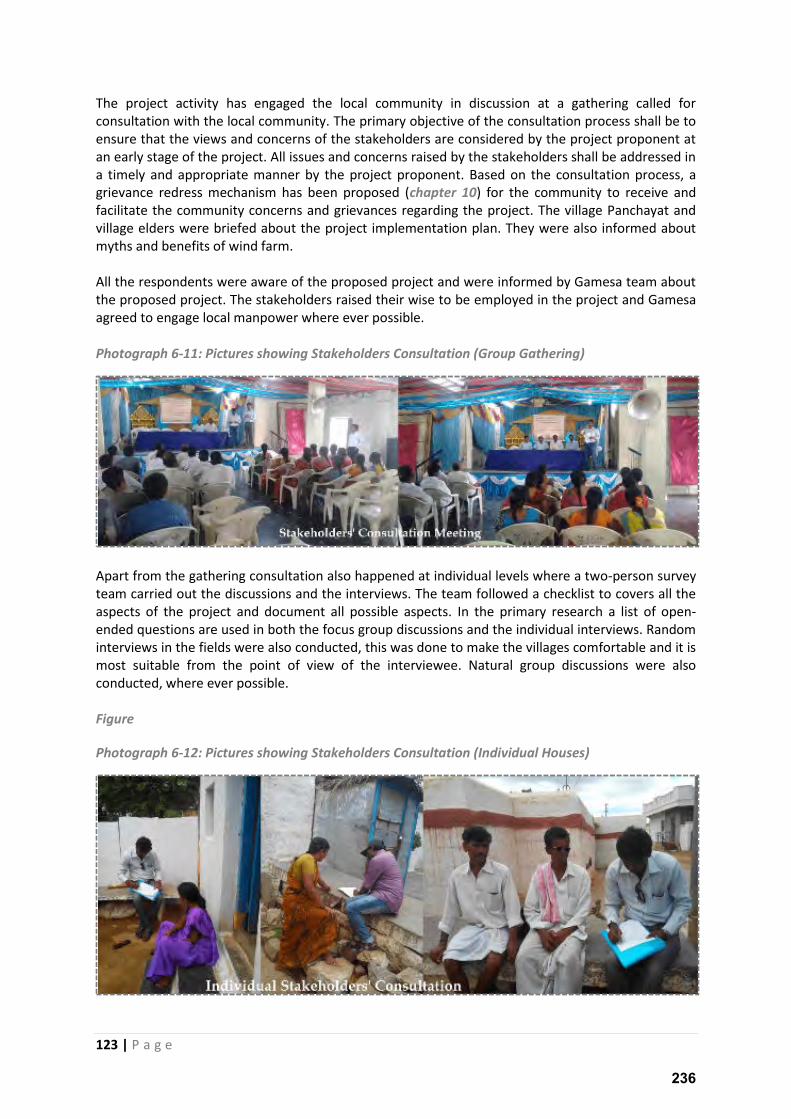
123 | P a g e
The project activity has engaged the local community in discussion at a gathering called for
consultation with the local community. The primary objective of the consultation process shall be to
ensure that the views and concerns of the stakeholders are considered by the project proponent at
an early stage of the project. All issues and concerns raised by the stakeholders shall be addressed in
a timely and appropriate manner by the project proponent. Based on the consultation process, a
grievance redress mechanism has been proposed (chapter 10) for the community to receive and
facilitate the community concerns and grievances regarding the project. The village Panchayat and
village elders were briefed about the project implementation plan. They were also informed about
myths and benefits of wind farm.
All the respondents were aware of the proposed project and were informed by Gamesa team about
the proposed project. The stakeholders raised their wise to be employed in the project and Gamesa
agreed to engage local manpower where ever possible.
Photograph 6-11: Pictures showing Stakeholders Consultation (Group Gathering)
Apart from the gathering consultation also happened at individual levels where a two-person survey
team carried out the discussions and the interviews. The team followed a checklist to covers all the
aspects of the project and document all possible aspects. In the primary research a list of open-
ended questions are used in both the focus group discussions and the individual interviews. Random
interviews in the fields were also conducted, this was done to make the villages comfortable and it is
most suitable from the point of view of the interviewee. Natural group discussions were also
conducted, where ever possible.
Figure
Photograph 6-12: Pictures showing Stakeholders Consultation (Individual Houses)
236

124 | P a g e
During the complete consultation process the team has noted the key concerns of the stakeholder
which are documented in the below table. ANPWPL in its capacity shall make required efforts to
prevent any activity which of concern to the stakeholders. Some of the concerns/recommendations
can be incorporated in the CSR plan as well.
237
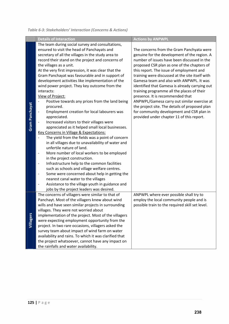
125 | P a g e
Table 6-3: “takeholders’ I tera tio Co er s & A tio s
Details of Interaction Actions by ANPWPL
Gra
m P
an
cha
ya
t
The team during social survey and consultations,
ensured to visit the head of Panchayats and
secretary of all the villages in the study area to
record their stand on the project and concerns of
the villages as a unit.
At the very first impression, it was clear that the
Gram Panchayat was favourable and in support of
development activities like implementation of the
wind power project. They key outcome from the
interacts:
View of Project:
- Positive towards any prices from the land being
procured.
- Employment creation for local labourers was
appreciated.
- Increased visitors to their villages were
appreciated as it helped small local businesses.
Key Concerns in Village & Expectations:
- The yield from the fields was a point of concern
in all villages due to unavailability of water and
unfertile nature of land.
- More number of local workers to be employed
in the project construction.
- Infrastructure help to the common facilities
such as schools and village welfare centres.
- Some were concerned about help in getting the
nearest canal water to the villages
- Assistance to the village youth in guidance and
jobs by the project leaders was desired.
The concerns from the Gram Panchyata were
genuine for the development of the region. A
number of issues have been discussed in the
proposed CSR plan as one of the chapters of
this report. The issue of employment and
training were discussed at the site itself with
Gamesa team and also with ANPWPL. It was
identified that Gamesa is already carrying out
training programme all the places of their
presence. It is recommended that
ANPWPL/Gamesa carry out similar exercise at
the project site. The details of proposed plan
for community development and CSR plan in
provided under chapter 11 of this report.
Vil
lag
ers
The concerns of villagers were similar to that of
Panchayt. Most of the villagers knew about wind
wills and have seen similar projects in surrounding
villages. They were not worried about
implementation of the project. Most of the villagers
were expecting employment opportunity from the
project. In two rare occasions, villagers asked the
survey team about impact of wind farm on water
availability and rains. To which it was clarified that
the project whatsoever, cannot have any impact on
the rainfalls and water availability.
ANPWPL where ever possible shall try to
employ the local community people and is
possible train to the required skill set level.
238
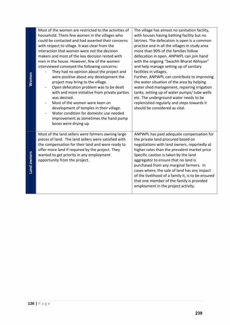
126 | P a g e
Wo
me
n
Most of the women are restricted to the activities of
household. There few women in the villages who
could be contacted and had asserted their concerns
with respect to village. It was clear from the
interaction that women were not the decision
makers and most of the key decision rested with
men in the house. However, few of the women
interviewed conveyed the following concerns:
- They had no opinion about the project and
were positive about any development the
project may bring to the village.
- Open defecation problem was to be dealt
with and more initiative from private parties
was desired.
- Most of the women were keen on
development of temples in their village.
- Water condition for domestic use needed
improvement as sometimes the hand pump
bores were drying up.
The village has almost no sanitation facility,
with houses having bathing facility but no
latrines. The defecation is open is a common
practice and in all the villages in study area
more than 90% of the families follow
defecation in open. ANPWPL can join hand
ith the o goi g “ a hh Bha at A hi a and help manage setting up of sanitary
facilities in villages.
Further, ANPWPL can contribute to improving
the water situation of the area by helping
water shed management, repairing irrigation
tanks, setting up of water pumps/ tube wells
etc. The underground water needs to be
replenished regularly and steps towards it
should be considered as vital.
Lan
d o
wn
ers
Most of the land sellers were farmers owning large
pieces of land. The land sellers were satisfied with
the compensation for their land and were ready to
offer more land if required by the project. They
wanted to get priority in any employment
opportunity from the project.
ANPWPL has paid adequate compensation for
the private land procured based on
negotiations with land owners, reportedly at
higher rates than the prevalent market price
Specific caution is taken by the land
aggregator to ensure that no land is
purchased from any marginal farmers. In
cases where, the sale of land has any impact
of the livelihood of a family it, is to be ensured
that one member of the family is provided
employment in the project activity.
239
127 | P a g e
7 DESCRIPTION OF ENVIRONEMENT
7.1 Introduction
Collection of base line data is an integral aspect of the preparation of environmental impact
assessment report. Baseline data reflects the present status of environment before the initiation of
any activity of the proposed project. The possible effects due to the proposed project are estimated
and superimposed on the compiled baseline data subsequently to assess environmental impacts.
Baseline environment assessment was conducted in the impact zone of 5 kms surrounding the site
area during the months of August – November, 2015. Studies were undertaken to generate baseline
data of micrometeorology, air quality, water quality, noise levels, flora and fauna, land use, soil
quality, and socio-economic status of the community were collected in a circular area of 5 kms
adius su ou di g the p oje t s oute ost site lo atio s.
Kosher Climate undertook a reconnaissance survey of the proposed site and surroundings in order to
understand the environmental and social setting of the proposed wind farm project. The
reconnaissance survey was followed by primary baseline data generation for environment and social
aspects of the study area. The photo-documentation of the study is presented in the Annexures.
7.2 Physical Environment
7.2.1 Topography:
Topographically, major parts of the district is covered by Karnataka Plateau, with gently sloping
topography and elevation ranging between 425 m and 600 m above mean sea level.
The highest elevation of the area is observed on south most corner of the area near village
Amidayala with an elevation of 487 m above mean sea level, which represent undulated terrain
formation. The lowest elevation is 462 m above mean sea level marked south-east of
Renumakullapalli village;
The regional topography/elevation of the area is given in below Figure.
240
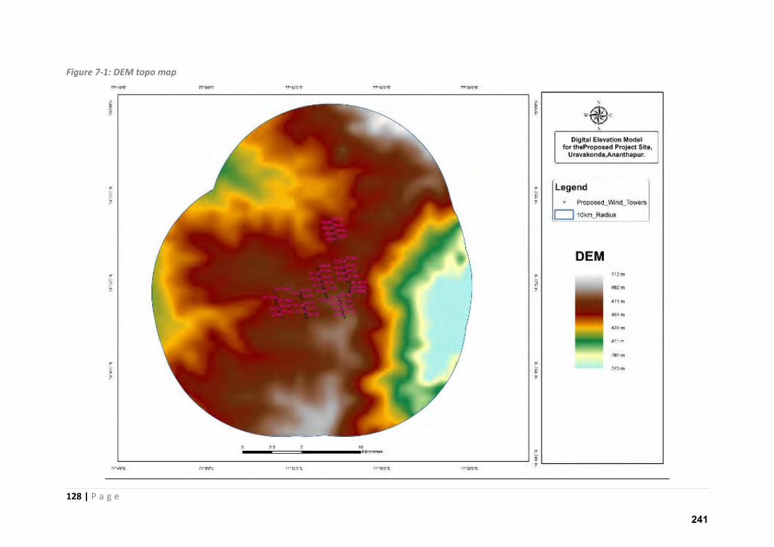
128 | P a g e
Figure 7-1: DEM topo map
241
129 | P a g e
7.2.2 LAND USE:
7.2.2.1 Introduction
The ever-growing population and limited availability of land necessitates proper utilization of
available land through scientific land use planning. Data on land use/land cover patterns, their
spatial distribution and changes are the prerequisites for making development plans. Visual
interpretation techniques through, stratification approach, with limited ground truth are used for
mapping broad categories of land use types with aerial extent and location. Information with
respect to vegetation, their types, classes, density, quality and distribution is of prime need for
adopting conservation measures, eco-balance and planning-cum-management.
Land use/land cover classification is a time consuming and expensive process. Remote sensing offers
a quick and efficient approach to the classification and mapping of land use/land cover changes over
space and time. Information on changes in land use classes their aerial extent and pattern form a
basis for future planning. Keeping this in view, Land use / Land cover assessment on 1: 50,000 scale
in 10 km radius around Project site near Uravakonda village of Ananthpur district has been taken up.
7.2.2.2 Base Map of 10km & 5km radius around proposed site
The map depicts major roads, minor roads, major and minor settlements, river/stream, Canals,
tanks, mining area existing wind towers etc. The data collected include information from Survey of
India toposheets, collateral data and updation carried out using high resolution satellite data with
limited field checks.
242
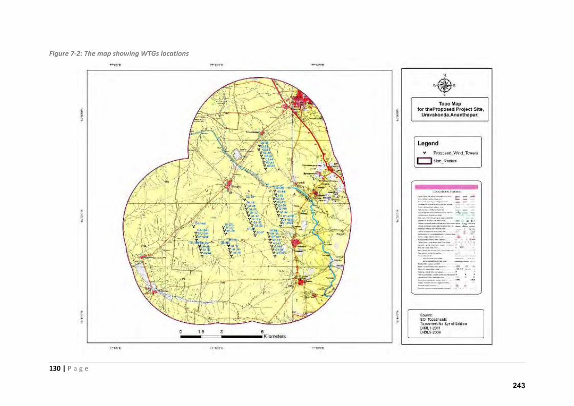
130 | P a g e
Figure 7-2: The map showing WTGs locations
243
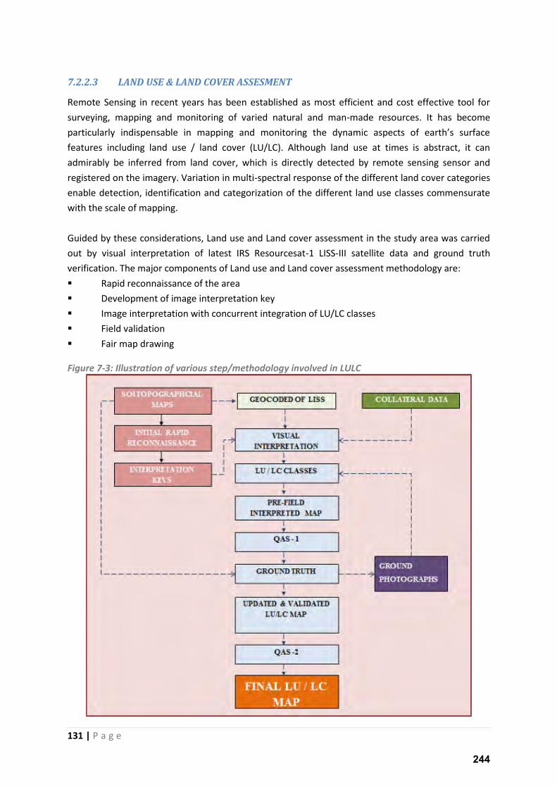
131 | P a g e
7.2.2.3 LAND USE & LAND COVER ASSESMENT
Remote Sensing in recent years has been established as most efficient and cost effective tool for
surveying, mapping and monitoring of varied natural and man-made resources. It has become
pa ti ula l i dispe sa le i appi g a d o ito i g the d a i aspe ts of ea th s su fa e features including land use / land cover (LU/LC). Although land use at times is abstract, it can
admirably be inferred from land cover, which is directly detected by remote sensing sensor and
registered on the imagery. Variation in multi-spectral response of the different land cover categories
enable detection, identification and categorization of the different land use classes commensurate
with the scale of mapping.
Guided by these considerations, Land use and Land cover assessment in the study area was carried
out by visual interpretation of latest IRS Resourcesat-1 LISS-III satellite data and ground truth
verification. The major components of Land use and Land cover assessment methodology are:
Rapid reconnaissance of the area
Development of image interpretation key
Image interpretation with concurrent integration of LU/LC classes
Field validation
Fair map drawing
Figure 7-3: Illustration of various step/methodology involved in LULC
244
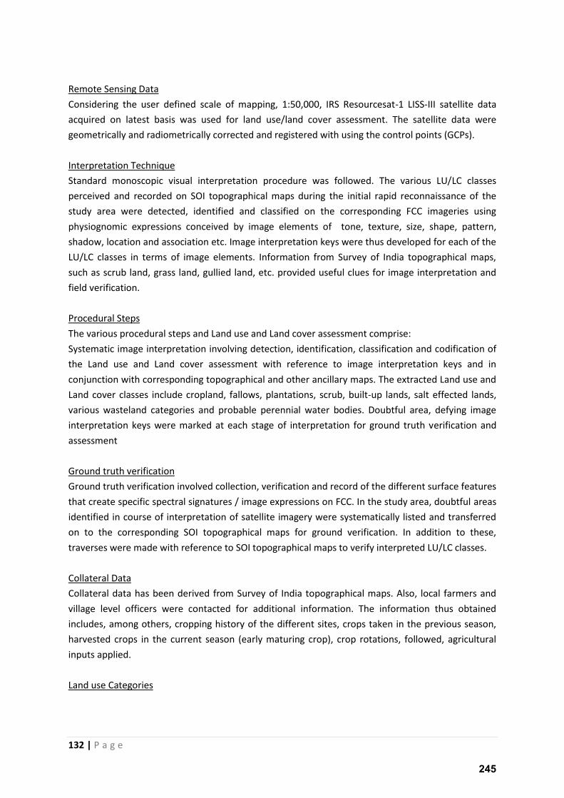
132 | P a g e
Remote Sensing Data
Considering the user defined scale of mapping, 1:50,000, IRS Resourcesat-1 LISS-III satellite data
acquired on latest basis was used for land use/land cover assessment. The satellite data were
geometrically and radiometrically corrected and registered with using the control points (GCPs).
Interpretation Technique
Standard monoscopic visual interpretation procedure was followed. The various LU/LC classes
perceived and recorded on SOI topographical maps during the initial rapid reconnaissance of the
study area were detected, identified and classified on the corresponding FCC imageries using
physiognomic expressions conceived by image elements of tone, texture, size, shape, pattern,
shadow, location and association etc. Image interpretation keys were thus developed for each of the
LU/LC classes in terms of image elements. Information from Survey of India topographical maps,
such as scrub land, grass land, gullied land, etc. provided useful clues for image interpretation and
field verification.
Procedural Steps
The various procedural steps and Land use and Land cover assessment comprise:
Systematic image interpretation involving detection, identification, classification and codification of
the Land use and Land cover assessment with reference to image interpretation keys and in
conjunction with corresponding topographical and other ancillary maps. The extracted Land use and
Land cover classes include cropland, fallows, plantations, scrub, built-up lands, salt effected lands,
various wasteland categories and probable perennial water bodies. Doubtful area, defying image
interpretation keys were marked at each stage of interpretation for ground truth verification and
assessment
Ground truth verification
Ground truth verification involved collection, verification and record of the different surface features
that create specific spectral signatures / image expressions on FCC. In the study area, doubtful areas
identified in course of interpretation of satellite imagery were systematically listed and transferred
on to the corresponding SOI topographical maps for ground verification. In addition to these,
traverses were made with reference to SOI topographical maps to verify interpreted LU/LC classes.
Collateral Data
Collateral data has been derived from Survey of India topographical maps. Also, local farmers and
village level officers were contacted for additional information. The information thus obtained
includes, among others, cropping history of the different sites, crops taken in the previous season,
harvested crops in the current season (early maturing crop), crop rotations, followed, agricultural
inputs applied.
Land use Categories
245

133 | P a g e
The Land use / Land cover information provides extent and spatial distribution of various Land use
and Land cover categories. The present study is conducted using satellite data and assessed visually
into six major groups.
The distributions of the different LU/LC classes together with their mapped areas are presented in
below:
246
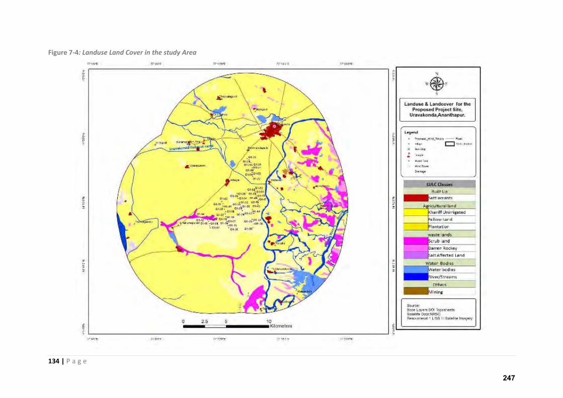
134 | P a g e
Figure 7-4: Landuse Land Cover in the study Area
247
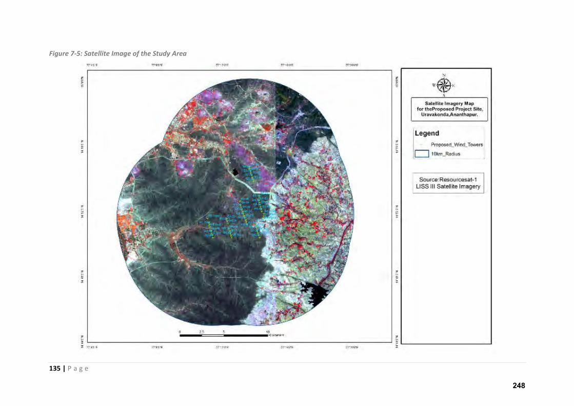
135 | P a g e
Figure 7-5: Satellite Image of the Study Area
248
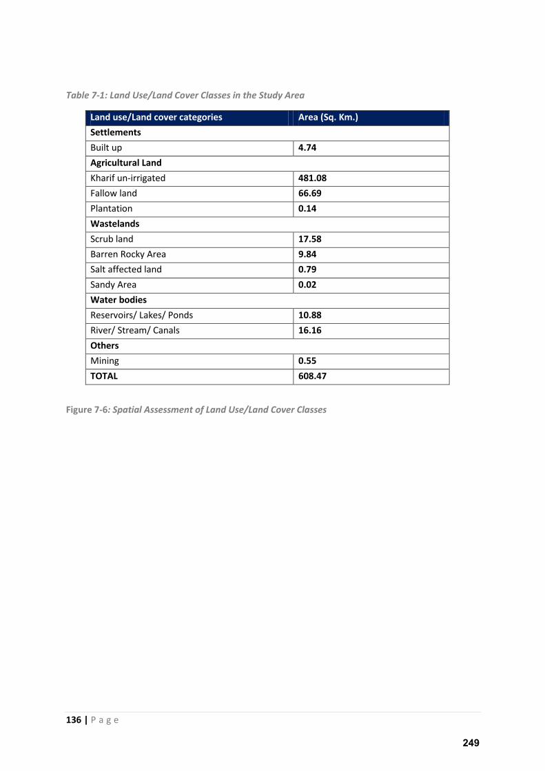
136 | P a g e
Table 7-1: Land Use/Land Cover Classes in the Study Area
Land use/Land cover categories Area (Sq. Km.)
Settlements
Built up 4.74
Agricultural Land
Kharif un-irrigated 481.08
Fallow land 66.69
Plantation 0.14
Wastelands
Scrub land 17.58
Barren Rocky Area 9.84
Salt affected land 0.79
Sandy Area 0.02
Water bodies
Reservoirs/ Lakes/ Ponds 10.88
River/ Stream/ Canals 16.16
Others
Mining 0.55
TOTAL 608.47
Figure 7-6: Spatial Assessment of Land Use/Land Cover Classes
249
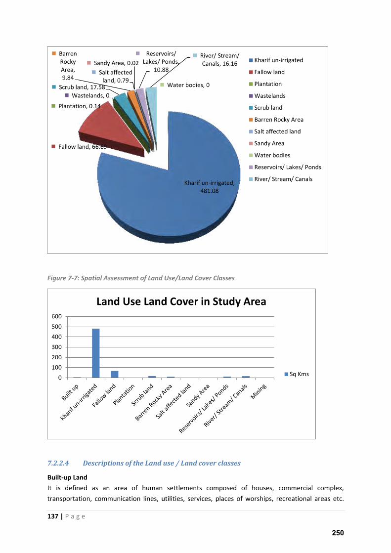
137 | P a g e
Figure 7-7: Spatial Assessment of Land Use/Land Cover Classes
7.2.2.4 Descriptions of the Land use / Land cover classes
Built-up Land
It is defined as an area of human settlements composed of houses, commercial complex,
transportation, communication lines, utilities, services, places of worships, recreational areas etc.
Kharif un-irrigated,
481.08
Fallow land, 66.69
Plantation, 0.14
Wastelands, 0
Scrub land, 17.58
Barren
Rocky
Area,
9.84 Salt affected
land, 0.79
Sandy Area, 0.02
Water bodies, 0
Reservoirs/
Lakes/ Ponds,
10.88
River/ Stream/
Canals, 16.16 Kharif un-irrigated
Fallow land
Plantation
Wastelands
Scrub land
Barren Rocky Area
Salt affected land
Sandy Area
Water bodies
Reservoirs/ Lakes/ Ponds
River/ Stream/ Canals
0
100
200
300
400
500
600
Land Use Land Cover in Study Area
Sq Kms
250
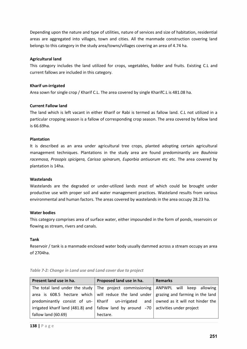
138 | P a g e
Depending upon the nature and type of utilities, nature of services and size of habitation, residential
areas are aggregated into villages, town and cities. All the manmade construction covering land
belongs to this category in the study area/towns/villages covering an area of 4.74 ha.
Agricultural land
This category includes the land utilized for crops, vegetables, fodder and fruits. Existing C.L and
current fallows are included in this category.
Kharif un-irrigated
Area sown for single crop / Kharif C.L. The area covered by single KharifC.L is 481.08 ha.
Current Fallow land
The land which is left vacant in either Kharif or Rabi is termed as fallow land. C.L not utilized in a
particular cropping season is a fallow of corresponding crop season. The area covered by fallow land
is 66.69ha.
Plantation
It is described as an area under agricultural tree crops, planted adopting certain agricultural
management techniques. Plantations in the study area are found predominantly are Bauhinia
racemosa, Prosopis spicigera, Carissa spinarum, Euporbia antiuorum etc etc. The area covered by
plantation is 14ha.
Wastelands
Wastelands are the degraded or under-utilized lands most of which could be brought under
productive use with proper soil and water management practices. Wasteland results from various
environmental and human factors. The areas covered by wastelands in the area occupy 28.23 ha.
Water bodies
This category comprises area of surface water, either impounded in the form of ponds, reservoirs or
flowing as stream, rivers and canals.
Tank
Reservoir / tank is a manmade enclosed water body usually dammed across a stream occupy an area
of 2704ha.
Table 7-2: Change in Land use and Land cover due to project
Present land use in ha. Proposed land use in ha. Remarks
The total land under the study
area is 608.5 hectare which
predominantly consist of un-
irrigated kharif land (481.8) and
fallow land (60.69)
The project commissioning
will reduce the land under
Kharif un-irrigated and
fallow land a ou d hectare.
ANPWPL will keep allowing
grazing and farming in the land
owned as it will not hinder the
activities under project
251
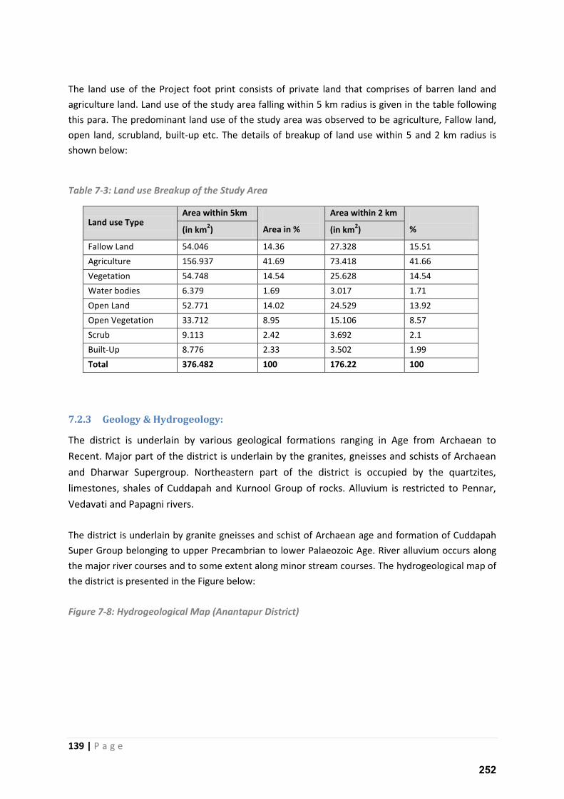
139 | P a g e
The land use of the Project foot print consists of private land that comprises of barren land and
agriculture land. Land use of the study area falling within 5 km radius is given in the table following
this para. The predominant land use of the study area was observed to be agriculture, Fallow land,
open land, scrubland, built-up etc. The details of breakup of land use within 5 and 2 km radius is
shown below:
Table 7-3: Land use Breakup of the Study Area
Land use Type Area within 5km
Area in %
Area within 2 km
% (in km2) (in km
2)
Fallow Land 54.046 14.36 27.328 15.51
Agriculture 156.937 41.69 73.418 41.66
Vegetation 54.748 14.54 25.628 14.54
Water bodies 6.379 1.69 3.017 1.71
Open Land 52.771 14.02 24.529 13.92
Open Vegetation 33.712 8.95 15.106 8.57
Scrub 9.113 2.42 3.692 2.1
Built-Up 8.776 2.33 3.502 1.99
Total 376.482 100 176.22 100
7.2.3 Geology & Hydrogeology:
The district is underlain by various geological formations ranging in Age from Archaean to
Recent. Major part of the district is underlain by the granites, gneisses and schists of Archaean
and Dharwar Supergroup. Northeastern part of the district is occupied by the quartzites,
limestones, shales of Cuddapah and Kurnool Group of rocks. Alluvium is restricted to Pennar,
Vedavati and Papagni rivers.
The district is underlain by granite gneisses and schist of Archaean age and formation of Cuddapah
Super Group belonging to upper Precambrian to lower Palaeozoic Age. River alluvium occurs along
the major river courses and to some extent along minor stream courses. The hydrogeological map of
the district is presented in the Figure below:
Figure 7-8: Hydrogeological Map (Anantapur District)
252
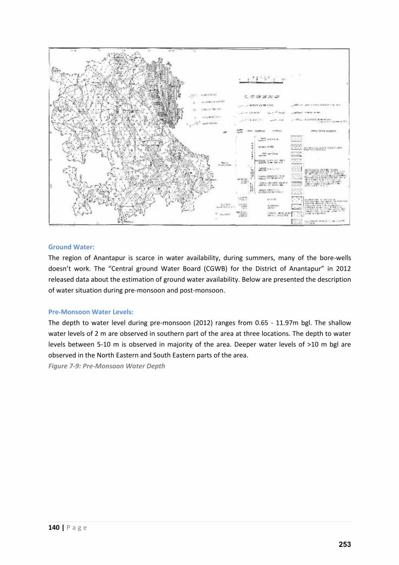
140 | P a g e
Ground Water:
The region of Anantapur is scarce in water availability, during summers, many of the bore-wells
does t o k. The Ce t al g ou d Wate Boa d CGWB fo the Dist i t of A a tapu i released data about the estimation of ground water availability. Below are presented the description
of water situation during pre-monsoon and post-monsoon.
Pre-Monsoon Water Levels:
The depth to water level during pre-monsoon (2012) ranges from 0.65 - 11.97m bgl. The shallow
water levels of 2 m are observed in southern part of the area at three locations. The depth to water
levels between 5-10 m is observed in majority of the area. Deeper water levels of >10 m bgl are
observed in the North Eastern and South Eastern parts of the area.
Figure 7-9: Pre-Monsoon Water Depth
253
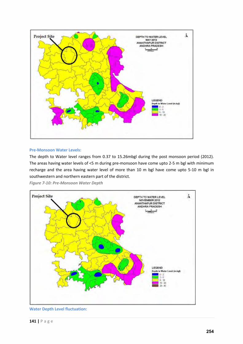
141 | P a g e
Pre-Monsoon Water Levels:
The depth to Water level ranges from 0.37 to 15.26mbgl during the post monsoon period (2012).
The areas having water levels of <5 m during pre-monsoon have come upto 2-5 m bgl with minimum
recharge and the area having water level of more than 10 m bgl have come upto 5-10 m bgl in
southwestern and northern eastern part of the district.
Figure 7-10: Pre-Monsoon Water Depth
Water Depth Level fluctuation:
254
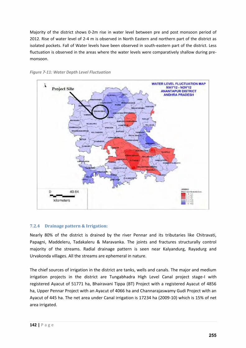
142 | P a g e
Majority of the district shows 0-2m rise in water level between pre and post monsoon period of
2012. Rise of water level of 2-4 m is observed in North Eastern and northern part of the district as
isolated pockets. Fall of Water levels have been observed in south-eastern part of the district. Less
fluctuation is observed in the areas where the water levels were comparatively shallow during pre-
monsoon.
Figure 7-11: Water Depth Level Fluctuation
7.2.4 Drainage pattern & Irrigation:
Nearly 80% of the district is drained by the river Pennar and its tributaries like Chitravati,
Papagni, Maddeleru, Tadakaleru & Maravanka. The joints and fractures structurally control
majority of the streams. Radial drainage pattern is seen near Kalyandurg, Rayadurg and
Urvakonda villages. All the streams are ephemeral in nature.
The chief sources of irrigation in the district are tanks, wells and canals. The major and medium
irrigation projects in the district are Tungabhadra High Level Canal project stage-I with
registered Ayacut of 51771 ha, Bhairavani Tippa (BT) Project with a registered Ayacut of 4856
ha, Upper Pennar Project with an Ayacut of 4066 ha and Channarajaswamy Gudi Project with an
Ayacut of 445 ha. The net area under Canal irrigation is 17234 ha (2009-10) which is 15% of net
area irrigated.
255
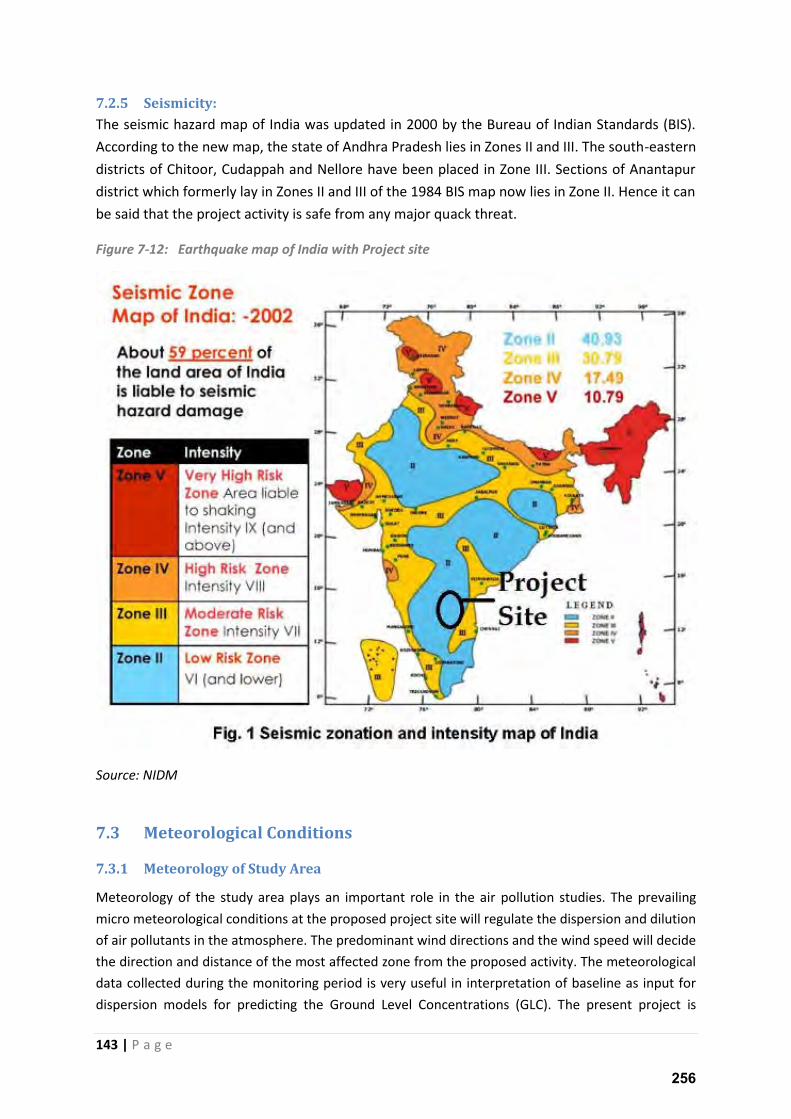
143 | P a g e
7.2.5 Seismicity:
The seismic hazard map of India was updated in 2000 by the Bureau of Indian Standards (BIS).
According to the new map, the state of Andhra Pradesh lies in Zones II and III. The south-eastern
districts of Chitoor, Cudappah and Nellore have been placed in Zone III. Sections of Anantapur
district which formerly lay in Zones II and III of the 1984 BIS map now lies in Zone II. Hence it can
be said that the project activity is safe from any major quack threat.
Figure 7-12: Earthquake map of India with Project site
Source: NIDM
7.3 Meteorological Conditions
7.3.1 Meteorology of Study Area
Meteorology of the study area plays an important role in the air pollution studies. The prevailing
micro meteorological conditions at the proposed project site will regulate the dispersion and dilution
of air pollutants in the atmosphere. The predominant wind directions and the wind speed will decide
the direction and distance of the most affected zone from the proposed activity. The meteorological
data collected during the monitoring period is very useful in interpretation of baseline as input for
dispersion models for predicting the Ground Level Concentrations (GLC). The present project is
256
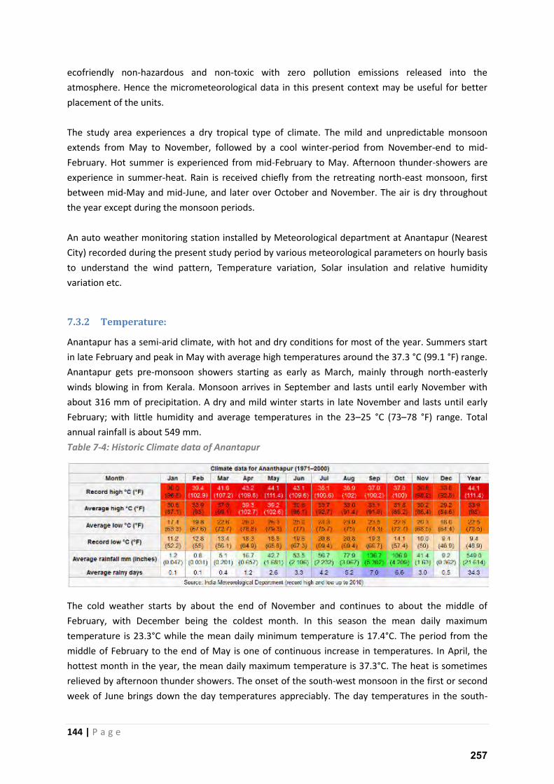
144 | P a g e
ecofriendly non-hazardous and non-toxic with zero pollution emissions released into the
atmosphere. Hence the micrometeorological data in this present context may be useful for better
placement of the units.
The study area experiences a dry tropical type of climate. The mild and unpredictable monsoon
extends from May to November, followed by a cool winter-period from November-end to mid-
February. Hot summer is experienced from mid-February to May. Afternoon thunder-showers are
experience in summer-heat. Rain is received chiefly from the retreating north-east monsoon, first
between mid-May and mid-June, and later over October and November. The air is dry throughout
the year except during the monsoon periods.
An auto weather monitoring station installed by Meteorological department at Anantapur (Nearest
City) recorded during the present study period by various meteorological parameters on hourly basis
to understand the wind pattern, Temperature variation, Solar insulation and relative humidity
variation etc.
7.3.2 Temperature:
Anantapur has a semi-arid climate, with hot and dry conditions for most of the year. Summers start
in late February and peak in May with average high temperatures around the 37.3 °C (99.1 °F) range.
Anantapur gets pre-monsoon showers starting as early as March, mainly through north-easterly
winds blowing in from Kerala. Monsoon arrives in September and lasts until early November with
about 316 mm of precipitation. A dry and mild winter starts in late November and lasts until early
February; with little humidity and average temperatures in the 23–25 °C (73–78 °F) range. Total
annual rainfall is about 549 mm.
Table 7-4: Historic Climate data of Anantapur
The cold weather starts by about the end of November and continues to about the middle of
February, with December being the coldest month. In this season the mean daily maximum
temperature is 23.3°C while the mean daily minimum temperature is 17.4°C. The period from the
middle of February to the end of May is one of continuous increase in temperatures. In April, the
hottest month in the year, the mean daily maximum temperature is 37.3°C. The heat is sometimes
relieved by afternoon thunder showers. The onset of the south-west monsoon in the first or second
week of June brings down the day temperatures appreciably. The day temperatures in the south-
257
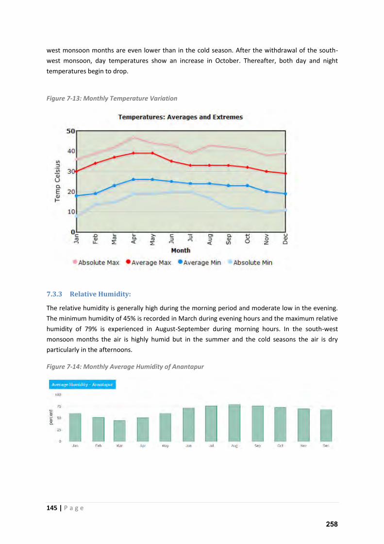
145 | P a g e
west monsoon months are even lower than in the cold season. After the withdrawal of the south-
west monsoon, day temperatures show an increase in October. Thereafter, both day and night
temperatures begin to drop.
Figure 7-13: Monthly Temperature Variation
7.3.3 Relative Humidity:
The relative humidity is generally high during the morning period and moderate low in the evening.
The minimum humidity of 45% is recorded in March during evening hours and the maximum relative
humidity of 79% is experienced in August-September during morning hours. In the south-west
monsoon months the air is highly humid but in the summer and the cold seasons the air is dry
particularly in the afternoons.
Figure 7-14: Monthly Average Humidity of Anantapur
258
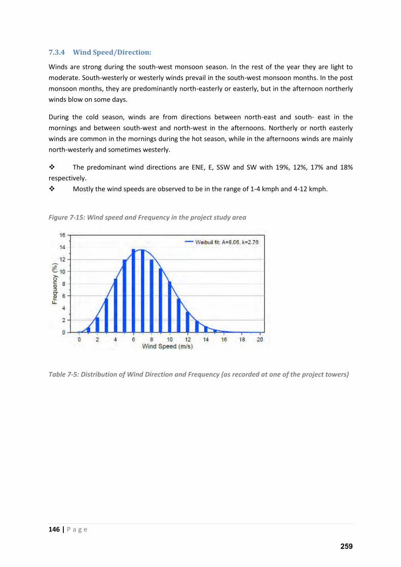
146 | P a g e
7.3.4 Wind Speed/Direction:
Winds are strong during the south-west monsoon season. In the rest of the year they are light to
moderate. South-westerly or westerly winds prevail in the south-west monsoon months. In the post
monsoon months, they are predominantly north-easterly or easterly, but in the afternoon northerly
winds blow on some days.
During the cold season, winds are from directions between north-east and south- east in the
mornings and between south-west and north-west in the afternoons. Northerly or north easterly
winds are common in the mornings during the hot season, while in the afternoons winds are mainly
north-westerly and sometimes westerly.
The predominant wind directions are ENE, E, SSW and SW with 19%, 12%, 17% and 18%
respectively.
Mostly the wind speeds are observed to be in the range of 1-4 kmph and 4-12 kmph.
Figure 7-15: Wind speed and Frequency in the project study area
Table 7-5: Distribution of Wind Direction and Frequency (as recorded at one of the project towers)
259
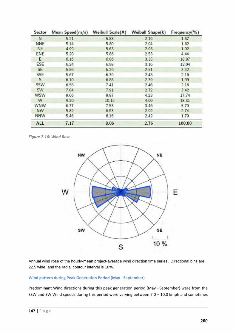
147 | P a g e
Figure 7-16: Wind Rose
Annual wind rose of the hourly-mean project-average wind direction time series. Directional bins are
22.5 wide, and the radial contour interval is 10%.
Wind pattern during Peak Generation Period (May - September)
Predominant Wind directions during this peak generation period (May –September) were from the
SSW and SW Wind speeds during this period were varying between 7.0 – 10.0 kmph and sometimes
260
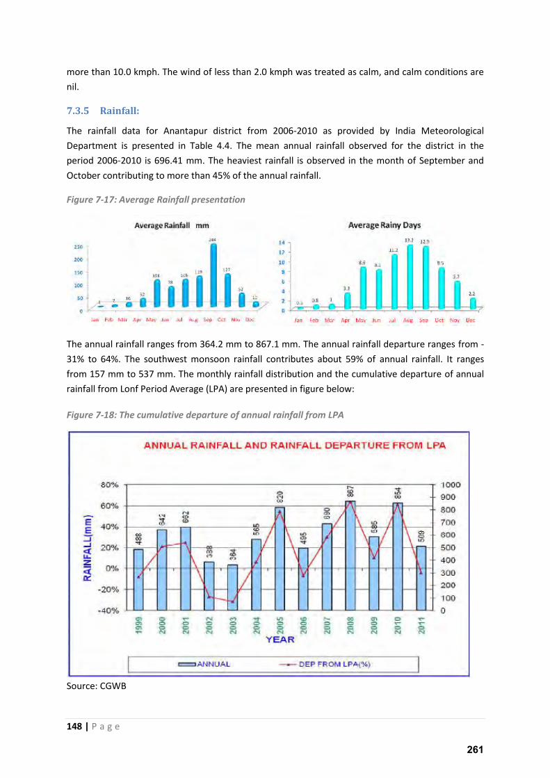
148 | P a g e
more than 10.0 kmph. The wind of less than 2.0 kmph was treated as calm, and calm conditions are
nil.
7.3.5 Rainfall:
The rainfall data for Anantapur district from 2006-2010 as provided by India Meteorological
Department is presented in Table 4.4. The mean annual rainfall observed for the district in the
period 2006-2010 is 696.41 mm. The heaviest rainfall is observed in the month of September and
October contributing to more than 45% of the annual rainfall.
Figure 7-17: Average Rainfall presentation
The annual rainfall ranges from 364.2 mm to 867.1 mm. The annual rainfall departure ranges from -
31% to 64%. The southwest monsoon rainfall contributes about 59% of annual rainfall. It ranges
from 157 mm to 537 mm. The monthly rainfall distribution and the cumulative departure of annual
rainfall from Lonf Period Average (LPA) are presented in figure below:
Figure 7-18: The cumulative departure of annual rainfall from LPA
Source: CGWB
261
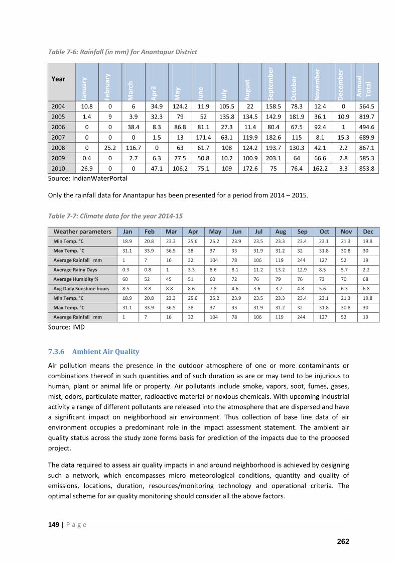
149 | P a g e
Table 7-6: Rainfall (in mm) for Anantapur District
Year Ja
nu
ary
Fe
bru
ary
Ma
rch
Ap
ril
Ma
y
Jun
e
July
Au
gu
st
Se
pte
mb
er
Oct
ob
er
No
ve
mb
er
De
cem
be
r
An
nu
al
To
tal
2004 10.8 0 6 34.9 124.2 11.9 105.5 22 158.5 78.3 12.4 0 564.5
2005 1.4 9 3.9 32.3 79 52 135.8 134.5 142.9 181.9 36.1 10.9 819.7
2006 0 0 38.4 8.3 86.8 81.1 27.3 11.4 80.4 67.5 92.4 1 494.6
2007 0 0 0 1.5 13 171.4 63.1 119.9 182.6 115 8.1 15.3 689.9
2008 0 25.2 116.7 0 63 61.7 108 124.2 193.7 130.3 42.1 2.2 867.1
2009 0.4 0 2.7 6.3 77.5 50.8 10.2 100.9 203.1 64 66.6 2.8 585.3
2010 26.9 0 0 47.1 106.2 75.1 109 172.6 75 76.4 162.2 3.3 853.8
Source: IndianWaterPortal
Only the rainfall data for Anantapur has been presented for a period from 2014 – 2015.
Table 7-7: Climate data for the year 2014-15
Weather parameters Jan Feb Mar Apr May Jun Jul Aug Sep Oct Nov Dec
Min Temp. °C 18.9 20.8 23.3 25.6 25.2 23.9 23.5 23.3 23.4 23.1 21.3 19.8
Max Temp. °C 31.1 33.9 36.5 38 37 33 31.9 31.2 32 31.8 30.8 30
Average Rainfall mm 1 7 16 32 104 78 106 119 244 127 52 19
Average Rainy Days 0.3 0.8 1 3.3 8.6 8.1 11.2 13.2 12.9 8.5 5.7 2.2
Average Humidity % 60 52 45 51 60 72 76 79 76 73 70 68
Avg Daily Sunshine hours 8.5 8.8 8.8 8.6 7.8 4.6 3.6 3.7 4.8 5.6 6.3 6.8
Min Temp. °C 18.9 20.8 23.3 25.6 25.2 23.9 23.5 23.3 23.4 23.1 21.3 19.8
Max Temp. °C 31.1 33.9 36.5 38 37 33 31.9 31.2 32 31.8 30.8 30
Average Rainfall mm 1 7 16 32 104 78 106 119 244 127 52 19
Source: IMD
7.3.6 Ambient Air Quality
Air pollution means the presence in the outdoor atmosphere of one or more contaminants or
combinations thereof in such quantities and of such duration as are or may tend to be injurious to
human, plant or animal life or property. Air pollutants include smoke, vapors, soot, fumes, gases,
mist, odors, particulate matter, radioactive material or noxious chemicals. With upcoming industrial
activity a range of different pollutants are released into the atmosphere that are dispersed and have
a significant impact on neighborhood air environment. Thus collection of base line data of air
environment occupies a predominant role in the impact assessment statement. The ambient air
quality status across the study zone forms basis for prediction of the impacts due to the proposed
project.
The data required to assess air quality impacts in and around neighborhood is achieved by designing
such a network, which encompasses micro meteorological conditions, quantity and quality of
emissions, locations, duration, resources/monitoring technology and operational criteria. The
optimal scheme for air quality monitoring should consider all the above factors.
262
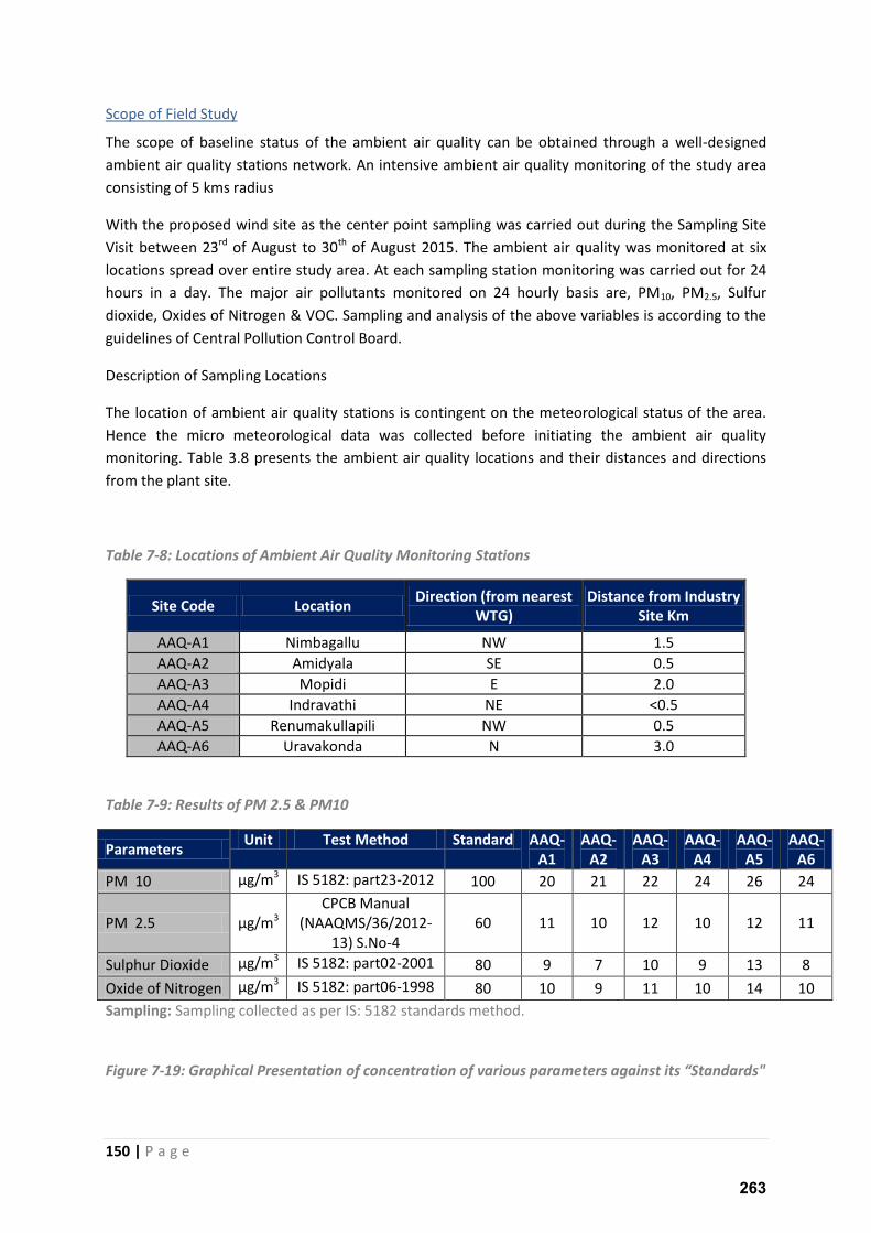
150 | P a g e
Scope of Field Study
The scope of baseline status of the ambient air quality can be obtained through a well-designed
ambient air quality stations network. An intensive ambient air quality monitoring of the study area
consisting of 5 kms radius
With the proposed wind site as the center point sampling was carried out during the Sampling Site
Visit between 23rd of August to 30th of August 2015. The ambient air quality was monitored at six
locations spread over entire study area. At each sampling station monitoring was carried out for 24
hours in a day. The major air pollutants monitored on 24 hourly basis are, PM10, PM2.5, Sulfur
dioxide, Oxides of Nitrogen & VOC. Sampling and analysis of the above variables is according to the
guidelines of Central Pollution Control Board.
Description of Sampling Locations
The location of ambient air quality stations is contingent on the meteorological status of the area.
Hence the micro meteorological data was collected before initiating the ambient air quality
monitoring. Table 3.8 presents the ambient air quality locations and their distances and directions
from the plant site.
Table 7-8: Locations of Ambient Air Quality Monitoring Stations
Site Code Location Direction (from nearest
WTG)
Distance from Industry
Site Km
AAQ-A1 Nimbagallu NW 1.5
AAQ-A2 Amidyala SE 0.5
AAQ-A3 Mopidi E 2.0
AAQ-A4 Indravathi NE <0.5
AAQ-A5 Renumakullapili NW 0.5
AAQ-A6 Uravakonda N 3.0
Table 7-9: Results of PM 2.5 & PM10
Parameters Unit Test Method Standard AAQ-
A1
AAQ-
A2
AAQ-
A3
AAQ-
A4
AAQ-
A5
AAQ-
A6
PM 10 µg/m3 IS 5182: part23-2012 100 20 21 22 24 26 24
PM 2.5 µg/m3
CPCB Manual
(NAAQMS/36/2012-
13) S.No-4
60 11 10 12 10 12 11
Sulphur Dioxide µg/m3 IS 5182: part02-2001 80 9 7 10 9 13 8
Oxide of Nitrogen µg/m3 IS 5182: part06-1998 80 10 9 11 10 14 10
Sampling: Sampling collected as per IS: 5182 standards method.
Figure 7-19: Graphical Prese tatio of o e tratio of arious para eters agai st its “ta dards"
263
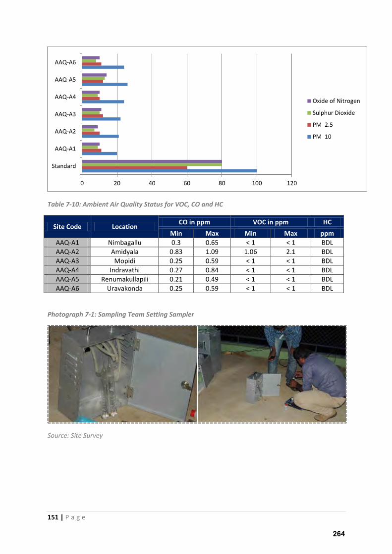
151 | P a g e
Table 7-10: Ambient Air Quality Status for VOC, CO and HC
Site Code Location CO in ppm VOC in ppm HC
Min Max Min Max ppm
AAQ-A1 Nimbagallu 0.3 0.65 < 1 < 1 BDL
AAQ-A2 Amidyala 0.83 1.09 1.06 2.1 BDL
AAQ-A3 Mopidi 0.25 0.59 < 1 < 1 BDL
AAQ-A4 Indravathi 0.27 0.84 < 1 < 1 BDL
AAQ-A5 Renumakullapili 0.21 0.49 < 1 < 1 BDL
AAQ-A6 Uravakonda 0.25 0.59 < 1 < 1 BDL
Photograph 7-1: Sampling Team Setting Sampler
Source: Site Survey
0 20 40 60 80 100 120
Standard
AAQ-A1
AAQ-A2
AAQ-A3
AAQ-A4
AAQ-A5
AAQ-A6
Oxide of Nitrogen
Sulphur Dioxide
PM 2.5
PM 10
264
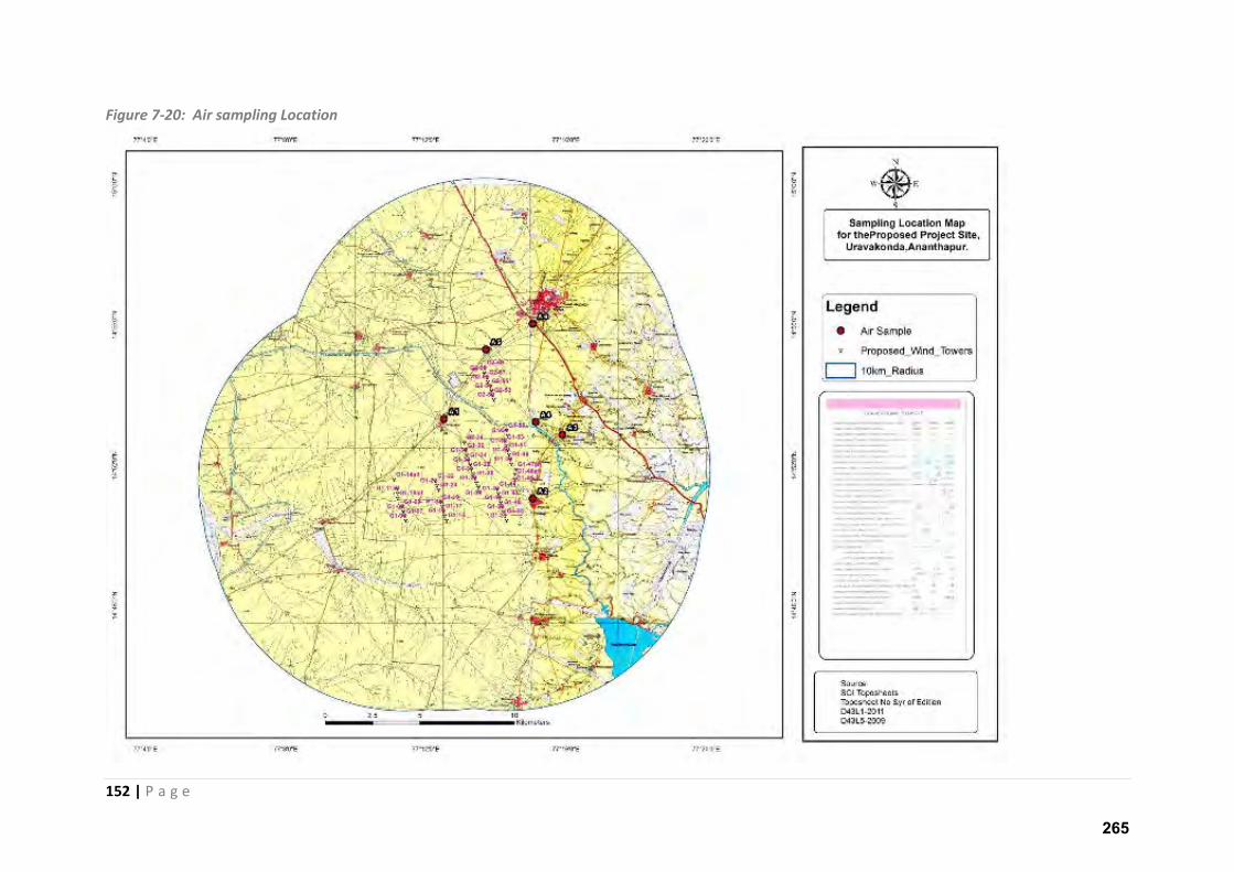
152 | P a g e
Figure 7-20: Air sampling Location
265