Embed Size (px)
Citation preview
ENVE 302
Environmental Engineering Unit Processes
Assist. Prof. Bilge Alpaslan Kocamemi
Marmara University
Department of Environmental Engineering
Istanbul, Turkey
CHAPTER: 14
SLUDGE TREATMENT
1
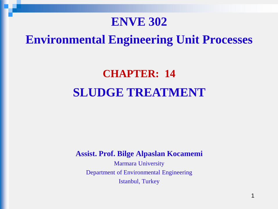
SLUDGE TREATMENT
The constituents removed in wastewater treatment plants:
•screenings
•grit, scum
•solids primary sludge
•biosolids WAS
Screening: all types of organic and inorganic materials large enough to be
removed on bar racks
Grit: heavier inorganic solids
Scum/grease: consists of the floatable materials skimmed from the surface of
primary and secondary settling tanks and from grit chambers
See Table 14.8 (M& E, 4th Ed. p. 1457) : expected solids concentrations from various treatment
operations and processes
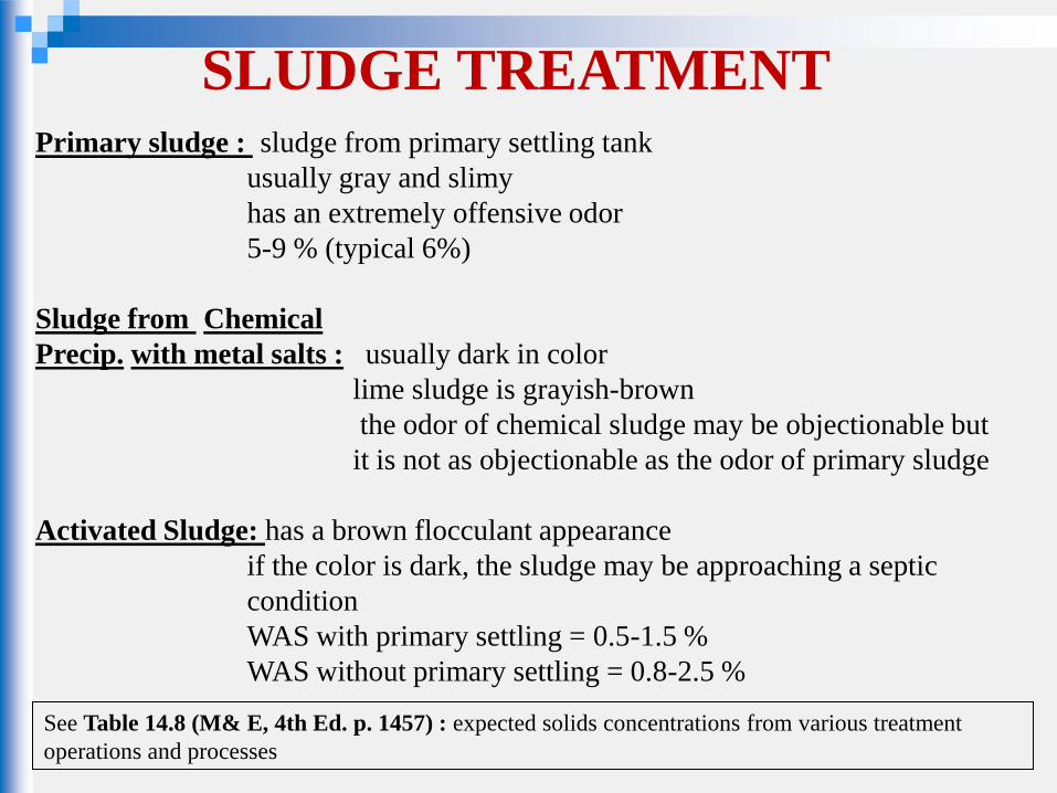
SLUDGE TREATMENT Primary sludge : sludge from primary settling tank
usually gray and slimy
has an extremely offensive odor
5-9 % (typical 6%)
Sludge from Chemical
Precip. with metal salts : usually dark in color
lime sludge is grayish-brown
the odor of chemical sludge may be objectionable but
it is not as objectionable as the odor of primary sludge
Activated Sludge: has a brown flocculant appearance
if the color is dark, the sludge may be approaching a septic
condition
WAS with primary settling = 0.5-1.5 %
WAS without primary settling = 0.8-2.5 %
See Table 14.8 (M& E, 4th Ed. p. 1457) : expected solids concentrations from various treatment
operations and processes
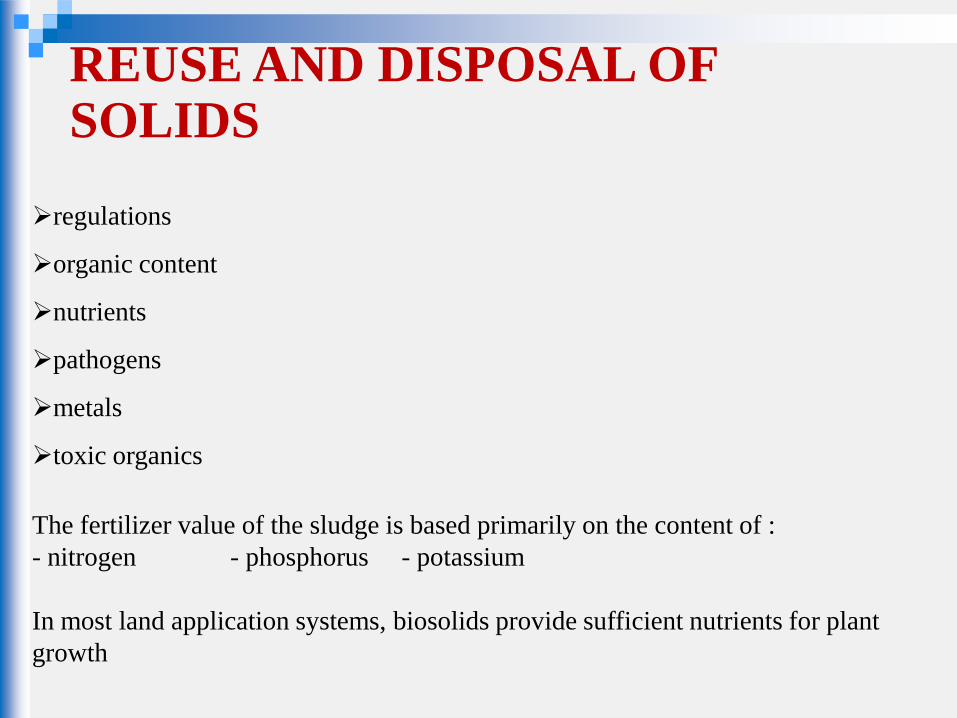
REUSE AND DISPOSAL OF SOLIDS
regulations
organic content
nutrients
pathogens
metals
toxic organics
The fertilizer value of the sludge is based primarily on the content of :
- nitrogen - phosphorus - potassium
In most land application systems, biosolids provide sufficient nutrients for plant
growth
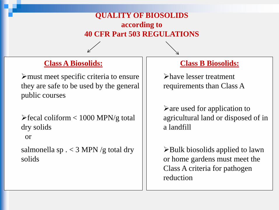
QUALITY OF BIOSOLIDS
according to
40 CFR Part 503 REGULATIONS
Class A Biosolids:
must meet specific criteria to ensure
they are safe to be used by the general
public courses
fecal coliform < 1000 MPN/g total
dry solids
or
salmonella sp . < 3 MPN /g total dry
solids
Class B Biosolids:
have lesser treatment
requirements than Class A
are used for application to
agricultural land or disposed of in
a landfill
Bulk biosolids applied to lawn
or home gardens must meet the
Class A criteria for pathogen
reduction
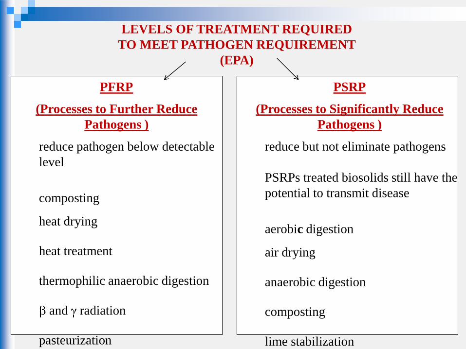
LEVELS OF TREATMENT REQUIRED
TO MEET PATHOGEN REQUIREMENT
(EPA)
PFRP
(Processes to Further Reduce
Pathogens )
reduce pathogen below detectable
level
composting
heat drying
heat treatment
thermophilic anaerobic digestion
and radiation
pasteurization
PSRP
(Processes to Significantly Reduce
Pathogens )
reduce but not eliminate pathogens
PSRPs treated biosolids still have the
potential to transmit disease
aerobic digestion
air drying
anaerobic digestion
composting
lime stabilization
SLUDGE PROCESSING
A) Preliminary Operations
Grinding: large and stringy material contained in the sludge is cut and shredded
into small particles
Screening: coarse solids are removed
Degritting: grit removal
Blending: mixing of sludge (primary-WAS) to produce a uniform mixture to
downstream operations
Storage: allow solids to accumulate during periods when subsequent facilities are
not operating
e.g, night shifts, weekends
SLUDGE PROCESSING
B) Thickening Operations
to increase the solid content of the sludge by removing a portion of liquid fraction
Benefits for subsequent treatment processes:
1. capacity of tanks and equipment decreases
2. quantity of chemicals required for sludge conditioning decreases
3. amount of heat required by digesters decreases
4. for large treatment plants where sludge must be transported a significant
distance , a reduction in sludge volume may result in reduction of pipe size
and pumping cost
Gravity Thickening (about 4 %) Dissolved Air Floatation (3.5-5 % )
Centrifuge (4-6 %) Belt thickener (3-6 %)
Rotary drum thickener (3-6 %)
SLUDGE PROCESSING C)Stabilization Operations
to reduce pathogens
to eliminate offensive odor
to eliminate the potential for putrefaction
Survival of pathogens,release of odor,putrefaction occur when the microorganisms are allowed to flourish in the organic fraction of the sludge to eliminate these nuisance conditions ; biological reduction of volataile content (Digestion, composting) or the addition of chemicals to the solids and biosolids to render them unsuitable for the survival of microorganisms (alkaline stabilization)
SLUDGE PROCESSING
D)Sludge Conditioning to improve the dewaterability characteristics of sludge chemical conditioning results in coagulation of the solids and released of the absorbed water is used in advance of mechanical dewatering (centrifugation, belt filter) polymers iron salts lime
SLUDGE PROCESSING
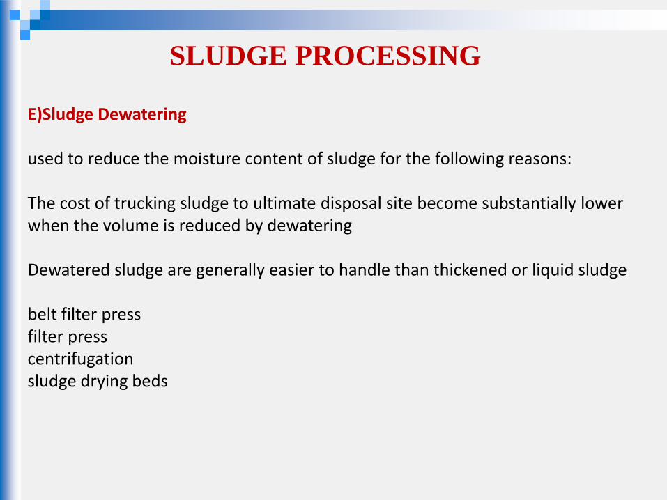
E)Sludge Dewatering used to reduce the moisture content of sludge for the following reasons: The cost of trucking sludge to ultimate disposal site become substantially lower when the volume is reduced by dewatering Dewatered sludge are generally easier to handle than thickened or liquid sludge belt filter press filter press centrifugation sludge drying beds
SLUDGE PROCESSING
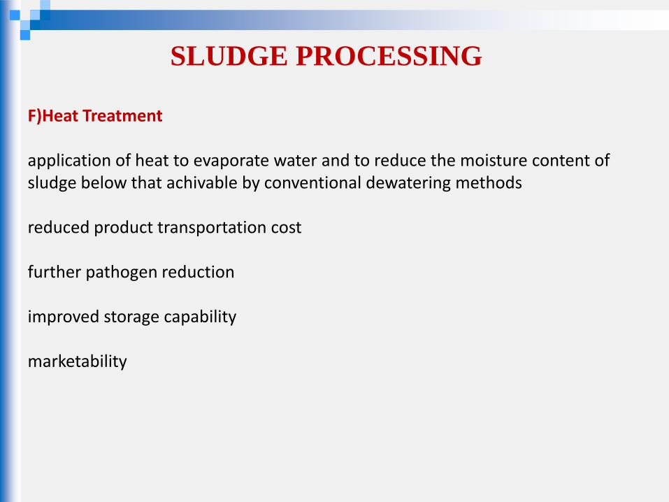
F)Heat Treatment application of heat to evaporate water and to reduce the moisture content of sludge below that achivable by conventional dewatering methods reduced product transportation cost further pathogen reduction improved storage capability marketability
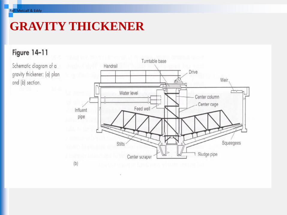
GRAVITY THICKENER
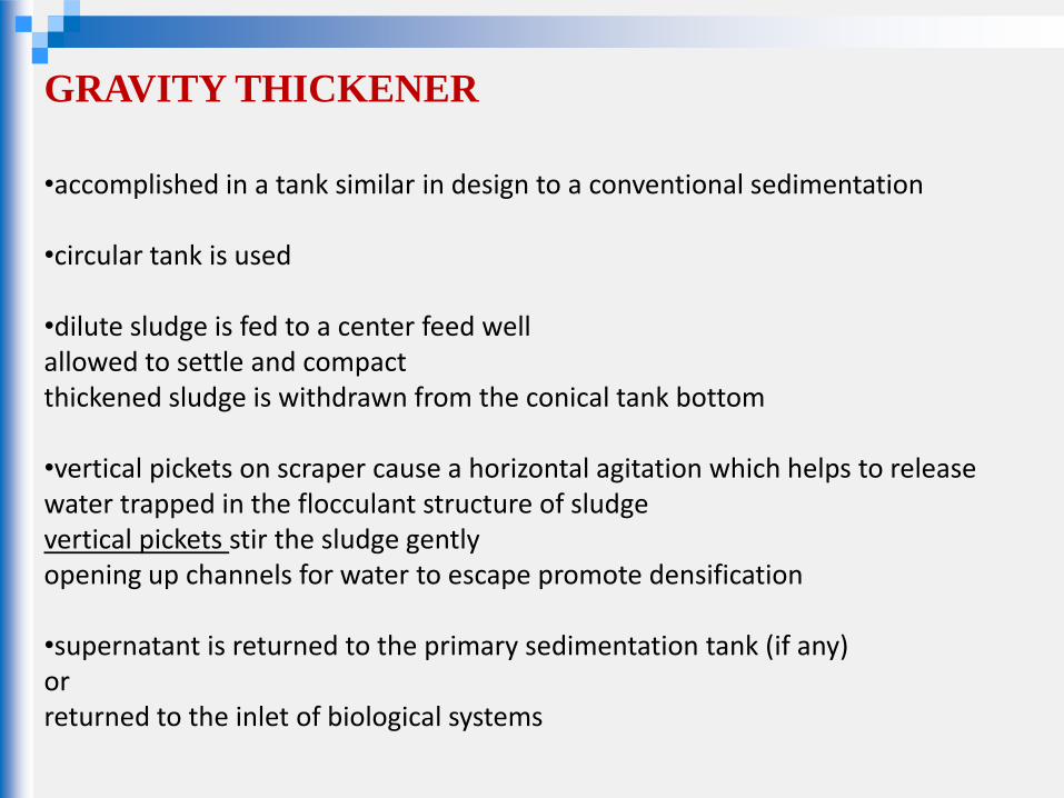
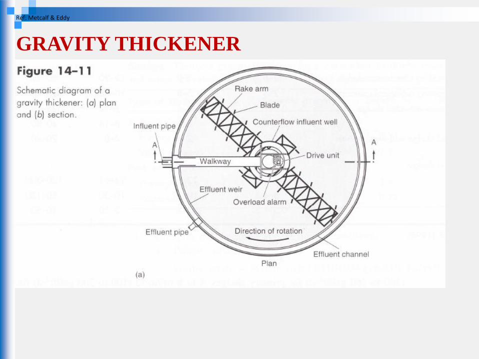
•accomplished in a tank similar in design to a conventional sedimentation •circular tank is used •dilute sludge is fed to a center feed well allowed to settle and compact thickened sludge is withdrawn from the conical tank bottom •vertical pickets on scraper cause a horizontal agitation which helps to release water trapped in the flocculant structure of sludge vertical pickets stir the sludge gently opening up channels for water to escape promote densification •supernatant is returned to the primary sedimentation tank (if any) or returned to the inlet of biological systems
GRAVITY THICKENER
Ref: Metcalf & Eddy
GRAVITY THICKENER
Ref: Metcalf & Eddy
GRAVITY THICKENER
Ref: Metcalf & Eddy
DISSOLVED AIR FLOATATION (DAF)
THICKENING
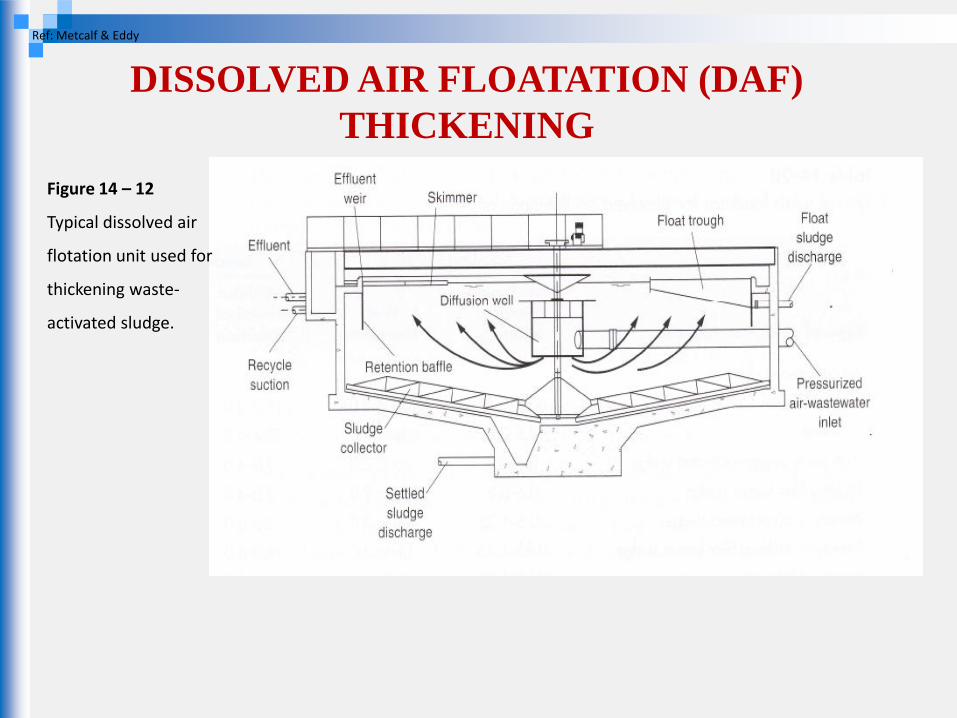
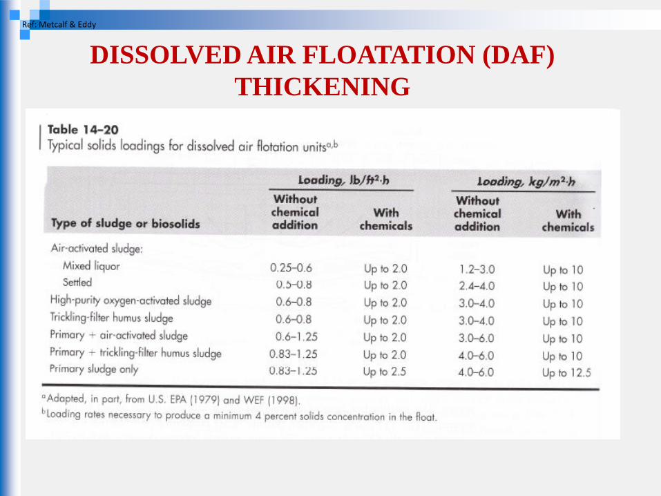
•Air is introduced into the solution that is being held at an elevated pressure •When the solution is depressurized, the dissolved air is released as finely divided bubbles carrying the sludge to the top where it is removed •Important Design Criteria: Air/Solids ratio SVI solids loading rate
DISSOLVED AIR FLOATATION (DAF)
THICKENING
Figure 14 – 12
Typical dissolved air
flotation unit used for
thickening waste-
activated sludge.
Ref: Metcalf & Eddy
DISSOLVED AIR FLOATATION (DAF)
THICKENING
Ref: Metcalf & Eddy
CENTRIFUGAL THICKENING
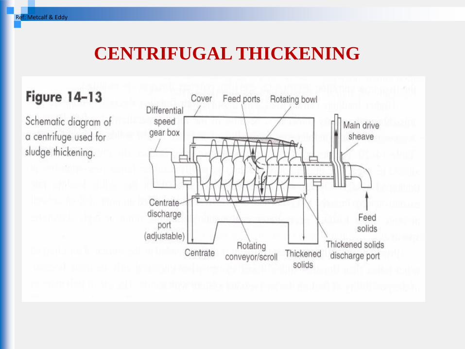
•settling of sludge particles under the influence of centrifugal forces •basic type solid-bowl •sludge is introduced into the unit continuously and the solids concentrate on periphery •high maintenance and power cost •attractive where space is limited •polymer addition to improve performance
CENTRIFUGAL THICKENING
Ref: Metcalf & Eddy
GRAVITY BELT THICKENING
(Gravity Drainage Decks , GDD)
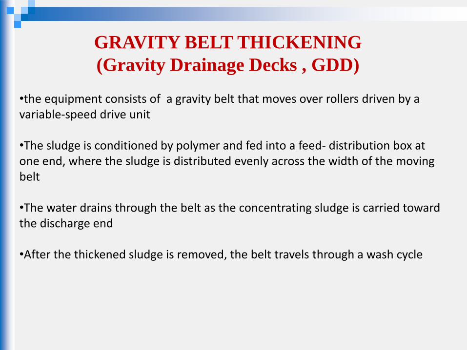
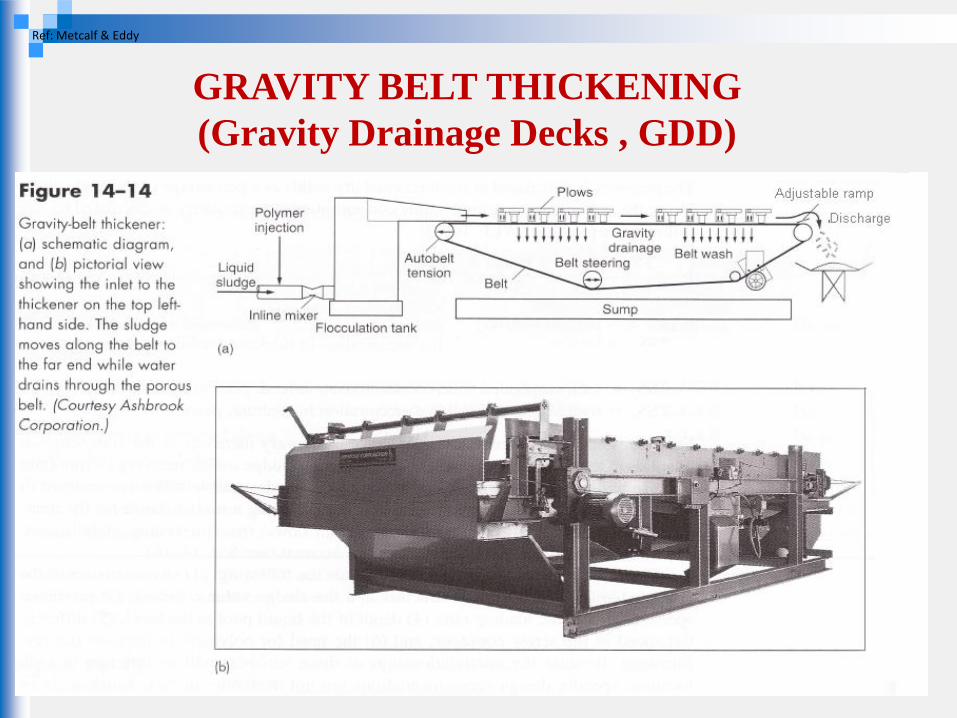
•the equipment consists of a gravity belt that moves over rollers driven by a variable-speed drive unit •The sludge is conditioned by polymer and fed into a feed- distribution box at one end, where the sludge is distributed evenly across the width of the moving belt •The water drains through the belt as the concentrating sludge is carried toward the discharge end •After the thickened sludge is removed, the belt travels through a wash cycle
GRAVITY BELT THICKENING
(Gravity Drainage Decks , GDD)
Ref: Metcalf & Eddy
GRAVITY BELT THICKENING
(Gravity Drainage Decks , GDD)
Ref: Metcalf & Eddy
ROTARY DRUM THICKENING
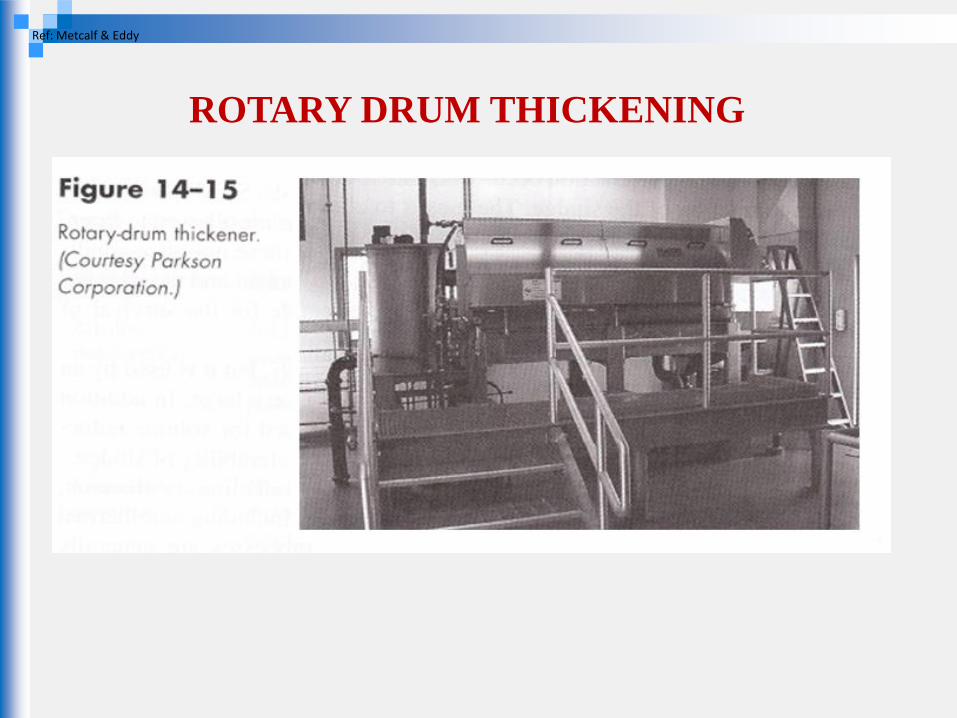
•consist of a conditioning system (polymer feed system) and rotating cylindrical screens •polymer is mixed with dilute sludge •the conditioned sludge is then passed to a rotating-screen drum which separate the flocculated solids from the water
ROTARY DRUM THICKENING
Ref: Metcalf & Eddy

ROTARY DRUM THICKENING
Ref: Metcalf & Eddy
SLUDGE STABILIZATION
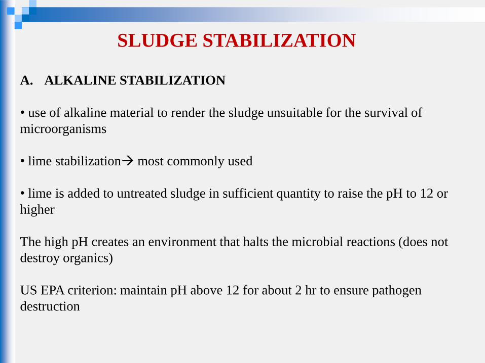
A. ALKALINE STABILIZATION
• use of alkaline material to render the sludge unsuitable for the survival of
microorganisms
• lime stabilization most commonly used
• lime is added to untreated sludge in sufficient quantity to raise the pH to 12 or
higher
The high pH creates an environment that halts the microbial reactions (does not
destroy organics)
US EPA criterion: maintain pH above 12 for about 2 hr to ensure pathogen
destruction
SLUDGE STABILIZATION
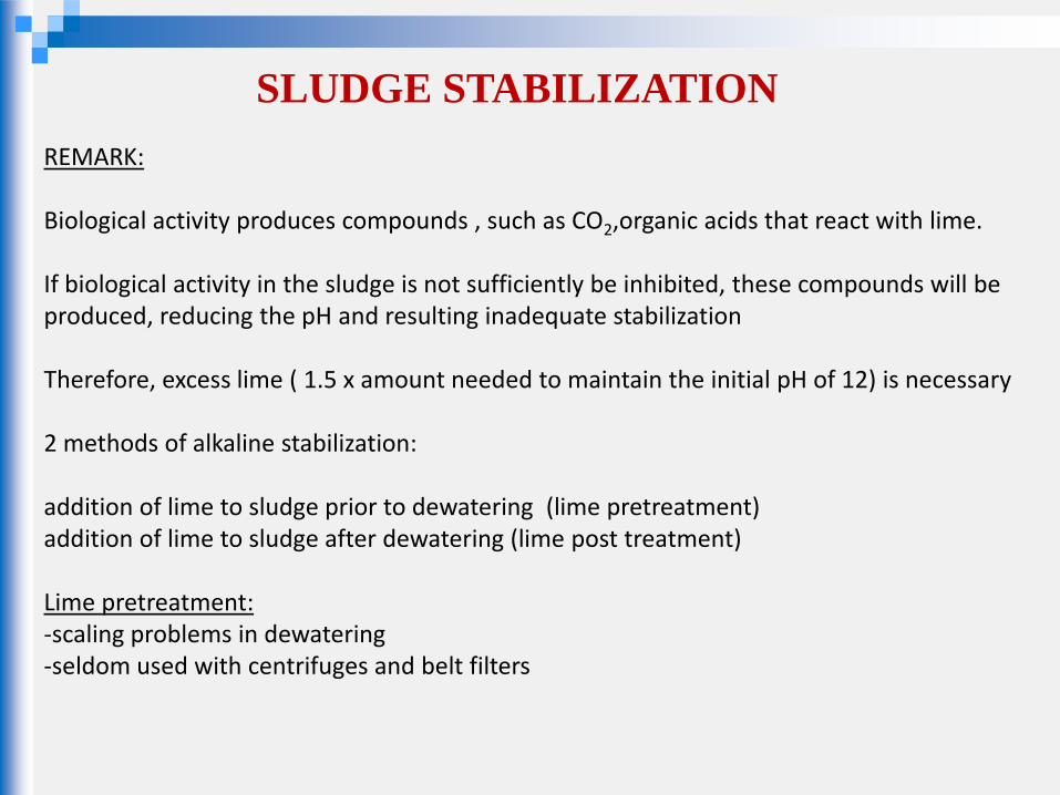
REMARK: Biological activity produces compounds , such as CO2,organic acids that react with lime. If biological activity in the sludge is not sufficiently be inhibited, these compounds will be produced, reducing the pH and resulting inadequate stabilization Therefore, excess lime ( 1.5 x amount needed to maintain the initial pH of 12) is necessary 2 methods of alkaline stabilization: addition of lime to sludge prior to dewatering (lime pretreatment) addition of lime to sludge after dewatering (lime post treatment) Lime pretreatment: -scaling problems in dewatering -seldom used with centrifuges and belt filters
SLUDGE STABILIZATION
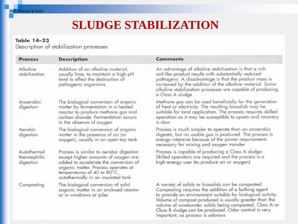
Ref: Metcalf & Eddy
SLUDGE STABILIZATION
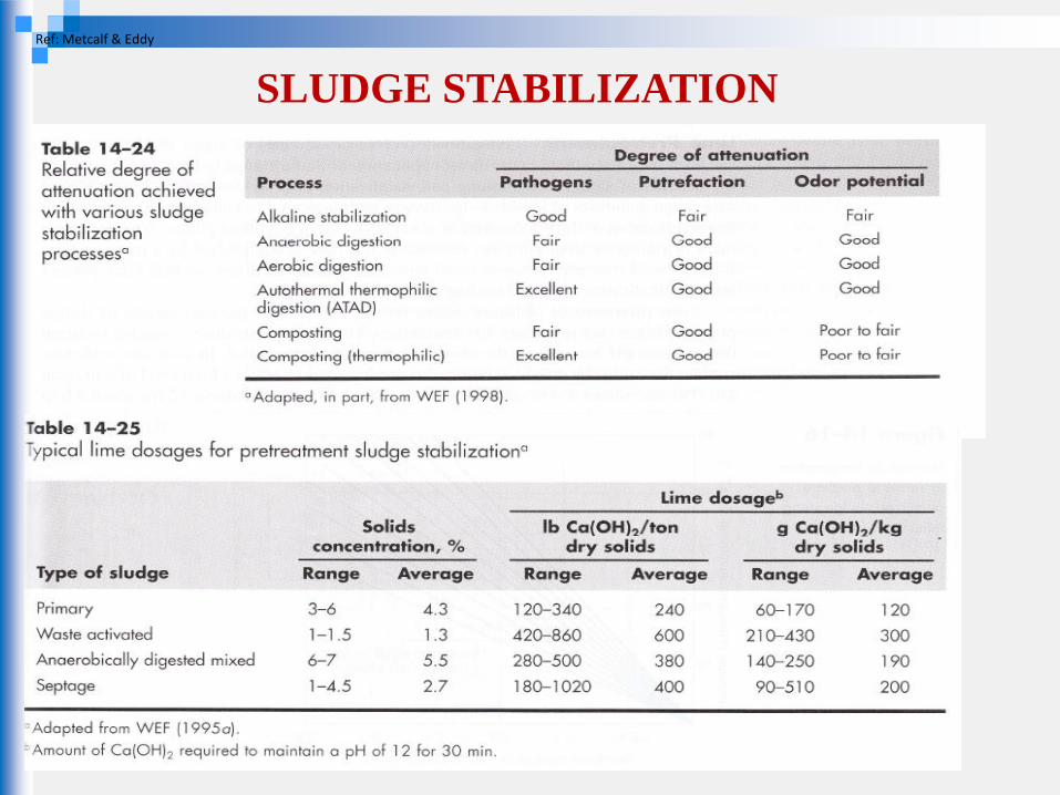
Ref: Metcalf & Eddy
SLUDGE STABILIZATION
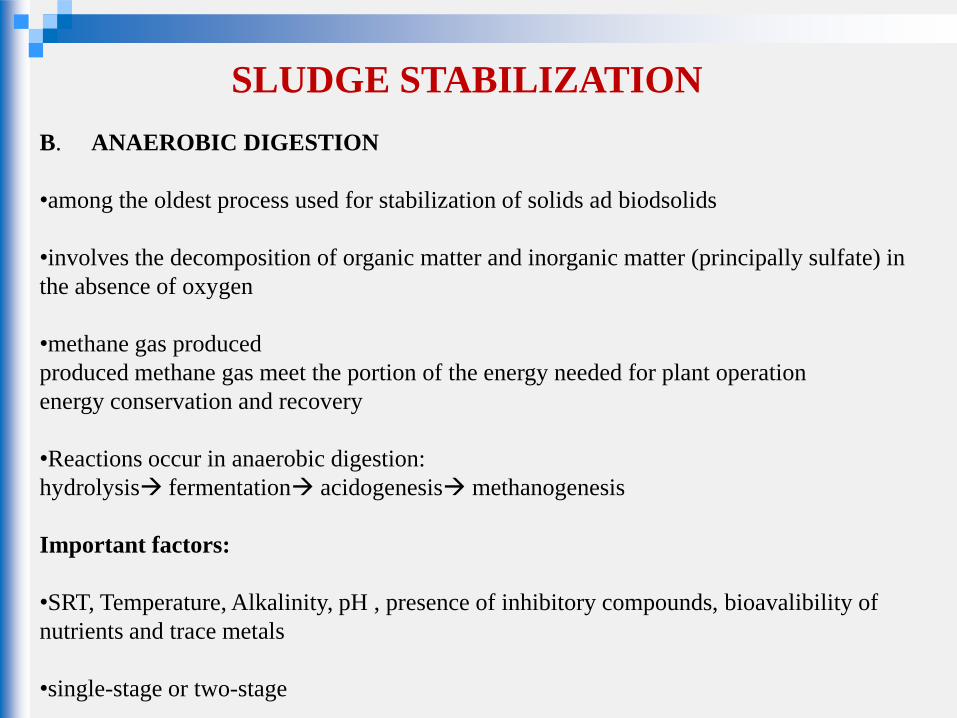
B. ANAEROBIC DIGESTION
•among the oldest process used for stabilization of solids ad biodsolids
•involves the decomposition of organic matter and inorganic matter (principally sulfate) in
the absence of oxygen
•methane gas produced
produced methane gas meet the portion of the energy needed for plant operation
energy conservation and recovery
•Reactions occur in anaerobic digestion:
hydrolysis fermentation acidogenesis methanogenesis
Important factors:
•SRT, Temperature, Alkalinity, pH , presence of inhibitory compounds, bioavalibility of
nutrients and trace metals
•single-stage or two-stage
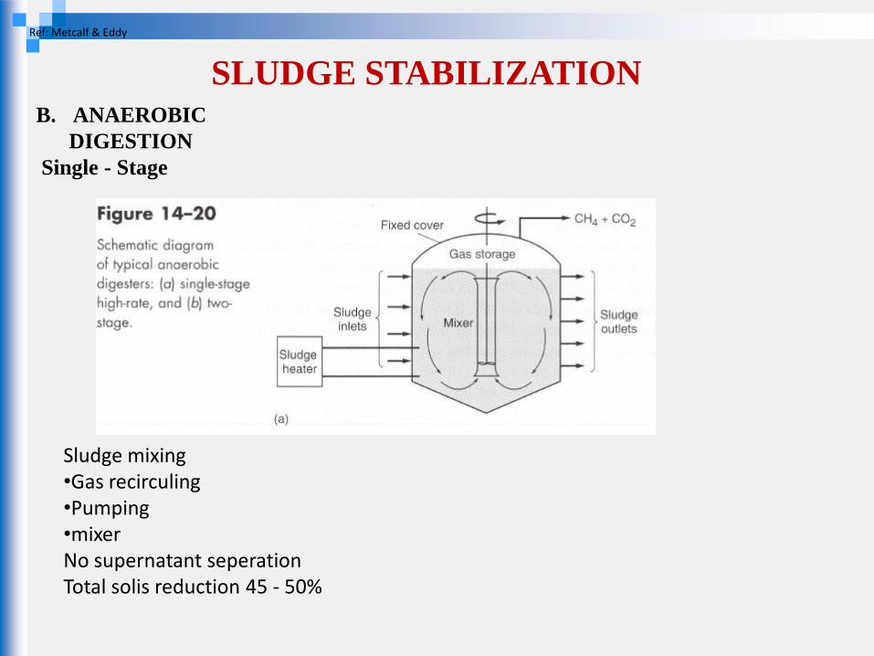
SLUDGE STABILIZATION B. ANAEROBIC
DIGESTION
Single - Stage
Ref: Metcalf & Eddy
Sludge mixing •Gas recirculing •Pumping •mixer No supernatant seperation Total solis reduction 45 - 50%
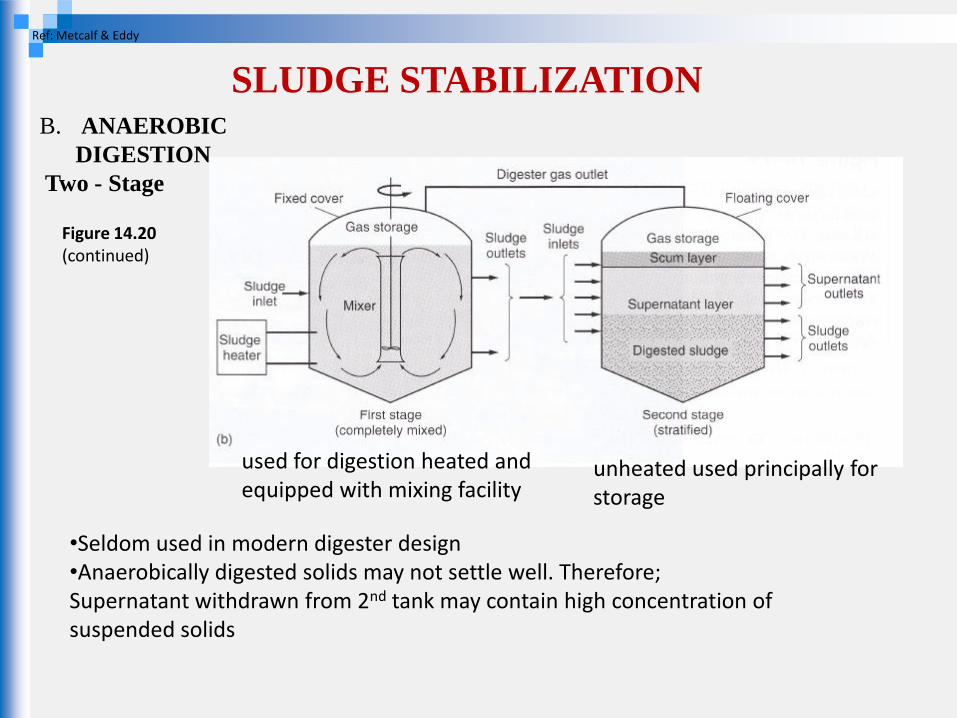
SLUDGE STABILIZATION B. ANAEROBIC
DIGESTION
Two - Stage
Ref: Metcalf & Eddy
•Seldom used in modern digester design •Anaerobically digested solids may not settle well. Therefore; Supernatant withdrawn from 2nd tank may contain high concentration of suspended solids
Figure 14.20 (continued)
used for digestion heated and equipped with mixing facility
unheated used principally for storage
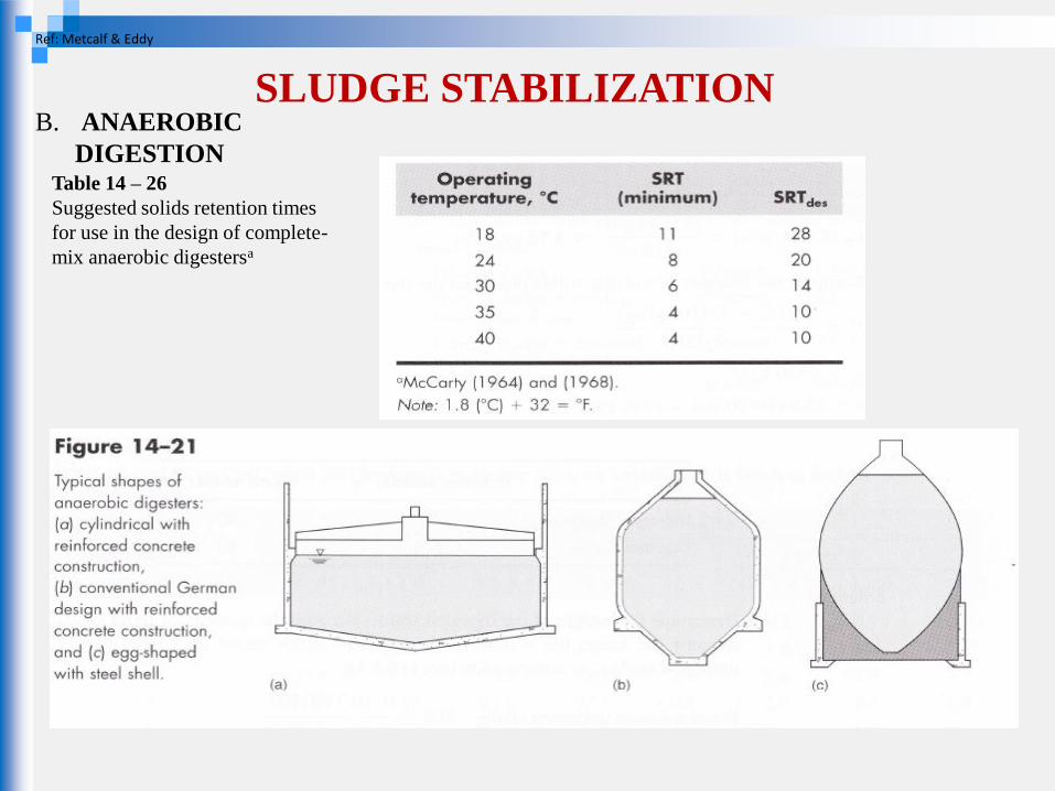
SLUDGE STABILIZATION
Ref: Metcalf & Eddy
Table 14 – 26
Suggested solids retention times
for use in the design of complete-
mix anaerobic digestersa
B. ANAEROBIC
DIGESTION
SLUDGE STABILIZATION
Ref: Metcalf & Eddy
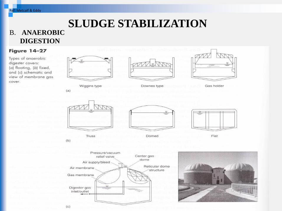
B. ANAEROBIC
DIGESTION
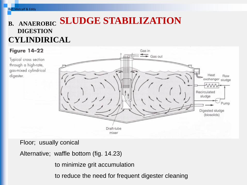
CYLINDIRICAL
DIGESTER
Floor; usually conical
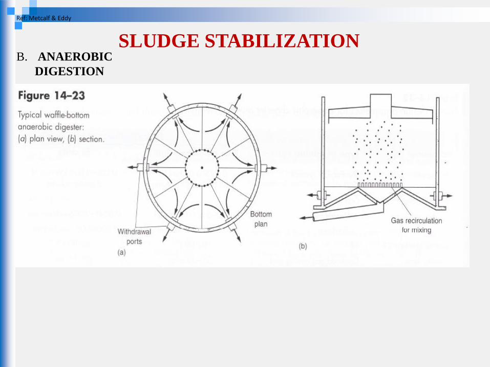
Alternative; waffle bottom (fig. 14.23)
to minimize grit accumulation
to reduce the need for frequent digester cleaning
SLUDGE STABILIZATION
Ref: Metcalf & Eddy
B. ANAEROBIC
DIGESTION

SLUDGE STABILIZATION
Ref: Metcalf & Eddy
B. ANAEROBIC
DIGESTION
SLUDGE STABILIZATION Ref: Metcalf & Eddy
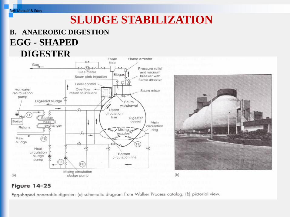
B. ANAEROBIC DIGESTION
EGG - SHAPED
DIGESTER
SLUDGE STABILIZATION Ref: Metcalf & Eddy
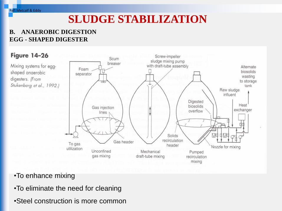
•To enhance mixing
•To eliminate the need for cleaning
•Steel construction is more common
B. ANAEROBIC DIGESTION
EGG - SHAPED DIGESTER
SLUDGE STABILIZATION
Ref: Metcalf & Eddy
B. ANAEROBIC
DIGESTION
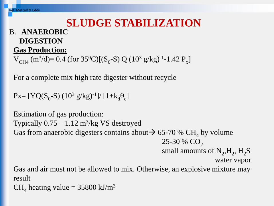
Gas Production:
VCH4 (m3/d)= 0.4 (for 350C)[(S0-S) Q (103 g/kg)-1-1.42 Px]
For a complete mix high rate digester without recycle
Px= [YQ(S0-S) (103 g/kg)-1]/ [1+kd c]
Estimation of gas production:
Typically 0.75 – 1.12 m3/kg VS destroyed
Gas from anaerobic digesters contains about 65-70 % CH4 by volume
25-30 % CO2
small amounts of N2,H2, H2S
water vapor
Gas and air must not be allowed to mix. Otherwise, an explosive mixture may
result
CH4 heating value = 35800 kJ/m3
SLUDGE STABILIZATION
Ref: Metcalf & Eddy
B. ANAEROBIC
DIGESTION
SLUDGE STABILIZATION
C. AEROBIC DIGESTION
•similar to activated sludge process
•as the supply of available substrate (food) is depleted, the microorganisms begin
to consume their own protoplasm .
•when energy is obtained from cell tissue, the microorganisms are said to be in the
endogenous phase
Only 75-80 % of the cell tissue can be oxidized
Remaining 20-25 % is composed of inert components that are not biodegradable
Nonbiodegradable VSS will remain in final product from aerobic digestion
SLUDGE DEWATERING
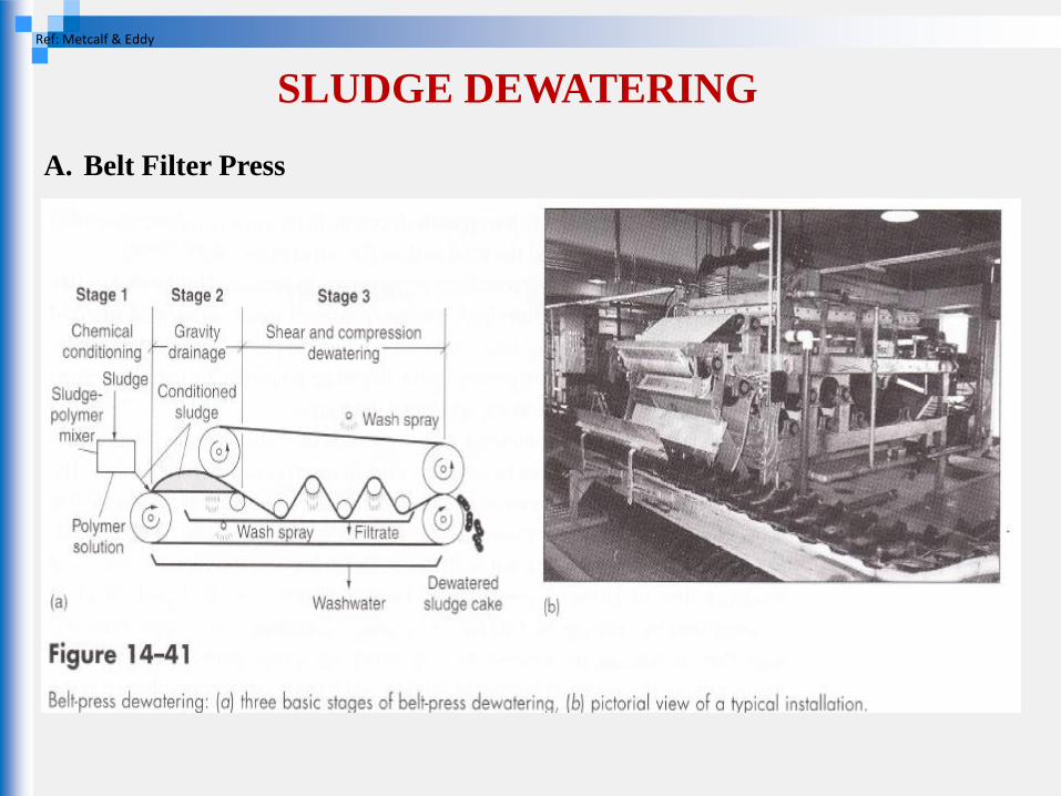
A. Belt Filter Press
In most types of belt filter press,
•conditioned sludge is first introduced on a gravity drainage section where it is
allowed to thicken
•In this section majority of the free water is removed from the sludge by gravity
•Following to gravity drainage, pressure is applied in a low pressure section,
where sludge is squeezed between opposing porous cloth belts
•Low pressure section is followed by a high pressure section where the sludge is
subjected to shearing forces as the belts pass through a series of rollers
SLUDGE DEWATERING
A. Belt Filter Press
Ref: Metcalf & Eddy
SLUDGE DEWATERING
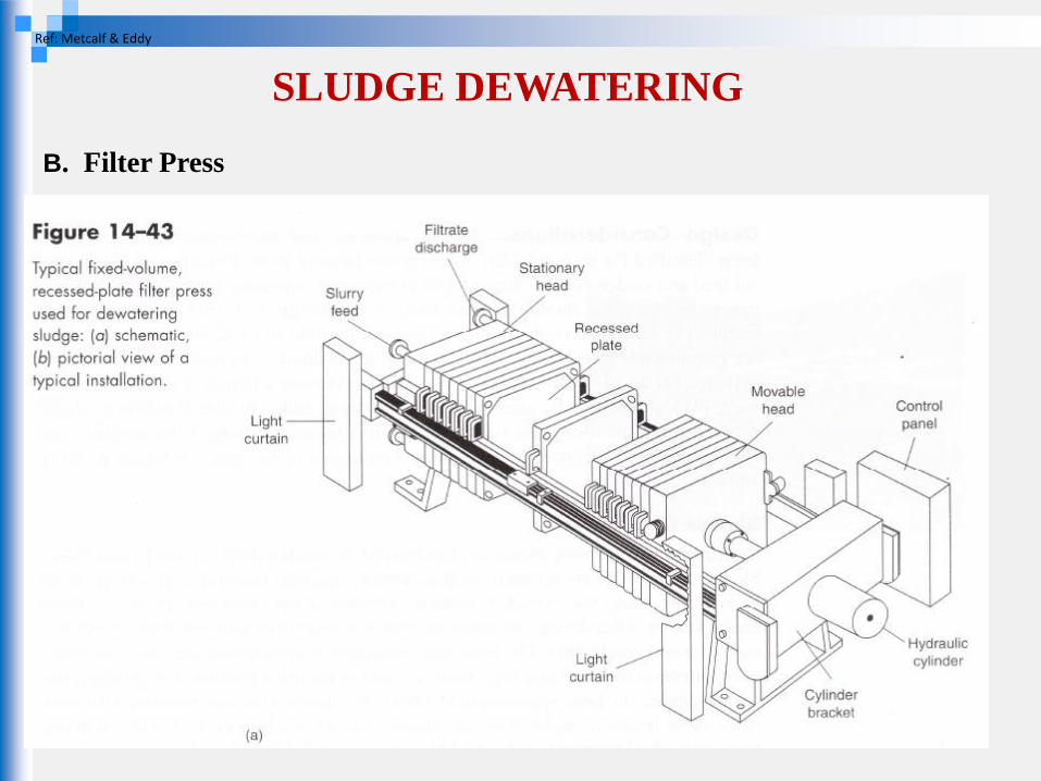
B. Filter Press
•dewatering is achieved by forcing the water from the sludge under high pressure
•High concentrations of cake solids can be achieved
•high chemical cost, limitations for filter cloth life
SLUDGE DEWATERING
B. Filter Press
Ref: Metcalf & Eddy
SLUDGE DEWATERING
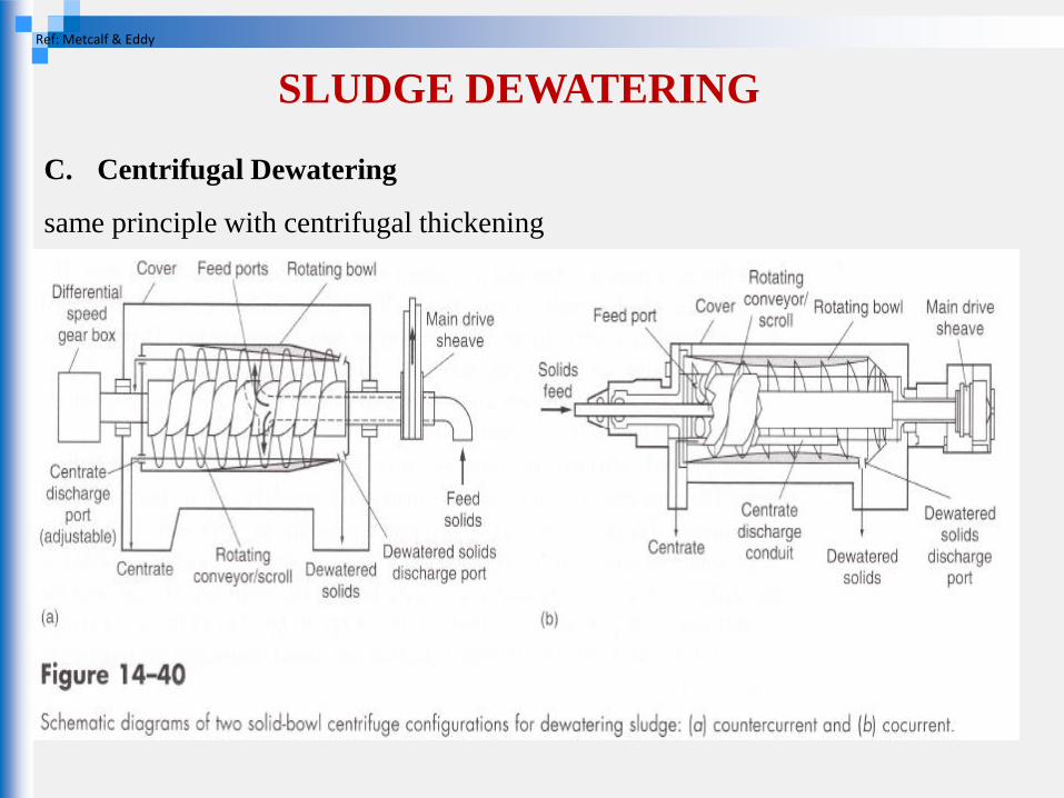
C. Centrifugal Dewatering
same principle with centrifugal thickening
Ref: Metcalf & Eddy
SLUDGE DEWATERING
D. Sludge Drying Beds
sludge is placed on the bed in a 200 to 300 mm layer and allowed to dry
sludge dewaters by drainage through the sludge mass and evaporation from the
surface exposed to atmosphere
major advantage low cost
major disadvantage large space requirement, effects of climatic changes on
drying characteristics , insects, potential odor


![[XLS] · Web view1 302 2 302 3 302 4 302 5 302 6 363 7 363 8 302 9 302 10 307 11 302 12 302 13 223244 14 302 15 302 16 224 17 302 18 302 19 302 20 302 21 302 22 23 24 25 26 302 27](https://img.pdfslide.us/doc/110x75/5b00c3a37f8b9a952f8d6104/xls-view1-302-2-302-3-302-4-302-5-302-6-363-7-363-8-302-9-302-10-307-11-302-12.jpg)