Embed Size (px)
Citation preview

Entropy-Based Visual Servoing
Amaury Dame, Eric Marchand
Abstract— In this work we propose a new way to achievevisual servoing using directly the information (as defined byShannon) of the image. A metric derived from informationtheory, mutual information, is considered. Mutual informationis widely used in multi-modal image registration (medical appli-cations) since it is insensitive to changes in the lighting conditionand to a wide class of non-linear image transformation. In thispaper mutual-information is used as a new visual feature forvisual servoing and allows us to build a new control law tocontrol the 6 dof of the robot. Among various advantages, thisapproach does not require any matching nor tracking step, isrobust to large illumination variation and allows to consider,within the same task, different image modalities. Experimentsthat demonstrate these advantages conclude the paper.
I. I NTRODUCTION
A. Motivations
Visual servoing consists in using the information providedby a vision sensor to control the movements of a dynamicsystem [2]. This approach requires to extract information(usually geometric features) from the image in order todesign the control law. Robust extraction and real-timespatio-temporal tracking of these visual cues [9] is a nontrivial task and also one of the bottlenecks of the expansionof visual servoing.
In [4], it has been shown that no other information than theimage intensity (the pure image signal) can be considered tocontrol the robot motion and that these difficult tracking andmatching processes can be totally removed. Although veryefficient, this approach is sensitive to light variation.
In this paper, we propose a new approach that no longerrelies on geometrical features [2] nor on pixels intensity [4]but use directly the information (entropy) contained in theimage signal. More precisely we will consider mutual infor-mation [16]. Being closer from the signal, we will show thatthis new approach
• is robust to very important light variations (see Fig-ure 1a),
• is robust to important occlusions,• is able to consider different image modalities (see
Figure 1b).
B. Overview and related works
Classically, to achieve a visual servoing task, a set ofvisual features has to be selected from the image allowing tocontrol the desired degrees of freedom (dof). A control lawhas also to be designed so that these visual featuress reach adesired values∗, leading to a correct realization of the task.The control principle is thus to regulate to zero the error
Amaury Dame is with CNRS, IRISA, Lagadic team, Rennes, France. E.Marchand is with INRIA Rennes - Bretagne Atlantique, IRISA,Lagadicteam, Rennes, France. This work is supported by DGA under contributionto student [email protected].
(a) (b)
Fig. 1. The visual servoing scheme considering mutual informationas visual feature is able to handle very important lighting variation (a).Furthermore, different modalities can be considered for images acquisition(b). First row is desired image while second row shows the final imageacquired by the robot. In (a), the positioning task was correctly achieveddespite an important modification of the lighting conditionbetween thelearning step and the execution of the task (see section IV-Afor details).In (b) the learning step was done using a map while the servoing task wascarried out on the corresponding aerial images. It is nevertheless possibleto carry out a trajectory tracking task (see section IV-B).
vector s − s∗. To build this control law, the knowledge of
the interaction matrixLs, that links the time variation ofs tothe camera instantaneous velocityv, is usually required [2].
Nevertheless, the key point of this approach is the choiceof the visual featuress. With a vision sensor providing 2Dmeasurementsx(rk) (whererk is the camera pose at timek), potential visual featuress are numerous, since 2D data(coordinates of feature points in the image, moments, ...)as well as 3D data provided by a localization algorithmexploiting the extracted 2D features can be considered. Ifthe choice ofs is important, it is always designed fromvisual measurementsx(rk). A robust extraction, matching(betweenx(rk) and the desired measurementsx
∗ = x(r∗))and real-time spatio-temporal tracking (betweenx(rk−1) andx(rk)) have proved to be difficult, as testified by the abundantliterature on the subject. These tracking and matching pro-cesses are even more difficult when acquisition configurationis modified during the execution of the task or if two differentsensors or acquisition modalities are considered.
Recently different approaches have been proposed to getover these issues by considering no longer geometric featuresbut the image itself or a function of the image. Consider-ing the whole image as a feature avoids the tracking andmatching process. Following this way, various approacheshave been presented. [5], [10] consider the full image butin order to reduce the dimensionality of image data they
consider an eigenspace decomposition of the image. Thecontrol is then performed directly in the eigenspace whichrequires the off-line computation of this eigenspace (usinga principal component analysis) and then, for each newframe, the projection of the image on this subspace. Tocope with these issues a way to compute the interactionmatrix related to the luminance under temporal luminanceconstancy case has been proposed in [4]. In that case, theerror to be regulated is nothing but the sum of squareddifferences (SSD) between the current and the desired images‖ I − I
∗ ‖. Such approach is nevertheless quite sensitiveto illumination variations (although using a more complexillumination model in some particular cases is possible [3]).[7] also considers the pixels intensity. This approach isbased on the use of kernel methods that lead to a highdecoupled control law. However, only the translations andthe rotation around the optical axis are considered. Anotherapproach that does not require tracking nor matching hasbeen proposed in [1]. It models collectively feature pointsextracted from the image as a mixture of Gaussian andtries to minimize the distance function between the Gaussianmixture at current and desired positions. Simulation resultsshow that this approach is able to control the 3 dof of therobot. However, note that an image processing step is stillrequired to extract the current feature points.
As stated considering image intensity is quite sensitiveto modification of the environment. To solve problems dueto illumination changes or multi-modal servo, informationcontained in the images is considered and no more directlythe luminance. The feature is the mutual information definedby Shannon in [12]. The mutual information (built from theentropy) of two random variables is a quantity that measuresthe mutual dependence of the two variables. Considering twoimages, the higher the mutual information is, the better is thealignment between the two images. Considering informationcontained in the image and not the image itself allows to beindependent from perturbation or from the image modality.Such approach has been widely used for multi-modal medicalimage registration [16] [8] and more recently in tracking [6].
The remainder of this paper is organized as follows. Insection II a background on information theory is presentedand mutual information is formulated related to images.The resulting control law is presented in section III. Finallyexperiments on a 6 dof robot are presented in section IV.
II. I NFORMATION THEORY
The feature considered in previous works was the SSDwhich only deals with quasi identical images. To extendcapabilities of the servoing task, information between imagesis considered. In this section entropy, joint entropy andmutual information are generally defined to end with theuse of mutual information on images.
A. Mutual information
1) Entropy: To understand mutual information, a briefdefinition of entropy of a random variable is required. TheentropyH(X) of a random variableX (image, signal...) ismostly used in signal compression: it defines the theoreticalnumber of bits needed to encode a random variable. Ifx are
(a)
0.46 0.48 0.5 0.52 0.54 0.56 0.58 0.6
50
-5 5
0-5
0.45
0.5
0.55
0.6
MI=f(tx,ty)
tx (px)ty (px)
(c)
(b)
3700 3800 3900 4000 4100 4200 4300 4400
100
-10 10
0-10
3600
3800
4000
4200
4400
SSD=f(tx,ty)
tx (px)ty (px)
(c)
Fig. 2. Illumination changes. Value of the mutual information (c) and SSD(d) by translating image (a) in the image space(tx, ty) and comparing itwith image (b) from the same position with illumination changes. SSD hasa minimum in(tx, ty) = (−2,−2) while mutual information has a correctmaximum in(tx, ty) = (0, 0).
the possible values ofX andpX(x) = P (X = x), then theentropyH(X) is given by:
H(X) = −∑
x
pX(x) log2 (pX(x)) . (1)
By definition 0 log2(0) = 0. For legibility issueslog will beused aslog2. The more valuesx are equally probable themore entropyH(X) is bigger.
2) Joint entropy: Following the same idea joint entropyH(X, Y ) of two random variablesX andY can be definedas:
H(X, Y ) = −∑
x,y
pX,Y (x, y) log (pX,Y (x, y)) (2)
wherex andy are respectively the possible values ofX andY , pX,Y (x, y) = P (X = x∩Y = y) is the joint probabilityof the valuesx andy. Typically the joint entropy defines thetheoretical number of bits needed to encode a joint systemof two random variables. At first sight finding the minimumof this entropy can be seen as an alignment method. Butthe dependencies on entropies ofX and Y is a problem.In fact by adding a variable to another it is impossibleto make the global entropy decrease, somin(H(X, Y )) =max(H(X), H(Y )).
For example considering a signalX , if a signalY = X isadded to the system, the system will keep the same entropyH(X, Y ) = H(Y ). Y does not add variability to the system.Now if we add a constant signalY , the system keep the sameentropy for the same reason. But in the second situation thetwo signals cannot be considered as aligned.
3) Mutual information: The definition of mutual infor-mation solve the above mentioned problem [12]. Mutualinformation of two random variablesX and Y is given bythe following equation:
MI(X, Y ) = H(X) + H(Y ) − H(X, Y ). (3)
Using equations (1) and (2) it yields to:
MI(X, Y ) =∑
x,y
pxy(x, y) log
(
pxy(x, y)
px(x)py(y)
)
(4)

As shown in this equation, the dependencies on the entropiesare suppressed by the difference between random variable’sentropies and joint entropy. Mutual information is thenthe quantity of information shared between two randomvariables. If mutual information is maximized, then the twosignals are aligned. The advantage of this function compareto SSD is that no linear relation is needed between thetwo signals [15]. To illustrate possibilities of alignment,mutual information has been computed applying a translationto images of different illumination conditions (Figure 2).A maximum at zero translation (the alignment position) isshown using mutual information whereas the SSD leads toan incorrect result.
B. Mutual information on images
In previous section mutual information has been definedfor every kind of random variables. Now our interest is touse it to compare two images.
If I = I(r) represents the image at the current poser ofthe camera and ifI∗ = I(r∗) is the image at the desiredposer
∗ (r and r∗ both elements ofR3 × SO(3)), using
previous equations, mutual information of two imagesI andI∗ is given by:
MI (I(r), I∗) =∑
i,j
pij(i, j, r) log
(
pij(i, j, r)
pi(i, r)pj(j)
)
(5)
where i and j are respectively the pixel luminances al-lowed in the imagesI and I
∗. Typically the number ofgray levelsNcI and NcI∗ of the imagesI and I
∗ are 256(
(i, j) ∈ [0; 255]2 ⊂ Z2)
. pi(i, r) andpj(j) are respectivelythe probability of the luminancei and j in the imagesIandI
∗. Knowing thatr∗ is constant, for clarity issue, in theremainder of this paperpj(j) and pij(i, j, r) will respec-tively denotepj(j, r
∗) and pij(i, j, r, r∗). The probabilities
can simply be computed as a normalized histogram of theimages:
pi(i, r) =1
Nx
∑
x
δ0 (i − I(x, r)) (6)
pj(j) =1
Nx
∑
x
δ0 (j − I∗(x)) (7)
whereNx is the number of pixels in the region of interestof the image,δ(x) is a Kronecker’s function:δ(x) = 1 forx = 0 elseδ(x) = 0.
pij(i, j, r) is the joint probability of the two luminancesiandj computed using a normalization of the joint histogramof the images:
pij(i, j, r) =1
Nx
∑
x
h(i, j, r) (8)
=1
Nx
∑
x
δ0 (i − I(x, r)) δ0 (j − I∗(x))
whereh(i, j, r) is the joint intensity histogram of the twoimages.
Considering every gray levels of the images, mutual in-formation has been computed using translation around thezero position. As shown in Figure 3, the maximum is very
1 1.5 2 2.5 3 3.5 4 4.5 5
10
0
-10 10
0-10
1
2
3
4
5
tx (px)ty (px)
0.35 0.4 0.45 0.5 0.55 0.6 0.65 0.7 0.75
100
-10 10
0-10
0.3 0.4 0.5 0.6 0.7 0.8
tx (px)ty (px)
0.144 0.146 0.148 0.15 0.152 0.154 0.156 0.158 0.16
0
-100
-10
0.14
0.15
0.16
tx (px)ty (px)
0.11 0.111 0.112 0.113 0.114 0.115 0.116
0
-100
-10
0.11 0.111 0.112 0.113 0.114 0.115 0.116
tx (px)ty (px)
Fig. 3. Influence of the bin-size of the histogramNc. Value of the mutualinformation between the image of the first column and its translation in theimage space(tx, ty). Second column: original mutual information (Nc =256), third column: mutual information with a bin-size of histogramNc =8. First row: without noise, second row: adding Gaussian noise to the imageand its translation.
sharp giving an accurate result. However, the shape of thecost function outside the maximum is quite planar, causingpossible artefacts in case of noise.
To overcome this problem, the in-Parzen windowing for-mulation of MI is used [13]. The luminances of the twoinitial images are divided to fit in the desired space of values[0; Nc − 1] ⊂ R where Nc is the new bin-size of thehistogramh. Let I andI∗ represent the new images:
I(x) = I(x)Nc
NcI
I∗(x) = I∗(x)
Nc
NcI∗
. (9)
The only difference concerning the equation of mutualinformation (Eq. 5) is that the summation is no more on256 but on Nc values. The principal changes occur in thecomputation of the marginal and joint probability. To keepmost information despite quantifying, a B-spline functionisused:
pi(i, r) =1
Nx
∑
x
φ[
i − I(x, r)]
(10)
pj(j) =1
Nx
∑
x
φ[
j − I∗(x)]
(11)
pij(i, j, r) =1
Nx
∑
x
φ[
i − I(x, r)]
φ[
j − I∗(x)]
(12)
A detailed description of B-spline functions is given byUnseret al. in [14] but interesting properties of B-spline arerecalled here: the integral of the function being1, the resultdoes not have to be renormalized and the computation of thederivatives is easily obtained. To keep a low computationalcost, in the following experiments a B-spline of order 2 hasbeen selected:
φ(t) =
t + 1 if t ∈ [−1, 0]
−t + 1 if t ∈ [0, 1]
0 otherwise
(13)
In Figure 3 a computation of mutual information is pre-sented using a histogram’s bin-size ofNc = 256 and onewith Nc = 8 on two identical images applying a translation.It shows that the maximum is wider with a smallerNc addingnoise robustness to the optimisation problem.
III. V ISUAL SERVOING BASED ONMUTUAL
INFORMATION
Having a robust alignment function, now the goal is touse it to reach the desired poser∗ with the camera i.e.to maximize information mutual to the current and desiredframe. In this section to respect convention of minimizationthe opposite of mutual information is used:
r∗ = min
r(−MI(I(r), I∗)) . (14)
This alignment problem brings us to an optimization prob-lem. Having the camera at current positionrt, the gradientof the cost function is used to findv = (υ, ω) the velocityvector in the Cartesian space applied to the camera to reachpositionrt+1 corresponding to a higher mutual information.Each minimization step can be written as follows:
rt+1 = rt ⊕ v (15)
where ”⊕” defines the operator that applies a velocity toa pose. For the same reasons as in [4] the optimizationmethod chosen in the following experiments is a Levenberg-Marquardt like approach which allows to smoothly pass fromGauss-Newton to Steepest Descent method, depending onhow far is the minimum:
v = −λ(H + µdiagH)−1G
⊤ (16)
where G ∈ R1×6 and H ∈ R
6×6 are respectively theGradient and the Hessian of the cost function. As explainedin [6], from (5) the Gradient can be computed this way:
G = −∂MI(I(r), I∗)
∂r
= −∑
i,j
∂pij
∂r
(
1 + log
(
pij
pi
))
. (17)
The derivative of the joint probability∂pij/∂r ∈ R1×6 is
computed using:
∂pij
∂r=
1
Nx
∑
x
∂φ
∂r(i − I(x, r))φ(j − I∗(x)) (18)
where∂φ/∂r ∈ R1×6 is:
∂φ(i − I(x, r))
∂r= −
∂φ(i − I(x, r))
∂i
∂I(x, r)
∂r
if the system is considered Lambertian, then the variationof the image luminance from the camera position can bedecomposed as follows:
∂φ(i − I(x, r))
∂r= −
∂φ(i − I(x, r))
∂i
∂I(x, r)
∂x
∂x
∂r
= −∂φ(i − I(x, r))
∂i∇I Lx (19)
where∇I is nothing but the image gradient(
∂I(x,r)∂x
, ∂I(x,r)∂y
)
and Lx is the interaction matrix at the pointx = (x, y).Using a perspective projection it leads to:
Lx =
(
−1/Z 0 x/Z xy −(1 + x2) y0 −1/Z y/Z 1 + y2 −xy −x
)
0
0.5
1
1.5
2
2.5
3
0 10 20 30 40 50 60 70 80 90 100
MI
(a) (b)
-0.15
-0.1
-0.05
0
0.05
0.1
0.15
0.2
0.25
0.3
0.35
0 10 20 30 40 50 60 70 80 90 100
txtytz
(c)-14
-12
-10
-8
-6
-4
-2
0
2
4
0 10 20 30 40 50 60 70 80 90 100
uθxuθyuθz
(d)
(e) (f)
(g) (h)
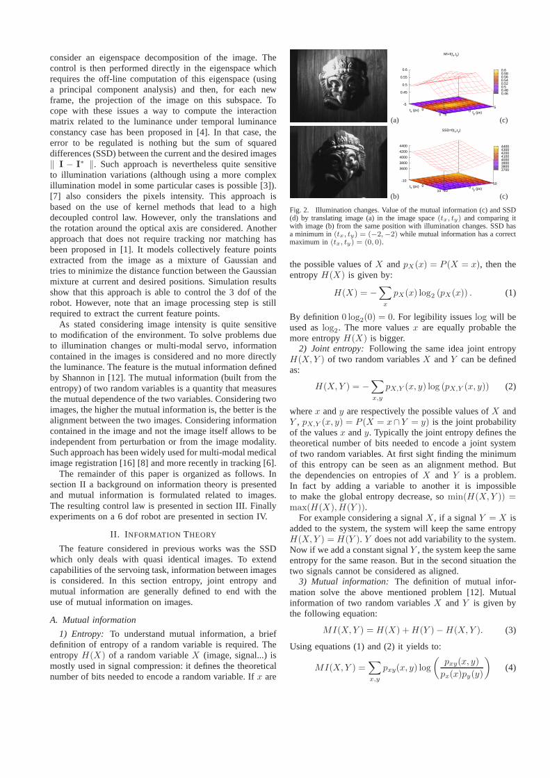
Fig. 4. First experiment: global illumination changes. (a)Mutual infor-mation, (c) translation part of∆r (in meter) and (d) rotational part of∆r
(◦) with x axis in seconds. (b) Final joint histogram, (e) initial image, (f)desired image, (g) initial images difference and (h) final images differenceI∗− I.
whereZ is the depth of the point relative to the camera frameand x and y are the coordinates of the point in the imageframe depending on the camera intrinsic parameters. Giventhe equation ofG, the HessianH is given by:
H =∂G
∂r
= −∑
i,j
∂pij
∂r
⊤ ∂pij
∂r
(
1
pij
−1
pi
)
+∂2pij
∂r2
(
pij
pi
)
≃ −∑
i,j
∂pij
∂r
⊤ ∂pij
∂r
(
1
pij
−1
pi
)
. (20)
The last term of the second equation is quasi null near thedesired position and is very expensive to compute. Since itis usual in visual servoing to compute the interaction matrixat the desired position [2], this term is neglected in thefollowing experiments without affecting the convergence.
IV. EXPERIMENTAL RESULTS
All the experiments reported in this paper have beenobtained using a camera mounted on the end-effector of asix dof gantry robot. Computation time is 22ms for each320 × 240 frames using a 2.6 Ghz PC.

(a) (b)
(c) (d)
Fig. 5. Depth approximation. (a) Initial image, (b) desiredimage, (c) initialimages difference and (d) final images differenceI
∗− I.
A. Visual servoing positioning experiments
A set of experiments shows the behavior of our approachfor positioning task. In each cases, the manipulator is firstmoved to the desired poser∗ and the corresponding pictureI∗ is acquired. The manipulator is then moved to its initial
poser. The control signals computed using equation (16) aresent to the robot controller until convergence. To validatethequality of the results, the transformation∆r betweenr andr∗ is computed and analyzed.
1) General analysis: We will first consider the behavior ofthe algorithm using a planar object so that the object and theimage planes are parallel at the desired pose. The initial errorpose is∆rinit = (15cm,−15cm, 30cm,−6◦,−6◦, 18◦). Theglobal illumination of the entire scene has been modifiedduring the realization of the task. Figure 4 pictures theresults of the first experiment. Here an approximation ofthe depth of the plane at the desired pose is known, theninteraction matrix are computed using a constant depthZ =70cm at each point. Results are quite accurate: Figure 4(c) and (d) show the pose error between the desired andfinal positions during the servoing task. The final pose error∆r is (0.1mm,−0.1mm,−0.1mm, 0.01◦,−0.01◦,−0.01◦).The final images differenceI(rfinal) − I
∗ is not null sincethe global illumination has been modified. However thealignment can be shown in the image representing the jointhistogram between the imagesI(rfinal) and I
∗: along theaxes the luminances of the two images are plotted, fromleft to right for final image and from top to bottom for thedesired image. The feature space is constructed by countingthe number of times a combination of grey values occurs.For each pair of corresponding points(x, y), with x a pointin the imageI at final poserfinal and y a point in thedesired imageI∗, the entry (I(x, rfinal), I∗(y)) in the featurespace is increased. Using this representation (See Figure 4(b)) a quasi linear relation betweenI(rfinal) and I
∗ isvisible, depicting an alignment between the two images witha decreased illumination inI(rfinal).
Let us note that at the beginning of the experiment thebin-size of the histogramh is set toNc = 8, increasingthe domain of convergence, and the parameterµ of theLevenberg-Marquardt method is set toµ = 0.1, favouringa steepest descent approach. Using this set of parameters
(a) (b)
(c) (d)
Fig. 6. Occlusions robustness. (a) Initial image, (b) desired image, (c)initial images difference and (d) final images differenceI
∗− I.
during all the experiment leads to approximate results: thefirst issue encountered is that the current pose reaches avalley of the cost function which the steepest descent doesnot deal with (as in [4]). Consequently an error remains onthe couples of movements(tx, θy) and (ty, θx). The secondproblem is that considering a smallNc yields to a lessprecise minimum. Parametersµ and Nc are then modifiedduring minimization. A polynomial filter is considered todetect the local minimum of the cost function. In such case,parametersµ andNc are smoothly updated, increasingNcand decreasingµ (leading to a Gauss-Newton minimizationprocess).
2) Robustness wrt depth approximation: To supportthe use of a constant depth in the computation ofthe interaction matrix an experiment on non-planarobject has been released. The initial pose error is(8cm,−8cm, 8cm,−4◦,−5◦, 18◦). The behaviour of the po-sitioning task remains almost the same than the previ-ous experiment. Result still shows a low positioning errorof (0.2mm,−0.1mm,−0.1mm, 0.01◦,−0.01◦,−0.01◦) (SeeFigure 5).
3) Robustness wrt occlusion: The next experiment (scenesimilar to the first one) deals with a large partial occlusion.An object (video tape) is added to the scene after the learningstep. Despite the introduction of the object in the scene,the manipulator is still moving toward the desired position,as in previous experiments. Finally the translation error isabout (0.1mm,−0.1mm,−0.1mm) and the rotational errorof (0.01◦,−0.01◦,−0.01◦) showing robustness to occlusionsas expected (See Figure 6).
4) Robustness wrt large illumination changes: The goalof the last positioning experiment illustrates the robustnessto large and non global illumination changes that SSDbased approaches can not deal with. Light configuration iswidely modified during the realization of the task leading tonon-uniform lighting variation. The configuration allows tolight independently various parts of the scene. The differentillumination conditions in the image at the desired andinitial poses is shown in Figure 7: at the desired posethe left part of the scene is illuminated and in the initialpose it is the right part. Then at the alignment position,the right part of the current image is a brighter version of

0.4
0.6
0.8
1
1.2
1.4
1.6
1.8
2
2.2
2.4
0 20 40 60 80 100 120
MI
(a) (b)
-0.15
-0.1
-0.05
0
0.05
0.1
0 20 40 60 80 100 120
txtytz
(c)-14
-12
-10
-8
-6
-4
-2
0
2
4
0 20 40 60 80 100 120
uθxuθyuθz
(d)
(e) (f)
(g) (h)
Fig. 7. Robustness to illumination changes. (a) Mutual information, (c)translation part of∆r (meter) and (d) rotational part of∆r (◦) with x axisin seconds. (b) Final joint histogram, (e) initial image, (f) desired image,(g) initial images difference and (h) final images difference I
∗− I.
the desired image, and the left part of the current imageis a darker version of the desired image. As in the firstexperiment the images difference is not null. However thealignment can be seen in the final joint histogram image:two lines are visible corresponding to two quasi linearrelations. One for each part of the image. Then the useof mutual information that deals with non linear relationbetween the images totally makes sense in such conditionswhile conventional SSD minimization would fail. Finallythe manipulator reaches the desired pose with a final poseerror of (0.4mm,−0.4mm,−0.1mm,−0.05◦, 0.06◦, 0.01◦)that are rather accurate results.
Another experiment has been tested using light changesduring the servoing task. A presentation of these experimentsis given in the video accompanying this paper.
B. Multimodal image-based navigation using image memory
In the introduction of this paper we suggested that theproposed approach is able to consider multi-modal images.To illustrate this property, we will consider an image-basednavigation task that uses image memory. Following [11], weconsider that the navigation task is defined in the sensorspace by a database of images acquired during a learningstep. This defines an image path which provides enoughinformation to control the robotic system. In this system thedesired imageI∗ used in (14) will vary with time. The costfunction to minimize is then
r∗ = min
r(−MI(I(r), I∗(t))) . (21)
0.3
0.31
0.32
0.33
0.34
0.35
0.36
0.37
0.38
0.39
0 2 4 6 8 10 12 14 16 18 20 22
MI
(a) (b)
(c) (d)
(e) (f)
Fig. 8. A multi-modal servoing task. (a) Mutual informationwrt time(seconds), (b) desired image, (c) initial image, (d) initial image overlaid onthe desired image, (e) final image, (f) final image overlaid onthe desiredimage.
The next desired imageI∗(t) is taken in the database whenthe gradient of the mutual information betweenI(r) andI∗(t) is bellow a given threshold.
To illustrate the ability of our approach to consider multi-modal images, the learning step was used on a 1:25000 mapwhile the navigation was used on aerial image. These mapand aerial image have been acquired using theIGN (NationalInstitute of Geography) geoportail (http://www.geoportail.fr)which is a tool similar to google earth. Map and aerial imageshave the same scale.
During the servoing task the aerial images were consid-ered. The current and desired images are then very different(see Figure 8). Considering these extreme conditions, mostof the intensity-based or feature-based matching techniquesbetween current and desired images would fail. Neverthe-less considering mutual-information, experiment shows verygood results. The behavior of the visual servoing consideringmultimodal capabilities is shown on Figure 8. Figure 8ashows the desired image (a map) while Figures 8c and 8eshow initial and final image acquired by the camera. Figures8d and 8f show the desired image overlaid on the current one.On Figure 8f, one can see the registration between desiredand final image has been precisely achieved. Figure 8a showsthe value of the mutual information that increase during theservoing task.
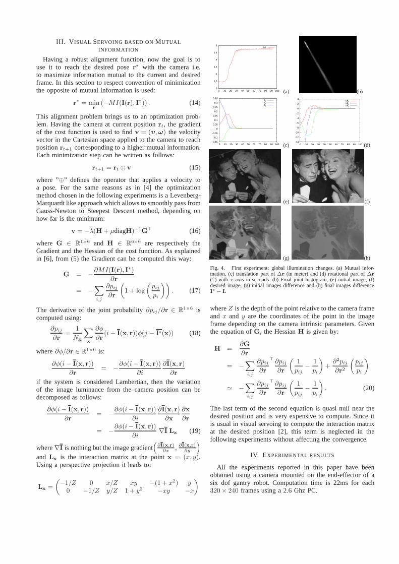
Figure 9 shows five sets of images with the desired imagesextracted from the database and modified over time (top),current image acquired by the camera (middle), and thedesired image overlaid on the current one to show the qualityof the registration, and thus of the trajectory tracking process(bottom). Figure 10 shows both the learnt trajectory and thetrajectory obtained during the realization of the navigationtask. A presentation of these experiments is also availablein
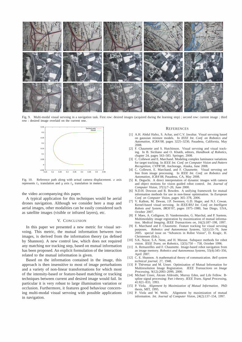
Fig. 9. Multi-modal visual servoing in a navigation task. First row: desired images (acquired during the learning step); second row: current image ; thirdrow : desired image overlaid on the current one.
-0.05
0
0.05
0.1
0.15
0.2
0.25
0.3
0.35
0.15 0.2 0.25 0.3 0.35 0.4 0.45 0.5 0.55
Desired pathResult
Fig. 10. Reference path along with actual camera displacement. x axisrepresentstx translation andy axis ty translation in meters.
the video accompanying this paper.A typical application for this techniques would be aerial
drones navigation. Although we consider here a map andaerial images, other modalities can be easily considered suchas satellite images (visible or infrared layers), etc.
V. CONCLUSION
In this paper we presented a new metric for visual ser-voing. This metric, the mutual information between twoimages, is derived from the information theory (as definedby Shannon). A new control law, which does not requiredany matching nor tracking step, based on mutual informationhas been proposed. An explicit formulation of the interactionrelated to the mutual information is given.
Based on the information contained in the image, thisapproach is then insensitive to most of image perturbationsand a variety of non-linear transformations for which mostof the intensity-based or feature-based matching or trackingtechniques between current and desired image would fail. Inparticular it is very robust to large illumination variation orocclusion. Furthermore, it features good behaviour concern-ing multi-modal visual servoing with possible applicationsin navigation.
REFERENCES
[1] A.H. Abdul Hafez, S. Achar, and C.V. Jawahar. Visual servoing basedon gaussian mixture models. InIEEE Int. Conf. on Robotics andAutomation, ICRA’08, pages 3225–3230, Pasadena, California, May2008.
[2] F. Chaumette and S. Hutchinson. Visual servoing and visual track-ing. In B. Siciliano and O. Khatib, editors,Handbook of Robotics,chapter 24, pages 563–583. Springer, 2008.
[3] C. Collewet and E. Marchand. Modeling complex luminancevariationsfor target tracking. InIEEE Int. Conf. on Computer Vision and PatternRecognition, CVPR’08, Anchorage, Alaska, June 2008.
[4] C. Collewet, E. Marchand, and F. Chaumette. Visual servoing setfree from image processing. InIEEE Int. Conf. on Robotics andAutomation, ICRA’08, Pasadena, CA, May 2008.
[5] K. Deguchi. A direct interpretation of dynamic images with cameraand object motions for vision guided robot control.Int. Journal ofComputer Vision, 37(1):7–20, June 2000.
[6] N.D.H. Dowson and R. Bowden. A unifying framework for mutualinformation methods for use in non-linear optimisation. InEuropeanConf. on Computer Vision, pages 365–378, 2006.
[7] V. Kallem, M. Dewan, J.P. Swensen, G.D. Hager, and N.J. Cowan.Kernel-based visual servoing. InIEEE/RSJ Int. Conf. on IntelligentRobots and System, IROS’07, pages 1975–1980, San Diego, USA,October 2007.
[8] F. Maes, A. Collignon, D. Vandermeulen, G. Marchal, and P. Suetens.Multimodality image registration by maximization of mutual informa-tion. Medical Imaging, IEEE Transactions on, 16(2):187–198, 1997.
[9] E. Marchand and F. Chaumette. Feature tracking for visual servoingpurposes. Robotics and Autonomous Systems, 52(1):53–70, June2005. special issue on “Advances in Robot Vision”, D. Kragic, H.Christensen (Eds.).
[10] S.K. Nayar, S.A. Nene, and H. Murase. Subspace methods for robotvision. IEEE Trans. on Robotics, 12(5):750 – 758, October 1996.
[11] A. Remazeilles and F. Chaumette. Image-based robot navigation froman image memory.Robotics and Autonomous Systems, 55(4):345–356,April 2007.
[12] C. E. Shannon. A mathematical theory of communication.Bell systemtechnical journal, 27, 1948.
[13] P. Thevenaz and M. Unser. Optimization of Mutual Information forMultiresolution Image Registration. IEEE Transactions on ImageProcessing, 9(12):2083–2099, 2000.
[14] Michael Unser, Akram Aldroubi, Murray Eden, and Life Fellow. B-spline signal processing: Part i-theory.IEEE Trans. Signal Processing,41:821–833, 1993.
[15] P. Viola. Alignment by Maximization of Mutual Information. PhDthesis, MIT, 1995.
[16] P. Viola and W. Wells. Alignment by maximization of mutualinformation. Int. Journal of Computer Vision, 24(2):137–154, 1997.


![Uncalibrated 3D Stereo Image-based Dynamic Visual Servoing ... · uncalibrated visual servoing with robot dynamics has been tackled with new adaptive controllers [11],[26]. However,](https://img.pdfslide.us/doc/110x75/606d9bc0175fff2c42161cce/uncalibrated-3d-stereo-image-based-dynamic-visual-servoing-uncalibrated-visual.jpg)


![Visual Servoing-based Navigation for Monitoring Row-Crop ... · Traditionally, visual servoing techniques [11] are used for controlling robotic arms and manipulators. These techniques](https://img.pdfslide.us/doc/110x75/606d9bc1175fff2c42161cd5/visual-servoing-based-navigation-for-monitoring-row-crop-traditionally-visual.jpg)