Embed Size (px)
DESCRIPTION
Entity Relationship Model
Citation preview
Entity-Relationship Model
IF6112 – Entity Relationship Diagram03-09-2006
EntityEntity--Relationship ModelRelationship ModelDesign ProcessModelingConstraintsE-R Diagram Design Issues Weak Entity Sets Extended E-R FeaturesDesign of the Bank DatabaseReduction to Relation SchemasDatabase DesignUML
IF6112 – Entity Relationship Diagram03-09-2006
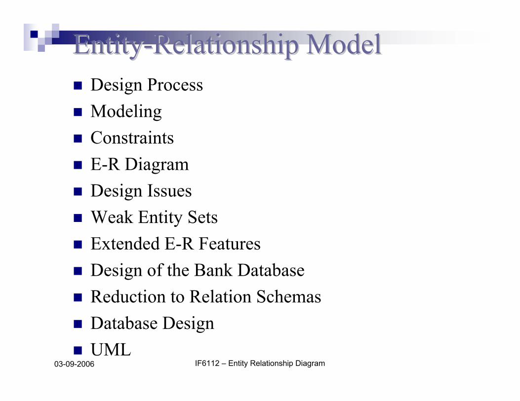
ModelingModelingA database can be modeled as:
a collection of entities,relationship among entities.
An entity is an object that exists and is distinguishable from other objects.
Example: specific person, company, event, plantEntities have attributes
Example: people have names and addresses
An entity set is a set of entities of the same type that share the same properties.
Example: set of all persons, companies, trees, holidays
IF6112 – Entity Relationship Diagram03-09-2006
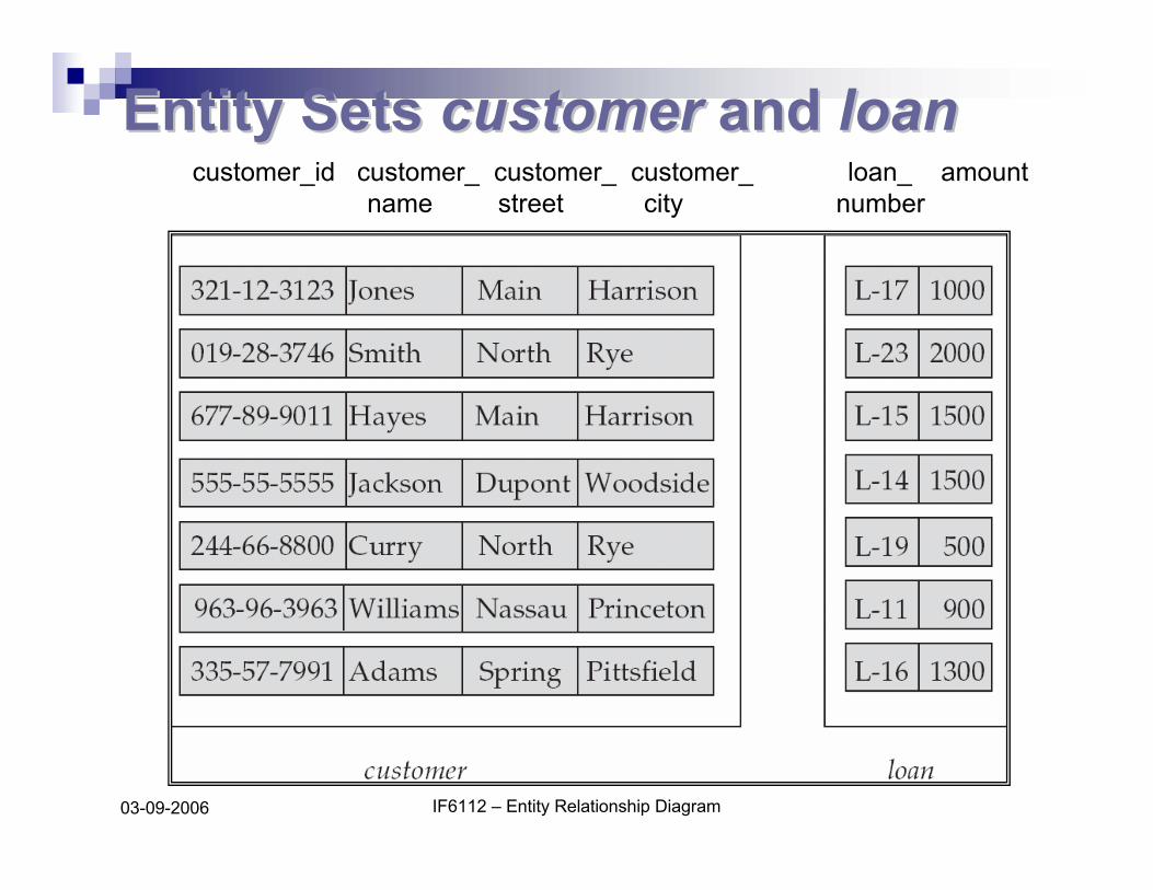
Entity Sets Entity Sets customercustomer and and loanloancustomer_id customer_ customer_ customer_ loan_ amount
name street city number

IF6112 – Entity Relationship Diagram03-09-2006
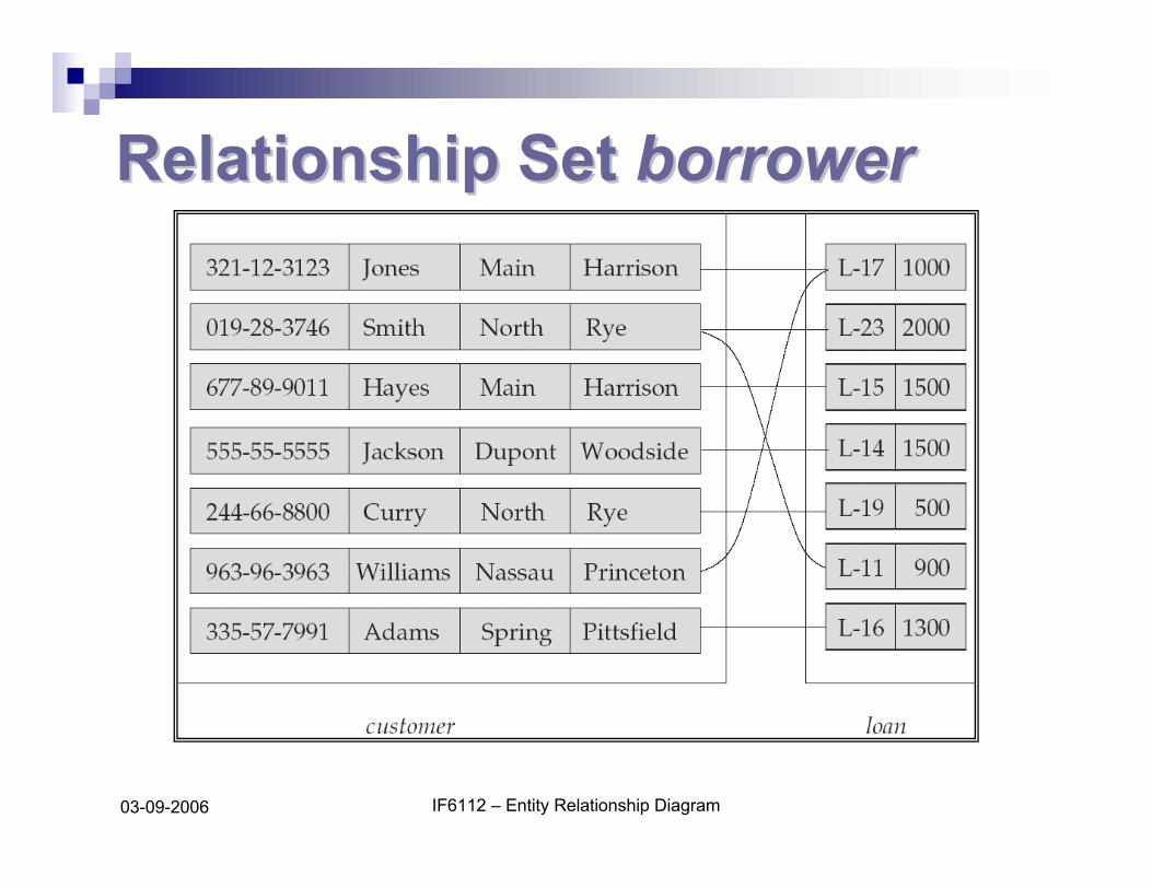
Relationship SetsRelationship SetsA relationship is an association among several entitiesExample:
Hayes depositor A-102customer entity relationship set account entity
A relationship set is a mathematical relation among n ≥ 2 entities, each taken from entity sets
{(e1, e2, … en) | e1 ∈ E1, e2 ∈ E2, …, en ∈ En}
where (e1, e2, …, en) is a relationshipExample:
(Hayes, A-102) ∈ depositor
IF6112 – Entity Relationship Diagram03-09-2006
Relationship Set Relationship Set borrowerborrower
IF6112 – Entity Relationship Diagram03-09-2006
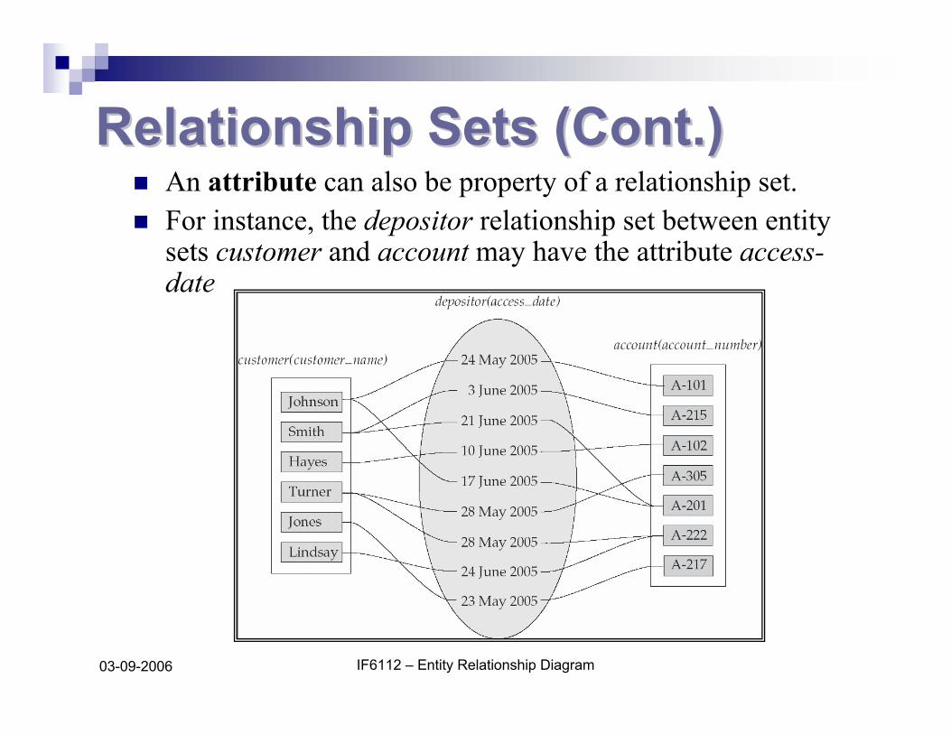
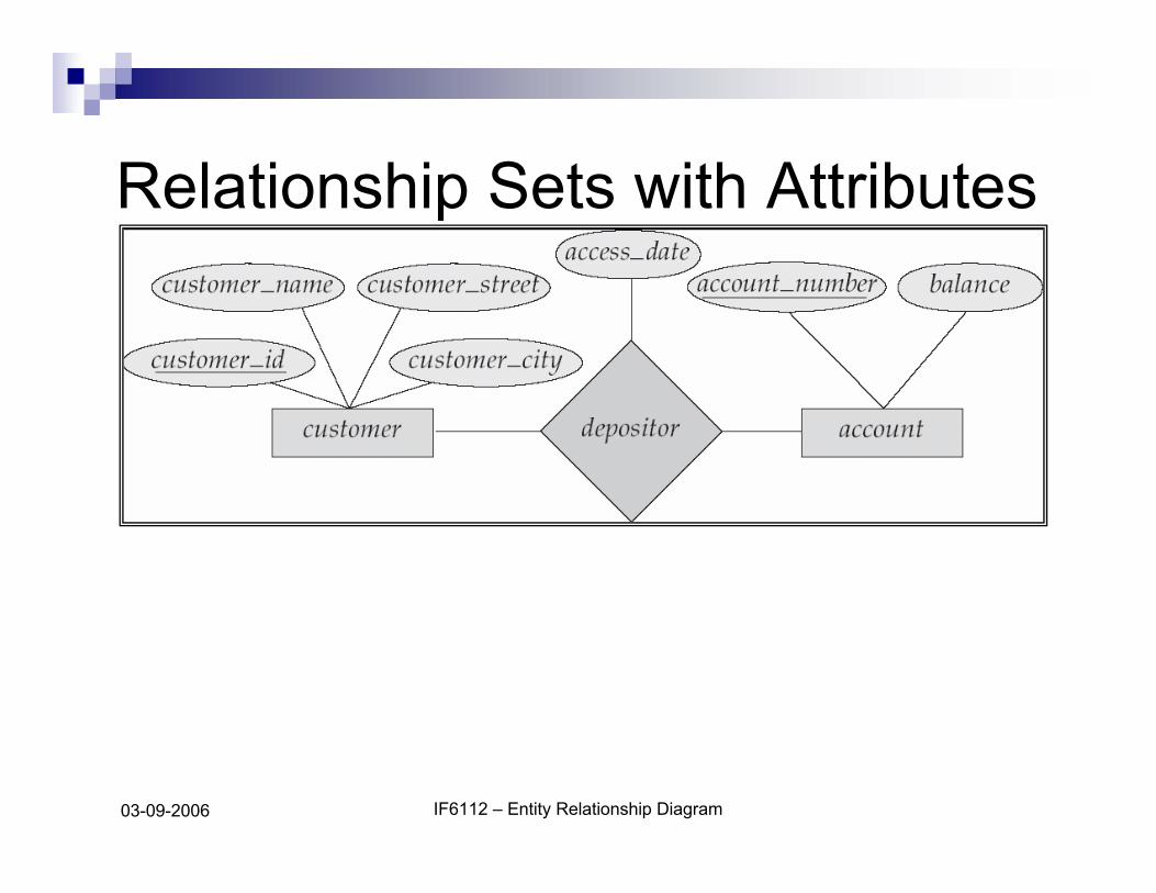
Relationship Sets (Cont.)Relationship Sets (Cont.)An attribute can also be property of a relationship set.For instance, the depositor relationship set between entity sets customer and account may have the attribute access-date
IF6112 – Entity Relationship Diagram03-09-2006
Degree of a Relationship SetDegree of a Relationship SetRefers to number of entity sets that participate in a relationship set.Relationship sets that involve two entity sets are binary (or degree two). Generally, most relationship sets in a database system are binary.Relationship sets may involve more than two entity sets.
Relationships between more than two entity sets are rare. Most relationships are binary. (More on this later.)
Example: Suppose employees of a bank may have jobs (responsibilities) at multiple branches, with different jobs at different branches. Then there is a ternary relationship set between entity sets employee, job, and branch
IF6112 – Entity Relationship Diagram03-09-2006
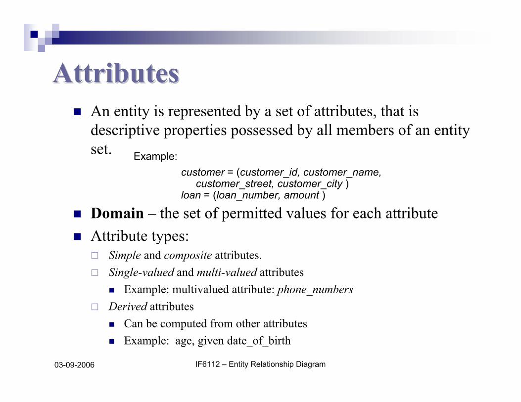
AttributesAttributesAn entity is represented by a set of attributes, that is descriptive properties possessed by all members of an entity set.
Domain – the set of permitted values for each attribute Attribute types:
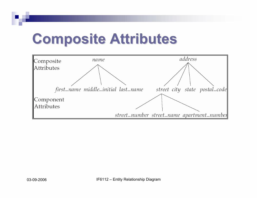
Simple and composite attributes.Single-valued and multi-valued attributes
Example: multivalued attribute: phone_numbersDerived attributes
Can be computed from other attributesExample: age, given date_of_birth
Example: customer = (customer_id, customer_name,
customer_street, customer_city )loan = (loan_number, amount )
IF6112 – Entity Relationship Diagram03-09-2006
Composite AttributesComposite Attributes
IF6112 – Entity Relationship Diagram03-09-2006
Mapping Cardinality ConstraintsMapping Cardinality Constraints
Express the number of entities to which another entity can be associated via a relationship set.Most useful in describing binary relationship sets.For a binary relationship set the mapping cardinality must be one of the following types:
One to oneOne to manyMany to oneMany to many
IF6112 – Entity Relationship Diagram03-09-2006
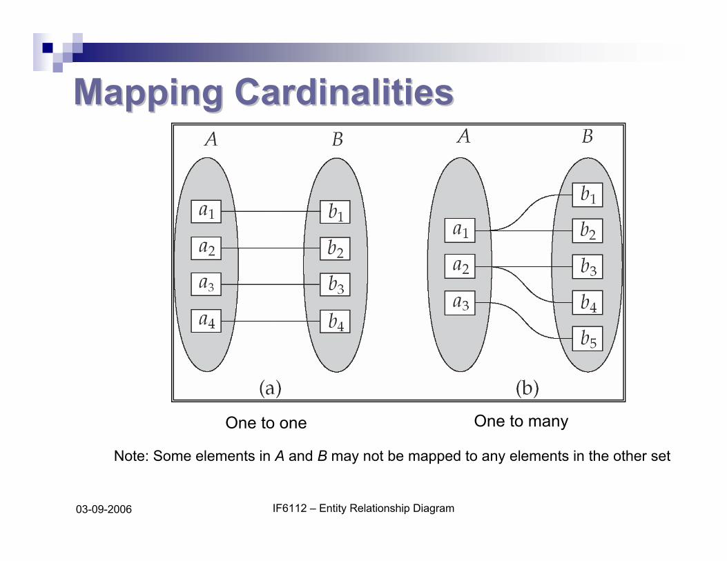
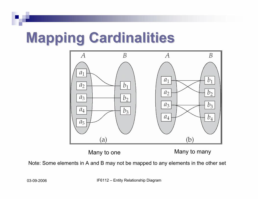
Mapping CardinalitiesMapping Cardinalities
One to one One to many
Note: Some elements in A and B may not be mapped to any elements in the other set
IF6112 – Entity Relationship Diagram03-09-2006
Mapping CardinalitiesMapping Cardinalities
Many to one Many to many
Note: Some elements in A and B may not be mapped to any elements in the other set
IF6112 – Entity Relationship Diagram03-09-2006
KeysKeysA super key of an entity set is a set of one or more attributes whose values uniquely determine each entity.A candidate key of an entity set is a minimal super key
Customer_id is candidate key of customeraccount_number is candidate key of account
Although several candidate keys may exist, one of the candidate keys is selected to be the primary key.
IF6112 – Entity Relationship Diagram03-09-2006
Keys for Relationship SetsKeys for Relationship SetsThe combination of primary keys of the participating entity sets forms a super key of a relationship set.
(customer_id, account_number) is the super key of depositorNOTE: this means a pair of entity sets can have at most one relationship in a particular relationship set.
Example: if we wish to track all access_dates to each account by each customer, we cannot assume a relationship for each access. We can use a multivalued attribute though
Must consider the mapping cardinality of the relationship set when deciding the what are the candidate keys Need to consider semantics of relationship set in selecting the primary key in case of more than one candidate key
IF6112 – Entity Relationship Diagram03-09-2006
EE--R DiagramsR Diagrams
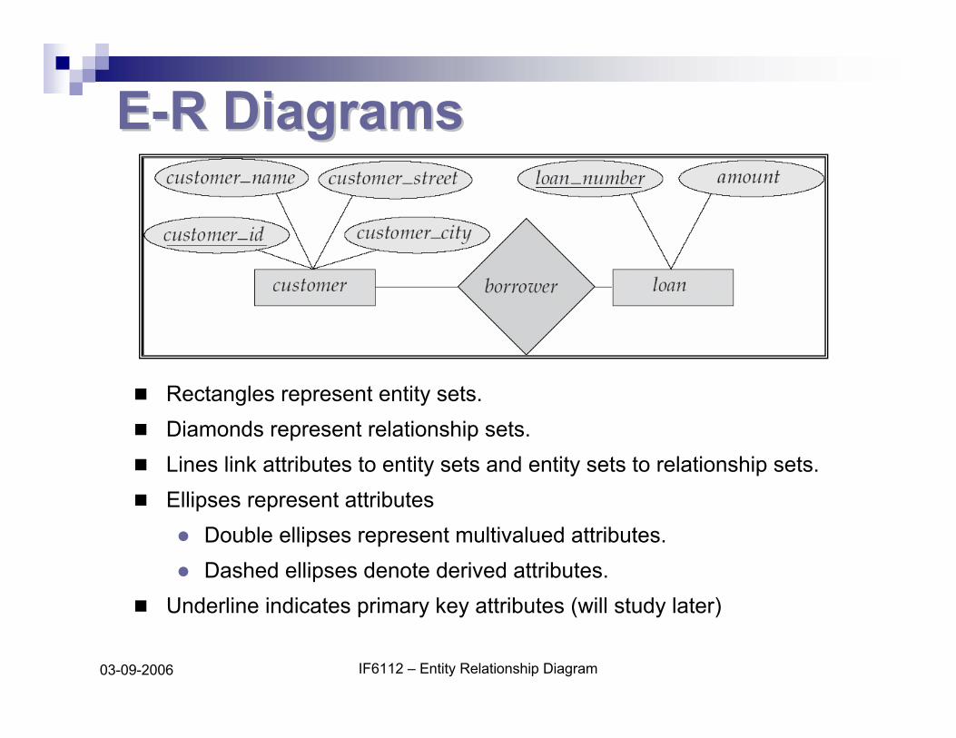
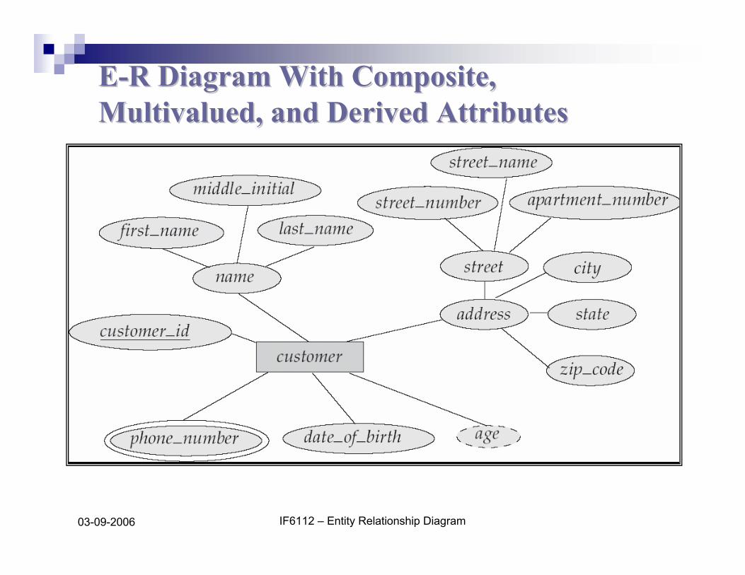
Rectangles represent entity sets.Diamonds represent relationship sets.Lines link attributes to entity sets and entity sets to relationship sets.Ellipses represent attributes
Double ellipses represent multivalued attributes.Dashed ellipses denote derived attributes.
Underline indicates primary key attributes (will study later)
IF6112 – Entity Relationship Diagram03-09-2006
EE--R Diagram With Composite, R Diagram With Composite, Multivalued, and Derived AttributesMultivalued, and Derived Attributes
IF6112 – Entity Relationship Diagram03-09-2006
Relationship Sets with Attributes
IF6112 – Entity Relationship Diagram03-09-2006
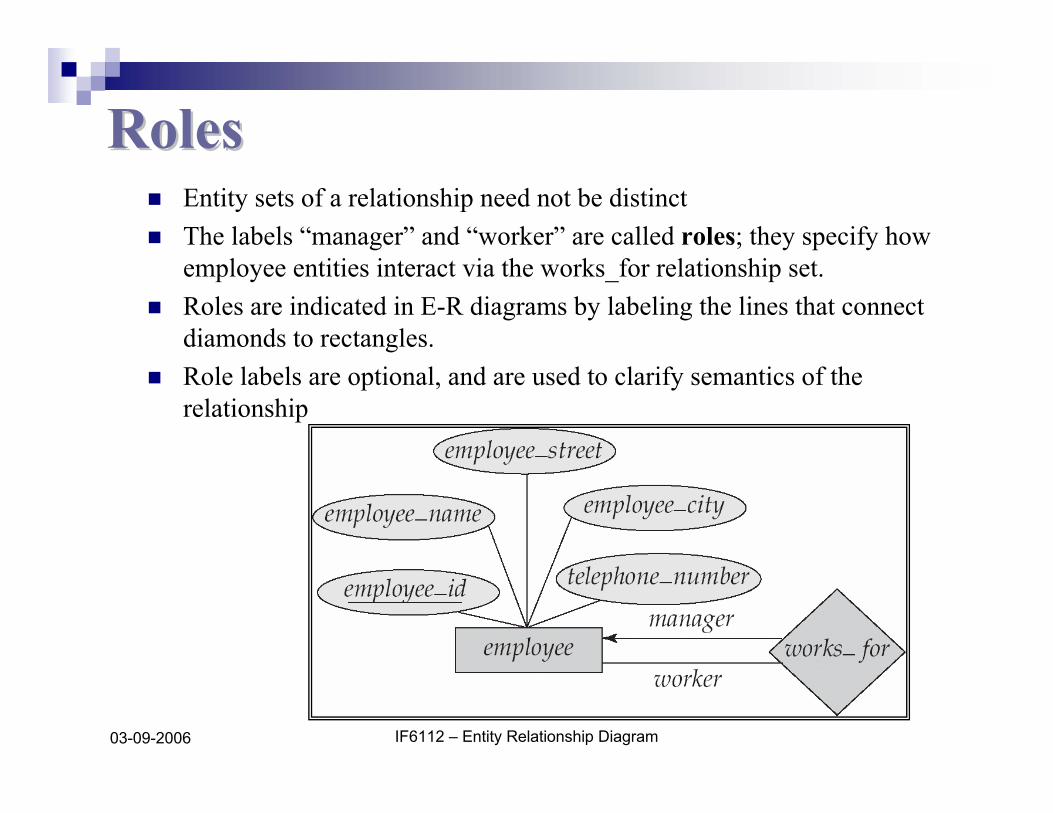
RolesRolesEntity sets of a relationship need not be distinctThe labels “manager” and “worker” are called roles; they specify how employee entities interact via the works_for relationship set.Roles are indicated in E-R diagrams by labeling the lines that connect diamonds to rectangles.Role labels are optional, and are used to clarify semantics of the relationship
IF6112 – Entity Relationship Diagram03-09-2006
Cardinality ConstraintsCardinality Constraints
We express cardinality constraints by drawing either a directed line (→), signifying “one,” or an undirected line (—), signifying “many,” between the relationship set and the entity set.One-to-one relationship:
A customer is associated with at most one loan via the relationship borrowerA loan is associated with at most one customer via borrower
IF6112 – Entity Relationship Diagram03-09-2006
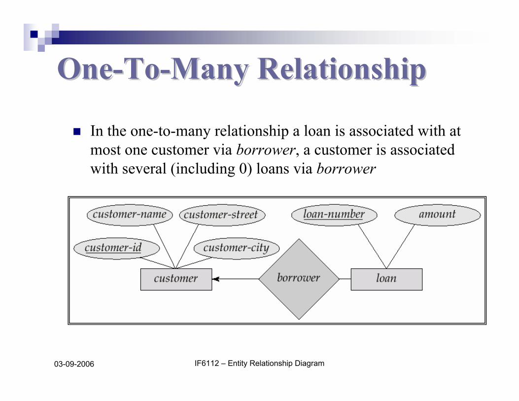
OneOne--ToTo--Many RelationshipMany Relationship
In the one-to-many relationship a loan is associated with at most one customer via borrower, a customer is associated with several (including 0) loans via borrower
IF6112 – Entity Relationship Diagram03-09-2006
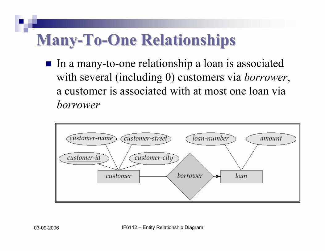
ManyMany--ToTo--One RelationshipsOne RelationshipsIn a many-to-one relationship a loan is associated with several (including 0) customers via borrower, a customer is associated with at most one loan via borrower
IF6112 – Entity Relationship Diagram03-09-2006
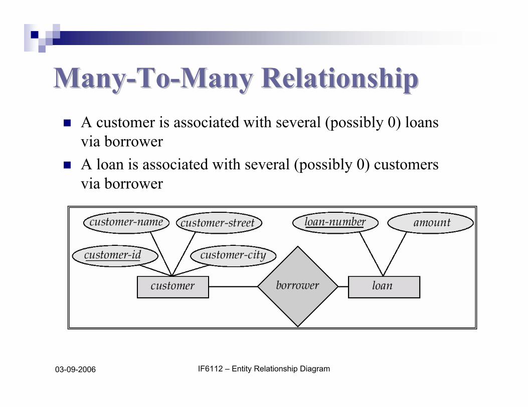
ManyMany--ToTo--Many RelationshipMany RelationshipA customer is associated with several (possibly 0) loans via borrowerA loan is associated with several (possibly 0) customers via borrower
IF6112 – Entity Relationship Diagram03-09-2006
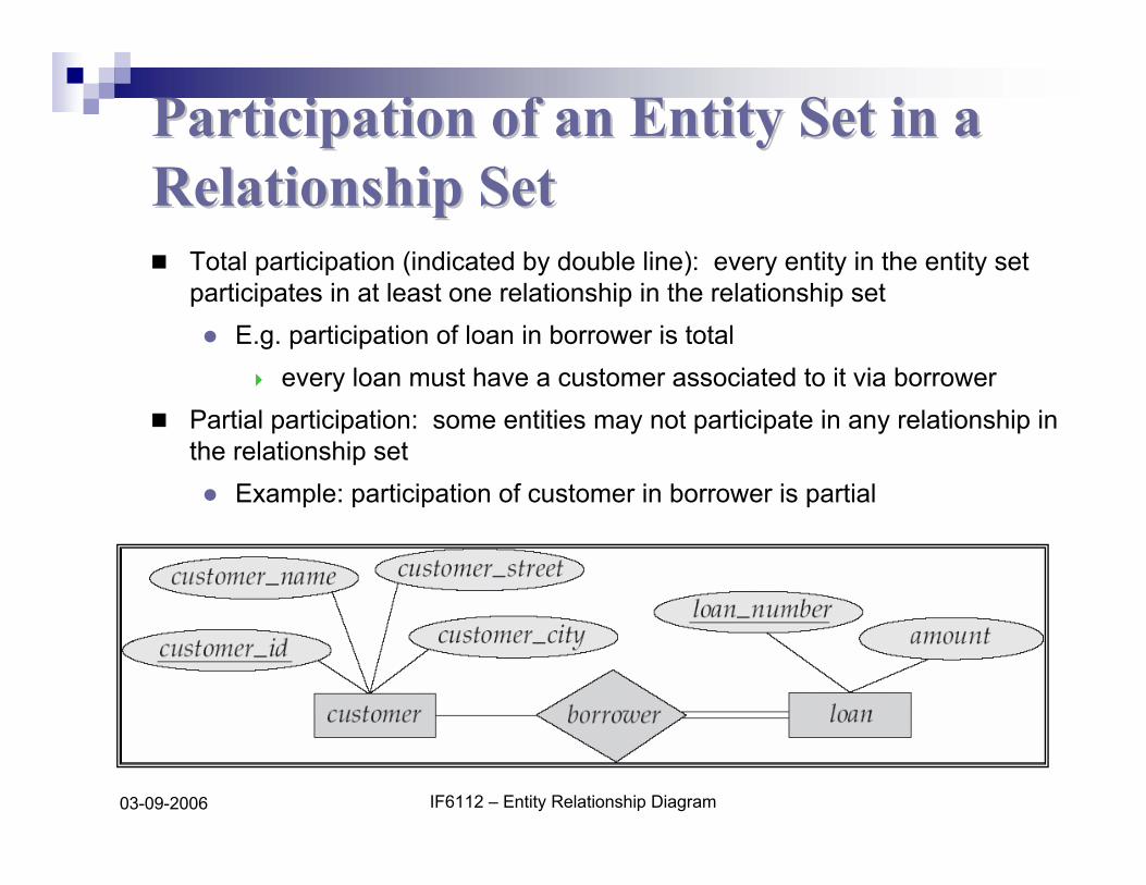
Participation of an Entity Set in a Participation of an Entity Set in a Relationship SetRelationship Set
Total participation (indicated by double line): every entity in the entity set participates in at least one relationship in the relationship set
E.g. participation of loan in borrower is totalevery loan must have a customer associated to it via borrower
Partial participation: some entities may not participate in any relationship in the relationship set
Example: participation of customer in borrower is partial
IF6112 – Entity Relationship Diagram03-09-2006
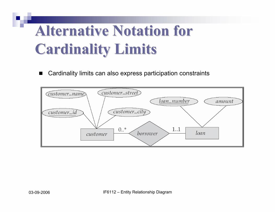
Alternative Notation for Alternative Notation for Cardinality LimitsCardinality Limits
Cardinality limits can also express participation constraints

IF6112 – Entity Relationship Diagram03-09-2006
EE--RR Diagram with a Ternary Diagram with a Ternary RelationshipRelationship

IF6112 – Entity Relationship Diagram03-09-2006
Cardinality Constraints on Cardinality Constraints on Ternary RelationshipTernary Relationship
We allow at most one arrow out of a ternary (or greater degree) relationship to indicate a cardinality constraintE.g. an arrow from works_on to job indicates each employee works on at most one job at any branch.If there is more than one arrow, there are two ways of defining the meaning.
E.g a ternary relationship R between A, B and C with arrows to B and C could mean1. each A entity is associated with a unique entity from B and C or 2. each pair of entities from (A, B) is associated with a unique C entity,
and each pair (A, C) is associated with a unique BEach alternative has been used in different formalismsTo avoid confusion we outlaw more than one arrow
IF6112 – Entity Relationship Diagram03-09-2006
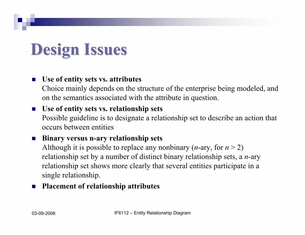
Design IssuesDesign IssuesUse of entity sets vs. attributesChoice mainly depends on the structure of the enterprise being modeled, and on the semantics associated with the attribute in question.Use of entity sets vs. relationship setsPossible guideline is to designate a relationship set to describe an action that occurs between entitiesBinary versus n-ary relationship setsAlthough it is possible to replace any nonbinary (n-ary, for n > 2) relationship set by a number of distinct binary relationship sets, a n-ary relationship set shows more clearly that several entities participate in a single relationship.Placement of relationship attributes
IF6112 – Entity Relationship Diagram03-09-2006
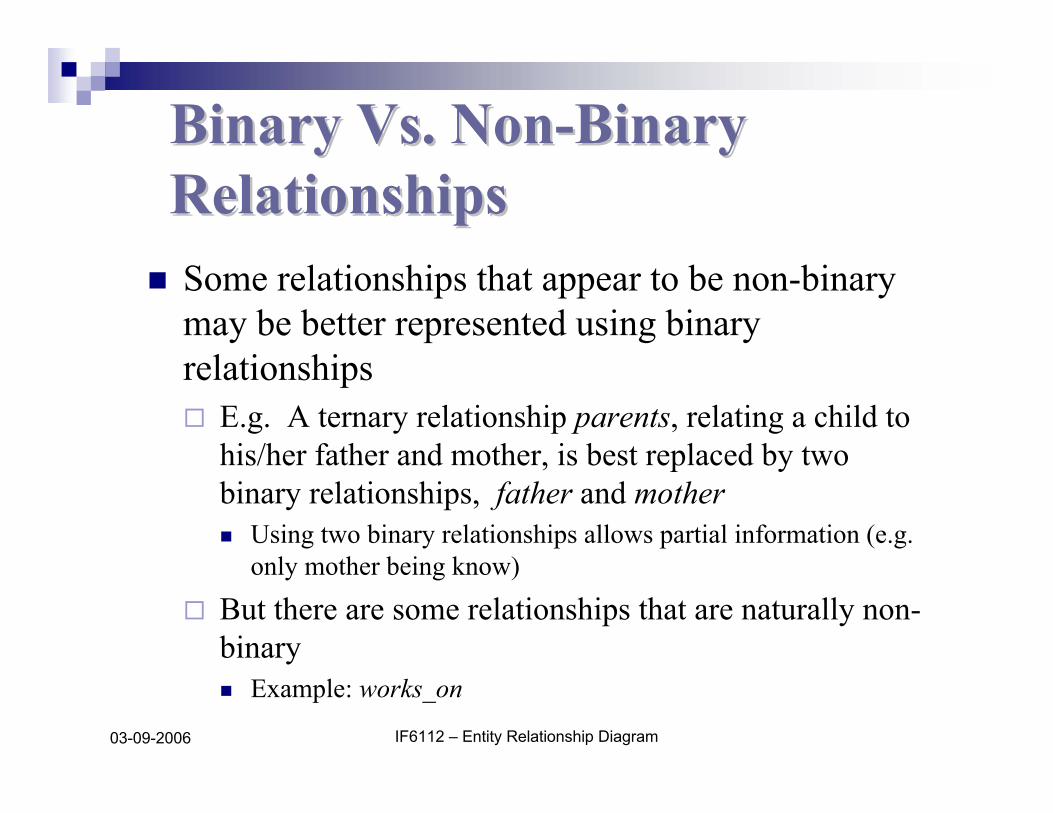
Binary Vs. NonBinary Vs. Non--Binary Binary RelationshipsRelationshipsSome relationships that appear to be non-binary may be better represented using binary relationships
E.g. A ternary relationship parents, relating a child to his/her father and mother, is best replaced by two binary relationships, father and mother
Using two binary relationships allows partial information (e.g. only mother being know)
But there are some relationships that are naturally non-binary
Example: works_on
IF6112 – Entity Relationship Diagram03-09-2006
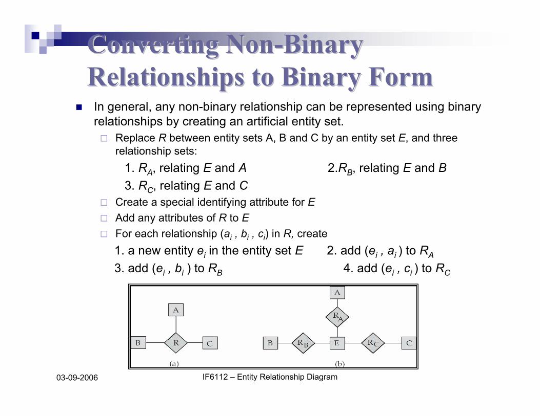
Converting NonConverting Non--Binary Binary Relationships to Binary FormRelationships to Binary FormIn general, any non-binary relationship can be represented using binary relationships by creating an artificial entity set.
Replace R between entity sets A, B and C by an entity set E, and three relationship sets:
1. RA, relating E and A 2.RB, relating E and B3. RC, relating E and C
Create a special identifying attribute for EAdd any attributes of R to E For each relationship (ai , bi , ci) in R, create 1. a new entity ei in the entity set E 2. add (ei , ai ) to RA
3. add (ei , bi ) to RB 4. add (ei , ci ) to RC
IF6112 – Entity Relationship Diagram03-09-2006
Converting NonConverting Non--Binary Relationships Binary Relationships (Cont.)
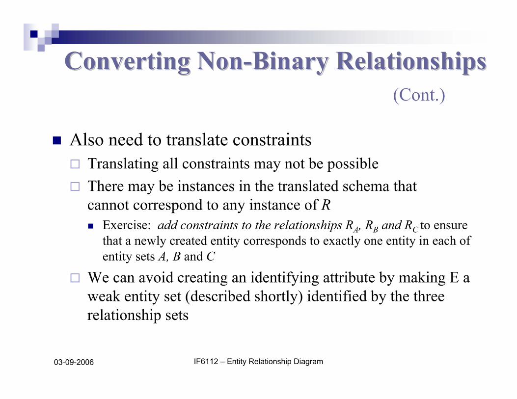
Also need to translate constraintsTranslating all constraints may not be possibleThere may be instances in the translated schema thatcannot correspond to any instance of R
Exercise: add constraints to the relationships RA, RB and RC to ensure that a newly created entity corresponds to exactly one entity in each of entity sets A, B and C
We can avoid creating an identifying attribute by making E a weak entity set (described shortly) identified by the three relationship sets
IF6112 – Entity Relationship Diagram03-09-2006
Mapping Cardinalities affect ER Mapping Cardinalities affect ER DesignDesign
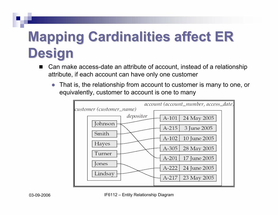
Can make access-date an attribute of account, instead of a relationship attribute, if each account can have only one customer
That is, the relationship from account to customer is many to one, or equivalently, customer to account is one to many


![[PPT]Entity – Relationship Model (E-R Model)sivasnscedbms.weebly.com/.../entity__relationship_model.ppt · Web viewEntity – Relationship Model (E-R Model) Entity – Relationship](https://img.pdfslide.us/doc/110x75/5b04acac7f8b9a2d518df0c5/pptentity-relationship-model-e-r-model-viewentity-relationship-model.jpg)