Embed Size (px)
DESCRIPTION
Entity-Relationship Model. CST203-2 Database Management Systems Lecture 3. Describes data as entities, relationships and attributes. Database Design Process. Requirements collection process Data and functional requirements Conceptual design - PowerPoint PPT Presentation
Citation preview
Entity-Relationship ModelCST203-2 Database Management Systems
Lecture 3
Describes data as entities, relationships and attributes
Database Design ProcessRequirements collection process
Data and functional requirements
Conceptual design Descriptions on entity types, relationships and constraints
Choose a DBMS
Data model mapping
Physical database design
Database system implementation
Entity Sets A database can be modeled as:
a collection of entities, relationship among entities.
An entity is an object that exists and is distinguishable from other objects.
Example: specific person, company, event, plant
Entities have attributes Example: people have names and addresses
An entity type is a collection of entries that have the same attributes
An entity set is a collection of entities of a particular entity type in the database at any point in time
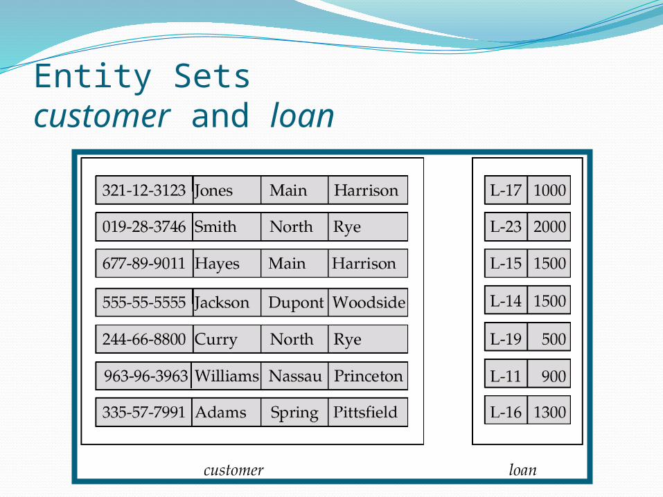
Entity Sets customer and loan
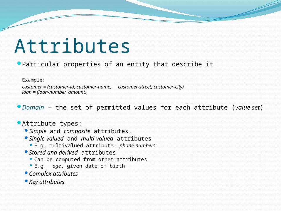
AttributesParticular properties of an entity that describe it
Example: customer = (customer-id, customer-name,customer-street, customer-city)loan = (loan-number, amount)
Domain – the set of permitted values for each attribute (value set)
Attribute types: Simple and composite attributes. Single-valued and multi-valued attributes
E.g. multivalued attribute: phone-numbers Stored and derived attributes
Can be computed from other attributes E.g. age, given date of birth
Complex attributes Key attributes
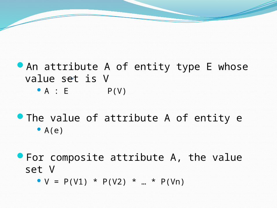
An attribute A of entity type E whose value set is V
A : E P(V)
The value of attribute A of entity e A(e)
For composite attribute A, the value set V V = P(V1) * P(V2) * … * P(Vn)

Composite Attributes
Uniqueness constraintKey attributes
Composite key attributes Composite key must be minimal
Prohibits any two entities from having the same value for the key attribute at the same time
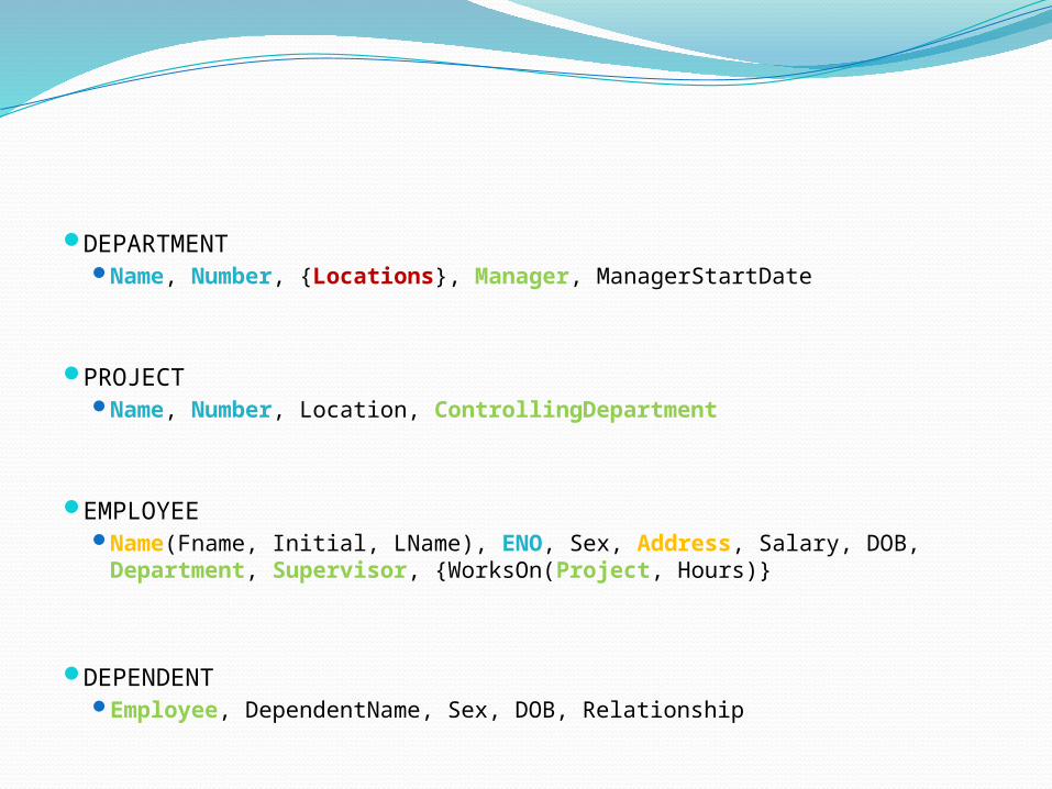
DEPARTMENT Name, Number, {Locations}, Manager, ManagerStartDate
PROJECT Name, Number, Location, ControllingDepartment
EMPLOYEE Name(Fname, Initial, LName), ENO, Sex, Address, Salary, DOB,
Department, Supervisor, {WorksOn(Project, Hours)}
DEPENDENT Employee, DependentName, Sex, DOB, Relationship
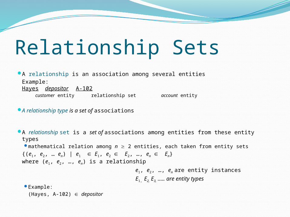
Relationship Sets A relationship is an association among several entities
Example:Hayes depositor A-102
customer entity relationship set account entity
A relationship type is a set of associations
A relationship set is a set of associations among entities from these entity types mathematical relation among n 2 entities, each taken from entity sets
{(e1, e2, … en) | e1 E1, e2 E2, …, en En}where (e1, e2, …, en) is a relationship
e1, e2, …, en are entity instances
E1, E2, E3, ….. are entity types Example:
(Hayes, A-102) depositor
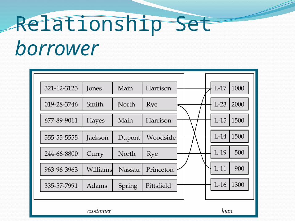
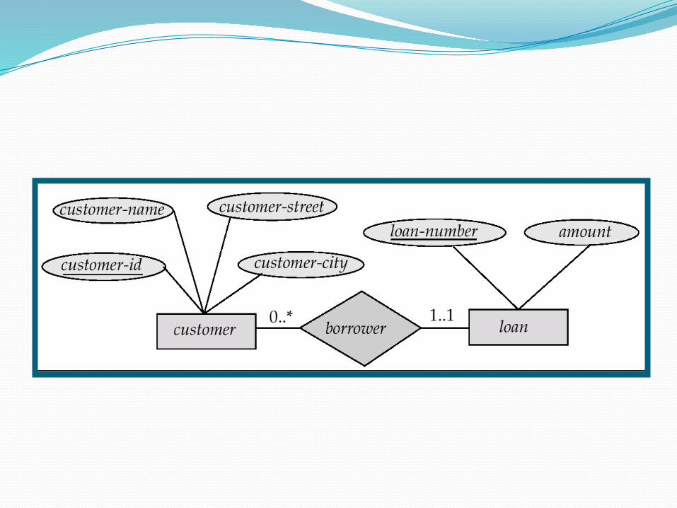
Relationship Set borrower
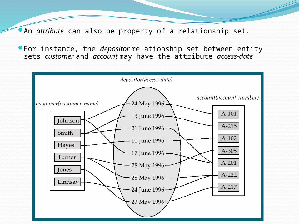
An attribute can also be property of a relationship set.
For instance, the depositor relationship set between entity sets customer and account may have the attribute access-date
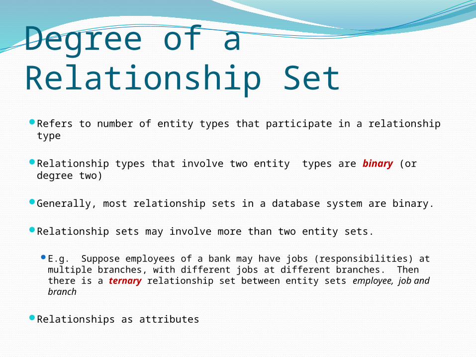
Degree of a Relationship Set Refers to number of entity types that participate in a relationship type
Relationship types that involve two entity types are binary (or degree two)
Generally, most relationship sets in a database system are binary.
Relationship sets may involve more than two entity sets.
E.g. Suppose employees of a bank may have jobs (responsibilities) at multiple branches, with different jobs at different branches. Then there is a ternary relationship set between entity sets employee, job and branch
Relationships as attributes
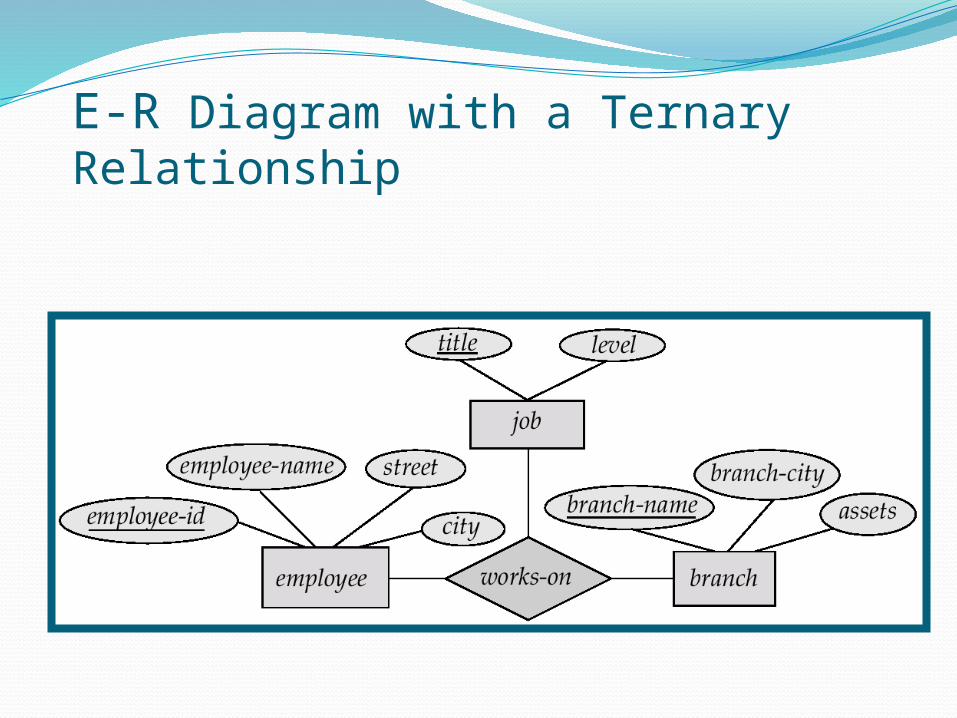
E-R Diagram with a Ternary Relationship
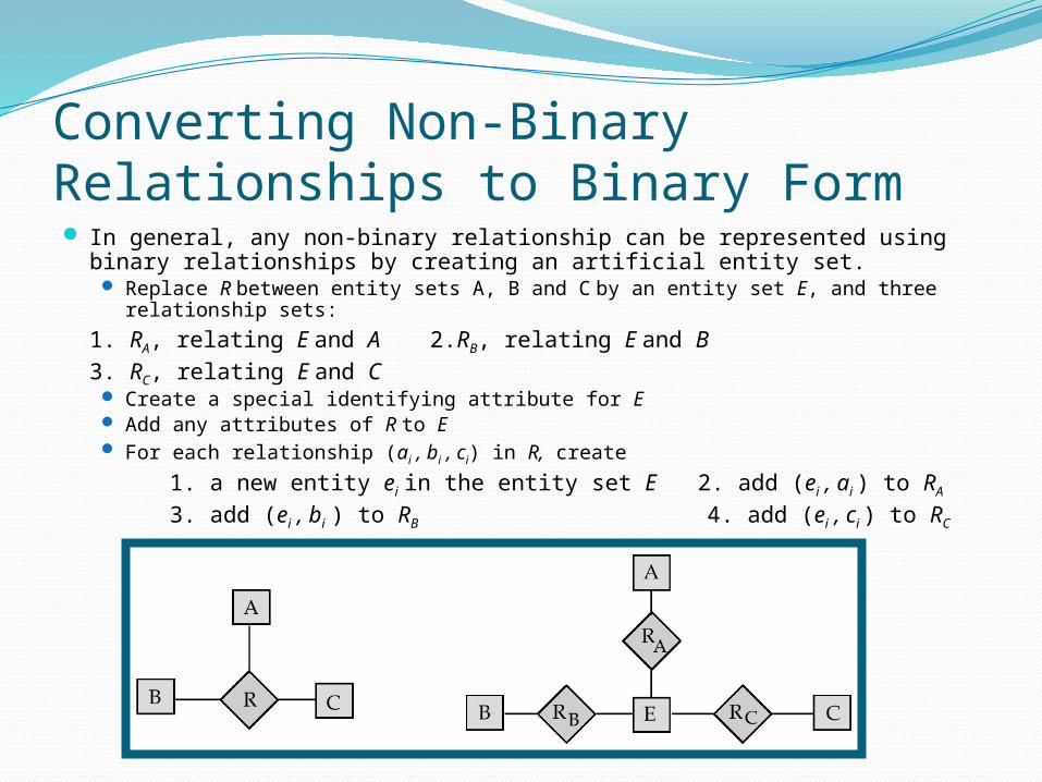
Converting Non-Binary Relationships to Binary Form In general, any non-binary relationship can be represented using binary
relationships by creating an artificial entity set. Replace R between entity sets A, B and C by an entity set E, and three
relationship sets:
1. RA, relating E and A 2.RB, relating E and B3. RC, relating E and C
Create a special identifying attribute for E Add any attributes of R to E For each relationship (ai , bi , ci) in R, create
1. a new entity ei in the entity set E 2. add (ei , ai ) to RA
3. add (ei , bi ) to RB 4. add (ei , ci ) to RC
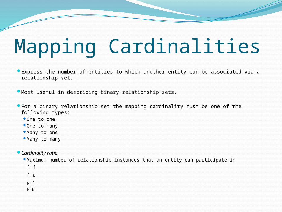
Mapping Cardinalities Express the number of entities to which another entity can be associated via a
relationship set.
Most useful in describing binary relationship sets.
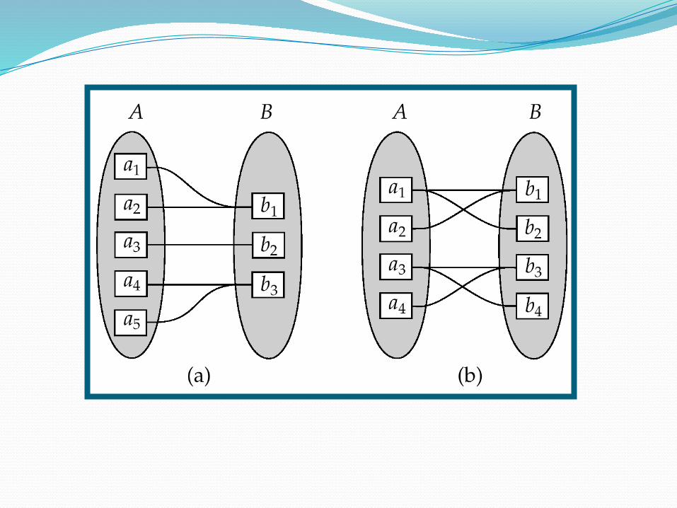
For a binary relationship set the mapping cardinality must be one of the following types: One to one One to many Many to one Many to many
Cardinality ratio Maximum number of relationship instances that an entity can participate in
1:11:N
N:1N:N
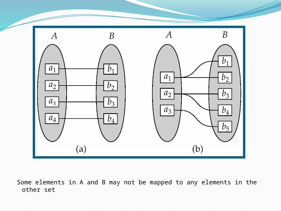
Some elements in A and B may not be mapped to any elements in the other set
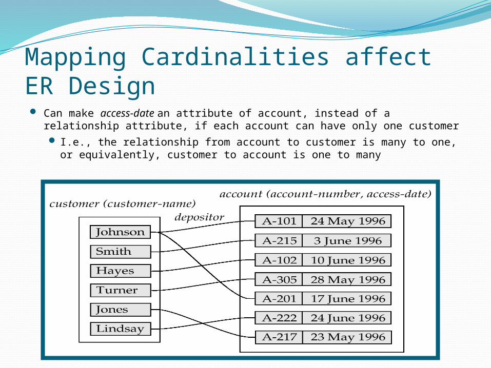
Mapping Cardinalities affect ER Design Can make access-date an attribute of account, instead of a relationship
attribute, if each account can have only one customer I.e., the relationship from account to customer is many to one, or
equivalently, customer to account is one to many
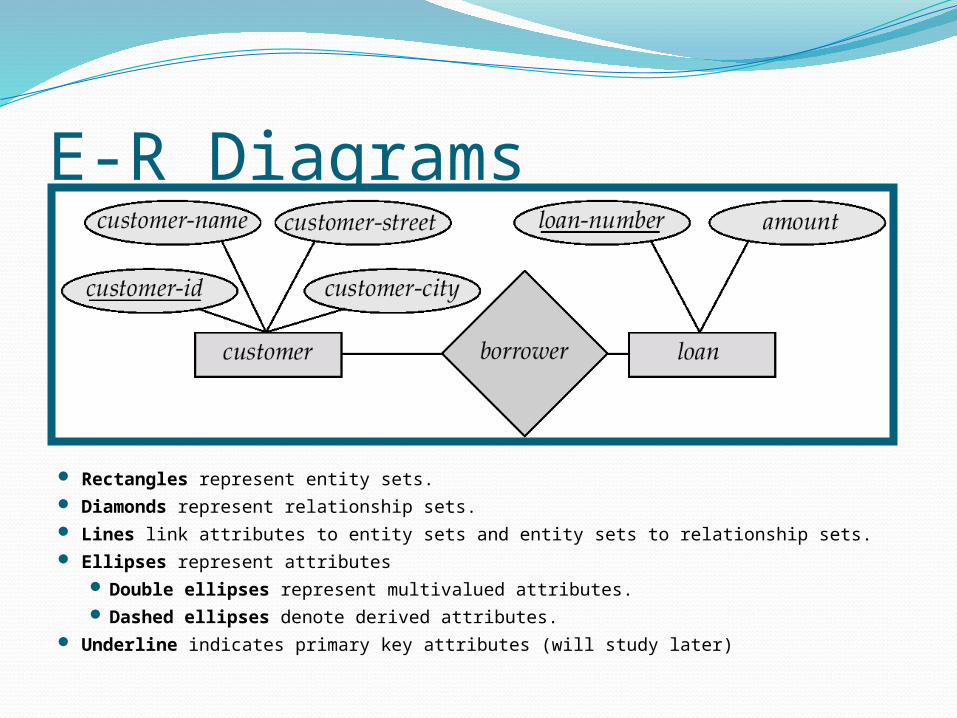
E-R Diagrams
Rectangles represent entity sets. Diamonds represent relationship sets. Lines link attributes to entity sets and entity sets to relationship sets. Ellipses represent attributes
Double ellipses represent multivalued attributes. Dashed ellipses denote derived attributes.
Underline indicates primary key attributes (will study later)
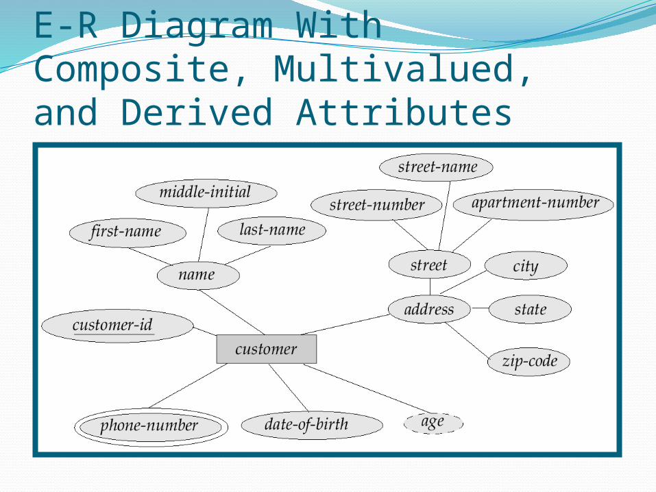
E-R Diagram With Composite, Multivalued, and Derived Attributes
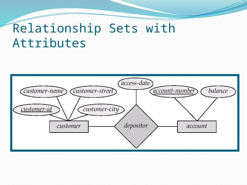
Relationship Sets with Attributes
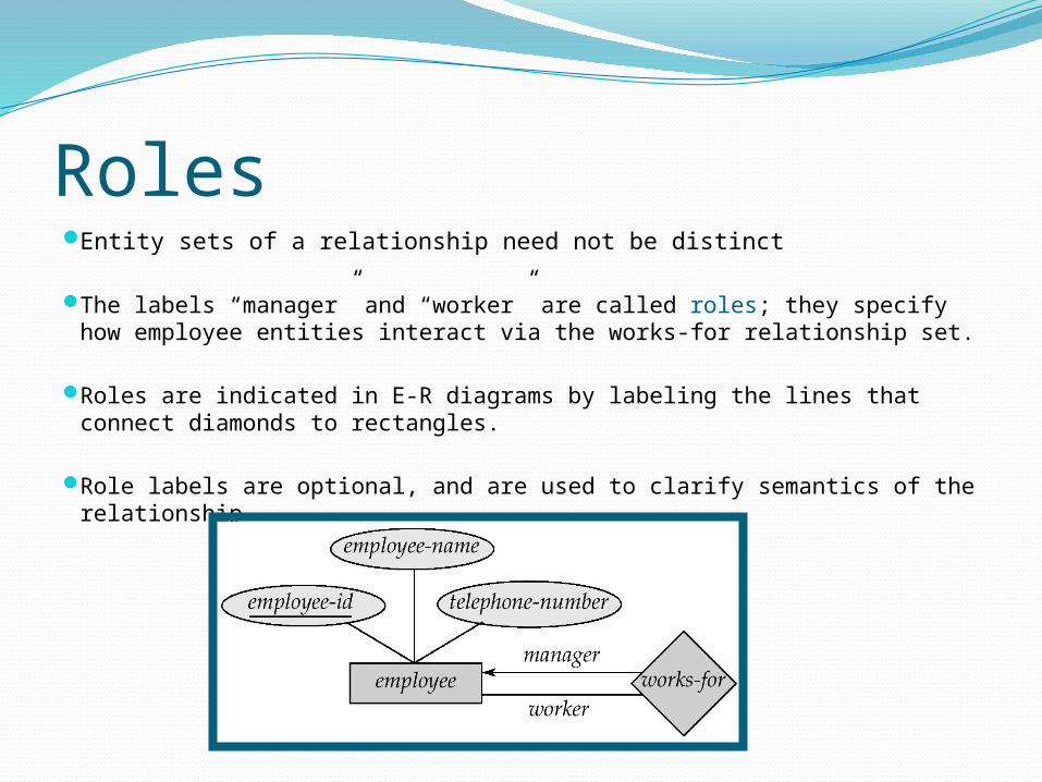
Roles Entity sets of a relationship need not be distinct
The labels “manager” and “worker” are called roles; they specify how employee entities interact via the works-for relationship set.
Roles are indicated in E-R diagrams by labeling the lines that connect diamonds to rectangles.
Role labels are optional, and are used to clarify semantics of the relationship
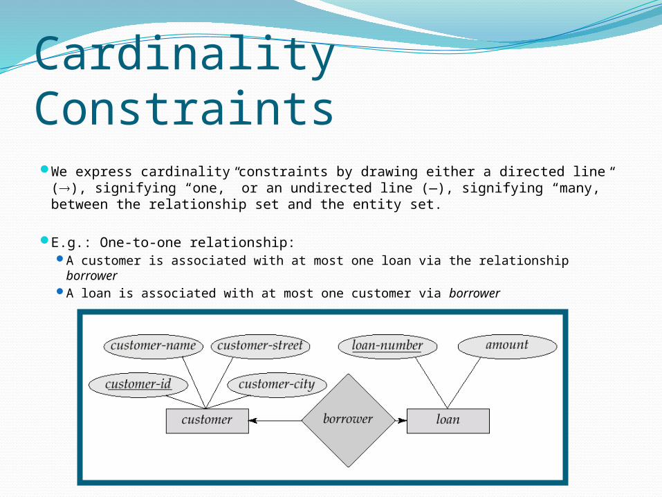
Cardinality Constraints We express cardinality constraints by drawing either a directed line (),
signifying “one,” or an undirected line (—), signifying “many,” between the relationship set and the entity set.
E.g.: One-to-one relationship: A customer is associated with at most one loan via the relationship borrower A loan is associated with at most one customer via borrower
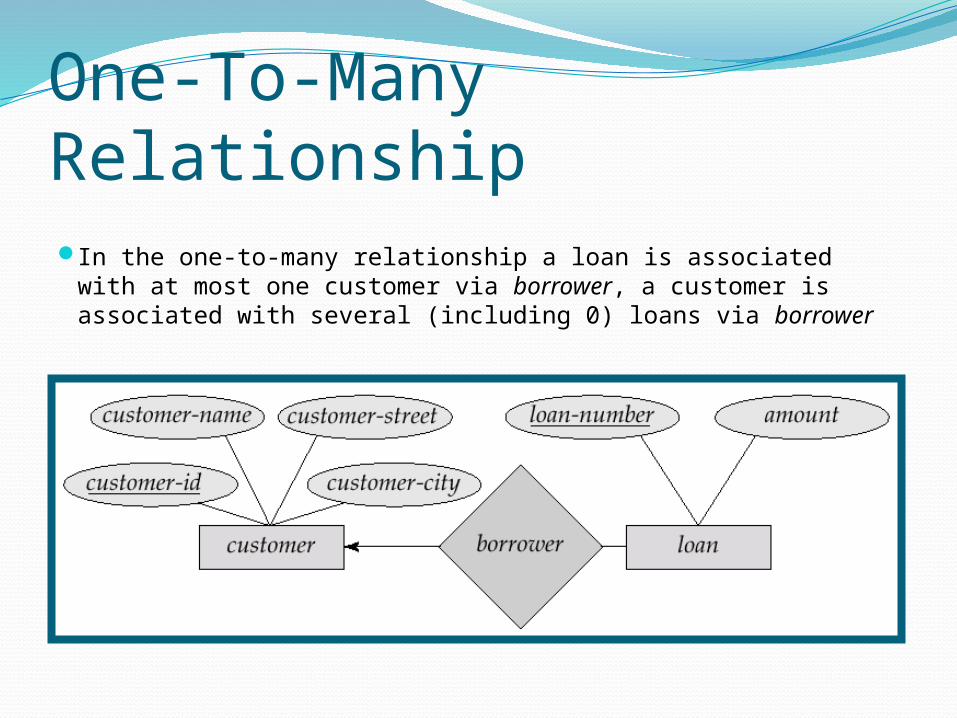
One-To-Many RelationshipIn the one-to-many relationship a loan is associated with at
most one customer via borrower, a customer is associated with several (including 0) loans via borrower
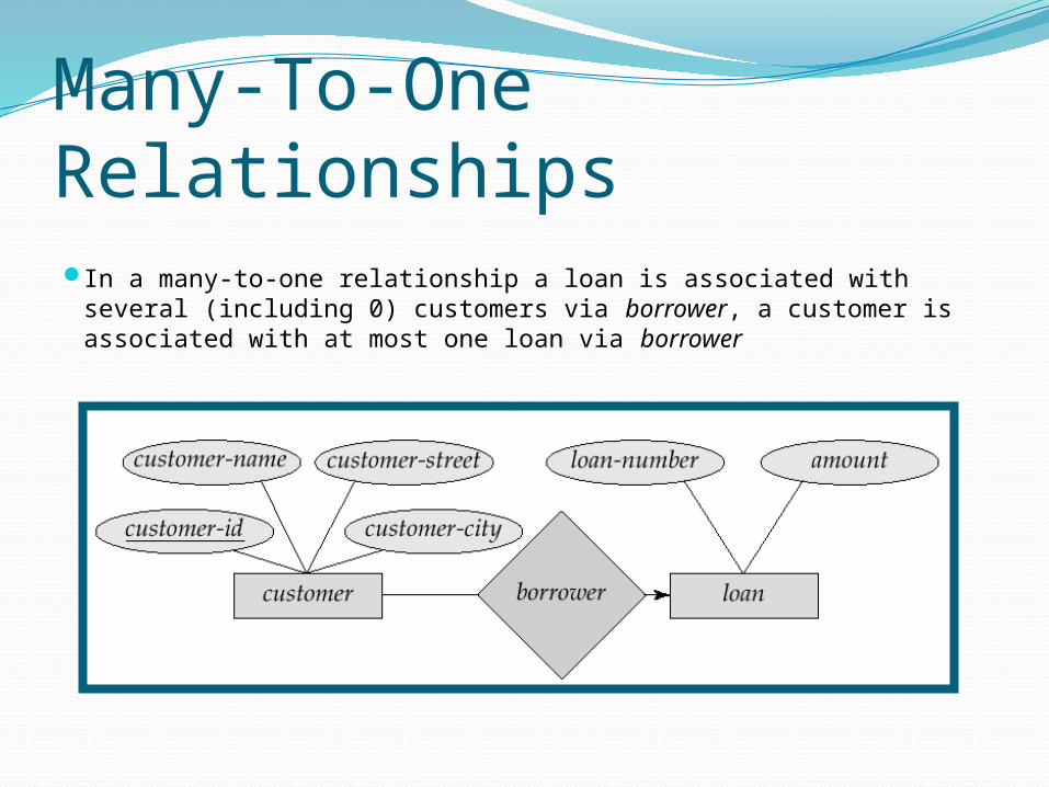
Many-To-One Relationships In a many-to-one relationship a loan is associated with several
(including 0) customers via borrower, a customer is associated with at most one loan via borrower
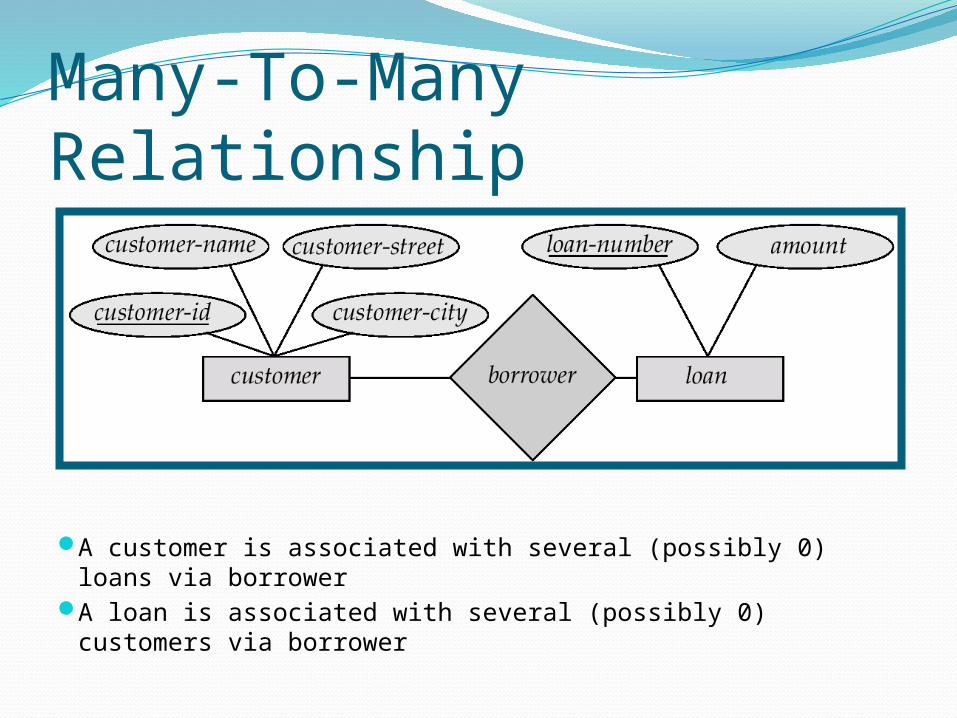
Many-To-Many Relationship
A customer is associated with several (possibly 0) loans via borrower
A loan is associated with several (possibly 0) customers via borrower

Participation of an Entity Set in a Relationship Set Total participation (indicated by double line): every entity in the entity
set participates in at least one relationship in the relationship set E.g. participation of loan in borrower is total
every loan must have a customer associated to it via borrower
Partial participation: some entities may not participate in any relationship in the relationship set E.g. participation of customer in borrower is partial


![[PPT]Entity – Relationship Model (E-R Model)sivasnscedbms.weebly.com/.../entity__relationship_model.ppt · Web viewEntity – Relationship Model (E-R Model) Entity – Relationship](https://img.pdfslide.us/doc/110x75/5b04acac7f8b9a2d518df0c5/pptentity-relationship-model-e-r-model-viewentity-relationship-model.jpg)