Embed Size (px)
Citation preview

ISA–95.00.01–2000
STANDARD
Enterprise-Control System IntegrationPart 1: Models and Terminology
Approved

ISA–95.00.01–2000Enterprise-Control System Integration Part 1: Models and Terminology
ISBN: 1-55617-727-5
Copyright 2000 by the Instrument Society of America. All rights reserved. Not for resale. Printed inthe United States of America. No part of this publication may be reproduced, stored in a retrieval system,or transmitted, in any form or by any means (electronic, mechanical, photocopying, recording, orotherwise), without the prior written permission of the Publisher.
ISA67 Alexander DriveP. O. Box 12277Research Triangle Park, North Carolina 27709USA

– 3 – ISA955.00.01–2000
Preface
This preface, as well as all footnotes and annexes, is included for information purposes and is not part ofISA–95.00.01-2000.
This document has been prepared as part of the service of ISA, the international society for measurementand control, toward a goal of uniformity in the field of instrumentation. To be of real value, this documentshould not be static but should be subject to periodic review. Toward this end, the Society welcomes allcomments and criticisms and asks that they be addressed to the Secretary, Standards and PracticesBoard; ISA; 67 Alexander Drive; P. O. Box 12277; Research Triangle Park, NC 27709; Telephone (919)549-8411; Fax (919) 549-8288; E-mail: [email protected].
The ISA Standards and Practices Department is aware of the growing need for attention to the metricsystem of units in general, and the International System of Units (SI) in particular, in the preparation ofinstrumentation standards. The Department is further aware of the benefits to USA users of ISAstandards of incorporating suitable references to the SI (and the metric system) in their business andprofessional dealings with other countries. Toward this end, this Department will endeavor to introduceSI-acceptable metric units in all new and revised standards, recommended practices, and technicalreports to the greatest extent possible. Standard for Use of the International System of Units (SI): TheModern Metric System, published by the American Society for Testing & Materials as IEEE/ASTM SI 10-97, and future revisions, will be the reference guide for definitions, symbols, abbreviations, andconversion factors.
It is the policy of ISA to encourage and welcome the participation of all concerned individuals andinterests in the development of ISA standards, recommended practices, and technical reports.Participation in the ISA standards-making process by an individual in no way constitutes endorsement bythe employer of that individual, of ISA, or of any of the standards, recommended practices, and technicalreports that ISA develops.
CAUTION — ISA ADHERES TO THE POLICY OF THE AMERICAN NATIONAL STANDARDSINSTITUTE WITH REGARD TO PATENTS. IF ISA IS INFORMED OF AN EXISTING PATENT THAT ISREQUIRED FOR USE OF THE STANDARD, IT WILL REQUIRE THE OWNER OF THE PATENT TOEITHER GRANT A ROYALTY-FREE LICENSE FOR USE OF THE PATENT BY USERS COMPLYINGWITH THE STANDARD OR A LICENSE ON REASONABLE TERMS AND CONDITIONS THAT AREFREE FROM UNFAIR DISCRIMINATION.
EVEN IF ISA IS UNAWARE OF ANY PATENT COVERING THIS STANDARD, THE USER ISCAUTIONED THAT IMPLEMENTATION OF THE STANDARD MAY REQUIRE USE OF TECHNIQUES,PROCESSES, OR MATERIALS COVERED BY PATENT RIGHTS. ISA TAKES NO POSITION ON THEEXISTENCE OR VALIDITY OF ANY PATENT RIGHTS THAT MAY BE INVOLVED IN IMPLEMENTINGTHE STANDARD. ISA IS NOT RESPONSIBLE FOR IDENTIFYING ALL PATENTS THAT MAYREQUIRE A LICENSE BEFORE IMPLEMENTATION OF THE STANDARD OR FOR INVESTIGATINGTHE VALIDITY OR SCOPE OF ANY PATENTS BROUGHT TO ITS ATTENTION. THE USER SHOULDCAREFULLY INVESTIGATE RELEVANT PATENTS BEFORE USING THE STANDARD FOR THEUSER’S INTENDED APPLICATION.
HOWEVER, ISA ASKS THAT ANYONE REVIEWING THIS STANDARD WHO IS AWARE OF ANYPATENTS THAT MAY IMPACT IMPLEMENTATION OF THE STANDARD NOTIFY THE ISASTANDARDS AND PRACTICES DEPARTMENT OF THE PATENT AND ITS OWNER.
ADDITIONALLY, THE USE OF THIS STANDARD MAY INVOLVE HAZARDOUS MATERIALS,OPERATIONS OR EQUIPMENT. THE STANDARD CANNOT ANTICIPATE ALL POSSIBLEAPPLICATIONS OR ADDRESS ALL POSSIBLE SAFETY ISSUES ASSOCIATED WITH USE IN

ISA–95.00.01–2000 – 4 –
HAZARDOUS CONDITIONS. THE USER OF THIS STANDARD MUST EXERCISE SOUNDPROFESSIONAL JUDGMENT CONCERNING ITS USE AND APPLICABILITY UNDER THE USER’SPARTICULAR CIRCUMSTANCES. THE USER MUST ALSO CONSIDER THE APPLICABILITY OFANY GOVERNMENTAL REGULATORY LIMITATIONS AND ESTABLISHED SAFETY AND HEALTHPRACTICES BEFORE IMPLEMENTING THIS STANDARD.
The following served as active members of ISA SP95:
NAME COMPANY
Bill Wray, Chairman Lyondell Chemical Co.Dennis Brandl, Editor Sequencia Corp.David Adler Eli Lilly & Co.William H. Bosler Texas Consultants IncEd Bristol The Foxboro Co.Bernie Brown E.I. du Pont de Nemours and Co.Rick Bullotta Lighthammer Software Corp.John Burnell Hewlett-Packard CanadaDr. Guido Carlo-Stella DeceasedPaul Cherry Cherry Services Inc.Carey Clements Honeywell IACSteven Cloughley Base 10 Systems Inc.Chris Conklin Dow Corning Corp.Lynn Craig Rohm and Haas Co.Richard M. Crossan, Jr. SAP America Inc.Em dela Hostria Rockwell AutomationJoe deSpautz Aurora Biosciences Corp.Daniel Dziadiw TAVA Technologies Inc.David Emerson Yokogawa Corp. of AmericaLarry Falkenau E.I. du Pont de Nemours and Co.Rich Flaherty IBM Corp.Clayton Foster E.I. du Pont de Nemours and Co.Gary L. Funk GLF TechnologyArt Goldberger Jr. Raytheon Consulting and Systems IntegrationJohn Ham Wellspring SolutionsDavid Harrold Cornerstone ControlsBill Hawkins HLQ Ltd.Niels Haxthausen Novo Nordisk EngineeringJohn Hedrick Automation & Control Tech.Sam Herb Moore Process Automation SolutionsDave Imming Fisher-Rosemount Systems Inc.Chris Jaeger Eli Lilly & Co.Jay Jeffreys Oracle Corp.Bruce Jensen Yokogawa Corp. of AmericaGordon Kilgore VAI Automation Inc.Baha Korkmaz Automation Vision Inc.Ken Kovacs TAVA TechnologiesDavid M. Kravitt, CPIM Marcam SolutionsRichard Kowalski Fluor Daniel Inc.Shelby Laurents Fluor Daniel Inc.Robert Long Realtime Information SystemsBill Lorenz Eli Lilly & Co.Eric Marks PriceWaterhouseCoopersRoddy Martin AMR ResearchEd McCutcheon UOP LLC

– 5 – ISA955.00.01–2000
Thomson McFarlane Neles Automation Inc.Paul Moylan Rockwell AutomationMark Muroski ABB Industrial SystemsAlbert Pampel ConsultantJim Parshall Eli Lilly & Co.Saroj Patnaik Fisher-Rosemount Systems Inc.Leif Poulsen Novo Nordisk EngineeringGary Rathwell Fluor Daniel Inc.Richard Sattelmaier Union Carbide Corp.Swarandeep Singh ABB Industrial ASLeon Steinocher Fluor Daniel Inc.Wendy Strauss Moore Process Automation SolutionsKeith Unger TAVA TechnologiesA. Kumar Vakamudi Bechtel Corp.Jean Vieille ConsultantEd Vodopest Advanced Technical SystemsBradley Ward Bradley Ward SystemsArlene Weichert Automated Control Concepts Inc.Oswald Wieser SAP AGTheodore Williams Purdue UniversityGregory Winchester National Electrical Mfrs. Assn.Richard Winslow Sterling Diagnostic Imaging
This standard was approved for publication by the ISA Standards and Practices Board on________________.
NAME COMPANY
M. Zielinski Fisher-Rosemount Systems, Inc.D. Bishop Chevron Petroleum Technology Co.P. Brett Honeywell, Inc.M. Cohen Senior Flexonics, Inc.M. Coppler Ametek, Inc.B. Dumortier Schneider Electric SAW. Holland Southern CompanyA. Iverson Ivy OptiksR. Jones Dow Chemical Co.V. Maggioli Feltronics Corp.T. McAvinew Instrumentation & Control Engineering LLCA. McCauley, Jr. Chagrin Valley Controls, Inc.G. McFarland Honeywell, Inc.R. Reimer Rockwell AutomationJ. Rennie Factory Mutual Research Corp.H. Sasajima Advanced Architecture and TechnologiesR. Webb Altran Corp.W. Weidman Parsons Energy & Chemicals GroupJ. Weiss EPRIJ. Whetstone National Institute of Standards & TechnologyM. Widmeyer EG&GR. Wiegle CANUS Corp.C. Williams Eastman Kodak Co.G. Wood Graeme Wood Consulting

ISA–95.00.01–2000 – 6 –
This standard is dedicated to the memory of Dr. Guido Carlo-Stella, inrecognition of and gratitude for his leadership in earlier work that
made this standard possible.
– 7 – ISA955.00.01–2000
Content
FOREWORD................................................................................................................................................. 9
INTRODUCTION ........................................................................................................................................ 11
1 Scope................................................................................................................................................... 13
2 Normative references .......................................................................................................................... 13
3 Definitions ............................................................................................................................................ 13
4 Enterprise-control system integration overview................................................................................... 16
4.1 Introduction................................................................................................................................... 16
5 Hierarchy Models................................................................................................................................. 18
5.1 Scheduling and control hierarchy ................................................................................................. 18
5.2 Equipment hierarchy model.......................................................................................................... 22
6 Functional data flow model .................................................................................................................. 25
6.1 Functions ...................................................................................................................................... 26
6.2 Information flows .......................................................................................................................... 34
7 Object Model........................................................................................................................................ 39
7.1 Categories of information ............................................................................................................. 39
7.2 Object Model Structure................................................................................................................. 47
7.3 Production capability information ................................................................................................. 48
7.4 Product definition information....................................................................................................... 62
7.5 Production information.................................................................................................................. 65
7.6 Model cross reference.................................................................................................................. 74
Annex A (informative) — Bibliography and Abbreviations.......................................................................... 79
Annex B (informative) — Business drivers and key performance indicators.............................................. 81
Annex C (informative) — Discussion on Models ........................................................................................ 89

ISA–95.00.01–2000 – 8 –
Annex D (informative) — Selected elements of the Purdue Reference Model .......................................... 92
Annex E (informative) — PRM Correlation to MESA International Model and ISA-95.00.01-2000 Models............................................................................... 142

– 9 – ISA955.00.01–2000
FOREWORD
This standard is Part 1 of a multi-part set of standards that defines the interfaces between enterpriseactivities and control activities.
The scope of this Part 1 standard is limited to describing the relevant functions in the enterprise and thecontrol domain and which objects are normally exchanged between these domains. Subsequent parts willaddress how these objects can be exchanged in a robust, secure, and cost-effective manner preservingthe integrity of the complete system.
This Part 1 standard is structured to follow IEC (International Electrotechnical Commission) guidelines.Therefore, the first three clauses present the scope of the standard, normative references, and definitions,in that order.
Clause 4 is informative. The intent is to describe the context of the models in clause 5 and clause 6. Itdefines the criteria used to determine the scope of the manufacturing control system domain. Clause 4,being informative, does not contain the formal definitions of the models and terminology. It describes thecontext to understand the normative clauses.
Clause 5 is normative. The intent is to describe hierarchy models of the activities involved inmanufacturing control enterprises. It defines in general terms the activities that are associated withmanufacturing control and the activities that occur at the business logistics level. It also defines anequipment hierarchy model of equipment associated with manufacturing control. Clause 5, beingnormative, contains formal definitions of the models and terminology.
Clause 6 is normative. The intent is to describe a general model of the functions within an enterprise,which are concerned with the integration of business and control. It defines, in detail, an abstract modelof control functions and, in less detail, the business functions that interface to control. The purpose is toestablish a common terminology for functions involved in information exchange. Clause 6, beingnormative, contains formal definitions of the models and terminology.
Clause 7 is normative. The intent is to define in detail the objects that make up the information streamsdefined in clause 6. The purpose is to establish a common terminology for the elements of informationexchanged. Clause 7, being normative, contains formal definitions of the models and terminology. Theattributes and properties are not formally defined in this clause of the standard.
Annex A is informative. It presents a bibliography of informative references and a list of the abbreviationsused in the document.
Annex B is informative. The intent is to define the business reasons for the information exchangebetween business and control functions. The purpose is to establish a common terminology for thereason for information exchange.
Annex C is informative. It discusses the rational for multiple models.
Annex D is informative. It contains selected elements from the Purdue Reference Model that can be usedto place the functions described in clauses 5 and 6 in context with the entire model.
Annex E is informative. It correlates the Purdue Reference Model to the MESA International model.
This Part 1 standard is intended for those who are:
a) involved in designing, building, or operating manufacturing facilities;

ISA–95.00.01–2000 – 10 –
b) responsible for specifying interfaces between manufacturing and process control systems and othersystems of the business enterprise; or
c) involved in designing, creating, marketing, and integrating automation products used to interfacemanufacturing operations and business systems.
Future parts of this standard may address models of level 3 functions, definitions of level 2-3 interfaces,and data structures for information exchange including the attributes and properties of the data model inclause 7.

– 11 – ISA955.00.01–2000
INTRODUCTION
This Part 1 standard provides standard models and terminology for defining the interfaces between anenterprise’s business systems and its manufacturing control systems. The models and terminologydefined in this standard:
a) emphasize good integration practices of control systems with enterprise systems during the entire lifecycle of the systems;
b) can be used to improve existing integration capabilities of manufacturing control systems withenterprise systems; and
c) can be applied regardless of the degree of automation.
Specifically, this standard provides a standard terminology and a consistent set of concepts and modelsfor integrating control systems with enterprise systems that will improve communications between allparties involved. Some of the benefits produced will:
a) reduce users' times to reach full production levels for new products;
b) enable vendors to supply appropriate tools for implementing integration of control systems toenterprise systems;
c) enable users to better identify their needs;
d) reduce the costs of automating manufacturing processes;
e) optimize supply chains; and
f) reduce life-cycle engineering efforts.
It is not the intent of this standard to:
a) suggest that there is only one way of implementing integration of control systems to enterprisesystems;
b) force users to abandon their current methods of handling integration; or
c) restrict development in the area of integration of control systems to enterprise systems.
This Part 1 standard defines the interface content between manufacturing control functions and otherenterprise functions, based upon the Purdue Reference Model for CIM (hierarchical form) as published byISA.


– 13 – ISA–95.00.01–2000
1 Scope
This Part 1 standard defines the interface content between manufacturing control functions and otherenterprise functions. The interfaces considered are the interfaces between levels 3 and 4 of thehierarchical model defined by this standard. The goal is to reduce the risk, cost, and errors associatedwith implementing these interfaces.
The standard may be used to reduce the effort associated with implementing new product offerings. Thegoal is to have enterprise systems and control systems that inter-operate and easily integrate.
The scope of Part 1 is limited to:
a) a definition of the scope of the manufacturing operations and control domain;
b) a definition of the organization of physical assets of an enterprise involved in manufacturing;
c) a definition of the functions associated with the interface between control functions and enterprisefunctions; and
d) a definition of the information that is shared between control functions and enterprise functions.
2 Normative references
The following normative documents contain provisions that, through reference in this text, constituteprovisions of this Part 1 standard. At the time of publication, the editions indicated were valid. Allnormative documents are subject to revision, and parties to agreements based on this Part 1 standardare encouraged to investigate the possibility of applying the most recent editions of the normativedocuments indicated below. Member organizations of the IEC and ISO (International StandardsOrganization) maintain registers of currently valid normative documents.
a) IEC 61512-1:1997, Batch Control – Part 1: Models and Terminology
b) ANSI/ISA-S88.01-1995, Batch Control – Part 1: Models and Terminology
3 Definitions
For the purposes of this Part 1 standard, the following definitions apply.
3.1 Area:a physical, geographical or logical grouping determined by the site. It may contain process cells,production units, and production lines.
3.2 Available capability:the portion of the production capability that can be attained but is not committed to current or futureproduction.
3.3 Bill of lading:a contract or receipt for goods that a carrier agrees to transport from one place to another and to deliverto a designated person or that it assigns for compensation upon the conditions stated therein.

ISA–95.00.01–2000 – 14 –
3.4 Bill of material:a listing of all the subassemblies, parts, and/or materials that are used in the production of a product.1 Itincludes the quantity of each material required to make a product.
3.5 Bill of resources:a listing of all resources and when in the production process they are needed to produce a product.2 Alsoa listing of the key resources required to manufacture a product, organized as segments of production. Itis often used to predict the impact of activity changes in the master production schedule on the supply ofresources.
3.6 Certificate of analysis:a certification of conformance to quality standards or specifications for products or materials. It mayinclude a list or reference of analysis results and process information. It is often required for custodytransfer of materials.
3.7 Committed capability:the portion of the production capability that is currently in use or is scheduled for use.
3.8 Consumables:resources that are not normally included in bills of material or are not individually accounted for in specificproduction requests.
3.9 Control domain:in this Part 1 standard, control domain is synonymous with the manufacturing operations and controldomain.
3.10 Enterprise:any undertaking, venture, initiative, or business organization with a defined mission.
3.11 Equipment class:a means to describe a grouping of equipment with similar characteristics for purposes of scheduling andplanning.
3.12 Finished goods:final materials on which all processing and production is completed. Finished goods may no longer beunder the manufacturing operations and control domain.
3.13 Finished good waivers:approvals for deviation from normal product specifications.
3.14 In-process waiver requests:requests for waivers on normal production procedures due to deviations in materials, equipment, orquality metrics, where normal product specifications are maintained.
3.15 Manufacturing operations and control domain (MO&C domain):this domain includes all the activities in level 3 and information flows to and from levels 0, 1, and 2 acrossthe boundary to level 4.
______
1 Adapted from Cox III, James F., Blackstone Jr, John H., APICS Dictionary Ninth Edition, APICS - The Educational Society forResource Management, Alexandria, VA. ISBN 1-55822-162-X, 1998.
2 ibid

– 15 – ISA–95.00.01–2000
3.16 Material class:a means to describe a grouping of materials with similar characteristics for purposes of scheduling andplanning.
3.17 Material lot:a uniquely identifiable amount of a material. This describes the actual total quantity or amount of materialavailable, its current state, and its specific property values.
3.18 Material definition:a definition of the properties and characteristics for a substance.
3.19 Material sublot:a uniquely identifiable subset of a material lot, containing quantity and location. May be a single item.
3.20 Personnel class:a means to describe a grouping of persons with similar characteristics for purposes of scheduling andplanning.
3.21 Production capability:a) The highest sustainable output rate that could be achieved for a given product mix, raw materials,
worker effort, plant, and equipment.b) The collection of personnel, equipment, material, and process segment capabilities.c) The total of the current committed, available, and unattainable capability of the production facility.
The capability includes the capacity of the resource.
3.22 Production control:the collection of functions that manages all production within a site or area.
3.23 Production line:a series of pieces of equipment dedicated to the manufacture of a specific number of products orfamilies.3
3.24 Production rules:the information used to instruct a manufacturing operation how to produce a product.
3.25 Production unit:a set of production equipment that converts, separates, or reacts one or more feedstocks to produceintermediate or final products.
3.26 Product segments:the shared information between a plan-of-resources and a production-rule for a specific product. It is alogical grouping of personnel resources, equipment resources, and material specifications required tocarry out the production step.
3.27 Resource:a collection of personnel, equipment, and/or material.
3.28 Unattainable capability:the portion of the production capability that cannot be attained. This is typically due to factors such asequipment unavailability, suboptimal scheduling, or resource limitations.
______
3 Cox III, ibid

ISA–95.00.01–2000 – 16 –
3.29 Work cell:dissimilar machines grouped together to produce a family of parts having similar manufacturingrequirements.
4 Enterprise-control system integration overview (informative)
4.1 Introduction
Successfully addressing the issue of enterprise-control system integration requires identifying theboundary between the enterprise and the manufacturing operations and control domains (MO&C). Theboundary is identified using relevant models that represent functions, physical equipment, informationwithin the MO&C domain, and information flows between the domains.
Multiple models define the functions and integration associated with control and enterprise systems.
a) Hierarchy models that describe the levels of functions and domains of control associated withinmanufacturing organizations are defined in clause 5. These models are based on The PurdueReference Model for CIM, referenced as PRM;4 the MESA International Functional Model;5 and theequipment hierarchy model from the IEC 61512-1 (ANSI/ISA-S88.01-1995) standard.
b) A data flow model that describes the functional and data flows within manufacturing organizations isdefined in clause 6. This model is also based on The Purdue Reference Model for CIM.
c) An object model that describes the information that may cross the enterprise and control systemboundary is defined in clause 7.
DomainDefinitions
Functionsin Domains
Functionsof Interest
InformationFlows of Interest
Categories ofInformation
InformationDefinitions
Figure 1 — Outline of models in the standard
______
4 Selected elements of the Purdue Reference Model for CIM are included in annex D.
5 MESA International, MES Functionality and MRP to MES Data Flow Possibilities - White Paper Number 2 (1994)

– 17 – ISA–95.00.01–2000
This standard provides models and information in multiple levels of detail and abstraction. These levelsare illustrated in Figure 1, which serves as a map to the rest of the document. Each model and diagramincreases the level of detail defined in the previous model.
The models start with a definition of the domain of control systems and the domain of enterprise systems.The domain definitions are contained in clause 5.
Functions within the domains are defined in clauses 5 and 6. Functions of interest that are relevant to thestandard are also given a detailed definition in clause 6. The information flows of interest between therelevant functions are defined in clause 6.2.
The categories of information are defined in clause 7.1. The formal object model of the information ofinterest is defined in clauses 7.3, 7.4, and 7.5.
4.2 Criteria for inclusion in manufacturing operations & control domain
The hierarchy and data flow models describe most of the functions within a manufacturing enterprise.Only some of those functions are associated with manufacturing control and manufacturing controlsystems. The following list defines the criteria used to determine which functions and which informationflows are included in this standard.
a) The function is critical to maintaining regulatory compliance. This includes such factors as safety,environmental, and CGMP (Current Good Manufacturing Practices) compliance.
b) The function is critical to plant reliability.
c) The function impacts the operation phase of a facility’s life, as opposed to the design, construction,and disposal phases of a facility’s life.
d) The information is needed by facility operators in order to perform their jobs.
The information that flows between functions identified as being within the control domain and thoseoutside the control domain defines the enterprise-control system boundary. Information exchangedbetween functions within the control domain and information exchanged between functions outside thecontrol domain are outside the scope of this document. Figure 2 illustrates the enterprise-control systeminterface, as depicted in the data flow model, between control and noncontrol functions; the gray circlesindicate functions that exchange information, and are described in the data flow model. Functionsdepicted as white circles and data flows depicted as dashed lines are those defined as outside the scopeof this standard.

ISA–95.00.01–2000 – 18 –
)XQFWLRQV2XWVLGH�WKH
&RQWURO�'RPDLQ�H�J���3URGXFWLRQ�6FKHGXOLQJ� �H�J���3URGXFWLRQ�6FKHGXOH�DQG�3URGXFWLRQ�5HVXOWV�
,QIRUPDWLRQ�)ORZV�RI�,QWHUHVW
)XQFWLRQV:LWKLQ�WKH
&RQWURO�'RPDLQ�H�J���(TXLSPHQW�0RQLWRULQJ�
(QWHUSULVH�&RQWURO�6\VWHP�%RXQGDU\
)XQFWLRQV�GHWDLOHG
)XQFWLRQV�QRW�GHWDLOHG
'DWD�IORZV�GHWDLOHG
'DWD�IORZV�QRW�GHWDLOHG
Figure 2 — Enterprise-control system interface
5 Hierarchy models
This clause defines the hierarchy models associated with manufacturing control systems and otherbusiness systems.
5.1 Scheduling and control hierarchy
Figure 3 depicts the different levels of a functional hierarchy model: business planning & logistics,manufacturing operations & control, and batch, continuous, or discrete control.6 The model defineshierarchical levels at which decisions are made. The interface addressed in this standard is betweenlevel 4 and level 3 of the hierarchy model. This is generally the interface between plant productionscheduling and operation management and plant floor coordination.
______
6 The figure is a simplified version of the Purdue Hierarchy Model, as shown in figures D-1, D-2, D-3, and D-4 of annex D.

– 19 – ISA–95.00.01–2000
%XVLQHVV�3ODQQLQJ��/RJLVWLFV3ODQW�3URGXFWLRQ�6FKHGXOLQJ�2SHUDWLRQDO�0DQDJHPHQW��HWF
0DQXIDFWXULQJ2SHUDWLRQV��&RQWURO
'LVSDWFKLQJ�3URGXFWLRQ��'HWDLOHG�3URGXFWLRQ6FKHGXOLQJ��5HOLDELOLW\�$VVXUDQFH�����
%DWFK&RQWURO
'LVFUHWH&RQWURO
&RQWLQXRXV&RQWURO
/HYHO��
/HYHO��
/HYHOV�����
,QWHUIDFH�DGGUHVVHGLQ�WKLV�3DUW��VWDQGDUG
Figure 3 — Functional hierarchy
Levels 2, 1, and 0 define the cell or line supervision functions, operations functions, and process controlfunctions. There are several different models for the functions at these levels based on the actualproduction strategy used.
5.1.1 Level 4 activities
Level 4 activities include:
a) Collecting and maintaining raw material and spare parts usage and available inventory, and providingdata for purchase of raw material and spare parts.
b) Collecting and maintaining overall energy use and available inventory and providing data forpurchase of energy source.
c) Collecting and maintaining overall goods in process and production inventory files.
d) Collecting and maintaining quality control files as they relate to customer requirements.
e) Collecting and maintaining machinery and equipment use and life history files necessary forpreventive and predictive maintenance planning.
f) Collecting and maintaining manpower use data for transmittal to personnel and accounting.
g) Establishing the basic plant production schedule.
h) Modifying the basic plant production schedule for orders received, based on resource availabilitychanges, energy sources available, power demand levels, and maintenance requirements.

ISA–95.00.01–2000 – 20 –
i) Developing optimum preventive maintenance and equipment renovation schedules in coordinationwith the basic plant production schedule.
j) Determining the optimum inventory levels of raw materials, energy sources, spare parts, and goods inprocess at each storage point. These functions also include materials requirements planning (MRP)and spare parts procurement.
k) Modifying the basic plant production schedule as necessary whenever major production interruptionsoccur.
l) Capacity planning, based on all of the above activities.
5.1.2 Level 3 activities
Level 3 activities include:
a) Reporting on area production including variable manufacturing costs.
b) Collecting and maintaining area data on production, inventory, manpower, raw materials, spare partsand energy usage.
c) Performing data collection and off-line analysis as required by engineering functions. This mayinclude statistical quality analysis and related control functions.
d) Carrying out needed personnel functions such as: work period statistics (for example, time, task),vacation schedule, work force schedules, union line of progression, and in-house training andpersonnel qualification.
e) Establishing the immediate detailed production schedule for its own area including maintenance,transportation and other production-related needs.
f) Locally optimizing the costs for its individual production area while carrying out the productionschedule established by the level 4 functions.
g) Modifying production schedules to compensate for plant production interruptions that may occur in itsarea of responsibility.
Additional descriptions of the activities contained within level 3 are provided below. The standardassumes all activities not explicitly defined as part of the level 3, control domain, to be part of theenterprise domain. See annex E for a correlation of the activities to the MESA International model.
5.1.2.1 Resource allocation and control
The control domain includes the functionality of managing resources directly associated with control andmanufacturing. The resources include machines, tools, labor skills, materials, other equipment,documents, and other entities that must be available for work to start and to be completed. Themanagement of these resources may include local resource reservation to meet production-schedulingobjectives.
The control domain also ensures that equipment is properly set up for processing, including any allocationneeded for setup. The control domain also is responsible for providing real-time statuses of theresources and a detailed history of resource use.
– 21 – ISA–95.00.01–2000
5.1.2.2 Dispatching production
The control domain includes the functionality of managing the flow of production in the form of jobs,orders, batches, lots, and work orders, by dispatching production to specific equipment and personnel.Dispatch information is typically presented in the sequence in which the work needs to be done and maychange in real time as events occur on the factory floor.
The control domain may alter the prescribed schedules, within agreed upon limits, based on localavailability and current conditions. Dispatching of production includes the ability to control the amount ofwork in process at any point through buffer management and management of rework and salvageprocesses.
5.1.2.3 Data collection and acquisition
The control domain includes the functionality of obtaining the operational production and parametric datathat are associated with the production equipment and production processes.
The control domain also is responsible for providing real-time statuses of the production equipment andproduction processes and a history of production and parametric data.
5.1.2.4 Quality management
The control domain includes the functionality of providing real-time measurements collected frommanufacturing and analysis in order to assure proper product quality control and to identify problemsrequiring attention. It may recommend actions to correct the problem, including correlating the symptoms,actions and results to determine the cause.
It includes SPC/SQC (statistical process control/statistical quality control) tracking and management ofoff-line inspection operations and analysis in laboratory information management systems (LIMS).
5.1.2.5 Process management
The control domain includes the functionality of monitoring production and either automatically corrects orprovides decision support to operators for correcting and improving in-process functions. These functionsmay be intra-operational and focus specifically on machines or equipment being monitored andcontrolled, as well as inter-operational, tracking the process from one operation to the next.
It may include alarm management to make sure factory persons are aware of process changes that areoutside acceptable tolerances.
5.1.2.6 Production planning and tracking
The control domain includes the functionality of providing the status of production and the disposition ofwork. Status information may include personnel assigned to the work; component materials used inproduction; current production conditions; and any alarms, rework, or other exceptions related to theproduct. The functionality includes the capability of recording the production information to allow forwardand backward traceability of components and their use within each end product.
5.1.2.7 Performance analysis
The control domain includes the functionality of providing up-to-the-minute reporting of actualmanufacturing operations results along with comparisons to past history and expected results.Performance results include such measurements as resource utilization, resource availability, product unitcycle time, conformance to schedule, and performance to standards. Performance analysis may include

ISA–95.00.01–2000 – 22 –
SPC/SQC analysis and may draw from information gathered by different control functions that measureoperating parameters.
5.1.2.8 Operations and detailed scheduling
The control domain includes the functionality of providing sequencing based on priorities, attributes,characteristics, and production rules associated with specific production equipment and specific productcharacteristics, such as shape, color sequencing or other characteristics that, when scheduled insequence properly, minimize setup. Operations and detailed scheduling is finite and it recognizesalternative and overlapping/parallel operations in order to calculate in detail the exact time of equipmentloading and adjustment to shift patterns.
5.1.2.9 Document control
The control domain includes some of the functionality of controlling records and forms that must bemaintained with the production unit. The records and forms include work instructions, recipes, drawings,standard operation procedures, part programs, batch records, engineering change notices, shift-to-shiftcommunication, as well as the ability to edit "as planned" and "as built" information. It sends instructionsdown to the operations, including providing data to operators or recipes to device controls. It would alsoinclude the control and integrity of regulatory, documentation, environmental, health and safetyregulations, and SOP information such as corrective action procedures.
5.1.2.10 Labor management
The control domain includes some of the functionality of providing status of personnel in an up-to-theminute time frame. The functions include time and attendance reporting, certification tracking, as well asthe ability to track indirect functions such as material preparation or tool room work as a basis for activity-based costing. Labor management may interact with resource allocation to determine optimalassignments.
5.1.2.11 Maintenance management
The control domain includes some of the functionality of maintaining equipment and tools. The functionsensure the equipment and tools availability for manufacturing. They also may include scheduling forperiodic or preventive maintenance as well as responding to immediate problems. Maintenancemanagement maintains a history of past events or problems to aid in diagnosing problems.
5.2 Equipment hierarchy model
The physical assets of an enterprise involved in manufacturing are usually organized in a hierarchicalfashion as described in Figure 4. This is an expansion of the model described in IEC 61512-1 andANSI/ISA-S88.01-1995, and it includes the definition of assets for discrete and continuous manufacturing.Lower level groupings are combined to form higher levels in the hierarchy. In some cases, a groupingwithin one level may be incorporated into another grouping at that same level.
This model defines the areas of responsibility for the different function levels defined in the hierarchicalmodel. The equipment hierarchy model additionally defines some of the objects utilized in informationexchange between functions.

– 23 – ISA–95.00.01–2000
0D\�FRQWDLQ���RU�PRUH0D\�FRQWDLQ���RU�PRUH
0D\�FRQWDLQ���RU�PRUH
/RZHVW�/HYHOV�RI(TXLSPHQW�7\SLFDOO\
6FKHGXOHG�E\/HYHOV���RU��
/HYHO���DFWLYLWLHVW\SLFDOO\�GHDO�ZLWK�WKHVH�REMHFWV
0D\�FRQWDLQ���RU�PRUH
0D\�FRQWDLQ���RU�PRUH
0XVW�FRQWDLQ���RU�PRUH 0D\�FRQWDLQ���RU�PRUH
(17(535,6(
6,7(
$5($
352'8&7,21/,1(
:25.�&(//
352'8&7,2181,7
352&(66�&(//
81,7
/HYHO���DFWLYLWLHVW\SLFDOO\�GHDO�ZLWK�WKHVH�REMHFWV
/RZHU�OHYHO�HTXLSPHQW�XVHGLQ�UHSHWLWLYH�RU
GLVFUHWH�RSHUDWLRQV�
/RZHU�OHYHO�HTXLSPHQW�XVHG
LQ�EDWFKRSHUDWLRQV�
/RZHU�OHYHO�HTXLSPHQW�XVHGLQ�FRQWLQXRXVRSHUDWLRQV�
Figure 4 — Equipment hierarchy
5.2.1 Enterprise
An enterprise is a collection of one or more sites and may contain sites and areas. The enterprise isresponsible for determining what products will be manufactured, at which sites they will be manufactured,and in general how they will be manufactured.
Level 4 functions are generally dealing at the enterprise and site levels. However, enterprise planningand scheduling may involve areas, cells, lines, or units within an area.
5.2.2 Site
A site is a physical, geographical, or logical grouping determined by the enterprise. It may contain areas,production lines, process cells, and production units. The level 4 functions at a site are involved in localsite management and optimization. Site planning and scheduling may involve cells, lines, or units withinthe areas.
A geographical location and main production capability usually identifies a site. Examples of siteidentifications are “Dallas Expressway Plant” site, “Deer Park Olefins Plant,” and “Johnson CityManufacturing Facility.” Sites are often used for rough-cut planning and scheduling. Sites generallyhave well-defined manufacturing capabilities.
5.2.3 Area
An area is a physical, geographical, or logical grouping determined by the site. It may contain processcells, production units, and production lines. Most level 3 functions occur within the area. The mainproduction capability and geographical location within a site usually identify areas. Examples of areaidentifications are “CMOS Facility,” “North End Tank Farm,” and “Building 2 Electronic Assembly. ”

ISA–95.00.01–2000 – 24 –
Areas generally have well-defined manufacturing capabilities and capacities. The capabilities andcapacities are used for level 3 and level 4 planning and scheduling.
An area is made up of lower-level elements that perform the manufacturing functions. There are threetypes of elements defined that correspond to continuous manufacturing models, discrete (repetitive andnonrepetitive) manufacturing models, and batch manufacturing models. An area may have one or moreof any of the lower-level elements depending upon the manufacturing requirements. Many areas willhave a combination of production lines for the discrete operations, production units for the continuousprocesses, and process cells for batch processes. For example, a beverage manufacturer may have anarea with continuous mixing in a production unit, which feeds a batch process cell for batch processing,feeding a bottling line for a discrete bottling process.
Depending on the planning and scheduling strategy selected, the level 4 functions may stop at the arealevel, or they may schedule the functions of the lower-level elements within the areas.
5.2.4 Production unit
Production units are the lowest level of equipment typically scheduled by the level 4 or level 3 functionsfor continuous manufacturing processes. Production units are composed of lower level elements, suchas equipment modules, sensors, and actuators, but definitions of these are outside the scope of thisstandard. A production unit generally encompasses all of the equipment required for a segment ofcontinuous production, that operates in a relatively autonomous manner. It generally converts, separates,or reacts one or more feedstocks to produce intermediate or final products.
The major processing activity or product generated often identifies the production unit. Examples ofproduction unit identifications are “Catalytic Cracker #1,” “Steam Cracker #59,” and “Alkylation Unit 2."
Production units have well-defined processing capabilities and throughput capacities and these are usedfor level 3 functions. The capacities and capabilities are also often used as input to level 4 scheduling,even if the production units are not scheduled by the level 4 functions.
5.2.5 Production line and work cell
Production lines and work cells are the lowest levels of equipment typically scheduled by the level 4 orlevel 3 functions for discrete manufacturing processes. Work cells are usually only identified when thereis flexibility in the routing of work within a production line. Production lines and work cells may becomposed of lower-level elements, but definitions of these are outside the scope of this document.
The major processing activity often identifies the production line. Examples of production lineidentifications are “Bottling Line #1,” “Capping Line #15,” CMOS Line #2,” and “Water Pump AssemblyLine #4.”
Production line and work cells have well-defined manufacturing capabilities and throughput capacitiesand these are used for level 3 functions. The capacities and capabilities are also often used as input tolevel 4 scheduling, even if the production lines and work cells are not scheduled by the level 4 functions.
5.2.6 Process cell and unit
Process cells and units are the lowest level of equipment typically scheduled by the level 4 and level 3functions for batch manufacturing processes. Units are usually only identified at level 3 and 4 if there isflexibility in the routing of product within a process cell. The definitions for process cells and units arecontained in the IEC 61512-1 and ANSI/ISA-S88.01-1995 standards.

– 25 – ISA–95.00.01–2000
The major processing capability or family of products produced often identifies the process cell.Examples of process cell identifications are “Mixing Line #5,” “West Side Glue Line,” and “Detergent Line13.”
Process cells and units have well-defined manufacturing capabilities and batch capacities and these areused for level 3 functions. The capacities and capabilities may also be used as input data for level 4scheduling, even if the process cells or units are not scheduled by the level 4 functions.
6 Functional data flow model
This clause presents:
a) The functions of an enterprise involved with manufacturing.
b) The information flows between the functions that cross the enterprise-control interface.
The enterprise-control interface is described using a data flow model. The model is defined using theYourdon-Demarco7 notational methodology.
Table 1 defines the Yourdon notation used in the functional model.
Table 1 — Yourdon notation used
Symbol Definition
Function(4.0)
A function is represented as a labeled ellipse. A function is a group of tasks that canbe classified as having a common objective. Functions are organized in a hierarchicalmanner and are identified with a name and a number. The number represents anidentification of the data model hierarchy level.
ExternalEntity
An external entity is represented as a labeled rectangle. An external entity is acomponent outside the model boundaries that sends data to and/or receives datafrom the functions.
Data Flow Name
A solid line with an arrow represents a grouping of data that flows between functions,data stores, or external entities. The data are defined in the enterprise-controlintegration model. All solid lines have a name for the data flows.
A data flow at one level of the functional hierarchy may be represented by one ormore flows at the lower level of the hierarchy.
A dashed line with an arrow represents a grouping of data that flows betweenfunctions, data stores, or external entities. The data are not pertinent to theenterprise-control integration model, but are shown to illustrate the context offunctions. Dashed line data flows without names are not identified in this model, butare defined in annex D.
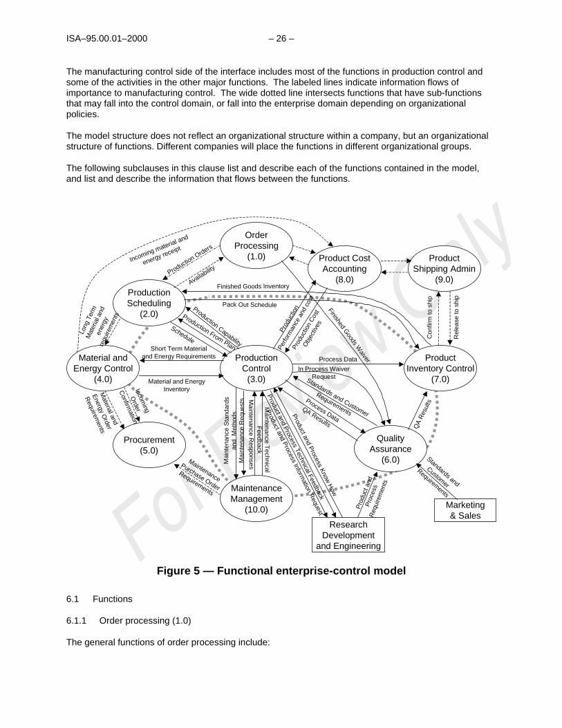
The functional model is depicted in Figure 5. The wide dotted line illustrates the boundary of theenterprise-control interface. The line is equivalent to the level 3 - level 4 interface defined in clause 5.1.
______
7 Adapted from STRUCTURED ANALYSIS AND SYSTEM SPECIFICATION by DeMarco, 1978, Prentice-Hall, Inc., Upper Saddle River, NJ.
ISA–95.00.01–2000 – 26 –
The manufacturing control side of the interface includes most of the functions in production control andsome of the activities in the other major functions. The labeled lines indicate information flows ofimportance to manufacturing control. The wide dotted line intersects functions that have sub-functionsthat may fall into the control domain, or fall into the enterprise domain depending on organizationalpolicies.
The model structure does not reflect an organizational structure within a company, but an organizationalstructure of functions. Different companies will place the functions in different organizational groups.
The following subclauses in this clause list and describe each of the functions contained in the model,and list and describe the information that flows between the functions.
Procurement(5.0)
ProductionScheduling
(2.0)
Material andEnergy Control
(4.0)
ProductInventory Control
(7.0)
Product CostAccounting
(8.0)
QualityAssurance
(6.0)
ResearchDevelopment
and Engineering
ProductShipping Admin
(9.0)
OrderProcessing
(1.0)
Marketing& Sales
ProductionControl
(3.0)
MaintenanceManagement
(10.0)
Pack Out Schedule
Finished Goods Inventory
Finished Goods W
aiverProcess Data
Short Term Materialand Energy Requirements
Material and EnergyInventory
Production Capability
Production From Plan
Schedule
Incoming material and
energy receipt
Prod
uctio
n C
ost
Obj
ectiv
es
Prod
uctio
n
Perfo
rman
ce a
nd c
ost
Con
firm
to s
hip
Rel
ease
to s
hip
QA
Res
ults
Pro
duct
and
Pro
cess
Req
uire
men
ts
Standards and
Customer
Requirements
Standards and Customer
Requirements
In Process WaiverRequest
Process Data
QA Results
Product and P
rocess Know
How
Product and P
rocess Technical Feedback
Ma i
nten
ance
Sta
ndar
dsa n
d M
etho
d s
Mainte nance T
echnic alF
eed back
Maintenance
Purchase Order
Requirements
Material and
Energy O
rder
Requirem
ents
Incoming
Order
Confirm
ation
Long
Ter
m
Mat
eria
l and
ener
gyre
quire
men
ts
Production Orders
Availability
Product and P
rocess Information R
equestM
aint
e nan
ce R
eque
sts M
ainten ance Respons es
Figure 5 — Functional enterprise-control model
6.1 Functions
6.1.1 Order processing (1.0)
The general functions of order processing include:
– 27 – ISA–95.00.01–2000
a) Customer order handling, acceptance and confirmation
b) Sales forecasting
c) Waiver and reservation handling
d) Gross margin reporting
e) Determining production orders
There is generally no direct interface between the functions of order processing and the manufacturingcontrol functions.
6.1.2 Production scheduling (2.0)
Production scheduling functions interface to the manufacturing control system functions through aproduction schedule, actual production information, and production capability information. Thisinformation exchange is defined in the production control functions.
Detailed scheduling, within an area, is defined as a control function.
The general functions of production scheduling include:
a) Determine production schedule
b) Identify long-term raw material requirements
c) Determine pack-out schedule for end products
d) Determine available product for sales
The information generated or modified by the production scheduling functions includes:
a) The production schedule
b) The actual production versus the planned production
c) The production capacity and resource availability
d) Current order status
6.1.3 Production control (3.0)
The production control functions encompass most of the functions associated with manufacturing control.The functions of production control include:
a) Controlling the transformation of raw materials into end product in accordance with productionschedule and production standards
b) Performing plant engineering activities and updating of process plans
c) Issuing requirements for raw materials
d) Producing reports of performance and costs
ISA–95.00.01–2000 – 28 –
e) Evaluating constraints to capacity and quality
f) Self-test and diagnostics of production and control equipment
g) Creating production standards and instructions for SOPs (standard operating procedures), recipes,and equipment handling for specific processing equipment
The main functions in production control include process support engineering, operations control, andoperations planning.
6.1.3.1 Process support engineering
The functions of process support engineering include:
a) Issuing requests for modification or maintenance
b) Coordinating maintenance and engineering functions
c) Providing technical standards and methods to operations and maintenance functions
d) Following up on equipment and process performance
e) Providing technical support to operators
f) Following up on technological developments
The functions of process support engineering generate or modify the following information for use in othercontrol functions:
a) Minor equipment and process modifications; this may include new design drawings
b) Instructions on how to handle equipment; this may include standard operating procedures
c) Instructions on how to make products; this includes production rules and the standard materials,equipment, and other resources used
d) Material safety data sheets (MSDS)
e) Instructions on how to install equipment; this may include vendor equipment
f) Environmental and safety operating limits and constraints
g) Engineering standards for process equipment design techniques and process operational methods,and online operating instructions
h) Instructions for plant trials or plant tests
6.1.3.2 Operations control
Operations control is the collection of functions that manages all production within a site or area.
The functions of production control include:
a) Producing the product according to schedule and specifications

– 29 – ISA–95.00.01–2000
b) Reporting production, process, and resource information
c) Monitoring equipment, validating operational measurements, and determining the need formaintenance
d) Preparing equipment for maintenance and returning it to service after maintenance
e) Performing diagnostics and self-check of production and control equipment
f) Balancing and optimizing production within the site or area
g) May include local site or area labor management and document management
The functions of production control generate or modify the following information for use in other controlfunctions:
a) Status of production requests
b) Selected production data, such as data to calculate production cost, and production performance
c) Selected process data, such as equipment performance feedback
d) Status of resources
e) Status of maintenance work order requests
f) Requests for maintenance
g) Diagnostic and self-test results
h) Process history
i) Requests for process support engineering support
j) Request for analysis of material
6.1.3.3 Operations planning
The functions of operations planning include:
a) Setting up a short-term production plan based on the production schedule
b) Checking the schedule against raw material availability and product storage capacity
c) Checking the schedule against equipment and personnel availability
d) Determining the percent of capacity status
e) Modifying the production plan hourly to account for equipment outage, manpower and raw materialsavailability
The functions of operations planning generate or modify the following information for use in other controlfunctions:
a) Material and energy inventory report
ISA–95.00.01–2000 – 30 –
b) Material and energy requirements required to meet the production plan
c) Site or area production plan for operations control
d) Available capability of the production resources
6.1.4 Material and energy control (4.0)
The functions of materials and energy control include:
a) Managing inventory, transfers, and quality of material and energy
b) Generating requests for purchasing of materials and energy based on short- and long-termrequirements
c) Calculating and reporting inventory balance and losses of raw material and energy utilization
d) Receiving incoming material and energy supplies and requesting quality assurance tests
e) Notifying purchasing of accepted material and energy supplies
The functions of materials and energy control generate or modify the following information for use in othercontrol functions:
a) Material and energy order requests
b) Incoming confirmation of received materials and energy
c) Material and energy inventory report
d) Manual and automated transfer instructions for operations control
Some of the functions within material and energy control may be inside the control domain, based onlocal organizational structures. Therefore, selected data flows into and out of material and energy controlare defined because they may cross the enterprise-control system boundary.
6.1.5 Procurement (5.0)
The functions of procuring resources include:
a) Placing orders with suppliers for raw materials, supplies, spare parts, tools, equipment and otherrequired materials
b) Monitoring progress of purchases and reporting to requisitioners
c) Releasing incoming invoices for payment after arrival and approval of goods
d) Collecting and processing of unit requests for raw materials, spare parts, etc., for order placement tovendors
The functions of procurement generate or modify the following information for use in other controlfunctions:
a) Expected material and energy delivery schedules

– 31 – ISA–95.00.01–2000
6.1.6 Quality assurance (6.0)
The functions of quality assurance include:
a) Testing and classification of materials
b) Setting standards for material quality
c) Issuing standards to manufacturing and testing laboratories in accordance with requirements fromtechnology, marketing and customer services
d) Collecting and maintaining material quality data
e) Releasing material for further use (delivery or further processing)
f) Certifying that product was produced according to standard process conditions
g) Checking of product data versus customer's requirements and statistical quality control routines toassure adequate quality before shipment
h) Relaying material deviations to process engineering for re-evaluation to upgrade processes
The functions of quality assurance generate or modify the following information for use in other controlfunctions:
a) Quality assurance test results
b) Approval to release materials, or waivers on compliance
c) Applicable standards and customer requirements for material quality
Some of the functions within quality assurance may be inside the control domain, based on localorganizational structures; for example, quality assurance requests. Therefore, selected data flows intoand out of quality assurance are defined because they may cross the enterprise-control system boundary.
6.1.7 Product inventory control (7.0)
The functions of product inventory control include:
a) Managing inventory of finished products
b) Making reservations for specific product in accordance with product selling directives
c) Generating the pack-out end product in accordance with delivery schedule
d) Reporting on inventory to production scheduling
e) Reporting on balance and losses to product cost accounting
f) Arranging physical loading/shipment of goods in coordination with product shipping administration
The functions of product inventory control generate or modify the following information for use in othercontrol functions:
a) Finished goods inventory

ISA–95.00.01–2000 – 32 –
b) Inventory balances
c) Pack-out schedule
d) Release to ship
e) Confirm to ship
f) Requirements
Some of the functions within product inventory control may be inside the control domain, based on localorganizational structures. Therefore, selected data flows into and out of product inventory control aredefined because they may cross the enterprise-control system boundary.
6.1.8 Product cost accounting (8.0)
The functions of cost accounting include:
a) Calculating and reporting on total product cost
b) Reporting cost results to production for adjustment
c) Setting cost objectives for production
d) Collecting raw material, labor, energy and other costs for transmission to accounting
e) Calculating and reporting on total production cost, reporting cost results to production for adjustment
f) Setting cost objectives for materials and energy supply and distribution
The functions of cost accounting generate or modify the following information for use in other controlfunctions:
a) Cost objectives to production
b) Performance and costs from production
c) Parts and energy incoming to accounting from material and energy control
6.1.9 Product shipping administration (9.0)
The functions of product shipping administration include:
a) Organizing transport for product shipment in accordance with accepted orders requirements
b) Negotiating and placing orders with transport companies
c) Accepting freight items on site and releasing material for shipment
d) Preparing accompanying documents for shipment (BOL, customs clearance)
e) Confirming shipment and releasing for invoicing to general accounting
f) Reporting on shipping costs to product cost accounting

– 33 – ISA–95.00.01–2000
6.1.10 Maintenance management (10.0)
The functions of maintenance management include:
a) Providing maintenance for existing installations
b) Providing preventative maintenance program
c) Providing equipment monitoring to anticipate failure, including self-check and diagnostic programs
d) Placing purchase order requests for materials and spare parts
e) Developing maintenance cost reports, and coordinating outside contract work effort
f) Providing status and technical feedback on performance and reliability to process supportengineering
The functions of maintenance management generate or modify the following information for use in othercontrol functions:
a) Maintenance schedules that specify the plan for future work orders
b) Maintenance work orders that specify specific equipment to be taken out of service and available formaintenance functions
c) Diagnostic and self-test requests to be performed on the equipment
Some of the functions within maintenance management may be inside the control domain, based on localorganizational structures. Therefore selected data flows into and out of maintenance management aredefined because they may cross the enterprise-control system boundary.
6.1.11 Research, development, and engineering
The general functions of research, development and engineering include:
a) Development of new products
b) Definition of process requirements
c) Definition of product requirements, as relates to the production of the products
6.1.12 Marketing and sales
The general functions of marketing and sales include:
a) Generating sales plans
b) Generating marketing plans
c) Determining customer requirements for products
d) Determining requirements and standards for products
e) Interacting with customers

ISA–95.00.01–2000 – 34 –
6.2 Information flows
The information flows between the functions that are labeled in Figure 5 are listed below. The informationin the information flows is defined in clause 7.
6.2.1 Schedule
The schedule information flows from the production scheduling (2.0) functions to the production control(3.0) functions.
This contains the information, to production, on what product is to be made, how much is to be made, andwhen it is to be made. Elements of the schedule information are defined in clauses 7.5.1 and 7.5.2, andare shown in Figure 22.
6.2.2 Production from plan
The production-from-plan information flows from the production control (3.0) functions to the productionscheduling (2.0) functions.
This contains information about the current and completed production results from execution of the plan.It contains what was made, how much was made, how it was made, and when it was made. Elements ofthe production-from-plan information are defined in clauses 7.5.3 and 7.5.4, and shown in Figure 23.
6.2.3 Production capability
The production capability information flows from the production control (3.0) functions to the productionscheduling (2.0) functions.
Production capability information defines the current committed, available, and unattainable capability ofthe production facility. This includes materials, equipment, labor, and energy. Elements of the productioncapability information are defined in clause 7.1.1 and shown in Figure 15.
6.2.4 Material and energy order requirements
The material and energy order requirement information flows from the material and energy control (4.0)functions to the procurement (5.0) functions.
Material and energy order requirements define future requirements for materials and energy required tomeet short-term and long-term requirements based on the current availability.
There are no object models for the material and energy order requirements, but the information may usethe definitions relating to material and energy detailed in the clause 7 object model.
6.2.5 Incoming order confirmation
The incoming order confirmation information flows from the material and energy control (4.0) functions tothe procurement (5.0) functions.
Incoming order confirmations are the notification that the material or energy has been received.
This information is not detailed in the clause 7 object model because it does not cross the interfacebetween the enterprise and control domains.

– 35 – ISA–95.00.01–2000
6.2.6 Long-term material and energy requirements
The long-term material and energy requirements information flows from the production scheduling (2.0)functions to the material and energy control (4.0) functions.
The long-term material and energy requirements are time-sequenced definitions of material and energyresources that will be needed for planned production.
There are no object models for the long-term material and energy requirements, but the information mayuse the definitions relating to material and energy detailed in the clause 7 object model.
6.2.7 Short-term material and energy requirements
The short- term material and energy requirements information flows from the production control (3.0)functions to the material and energy control (4.0) functions.
The short- term material and energy requirements are requirements for resources that are needed forcurrently scheduled or executing production. These may include:
a) Requests for materials that may include deadlines
b) Reservations for materials
c) Indications of actual consumption
d) Release of reservations
e) Adjustments to consumption
Material is represented in Figure 19 in clause 7.3.4 and the material and energy requirements arerepresented in Figure 22 in clause 7.5.2.
6.2.8 Material and energy inventory
The material and energy inventory information flows from the material and energy control (4.0) functionsto the production control (3.0) functions.
The material and energy inventory information flows are the currently available material and energy thatcan be used for short-term planning and for production. This information deals with raw materials.Material and energy inventory information is defined in clause 7.3.4.
6.2.9 Production cost objectives
The production cost objectives information flows from the product cost accounting (8.0) functions to theproduction control (3.0) functions.
Production cost objectives are the production performance targets in terms of resources. This could berelated to a product or to a process. This may include materials, labor hours, energy, equipment usage,or actual costs. Elements of the production cost objectives are defined in clauses 7.1.2 and 7.4 andshown in Figure 21.

ISA–95.00.01–2000 – 36 –
6.2.10 Production performance and costs
The production performance and costs information flows from the production control (3.0) functions to theproduct cost accounting (8.0) functions.
Production performance and costs are the actual use and results associated with specific productionactivities. This includes materials, labor hours, energy, and equipment usage. Results may be identifiedby products, by-products, co-products, and scrap. This information would be in sufficient detail to identifyall costs by product, co-products, and scrap.
6.2.11 Incoming material and energy receipt
The incoming material and energy receipt information flows from the material and energy control (4.0)functions to the product cost accounting (8.0) functions.
Incoming material and energy receipt is the notification that the material or energy has been received andadditional information needed for cost accounting. This may also include the BOL (bill of lading), MSDS(material safety data sheet), and COA (certificate of analysis). This information is coordinated with theincoming order confirmation (clause 6.2.5) information flow.
This information is not detailed in the clause 6 object model because it generally does not cross theinterface between the enterprise and control domains.
6.2.12 Quality assurance results
The quality assurance (QA) results information flows from the quality assurance (6.0) functions to theproduct inventory control (7.0) functions and the production control, operations control (3.2) functions.
Quality assurance results are the results from QA tests performed on raw materials, in-process materials,or products. Quality assurance results may concern tests performed in the product or in-process testsperformed in a particular segment of production. Quality assurance results may include granting of in-process waivers.
A positive QA result may be required before product inventory management may ship a product. Apositive QA result may be required before production control transfers product to product inventorycontrol.
6.2.13 Standards and customer requirements
The standards and customer requirements information flows from the marketing and sales functions tothe quality assurance (6.0) functions, and from quality assurance to production control (3.0).
Standards and customer requirements are the specific values for attributes of the product that satisfy thecustomer needs. This may include specific processing specifications as well as material properties. Thisinformation may result in changes or additions to material, equipment, and personnel properties andassociated tests (see clause 7.3).
6.2.14 Product and process requirements
The product and process requirements information flows from the research, development and engineering(RD&E) functions to the quality assurance (6.0) functions.
The product and process requirements define how to make a product. This corresponds to general or siterecipes in batch manufacturing, assembly instructions and drawings in discrete manufacturing, and

– 37 – ISA–95.00.01–2000
process descriptions in continuous manufacturing. Information about specific equipment, personnel, andmaterial requirements may be specified according to the models in clause 7.4.
6.2.15 Finished goods waiver
Finished goods waiver information flows from the order processing (1.0) functions to the qualityassurance (6.0) functions.
Finished goods waivers are approvals for deviation from normal product specifications. Finished goodswaivers may be negotiated customer deviations from specifications defined in the standards andcustomer requirements (clause 6.2.13).
6.2.16 In-process waiver request
In-process waiver request information flows from production control (3.0) to the quality assurance (6.0)functions.
In-process waiver requests are requests for waivers on normal production procedures due to deviations inmaterials, equipment, or quality metrics, where normal product specifications are maintained. Theresponse to the request is in the quality assurance results.
6.2.17 Finished goods inventory
The finished goods inventory information flows from the product inventory control (7.0) functions to theproduction scheduling (2.0) functions.
The finished goods inventory is information on the current inventory of finished goods that is maintainedby product inventory control. This may include quantity, quality, and location information that can be usedfor scheduling of new production, and as feedback on previously scheduled production. This is the totalfinished product available for distribution or shipment. This information is described in clause 7.3.4.
6.2.18 Process data
The process data information flows from the production control (3.0) functions to the product inventorycontrol (7.0) functions and the quality assurance (6.0) functions.
Process data is information about production processes, as related to specific products and productionrequests, and is described in clauses 7.5.3 and 7.5.4. Process data may be used by quality assurance aspart of the QA functions, and may be used by product inventory control where this information is neededas part of the finished product deliverables.
6.2.19 Pack out schedule
The pack out schedule information flows from the production scheduling (2.0) functions to the productinventory control (7.0) functions.
A pack out schedule is the consolidation of produced items of one or more SKUs (stock-keeping unit) fordelivery to customers, inventory, or others.
6.2.20 Product and process know-how
The product and process know how information flows from the research, development and engineering(RD&E) functions to the production control (3.0) functions.

ISA–95.00.01–2000 – 38 –
Product and process know-how includes standard operating procedures, recipes, critical safety limits, andanalytical methods. This may be generated in response to an operations requests or originated by RD&Efor new products and processes.
Elements of the product and process know-how information are defined in clause 7.4 and in Figure 21.
6.2.21 Product and process information request
The product and process information request flows from the production control (3.0) functions to theRD&E functions.
A product and process information request is a request for new or modified product definitions andprocess definitions.
6.2.22 Maintenance requests
The maintenance request information flows from the production control (3.0) functions to the maintenancemanagement (10.0) functions.
Maintenance requests are requests for a maintenance function. This may be a planned request or anunplanned request due to an unplanned event, such as a lightning strike on a transformer.
6.2.23 Maintenance responses
The maintenance response information flows from the maintenance management (10.0) functions to theproduction control (3.0) functions.
Maintenance responses are the logged status or completion of routine, scheduled, or unplannedmaintenance.
6.2.24 Maintenance standards and methods
Maintenance standards and methods information flows from the production control (3.0) functions to themaintenance management (10.0) functions.
Maintenance standards and methods are accepted practices and procedures that maintenance mustfollow in performing its functions.
6.2.25 Maintenance technical feedback
Maintenance technical feedback information flows from the maintenance management (10.0) functions tothe production control (3.0) functions.
Maintenance technical feedback is information about the performance and reliability of productionequipment and may include reporting on performed maintenance. Reports on maintenance may includescheduled, preventive, or predictive.
6.2.26 Product and process technical feedback
Product and process technical feedback information flows from the production control (3.0) functions tothe RD&E functions.
Product and process technical feedback is information about the performance of production equipmentand product. This information generally results from performance tests and study requests to operationscontrol.

– 39 – ISA–95.00.01–2000
6.2.27 Maintenance purchase order requirements
Maintenance purchase order requirements information flows from the maintenance management (10.0)functions to the procurement (5.0) functions.
Maintenance purchase order requirements is information about materials and supplies required toperform maintenance tasks.
6.2.28 Production order
Production order information flows from order processing (1.0) functions to production scheduling (2.0)functions.
Production order is information about accepted customer orders that defines work for the plant.
6.2.29 Availability
Availability information flows from the production scheduling (2.0) functions to the order processing (1.0)functions.
Availability is information about the plant's ability to fulfill the order.
6.2.30 Release to ship
Release to ship information flows from the product shipping administration (9.0) functions to the productinventory control (7.0) functions.
Release to ship is information about the permission to ship the product.
6.2.31 Confirm to Ship
Confirm to ship information flows from the product inventory control (7.0) functions to the product shippingadministration (9.0).
Confirm to ship is information about the actual shipment of product.
7 Object Model
Clause 7.1 is an overview of the information contained in the object model and provides a context for theobject models. It defines the general categories of information in clauses 7.3, 7.4, and 7.5.
7.1 Categories of information
Most of the information described in the clause 6 model falls into three main areas:
a) Information required to produce a product
b) Information about the capability to produce a product
c) Information about actual production of the product
Some information in each of these three areas must be shared between the manufacturing controlsystems and the other business systems, as illustrated in Figure 6. Venn diagrams are used to illustratethe overlap of information. This standard is only concerned with the overlapping information in the Venndiagrams, and with defining a model and common terminology for that information.

ISA–95.00.01–2000 – 40 –
Business Planning& Logistics Information
Plant Production Scheduling,Operational Management, etc.
Manufacturing Operations& Control Information
Area Supervision, Production, Scheduling,Reliability, Assurance, etc.
ProductDefinition
Information(How tomake aproduct)
ProductionCapability
Information(What isavailable)
ProductionInformation
(What tomake andresults)
Figure 6 — Areas of information exchange
7.1.1 Production capability information
There are three main areas of information about the production capability that have significant overlap.The three areas of information are production capability information, maintenance information, andcapability scheduling information. Figure 7 illustrates the overlapping information.

– 41 – ISA–95.00.01–2000
MaintenanceInformation
CapabilitySchedulingInformation
ProductionCapability
Information Scheduled production equipment availability
Preventive/predictive maintenance information
Production capability
Production equipment status
Figure 7 — Production capability information
7.1.1.1 Production capability information
For each site, area, and element within the area there is a definition of the production capability of thepersonnel, equipment, and materials.
The production capability information includes the current state of what is available as updated by theproduction capability model in Figure 15.
7.1.1.2 Maintenance information
For each site, area, and element within the area there is a definition of the equipment as required formaintenance. This includes maintenance records and other information that is not part of the productioncapability model.
The maintenance information includes the current maintenance state of the equipment, as defined byinformation in the production capability model shown in Figure 15.
7.1.1.3 Capability scheduling information
The capability scheduling information contains the process segments available for the product unit,process cell, or production line.
For each site, area, and equipment element within the area there is a definition of the productioncapability of the personnel, equipment, and materials needed for scheduling of production.

ISA–95.00.01–2000 – 42 –
7.1.1.4 Production equipment status
Production equipment status is information shared between the equipment’s capacity and capabilitymodel and the maintenance model. This includes the definition of the equipment, the current status of theequipment, and the usage history of the equipment.
7.1.1.5 Production capability
Production capability is defined as the information shared between the production capability model andthe capacity scheduling model. This includes the definition of the capacity, and current status of thepersonnel, equipment, and materials.
7.1.1.6 Scheduled production equipment availability
Scheduled production equipment availability is a dynamic interaction of production capability information,maintenance information, and capability scheduling information that allows forecasting of scheduledproduction equipment availability.
7.1.1.7 Preventive/predictive maintenance information
Preventive/predictive maintenance information is the correlation of equipment health and maintenancerequirements with capability scheduling information as to align maintenance processes and adjust thecapability scheduling information during the maintenance processes.
7.1.2 Product definition information
There are three main areas of information required for production of a specific product that havesignificant overlap. The three areas are information for scheduling, material information, and productionrules. Figure 8 illustrates the overlapping information.
Bill OfResources
Bill OfMaterial
Production information on a specific product withthe detail required for actual production.
ProductProduction
Rules Material information on a specific product, includinginformation not related to production (e.g. shippingmaterials)
Scheduling information on a specific product,including information that is not related to production(e.g. material order lead times)
Product Segment
Figure 8 ˘— Production definition information
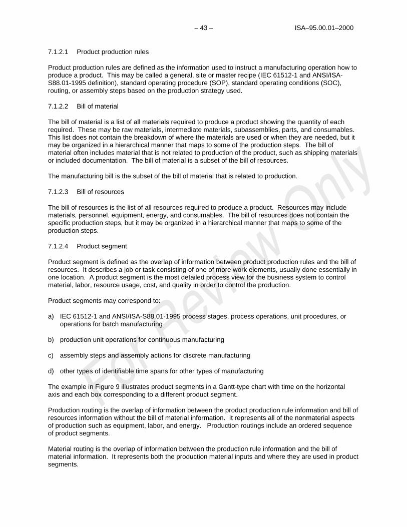
– 43 – ISA–95.00.01–2000
7.1.2.1 Product production rules
Product production rules are defined as the information used to instruct a manufacturing operation how toproduce a product. This may be called a general, site or master recipe (IEC 61512-1 and ANSI/ISA-S88.01-1995 definition), standard operating procedure (SOP), standard operating conditions (SOC),routing, or assembly steps based on the production strategy used.
7.1.2.2 Bill of material
The bill of material is a list of all materials required to produce a product showing the quantity of eachrequired. These may be raw materials, intermediate materials, subassemblies, parts, and consumables.This list does not contain the breakdown of where the materials are used or when they are needed, but itmay be organized in a hierarchical manner that maps to some of the production steps. The bill ofmaterial often includes material that is not related to production of the product, such as shipping materialsor included documentation. The bill of material is a subset of the bill of resources.
The manufacturing bill is the subset of the bill of material that is related to production.
7.1.2.3 Bill of resources
The bill of resources is the list of all resources required to produce a product. Resources may includematerials, personnel, equipment, energy, and consumables. The bill of resources does not contain thespecific production steps, but it may be organized in a hierarchical manner that maps to some of theproduction steps.
7.1.2.4 Product segment
Product segment is defined as the overlap of information between product production rules and the bill ofresources. It describes a job or task consisting of one of more work elements, usually done essentially inone location. A product segment is the most detailed process view for the business system to controlmaterial, labor, resource usage, cost, and quality in order to control the production.
Product segments may correspond to:
a) IEC 61512-1 and ANSI/ISA-S88.01-1995 process stages, process operations, unit procedures, oroperations for batch manufacturing
b) production unit operations for continuous manufacturing
c) assembly steps and assembly actions for discrete manufacturing
d) other types of identifiable time spans for other types of manufacturing
The example in Figure 9 illustrates product segments in a Gantt-type chart with time on the horizontalaxis and each box corresponding to a different product segment.
Production routing is the overlap of information between the product production rule information and bill ofresources information without the bill of material information. It represents all of the nonmaterial aspectsof production such as equipment, labor, and energy. Production routings include an ordered sequenceof product segments.
Material routing is the overlap of information between the production rule information and the bill ofmaterial information. It represents both the production material inputs and where they are used in productsegments.
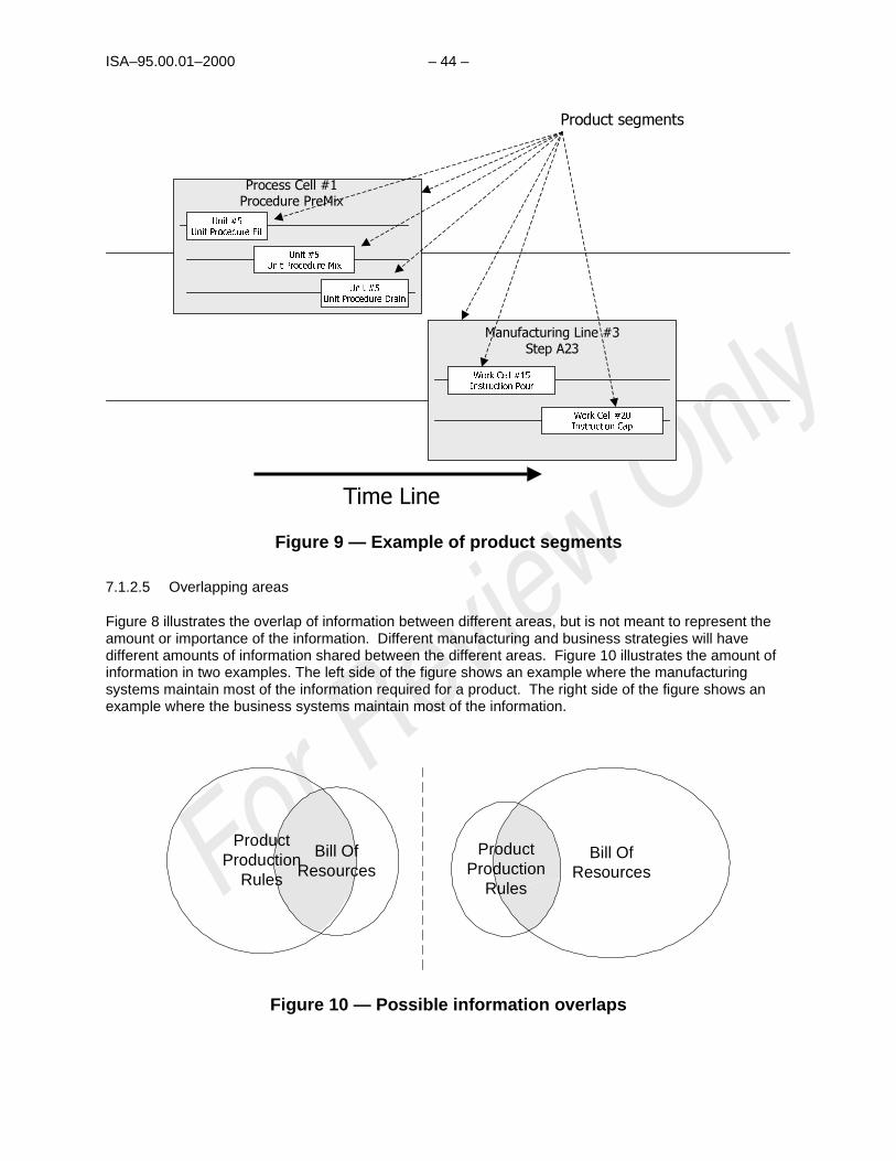
ISA–95.00.01–2000 – 44 –
8QLW���8QLW�3URFHGXUH�)LOO
8QLW���8QLW�3URFHGXUH�0L[
8QLW���8QLW�3URFHGXUH�'UDLQ
:RUN�&HOO����,QVWUXFWLRQ�3RXU
:RUN�&HOO����,QVWUXFWLRQ�&DS
7LPH�/LQH�
3URFHVV�&HOO���3URFHGXUH�3UH0L[
0DQXIDFWXULQJ�/LQH���6WHS�$��
3URGXFW�VHJPHQWV
Figure 9 — Example of product segments
7.1.2.5 Overlapping areas
Figure 8 illustrates the overlap of information between different areas, but is not meant to represent theamount or importance of the information. Different manufacturing and business strategies will havedifferent amounts of information shared between the different areas. Figure 10 illustrates the amount ofinformation in two examples. The left side of the figure shows an example where the manufacturingsystems maintain most of the information required for a product. The right side of the figure shows anexample where the business systems maintain most of the information.
Bill OfResources
ProductProduction
Rules
Bill OfResources
ProductProduction
Rules
Figure 10 — Possible information overlaps

– 45 – ISA–95.00.01–2000
7.1.3 Production information
There are three main areas of information about actual production that have significant overlap. Thesethree areas are production information, inventory information, and the production scheduling information.Figure 11 shows the overlap between the areas of information.
ProductionInventory
Information
ProductionSchedulingInformation
Production history information about actual production of products
ProductionHistory
InformationProduction schedule and performance
Information on all inventoried materialand equipment.
Scheduling information on productionProduction
SegmentInformation
Production Material Information
Figure 11 — Production information
7.1.3.1 Production history information
Production history information is all of the information recorded about production of a product. This maybe called by many names, such as the batch journal, product log, or traveler.
7.1.3.2 Production inventory information
Production inventory information is all of the information about inventoried materials, including the currentstatus of the materials. Typically all consumed and produced materials are maintained in the productioninventory information, and sometimes intermediates are maintained if they are needed for financialevaluation. In some industries this may include energy information.
7.1.3.3 Production scheduling information
The scheduling model contains all of the information about the execution of scheduled production runs.
7.1.3.4 Production segment information
The production segment information is the part of the production history information that containsinformation on the segments of production and is used for scheduling.

ISA–95.00.01–2000 – 46 –
7.1.3.5 Production material information
The production material information is the part of the production history information that containsinformation on material that is used by inventory.
7.1.3.6 Production schedule and performance
Production schedule and performance information is shared among production information, inventoryinformation, and scheduling information. This includes the definition of the raw materials consumed,materials produced, and materials scrapped. It also includes the definition of how long segments ofproduction actually took and how much material was produced and consumed by specific segments ofproduction. This information is generally used to track actual production against production requests andas feedback to the scheduling cycle.
7.1.4 Process segment
Given the previous definitions, a process segment is defined as the collection of capabilities needed for asegment of production, independent of any particular product. This may include material, energy,personnel, or equipment capabilities. The capabilities may specify specific capabilities or the class ofcapability (such as class of equipment) needed for the process segment. Figure 12 illustrates howcapabilities relate to process segments.
a) A manual segment may define the class of materials and class of personnel needed for production
b) A semi-automated segment may define the class of materials, personnel, and equipment needed
c) A non-material segment, such as an equipment setup segment, may define the class of equipmentand personnel used
d) An automated segment may only define the material and equipment classes needed
PersonnelCapability
EquipmentCapability
All material available for production
MaterialCapability
Manual process segments, such as repack
All available personnel capabilities
Semi-automated process segments
Non-material segments, such as equipment setup
All available equipment capabilities
Automatedprocess
segments
Figure 12 — Process segment capabilities

– 47 – ISA–95.00.01–2000
There is a relationship among the collection of process segments, the product segment definitions foreach product, and the segment requirements for any specific production request. This concept isillustrated in Figure 13. A product segment must reference a process segment known to production, anda segment requirement must reference a known product segment of the product being manufactured.
$ ( & $ (&%
3URGXFW6HJPHQW
6HJPHQW5HT�
&ROOHFWLRQ�RISURFHVVVHJPHQWV
3URGXFW�VHJPHQWVIRU�D�VLQJOH�SURGXFW
GHILQLWLRQ��ZLWK�URXWLQJ�H�J��3URGXFW�<<<�
6HJPHQW�UHTXLUHPHQWVIRU�D�VSHFLILF
SURGXFWLRQ�UHTXHVW�H�J��/RW�����RI�3URGXFW�<<<
&
('
$
3DUDPHWHUV(TXLSPHQW
0DWHULDO
3URFHVV6HJPHQW
3HUVRQQHO
3URGXFW�3DUDPHWHUV(TXLSPHQW�6SHFLILFDWLRQV
0DWHULDO�6SHFLILFDWLRQV3HUVRQQHO�6SHFLILFDWLRQV
3URGXFWLRQ�3DUDPHWHUV(TXLSPHQW�5HTXLUHPHQW
0DWHULDO�5HTXLUHPHQW3HUVRQQHO�5HTXLUHPHQW
PXVWUHIHUHQFH
PXVWUHIHUHQFH
Figure 13 — Segment relations
7.2 Object model structure
The object models are depicted using the Unified Modeling Language8 (UML) notational methodology.The diagrams have been kept simple and as a result objects may appear on multiple diagrams.
The general model for allowing extensibility to the information exchange is through the addition ofproperties to the objects. There may be sets of extensions that are business specific; for example, thefood and beverage business may have commonly understood extensions that relate to nutritional contentand caloric content.
Table 2 defines the UML notations used in the object diagrams.
______
8 J.Rumbaugh/I. Jacobson, THE UNIFIED MODELING LANGUAGE REFERENCE MANUAL, © 1999 by Addison Wesley Longman,Inc. Reprinted by permission of Addison Wesley Longman.

ISA–95.00.01–2000 – 48 –
Table 2 — UML notation used
Symbol Definition
PACKAGE
Defines a package, a collection of object models, state models, useclasses, and other UML models. In this document a package is used tospecify an external model, such as a production rule model, or areference to another part of the model.
Class
Attributes : Type
Defines a class of objects, each with the same types of attributes. Eachobject must be uniquely identifiable or enumerable. No operations ormethods are listed for the classes. Attributes with a “ - ” before theirname indicate attributes that are generally optional in any use of theclass.
0..n
1..1
Association Name
Role
Role
An association between elements of a class and elements of another orthe same class. Each association is identified. Can have the expectednumber or range of members of the subclass, when ‘n’ indicates anindeterminate number. For example, 0,n means that zero or moremembers of the subclass may exist.
Is A Type Of
Generalization (arrow points to the super class) shows that an element ofthe class is a specialized type of the super class.
Depends OnDependence (tightly bound relationship between the items) shows thatan element of the class depends on an element of another class.
Is Made Up Of
Aggregation (made up of) shows that an element of the class is made upof elements of other classes.
7.3 Production capability information
The production capability information is the collection of information about all resources for production forselected times. This information corresponds to the overlap of information depicted in Figure 7. This ismade up of information about equipment, material, personnel, and process segments. It describes thenames, terms, statuses, and quantities of which the manufacturing control system has knowledge. Theproduction capability information contains the ‘vocabulary’ for capacity scheduling and maintenanceinformation.
7.3.1 Production capability
Production capability is the collection of available capability, committed capability, and unattainablecapability, as depicted in Figure 14. The production capability is the theoretical maximum capabilityavailable for use in production.
a) Committed capability defines resources that are committed to future production, usually due toexisting schedules and/or materials in production.
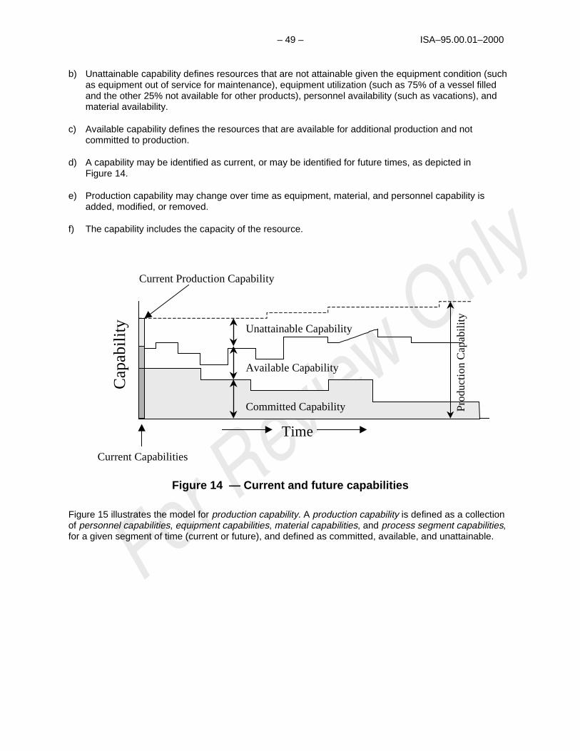
– 49 – ISA–95.00.01–2000
b) Unattainable capability defines resources that are not attainable given the equipment condition (suchas equipment out of service for maintenance), equipment utilization (such as 75% of a vessel filledand the other 25% not available for other products), personnel availability (such as vacations), andmaterial availability.
c) Available capability defines the resources that are available for additional production and notcommitted to production.
d) A capability may be identified as current, or may be identified for future times, as depicted inFigure 14.
e) Production capability may change over time as equipment, material, and personnel capability isadded, modified, or removed.
f) The capability includes the capacity of the resource.
Cap
abili
ty
Prod
ucti
on C
apab
ilit
y
Unattainable Capability
Available Capability
Committed Capability
Time
Current Capabilities
Current Production Capability
Figure 14 — Current and future capabilities
Figure 15 illustrates the model for production capability. A production capability is defined as a collectionof personnel capabilities, equipment capabilities, material capabilities, and process segment capabilities,for a given segment of time (current or future), and defined as committed, available, and unattainable.
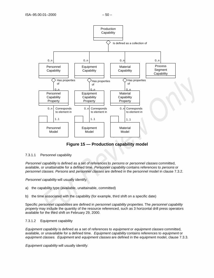
ISA–95.00.01–2000 – 50 –
PersonnelCapability
EquipmentCapability
MaterialCapability
ProcessSegmentCapability
PersonnelModel
EquipmentModel
MaterialModel
ProductionCapability
Correspondsto element in
Is defined as a collection of
0..n0..n0..n0..n
0..n 0..n 0..n
1..11..11..1
PersonnelCapabilityProperty
EquipmentCapabilityProperty
MaterialCapabilityProperty
0..n
Has propertiesof
0..n
Has propertiesof
0..n
Has propertiesof
Correspondsto element in
Correspondsto element in
Figure 15 — Production capability model
7.3.1.1 Personnel capability
Personnel capability is defined as a set of references to persons or personnel classes committed,available, or unattainable for a defined time. Personnel capability contains references to persons orpersonnel classes. Persons and personnel classes are defined in the personnel model in clause 7.3.2.
Personnel capability will usually identify:
a) the capability type (available, unattainable, committed)
b) the time associated with the capability (for example, third shift on a specific date)
Specific personnel capabilities are defined in personnel capability properties. The personnel capabilityproperty may include the quantity of the resource referenced, such as 3 horizontal drill press operatorsavailable for the third shift on February 29, 2000.
7.3.1.2 Equipment capability
Equipment capability is defined as a set of references to equipment or equipment classes committed,available, or unavailable for a defined time. Equipment capability contains references to equipment orequipment classes. Equipment and equipment classes are defined in the equipment model, clause 7.3.3.
Equipment capability will usually identify:

– 51 – ISA–95.00.01–2000
a) the capability type (available, unattainable, committed)
b) the time associated with the capability (for example, third shift on a specific date)
Specific equipment capabilities are defined in equipment capability properties. The equipment capabilityproperties may include the quantity of the resource referenced, such as 3 horizontal drill presses currentlyavailable.
7.3.1.3 Material capability
Material capability is defined as a set of references to material lots or sublots committed, available, orunavailable for a defined time. This includes information that is associated with the functions of materialand energy control (4.0) and product inventory control (7.0). The currently available and committedmaterial capability is the inventory. WIP (work in progress) is a material capability currently under thecontrol of production.
Material capability will usually identify:
a) the capability type (available, unattainable, committed)
b) the time associated with the capability (for example, third shift on a specific date)
Specific material capabilities are defined in material capability properties. The material capabilityproperties may include the quantity of the material referenced, such as 3 sublots in building 3 of materialstarch lot #12345 committed to production for February 29, 2000.
7.3.1.4 Process segment capability
A process segment capability is defined as a logical grouping of personnel resources, equipmentresources, and material that is committed, available, or unavailable for a defined process segment for aspecific time (see Figure 16).
A process segment capability is related to a product segment that can occur during production, as definedin the product information model, clause 7.4. A process segment capability may relate to one or moreproducts.
Process segment capability will usually identify:
a) the capability type (available, unattainable, committed)
b) the time associated with the capability (for example, third shift on a specific date)
Process segment capabilities are made up of:
a) Personnel segment capabilities, which may define specific properties required in personnel segmentcapability properties
b) Equipment segment capabilities, which may define specific properties required in
c) Material segment capabilities, which may define specific properties required in material segmentcapability properties

ISA–95.00.01–2000 – 52 –
Personnel Segment Capability
EquipmentSegment Capability
Material Segment Capability
ProcessSegment Capability
Has propertiesof
Has propertiesof
Has propertiesof
Is defined as a collection of
0..n0..n0..n
0..n0..n0..n
PersonnelModel
EquipmentModel
MaterialModel
Correspondsto element in
0..n 0..n 0..n
1..11..11..1
Personnel Segment CapabilityProperty
Equipment Segment CapabilityProperty
Material Segment CapabilityProperty
Correspondsto element in
Correspondsto element in
ProcessSegment
Corresponds to
Figure 16 — Process segment capability model
7.3.2 Personnel model
The personnel model contains the information about specific personnel, classes of personnel, andqualifications of personnel. Figure 17 illustrates the personnel model.

– 53 – ISA–95.00.01–2000
PersonnelClass Property
PersonProperty
QualificationTest
Specification
PersonnelClass
Hasvalues for
0..n
0..n
0..n
0..n
0..n
Person
QualificationTest
Result
0..n
0..n1..n
Hasproperties
of
Is testedby a
Maps to
Defined by
Records theexecution of
Defines aprocedure forobtaining a
Figure 17 — Personnel model
7.3.2.1 Personnel class
A personnel class is a means to describe a grouping of persons with similar characteristics for purposesof scheduling and planning. Any person may be a member of zero or more personnel classes.
Examples of personnel classes are “cook machine mechanics,” “slicing machine operators,” “cat-crackeroperator,” and “zipper line inspectors.”
7.3.2.2 Personnel class property
Each personnel class may have zero or more recognized properties. Examples of personnel classproperties for the personnel class “operators” may be “class 1 certified,” “class 2 certified,” “night shift,”and “exposure hours.” Production requests may specify required personnel class property requirementsfor a product segment.
7.3.2.3 Person
A person represents a specifically identified individual. A person may be a member of zero or morepersonnel classes.
a) Person will include a unique identification of the individual
7.3.2.4 Person property
Each person may have zero or more person properties. These specify the current property values of theperson for the associated personnel property. For example: a person property may be “night shift” and itsvalue would be “available," and a person property may be “exposure hours available” and its value wouldbe “4.”
Person properties may include the current availability of a person and other current information, such aslocation and assigned activity, and the unit of measure of the current information.

ISA–95.00.01–2000 – 54 –
7.3.2.5 Qualification test specification
A qualification test specification may be associated with a personnel class property or person property.This is typically used where a qualification test is required to ensure that a person has the correct trainingand/or experience for specific operations. A qualification test specification may test for one or moreproperties.
A qualification test specification will usually include:
a) an identification of the test
b) a version of the test
c) a description of the test
7.3.2.6 Qualification test result
A qualification test result records the results from a qualification test for a specific person.
A qualification test result will usually include:
a) the date of the test
b) the result of the test (passed, failed)
c) the expiration date of the qualification
7.3.3 Equipment model
The equipment model contains the information about specific equipment, the classes of equipment,equipment capability tests, and maintenance information associated with equipment. Figure 18 illustratesthe equipment model.

– 55 – ISA–95.00.01–2000
MaintenanceRequest
MaintenanceRequest
MaintenanceWork Order
MaintenanceWork Order
MaintenanceResponse
MaintenanceResponse
May be generated for0..n
1..1
1..1
1..1
EquipmentClass Property
EquipmentClass Property
EquipmentProperty
EquipmentProperty
EquipmentCapability TestSpecification
EquipmentCapability TestSpecification
EquipmentClass
EquipmentClass
Hasvalues for
0..n
0..n
0..n
0..n
0..n
EquipmentEquipment
EquipmentCapability Test
Result
EquipmentCapability Test
Result
0..n
0..n1..n
Hasproperties
of
Is testedby a
Maps to
Defined by
Records theexecution of
0..n
0..n May result in
0..1
May be made up of Is against
Is madeagainst
0..n
0..n
Defines aprocedure forobtaining a
Figure 18 — Equipment model
7.3.3.1 Equipment class
An equipment class is a means to describe a grouping of equipment with similar characteristics forpurposes of scheduling and planning. Any piece of equipment may be a member of zero or moreequipment classes. Examples of equipment classes are “reactor unit,” “bottling line,” and “horizontal drillpress.”
7.3.3.2 Equipment class property
Each equipment class may have zero or more recognized properties. Examples of equipment classproperties for the equipment class “reactor unit” may be “lining material,” “BTU extraction rate,” and“volume.” Production requests may specify required equipment property requirements for a productsegment.
7.3.3.3 Equipment
Equipment represents the elements of the equipment hierarchy model defined in clause 4.2. Equipmentmay be definitions of sites, areas, production units, production lines, work cells, process cells, or units.
Equipment may be made up of other equipment, as defined in the equipment hierarchy model. Forexample, a production line may be made up of work cells.
Examples of equipment are “reactor unit #1,” “bottling line #1,” and “horizontal drill press #4.”

ISA–95.00.01–2000 – 56 –
7.3.3.4 Equipment property
An equipment may have zero or more equipment properties. These specify the current property values ofthe equipment for the associated equipment class property. Equipment properties may include a unit ofmeasure.
For example, an equipment class property may be “volume” and its value would be “50000” with a unit ofmeasure of “liters,” an equipment property may be “lining material” and its value would be “glass.”
Examples of equipment properties are:
a) the current availability of equipment
b) other current information, such as when calibration is needed
c) maintenance status
d) the current state of the equipment
e) performance values
7.3.3.5 Equipment capability test specification
An equipment capability test specification may be associated with an equipment property. This istypically used where a test is required to ensure that the equipment has the rated capability. Anequipment capability test specification may test for one or more equipment properties.
An equipment capability test specification will usually include:
a) an identification of the test
b) a version of the test
c) a description of the test
7.3.3.6 Equipment capability test result
An equipment capability test result records the results from a qualification test for a specific piece ofequipment.
An equipment capability test result will usually include:
a) the date of the test
b) the result of the test (passed-failed or quantitative result)
c) the expiration date of the test
7.3.3.7 Maintenance information
The overlap of information between manufacturing control and maintenance is in the equipment area.This is represented as maintenance requests, maintenance responses, and work orders associated tospecific equipment.

– 57 – ISA–95.00.01–2000
A maintenance request is made against specific equipment. There may be many outstandingmaintenance requests against a piece of equipment. A maintenance request may result in a maintenancework order against the equipment. Zero or more maintenance work orders may be generated from amaintenance request. A maintenance response is made against a maintenance work order.
Maintenance requests will usually include:
a) who made the request
b) the date and time of the request
c) the needed data and time of resolution
d) the equipment associated with the request
e) a description of the request
f) a priority
Maintenance work orders will usually include:
a) the associated person or personnel class assigned
b) the assigned priority of the work order
c) the status of the work order (for example, pending, in process)
Maintenance responses will usually include:
a) the date and time of the response
b) who responded to the work order
c) a description of the response
d) the result of the work order
7.3.4 Material model
The material model defines the actual materials, material definitions, and information about classes ofmaterial definitions. Material information includes the inventory of raw, finished, and intermediatematerials. The current material information is contained in the material lot and material sublot information.Material classes are defined to organize materials. Figure 19 illustrates the material model.

ISA–95.00.01–2000 – 58 –
MaterialSublot
May be made upof sublots
0..n
0..n
0..n
MaterialDefinitionProperty
Material LotProperty
QA TestSpecification
MaterialDefinition
Hasvalues for
0..n
0..n
0..n
0..n
0..n
Material Lot
QA TestResult
1..1
0..n1..n
Hasproperties
of
Is testedby a
Maps to
Defined by
Records theexecution of
Made up of
MaterialClass
Property
MaterialClass
0..n
Hasproperties
of
0..n
Definesa grouping
Is associatedwith a
Maymap to
Defines aprocedure forobtaining a
Figure 19 — Material model
7.3.4.1 Material definition
A material definition is a means to describe goods with similar characteristics for purposes of schedulingand planning. Examples of these may be “city water,” “HCl,” and “grade B aluminum.” The materials maybe identified as raw, intermediate, or final and may have other state information, such as availability ofsafety information.
Any material lot is defined by one material definition.
Material definitions may also be related to a production request. The same material may have differentdefinitions for different production requests, depending on specific customer requirements.
7.3.4.2 Material definition property
A material definition may be further characterized through zero or more material definition properties.Examples of material definition property include density, pH factor, or material strength. These define thenominal or standard values for the material.
7.3.4.3 Material class
A material class is ameans of defining groupings material definitions for use in production scheduling orprocessing. An example of a material class is "sweetener," with members of "fructose," "corn syrup," and"sugar cane syrup." Another example of a material class is "water," with members of "city water,""recycled water," and "spring water."
A material definition may belong to zero or more material classes.
7.3.4.4 Material class property
A material class may be further characterized through zero or more material class properties. Examplesof material class properties include density, pH factor, and material strength. The material class propertiesusually define the nominal, or standard, values for the material. A material property does not have tomatch a material class property.

– 59 – ISA–95.00.01–2000
7.3.4.5 Material lot
A material lot object uniquely identifies a specific amount of material, countable or weighable. Thisdescribes the actual total quantity or amount of material available, its current state, and its specificproperty values.
Materials may be made up of other materials but that association is not described in this model.
A material lot may include:
a) a unique identification of the lot
b) the amount of material (count or weight)
c) the unit of measure of the material (for example, parts, kg, tons)
d) a location for the material
e) any committed status of the lot
Material lots and material sublots may be used for traceability when they contain unique identifications.
7.3.4.6 Material lot property
Each material may have unique values for zero or more material lot properties, such as a specific pHvalue for the specific lot of material, or a specific density for the lot of material.
7.3.4.7 Material sublot
A material lot may be stored as a separate identifiable quantity. Each separate identifiable quantity of thematerial is identified in a material sublot object. All material sublots must contain the same material lot, sothey use the material lot element’s property values. A material sublot may be just a single item.
Each material sublot also contains the location of the sublot and the quantity or amount of materialavailable in the sublot.
Material sublots may contain other sublots. For example, a sublot may be a pallet, each box on the palletmay also be a sublot, and each material blister pack in the box may also be a sublot.
A material sublot may include:
a) a unique identification of the sublot
b) the packing mode of the material
c) the unit of measure of the material (for example, parts, kg, tons)
d) any committed status of the sublot

ISA–95.00.01–2000 – 60 –
7.3.4.8 QA test specification
A QA test specification may be associated with a material class property. This is typically used where atest is required to ensure that the material has the required property value. A QA test specification mayidentify a test for one or more material class properties. Not all properties need to have a defined QAtest specification.
QA test specifications may also be related to a production request. The same material may have differentspecifications for different production requests, depending on specific customer requirements.
A QA test specification will usually include:
a) an identification of the test
b) a version of the test
c) a description of the test
7.3.4.9 QA test results
A QA test result records the results from a QA test for a specific piece of material lot. QA test results willusually have the following characteristics:
a) They are related to a material lot
b) They may be related to a production request
c) They may be associated with a specific production response
d) They may be related to a specific process segment
e) They generally include a pass/fail status of the test
f) They may include quantitative information of the tests
g) The result may be the granting or refusing of an in-process or finished goods waiver request
h) They may be related to a product characteristic
QA test results may be associated with a specific production response.
7.3.5 Process Segment Model
The process segment model contains information about the commonly defined process segments. Figure20 illustrates the process segment model.

– 61 – ISA–95.00.01–2000
Personnel SegmentSpecification
Equipment SegmentSpecification
Material Segment Specification
ProcessSegment Parameter
ProcessSegment
Has propertiesof
Has propertiesof
Has propertiesof
Is defined as a collection of
0..n0..n0..n0..n
0..n0..n0..n
May bemade up of
0..n
PersonnelModel
EquipmentModel
MaterialModel
Correspondsto element in
0..n 0..n 0..n
1..11..11..1
Personnel SegmentSpecification
Property
Equipment Segment Specification
Property
Material Segment Specification
Property
Correspondsto element in
Correspondsto element in
Figure 20 — Process segment model
7.3.5.1 Process segment
A process segment is a logical grouping of personnel resources, equipment resources, and materialrequired to carry out a production step. Process segment usually defines the needed classes ofpersonnel, equipment, and material, but it may define specific resources, such as specific equipmentneeded. Process segment usually defines the quantity of the resource needed.
A process segment is related to a product segment that can occur during production, as defined in theproduct information model in clause 7.4. A process segment may relate to one or more products.
Process segment will usually identify:
a) the time duration associated with the capability (for example, 5 hours, or 5 hours/100 kg),
b) and may include constraint rules associated with ordering or sequencing of segments
A process segment may be made up of other process segments, in a hierarchy of definitions. Figure 20illustrates the elements of a process segment.
Process segments may contain specifications of specific resources required by the process segment.Process segments may contain parameters that can be defined in specific production requests.
ISA–95.00.01–2000 – 62 –
7.3.5.2 Process segment parameter
Process segment parameters define specific parameters required for the segment. Examples ofparameters are product colors, quality requirements, assembly options, and packaging options.
7.3.5.3 Personnel segment specification
Personnel segment specifications define what personnel resources are required for the process segment,such as three lathe machine operators, or a certified inspector. Specific properties that are required arespecified in personnel segment specification properties.
7.3.5.4 Equipment segment specification
Equipment segment specifications define what equipment resources are required for the processsegment, such as three lathe operators, or a certified test chamber. Specific properties that are requiredare specified in equipment segment specification properties.
7.3.5.5 Material segment specification
Material segment specifications define what material resources are required for the process segment,such as distilled water or HCl. Specific properties that are required are specified in material segmentspecification properties.
7.4 Product definition information
The product definition information is information shared between production rules, bill of material, and billof resources. These three external models are represented by packages in Figure 21; their definitionsare outside the scope of this document. The model in this clause defines the information shown in theshaded areas of Figure 8.
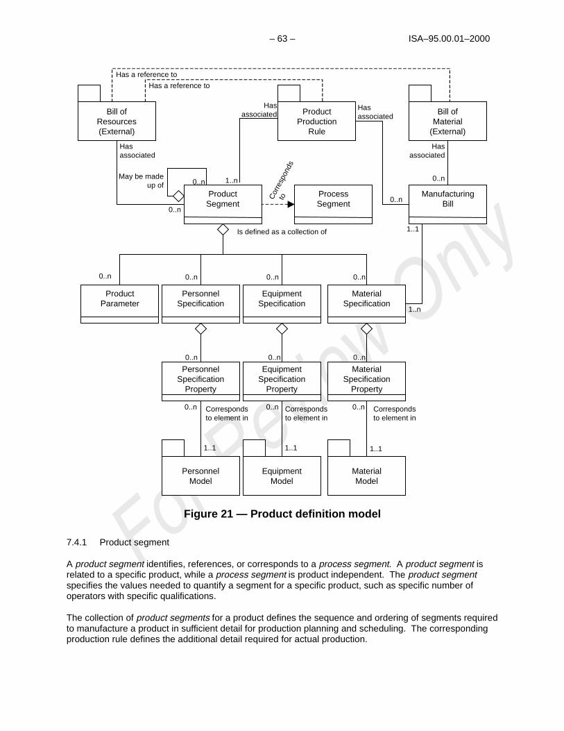
– 63 – ISA–95.00.01–2000
PersonnelSpecification
EquipmentSpecification
MaterialSpecification
ProductParameter
PersonnelModel
EquipmentModel
MaterialModel
ProductSegment
Correspondsto element in
Correspondsto element in
Correspondsto element in
Is defined as a collection of
0..n 0..n0..n0..n
0..n 0..n 0..n
1..11..11..1
Bill ofResources(External)
Bill ofMaterial
(External)
ProductProduction
Rule
Hasassociated
Hasassociated
Hasassociated
Hasassociated
0..n
0..n 1..n
1..n
0..n
1..1
May be madeup of
PersonnelSpecification
Property
EquipmentSpecification
Property
MaterialSpecification
Property
0..n 0..n 0..n
ManufacturingBill0..n
Has a reference to
Has a reference to
ProcessSegment C
orre
spon
ds
to
Figure 21 — Product definition model
7.4.1 Product segment
A product segment identifies, references, or corresponds to a process segment. A product segment isrelated to a specific product, while a process segment is product independent. The product segmentspecifies the values needed to quantify a segment for a specific product, such as specific number ofoperators with specific qualifications.
The collection of product segments for a product defines the sequence and ordering of segments requiredto manufacture a product in sufficient detail for production planning and scheduling. The correspondingproduction rule defines the additional detail required for actual production.

ISA–95.00.01–2000 – 64 –
A product segment may use zero or more resources, which may correspond to an equipmentspecification, a personnel specification or a material specification. A product segment may haveparameter values for parameters specified in the corresponding process segment.
7.4.1.1 Product parameter
The production rule definition is outside the scope of this document, but a production rule will have anassociated set of zero or more product parameters per product segment for each product defined. Theproduct parameters define the names and types of the values that may be sent to the control system toparameterize the product. Examples of product parameter specifications are “pH of 3.5,” “pressure limitof 35 psi,” and “flange color = orange.” Product parameters may include:
a) An identification of the parameter
b) A default value for the parameter
c) The units of measure of the parameter value
d) Possible ranges of the parameter value--may include alarm or quality ranges
e) Tolerances for acceptable parameter values
7.4.1.2 Personnel specification
A personnel specification identifies, references, or corresponds to a personnel capability and usuallyspecifies personnel class but may sometimes specify a person. This identifies the specific personnelcapability that is associated with the identified product segment. A personnel specification may include:
a) An identification of the personnel capability needed
b) The quantity of the personnel capability needed
c) The unit of measure of the quantity
Specific elements associated with a personnel specification may be included in one or more personnelspecification properties. Examples of personnel specification properties are training level required,specific skill required, and exposure availability.
7.4.1.3 Equipment specification
An equipment specification identifies, references, or corresponds to an equipment capability and mayspecify either an equipment class or a piece of equipment. This identifies the specific equipmentcapability that is associated with the identified product segment. An equipment specification may include:
a) An identification of the equipment capability needed either as the equipment class needed or specificequipment
b) The quantity of the equipment capability needed
c) The unit of measure of the quantity
d) The production performance target

– 65 – ISA–95.00.01–2000
Specific elements associated with an equipment specification may be included in one or more equipmentspecification properties. Examples of equipment specification properties are material of construction,maximum material capacity, and minimum heat extraction amount.
7.4.1.4 Material specification
A material specification identifies or corresponds to a material capability and usually specifies a materialor a material class. This identifies the specific material specification that is associated with the identifiedproduct segment. A material specification may include :
a) An identification of the material capability needed
b) The quantity of the material capability needed
c) The unit of measure of the quantity
d) Alternate materials or material classes that could be used in place of the primary material specified
e) The production performance target
Specific elements associated with a material specification may be included in one or more materialspecification properties. Examples of material specification properties are color range, density tolerance,and maximum scrap content.
7.4.2 Manufacturing bill
A manufacturing bill identifies a material or material class that is needed for production of the product.
The manufacturing bill includes all uses of the material in production of the product, while the productsegment’s material specification defines just the amount used in a segment of production.
For example, a manufacturing bill may identify 55 Type C left-threaded screws, where 20 are used in oneproduct segment, 20 in another product segment, and 15 in a third product segment.
7.5 Production information
Production information is defined in two models, shown in Figure 22 and Figure 23. These correspond torequests for production and responses to the requests.
A request for production is defined in a production schedule.
7.5.1 Production schedule
The production schedule shown in Figure 22 defines the shaded information shown in Figure 11. Aproduction schedule is made up of one or more production requests.

ISA–95.00.01–2000 – 66 –
PersonnelRequirement
PersonnelRequirement
EquipmentRequirementEquipment
RequirementMaterial Produced
RequirementMaterial Produced
Requirement
PersonnelModel
PersonnelModel
EquipmentModel
EquipmentModel
MaterialModel
MaterialModel
Corresponds to element in
Corresponds to element in
Corresponds to element in
May contain
0..n 0..n0..n0..n
1..n
PersonnelRequirement
Property
PersonnelRequirement
Property
EquipmentRequirement
Property
EquipmentRequirement
Property
Material ProducedRequirement
Property
Material ProducedRequirement
Property
1..n 1..n 1..n
ProductionSchedule
ProductionSchedule
ProductParameter
ProductParameter
ProcessParameterProcess
Parameter
Material ConsumedRequirement
Material ConsumedRequirement
Corresponds to element in
0..n
Material ConsumedRequirement
Property
Material ConsumedRequirement
Property
1..n
ConsumableExpected
ConsumableExpected
0..n
ConsumableExpectedProperty
ConsumableExpectedProperty
1..n
SegmentRequirement
SegmentRequirement
1..n
Is made up of
Is made up of
Is associatedto either
ProcessSegmentProcessSegment
ProductProduction
Rule
ProductProduction
Rule
RequestedSegmentResponse
RequestedSegmentResponse
Correspondsto a
Correspondsto a
ProductionParameterProductionParameter
ProductionRequest
ProductionRequest
0..n
Figure 22 — Production schedule model
7.5.2 Production request
A production request defines a request for production for a single product identified by a production rule.A production request contains the information required by manufacturing to fulfill scheduled production.This may be a subset of the business production order information, or it may contain additionalinformation not normally used by the business system.
A production request might identify or reference the associated production rule. A production requestmust contain at least one segment requirement, even if it spans all production of the product. If notuniquely defined by the production rule, then a segment requirement will contain at least one materialproduced requirement with the identification, quantity, and units of measure of the material to beproduced.
A production request may also include:
a) When to start production, typically used if a scheduling system controls the schedule

– 67 – ISA–95.00.01–2000
b) When the production is to be finished, typically used if the manufacturing system controls its internalschedule to meet deadlines
c) The priority of the request, typically used if exact ordering of production is not externally scheduled
d) A pack out schedule
e) A pre-assigned lot identification for the produced material
A production request may be reported on by one or more production responses. In some situations, thematerial identification, production rule identification, and material quantity may be all that is needed for themanufacturing. Other situations may require additional information. The additional information may bedescribed in the production parameters, personnel requirements, equipment requirements, and materialrequirements.
7.5.2.1 Segment requirement
A production request is made up of one or more segment requirements. Each segment requirement mustcorrespond to, or reference, an identified process segment. The segment requirement identifies orreferences the segment capability to which the associated personnel, equipment, materials, andproduction parameters correspond.
The personnel requirement property, equipment requirement property and product parameter must alignwith the personnel property, equipment property, and product parameters sent as part of a productionrequest. If the scheduling function sends information that is not understood by the receiving controlfunction, then that information cannot be used within the control function. Likewise the schedulingfunction must be able to determine what information can be accepted by the control function.
7.5.2.2 Personnel requirement
A personnel requirement and the associated personnel requirement property elements refer to thenumber, type, duration, and scheduling of specific certifications and job classifications needed to supportthe current production request. Examples of job classification types include "mechanics," "operators,""health & protection," and "inspectors."
For example, there may be a requirement for one operator with a specified level of certification availabletwo hours after production starts. There would be one personnel requirement for the requirement for theoperator and two personnel requirement properties, one for the certification level and one for the timerequirement.
A personnel requirement typically includes:
a) The identification of the personnel capability needed, such as “milling machine operator”
b) The quantity of personnel capability needed
Specific elements associated with each personnel requirement may be included in one or more personnelrequirement properties.
Examples of personnel requirement property elements are training and certification, specific skill, physicallocation, seniority level, exposure level, training certification, security level, experience level, physicalrequirements, and overtime limitations and restrictions.
7.5.2.3 Equipment requirement

ISA–95.00.01–2000 – 68 –
The production request may include one or more requirements for, or constraints upon, the equipmentthat the facility will use in the production process for the scheduled item. Requirements can be as genericas materials of construction, or as specific as a particular piece of equipment. Each of theserequirements is an instance of the equipment requirement class.
Each equipment requirement identifies a general class of equipment (such as “reactor vessels”), aspecific class of equipment (such as “isothermal reactors”), or a specific piece or set of equipment (suchas “isothermal reactor #7”). The specific requirements on the equipment, or equipment class are definedin equipment requirement property objects.
An equipment requirement typically includes:
a) The identification of the equipment capability needed, such as “milling machine”
b) The quantity of equipment capability needed
c) The product segment the equipment requirement is needed in, such as “first-step rough shaping”
Specific elements associated with each equipment requirement may be included in one or moreequipment requirement properties.
Examples of equipment requirement properties are material of construction and minimum equipmentcapacity.
7.5.2.4 Material produced requirement
A material produced requirement is an identification of a material to be produced from the productionrequest. A material produced requirement may include:
a) The total quantity of the material to be produced and unit of measure, such as 5000 lbs
b) An acceptable range for the quantity of material
Specific elements associated with each material produced requirement may be included in one or morematerial produced requirement properties.
Examples of material produced requirement properties are:
a) fat content
b) octane rating
c) delivery locations
d) material lot identification (such as “starch lot #45663”) to be assigned to the material
e) identification of sublots
7.5.2.5 Material consumed requirement
A material consumed requirement is an identification of a material to be used in the production request. Amaterial consumed requirement may include:
a) The total quantity of the material to be used and unit of measure, such as 5000 lbs

– 69 – ISA–95.00.01–2000
b) An acceptable range for the quantity of material
Specific elements associated with each material consumed requirement may be included in one or morematerial consumed requirement properties.
Examples of material produced requirement properties may include:
a) Material lot (such as “starch lot #45663”)
b) A list of possible material lots that can be used in production, where the production system oroperators may select the lot from the list, as described in clause 7.3.4.5
c) A material definition, such as “starch,” where the actual lot of material is not specified
d) A material class, such as "starch alternates," so that any material lot of that class can be used forproduction
7.5.2.6 Consumable expected
Consumable expected includes resources that are not normally included in bills of material or are notindividually accounted for in specific production requests. Depending on the industry these may includewater, catalysts, common chemicals, and utilities, such as electricity and steam. These items will oftenresult in direct charges that will usually be considered in costing the product segment. Consumables areoften materials that do have an inventory balance.
In some industries consumable expected are not used and the information is included in materialconsumed requirement.
Consumables do not have lot identifications. Consumables with lot identifications are typically treated asmaterial consumed requirements.
Consumable expected usually include the following information:
a) The identification of the resource expected to be consumed
b) The total quantity of the resource expected to be consumed and the unit of measure of the quantity
Specific elements associated with each consumable expected may be included in one or moreconsumable expected properties.
Examples of consumable expected properties may include:
a) A unique identification of the consumable, such as “river water 01-01-2001”
b) A definition of the consumable, such as “rubber gloves” or "cotton balls"
7.5.2.7 Production parameter
A production parameter is information contained in the enterprise system that is required by the operationsystem for correct production.
Examples of production parameters are:
a) quality limits

ISA–95.00.01–2000 – 70 –
b) setpoints
c) targets
d) specific customer requirements (such as "purity = 99.95%")
e) final disposition of the produced product
f) transportation information
g) other information not directly related to control (such as a customer order number required forlabeling or language for labels)
A production parameter may include:
a) An identification of the parameter that matches the product parameter of the product’s productionrule, such as “target acidity”
b) A value for the parameter, such as 3.4
c) The type of the parameter, such as “pH”
d) A set of limits that apply to any change to the value, such as quality limits and safety limits
Production parameters may be either product parameters that define some characteristics of the product(such as paint color), or process parameters that define some characteristics of the production process(such as bake time).
7.5.2.8 Requested segment response
A requested segment response is the definition of the information that must be sent back as a result ofthe production request. This information is of the same form as a segment response, but withoutcontaining actual values.
A requested segment response may include required information, which defines information that must bereported on from production, such as the actual amount of material consumed.
A requested segment response may include optional information, which defines information that may bereported on from production, such as operator-entered comments.
7.5.3 Production performance
The performance of the requested manufacturing requests is the production performance. Productionperformance is a collection of production responses (see Figure 23).
7.5.4 Production response
Production responses are the responses from manufacturing that are associated with a productionrequest. There may be one or more production responses for a single production request if theproduction facility needs to split the production request into smaller elements of work. For example, asingle production request for the production of “200 gears” may be reported on by ten productionresponse objects of “20 gears” each because of manufacturing restrictions.
A production result may include the status of the request, such as the percentage complete, a finishedstatus, or an aborted status.

– 71 – ISA–95.00.01–2000
PersonnelActual
PersonnelActual
EquipmentActual
EquipmentActual
Material ProducedActual
Material ProducedActual
ProductionData
ProductionData
PersonnelModel
PersonnelModel
EquipmentModel
EquipmentModel
MaterialModel
MaterialModel
Corresponds to element in
Corresponds to element in
Corresponds to element in
May contain
0..n 0..n0..n0..n
1..n
PersonnelActual
Property
PersonnelActual
Property
EquipmentActual
Property
EquipmentActual
Property
Material ProducedActual
Property
Material ProducedActual
Property
1..n 1..n 1..n
ProductionPerformanceProduction
Performance
ProductionResponseProductionResponse
Material ConsumedActual
Material ConsumedActual
Corresponds to element in
0..n
Material ConsumedActual
Property
Material ConsumedActual
Property
1..n
ConsumableActual
ConsumableActual
0..n
ConsumableActual
Property
ConsumableActual
Property
1..n
SegmentResponseSegmentResponse
1..n
Is made up of
Is made up of
ProcessSegmentProcessSegment
Correspondsto a
Figure 23 — Production performance model
Production responses contain the items reported back to the business system, at the end of production orduring production. The business system may need to know intermediate production response statuses,rather than waiting for the final production response status, because of cost accounting of materialproduced or intermediate materials.
7.5.4.1 Segment response
The production response for a specific segment of production is defined as a segment response. Asegment response may be made up of zero or more sets of information on production data, personnelactual, equipment actual, utilities actual, materials consumed actual, materials produced actual, andconsumables actual. A segment response may include:
a) An identification of the associated process segment
b) The actual starting and stopping time of the segment
ISA–95.00.01–2000 – 72 –
c) The duration of the segment
The response actuals may contain attributes that define if the response was required or optional.
7.5.4.2 Production data
Production data is information related to the actual products made. Examples of production data are:
a) A customer order number associated with the production request
b) Specific commercial notes from operations related to the customer order, such as “order complete,”“order incomplete,” or an anticipated completion date and time
c) Quality information
d) Certification of analysis
e) Procedural deviations, such as an identification of an event defined in another system and alarminformation
f) Process behavior, such as temperature profiles
g) Operator behavior, such as interventions, actions, and comments
7.5.4.3 Personnel actual
The personnel actuals in a production response identifies a personnel capability used during a specifiedproduct segment. Production functions often require people as a resource to carry out tasks. Personnelactuals may include the following information:
a) The identification of each resource used, usually identifying a specific personnel capability orpersonnel class, such as "end point transmission assembly operators," or personnel IDs such as“Jean Smith” or “SS# 999-123-4567”
Specific information about personnel actuals is defined in personnel actual properties. Examples ofpersonnel actual properties are:
a) The actual duration of use of the personnel during the product segment, such as “2 hours”; thisinformation is often needed for actual costing analysis
b) Actual monitored exposure times by the personnel during the product segment
c) The location of the personnel after use in the product segment, such as “area 51”; this information isoften used for short-term scheduling of personnel resources
7.5.4.4 Equipment actual
The equipment actual in a production response identifies an equipment capability used during a specifiedproduct segment. Production functions often require equipment as a resource to carry out tasks.Equipment actual may include the following information:
a) The identification of the equipment used, usually identifying a specific piece of equipment
Specific information about equipment actuals is defined in equipment actual properties. Examples ofequipment actual properties are:
– 73 – ISA–95.00.01–2000
a) The actual duration of use of the equipment during the product segment; this information is oftenneeded for actual costing analysis
b) The equipment condition, after use in the product segment, such as a status of available, out-of-service, or cleaning; this information is often used for short-term scheduling of equipment resources
c) The equipment setup procedures used for the product segment; this information is often needed foractual costing analysis and scheduling feedback
d) Other equipment attributes, such as percentage of available capability used
7.5.4.5 Material produced actual
The material produced actual in a production response identifies the material produced during a definedproduct segment. The material may be the final product, an intermediate product that must be identifiedfor costing or scheduling purposes, or a scrapped product or material. Material produced actuals mayinclude the following information:
a) The identification of the material produced, usually identifying the material; examples include “resin-89-B”, “motherboard MP667a”
b) The quantity of the material produced and the unit of measure of the quantity produced, such as “500parts,” “50000 liters”
Specific information about material produced actuals is defined in material produced actual properties.Examples of material produced actual properties are:
a) An identification of the material lot or material sublot produced
b) Type of material, such as final, intermediate, or co-product
7.5.4.6 Material consumed actual
The material consumed actual in a production response identifies the material used during a specifiedproduct segment. This material may be identified in the bill of material and may be a raw material orpurchased material. Material consumed usually includes the following information:
a) The identification of the material consumed
b) The quantity of the material consumed and the unit of measure of the quantity
Specific information about material consumed actuals is defined in material consumed actual properties.Examples of material consumed actual properties are:
a) The material lot or material sublot consumed
b) Comments about the use from operations

ISA–95.00.01–2000 – 74 –
7.5.4.7 Consumable actual
Consumable actuals include resources that are not normally included in bills of material or are notindividually accounted for in specific production requests. These include water, catalysts, commonchemicals, and utilities, such as electricity and steam. These items will often result in direct charges thatwill usually be considered in costing the product segment. Consumables are often materials that do havean inventory balance.
Consumable actuals usually include the following information:
a) The identification of the resource consumed
b) The quantity of the resource consumed and the unit of measure of the quantity
c) Specific information about consumable actuals is defined in consumable actual properties
7.6 Model cross reference
Figure 24 provides an informative illustration of how the object models inter-relate. The productioninformation defines what was made and what was used. Its elements correspond to information inproduction scheduling that defined what to make and what to use. The production scheduling elementscorrespond to information in the product definition that defines what must be specified to make a product.The product definition elements correspond to information in the process segment definitions that definewhat can be done with the production resources.
The slanted rectangles in Figure 24 represent any of the resources (personnel, equipment, or material) orproperties.

– 75 –IS
A–95.00.01–2000
ProductionPerformance
ProductionResponse
SegmentResponse
Correspondsto a
ResourceActual
Property
ResourceActual
ProductionRequest
SegmentRequirement
ResourceRequirement
Property
ResourceRequirement
ProductionRule
ProductSegment
ResourceSpecification
Property
ResourceSpecification
ProcessSegmentCapability
ResourceSegmentCapabilityProperty
ResourceSegmentCapability
Correspondsto a
Correspondsto a
Correspondsto a
ProductionInformation
What wasmade & used
ProductionSchedulingWhat is it to bemade & used
ProductDefinition
What must be definedto make a product
ProcessCapability
What can be donewith the resources
Correspondsto a
Correspondsto a
Correspondsto a
Correspondsto a
Correspondsto a
Correspondsto a
ProductionSchedule
ProductionCapability
ResourceCapabilityProperty
ResourceCapability
Correspondsto a
Correspondsto a
ProductionCapabilityWhat resources
are availableFig
ure 24 —
Object m
odel inter-relations
Table 3 provides a cross-reference betw
een the elements of the inform
ation flows in the data flow
model
and the corresponding clause describing the object model.

ISA–95.00.01 – 76 –
Table 3 — Model cross reference
Data Flow ModelInformation
From Function To Function Object Model clause
6.2.1 Schedule Production scheduling (2.0) Production control (3.0) 7.5.1 and 7.5.2
6.2.2 Production fromplan
Production control (3.0) Production scheduling (2.0) 7.5.3 and 7.5.4
6.2.3 Productioncapability
Production control (3.0) Production scheduling (2.0) 7.3
6.2.4 Material and energyorder requirements
Production control (3.0) Defined in terms of theMaterial Model, 7.3.4
6.2.5 Incoming orderconfirmation
Material and energy control(4.0)
Procurement (5.0) Defined in terms of theMaterial Model, 7.3.4
6.2.6 Long-term materialand energy requirements
Production scheduling (2.0) Material and energy control(4.0)
Defined in terms of theMaterial Model, 7.3.4
6.2.7 Short-term materialand energy requirements
Production control (3.0) Material and energy control(4.0)
Defined in terms of theMaterial Model, 7.3.4
6.2.8 Material and energyinventory
Material and energy control(4.0)
Production control (3.0) 7.3.4
6.2.9 Production costobjectives
Product cost accounting(8.0)
Production control (3.0) 7.4
6.2.10 Productionperformance and cots
Production control (3.0) Product cost accounting(8.0)
7.5.3 and 7.5.4
6.2.11 Incoming materialand energy receipt
Material and energy control(4.0)
Product inventory control(7.0)
<Not detailed in objectmodel>
6.2.12 Quality assuranceresults
Quality assurance (6.0) Production control (3.0) 7.3.4.9 and 7.5.4
Marketing and sales Quality assurance (6.0)6.2.13 Standards andcustomer requirements
Quality assurance (6.0) Production control (3.0)
7.3 and 7.5.2
6.2.14 Product andprocess requirements
Research, development,and engineering
Quality assurance (6.0) 7.4
6.2.15 Finished goodswaiver
FunctionsOrder processing (1.0)
Quality assurance (6.0) <Not detailed in objectmodel>Typically unstructuredinformation handled on anad-hoc basis
6.2.16 In-process waiverrequest
Production control (3.0) Quality assurance (6.0) Defined in terms of theMaterial Model, 7.3.4
6.2.17 Finished goodsinventory
Product inventory control(7.0)
Production scheduling (2.0) 7.3.4 and 7.5.4
6.2.18 Process data Production control (3.0) Quality assurance (6.0) 7.5.3 and 7.5.4
6.2.19 Pack out schedule Production scheduling (2.0) Product inventory control(7.0)
7.5.2
6.2.20 Product andprocess know-how
Research, development,and engineering
Production control (3.0) 7.4

– 77 – ISA–95.00.01–2000
Table 3 (continued)
Data Flow ModelInformation
From Function To Function Object Model clause
6.2.21 Product andprocess informationrequest
Production control (3.0) Research, development,and engineering
<Not detailed in objectmodel>
6.2.22 Maintenancerequests
Production control (3.0) Maintenance management(10.0)
7.3.3
6.2.23 Maintenanceresponses
Maintenance management(10.0)
Production control (3.0) 7.3.3
6.2.24 Maintenancestandards and methods
Production control (3.0) Maintenance management(10.0)
<Not detailed in objectmodel>
6.2.25 Maintenancetechnical feedback
Maintenance management(10.0)
Production control (3.0) 7.1.1 and 7.3
6.2.26 Product andprocess technical feedback
Production control (3.0) Research, development,and engineering
<Not detailed in objectmodel>
6.2.27 Maintenancepurchase orderrequirements
Maintenance management(10.0)
Procurement (5.0) <Not detailed in objectmodel>
6.2.28 Production order FunctionsOrder processing (1.0)
Production scheduling (2.0) <Not detailed in objectmodel>
6.2.29 Availability Production scheduling (2.0) Functions order processing(1.0)
<Not detailed in objectmodel>
6.2.30 Release to ship Product shippingadministration (9.0)
Product inventory control(7.0)
<Not detailed in objectmodel>
6.2.31 Confirm to ship Product inventory control(7.0)
Product shippingadministration (9.0)
<Not detailed in objectmodel>


– 79 – ISA–95.00.01–2000
Annex A (informative) — Bibliography and abbreviations
A.1 Bibliography
Cox III, James F., Blackstone Jr, John H., APICS Dictionary Ninth Edition, APICS - The EducationalSociety for Resource Management, Alexandria VA. ISBN 1-55822-162-X, 1998.
DeMarco, T., Structured Analysis and System Specification, Prentice Hall Inc., Upper Saddle River, NJ(1978).
MESA International, MES Functionality and MRP to MES Data Flow Possibilities - White Paper Number 2(1994).
Motard, R., Blaha, M., Book, N., Fielding, J., “Process Engineering Databases - from the PDXIPerspective,” Foundations of Computer-Aided Process Design (FOCAPD), American Institute of ChemicalEngineers, New York, NY (1994).
PDXI - The Process Data eXchange Institute (PDXI) represents an initiative of the Computing andSystems Technology (CAST) Division of the American Institute of Chemical Engineers, New York, NY.
Sitton, O., Motard, R., Blaha, M., Goldstein, B., Hendrick, J., Fielding, J., “The Road To A Common Byte”,Chemical Engineering, September (1994). [Contains a list of published references related to PDXI.]
Williams, T., The Purdue Enterprise Reference Architecture--A Technical Guide for CIM Planning andImplementation, ISA, Research Triangle Park, NC (1992).
A.2 Abbreviations
CIM – Computer Integrated Manufacturing
CGMP – Current Good Manufacturing Practices – defined in the United States Code of FederalRegulations 21 CFR.
COA – Certificate of Analysis
ERP – Enterprise Resources Planning
KPI – Key Performance Indicator
LIMS – Laboratory Information Management System
METL – Mission Essential Task List
MO&C – Manufacturing Operations and Control
MRP – Materials Requirements Planning
MRP II – Manufacturing Resources Planning
MSDS – Material Safety Data Sheet
PRM – Purdue Reference Model
QA – Quality Assurance

ISA–95.00.01 – 80 –
RD&E – Research Development & Engineering
SCM – Supply Chain Management
SKU – Stock-Keeping Unit
SOC – Standard Operations Conditions
SOP – Standard Operating Procedure or Standardized Operational Procedure
SPC – Statistical Process Control – a set of techniques based on statistical principles and methods usedto regulate the quality of products and processes. Also call SQC.
SQC – Statistical Quality Control – a set of techniques based on statistical principles and methods usedto regulate the quality of products and processes.
UML – Unified Modeling Language
WIP – Work in Process

– 81 – ISA–95.00.01–2000
Annex B (informative) — Business drivers and key performance indicators
This clause contains a collection of business drivers and KPIs (key performance indicators) or issues thathave been defined, and used as the potential touch points into the business processes of the users of thestandard. These are also called Critical Success Factors. The drivers were used to test the informationalcontent included within the standards. They determined if the communications model adequatelyaddressed the business issue associated with integration.
These business drivers are identified as being critical to the success of the operations of manufacturingcompanies across a variety of industries. The drivers have been clarified and validated with operatingcompanies and vendors companies. The drivers provide users with the basis from which to determine theusage of the standard based on their particular industry and information system needs.
B.1 History
Key business drivers are the areas of performance that are most critical to an organization’s success. Keybusiness driver is a term used in connection with strategic planning and related goal setting. Keybusiness drivers refer to principal organization-level requirements (similar to Mission Essential Task List,or METL, in tactical units), derived from short- and long-term strategic planning. They include customer-driven quality requirements and operational requirements such as productivity, cycle time, deployment ofnew technology, strategic alliances, supplier development, and research and development. In simplestterms, key business drivers are those things the organization must do well for its strategy to succeed.(Sources: How to Interpret the Malcolm Baldrige 1995 Award Criteria by Mark Graham Brown andMalcolm Baldrige National Quality Award 1995 & 1996 Award Criteria, National Institute of Standards andTechnology, US Department of Commerce.)
B.2 Drivers and issues
Business drivers, in a manufacturing facility, generate the need for information to flow between theexecutive offices and the process or manufacturing floor. Enterprises focus on these business drivers tomeet competitive requirements in the marketplace. Business drivers subsequently influence informationsent to the production floor or are influenced by information gathered from the production floor.
Business drivers and some information demands have been identified. Additional research and work maybe required to clarify the scope and definition of the drivers and information demands for particular usersrequirements.
There is always some business process that needs information from production, or needs to exercisecontrol of production that drives the need for integration. Integration requires that the productioninformation can be mapped back to the business information.
B.3 Value of standard to business
Manufacturing enterprises are typically dynamic entities. There are continual changes in businessprocesses to meet changing business and legal environments. There are also usually continual changesin production processes, as new technologies and advances in production capabilities emerge. Thepurpose of this standard is to aid in the separation of the business processes from the productionprocesses. The standard describes information in a way that is business-process independent andproduction-process independent. Figure B-1 illustrates this concept of a common model that bridges thedifferent business and production processes.

ISA–95.00.01 – 82 –
Maketo
Stock
Engineerto
Order
Configureto
Order
PDXINAMUR
Maketo
Order
ContinuousManufacturing
Models
S88.01 SME
BatchManufacturing
Models
DiscreteManufacturing
Models
S95.00.01
Alternate Logistics Strategies
Alternate Manufacturing Strategies
Figure B-1 — Multiple business and production processes
B.4 Vendor-independent exchange
Another value of the standard to business is the separation of exchanged information from specificimplementations of manufacturing control systems and specific implementations of businessmanagement systems. Manufacturing control systems change when the production processes change,when factories are bought or sold, or when control equipment is updated or replaced. Likewise, businessmanagement systems change due to corporate mergers, sell-offs, technology changes, or business orlegal changes.
This standard provides vendor-independent methods of describing the information exchanged that can beconsistent across changes to manufacturing systems and IT business systems.
B.5 Business drivers
Some terms or labels that describe such business drivers include:
B.5.1 Available to promise
Automated available-to-promise is achieved by giving order takers access to inventory and capacityinformation, and in some cases even vendor information, so that they are able to commit to reliabledelivery dates while the customer is still on the telephone.
Information needed for automated available-to-promise:
a) current finished goods inventory
b) current production plan for that product
– 83 – ISA–95.00.01–2000
c) realistic capacities of the production facility of that product
d) raw material inventories
e) raw material purchasing capability
B.5.2 Reduced cycle time
Cycle time is defined as the time it takes to produce a product from the time the order is placed.
Cycle time refers to responsiveness and completion time measures -- the time required to fulfillcommitments or to complete tasks. (Source: Malcolm Baldrige 1996 Award Criteria, National Institute ofStandards and Technology, US Department of Commerce.)
The reason that businesses concentrate on minimizing the total cycle time is generally to increaseinventory turns. This has the net result of increasing a business's ROA (return on assets).
To reduce cycle time a business must identify areas where most of the delay and waiting occurs andaddress them appropriately. In most cases, the time needed to plan and react to changes is much longerthan the time to build. Response time improvement requires all aspects of the planning, scheduling andexecution to be taken into account. Reducing the time to plan allows more frequent analysis of forecastsand less dependence on forecasting data (Source: K. Cyrus Hadavi, CEO, Paragon ManagementSystems).
B.5.3 Asset efficiency
Asset efficiency is a focus on maximizing the effective and cost-effective use of assets in the productionof products. The information obtained from the production environment will deliver to an enterpriserealistic information on the production capabilities of the plant, train, unit, work cell, etc. Asset efficiencyis the desire to better utilize the assets of a company. It usually involves all assets of a company,production, service, administration, support, sales, and marketing. Asset efficiency improves acompany's ROA.
Asset efficiency may imply:
a) operating to capacity, with timely maintenance
b) operating equipment efficiently in terms of its operating parameters and its maintenance
c) measurements such as counter readings per operating hours
d) time, temperature, pressure/vibration, status or other detailed data
e) maintenance schedules, operating/maintenance specifications, procedure times
B.5.4 Agile manufacturing
Agile manufacturing is the ability to reconfigure production assets to quickly meet market demand. Thisrequires the ability to change production using existing plants and equipment.
Agility in manufacturing is the ability to thrive in a manufacturing environment of continuous and oftenunanticipated change and to be fast to market with customized products. Agile manufacturing usesconcepts geared toward making everything "reconfigurable."
Agile enterprises may be supported by a networked infrastructure that can link multi-company teams intoan integrated virtual corporation.

ISA–95.00.01 – 84 –
Agile manufacturing requires that production can quickly respond to changes in product definition, andsometime even change product production processes in mid-stream.
B.5.5 Supply chain optimization
The aim of supply chain management (SCM) is for each player in the supply chain to conduct businesswith the latest and best information from everyone else in the chain, guiding supply and demand into amore perfect balance. The purpose is to move product from the point of origin to that of consumption inthe least amount of time and at the smallest cost.
Supply chain management helps managers do such things as integrate retail channels withmanufacturing, drive demand from the point of sale, or eliminate inventory buffers in the distribution chain.SCM extends beyond the walls of the enterprise to suppliers and distributors.
Supply chain management moves to supply chain optimization when the supply chain is used tomaximize the effectiveness of the whole, as well as maximizing the effectiveness of the individual parts.
Supply chain optimization involves making complex tradeoffs to satisfy business objectives of reducingoperational costs and inventory, improving delivery reliability and response time, and service to thecustomer.
B.5.6 Quality & traceability
Quality and traceability can be a business driver in some businesses. This may be required by factorssuch as regulatory compliance, service cost measurement per product improvement, reliability tocustomers, and human resources tracking of exposure to hazardous items.
Quality and traceability requires that information that is typically kept within a manufacturing system bemade available to other parts of an enterprise. This often requires integration of production control andquality assurance, with a corporate quality system.
B.5.7 Operator empowerment
Moving more decision-making to operations sometimes provides a competitive advantage, whereoperator decisions can have directly measurable financial impacts. The operations floor thus requires asignificant increase in information that was accessible only from business offices in the past.
Empowerment: A condition whereby employees have the authority to make decisions and take action intheir work areas without prior approval. The act of vesting appropriate authority in the hands of the peoplenearest the problems to be solved. (Source: Leadership for Total Army Quality, US Department ofDefense.)
B.5.8 Improved planning
Improved planning is a key business driver for companies with expensive inventory, time-consumingproduction but fast customer changes, and variable demand. Improved planning requires access and useof information from throughout the corporation to move planning output from production requests andcloser to production schedules.
Improved planning requires continual feedback on actual production and material consumption, as well ascontinual feedback on demand and inventories.
B.5.9 Summary
The business driver list is not all-inclusive. Any business driver that impacts cost, capacity, compliance,time, or analysis could be added to the list. Additionally, informational components of one business driver

– 85 – ISA–95.00.01–2000
will also often be required when addressing other business drivers. The example in clause B.6 is a basicsituation that may provide a starting point for various business drivers.
B.6 Example business driver and information flow
An example of how business drivers and associated production functions generate the need forinformation flow throughout the business enterprise is described as follows.
The first business driver, available to promise, is a basic business driver. We assume a manufacturingbusiness. In this business, there are certain functional steps that generate information flow between thebusiness enterprise (office) and the production floor (control systems).
We will consider this business to be a general manufacturing facility. In a typical business day, we havecustomers who are requesting to buy our product. Armed with information from our sales personnel, weprogress to the manufacturing floor. Here, information generation may be outlined in the following steps:
a) Current State: Where are we right now? Every business requires knowledge of its currentmanufacturing and business situation. This information is defined as production from plan andproduction performance and costs in the standard's data flow model.
b) Target State: Where do we want to go? In the normal course of business, new orders may bereceived, legal requirements change, even the weather may have an informational impact through thebusiness. So, there is information that flows between the business practices and manufacturingpractices. This information is defined as schedule and pack out schedule in the standard's data flowmodel.
c) Transition State: Prior to a change, there is a significant amount of information generated toanticipate how the changes will be managed. And when things actually change, there is historygathering of how the changes actually occur. This information is defined as production performancein the standard's object model.
d) Planning/Scheduling: For this business, the need for information regarding current state, targetstate and transition environment may occur may times per week, day or operations shift. Thefrequency of schedule update and the frequency of information uploads will depend on industryneeds. A grouping or series of steps A, B, and C may be described as a schedule for themanufacturing floor. Or, the business offices may regard this as a plan. Either way, there isinformation that must flow between the two to reconcile issues. This information is defined asproduction schedule in the standard's object model.
e) Planned vs. Actual: At certain times, a typical business must review the actions in steps A through Cto see if the business requires adjustments.
This is one method of describing steps that generate information flow between the business offices andthe production floor in an available-to-promise enterprise.
Regardless of the specific business driver and associated functions identified, some of the stepsdescribed in the make-to-order example above are required to meet all business drivers. For example,many business drivers require the business to know what the current state of its business is.
B.7 Definitions
This clause defines terms sometimes used in describing key business drivers.
B.7.1 Current state reporting
ISA–95.00.01 – 86 –
Current state reporting is a collection of information that characterizes the current activity and conditionsthat exist in the manufacturing environment. This information is collected for the purpose of decisionsupport. This information allows you to understand where you are in relationship to current commitments.This information is described in the standard in the current production capability information. Some otherterms often used in current state reporting include:
a) Production request: Information on the current production schedule with respect to the actual productthat has been requested for production
b) Production quantity: How much of the current production request has been completed (cumulativeversus request)
c) Current rate: What is the instantaneous rate of production of the product requested.
d) Quality: Measure of the effectiveness of production - this measurement of product quality, yields data,waste, loss, yield, material and energy balance…)
e) Physical equipment status: information on the maintenance state of the equipment, work cells, trains,etc. to determine the current and future availability of that equipment for the production of the nextproduct.
f) Predictive maintenance: a predictive determination of when equipment will need maintenance, and amechanism to perform maintenance on the equipment at or before its expected error or failure time.
g) Preventative maintenance: performing maintenance before an error or failure occurs, and amechanism to perform maintenance, usually on a fixed time or run-time schedule.
h) Inventory status: Data on materials that will impact the decision to proceed with the next product’sproduction.
B.7.2 Turnaround time
Turnaround time is the time required to change a production mechanism for the purpose of producing adifferent product or the same product with different characteristics. The information that will determine theturnaround time includes:
a) The current state of all items and current state of the production facility
b) Historical transition times, given the current state of the production facility
c) Standard operating procedures required for switch over
d) Resource requirements versus available (labor, material, equipment)
B.7.3 Campaigning
Campaigning is the planning of the execution of production based on the existing capacity, raw material,resources and production request. A campaign is usually a limited run of product through the productionprocess. Campaigns can last from days to months depending on the products, processes, and productionrequirements. Control strategy and physical process changes may accompany campaigns.
One important aspect of campaigning is letting production know the sequence of events or scheduledruns ahead of time.

– 87 – ISA–95.00.01–2000
Campaigns generally deal with a single product, or a set of products with compatible processing orproduct requirements. Campaign planning must also address previous product characteristics tomaximize the agility of the change.
Campaigning is addressed in the standard through production schedules and production requests.
B.7.4 New targets
New targets define what to make in the next time sequence and when to start it--mainly an informationdemand that the control system places on the enterprise for a production order. New targets are handledin the standard through the production parameters in a production request.
The type of information required for new targets depends on the industry. New targets can be fixednumbers in a discrete environments and can be variable values, such as tables or functions, incontinuous environments.
New targets may include the product quality characteristics.
B.8 Data reconciliation
Data reconciliation is a serious issue for enterprise-control integration. The data have to be valid to beuseful for the enterprise system. The data must often be determined from physical measurements thathave associated error factors. This must usually be converted into exact values for the enterprise system.This conversion may require manual, or intelligent reconciliation of the converted values. Additionalproblems occur when the type of physical measurement, such as volume, must be used to calculateinformation based on a related value, such as weight. For example, in the refining industry the operationsfloor changes the density of products, but measures by volume, then uses inference to calculate densityand weight.
Systems must be set up to ensure that accurate data are sent to production and from production.Inadvertent operator or clerical errors may result in too much production, too little production, the wrongproduction, incorrect inventory, or missing inventory.


– 89 – ISA–95.00.01–2000
Annex C (informative) — Discussion on models
As noted in the introduction to this standard, it has long been the goal of the industrial systems engineerto integrate the operating units of a plant in order to be able to produce that plant’s products at minimumunit cost and at maximum overall profit for the company involved. Early work in this field was based onplant design techniques that:
a) closely coupled production units,
b) minimized in-process inventories and work in progress, and
c) made maximum use of in-plant energy sources to supply plant energy needs.
While excellent in initial concept, these techniques floundered because of lack of :
a) unit coordination,
b) dynamic response, and
c) market sensitivity.
Lack of unit coordination is exemplified by the presence of unpredictable plant interruptions andbreakdowns in plant production processes that occur randomly in time and location, thus wreaking havocwith the productivity of such a close-coupled, low-inventory plant. Unforeseen changes in customerrequirements, often making obsolete an inflexible manufacturing system, characterize the lack of dynamicresponse. A lack of market sensitivity is exhibited through limited flexibility in responding to changes incompetition, in production cost items (such as energy and raw materials), and in regulatory requirements,any of which can invalidate the initial optimization criteria of a plant’s design.
More recently, the trend in systems integration has been toward the use of automatic control in itsbroadest sense (including dynamic control, scheduling and the closure of information loops) to integrateall aspects of the plant’s operations including closing the information loops within the plant. This lattertrend then allowed a plant to compensate for unforeseen interruptions and breakdowns in its productionprocesses and also allowed it to modify its product mix and its production rate as its customer’s needsand desires changed. All of this must be done while continually minimizing overall production costs tomatch the current plant condition. Thus we have the substitution of control and management techniquesfor initial design procedures in an attempt to counteract the forces that invalidated the original concept,and therefore to still accomplish the original goals.
It has long been known which tasks such a system had to be able to carry out to accomplish these goals.Only since the advent of advanced computer technology has it been possible to handle the enormouscomputational load involved in carrying out these functions in real time and thus hoping to compensate forall of the factors affecting plant productivity and economic return.
Current technology is providing the technical capability to greatly facilitate the development of integratedautomated systems. These trends include: (1) distributed, digital, microcomputer-based, first-leveldynamic control systems; (2) standard real-time programming languages and configurable programmingsystems; (3) standard high-speed communications; and (4) corresponding major developments indatabase management techniques. These have resulted in computer systems that are able to integrateplant management, plant production scheduling, inventory management, individual process optimization,and unit process control for all of a plant’s operating units treated as a whole.
However, to accomplish the design and development of such large-scale systems, the aid of overalldesign and operational standards and accompanying models of such systems are vitally necessary, asalso pointed out in the introduction to this standard.

ISA–95.00.01 – 90 –
Requirements for the Models
It is necessary in such a model to be able to show clearly all of the major operational characteristics of therelationships of the functions involved in a plant management and control system. These include thefollowing, among others:
1) Subordination and aggregation: Which of the functions (a) are dependent upon others for direction(instructions) in carrying out their assigned tasks; and which of them (b) have the major function ofsupplying information necessary for other functions to help carry out the other’s assigned tasks?
Prime examples of subordination in Item 1(a) are those of:
a) Customer Order Processing
b) Overall Production Scheduling
c) Detailed Production Scheduling
d) Production Planning
e) Process Control of Production Unit
A prime example of aggregation in Item 1(b) is the continued collection, averaging and smoothing ofprocess control operational data to achieve the information that management needs for overalloperational management of the plant and the company.
2) Connectivity and progression: How does data flow in the plant production system? Where does eachitem of data originate; through what intermediate functions does it flow; and where does the resultinginformation have its ultimate use?
3) Automatability and innovation: Can the function be automated or mechanized through electronicdevices; that is, can the function be mathematically described? Or, does the function requireinnovation by a human for its ultimate successful completion?
4) Genericity: To the extent possible, the model developed to explain the scheduling and control systemnecessary for enterprise integration studies should be generic--that is, it should be able to be used tomodel the control system of any factory or plant, in any industry, anywhere, if at all possible. Each ofthe models presented here will be generic to the extent possible.
5) Semantics: It is also extremely important that the semantics or meaning of the various terms used indescribing the concepts of the model(s) used be interpreted by all readers in exactly the same way.A powerful way to accomplish this is to use an object model to accomplish the required conceptdefinition. Clause 7.0 of this standard presents such a capability.
A popular and effective way of illustrating Item 1(a) above in a model is through the use of a hierarchicallayered model, with each of the items of Item 1(a) being subordinate, or below that above it in the list, inthe model. At the same time, the aggregation of Item 1(b) occurs naturally, going upward in the samelayered fashion.
Unfortunately, it has not been possible to date to show all of the required capabilities listed above in onegraphical representation of the system. Particularly difficult has been the representation of subordinationand aggregation (hierarchical layers) and connectivity and progression (data flow) together. Thus, twoseparate representations are necessary and the coordination of the resulting two forms has been difficult.

– 91 – ISA–95.00.01–2000
Annex D presents a major table (Table D-XII) that points out the coordinate between both models in thePRM. Such a procedure appears to be necessary whenever a system is modeled from widely differentaspects or views as occurs here.
The concepts of automatability versus innovation (that is, human input required) were handled in the PRMby the concept of external entities. External entities are those functions that are not included in theautomated scheduling and control system, but for which a complete data transfer interface is provided.Thus, there are enterprise functions that require human input but cannot be part of the model since thefunctions involved cannot be modeled. However, they can take part in the plant integration since allneeded communications are established.
Figure C-1 illustrates the concept for the PRM. Those functions above the dashed line in this diagramrequire human involvement. Hence, they are considered external, but contributing, entities in the PRM.Functions below the dashed line are part of the management and control system that can be automated.
All parts of the Purdue Reference Model for CIM that are concerned with the scope of this standard arepresented in annex D.
SHOP FLOORPRODUCTION
CONTROL
MAINTENANCEMANAGEMENT
RESOURCESMANAGEMENT
PROCUREMENT
WASTEMATERIAL
TREATMENT
SHIPPING
PROCESSSUPPORT
ENGINEERING
PRODUCTION CONTROL(QUALTY, COST, DELIVERY)
RESEARCH,DEVELOPMENT& ENGINEERING
MARKETINGAND SALES
CORPORATEMANAGEMENT
FINANCE
PRODUCTIONCOMMANDS
PURCHASEORDER
B ILL OFMATERIALS
MATERIALS
RESOURCES
PROCUREDRESOURCES
ENGINEERINGINFORMATION
PRODUCTS
WASTE
SHIPORDER
PRODUCTINFORMATION
MAINTENANCEREQUEST
SHIPSTATUS
PRODUCTIONSTATUS
PRODUCTIONSTATUS
FINANCEPOLICY
SALESFORECAST
R&DPOLICY
MARKETINGPOLICY
PRODUCTION POLICY
BUDGET
PRODUCTAVAILABILITY
ORDER
TECHNICALINFORMATION
R&DREQUIREMENTS
PRODUCTDESIGN REQ.
EXTERNAL ENTITIES
THEPRODUCTIONFACTORY SYSTEM
Shaded area isscope of PRM for
manufacturing
Figure C-1 — Scope for Purdue Reference Model (PRM) for manufacturing
ISA–95.00.01 – 92 –
Annex D (informative) — Selected elements of the Purdue Reference Model
This annex contains selected portions of the complete published version of the Purdue Reference Model,9
thereby providing a brief description of the PRM. The annex is included so that the models in thisstandard may be better understood in the context of the complete plant reference model. Some non-pertinent clauses and tables have been removed. References in the original document have beenreplaced with footnotes. The figures and tables have also been consecutively numbered.
Figure D-4 has been modified to show a different split between the production scheduling & managementinformation systems and the control computation and control enforcement than in the original publication.The split is now shown between levels 3 and 4, based on planned changes to the Purdue model as aresult of the SP95 analysis, rather than between levels 2 and 3 of the original.
Generic List of Macro-Functions
The overall applicability of the concepts of enterprise integration depends to a great extent on thedevelopment of a set of generic tasks, functions and macro functions to describe an enterprise integrationsystem or indeed any enterprise. The Purdue Reference Model for CIM developed two such lists, onebased on the Scheduling and Control Hierarchy View and another based on the Data Flow Diagram Viewof the Reference Model. It then proceeded to show the correlation of these two apparently widelydifferent lists by cross-referencing the task titles used and their point of application in each view. For thesake of completeness, that material will be reproduced here, along with considerable related material onthe architecture.
One of the most important graphical representations is the Scheduling and Control Hierarchy View fromthe Reference Model as mentioned above. The hierarchy view that is shown in Figure D-1 categorizesthe tasks carried out by the industrial control system for a complete plant or company. Figure D-2 showsthat this same diagram with modifications only for the names of the functions involved will characterizethe control tasks of either a continuous or discrete manufacturing industry plant. Figure D-3 expands theearlier diagrams to cover a company with multiple plants.
______
9 Williams, T.J., ed., A Reference Model for Computer Integrated Manufacturing (CIM), A Description From the Viewpoint ofIndustrial Automation, Minutes, CIM Reference Model Committee, International Purdue Workshop on Industrial Computer Systems,Purdue University, West Lafayette, IN (1988) Instrument Society of American, Research Triangle Park, NC (1989). While out ofprint at ISA, the complete document is available under: ttp://www.pera.net/Pera/PeraReferenceModel/ReferenceModel.html

– 93 – ISA–95.00.01–2000
(LEVEL 4)
MANAGEMENTDATA
PRESENTATION
OPERATIONAL ANDPRODUCTIONSUPERVISION
PLANTMANAGEMENTINFORMATION
PLANT PRODUCTIONSCHEDULING AND
OPERATIONALMANGEMENT
SA
LES
OR
DE
RS
CO
MM
UN
ICA
TIO
NS
WIT
H O
TH
ER
AR
EA
S
SUPERVISOR’SCONSOLE
INTRA-AREACOORDINATION
(SHOPCOORDINATOR)
CO
MM
UN
ICA
TIO
NS
WIT
H O
TH
ER
SU
PE
RV
ISO
RY
SY
ST
EM
S
SUPERVISOR’SCONSOLE
WORK CELL (DIRECTNUMERICALCONTROL)
CO
MM
UN
ICA
TIO
NS
WIT
H O
TH
ER
CO
NT
RO
LS
YS
TE
MS
OPERATOR’SCONSOLE
WORK STATION(COMPUTERIZED
NUMERICALCONTROL)
(LEVEL 3)
(LEVEL 2)
(LEVEL 1)
(LEVEL 0)
DEDICATED PROGRAMMABLE LOGICCONTROLLERS
PROCESS
ALL
PH
YS
ICA
L,
CH
EM
ICA
L O
RS
PA
TIA
LT
RA
NS
FO
RM
AT
ION
S
SC
HE
DU
LIN
G A
ND
CO
NT
RO
L H
IER
AR
CH
Y
LEVEL 4A
LEVEL 4B
Figure D-1 — Assumed hierarchical computer control structure for a largemanufacturing complex (computer integrated manufacturing [CIM])

ISA–95.00.01 – 94 –
(LEVEL 4)
MANAGEMENTDATA
PRESENTATION
OPERATIONAL ANDPRODUCTIONSUPERVISION
PLANTMANAGEMENTINFORMATION
PLANT PRODUCTIONSCHEDULING AND
OPERATIONALMANGEMENT
SA
LES
OR
DE
RS
CO
MM
UN
ICA
TIO
NS
WIT
H O
TH
ER
AR
EA
S
SUPERVISOR’SCONSOLE
INTRA-AREACOORDINATION
CO
MM
UN
ICA
TIO
NS
WIT
H O
TH
ER
SU
PE
RV
ISO
RY
SY
ST
EM
S
SUPERVISOR’SCONSOLE
SUPERVISORYCONTROL
CO
MM
UN
ICA
TIO
NS
WIT
H O
TH
ER
CO
NT
RO
LS
YS
TE
MS
OPERATOR’SCONSOLE
DIRECT DIGITALCONTROL
(LEVEL 3)
(LEVEL 2)
(LEVEL 0)
SPECIALIZED DEDICATED DIGITALCONTROLLERS
PROCESS
ALL
PH
YS
ICA
L,
CH
EM
ICA
L O
RS
PA
TIA
LT
RA
NS
FO
RM
AT
ION
S
SC
HE
DU
LIN
G A
ND
CO
NT
RO
L H
IER
AR
CH
Y
LEVEL 4A
LEVEL 4B
(LEVEL 1)
Figure D-2 — Assumed hierarchical computer control system structure for anindustrial plant (continuous process such as petrochemicals)

– 95 – ISA–95.00.01–2000
(LEVEL 5)
COMPANYMANAGEMENT DATA
PRESENTATION
COMPANY PRODUCTIONASSIGNMENTSCHEDULINGSUPERVISION
COMPANYMANAGEMENTINFORMATION
COMPANYPRODUCTIONSCHEDULINGASSIGNMENT
SA
LES
OR
DE
RS
CO
MM
UN
ICA
TIO
NS
WIT
H O
TH
ER
PLA
NT
S
OPERATIONAL ANDPRODUCTIONSUPERVISION
PLANT PRODUCTIONSCHEDULING AND
OPERATIONALMANGEMENT
CO
MM
UN
ICA
TIO
NS
WIT
H O
TH
ER
AR
EA
S
SUPERVISOR’S CONSOLEINTRA-AREA
COORDINATION
CO
MM
UN
ICA
TIO
NS
WIT
H O
TH
ER
SU
PE
RV
ISO
RY
SY
ST
EM
S
(LEVEL 4)
(LEVEL 3
LEVEL 5A
LEVEL 5B
Figure D-3 — Assumed hierarchical computer control structure for an industrialcompany (multi-plant) to show level 5 and its relationship to the revised level 4
One Form of Generic Tasks in a Plant-Wide Hierarchy
Overall automatic control of any large modern industrial plant, regardless of the industry concerned,involves each of the requirements listed in Table D-I.
Thus the automation of any such industrial plant becomes the managing of the plant’s informationsystems to assure that the necessary information is collected and used wherever it can enhance theplant’s operations -- true information systems technology in its broadest sense.
Another major factor should also be called to our attention here. It has been repeatedly shown that oneof the major benefits of the use of digital computer control systems in the automation of industrial plantshas been in the role of a control systems enforcer . In this mode, one of the control computer’s main tasks is to continually assure that the control system equipment is actually carrying out the job that it wasdesigned to do in keeping the units of the plant production system operating at some best (near optimal)level. That is, to be sure that in the continuous process plant, for instance, the controllers have not beenset on manual, that the optimal set points are being maintained, etc. Likewise, it is the task of dynamiccontrol to assure that the plant’s production schedule is carried out, i.e., to enforce the task set by theproduction scheduling function.

ISA–95.00.01 – 96 –
Often the tasks carried out by these control systems have been ones that a skilled and attentive operatorcould have readily done. The difference is the degree of attentiveness to the task at hand that can beachieved over the long run.
As stated earlier, all of this must be factored into the design and operation of the control system that willoperate the plant, including the requirements for maximum productivity and minimum raw material andenergy usage. As the overall requirements, both energy and productivity based, become more complex,more sophisticated and capable control systems are necessary.
While the above tasking list is truly generic for any manufacturing plant -- continuous or discrete -- it isnecessary to rearrange it in order to come up with a more compact set of tasks for further discussion.
Therefore, what is needed is an overall system for any manufacturing plant which has the capabilitiesshown in Table D-II.
In view of Item 2 of Table D-II, Table D-III presents some observations of the differences in processimprovement technologies (i.e., near optimization) for continuous versus discrete optimization.
Because of the ever-widening scope of authority of each of the first three requirements in turn, theyeffectively become the distinct and separate levels of a superimposed control structure, one on top of theother. Also in view of the amount of information which must be passed back and forth among the abovefour "tasks" of control, a distributed computational capability organized in a hierarchical fashion wouldseem to be the logical structure for the required control system. This must be true of any plant regardlessof the industry involved.
As just noted, a hierarchical arrangement of the elements of a distributed, computer-based control systemseems an ideal arrangement for carrying out the automation of the industrial plant just described. FiguresD-1, D-2 and D-3 lay out one possible form of this distributed, hierarchical computer control system foroverall plant automation.
In the context of large industrial plants or of a complete industrial company based in one location, thedetailed tasks that would be carried out at each level of the hierarchy can be readily described. Thesetasks are easily subdivided into those related to production scheduling, control enforcement, systemscoordination and reporting, and reliability assurance (Table D-IV).

– 97 – ISA–95.00.01–2000
Table D-I — Duties (functional requirements) of all integrated informationand automation systems, a generic list
1 An extensive system for the automatic monitoring of a large number of different plantvariables operating over a very wide range of process operations and of process dynamicbehavior. Such monitoring will detect and compensate for current or impending plantemergencies or production problems.
2 The development of a large number of quite complex, usually nonlinear, relationships forthe translation of some of the above plant variable values into control correctioncommands.
3 The transmission of these control correction commands to another very large set of widelyscattered actuation mechanisms of various types.
4 Improvement of all aspects of the manufacturing operations of the plant by guiding themtoward likely optima of the appropriate economic or operational criteria. Results may beapplied to the control correction commands of Item 2 above and/or to the plant schedulingfunctions of Item 8 below.
5 Reconfiguration of the plant production system and/or of the control system as necessaryand possible to assure the applicable production and/or control system for themanufacturing situation at hand.
6 Keeping plant personnel, both operating and management, aware of the current status ofthe plant and of each of its processes and their products including suggestions foralternate actions where necessary.
7 Reduction of plant operational and production data and product quality data to form ahistorical database for reference by Plant Engineering, other staff functions and Marketing.
8 Adjusting the plant’s production schedule and product mix to match its customers’ needs,as expressed by the new order stream being continually received, while maintaining a highplant productivity and the lowest practical production costs. This function must alsoprovide for appropriate plant preventive or corrective maintenance functions.
9 Determination of and provision for appropriate inventory and use levels for raw materials,energy, spares, goods in process and products to maintain desired production andeconomics for the plant.
10 Assuring the overall availability of the control system for carrying out its assigned tasksthrough the appropriate combination of fault detection and fault tolerance, redundancy,and fail-safe techniques.
11 Maintaining interfaces with the external entities which interact with the plant productionsystem such as Corporate Management; Marketing; Accounting; Corporate Research,Development and Engineering; External Transportation; Suppliers and Vendors;Purchasing; Customers; and Contractors.
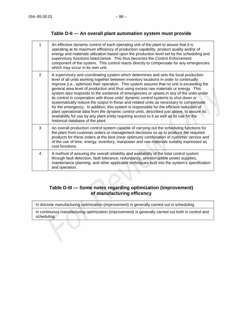
ISA–95.00.01 – 98 –
Table D-II — An overall plant automation system must provide
1 An effective dynamic control of each operating unit of the plant to assure that it isoperating at its maximum efficiency of production capability, product quality and/or ofenergy and materials utilization based upon the production level set by the scheduling andsupervisory functions listed below. This thus becomes the Control Enforcementcomponent of the system. This control reacts directly to compensate for any emergencieswhich may occur in its own unit.
2 A supervisory and coordinating system which determines and sets the local productionlevel of all units working together between inventory locations in order to continuallyimprove (i.e., optimize) their operation. This system assures that no unit is exceeding thegeneral area level of production and thus using excess raw materials or energy. Thissystem also responds to the existence of emergencies or upsets in any of the units underits control in cooperation with those units’ dynamic control systems to shut down orsystematically reduce the output in these and related units as necessary to compensatefor the emergency. In addition, this system is responsible for the efficient reduction ofplant operational data from the dynamic control units, described just above, to assure itsavailability for use by any plant entity requiring access to it as well as its use for thehistorical database of the plant.
3 An overall production control system capable of carrying out the scheduling functions forthe plant from customer orders or management decisions so as to produce the requiredproducts for these orders at the best (near optimum) combination of customer service andof the use of time, energy, inventory, manpower and raw materials suitably expressed ascost functions.
4 A method of assuring the overall reliability and availability of the total control systemthrough fault detection, fault tolerance, redundancy, uninterruptible power supplies,maintenance planning, and other applicable techniques built into the system’s specificationand operation.
Table D-III — Some notes regarding optimization (improvement)of manufacturing efficency
In discrete manufacturing optimization (improvement) is generally carried out in scheduling.
In continuous manufacturing optimization (improvement) is generally carried out both in control andscheduling.

– 99 – ISA–95.00.01–2000
Table D-IV — Summary of duties of control computer systems
I. Production Scheduling
II. Control Enforcement
III. Plant Coordination and Operational Data Reporting
IV. System Reliability and Availability Assurance
Item I of the above list (Production Scheduling) corresponds to Item 3 of the list of Table D-II.
Item II of the above list corresponds to much of Items 1 and 2 of the list of Table D-II.
Items III and IV of the above list require the cooperative operation of all items of the list of Table D-II. ThePlant Coordination part comprises the detailed interpretation and expansion of the overall ProductionSchedule of Item 3 of Table D-II.
It is our contention that such lists can outline the tasks that must be carried out in any industrial plant,particularly at the upper levels of the hierarchy. Details of how these operations are actually carried outmay vary drastically, particularly at the lowest levels, because of the nature of the actual process beingcontrolled. We all recognize that a distillation column will never look like or respond like an automobileproduction line. But the operations themselves remain the same in concept, particularly at the upperlevels of the hierarchy.
Thus it is our further contention that despite the different nomenclature in different industries the majordifferences in the control systems involved is concentrated in the details of the dynamic controltechnologies used at Level 1 and the details of the mathematical models used for optimization at Level 2.
The differences are thus concentrated in the details of the control and operation of the individualproduction units (the application entities) of the factory. Commonality is in the support functional entities(computational services, communications, database technology, management structure, etc.). Sensingand communication techniques are exactly the same in both systems. The same optimization algorithmscan be used. Computer systems technology and programming techniques should be the same andproduction scheduling technology should be identical to name only a few.
Thus the duties of the hierarchical computer system can be established as outlined in Table D-IV and infigure D-4. Therefore Levels 1 and 2 will concentrate on performing Task II of Table D-IV, Levels 3 and 4will carry out Task I and all will be involved in assuring the implementation of Task III and the integrity ofTask IV, overall reliability and availability.
Possibilities of major reduction in the costs, development manpower effort, and time required to producean integrated industrial control system then devolves upon the factors listed in Table D-V.

ISA–95.00.01 – 100 –
(LEVEL 4)
MANAGEMENTDATA
PRESENTATION
OPERATIONAL ANDPRODUCTIONSUPERVISION
PLANTMANAGEMENTINFORMATION
PLANT PRODUCTIONSCHEDULING AND
OPERATIONALMANGEMENT
SA
LES
OR
DE
RS
CO
MM
UN
ICA
TIO
NS
WIT
H O
TH
ER
AR
EA
S
SUPERVISOR’SCONSOLE
INTRA-AREACOORDINATION
CO
MM
UN
ICA
TIO
NS
WIT
H O
TH
ER
SU
PE
RV
ISO
RY
SY
ST
EM
S
SUPERVISOR’SCONSOLE
SUPERVISORYCONTROL
CO
MM
UN
ICA
TIO
NS
WIT
H O
TH
ER
CO
NT
RO
LS
YS
TE
MS
OPERATOR’SCONSOLE
DIRECT DIGITALCONTROL
(LEVEL 3)
(LEVEL 2)
(LEVEL 0)
SPECIALIZED DEDICATED DIGITALCONTROLLERS
PROCESS
ALL
PH
YS
ICA
L,
CH
EM
ICA
L O
RS
PA
TIA
LT
RA
NS
FO
RM
AT
ION
S
CONTROL
COMPUTIT
ION,
AND
CONTROL
ENFORCEMENT
LEVEL 4A
LEVEL 4B
PRODUCTION
SCHEDULING
AND
MANAGEM
ENT
INFORM
ATION
(LEVEL 1)
Figure D-4 — Definition of the real tasks of the hierarchical computer controlsystem (as modified in ISA-95.00.01-2000)

– 101 – ISA–95.00.01–2000
Table D-V — Potential factors for facilitating integrated control systemdevelopment and use
1. Potential commonality of control system structure in terms of the:
A. Computer systems
B. Communications systems
C. Database organization
D. Relationship to plant management and operational structure (personnel)
2. Commonality of the techniques of application of:
A. Software engineering and programming
B. Communications
C. Database management
D. Control systems engineering
E. Production scheduling
F. Operations research and optimization
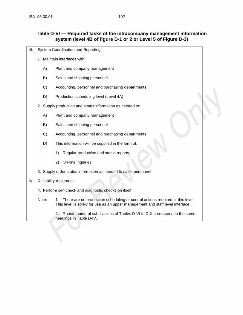
ISA–95.00.01 – 102 –
Table D-VI — Required tasks of the intracompany management informationsystem (level 4B of figure D-1 or 2 or Level 5 of Figure D-3)
III. System Coordination and Reporting
1. Maintain interfaces with:
A) Plant and company management
B) Sales and shipping personnel
C) Accounting, personnel and purchasing departments
D) Production scheduling level (Level 4A)
2. Supply production and status information as needed to:
A) Plant and company management
B) Sales and shipping personnel
C) Accounting, personnel and purchasing departments
D) This information will be supplied in the form of:
1) Regular production and status reports
2) On-line inquiries
3. Supply order status information as needed to sales personnel
IV. Reliability Assurance
4. Perform self-check and diagnostic checks on itself
Note: 1. There are no production scheduling or control actions required at this level.This level is solely for use as an upper management and staff level interface.
2. Roman numeral subdivisions of Tables D-VI to D-X correspond to the sameheadings in Table D-IV.

– 103 – ISA–95.00.01–2000
Table D-VII — Duties of the production scheduling and operationalmanagement level (levels 4A or 5A)
I. Production Scheduling
1. Establish basic production schedule.
2. Modify the production scheduling for all units per order stream received, energyconstraints, power demand levels, and maintenance requirements.
3. In coordination with required production schedule develop optimum preventivemaintenance and production unit renovation schedule.
4. Determine the optimum inventory levels of raw materials, energy sources, spareparts, etc., and of goods in process at each storage point. The criteria to be usedwill be the trade-off between customer service (i.e., short delivery time) versus thecapital cost of the inventory itself, as well as the trade-offs in operating costsversus costs of carrying the inventory level. This function will also include thenecessary material requirements planning (MRP) and spare parts procurement tosatisfy the production schedule planned. (This is an off-line function.)
5. Modify production schedule as necessary whenever major production interruptionsoccur in downstream units, where such interruptions will affect prior or succeedingunits.
III. Plant Coordination and Operational Data Reporting
6. Collect and maintain raw material and spare parts use and available inventory andprovide data for purchasing for raw material and spare parts order entry and fortransfer to accounting.
7. Collect and maintain overall energy use and available inventory and provide datafor purchasing for energy source order entry and for transfer to accounting.
8. Collect and maintain overall goods in process and production inventory files.
9. Collect and maintain the quality control file.
10. Collect and maintain machinery and equipment use and life history files necessaryfor preventive and predictive maintenance planning.
11. Collect and maintain manpower use data for transmittal to personnel andaccounting departments.
12. Maintain interfaces with management interface level function and with area levelsystems.
IV. Reliability Assurance
13. Run self-check and diagnostic routines on self and lower level machines.
Note: There are no control functions as such required at this level. This level is for theproduction scheduling and overall plant data functions.
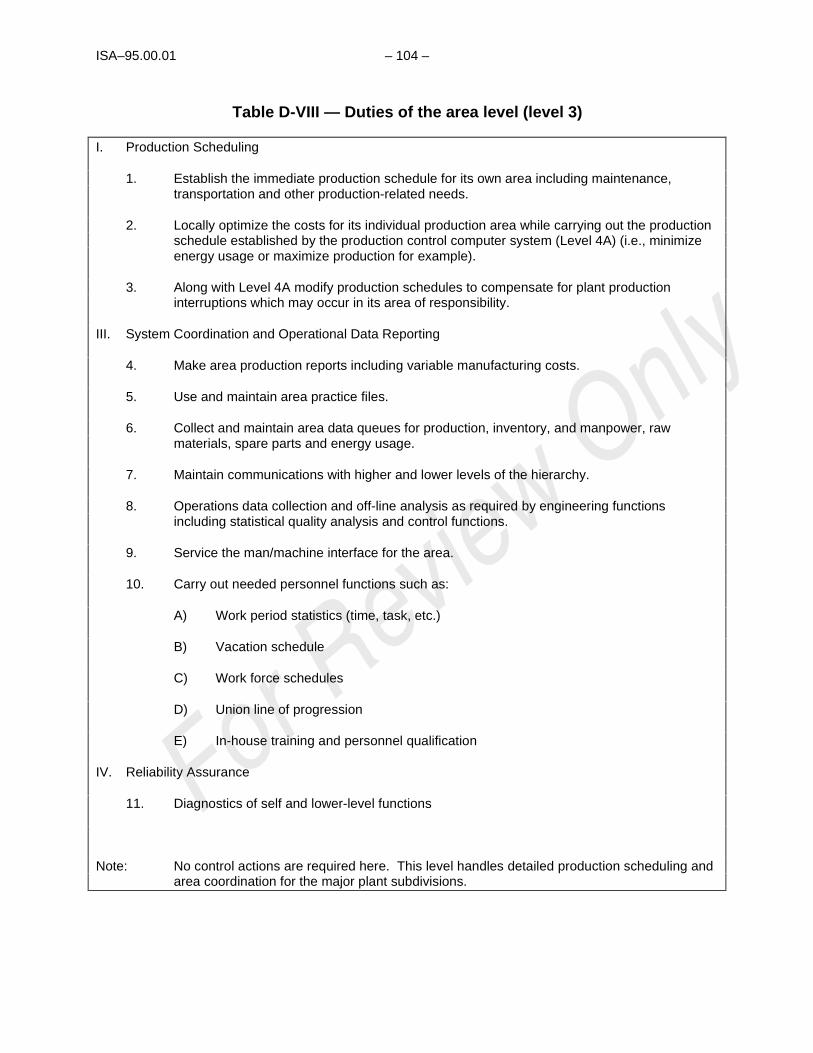
ISA–95.00.01 – 104 –
Table D-VIII — Duties of the area level (level 3)
I. Production Scheduling
1. Establish the immediate production schedule for its own area including maintenance,transportation and other production-related needs.
2. Locally optimize the costs for its individual production area while carrying out the productionschedule established by the production control computer system (Level 4A) (i.e., minimizeenergy usage or maximize production for example).
3. Along with Level 4A modify production schedules to compensate for plant productioninterruptions which may occur in its area of responsibility.
III. System Coordination and Operational Data Reporting
4. Make area production reports including variable manufacturing costs.
5. Use and maintain area practice files.
6. Collect and maintain area data queues for production, inventory, and manpower, rawmaterials, spare parts and energy usage.
7. Maintain communications with higher and lower levels of the hierarchy.
8. Operations data collection and off-line analysis as required by engineering functionsincluding statistical quality analysis and control functions.
9. Service the man/machine interface for the area.
10. Carry out needed personnel functions such as:
A) Work period statistics (time, task, etc.)
B) Vacation schedule
C) Work force schedules
D) Union line of progression
E) In-house training and personnel qualification
IV. Reliability Assurance
11. Diagnostics of self and lower-level functions
Note: No control actions are required here. This level handles detailed production scheduling andarea coordination for the major plant subdivisions.

– 105 – ISA–95.00.01–2000
Table D-IX — Duties of the supervisory level (level 2)
II. Control Enforcement
1. Respond to any emergency condition which may exist in its region of plant cognizance.
2. Optimize the operation of units under its control within limits of established productionschedule. Carry out all established process operational schemes or operating practices inconnection with these processes.
III. System Coordination and Operational Data Reporting
3. Collect and maintain data queues of production, inventory, and raw material, spare parts andenergy usage for the units under its control.
4. Maintain communications with higher and lower levels.
5. Service the man/machine interfaces for the units involved.
IV. Reliability Assurance
6. Perform diagnostics on itself and lower level machines.
7. Update all standby systems.
Note: This level and those below it carry out the necessary control and optimization functions forthe individual production units to enforce the production schedule set by Levels 4A and 3.

ISA–95.00.01 – 106 –
Table D-X — Duties of the control level (level 1)
II. Control Enforcement
1. Maintain direct control of the plant units under its cognizance.
2. Detect and respond to any emergency condition which may exist in these plant units.
III. System Coordination and Reporting
3. Collect information on unit production, raw material and energy use and transmit to higherlevels.
4. Service the operator’s man/machine interface.
IV. Reliability Assurance
5. Perform diagnostics on itself.
6. Update any standby systems.
Notes: It has repeatedly been shown that one of the major benefits of the use of digital computercontrol systems in the automation of industrial plants has been in the role of a Control Systems Enforcer . In this mode, one of the control computer’s main tasks is to continually assure that the control system equipment is actually carrying out the job that it was designedto do in keeping the units of the plant production system operating at some best (nearoptimal) level.
That is, to be sure that in the continuous process plant, for instance, the controllers have notbeen set on manual, that the optimal set points are being maintained, etc. Likewise, it is thetask of dynamic control to assure that the plant’s production schedule is carried out, i.e., toenforce the task set by the production scheduling function.
In the Purdue Reference Model definition there are no Informational Transformations at Level0.
Sensors determine the state of the physical equipment or the material being transformedtherein. All operations on the resulting data are informational. Sensor outputs areconsidered part of Level 1.
Actuators are considered part of Level 0 - commands to them are considered Level 1.

– 107 – ISA–95.00.01–2000
Tasks of Each Level of the Hierarchy
In the context of any large industrial plant, or of a complete industrial company based in one location, thetasks that would be carried out at each level of the hierarchy are as described in Tables D-VI to D-X.Note that these tasks are subdivided within each table into those related to production scheduling, controlenforcement, systems coordination and reporting, and reliability assurance (Table D-IV). As wasmentioned above, these tables outline the tasks which must be carried out in any industrial plant,particularly at the upper levels of the hierarchy.
Figures D-5 to D-10 show the application of the Scheduling and Hierarchy View to a variety of industriesshowing also that the computer control system discussed here is pyramidal as well as hierarchical.Figure D-10 is an entirely different appearing diagram as originally developed by the Cincinnati-MilacronCompany. However with the current CIM hierarchy levels imposed it can be readily seen that thisdiagram converts directly to the others.
Figures D-5 to D-10 also bring out an important aspect of this model in relation to those proposed bysome other developers, that is, inventories and associated material handling equipment in relation to themanufacturing processes themselves are treated just like any other process. Thus they are considered tohave process control inputs and outputs and their dynamic behavior can be modeled mathematically inorder to develop the appropriate overall control system for the functions served by the inventory and itsassociated material handling equipment.
The Data-Flow Graph, a Functional Network View of the CIM Reference Model
There is need in the Reference Architecture to have a mechanism to show the interconnection andprecedence of the several tasks assigned to the overall mill-wide control system which is not shown bythe Scheduling and Control Hierarchy view. An excellent method for showing this is the so-calledData-Flow Graph or Information-Flow Graph using a technique known as Structured Analysis,10 alsoknown as the Yourdon-DeMarco technique.
This clause will develop such a representation as derived from the CIM Reference Model. The basis forthis work will be a Data-Flow Model entitled, Information Flow Model of Generic Production Facility, contributed to the Purdue Reference Model for CIM project by The Foxboro Company in August 1986.11
The original document has been considerably modified by the Workshop CIM Committee to match thenomenclature, etc., of other parts of the model's documentation.
As noted above, this method diagrams the interconnection of the several tasks carried out by the controlsystem and allows the potential for an ever greater detailing of these tasks in the form of sub-tasks andthe resulting interconnections of these sub-tasks with each other and the main tasks. These diagramsare restricted to the model as defined in the Purdue Reference Model for CIM (i.e., the definablescheduling and control system for the manufacturing facility and including only interfaces to the externalinfluences), i.e., the Integrated Information Management and Control System of Figure D-11 and theInformation Systems Architecture of this text.
The set of diagrams begins with the interconnection of the influencing external entities on the factory itself(Figure D-12). In the present model one very important external influence on the factory is the companymanagement itself. As noted in Figure D-13 management interfaces through the staff departments whoprovide services to the factory itself or express management's policies in sets of requirements to befulfilled by the factory.
______
10 DeMarco, T., Structured Analysis and System Specification, Prentice-Hall, Inc., Upper Saddle River , NJ (1978)
11 Pampel, Albert., Information Flow Model of a Generic Production Facility, The Foxboro Company, Foxboro, MA (1986)

ISA–95.00.01 – 108 –
It will be immediately noticed by the reader that the two lists of tasks and functions we are developinghere look entirely different even though each is a complete listing within itself. This is because these twodifferent models of the Information Architecture show different ones of the task and function relationships.The Scheduling and Control Hierarchy shows subordination, precedence, time horizon and span ofcontrol, while the Data Flow Diagram shows connectivity and precedence. Thus since there is nolayering in the Data Flow diagram (subordination) and no connectivity in the Scheduling and Controlhierarchy, their views of the tasks and functions are greatly different. This results in a different definitionof each task in many cases particularly because of a difference in span of concern. Therefore thedescription and labels may be (and are) different between the two models.
Table D-XI presents the functions and tasks listed on the diagrams of Figures D-16 to D-28. Table D-XIImakes a comparison of the tasks listed in Tables D-VI to D-X versus those on Figures D-16 to D-28 asdiscussed just above.
OVERALL
AREA 2 AREA 3AREA 1
(4A,B)
(3)
(MELTING) (HOT ROLLING) (COLD WORKING)
IRON MAKING
S TEEL MAKING
S LABS HOT BANDS
IN P
RO
CE
SS
IN
VE
NT
OR
Y
IN P
RO
CE
SS
IN
VE
NT
OR
Y
COLD BANDS
FINIS HING
REHEAT FURNACE
ROUGHING FINISHING DOWN COILERS AND
INVENTORY
STAND CONTROL
(2)
(1)
NORMAL COMMUNICATION PATH
"AS NEEDED" COMMUNICATION PATH
Figure D-5 — Hierarchy arrangement of the steel plant control to showrelationship of hierarchy to plant structure
OVERALL
AREA 1 (MELTING)
AREA 2 (HOT ROLLING)
AREA 3 (COLD ROLLING)
AREA 4(ENERGY MANAGEMENT)
HOT BANDS
FINISHINGCOLD BANDS
GASEOUS AND LIQUID FUEL COLLECTION
AND DISTRIBUTION
SYSTEM
STEAM AND ELECTRIC PLANT
AND STEAM DISTRIBUTION
ELECTRIC POWER
DISTRIBUTION SYSTEM
COKE OVENS
SINTER PLANT
IRON MAKING
CONTIN-UOUS
CASTING SLABS (INGOT PROCESSING)
STEEL MAKING
LEVEL 4
LEVEL 3
LEVEL 2
Figure D-6 — Hierarchy arrangement of the steel plant control system asstudied for energy optimization

– 109 – ISA–95.00.01–2000
OVERALL
AREA 2 AREA 3AREA 1
(PULP MILL) (PAPER MILL) (ENERGY RECOVERY AND ENVIRONMEMT)
WOODYARD AND PULPING
BLEACHING STOCK PREPAR-
ATION
PAPER MACHINE
IN P
RO
CE
SS
IN
VE
NT
OR
Y
IN P
RO
CE
SS
IN
VE
NT
OR
Y
EVAPORATORS AND RECOVERY
BOILERS
LIME KILN AND
CAUSTICIZING
NORMAL COMMUNICATION PATH
"AS NEEDED" COMMUNICATION PATH
WASTE TREATMENT
ROLL HANDLING
AND FINISHING
HEAD BOXDRYING
REELING AND ROLL HANDLING
SLICE CONTROL
Figure D-7 — Hierarchy arrangement of the paper mill control to showrelationship of hierarchy to plant structure
OVERALL
AREA 2 AREA 3AREA 1
(4 A,B)
(3 )
PRIMARY RAW
MATERIAL HANDLING
PREPARATION OF INTERMEDIATES
POLYMERIZATION OR OTHER PREPARATION OF FINAL PRODUCTS
IN P
RO
CE
SS
IN
VE
NT
OR
Y
IN P
RO
CE
SS
IN
VE
NT
OR
Y(2 )
(1 )
CRUDE DISTILLATION
CRACKING SEPARATION REACTION SEPARATION
DISTILLATION ABSORPTION OR
EXTRACTION
DRYING
INDIV IDUAL COLUMN CONTROL
REACTION SEPARATION FINISHING
(( (( ( (
NORMAL COMMUNICATION PATH
"AS NEEDED" COMMUNICATION PATH
LEVELS
Figure D-8 — The hierarchy control scheme as applied to a petrochemical plant

ISA–95.00.01 – 110 –
OVERALL
AREA 2 AREA 3AREA 1
(4A, B)
(3 )
PRI MARY RAW MATERI AL
HANDLI NG AND I NTERMEDI ATES
PREPARATI ON
IN P
RO
CE
SS
IN
VE
NT
OR
Y
IN P
RO
CE
SS
IN
VE
NT
OR
Y
( 2 )
(1 )
NORMAL COMMUNI CATI ON PATH
"AS NEEDED" COMMUNI CATI ON PATH
PREPARTI ON OF FI NAL I NGREDI ENTS AND COMPOUNDI NG OF
PRODUCTS
PELLETI ZI NG AND OTHER PREPARATI ONS OF UNI T
DOSAGE QUANTI TI ES, PACKAGI NG AND
WAREHOUSI NG
RAW MATERI ALS HANDLI NG
REACTI ONS NECESSARY
FOR I NTERMEDI ATE PREPARATI ON
SEPARATI ON
FERMENTATI ON AND OTHER
REACTI ON STEPS
SEPARATI ON PELLETI ZI NG, ETC.
PACKAGI NG WAREHOUSI NG
DI STI LLATI ON ABSORPTI ON OR EXTRACTI ON
CRYSTALLI ZATI ON
DRYI NG
I NDI VI DUAL COLUMN CONTROL
(
(
(
(
(
(
Figure D-9 — The hierarchy control scheme as applied to a pharmaceuticals plant
S HOP COORDINATOR
CENTRAL DATA BAS E
PROCES S PLANNING
S YS TEM
PRODUCTION S CHEDULING
AND CONTROL
LEVEL 4
LEVEL 3
DNC MONITORING MAINTE NANCESHOP
COMMUNI- CATION
FUNCTIONAL S HOP
CE LLULAR MANUFACTURING
COMPUTER CONTROLLED
MACHINING S YS TE M (CCMS)
CO MPUTER CONTROLLED
AS SEMBLY SYSTEMLEVEL 1 {
LEVEL 2
MANUFACTURING S ERV ICES S TORAGE AND RE TRIEVAL
WORK PRE PARATION MATE RIAL HANDLING
Figure D-10 — Computer integrated manufacturing system (CIMS)(Cincinnati-Milicron proposal)

– 111 – ISA–95.00.01–2000
Table D-XI — Information flow model of generic production facility mini-specs(definition of functions)
FIRST ORDER ENTITY DIVISIONS
0. FACILITY MODEL CONTEXT - Figure D-16External EntitiesMarketing and SalesCorporate R. D. & E.SupplierVendorCustomerTransport CompanyAccountingPurchasing
1. ORDER PROCESSING - Bubble 1 of Figure D-16 and Figure D-17Customer order handling, acceptance and confirmationSales forecastingWaiver and reservation handlingGross margin reportingDetermine production orders
2. PRODUCTION SCHEDULING - Bubble 2 and Figure D-18Determine production scheduleIdentify long term raw material requirementsDetermine packout schedule for end productsDetermine available product for sales
3. PRODUCTION CONTROL - Bubble 3 and Figure D-19Control of transformation of raw materials into end product in accordance with production schedule and production standardsMaintenance of processing equipmentPlant engineering and updating of process plans, etc.Issue requirements for raw materialsProduce reports of performance and costsEvaluate constraints to capacity and qualitySelf test and diagnostics of production and control equipment
4. MATERIALS AND ENERGY CONTROL - Bubble 4 and Figure D-23Keep stock of raw materialsReorder raw materials according to production RequirementsAccept delivery of raw materials, request QA tests and release for utilization after approvalReporting on RM and energy utilizationReporting on RM inventory to production
5. PROCUREMENT - Bubble 5 and Figure D-24Place orders with suppliers for RM supplies, spare parts, tools, equipment and other required materialsMonitor progress of purchases and report to requisitionersRelease incoming invoices for payment after arrival and approval of goods
6. QUALITY ASSURANCE - Bubble 6 and Figure D-25Testing and classification of incoming material and end productsSet standard for production QA in accordance with market and technology requirementsAssist production with exceptional and effective QA tests
7. PRODUCT INVENTORY - Bubble 7 and Figure D-26Keep stock of produced end productsMake reservation for specific product on list in accordance with product selling directivesPack-out end product in accordance with scheduleReport on inventory to production schedulingReport on balance and losses to product cost accountingArrange physical loading/shipment of goods in coordination with product shipping administration

ISA–95.00.01 – 112 –
Table D-XI (continued)
8. COST ACCOUNTING - Bubble 8 and Figure D-27Calculate and report on total product costReport cost results to production for adjustmentSet cost objectives for production
9. PRODUCT SHIPPING ADMINISTRATION - Bubble 9 and Figure D-28Organize transport for product shipment in accordance with accepted orders requirementsNegotiate and place orders with transport companiesAccept freight items on site and release material for shipmentPrepare accompanying documents for shipment (BOL, customs clearance)Confirm shipment and release for invoicing to general accountingReport on shipping costs to product cost accounting
(10.0 MAINTENANCE (Defined as a FIRST ORDER ENTITY in the ISA-95.00.01-2000 model)
SECOND-ORDER ENTITY SUBDIVISIONS
1.1 PRODUCTION FORECASTING (LONG RANGE) - Bubble 1.1, Figure D-17The orders expected within the next period of time are predictedThe prediction is based on the sales history and function of the market expectationForecasting makes use of the traditional statistical techniques (smoothing, seasonal indices, etc.)The forecasting period is set by the confidence of market expectationsMarket expectations are influenced by outside factors, e.g., economical or political situation, or by inside factors, e.g., longterm contracts, production problems
1.2 HISTORIAN - Bubble 1.2 , Figure D-17Create and update a sales history file with clarification of product, customer, shipping method
1.3 ORDER ENTRY - Bubble 1.3, Figure D-17Main interface with customer for inquiries and ordersSupply product price and availabilityHandle order entry and amendmentsGive confirmation and progress of entered orders
1.4 PRODUCTION ORDER - Bubble 1.4, Figure D-17Based on active and forecasted orders determine the required production
1.5 ORDER ACCEPTANCE - Bubble 1.5, Figure D-17Handle the acceptance for delivery of entered ordersAcceptance is based on ability to manufacture and availability of product customer credibility is checkedIn specific cases the product specifications can be waived in accordance with marketing policies to ratify a particular customeror market need
2.1 PROCESS PRODUCTION ORDERS - Bubble 2.1, Figure D-18Produce detailed production requirements from sales production ordersHighlight specification requirements for non-standard requestsProduce production order entry in scheduling file and append shipment requirements
2.2 BALANCE IN PROCESS AND PRODUCTION INVENTORY - Bubble 2.2, Figure D-18Identify ordered quantities against produced products and initiate packout of specific shipmentsIdentify availability of on-hand productHighlight variance in production scheduleMaintain capacity estimates for production facility in terms of products
2.3 PRODUCTION FORECASTING (SHORT TERM) - Bubble 2.3, Figure D-18From existing production orders and known capacity, produce specific schedule entries for production rates and specificationsSet long term raw material order rates to meet production scheduleProduce a long term forecast report

– 113 – ISA–95.00.01–2000
Table D-XI (continued)
2.4 PRODUCTION SCHEDULING - Bubble 2.4, Figure D-18Produce formal production scheduleModify production schedule to account for production variances and interruptionsModify production schedule to account for inventory and shipments
3.1 PROCESS SUPPORT ENGINEERING - Bubble 3.1, Figure D-19; Figure D-20Issue request for modification or maintenanceCoordinate maintenance and engineering activitiesProvide technical standards and methods to maintenance functionFollow-up on equipment and process performanceProvide technical support to operatorsFollow-up on technological developmentsProvide specifications for purchase order requests
3.2 MAINTENANCE - Bubble 3.2, Figure D-19; Figure D-21 (10.0 in theISA-95.00.01-2000 Model)Provide maintenance for existing installationsProvide preventative maintenance programProvide equipment monitoring program to anticipate Failure including self-check and diagnostic programsPlace purchase order request for materials and spare partsDevelop maintenance cost reportsCoordinate outside contract work effort
3.3 OPERATIONS CONTROL - Bubble 3.3, Figure D-19; Figure D-22Supervise the operations of production processKeep track and report on production costs and performanceInterpret the production plan in terms of the setpoints to individual unitsDiagnostics and self-check of production and control equipment
3.4 OPERATIONS PLANNING - Bubble 3.4, Figure D-19Set up a daily production plan as function of the production scheduleCheck schedule against raw material availability and product storage capacityDetermine percent of capacity statusModify production plan hourly to account for equipment outage, manpower and raw materials availability
4.1 MATERIAL AND ENERGY REQUIREMENT CONTROL - Bubble 4.1, Figure D-23Determine supplier of new materials based on short and/or long term requirements from planning or manufacturing takingexisting inventory into accountSet up transfers of materials and energy to manufacturingIssue purchase request for new material and energy suppliesNotify incoming material and energy control on expected incoming orders
4.2 OPTIMUM MATERIAL AND ENERGY INVENTORY LEVELS - Bubble 4.2, Figure D-23Continuously calculate and report inventory balance and losses of RM and energy utilization
4.3 INCOMING RAW MATERIAL AND ENERGY CONTROL - Bubble 4.3, Figure D-23Receive incoming material and energy supplies and request QA testsTransfer material and energy to storage and/or classify for use after QA approvalNotify purchasing of accepted material and energy supplies to release payment
4.4 RAW MATERIAL AND ENERGY ROUTING - Bubble 4.4, Figure D-23Set up and monitor the movement of material and energy in storageUpdate inventory of all movements and changes
4.5 RAW MATERIAL AND ENERGY INVENTORY REPORTING - Bubble 4.5, Figure D-23Reporting of inventory to production
4.6 RAW MATERIAL AND ENERGY MOVEMENT CONTROL - Bubble 4.6, Figure D-23Control and monitor transfer of materials
4.7 DRAW MATERIALS AND ENERGY MEASUREMENT VALIDATION - Bubble 4.7, Figure D-23See 3.3.4

ISA–95.00.01 – 114 –
Table D-XI (continued)
5.1 ORDER PLACEMENT - Bubble 5.1, Figure D-24Order preparation for raw materials, spare parts, etc., for presentation to the vendors based on procurement contractsnegotiated by company purchasingUpdating of vendor library and purchasing files of vendors performance on orders
5.2 PROCESS REQUESTS - Bubble 5.2, Figure D-24Collection and processing of unit requests for raw materials, spare parts, etc., for order placement to vendorsChecking of requests for those materials versus historical files and budgets to assure correctness of requests
5.3 COST CONTROL - Bubble 5.3, Figure D-24Certification of invoices on raw materials and spare parts based on satisfactory receipt of requested materials or parts
6.1 SET STANDARDS AND METHODS - Bubble 6.1, Figure D-25Issue standards to manufacturing and testing laboratories in accordance with requirements from technology, marketing andcustomer services
6.2 RAW MATERIALS EVALUATION - Bubble 6.2, Figure D-25Testing of incoming raw materials and approval for use if in accordance with set standardsCollect and maintain quality control file for data for quality control analysis
6.3 EVALUATION OF PRODUCT - Bubble 6.3, Figure D-25Test of final product and report results to classificationCollect and maintain quality control file for data for quality control analysis
6.4 CLASSIFICATION AND CERTIFICATION - Bubble 6.4, Figure D-25Classify quality and properties of end product in accordance with set marketing standardsWaiver classification on exceptional basis as per request from product sellingReport QA results and classification to finished product inventory controlCertify that product was produced according to standard process conditionsReport process data and certification to finished product inventory control
6.5 QA MEASUREMENT VALIDATION - Bubble 6.5, Figure D-25Checking of product data versus customer’s requirements and statistical quality control routines to assure adequate qualitybefore shipmentMaintenance of quality statistics on each item checked for continuing quality control studies.
6.6 LABORATORY AND AUTOMATIC ANALYSIS - Bubble 6.6, Figure D-25Conduct of metric, chemical and physical tests on sample product items to obtain data for on-going quality control testsTransmission of this data to analysis facilities and quality control systems to assure future quality of product
6.7 ANALYZE PROCESS CAPABILITY - Bubble 6.7, Figure D-25Use SQC methodology to examine product data to determine process capability of meeting product specificationsRelay process deviations to process engineering for reevaluation to upgrade processRelay methods deviation to standards and methods group for corrective action
7.1 INVENTORY SUPERVISION - Bubble 7.1, Figure D-26Coordinate all activities in product inventory controlSet up transfers of material to packing unit in accordance to packout scheduleRequest replenishment of packing materialsHandle reservations and update inventory accordingly
7.2 LOSS CONTROL - Bubble 7.2, Figure D-26Continuously calculate and report on inventory balance and losses
7.3 INVENTORY REPORTING - Bubble 7.3, Figure D-26Generate daily, weekly ... reports on actual amounts of materials in storage
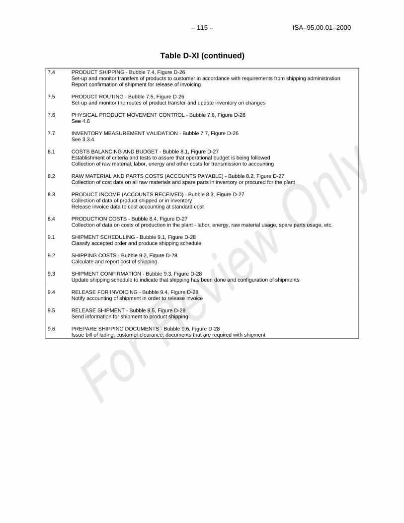
– 115 – ISA–95.00.01–2000
Table D-XI (continued)
7.4 PRODUCT SHIPPING - Bubble 7.4, Figure D-26Set-up and monitor transfers of products to customer in accordance with requirements from shipping administrationReport confirmation of shipment for release of invoicing
7.5 PRODUCT ROUTING - Bubble 7.5, Figure D-26Set-up and monitor the routes of product transfer and update inventory on changes
7.6 PHYSICAL PRODUCT MOVEMENT CONTROL - Bubble 7.6, Figure D-26See 4.6
7.7 INVENTORY MEASUREMENT VALIDATION - Bubble 7.7, Figure D-26See 3.3.4
8.1 COSTS BALANCING AND BUDGET - Bubble 8.1, Figure D-27Establishment of criteria and tests to assure that operational budget is being followedCollection of raw material, labor, energy and other costs for transmission to accounting
8.2 RAW MATERIAL AND PARTS COSTS (ACCOUNTS PAYABLE) - Bubble 8.2, Figure D-27Collection of cost data on all raw materials and spare parts in inventory or procured for the plant
8.3 PRODUCT INCOME (ACCOUNTS RECEIVED) - Bubble 8.3, Figure D-27Collection of data of product shipped or in inventoryRelease invoice data to cost accounting at standard cost
8.4 PRODUCTION COSTS - Bubble 8.4, Figure D-27Collection of data on costs of production in the plant - labor, energy, raw material usage, spare parts usage, etc.
9.1 SHIPMENT SCHEDULING - Bubble 9.1, Figure D-28Classify accepted order and produce shipping schedule
9.2 SHIPPING COSTS - Bubble 9.2, Figure D-28Calculate and report cost of shipping
9.3 SHIPMENT CONFIRMATION - Bubble 9.3, Figure D-28Update shipping schedule to indicate that shipping has been done and configuration of shipments
9.4 RELEASE FOR INVOICING - Bubble 9.4, Figure D-28Notify accounting of shipment in order to release invoice
9.5 RELEASE SHIPMENT - Bubble 9.5, Figure D-28Send information for shipment to product shipping
9.6 PREPARE SHIPPING DOCUMENTS - Bubble 9.6, Figure D-28Issue bill of lading, customer clearance, documents that are required with shipment

ISA–95.00.01 – 116 –
Table D-XI (continued)
THIRD-ORDER ENTITY SUBDIVISIONS
3.1.1 PROJECT MANAGEMENT - Bubble 3.1.1, Figure D-20Management of engineering functionCoordination of equipment and process modificationCost and progress reportingProject planningDesign follow-up with corrective action
3.1.2 EQUIPMENT AND PROCESS DESIGN MODIFICATION - Bubble 3.1.2, Figure D-20Establish design basis of new projectSupply necessary information to allow cost estimatingReport and Coordinate Specialists’ AssistanceProvide Technical Information to Operators
3.1.3 ENGINEERING SPECIALISTS - Bubble 3.1.3, Figure D-20Provide support and advice in special areaFollow-up on state of the art in technologyAssess plant process and equipment performanceAdjust standards and methods to needs and progressMonitor the interpretation of design basis during detailed engineering
3.1.4 STANDARDS AND METHODS - Bubble 3.1.4, Figure D-20Establish standards for process equipment, design techniques and process operational methods (practice files)Promulgate such standards within the process support engineering functions and within the operational groups of the
factory
3.1.5 PROJECT COST CONTROL - Bubble 3.1.5, Figure D-20Provide cost estimates of planned projectsFollow-up and report on costs of projects in execution
3.1.6 PROCESS ANALYSIS AND PROJECT DETAILED ENGINEERING - Bubble 3.1.6, Figure D-20Conduct plant performance studiesProvide details for the construction of equipment or process modification project in accordance to design basisIssue report for ordering of new equipmentIssue specifications to vendorReport on engineering and committed equipment costs
3.1.7 EQUIPMENT MODIFICATION CONSTRUCTION - Bubble 3.1.7, Figure D-20Provide for construction of projectReport on cost and labor
3.1.8 DRAFTING DOCUMENTATION - Bubble 3.1.8, Figure D-20Maintain master copies of all plant drawings for units under its cognizanceResponsible for updating drawings and associated documentation as units are modifiedSupply copies as needed
3.2.1 MAINTENANCE PLANNING - Bubble 3.2.1, Figure D-21Organization and supervision of requested maintenanceReporting on performed maintenanceCoordinate planned work with operators and plant supervisionMonitor and update maintenance history file
3.2.2 MAINTENANCE COST CONTROL - Bubble 3.2.2, Figure D-21Follow-up on used spare parts, report maintenance labor and report on maintenance costs
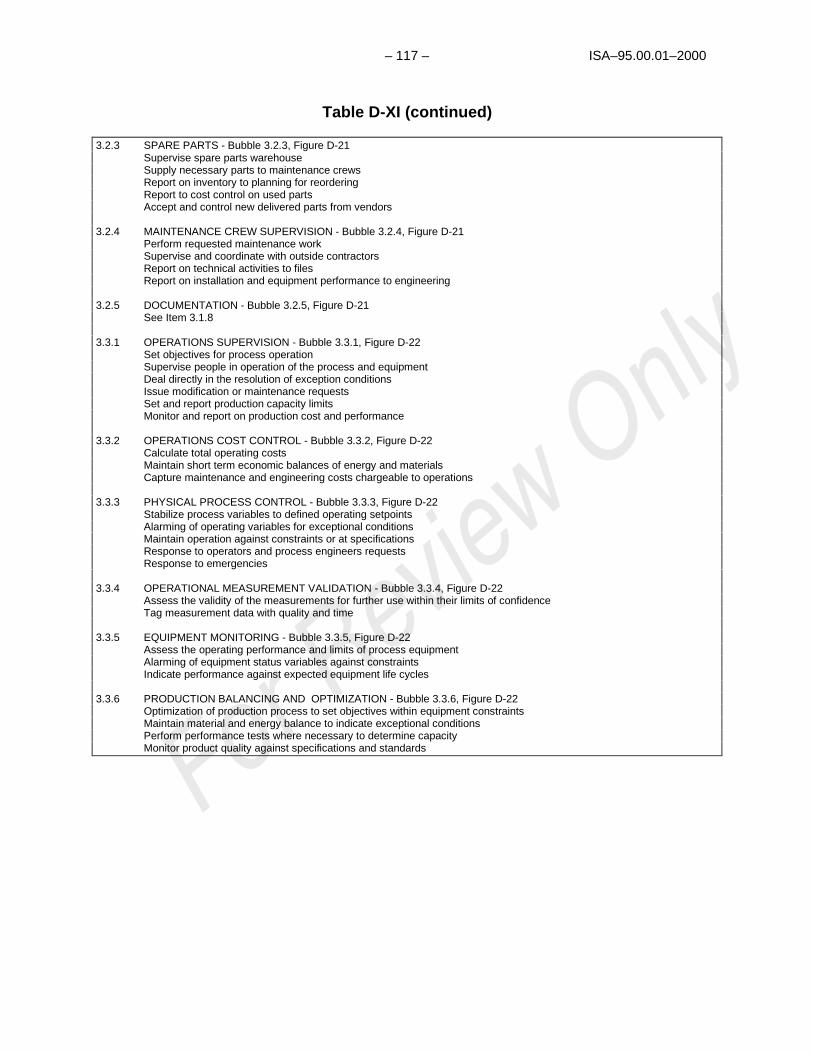
– 117 – ISA–95.00.01–2000
Table D-XI (continued)
3.2.3 SPARE PARTS - Bubble 3.2.3, Figure D-21Supervise spare parts warehouseSupply necessary parts to maintenance crewsReport on inventory to planning for reorderingReport to cost control on used partsAccept and control new delivered parts from vendors
3.2.4 MAINTENANCE CREW SUPERVISION - Bubble 3.2.4, Figure D-21Perform requested maintenance workSupervise and coordinate with outside contractorsReport on technical activities to filesReport on installation and equipment performance to engineering
3.2.5 DOCUMENTATION - Bubble 3.2.5, Figure D-21See Item 3.1.8
3.3.1 OPERATIONS SUPERVISION - Bubble 3.3.1, Figure D-22Set objectives for process operationSupervise people in operation of the process and equipmentDeal directly in the resolution of exception conditionsIssue modification or maintenance requestsSet and report production capacity limitsMonitor and report on production cost and performance
3.3.2 OPERATIONS COST CONTROL - Bubble 3.3.2, Figure D-22Calculate total operating costsMaintain short term economic balances of energy and materialsCapture maintenance and engineering costs chargeable to operations
3.3.3 PHYSICAL PROCESS CONTROL - Bubble 3.3.3, Figure D-22Stabilize process variables to defined operating setpointsAlarming of operating variables for exceptional conditionsMaintain operation against constraints or at specificationsResponse to operators and process engineers requestsResponse to emergencies
3.3.4 OPERATIONAL MEASUREMENT VALIDATION - Bubble 3.3.4, Figure D-22Assess the validity of the measurements for further use within their limits of confidenceTag measurement data with quality and time
3.3.5 EQUIPMENT MONITORING - Bubble 3.3.5, Figure D-22Assess the operating performance and limits of process equipmentAlarming of equipment status variables against constraintsIndicate performance against expected equipment life cycles
3.3.6 PRODUCTION BALANCING AND OPTIMIZATION - Bubble 3.3.6, Figure D-22Optimization of production process to set objectives within equipment constraintsMaintain material and energy balance to indicate exceptional conditionsPerform performance tests where necessary to determine capacityMonitor product quality against specifications and standards

ISA–95.00.01 – 118 –
INTEGRATEDINFORMATION
MANAGEMENT ANDAUTOMATION SYSTEM
(THE PRESENT CIMREFERENCE MODEL
COMPRISES THIS PART ONLY)
EXTERNAL INFLUENCES
MANUFACTURING ANDMATERIAL HANDLING
EQUIPMENT
SCHEDULING ANDCONTROL HIERARCHY
STATUS AND HISTORYINFORMATION
REQUIREMENTS SALESORDERS PLANS
FOUNDATIONFUNCTIONALENTITIES
MANUFACTURINGSPECIFIC FUNCTIONALENTITIES
PLANTPRODUCTIONMEDIA ENTITIES
LEVEL 0
SENSORREADIINGS
ACTUATIONCOMMANDS
AP
PLIC
AT
ION
FU
NC
TIO
NA
LE
NT
ITIE
SMODEL PRESENTS NEEDED
INTERFACES HERE
Figure D-11 — Relationship of the several classes of functional entitieswhich comprise the CIM reference model and computer integrated manufacturing
itself
CORPORATER, D & E
MARKETING& SALES SERVICES (E.G.
CONTRACTORS,TRANSPORTATION,
JANITORIAL, COMPANIES,ETC.)
SUPPLIERSAND VENDORS
PURCHASING (E.G.SUPPLIERS,
CONTRACTORS,ETC.)
HUMANRESOURCES
MANAGEMENT
CUSTOMER(ORDERS,
REQUIREMENTS, ETC.)
ACCOUNTINGFACILITY(0 LEVEL)
INFORMATION FLOW MODEL OF GENERALPRODUCTION FACILITY
Figure D-12 — Major external influences as used in the data flow model

– 119 – ISA–95.00.01–2000
Purchasing RD&EMarketing
andSales
HumanResources
Accounting
CorporateManagement
FACTORY LEVEL 0.0
VendorContracts
KnowHow
Require-ments
Man-Power
Manu-facturingPolicies
Requirements
EXTERNALENTITIES
Policies
Figure D-13 — Requirements interfacing of corporate management andstaff functional entities to the factory
Purchasing RD&EMarketing
andSales
HumanResources
Accounting
CorporateManagement
FACTORY LEVEL 0.0
Raw MaterialEnergy, andSpare Parts
Orders
EXTERNALENTITIES
CorporatePerformance Reporting
Request forInformation,plant tests,
and projects
Status ofproduction
orders
Manpowerperformance
data andrequirements*
Costreporting
OperationalPerformanceReports
* In succeeding diagrams, personnelrequirements are all pervasive andcan not be specifically shown. They arecollectively addressed here
Figure D-14 — Report interfacing to corporate management and staff functionalentities from the factory

ISA–95.00.01 – 120 –
REGULATIONSGOVERNMENTAL
REQUIREMENTS (SAFETYREGULATIONS, ETC)
CORPORATERD&E
FACTORY LEVEL 0.0
Figure D-15 — Interface of government regulations, etc., to the factory

– 121 – ISA–95.00.01–2000
Figure D-16 — 0.0 facility model

ISA–95.00.01 – 122 –
Figure D-17 — 1.0 order processing

– 123 – ISA–95.00.01–2000
Figure D-18 — 2.0 production scheduling

ISA–95.00.01 – 124 –
Figure D-19 — 3.0 production control

– 125 – ISA–95.00.01–2000
Figure D-20 — 3.1 process support engineering

ISA–95.00.01 – 126 –
Figure D-21 — 3.2 maintenance
* Sub-Function 3.2, Maintenance, is defined as a separate major function (10.0, Maintenance) in the ISA-95.00.01-2000 model. This was to simplify the representation of the Level 3-4 split in the discussion andassociated figures.

– 127 – ISA–95.00.01–2000
Figure D-22 — 3.3 operations control

ISA–95.00.01 – 128 –
Figure D-23 — 4.0 materials and energy control

– 129 – ISA–95.00.01–2000
Figure D-24 — 5.0 procurement
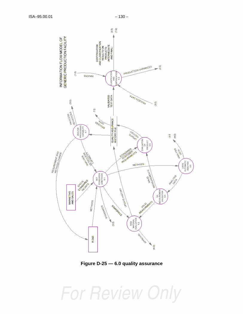
ISA–95.00.01 – 130 –
Figure D-25 — 6.0 quality assurance

– 131 – ISA–95.00.01–2000
Figure D-26 — 7.0 product inventory
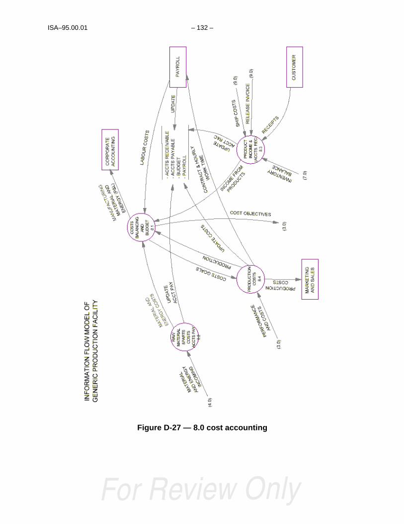
ISA–95.00.01 – 132 –
Figure D-27 — 8.0 cost accounting

– 133 – ISA–95.00.01–2000
Figure D-28 — 9.0 product shipping administration

ISA–95.00.01 – 134 –
Table D-XII — Correlation of information flow tasks with the tasks of thescheduling and control hierarchy
Data Flow Diagram Listing Scheduling and Control Hierarchy Listing
Figure No. andLocation
Title Table No. and Entry Title
Figure D-16Task 1.0
Order Processing Table D-VI, D-VIIItem I(2)
Production Scheduling
Figure D-16Task 2.0
Production Scheduling Table D-VI, D-VII, D-VIIItem I(1-3,5)Table D-VI, D-VII, D-VIIIItem I(1,3)
Production Scheduling
Same
Figure D-16Task 3.0
Production Control Table D-VI, D-VII, D-VIIIItem I(2)Table D-IXItem IITable D-XItem II
Area Optimization
Control Enforcement
Same
Figure D-16Task 4.0
Raw Material Control Table D-VI, D-VIIItem I(4)Item III(6,7)
Optimum Inventory Levels
Procurement Order Entry
Figure D-16Task 5.0
Procurement Table D-VI, D-VIIItem III (6,7)
Procurement Order Entry
Figure D-16Task 6.0
Quality Assurance Table D-VI, D-VII, D-VIIIItem III(9)Table D-VI, D-VII, D-VIIIItem III(8)
Quality Control File
Statistical QualityAnalysis and ControlFunctions
Figure D-16Task 7.0
Product Inventory Control Table D-VI, D-VIIItem I(4)Item III(8)
Optimum Inventory Levels
Goods in ProcessInventory
Figure D-16Task 8.0
Product Cost Accounting Table D-VI, D-VIIItem III(6-8)
Table D-VI, D-VII, D-VIIIItem III(4,6)Table D-XItem III(3)Table D-XItem III(3)
Production and RawMaterial, Energy Sourceand Spare Parts UseData Plus Inventory Data
SameSameSame
Figure D-16Task 9.0
Product Shipping Adm. Table D-VIItem III(1B,2B)Table D-VI, D-VII, D-VIIIItem III(8)
Product Inventory andProduction Status andDataSame
Figure D-17Task 1.1
ProductionForecasting
Table D-VI, D-VII, D-VIIIItem I (1)
Basic ProductionScheduling
Figure D-17Task 1.2
Historian Table D-VI, D-VII, D-VIIIItem I (1)
Basic ProductionScheduling
Figure D-17Task 1.3
Order Entry Table D-VI, D-VII, D-VIIIItem I (1)
Basic ProductionScheduling
Figure D-17Task 1.4
Production Order Table D-VI, D-VII, D-VIIIItem I (1)
Basic ProductionScheduling

– 135 – ISA–95.00.01–2000
Data Flow Diagram Listing Scheduling and Control Hierarchy Listing
Figure No. andLocation
Title Table No. and Entry Title
Figure D-17Task 1.5
Order Acceptance Table D-VI, D-VII, D-VIIIItem I (1)
Sales Coordination
Table D-XII (continued)Figures 18, 19, 20
Data Flow Diagram Listing Scheduling and Control Hierarchy Listing
Figure No. andLocation
Title Table No. and Entry Title
Figure D-18Task 2.1
Process ProductionOrders
Table D-VI, D-VII, D-VIIIItem I (1,2)
ProductionScheduling
Figure D-18Task 2.2
Process ProductionOrders
Table D-VI, D-VII, D-VIIIItem I (1,2)
Inventory Management
Figure D-18Task 2.3
Process ProductionOrders
Table D-VI, D-VII, D-VIIIItem I (4)
Basic ProductionScheduling
Figure D-18Task 2.4
Process ProductionOrders
Table D-VI, D-VIIItem I (1-3,5)
Table D-VI, D-VII, D-VIIIItem I (1,3)
ProductionScheduling
Same
Figure D-19Task 3.1
Process SupportEngineering
Table D-VI, D-VII, D-VIIIItem III (8)
Engineering Functions
Figure D-19Task 3.2
Maintenance Table D-VI, D-VII, D-VIIIItem I (3)
Item III (10)
Table A7-VIIIItem I(1)
MaintenanceScheduling
Maintenance Data
Immediate ProductionSchedule
Figure D-19Task 3.3
Operations Control Table D-VI, D-VII, D-VIIIItem I (2)
Table D-IXItem II
Table D-XItem II
Area Optimization
Control Enforcement
Same
Figure D-19Task 3.4
Operation Planning Table D-VI, D-VII, D-VIIIItem I (1,3)
ProductionScheduling
Figure D-20Task 3.1.1
Project Management Table D-VI, D-VII, D-VIIIItem III (8)
Engineering Functions
Figure D-20Task 3.1.2
Equipment and ProcessDesign Modification
Figure D-20Task 3.1.3
Engineering Specialists
Figure D-20Task 3.1.4
Standards and Methods
Figure D-20Task 3.1.5
Project Cost Control
Figure D-20Task 3.1.6
Project DetailedEngineering
Figure D-20Task 3.1.7
Equipment ModificationConstruction

ISA–95.00.01 – 136 –
Figure D-20Task 3.1.8
Drafting Documentation

– 137 – ISA–95.00.01–2000
Table D-XII (continued)Figures 21,22
Data Flow Diagram Listing Scheduling and Control Hierarchy Listing
Figure No. andLocation
Title Table No. and Entry Title
Figure D-21Task 3.2.1
Maintenance Planning Table D-VI, D-VII, D-VIIIItem I (3)
Item III (10)
Table D-VI, D-VII, D-VIIIItem I (1)
Maintenance Scheduling
Maintenance Data
Immediate ProductionSchedule
Figure D-21Task 3.2.2
Cost Control Table D-VI, D-VIIItem III (10,11)
Table D-VI, D-VII, D-VIIIItem III (6,10)
Cost Reporting
Same
Figure D-21Task 3.2.3
Spare Parts Table D-VI, D-VIIItem I (4)
Item III (6)
Procurement
SameFigure D-21Task 3.2.4
Maintenance CrewScheduling
Table D-VI, D-VII, D-VIIIItem III (10)
Personnel Functions
Figure D-21Task 3.2.5
Documentation Table D-VI, D-VIIItem III (10)
Table D-VI, D-VII, D-VIIIItem III (6)
Maintenance Data
Same
Figure D-22Task 3.3.1
Operations Supervision Table D-VI, D-VIIItem I, III
Table D-VI, D-VII, D-VIIIItem I, III
Maintenance Data
Same
Figure D-22Task 3.3.2
Operations Cost Control Table D-VI, D-VIIItem III
Table D-VI, D-VII, D-VIIIItem III (4, 6-10)
Maintenance Data
Same
Figure D-22Task 3.3.3
Physical Process Control Table D-IXItem II
Table D-XItem II
Maintenance Data
Same
Figure D-22Task 3.3.4
Operational MeasurementValidations
Table D-IXItem II
Table D-XItem II
Maintenance Data
Same

ISA–95.00.01 – 138 –
Table D-XII (continued)Figures 22,23,24
Data Flow Diagram Listing Scheduling and Control Hierarchy Listing
Figure No. andLocation
Title Table No. and Entry Title
Figure D-22Task 3.3.5
Equipment Monitoring Table D-VI, D-VIIItem III (10)
Table D-VI, D-VII, D-VIIIItem III (1)
Table D-IXItem II (1)
Table D-XItem II (2)
Item IV
Maintenance Data
Immediate ProductionSchedule
Emergency Response
Reliability Assurance
Emergency Response
Reliability AssuranceFigure D-22Task 3.3.5
Production BalancingOptimization
Table D-VI, D-VIIItem I
Table D-VI, D-VII, D-VIIIItem I (2)
Table D-IXItem II (2)
ProductionOptimization
Figure D-23Task 4.1
Raw MaterialRequirement Control
Table D-VI, D-VIIItem I (4)
Item III (6)
Table D-VI, D-VII, D-VIIIItem III (6)
Table D-IXItem III (3)
Table D-XItem III (3)
Raw MaterialProcurement
Raw Material Use Data
Same
Same
Same
Figure D-23Task 4.2
Inventory Balancing
Figure D-23Task 4.3
Incoming Raw MaterialRouting
Figure D-23Task 4.4
Material Routing
Figure D-23Task 4.5
Inventory Reporting
Figure D-23Task 4.6
Material MovementControl
Figure D-23Task 4.7
Raw MaterialMeasurement Validation
Figure D-24Task 5.1
Order Replacement Table D-VI, D-VIIItem I (4)
Procurement
Figure D-24Task 5.2
Process Requests
Figure D-24Task 5.3
Cost Control

– 139 – ISA–95.00.01–2000
Table D-XII (continued)Figures 25-26
Data Flow Diagram Listing Scheduling and Control Hierarchy Listing
Figure No. andLocation
Title Table No. and Entry Title
Figure D-25Task 6.1
Set Standards andMethods
Table D-VI, D-VIIItem III (9)
Table D-VI, D-VII, D-VIIIItem III (8)
Quality Control Analysis
Quality Control Analysis
Figure D-25Task 6.2
Raw Material Evaluation
Figure D-25Task 6.3
Evaluation of Product
Figure D-25Task 6.4
Classification
Figure D-25Task 6.5
Q/A MeasurementValidation
Figure D-25Task 6.6
Lab and AutomaticAnalysis
Figure D-25Task 6.7
Analyze ProcessingCapability
Figure D-25Task 7.1
Inventory Supervision Table D-VI, D-VIIItem I (4)
Item III (8)
Table D-VI, D-VII, D-VIIIItem III (6)
Table D-IXItem III (3)
Table D-XItem III (3)
Product Inventory
Same
Same
Same
Figure D-26Task 7.2
Loss Control
Figure D-26Task 7.3
Inventory Reporting
Figure D-26Task 7.4
Product Shipping
Figure D-26Task 7.5
Product Routing
Figure D-26Task 7.6
Product Movement
Figure D-26Task 7.7
Inventory MeasurementValidation
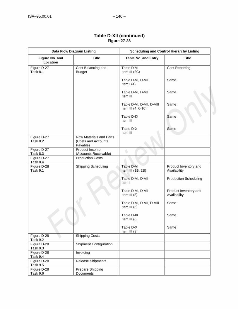
ISA–95.00.01 – 140 –
Table D-XII (continued)Figure 27-28
Data Flow Diagram Listing Scheduling and Control Hierarchy Listing
Figure No. andLocation
Title Table No. and Entry Title
Figure D-27Task 8.1
Cost Balancing andBudget
Table D-VIItem III (2C)
Table D-VI, D-VIIItem I (4)
Table D-VI, D-VIIItem III
Table D-VI, D-VII, D-VIIIItem III (4, 6-10)
Table D-IXItem III
Table D-XItem III
Cost Reporting
Same
Same
Same
Same
Same
Figure D-27Task 8.2
Raw Materials and Parts(Costs and AccountsPayable)
Figure D-27Task 8.3
Product Income(Accounts Receivable)
Figure D-27Task 8.4
Production Costs
Figure D-28Task 9.1
Shipping Scheduling Table D-VIItem III (1B, 2B)
Table D-VI, D-VIIItem I
Table D-VI, D-VIIItem III (8)
Table D-VI, D-VII, D-VIIIItem III (6)
Table D-IXItem III (6)
Table D-XItem III (3)
Product Inventory andAvailability
Production Scheduling
Product Inventory andAvailability
Same
Same
Same
Figure D-28Task 9.2
Shipping Costs
Figure D-28Task 9.3
Shipment Configuration
Figure D-28Task 9.4
Invoicing
Figure D-28Task 9.5
Release Shipments
Figure D-28Task 9.6
Prepare ShippingDocuments

– 141 – ISA–95.00.01–2000

ISA–95.00.01 – 142 –
Annex E (informative) — PRM correlation to MESA Internationalmodel and ISA-95.00.01-2000 models
The description of the scheduling and control hierarchy in the standard has been taken directly from thatdescribed in the Purdue Reference Model for CIM. As noted earlier, there are many such descriptions inthe literature, all somewhat different based on the viewpoints of the authors and the organizations theyrepresent.
One particularly popular description is that developed by MESA International, a consortium of vendorcompanies in the manufacturing control field. The publication, “MES Functionality and MRP to MES DataFlow Possibilities",12 develops and describes their listing of the functions at level 3. The MESAInternational listing of functions is presented below with a reference in each case to the correspondingfunction in the PRM.
E.1 Resource allocation and control
These functions are handled in the PRM by Function 3.0, Production Control, and in particular Functions3.2, Operations Control, and 3.3, Operations Planning. See clauses 6.3.2 and 6.3.3 and Table D-XI ofthe PRM.
E.2 Dispatching production
These functions would be handled in the PRM by “establishing the immediate production schedule,” asgiven in Item 5.1.2 here and by the same functions as listed under Item 5.2.1 above.
E.3 Data collection and acquisition
The PRM in Table D-IV, Item III, Plant Coordination and Operational Data Reporting, of annex D coversthis function. Its applicability in each level of the hierarchy is presented in Tables D-VI to D-X of the PRM.
E.4 Quality management
The PRM includes the Quality Assurance function in clause 6.6 of this standard and Item 6.0 andsubsidiary functions of Table D-XI and Figure D-25 of the PRM.
E.5 Process management
The PRM defines this function under its concept of Control Enforcement, the carrying out of productionscheduling and other upper-level directives by the control application functions of levels 1 and 2 of thehierarchy (Tables D-IX and D-X of the PRM).
Reporting of pertinent data on system and equipment status would be handled by Item III.4, “Service theman/machine interface,” of the above tables.
______
12 MESA International, MES Functionality and MRP to MES Data Flow Possibilities – White Paper Number 2 (1994)

– 143 – ISA–95.00.01–2000
E.6 Production planning and tracking
In the PRM this function is split between Item I, Production Scheduling, and Item III, System Coordinationand Operational Data Reporting, for levels 3 and lower of the hierarchical model. It is presented in Items2.0 and 3.0 of the Data-Flow Model and particularly Sub-Item 2.1, along with 3.2 and 3.3.
E.7 Performance analysis
It can be seen here that the PRM handles this functionality, like many others of MESA International,through a mixture of its stated functions. Here we consider Systems Coordination and Control (Item III ofTable D-IV and Tables VIII to X of the PRM); Control Enforcement (Item II); and System Reliability andAvailability Assurance (Item IV).
E.8 Operations and detailed scheduling
In terms of the PRM, this function would be considered a combination of most of the tasks from MESAInternational functions 5.2.1, Resource Allocation and Control, and 5.2.2, Dispatching Production, andwould involve those functions from the PRM listed in those locations.
E.9 Document control
In the PRM document control as described here is a combination of Plant Coordination and OperationalData Recording plus System Reliability and Available Assurance for document data collection and reportpreparation. It would involve Product Scheduling and Control Enforcement for document use to assurereliable plant operation. The corresponding data flow operations would be involved as well.
E.10 Labor management
While most personnel functions in the manufacturing plant involve human input and therefore would beconsidered external entities and thus external to the PRM and to this standard, those specificallymentioned in the MESA International function appear to all be automatable and thus would beencompassed in the hierarchical model function of Plant Coordination and Operational Data Reporting(Item III, Table D-IV and subsidiary listings in Tables D-VIII to D-X).
E.11 Maintenance management
Maintenance Management is carried out in the PRM through the hierarchical category of SystemReliability and Availability Assurance and by the Data Flow listing of Bubble 10.0, MaintenanceManagement (Bubble 3.2 in the original PRM listing).
E.12 ISA-95.00.01-2000 models
The ISA-95.00.01-2000 Equipment Hierarchy Model gives an application implementation flavor to thehierarchy model of the PRM that is itself strictly functional in nature. The present model is particularlyapplicable to larger plants as is ably illustrated by Figures D-5 to D-10 of annex D.
The PRM Figure D-4 has been modified to show a different split between the production scheduling andmanagement information systems and the control computation and control enforcement than in theoriginal publication. The split is now shown between level 3 and 4, based on planned changes to thePurdue model as a result of the analysis by the ISA SP95 committee.
Sub-Function 3.2 (Maintenance) in the PRM is included as a separate major function (10.0, Maintenance)in the ISA-95.00.01-2000 model. This is to simplify the representation of the level 3-4 split in thediscussion and associated figures.


Developing and promulgating sound consensus standards, recommended practices, and technicalreports is one of ISA’s primary goals. To achieve this goal the Standards and Practices Departmentrelies on the technical expertise and efforts of volunteer committee members, chairmen and reviewers.
ISA is an American National Standards Institute (ANSI) accredited organization. ISA administers UnitedStates Technical Advisory Groups (USTAGs) and provides secretariat support for InternationalElectrotechnical Commission (IEC) and International Organization for Standardization (ISO) committeesthat develop process measurement and control standards. To obtain additional information on theSociety’s standards program, please write:
ISAAttn: Standards Department67 Alexander DriveP.O. Box 12277Research Triangle Park, NC 27709
ISBN:
1-55617-727-5