Embed Size (px)
Citation preview
Enterprise Branch Security Design Guide
Americas HeadquartersCisco Systems, Inc.170 West Tasman DriveSan Jose, CA 95134-1706 USAhttp://www.cisco.comTel: 408 526-4000
800 553-NETS (6387)Fax: 408 527-0883
Customer Order Number: Text Part Number: OL-11726-01

ALL DESIGNS, SPECIFICATIONS, STATEMENTS, INFORMATION, AND RECOMMENDATIONS (COLLECTIVELY, "DESIGNS") IN THIS MANUAL ARE PRESENTED "AS IS," WITH ALL FAULTS. CISCO AND ITS SUPPLIERS DISCLAIM ALL WARRANTIES, INCLUDING, WITHOUT LIMITATION, THE WARRANTY OF MERCHANTABILITY, FITNESS FOR A PARTICULAR PURPOSE AND NONINFRINGEMENT OR ARISING FROM A COURSE OF DEALING, USAGE, OR TRADE PRACTICE. IN NO EVENT SHALL CISCO OR ITS SUPPLIERS BE LIABLE FOR ANY INDIRECT, SPECIAL, CONSEQUENTIAL, OR INCIDENTAL DAMAGES, INCLUDING, WITHOUT LIMITATION, LOST PROFITS OR LOSS OR DAMAGE TO DATA ARISING OUT OF THE USE OR INABILITY TO USE THE DESIGNS, EVEN IF CISCO OR ITS SUPPLIERS HAVE BEEN ADVISED OF THE POSSIBILITY OF SUCH DAMAGES.
THE DESIGNS ARE SUBJECT TO CHANGE WITHOUT NOTICE. USERS ARE SOLELY RESPONSIBLE FOR THEIR APPLICATION OF THE DESIGNS. THE DESIGNS DO NOT CONSTITUTE THE TECHNICAL OR OTHER PROFESSIONAL ADVICE OF CISCO, ITS SUPPLIERS OR PARTNERS. USERS SHOULD CONSULT THEIR OWN TECHNICAL ADVISORS BEFORE IMPLEMENTING THE DESIGNS. RESULTS MAY VARY DEPENDING ON FACTORS NOT TESTED BY CISCO.
CCVP, the Cisco Logo, and the Cisco Square Bridge logo are trademarks of Cisco Systems, Inc.; Changing the Way We Work, Live, Play, and Learn is a service mark of Cisco Systems, Inc.; and Access Registrar, Aironet, BPX, Catalyst, CCDA, CCDP, CCIE, CCIP, CCNA, CCNP, CCSP, Cisco, the Cisco Certified Internetwork Expert logo, Cisco IOS, Cisco Press, Cisco Systems, Cisco Systems Capital, the Cisco Systems logo, Cisco Unity, Enterprise/Solver, EtherChannel, EtherFast, EtherSwitch, Fast Step, Follow Me Browsing, FormShare, GigaDrive, GigaStack, HomeLink, Internet Quotient, IOS, iPhone, IP/TV, iQ Expertise, the iQ logo, iQ Net Readiness Scorecard, iQuick Study, LightStream, Linksys, MeetingPlace, MGX, Networking Academy, Network Registrar, Packet, PIX, ProConnect, RateMUX, ScriptShare, SlideCast, SMARTnet, StackWise, The Fastest Way to Increase Your Internet Quotient, and TransPath are registered trademarks of Cisco Systems, Inc. and/or its affiliates in the United States and certain other countries.
All other trademarks mentioned in this document or Website are the property of their respective owners. The use of the word partner does not imply a partnership relationship between Cisco and any other company. (0612R)
Enterprise Branch Security Design Guide © 2007 Cisco Systems, Inc. All rights reserved.
OL-11726-01
C O N T E N T S
Introduction 1
Design Overview 2
Design Components 3Single-Tier Branch Profile 4Dual-Tier Branch Profile 5Multi-Tier Branch Profile 6Design Component Summary 7
Design and Implementation 8WAN Services 8
Internet Deployment Model 9Private WAN Deployment Model 10
MPLS Deployment Model 10
LAN Services 11
Network Fundamentals 13
High Availability 13
IP Addressing and IP Routing 15
Quality of Service 17
Security Services 19
Infrastructure Protection 19
Secure Connectivity 20
Threat Defense Detection and Mitigation 21
Configuration and Implementation 24
WAN Services 27
Single-Tier Branch Profile 28
Dual-Tier Branch Profile 29
Multi-Tier Branch Profile 29
LAN Services 30
Single-Tier Branch Profile 30
Dual-Tier Branch Profile 31
Multi-Tier Branch Profile 33
Network Fundamental Services 36
Single-Tier Branch 36
Dual-Tier Profile 39
Multi-Tier Profile 42
Quality of Service 48
iEnterprise Branch Security Design Guide
Contents
Single-Tier Profile 55
Dual-Tier Profile 55
Multi-Tier Profile 56
Security Services 57
Infrastructure Protection 57
Secure Connectivity 62
Threat Defense Detection and Mitigation 65
Summary 84
Appendix A—Cisco Platforms Evaluated 85
Appendix B—Cisco IOS Releases Evaluated 85
Appendix C—Configurations 86
Single-Tier Profile 86
Access Router Configuration 86
Internal Switch Configuration 95
Dual-Tier Branch Profile 99
Access Router #1 Configuration 99
Access Router #2 Configuration 105
External Switch Configuration 110
Multi-Tier Branch Profile 115
WAN Router #1 Configuration 115
WAN Router #2 Configuration 120
ASA Firewall Configuration 124
Access Router #1 Configuration 126
Access Router #2 Configuration 131
Stackwise Switch Master Configuration 135
Appendix D—References and Recommended Reading 139
Appendix E—Acronyms 140
iiEnterprise Branch Security Design Guide
OL-11726-01
Enterprise Branch Security Design Guide
This design chapter offers guidelines and best practices for securing the enterprise branch. The following three branch profiles are described to address various customer requirements balancing cost, security, availability, and manageability:
• Single-tier
• Dual-tier
• Multi-tier
In each profile, the concepts of high availability, infrastructure protection, secure connectivity, and threat defense are addressed. This chapter lays the foundation for integration of advanced services into the enterprise branch architecture.
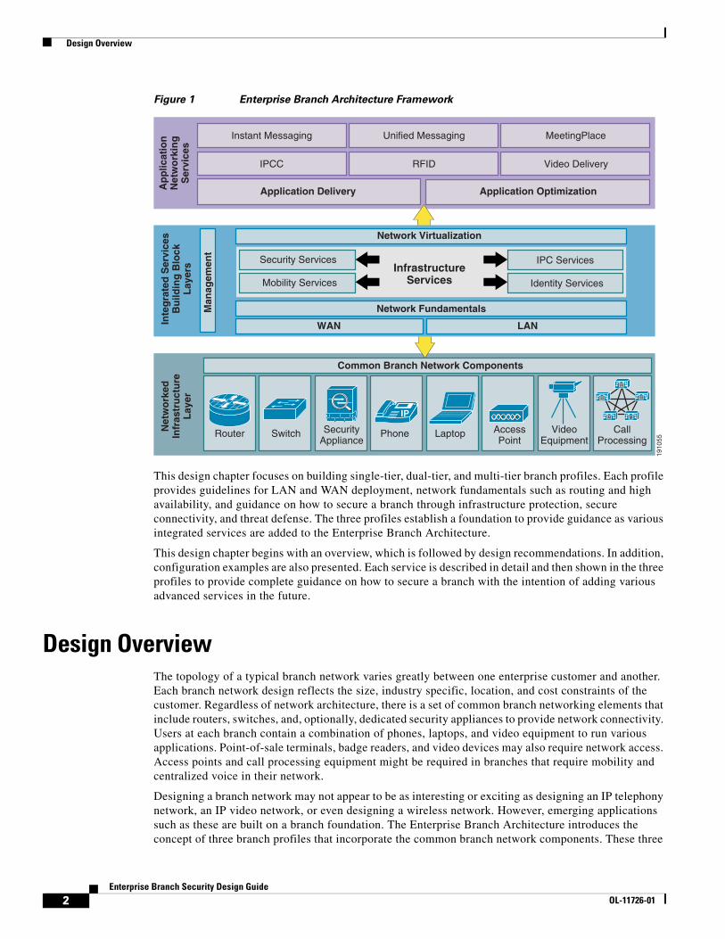
IntroductionThis design chapter evaluates securing an enterprise branch as it pertains to the Enterprise Branch Architecture framework. The Enterprise Branch Architecture is one component in the overall Cisco Service Oriented Network Architecture (SONA) that provides guidelines to accelerate applications, business processes, and profitability. Based on the Cisco SONA framework, the Enterprise Branch Architecture incorporates networked infrastructure services, integrated services, and application networking services across typical branch networks, as shown in Figure 1.
Americas Headquarters:
© 2007 Cisco Systems, Inc. All rights reserved.
Cisco Systems, Inc., 170 West Tasman Drive, San Jose, CA 95134-1706 USA
Design Overview
Figure 1 Enterprise Branch Architecture Framework
This design chapter focuses on building single-tier, dual-tier, and multi-tier branch profiles. Each profile provides guidelines for LAN and WAN deployment, network fundamentals such as routing and high availability, and guidance on how to secure a branch through infrastructure protection, secure connectivity, and threat defense. The three profiles establish a foundation to provide guidance as various integrated services are added to the Enterprise Branch Architecture.
This design chapter begins with an overview, which is followed by design recommendations. In addition, configuration examples are also presented. Each service is described in detail and then shown in the three profiles to provide complete guidance on how to secure a branch with the intention of adding various advanced services in the future.
Design OverviewThe topology of a typical branch network varies greatly between one enterprise customer and another. Each branch network design reflects the size, industry specific, location, and cost constraints of the customer. Regardless of network architecture, there is a set of common branch networking elements that include routers, switches, and, optionally, dedicated security appliances to provide network connectivity. Users at each branch contain a combination of phones, laptops, and video equipment to run various applications. Point-of-sale terminals, badge readers, and video devices may also require network access. Access points and call processing equipment might be required in branches that require mobility and centralized voice in their network.
Designing a branch network may not appear to be as interesting or exciting as designing an IP telephony network, an IP video network, or even designing a wireless network. However, emerging applications such as these are built on a branch foundation. The Enterprise Branch Architecture introduces the concept of three branch profiles that incorporate the common branch network components. These three
1910
55
MeetingPlace
IPCC RFID Video Delivery
Application Delivery
Security Services
Mobility Services Identity Services
InfrastructureServices
WAN
Unified Messaging
Ap
plic
atio
nN
etw
ork
ing
Ser
vice
s
Inte
gra
ted
Ser
vice
s B
uild
ing
Blo
ck
Lay
ers
Net
wo
rked
Infr
astr
uct
ure
Lay
er
Instant Messaging
Application Optimization
Network Fundamentals
Network Virtualization
IPC Services
Man
agem
ent
Common Branch Network Components
LAN
IP
CallProcessing
M
M
M M
M
Router Switch SecurityAppliance
Phone Laptop AccessPoint
VideoEquipment
2Enterprise Branch Security Design Guide
OL-11726-01
Design Components
profiles are not intended to be the only architectures recommended for branch networks, but rather a representation of various aspects branch networks need to include. These profiles are used as the baseline foundation in which all the integrated services building blocks and application networking services are built. This design chapter builds the foundation through the three profiles.
This design chapter provides an overview of the three profiles tested. The profile approach is meant to provide guidance for using several network architectures to allow the reader to mix and match between profiles without having to test every single branch architecture available. The following fundamental services are provided in this chapter:
• LAN deployment model
• WAN deployment model
• Network fundamentals (high availability, IP addressing and routing, and QoS)
• Security services (infrastructure protection, secure connectivity, and threat defense)
As each service is defined in detail, the implementation of each service in each profile is discussed. In the end, the three profiles provide guidance on how to secure a branch with high availability using the common branch networking components.
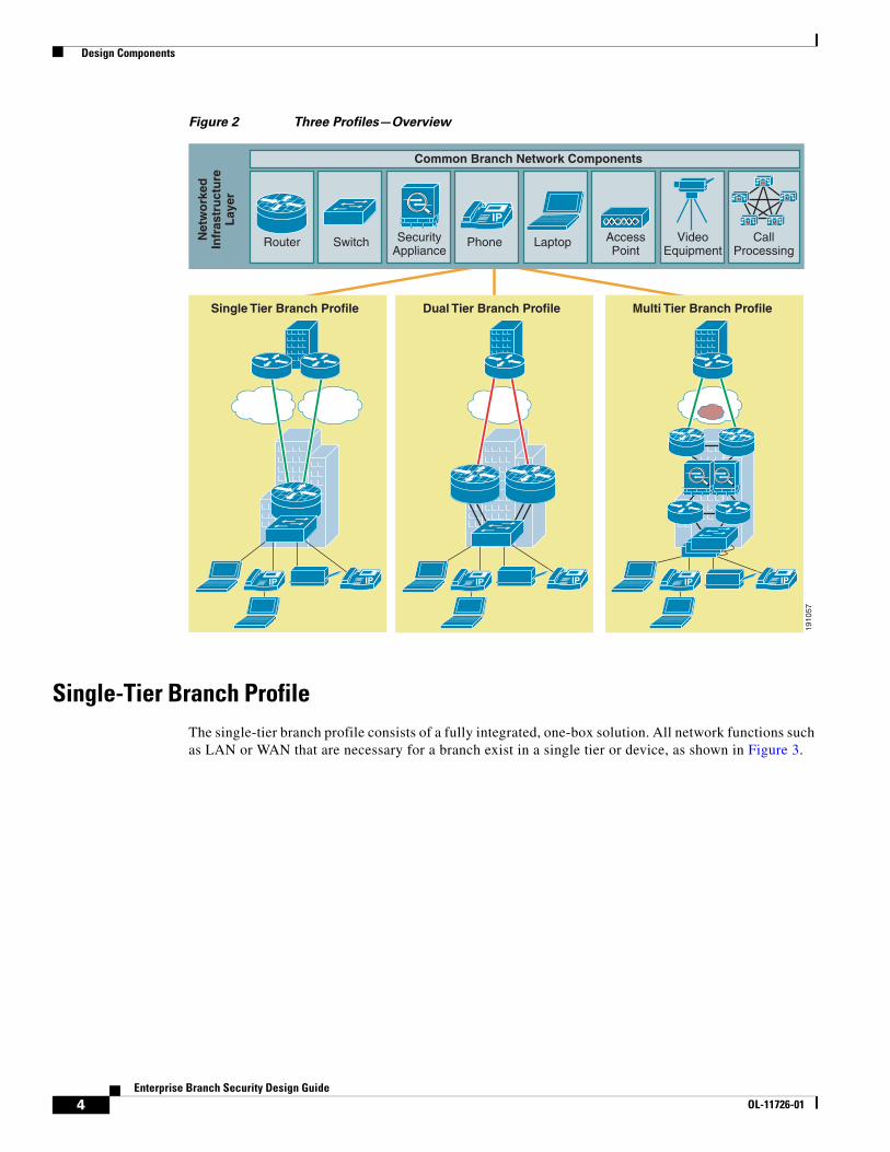
Design ComponentsThe design components for this design chapter comprise the networked infrastructure layer of the overall Enterprise Branch Architecture Framework. From the common network elements, three profiles are presented. The three profiles tested are the single-tier, dual-tier, and multi-tier branch profiles, as shown in Figure 2. Each profile is discussed in greater detail in the following sections.
3Enterprise Branch Security Design Guide
OL-11726-01
Design Components
Figure 2 Three Profiles—Overview
Single-Tier Branch ProfileThe single-tier branch profile consists of a fully integrated, one-box solution. All network functions such as LAN or WAN that are necessary for a branch exist in a single tier or device, as shown in Figure 3.
1910
57
Net
wo
rked
Infr
astr
uct
ure
Lay
er
Common Branch Network Components
IP
CallProcessing
M
M
M M
M
Router Switch SecurityAppliance
Phone Laptop AccessPoint
VideoEquipment
IP IP
Single Tier Branch Profile
IP IP
Dual Tier Branch Profile
IP IP
Multi Tier Branch Profile
4Enterprise Branch Security Design Guide
OL-11726-01
Design Components
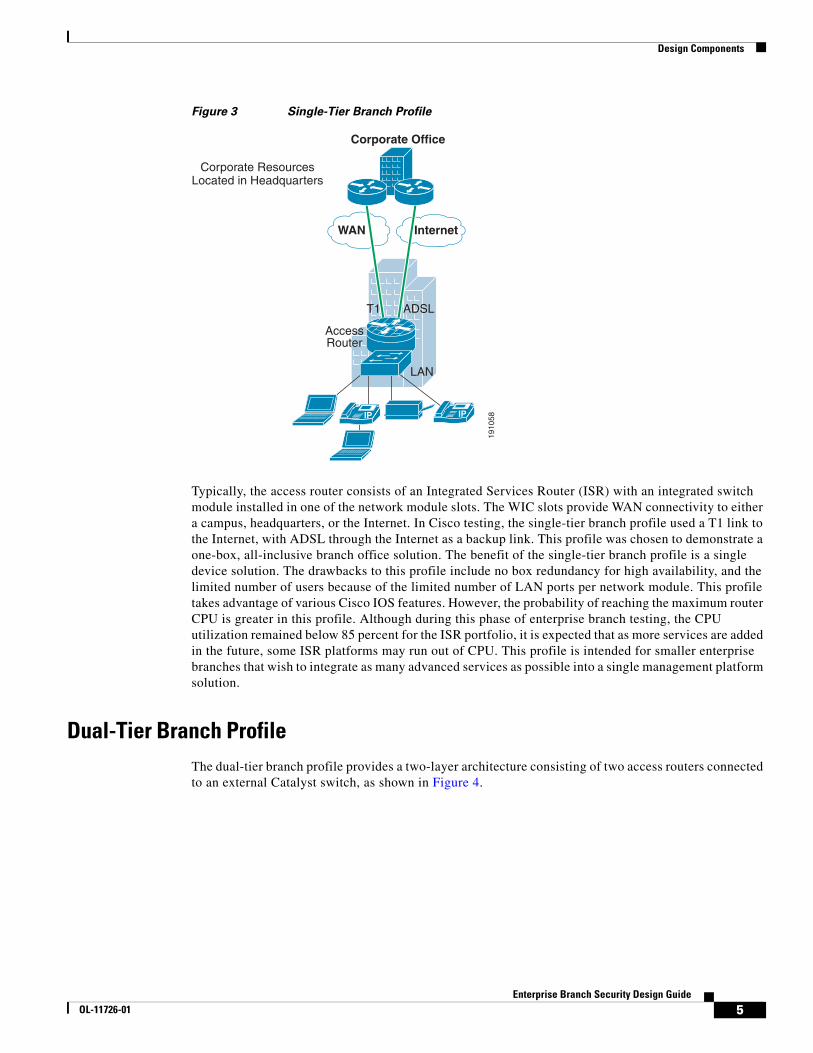
Figure 3 Single-Tier Branch Profile
Typically, the access router consists of an Integrated Services Router (ISR) with an integrated switch module installed in one of the network module slots. The WIC slots provide WAN connectivity to either a campus, headquarters, or the Internet. In Cisco testing, the single-tier branch profile used a T1 link to the Internet, with ADSL through the Internet as a backup link. This profile was chosen to demonstrate a one-box, all-inclusive branch office solution. The benefit of the single-tier branch profile is a single device solution. The drawbacks to this profile include no box redundancy for high availability, and the limited number of users because of the limited number of LAN ports per network module. This profile takes advantage of various Cisco IOS features. However, the probability of reaching the maximum router CPU is greater in this profile. Although during this phase of enterprise branch testing, the CPU utilization remained below 85 percent for the ISR portfolio, it is expected that as more services are added in the future, some ISR platforms may run out of CPU. This profile is intended for smaller enterprise branches that wish to integrate as many advanced services as possible into a single management platform solution.
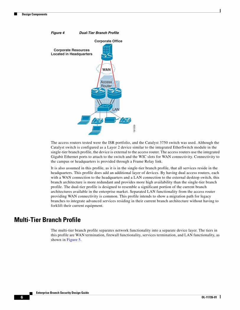
Dual-Tier Branch ProfileThe dual-tier branch profile provides a two-layer architecture consisting of two access routers connected to an external Catalyst switch, as shown in Figure 4.
1910
58IP IP
WAN Internet
Corporate Office
T1 ADSL
LAN
Corporate ResourcesLocated in Headquarters
AccessRouter
5Enterprise Branch Security Design Guide
OL-11726-01
Design Components
Figure 4 Dual-Tier Branch Profile
The access routers tested were the ISR portfolio, and the Catalyst 3750 switch was used. Although the Catalyst switch is configured as a Layer 2 device similar to the integrated EtherSwitch module in the single-tier branch profile, the device is external to the access router. The access routers use the integrated Gigabit Ethernet ports to attach to the switch and the WIC slots for WAN connectivity. Connectivity to the campus or headquarters is provided through a Frame Relay link.
It is also assumed in this profile, as it is in the single-tier branch profile, that all services reside in the headquarters. This profile does add an additional layer of devices. By having dual access routers, each with a WAN connection to the headquarters and a LAN connection to the external desktop switch, this branch architecture is more redundant and provides more high availability than the single-tier branch profile. The dual-tier profile is designed to resemble a significant portion of the current branch architectures available in the enterprise market. Separated LAN functionality from the access router providing WAN connectivity is common. This profile intends to show a migration path for legacy branches to integrate advanced services residing in their current branch architecture without having to forklift their current equipment.
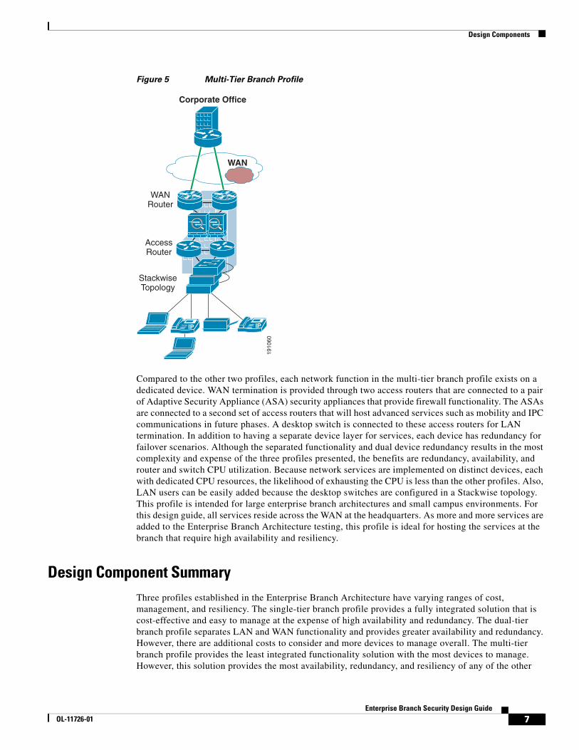
Multi-Tier Branch ProfileThe multi-tier branch profile separates network functionality into a separate device layer. The tiers in this profile are WAN termination, firewall functionality, services termination, and LAN functionality, as shown in Figure 5.
1910
59
IP IP
Corporate ResourcesLocated in Headquarters
AccessRouter
LAN
WAN
Corporate Office
6Enterprise Branch Security Design Guide
OL-11726-01
Design Components
Figure 5 Multi-Tier Branch Profile
Compared to the other two profiles, each network function in the multi-tier branch profile exists on a dedicated device. WAN termination is provided through two access routers that are connected to a pair of Adaptive Security Appliance (ASA) security appliances that provide firewall functionality. The ASAs are connected to a second set of access routers that will host advanced services such as mobility and IPC communications in future phases. A desktop switch is connected to these access routers for LAN termination. In addition to having a separate device layer for services, each device has redundancy for failover scenarios. Although the separated functionality and dual device redundancy results in the most complexity and expense of the three profiles presented, the benefits are redundancy, availability, and router and switch CPU utilization. Because network services are implemented on distinct devices, each with dedicated CPU resources, the likelihood of exhausting the CPU is less than the other profiles. Also, LAN users can be easily added because the desktop switches are configured in a Stackwise topology. This profile is intended for large enterprise branch architectures and small campus environments. For this design guide, all services reside across the WAN at the headquarters. As more and more services are added to the Enterprise Branch Architecture testing, this profile is ideal for hosting the services at the branch that require high availability and resiliency.
Design Component SummaryThree profiles established in the Enterprise Branch Architecture have varying ranges of cost, management, and resiliency. The single-tier branch profile provides a fully integrated solution that is cost-effective and easy to manage at the expense of high availability and redundancy. The dual-tier branch profile separates LAN and WAN functionality and provides greater availability and redundancy. However, there are additional costs to consider and more devices to manage overall. The multi-tier branch profile provides the least integrated functionality solution with the most devices to manage. However, this solution provides the most availability, redundancy, and resiliency of any of the other
1910
60
AccessRouter
Corporate Office
WANRouter
IP IP
WAN
StackwiseTopology
7Enterprise Branch Security Design Guide
OL-11726-01
Design and Implementation
profiles. The testing results of all three profiles are included in this design chapter to provide a template for a specific customer branch architecture. It is fully expected that many branch architectures will contain some parts of each profile presented. This design chapter is organized to address each network service individually. Under each section for a specific network service, all three profiles are presented, and guidance for each of the three scenarios is provided. The profile approach for each individual network service offers the most flexibility and modularity to provide the most guidance for integrating advanced services into most types of required branch architecture.
Design and ImplementationThis section addresses each of the three profiles described in Design Components, page 3, using several of the integrated services building blocks as described in the overall Enterprise Branch Architecture. This section discusses the following services:
• WAN services
• LAN services
• Network fundamentals
• Security services
Each service building block is described as it applies to each profile, and specific implementation issues for each service and profile are discussed.
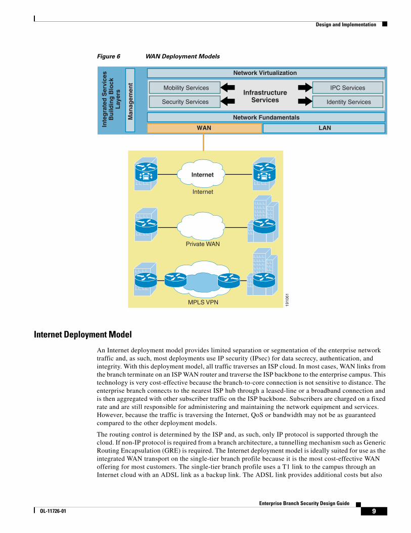
WAN ServicesWAN services provide the foundation for the Enterprise Branch Architecture to connect to the campus or data center core using an Internet service provider (ISP), a traditional service provider network, private leased lines, or some combination of these technologies. The branch may also obtain Internet access directly (split tunnel) without first accessing the campus core. The WAN services building block consists of the following three fundamental deployment options, each with its own set of associated attributes, as shown in Figure 6:
• Internet deployment model
• Private WAN deployment model
• MPLS deployment model
The set of attributes associated with each profile influences the use of specific features, and requires specific considerations when designing a branch office. Each of the three profiles address a separate WAN deployment model.
8Enterprise Branch Security Design Guide
OL-11726-01
Design and Implementation
Figure 6 WAN Deployment Models
Internet Deployment Model
An Internet deployment model provides limited separation or segmentation of the enterprise network traffic and, as such, most deployments use IP security (IPsec) for data secrecy, authentication, and integrity. With this deployment model, all traffic traverses an ISP cloud. In most cases, WAN links from the branch terminate on an ISP WAN router and traverse the ISP backbone to the enterprise campus. This technology is very cost-effective because the branch-to-core connection is not sensitive to distance. The enterprise branch connects to the nearest ISP hub through a leased-line or a broadband connection and is then aggregated with other subscriber traffic on the ISP backbone. Subscribers are charged on a fixed rate and are still responsible for administering and maintaining the network equipment and services. However, because the traffic is traversing the Internet, QoS or bandwidth may not be as guaranteed compared to the other deployment models.
The routing control is determined by the ISP and, as such, only IP protocol is supported through the cloud. If non-IP protocol is required from a branch architecture, a tunnelling mechanism such as Generic Routing Encapsulation (GRE) is required. The Internet deployment model is ideally suited for use as the integrated WAN transport on the single-tier branch profile because it is the most cost-effective WAN offering for most customers. The single-tier branch profile uses a T1 link to the campus through an Internet cloud with an ADSL link as a backup link. The ADSL link provides additional costs but also
1910
61
Internet
Internet
Private WAN
MPLS VPN
Security Services
Mobility Services
Identity Services
InfrastructureServices
WANInte
gra
ted
Ser
vice
s B
uild
ing
Blo
ck
Lay
ers
Network Fundamentals
Network Virtualization
IPC Services
Man
agem
ent
LAN
9Enterprise Branch Security Design Guide
OL-11726-01
Design and Implementation
provides some form of failover recovery. The ADSL link can be left out of this profile if cost is more important than increased availability. Traffic from the single-tier branch profile is encrypted, and non-IP traffic is tunnelled to the enterprise WAN edge. The mechanism to secure traffic is addressed in Secure Connectivity, page 20. An advantage to the Internet deployment model is that future branch architectures can communicate in an any-to-any inter-site connection, full-mesh topology. However, when considering adding latency and jitter-sensitive services such as voice or video, additional consideration must be taken because the Internet cloud can guarantee latency and QoS, in some instances such as those found in V3PN networks, but at perhaps additional costs, and only from select service providers.
Private WAN Deployment Model
The private WAN deployment model is the traditional hub-and-spoke model that has been deployed in enterprise networks for decades. Traditional Frame Relay or ATM networks are categorized in this deployment model. Data privacy is provided through traffic separation such as Frame Relay data-link connection identifiers (DLCIs) or ATM virtual circuits (VCs). Routing is controlled by the enterprise core network, and both IP and non-IP protocols are supported. No encryption or tunnelling mechanism is required because connectivity is provided at Layer 2, but can be used depending on the exact branch requirements of the customer.
The dual-tier branch profile uses a Frame Relay private WAN deployment model. Each access router has been provisioned to contain a single Frame Relay link to the enterprise WAN edge via a point-to-point T1 link. Separate DLCIs are configured to provide data privacy within the branch and through the external branch cloud. The majority of Frame Relay networks deployed are provisioned by service providers for data transmission services. Frame Relay is implemented in both public carrier-provided networks and in private enterprise networks. In public carrier-provided Frame Relay networks, the Frame Relay switching equipment is located in the central offices of a telecommunications carrier. Subscribers are charged based on their network use but are relieved from administering and maintaining the Frame Relay network equipment and services. In private Frame Relay networks, the administration and maintenance of the network are the responsibilities of the enterprise. All the equipment, including the switching equipment, is owned by the customer. The actual implementation of a Frame Relay network is the same regardless of being public or private; however, the cost and ownership are factors.
MPLS Deployment Model
The MPLS deployment model provides the following beneficial applications: MPLS virtual private network (VPN), traffic engineering, and QoS. MPLS is a packet-forwarding technology that uses labels to make data forwarding decisions. MPLS label forwarding is performed with a label lookup for an incoming label, which is then swapped with the outgoing label and finally sent to the next hop. Labels are imposed on the packets only once at the edge of the MPLS network, and removed at the other end to provide data privacy across the MPLS network. Traffic engineering is enabled through MPLS mechanisms that allow traffic to be directed through a specific path, which may not necessarily be the least expensive path in terms of routing protocol metrics. QoS techniques are implemented to ensure that latency-sensitive traffic types are given priority over less important traffic in transit of the network. QoS gives the network administrator the capability to ensure that VoIP or video latency requirements are met. Only IP traffic traverses an MPLS cloud, so a tunnelling mechanism is required for non-IP traffic. The design intent of the multi-tier branch profile is high availability and resiliency. The MPLS deployment model was chosen based on the benefits the MPLS technology provides compared to the other deployment models. Many enterprise customers are connecting with two MPLS service providers at the branch and head-end campus to isolate themselves from the failure of a single MPLS network.
10Enterprise Branch Security Design Guide
OL-11726-01
Design and Implementation
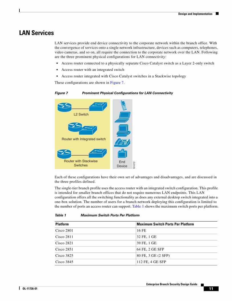
LAN ServicesLAN services provide end device connectivity to the corporate network within the branch office. With the convergence of services onto a single network infrastructure, devices such as computers, telephones, video cameras, and so on, all require the connection to the corporate network over the LAN. Following are the three prominent physical configurations for LAN connectivity:
• Access router connected to a physically separate Cisco Catalyst switch as a Layer 2-only switch
• Access router with an integrated switch
• Access router integrated with Cisco Catalyst switches in a Stackwise topology
These configurations are shown in Figure 7.
Figure 7 Prominent Physical Configurations for LAN Connectivity
Each of these configurations have their own set of advantages and disadvantages, and are discussed in the three profiles defined.
The single-tier branch profile uses the access router with an integrated switch configuration. This profile is intended for smaller branch offices that do not require numerous LAN endpoints. This LAN configuration offers all the switching functionality as does any external desktop switch integrated into a one-box solution. The number of users for a branch network deploying this configuration is limited to the number of ports an access router can support. Table 1 shows the maximum switch ports per platform.
1910
72
L2 Switch
IPRouter with Integrated switch
EndDevice
Router with StackwiseSwitches
Table 1 Maximum Switch Ports Per Platform
Platform Maximum Switch Ports Per Platform
Cisco 2801 16 FE
Cisco 2811 32 FE, 1 GE
Cisco 2821 39 FE, 1 GE
Cisco 2851 64 FE, 2 GE SFP
Cisco 3825 80 FE, 3 GE (2 SFP)
Cisco 3845 112 FE, 4 GE SFP
11Enterprise Branch Security Design Guide
OL-11726-01
Design and Implementation
In the single-tier branch profile, the integrated switch is configured as a Layer 2 device using the internal backplane connector as the trunk port to the access router. VLANs are configured for data privacy, but only one IP address is required with the switch as a Layer 2-only device. Inline power is supported in this configuration and full Cisco Catalyst features are supported. The advantage to this design is a one-box solution, which means lower total cost of ownership and a single device for management. The disadvantage is the limited number of ports.
The dual-tier branch profile uses the access router connected to a physically separate Cisco Catalyst switch as a Layer 2-only switch. This LAN configuration in terms of feature parity is the same as the configuration used in the single-tier branch profile. The only differences are that the switch is a separate device, and a cable attaching the access router and the switch is required. This cable can be configured as an EtherChannel or a trunk. In the dual-tier branch profile, the connection to the access router is via a trunk port. Spanning tree does not need to be enabled in this profile to avoid loops because there are only two trunk ports to the access router from the external switch. Inline power is provided, depending on the model of the switch chosen. Additional switchports can be added easily, or a larger switch chassis can be used. The disadvantages to this LAN configuration are an additional device to manage and additional costs of purchasing a separate device. This LAN configuration was chosen for the dual-tier branch profile to provide an additional tier of hardware for each network function, and for medium-size branch deployments where more users are required than the fully integrated configuration without the complexity of the Layer 3 services provided by an external Cisco Catalyst switch. However, if Layer 3 services are eventually needed, the equipment is already in place to provide the most flexibility for future growth.
The access router integrated with Cisco Catalyst switches in a Stackwise technology configuration is leveraged in the multi-tier branch profile. Cisco Stackwise technology provides a method of collectively using the capabilities of a stack of switches. The switches are united into a single logical unit via special stack interconnect cables that create a bi-directional closed-loop path. The stack behaves as a single switching unit that is managed by a master switch elected from one of the member switches. The master switch automatically creates and updates all the switching and routing tables. A working stack can accept new members or delete ones without service interruption. Because of the lack of service interruptions provided by the closed loop created in the stack, this LAN configuration is ideally suited for the multi-tier branch profile. The multi-tier branch profile is mainly focused on availability and resiliency, and the Stackwise technology provides this benefit. The Cisco Catalyst switches chosen are configured as Layer 3 devices. Routing decisions are therefore made in the switches. Inline power is provided depending on the exact Cisco Catalyst switch model chosen. The advantages to this design are high availability and resiliency as well as the ability to add more users without service interruption. The disadvantage of this configuration is that the total amount of devices to manage increases as well as the cost of each additional device.
As with the WAN deployment models, the LAN configurations chosen for each profile are not meant to be the only configurations possible. Each profile can interchange any of the LAN configurations. The LAN configurations chosen for this design chapter for each profile is meant for guidance, but can be deployed in any profile depending on the exact customer requirements. For more in-depth LAN deployment options as they refer to generic LAN designs rather than a profile approach, see the following URL: http://www.cisco.com/go/srnd
For further details, see the following URLs:
• LAN Baseline Architecture Overview—Branch Office Network http://www.cisco.com/univercd/cc/td/doc/solution/lanovext.pdf
• LAN Baseline Architecture Branch Office Network Reference Design Guide http://www.cisco.com/univercd/cc/td/doc/solution/lanovext.pdf
12Enterprise Branch Security Design Guide
OL-11726-01
Design and Implementation
Network FundamentalsNetwork fundamentals refer to the basic services that are required for network connectivity. These services include high availability, IP addressing and IP routing, and QoS. Regardless of which WAN or LAN deployment model is chosen for a branch architecture, network fundamentals are required to provide a foundation for any service to be overlaid onto the branch network.
High Availability
High availability is crucial for modern branch architectures. Remaining productive during a network failure is extremely important for all aspects of a network, and especially for branch networks. There are several aspects of high availability, and the three profiles address each one.
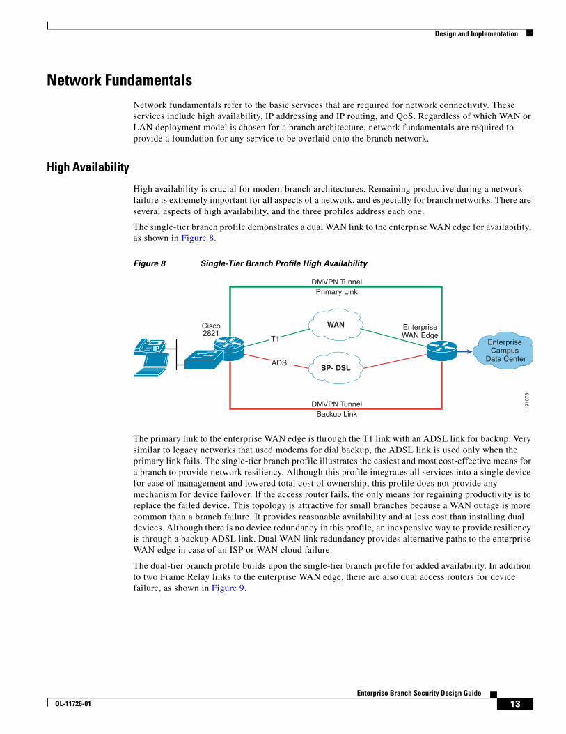
The single-tier branch profile demonstrates a dual WAN link to the enterprise WAN edge for availability, as shown in Figure 8.
Figure 8 Single-Tier Branch Profile High Availability
The primary link to the enterprise WAN edge is through the T1 link with an ADSL link for backup. Very similar to legacy networks that used modems for dial backup, the ADSL link is used only when the primary link fails. The single-tier branch profile illustrates the easiest and most cost-effective means for a branch to provide network resiliency. Although this profile integrates all services into a single device for ease of management and lowered total cost of ownership, this profile does not provide any mechanism for device failover. If the access router fails, the only means for regaining productivity is to replace the failed device. This topology is attractive for small branches because a WAN outage is more common than a branch failure. It provides reasonable availability and at less cost than installing dual devices. Although there is no device redundancy in this profile, an inexpensive way to provide resiliency is through a backup ADSL link. Dual WAN link redundancy provides alternative paths to the enterprise WAN edge in case of an ISP or WAN cloud failure.
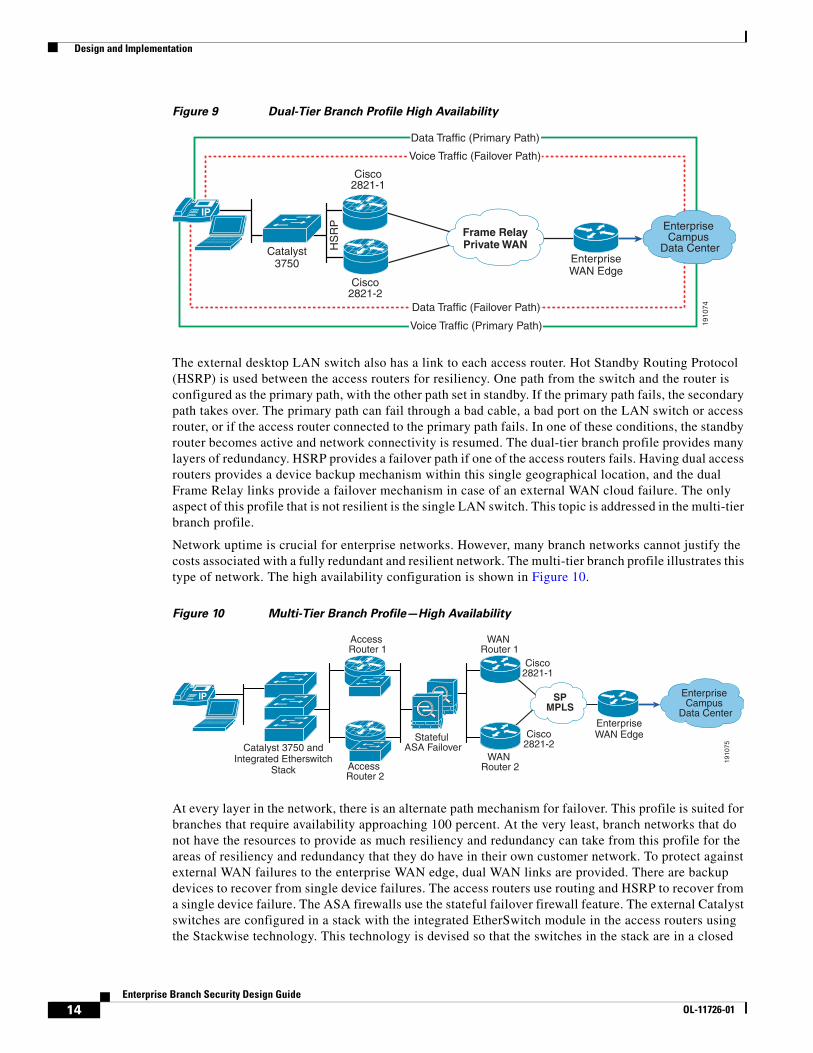
The dual-tier branch profile builds upon the single-tier branch profile for added availability. In addition to two Frame Relay links to the enterprise WAN edge, there are also dual access routers for device failure, as shown in Figure 9.
1910
73
IP
DMVPN TunnelPrimary Link
WAN
SP- DSL
DMVPN TunnelBackup Link
EnterpriseWAN Edge
Enterprise Campus
Data Center
Cisco2821
T1
ADSL
13Enterprise Branch Security Design Guide
OL-11726-01
Design and Implementation
Figure 9 Dual-Tier Branch Profile High Availability
The external desktop LAN switch also has a link to each access router. Hot Standby Routing Protocol (HSRP) is used between the access routers for resiliency. One path from the switch and the router is configured as the primary path, with the other path set in standby. If the primary path fails, the secondary path takes over. The primary path can fail through a bad cable, a bad port on the LAN switch or access router, or if the access router connected to the primary path fails. In one of these conditions, the standby router becomes active and network connectivity is resumed. The dual-tier branch profile provides many layers of redundancy. HSRP provides a failover path if one of the access routers fails. Having dual access routers provides a device backup mechanism within this single geographical location, and the dual Frame Relay links provide a failover mechanism in case of an external WAN cloud failure. The only aspect of this profile that is not resilient is the single LAN switch. This topic is addressed in the multi-tier branch profile.
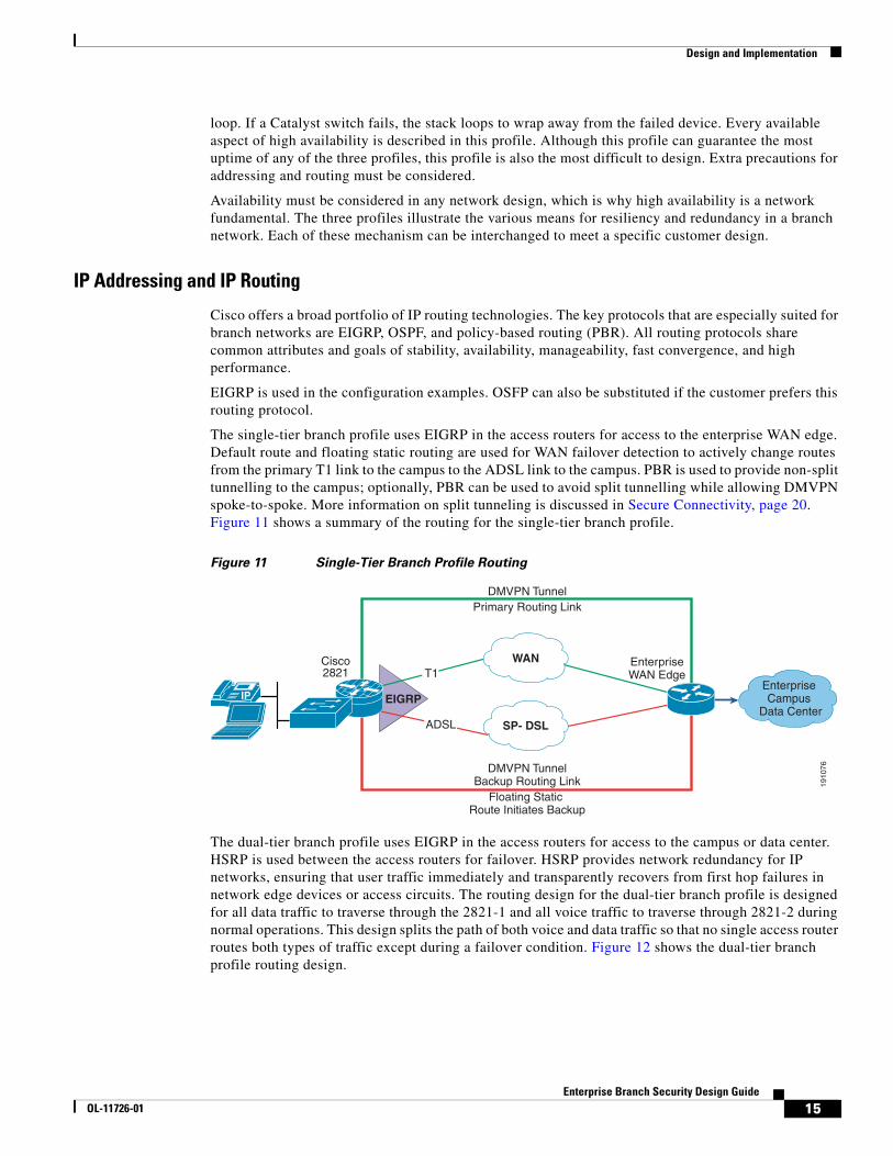
Network uptime is crucial for enterprise networks. However, many branch networks cannot justify the costs associated with a fully redundant and resilient network. The multi-tier branch profile illustrates this type of network. The high availability configuration is shown in Figure 10.
Figure 10 Multi-Tier Branch Profile—High Availability
At every layer in the network, there is an alternate path mechanism for failover. This profile is suited for branches that require availability approaching 100 percent. At the very least, branch networks that do not have the resources to provide as much resiliency and redundancy can take from this profile for the areas of resiliency and redundancy that they do have in their own customer network. To protect against external WAN failures to the enterprise WAN edge, dual WAN links are provided. There are backup devices to recover from single device failures. The access routers use routing and HSRP to recover from a single device failure. The ASA firewalls use the stateful failover firewall feature. The external Catalyst switches are configured in a stack with the integrated EtherSwitch module in the access routers using the Stackwise technology. This technology is devised so that the switches in the stack are in a closed
1910
74
Catalyst3750
IP
Frame RelayPrivate WAN
EnterpriseWAN Edge
Enterprise Campus
Data Center
Cisco2821-1
Cisco2821-2
HS
RP
Data Traffic (Failover Path)
Voice Traffic (Primary Path)
Data Traffic (Primary Path)
Voice Traffic (Failover Path)
1910
75Catalyst 3750 andIntegrated Etherswitch
Stack
IP SPMPLS
EnterpriseWAN Edge
Enterprise Campus
Data Center
Access Router 1
Access Router 2
Stateful ASA Failover
WAN Router 1
WAN Router 2
Cisco2821-1
Cisco2821-2
14Enterprise Branch Security Design Guide
OL-11726-01
Design and Implementation
loop. If a Catalyst switch fails, the stack loops to wrap away from the failed device. Every available aspect of high availability is described in this profile. Although this profile can guarantee the most uptime of any of the three profiles, this profile is also the most difficult to design. Extra precautions for addressing and routing must be considered.
Availability must be considered in any network design, which is why high availability is a network fundamental. The three profiles illustrate the various means for resiliency and redundancy in a branch network. Each of these mechanism can be interchanged to meet a specific customer design.
IP Addressing and IP Routing
Cisco offers a broad portfolio of IP routing technologies. The key protocols that are especially suited for branch networks are EIGRP, OSPF, and policy-based routing (PBR). All routing protocols share common attributes and goals of stability, availability, manageability, fast convergence, and high performance.
EIGRP is used in the configuration examples. OSFP can also be substituted if the customer prefers this routing protocol.
The single-tier branch profile uses EIGRP in the access routers for access to the enterprise WAN edge. Default route and floating static routing are used for WAN failover detection to actively change routes from the primary T1 link to the campus to the ADSL link to the campus. PBR is used to provide non-split tunnelling to the campus; optionally, PBR can be used to avoid split tunnelling while allowing DMVPN spoke-to-spoke. More information on split tunneling is discussed in Secure Connectivity, page 20. Figure 11 shows a summary of the routing for the single-tier branch profile.
Figure 11 Single-Tier Branch Profile Routing
The dual-tier branch profile uses EIGRP in the access routers for access to the campus or data center. HSRP is used between the access routers for failover. HSRP provides network redundancy for IP networks, ensuring that user traffic immediately and transparently recovers from first hop failures in network edge devices or access circuits. The routing design for the dual-tier branch profile is designed for all data traffic to traverse through the 2821-1 and all voice traffic to traverse through 2821-2 during normal operations. This design splits the path of both voice and data traffic so that no single access router routes both types of traffic except during a failover condition. Figure 12 shows the dual-tier branch profile routing design.
1910
76
EIGRPIP
DMVPN TunnelPrimary Routing Link
WAN
SP- DSL
DMVPN TunnelBackup Routing Link
Floating Static Route Initiates Backup
EnterpriseWAN Edge
Enterprise Campus
Data Center
Cisco2821 T1
ADSL
15Enterprise Branch Security Design Guide
OL-11726-01
Design and Implementation
Figure 12 Dual-Tier Branch Profile Routing
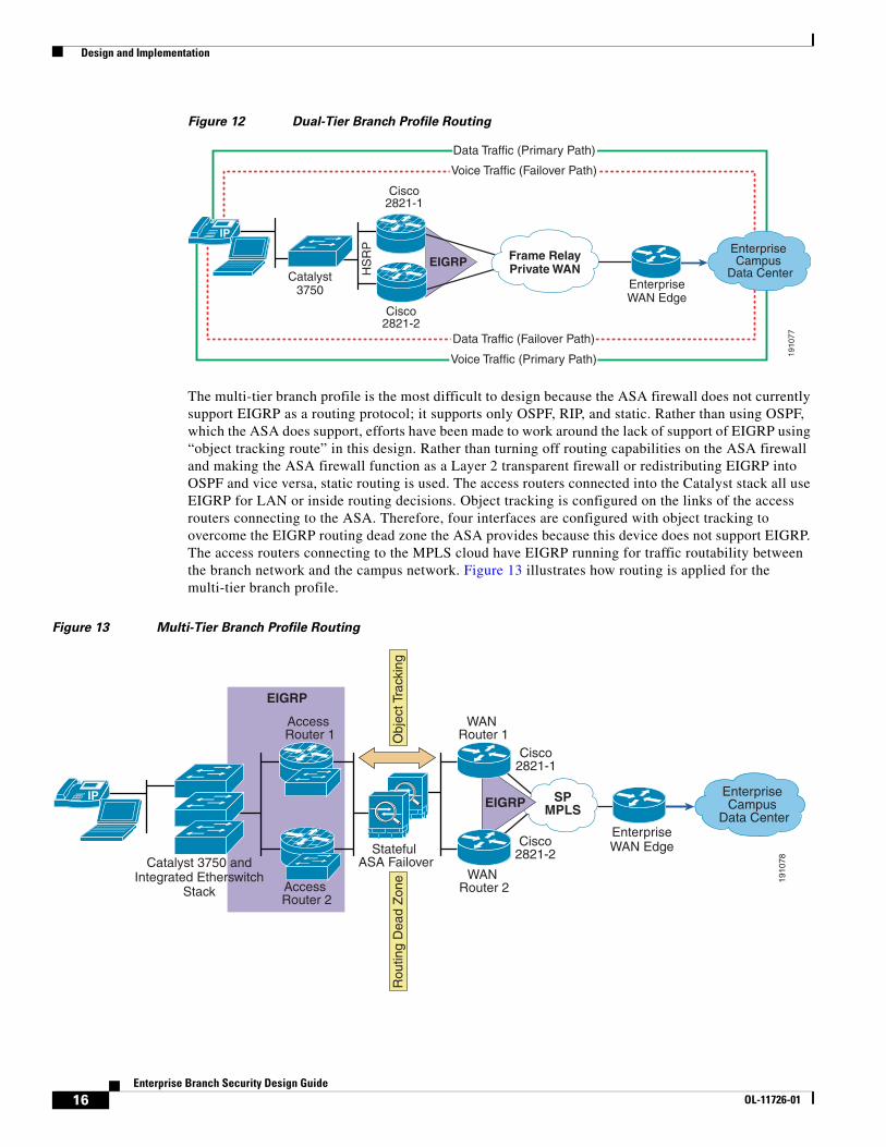
The multi-tier branch profile is the most difficult to design because the ASA firewall does not currently support EIGRP as a routing protocol; it supports only OSPF, RIP, and static. Rather than using OSPF, which the ASA does support, efforts have been made to work around the lack of support of EIGRP using “object tracking route” in this design. Rather than turning off routing capabilities on the ASA firewall and making the ASA firewall function as a Layer 2 transparent firewall or redistributing EIGRP into OSPF and vice versa, static routing is used. The access routers connected into the Catalyst stack all use EIGRP for LAN or inside routing decisions. Object tracking is configured on the links of the access routers connecting to the ASA. Therefore, four interfaces are configured with object tracking to overcome the EIGRP routing dead zone the ASA provides because this device does not support EIGRP. The access routers connecting to the MPLS cloud have EIGRP running for traffic routability between the branch network and the campus network. Figure 13 illustrates how routing is applied for the multi-tier branch profile.
Figure 13 Multi-Tier Branch Profile Routing
EIGRP
1910
77
Catalyst3750
IP
Frame RelayPrivate WAN
EnterpriseWAN Edge
Enterprise Campus
Data Center
Cisco2821-1
Cisco2821-2
HS
RP
Data Traffic (Failover Path)
Voice Traffic (Primary Path)
Data Traffic (Primary Path)
Voice Traffic (Failover Path)
1910
78Catalyst 3750 andIntegrated Etherswitch
Stack
EIGRP
Obj
ect T
rack
ing
Rou
ting
Dea
d Z
one
EIGRP
Cisco2821-1
Cisco2821-2
IP SPMPLS
EnterpriseWAN Edge
Enterprise Campus
Data Center
Access Router 1
Access Router 2
Stateful ASA Failover
WAN Router 1
WAN Router 2
16Enterprise Branch Security Design Guide
OL-11726-01
Design and Implementation
The Enhanced Object Tracking feature is used as a failover mechanism similar to how HSRP is used in the dual-tier branch profile. HSRP tracks interface line-protocol state only. If the line protocol of the interface goes down, the HSRP priority of the access router is reduced, allowing another HSRP router with a higher priority to become active. Object tracking can track the IP routing state of the interface, the line protocol state of the interface, IP route reachability, threshold weight, and threshold percentage. Boolean expressions are used to make failover routing decisions with very minimal reconvergence time.
For more information on all the IP routing protocols, see the following URL: http://www.cisco.com/en/US/products/ps6599/products_ios_protocol_group_home.html
As with all designs, the IP addressing and routing protocols chosen is entirely dependent on an individual customer network. Although this section is meant to show guidance for the three profiles tested, http://www.cisco.com provides much documentation for this topic as reference material as well.
Quality of Service
Each of the three profiles chosen serve as a transport for delay-sensitive voice, bandwidth-intensive video, and data applications. QoS is a Cisco IOS software feature that helps manage delay, delay variation (jitter), bandwidth, and packet loss on a network to guarantee efficient, predictable services for business-critical applications. There are various ways to enable QoS on a network. All three profiles use these methods in the same way, so there is no need to individually address each profile. QoS can be enabled on access routers and both the external Catalyst switches and the integrated EtherSwitch service module. The major categories of QoS tested in this design chapter are as follows:
• Classification and marking
• Congestion avoidance
• Congestion management
• Traffic conditioning
• Scavenger class QoS
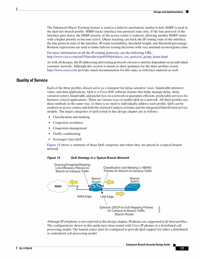
Figure 14 shows a summary of these QoS categories and where they are placed in a typical branch network.
Figure 14 QoS Strategy in a Typical Branch Network
Although IP telephony is not explored in this design chapter, IP phones are supported in all three profiles. The configurations shown in this guide have been tested with Cisco IP phones in a distributed call processing model. The branch router must be configured to provide QoS support for either a distributed or centralized call processing model.
1910
79
WAN
Queuing/Dropping/Shaping/Link-Efficiency Policies forBranch-to-Campus Traffic
Classification and Marking (+ NBAR) Policies for Branch-to-Campus Traffic
Optional: DSCP-to-CoS Mapping Policiesfor Campus-to-Branch Traffic
WAN Edge
Branch Router
BranchSwitch
LAN Edge
BranchRouter
17Enterprise Branch Security Design Guide
OL-11726-01
Design and Implementation
Packet classification allows traffic to be associated with a priority level or class of service. Packets are selected from a variety of methods ranging from simple the input interface, to access control lists (ACLs), to multi-packet classification using Network-Based Application Recognition (NBAR). NBAR classifies the IP traffic by application level protocol by monitoring the control flows of an application to be able to also correctly classify any new resulting flows. Classification is the first component of Modular QoS CLI (MQC) to allow for clear separation of classes, from the policy applied on the classes to the application of a QoS policy on an interface or subinterface on an access router or switch. Each profile uses NBAR and ACLs to classify traffic. Packets were marked using Layer 2-802.1p/Q, Layer 3- IP precedence, and Differentiated Services Code Point (DSCP) using the policy framework component of MQC.
Weighted random early detection (WRED) algorithm provides for congestion avoidance on network interfaces by providing buffer management and allowing TCP traffic to throttle back before buffers are exhausted. This helps avoid tail drops and global synchronization issues, thereby maximizing network utilization and TCP-based application performance.
Queuing techniques such as weighted fair queuing (WFQ), class-based weighted fair queuing (CBWFQ), low latency queuing (LLQ), and modified deficit round robin (MDRR) are necessary to ensure that critical applications get forwarded even during network congestion. Real-time applications such as voice or video that need to be forwarded with the least latency and jitter use LLQ. Non-delay sensitive traffic can use CBWFQ or MDRR.
Traffic entering a network can be conditioned by using a policer or a shaper. A policer enforces a rate limit while a shaper limits the traffic flow to a specified rate using buffers.
QoS can also provide network security by using scavenger class QoS. The scavenger class QoS strategy identifies known worms and attacks. In a branch network, the end user is a device located on the local LAN residing on a Catalyst switch LAN port. Other traffic patterns from that end user that are considered “unusual” or as “normal traffic but at an unusually high rate” may be marked as Scavenger Class-CS1 in the DSCP field and allowed to pass through the switch. Through the use of the scavenger class, QoS can be used as a security mechanism to limit the arrival rate of any traffic that is destined for the firewall or Intrusion Prevention System (IPS) configurations.
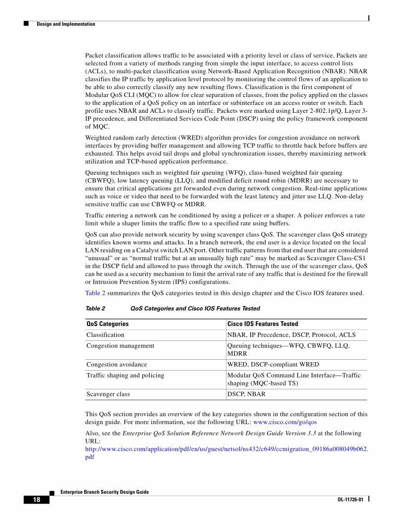
Table 2 summarizes the QoS categories tested in this design chapter and the Cisco IOS features used.
This QoS section provides an overview of the key categories shown in the configuration section of this design guide. For more information, see the following URL: www.cisco.com/go/qos
Also, see the Enterprise QoS Solution Reference Network Design Guide Version 3.3 at the following URL: http://www.cisco.com/application/pdf/en/us/guest/netsol/ns432/c649/ccmigration_09186a008049b062.pdf
Table 2 QoS Categories and Cisco IOS Features Tested
QoS Categories Cisco IOS Features Tested
Classification NBAR, IP Precedence, DSCP, Protocol, ACLS
Congestion management Queuing techniques—WFQ, CBWFQ, LLQ, MDRR
Congestion avoidance WRED, DSCP-compliant WRED
Traffic shaping and policing Modular QoS Command Line Interface—Traffic shaping (MQC-based TS)
Scavenger class DSCP, NBAR
18Enterprise Branch Security Design Guide
OL-11726-01
Design and Implementation
Security ServicesSecurity services help protect the device and network from intrusion, tampering manipulation (also called data integrity), secure data transport, and denial of service (DoS). The key categories of security services are the following:
• Infrastructure protection
• Secure connectivity
• Threat defense detection and mitigation
Infrastructure Protection
Infrastructure protection provides proactive measures to protect the infrastructure devices; in this case, Cisco IOS Software-based routers, switches, and appliances, from direct attacks as well as indirect attacks.
Infrastructure protection assists in maintaining network transport continuity and availability. Regardless of the profile chosen, the same methods for infrastructure protection apply. Rather than individually addressing each profile in detail, infrastructure protection applies to all the network components in the branch network. That is, the same infrastructure protection methods apply to access routers, switches, and security appliances. To protect these devices, the following methods are used:
• Turning off unnecessary services—Turning off unnecessary services means disabling any known potentially hazardous interface features and any global services not specifically required in the architecture. Under each interface in a device, IP redirects, IP unreachables, and IP proxy-ARP should be disabled. Global services such as service pad, service udp-small-servers, tcp small-servers, and IP bootp server should be disabled. For Catalyst switches, Cisco recommends to shut down any ports not in use and to disable auto-negotiated trunking on a port to make a port a non-trunking, non-tagged single VLAN Layer 2 interface.
• Enabling logging—Access control of SNMP or internally logging on the access router should be configured to ensure that there is a tracking mechanism when any unusual activity occurs.
• Enabling SSH—Enabling SSH and disabling Telnet for remote authentication provides an encryption shell and adds to the privacy of the network administrator control sessions to prevent snooping by unwanted parties and authentication.
• Enabling HTTPS—Similar to enabling only SSH for remote access, enabling only HTTPS for web connectivity provides an additional layer of protection for remote access.
• Enabling VTY, console and AUX timeouts, and ACLs—All VTY, console, and AUX ports should be set with timeouts to automatically drop any idle sessions. ACLs should be applied to restrict access to a device. Only allowed protocols should be permitted to the devices for administrative and monitoring purposes.
• Password management—Password management ensures that only approved users can access the device or services within a network. Local login can be configured on the router with password encryption as a basic way to monitor passwords. This method is quick and easy and suitable for a small number of users requiring authentication. For more robust authentication or for a larger user base, the recommendation is to use an authentication, authorization, and accounting (AAA) server for password management. Either a TACACS+ or RADIUS server is necessary for device account administration, command authorization, and CLI command accounting. For more information on AAA, TACACS+, or RADIUS, see the following URL: http://www.cisco.com/en/US/products/sw/iosswrel/ps1835/products_configuration_guide_chapter09186a00800ca7a7.html
19Enterprise Branch Security Design Guide
OL-11726-01
Design and Implementation
For more information on infrastructure protection techniques, see the following URL: http://www.cisco.com/application/pdf/en/us/guest/products/ps1838/c1244/cdccont_0900aecd804ac831.pdf
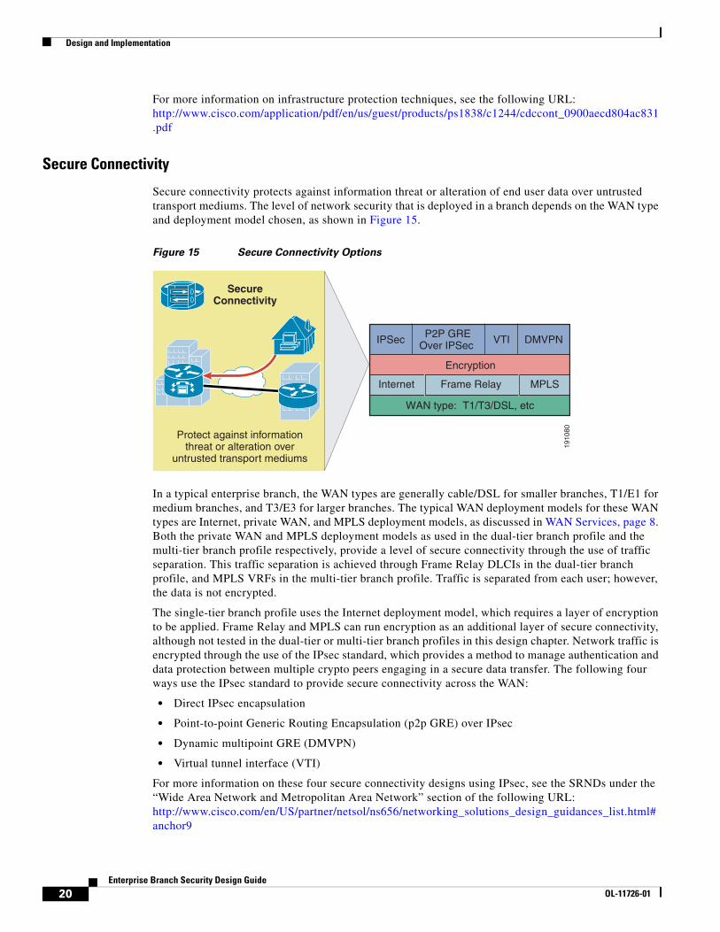
Secure Connectivity
Secure connectivity protects against information threat or alteration of end user data over untrusted transport mediums. The level of network security that is deployed in a branch depends on the WAN type and deployment model chosen, as shown in Figure 15.
Figure 15 Secure Connectivity Options
In a typical enterprise branch, the WAN types are generally cable/DSL for smaller branches, T1/E1 for medium branches, and T3/E3 for larger branches. The typical WAN deployment models for these WAN types are Internet, private WAN, and MPLS deployment models, as discussed in WAN Services, page 8. Both the private WAN and MPLS deployment models as used in the dual-tier branch profile and the multi-tier branch profile respectively, provide a level of secure connectivity through the use of traffic separation. This traffic separation is achieved through Frame Relay DLCIs in the dual-tier branch profile, and MPLS VRFs in the multi-tier branch profile. Traffic is separated from each user; however, the data is not encrypted.
The single-tier branch profile uses the Internet deployment model, which requires a layer of encryption to be applied. Frame Relay and MPLS can run encryption as an additional layer of secure connectivity, although not tested in the dual-tier or multi-tier branch profiles in this design chapter. Network traffic is encrypted through the use of the IPsec standard, which provides a method to manage authentication and data protection between multiple crypto peers engaging in a secure data transfer. The following four ways use the IPsec standard to provide secure connectivity across the WAN:
• Direct IPsec encapsulation
• Point-to-point Generic Routing Encapsulation (p2p GRE) over IPsec
• Dynamic multipoint GRE (DMVPN)
• Virtual tunnel interface (VTI)
For more information on these four secure connectivity designs using IPsec, see the SRNDs under the “Wide Area Network and Metropolitan Area Network” section of the following URL: http://www.cisco.com/en/US/partner/netsol/ns656/networking_solutions_design_guidances_list.html#anchor9
1910
80
SecureConnectivity
Protect against informationthreat or alteration over
untrusted transport mediums
WAN type: T1/T3/DSL, etc
MPLSFrame RelayInternet
Encryption
IPSec P2P GREOver IPSec VTI DMVPN
20Enterprise Branch Security Design Guide
OL-11726-01
Design and Implementation
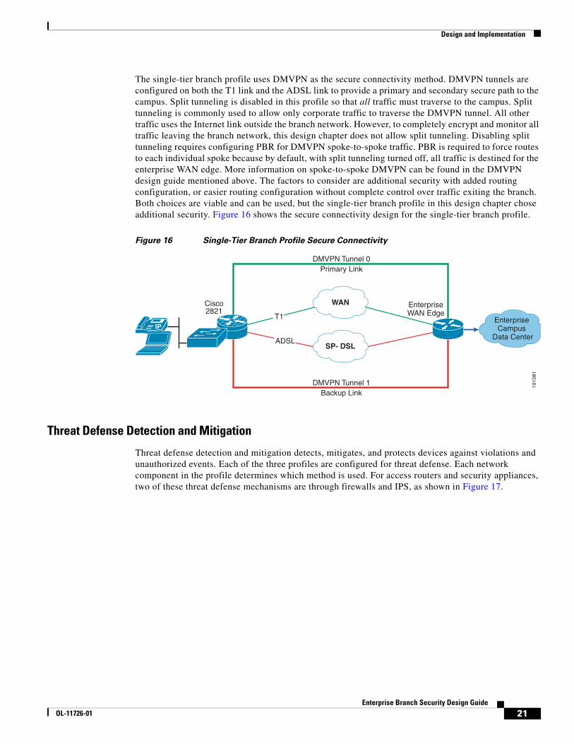
The single-tier branch profile uses DMVPN as the secure connectivity method. DMVPN tunnels are configured on both the T1 link and the ADSL link to provide a primary and secondary secure path to the campus. Split tunneling is disabled in this profile so that all traffic must traverse to the campus. Split tunneling is commonly used to allow only corporate traffic to traverse the DMVPN tunnel. All other traffic uses the Internet link outside the branch network. However, to completely encrypt and monitor all traffic leaving the branch network, this design chapter does not allow split tunneling. Disabling split tunneling requires configuring PBR for DMVPN spoke-to-spoke traffic. PBR is required to force routes to each individual spoke because by default, with split tunneling turned off, all traffic is destined for the enterprise WAN edge. More information on spoke-to-spoke DMVPN can be found in the DMVPN design guide mentioned above. The factors to consider are additional security with added routing configuration, or easier routing configuration without complete control over traffic exiting the branch. Both choices are viable and can be used, but the single-tier branch profile in this design chapter chose additional security. Figure 16 shows the secure connectivity design for the single-tier branch profile.
Figure 16 Single-Tier Branch Profile Secure Connectivity
Threat Defense Detection and Mitigation
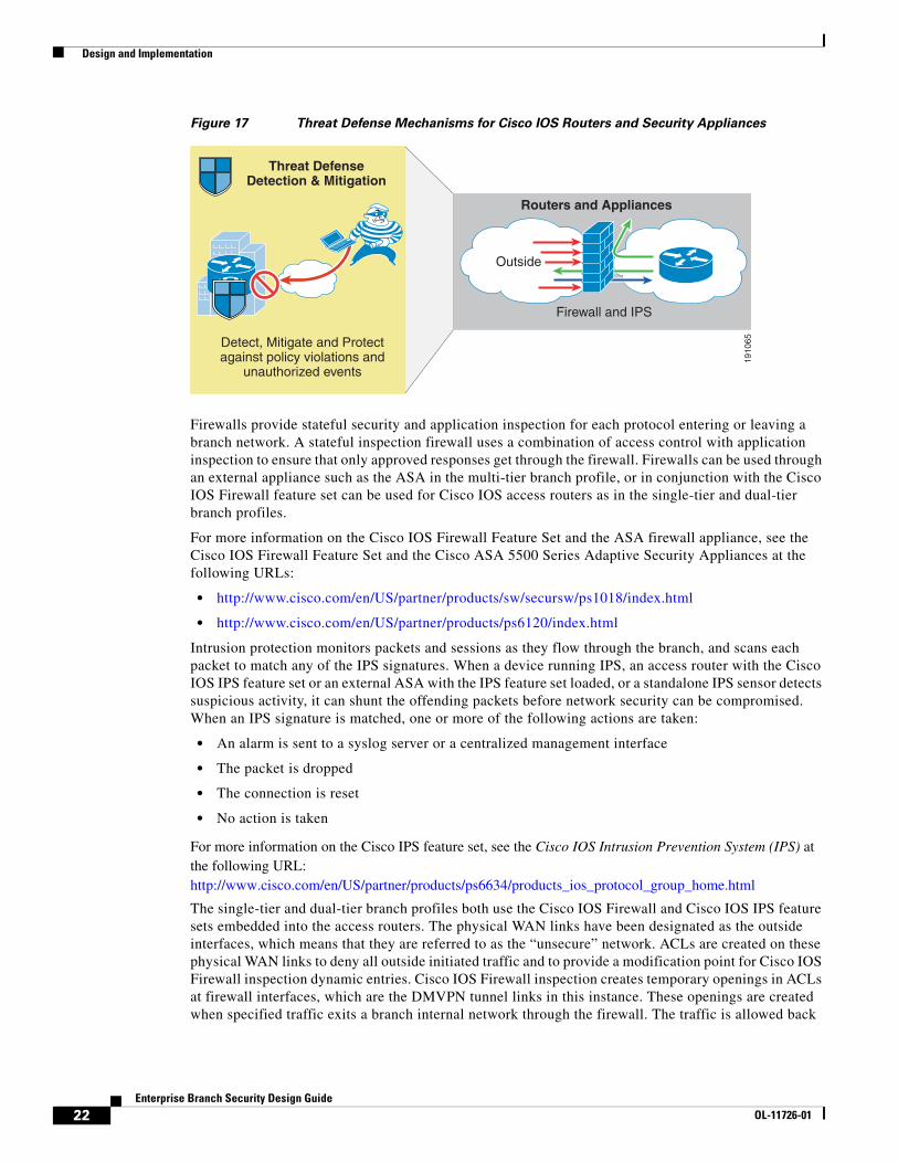
Threat defense detection and mitigation detects, mitigates, and protects devices against violations and unauthorized events. Each of the three profiles are configured for threat defense. Each network component in the profile determines which method is used. For access routers and security appliances, two of these threat defense mechanisms are through firewalls and IPS, as shown in Figure 17.
1910
81
IP
DMVPN Tunnel 0Primary Link
WAN
SP- DSL
DMVPN Tunnel 1Backup Link
EnterpriseWAN Edge
Enterprise Campus
Data Center
Cisco2821
T1
ADSL
21Enterprise Branch Security Design Guide
OL-11726-01
Design and Implementation
Figure 17 Threat Defense Mechanisms for Cisco IOS Routers and Security Appliances
Firewalls provide stateful security and application inspection for each protocol entering or leaving a branch network. A stateful inspection firewall uses a combination of access control with application inspection to ensure that only approved responses get through the firewall. Firewalls can be used through an external appliance such as the ASA in the multi-tier branch profile, or in conjunction with the Cisco IOS Firewall feature set can be used for Cisco IOS access routers as in the single-tier and dual-tier branch profiles.
For more information on the Cisco IOS Firewall Feature Set and the ASA firewall appliance, see the Cisco IOS Firewall Feature Set and the Cisco ASA 5500 Series Adaptive Security Appliances at the following URLs:
• http://www.cisco.com/en/US/partner/products/sw/secursw/ps1018/index.html
• http://www.cisco.com/en/US/partner/products/ps6120/index.html
Intrusion protection monitors packets and sessions as they flow through the branch, and scans each packet to match any of the IPS signatures. When a device running IPS, an access router with the Cisco IOS IPS feature set or an external ASA with the IPS feature set loaded, or a standalone IPS sensor detects suspicious activity, it can shunt the offending packets before network security can be compromised. When an IPS signature is matched, one or more of the following actions are taken:
• An alarm is sent to a syslog server or a centralized management interface
• The packet is dropped
• The connection is reset
• No action is taken
For more information on the Cisco IPS feature set, see the Cisco IOS Intrusion Prevention System (IPS) at the following URL: http://www.cisco.com/en/US/partner/products/ps6634/products_ios_protocol_group_home.html
The single-tier and dual-tier branch profiles both use the Cisco IOS Firewall and Cisco IOS IPS feature sets embedded into the access routers. The physical WAN links have been designated as the outside interfaces, which means that they are referred to as the “unsecure” network. ACLs are created on these physical WAN links to deny all outside initiated traffic and to provide a modification point for Cisco IOS Firewall inspection dynamic entries. Cisco IOS Firewall inspection creates temporary openings in ACLs at firewall interfaces, which are the DMVPN tunnel links in this instance. These openings are created when specified traffic exits a branch internal network through the firewall. The traffic is allowed back
Threat DefenseDetection & Mitigation
Detect, Mitigate and Protectagainst policy violations and
unauthorized events
1910
65
Firewall and IPS
Outside
Routers and Appliances
22Enterprise Branch Security Design Guide
OL-11726-01
Design and Implementation
through the firewall only if it is part of the same session of the internal network of the branch as the original traffic that was identified by the Cisco IOS Firewall. Cisco IOS Firewall inspection policies are configured on the DMVPN tunnel links as well.
Only ACLs are configured on the internal interfaces. These interfaces are the LAN interfaces from the access router and the integrated EtherSwitch module for the single-tier branch profile and the link between the external switch and the access router for the dual-tier branch profile. These ACLs only permit or deny specific user traffic. The benefit of these ACLs guarantees is that only allowed user networks can enter a branch network. Unwanted networks are denied.
The multi-tier branch profile is different in that the WAN links are terminated at the first set of access routers, and then this traffic is passed to the ASA for firewall functionality. ACLs can be configured on the WAN termination access routers to deny all outside initiated traffic as a threat defense mechanism. The ASA provides hardware-based, robust firewall capabilities compared to the Cisco IOS Firewall inspection functionality. The same principles apply, but the ASA is functioning only for firewall capabilities. The network behind the ASA is considered the inside secure network, and only ACLs are configured to permit or deny specific user traffic.
IPS is configured on all outside and inside interfaces for all three profiles. Traffic, regardless of whether it is a WAN link to the public or an internal LAN link, is inspected. In testing, IPS signatures 1107 (RFC 1918—Addresses Seen), 2000 (ICMP Echo Reply), and 2001 (ICMP Host Unreachable) are disabled. These signatures can trigger false positives in the lab environment. Running the default IPS signatures loaded with each Cisco IOS release should be sufficient, but updates to the signature file can be made as new signatures are added. A complete list of IPS signatures is located at the following URL: http://www.cisco.com/en/US/partner/products/ps6634/products_white_paper0900aecd8039e2e4.shtml
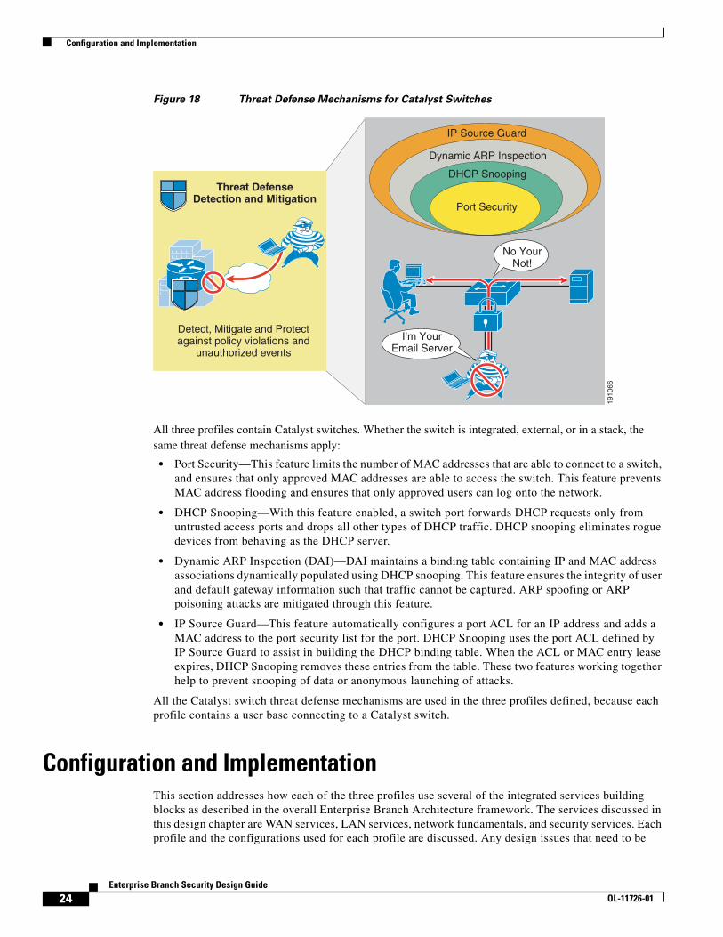
Cisco Catalyst switches have additional mechanisms for threat defense that are applied on a per-port basis, that include the following:
• Port Security
• DHCP Snooping
• Dynamic ARP Inspection
• IP Source Guard
Figure 18 shows these mechanisms.
23Enterprise Branch Security Design Guide
OL-11726-01
Configuration and Implementation
Figure 18 Threat Defense Mechanisms for Catalyst Switches
All three profiles contain Catalyst switches. Whether the switch is integrated, external, or in a stack, the same threat defense mechanisms apply:
• Port Security—This feature limits the number of MAC addresses that are able to connect to a switch, and ensures that only approved MAC addresses are able to access the switch. This feature prevents MAC address flooding and ensures that only approved users can log onto the network.
• DHCP Snooping—With this feature enabled, a switch port forwards DHCP requests only from untrusted access ports and drops all other types of DHCP traffic. DHCP snooping eliminates rogue devices from behaving as the DHCP server.
• Dynamic ARP Inspection (DAI)—DAI maintains a binding table containing IP and MAC address associations dynamically populated using DHCP snooping. This feature ensures the integrity of user and default gateway information such that traffic cannot be captured. ARP spoofing or ARP poisoning attacks are mitigated through this feature.
• IP Source Guard—This feature automatically configures a port ACL for an IP address and adds a MAC address to the port security list for the port. DHCP Snooping uses the port ACL defined by IP Source Guard to assist in building the DHCP binding table. When the ACL or MAC entry lease expires, DHCP Snooping removes these entries from the table. These two features working together help to prevent snooping of data or anonymous launching of attacks.
All the Catalyst switch threat defense mechanisms are used in the three profiles defined, because each profile contains a user base connecting to a Catalyst switch.
Configuration and ImplementationThis section addresses how each of the three profiles use several of the integrated services building blocks as described in the overall Enterprise Branch Architecture framework. The services discussed in this design chapter are WAN services, LAN services, network fundamentals, and security services. Each profile and the configurations used for each profile are discussed. Any design issues that need to be
1910
66
Threat DefenseDetection and Mitigation
Detect, Mitigate and Protectagainst policy violations and
unauthorized events
IP Source Guard
Dynamic ARP Inspection
DHCP Snooping
Port Security
No YourNot!
I’m YourEmail Server
24Enterprise Branch Security Design Guide
OL-11726-01
Configuration and Implementation
considered for each service or each profile are addressed as well. The following figures illustrate the network topology used for each profile. These figures should be referenced as each integrated service is described in more detail.
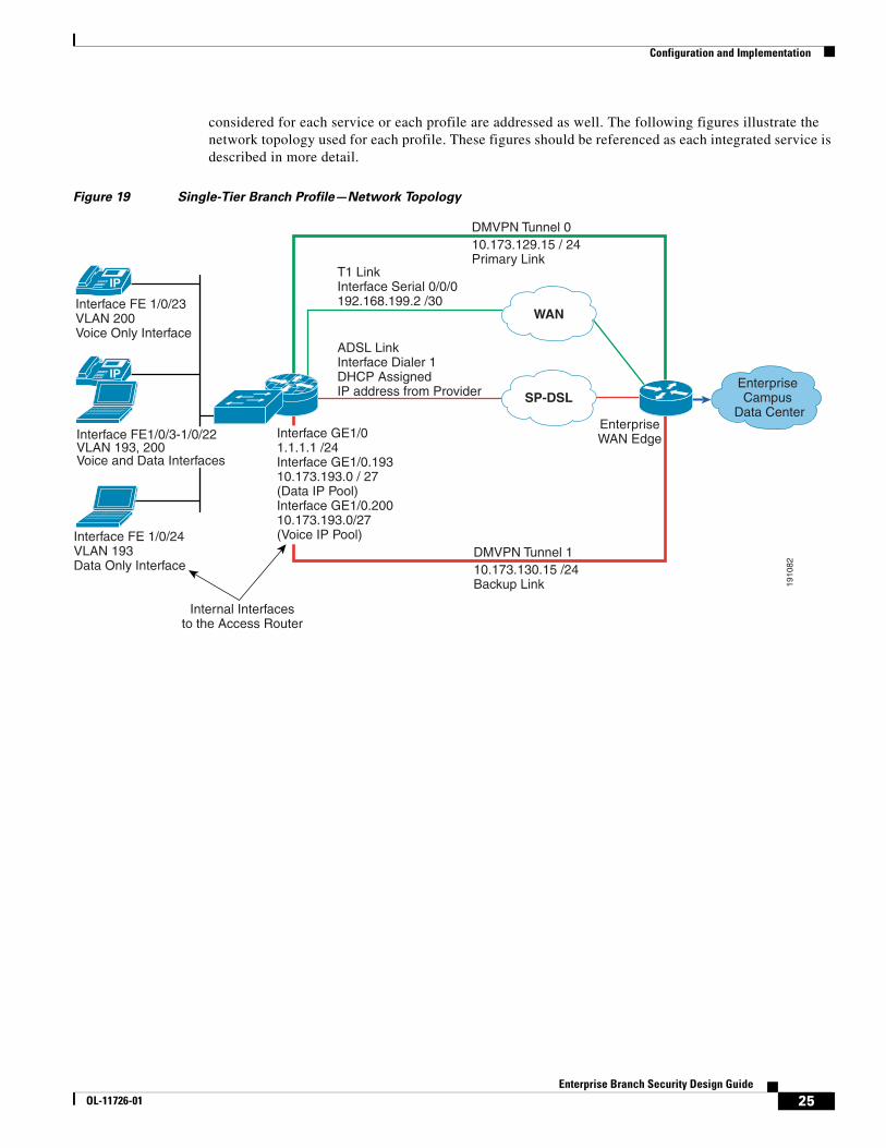
Figure 19 Single-Tier Branch Profile—Network Topology
1910
82
Interface FE 1/0/23VLAN 200Voice Only Interface
Interface FE 1/0/24VLAN 193Data Only Interface
Interface FE1/0/3-1/0/22VLAN 193, 200Voice and Data Interfaces
IP
WAN
SP-DSL
EnterpriseWAN Edge
Enterprise Campus
Data Center
IP
Internal Interfacesto the Access Router
Interface GE1/01.1.1.1 /24Interface GE1/0.19310.173.193.0 / 27(Data IP Pool)Interface GE1/0.20010.173.193.0/27(Voice IP Pool)
T1 LinkInterface Serial 0/0/0192.168.199.2 /30
ADSL LinkInterface Dialer 1DHCP Assigned IP address from Provider
DMVPN Tunnel 110.173.130.15 /24Backup Link
DMVPN Tunnel 010.173.129.15 / 24Primary Link
25Enterprise Branch Security Design Guide
OL-11726-01
Configuration and Implementation
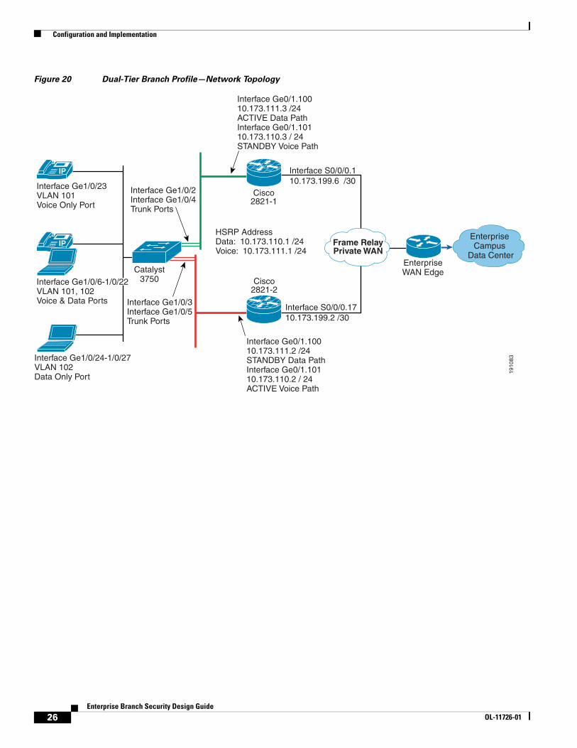
Figure 20 Dual-Tier Branch Profile—Network Topology
1910
83
IP Frame RelayPrivate WAN
EnterpriseWAN Edge
Enterprise Campus
Data Center
IP
Catalyst3750
Cisco2821-1
Cisco2821-2
Interface Ge1/0/23VLAN 101Voice Only Port
Interface Ge1/0/24-1/0/27VLAN 102Data Only Port
Interface Ge1/0/3 Interface Ge1/0/5Trunk Ports
Interface Ge1/0/2 Interface Ge1/0/4Trunk Ports
Interface Ge0/1.10010.173.111.3 /24 ACTIVE Data PathInterface Ge0/1.10110.173.110.3 / 24STANDBY Voice Path
Interface Ge0/1.10010.173.111.2 /24 STANDBY Data PathInterface Ge0/1.10110.173.110.2 / 24ACTIVE Voice Path
HSRP AddressData: 10.173.110.1 /24Voice: 10.173.111.1 /24
Interface S0/0/0.110.173.199.6 /30
Interface S0/0/0.1710.173.199.2 /30
Interface Ge1/0/6-1/0/22VLAN 101, 102Voice & Data Ports
26Enterprise Branch Security Design Guide
OL-11726-01
Configuration and Implementation
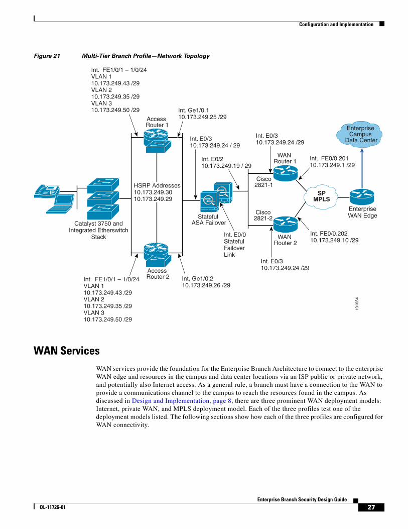
Figure 21 Multi-Tier Branch Profile—Network Topology
WAN ServicesWAN services provide the foundation for the Enterprise Branch Architecture to connect to the enterprise WAN edge and resources in the campus and data center locations via an ISP public or private network, and potentially also Internet access. As a general rule, a branch must have a connection to the WAN to provide a communications channel to the campus to reach the resources found in the campus. As discussed in Design and Implementation, page 8, there are three prominent WAN deployment models: Internet, private WAN, and MPLS deployment model. Each of the three profiles test one of the deployment models listed. The following sections show how each of the three profiles are configured for WAN connectivity.
1910
84
Catalyst 3750 andIntegrated Etherswitch
Stack
Int. FE1/0/1 – 1/0/24VLAN 110.173.249.43 /29VLAN 210.173.249.35 /29VLAN 310.173.249.50 /29
Int. FE1/0/1 – 1/0/24VLAN 110.173.249.43 /29VLAN 210.173.249.35 /29VLAN 310.173.249.50 /29
Int. Ge1/0.110.173.249.25 /29
Int, Ge1/0.210.173.249.26 /29
Int. E0/310.173.249.24 / 29
Int. E0/310.173.249.24 /29
Int. E0/310.173.249.24 /29
Int. FE0/0.20110.173.249.1 /29
Int. FE0/0.20210.173.249.10 /29
HSRP Addresses10.173.249.3010.173.249.29
Int. E0/0StatefulFailoverLink
Int. E0/210.173.249.19 / 29
IP SPMPLS
EnterpriseWAN Edge
Enterprise Campus
Data Center
Access Router 1
Access Router 2
WAN Router 1
WAN Router 2
Cisco2821-1
Cisco2821-2Stateful
ASA Failover
27Enterprise Branch Security Design Guide
OL-11726-01
Configuration and Implementation
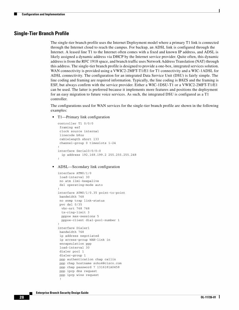
Single-Tier Branch Profile
The single-tier branch profile uses the Internet Deployment model where a primary T1 link is connected through the Internet cloud to reach the campus. For backup, an ADSL link is configured through the Internet. A leased line T1 to the Internet often comes with a fixed and known IP address, and ADSL is likely assigned a dynamic address via DHCP by the Internet service provider. Quite often, this dynamic address is from the RFC 1918 space, and branch traffic uses Network Address Translation (NAT) through this address. The single-tier branch profile is designed to provide a one-box, integrated services solution. WAN connectivity is provided using a VWIC2-2MFT-T1/E1 for T1 connectivity and a WIC-1ADSL for ADSL connectivity. The configuration for an integrated Data Service Unit (DSU) is fairly simple. The line coding and framing are required information. Typically, the line coding is B8ZS and the framing is ESF, but always confirm with the service provider. Either a WIC-1DSU-T1 or a VWIC2-2MFT-T1/E1 can be used. The latter is preferred because it implements more features and positions the deployment for an easy migration to future voice services. As such, the integrated DSU is configured as a T1 controller.
The configurations used for WAN services for the single-tier branch profile are shown in the following examples:
• T1—Primary link configuration
controller T1 0/0/0 framing esf clock source internal linecode b8zs cablelength short 133 channel-group 0 timeslots 1-24!interface Serial0/0/0:0 ip address 192.168.199.2 255.255.255.248!
• ADSL—Secondary link configuration
interface ATM0/1/0 load-interval 30 no atm ilmi-keepalive dsl operating-mode auto!interface ATM0/1/0.35 point-to-point bandwidth 768 no snmp trap link-status pvc dsl 0/35 vbr-nrt 768 768 tx-ring-limit 3 pppoe max-sessions 5 pppoe-client dial-pool-number 1!interface Dialer1 bandwidth 768 ip address negotiated ip access-group WAN-link in encapsulation ppp load-interval 30 dialer pool 1 dialer-group 1 ppp authentication chap callin ppp chap hostname [email protected] ppp chap password 7 1316181A0458 ppp ipcp dns request ppp ipcp wins request !
28Enterprise Branch Security Design Guide
OL-11726-01
Configuration and Implementation
dialer-list 1 protocol ip permit
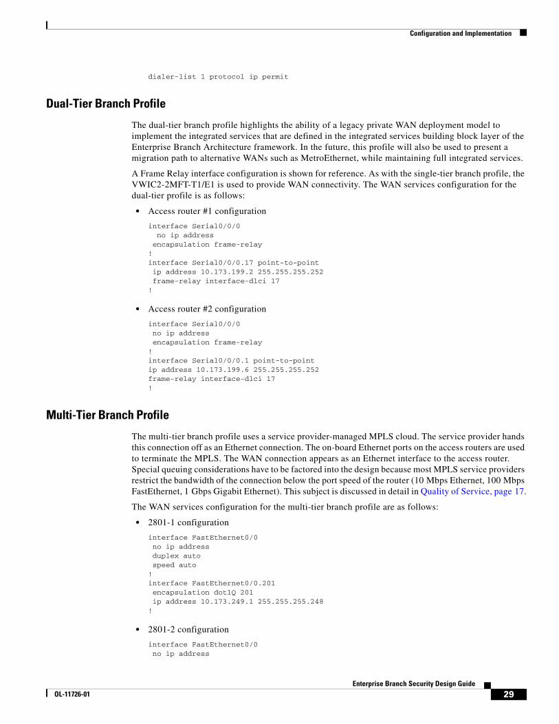
Dual-Tier Branch Profile
The dual-tier branch profile highlights the ability of a legacy private WAN deployment model to implement the integrated services that are defined in the integrated services building block layer of the Enterprise Branch Architecture framework. In the future, this profile will also be used to present a migration path to alternative WANs such as MetroEthernet, while maintaining full integrated services.
A Frame Relay interface configuration is shown for reference. As with the single-tier branch profile, the VWIC2-2MFT-T1/E1 is used to provide WAN connectivity. The WAN services configuration for the dual-tier profile is as follows:
• Access router #1 configuration
interface Serial0/0/0 no ip address encapsulation frame-relay!interface Serial0/0/0.17 point-to-point ip address 10.173.199.2 255.255.255.252 frame-relay interface-dlci 17!
• Access router #2 configuration
interface Serial0/0/0 no ip address encapsulation frame-relay!interface Serial0/0/0.1 point-to-point ip address 10.173.199.6 255.255.255.252frame-relay interface-dlci 17!
Multi-Tier Branch Profile
The multi-tier branch profile uses a service provider-managed MPLS cloud. The service provider hands this connection off as an Ethernet connection. The on-board Ethernet ports on the access routers are used to terminate the MPLS. The WAN connection appears as an Ethernet interface to the access router. Special queuing considerations have to be factored into the design because most MPLS service providers restrict the bandwidth of the connection below the port speed of the router (10 Mbps Ethernet, 100 Mbps FastEthernet, 1 Gbps Gigabit Ethernet). This subject is discussed in detail in Quality of Service, page 17.
The WAN services configuration for the multi-tier branch profile are as follows:
• 2801-1 configuration
interface FastEthernet0/0 no ip address duplex auto speed auto!interface FastEthernet0/0.201 encapsulation dot1Q 201 ip address 10.173.249.1 255.255.255.248!
• 2801-2 configuration
interface FastEthernet0/0 no ip address
29Enterprise Branch Security Design Guide
OL-11726-01
Configuration and Implementation
duplex auto speed auto!interface FastEthernet0/0.202 encapsulation dot1Q 202 ip address 10.173.249.10 255.255.255.248!
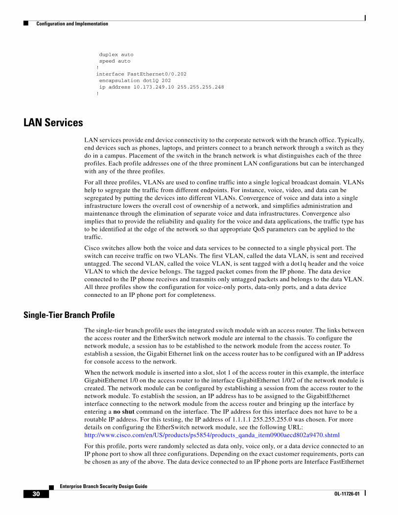
LAN ServicesLAN services provide end device connectivity to the corporate network with the branch office. Typically, end devices such as phones, laptops, and printers connect to a branch network through a switch as they do in a campus. Placement of the switch in the branch network is what distinguishes each of the three profiles. Each profile addresses one of the three prominent LAN configurations but can be interchanged with any of the three profiles.
For all three profiles, VLANs are used to confine traffic into a single logical broadcast domain. VLANs help to segregate the traffic from different endpoints. For instance, voice, video, and data can be segregated by putting the devices into different VLANs. Convergence of voice and data into a single infrastructure lowers the overall cost of ownership of a network, and simplifies administration and maintenance through the elimination of separate voice and data infrastructures. Convergence also implies that to provide the reliability and quality for the voice and data applications, the traffic type has to be identified at the edge of the network so that appropriate QoS parameters can be applied to the traffic.
Cisco switches allow both the voice and data services to be connected to a single physical port. The switch can receive traffic on two VLANs. The first VLAN, called the data VLAN, is sent and received untagged. The second VLAN, called the voice VLAN, is sent tagged with a dot1q header and the voice VLAN to which the device belongs. The tagged packet comes from the IP phone. The data device connected to the IP phone receives and transmits only untagged packets and belongs to the data VLAN. All three profiles show the configuration for voice-only ports, data-only ports, and a data device connected to an IP phone port for completeness.
Single-Tier Branch Profile
The single-tier branch profile uses the integrated switch module with an access router. The links between the access router and the EtherSwitch network module are internal to the chassis. To configure the network module, a session has to be established to the network module from the access router. To establish a session, the Gigabit Ethernet link on the access router has to be configured with an IP address for console access to the network.
When the network module is inserted into a slot, slot 1 of the access router in this example, the interface GigabitEthernet 1/0 on the access router to the interface GigabitEthernet 1/0/2 of the network module is created. The network module can be configured by establishing a session from the access router to the network module. To establish the session, an IP address has to be assigned to the GigabitEthernet interface connecting to the network module from the access router and bringing up the interface by entering a no shut command on the interface. The IP address for this interface does not have to be a routable IP address. For this testing, the IP address of 1.1.1.1 255.255.255.0 was chosen. For more details on configuring the EtherSwitch network module, see the following URL: http://www.cisco.com/en/US/products/ps5854/products_qanda_item0900aecd802a9470.shtml
For this profile, ports were randomly selected as data only, voice only, or a data device connected to an IP phone port to show all three configurations. Depending on the exact customer requirements, ports can be chosen as any of the above. The data device connected to an IP phone ports are Interface FastEthernet
30Enterprise Branch Security Design Guide
OL-11726-01
Configuration and Implementation
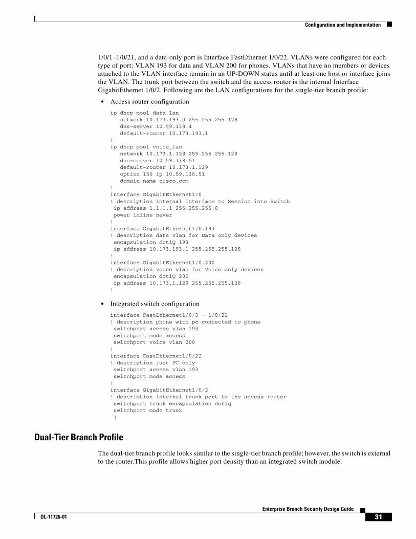
1/0/1–1/0/21, and a data-only port is Interface FastEthernet 1/0/22. VLANs were configured for each type of port: VLAN 193 for data and VLAN 200 for phones. VLANs that have no members or devices attached to the VLAN interface remain in an UP-DOWN status until at least one host or interface joins the VLAN. The trunk port between the switch and the access router is the internal Interface GigabitEthernet 1/0/2. Following are the LAN configurations for the single-tier branch profile:
• Access router configuration
ip dhcp pool data_lan network 10.173.193.0 255.255.255.128 dns-server 10.59.138.4 default-router 10.173.193.1!ip dhcp pool voice_lan network 10.173.1.128 255.255.255.128 dns-server 10.59.138.51 default-router 10.173.1.129 option 150 ip 10.59.138.51 domain-name cisco.com!interface GigabitEthernet1/0! description Internal Interface to Session into Switch ip address 1.1.1.1 255.255.255.0 power inline never!interface GigabitEthernet1/0.193! description data vlan for Data only devices encapsulation dot1Q 193 ip address 10.173.193.1 255.255.255.128!interface GigabitEthernet1/0.200! description voice vlan for Voice only devices encapsulation dot1Q 200 ip address 10.173.1.129 255.255.255.128!
• Integrated switch configuration
interface FastEthernet1/0/3 – 1/0/21! description phone with pc connected to phone switchport access vlan 193 switchport mode access switchport voice vlan 200!interface FastEthernet1/0/22! description just PC only switchport access vlan 193 switchport mode access!interface GigabitEthernet1/0/2! description internal trunk port to the access router switchport trunk encapsulation dot1q switchport mode trunk !
Dual-Tier Branch Profile
The dual-tier branch profile looks similar to the single-tier branch profile; however, the switch is external to the router.This profile allows higher port density than an integrated switch module.
31Enterprise Branch Security Design Guide
OL-11726-01
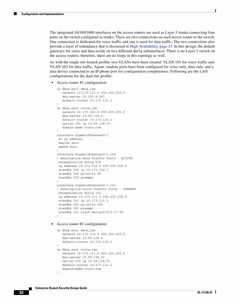
Configuration and Implementation
The integrated 10/100/1000 interfaces on the access routers are used as Layer 3 trunks connecting four ports on the switch configured as trunks. There are two connections on each access router to the switch. One connection is dedicated for voice traffic and one is used for data traffic. The two connections also provide a layer of redundancy that is discussed in High Availability, page 13. In this design, the default gateways for voice and data reside on two different dot1q subinterfaces. There is no Layer 2 switch on the access routers; therefore, there are no loops in this topology as well.
As with the single-tier branch profile, two VLANs have been created: VLAN 101 for voice traffic and VLAN 102 for data traffic. Again, random ports have been configured for voice only, data only, and a data device connected to an IP phone port for configuration completeness. Following are the LAN configurations for the dual-tier profile:
• Access router #1 configuration
ip dhcp pool data_lan network 10.173.111.0 255.255.255.0 dns-server 10.102.6.247 default-router 10.173.111.1!ip dhcp pool voice_lan network 10.173.110.0 255.255.255.0 dns-server 10.59.138.4 default-router 10.173.110.1 option 150 ip 10.59.138.51 domain-name cisco.com!interface GigabitEthernet0/1 no ip address duplex auto speed auto!interface GigabitEthernet0/1.100! description Data Traffic Ports - ACTIVE encapsulation dot1Q 102 ip address 10.173.110.3 255.255.255.0 standby 100 ip 10.173.110.1 standby 100 priority 90 standby 100 preempt!interface GigabitEthernet0/1.101! description Voice Traffic Ports - STANDBY encapsulation dot1Q 101 ip address 10.173.111.3 255.255.255.0 standby 101 ip 10.173.111.1 standby 101 priority 120 standby 101 preempt standby 101 track Serial0/0/0.17 50!
• Access router #2 configuration
ip dhcp pool data_lan network 10.173.110.0 255.255.255.0 dns-server 10.59.138.4 default-router 10.173.110.1!ip dhcp pool voice_lan network 10.173.111.0 255.255.255.0 dns-server 10.59.138.51 option 150 ip 10.59.138.51 default-router 10.173.111.1 domain-name cisco.com!
32Enterprise Branch Security Design Guide
OL-11726-01
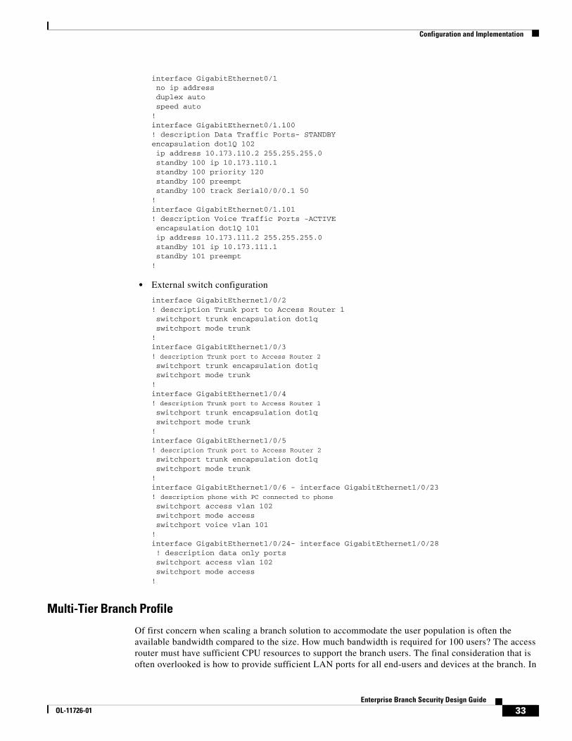
Configuration and Implementation
interface GigabitEthernet0/1 no ip address duplex auto speed auto!interface GigabitEthernet0/1.100! description Data Traffic Ports- STANDBYencapsulation dot1Q 102 ip address 10.173.110.2 255.255.255.0 standby 100 ip 10.173.110.1 standby 100 priority 120 standby 100 preempt standby 100 track Serial0/0/0.1 50!interface GigabitEthernet0/1.101! description Voice Traffic Ports -ACTIVE encapsulation dot1Q 101 ip address 10.173.111.2 255.255.255.0 standby 101 ip 10.173.111.1 standby 101 preempt!
• External switch configuration
interface GigabitEthernet1/0/2! description Trunk port to Access Router 1 switchport trunk encapsulation dot1q switchport mode trunk!interface GigabitEthernet1/0/3! description Trunk port to Access Router 2 switchport trunk encapsulation dot1q switchport mode trunk!interface GigabitEthernet1/0/4! description Trunk port to Access Router 1 switchport trunk encapsulation dot1q switchport mode trunk!interface GigabitEthernet1/0/5! description Trunk port to Access Router 2 switchport trunk encapsulation dot1q switchport mode trunk!interface GigabitEthernet1/0/6 - interface GigabitEthernet1/0/23! description phone with PC connected to phone switchport access vlan 102 switchport mode access switchport voice vlan 101!interface GigabitEthernet1/0/24- interface GigabitEthernet1/0/28 ! description data only ports switchport access vlan 102 switchport mode access!
Multi-Tier Branch Profile
Of first concern when scaling a branch solution to accommodate the user population is often the available bandwidth compared to the size. How much bandwidth is required for 100 users? The access router must have sufficient CPU resources to support the branch users. The final consideration that is often overlooked is how to provide sufficient LAN ports for all end-users and devices at the branch. In
33Enterprise Branch Security Design Guide
OL-11726-01
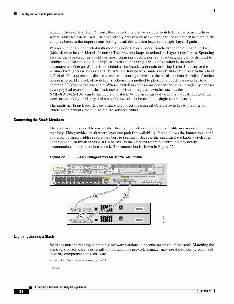
Configuration and Implementation
branch offices of less than 46 users, the connectivity can be a single switch. In larger branch offices, several switches can be used. The connectivity between these switches and the router can become fairly complex because the requirements for high availability often leads to multiple Layer 2 paths.
When switches are connected with more than one Layer 2 connection between them, Spanning Tree (802.1d) must be considered. Spanning Tree prevents loops in redundant Layer 2 topologies. Spanning Tree neither converges as quickly as most routing protocols, nor is it as robust, and can be difficult to troubleshoot. Minimizing the complexities of the Spanning Tree configuration is therefore advantageous. One possibility is to minimize the broadcast domain enabling Layer 3 routing to the wiring closet (access-layer) switch. VLANs are limited to a single switch and extend only to the client NIC card. This approach is discussed as part of routing service for the multi-tier branch profile. Another option is to build a stack of switches. Stackwise is a method to physically attach the switches to a common 32 Gbps backplane cable. When a switch becomes a member of the stack, it logically appears as an physical extension of the stack master switch. Integrated switches such as the NME-XD-24ES-1S-P can be members of a stack. When an integrated switch is used, it should be the stack master. Only one integrated stackable switch can be used in a single router chassis.
The multi-tier branch profile uses a stack to connect the external Catalyst switches to the internal EtherSwitch network module within the services router.
Connecting the Stack Members
The switches are connect to one another through a Stackwise interconnect cable in a round robin ring topology. This provides an alternate layer one path for availability. It also allows the branch to expand and grow by simply adding more members to the stack. Because the integrated stackable switch is a “double-wide” network module, a Cisco 2851 is the smallest router platform that physically accommodates integration into a stack. The connection is shown in Figure 22.
Figure 22 LAN Configuration for Multi-Tier Profile
Logically Joining a Stack
Switches must be running compatible software versions to become members of the stack. Matching the stack version software is especially important. The network manager may use the following command to verify compatible stack software
show platform stack-manager all
<snip>
1219
15A= ACT
FE 0/1
PVDM2 PVDM1 PVDM0 AIM1 AIM0
FE 0/0S= SPEED
A= FDXA= LINK
A
F
S
L
A
F
S
L
24x
SYST
MASTR
STAT
DU
PLX
SPEED
STACK
LINE PW
R
MO
DE
EN
LASERPRODUKT DER KLASSE 1
1PRODUCTO LASER CLASE 1 PRODUIT LASER DE CLASSE 1
CLASS 1 LASER PRODUCTARE ON THE FACEPLATE,
BE SECURED ALL 6-32 THUMB SCREWS MUST
WHILE HULC STACK CABLES
GE 1
2x
2x 1x4x 3x6x 5x8x 7x11x 9x12x14x 13x16x 15x18x 17x20x 19x22x 21x24x 23x 10x
A
C
B
NME-XD-24ES-1S-P
34Enterprise Branch Security Design Guide
OL-11726-01
Configuration and Implementation
Stack State Machine View==============================================================
Switch Master/ Mac Address Version Uptime CurrentNumber Slave (maj.min) State---------------------------------------------------------------------1 Master 0015.63d5.1a80 1.11 1442 Ready5 Slave 0013.8089.5800 1.11 1442 Ready
Determining the Stack Master
When a new stack is created, or when the current master fails, a new stack master must be elected. The following set of rules is used to determine how the master should be elected:
• The switch with the highest priority
• The switch with an existing interface configuration
• The switch with the most the most feature capability
• The switch with the longest uptime
• The switch with the lowest MAC address
As a best practice, network managers should manually configure the priority of the switch they want to be the stack. The features and capabilities of the master switch determine the capabilities of all members of the stack. Because of this behavior, all switches in the stack must have the same capabilities. Otherwise, if an existing master goes offline and another switch is selected as the new master, features are disabled and the configuration of the stack is changed.
Stack Fundamentals
Each stack member is assigned a number. New members are dynamically allocated with the lowest available number, and following command is placed in the configuration:
switch 1 provision ws-c3750g-24psswitch 5 provision nme-xd-24es-2st
The ports associated with this switch are numbered with either a 1/x/y or a 5/x/y, as for example:
GigabitEthernet1/0/1 unassigned YES unset up upGigabitEthernet1/0/2 unassigned YES unset down downGigabitEthernet1/0/3 unassigned YES unset down downGigabitEthernet1/0/4 unassigned YES unset down downGigabitEthernet1/0/5 unassigned YES unset down down..GigabitEthernet1/0/27 unassigned YES unset down downGigabitEthernet1/0/28 unassigned YES unset down downFastEthernet5/0/1 unassigned YES unset down downFastEthernet5/0/2 unassigned YES unset down downFastEthernet5/0/3 unassigned YES unset down down
It is possible to change the automatically-set switch number. However, it is not recommended because this impacts the configuration of the associated ports. Another situation that can damage the configuration is two independent stacks, each with a master that are merged together. Because the switch numbers must be unique, switches are renumbered to the lowest available value if there is a conflict with their current setting. Care should be exercised when either of these scenarios is possible.
35Enterprise Branch Security Design Guide
OL-11726-01
Configuration and Implementation
When a member switch fails, the associated ports on the stack are placed in the down state. The switch can be replaced with a similar switch that matches the provisioned switch. In this case, the ports recover without any need to manually update the new member with the configuration.
The following commands are useful when working with stacks:
• show switch
• show ver
• show platform stack-manager
• dir flashn: where n is the switch number
• remote command n <command> where n is the switch number
Implementing a Stack in the Profiles
Because the switches in the stack are logically a single device, they are well suited to fit into any of the profiles considered in this design architecture. This is especially true where a stackable integrated switch is used. The integrated switch of the router is configured to be the master by increasing the priority. Because this switch provides the sole connection to the branch router, the other switches in the stack are inherently subordinate to it. Allowing any other switch to be elected master can potentially interrupt connectivity to the main campus as stack members are added or removed, and the master election process must be invoked.
Network Fundamental ServicesLayer 3 path selection is fundamental in a design that requires high availability. If a branch cannot tolerate loss of connectivity to the campus, a redundant path is needed. Network topologies that contain redundant paths generally use a Layer 3 routing protocol to inject and withdraw two or more equal classes of service (CoS), or simply the preferred path, into the IP routing table.
Single-Tier Branch
Although this is the simplest branch profile in terms of the amount of devices, the routing design can actually become quite complex. This is often the case when many design requirements are placed on a single device as opposed to distributed across dedicated devices. In the single-tier branch profile, a public WAN such as the Internet is used. DMVPN can then be configured to provide a secure connection to both a primary and secondary head-end router in the enterprise WAN edge. This approach is discussed in the DMVPN design guide. Although this design guide covers the situation where the Internet connection from the primary head end or head ends fails, it does not cover the case where the Internet connection from the branch fails. The single-tier branch profile uses a second ADSL connection to the Internet to cover this situation.
At first glance, it would seem that the DMVPN tunnel could use either the primary connection or the ADSL connection to provide an Internet path to the campus, and that NHRP would manage the binding between the public address and tunnel address. However, this is very difficult in practice. Two factors limit this approach. First, the primary connection and the ADSL connection are always in a connected state. Second, the tunnel source address must be from a single physical interface. The tunnel source can not dynamically change between the two possible paths. This limitation requires that the tunnel be sourced from a loopback address that is routable on the public Internet. However, the enterprise WAN aggregation router needs to know when this loopback is reachable via the primary connection and when
36Enterprise Branch Security Design Guide
OL-11726-01

Configuration and Implementation
the ADSL connection must be used. This requires the branch router to support BGP peering with the Internet, which is not practical; or it requires the enterprise WAN edge to do object tracking over each connection towards the branch, which is not scalable.
A better approach is to configure a second DMVPN tunnel source from the ADSL interface of the branch and then use routing through the tunnel to provide path selection, as follows:
• Primary link
crypto isakmp policy 1 encr 3des authentication pre-sharecrypto isakmp key secret address 0.0.0.0 0.0.0.0crypto isakmp keepalive 10!crypto ipsec transform-set BRP esp-3des esp-sha-hmac!crypto ipsec profile DMVPN set transform-set BRB!interface Tunnel0! description Primary DMVPN Tunnel ip address 10.173.129.15 255.255.255.0 ip nhrp authentication secret ip nhrp map multicast dynamic ip nhrp map multicast 192.168.201.1 ip nhrp map 10.173.129.1 192.168.201.1 ip nhrp network-id 10203 ip nhrp nhs 10.173.129.1 delay 500 tunnel source Serial0/0/0:0 tunnel mode gre multipoint tunnel key 123 tunnel protection ipsec profile DMVPN!interface Serial0/0/0:0! description Primary Internet Connection ip address 192.168.199.2 255.255.255.248!
• Secondary link
crypto isakmp policy 1 encr 3des authentication pre-sharecrypto isakmp key secret address 0.0.0.0 0.0.0.0crypto isakmp keepalive 10!crypto ipsec transform-set BRB-BACK esp-3des esp-sha-hmac!crypto ipsec profile DMVPN-BACK set transform-set BRB-BACK!interface Tunnel1! description Secondary DMVPN Tunnel ip address 10.173.130.15 255.255.255.0 ip nhrp authentication secret ip nhrp map multicast dynamic ip nhrp map 10.173.130.1 192.168.206.1 ip nhrp map multicast 192.168.206.1 ip nhrp network-id 30201 ip nhrp nhs 10.173.130.1 delay 2000 tunnel source Dialer1
37Enterprise Branch Security Design Guide
OL-11726-01
Configuration and Implementation
tunnel mode gre multipoint tunnel key 321 tunnel protection ipsec profile DMVPN-BACK!interface Dialer1! description Secondary Internet Connection bandwidth 768 ip address negotiated dialer pool 1 dialer-group 1 ppp authentication chap callin ppp chap hostname [email protected] ppp chap password 7 1316181A0458 ppp ipcp dns request ppp ipcp wins request!
The configurations shown above allow spoke-to-spoke crypto sessions on both the primary and secondary connections. In most cases, the network administrator wants to restrict DVMPN on the ADSL connection to a hub-and-spoke-only model. This is done with the following change:
interface Tunnel 1NO tunnel mode gre multipointtunnel destination 192.168.206.1!
Some routing precautions are required when implementing DMVPN. These are covered in the DMVPN design guide and repeated here for emphasis. It is important that the route for the tunnel endpoint does not route inside the tunnel. This usually precludes the campus from sending a default 0.0.0.0 route to the branch routers via DMVPN. Instead, the default 0.0.0.0 route should point to the public Internet. This can be a concern because an enterprise may have a security policy that requires employee Internet traffic to pass through the enterprise WAN edge firewalls. There are two approaches to meet this requirement.
First, if the DVMPN network is limited to hub-and-spoke only such that no spoke-to-spoke encryption tunnels are used between branches, the default 0.0.0.0 route may point inside the tunnel so long as a specific route to the head-end public address is configured and points outside of the tunnel. The second approach is more complicated but does permit spoke-to-spoke (S-S) DMVPN over the primary Internet connection. In this case, all user traffic that is not local to the branch is passed over the DMVPN network. This can be done with PBR. PBR can be configured to route a packet based on its source interface. With this capability, it is possible to pass LAN-based Internet traffic to the hub without disturbing the default 0.0.0.0 route used by S-S DMVPN.
There are two items worth highlighting. First, traffic destined to other LAN addresses must be excluded from the PBR access list used in the route map. In addition, if the enterprise address space can easily be described in an access list, that traffic should also be denied from the PBR route map. In the following example, the enterprise address space is simulated to be 10.173.0.0/16. Second, the next hop address should be a recursive lookup so that either the primary or backup DMVPN connection may be used. Remember that any packet that matches the access list is routed towards the PBR destination, and packets that are denied by the access list are not routed via PBR, and use the routing table for path determination. An example of this configuration is as follows:
interface GigabitEthernet1/0.193! description data vlan for pcsencapsulation dot1Q 193ip address 10.173.193.1 255.255.255.128ip policy route-map NO_SPLIT!interface GigabitEthernet1/0.200! description voice vlanencapsulation dot1Q 200ip address 10.173.1.129 255.255.255.128
38Enterprise Branch Security Design Guide
OL-11726-01
Configuration and Implementation
ip policy route-map NO_SPLIT!
ip access-list extended WAN_TRAFFdeny ip any 10.173.193.0 0.0.0.255deny ip any 10.173.1.128 0.0.0.127deny ip any 10.173.0.0 0.0.255.255permit ip any any!route-map NO_SPLIT permit 10match ip address WAN_TRAFFset ip next-hop 10.173.255.1!
The example above routes all employee traffic not destined to another local LAN towards 10.173.255.1. This subnet is known via EIGRP and may flow over either the primary or backup DMVPN tunnel. The final step is to enable EIGRP routing. It may seem unnecessary because all user traffic can be handled via PBR; however, the return path from the hub towards the branch is still destination-based routing, which is why a dynamic routing protocol is required. Although there are unique configuration items for EIGRP over DMVPN on the WAN aggregation routers, the branch configuration is fairly simple. The DVMPN tunnels are preferred as primary and backup by setting the delay on the primary to be less than the delay on the secondary. The default delay value for a DMVPN tunnel is to set both for the same value. By changing the delay value from the default to the following values, guaranteeing that the primary path is taken during normal operations is achieved. In addition, the static routes outside of the tunnel are required to explicitly determine how the DMVPN tunnels are routing over the Internet, as in the following example:
interface Tunnel0! description Primary DMVPN Tunneldelay 500!interface Tunnel1! description Backup DMVPN Tunneldelay 2000!router eigrp 10passive-interface GigabitEthernet1/0.193passive-interface GigabitEthernet1/0.200network 10.0.0.0no auto-summary!ip route 0.0.0.0 0.0.0.0 Serial0/0/0:0ip route 192.168.201.1 255.255.255.255 Serial0/0/0:0ip route 192.168.206.1 255.255.255.255 Dialer1 200
Dual-Tier Profile
In the case where dual routers are connected to a legacy WAN, new services such as Cisco IOS Firewall and Cisco IOS Intrusion Detection can be added to the configuration without any changes required to the legacy routing protocol, as shown in Figure 23.
39Enterprise Branch Security Design Guide
OL-11726-01
Configuration and Implementation
Figure 23 Dual-Tier Topology
In this profile, two routers are each connected via a single circuit to a hub router. Some customers dual attach both the primary and secondary branch router to both a primary and secondary hub, thereby providing four possible paths. This second approach is more useful to provide load balancing than for any realized gain in availability.
Although this topology is fairly well understood, there are a few techniques that are worth analyzing when considering load balancing. A common approach is to create multiple LAN segments for data, voice, and so on, and allow one router to be the primary for a traffic segment while the other router is a primary for the other segment. This is a common approach when voice is present on the network. The RTP packets and data packets are kept on separate paths until a failure forces them to share the remaining path. Another approach that is more common in data-only networks is to configure two standby addresses on the same subnet and then load balance by setting the clients default gateway to either of the two standby addresses. In both cases, a design objective is to minimize the number of packets that arrive at the HSRP active router, only to be routed to the adjacent router via the LAN. Another design objective that becomes more important when adding services is symmetrical routing. This is especially true if Cisco IOS Firewall is running because the upstream packet generates a hole in the firewall for the return packet. It is almost impossible to guarantee symmetrical routing with the dual standby address scheme. However, with a single standby address, the interface of the LAN delay can be adjusted on the primary router to ensure return traffic routes through the active HSRP router. As a best practice, configure the router interface with the higher HSRP priority to have the lower delay to ensure non-asymmetrical routing. The basic routing configuration for the dual-tier branch profile is as follows:
• Access router #1 configuration
ip dhcp relay information trust-all!ip dhcp pool data_lannetwork 10.173.111.0 255.255.255.0dns-server 10.102.6.247default-router 10.173.111.1!ip dhcp pool voice_lannetwork 10.173.110.0 255.255.255.0dns-server 10.59.138.4default-router 10.173.110.1option 150 ip 10.59.138.51domain-name cisco.com!interface GigabitEthernet0/1 no ip address duplex auto speed auto!interface GigabitEthernet0/1.100! description dataencapsulation dot1Q 102delay 500standby 100 ip 10.173.110.1
1910
85
HSRP Frame RelayEnterprise Campus
Data CenterBranch
EnterpriseWAN Edge
40Enterprise Branch Security Design Guide
OL-11726-01

Configuration and Implementation
standby 100 priority 90standby 100 preempt!interface GigabitEthernet0/1.101! description voiceencapsulation dot1Q 101ip address 10.173.111.3 255.255.255.0standby 101 ip 10.173.111.1standby 101 priority 120standby 101 preemptstandby 101 track Serial0/0/0.17 50!interface Serial0/0/0no ip addressencapsulation frame-relay!interface Serial0/0/0.17 point-to-pointip address 10.173.199.2 255.255.255.252frame-relay interface-dlci 17!router eigrp 20 network 10.0.0.0 auto-summary
• Access router #2 configuration
ip dhcp relay information trust-all!ip dhcp pool data_lan network 10.173.110.0 255.255.255.0 dns-server 10.59.138.4 default-router 10.173.110.1!ip dhcp pool voice_lannetwork 10.173.111.0 255.255.255.0dns-server 10.59.138.51option 150 ip 10.59.138.51default-router 10.173.111.1domain-name cisco.com!interface GigabitEthernet0/1 no ip address duplex auto speed auto!interface GigabitEthernet0/1.100! description dataencapsulation dot1Q 102ip address 10.173.110.2 255.255.255.0standby 100 ip 10.173.110.1standby 100 priority 120standby 100 preemptstandby 100 track Serial0/0/0.1 50!interface GigabitEthernet0/1.101! description voiceencapsulation dot1Q 101ip address 10.173.111.2 255.255.255.0delay 500standby 101 ip 10.173.111.1standby 101 preempt!interface Serial0/0/0 no ip address
41Enterprise Branch Security Design Guide
OL-11726-01
Configuration and Implementation
encapsulation frame-relay!interface Serial0/0/0.1 point-to-pointip address 10.173.199.6 255.255.255.252frame-relay interface-dlci 17!router eigrp 20 network 10.0.0.0 no auto-summary
Multi-Tier Profile
The multi-tier profile extends routing to the closet and provides the fastest convergence by eliminating spanning tree. The multi-tier branch profile closely follows the design recommendation for a small campus environment. VLANs do not span multiple switches, although a switch can contain more than one VLAN. HSRP is not required because the VLANs are protected via routing. At first glance, the access switch may be considered a single point of failure because HSRP is not used. This is true. However, the client PC is typically attached to this switch with a single cable. If the switch fails, the PC link to the switch also fails. The only way to protect a PC from an upstream switch failure is to dual attach the PC to multiple switches. This can be done in a routed access environment as long as the PC is not allowed to route between the two NIC connections.
Figure 24 shows that firewall services are provided by a pair of ASA 5510s operating in Layer 3 stateful firewall mode.
Figure 24 Multi-Tier Physical Topology
These firewalls can participate in the routing domain if OSPF or RIP is used. Branches that are using these protocols have a simplified configuration when compared to branches that run EIGRP. This design guide considers the case where EIGRP is used in the branch.
ASA firewalls currently do not support EIGRP. The routing domain is split. High availability is still possible using Object Tracking with Cisco IP SLA. These features provide the network manager great flexibility in path selection; however, care must be used with the design and implementation.
Because Object Tracking is used in this profile for high availability, see the following reference for more information on how to configure Object Tracking: http://www.cisco.com/en/US/products/ps6350/products_configuration_guide_chapter09186a008042fbeb.html
1910
86
IP
IPCatalyst 3750 and
Integrated EtherswitchStack
MPLSNetwork
Routing Domain
42Enterprise Branch Security Design Guide
OL-11726-01
Configuration and Implementation
Before learning how to use Object Tracking with this profile, first consider the pair of ASA5510s. Because these are operating in a stateful failover mode, they each share a common configuration with common addresses. From the perspective of the network topology, the pair looks like a single active firewall. Remember this when configuring object tracking. Any static routes must use the address of the active firewall as the next hop. The address of the standby firewall should not be used. It is not possible to load balance over the two boxes.
The routing domain is broken into two discrete clouds, as shown in Figure 25.
Figure 25 Multi-Tier Logical Topology with Route Scheme
The first encompasses the WAN and the second is the LAN. The firewall exists between the two clouds. The topology can be further divided into two directions: upstream from the branch to the campus, and downstream from the campus to the branch. Each direction must be considered separately when configuring Object Tracker. The final consideration is the amount of summarization that can be implemented. In the ideal case, all the branch subnets can be represented by two route entries in the campus. These two routes allow some downstream load balancing over the dual links and can be dedicated to data and voice. In the upstream direction, the branch reaches anything in the campus via a default 0.0.0.0 route.
Object Tracker and Cisco IP SLA are used to inject the gateway routes into the local routing process based on the availability of a test target. This target is monitored by Cisco IP SLA to test the connectivity between a local source address and the target address located somewhere in the campus. The probe verifies connectivity in both directions; therefore, the source interface used with Cisco IP SLA is important. The source routing should not depend on the success of the probes. In other words, neither the probe destination nor the probe source address should follow routes that were injected into the table based on the results of this probe or another probe that may also depend on this probe. Although this may seem overly complex, a few simple guidelines facilitate implementation. The first is that the destination of a probe should follow static routes to the other routing domain where dynamic routing should take over. The second guideline is that the source address of the probe follows a static route in the adjacent domain to return back. These static routes allow the probe to validate a specific path at the edge before injecting this path into the local AS. The configuration building blocks are as follows:
!track 15 rtr 15
1910
87
WAN EIGRP
Branch Summary Route0.0.0.0 /0
Branch Summary Route0.0.0.0 /0
IP
IPCatalyst 3750 and
Integrated EtherswitchStack
MPLSNetwork
Branch EIGRP
43Enterprise Branch Security Design Guide
OL-11726-01
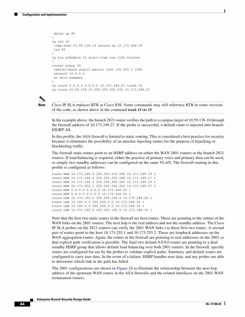
Configuration and Implementation
delay up 90!ip sla 15 icmp-echo 10.59.136.10 source-ip 10.173.249.25 tos 46!ip sla schedule 15 start-time now life forever!router eigrp 30 redistribute static metric 1500 100 255 1 1500 network 10.0.0.0 no auto-summary!ip route 0.0.0.0 0.0.0.0 10.173.249.27 track 15ip route 10.59.136.10 255.255.255.255 10.173.249.27
Note Cisco IP SLA replaces RTR in Cisco IOS. Some commands may still reference RTR in some versions of the code, as shown above in the command track 15 rtr 15.
In the example above, the branch 2821 router verifies the path to a campus target of 10.59.136.10 through the firewall address of 10.173.249.27. If the probe is successful, a default route is injected into branch EIGRP AS.
In this profile, the ASA firewall is limited to static routing. This is considered a best practice for security because it eliminates the possibility of an attacker injecting routes for the purpose of hijacking or blackholing traffic.
The firewall static routes point to an HSRP address on either the WAN 2801 routers or the branch 2821 routers. If load balancing is required, either the practice of primary voice and primary data can be used, or simply two standby addresses can be configured on the same VLAN. The firewall routing in this profile is configured as follows:
route WAN 10.173.249.8 255.255.255.248 10.173.249.18 1route WAN 10.173.249.0 255.255.255.248 10.173.249.17 1route WAN 10.173.255.2 255.255.255.255 10.173.249.18 1route WAN 10.173.255.1 255.255.255.255 10.173.249.17 1route WAN 0.0.0.0 0.0.0.0 10.173.249.22 1route WAN 0.0.0.0 0.0.0.0 10.173.249.20 1route LAN 10.173.192.0 255.255.192.0 10.173.249.29 1route LAN 10.100.0.0 255.255.0.0 10.173.249.29 1route LAN 10.100.0.0 255.255.0.0 10.173.249.30 1route LAN 10.173.192.0 255.255.192.0 10.173.249.30 1
Note that the first two static routes in the firewall are host routes. These are pointing to the subnet of the WAN links on the 2801 routers. The next hop is the real address and not the standby address. The Cisco IP SLA probes on the 2821 routers can verify the 2801 WAN links via these first two routes. A second pair of routes point to the host 10.173.255.1 and 10.173.255.2. These are loopback addresses on the WAN aggregation router. Again, the routes in the firewall are pointing to real addresses on the 2801 so that explicit path verification is possible. The final two default 0.0.0.0 routes are pointing to a dual standby HSRP group that allows default load balancing over both 2801 routers. In the firewall, specific routes are configured for use by the probes to validate explicit paths. Summary and default routes are configured to carry user data. In the event of a failure, HSRP handles user data, and any probes are able to determine which link in the path has failed.
The 2801 configurations are shown in Figure 26 to illustrate the relationship between the next hop address of the upstream WAN routes in the ASA firewalls and the related interfaces on the 2801 WAN termination routers.
44Enterprise Branch Security Design Guide
OL-11726-01
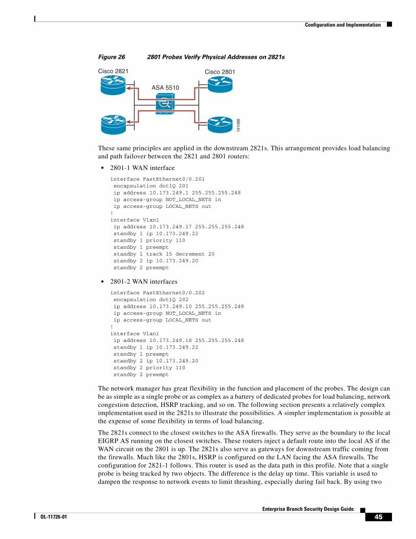
Configuration and Implementation
Figure 26 2801 Probes Verify Physical Addresses on 2821s
These same principles are applied in the downstream 2821s. This arrangement provides load balancing and path failover between the 2821 and 2801 routers:
• 2801-1 WAN interface
interface FastEthernet0/0.201 encapsulation dot1Q 201 ip address 10.173.249.1 255.255.255.248 ip access-group NOT_LOCAL_NETS in ip access-group LOCAL_NETS out!interface Vlan1 ip address 10.173.249.17 255.255.255.248 standby 1 ip 10.173.249.22 standby 1 priority 110 standby 1 preempt standby 1 track 15 decrement 20 standby 2 ip 10.173.249.20 standby 2 preempt
• 2801-2 WAN interfaces
interface FastEthernet0/0.202 encapsulation dot1Q 202 ip address 10.173.249.10 255.255.255.248 ip access-group NOT_LOCAL_NETS in ip access-group LOCAL_NETS out!interface Vlan1 ip address 10.173.249.18 255.255.255.248 standby 1 ip 10.173.249.22 standby 1 preempt standby 2 ip 10.173.249.20 standby 2 priority 110 standby 2 preempt
The network manager has great flexibility in the function and placement of the probes. The design can be as simple as a single probe or as complex as a battery of dedicated probes for load balancing, network congestion detection, HSRP tracking, and so on. The following section presents a relatively complex implementation used in the 2821s to illustrate the possibilities. A simpler implementation is possible at the expense of some flexibility in terms of load balancing.
The 2821s connect to the closest switches to the ASA firewalls. They serve as the boundary to the local EIGRP AS running on the closest switches. These routers inject a default route into the local AS if the WAN circuit on the 2801 is up. The 2821s also serve as gateways for downstream traffic coming from the firewalls. Much like the 2801s, HSRP is configured on the LAN facing the ASA firewalls. The configuration for 2821-1 follows. This router is used as the data path in this profile. Note that a single probe is being tracked by two objects. The difference is the delay up time. This variable is used to dampen the response to network events to limit thrashing, especially during fail back. By using two
1910
88
Cisco 2821 Cisco 2801
ASA 5510
45Enterprise Branch Security Design Guide
OL-11726-01

Configuration and Implementation
objects, it is possible to time events so the network fails back in an orderly fashion. In this case, object 15 is used to place the default route into the local AS, and object 20 is used to adjust the HSRP priority used by the downstream firewalls. The objective is to ensure that the upstream path of the client is in place before accepting downstream traffic from the firewalls. This is optional, and the following configuration snippet from 2821-is shown to detail possible configurations:
track 15 rtr 15 delay up 90!track 20 rtr 15 delay up 95!interface GigabitEthernet1/0.1 encapsulation dot1Q 206 ip address 10.173.249.25 255.255.255.248 no snmp trap link-status standby 1 ip 10.173.249.30 standby 1 priority 110 standby 1 preempt standby 1 track 20 decrement 20 standby 2 ip 10.173.249.29 standby 2 preempt!router eigrp 30 redistribute static metric 1500 100 255 1 1500 network 10.0.0.0 no auto-summary no eigrp log-neighbor-warnings!ip sla 15 icmp-echo 10.59.136.10 source-ip 10.173.249.25 tos 46!ip sla schedule 15 life forever start-time now!ip route 0.0.0.0 0.0.0.0 10.173.249.27 track 15ip route 10.59.136.10 255.255.255.255 10.173.249.27ip route 10.173.249.16 255.255.255.248 10.173.249.27
The other 2821 in this profile is used to pass voice traffic. This is done by adjusting the EIGRP delay on the VoIP subnets and setting the HSRP priority to match. The dual-tier topology explains this approach. The focus of this section is to show how Object Tracking can be used to ensure that the path delay is meeting established thresholds.If the threshold is exceeded, the traffic can be rerouted over the other 2821 serving the data traffic. Because the first 2821 serves as the last ditch effort for voice, no path delay requirements are set. Although it is not shown here, it is possible to set up two probes over either explicit path and then inject routes into the local AS with differing administrative distances. The probe does not check the end-to-end delay to all possible RTP destinations. Instead, the probe is set to check the WAN delay associated with this particular branch. (See Figure 27.)
46Enterprise Branch Security Design Guide
OL-11726-01
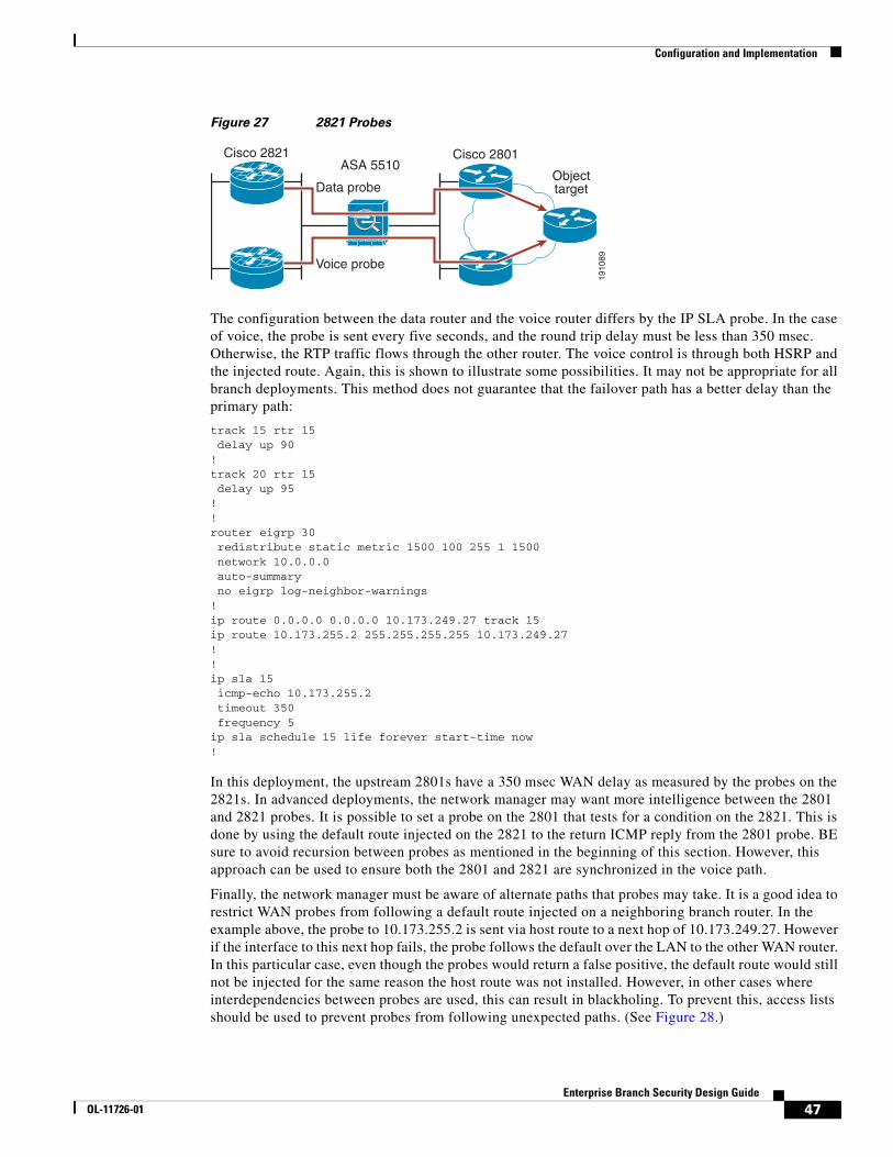
Configuration and Implementation
Figure 27 2821 Probes
The configuration between the data router and the voice router differs by the IP SLA probe. In the case of voice, the probe is sent every five seconds, and the round trip delay must be less than 350 msec. Otherwise, the RTP traffic flows through the other router. The voice control is through both HSRP and the injected route. Again, this is shown to illustrate some possibilities. It may not be appropriate for all branch deployments. This method does not guarantee that the failover path has a better delay than the primary path:
track 15 rtr 15 delay up 90!track 20 rtr 15 delay up 95!!router eigrp 30 redistribute static metric 1500 100 255 1 1500 network 10.0.0.0 auto-summary no eigrp log-neighbor-warnings!ip route 0.0.0.0 0.0.0.0 10.173.249.27 track 15ip route 10.173.255.2 255.255.255.255 10.173.249.27!!ip sla 15 icmp-echo 10.173.255.2 timeout 350 frequency 5ip sla schedule 15 life forever start-time now!
In this deployment, the upstream 2801s have a 350 msec WAN delay as measured by the probes on the 2821s. In advanced deployments, the network manager may want more intelligence between the 2801 and 2821 probes. It is possible to set a probe on the 2801 that tests for a condition on the 2821. This is done by using the default route injected on the 2821 to the return ICMP reply from the 2801 probe. BE sure to avoid recursion between probes as mentioned in the beginning of this section. However, this approach can be used to ensure both the 2801 and 2821 are synchronized in the voice path.
Finally, the network manager must be aware of alternate paths that probes may take. It is a good idea to restrict WAN probes from following a default route injected on a neighboring branch router. In the example above, the probe to 10.173.255.2 is sent via host route to a next hop of 10.173.249.27. However if the interface to this next hop fails, the probe follows the default over the LAN to the other WAN router. In this particular case, even though the probes would return a false positive, the default route would still not be injected for the same reason the host route was not installed. However, in other cases where interdependencies between probes are used, this can result in blackholing. To prevent this, access lists should be used to prevent probes from following unexpected paths. (See Figure 28.)
1910
89
Cisco 2821 Cisco 2801
Data probe
Voice probe
Objecttarget
ASA 5510
47Enterprise Branch Security Design Guide
OL-11726-01
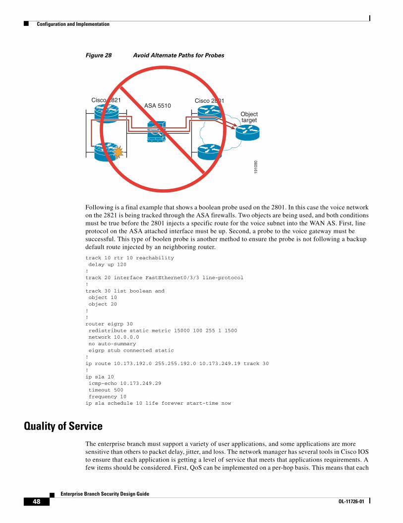
Configuration and Implementation
Figure 28 Avoid Alternate Paths for Probes
Following is a final example that shows a boolean probe used on the 2801. In this case the voice network on the 2821 is being tracked through the ASA firewalls. Two objects are being used, and both conditions must be true before the 2801 injects a specific route for the voice subnet into the WAN AS. First, line protocol on the ASA attached interface must be up. Second, a probe to the voice gateway must be successful. This type of boolen probe is another method to ensure the probe is not following a backup default route injected by an neighboring router.
track 10 rtr 10 reachability delay up 120!track 20 interface FastEthernet0/3/3 line-protocol!track 30 list boolean and object 10 object 20!!router eigrp 30 redistribute static metric 15000 100 255 1 1500 network 10.0.0.0 no auto-summary eigrp stub connected static!ip route 10.173.192.0 255.255.192.0 10.173.249.19 track 30!ip sla 10 icmp-echo 10.173.249.29 timeout 500 frequency 10ip sla schedule 10 life forever start-time now
Quality of Service The enterprise branch must support a variety of user applications, and some applications are more sensitive than others to packet delay, jitter, and loss. The network manager has several tools in Cisco IOS to ensure that each application is getting a level of service that meets that applications requirements. A few items should be considered. First, QoS can be implemented on a per-hop basis. This means that each
1910
90
Cisco 2821 Cisco 2801
Objecttarget
ASA 5510
48Enterprise Branch Security Design Guide
OL-11726-01
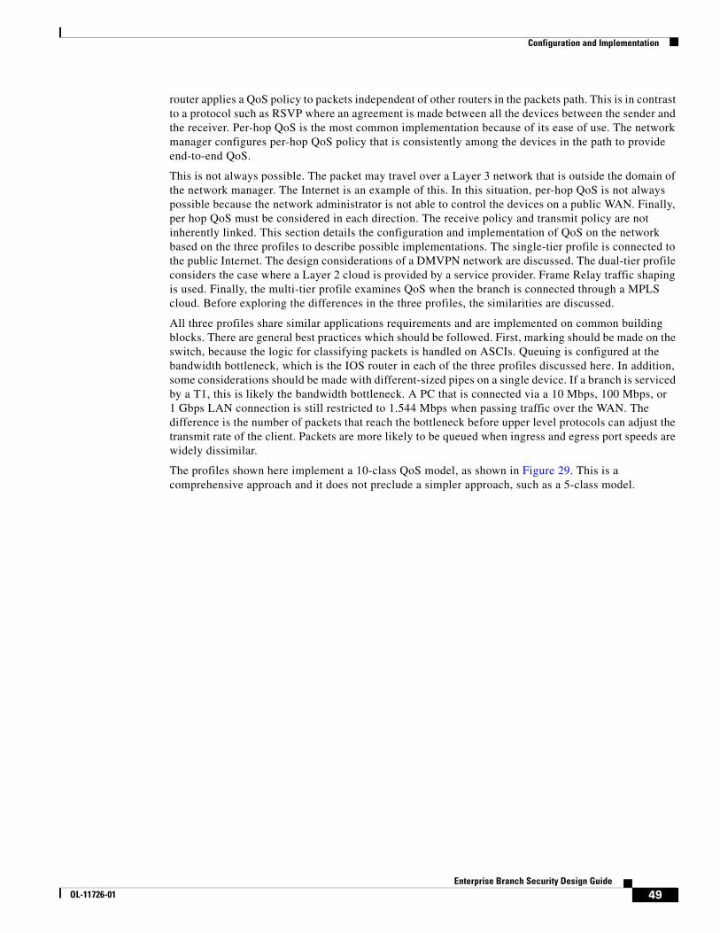
Configuration and Implementation
router applies a QoS policy to packets independent of other routers in the packets path. This is in contrast to a protocol such as RSVP where an agreement is made between all the devices between the sender and the receiver. Per-hop QoS is the most common implementation because of its ease of use. The network manager configures per-hop QoS policy that is consistently among the devices in the path to provide end-to-end QoS.
This is not always possible. The packet may travel over a Layer 3 network that is outside the domain of the network manager. The Internet is an example of this. In this situation, per-hop QoS is not always possible because the network administrator is not able to control the devices on a public WAN. Finally, per hop QoS must be considered in each direction. The receive policy and transmit policy are not inherently linked. This section details the configuration and implementation of QoS on the network based on the three profiles to describe possible implementations. The single-tier profile is connected to the public Internet. The design considerations of a DMVPN network are discussed. The dual-tier profile considers the case where a Layer 2 cloud is provided by a service provider. Frame Relay traffic shaping is used. Finally, the multi-tier profile examines QoS when the branch is connected through a MPLS cloud. Before exploring the differences in the three profiles, the similarities are discussed.
All three profiles share similar applications requirements and are implemented on common building blocks. There are general best practices which should be followed. First, marking should be made on the switch, because the logic for classifying packets is handled on ASCIs. Queuing is configured at the bandwidth bottleneck, which is the IOS router in each of the three profiles discussed here. In addition, some considerations should be made with different-sized pipes on a single device. If a branch is serviced by a T1, this is likely the bandwidth bottleneck. A PC that is connected via a 10 Mbps, 100 Mbps, or 1 Gbps LAN connection is still restricted to 1.544 Mbps when passing traffic over the WAN. The difference is the number of packets that reach the bottleneck before upper level protocols can adjust the transmit rate of the client. Packets are more likely to be queued when ingress and egress port speeds are widely dissimilar.
The profiles shown here implement a 10-class QoS model, as shown in Figure 29. This is a comprehensive approach and it does not preclude a simpler approach, such as a 5-class model.
49Enterprise Branch Security Design Guide
OL-11726-01
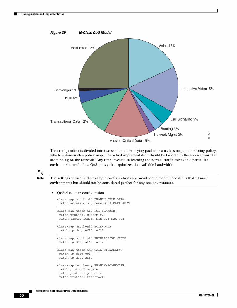
Configuration and Implementation
Figure 29 10-Class QoS Model
The configuration is divided into two sections: identifying packets via a class map; and defining policy, which is done with a policy map. The actual implementation should be tailored to the applications that are running on the network. Any time invested in learning the normal traffic mixes in a particular environment results in a QoS policy that optimizes the available bandwidth.
Note The settings shown in the example configurations are broad scope recommendations that fit most environments but should not be considered perfect for any one environment.
• QoS class map configuration
class-map match-all BRANCH-BULK-DATA match access-group name BULK-DATA-APPS!class-map match-all SQL-SLAMMER match protocol custom-02 match packet length min 404 max 404!class-map match-all BULK-DATA match ip dscp af11 af12!class-map match-all INTERACTIVE-VIDEO match ip dscp af41 af42!class-map match-any CALL-SIGNALLING match ip dscp cs3 match ip dscp af31!class-map match-any BRANCH-SCAVENGER match protocol napster match protocol gnutella match protocol fasttrack
Bulk 4%
Transactional Data 12%
Scavenger 1%
Voice 18%Best Effort 25%
Call Signaling 5%
Interactive Video15%
Routing 3%
Network Mgmt 2%
Mission-Critical Data 15%
1910
91
50Enterprise Branch Security Design Guide
OL-11726-01

Configuration and Implementation
match protocol kazaa2!class-map match-all NET-MGMG match ip dscp af21 af22!class-map match-any BRANCH-TRANSACTIONAL-DATA match protocol citrix match protocol ldap match protocol sqlnet match protocol http url "*cisco.com" match protocol custom-01!class-map match-all BRANCH-MISSION-CRITICAL match access-group name MISSION-CRITICAL-SERVERS!class-map match-any WORMS match protocol http url "*.ida*" match protocol http url "*cmd.exe*" match protocol http url "*root.exe*" match protocol http url "*readme.eml*" match class-map SQL-SLAMMER match protocol exchange match protocol netbios match protocol custom-03!class-map match-all VOICE match ip dscp ef match ip precedence 5!class-map match-all MISSION-CRITICAL-DATA match ip dscp 25!class-map match-any BRANCH-NET-MGMT match protocol snmp match protocol syslog match protocol telnet match protocol nfs match protocol dns match protocol icmp match protocol tftp!class-map match-all ROUTING match ip dscp cs6!class-map match-all SCAVENGER match ip dscp cs1
• QoS policy map configurations
policy-map BRANCH-LAN-EDGE-OUT class CLASS-DEFAULT set cos dscp!policy-map BRANCH-LAN-EDGE-IN class BRANCH-MISSION-CRITICAL set ip dscp 25 class BRANCH-TRANSACTIONAL-DATA set ip dscp af21 class BRANCH-NET-MGMT set ip dscp cs2 class BRANCH-BULK-DATA set ip dscp af11 class BRANCH-SCAVENGER set ip dscp cs1
51Enterprise Branch Security Design Guide
OL-11726-01
Configuration and Implementation
class WORMS drop class CLASS-DEFAULT set ip dscp default!policy-map BRANCH-WAN-EDGE class VOICE priority percent 18 class INTERACTIVE-VIDEO priority percent 15 class CALL-SIGNALLING bandwidth percent 5 class ROUTING bandwidth percent 3 class NET-MGMG bandwidth percent 2 class MISSION-CRITICAL-DATA bandwidth percent 12 random-detect dscp-based class BULK-DATA bandwidth percent 4 random-detect dscp-based class SCAVENGER bandwidth percent 1 class CLASS-DEFAULT bandwidth percent 25 random-detect
After the classes and policy maps are defined, they are applied to specific interfaces. More details on the WAN QoS settings are given toward the end of this section in the profile-specific discussions. The following is the general configuration on the LAN interfaces:
• QoS configurations on LAN interfaces
interface GigabitEthernet1/0.193 ! description data vlan for pcs encapsulation dot1Q 193 ip address 10.173.193.1 255.255.255.128service-policy input BRANCH-LAN-EDGE-IN service-policy output BRANCH-LAN-EDGE-OUT!interface GigabitEthernet1/0.200 ! description voice vlan for phonesencapsulation dot1Q 200 ip address 10.173.1.129 255.255.255.128service-policy output BRANCH-LAN-EDGE-OUT!
The usage of most of the ten classes is apparent by their descriptive names. However, a few classes are detailed to highlight their function or use.
First, consider the class shown above called worms. This classification is useful to prevent the breakout of a known worm. Packets that match these known profiles are dropped. As new worms are discovered, their profiles can easily be added to this class map. To be effective, a tool or script needs to apply the configuration changes to the branch routers when the network grows beyond more than a few dozen branches.
Another class map of interest is the scavenger class. This class may not be immediately apparent. This traffic is legitimate network traffic but is given less than default priority. This traffic has no business value to enterprise objectives. Quite often it is used to transport entertainment applications such as online gaming. This traffic can be squelched when the network begins to congest but still allows the traffic when the network is idle. This classification is one step above denying the traffic completely with an access
52Enterprise Branch Security Design Guide
OL-11726-01
Configuration and Implementation
list. Perhaps a more important application of the scavenger class is mark down. This is the practice to remarking network traffic that is well in excess of normal profiles with a marking of CS1. Because most worms disguise themselves as legitimate traffic, it is difficult to block them with an access list. Instead, the packets are marked down when their flows rates are above what is expected. As a simple example, DNS queries of 1000 pps from a single port would exceed normal rates. In this situation, the scavenger class can be very effective in preventing worms and DDoS attacks from adversely affecting other traffic. In addition, this effectively slows the ability of a worm to infect other hosts.
• Typical mark down configuration on a 3750 Catalyst switch
mls qos map policed-dscp 0 10 18 24 25 34 to 8!policy-map IPPHONE+PC class VVLAN-VOICE set dscp ef police 128000 8000 exceed-action drop class VVLAN-CALL-SIGNALLING set dscp cs3 police 32000 8000 exceed-action policed-dscp-transmit class VVLAN-ANY set dscp default police 32000 8000 exceed-action policed-dscp-transmit class DVLAN-PC-VIDEO set dscp af41 police 48000 8000 exceed-action policed-dscp-transmit class DVLAN-MISSION-CRITICAL-DATA set dscp 25 police 5000000 8000 exceed-action policed-dscp-transmit class DVLAN-TRANSACTIONAL-DATA set dscp af21 police 5000000 8000 exceed-action policed-dscp-transmit class DVLAN-BULK-DATA set dscp af11 police 5000000 8000 exceed-action policed-dscp-transmit!
On the other end of the service spectrum is Real-Time Protocol (RTP) traffic, which requires low delay and low jitter. It is carried in a priority queue rather than a bandwidth queue. Priority queues are serviced in a fashion similar to jumping ahead in line. Bandwidth queues are serviced in a round robin fashion so that each queue realizes a throughput equivalent to the configured bandwidth. The RTP queue represents the highest level of QoS available on the network and is typically reserved for voice traffic. Because these queues provide the highest QoS, they should be protected against misuse by either malicious users or misconfiguration. A trust boundary is established as close to the edge of the network as possible. There are three possible modes: trusted, untrusted, or conditionally trusted. In a conditionally trusted model, a certain devices such as Cisco IP phones are trusted while unidentified clients are not. Furthermore, a phone may be trusted while a PC connected to the phone is not. This is known as an extended trust boundary. The switch resets the DSCP value to 0 on any device that is not trusted. The DSCP value on packets from trusted devices is not altered.
Note After mls qos is configured, all ports default to an untrusted state. Before ip mls qos is configured, all ports are trusted and the DSCP values are not rewritten. Therefore, mls qos must be configured to enable QoS on the Catalyst switches.
• Common components of a QoS configuration
mls qos!interface GigabitEthernet1/0/8! description phone with PC connected to phone
53Enterprise Branch Security Design Guide
OL-11726-01

Configuration and Implementation
switchport access vlan 102 switchport mode access switchport voice vlan 101 mls qos trust device cisco-phone!
Network managers should be aware of a few more QoS settings unique to the Catalyst switch, such as the shaped round robin (srr) queues. Understanding these queues is important when determining how the various queues in a Catalyst switch are used. The discussion that follows applies to the 3750 used in these profiles. Other switches such as the 3550 are configured differently, so the QoS Configuration guide should be consulted to facilitate a proper QoS configuration, which is available at the following URL: http://www.cisco.com/en/US/products/sw/iosswrel/ps1835/products_configuration_guide_book09186a00800c5e31.html
There are four ssr-queues on the 3750. Queue 1 is a priority queue that is serviced before queues 2–4, which are weighted tail drop queues. Higher priority traffic such as voice is place in Q1 while lower priority traffic such as scavenger is placed in Q4. Within each queue, four thresholds determine how packets are dropped when the queue is under congestion. The configuration allows the binary of a DSCP value to be placed in a queue with a threshold setting. For example, mls qos srr-queue output dscp-map queue 2 threshold 2 24 26 places call signaling packets in queue 2 at the second threshold. When the queue depth exceeds this thresholds, these packets are eligible for discard. Packets can be assigned to an ssr-queue by either reference to DSCP or CoS settings. The default thresholds for the queues do not need adjusting to apply these maps, with the exception of Q2, where threshold 1 is set to 70 percent and threshold 2 is set to 80 percent; and Q4, where threshold 1 is set to 40 percent. The recommend settings for SRR queues in the branch switches are as follows:
mls qos srr-queue output cos-map queue 1 threshold 3 5mls qos srr-queue output cos-map queue 2 threshold 1 2 4mls qos srr-queue output cos-map queue 2 threshold 2 3mls qos srr-queue output cos-map queue 2 threshold 3 6 7mls qos srr-queue output cos-map queue 3 threshold 3 0mls qos srr-queue output cos-map queue 4 threshold 3 1mls qos srr-queue output dscp-map queue 1 threshold 3 46mls qos srr-queue output dscp-map queue 2 threshold 1 16 18 20 22 25 32 3mls qos srr-queue output dscp-map queue 2 threshold 1 38mls qos srr-queue output dscp-map queue 2 threshold 2 24 26mls qos srr-queue output dscp-map queue 2 threshold 3 48 56mls qos srr-queue output dscp-map queue 3 threshold 3 0mls qos srr-queue output dscp-map queue 4 threshold 1 8mls qos srr-queue output dscp-map queue 4 threshold 3 10 12 14mls qos queue-set output 1 threshold 2 70 80 100 100mls qos queue-set output 1 threshold 4 40 100 100 100
After the global srr-queues are set up, they can be used on the switch interfaces. The commands shape the priority queue to one-third of the bandwidth. The remaining 66 percent bandwidth is shared at 70 percent for Q2, 25 percent for Q3, and 5 percent for Q4.
The recommended SRR interface settings are as follows:
!interface GigabitEthernet1/0/8! description phone with PC connected to phone srr-queue bandwidth share 1 70 25 5 srr-queue bandwidth shape 3 0 0 0 priority-queue out
The following sections detail specific QoS concerns with the three profiles used in this guide. They are focused around the differences in WAN transport because this represents the bandwidth bottleneck in most deployments.
54Enterprise Branch Security Design Guide
OL-11726-01
Configuration and Implementation
Single-Tier Profile
The single-tier branch profile is attached to the Internet with a dedicated T1 circuit. An ADSL connection is used to provide a backup link. The Internet presents some challenges for QoS, not only because of the lack of support, but also because encryption is often used. Encryption does not tolerate out of order packets. IPsec considers this condition to indicate someone may have tampered with the packets. Another challenge is classifying packets where the header is not visible to the interface queuing mechanism because it has been encrypted. Cisco IOS provides a feature known as QoS-preclassify to handle this situation.
mGRE virtual interfaces do not support shaping or fancy queuing; however, GRE and VTI interfaces do. Service policies can be applied to the physical interface. Although the packet is already encrypted at this point, the DSCP values are copied forward into the crypto header and are available to the service policy on the physical interface. Some QoS is possible at this level. One limitation is that all crypto packets are sequenced, so re-ordering a stream of packets to preference those marked with DSCP 46 can cause drops. Voice over a DMVPN network should also be approached with caution. This type of network is possible, but while the spoke-to-spoke (S-S) path is being set up, RTP packets are switched through the hub. When the S-S crypto path is cut over, the first few packets on this path can arrive before the trailing packets on the spoke-hub-spoke (S-H-S) path, resulting in discards at the phone. G.729 is more susceptible to this than is G.711, especially if the difference in path delay exceeds 25 msec.
Dual-Tier Profile
The dual-tier profile uses a legacy Frame Relay WAN. It is repeated here for completeness. One additional point relates to a design where voice and data are carried on differing primary paths but use a common path during a circuit failure. There is a compelling argument to optimize QoS based on the typically traffic mix. However, the worst case must also be considered where voice and data are sharing the same bandwidth link. It is during this time that QoS is most likely to be engaged. Therefore, the best practice is to configure both circuits with similar policies with the assumption that they will both carry a mix of voice and data.
The configuration on the WAN link of both the primary data and primary voice router is as follows:
policy-map BRANCH-WAN-EDGE class VOICE priority percent 18 class INTERACTIVE-VIDEO priority percent 15 class CALL-SIGNALLING bandwidth percent 5 class ROUTING bandwidth percent 3 class NET-MGMG bandwidth percent 2 class MISSION-CRITICAL-DATA bandwidth percent 12 random-detect dscp-based class BULK-DATA bandwidth percent 4 random-detect dscp-based class SCAVENGER bandwidth percent 1 class CLASS-DEFAULT bandwidth percent 25 random-detect!policy-map WAN_EDGE_FRTS class CLASS-DEFAULT
55Enterprise Branch Security Design Guide
OL-11726-01
Configuration and Implementation
shape average 1460000 14600 0 service-policy BRANCH-WAN-EDGE!interface Serial0/0/0 bandwidth 1544 no ip address encapsulation frame-relay!interface Serial0/0/0.17 point-to-point bandwidth 1544 ip address 10.173.199.2 255.255.255.252frame-relay interface-dlci 17 class FRAME_MAP_T1!map-class frame-relay FRAME_MAP_T1 service-policy output WAN_EDGE_FRTS!
Multi-Tier Profile
The multi-tier branch profile consists of two 2801 routers that are connected to a service provider-provided MPLS VPN service. The 2801s provide a CE functionality. QoS is applied on the link from the CE to the PE. Service providers that offer SLA also support QoS in the direction from the PE towards the CE. Cisco has certified Cisco Powered Networks (CPN) service providers to meet SLA requirements. A list of these providers can be found at the following URL: http://www.cisco.com/pcgi-bin/cpn/cpn_pub_bassrch.pl
An MPLS cloud likely supports only a small number of classes. Some typically offered classes are real-time, critical-data, and best effort. The admission criterion for a particular CoS is the appropriate DSCP values. Therefore, the challenge for the network manager is to collapse a 10-class model into a 2-, 3-, or 4-class model. The following general guidelines should be followed when mixing different types of traffic into the available SLA classifications:
• Provide call signalling with the same level as RTP.
Call signalling packets are small, and the number of packets per second are trivial and as such, consume little bandwidth. These packets are part of the network control plane, and proper call handling requires these packets get preferential treatment over other critical data.
• Avoid mixing UDP and TCP packets into the same classification.
Although some UDP applications implement a back off algorithm, some do not. Because all TCP does allow the transmitter to be throttled, there is a risk that unthrottled UDP can starve TCP traffic.
• Bulk data presents a unique challenge because of its ability to saturate whichever queue it is assigned. Typically, this ends up in the best effort queue. However, the network manager must also be aware of other flows that compete for bandwidth.
Another unique aspect of QoS over MPLS is that the remark traffic of the service provider that exceeds the service level as allowed by DiffServ standards such as RFC2597. It can be a challenge in an end-to-end QoS model where marking is typically done on the edge. In this situation, it is possible to remark traffic back into the previous classifications. It is also possible to remark traffic ingress towards the branch from the 3- or 4-class model imposed by the service provider back into the 10-class model. This is not typical because the ingress circuit represents the bandwidth bottleneck. Remarking back into a 10-class model is likely done on the WAN aggregation routers located at the campus.
56Enterprise Branch Security Design Guide
OL-11726-01
Configuration and Implementation
The service provider also limits the committed bandwidth to below the interface speed. If the CE device is attached to the MPLS network via a 100 Mbps Ethernet interface, yet only allows 2 Mbps of actual traffic, then hierarchical CBWFQ can be used. This approach allows queuing of packets within a shaped rate. The shaper provides logical congestion in place of the physical congestion feedback provided when the buffers on a serial interface fill.
The multi-tier branch profile QoS configuration is as follows:
policy-map BRANCH-WAN-EDGE class VOICE priority percent 18 class INTERACTIVE-VIDEO priority percent 15 class CALL-SIGNALING bandwidth percent 5 class ROUTING bandwidth percent 3 class NET-MGMT bandwidth percent 2 class MISSION-CRITICAL-DATA bandwidth percent 15 random-detect class TRANSACTIONAL-DATA bandwidth percent 12 random-detect dscp-based class BULK-DATA bandwidth percent 4 random-detect dscp-based class SCAVENGER bandwidth percent 1 class class-default bandwidth percent 25 random-detect!!interface FastEthernet0/0max-reserved-bandwidth 100service-policy output BRANCH-WAN-EDGE
Security ServicesSecurity services ensure that all aspects of the network are protected from devices connecting to the network to secure transport and protect against data theft. Network security is crucial in modern networks. Protecting a device from attack in a network is discussed in Infrastructure Protection, page 19. Making sure the data traversing from the branch to the campus or headquarters is secure and confidential is discussed in Secure Connectivity, page 20. Threat Defense Detection and Mitigation, page 21 discusses how to avoid unwanted traffic such as viruses, worms, and attacks, from entering a network and mitigating any traffic that slips through the cracks. A branch network that provides infrastructure protection, secure connectivity, and threat defense mechanisms is a great foundation to overlay advanced security services, such as identity. All three profiles provide such a security baseline for the branch network.
Infrastructure Protection
Infrastructure protection provides proactive measures to protect the infrastructure devices; in this case, Cisco IOS Software-based routers, switches, and appliances, from direct attacks. This section covers the key features that are required to prevent unwanted users accessing a device in a network. Rather than
57Enterprise Branch Security Design Guide
OL-11726-01
Configuration and Implementation
discussing these features on a per-profile basis as with other services in this design chapter, configurations are separated into access routers, switches, and the Cisco ASA appliance. Regardless of the profile, the infrastructure protection are layers of security that in combination ward off unauthorized access and provide the network administrator a historical audit trail of the branch devices.
Turning Off Unnecessary Services
Cisco recommends disabling all known and potentially hazardous and unused features in a network. Some of these features are directed broadcasts, IP redirects, IP proxy-ARP, finger, CDP, small services, and the built-in global HTTP daemon in Cisco IOS Software.
The following configurations are used in all three profiles to turn off unnecessary services on a device:
• Cisco IOS access router
no service pad! no ip source-routeno ip bootp serverno ip domain lookup!interface XXX no ip redirects no ip unreachables no ip proxy-arp!no ip http server
• Cisco Catalyst switch
no service pad!no ip domain-lookup!no ip http server
• Cisco ASA Appliance—These features are not enabled on an ASA, so no action is required.
Enabling Logging
On Cisco access routers, switches, or appliances, the “log” statement in the access list can cause the system to go into process switch mode for logging on an access list line match. A prolonged high CPU utilization can cause the network to become unstable and unavailable. To mitigate this problem, it is strongly recommended configuring the use of logging commands available in Cisco IOS to help contain the amount of logging per second done by the device with the access list.
The following configurations are used in all three profiles to enable logging on a device:
• Cisco IOS access router
service timestamps debug datetime msecservice timestamps log datetime localtime!logging countlogging buffered 8192 debugginglogging rate-limit 5
• Cisco Catalyst switch
service timestamps debug uptimeservice timestamps log uptime!logging count
58Enterprise Branch Security Design Guide
OL-11726-01
Configuration and Implementation
logging buffered 8192 debugginglogging rate-limit 5
• Cisco ASA Appliance
logging enablelogging buffered emergencieslogging asdm informational
Enable SSH instead of Telnet for Remote Administration
Cisco recommends using SSH instead of Telnet for remote administration of devices. SSH provides an encryption shell to prevent snooping by unwanted parties and authentication. SSH shell sessions are encrypted, whereas Telnet is in clear text. Passwords and any data transferred from a user accessing a device is private and not easily viewable.
The following configurations are used in all three profiles to enable SSH on a device:
• Cisco IOS access router
hostname access-routerip domain name ese.cisco.com!cry key generate rsa general-keys modulus 1024!ip ssh version 2ip ssh time-out 60ip ssh authentication-retries 2ip ssh source-interface GigabitEthernet0/1!line vty0 15Transport input ssh
• Cisco Catalyst switch
hostname catalyst-switchip domain name ese.cisco.com!cry key generate rsa general-keys modulus 1024!ip ssh version 2ip ssh time-out 60ip ssh authentication-retries 2ip ssh source-interface Vlan193!!line vty 0 15Transport input ssh
• Cisco ASA Appliance
hostname asa-appliancedomain-name ese.cisco.com!cry key generate rsa modulus 1024!ssh timeout 5
59Enterprise Branch Security Design Guide
OL-11726-01
Configuration and Implementation
Enabling HTTPS Server
Introduced in Cisco IOS Software Release 11.2, the Cisco IOS Software web browser user interface allows the configuration of Cisco IOS Software-based devices by using a web browser such as Internet Explorer or Netscape. This user interface relies on a built-in HTTP(S) server that runs on Cisco IOS Software. The Secure HTTP (HTTPS) feature provides the capability to connect the Cisco IOS Software web server securely. This feature uses Secure Sockets Layer (SSL) and Transport Layer Security (TLS) to provide device authentication and data encryption.
The following configurations are used in all three profiles to enable HTTPS Server on a device:
• Cisco IOS access router
ip http secure-server!
• Cisco Catalyst switch
ip http secure-server!
• Cisco ASA Appliance
http server enablehttp 192.168.1.0 255.255.255.0 managementhttp 64.102.0.0 255.255.0.0 management
Controlling VTY and Console Lines
VTY and console ports should be configured to accept connections only with the protocols actually needed. Another good practice is the use of the access-class command to restrict the IP addresses from which the VTY or console port accept connections. By default, after an access protocol is enabled on a VTY line, any host can initiate a connection using that protocol. The access-class command defines a list of hosts or networks from which access is allowed that prevents unauthorized access from untrusted sources. This practice also helps mitigate a DoS attack on the VTY lines. Another useful tactic is to decrease the VTY timeouts using the exec-timeout command. This command prevents an idle session from consuming a VTY indefinitely. By default, a VTY session has a 10-minute timeout.
The following configurations are used in all three profiles to control VTY and console lines on a device:
• Cisco IOS access router
line con 0 transport output all!line aux 0transport output all!line vty 0 4 password 7 1511021F0725 exec prompt timestamp transport input ssh transport output all
• Cisco Catalyst switch
line con 0transport output all!line vty 0 4 exec-timeout 60 0 password 7 02050D480809
60Enterprise Branch Security Design Guide
OL-11726-01
Configuration and Implementation
exec prompt timestamp transport input ssh!line vty 5 15 password 7 02050D480809 exec prompt timestamp transport inputssh
• Cisco ASA Appliance
ssh 1.1.1.0 255.0.0.0 dmz 1ssh 2.0.0.0 255.255.0.0 insidessh scopy enable(enter a line for each subnet that is allowed SSH access)!ssh timeout 5console timeout 0
Password Management
Cisco recommends that AAA be used on all devices to provide authentication, command authorization, and CLI accounting on administrative sessions. AAA with TACACS+ can provide an easy-to-manage source for device account administration and authorization commands. These AAA commands are used in conjunction with a Cisco Secure Access Control Server (ACS) or other TACACS+ server. The following are benefits of using AAA commands with an ACS server:
• Authentication (who you are)—Account UserID and password are stored in ACS for easy management and grouping abilities.
• Authorization (what are you allowed to do)—A downloadable authorization command set is served from ACS to the devices after a successful login to allow simplified control and easy grouping of administrative commands for devices.
• Accounting (record of what you did on which device and when it occurred)—The ACS server accounting screen has a command-by-command record of all commands issued on each device.
Failed attempts at authentication to the devices are kept as a record in the ACS server. Also, communications from the device to the ACS server (via TACACS+) use a hash algorithm, so it is not sent in clear text.
The following configurations are used in all three profiles for password management:
• Cisco IOS access router
service password-encryptionenable secret 5 $1$1ZoH$eUqctzD0NrObry5sgk/jz0!aaa new-model!aaa authentication login ssh_users group tacacs+aaa accounting send stop-record authentication failureaaa accounting exec ssh_users start-stop group tacacs+aaa accounting commands 7 ssh_users start-stop group tacacs!aaa session-id common!login block-for 30 attempts 3 within 200login delay 2!username cisco password 7 121A0C041104!ip tacacs source-interface Loopback0
61Enterprise Branch Security Design Guide
OL-11726-01
Configuration and Implementation
!tacacs-server host 10.59.138.11 single-connectiontacacs-server directed-requesttacacs-server key 7 13061E010803557878!
• Cisco Catalyst switch
version 12.2service password-encryptionenable password 7 110A1016141Daaa authentication login ssh_users group tacacs+aaa accounting send stop-record authentication failureaaa accounting exec ssh_users start-stop group tacacs+aaa accounting commands 7 ssh_users start-stop group tacacs!aaa session-id common!login block-for 30 attempts 3 within 200login delay 2!username cisco password 7 121A0C041104!ip tacacs source-interface Loopback0!tacacs-server host 10.59.138.11 single-connectiontacacs-server directed-request!tacacs-server key 7 13061E010803557878
• Cisco ASA Appliance
passwd 2KFQnbNIdI.2KYOU encrypted!aaa-server tacacs-group protocol tacacs+aaa-server tacacs-group host 10.59.138.11 key Ciscoaaa-server TACACS+ protocol tacacs+!aaa authentication enable console tacacs-group LOCALaaa authentication ssh console tacacs-group LOCALaaa authentication telnet consol tacacs-group LOCAL!aaa authentication serial console tacacs-group LOCAL!aaa authorization command tacacs-group LOCAL!aaa accounting telnet console tacacs-groupaaa accounting ssh console tacacs-groupaaa accounting command tacacs-group
Secure Connectivity
Secure connectivity protects against information theft or alteration of the end user data over untrusted mediums. There are various ways to ensure that the connection between a branch and campus is secure. Encrypting the traffic provides data privacy. The single-tier branch profile uses this secure connectivity option as well as providing a tunnelling mechanism to allow non-IP protocols to traverse an ISP Internet cloud to the campus. Providing data isolation from users is also a mechanism to secure connectivity between a branch and a campus. Frame Relay DLCIs or ATM permanent virtual circuits (PVCs) isolate user traffic across an entire Frame Relay or ATM cloud to guarantee that only specific traffic pertinent
62Enterprise Branch Security Design Guide
OL-11726-01
Configuration and Implementation
to the network is received at both the branch and the campus. MPLS also provides traffic separation across an MPLS cloud through VRFs. The dual-tier branch profile uses Frame Relay and the multi-tier branch profile uses MPLS.
Single-Tier Branch Profile
As stated in WAN Services, page 8, the single-tier branch profile has a T1 link as the primary with an ADSL link for backup. Both links traverse an untrusted ISP Internet cloud for connectivity to the campus. As such, a mechanism for data isolation and data privacy is required. A tunneling protocol is required for data isolation, and an encryption protocol is required for data encryption. There are various choices for this requirement, as defined in the IPsec VPN WAN Design Overview at the following URL: http://www.cisco.com/go/srnd
Multicast and dynamic routing can also be accomplished with direct encapsulation IPsec VPNs without DMVPN or mGRE complexity. In addition to multicast and dynamic routing, spoke-to-spoke connections are desired, and DMVPN is the optimal choice. With DMVPN, an mGRE tunnel provides the tunneling mechanism with IPsec as the encryption protocol. The DMVPN design guide provides a comprehensive look at the DMVPN technology as a whole, but is mainly focused on the WAN aggregation platforms. This design guide is located: http://www.cisco.com/go/srnd. The same principles apply to this profile but the focus is on the actual branch.
In the single-tier profile, two tunnels are configured for each WAN link to the campus. Tunnel 0 is sourced from the T1 link as its physical interface and Tunnel 1 uses the ADSL link. The configurations can apply to both a hub-and-spoke or spoke-to-spoke topology, as shown in the DMVPN design guide. The configurations used for secure connectivity for this profile are as follows:
crypto isakmp policy 1 encr 3des authentication pre-sharecrypto isakmp key secret address 0.0.0.0 0.0.0.0crypto isakmp keepalive 10!crypto ipsec transform-set BRB esp-3des esp-sha-hmaccrypto ipsec transform-set BRB-BACK esp-3des esp-sha-hmac!crypto ipsec profile DMVPN set transform-set BRB!crypto ipsec profile DMVPN-BACK set transform-set BRB-BACK!interface Tunnel0 ip address 10.173.129.15 255.255.255.0ip mtu 1400ip nhrp authentication secret ip nhrp map multicast dynamic ip nhrp map multicast 192.168.201.1 ip nhrp map 10.173.129.1 192.168.201.1 ip nhrp network-id 10203 ip nhrp nhs 10.173.129.1load-interval 30 delay 500tunnel source Serial0/0/0:0 tunnel mode gre multipoint tunnel key 123 tunnel protection ipsec profile DMVPN!interface Tunnel1 ip address 10.173.130.15 255.255.255.0ip mtu 1400ip nhrp authentication secret
63Enterprise Branch Security Design Guide
OL-11726-01
Configuration and Implementation
ip nhrp map multicast dynamic ip nhrp map 10.173.130.1 192.168.206.1 ip nhrp map multicast 192.168.206.1 ip nhrp network-id 30201 ip nhrp nhs 10.173.130.1load-interval 30 delay 2000tunnel source Dialer1 tunnel mode gre multipoint tunnel key 321 tunnel protection ipsec profile DMVPN-BACK!
Dual-Tier Branch Profile
The dual-tier profile is intended to represent a legacy branch. For most legacy networks, Frame Relay or ATM is provided as a secure connectivity mechanism. Both Frame Relay and ATM operate at the physical and data link layers. In this profile, only Frame Relay is tested. Frame Relay provides connection-oriented data link layer communication. This means a defined communication exists between each pair of devices. These connections are associated with a connection identifier. This service is implemented by using a Frame Relay circuit, which is a logical connection created between two devices (that is, branch and campus) across a Frame Relay packet-switched network. Virtual circuits provide a bi-directional communication path from one device to another, and are uniquely identified by a DLCI. A number of virtual circuits can be multiplexed into a single physical circuit for transmission across the network. Each DLCI provides data link data isolation across a single physical WAN link. In legacy networks, this type of data isolation was the only requirement for secure connectivity. However, misconfiguration of DLCIs by the service provider can create network holes that can compromise network security. Rather than a tunneling mechanism to provide data isolation in this profile, DLCIs provide that functionality. For data privacy, the same mechanisms discussed in the single-tier profile can be applied to the dual-tier profile. The secure connectivity configuration of the dual-tier profile is the same as defined in WAN Services, page 27. If IPsec is required to ensure data privacy, the following configuration can be applied.
crypto isakmp policy 1 authentication pre-share crypto isakmp key PERFORMANCE address 100.1.1.2 ! crypto ipsec security-association lifetime seconds 86400 ! crypto ipsec transform-set STRONG esp-aes esp-sha-hmac ! crypto map MYMAP 1 ipsec-isakmp set peer 100.1.1.2 set transform-set STRONGmatch address 151 ! interface Serial0/0/0.17 point-to-point bandwidth 1544ip addressframe-relay interface-dlci 17crypto map MYMAP! access-list 151 permit ip any host 100.1.1.2
64Enterprise Branch Security Design Guide
OL-11726-01
Configuration and Implementation
Multi-Tier Branch Profile
The multi-tier branch profile uses MPLS to transport data from the branch. The access routers in this profile have only a FastEthernet interface connecting to a device in the MPLS cloud that attaches the labels and forwards the traffic to the campus. MPLS networks provide similar features to Frame Relay networks as well as Internet-based WANs. A Frame Relay network is a Layer 2 connection to the service provider WAN cloud. The service provider defines or maps PVCs to the appropriate remote site. The enterprise customer service provider network appears to be one Layer 3 “hop” regardless of the number of Frame Relay switches in the service provider network.
In this profile, MPLS is not configured on the enterprise customer routers; however; it is assumed that the service provider managing the MPLS cloud runs MPLS on the devices connecting to the multi-tier profile access routers. The secure connectivity configurations in this profile are the same as the configurations in WAN Services, page 27. Although data privacy is not tested in this phase, MPLS VPNs can be achieved using VRFs and configuring MPLS on the access routers. MPLS VPNs, which are created in Layer 3, are connectionless, and, therefore, substantially more scalable and easier to build and manage than conventional VPNs. In addition, you can add value-added services, such as application and data hosting, network commerce, and telephony services to a particular MPLS VPN because the backbone of the service provider recognizes each MPLS VPN as a separate, connectionless IP network. Configurations for MPLS VPNS can be found at the following URL: http://www.cisco.com/en/US/products/sw/iosswrel/ps1830/products_feature_guide09186a00800e977b.html#wp5038
Threat Defense Detection and Mitigation
Threat defense detection and mitigation encompasses the mechanisms to detect, mitigate, and protect devices against violations and unauthorized events including perimeter and end point security. Threat defense mechanisms can be applied on routers, security appliances, and switches. Routers and security appliances use inline firewalls and intrusion protection systems (IPS). Catalyst switches use Port Security, DHCP Snooping, Dynamic ARP Inspection (DAI), and IP Source Guard. Each of these mechanisms are discussed in more detail for each profile.
Single-Tier Branch Profile
In this profile, the router and switch functionality are integrated into a single-box solution. The router is the first line of defense against outside attacks from the WAN as well as the last line of defense to protect LAN traffic from exiting across to the WAN through the router. By turning off split-tunneling to force all traffic to exit the single-tier branch profile through the DMVPN secure tunnels, a threat defense mechanism is already in place to ensure that all traffic exiting the branch is encrypted and destined for the campus network.
However, what about traffic entering the branch network? Although the single-tier profile uses DMVPN tunnels over T1 and ADSL links, these physical links attach to a service provider Internet cloud where attackers can send malicious traffic to the branch. Infrastructure ACLs are required to keep out unwanted traffic through the physical links to the Internet. These ACLs have the primary function of allowing the encrypted IPsec VPN tunnel traffic from the branch router and possibly some other basic services such as Network Time Protocol (NTP) or a routing protocol, and denying all non-permitted traffic with some logging of packets that are denied. These ACLs are used primarily to stop unauthorized access, DoS attacks, or distributed DoS (DDoS) attacks that originate from the service provider or a network connected to the service provider, as well as preventing intrusions and data theft. Following are the configurations used for this profile to prevent outside traffic from entering the branches:
interface Serial0/0/0:0 ip address 192.168.199.2 255.255.255.248 ip access-group WAN-LINK in
65Enterprise Branch Security Design Guide
OL-11726-01
Configuration and Implementation
!interface Dialer1 bandwidth 768 ip address negotiated ip access-group DIALER-LINK in!ip access-list extended WAN-LINKpermit esp any any permit gre any any permit udp any host 192.168.199.2 eq isakmppermit udp any any eq non500-isakmp! Allows DMVPN Tunnel to be establishedpermit icmp any host 192.168.199.2 permit icmp any host 192.168.199.2 packet-too-big permit icmp any host 192.168.199.2 unreachable permit icmp any any echo-reply permit icmp any any time-exceeded! Only Allows PING traffic to Physical link for troubleshooting purposesremark sshpermit tcp any eq 22 anyremark NTP ACLpermit udp any eq ntp any eq ntp deny tcp any any deny udp any any deny ip host 255.255.255.255 any deny ip any any! Denies all other traffic!ip access-list extended DIALER-LINKpermit esp any any permit gre any any permit udp any host 10.173.129.1 eq isakmppermit udp any any eq non500-isakmp! Allows DMVPN Tunnel to be establishedpermit icmp any host 10.173.129.1permit icmp any host 10.173.129.1 packet-too-big permit icmp any host 10.173.129.1 unreachable permit icmp any any echo-reply permit icmp any any time-exceeded! Only Allows PING traffic to Physical link for troubleshooting purposesremark sshpermit tcp any eq 22 anyremark NTP ACLpermit udp any eq ntp any eq ntp deny tcp any any deny udp any any deny ip host 255.255.255.255 any deny ip any any! Denies all other traffic!
Interface Serial 0/0/0 is the physical interface for Tunnel 0, and Interface Dialer 1 is the physical interface for Tunnel 1. Two separate access lists need to be created for each tunnel because traffic is entering or exiting the branch through two different WAN clouds, but both have basically the same function. ESP, GRE, and ISAKMP traffic is permitted because this traffic is required to set up a DMVPN tunnel and have encrypted traffic traverse the tunnels. ICMP traffic only to the remote IP address of the campus is permitted for troubleshooting purposes to guarantee that pings can reach the campus for connectivity. SSH and NTP ACLs are also permitted to allow access into the router through SSH. NTP updates are not permitted. All other traffic is denied. The access lists are applied inbound on the interfaces as the traffic enters the interface from the WAN link.
66Enterprise Branch Security Design Guide
OL-11726-01
Configuration and Implementation
To prevent unwanted LAN traffic from exiting the access router to the campus, another set of ACLs must be applied on the LAN interface of the access router connecting to the internal EtherSwitch network module. These configurations are as follows:
!interface GigabitEthernet1/0.193! description data vlan for pcsencapsulation dot1Q 193 ip address 10.173.193.1 255.255.255.128 ip access-group LANOUT in!interface GigabitEthernet1/0.200 ! description voice vlan for phones encapsulation dot1Q 200 ip address 10.173.1.129 255.255.255.128 ip access-group VOICEOUTn!ip access-list extended LANOUTpermit udp host 0.0.0.0 host 255.255.255.255! Allows DHCP Trafficpermit ip 10.173.193.0 0.0.0.127 any! Allows Traffic sourced from the Data LANdeny ip any any log!ip access-list extended VOICEOUT permit udp host 0.0.0.0 host 255.255.255.255! Allows DHCP trafficpermit ip 10.173.1.128 0.0.0.127 any! Allows Traffic sourced from the Voice LAN deny ip any any
These ACLs permit traffic only from the LAN or destined to the LAN. In this profile, data traffic has its own VLAN and IP address range, and voice traffic has its own VLAN and IP address range. UDP traffic is required to be permitted for DHCP addressing. All other traffic is denied to guarantee that only known LAN traffic reaches the access router to be sent to the campus.
Firewalls are needed in addition to the ACLs to provide stateful security and application inspection for each protocol entering or leaving a branch network. A stateful inspection firewall uses a combination of access control with application inspection to ensure that only approved responses get through the firewall. The single-tier branch profile uses the Cisco IOS Firewall feature set within the access router. The Cisco IOS firewall feature set works with ACLs to create inspect lists. These inspect lists inspect specific types of traffic and applications to determine whether the traffic is allowed. The IOS firewall commands are configured on an external DMVPN tunnel. The firewall configuration for the single-tier branch profile is as follows:
ip inspect one-minute high 2000ip inspect tcp max-incomplete host 100 block-time 0ip inspect name FW appfw APPFWip inspect name FW tcp router-trafficip inspect name FW udp router-trafficip inspect name FW dnsip inspect name FW icmpip inspect name FW kazaaip inspect name FW netbios-dgmip inspect name FW netbios-nsip inspect name FW netbios-ssnip inspect name FW sship inspect name FW telnet alert onip inspect name FW httpsip inspect name FW ftpip inspect name FW parameter max-sessions 1000!
67Enterprise Branch Security Design Guide
OL-11726-01

Configuration and Implementation
! Inspects AppFW, TCP, UDP, DNS, ICMP, Kazaa, Netbios, SSH, Telnet, Java-list, https, FTP!appfw policy-name APPFW application http port-misuse default action allow alarm request-method rfc default action allow alarm timeout 60 application im yahoo service default action allow alarm application im msn server deny name msn.cisco.com timeout 60 alert on application im aol service text-chat action allow alarm!! Application FW - Inspects Instant Messenger, Http and Yahoo!interface Tunnel0 ip address 10.173.129.15 255.255.255.0 ip access-group INET inip inspect FW out!interface Tunnel1 ip address 10.173.130.15 255.255.255.0 ip access-group INET-BACK in. ip inspect FW out!ip access-list extended INETpermit eigrp any any! Permit Routing updatespermit icmp any 10.173.129.0 0.0.0.255 permit icmp any 10.173.129.0 0.0.0.255 packet-too-big permit icmp any 10.173.129.0 0.0.0.255 unreachable permit icmp any 10.173.129.0 0.0.0.255 echo-reply permit icmp any 10.173.129.0 0.0.0.255 time-exceeded! Permits only Pings to Tunnel networkpermit icmp any 10.173.193.0 0.0.0.255 permit icmp any 10.173.193.0 0.0.0.255 packet-too-big permit icmp any 10.173.193.0 0.0.0.255 unreachable permit icmp any 10.173.193.0 0.0.0.255 echo-reply permit icmp any 10.173.193.0 0.0.0.255 time-exceeded! Permits only Pings to DATA network off LAN permit icmp any 10.173.1.128 0.0.0.127 permit icmp any 10.173.1.128 0.0.0.127 packet-too-big permit icmp any 10.173.1.128 0.0.0.127 unreachable permit icmp any 10.173.1.128 0.0.0.127 echo-reply permit icmp any 10.173.1.128 0.0.0.127 time-exceeded! Permits only Pings to Voice network off LANpermit tcp any host 10.173.129.15 eq 22 permit udp any host 10.173.129.15 eq ntp! Permits TELNET, NTP, FTP to DMVPN networkpermit ip any 10.173.1.0 0.0.0.255 permit ip any 10.173.129.0 0.0.0.255 log! Permit all traffic to LAN networkdeny ip host 255.255.255.255 any! Deny Directed Broadcastspermit eigrp any any! Permit Routing updatesdeny ip any any log! Deny all else!ip access-list extended INET-BACKpermit eigrp any any
68Enterprise Branch Security Design Guide
OL-11726-01
Configuration and Implementation
! Permit Routing updates permit icmp any 10.173.130.0 0.0.0.255 permit icmp any 10.173.130.0 0.0.0.255 packet-too-big permit icmp any 10.173.130.0 0.0.0.255 unreachable permit icmp any 10.173.130.0 0.0.0.255 echo-reply permit icmp any 10.173.130.0 0.0.0.255 time-exceeded! Permits only Pings to Tunnel networkpermit icmp any 10.173.193.0 0.0.0.255 permit icmp any 10.173.193.0 0.0.0.255 packet-too-big permit icmp any 10.173.193.0 0.0.0.255 unreachable permit icmp any 10.173.193.0 0.0.0.255 echo-reply permit icmp any 10.173.193.0 0.0.0.255 time-exceeded! Permits only Pings to DATA network off LANpermit icmp any 10.173.1.128 0.0.0.127 permit icmp any 10.173.1.128 0.0.0.127 packet-too-big permit icmp any 10.173.1.128 0.0.0.127 unreachable permit icmp any 10.173.1.128 0.0.0.127 echo-reply permit icmp any 10.173.1.128 0.0.0.127 time-exceeded! Permits only Pings to Voice network off LANpermit udp any host 10.173.130.15 eq ntp permit tcp any host 10.173.130.15 eq 22! Permits TELNET, NTP, FTP to DMVPN networkpermit ip any 10.173.1.0 0.0.0.255 permit ip any 10.173.130.0 0.0.0.255 log! Permit all traffic to LAN networkdeny ip host 255.255.255.255 any! Deny Directed Broadcastsdeny ip any any log! Deny all else!
Various types of traffic and protocols are inspected, and an ACL is created on the tunnel interfaces. This ACL is dedicated to permitting only allowed traffic to enter the branch. In conjunction with the ip inspect commands, traffic that is defined to be inspected opens up temporary access from return traffic.
For example, a TCP packet, the first of a Telnet session, exits the access router through the firewall external interface Tunnel 0. This packet is evaluated against the existing outbound list (access list INET) of the interface, and the packet is permitted through the permit tcp any 10.173.193.0 0.0.0.255 eq telnet line. The packet is inspected by the firewall engine to determine state information about the packet connection, and records this information in a new state table entry for this connection. The firewall engine creates a temporary access list entry that is inserted at the beginning on the inbound extended access list of the tunnel. This temporary access list entry permits inbound packets that are part of the same connection as the outbound TCP packet just inspected. The outbound packet is sent to the campus. Later, an inbound packet from the campus is received on Tunnel 0. The inbound packet is evaluated against the inbound ACL. If this packet is part of the same Telnet session previously established, this packet is permitted because of the temporary ACL entry previously created. This packet is inspected and the state table entry of the connection is updated. The inbound extended ACL temporary entries are modified to permit only packets that are valid for the current state of the connection. When the connection terminates or times out, the state table entry of the connection is deleted, and the temporary inbound ACLs entries of the connection are deleted. Figure 30 shows how the ACL and firewall inspect commands are configured.
69Enterprise Branch Security Design Guide
OL-11726-01
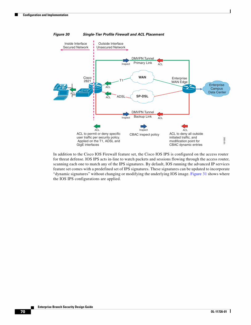
Configuration and Implementation
Figure 30 Single-Tier Profile Firewall and ACL Placement
In addition to the Cisco IOS Firewall feature set, the Cisco IOS IPS is configured on the access router for threat defense. IOS IPS acts in-line to watch packets and sessions flowing through the access router, scanning each one to match any of the IPS signatures. By default, IOS running the advanced IP services feature set comes with a predefined set of IPS signatures. These signatures can be updated to incorporate “dynamic signatures” without changing or modifying the underlying IOS image. Figure 31 shows where the IOS IPS configurations are applied.
1910
92
IP
DMVPN TunnelPrimary Link
WAN
SP-DSL
DMVPN TunnelBackup Link
EnterpriseWAN Edge
Enterprise Campus
Data Center
Cisco2821 T1
ADSL
Inside InterfaceSecured Network
Outside InterfaceUnsecured Network
Inspect
ACL
ACL
ACL
ACL
ACLInspect
ACLACL Inspect
ACL to permit or deny specificuser traffic per security policy. Applied on the T1, ADSL andGigE interfaces
CBAC inspect policy ACL to deny all outsideinitiated traffic, andmodification point forCBAC dynamic entries
70Enterprise Branch Security Design Guide
OL-11726-01
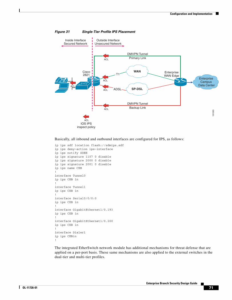
Configuration and Implementation
Figure 31 Single-Tier Profile IPS Placement
Basically, all inbound and outbound interfaces are configured for IPS, as follows:
ip ips sdf location flash://sdmips.sdfip ips deny-action ips-interfaceip ips notify SDEEip ips signature 1107 0 disableip ips signature 2000 0 disableip ips signature 2001 0 disableip ips name CEB!interface Tunnel0ip ips CEB in!interface Tunnel1ip ips CEB in!interface Serial0/0/0:0ip ips CEB in!interface GigabitEthernet1/0.193ip ips CEB in!interface GigabitEthernet1/0.200ip ips CEB in!interface Dialer1ip ips CEBin!
The integrated EtherSwitch network module has additional mechanisms for threat defense that are applied on a per-port basis. These same mechanisms are also applied to the external switches in the dual-tier and multi-tier profiles.
1910
93
IP
DMVPN TunnelPrimary Link
WAN
SP-DSL
DMVPN TunnelBackup Link
EnterpriseWAN Edge
Enterprise Campus
Data Center
Cisco2821 T1
ADSL
Inside InterfaceSecured Network
Outside InterfaceUnsecured Network
ACL
ACL
ACL
ACL
ACL
ACL
IOS IPSinspect policy
71Enterprise Branch Security Design Guide
OL-11726-01
Configuration and Implementation
Threat Defense for Catalyst Switches
Port Security
Port Security limits the number of MAC addresses that are able to connect to a switch and ensures that only approved MAC addresses are able to access the switch. This feature prevents MAC address flooding and ensures that only approved users can log onto the network. Port Security locks down a port when the number of MAC address entries on a port exceeds the number defined on the switch port, and an SNMP trap is sent to a syslog or centralized management server. Cisco recommends that only two MAC addresses be allowed on the port for port security: one for a phone, and one for a PC that connects to the phone. Other MAC addresses attempting to access a switch after the two have been fulfilled are not allowed access and dropped. Setting the trunk port for a maximum of 100 MAC addresses is recommended so that the trunk port does not drop any valid users. In addition, on each port, the port security violation mode is set to restrict any MAC addresses that exceed the limit, and any MAC address that is inactive is aged out. The following shows the Port Security configurations used:
interface FastEthernet1/0/2! description trunk port switchport trunk encapsulation dot1q switchport mode trunk switchport port-security maximum 100 switchport port-security!interface FastEthernet1/0/3! description phone with pc connected to phone switchport access vlan 193 switchport mode access switchport voice vlan 200 switchport port-security maximum 2 switchport port-security switchport port-security aging time 2 switchport port-security violation restrict switchport port-security aging type inactivity!interface FastEthernet1/0/22 ! description just PC only switchport access vlan 193 switchport mode access switchport port-security switchport port-security aging time 2 switchport port-security violation restrict switchport port-security aging type inactivity
DHCP Snooping
With the DHCP Snooping feature enabled, a switch port forwards DHCP requests only from trusted access ports and drops all other types of DHCP traffic. DHCP Snooping allows only designated DHCP ports or trusted uplink ports to relay DHCP messages by building a DHCP binding table containing a client IP address, MAC address, and port and VLAN number. DHCP Snooping eliminates rogue devices from behaving as the DHCP server. DHCP snooping acts like a firewall between untrusted hosts and DHCP servers. It also gives you a way to differentiate between untrusted interfaces connected to the end user and trusted interfaces connected to the DHCP server or another switch. The configurations for DHCP snooping are as follows:
ip dhcp smart-relay!ip dhcp snooping vlan 193,200ip dhcp snooping database flash:dhcp.txtip dhcp snooping database timeout 10ip dhcp snooping
72Enterprise Branch Security Design Guide
OL-11726-01
Configuration and Implementation
!interface FastEthernet1/0/2! description trunk port switchport trunk encapsulation dot1q switchport mode trunk switchport port-security maximum 100 switchport port-securityip dhcp snooping limit rate 100 ip dhcp snooping trust!interface FastEthernet1/0/3 ! description phone with pc connected to phone switchport access vlan 193 switchport mode access switchport voice vlan 200ip dhcp snooping limit rate 100
!interface FastEthernet1/0/22 ! description just PC only switchport access vlan 193 switchport mode accessip dhcp snooping limit rate 100
In addition to setting the VLANs to enable DHCP Snooping, the number of DHCP packets per second that an interface can receive is also limited. Cisco recommends an untrusted rate limit of not more than 100 packets per second. The rate limit applies to untrusted interfaces. In all profiles, all ports are assumed to be untrusted except the trunk ports connecting the access router to the switch.
Dynamic ARP Inspection
DAI maintains a binding table containing the IP and MAC address associations dynamically populated using DHCP Snooping. This feature ensures the integrity of user and default gateway information such that traffic cannot be captured. ARP spoofing or ARP poisoning attacks are mitigated through this feature. DAI is used to inspect all ARP request/response (gratuitious or non-gratuitious) coming from user-facing ports to ensure they belong to the ARP owner. The ARP owner is the port that has a DHCP binding that matches the IP address contained in the ARP relay. ARP packets from DAI trusted ports are not inspected and are bridged to their respective VLANs. DAI is supported on access ports and trunk ports. The configurations used for DAI are as follows:
ip arp inspection vlan 101-102,186ip arp inspection validate src-macip arp inspection log-buffer entries 100ip arp inspection log-buffer logs 20 interval 120
interface FastEthernet1/0/2! description trunk portswitchport trunk encapsulation dot1q switchport mode trunkip arp inspection trust ip arp inspection limit rate 5!interface FastEthernet1/0/3! description phone with pc connected to phone switchport access vlan 193 switchport mode access switchport voice vlan 200ip arp inspection limit rate 100!interface FastEthernet1/0/22! description just PC only switchport access vlan 193 switchport mode access
73Enterprise Branch Security Design Guide
OL-11726-01
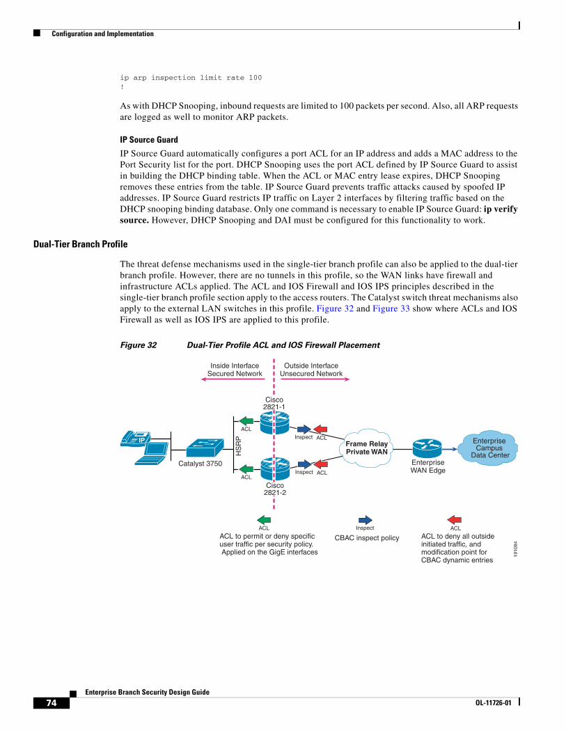
Configuration and Implementation
ip arp inspection limit rate 100!
As with DHCP Snooping, inbound requests are limited to 100 packets per second. Also, all ARP requests are logged as well to monitor ARP packets.
IP Source Guard
IP Source Guard automatically configures a port ACL for an IP address and adds a MAC address to the Port Security list for the port. DHCP Snooping uses the port ACL defined by IP Source Guard to assist in building the DHCP binding table. When the ACL or MAC entry lease expires, DHCP Snooping removes these entries from the table. IP Source Guard prevents traffic attacks caused by spoofed IP addresses. IP Source Guard restricts IP traffic on Layer 2 interfaces by filtering traffic based on the DHCP snooping binding database. Only one command is necessary to enable IP Source Guard: ip verify source. However, DHCP Snooping and DAI must be configured for this functionality to work.
Dual-Tier Branch Profile
The threat defense mechanisms used in the single-tier branch profile can also be applied to the dual-tier branch profile. However, there are no tunnels in this profile, so the WAN links have firewall and infrastructure ACLs applied. The ACL and IOS Firewall and IOS IPS principles described in the single-tier branch profile section apply to the access routers. The Catalyst switch threat mechanisms also apply to the external LAN switches in this profile. Figure 32 and Figure 33 show where ACLs and IOS Firewall as well as IOS IPS are applied to this profile.
Figure 32 Dual-Tier Profile ACL and IOS Firewall Placement
1910
94
Catalyst 3750
HS
RP Inspect
ACL
ACL
ACLACLInspect
ACLACL Inspect
ACL to permit or deny specificuser traffic per security policy. Applied on the GigE interfaces
CBAC inspect policy ACL to deny all outsideinitiated traffic, andmodification point forCBAC dynamic entries
IP Frame RelayPrivate WAN
EnterpriseWAN Edge
Enterprise Campus
Data Center
Inside InterfaceSecured Network
Outside InterfaceUnsecured Network
Cisco2821-1
Cisco2821-2
74Enterprise Branch Security Design Guide
OL-11726-01
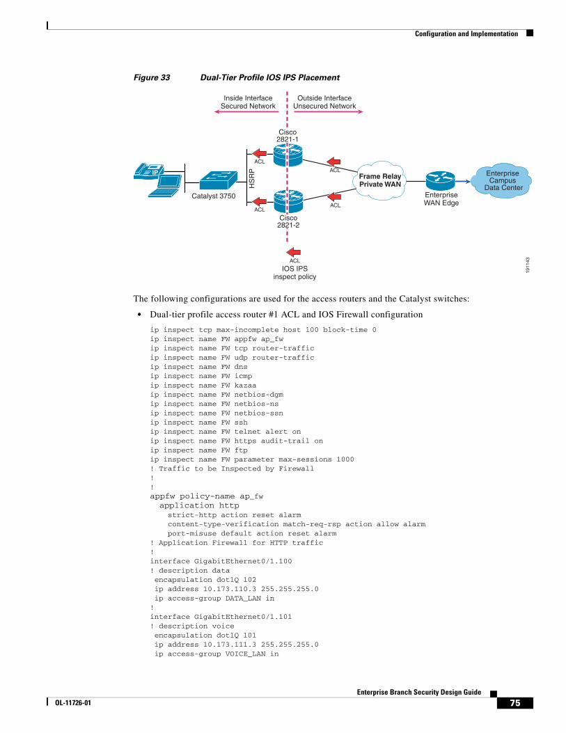
Configuration and Implementation
Figure 33 Dual-Tier Profile IOS IPS Placement
The following configurations are used for the access routers and the Catalyst switches:
• Dual-tier profile access router #1 ACL and IOS Firewall configuration
ip inspect tcp max-incomplete host 100 block-time 0ip inspect name FW appfw ap_fwip inspect name FW tcp router-trafficip inspect name FW udp router-trafficip inspect name FW dnsip inspect name FW icmpip inspect name FW kazaaip inspect name FW netbios-dgmip inspect name FW netbios-nsip inspect name FW netbios-ssnip inspect name FW sship inspect name FW telnet alert onip inspect name FW https audit-trail onip inspect name FW ftpip inspect name FW parameter max-sessions 1000! Traffic to be Inspected by Firewall!!appfw policy-name ap_fw application http strict-http action reset alarm content-type-verification match-req-rsp action allow alarm port-misuse default action reset alarm! Application Firewall for HTTP traffic!interface GigabitEthernet0/1.100! description data encapsulation dot1Q 102 ip address 10.173.110.3 255.255.255.0 ip access-group DATA_LAN in!interface GigabitEthernet0/1.101! description voice encapsulation dot1Q 101 ip address 10.173.111.3 255.255.255.0 ip access-group VOICE_LAN in
1911
43
Catalyst 3750
HS
RP
ACL
ACL
ACLACL
ACL
IOS IPSinspect policy
IP Frame RelayPrivate WAN
EnterpriseWAN Edge
Enterprise Campus
Data Center
Inside InterfaceSecured Network
Outside InterfaceUnsecured Network
Cisco2821-1
Cisco2821-2
75Enterprise Branch Security Design Guide
OL-11726-01

Configuration and Implementation
!interface Serial0/0/0.17 point-to-point ip address 10.173.199.2 255.255.255.252 ip access-group INET_WAN in ip inspect FW out!ip access-list extended DATA_LANpermit udp host 0.0.0.0 host 255.255.255.255 permit ip 10.173.110.0 0.0.0.255 any deny ip any any log!ip access-list extended INET_WANpermit eigrp any any! Allow Routing Updatespermit icmp any host 10.173.199.2 permit icmp any host 10.173.199.2 packet-too-big permit icmp any host 10.173.199.2 unreachable permit icmp any host 10.173.199.2 echo-reply permit icmp any host 10.173.199.2 time-exceeded! Allow Pings to Serial Interface for Troubleshootingpermit icmp any 10.173.110.0 0.0.0.255 permit icmp any 10.173.110.0 0.0.0.255 packet-too-big permit icmp any 10.173.110.0 0.0.0.255 unreachable permit icmp any 10.173.110.0 0.0.0.255 echo-reply permit icmp any 10.173.110.0 0.0.0.255 time-exceeded! Allow Pings to DATA network off LAN permit icmp any 10.173.111.0 0.0.0.255 permit icmp any 10.173.111.0 0.0.0.255 packet-too-big permit icmp any 10.173.111.0 0.0.0.255 unreachable permit icmp any 10.173.111.0 0.0.0.255 echo-reply permit icmp any 10.173.111.0 0.0.0.255 time-exceeded! Allow Pings to Voice network off LANpermit udp any host 10.173.199.2 eq ntp permit udp any host 10.173.199.2 eq 22 permit tcp any host 10.173.199.2 eq 22! Allow NTP and FTP to Serial Interface
deny ip host 255.255.255.255 any! Deny Directed Broadcastspermit ip any 10.173.110.0 0.0.0.255 permit ip any 10.173.111.0 0.0.0.255! Permit any IP traffic to LAN segmentdeny ip any any ! Deny All Else!ip access-list extended VOICE_LANpermit udp host 0.0.0.0 host 255.255.255.255 permit ip 10.173.111.0 0.0.0.255 any deny ip any any !
• Dual-tier profile access router #2 ACL and IOS Firewall configuration
ip inspect one-minute high 2000ip inspect tcp max-incomplete host 100 block-time 0ip inspect name FW appfw ap_fwip inspect name FW tcp router-trafficip inspect name FW udp router-trafficip inspect name FW dnsip inspect name FW icmpip inspect name FW kazaaip inspect name FW netbios-dgmip inspect name FW netbios-nsip inspect name FW netbios-ssn
76Enterprise Branch Security Design Guide
OL-11726-01

Configuration and Implementation
ip inspect name FW sship inspect name FW telnet alert onip inspect name FW https audit-trail onip inspect name FW ftpip inspect name FW parameter max-sessions 1000! Traffic to be Inspected by Firewall!appfw policy-name ap_fw application http strict-http action reset alarm content-type-verification match-req-rsp action allow alarm port-misuse default action reset alarm! Application Firewall for HTTP traffic!interface GigabitEthernet0/1.100! description data encapsulation dot1Q 102 ip address 10.173.110.2 255.255.255.0ip access-group DATA_LAN in!interface GigabitEthernet0/1.101! description voice encapsulation dot1Q 101 ip address 10.173.111.2 255.255.255.0ip access-group VOICE_LAN in!!interface Serial0/0/0.1 point-to-point ip address 10.173.199.6 255.255.255.252 ip access-group INET-WAN inip inspect FW out!ip access-list extended VOICE_LANpermit udp host 0.0.0.0 host 255.255.255.255 permit ip 10.173.111.0 0.0.0.255 any deny ip any anyip access-list extended INET_WAN permit eigrp any any! Allow only hosts from DATA networkpermit icmp any host 10.173.199.6 permit icmp any host 10.173.199.6 packet-too-big permit icmp any host 10.173.199.6 unreachable permit icmp any host 10.173.199.6 echo-reply permit icmp any host 10.173.199.6 time-exceeded! Allow Pings to Serial Interface for Troubleshootingpermit icmp any 10.173.110.0 0.0.0.255 permit icmp any 10.173.110.0 0.0.0.255 packet-too-big permit icmp any 10.173.110.0 0.0.0.255 unreachable permit icmp any 10.173.110.0 0.0.0.255 echo-reply permit icmp any 10.173.110.0 0.0.0.255 time-exceeded! Allow Pings to DATA network off LAN permit icmp any 10.173.111.0 0.0.0.255 permit icmp any 10.173.111.0 0.0.0.255 packet-too-big permit icmp any 10.173.111.0 0.0.0.255 unreachable permit icmp any 10.173.111.0 0.0.0.255 echo-reply permit icmp any 10.173.111.0 0.0.0.255 time-exceeded! Allow Pings to Voice network off LANpermit udp any host 10.173.199.6 eq ntp permit udp any host 10.173.199.6 eq 22 permit tcp any host 10.173.199.6 eq 22! Allow NTP and FTP to Serial Interfacedeny ip host 255.255.255.255 any! Deny Directed Broadcastspermit ip any 10.173.110.0 0.0.0.255
77Enterprise Branch Security Design Guide
OL-11726-01
Configuration and Implementation
permit ip any 10.173.111.0 0.0.0.255! Permit any IP traffic to LAN segmentdeny ip any any ! Deny All Elseip access-list extended DATA_LANpermit udp host 0.0.0.0 host 255.255.255.255 permit ip 10.173.110.0 0.0.0.255 any deny ip any any !
• Dual-tier profile access router #1 IOS IPS configuration
ip ips deny-action ips-interfaceip ips signature 1107 0 disableip ips signature 2000 0 disableip ips signature 2001 0 disableip ips name DSB!interface GigabitEthernet0/1.100! description data encapsulation dot1Q 102 ip address 10.173.110.3 255.255.255.0ip ips DSB in!interface Serial0/0/0.17 point-to-point ip address 10.173.199.2 255.255.255.252ip ips DSB in
• Dual-tier profile access router #2 IOS IPS configuration
ip ips deny-action ips-interfaceip ips signature 1107 0 disableip ips signature 2000 0 disableip ips signature 2001 0 disableip ips name DSB!interface GigabitEthernet0/1.100! description data encapsulation dot1Q 102 ip address 10.173.110.2 255.255.255.0ip ips DSB in!interface Serial0/0/0.1 point-to-point ip address 10.173.199.6 255.255.255.252ip ips DSB in
• Dual-tier profile Catalyst switch threat defense configuration
ip dhcp smart-relay!ip dhcp snooping vlan 101-102ip dhcp snooping database flash:dhcp.txtip dhcp snooping database timeout 10ip dhcp snoopingip arp inspection vlan 101-102ip arp inspection validate src-macip arp inspection log-buffer entries 100ip arp inspection log-buffer logs 20 interval 120!interface GigabitEthernet1/0/1! description trunk port switchport trunk encapsulation dot1q switchport mode trunk switchport port-security aging time 10 ip arp inspection trust
78Enterprise Branch Security Design Guide
OL-11726-01
Configuration and Implementation
load-interval 30ip dhcp snooping limit rate 10 ip dhcp snooping trust!interface GigabitEthernet1/0/6! description phone with PC connected to phone switchport access vlan 102 switchport mode access switchport voice vlan 101 switchport port-security maximum 2 switchport port-security switchport port-security aging time 2 switchport port-security violation restrict switchport port-security aging type inactivity ip arp inspection limit rate 100 load-interval 30spanning-tree portfast spanning-tree bpduguard enable ip verify source ip dhcp snooping limit rate 100!interface GigabitEthernet1/0/27! description data only ports switchport access vlan 102 switchport mode access switchport port-security switchport port-security aging time 2 switchport port-security violation restrict switchport port-security aging type inactivity ip arp inspection limit rate 100 load-interval 30spanning-tree portfast spanning-tree bpduguard enable ip verify source ip dhcp snooping limit rate 100!
The only difference between the single-tier and dual-tier branch profiles are the number of physical devices where these mechanisms must be applied.
Multi-Tier Profile
The multi-tier branch profile uses a combination of infrastructure ACLs, firewalls, and IPS to provide threat defense to this network. The access routers connecting to the MPLS cloud provide a WAN termination barrier from the internal branch network behind the ASA firewalls. As such, infrastructure ACLs should be placed inbound on the FastEthernet links to allow pings for troubleshooting purposes and networks destined to the internal branch behind the ASA. All other traffic, including networks mimicing the branch network, should be denied. Figure 34 shows the WAN termination devices and the infrastructure ACLs placed.
79Enterprise Branch Security Design Guide
OL-11726-01
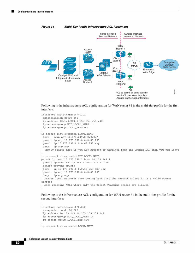
Configuration and Implementation
Figure 34 Multi-Tier Profile Infrastructure ACL Placement
Following is the infrastructure ACL configuration for WAN router #1 in the multi-tier profile for the first interface:
interface FastEthernet0/0.201 encapsulation dot1Q 201 ip address 10.173.249.1 255.255.255.248 ip access-group NOT_LOCAL_NETS in ip access-group LOCAL_NETS out!ip access-list extended LOCAL_NETS deny icmp any 10.173.249.8 0.0.0.7 permit ip any 10.173.192.0 0.0.63.255 permit ip 10.173.192.0 0.0.63.255 any deny ip any any! Simply states that if you are sourced or destined from the Branch LAN then you can leave!ip access-list extended NOT_LOCAL_NETSpermit ip host 10.173.249.2 host 10.173.249.1 permit ip host 10.173.249.2 host 224.0.0.10 remark prevent smurfs deny ip 10.173.192.0 0.0.63.255 any log permit ip any 10.173.192.0 0.0.63.255 deny ip any any ! Denies local networks from coming back into the network unless it is a valid source address! Anti-spoofing ACLs where only the Object Tracking probes are allowed!
Following is the infrastructure ACL configuration for WAN router #1 in the multi-tier profile for the second interface:
!interface FastEthernet0/0.202 encapsulation dot1Q 202 ip address 10.173.249.10 255.255.255.248 ip access-group NOT_LOCAL_NETS in ip access-group LOCAL_NETS out!ip access-list extended LOCAL_NETS
1911
44
Catalyst 3750 andIntegrated Etherswitch
Stack
IP SPMPLS
EnterpriseWAN Edge
Enterprise Campus
Data Center
Access Router 1
Access Router 2
Stateful ASA Failover
Cisco2821-1
Cisco2821-2
Inside InterfaceSecured Network
Outside InterfaceUnsecured Network
WAN Router 1
WAN Router 2
ACL
ACL
ACL
ACL to permit or deny specificuser traffic per security policy. Applied on the GigE interfaces
80Enterprise Branch Security Design Guide
OL-11726-01
Configuration and Implementation
deny icmp any 10.173.249.8 0.0.0.7 permit ip any 10.173.192.0 0.0.63.255 permit ip 10.173.192.0 0.0.63.255 any deny ip any any! Simply states that if you are sourced or destined from the Branch LAN then you can leave
!ip access-list extended NOT_LOCAL_NETSpermit eigrp any any permit ip 10.173.249.8 0.0.0.7 10.173.249.8 0.0.0.7 remark prevent smurfs deny ip 10.173.192.0 0.0.63.255 any log permit ip any 10.173.192.0 0.0.0.63 permit icmp 10.59.136.0 0.0.0.255 any permit ip 10.59.136.0 0.0.0.255 any! Denies local networks from coming back into the network unless it is a valid source address! Anti-spoofing ACLs where only the Object Tracking probes are allowed
The ASA security appliance is an external firewall device for this network. The single-tier and dual-tier profiles use the integrated IOS Firewall feature set within the access routers. The ASA security appliance is a dedicated, standalone device for advanced firewall, VPN, and IPS functionality. In this profile, the ASA provides a barrier between the internal branch network consisting of the service routers and switches and the WAN termination access routers. A dedicated firewall removes the CPU burden for this function from the router while providing the same functionality. The ASA as a firewall protects inside networks from unauthorized access by users on an outside network. All traffic that goes through the ASA is inspected using the adaptive security algorithm and is either dropped or allowed through.
Unlike the Cisco IOS Firewall feature set, the ASA has security levels that define an interface. The higher a security level, the more secure the network. By default, the ASA allows traffic to flow freely from an inside network that has a higher security level to an outside network that has a lower security. In this profile, the outside network connected to the WAN termination access routers have a security level of 25. The inside network has a security level of 75.
Traffic flowing across an interface in the ASA can be controlled in two ways. Traffic that enters the ASA can be controlled by attaching an inbound ACL to the source interface. Traffic that exits the ASA can be controlled by attaching an outbound ACL to the destination interface. By default, traffic can exit the ASA on any interface unless it is restricted by an outbound ACL. In this profile, two inbound ACLs have been defined. The inbound ACL applied to the LAN interface allows all internal LAN traffic to communicate with each other. The inbound ACL applied to the WAN interface allows all pings and all traffic destined to the internal branch network to pass.
When a user establishes a connection, the security appliance checks the packet against access lists, and creates an entry for the session in the fast path, so that further packets can bypass time-consuming checks. However, the fast path relies on predictable port numbers. Many protocols open secondary TCP or UDP ports. The initial session on a well-known port is used to negotiate dynamically assigned port numbers. Other applications embed an IP address in the packet that needs to match the source address when it goes through the security appliance. If applications such as these are used, application inspection is required on the ASA.
When application inspection for a service that embeds IP addresses is enabled, the security appliance translates embedded addresses and updates any checksum or other fields that are affected by the translation. When application inspection for a service that uses dynamically assigned ports is enabled, the security appliance monitors sessions to identify the dynamic port assignments, and permits data exchange on these ports for the duration of the specific session. By default, the configuration includes a policy that matches all default application inspection traffic and applies inspection to the traffic on all interfaces (a global policy). Default application inspection traffic includes traffic to the default ports for each protocol. You can only apply one global policy.
81Enterprise Branch Security Design Guide
OL-11726-01
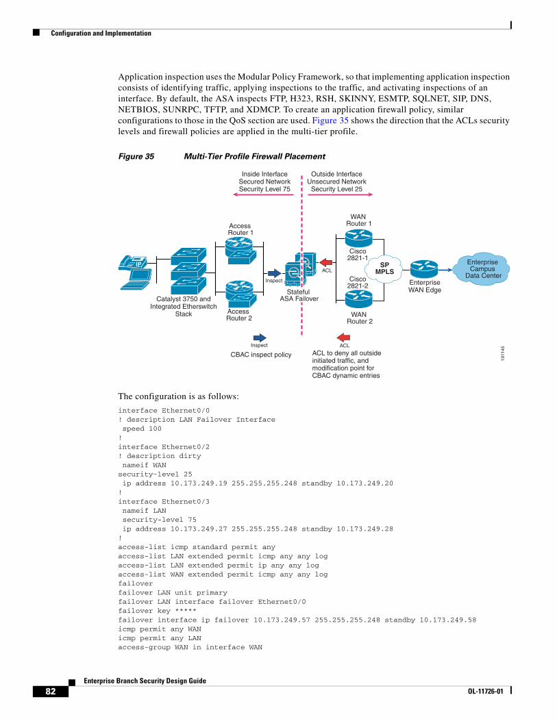
Configuration and Implementation
Application inspection uses the Modular Policy Framework, so that implementing application inspection consists of identifying traffic, applying inspections to the traffic, and activating inspections of an interface. By default, the ASA inspects FTP, H323, RSH, SKINNY, ESMTP, SQLNET, SIP, DNS, NETBIOS, SUNRPC, TFTP, and XDMCP. To create an application firewall policy, similar configurations to those in the QoS section are used. Figure 35 shows the direction that the ACLs security levels and firewall policies are applied in the multi-tier profile.
Figure 35 Multi-Tier Profile Firewall Placement
The configuration is as follows:
interface Ethernet0/0! description LAN Failover Interface speed 100!interface Ethernet0/2! description dirty nameif WANsecurity-level 25 ip address 10.173.249.19 255.255.255.248 standby 10.173.249.20!interface Ethernet0/3 nameif LAN security-level 75 ip address 10.173.249.27 255.255.255.248 standby 10.173.249.28!access-list icmp standard permit anyaccess-list LAN extended permit icmp any any logaccess-list LAN extended permit ip any any logaccess-list WAN extended permit icmp any any logfailoverfailover LAN unit primaryfailover LAN interface failover Ethernet0/0failover key *****failover interface ip failover 10.173.249.57 255.255.255.248 standby 10.173.249.58icmp permit any WANicmp permit any LANaccess-group WAN in interface WAN
1911
45
Catalyst 3750 andIntegrated Etherswitch
Stack
IP SPMPLS
EnterpriseWAN Edge
Enterprise Campus
Data Center
Access Router 1
Access Router 2
Cisco2821-1
Cisco2821-2
Inside InterfaceSecured NetworkSecurity Level 75
Outside InterfaceUnsecured Network
Security Level 25
WAN Router 1
WAN Router 2
Inspect
ACL
ACLInspect
CBAC inspect policy ACL to deny all outsideinitiated traffic, andmodification point forCBAC dynamic entries
Stateful ASA Failover
82Enterprise Branch Security Design Guide
OL-11726-01
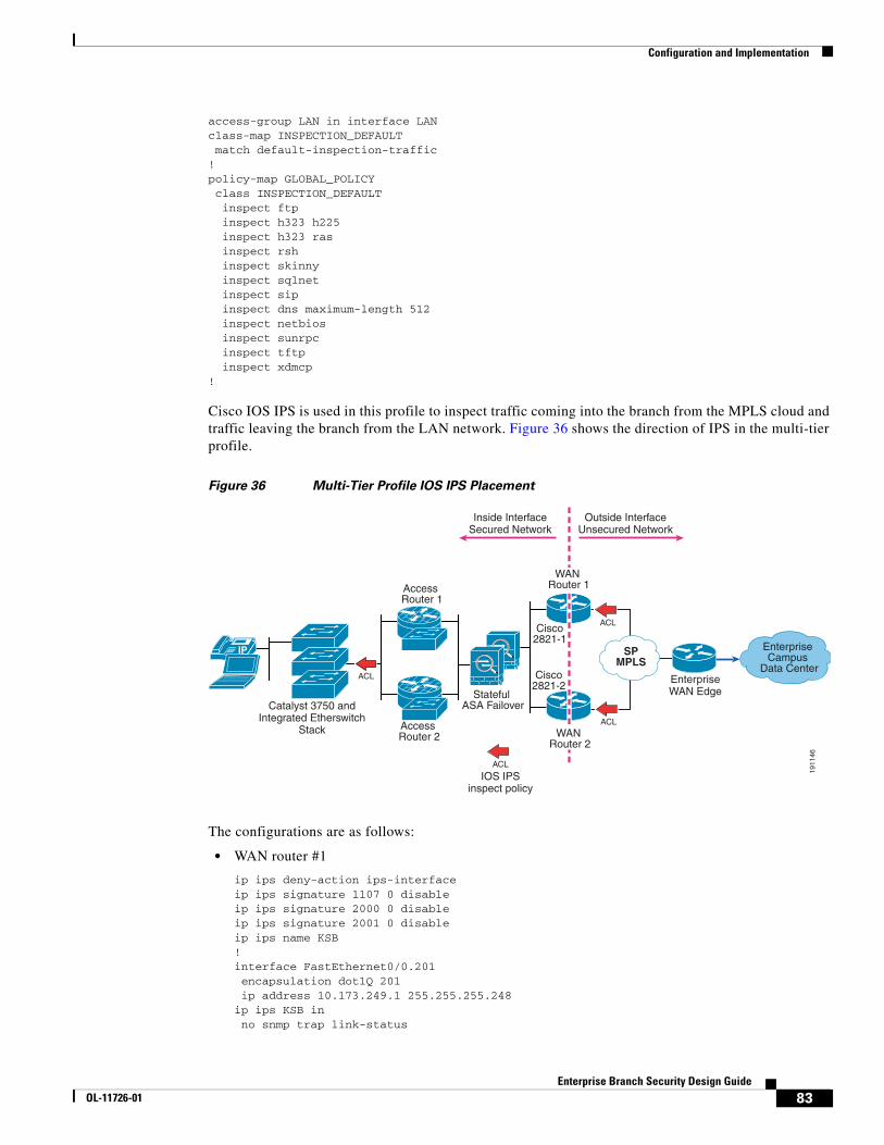
Configuration and Implementation
access-group LAN in interface LANclass-map INSPECTION_DEFAULT match default-inspection-traffic!policy-map GLOBAL_POLICY class INSPECTION_DEFAULT inspect ftp inspect h323 h225 inspect h323 ras inspect rsh inspect skinny inspect sqlnet inspect sip inspect dns maximum-length 512 inspect netbios inspect sunrpc inspect tftp inspect xdmcp!
Cisco IOS IPS is used in this profile to inspect traffic coming into the branch from the MPLS cloud and traffic leaving the branch from the LAN network. Figure 36 shows the direction of IPS in the multi-tier profile.
Figure 36 Multi-Tier Profile IOS IPS Placement
The configurations are as follows:
• WAN router #1
ip ips deny-action ips-interfaceip ips signature 1107 0 disableip ips signature 2000 0 disableip ips signature 2001 0 disableip ips name KSB!interface FastEthernet0/0.201 encapsulation dot1Q 201 ip address 10.173.249.1 255.255.255.248ip ips KSB in no snmp trap link-status
1911
46
Catalyst 3750 andIntegrated Etherswitch
Stack
IP SPMPLS
EnterpriseWAN Edge
Enterprise Campus
Data Center
Access Router 1
Access Router 2
Stateful ASA Failover
Cisco2821-1
Cisco2821-2
Inside InterfaceSecured Network
Outside InterfaceUnsecured Network
WAN Router 1
WAN Router 2
ACL
ACL
ACL
ACL
IOS IPSinspect policy
83Enterprise Branch Security Design Guide
OL-11726-01
Summary
!
• WAN router #2
ip ips deny-action ips-interfaceip ips signature 1107 0 disableip ips signature 2000 0 disableip ips signature 2001 0 disableip ips name KSB!interface FastEthernet0/0.202 encapsulation dot1Q 202 ip address 10.173.249.10 255.255.255.2ip ips KSB in no snmp trap link-status!
• Access router #1
ip ips deny-action ips-interfaceip ips signature 1107 0 disableip ips signature 2000 0 disableip ips signature 2001 0 disableip ips name KSB!interface GigabitEthernet1/0 ip address 10.173.249.41 255.255.255.248 ip ips KSB in!
• Access router #2
ip ips deny-action ips-interfaceip ips signature 1107 0 disableip ips signature 2000 0 disableip ips signature 2001 0 disableip ips name KSB!interface GigabitEthernet1/0 ip address 10.173.249.33 255.255.255.248 ip ips KSB in!
SummaryThe design recommendations in this design chapter are best practices designed to achieve a highly available secure branch based on three profiles. This design chapter sets the foundation of the Enterprise Branch Architecture by establishing three profiles and overlaying WAN, LAN, network fundamentals, and security services. Configurations are given for each profile established. The configurations and architectures established in this chapter are used as a baseline now to overlay the other services established in the integrated services building block layer and the application networking services layer.
Enterprise branch networks can take advantage of the design principles and implementation best practices described in this design chapter to implement a network that provides the optimal flexibility as the business requirements of the branch network infrastructure evolve.
84Enterprise Branch Security Design Guide
OL-11726-01
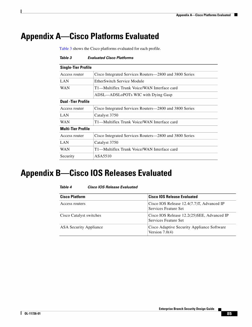
Appendix A—Cisco Platforms Evaluated
Appendix A—Cisco Platforms EvaluatedTable 3 shows the Cisco platforms evaluated for each profile.
Appendix B—Cisco IOS Releases Evaluated
Table 3 Evaluated Cisco Platforms
Single-Tier Profile
Access router Cisco Integrated Services Routers—2800 and 3800 Series
LAN EtherSwitch Service Module
WAN T1—Multiflex Trunk Voice/WAN Interface card
ADSL—ADSLoPOTs WIC with Dying Gasp
Dual -Tier Profile
Access router Cisco Integrated Services Routers—2800 and 3800 Series
LAN Catalyst 3750
WAN T1—Multiflex Trunk Voice/WAN Interface card
Multi-Tier Profile
Access router Cisco Integrated Services Routers—2800 and 3800 Series
LAN Catalyst 3750
WAN T1—Multiflex Trunk Voice/WAN Interface card
Security ASA5510
Table 4 Cisco IOS Release Evaluated
Cisco Platform Cisco IOS Release Evaluated
Access routers Cisco IOS Release 12.4(7.7)T, Advanced IP Services Feature Set
Cisco Catalyst switches Cisco IOS Release 12.2(25)SEE, Advanced IP Services Feature Set
ASA Security Appliance Cisco Adaptive Security Appliance Software Version 7.0(4)
85Enterprise Branch Security Design Guide
OL-11726-01
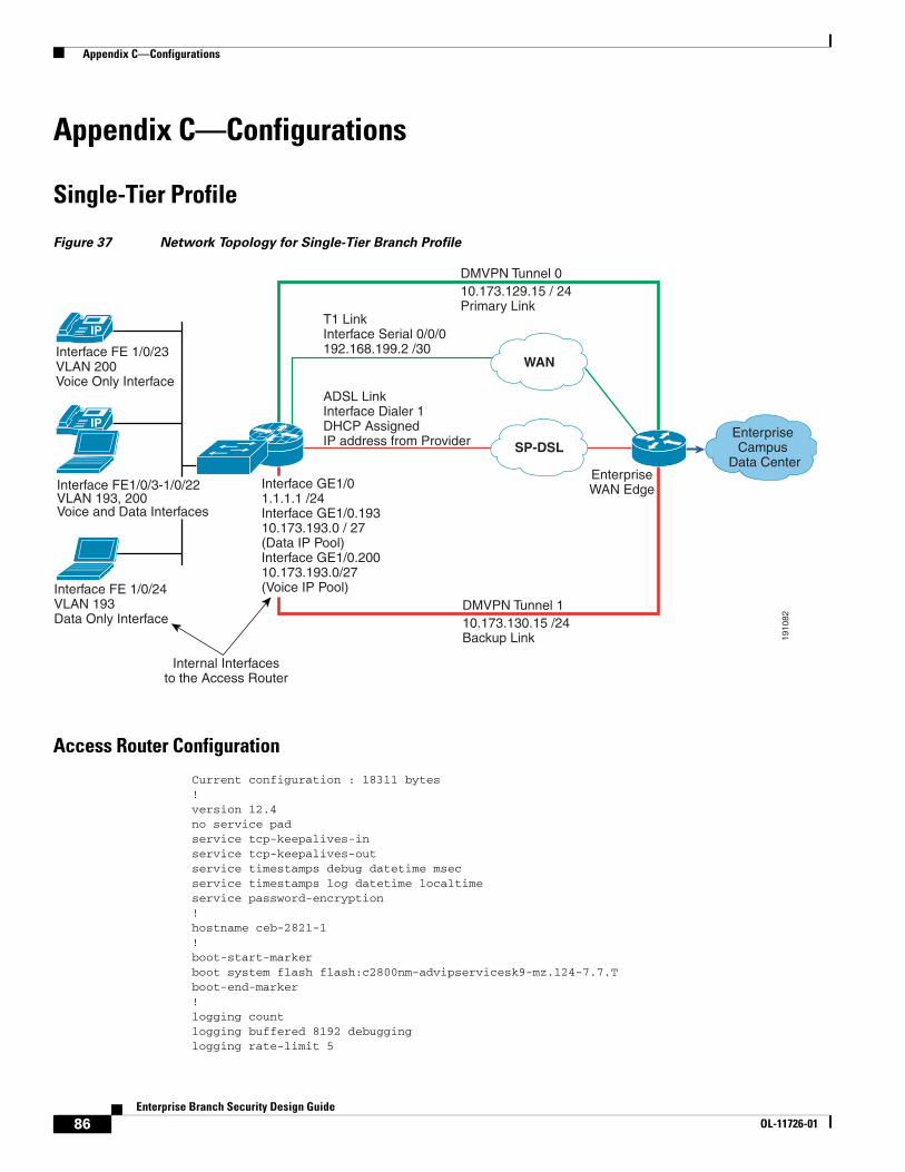
Appendix C—Configurations
Appendix C—Configurations
Single-Tier Profile
Figure 37 Network Topology for Single-Tier Branch Profile
Access Router Configuration
Current configuration : 18311 bytes!version 12.4no service padservice tcp-keepalives-inservice tcp-keepalives-outservice timestamps debug datetime msecservice timestamps log datetime localtimeservice password-encryption!hostname ceb-2821-1!boot-start-markerboot system flash flash:c2800nm-advipservicesk9-mz.124-7.7.Tboot-end-marker!logging countlogging buffered 8192 debugginglogging rate-limit 5
1910
82
Interface FE 1/0/23VLAN 200Voice Only Interface
Interface FE 1/0/24VLAN 193Data Only Interface
Interface FE1/0/3-1/0/22VLAN 193, 200Voice and Data Interfaces
IP
WAN
SP-DSL
EnterpriseWAN Edge
Enterprise Campus
Data Center
IP
Internal Interfacesto the Access Router
Interface GE1/01.1.1.1 /24Interface GE1/0.19310.173.193.0 / 27(Data IP Pool)Interface GE1/0.20010.173.193.0/27(Voice IP Pool)
T1 LinkInterface Serial 0/0/0192.168.199.2 /30
ADSL LinkInterface Dialer 1DHCP Assigned IP address from Provider
DMVPN Tunnel 110.173.130.15 /24Backup Link
DMVPN Tunnel 010.173.129.15 / 24Primary Link
86Enterprise Branch Security Design Guide
OL-11726-01

Appendix C—Configurations
no logging consoleenable secret 5 $1$1ZoH$eUqctzD0NrObry5sgk/jz0!aaa new-model!aaa authentication login ssh_users group tacacs+aaa accounting send stop-record authentication failureaaa accounting exec ssh_users start-stop group tacacs+aaa accounting commands 7 ssh_users start-stop group tacacs+!aaa session-id common!resource policy!clock timezone est -5network-clock-participate wic 0no ip source-route!ip nbar port-map custom-03 tcp 5554 9996ip nbar port-map custom-02 udp 1434ip nbar port-map custom-01 tcp 3200 3201 3202 3203 3600ip nbar port-map netbios udp 135 137 138 139 445ip nbar port-map netbios tcp 137 139 445ip cefip dhcp relay information trust-allno ip dhcp use vrf connected!ip dhcp pool data_lan network 10.173.193.0 255.255.255.128 dns-server 10.59.138.4 default-router 10.173.193.1!ip dhcp pool voice_lan network 10.173.1.128 255.255.255.128 dns-server 10.59.138.51 default-router 10.173.1.129 option 150 ip 10.59.138.51 domain-name cisco.com!no ip bootp serverno ip domain lookupip domain name ese.cisco.comip multicast-routingip ssh time-out 60ip ssh authentication-retries 2ip ssh source-interface GigabitEthernet0/0.186ip inspect one-minute high 2000ip inspect tcp max-incomplete host 100 block-time 0ip inspect name FW appfw APPFWip inspect name FW tcp router-trafficip inspect name FW udp router-trafficip inspect name FW dnsip inspect name FW icmpip inspect name FW kazaaip inspect name FW netbios-dgmip inspect name FW netbios-nsip inspect name FW netbios-ssnip inspect name FW sship inspect name FW telnet alert onip inspect name FW httpsip inspect name FW ftpip inspect name FW parameter max-sessions 1000ip ips sdf location flash://sdmips.sdfip ips deny-action ips-interface
87Enterprise Branch Security Design Guide
OL-11726-01

Appendix C—Configurations
ip ips notify SDEEip ips signature 1107 0 disableip ips signature 2000 0 disableip ips signature 2001 0 disableip ips name CEBlogin block-for 30 attempts 3 within 200login delay 2vpdn enable!appfw policy-name APPFW application http port-misuse default action allow alarm request-method rfc default action allow alarm timeout 60 application im yahoo service default action allow alarm application im msn server deny name msn.cisco.com timeout 60 alert on application im aol service text-chat action allow alarm!voice-card 0 no dspfarm!crypto pki trustpoint TP-self-signed-3550329425 enrollment selfsigned subject-name cn=IOS-Self-Signed-Certificate-3550329425 revocation-check none rsakeypair TP-self-signed-3550329425!!crypto pki certificate chain TP-self-signed-3550329425 certificate self-signed 01 quitusername cisco password 7 121A0C041104!!controller T1 0/0/0 framing esf clock source internal linecode b8zs cablelength short 133 channel-group 0 timeslots 1-24!class-map match-all BRANCH-BULK-DATA match access-group name BULK-DATA-APPSclass-map match-all SQL-SLAMMER match protocol custom-02 match packet length min 404 max 404class-map match-all BULK-DATA match ip dscp af11 af12class-map match-all INTERACTIVE-VIDEO match ip dscp af41 af42class-map match-any CALL-SIGNALLING match ip dscp cs3 match ip dscp af31class-map match-any BRANCH-SCAVENGER match protocol napster match protocol gnutella match protocol fasttrack match protocol kazaa2class-map match-all NET-MGMG
88Enterprise Branch Security Design Guide
OL-11726-01

Appendix C—Configurations
match ip dscp cs2class-map match-all TRANSACTIONAL-DATA match ip dscp af21 af22class-map match-any BRANCH-TRANSACTIONAL-DATA match protocol citrix match protocol ldap match protocol sqlnet match protocol http url "*cisco.com" match protocol custom-01class-map match-all BRANCH-MISSION-CRITICAL match access-group name MISSION-CRITICAL-SERVERSclass-map match-any WORMS match protocol http url "*.ida*" match protocol http url "*cmd.exe*" match protocol http url "*root.exe*" match protocol http url "*readme.eml*" match class-map SQL-SLAMMER match protocol exchange match protocol netbios match protocol custom-03class-map match-all VOICE match ip dscp efclass-map match-all MISSION-CRITICAL-DATA match ip dscp 25class-map match-any BRANCH-NET-MGMT match protocol snmp match protocol syslog match protocol telnet match protocol nfs match protocol dns match protocol icmp match protocol tftpclass-map match-all ROUTING match ip dscp cs6class-map match-all SCAVENGER match ip dscp cs1!policy-map BRANCH-LAN-EDGE-OUT class CLASS-DEFAULT set cos dscppolicy-map BRANCH-LAN-EDGE-IN class BRANCH-MISSION-CRITICAL set ip dscp 25 class BRANCH-TRANSACTIONAL-DATA set ip dscp af21 class BRANCH-NET-MGMT set ip dscp cs2 class BRANCH-BULK-DATA set ip dscp af11 class BRANCH-SCAVENGER set ip dscp cs1 class WORMS drop class CLASS-DEFAULT set ip dscp defaultpolicy-map BRANCH-WAN-EDGE class VOICE priority percent 18 class INTERACTIVE-VIDEO priority percent 15 class CALL-SIGNALLING bandwidth percent 5 class ROUTING bandwidth percent 3
89Enterprise Branch Security Design Guide
OL-11726-01

Appendix C—Configurations
class NET-MGMG bandwidth percent 2 class MISSION-CRITICAL-DATA bandwidth percent 15 class TRANSACTIONAL-DATA bandwidth percent 12 random-detect dscp-based class BULK-DATA bandwidth percent 4 random-detect dscp-based class SCAVENGER bandwidth percent 1 class CLASS-DEFAULT bandwidth percent 25 random-detect!crypto isakmp policy 1 encr 3des authentication pre-sharecrypto isakmp key secret address 0.0.0.0 0.0.0.0crypto isakmp keepalive 10!crypto ipsec transform-set BRB esp-3des esp-sha-hmaccrypto ipsec transform-set BRB-BACK esp-3des esp-sha-hmac!crypto ipsec profile DMVPN set transform-set BRB!crypto ipsec profile DMVPN-BACK set transform-set BRB-BACK!interface Tunnel0 ip address 10.173.129.15 255.255.255.0 ip access-group INET in no ip redirects no ip unreachables no ip proxy-arp ip mtu 1400 ip pim nbma-mode ip pim sparse-mode ip nhrp authentication secret ip nhrp map multicast dynamic ip nhrp map multicast 192.168.201.1 ip nhrp map 10.173.129.1 192.168.201.1 ip nhrp network-id 10203 ip nhrp nhs 10.173.129.1 ip inspect FW out ip ips CEB in ip virtual-reassembly ip route-cache flow load-interval 30 delay 500 no clns route-cache tunnel source Serial0/0/0:0 tunnel mode gre multipoint tunnel key 123 tunnel protection ipsec profile DMVPN!interface Tunnel1 ip address 10.173.130.15 255.255.255.0 ip access-group INET-BACK in no ip redirects no ip unreachables no ip proxy-arp
90Enterprise Branch Security Design Guide
OL-11726-01

Appendix C—Configurations
ip mtu 1400 ip pim nbma-mode ip pim sparse-mode ip nhrp authentication secret ip nhrp map multicast dynamic ip nhrp map 10.173.130.1 192.168.206.1 ip nhrp map multicast 192.168.206.1 ip nhrp network-id 30201 ip nhrp nhs 10.173.130.1 ip inspect FW out ip ips CEB in ip virtual-reassembly ip route-cache flow load-interval 30 delay 2000 no clns route-cache tunnel source Dialer1 tunnel mode gre multipoint tunnel key 321 tunnel protection ipsec profile DMVPN-BACK!interface Loopback0 ip address 10.173.1.1 255.255.255.128 no ip redirects no ip unreachables no ip proxy-arp ip virtual-reassembly ip route-cache flow!interface Serial0/0/0:0 ip address 192.168.199.2 255.255.255.248 ip access-group WAN-LINK in no ip redirects no ip unreachables no ip proxy-arp ip nbar protocol-discovery ip ips CEB in ip virtual-reassembly ip route-cache flow max-reserved-bandwidth 100 service-policy output BRANCH-WAN-EDGE!interface ATM0/1/0 no ip address no ip redirects no ip unreachables no ip proxy-arp load-interval 30 no atm ilmi-keepalive dsl operating-mode auto!interface ATM0/1/0.35 point-to-point bandwidth 768 no snmp trap link-status pvc dsl 0/35 vbr-nrt 768 768 tx-ring-limit 3 pppoe max-sessions 5 service-policy output BRANCH-WAN-EDGE max-reserved-bandwidth 100 pppoe-client dial-pool-number 1!interface GigabitEthernet1/0 description internal interface to session into switch
91Enterprise Branch Security Design Guide
OL-11726-01

Appendix C—Configurations
ip address 1.1.1.1 255.255.255.0 no ip redirects no ip unreachables no ip proxy-arp ip route-cache flow power inline never!interface GigabitEthernet1/0.193 description data vlan for data only devices encapsulation dot1Q 193 ip address 10.173.193.1 255.255.255.128 ip access-group LANOUT in no ip redirects no ip unreachables no ip proxy-arp ip ips CEB in ip virtual-reassembly ip policy route-map NO_SPLIT no snmp trap link-status service-policy input BRANCH-LAN-EDGE-IN service-policy output BRANCH-LAN-EDGE-OUT!interface GigabitEthernet1/0.200 description voice vlan for voice only devices encapsulation dot1Q 200 ip address 10.173.1.129 255.255.255.128 ip access-group VOICEOUT in no ip redirects no ip unreachables no ip proxy-arp ip ips CEB in ip virtual-reassembly ip policy route-map NO_SPLIT no snmp trap link-status service-policy output BRANCH-LAN-EDGE-OUT!interface Dialer1 bandwidth 768 ip address negotiated ip access-group DIALER-LINK in no ip redirects no ip unreachables no ip proxy-arp ip mtu 1400 ip nbar protocol-discovery ip ips CEB in ip virtual-reassembly encapsulation ppp ip route-cache flow load-interval 30 dialer pool 1 dialer-group 1 no cdp enable ppp authentication chap callin ppp chap hostname [email protected] ppp chap password 7 1316181A0458 ppp ipcp dns request ppp ipcp wins request max-reserved-bandwidth 100 service-policy output BRANCH-WAN-EDGE!router eigrp 10 passive-interface GigabitEthernet1/0.193 passive-interface GigabitEthernet1/0.200
92Enterprise Branch Security Design Guide
OL-11726-01

Appendix C—Configurations
network 10.0.0.0 no auto-summary!ip route 0.0.0.0 0.0.0.0 Serial0/0/0:0ip route 0.0.0.0 0.0.0.0 Dialer1 200ip route 192.168.201.1 255.255.255.255 Serial0/0/0:0ip route 192.168.206.1 255.255.255.255 Dialer1 200!no ip http serverip http secure-serverip tacacs source-interface Loopback0!ip access-list extended LANOUT permit udp host 0.0.0.0 host 255.255.255.255 permit ip 10.173.193.0 0.0.0.127 any deny ip any any ip access-list extended VOICEOUT permit udp host 0.0.0.0 host 255.255.255.255 permit ip 10.173.1.128 0.0.0.127 any deny ip any anyip access-list extended WAN-LINK permit esp any any permit gre any any permit udp any host 192.168.199.2 eq isakmp permit udp any any eq non500-isakmp permit icmp any host 192.168.199.2 permit icmp any host 192.168.199.2 packet-too-big permit icmp any host 192.168.199.2 unreachable permit icmp any any echo-reply permit icmp any any time-exceeded remark ssh permit tcp any eq 22 any remark NTP ACL permit udp any eq ntp any eq ntp deny tcp any any deny udp any any deny ip host 255.255.255.255 any deny ip any anyip access-list extended DIALER-LINK permit esp any any permit gre any any permit udp any host 10.173.129.1 eq isakmp permit udp any any eq non500-isakmp permit icmp any host 10.173.129.1 permit icmp any host 10.173.129.1 packet-too-big permit icmp any host 10.173.129.1 unreachable permit icmp any any echo-reply permit icmp any any time-exceeded remark ssh permit tcp any eq 22 any remark NTP ACL permit udp any eq ntp any eq ntp deny tcp any any deny udp any any deny ip host 255.255.255.255 any deny ip any anyip access-list extended BULK-DATA-APPS permit tcp any any eq ftp permit tcp any any eq ftp-data permit tcp any any eq pop3 permit tcp any any eq 143ip access-list extended INET permit eigrp any any permit icmp any 10.173.129.0 0.0.0.255
93Enterprise Branch Security Design Guide
OL-11726-01

Appendix C—Configurations
permit icmp any 10.173.129.0 0.0.0.255 packet-too-big permit icmp any 10.173.129.0 0.0.0.255 unreachable permit icmp any 10.173.129.0 0.0.0.255 echo-reply permit icmp any 10.173.129.0 0.0.0.255 time-exceeded permit icmp any 10.173.193.0 0.0.0.255 permit icmp any 10.173.193.0 0.0.0.255 packet-too-big permit icmp any 10.173.193.0 0.0.0.255 unreachable permit icmp any 10.173.193.0 0.0.0.255 echo-reply permit icmp any 10.173.193.0 0.0.0.255 time-exceeded permit icmp any 10.173.1.128 0.0.0.127 permit icmp any 10.173.1.128 0.0.0.127 packet-too-big permit icmp any 10.173.1.128 0.0.0.127 unreachable permit icmp any 10.173.1.128 0.0.0.127 echo-reply permit icmp any 10.173.1.128 0.0.0.127 time-exceeded permit tcp any host 10.173.129.15 eq 22 permit udp any host 10.173.129.15 eq ntp permit ip any 10.173.1.0 0.0.0.255 permit ip any 10.173.129.0 0.0.0.255 deny ip host 255.255.255.255 any deny ip any any ip access-list extended INET-BACK permit eigrp any any permit icmp any 10.173.130.0 0.0.0.255 permit icmp any 10.173.130.0 0.0.0.255 packet-too-big permit icmp any 10.173.130.0 0.0.0.255 unreachable permit icmp any 10.173.130.0 0.0.0.255 echo-reply permit icmp any 10.173.130.0 0.0.0.255 time-exceeded permit icmp any 10.173.193.0 0.0.0.255 permit icmp any 10.173.193.0 0.0.0.255 packet-too-big permit icmp any 10.173.193.0 0.0.0.255 unreachable permit icmp any 10.173.193.0 0.0.0.255 echo-reply permit icmp any 10.173.193.0 0.0.0.255 time-exceeded permit icmp any 10.173.1.128 0.0.0.127 permit icmp any 10.173.1.128 0.0.0.127 packet-too-big permit icmp any 10.173.1.128 0.0.0.127 unreachable permit icmp any 10.173.1.128 0.0.0.127 echo-reply permit icmp any 10.173.1.128 0.0.0.127 time-exceeded permit udp any host 10.173.130.15 eq ntp permit tcp any host 10.173.130.15 eq 22 permit ip any 10.173.1.0 0.0.0.255 permit ip any 10.173.130.0 0.0.0.255 deny ip host 255.255.255.255 any deny ip any any ip access-list extended MISSION-CRITICAL-SERVERS permit ip any 10.173.193.0 0.0.0.255ip access-list extended WAN-TRAFF deny ip any 10.173.193.0 0.0.0.255 deny ip any 10.173.1.128 0.0.0.127 permit ip any any!dialer-list 1 protocol ip permit!route-map NO_SPLIT permit 10 match ip address WAN-TRAFF set ip next-hop 10.173.255.1!tacacs-server host 10.59.138.11 single-connectiontacacs-server directed-requesttacacs-server key 7 13061E010803557878!control-plane!alias exec shcont show controller t1 0/0/0!
94Enterprise Branch Security Design Guide
OL-11726-01
Appendix C—Configurations
line con 0 transport output allline aux 0 transport output telnetline 66 no activation-character no exec transport preferred none transport input all transport output pad sshline vty 0 4 password 7 1511021F0725 exec prompt timestamp transport input ssh transport output all!scheduler allocate 20000 1000ntp clock-period 17180261ntp server 10.173.129.1!webvpn context Default_context ssl authenticate verify all ! no inservice!!
Internal Switch Configuration
Current configuration : 18832 bytes!! No configuration change since last restart!version 12.2no service padservice timestamps debug uptimeservice timestamps log uptimeservice password-encryption!hostname ceb-2821-switch!enable secret 5 $1$QD2S$5n5kjOAmq80hJEQRzOAgO1!no aaa new-modelclock timezone est -5vtp domain ese_branchvtp mode transparentip subnet-zeroip routingno ip domain-lookupip dhcp smart-relay!ip dhcp snooping vlan 193,200ip dhcp snooping database flash:dhcp.txtip dhcp snooping database timeout 10ip dhcp snoopingip arp inspection vlan 193,200ip arp inspection validate src-macip arp inspection log-buffer entries 100ip arp inspection log-buffer logs 20 interval 120
95Enterprise Branch Security Design Guide
OL-11726-01

Appendix C—Configurations
!mls qos map policed-dscp 0 10 18 24 25 34 to 8mls qos map cos-dscp 0 8 16 24 32 46 48 56mls qos srr-queue output cos-map queue 1 threshold 3 5mls qos srr-queue output cos-map queue 2 threshold 1 2 4mls qos srr-queue output cos-map queue 2 threshold 2 3mls qos srr-queue output cos-map queue 2 threshold 3 6 7mls qos srr-queue output cos-map queue 3 threshold 3 0mls qos srr-queue output cos-map queue 4 threshold 3 1mls qos srr-queue output dscp-map queue 1 threshold 3 46mls qos srr-queue output dscp-map queue 2 threshold 1 16 18 20 22 25 32 34 36mls qos srr-queue output dscp-map queue 2 threshold 1 38mls qos srr-queue output dscp-map queue 2 threshold 2 24 26mls qos srr-queue output dscp-map queue 2 threshold 3 48 56mls qos srr-queue output dscp-map queue 3 threshold 3 0mls qos srr-queue output dscp-map queue 4 threshold 1 8mls qos srr-queue output dscp-map queue 4 threshold 3 10 12 14mls qos queue-set output 1 threshold 2 70 80 100 100mls qos queue-set output 1 threshold 4 40 100 100 100mls qos!!!!errdisable recovery cause link-flaperrdisable recovery interval 60no file verify auto!spanning-tree mode rapid-pvstspanning-tree loopguard defaultspanning-tree portfast bpduguard defaultspanning-tree extend system-id!vlan internal allocation policy ascending!!vlan 193 name voice/data!vlan 200 name voicevlan!class-map match-all DVLAN-PC-VIDEO match access-group name DVLAN-PC-VIDEOclass-map match-all VVLAN-VOICE match access-group name VVLAN-VOICEclass-map match-all VVLAN-ANY match access-group name VVLAN-ANYclass-map match-all DVLAN-TRANSACTIONAL-DATA match access-group name DVLAN-TRANSACTIONAL-DATAclass-map match-all DVLAN-MISSION-CRITICAL-DATA match access-group name DVLAN-MISSION-CRITICAL-DATAclass-map match-all DVLAN-BULK-DATA match access-group name DVLAN-BULK-DATAclass-map match-all VVLAN-CALL-SIGNALLING match access-group name VVLAN-CALL-SIGNALLING!!policy-map IPPHONE+PC class VVLAN-VOICE set dscp ef police 128000 8000 exceed-action drop class VVLAN-CALL-SIGNALLING set dscp cs3
96Enterprise Branch Security Design Guide
OL-11726-01

Appendix C—Configurations
police 32000 8000 exceed-action policed-dscp-transmit class VVLAN-ANY set dscp default police 32000 8000 exceed-action policed-dscp-transmit class DVLAN-PC-VIDEO set dscp af41 police 49500 8000 exceed-action policed-dscp-transmit class DVLAN-MISSION-CRITICAL-DATA set dscp 25 police 5000000 8000 exceed-action policed-dscp-transmit class DVLAN-TRANSACTIONAL-DATA set dscp af21 police 5000000 8000 exceed-action policed-dscp-transmit class DVLAN-BULK-DATA set dscp af11 police 5000000 8000 exceed-action policed-dscp-transmit!!!interface FastEthernet1/0/2 switchport trunk encapsulation dot1q switchport mode trunk switchport port-security maximum 100 switchport port-security ip arp inspection trust ip arp inspection limit rate 5 mls qos trust device cisco-phone ip dhcp snooping limit rate 100 ip dhcp snooping trust!interface FastEthernet1/0/3 - interface FastEthernet1/0/21 description phone with pc connected to phone switchport access vlan 193 switchport mode access switchport voice vlan 200 switchport port-security maximum 2 switchport port-security switchport port-security aging time 2 switchport port-security violation restrict switchport port-security aging type inactivity ip arp inspection limit rate 100 srr-queue bandwidth share 1 70 25 5 srr-queue bandwidth shape 3 0 0 0 priority-queue out mls qos trust device cisco-phone spanning-tree portfast spanning-tree bpduguard enable ip verify source ip dhcp snooping limit rate 100!interface FastEthernet1/0/22 description just PC only switchport access vlan 193 switchport mode access switchport port-security switchport port-security aging time 2 switchport port-security violation restrict switchport port-security aging type inactivity ip arp inspection limit rate 100 srr-queue bandwidth share 1 70 25 5 srr-queue bandwidth shape 3 0 0 0 priority-queue out spanning-tree portfast spanning-tree bpduguard enable
97Enterprise Branch Security Design Guide
OL-11726-01
Appendix C—Configurations
ip verify source ip dhcp snooping limit rate 100
interface GigabitEthernet1/0/1 switchport trunk encapsulation dot1q switchport mode trunk ip arp inspection trust ip dhcp snooping trust!interface GigabitEthernet1/0/2 switchport trunk encapsulation dot1q switchport mode trunk ip arp inspection trust ip dhcp snooping trust!interface Vlan1 no ip address!ip classlessip route 0.0.0.0 0.0.0.0 172.26.186.1
no ip http serverip http secure-server!!ip access-list extended DVLAN-BULK-DATA permit tcp any any eq 143 permit tcp any any eq 220ip access-list extended DVLAN-MISSION-CRITICAL-DATA permit tcp any any range 3200 3203 permit tcp any any eq 3600 permit tcp any any range 2000 2002ip access-list extended DVLAN-PC-VIDEO permit udp any any range 16384 32767ip access-list extended DVLAN-TRANSACTIONAL-DATA permit tcp any any eq 1352ip access-list extended VVLAN-ANY permit ip 10.173.1.128 0.0.0.127 anyip access-list extended VVLAN-CALL-SIGNALLING permit tcp 10.173.1.128 0.0.0.127 any range 2000 2002 dscp af31 permit tcp 10.173.1.128 0.0.0.127 any range 2000 2002 dscp cs3ip access-list extended VVLAN-VOICE permit udp 10.173.1.128 0.0.0.127 any range 16384 32767 dscp ef!!control-plane!!line con 0line vty 0 4 no login length 0line vty 5 15 no login!ntp clock-period 36029329ntp server 172.26.186.10end
98Enterprise Branch Security Design Guide
OL-11726-01
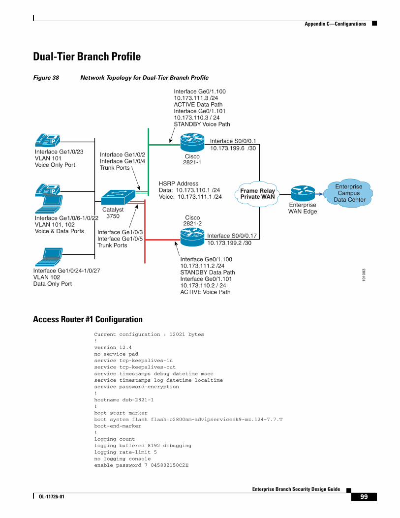
Appendix C—Configurations
Dual-Tier Branch Profile
Figure 38 Network Topology for Dual-Tier Branch Profile
Access Router #1 Configuration
Current configuration : 12021 bytes!version 12.4no service padservice tcp-keepalives-inservice tcp-keepalives-outservice timestamps debug datetime msecservice timestamps log datetime localtimeservice password-encryption!hostname dsb-2821-1!boot-start-markerboot system flash flash:c2800nm-advipservicesk9-mz.124-7.7.Tboot-end-marker!logging countlogging buffered 8192 debugginglogging rate-limit 5no logging consoleenable password 7 045802150C2E
1910
83
IP Frame RelayPrivate WAN
EnterpriseWAN Edge
Enterprise Campus
Data Center
IP
Catalyst3750
Cisco2821-1
Cisco2821-2
Interface Ge1/0/23VLAN 101Voice Only Port
Interface Ge1/0/24-1/0/27VLAN 102Data Only Port
Interface Ge1/0/3 Interface Ge1/0/5Trunk Ports
Interface Ge1/0/2 Interface Ge1/0/4Trunk Ports
Interface Ge0/1.10010.173.111.3 /24 ACTIVE Data PathInterface Ge0/1.10110.173.110.3 / 24STANDBY Voice Path
Interface Ge0/1.10010.173.111.2 /24 STANDBY Data PathInterface Ge0/1.10110.173.110.2 / 24ACTIVE Voice Path
HSRP AddressData: 10.173.110.1 /24Voice: 10.173.111.1 /24
Interface S0/0/0.110.173.199.6 /30
Interface S0/0/0.1710.173.199.2 /30
Interface Ge1/0/6-1/0/22VLAN 101, 102Voice & Data Ports
99Enterprise Branch Security Design Guide
OL-11726-01

Appendix C—Configurations
!aaa new-model!!aaa authentication login ssh_users group tacacs+aaa accounting send stop-record authentication failureaaa accounting exec ssh_users stop-only group tacacs+aaa accounting commands 15 ssh_users stop-only group tacacs+!aaa session-id common!resource policy!clock timezone est -5no ip source-route!ip nbar port-map custom-03 tcp 5554 9996ip nbar port-map custom-02 udp 1434ip nbar port-map custom-01 tcp 3200 3201 3202 3203 3600ip nbar port-map netbios udp 135 137 138 139 445ip nbar port-map netbios tcp 137 139 445ip cefip dhcp relay information trust-all!ip dhcp pool data_lan network 10.173.111.0 255.255.255.0 dns-server 10.102.6.247 default-router 10.173.111.1!ip dhcp pool voice_lan network 10.173.110.0 255.255.255.0 dns-server 10.59.138.4 default-router 10.173.110.1 option 150 ip 10.59.138.51 domain-name cisco.com!no ip bootp serverno ip domain lookupip domain name ese.cisco.comip ssh time-out 60ip ssh authentication-retries 2ip ssh source-interface GigabitEthernet0/1ip inspect one-minute high 2000ip inspect hashtable-size 2048ip inspect tcp max-incomplete host 100 block-time 0ip inspect name FW appfw ap_fwip inspect name FW tcp router-trafficip inspect name FW udp router-trafficip inspect name FW dnsip inspect name FW icmpip inspect name FW kazaaip inspect name FW netbios-dgmip inspect name FW netbios-nsip inspect name FW netbios-ssnip inspect name FW sship inspect name FW telnet alert onip inspect name FW https audit-trail onip inspect name FW ftpip inspect name FW parameter max-sessions 1000ip ips deny-action ips-interfaceip ips signature 1107 0 disableip ips signature 2000 0 disableip ips signature 2001 0 disableip ips name DSB
100Enterprise Branch Security Design Guide
OL-11726-01

Appendix C—Configurations
login block-for 30 attempts 3 within 200login delay 2!appfw policy-name ap_fw application http strict-http action reset alarm content-type-verification match-req-rsp action allow alarm port-misuse default action reset alarm!crypto pki trustpoint TP-self-signed-1127387955 enrollment selfsigned subject-name cn=IOS-Self-Signed-Certificate-1127387955 revocation-check none rsakeypair TP-self-signed-1127387955!crypto pki certificate chain TP-self-signed-1127387955 certificate self-signed 01 quitusername cisco password 7 14141B180F0B!class-map match-all BRANCH-BULK-DATA match access-group name BULK-DATA-APPSclass-map match-all SQL-SLAMMER match protocol custom-02 match packet length min 404 max 404class-map match-all BULK-DATA match ip dscp af11 af12class-map match-all INTERACTIVE-VIDEO match ip dscp af41 af42class-map match-any CALL-SIGNALLING match ip dscp cs3 match ip dscp af31class-map match-any BRANCH-SCAVENGER match protocol napster match protocol gnutella match protocol fasttrack match protocol kazaa2class-map match-all NET-MGMG match ip dscp af21 af22class-map match-any BRANCH-TRANSACTIONAL-DATA match protocol citrix match protocol ldap match protocol sqlnet match protocol http url "*cisco.com" match protocol custom-01class-map match-all BRANCH-MISSION-CRITICAL match access-group name MISSION-CRITICAL-SERVERSclass-map match-any WORMS match protocol http url "*.ida*" match protocol http url "*cmd.exe*" match protocol http url "*root.exe*" match protocol http url "*readme.eml*" match class-map SQL-SLAMMER match protocol exchange match protocol netbios match protocol custom-03class-map match-all VOICE match ip dscp ef match ip precedence 5class-map match-all MISSION-CRITICAL-DATA match ip dscp 25class-map match-any BRANCH-NET-MGMT match protocol snmp match protocol syslog
101Enterprise Branch Security Design Guide
OL-11726-01

Appendix C—Configurations
match protocol telnet match protocol nfs match protocol dns match protocol icmp match protocol tftpclass-map match-all ROUTING match ip dscp cs6class-map match-all SCAVENGER match ip dscp cs1!policy-map BRANCH-LAN-EDGE-OUT class CLASS-DEFAULT set cos dscppolicy-map BRANCH-LAN-EDGE-IN class BRANCH-MISSION-CRITICAL set ip dscp 25 class BRANCH-TRANSACTIONAL-DATA set ip dscp af21 class BRANCH-NET-MGMT set ip dscp cs2 class BRANCH-BULK-DATA set ip dscp af11 class BRANCH-SCAVENGER set ip dscp cs1 class WORMS drop class CLASS-DEFAULT set ip dscp defaultpolicy-map BRANCH-WAN-EDGE class VOICE priority percent 18 class INTERACTIVE-VIDEO priority percent 15 class CALL-SIGNALLING bandwidth percent 5 class ROUTING bandwidth percent 3 class NET-MGMG bandwidth percent 2 class MISSION-CRITICAL-DATA bandwidth percent 12 random-detect dscp-based class BULK-DATA bandwidth percent 4 random-detect dscp-based class SCAVENGER bandwidth percent 1 class CLASS-DEFAULT bandwidth percent 25 random-detect policy-map WAN_EDGE_FRTS class CLASS-DEFAULT shape average 1460000 14600 0 service-policy BRANCH-WAN-EDGE!interface Loopback0 bandwidth 6220000 ip address 10.173.112.1 255.255.255.255 no ip redirects no ip unreachables no ip proxy-arp ip virtual-reassembly ip route-cache flow!
102Enterprise Branch Security Design Guide
OL-11726-01

Appendix C—Configurations
interface GigabitEthernet0/1 no ip address duplex auto speed auto!interface GigabitEthernet0/1.100 description data encapsulation dot1Q 102 ip address 10.173.110.3 255.255.255.0 ip access-group DATA_LAN in no ip redirects no ip unreachables no ip proxy-arp ip ips DSB in ip virtual-reassembly delay 500 no snmp trap link-status standby 100 ip 10.173.110.1 standby 100 priority 90 standby 100 preempt!interface GigabitEthernet0/1.101 description voice encapsulation dot1Q 101 ip address 10.173.111.3 255.255.255.0 ip access-group VOICE_LAN in ip virtual-reassembly no snmp trap link-status standby 101 ip 10.173.111.1 standby 101 priority 120 standby 101 preempt standby 101 track Serial0/0/0.17 50!interface Serial0/0/0 no ip address encapsulation frame-relay no keepalive!interface Serial0/0/0.17 point-to-point ip address 10.173.199.2 255.255.255.252 no ip redirects no ip unreachables no ip proxy-arp ip access-group INET-WAN in ip inspect FW out ip ips DSB in ip virtual-reassembly frame-relay interface-dlci 17 class FRAME_MAP_T1!router eigrp 20 network 10.0.0.0 auto-summary!ip route 0.0.0.0 0.0.0.0 172.26.186.1!no ip http serverip http secure-serverip tacacs source-interface Loopback0!!map-class frame-relay FRAME_MAP_T1 service-policy output WAN_EDGE_FRTS!
103Enterprise Branch Security Design Guide
OL-11726-01

Appendix C—Configurations
ip access-list extended BULK-DATA-APPS permit tcp any any eq ftp permit tcp any any eq ftp-data permit tcp any any eq pop3 permit tcp any any eq 143ip access-list extended DATA_LAN permit udp host 0.0.0.0 host 255.255.255.255 permit ip 10.173.110.0 0.0.0.255 any deny ip any any ip access-list extended INET-WAN permit eigrp any any permit icmp any host 10.173.199.2 permit icmp any host 10.173.199.2 packet-too-big permit icmp any host 10.173.199.2 unreachable permit icmp any host 10.173.199.2 echo-reply permit icmp any host 10.173.199.2 time-exceeded permit icmp any 10.173.110.0 0.0.0.255 permit icmp any 10.173.110.0 0.0.0.255 packet-too-big permit icmp any 10.173.110.0 0.0.0.255 unreachable permit icmp any 10.173.110.0 0.0.0.255 echo-reply permit icmp any 10.173.110.0 0.0.0.255 time-exceeded permit icmp any 10.173.111.0 0.0.0.255 permit icmp any 10.173.111.0 0.0.0.255 packet-too-big permit icmp any 10.173.111.0 0.0.0.255 unreachable permit icmp any 10.173.111.0 0.0.0.255 echo-reply permit icmp any 10.173.111.0 0.0.0.255 time-exceeded permit udp any host 10.173.199.2 eq ntp permit udp any host 10.173.199.2 eq 22 permit tcp any host 10.173.199.2 eq 22 deny ip host 255.255.255.255 any permit ip any 10.173.110.0 0.0.0.255 permit ip any 10.173.111.0 0.0.0.255 deny ip any any deny ip any any ip access-list extended MISSION-CRITICAL-SERVERS permit ip any 10.173.110.0 0.0.0.255 permit ip any 10.173.111.0 0.0.0.255ip access-list extended VOICE_LAN permit udp host 0.0.0.0 host 255.255.255.255 permit ip 10.173.111.0 0.0.0.255 any deny ip any any !tacacs-server host 10.59.138.11tacacs-server directed-requesttacacs-server key 7 13061E010803557878!control-plane!line con 0line aux 0line vty 0 4 exec-timeout 120 0 password 7 1511021F0725 accounting commands 15 ssh_users accounting exec ssh_users login authentication ssh_users exec prompt timestamp transport input ssh transport output all!scheduler allocate 20000 1000ntp clock-period 17180238ntp server 10.173.129.1!
104Enterprise Branch Security Design Guide
OL-11726-01
Appendix C—Configurations
webvpn context dummy ssl authenticate verify all ! no inservice!!end
Access Router #2 Configuration
Current configuration : 9149 bytes!version 12.4no service padservice tcp-keepalives-inservice tcp-keepalives-outservice timestamps debug datetime msecservice timestamps log datetime localtimeservice password-encryption!hostname dsb-2821-2!boot-start-markerboot system flash flash:c2800nm-advipservicesk9-mz.124-7.7.Tboot-end-marker!logging countlogging buffered 8192 debugginglogging rate-limit 5no logging consoleenable secret 5 $1$ltwT$FuwMFsxBk7Zn5QZ/ma.Rl.!aaa new-model!!aaa authentication login ssh_users group tacacs+aaa accounting send stop-record authentication failureaaa accounting exec ssh_users stop-only group tacacs+aaa accounting commands 15 ssh_users stop-only group tacacs+!aaa session-id common!resource policy!clock timezone est -5no ip source-route!ip nbar port-map custom-03 tcp 5554 9996ip nbar port-map custom-02 udp 1434ip nbar port-map custom-01 tcp 3200 3201 3202 3203 3600ip nbar port-map netbios udp 135 137 138 139 445ip nbar port-map netbios tcp 137 139 445ip cefip dhcp relay information trust-all!ip dhcp pool data_lan network 10.173.110.0 255.255.255.0 dns-server 10.59.138.4 default-router 10.173.110.1!ip dhcp pool voice_lan
105Enterprise Branch Security Design Guide
OL-11726-01

Appendix C—Configurations
network 10.173.111.0 255.255.255.0 dns-server 10.59.138.51 option 150 ip 10.59.138.51 default-router 10.173.111.1 domain-name cisco.com!no ip bootp serverno ip domain lookupip domain name ese.cisco.comip ssh time-out 60ip ssh authentication-retries 2ip ssh source-interface GigabitEthernet0/1ip inspect one-minute high 2000ip inspect tcp max-incomplete host 100 block-time 0ip inspect name FW appfw ap_fwip inspect name FW tcp router-trafficip inspect name FW udp router-trafficip inspect name FW dnsip inspect name FW icmpip inspect name FW kazaaip inspect name FW netbios-dgmip inspect name FW netbios-nsip inspect name FW netbios-ssnip inspect name FW sship inspect name FW telnet alert onip inspect name FW https audit-trail onip inspect name FW ftpip inspect name FW parameter max-sessions 1000ip ips deny-action ips-interfaceip ips signature 1107 0 disableip ips signature 2000 0 disableip ips signature 2001 0 disableip ips name DSBlogin block-for 30 attempts 3 within 200login delay 2!appfw policy-name ap_fw application http strict-http action reset alarm content-type-verification match-req-rsp action allow alarm port-misuse default action reset alarm!
crypto pki trustpoint TP-self-signed-3757792988 enrollment selfsigned subject-name cn=IOS-Self-Signed-Certificate-3757792988 revocation-check none rsakeypair TP-self-signed-3757792988!crypto pki certificate chain TP-self-signed-3757792988 certificate self-signed 01 quitusername cisco password 7 060506324F41!class-map match-all BRANCH-BULK-DATA match access-group name BULK-DATA-APPSclass-map match-all SQL-SLAMMER match protocol custom-02 match packet length min 404 max 404class-map match-all BULK-DATA match ip dscp af11 af12class-map match-all INTERACTIVE-VIDEO match ip dscp af41 af42class-map match-any CALL-SIGNALLING
106Enterprise Branch Security Design Guide
OL-11726-01

Appendix C—Configurations
match ip dscp cs3 match ip dscp af31class-map match-any BRANCH-SCAVENGER match protocol napster match protocol gnutella match protocol fasttrack match protocol kazaa2class-map match-all NET-MGMG match ip dscp af21 af22class-map match-any BRANCH-TRANSACTIONAL-DATA match protocol citrix match protocol ldap match protocol sqlnet match protocol http url "*cisco.com" match protocol custom-01class-map match-all BRANCH-MISSION-CRITICAL match access-group name MISSION-CRITICAL-SERVERSclass-map match-any WORMS match protocol http url "*.ida*" match protocol http url "*cmd.exe*" match protocol http url "*root.exe*" match protocol http url "*readme.eml*" match class-map SQL-SLAMMER match protocol exchange match protocol netbios match protocol custom-03class-map match-all VOICE match ip dscp ef match ip precedence 5class-map match-all MISSION-CRITICAL-DATA match ip dscp 25class-map match-any BRANCH-NET-MGMT match protocol snmp match protocol syslog match protocol telnet match protocol nfs match protocol dns match protocol icmp match protocol tftpclass-map match-all ROUTING match ip dscp cs6class-map match-all SCAVENGER match ip dscp cs1!policy-map BRANCH-LAN-EDGE-OUT class CLASS-DEFAULT set cos dscppolicy-map BRANCH-LAN-EDGE-IN class BRANCH-MISSION-CRITICAL set ip dscp 25 class BRANCH-TRANSACTIONAL-DATA set ip dscp af21 class BRANCH-NET-MGMT set ip dscp cs2 class BRANCH-BULK-DATA set ip dscp af11 class BRANCH-SCAVENGER set ip dscp cs1 class WORMS drop class CLASS-DEFAULT set ip dscp defaultpolicy-map BRANCH-WAN-EDGE class VOICE
107Enterprise Branch Security Design Guide
OL-11726-01

Appendix C—Configurations
priority percent 18 class INTERACTIVE-VIDEO priority percent 15 class CALL-SIGNALLING bandwidth percent 5 class ROUTING bandwidth percent 3 class NET-MGMG bandwidth percent 2 class MISSION-CRITICAL-DATA bandwidth percent 12 random-detect dscp-based class BULK-DATA bandwidth percent 4 random-detect dscp-based class SCAVENGER bandwidth percent 1 class CLASS-DEFAULT bandwidth percent 25 random-detect policy-map WAN_EDGE_FRTS class CLASS-DEFAULT shape average 1460000 14600 0 service-policy BRANCH-WAN-EDGE!interface Loopback0 ip address 10.173.112.2 255.255.255.255!interface GigabitEthernet0/1 no ip address duplex auto speed auto!interface GigabitEthernet0/1.100 description data encapsulation dot1Q 102 ip address 10.173.110.2 255.255.255.0 no ip redirects no ip unreachables no ip proxy-arp ip ips DSB in ip virtual-reassembly no snmp trap link-status standby 100 ip 10.173.110.1 standby 100 priority 120 standby 100 preempt standby 100 track Serial0/0/0.1 50!interface GigabitEthernet0/1.101 description voice encapsulation dot1Q 101 ip address 10.173.111.2 255.255.255.0 no ip redirects no ip unreachables no ip proxy-arp ip ips DSB in ip virtual-reassembly delay 500 no snmp trap link-status standby 101 ip 10.173.111.1 standby 101 preempt!interface Serial0/0/0 no ip address
108Enterprise Branch Security Design Guide
OL-11726-01

Appendix C—Configurations
encapsulation frame-relay!interface Serial0/0/0.1 point-to-point ip address 10.173.199.6 255.255.255.252 ip access-group INET-WAN in no ip redirects no ip unreachables no ip proxy-arp ip inspect FW out ip ips DSB in ip virtual-reassembly frame-relay interface-dlci 17 class FRAME_MAP_T1!router eigrp 20 network 10.0.0.0 no auto-summary!no ip http serverip http secure-serverip tacacs source-interface Loopback0!map-class frame-relay FRAME_MAP_T1 service-policy output WAN_EDGE_FRTS!ip access-list extended BULK-DATA-APPS permit tcp any any eq ftp permit tcp any any eq ftp-data permit tcp any any eq pop3 permit tcp any any eq 143ip access-list extended MISSION-CRITICAL-SERVERS permit ip any 10.173.110.0 0.0.0.255 permit ip any 10.173.111.0 0.0.0.255ip access-list extended VOICE-LAN permit udp host 0.0.0.0 host 255.255.255.255 permit ip 10.173.111.0 0.0.0.255 any deny ip any any ip access-list extended INET-WAN permit eigrp any any permit icmp any host 10.173.199.6 permit icmp any host 10.173.199.6 packet-too-big permit icmp any host 10.173.199.6 unreachable permit icmp any host 10.173.199.6 echo-reply permit icmp any host 10.173.199.6 time-exceeded permit icmp any 10.173.110.0 0.0.0.255 permit icmp any 10.173.110.0 0.0.0.255 packet-too-big permit icmp any 10.173.110.0 0.0.0.255 unreachable permit icmp any 10.173.110.0 0.0.0.255 echo-reply permit icmp any 10.173.110.0 0.0.0.255 time-exceeded permit icmp any 10.173.111.0 0.0.0.255 permit icmp any 10.173.111.0 0.0.0.255 packet-too-big permit icmp any 10.173.111.0 0.0.0.255 unreachable permit icmp any 10.173.111.0 0.0.0.255 echo-reply permit icmp any 10.173.111.0 0.0.0.255 time-exceeded permit udp any host 10.173.199.6 eq ntp permit udp any host 10.173.199.6 eq 22 permit tcp any host 10.173.199.6 eq 22 deny ip host 255.255.255.255 any permit ip any 10.173.110.0 0.0.0.255 permit ip any 10.173.111.0 0.0.0.255 deny ip any any deny ip any any ip access-list extended DATA_LAN permit udp host 0.0.0.0 host 255.255.255.255
109Enterprise Branch Security Design Guide
OL-11726-01
Appendix C—Configurations
permit ip 10.173.110.0 0.0.0.255 any deny ip any any !tacacs-server host 10.59.138.11tacacs-server directed-requesttacacs-server key 7 13061E010803557878!control-plane!line con 0line aux 0line vty 0 4 exec-timeout 120 0 password 7 1511021F0725 accounting exec ssh_users login authentication ssh_users exec prompt timestamp transport input ssh transport output all!scheduler allocate 20000 1000ntp clock-period 17180215ntp server 10.173.129.1!webvpn context dummy ssl authenticate verify all ! no inservice!!end
External Switch Configuration
Current configuration : 22567 bytes
version 12.2no service padservice tcp-keepalives-inservice tcp-keepalives-outservice timestamps debug uptimeservice timestamps log uptimeservice password-encryption!hostname dsb-3750-1!logging countlogging buffered 8192 debugginglogging rate-limit 5no logging consoleenable password 7 110A1016141D!username cisco password 7 070C285F4D06no aaa new-modelclock timezone est -5switch 1 provision ws-c3750g-24tsvtp domain ese_branchvtp mode transparentip subnet-zeroip routingno ip domain-lookup
110Enterprise Branch Security Design Guide
OL-11726-01

Appendix C—Configurations
ip domain-name ese.cisco.comip dhcp smart-relay!ip dhcp snooping vlan 101-102ip dhcp snooping database flash:dhcp.txtip dhcp snooping database timeout 10ip dhcp snoopingip ssh time-out 60ip ssh authentication-retries 2ip ssh source-interface Vlan186ip arp inspection vlan 101-102ip arp inspection validate src-macip arp inspection log-buffer entries 100ip arp inspection log-buffer logs 20 interval 120login block-for 30 attempts 3 within 200login delay 2!mls qos map policed-dscp 0 10 18 24 25 34 to 8mls qos map cos-dscp 0 8 16 24 32 46 48 56mls qos srr-queue output cos-map queue 1 threshold 3 5mls qos srr-queue output cos-map queue 2 threshold 1 2 4mls qos srr-queue output cos-map queue 2 threshold 2 3mls qos srr-queue output cos-map queue 2 threshold 3 6 7mls qos srr-queue output cos-map queue 3 threshold 3 0mls qos srr-queue output cos-map queue 4 threshold 3 1mls qos srr-queue output dscp-map queue 1 threshold 3 46mls qos srr-queue output dscp-map queue 2 threshold 1 16 18 20 22 25 32 34 36mls qos srr-queue output dscp-map queue 2 threshold 1 38mls qos srr-queue output dscp-map queue 2 threshold 2 24 26mls qos srr-queue output dscp-map queue 2 threshold 3 48 56mls qos srr-queue output dscp-map queue 3 threshold 3 0mls qos srr-queue output dscp-map queue 4 threshold 1 8mls qos srr-queue output dscp-map queue 4 threshold 3 10 12 14mls qos queue-set output 1 threshold 2 70 80 100 100mls qos queue-set output 1 threshold 4 40 100 100 100mls qos!crypto pki trustpoint TP-self-signed-2200782592 enrollment selfsigned subject-name cn=IOS-Self-Signed-Certificate-2200782592 revocation-check none rsakeypair TP-self-signed-2200782592!
crypto ca certificate chain TP-self-signed-2200782592 certificate self-signed 01 quit!errdisable recovery cause link-flaperrdisable recovery interval 60no file verify auto!spanning-tree mode rapid-pvstspanning-tree loopguard defaultspanning-tree portfast bpduguard defaultno spanning-tree optimize bpdu transmissionspanning-tree extend system-id!vlan internal allocation policy ascending!vlan 101 name voice!vlan 102
111Enterprise Branch Security Design Guide
OL-11726-01

Appendix C—Configurations
name data!class-map match-all DVLAN-PC-VIDEO match access-group name DVLAN-PC-VIDEOclass-map match-all VVLAN-VOICE match access-group name VVLAN-VOICEclass-map match-all VVLAN-ANY match access-group name VVLAN-ANYclass-map match-all DVLAN-TRANSACTIONAL-DATA match access-group name DVLAN-TRANSACTIONAL-DATAclass-map match-all DVLAN-MISSION-CRITICAL-DATA match access-group name DVLAN-MISSION-CRITICAL-DATAclass-map match-all DVLAN-BULK-DATA match access-group name DVLAN-BULK-DATAclass-map match-all VVLAN-CALL-SIGNALLING match access-group name VVLAN-CALL-SIGNALLING!policy-map IPPHONE+PC class VVLAN-VOICE set dscp ef police 128000 8000 exceed-action drop class VVLAN-CALL-SIGNALLING set dscp cs3 police 32000 8000 exceed-action policed-dscp-transmit class VVLAN-ANY set dscp default police 32000 8000 exceed-action policed-dscp-transmit class DVLAN-PC-VIDEO set dscp af41 police 48000 8000 exceed-action policed-dscp-transmit class DVLAN-MISSION-CRITICAL-DATA set dscp 25 police 5000000 8000 exceed-action policed-dscp-transmit class DVLAN-TRANSACTIONAL-DATA set dscp af21 police 5000000 8000 exceed-action policed-dscp-transmit class DVLAN-BULK-DATA set dscp af11 police 5000000 8000 exceed-action policed-dscp-transmit!interface GigabitEthernet1/0/1 switchport trunk encapsulation dot1q switchport mode trunk switchport port-security aging time 10 ip arp inspection trust load-interval 30 srr-queue bandwidth share 1 70 25 5 srr-queue bandwidth shape 3 0 0 0 priority-queue out ip dhcp snooping limit rate 10 ip dhcp snooping trust!interface GigabitEthernet1/0/2 switchport trunk encapsulation dot1q switchport mode trunk switchport port-security aging time 10 ip arp inspection trust load-interval 30 srr-queue bandwidth share 1 70 25 5 srr-queue bandwidth shape 3 0 0 0 priority-queue out ip dhcp snooping limit rate 10 ip dhcp snooping trust!
112Enterprise Branch Security Design Guide
OL-11726-01

Appendix C—Configurations
interface GigabitEthernet1/0/3 switchport trunk encapsulation dot1q switchport mode trunk switchport port-security aging time 10 ip arp inspection trust load-interval 30 srr-queue bandwidth share 1 70 25 5 srr-queue bandwidth shape 3 0 0 0 priority-queue out ip dhcp snooping limit rate 10 ip dhcp snooping trust!interface GigabitEthernet1/0/4 switchport trunk encapsulation dot1q switchport mode trunk switchport port-security aging time 10 ip arp inspection trust load-interval 30 srr-queue bandwidth share 1 70 25 5 srr-queue bandwidth shape 3 0 0 0 priority-queue out ip dhcp snooping limit rate 10 ip dhcp snooping trust!interface GigabitEthernet1/0/6 - interface GigabitEthernet1/0/23 description phone with PC connected to phone switchport access vlan 102 switchport mode access switchport voice vlan 101 switchport port-security maximum 2 switchport port-security switchport port-security aging time 2 switchport port-security violation restrict switchport port-security aging type inactivity ip arp inspection limit rate 100 load-interval 30 srr-queue bandwidth share 1 70 25 5 srr-queue bandwidth shape 3 0 0 0 priority-queue out mls qos trust device cisco-phone spanning-tree portfast spanning-tree bpduguard enable ip verify source ip dhcp snooping limit rate 100!interface GigabitEthernet1/0/24- interface GigabitEthernet1/0/28 description DATA only ports switchport access vlan 102 switchport mode access switchport port-security maximum 3 switchport port-security switchport port-security aging time 2 switchport port-security violation restrict switchport port-security aging type inactivity ip arp inspection limit rate 100 load-interval 30 srr-queue bandwidth share 1 70 25 5 srr-queue bandwidth shape 3 0 0 0 priority-queue out spanning-tree portfast spanning-tree bpduguard enable ip verify source ip dhcp snooping limit rate 100!
113Enterprise Branch Security Design Guide
OL-11726-01

Appendix C—Configurations
interface Vlan1 no ip address!ip classlessno ip http serverip http secure-server!ip access-list extended DVLAN-BULK-DATA permit tcp any any eq 143 permit tcp any any eq 220ip access-list extended DVLAN-MISSION-CRITICAL-DATA permit tcp any any range 3200 3203 permit tcp any any eq 3600 permit tcp any any range 2000 2002ip access-list extended DVLAN-PC-VIDEO permit udp any any range 16384 32767ip access-list extended DVLAN-TRANSACTIONAL-DATA permit tcp any any eq 1352ip access-list extended VVLAN-ANY permit ip 10.1.110.0 0.0.0.255 anyip access-list extended VVLAN-CALL-SIGNALING permit tcp 10.1.110.0 0.0.0.255 any range 2000 2002ip access-list extended VVLAN-VOICE permit udp 10.1.110.0 0.0.0.255 any range 16384 32767ip access-list extended VVLAN-ANY permit ip 10.173.111.0 0.0.0.255 anyip access-list extended VVLAN-CALL-SIGNALLING permit tcp 10.173.111.0 0.0.0.255 any range 2000 2002 dscp af31 permit tcp 10.173.111.0 0.0.0.255 any range 2000 2002 dscp cs3ip access-list extended VVLAN-VOICE permit udp 10.173.111.0 0.0.0.255 any range 16384 32767 dscp ef!control-plane!line con 0line vty 0 4 password 7 02050D480809 no login exec prompt timestamp transport input telnet sshline vty 5 15 password 7 02050D480809 no login exec prompt timestamp transport input telnet ssh!ntp clock-period 36029397ntp server 172.26.186.10end
114Enterprise Branch Security Design Guide
OL-11726-01
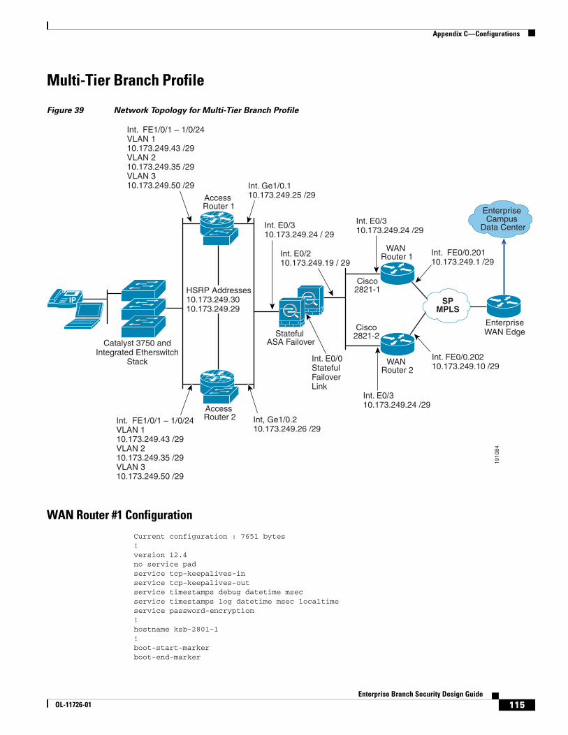
Appendix C—Configurations
Multi-Tier Branch Profile
Figure 39 Network Topology for Multi-Tier Branch Profile
WAN Router #1 Configuration
Current configuration : 7651 bytes!version 12.4no service padservice tcp-keepalives-inservice tcp-keepalives-outservice timestamps debug datetime msecservice timestamps log datetime msec localtimeservice password-encryption!hostname ksb-2801-1!boot-start-markerboot-end-marker
1910
84
Catalyst 3750 andIntegrated Etherswitch
Stack
Int. FE1/0/1 – 1/0/24VLAN 110.173.249.43 /29VLAN 210.173.249.35 /29VLAN 310.173.249.50 /29
Int. FE1/0/1 – 1/0/24VLAN 110.173.249.43 /29VLAN 210.173.249.35 /29VLAN 310.173.249.50 /29
Int. Ge1/0.110.173.249.25 /29
Int, Ge1/0.210.173.249.26 /29
Int. E0/310.173.249.24 / 29
Int. E0/310.173.249.24 /29
Int. E0/310.173.249.24 /29
Int. FE0/0.20110.173.249.1 /29
Int. FE0/0.20210.173.249.10 /29
HSRP Addresses10.173.249.3010.173.249.29
Int. E0/0StatefulFailoverLink
Int. E0/210.173.249.19 / 29
IP SPMPLS
EnterpriseWAN Edge
Enterprise Campus
Data Center
Access Router 1
Access Router 2
WAN Router 1
WAN Router 2
Cisco2821-1
Cisco2821-2Stateful
ASA Failover
115Enterprise Branch Security Design Guide
OL-11726-01
Appendix C—Configurations
!logging countlogging buffered 8192 debugginglogging rate-limit 5no logging consoleenable password 7 045802150C2E!aaa new-model!!aaa authentication login ssh_users group tacacs+aaa accounting send stop-record authentication failureaaa accounting exec ssh_users stop-only group tacacs+aaa accounting commands 15 ssh_users stop-only group tacacs+!aaa session-id common!resource policy!clock timezone est -5no ip source-route!ip nbar port-map custom-03 tcp 5554 9996ip nbar port-map custom-02 udp 1434ip nbar port-map custom-01 tcp 3200 3201 3202 3203 3600ip nbar port-map netbios udp 135 137 138 139 445ip nbar port-map netbios tcp 137 139 445ip cef!logging buffered 65535 debugginglogging rate-limit all 20enable secret 5 $1$./PL$wO4j2/f8KIS2Plt8NYPh0.!no ip domain lookup!!!no ip bootp serverno ip domain lookupip domain name ese.cisco.comip ssh time-out 60ip ssh authentication-retries 2ip ssh source-interface FastEthernet0/0ip ips deny-action ips-interfaceip ips signature 1107 0 disableip ips signature 2000 0 disableip ips signature 2001 0 disableip ips name KSBlogin block-for 30 attempts 3 within 200login delay 2!!!track 10 rtr 10 reachability delay up 120!track 15 ip route 10.57.100.0 255.255.254.0 reachability delay up 90!track 20 interface FastEthernet0/3/3 line-protocol!track 30 list boolean and object 10 object 20
116Enterprise Branch Security Design Guide
OL-11726-01

Appendix C—Configurations
!username cisco password 7 14141B180F0B!class-map match-all BRANCH-BULK-DATA match access-group name BULK-DATA-APPSclass-map match-all SQL-SLAMMER match protocol custom-02 match packet length min 404 max 404class-map match-all BULK-DATA match ip dscp af11 af12class-map match-all INTERACTIVE-VIDEO match ip dscp af41 af42class-map match-any CALL-SIGNALLING match ip dscp cs3 match ip dscp af31class-map match-any BRANCH-SCAVENGER match protocol napster match protocol gnutella match protocol fasttrack match protocol kazaa2class-map match-all NET-MGMG match ip dscp af21 af22class-map match-any BRANCH-TRANSACTIONAL-DATA match protocol citrix match protocol ldap match protocol sqlnet match protocol http url "*cisco.com" match protocol custom-01class-map match-all BRANCH-MISSION-CRITICAL match access-group name MISSION-CRITICAL-SERVERSclass-map match-any WORMS match protocol http url "*.ida*" match protocol http url "*cmd.exe*" match protocol http url "*root.exe*" match protocol http url "*readme.eml*" match class-map SQL-SLAMMER match protocol exchange match protocol netbios match protocol custom-03class-map match-all VOICE match ip dscp ef match ip precedence 5class-map match-all MISSION-CRITICAL-DATA match ip dscp 25class-map match-any BRANCH-NET-MGMT match protocol snmp match protocol syslog match protocol telnet match protocol nfs match protocol dns match protocol icmp match protocol tftpclass-map match-all ROUTING match ip dscp cs6class-map match-all SCAVENGER match ip dscp cs1!policy-map BRANCH-LAN-EDGE-OUT class CLASS-DEFAULT set cos dscppolicy-map BRANCH-LAN-EDGE-IN class BRANCH-MISSION-CRITICAL set ip dscp 25 class BRANCH-TRANSACTIONAL-DATA
117Enterprise Branch Security Design Guide
OL-11726-01

Appendix C—Configurations
set ip dscp af21 class BRANCH-NET-MGMT set ip dscp cs2 class BRANCH-BULK-DATA set ip dscp af11 class BRANCH-SCAVENGER set ip dscp cs1 class WORMS drop class CLASS-DEFAULT set ip dscp defaultpolicy-map BRANCH-WAN-EDGE class VOICE priority percent 18 class INTERACTIVE-VIDEO priority percent 15 class CALL-SIGNALLING bandwidth percent 5 class ROUTING bandwidth percent 3 class NET-MGMG bandwidth percent 2 class MISSION-CRITICAL-DATA bandwidth percent 12 random-detect dscp-based class BULK-DATA bandwidth percent 4 random-detect dscp-based class SCAVENGER bandwidth percent 1 class CLASS-DEFAULT bandwidth percent 25 random-detect!!interface FastEthernet0/0 no ip address duplex auto speed auto max-reserved-bandwidth 100 service-policy output BRANCH-WAN-EDGE!!interface FastEthernet0/0.201 encapsulation dot1Q 201 ip address 10.173.249.1 255.255.255.248 no ip redirects no ip unreachables no ip proxy-arp ip access-group NOT_LOCAL_NETS in ip access-group LOCAL_NETS out ip ips KSB in no snmp trap link-status!interface FastEthernet0/1 no ip address duplex auto speed auto!interface FastEthernet0/3/0 shutdown!interface FastEthernet0/3/1 switchport access vlan 20
118Enterprise Branch Security Design Guide
OL-11726-01

Appendix C—Configurations
!interface FastEthernet0/3/2 spanning-tree portfast!interface FastEthernet0/3/3 spanning-tree portfast!interface Vlan1 ip address 10.173.249.17 255.255.255.248 standby 1 ip 10.173.249.22 standby 1 priority 110 standby 1 preempt standby 1 track 15 decrement 20!router eigrp 30 redistribute static metric 15000 100 255 1 1500 network 10.0.0.0 no auto-summary eigrp stub connected static!ip route 10.173.192.0 255.255.192.0 10.173.249.19 track 30ip route 10.100.0.0 255.255.0.0 10.173.249.19ip route 10.173.249.29 255.255.255.255 10.173.249.19!!ip http serverno ip http secure-serverip tacacs source-interface Vlan1!ip access-list extended BULK-DATA-APPS permit tcp any any eq ftp permit tcp any any eq ftp-data permit tcp any any eq pop3 permit tcp any any eq 143!ip access-list extended MISSION-CRITICAL-SERVERS permit ip any 10.173.110.0 0.0.0.255 permit ip any 10.173.111.0 0.0.0.255ip access-list extended LOCAL_NETS deny icmp any 10.173.249.8 0.0.0.7 permit ip any 10.173.192.0 0.0.63.255 permit ip 10.173.192.0 0.0.63.255 any deny ip any anyip access-list extended NOT_LOCAL_NETS permit eigrp any any permit ip 10.173.249.8 0.0.0.7 10.173.249.8 0.0.0.7 remark prevent smurfs deny ip 10.173.192.0 0.0.63.255 any log permit ip any 10.173.192.0 0.0.0.63 permit ip any 10.173.192.0 0.0.63.255!ip sla 10 icmp-echo 10.173.249.29 timeout 500 frequency 10ip sla schedule 10 life forever start-time now!!!tacacs-server host 10.59.138.11tacacs-server directed-requesttacacs-server key 7 13061E010803557878!control-plane
119Enterprise Branch Security Design Guide
OL-11726-01
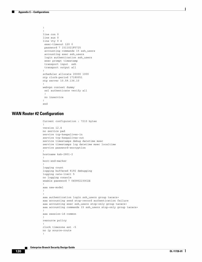
Appendix C—Configurations
!!line con 0line aux 0line vty 0 4 exec-timeout 120 0 password 7 1511021F0725 accounting commands 15 ssh_users accounting exec ssh_users login authentication ssh_users exec prompt timestamp transport input ssh transport output all!scheduler allocate 20000 1000ntp clock-period 17180051ntp server 10.59.136.10!webvpn context dummy ssl authenticate verify all ! no inservice!end
WAN Router #2 Configuration
Current configuration : 7210 bytes!version 12.4no service padservice tcp-keepalives-inservice tcp-keepalives-outservice timestamps debug datetime msecservice timestamps log datetime msec localtimeservice password-encryption!hostname ksb-2801-2!boot-end-marker!logging countlogging buffered 8192 debugginglogging rate-limit 5no logging consoleenable password 7 045802150C2E!aaa new-model!!aaa authentication login ssh_users group tacacs+aaa accounting send stop-record authentication failureaaa accounting exec ssh_users stop-only group tacacs+aaa accounting commands 15 ssh_users stop-only group tacacs+!aaa session-id common!resource policy!clock timezone est -5no ip source-route!
120Enterprise Branch Security Design Guide
OL-11726-01

Appendix C—Configurations
ip nbar port-map custom-03 tcp 5554 9996ip nbar port-map custom-02 udp 1434ip nbar port-map custom-01 tcp 3200 3201 3202 3203 3600ip nbar port-map netbios udp 135 137 138 139 445ip nbar port-map netbios tcp 137 139 445ip cef!logging buffered 65535 debugginglogging rate-limit all 20enable secret 5 $1$./PL$wO4j2/f8KIS2Plt8NYPh0.!!no ip bootp serverno ip domain lookupip domain name ese.cisco.comip ssh time-out 60ip ssh authentication-retries 2ip ssh source-interface FastEthernet0/0ip ips deny-action ips-interfaceip ips signature 1107 0 disableip ips signature 2000 0 disableip ips signature 2001 0 disableip ips name KSBlogin block-for 30 attempts 3 within 200login delay 2!!!ip domain name ese.cisco.com!track 10 rtr 10 reachability delay up 120!!username cisco password 7 14141B180F0B!class-map match-all BRANCH-BULK-DATA match access-group name BULK-DATA-APPSclass-map match-all SQL-SLAMMER match protocol custom-02 match packet length min 404 max 404class-map match-all BULK-DATA match ip dscp af11 af12class-map match-all INTERACTIVE-VIDEO match ip dscp af41 af42class-map match-any CALL-SIGNALLING match ip dscp cs3 match ip dscp af31class-map match-any BRANCH-SCAVENGER match protocol napster match protocol gnutella match protocol fasttrack match protocol kazaa2class-map match-all NET-MGMG match ip dscp af21 af22class-map match-any BRANCH-TRANSACTIONAL-DATA match protocol citrix match protocol ldap match protocol sqlnet match protocol http url "*cisco.com" match protocol custom-01class-map match-all BRANCH-MISSION-CRITICAL match access-group name MISSION-CRITICAL-SERVERSclass-map match-any WORMS
121Enterprise Branch Security Design Guide
OL-11726-01

Appendix C—Configurations
match protocol http url "*.ida*" match protocol http url "*cmd.exe*" match protocol http url "*root.exe*" match protocol http url "*readme.eml*" match class-map SQL-SLAMMER match protocol exchange match protocol netbios match protocol custom-03class-map match-all VOICE match ip dscp ef match ip precedence 5class-map match-all MISSION-CRITICAL-DATA match ip dscp 25class-map match-any BRANCH-NET-MGMT match protocol snmp match protocol syslog match protocol telnet match protocol nfs match protocol dns match protocol icmp match protocol tftpclass-map match-all ROUTING match ip dscp cs6class-map match-all SCAVENGER match ip dscp cs1!policy-map BRANCH-LAN-EDGE-OUT class CLASS-DEFAULT set cos dscppolicy-map BRANCH-LAN-EDGE-IN class BRANCH-MISSION-CRITICAL set ip dscp 25 class BRANCH-TRANSACTIONAL-DATA set ip dscp af21 class BRANCH-NET-MGMT set ip dscp cs2 class BRANCH-BULK-DATA set ip dscp af11 class BRANCH-SCAVENGER set ip dscp cs1 class WORMS drop class CLASS-DEFAULT set ip dscp defaultpolicy-map BRANCH-WAN-EDGE class VOICE priority percent 18 class INTERACTIVE-VIDEO priority percent 15 class CALL-SIGNALLING bandwidth percent 5 class ROUTING bandwidth percent 3 class NET-MGMG bandwidth percent 2 class MISSION-CRITICAL-DATA bandwidth percent 12 random-detect dscp-based class BULK-DATA bandwidth percent 4 random-detect dscp-based class SCAVENGER bandwidth percent 1 class CLASS-DEFAULT
122Enterprise Branch Security Design Guide
OL-11726-01
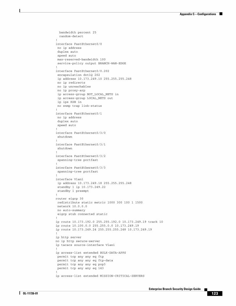
Appendix C—Configurations
bandwidth percent 25 random-detect!interface FastEthernet0/0 no ip address duplex auto speed auto max-reserved-bandwidth 100 service-policy output BRANCH-WAN-EDGE!interface FastEthernet0/0.202 encapsulation dot1Q 202 ip address 10.173.249.10 255.255.255.248 no ip redirects no ip unreachables no ip proxy-arp ip access-group NOT_LOCAL_NETS in ip access-group LOCAL_NETS out ip ips KSB in no snmp trap link-status!interface FastEthernet0/1 no ip address duplex auto speed auto!interface FastEthernet0/3/0 shutdown!interface FastEthernet0/3/1 shutdown!interface FastEthernet0/3/2 spanning-tree portfast!interface FastEthernet0/3/3 spanning-tree portfast!interface Vlan1 ip address 10.173.249.18 255.255.255.248 standby 1 ip 10.173.249.22 standby 1 preempt!router eigrp 30 redistribute static metric 1000 300 100 1 1500 network 10.0.0.0 no auto-summary eigrp stub connected static!ip route 10.173.192.0 255.255.192.0 10.173.249.19 track 10ip route 10.100.0.0 255.255.0.0 10.173.249.19ip route 10.173.249.24 255.255.255.248 10.173.249.19!ip http serverno ip http secure-serverip tacacs source-interface Vlan1!ip access-list extended BULK-DATA-APPS permit tcp any any eq ftp permit tcp any any eq ftp-data permit tcp any any eq pop3 permit tcp any any eq 143!ip access-list extended MISSION-CRITICAL-SERVERS
123Enterprise Branch Security Design Guide
OL-11726-01
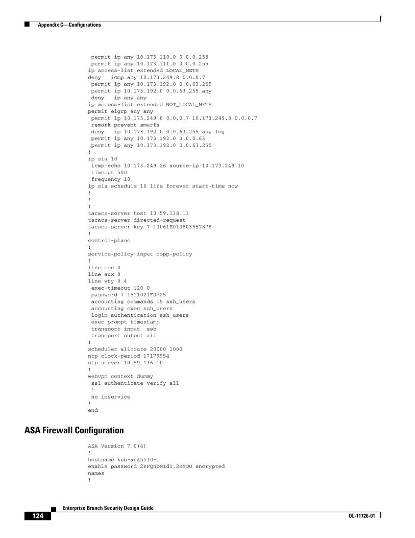
Appendix C—Configurations
permit ip any 10.173.110.0 0.0.0.255 permit ip any 10.173.111.0 0.0.0.255ip access-list extended LOCAL_NETSdeny icmp any 10.173.249.8 0.0.0.7 permit ip any 10.173.192.0 0.0.63.255 permit ip 10.173.192.0 0.0.63.255 any deny ip any anyip access-list extended NOT_LOCAL_NETSpermit eigrp any any permit ip 10.173.249.8 0.0.0.7 10.173.249.8 0.0.0.7 remark prevent smurfs deny ip 10.173.192.0 0.0.63.255 any log permit ip any 10.173.192.0 0.0.0.63 permit ip any 10.173.192.0 0.0.63.255!ip sla 10 icmp-echo 10.173.249.26 source-ip 10.173.249.10 timeout 500 frequency 10ip sla schedule 10 life forever start-time now!!!tacacs-server host 10.59.138.11tacacs-server directed-requesttacacs-server key 7 13061E010803557878!control-plane!service-policy input copp-policy!line con 0line aux 0line vty 0 4 exec-timeout 120 0 password 7 1511021F0725 accounting commands 15 ssh_users accounting exec ssh_users login authentication ssh_users exec prompt timestamp transport input ssh transport output all!scheduler allocate 20000 1000ntp clock-period 17179954ntp server 10.59.136.10!webvpn context dummy ssl authenticate verify all ! no inservice!end
ASA Firewall Configuration
ASA Version 7.0(4)!hostname ksb-asa5510-1enable password 2KFQnbNIdI.2KYOU encryptednames!
124Enterprise Branch Security Design Guide
OL-11726-01
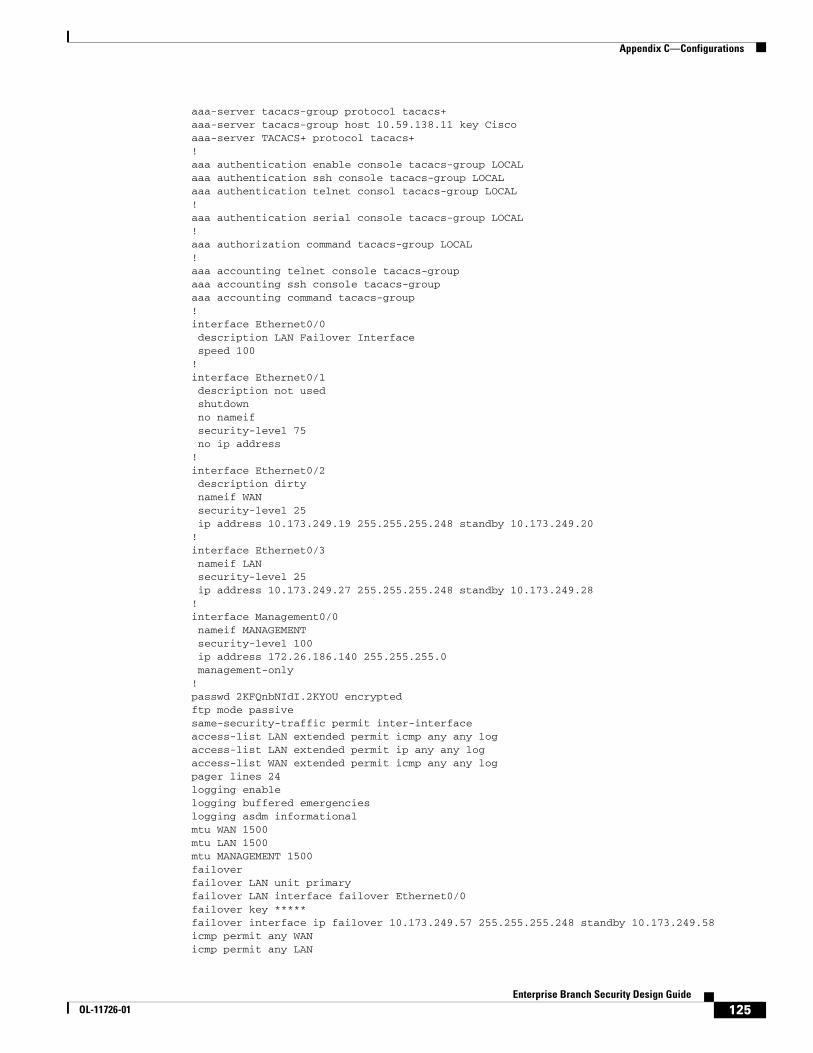
Appendix C—Configurations
aaa-server tacacs-group protocol tacacs+aaa-server tacacs-group host 10.59.138.11 key Ciscoaaa-server TACACS+ protocol tacacs+!aaa authentication enable console tacacs-group LOCALaaa authentication ssh console tacacs-group LOCALaaa authentication telnet consol tacacs-group LOCAL!aaa authentication serial console tacacs-group LOCAL!aaa authorization command tacacs-group LOCAL!aaa accounting telnet console tacacs-groupaaa accounting ssh console tacacs-groupaaa accounting command tacacs-group!interface Ethernet0/0 description LAN Failover Interface speed 100!interface Ethernet0/1 description not used shutdown no nameif security-level 75 no ip address!interface Ethernet0/2 description dirty nameif WAN security-level 25 ip address 10.173.249.19 255.255.255.248 standby 10.173.249.20!interface Ethernet0/3 nameif LAN security-level 25 ip address 10.173.249.27 255.255.255.248 standby 10.173.249.28!interface Management0/0 nameif MANAGEMENT security-level 100 ip address 172.26.186.140 255.255.255.0 management-only!passwd 2KFQnbNIdI.2KYOU encryptedftp mode passivesame-security-traffic permit inter-interfaceaccess-list LAN extended permit icmp any any logaccess-list LAN extended permit ip any any logaccess-list WAN extended permit icmp any any logpager lines 24logging enablelogging buffered emergencieslogging asdm informationalmtu WAN 1500mtu LAN 1500mtu MANAGEMENT 1500failoverfailover LAN unit primaryfailover LAN interface failover Ethernet0/0failover key *****failover interface ip failover 10.173.249.57 255.255.255.248 standby 10.173.249.58icmp permit any WANicmp permit any LAN
125Enterprise Branch Security Design Guide
OL-11726-01
Appendix C—Configurations
asdm image disk0:/asdm-504.binno asdm history enablearp timeout 14400access-group WAN in interface WANaccess-group LAN in interface LANroute WAN 10.173.249.8 255.255.255.248 10.173.249.18 1route WAN 10.173.249.0 255.255.255.248 10.173.249.17 1route WAN 10.173.255.2 255.255.255.255 10.173.249.18 1route WAN 10.173.255.1 255.255.255.255 10.173.249.17 1route WAN 0.0.0.0 0.0.0.0 10.173.249.22 1route LAN 10.173.192.0 255.255.192.0 10.173.249.29 1route LAN 10.100.0.0 255.255.0.0 10.173.249.29 1route LAN 10.100.0.0 255.255.0.0 10.173.249.30 1route LAN 10.173.192.0 255.255.192.0 10.173.249.30 1route MANAGEMENT 64.102.0.0 255.255.0.0 172.26.186.1 1timeout xlate 3:00:00timeout conn 1:00:00 half-closed 0:10:00 udp 0:02:00 icmp 0:00:02timeout sunrpc 0:10:00 h323 0:05:00 h225 1:00:00 mgcp 0:05:00timeout mgcp-pat 0:05:00 sip 0:30:00 sip_media 0:02:00timeout uauth 0:05:00 absolutehttp server enablehttp 192.168.1.0 255.255.255.0 MANAGEMENThttp 64.102.0.0 255.255.0.0 MANAGEMENTno snmp-server locationno snmp-server contactsnmp-server enable traps snmp authentication linkup linkdown coldstarttelnet 64.102.0.0 255.255.0.0 MANAGEMENTtelnet timeout 480ssh timeout 5console timeout 0Cryptochecksum:3b5322ce5aee825616f20254baacbdba: end
Access Router #1 Configuration
Current configuration : 5991 bytes!version 12.4no service padservice tcp-keepalives-inservice tcp-keepalives-outservice timestamps debug datetime msecservice timestamps log datetime msec localtimeservice password-encryption!hostname ksb-2821-1!boot-start-markerboot system flash flash:c2800nm-advipservicesk9-mz.124-6.2.Tboot-end-marker!logging countlogging buffered 8192 debugginglogging rate-limit 5no logging consoleenable password 7 045802150C2E!aaa new-model!!aaa authentication login ssh_users group tacacs+
126Enterprise Branch Security Design Guide
OL-11726-01

Appendix C—Configurations
aaa accounting send stop-record authentication failureaaa accounting exec ssh_users stop-only group tacacs+aaa accounting commands 15 ssh_users stop-only group tacacs+!aaa session-id common!resource policy!clock timezone est -5no ip source-route!ip nbar port-map custom-03 tcp 5554 9996ip nbar port-map custom-02 udp 1434ip nbar port-map custom-01 tcp 3200 3201 3202 3203 3600ip nbar port-map netbios udp 135 137 138 139 445ip nbar port-map netbios tcp 137 139 445ip cef!logging buffered 65535 debugginglogging rate-limit all 20enable secret 5 $1$./PL$wO4j2/f8KIS2Plt8NYPh0.!no ip domain lookup!!!no ip bootp serverno ip domain lookupip domain name ese.cisco.comip ssh time-out 60ip ssh authentication-retries 2ip ssh source-interface FastEthernet0/0ip ips deny-action ips-interfaceip ips signature 1107 0 disableip ips signature 2000 0 disableip ips signature 2001 0 disableip ips name KSBlogin block-for 30 attempts 3 within 200login delay 2!!track resolution ip route EIGRP 30000!track 15 rtr 15 delay up 90!track 20 rtr 15 delay up 95!track 30 ip route 192.168.2.0 255.255.255.0 metric threshold threshold metric up 50!track 50 ip route 0.0.0.0 0.0.0.0 metric threshold!username cisco password 7 14141B180F0B!class-map match-all BRANCH-BULK-DATA match access-group name BULK-DATA-APPSclass-map match-all SQL-SLAMMER match protocol custom-02 match packet length min 404 max 404class-map match-all BULK-DATA match ip dscp af11 af12class-map match-all INTERACTIVE-VIDEO
127Enterprise Branch Security Design Guide
OL-11726-01

Appendix C—Configurations
match ip dscp af41 af42class-map match-any CALL-SIGNALLING match ip dscp cs3 match ip dscp af31class-map match-any BRANCH-SCAVENGER match protocol napster match protocol gnutella match protocol fasttrack match protocol kazaa2class-map match-all NET-MGMG match ip dscp af21 af22class-map match-any BRANCH-TRANSACTIONAL-DATA match protocol citrix match protocol ldap match protocol sqlnet match protocol http url "*cisco.com" match protocol custom-01class-map match-all BRANCH-MISSION-CRITICAL match access-group name MISSION-CRITICAL-SERVERSclass-map match-any WORMS match protocol http url "*.ida*" match protocol http url "*cmd.exe*" match protocol http url "*root.exe*" match protocol http url "*readme.eml*" match class-map SQL-SLAMMER match protocol exchange match protocol netbios match protocol custom-03class-map match-all VOICE match ip dscp ef match ip precedence 5class-map match-all MISSION-CRITICAL-DATA match ip dscp 25class-map match-any BRANCH-NET-MGMT match protocol snmp match protocol syslog match protocol telnet match protocol nfs match protocol dns match protocol icmp match protocol tftpclass-map match-all ROUTING match ip dscp cs6class-map match-all SCAVENGER match ip dscp cs1!policy-map BRANCH-LAN-EDGE-OUT class CLASS-DEFAULT set cos dscppolicy-map BRANCH-LAN-EDGE-IN class BRANCH-MISSION-CRITICAL set ip dscp 25 class BRANCH-TRANSACTIONAL-DATA set ip dscp af21 class BRANCH-NET-MGMT set ip dscp cs2 class BRANCH-BULK-DATA set ip dscp af11 class BRANCH-SCAVENGER set ip dscp cs1 class WORMS drop class CLASS-DEFAULT set ip dscp default
128Enterprise Branch Security Design Guide
OL-11726-01

Appendix C—Configurations
!interface Loopback0 ip address 10.173.192.1 255.255.255.255!interface GigabitEthernet0/0 no ip address duplex auto speed auto!interface GigabitEthernet0/1 ip address 10.173.251.2 255.255.255.0 ip access-group NO_INITIATE in no ip redirects no ip unreachables no ip proxy-arp duplex auto speed auto ip ips KSB in service-policy input BRANCH-LAN-EDGE-IN service-policy output BRANCH-LAN-EDGE-OUT standby 10 ip 10.173.251.1 standby 10 priority 110 standby 10 preempt standby 10 track 15 decrement 20 standby 15 ip 10.173.251.254 standby 15 preempt!interface GigabitEthernet1/0 ip address 10.173.249.41 255.255.255.248 no ip redirects no ip unreachables no ip proxy-arp ip ips KSB in ip access-group SANITIZE_LAN in service-policy input BRANCH-LAN-EDGE-IN service-policy output BRANCH-LAN-EDGE-OUT!interface GigabitEthernet1/0.1 encapsulation dot1Q 206 ip address 10.173.249.25 255.255.255.248 no ip redirects no ip unreachables no ip proxy-arp no snmp trap link-status ip ips KSB in service-policy input BRANCH-LAN-EDGE-IN service-policy output BRANCH-LAN-EDGE-OUT standby 1 ip 10.173.249.30 standby 1 priority 110 standby 1 preempt standby 1 track 20 decrement 20 standby 2 ip 10.173.249.29 standby 2 preempt!!router eigrp 30 redistribute static metric 1500 100 255 1 1500 network 10.0.0.0 no auto-summary no eigrp log-neighbor-warnings!ip route 0.0.0.0 0.0.0.0 10.173.249.27 track 15ip route 10.59.136.10 255.255.255.255 10.173.249.27ip route 10.173.249.16 255.255.255.248 10.173.249.27
129Enterprise Branch Security Design Guide
OL-11726-01
Appendix C—Configurations
!!ip http serverno ip http secure-serverip tacacs source-interface Loopback0!ip access-list extended BULK-DATA-APPS permit tcp any any eq ftp permit tcp any any eq ftp-data permit tcp any any eq pop3 permit tcp any any eq 143!ip access-list extended MISSION-CRITICAL-SERVERS permit ip any 10.173.110.0 0.0.0.255 permit ip any 10.173.111.0 0.0.0.255ip access-list extended NO_INITIATE permit udp 10.173.251.0 0.0.0.255 host 10.57.170.2 eq syslog deny ip any any logip access-list extended SANITIZE_LAN deny ip 10.173.249.24 0.0.0.7 any deny ip 10.173.249.0 0.0.0.15 any permit ip 10.173.192.0 0.0.63.255 any!ip sla 15 icmp-echo 10.59.136.10 source-ip 10.173.249.25 tos 46!!!!!tacacs-server host 10.59.138.11tacacs-server directed-requesttacacs-server key 7 13061E010803557878!control-plane!!line con 0 flowcontrol hardwareline aux 0line vty 0 4 exec-timeout 120 0 password 7 1511021F0725 accounting commands 15 ssh_users accounting exec ssh_users login authentication ssh_users exec prompt timestamp transport input ssh transport output all!!scheduler allocate 20000 1000ntp clock-period 17180301ntp peer 10.173.249.17ntp peer 10.173.249.18!webvpn context Default_context ssl authenticate verify all ! no inservice!!webvpn context dummy
130Enterprise Branch Security Design Guide
OL-11726-01
Appendix C—Configurations
ssl authenticate verify all ! no inservice!!end
ksb-2821-1#
Access Router #2 Configuration
Current configuration : 5546 bytes!version 12.4no service padservice tcp-keepalives-inservice tcp-keepalives-outservice timestamps debug datetime msecservice timestamps log datetime msec localtimeservice password-encryption!!hostname ksb-2821-2!boot-start-markerboot system flash flash:c2800nm-advipservicesk9-mz.124-6.2.Tboot-end-marker!logging countlogging buffered 8192 debugginglogging rate-limit 5no logging consoleenable password 7 045802150C2E!aaa new-model!!aaa authentication login ssh_users group tacacs+aaa accounting send stop-record authentication failureaaa accounting exec ssh_users stop-only group tacacs+aaa accounting commands 15 ssh_users stop-only group tacacs+!aaa session-id common!resource policy!clock timezone est -5no ip source-route!ip nbar port-map custom-03 tcp 5554 9996ip nbar port-map custom-02 udp 1434ip nbar port-map custom-01 tcp 3200 3201 3202 3203 3600ip nbar port-map netbios udp 135 137 138 139 445ip nbar port-map netbios tcp 137 139 445ip cef!logging buffered 65535 debugginglogging rate-limit all 20enable secret 5 $1$./PL$wO4j2/f8KIS2Plt8NYPh0.!no ip domain lookup!
131Enterprise Branch Security Design Guide
OL-11726-01

Appendix C—Configurations
!!no ip bootp serverno ip domain lookupip domain name ese.cisco.comip ssh time-out 60ip ssh authentication-retries 2ip ssh source-interface FastEthernet0/0ip ips deny-action ips-interfaceip ips signature 1107 0 disableip ips signature 2000 0 disableip ips signature 2001 0 disableip ips name KSBlogin block-for 30 attempts 3 within 200login delay 2!!track 15 rtr 15 delay up 90!track 20 rtr 15 delay up 95!username cisco password 7 14141B180F0B!class-map match-all BRANCH-BULK-DATA match access-group name BULK-DATA-APPSclass-map match-all SQL-SLAMMER match protocol custom-02 match packet length min 404 max 404class-map match-all BULK-DATA match ip dscp af11 af12class-map match-all INTERACTIVE-VIDEO match ip dscp af41 af42class-map match-any CALL-SIGNALLING match ip dscp cs3 match ip dscp af31class-map match-any BRANCH-SCAVENGER match protocol napster match protocol gnutella match protocol fasttrack match protocol kazaa2class-map match-all NET-MGMG match ip dscp af21 af22class-map match-any BRANCH-TRANSACTIONAL-DATA match protocol citrix match protocol ldap match protocol sqlnet match protocol http url "*cisco.com" match protocol custom-01class-map match-all BRANCH-MISSION-CRITICAL match access-group name MISSION-CRITICAL-SERVERSclass-map match-any WORMS match protocol http url "*.ida*" match protocol http url "*cmd.exe*" match protocol http url "*root.exe*" match protocol http url "*readme.eml*" match class-map SQL-SLAMMER match protocol exchange match protocol netbios match protocol custom-03class-map match-all VOICE match ip dscp ef match ip precedence 5
132Enterprise Branch Security Design Guide
OL-11726-01

Appendix C—Configurations
class-map match-all MISSION-CRITICAL-DATA match ip dscp 25class-map match-any BRANCH-NET-MGMT match protocol snmp match protocol syslog match protocol telnet match protocol nfs match protocol dns match protocol icmp match protocol tftpclass-map match-all ROUTING match ip dscp cs6class-map match-all SCAVENGER match ip dscp cs1!policy-map BRANCH-LAN-EDGE-OUT class CLASS-DEFAULT set cos dscppolicy-map BRANCH-LAN-EDGE-IN class BRANCH-MISSION-CRITICAL set ip dscp 25 class BRANCH-TRANSACTIONAL-DATA set ip dscp af21 class BRANCH-NET-MGMT set ip dscp cs2 class BRANCH-BULK-DATA set ip dscp af11 class BRANCH-SCAVENGER set ip dscp cs1 class WORMS drop class CLASS-DEFAULT set ip dscp default!!!interface Loopback0 ip address 10.173.192.2 255.255.255.255!interface GigabitEthernet0/0 no ip address duplex auto speed auto!!interface GigabitEthernet0/1 ip address 10.173.251.3 255.255.255.0 ip access-group NO_INITIATE in no ip redirects no ip unreachables no ip proxy-arp duplex auto speed auto ip ips KSB in service-policy input BRANCH-LAN-EDGE-IN service-policy output BRANCH-LAN-EDGE-OUT standby 10 ip 10.173.251.1 standby 10 preempt standby 15 ip 10.173.251.254 standby 15 priority 110 standby 15 preempt standby 15 track 15 decrement 20!interface GigabitEthernet1/0
133Enterprise Branch Security Design Guide
OL-11726-01
Appendix C—Configurations
ip address 10.173.249.33 255.255.255.248 no ip redirects no ip unreachables no ip proxy-arp ip ips KSB in ip access-group SANITIZE_LAN in service-policy input BRANCH-LAN-EDGE-IN service-policy output BRANCH-LAN-EDGE-OUT !!interface GigabitEthernet1/0.2 encapsulation dot1Q 206 ip address 10.173.249.26 255.255.255.248 no snmp trap link-status no ip redirects no ip unreachables no ip proxy-arp ip ips KSB in ip access-group SANITIZE_LAN in service-policy input BRANCH-LAN-EDGE-IN service-policy output BRANCH-LAN-EDGE-OUT standby 1 ip 10.173.249.30 standby 1 preempt standby 2 ip 10.173.249.29 standby 2 priority 110 standby 2 preempt standby 2 track 20 decrement 20!router eigrp 30 redistribute static metric 1500 100 255 1 1500 network 10.0.0.0 auto-summary no eigrp log-neighbor-warnings!ip route 0.0.0.0 0.0.0.0 10.173.249.27 track 15ip route 10.173.255.2 255.255.255.255 10.173.249.27!ip http serverno ip http secure-server!ip access-list extended BULK-DATA-APPS permit tcp any any eq ftp permit tcp any any eq ftp-data permit tcp any any eq pop3 permit tcp any any eq 143!ip access-list extended MISSION-CRITICAL-SERVERS permit ip any 10.173.110.0 0.0.0.255 permit ip any 10.173.111.0 0.0.0.255ip access-list extended NO_INITIATE permit udp 10.173.251.0 0.0.0.255 host 10.57.170.2 eq syslog deny ip any any logip access-list extended SANITIZE_LAN deny ip 10.173.251.24 0.0.0.7 any deny ip 10.173.249.0 0.0.0.15 any permit ip 10.173.192.0 0.0.63.255 any!ip sla 15 icmp-echo 10.173.255.2 timeout 350 frequency 5ip sla schedule 15 life forever start-time now!!
134Enterprise Branch Security Design Guide
OL-11726-01
Appendix C—Configurations
!!!tacacs-server host 10.59.138.11tacacs-server directed-requesttacacs-server key 7 13061E010803557878!control-plane!!line con 0line aux 0line vty 0 4 exec-timeout 120 0 password 7 1511021F0725 accounting commands 15 ssh_users accounting exec ssh_users login authentication ssh_users exec prompt timestamp transport input ssh transport output all !scheduler allocate 20000 1000ntp clock-period 17180203ntp peer 10.173.249.17ntp peer 10.173.249.18!webvpn context Default_context ssl authenticate verify all ! no inservice!!webvpn context dummy ssl authenticate verify all ! no inservice!!end
Stackwise Switch Master Configuration
Current configuration : 6556 bytes!version 12.2no service padservice timestamps debug uptimeservice timestamps log uptimeservice password-encryption!hostname ksb-3750-3!enable secret 5 $1$mybp$FDABFDda/4z9dXAaXPPUW.!no aaa new-modelswitch 1 provision ws-c3750g-24psip subnet-zero!ip dhcp pool data_lan network 10.173.195.0 255.255.255.0
135Enterprise Branch Security Design Guide
OL-11726-01

Appendix C—Configurations
default-router 10.173.195.1!!mls qos map policed-dscp 0 24 to 8mls qos map cos-dscp 0 8 16 24 32 46 48 56mls qos srr-queue output cos-map queue 1 threshold 3 5mls qos srr-queue output cos-map queue 2 threshold 1 2 4mls qos srr-queue output cos-map queue 2 threshold 2 3mls qos srr-queue output cos-map queue 2 threshold 3 6 7mls qos srr-queue output cos-map queue 3 threshold 3 0mls qos srr-queue output cos-map queue 4 threshold 3 1mls qos srr-queue output dscp-map queue 1 threshold 3 46mls qos srr-queue output dscp-map queue 2 threshold 1 16 18 20 22 25 32 34 36mls qos srr-queue output dscp-map queue 2 threshold 1 38mls qos srr-queue output dscp-map queue 2 threshold 2 24 26mls qos srr-queue output dscp-map queue 2 threshold 3 48 56mls qos srr-queue output dscp-map queue 3 threshold 3 0mls qos srr-queue output dscp-map queue 4 threshold 1 8mls qos srr-queue output dscp-map queue 4 threshold 3 10 12 14mls qos queue-set output 1 threshold 2 70 80 100 100mls qos queue-set output 1 threshold 4 40 100 100 100!!no file verify autospanning-tree mode pvstspanning-tree extend system-id!vlan internal allocation policy ascending!class-map match-all VVLAN-CALL-SIGNALING match access-group name VVLAN-CALL-SIGNALINGclass-map match-all VVLAN-VOICE match access-group name VVLAN-VOICEclass-map match-all VVLAN-ANY match access-group name VVLAN-ANY!!policy-map IPPHONE+PC-BASIC class VVLAN-VOICE set dscp ef police 128000 8000 exceed-action drop class VVLAN-CALL-SIGNALING set dscp cs3 police 32000 8000 exceed-action policed-dscp-transmit class VVLAN-ANY set dscp default police 32000 8000 exceed-action policed-dscp-transmit class class-default set dscp default police 5000000 8000 exceed-action policed-dscp-transmit!!interface GigabitEthernet1/0/1 srr-queue bandwidth share 1 70 25 5 srr-queue bandwidth shape 3 0 0 0 priority-queue out!interface GigabitEthernet1/0/2 srr-queue bandwidth share 1 70 25 5 srr-queue bandwidth shape 3 0 0 0 priority-queue out!interface GigabitEthernet1/0/3 srr-queue bandwidth share 1 70 25 5
136Enterprise Branch Security Design Guide
OL-11726-01
Appendix C—Configurations
srr-queue bandwidth shape 3 0 0 0 priority-queue out!interface GigabitEthernet1/0/4 srr-queue bandwidth share 1 70 25 5 srr-queue bandwidth shape 3 0 0 0 priority-queue out!interface GigabitEthernet1/0/5 srr-queue bandwidth share 1 70 25 5 srr-queue bandwidth shape 3 0 0 0 priority-queue out!interface GigabitEthernet1/0/6 srr-queue bandwidth share 1 70 25 5 srr-queue bandwidth shape 3 0 0 0 priority-queue out!interface GigabitEthernet1/0/7 srr-queue bandwidth share 1 70 25 5 srr-queue bandwidth shape 3 0 0 0 priority-queue out!interface GigabitEthernet1/0/8 srr-queue bandwidth share 1 70 25 5 srr-queue bandwidth shape 3 0 0 0 priority-queue out!interface GigabitEthernet1/0/9 srr-queue bandwidth share 1 70 25 5 srr-queue bandwidth shape 3 0 0 0 priority-queue out!interface GigabitEthernet1/0/10 srr-queue bandwidth share 1 70 25 5 srr-queue bandwidth shape 3 0 0 0 priority-queue out!interface GigabitEthernet1/0/11 srr-queue bandwidth share 1 70 25 5 srr-queue bandwidth shape 3 0 0 0 priority-queue out!interface GigabitEthernet1/0/12 srr-queue bandwidth share 1 70 25 5 srr-queue bandwidth shape 3 0 0 0 priority-queue out!interface GigabitEthernet1/0/13 srr-queue bandwidth share 1 70 25 5 srr-queue bandwidth shape 3 0 0 0 priority-queue out!interface GigabitEthernet1/0/14 srr-queue bandwidth share 1 70 25 5 srr-queue bandwidth shape 3 0 0 0 priority-queue out!interface GigabitEthernet1/0/15 srr-queue bandwidth share 1 70 25 5 srr-queue bandwidth shape 3 0 0 0 priority-queue out!interface GigabitEthernet1/0/16
137Enterprise Branch Security Design Guide
OL-11726-01

Appendix C—Configurations
srr-queue bandwidth share 1 70 25 5 srr-queue bandwidth shape 3 0 0 0 priority-queue out!interface GigabitEthernet1/0/17 srr-queue bandwidth share 1 70 25 5 srr-queue bandwidth shape 3 0 0 0 priority-queue out!interface GigabitEthernet1/0/18 srr-queue bandwidth share 1 70 25 5 srr-queue bandwidth shape 3 0 0 0 priority-queue out!interface GigabitEthernet1/0/19 srr-queue bandwidth share 1 70 25 5 srr-queue bandwidth shape 3 0 0 0 priority-queue out!interface GigabitEthernet1/0/20 srr-queue bandwidth share 1 70 25 5 srr-queue bandwidth shape 3 0 0 0 priority-queue out!interface GigabitEthernet1/0/21 srr-queue bandwidth share 1 70 25 5 srr-queue bandwidth shape 3 0 0 0 priority-queue out!interface GigabitEthernet1/0/22 switchport access vlan 186 srr-queue bandwidth share 1 70 25 5 srr-queue bandwidth shape 3 0 0 0 priority-queue out!interface GigabitEthernet1/0/23 switchport trunk encapsulation dot1q switchport mode trunk srr-queue bandwidth share 1 70 25 5 srr-queue bandwidth shape 3 0 0 0 priority-queue out!interface GigabitEthernet1/0/24 switchport access vlan 186 srr-queue bandwidth share 1 70 25 5 srr-queue bandwidth shape 3 0 0 0 priority-queue out!interface GigabitEthernet1/0/25 srr-queue bandwidth share 1 70 25 5 srr-queue bandwidth shape 3 0 0 0 priority-queue out!interface GigabitEthernet1/0/26 srr-queue bandwidth share 1 70 25 5 srr-queue bandwidth shape 3 0 0 0 priority-queue out!interface GigabitEthernet1/0/27 srr-queue bandwidth share 1 70 25 5 srr-queue bandwidth shape 3 0 0 0 priority-queue out!interface GigabitEthernet1/0/28
138Enterprise Branch Security Design Guide
OL-11726-01
Appendix D—References and Recommended Reading
srr-queue bandwidth share 1 70 25 5 srr-queue bandwidth shape 3 0 0 0 priority-queue out!interface Vlan1 no ip address shutdown!interface Vlan100 description data lan ip address 10.173.195.2 255.255.255.0 standby 100 ip 10.173.195.1!!ip classlessip http server!ip access-list extended VVLAN-ANY permit ip 10.1.110.0 0.0.0.255 anyip access-list extended VVLAN-CALL-SIGNALING permit tcp 10.1.110.0 0.0.0.255 any range 2000 2002ip access-list extended VVLAN-VOICE permit udp 10.1.110.0 0.0.0.255 any range 16384 32767!!control-plane!!line con 0line vty 0 4 password cisco no loginline vty 5 15 no login!!end
Appendix D—References and Recommended ReadingThis section provides the following references and additional information related to the subjects covered in this design guide:
• Documents:
– IPsec VPN WAN Design Overview—EDCS-467507
– IPsec Direct Encapsulation Design Guide—EDCS-467508
– p2p GRE over IPsec Design Guide—EDCS-467509
– Dynamic Multipoint VPN (DMVPN) Design Guide—EDCS-420853
– Virtual Tunnel Interface (VTI) Design Guide—EDCS-466645
– LAN Baseline Architecture Overview Branch Office Network— EDCS-488184
– LAN Baseline Architecture Branch Office Network Reference Design Guide—EDCS-488185
• Request For Comment (RFC) papers
– RFC-2547- BGP/MPLS VPNs
• Websites
139Enterprise Branch Security Design Guide
OL-11726-01
Appendix E—Acronyms
– Enterprise Systems Engineering (ESE)— http://wwwin.cisco.com/ios/systems/ese/
– ESE Enterprise Branch—http://wwwin.cisco.com/marketing/systems/ese/places/branch/
– Cisco Stackwise Technology White Paper— http://www.cisco.com/en/US/partner/products/hw/switches/ps5023/products_white_paper09186a00801b096a.shtml.
– Enterprise QoS Solution Reference Network Design Guide Version 3.3— http://www.cisco.com/application/pdf/en/us/guest/netsol/ns432/c649/ccmigration_09186a008049b062.pdf
– Cisco IOS Firewall Feature Set— http://www.cisco.com/en/US/partner/products/sw/securesw/ps1018/index.html
– Cisco ASA 5500 Series Adaptive Security Appliances— http://www.cisco.com/en/US/partner/products/ps6120/index.html
– Cisco IOS IPS Feature Set— http://www.cisco.com/en/US/partner/products/ps6634/products_ios_protocol_group_home.html
– Cisco IPv6 Reference Page— http://www.cisco.com/en/US/products/ps6553/products_ios_technology_home.html
– Cisco IP Routing Reference Page— http://www.cisco.com/en/US/products/ps6599/products_ios_protocol_group_home.html
– QoS Reference Page—http://www.cisco.com/go/qos
– AAA, TACACS+ and RADIUS Overview— http://www.cisco.com/en/US/products/sw/iosswrel/ps1835/products_configuration_guide_chapter09186a00800ca7a7.html
– Infrastructure Protection Overview— http://www.cisco.com/application/pdf/en/us/guest/products/ps1838/c1244/cdccont_0900aecd804ac831.pdf
– Cisco IOS IPS Supported Signature List— http://www.cisco.com/en/US/partner/products/ps6634/products_white_paper0900aecd8039e2e4.shtm
– LAN Baseline Architecture Overview—Branch Office Network— http://www.cisco.com/univercd/cc/td/doc/solution/lanovext.pdf
– LAN Baseline Architecture Branch Office Network Reference Design Guide— http://www.cisco.com/univercd/cc/td/doc/solution/lanovext.pdf
Appendix E—Acronyms
Term Definition
ATM Asynchronous Transfer Mode
DHCP Dynamic Host Configuration Protocol
DMVPN Dynamic Multipoint Virtual Private Network
DSL Digital Subscriber Line
140Enterprise Branch Security Design Guide
OL-11726-01
Appendix E—Acronyms
EIGRP Enhanced Interior Gateway Routing Protocol
FR Frame Relay
FTP File Transfer Protocol
GRE Generic Route Encapsulation
HSRP Hot Standby Router Protocol
IOS Internetwork Operating System
IPsec IP Security
ISP Internet Service Provider
MPLS Multi-Protocol Label Switching
OSPF Open Shortest Path First
p2p GRE Point-to-Point GRE
PVC Permanent Virtual Circuit
QoS Quality of Service
RADIUS Remote Authentication Dial In User System
VoIP Voice over IP
V3PN Voice and Video Enabled IPsec VPN
VPN Virtual Private Network
VTI Virtual Tunnel Interface
WAN Wide Area Network
141Enterprise Branch Security Design Guide
OL-11726-01

Appendix E—Acronyms
142Enterprise Branch Security Design Guide
OL-11726-01