Embed Size (px)
Citation preview

Entegrity Smart™ Lock
Installation Instructions

Parts List:Latch (either 2 3/4” or 2 3/8”)Adjustment ToolLock MotorOutside ShankMounting PlateInside ShankBattery PackInside CoverInside HandleOutside Cover
Outside HandleSFIC CoreOperating Keys (2)Control Key (1)#8x3/4” screws (2)M6x10 screws (2)M5x38mm screws (4)M4x12 hex screw (1)M3x10 pan head screw (1)
The Entegrity Smart Lock can only be installed on a door that:4 is between 1 3/8” and 2” thick.4 has a 2 1/8” door prep.4 has 2 3/4” or 2 3/8” backset.
1. Checklist:a. Four (4) AA lithium batteries - not included.b. #2 Philips head screwdriver.c. 5/16” Drill bit – only required for ANSI Grade 1 installation.

2. FOR ANSI Grade 1 Installation ONLY:
a. Determine which backset fits your installation (2 3/4” or 2 3/8”).b. Fold installation template along the dashed line, place it on the door and mark the holes.c. Drill the two 5/16” holes for the ANSI Grade 1 posts.
IF ANSI GRADE 1 IS NOT REQUIRED REMOVE THE OUTER STUDS AND SKIP TO SECTION 3
3. Latch Installation
Ensure the latch bolt bevel is facing the closing direction of the door and secure the Latch to the door using two (2) #8x3/4” screws.
The Latch should extend into the hole as shown. If it extends too far, you have the incorrect Latch.

4. Adjust for Door Thickness
5. Outside Shank
Align and connect the Lock Motor to the Outside Shank.
Insert the Adjustment Tool and rotate the plate to the appropriate door thickness mark.
Latch Retractor
Insert the Lock Motor so that the latch retractor faces the edge of the door.

The large notch on the Outside Shank should face away from the edge of the door.
The latch retractor should catch the Latch and the Lock Motor cable should face away from the edge of the door.
6. Mounting Plate
Carefully feed the Lock Motor cable through the hole and attach the Mounting Plate using two (2) M5x38mm screws.
Large Notch

7. Inside Shank
Carefully feed the Lock Motor cable through the hole on the Inside Shank.
8. Battery Installation
Install four (4) AA lithium batteries in the Battery Pack.
Align the Inside Shank so the large notch faces away from the edge of the door. Attach the Inside Shank to the Mounting Plate using two (2) M6x10mm screws.
For ANSI Grade 1 Installations only, attach the Mounting Plate to the outer studs using the two (2) additional M5X38mm screws.
Large Notch

Insert the Battery Pack in the Inside Cover using one (1) flathead M4x12 hex screw. After the screw is fully tightened, loosen the screw by one full turn.
9. PC Board
Plug the Lock Motor cable into the Inside Cover PC board.
10. Inside Cover
Place the Inside Cover on the Mounting Plate and fully tighten the battery pack screw loosened in step 8. Use one (1) M3x10 pan head screw to secure the Inside Cover to the Mounting Plate.
Make sure the wires do not get pinched when attaching the cover.

11. Inside Handle
Slide the Inside Handle over the Inside Shank until it clicks.
12. Outside Cover
Make sure that the notch is at the bottom with the two indents on the left and right and snap the Outside Cover over the Outside Shank.
13. SFIC Core
Insert the SFIC Core into the Outside Handle using the Control Key and remove the Control Key.
Notch
Indent
14. Outside Handle
Ensure the two pins in the Outside Shank (1A) align with the two holes in SFIC Core (1B). With the Operating Key inserted n the Outside Handle, slide it over the Outside Shank until it clicks in place and can’t be removed (1C).
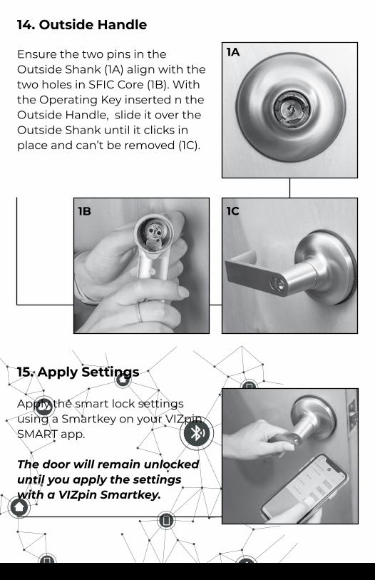
15. Apply Settings
Apply the smart lock settings using a Smartkey on your VIZpin SMART app.
The door will remain unlocked until you apply the settings with a VIZpin Smartkey.
1A
1B 1C

(717) 327-4244VIZpin.com
355 E. Liberty Street, Suite 210Lancaster, PA 17602